EP2839714B1 - Method and radio network node for managing radio resources - Google Patents
Method and radio network node for managing radio resourcesDownload PDFInfo
- Publication number
- EP2839714B1 EP2839714B1EP12723950.7AEP12723950AEP2839714B1EP 2839714 B1EP2839714 B1EP 2839714B1EP 12723950 AEP12723950 AEP 12723950AEP 2839714 B1EP2839714 B1EP 2839714B1
- Authority
- EP
- European Patent Office
- Prior art keywords
- time
- requests
- threshold
- point
- radio resources
- Prior art date
- Legal status (The legal status is an assumption and is not a legal conclusion. Google has not performed a legal analysis and makes no representation as to the accuracy of the status listed.)
- Active
Links
Images


Classifications
- H—ELECTRICITY
- H04—ELECTRIC COMMUNICATION TECHNIQUE
- H04W—WIRELESS COMMUNICATION NETWORKS
- H04W28/00—Network traffic management; Network resource management
- H04W28/02—Traffic management, e.g. flow control or congestion control
- H04W28/0215—Traffic management, e.g. flow control or congestion control based on user or device properties, e.g. MTC-capable devices
- H—ELECTRICITY
- H04—ELECTRIC COMMUNICATION TECHNIQUE
- H04W—WIRELESS COMMUNICATION NETWORKS
- H04W76/00—Connection management
- H04W76/30—Connection release
- H04W76/38—Connection release triggered by timers
- H—ELECTRICITY
- H04—ELECTRIC COMMUNICATION TECHNIQUE
- H04W—WIRELESS COMMUNICATION NETWORKS
- H04W72/00—Local resource management
- H04W72/50—Allocation or scheduling criteria for wireless resources
- H04W72/51—Allocation or scheduling criteria for wireless resources based on terminal or device properties
- H—ELECTRICITY
- H04—ELECTRIC COMMUNICATION TECHNIQUE
- H04W—WIRELESS COMMUNICATION NETWORKS
- H04W72/00—Local resource management
- H04W72/50—Allocation or scheduling criteria for wireless resources
- H04W72/56—Allocation or scheduling criteria for wireless resources based on priority criteria
Definitions
- Embodiments hereinrelate to a method and a radio network node in a cellular radio communication system.
- a radio network node and a method therein for managing radio resourcesare disclosed.
- a so called prioritization functionresolves conflicts in situations where resources in the systems are limited.
- the conflictsrelate to which task or connection should be allowed to use the resources.
- a known method for prioritizationis based on pre-emption.
- a pre-emption based prioritization method for a computer systeman ongoing task will be interrupted for the benefit of a further task with higher priority than the ongoing task.
- the ongoing taskis interrupted, its resources are released and thus returned to the system before the ongoing task has been completed, i.e. the ongoing task is pre-emptied. Then the returned resources may be used by the further task. It is intended that the interrupted task, which previously was the ongoing task, will be resumed when the further task with higher priority has been completed.
- Queuing schemesplace tasks in a queue, in which the tasks remain while waiting for resources to be available.
- a resourceis released when the further task is finalized.
- prioritizationis performed at many levels. For example, prioritization for a connection associated with a user equipment is managed at a level where admission control occurs.
- the admission control for the connectionis performed by a radio base station of the cellular radio communication system at initial access and at handover of the user equipment.
- a requestis sent from the user equipment to the radio base station which then controls admission of the request.
- a connection of the user equipmentmay be moved from a first base station to a second base station.
- an aspect of mobilityapplies to connections, but not to tasks.
- the second base stationpriorities resources to be used for handling user equipments performing handover to the second base station.
- user equipments performing handoverare prioritized, it may happen that a user equipment performing initial access to the second base station is not allowed to access the second base station. In this manner, mobility of user equipments is provided as seamlessly as possible.
- a key aspectis how inactive User Equipments (UE) are managed in the base station.
- UEUser Equipments
- the protocol state modeldefines two states of a user equipment in relation to a base station; connected state and idle state. Radio resources are allocated to user equipments in connected state. The radio resources are released when the user equipment is transitioned to idle state. The transition from connected state to idle state is usually performed when the user equipment has been inactive for a specific time period, which will be referred to as an idle state time period herein. When the idle state time period has passed, it is no longer plausible to assume that the user equipment will send or receive any user data in a near future.
- a reservoir of radio resourcesare reserved.
- the reservoir of radio resourcesare reserved for the benefit of admitting a request for radio resources in conjunction with handover (handover request) to the base station.
- handover requesta request for radio resources in conjunction with handover
- any request for radio resources in conjunction with initial accessinitial access request
- the number of connections typically held by the base stationis reduced, since the reservoir will always reserve some radio resource for handover requests.
- all reserved radio resourcesmay be allocated to connections established in response to handover requests.
- ARPAllocation and Retention Priority
- Document EP 1 619 906 A1shows a method for adaptive setting PPP inactivity timers in a wireless packet data network based on the current load situation being represented by the number allocated IP addresses.
- Document WO 03/069934 A1shows an access point including active-to-standby transition timers with dynamically set values for controlling mobile stations for transitioning from active to standby mode.
- the timer valuevaries based on a particular required QoS.
- An object of embodiments of the inventionis to improve management of radio resources in a cellular radio communication system.
- the objectis achieved by a method for managing radio resources according 10 claim 1.
- the objectis achieved by a radio network node configured to manage radio resources according to claim 10.
- radio resourceswhich are allocated to user equipments that are considered to be inactive, will be released upon reception of a request for radio resources.
- Another advantageis that blocking of initial access requests is reduced thanks to that the need for a reservoir of radio resources reserved for handover requests is alleviated.
- Figure 1shows a cellular radio communication system 100, such as an LTE system, or any other cellular network technology supporting handover from one cell to another.
- a cellular radio communication system 100such as an LTE system, or any other cellular network technology supporting handover from one cell to another.
- the cellular radio communication system 100comprises a radio network node 130.
- the radio network node 130may be an evolved NodeB (eNB), a radio base station, a radio network controller or a radio base station controller.
- eNBevolved NodeB
- the radio network node 130may be an evolved NodeB (eNB), a radio base station, a radio network controller or a radio base station controller.
- a first and a second user equipment 110, 120may be located in the vicinity of the radio network node 130.
- the first user equipment 110is connected to the radio network node 130. This means that the radio network node 130 has allocated radio resources for holding a first connection C1 towards the first user equipment 110.
- a second connection C2may be established.
- connectionmay refer to a Radio Bearer, such as a Signalling Radio Bearer (SRB) 1, as described in TS 36.331 or the like.
- SRBSignalling Radio Bearer
- the term "user equipment”may refer to a mobile phone, a cellular phone, a Personal Digital Assistant (PDA) equipped with radio communication capabilities, a smartphone, a tablet computer, a laptop equipped with an internal or external mobile broadband modem, a portable electronic radio communication device or the like.
- PDAPersonal Digital Assistant
- the concept of user equipmentalso comprises devices with communication capability of machine-type character such as sensors, measurement devices etc that not necessarily is in any interaction with a user.
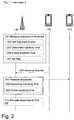
- FIG 2a schematic combined signalling and flowchart of an exemplifying method in the radio communication system of Figure 1 is illustrated.
- the radio network node 130performs a method for releasing a set of radio resources.
- the release of the set of radio resourcesare performed in conjunction with admitting the second user equipment 120 into the radio network node 130.
- the set of radio resourcesare allocated to a first user equipment 110.
- the radio network node 130does not have any available radio resources, i.e. all radio resources handled by the radio network node 130 are allocated to connections for user equipments connected to the radio network node 130.
- a connected user equipmentmay refer to a user equipment in RRC_CONNECTED_MODE as known from Third Generation Partnership Project (3GPP).
- the radio network node 130In order to determine if the first user equipment 110 is inactive, the radio network node 130 measures an inactivity time period of the first user equipment 110. In action 207 below, the inactivity time period will be used.
- the inactivity time periodmay indicate a difference between a first point in time and a second point in time.
- the inactivity time periodis referred to as inactivity time.
- the first point in timemay indicate time at most recent transmission of user data for the first user equipment 110.
- the most recent transmissionis the last transmission, comprising user data, transmitted by the first user equipment 110.
- Transmissions relating to control signalling, such as channel quality reports or the like,are not taken into account when measuring the inactivity time period. Thus, a channel quality report does not set the first point in time.
- the second point in timemay then indicate time at reception of the request from the second user equipment 120.
- the second point in timemay be at periodic or irregular intervals from the first point in time.
- the first point in time and the second point in timemay be established.
- the radio network node 130may thus set the first point in time, which is indicates time at most recent transmission of user data for the first user equipment 110.
- the radio network node 130stores the first point in time in a memory 540 shown in Figure 5 below.
- the radio network node 130may determine the inactivity time period as a difference between the first point in time and the second point in time.
- the radio network node 130may check whether the inactivity time period exceeds the threshold.
- the radio network node 130may set a flag to indicate that the set of radio resources are eligible for release. This action is performed when the inactivity time period exceeds the threshold.
- the flagwhen the flag is set to one, it shall mean that if a request for radio resources is received, then the radio network node 130 may release the set of radio resources. In case, there are multiple sets of radio resources, there will be multiple flags, where each flag is associated to a respective set of radio resources.
- the radio network node 130When actions 203, 204 and 205 are performed, the radio network node 130 prepares for a reception of a request for radio resources, as in action 206. Thus, when an actual request for radio resources is received, the radio network node 130 may advantageously merely check the flag and proceed accordingly. As a consequence, processing time of the request for radio resources may be reduced as compared to when determination of the inactivity time period and the checking, as in action 208 and 209 below, are performed upon reception of a request.
- the flagwould have to be reset such as to indicate that the set of radio resource allocated to the first user equipment 110 are not eligible for release.
- the radio network node 130receives a request for radio resources from the second user equipment 120. In this manner, the second user equipment 120 seeks to be admitted into the radio network node 130. For example, the radio network node 130 may seek to be admitted at initial access or at handover.
- the requestmay indicate that the second user equipment 120 needs radio resources in order for a connection to be established.
- the connectionmay enable communication between the radio network node 130 and the second user equipment 120.
- the requestmay be an admission request, such as an RRCConnectionRequest message.
- the RRCConnectionRequest messageis specified in TS 36.331.
- the radio network node 130releases the set of radio resources when the inactivity time period exceeds a threshold.
- the inactivity time periodexceeds the threshold when the inactivity time period is greater than or equal to the threshold.
- the thresholdindicates that the set of radio resources are releasable due to inactivity of the first user equipment 110.
- the threshold and categories of the requestare considered.
- the releasing of the set of radio resourcesis triggered by the request.
- the radio network node 130may send a message to the first user equipment 110.
- the messagemay inform the first user equipment 110 about the release of the set of radio resources.
- One example in LTE of such a messageis RRC connection release.
- the radio network node 130may determine the inactivity time period as a difference between the first point in time and the second point in time.
- the radio network node 130may check whether the inactivity time period exceeds the threshold.
- the radio network node 130When actions 208 and 209 are performed, the radio network node 130 only determines the inactivity time period and compares, or checks, with the threshold when a request has been received. Thus, the radio network node 130 only spends processing resources for this purpose when required.
- the radio network node 130may allocate at least some of the radio resources of the set to the second user equipment 120. In this manner, the request is granted and the second user equipment is admitted into the radio network node 130.
- FIG 3a schematic overview of an exemplifying scenario is shown.
- a third user equipment 140in addition to the first and second user equipments 110, 120 of Figure 1 , is illustrated.
- Inactivity time periods A1, A2, A3, A4 from last transmission of user dataare illustrated for the first user equipment 110 and the third user equipment 140. Since the inactivity time period A2 is greater than or equal to the threshold T at time of the request, shown by the dashed line, radio resources allocated to the first user equipment 110 will be released.
- the inactivity time period A4 of the third user equipment 140is less than the threshold T. Therefore, the radio resources allocated to the third user equipment 140 are not released.
- the radio network node 130checks whether the inactivity time period is greater than or equal to the threshold when the request for radio resources has been received. In this manner, comparison between the inactivity time period and the threshold are only performed when there is a need for release of radio resources.
- the radio network node 130compares a current inactivity time period A3 to the threshold T without first being triggered by a request. This kind of comparisons may be made at periodic intervals or irregularly such as when the radio network node 130 has overcapacity in terms of processing power.
- the radio network node 130sets an indicator F, such as a flag or the like.
- the indicator Fis set to indicate that radio resources are eligible for release in view of incoming requests for radio resources when the threshold T is less than the current inactivity time period A3.
- Inactivity time period A1is not long enough compared to the threshold T.
- the indicator Fis not set to indicate that resources are eligible for release.
- a respective threshold for each category that is to be treated differently than other requestsis required.
- requests within the same categorymay be treated as different categories when the requests are associated with different levels within the same category.
- the different levelsrefer here to any levels that are applicable within the category.
- the levelsmay be degrees of resource utilization in case the category refers to resource utilization as explained below.
- the requestis associated with a first category of requests or a second category of requests.
- the requestmay be associated with handover requests or initial access requests.
- the first category of requests and the second category of requestsmay relate to one or more of:
- Initial accessrelates to when the second user equipment 120 is initially accessing, e.g. at power up of the second user equipment 120, the radio network node 130 in order to request radio resources.
- Handoverrelates to when the second user equipment 120 is handed over to the radio network node 130 from a further network node (not shown).
- Priority of an E-RABis signified by its ARP settings and expresses how aggressively, the radio network node 130 may pre-empt resources already assigned at the time of the request.
- Establishment causemay be set to the value "emergency" (see TS 36.331). Requests that are set to "emergency” may for instance be prioritized compared to any other value(s) of establishment cause. As described herein, prioritization among requests may be based on differentiation of the inactivity time period.
- the resource utilizationmay be represented by Quality of service Class Indicator (QCI). Hence, the resource utilization relates to expected radio resource utilization if, or when, a request of the first degree of resource utilization would be granted. Resource utilization may also be represented by Guaranteed Bit Rate (GBR) values, which in LTE is indicated by the GBR QoS Information (see TS 36.413).
- QCIQuality of service Class Indicator
- GBRGuaranteed Bit Rate
- the indicator Fthere a plurality of indicators, one for each category or levels within a category, would be required to handle prioritization between categories or levels of within a category.
- FIG. 4an exemplifying timeline is shown in order to illustrate prioritization among requests of different categories.
- a plurality of thresholds T0, T1, T2, T3are indicated.
- Each of the thresholdsindicates that the set of radio resources are releasable due to inactivity of the first user equipment 110.
- a respective threshold for each categorymay enable prioritization.
- the thresholdmay comprise a first threshold associated with the first category of requests and a second threshold associated with the second category of requests.
- the first threshold T1relates to handover requests and the second threshold T2 relates to initial access requests. Then, handover requests will be prioritized over initial access requests when the first threshold is less than the second threshold.
- the first degree of resource utilizationmay be represented by a first QCI and the second degree of resource utilization may be represented by a second QCI.
- the first QCImay represent a first service that is known to require the first degree of resource utilization and the second QCI may represent a second service that is known to require a second degree of resource utilization.
- the first degree of resource utilizationsis assumed to be less than the second degree of resource utilization. Now, if the first QCI and the second QCI is associated with the first and second threshold, respectively, admission requests of the first degree of resource utilization will be prioritized over admission requests of the second degree of resource utilization when the first threshold is lower than the second threshold. In a scenario, in which available radio resources are limited or even non-existent, this may be beneficial.
- the first degree of resource utilizationmay be represented by a first GBR requested by a first user equipment and the second degree of resource utilization may be represented by a second GBR requested by a second user equipment.
- the first GBRis smaller than the second GBR.
- admission requests of the first degree of resource utilizationwill be prioritized over admission requests of the second degree of resource utilization when the first threshold is less than the second threshold. In a scenario, in which available radio resources are limited or even non-existent, this may be beneficial.
- the release of radio resourcesare based on both the inactivity time period and the category associated with the request.
- the thresholdsuch as the first and/or second thresholds T1, T2, is lower than a third threshold T3, such as an IDLE_MODE threshold.
- the third threshold T3indicates unconditional release of radio resources. The unconditional release is performed without being triggered by a request.
- the third thresholdis set such that signalling in conjunction with establishment of a connection is avoided to a large extent. This means that the inactivity time period up to the third threshold shall be long enough to, at a high probability, rule out existence of further transmissions of user data. In LTE it is considered reasonable to release user equipment that has been inactive long enough in relation to the third threshold.
- the value of the threshold T3may be decided by a manufacturer of the radio network node 130.
- the radio network node 130is configured to perform the methods illustrated in Figure 2 . Hence, the radio network node 130 is configured to release a set of radio resources.
- the radio network node 130may be a radio base station, a radio network controller or a radio base station controller.
- the set of radio resourcescan be allocated to a first user equipment 110.
- the radio network node 130comprises a receiver 510 configured to receive a request for radio resources from a second user equipment 120.
- the requestmay be associated with a first category of requests or a second category of requests.
- the first category of requests and the second category of requestsmay be related to one or more of:
- the thresholdmay be configured to comprise a first threshold associated with the first category of requests and a second threshold associated with the second category of requests.
- the radio network node 130comprises a processing circuit 520 configured to measure an inactivity time period of the first user equipment 110.
- the processing circuit 520is further configured to release the set of radio resources when the inactivity time period exceeds a threshold.
- the thresholdindicates that the set of radio resources are releasable due to inactivity of the first user equipment 110.
- the processing circuit 520is configured to release the set of radio resources in response to the request.
- the inactivity time periodmay be configured to indicate a difference between a first point in time and a second point in time.
- the first point in timemay be configured to indicate time at most recent transmission of user data for the first user equipment 110.
- the second point in timemay be configured to indicate time at reception of the request from the second user equipment 120, or the second point in time may be configured to indicate time at periodic or irregular intervals from the first point in time.
- the processing circuit 520may be configured to set the first point in time, which is indicates time at most recent transmission of user data for the first user equipment 110. When the second point in time indicates time at reception of the request, the processing circuit 520 may be configured to determine the inactivity time period as a difference between the first point in time and the second point in time, and to check whether the inactivity time period exceeds the threshold.
- the processing circuit 520may be configured to determine the inactivity time period as a difference between the first point in time and the second point in time, to check whether the inactivity time period exceeds the threshold, and to set a flag to indicate that the set of radio resources are eligible for release, when the inactivity time period exceeds the threshold.
- the processing circuit 520may further be configured to allocate at least some of the radio resources of the set to the second user equipment 120.
- the processing circuit 520may be a processing unit, a processor, an application specific integrated circuit (ASIC), a field-programmable gate array (FPGA) or the like.
- ASICapplication specific integrated circuit
- FPGAfield-programmable gate array
- a processor, an ASIC, an FPGA or the likemay comprise one or more processor kernels.
- the thresholdmay be configured to be less than a third threshold.
- the third thresholdmay be configured to indicate unconditional release of radio resources. The unconditional release may be performed without triggering by the request.
- the radio network node 130may further comprise a transmitter 530.
- the transmittermay be configured to send a message to the second user equipment 120.
- the messagemay indicate that the set of radio resource have been or is to be released.
- the radio network node 130further comprises a memory 540 for storing software to be executed by, for example, the processing circuit.
- the softwaremay comprise instructions to enable the processing circuit to perform the method in the radio network node 130 as described above in conjunction with Figure 2 .
- the memory 540may be a hard disk, a magnetic storage medium, a portable computer diskette or disc, flash memory, random access memory (RAM) or the like.
- the memorymay be an internal register memory of a processor.
Landscapes
- Engineering & Computer Science (AREA)
- Computer Networks & Wireless Communication (AREA)
- Signal Processing (AREA)
- Mobile Radio Communication Systems (AREA)
- Small-Scale Networks (AREA)
Description
- Embodiments herein relate to a method and a radio network node in a cellular radio communication system. In particular, a radio network node and a method therein for managing radio resources are disclosed.
- In communication systems and computer systems, a so called prioritization function resolves conflicts in situations where resources in the systems are limited. The conflicts relate to which task or connection should be allowed to use the resources.
- A known method for prioritization is based on pre-emption. In a pre-emption based prioritization method for a computer system, an ongoing task will be interrupted for the benefit of a further task with higher priority than the ongoing task. When the ongoing task is interrupted, its resources are released and thus returned to the system before the ongoing task has been completed, i.e. the ongoing task is pre-emptied. Then the returned resources may be used by the further task. It is intended that the interrupted task, which previously was the ongoing task, will be resumed when the further task with higher priority has been completed. Queuing schemes place tasks in a queue, in which the tasks remain while waiting for resources to be available. In the context of a computer system, a resource is released when the further task is finalized.
- In cellular radio communication systems, prioritization is performed at many levels. For example, prioritization for a connection associated with a user equipment is managed at a level where admission control occurs. The admission control for the connection is performed by a radio base station of the cellular radio communication system at initial access and at handover of the user equipment. Hence, when a user equipment needs a connection, a request is sent from the user equipment to the radio base station which then controls admission of the request.
- During handover, a connection of the user equipment may be moved from a first base station to a second base station. Hence, an aspect of mobility applies to connections, but not to tasks. In cases when the second base station is at congestion, i.e. resources available for connections are sparse or non-existent, the second base station priorities resources to be used for handling user equipments performing handover to the second base station. When user equipments performing handover are prioritized, it may happen that a user equipment performing initial access to the second base station is not allowed to access the second base station. In this manner, mobility of user equipments is provided as seamlessly as possible.
- When dealing with congestion, a key aspect is how inactive User Equipments (UE) are managed in the base station. In typical radio interfaces, such as International Mobile Telecommunication 2000 (IMT-200) family and its enhancements, resource allocations are strongly influenced by a protocol state model. The protocol state model defines two states of a user equipment in relation to a base station; connected state and idle state. Radio resources are allocated to user equipments in connected state. The radio resources are released when the user equipment is transitioned to idle state. The transition from connected state to idle state is usually performed when the user equipment has been inactive for a specific time period, which will be referred to as an idle state time period herein. When the idle state time period has passed, it is no longer plausible to assume that the user equipment will send or receive any user data in a near future.
- According to a known method for prioritizing handover over initial access a reservoir of radio resources are reserved. The reservoir of radio resources are reserved for the benefit of admitting a request for radio resources in conjunction with handover (handover request) to the base station. Should the base station be completely congested, i.e. the only radio resources available for allocation are those in the reservoir, any request for radio resources in conjunction with initial access (initial access request) will be blocked. In effect, the number of connections typically held by the base station is reduced, since the reservoir will always reserve some radio resource for handover requests. Though, sometimes all reserved radio resources may be allocated to connections established in response to handover requests.
- In Long-Term Evolution (LTE) systems, prioritization at the level of admission control is suggested to be handled by an Allocation and Retention Priority (ARP) function. With the ARP function, different levels of priority may be set for different connections. Therefore, when a first base station detects that a first connection needs to be handed over to a second base station, the level of priority for the first connection is increased, or boosted. When a second connection at the second base station has a lower priority level than the increased level of priority of the first connection, the radio resources of the second connection will be released in case the second base station has no available radio resources. Hence, a request pertaining to radio resources for the first connection will be admitted thanks to that the radio resources of the second connection can be used by the first connection. In this manner, it is intended to be assured that the request for radio resources, to be used by the first connection, at the second base station is admitted. If a first ARP level of the first connection, before the first ARP level is increased due to on-going handover, and a second ARP level of the second connection are the same, a problem may arise. The problem is that it is not straight forward to determine which of the first and second connections to prioritize. It seems inappropriate to release the already admitted second connection, just because the first connection is performing handover. It seems inappropriate because the first and second connections are comparable in terms of priority, i.e. the connections have the same or similar ARP level(s). Moreover, considering the amount of possible ARP levels, it is expected to be cumbersome to determine which ARP level to assign to the connection in order to obtain a desired prioritization.
Document EP 1 619 906 A1 shows a method for adaptive setting PPP inactivity timers in a wireless packet data network based on the current load situation being represented by the number allocated IP addresses.- Document
WO 03/069934 A1 - An object of embodiments of the invention is to improve management of radio resources in a cellular radio communication system.
- According to an aspect, the object is achieved by a method for managing radio resources according 10
claim 1. - According to another aspect, the object is achieved by a radio network node configured to manage radio resources according to claim 10.
- Advantageous embodiments are defined in the dependent claims.
- Advantageously, radio resources, which are allocated to user equipments that are considered to be inactive, will be released upon reception of a request for radio resources.
- Another advantage is that blocking of initial access requests is reduced thanks to that the need for a reservoir of radio resources reserved for handover requests is alleviated.
- The various aspects of embodiments disclosed herein, including particular features and advantages thereof, will be readily understood from the following detailed description and the accompanying drawings, in which:
Figure 1 is a schematic overview of an exemplifying cellular radio communication system in which exemplifying embodiments may be implemented,Figure 2 is a schematic, combined signalling scheme and flowchart illustrating an exemplifying method performed in the cellular radio communication system according toFigure 1 ,Figure 3 is schematic overview illustrating an exemplifying scenario according to embodiments herein,Figure 4 is a timeline illustrating various thresholds for indicating inactivity, andFigure 5 is a block diagram illustrating an exemplifying radio network node configured to perform the methods illustrated inFigure 2 ,- Throughout the following description similar reference numerals have been used to denote similar elements, network nodes, parts, items or features, when applicable. In the Figures, features that appear in some embodiments are indicated by dashed lines.
Figure 1 shows a cellularradio communication system 100, such as an LTE system, or any other cellular network technology supporting handover from one cell to another.- The cellular
radio communication system 100 comprisesaradio network node 130. Theradio network node 130 may be an evolved NodeB (eNB), a radio base station, a radio network controller or a radio base station controller. - A first and a
second user equipment radio network node 130. Thefirst user equipment 110 is connected to theradio network node 130. This means that theradio network node 130 has allocated radio resources for holding a first connection C1 towards thefirst user equipment 110. In an exemplifying scenario, illustrated with reference toFigure 2 , it will be described how a second connection C2 may be established. - As used herein, the term "connection" may refer to a Radio Bearer, such as a Signalling Radio Bearer (SRB) 1, as described in TS 36.331 or the like.
- As used herein, the term "user equipment" may refer to a mobile phone, a cellular phone, a Personal Digital Assistant (PDA) equipped with radio communication capabilities, a smartphone, a tablet computer, a laptop equipped with an internal or external mobile broadband modem, a portable electronic radio communication device or the like. The concept of user equipment also comprises devices with communication capability of machine-type character such as sensors, measurement devices etc that not necessarily is in any interaction with a user.
- In
Figure 2 , a schematic combined signalling and flowchart of an exemplifying method in the radio communication system ofFigure 1 is illustrated. Theradio network node 130 performs a method for releasing a set of radio resources. The release of the set of radio resources are performed in conjunction with admitting thesecond user equipment 120 into theradio network node 130. - As a prerequisite, the set of radio resources are allocated to a
first user equipment 110. Moreover, as a further prerequisite, theradio network node 130 does not have any available radio resources, i.e. all radio resources handled by theradio network node 130 are allocated to connections for user equipments connected to theradio network node 130. A connected user equipment may refer to a user equipment in RRC_CONNECTED_MODE as known from Third Generation Partnership Project (3GPP). - The following actions may be performed, in any suitable order.
- In order to determine if the
first user equipment 110 is inactive, theradio network node 130 measures an inactivity time period of thefirst user equipment 110. Inaction 207 below, the inactivity time period will be used. - The inactivity time period may indicate a difference between a first point in time and a second point in time. In the Figure(s), the inactivity time period is referred to as inactivity time.
- The first point in time may indicate time at most recent transmission of user data for the
first user equipment 110. Expressed somewhat differently, the most recent transmission is the last transmission, comprising user data, transmitted by thefirst user equipment 110. Transmissions relating to control signalling, such as channel quality reports or the like, are not taken into account when measuring the inactivity time period. Thus, a channel quality report does not set the first point in time. - The second point in time may then indicate time at reception of the request from the
second user equipment 120. Alternatively, the second point in time may be at periodic or irregular intervals from the first point in time. - In order to measure as in
action 201 above, the first point in time and the second point in time may be established.
Theradio network node 130 may thus set the first point in time, which is indicates time at most recent transmission of user data for thefirst user equipment 110. As an example, theradio network node 130 stores the first point in time in amemory 540 shown inFigure 5 below. - When the second point in time indicates time at periodic or irregular intervals from the first point in time, the
radio network node 130 may determine the inactivity time period as a difference between the first point in time and the second point in time. - Next, following
action 203, theradio network node 130 may check whether the inactivity time period exceeds the threshold. - Then after
action 204, theradio network node 130 may set a flag to indicate that the set of radio resources are eligible for release. This action is performed when the inactivity time period exceeds the threshold. - As an example, when the flag is set to one, it shall mean that if a request for radio resources is received, then the
radio network node 130 may release the set of radio resources. In case, there are multiple sets of radio resources, there will be multiple flags, where each flag is associated to a respective set of radio resources. - When
actions radio network node 130 prepares for a reception of a request for radio resources, as inaction 206. Thus, when an actual request for radio resources is received, theradio network node 130 may advantageously merely check the flag and proceed accordingly. As a consequence, processing time of the request for radio resources may be reduced as compared to when determination of the inactivity time period and the checking, as inaction - However, should there be a transmission of user data to/from the
first user equipment 110 the flag would have to be reset such as to indicate that the set of radio resource allocated to thefirst user equipment 110 are not eligible for release. - The
radio network node 130 receives a request for radio resources from thesecond user equipment 120. In this manner, thesecond user equipment 120 seeks to be admitted into theradio network node 130. For example, theradio network node 130 may seek to be admitted at initial access or at handover. - The request may indicate that the
second user equipment 120 needs radio resources in order for a connection to be established. The connection may enable communication between theradio network node 130 and thesecond user equipment 120. - The request may be an admission request, such as an RRCConnectionRequest message. The RRCConnectionRequest message is specified in TS 36.331.
- The
radio network node 130 releases the set of radio resources when the inactivity time period exceeds a threshold. The inactivity time period exceeds the threshold when the inactivity time period is greater than or equal to the threshold. The threshold indicates that the set of radio resources are releasable due to inactivity of thefirst user equipment 110. In a more detailed example, with reference toFigure 4 , the threshold and categories of the request are considered. - The releasing of the set of radio resources according to embodiments of this invention is triggered by the request. This means that the
radio network node 130 checks whether or not a request for radio resources has been received. Then, theradio network node 130 performs the releasing of the radio resources only when a request has been received. Thus, improved management of radio resources in conjunction with admission control is obtained. - Furthermore, the
radio network node 130 may send a message to thefirst user equipment 110. The message may inform thefirst user equipment 110 about the release of the set of radio resources. One example in LTE of such a message is RRC connection release. - When the second point in time indicates time at reception of the request, the
radio network node 130 may determine the inactivity time period as a difference between the first point in time and the second point in time. - Following
action 208, theradio network node 130 may check whether the inactivity time period exceeds the threshold. - When
actions radio network node 130 only determines the inactivity time period and compares, or checks, with the threshold when a request has been received. Thus, theradio network node 130 only spends processing resources for this purpose when required. - The
radio network node 130 may allocate at least some of the radio resources of the set to thesecond user equipment 120. In this manner, the request is granted and the second user equipment is admitted into theradio network node 130. - In
Figure 3 , a schematic overview of an exemplifying scenario is shown. In this scenario,athird user equipment 140, in addition to the first andsecond user equipments Figure 1 , is illustrated. - Inactivity time periods A1, A2, A3, A4 from last transmission of user data are illustrated for the
first user equipment 110 and thethird user equipment 140. Since the inactivity time period A2 is greater than or equal to thethreshold T at time of the request, shown by the dashed line, radio resources allocated to thefirst user equipment 110 will be released. - In contrast, the inactivity time period A4 of the
third user equipment 140 is less than the threshold T. Therefore, the radio resources allocated to thethird user equipment 140 are not released. - In some examples, the
radio network node 130 checks whether the inactivity time period is greater than or equal to the threshold when the request for radio resources has been received. In this manner, comparison between the inactivity time period and the threshold are only performed when there is a need for release of radio resources. - In other examples, the
radio network node 130 compares a current inactivity time period A3 to the threshold T without first being triggered by a request. This kind of comparisons may be made at periodic intervals or irregularly such as when theradio network node 130 has overcapacity in terms of processing power. In these examples, theradio network node 130 setsan indicator F, such as a flag or the like. The indicator F is set to indicate that radio resources are eligible for release in view of incoming requests for radio resources when the threshold T is less than the current inactivity time period A3. Notably, in case of a request and the following possible release of radio resources, any such release of the radio resources are still triggered by, or performed in response to, the request. Inactivity time period A1 is not long enough compared to the threshold T. Hence, the indicator F is not set to indicate that resources are eligible for release. - In order to be able to prioritize between requests of different categories, a respective threshold for each category that is to be treated differently than other requests is required. Also, requests within the same category may be treated as different categories when the requests are associated with different levels within the same category. The different levels refer here to any levels that are applicable within the category. For example, the levels may be degrees of resource utilization in case the category refers to resource utilization as explained below.
- Therefore, in some embodiments, the request is associated with a first category of requests or a second category of requests. For example, the request may be associated with handover requests or initial access requests. These categories of requests have been mentioned above. It is to be noted that any number of categories may be implemented according to embodiments.
- Examples of the above mentioned categories and further categories are thus listed here. Hence, the first category of requests and the second category of requests may relate to one or more of:
- requests in conjunction with initial access and requests in conjunction with handover, respectively;
- requests associated with a first Allocation and Retention Priority (ARP) and a second ARP, respectively;
- requests associated with a first establishment cause and a second establishment cause, respectively; and
- requests associated with a first degree of resource utilization and a second degree of resource utilization, respectively.
- In the following, each of the items is the list above will be briefly explained.
- Initial access relates to when the
second user equipment 120 is initially accessing, e.g. at power up of thesecond user equipment 120, theradio network node 130 in order to request radio resources. - Handover relates to when the
second user equipment 120 is handed over to theradio network node 130 from a further network node (not shown). - Priority of an E-RAB is signified by its ARP settings and expresses how aggressively, the
radio network node 130 may pre-empt resources already assigned at the time of the request. - Establishment cause may be set to the value "emergency" (see TS 36.331). Requests that are set to "emergency" may for instance be prioritized compared to any other value(s) of establishment cause. As described herein, prioritization among requests may be based on differentiation of the inactivity time period.
- The resource utilization may be represented by Quality of service Class Indicator (QCI). Hence, the resource utilization relates to expected radio resource utilization if, or when, a request of the first degree of resource utilization would be granted. Resource utilization may also be represented by Guaranteed Bit Rate (GBR) values, which in LTE is indicated by the GBR QoS Information (see TS 36.413).
- In examples, where the indicator F is used, there a plurality of indicators, one for each category or levels within a category, would be required to handle prioritization between categories or levels of within a category.
- Now turning to
Figure 4 , an exemplifying timeline is shown in order to illustrate prioritization among requests of different categories. At the timeline, a plurality of thresholds T0, T1, T2, T3 are indicated. Each of the thresholds indicates that the set of radio resources are releasable due to inactivity of thefirst user equipment 110. - As mentioned above, a respective threshold for each category may enable prioritization. Hence, the threshold may comprise a first threshold associated with the first category of requests and a second threshold associated with the second category of requests.
- As a first example, thefirst threshold T1 relates to handover requests and thesecond threshold T2 relates to initial access requests. Then, handover requests will be prioritized over initial access requests when the first threshold is less than the second threshold.
- As a second example, the first degree of resource utilization may be represented by a first QCI and the second degree of resource utilization may be represented by a second QCI. The first QCI may represent a first service that is known to require the first degree of resource utilization and the second QCI may represent a second service that is known to require a second degree of resource utilization. The first degree of resource utilizations is assumed to be less than the second degree of resource utilization. Now, if the first QCI and the second QCI is associated with the first and second threshold, respectively, admission requests of the first degree of resource utilization will be prioritized over admission requests of the second degree of resource utilization when the first threshold is lower than the second threshold. In a scenario, in which available radio resources are limited or even non-existent, this may be beneficial.
- As a third example, the first degree of resource utilization may be represented by a first GBR requested by a first user equipment and the second degree of resource utilization may be represented by a second GBR requested by a second user equipment. Assume that the first GBR is smaller than the second GBR. Now, if the first GBR and the second GBR is associated with the first and second threshold, respectively, admission requests of the first degree of resource utilization will be prioritized over admission requests of the second degree of resource utilization when the first threshold is less than the second threshold. In a scenario, in which available radio resources are limited or even non-existent, this may be beneficial.
- More generally, exemplified with the first and second examples above, the release of radio resources are based on both the inactivity time period and the category associated with the request. The lower the first threshold is, the higher priority the first category of requests will have.
- The threshold, such as the first and/or second thresholds T1, T2, is lower thana third threshold T3, such as an IDLE_MODE threshold. The third thresholdT3 indicates unconditional release of radio resources. The unconditional release is performed without being triggered by a request. Typically, it is desired that the third threshold is set such that signalling in conjunction with establishment of a connection is avoided to a large extent. This means that the inactivity time period up to the third threshold shall be long enough to, at a high probability, rule out existence of further transmissions of user data. In LTE it is considered reasonable to release user equipment that has been inactive long enough in relation to the third threshold. The value of the thresholdT3 may be decided by a manufacturer of the
radio network node 130. - With reference to
Figure 5 , a schematic block diagram of theradio network node 130 is shown. Theradio network node 130 is configured to perform the methods illustrated inFigure 2 . Hence, theradio network node 130 is configured to release a set of radio resources. - As mentioned above, the
radio network node 130 may be a radio base station, a radio network controller or a radio base station controller. The set of radio resources can be allocated to afirst user equipment 110. - The
radio network node 130 comprisesareceiver 510 configured to receive a request for radio resources from asecond user equipment 120. - The request may be associated with a first category of requests or a second category of requests.
- The first category of requests and the second category of requests may be related to one or more of:
- requests in conjunction with initial access and requests in conjunction with handover, respectively;
- requests associated with a first Allocation and Retention Priority and a second Allocation and Retention Priority, respectively;
- requests associated with a first establishment cause and a second establishment cause, respectively; and
- requests associated with a first degree of resource utilization and a second degree of resource utilization, respectively.
- The threshold may be configured to comprise a first threshold associated with the first category of requests and a second threshold associated with the second category of requests.
- Moreover, the
radio network node 130 comprisesaprocessing circuit 520 configured to measure an inactivity time period of thefirst user equipment 110. Theprocessing circuit 520 is further configured to release the set of radio resources when the inactivity time period exceeds a threshold. The threshold indicates that the set of radio resources are releasable due to inactivity of thefirst user equipment 110. Furthermore, theprocessing circuit 520 is configured to release the set of radio resources in response to the request. - The inactivity time period may be configured to indicate a difference between a first point in time and a second point in time.
- The first point in time may be configured to indicate time at most recent transmission of user data for the
first user equipment 110. - The second point in time may be configured to indicate time at reception of the request from the
second user equipment 120, or the second point in time may be configured to indicate time at periodic or irregular intervals from the first point in time. Theprocessing circuit 520 may be configured to set the first point in time, which is indicates time at most recent transmission of user data for thefirst user equipment 110.
When the second point in time indicates time at reception of the request, theprocessing circuit 520 may be configured to determine the inactivity time period as a difference between the first point in time and the second point in time, and to check whether the inactivity time period exceeds the threshold. - When the second point in time indicates time at periodic or irregular intervals from the first point in time, the
processing circuit 520 may be configured to determine the inactivity time period as a difference between the first point in time and the second point in time, to check whether the inactivity time period exceeds the threshold, and to set a flag to indicate that the set of radio resources are eligible for release, when the inactivity time period exceeds the threshold. - The
processing circuit 520 may further be configured to allocate at least some of the radio resources of the set to thesecond user equipment 120. - The
processing circuit 520 may be a processing unit, a processor, an application specific integrated circuit (ASIC), a field-programmable gate array (FPGA) or the like. As an example, a processor, an ASIC, an FPGA or the like may comprise one or more processor kernels. - The threshold may be configured to be less than a third threshold. The third threshold may be configured to indicate unconditional release of radio resources. The unconditional release may be performed without triggering by the request.
- The
radio network node 130 may further compriseatransmitter 530. The transmitter may be configured to send a message to thesecond user equipment 120. The message may indicate that the set of radio resource have been or is to be released. - The
radio network node 130 further comprisesamemory 540 for storing software to be executed by, for example, the processing circuit. The software may comprise instructions to enable the processing circuit to perform the method in theradio network node 130 as described above in conjunction withFigure 2 . Thememory 540 may be a hard disk, a magnetic storage medium, a portable computer diskette or disc, flash memory, random access memory (RAM) or the like. Furthermore, the memory may be an internal register memory of a processor. - Even though embodiments of the various aspects have been described, many different alterations, modifications and the like thereof will become apparent for those skilled in the art. The described embodiments are therefore not intended to limit the scope of the present invention, which is defined by the appended claims.
Claims (13)
- A method in a radio network node (130) for managing radio resources, wherein a set of radio resources are allocated to a first user equipment (110), wherein the method comprises:measuring (201) an inactivity time period of the first user equipment (110);receiving (206) a request for radio resources from a second user equipment (120);andreleasing (207) the set of radio resources when the inactivity time period exceeds a threshold, wherein the threshold indicates that the set of radio resources are releasable due to inactivity of the first user equipment (110), wherein the releasing of the set of radio resources is triggered by the request wherein the threshold comprises:a first threshold associated with the first category of requests; anda second threshold associated with the second category of requests.
- The method according to claim 1, wherein the request is associated with a first category of requests or a second category of requests, wherein the first category of requests and the second category of requests relate to one or more of:requests in conjunction with initial access and requests in conjunction with handover, respectively;requests associated with a first Allocation and Retention Priority and a second Allocation and Retention Priority, respectively;requests associated with a first establishment cause and a second establishment cause, respectively; andrequests associated with a first degree of resource utilization and a second degree of resource utilization, respectively.
- The method according to any one of claims 1-2, wherein the inactivity time period indicates a difference between a first point in time and a second point in time, wherein the first point in time indicates time at most recent transmission of user data for the first user equipment (110), and whereinthe second point in time indicates time at reception of the request from the second user equipment (120), orthe second point in time indicates time at periodic or irregular intervals from the first point in time.
- The method according to any one of claims 1-3, wherein the threshold is lower than a third threshold, wherein the third threshold indicates unconditional release of radio resources, wherein the unconditional release is performed without triggering by the request.
- The method according to any one of claims 1-4, wherein the method further comprises:allocating (210) at least some of the radio resources of the set to the second user equipment (120).
- The method according to any one of claims 3-5, when dependent on claim 4, wherein the measuring comprises:setting (202) the first point in time, which is indicates time at most recent transmission of user data for the first user equipment (110).
- The method according to claim 6, when the second point in time indicates time at reception of the request, wherein releasing comprises:determine (208) the inactivity time period as a difference between the first point in time and the second point in time; andchecking (209) whether the inactivity time period exceeds the threshold.
- The method according to claim 6, when the second point in time indicates time at periodic or irregular intervals from the first point in time, wherein the measuring further comprises:determine (203) the inactivity time period as a difference between the first point in time and the second point in time;checking (204) whether the inactivity time period exceeds the threshold; andwhen the inactivity time period exceeds the threshold, setting (205) a flag to indicate that the set of radio resources are eligible for release.
- The method according to any one of claims 1-8, wherein the radio network node (130) is a radio base station, a radio network controller or a radio base station controller.
- A radio network node (130) configured to manage radio resources, wherein a set of radio resources can be allocated to a first user equipment (110) wherein the radio network node (130) comprises:a receiver (510) configured to receive a request for radio resources from a second user equipment (120);a processing circuit (520) configured to measure an inactivity time period of the first user equipment (110), wherein the processing circuit (520) further is configured to release the set of radio resources when the inactivity time period exceeds a threshold, wherein the threshold indicates that the set of radio resources are releasable due to inactivity of the first user equipment (110), the processing circuit (520) further being configured to release the set of radio resources in response to the request.
- The radio network node (130) according to claim 10, wherein the request is associated with a first category of requests or a second category of requests, wherein the first category of requests and the second category of requests are related to one or more of:requests in conjunction with initial access and requests in conjunction with handover, respectively;requests associated with a first Allocation and Retention Priority and a second Allocation and Retention Priority, respectively;requests associated with a first establishment cause and a second establishment cause, respectively; andrequests associated with a first degree of resource utilization and a second degree of resource utilization, respectively, wherein the threshold comprises:a first threshold associated with the first category of requests; anda second threshold associated with the second category of requests.
- The radio network node (130) according to any one of claims 10-11, wherein the inactivity time period is configured to indicate a difference between a first point in time and a second point in time, wherein the first point in time is configured to indicate time at most recent transmission of user data for the first user equipment (110), and wherein
the second point in time is configured to indicate time at reception of the request from the second user equipment (120), or
the second point in time is configured to indicate time at periodic or irregular intervals from the first point in time. - The radio network node (130) according to any one of claims 10-12, wherein the threshold is configured to be lower than a third threshold, wherein the third threshold is configured to indicate unconditional release of radio resources, wherein the unconditional release is to be performed without triggering by the request.
Applications Claiming Priority (1)
| Application Number | Priority Date | Filing Date | Title |
|---|---|---|---|
| PCT/SE2012/050408WO2013158000A1 (en) | 2012-04-16 | 2012-04-16 | Method and radio network node for managing radio resources |
Publications (2)
| Publication Number | Publication Date |
|---|---|
| EP2839714A1 EP2839714A1 (en) | 2015-02-25 |
| EP2839714B1true EP2839714B1 (en) | 2016-06-08 |
Family
ID=46172855
Family Applications (1)
| Application Number | Title | Priority Date | Filing Date |
|---|---|---|---|
| EP12723950.7AActiveEP2839714B1 (en) | 2012-04-16 | 2012-04-16 | Method and radio network node for managing radio resources |
Country Status (4)
| Country | Link |
|---|---|
| US (1) | US9374731B2 (en) |
| EP (1) | EP2839714B1 (en) |
| IN (1) | IN2014MN02131A (en) |
| WO (1) | WO2013158000A1 (en) |
Families Citing this family (6)
| Publication number | Priority date | Publication date | Assignee | Title |
|---|---|---|---|---|
| CN105122830B (en)* | 2013-02-21 | 2021-03-12 | 奥提欧斯塔网络公司 | System and method for scheduling data packets based on application detection in a base station |
| EP3257306A1 (en)* | 2015-02-11 | 2017-12-20 | Telefonaktiebolaget LM Ericsson (publ) | Method, network node and computer program |
| US10264595B2 (en)* | 2016-12-21 | 2019-04-16 | Qualcomm Incorporated | Traffic-priority based silencing techniques for interference mitigation |
| JP6490327B2 (en) | 2017-02-27 | 2019-03-27 | 三菱電機株式会社 | Terrestrial radio station |
| CN109428912B (en)* | 2017-08-24 | 2020-07-10 | 阿里巴巴集团控股有限公司 | Distributed system resource allocation method, device and system |
| US11048552B2 (en)* | 2018-05-30 | 2021-06-29 | Texas Instruments Incorporated | High-speed broadside communications and control system |
Family Cites Families (8)
| Publication number | Priority date | Publication date | Assignee | Title |
|---|---|---|---|---|
| US6112093A (en)* | 1996-07-03 | 2000-08-29 | Telefonaktiebolaget Lm Ericsson | Radio communication system and method for analog and digital traffic channel allocation using a second higher threshold when allocating a digital channel |
| JP4015428B2 (en) | 2001-05-16 | 2007-11-28 | 株式会社日立コミュニケーションテクノロジー | RADIO BASE STATION / WIRELESS BASE STATION CONTROL DEVICE, RADIO TERMINAL, AND STATE CONTROL METHOD HAVING IN-ACTIVITY TIMER |
| US7301950B1 (en) | 2002-02-14 | 2007-11-27 | Nortel Networks Limited | Adaptive state transition control |
| CN100508641C (en)* | 2003-12-09 | 2009-07-01 | 艾利森电话股份有限公司 | Method and apparatus for managing resources shared by different operators in a communication system |
| DE602004007908T2 (en)* | 2004-06-30 | 2008-04-10 | Research In Motion Ltd., Waterloo | Method and device for controlling the resources of a wireless network taking into account the number of IP addresses used |
| CN101330753B (en)* | 2007-06-22 | 2014-07-09 | 华为技术有限公司 | Method for establishing and erasuring resource as well as network appliance |
| US8144639B1 (en)* | 2008-11-14 | 2012-03-27 | Clearwire IP Holdings, LLC | Dynamic mode transition based on resource utilization and user application |
| US8743802B2 (en)* | 2010-11-08 | 2014-06-03 | Blackberry Limited | Allocating wireless resources |
- 2012
- 2012-04-16WOPCT/SE2012/050408patent/WO2013158000A1/enactiveApplication Filing
- 2012-04-16ININ2131MUN2014patent/IN2014MN02131A/enunknown
- 2012-04-16EPEP12723950.7Apatent/EP2839714B1/enactiveActive
- 2012-04-16USUS14/389,572patent/US9374731B2/enactiveActive
Also Published As
| Publication number | Publication date |
|---|---|
| US20150055460A1 (en) | 2015-02-26 |
| US9374731B2 (en) | 2016-06-21 |
| IN2014MN02131A (en) | 2015-09-11 |
| EP2839714A1 (en) | 2015-02-25 |
| WO2013158000A1 (en) | 2013-10-24 |
Similar Documents
| Publication | Publication Date | Title |
|---|---|---|
| US12170960B2 (en) | Methods and systems for handling power saving signals to improve power saving performance of UE | |
| EP2698027B1 (en) | Method in a base station for allocating communication resources to a user equipment | |
| JP5977882B2 (en) | Network-controlled adaptive terminal behavior managing high network load scenarios | |
| EP2549821B1 (en) | Method, apparatus and system for triggering resource configuration | |
| CN102076091B (en) | Distribution method, apparatus for signal path assignment and base station control equipment of signal path | |
| EP2839714B1 (en) | Method and radio network node for managing radio resources | |
| US20160007381A1 (en) | Method and arrangement in a telecommunications system | |
| WO2014192749A1 (en) | Base station, user device, congestion status notification control method, and switch control method | |
| WO2016024890A1 (en) | Pre-emption and resource allocation prioritization for d2d communications | |
| US20180234989A1 (en) | Message Transmission Method and User Equipment | |
| US20150105081A1 (en) | Method And Apparatus For Triggering Cell Reselection Based On A Resource Suspension | |
| WO2012083890A1 (en) | Data transmission method and user device | |
| CN107889158A (en) | Transmission control and the method and apparatus of data | |
| WO2020093750A1 (en) | Information transmission method, configuration method, terminal and network side device | |
| US20140011510A1 (en) | Method and Arrangement in a Communications System for Handling a GBR Bearer | |
| KR20170099975A (en) | Preemptive resource allocation within the wireless network for event-triggered transmission | |
| CN106604207A (en) | Method for packet-based cell access and selection in M2M communication | |
| CN101754389A (en) | Resource control method, device and system | |
| TWI572234B (en) | Central controller and resource allocation method thereof using in a cellular network | |
| CN105517054A (en) | Load control method and load control device | |
| KR20100139041A (en) | Method for communication and radio station for him | |
| EP3791508B1 (en) | Determining whether a cell can guarantee at least one data transmission parameter | |
| EP3029985B1 (en) | Mobile station and mobile communication system | |
| US10194344B1 (en) | Dynamically controlling bearer quality-of-service configuration | |
| RU2632930C1 (en) | Methods, wireless device, base radio station and second network node for controlling unidirectional eps-channel |
Legal Events
| Date | Code | Title | Description |
|---|---|---|---|
| PUAI | Public reference made under article 153(3) epc to a published international application that has entered the european phase | Free format text:ORIGINAL CODE: 0009012 | |
| 17P | Request for examination filed | Effective date:20141030 | |
| AK | Designated contracting states | Kind code of ref document:A1 Designated state(s):AL AT BE BG CH CY CZ DE DK EE ES FI FR GB GR HR HU IE IS IT LI LT LU LV MC MK MT NL NO PL PT RO RS SE SI SK SM TR | |
| AX | Request for extension of the european patent | Extension state:BA ME | |
| DAX | Request for extension of the european patent (deleted) | ||
| REG | Reference to a national code | Ref country code:DE Ref legal event code:R079 Ref document number:602012019381 Country of ref document:DE Free format text:PREVIOUS MAIN CLASS: H04W0076060000 Ipc:H04W0072040000 | |
| RIC1 | Information provided on ipc code assigned before grant | Ipc:H04W 28/02 20090101ALI20150930BHEP Ipc:H04W 72/10 20090101ALN20150930BHEP Ipc:H04W 72/04 20090101AFI20150930BHEP Ipc:H04W 76/06 20090101ALI20150930BHEP | |
| RIC1 | Information provided on ipc code assigned before grant | Ipc:H04W 28/02 20090101ALI20151028BHEP Ipc:H04W 76/06 20090101ALI20151028BHEP Ipc:H04W 72/10 20090101ALN20151028BHEP Ipc:H04W 72/04 20090101AFI20151028BHEP | |
| GRAP | Despatch of communication of intention to grant a patent | Free format text:ORIGINAL CODE: EPIDOSNIGR1 | |
| INTG | Intention to grant announced | Effective date:20151204 | |
| GRAS | Grant fee paid | Free format text:ORIGINAL CODE: EPIDOSNIGR3 | |
| GRAA | (expected) grant | Free format text:ORIGINAL CODE: 0009210 | |
| AK | Designated contracting states | Kind code of ref document:B1 Designated state(s):AL AT BE BG CH CY CZ DE DK EE ES FI FR GB GR HR HU IE IS IT LI LT LU LV MC MK MT NL NO PL PT RO RS SE SI SK SM TR | |
| REG | Reference to a national code | Ref country code:GB Ref legal event code:FG4D | |
| REG | Reference to a national code | Ref country code:CH Ref legal event code:EP | |
| REG | Reference to a national code | Ref country code:IE Ref legal event code:FG4D | |
| REG | Reference to a national code | Ref country code:AT Ref legal event code:REF Ref document number:806001 Country of ref document:AT Kind code of ref document:T Effective date:20160715 | |
| REG | Reference to a national code | Ref country code:DE Ref legal event code:R096 Ref document number:602012019381 Country of ref document:DE | |
| REG | Reference to a national code | Ref country code:LT Ref legal event code:MG4D | |
| REG | Reference to a national code | Ref country code:NL Ref legal event code:MP Effective date:20160608 | |
| PG25 | Lapsed in a contracting state [announced via postgrant information from national office to epo] | Ref country code:FI Free format text:LAPSE BECAUSE OF FAILURE TO SUBMIT A TRANSLATION OF THE DESCRIPTION OR TO PAY THE FEE WITHIN THE PRESCRIBED TIME-LIMIT Effective date:20160608 Ref country code:NO Free format text:LAPSE BECAUSE OF FAILURE TO SUBMIT A TRANSLATION OF THE DESCRIPTION OR TO PAY THE FEE WITHIN THE PRESCRIBED TIME-LIMIT Effective date:20160908 Ref country code:LT Free format text:LAPSE BECAUSE OF FAILURE TO SUBMIT A TRANSLATION OF THE DESCRIPTION OR TO PAY THE FEE WITHIN THE PRESCRIBED TIME-LIMIT Effective date:20160608 | |
| REG | Reference to a national code | Ref country code:AT Ref legal event code:MK05 Ref document number:806001 Country of ref document:AT Kind code of ref document:T Effective date:20160608 | |
| PG25 | Lapsed in a contracting state [announced via postgrant information from national office to epo] | Ref country code:RS Free format text:LAPSE BECAUSE OF FAILURE TO SUBMIT A TRANSLATION OF THE DESCRIPTION OR TO PAY THE FEE WITHIN THE PRESCRIBED TIME-LIMIT Effective date:20160608 Ref country code:HR Free format text:LAPSE BECAUSE OF FAILURE TO SUBMIT A TRANSLATION OF THE DESCRIPTION OR TO PAY THE FEE WITHIN THE PRESCRIBED TIME-LIMIT Effective date:20160608 Ref country code:SE Free format text:LAPSE BECAUSE OF FAILURE TO SUBMIT A TRANSLATION OF THE DESCRIPTION OR TO PAY THE FEE WITHIN THE PRESCRIBED TIME-LIMIT Effective date:20160608 Ref country code:NL Free format text:LAPSE BECAUSE OF FAILURE TO SUBMIT A TRANSLATION OF THE DESCRIPTION OR TO PAY THE FEE WITHIN THE PRESCRIBED TIME-LIMIT Effective date:20160608 Ref country code:ES Free format text:LAPSE BECAUSE OF FAILURE TO SUBMIT A TRANSLATION OF THE DESCRIPTION OR TO PAY THE FEE WITHIN THE PRESCRIBED TIME-LIMIT Effective date:20160608 Ref country code:GR Free format text:LAPSE BECAUSE OF FAILURE TO SUBMIT A TRANSLATION OF THE DESCRIPTION OR TO PAY THE FEE WITHIN THE PRESCRIBED TIME-LIMIT Effective date:20160909 Ref country code:LV Free format text:LAPSE BECAUSE OF FAILURE TO SUBMIT A TRANSLATION OF THE DESCRIPTION OR TO PAY THE FEE WITHIN THE PRESCRIBED TIME-LIMIT Effective date:20160608 | |
| PG25 | Lapsed in a contracting state [announced via postgrant information from national office to epo] | Ref country code:RO Free format text:LAPSE BECAUSE OF FAILURE TO SUBMIT A TRANSLATION OF THE DESCRIPTION OR TO PAY THE FEE WITHIN THE PRESCRIBED TIME-LIMIT Effective date:20160608 Ref country code:IS Free format text:LAPSE BECAUSE OF FAILURE TO SUBMIT A TRANSLATION OF THE DESCRIPTION OR TO PAY THE FEE WITHIN THE PRESCRIBED TIME-LIMIT Effective date:20161008 Ref country code:CZ Free format text:LAPSE BECAUSE OF FAILURE TO SUBMIT A TRANSLATION OF THE DESCRIPTION OR TO PAY THE FEE WITHIN THE PRESCRIBED TIME-LIMIT Effective date:20160608 Ref country code:SK Free format text:LAPSE BECAUSE OF FAILURE TO SUBMIT A TRANSLATION OF THE DESCRIPTION OR TO PAY THE FEE WITHIN THE PRESCRIBED TIME-LIMIT Effective date:20160608 Ref country code:IT Free format text:LAPSE BECAUSE OF FAILURE TO SUBMIT A TRANSLATION OF THE DESCRIPTION OR TO PAY THE FEE WITHIN THE PRESCRIBED TIME-LIMIT Effective date:20160608 Ref country code:EE Free format text:LAPSE BECAUSE OF FAILURE TO SUBMIT A TRANSLATION OF THE DESCRIPTION OR TO PAY THE FEE WITHIN THE PRESCRIBED TIME-LIMIT Effective date:20160608 | |
| PG25 | Lapsed in a contracting state [announced via postgrant information from national office to epo] | Ref country code:PL Free format text:LAPSE BECAUSE OF FAILURE TO SUBMIT A TRANSLATION OF THE DESCRIPTION OR TO PAY THE FEE WITHIN THE PRESCRIBED TIME-LIMIT Effective date:20160608 Ref country code:SM Free format text:LAPSE BECAUSE OF FAILURE TO SUBMIT A TRANSLATION OF THE DESCRIPTION OR TO PAY THE FEE WITHIN THE PRESCRIBED TIME-LIMIT Effective date:20160608 Ref country code:BE Free format text:LAPSE BECAUSE OF FAILURE TO SUBMIT A TRANSLATION OF THE DESCRIPTION OR TO PAY THE FEE WITHIN THE PRESCRIBED TIME-LIMIT Effective date:20160608 Ref country code:AT Free format text:LAPSE BECAUSE OF FAILURE TO SUBMIT A TRANSLATION OF THE DESCRIPTION OR TO PAY THE FEE WITHIN THE PRESCRIBED TIME-LIMIT Effective date:20160608 Ref country code:PT Free format text:LAPSE BECAUSE OF FAILURE TO SUBMIT A TRANSLATION OF THE DESCRIPTION OR TO PAY THE FEE WITHIN THE PRESCRIBED TIME-LIMIT Effective date:20161010 | |
| REG | Reference to a national code | Ref country code:DE Ref legal event code:R097 Ref document number:602012019381 Country of ref document:DE | |
| PLBE | No opposition filed within time limit | Free format text:ORIGINAL CODE: 0009261 | |
| STAA | Information on the status of an ep patent application or granted ep patent | Free format text:STATUS: NO OPPOSITION FILED WITHIN TIME LIMIT | |
| 26N | No opposition filed | Effective date:20170309 | |
| PG25 | Lapsed in a contracting state [announced via postgrant information from national office to epo] | Ref country code:SI Free format text:LAPSE BECAUSE OF FAILURE TO SUBMIT A TRANSLATION OF THE DESCRIPTION OR TO PAY THE FEE WITHIN THE PRESCRIBED TIME-LIMIT Effective date:20160608 Ref country code:DK Free format text:LAPSE BECAUSE OF FAILURE TO SUBMIT A TRANSLATION OF THE DESCRIPTION OR TO PAY THE FEE WITHIN THE PRESCRIBED TIME-LIMIT Effective date:20160608 | |
| REG | Reference to a national code | Ref country code:CH Ref legal event code:PL | |
| REG | Reference to a national code | Ref country code:IE Ref legal event code:MM4A | |
| REG | Reference to a national code | Ref country code:FR Ref legal event code:ST Effective date:20171229 | |
| PG25 | Lapsed in a contracting state [announced via postgrant information from national office to epo] | Ref country code:FR Free format text:LAPSE BECAUSE OF NON-PAYMENT OF DUE FEES Effective date:20170502 Ref country code:MC Free format text:LAPSE BECAUSE OF FAILURE TO SUBMIT A TRANSLATION OF THE DESCRIPTION OR TO PAY THE FEE WITHIN THE PRESCRIBED TIME-LIMIT Effective date:20160608 | |
| PG25 | Lapsed in a contracting state [announced via postgrant information from national office to epo] | Ref country code:CH Free format text:LAPSE BECAUSE OF NON-PAYMENT OF DUE FEES Effective date:20170430 Ref country code:LI Free format text:LAPSE BECAUSE OF NON-PAYMENT OF DUE FEES Effective date:20170430 Ref country code:LU Free format text:LAPSE BECAUSE OF NON-PAYMENT OF DUE FEES Effective date:20170416 | |
| PG25 | Lapsed in a contracting state [announced via postgrant information from national office to epo] | Ref country code:IE Free format text:LAPSE BECAUSE OF NON-PAYMENT OF DUE FEES Effective date:20170416 | |
| PG25 | Lapsed in a contracting state [announced via postgrant information from national office to epo] | Ref country code:MT Free format text:LAPSE BECAUSE OF NON-PAYMENT OF DUE FEES Effective date:20170416 | |
| PG25 | Lapsed in a contracting state [announced via postgrant information from national office to epo] | Ref country code:AL Free format text:LAPSE BECAUSE OF FAILURE TO SUBMIT A TRANSLATION OF THE DESCRIPTION OR TO PAY THE FEE WITHIN THE PRESCRIBED TIME-LIMIT Effective date:20160608 | |
| PG25 | Lapsed in a contracting state [announced via postgrant information from national office to epo] | Ref country code:HU Free format text:LAPSE BECAUSE OF FAILURE TO SUBMIT A TRANSLATION OF THE DESCRIPTION OR TO PAY THE FEE WITHIN THE PRESCRIBED TIME-LIMIT; INVALID AB INITIO Effective date:20120416 | |
| PG25 | Lapsed in a contracting state [announced via postgrant information from national office to epo] | Ref country code:BG Free format text:LAPSE BECAUSE OF FAILURE TO SUBMIT A TRANSLATION OF THE DESCRIPTION OR TO PAY THE FEE WITHIN THE PRESCRIBED TIME-LIMIT Effective date:20160608 | |
| PG25 | Lapsed in a contracting state [announced via postgrant information from national office to epo] | Ref country code:CY Free format text:LAPSE BECAUSE OF FAILURE TO SUBMIT A TRANSLATION OF THE DESCRIPTION OR TO PAY THE FEE WITHIN THE PRESCRIBED TIME-LIMIT Effective date:20160608 | |
| PG25 | Lapsed in a contracting state [announced via postgrant information from national office to epo] | Ref country code:MK Free format text:LAPSE BECAUSE OF FAILURE TO SUBMIT A TRANSLATION OF THE DESCRIPTION OR TO PAY THE FEE WITHIN THE PRESCRIBED TIME-LIMIT Effective date:20160608 | |
| PG25 | Lapsed in a contracting state [announced via postgrant information from national office to epo] | Ref country code:TR Free format text:LAPSE BECAUSE OF FAILURE TO SUBMIT A TRANSLATION OF THE DESCRIPTION OR TO PAY THE FEE WITHIN THE PRESCRIBED TIME-LIMIT Effective date:20160608 | |
| PGFP | Annual fee paid to national office [announced via postgrant information from national office to epo] | Ref country code:DE Payment date:20220427 Year of fee payment:11 | |
| REG | Reference to a national code | Ref country code:DE Ref legal event code:R119 Ref document number:602012019381 Country of ref document:DE | |
| PG25 | Lapsed in a contracting state [announced via postgrant information from national office to epo] | Ref country code:DE Free format text:LAPSE BECAUSE OF NON-PAYMENT OF DUE FEES Effective date:20231103 | |
| PGFP | Annual fee paid to national office [announced via postgrant information from national office to epo] | Ref country code:GB Payment date:20250428 Year of fee payment:14 |