EP2837348B1 - Cryo-surgical methods of use - Google Patents
Cryo-surgical methods of useDownload PDFInfo
- Publication number
- EP2837348B1 EP2837348B1EP14180657.0AEP14180657AEP2837348B1EP 2837348 B1EP2837348 B1EP 2837348B1EP 14180657 AEP14180657 AEP 14180657AEP 2837348 B1EP2837348 B1EP 2837348B1
- Authority
- EP
- European Patent Office
- Prior art keywords
- refrigerant
- bud
- container
- delivery tube
- adjustment ring
- Prior art date
- Legal status (The legal status is an assumption and is not a legal conclusion. Google has not performed a legal analysis and makes no representation as to the accuracy of the status listed.)
- Active
Links
Images


Classifications
- A—HUMAN NECESSITIES
- A61—MEDICAL OR VETERINARY SCIENCE; HYGIENE
- A61B—DIAGNOSIS; SURGERY; IDENTIFICATION
- A61B18/00—Surgical instruments, devices or methods for transferring non-mechanical forms of energy to or from the body
- A61B18/02—Surgical instruments, devices or methods for transferring non-mechanical forms of energy to or from the body by cooling, e.g. cryogenic techniques
- A61B18/0218—Surgical instruments, devices or methods for transferring non-mechanical forms of energy to or from the body by cooling, e.g. cryogenic techniques with open-end cryogenic probe, e.g. for spraying fluid directly on tissue or via a tissue-contacting porous tip
- A—HUMAN NECESSITIES
- A61—MEDICAL OR VETERINARY SCIENCE; HYGIENE
- A61B—DIAGNOSIS; SURGERY; IDENTIFICATION
- A61B18/00—Surgical instruments, devices or methods for transferring non-mechanical forms of energy to or from the body
- A61B2018/00315—Surgical instruments, devices or methods for transferring non-mechanical forms of energy to or from the body for treatment of particular body parts
- A61B2018/00452—Skin
- A61B2018/0047—Upper parts of the skin, e.g. skin peeling or treatment of wrinkles
- A—HUMAN NECESSITIES
- A61—MEDICAL OR VETERINARY SCIENCE; HYGIENE
- A61B—DIAGNOSIS; SURGERY; IDENTIFICATION
- A61B18/00—Surgical instruments, devices or methods for transferring non-mechanical forms of energy to or from the body
- A61B18/02—Surgical instruments, devices or methods for transferring non-mechanical forms of energy to or from the body by cooling, e.g. cryogenic techniques
- A61B2018/0231—Characteristics of handpieces or probes
- A61B2018/0262—Characteristics of handpieces or probes using a circulating cryogenic fluid
- A61B2018/0268—Characteristics of handpieces or probes using a circulating cryogenic fluid with restriction of flow
- A61B2018/0275—Characteristics of handpieces or probes using a circulating cryogenic fluid with restriction of flow using porous elements
Definitions
- monobromotrifluoromethanemonochlorodifluoromethane, monochloropentafluorothane, dichlorodifluoromethane, 1,2-dichloro-1,1,2,2-tetrafluoroethane, trichloromonofluoromethane, 1,1,2-trichloro-1,2,2-trifluoromethane and 1,1-difluoroethane), propane, n-butane, isobutane, dimethyl ether, and nitrogen. Dimethyl ether and alkanes, such as propane, are preferable for environmental reasons.
- the adjustment ring 130causes the finger portions 125 to close around the body portion 144 and second end portion 146 of the bud 140, thereby compressing the body portion 144 and the second end portion 146 and reducing a contact surface of the second end portion 146 of the bud 140.
- the contact surface 146may be reduced using the adjustment ring 130 to treat a relatively small targeted treatment area of a lesion.
- the contact surface of the second end portion 146 of the bud 140may be maximized by merely tightening the adjustment ring 130 snuggly so as to not compress the bud 140 using the finger portions 125 in order to treat a larger targeted lesion or treatment area of a lesion.
- the bud 140may be adjusted to provide for treatment of relatively large and small targeted lesion or treatment areas of a lesion by tightening or loosening the adjustment ring 130.
- the adjustment ring 430may be either spring-biased in a direction so as to be in engagement with the finger portions 425 so as to compress the bud 440 and if a larger bud size is desired, the adjustment ring 430 may be moved toward the container 410 to release the finger portions 425 to the extent desired.
- the adjustment ring 430may be spring-biased toward the container 410 and out of engagement with the finger portions 425 so as to render the bud 440 in an uncompressed, larger configuration, and if desired, the adjustment ring 430 may be moved into engagement with the adjustment fingers 425 by compressing the spring 435 to compress the bud 440.
- remaining components of the cryo-surgical system of FIG. 4are the same as those shown and as described herein with reference to FIGS. 1 and 2 and therefore are not specifically described herein.
- the delivery tube 120may be formed not only as a linear cylindrical tube, but may include a curved offset portion or portions to provide the user with the ability to treat hard-to-reach lesion locations, such as the back, lower leg, shoulder, etc.
- the delivery tube 120may have a first portion extending along a first direction from the container 110 and a second portion or portions extending along a second direction at an angle from the first direction.
- the delivery tube 120may have a U-shaped or J-shaped configuration.
- the delivery tube 120may be formed having flexible portions, or flexible along an entire length of the delivery tube 120, to allow the user to shape the delivery tube 120 for easy treatment of lesion locations.
- first end portion 142may be formed of a first density foam
- body portion 144 and the contact surface of the second end portion 146may be formed of a second density foam, wherein the first and densities may be substantially different.
Landscapes
- Health & Medical Sciences (AREA)
- Surgery (AREA)
- Life Sciences & Earth Sciences (AREA)
- Nuclear Medicine, Radiotherapy & Molecular Imaging (AREA)
- Medical Informatics (AREA)
- Engineering & Computer Science (AREA)
- Biomedical Technology (AREA)
- Heart & Thoracic Surgery (AREA)
- Otolaryngology (AREA)
- Molecular Biology (AREA)
- Animal Behavior & Ethology (AREA)
- General Health & Medical Sciences (AREA)
- Public Health (AREA)
- Veterinary Medicine (AREA)
- Thermotherapy And Cooling Therapy Devices (AREA)
- Surgical Instruments (AREA)
Description
- The present invention relates to a method of dispensing a refrigerant in a cryosurgical system that enables removal of lesions having different sizes.
- Conventional cryo-surgical systems for removing lesions have fixed sized buds. However, different sized buds (i.e. 5mm and 2mm) are available to treat various sized lesions. For professional or Over-The-Counter (OTC) applications, the user is never sure how many treatments will be required to remove the lesion, or which sized bud will be needed to effectively treat the lesion. Much of the pain associated with the treatment of lesions results from the freezing of the lesion, as well as the freezing of healthy tissue that surrounds the lesion. Accordingly, matching the size of the bud to the lesion to be treated will minimize the pain associated with the treatment. In addition, due to the viral nature of many lesions, it is recommended that a bud be used for only one treatment location.
- There are many factors that determine the number of treatments which will be needed to remove the lesions in both the professional and OTC markets. In the OTC market, the user must purchase a kit where the total number of treatments ranges from 7 to 12, and includes buds and a pressurized can containing a sufficient amount of refrigerant to effectively treat the lesion. Accordingly, the pressurized can with the refrigerant must maintain integrity at high temperatures during the shipping process to retail markets. However, since most OTC kits require a valve to release the refrigerant during each of the separate treatments, the valve must withstand the internal pressures of the can at high temperatures and minimize any leaking of the refrigerant from within the can that could reduce the shelf life of the kit. Accordingly, the pressurized can must have sufficient refrigerant to compensate for any normal losses during shipping, and storage during its shelf life, and still deliver the maximum number of treatments up to and including the last day of the kit's defined shelf life. To insure this, manufacturers overfill the pressurized can with refrigerant and increase the pressure within the can. As a result, after utilizing all of the individual buds provided with the kit for the treatments, any residual pressurized refrigerant remains in the can and presents issues regarding environmentally safe disposal, as well as an explosion hazard for the user during the disposal process.
- In light of the above issues, it may therefore be desirable to provide a cryo-surgical system capable of match the bud size to the size of a targeted lesion or area of a lesion. It may further be desirable to adjust the bud size of a treatment system to substantially reduce the damage to healthy tissue adjacent to a targeted lesion or treatment area of a lesion. It also may be desirable to provide a single-use cryo-surgical treatment for lesions. Further it may be desirable to provide a system having a configuration to provide for precise treatment of lesions in substantially hard to reach locations. Prior art documents
US5738682 ,US2007005048 ,WO2006/033905 ,WO2007/005523 ,US2007233054 all disclose cryosurgical systems for treating skin lesions. - The present teachings may solve one or more of the above-mentioned problems. Other features and/or advantages may become apparent from the description which follows. The present invention relates to a method for dispensing a refrigerant in a cryosurgical system, according to independent claim 1. Preferred embodiments are disclosed in the dependent claims.
- In various exemplary embodiments, the present teachings contemplate a cryo-surgical system comprising a container containing a refrigerant; a delivery tube having a first end configured to be in flow communication with the container and a second end opposite the first end; a plurality of flexible finger portions disposed proximate a second end of the delivery tube opposite the first end; an applicator bud having a body portion disposed within the plurality of flexible finger portions and a contact surface extending from the plurality of flexible finger portions; and an adjustment ring disposed along the delivery tube adjacent to the plurality of flexible finger portions. The contact surface of the bud may be changeable by adjustment of the adjustment ring.
- In various exemplary embodiments, the present teachings also contemplate a method of treating a lesion, the method comprising providing a container containing a refrigerant and a delivery tube having a first end configured to be in flow communication with the container and a second end opposite the first end, and an applicator bud disposed proximate the second end; adjusting a size of the applicator bud by compressing a surface of the applicator bud; delivering refrigerant from the container to the applicator bud; and applying the applicator bud to a targeted treatment lesion area to freeze the lesion area.
- Additional objects and advantages may be set forth in part in the description which follows, and in part will be obvious from the description, or may be learned by practice of the present teachings. Those objects and advantages will be realized and attained by means of the elements and combinations particularly pointed out in the appended claims.
- It is to be understood that both the foregoing general description and the following detailed description are exemplary and explanatory only and are not restrictive of the present teachings or claims.
FIG. 1 is a perspective assembly view with some internal components shown of an exemplary cryo-surgical system used in the method according to the present invention;FIG. 2 is a perspective view, showing some internal features of the exemplary cryo-surgical system ofFIG. 1 used in the method according to the present invention;FIGS. 3A-3C are perspective views, showing some internal features, of other exemplary cryo-surgical systems used in the method in accordance with the present invention;FIG. 4 is a perspective view, showing some internal features, of yet another exemplary cryo-surgical system used in the method in accordance with the present invention;FIG. 5 is a perspective view of yet another exemplary cryo-surgical system used in the method in accordance with the present invention;FIG. 6 is a cross-sectional view of the cryo-surgical system ofFIG. 5 ; andFIG. 7 is a cross-sectional view of another exemplary embodiment of a cryo-surgical system used in the method in accordance with the present invention.FIG. 1 is a perspective assembly view of an exemplary cryo-surgical system used in the method according to the present invention. InFIG. 1 , a cryo-surgical system 100 includes acontainer 110 having anopening portion 112, adelivery tube 120 having afirst end 122 configured to be connected to thecontainer 110, anadjustment ring 130 slideably disposed on thedelivery tube 120, and abud 140 coupled within asecond end 124 of thedelivery tube 120. Theopening portion 112 of thecontainer 110 may have external threads that engage internal threads of thefirst end 122 of thedelivery tube 120. In an exemplary embodiment, thecontainer 110 may be configured to contain enough refrigerant for a single-use treatment, wherein the amount of refrigerant for the single-use treatment is dependent upon the size, configuration, and material of thebud 140 in order to establish a treatment temperature of thebud 140 to be approximately at least about -27 °C, and preferably lower than about -27 °C. For example, thecontainer 110 may contain from about 3 ml to about 4 ml of refrigerant, which may or may not be under substantial pressure. Accordingly, in the exemplary embodiment ofFIGS. 1 and2 , no valve is required between thecontainer 110 or thedelivery tube 120, thereby reducing costs and maintaining a safe way to provide treatment of a lesion. Although thecontainer 110 is shown having a substantially flask-type configuration, thecontainer 110 may include other shapes to improve usefulness by the user.- Although not specifically shown, the
first end 122 may include a protrusion to pierce or rupture a sealed surface of theopening portion 112 of thecontainer 110. For example, by coupling together thecontainer 110 and thedelivery tube 120 using the threadedopening portion 112 and thefirst end 122, the protrusion may puncture the sealed surface of theopening portion 112 of thecontainer 110, thereby establishing a fluid connection between the refrigerant within thecontainer 110 and thedelivery tube 120, and hence thebud 140. Accordingly, there is no valve system or device required or needed between thedelivery tube 120 and thecontainer 110 to regulate the flow of refrigerant. However, in some exemplary embodiments, in particular depending on the type of refrigerant, such as, for example, high pressure, flammable refrigerants, in thecontainer 110, a valving mechanism may be desirable to and thus the exemplary embodiment without a valve is nonlimiting and exemplary only. - In the exemplary embodiment of
FIGS. 1 and2 , thedelivery tube 120 may define a delivery lumen 121 (shown in dashed lines inFIGS. 1 and2 ) havingopenings container 110 through thedelivery tube 120 and to thebud 140. In an exemplary embodiment, thelumen 121 may have a cross-section that is smaller than the outer cross-section of thedelivery tube 120. However, in alternative configurations, the delivery tube outer cross-section may be approximately the same size as the cross-section of the delivery lumen. Such an alternative configuration is depicted in the exemplary embodiment ofFIGS. 5-7 , described in further detail below. - In another exemplary embodiment, the
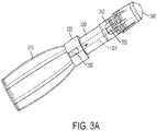
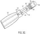
delivery tube 120 may contain porous material or materials to transmit the refrigerant from thecontainer 110 to thebud 140. Accordingly, the porous material(s) within thedelivery tube 120 may be the same or different from the material(s) that form thebud 140, as detailed below. Moreover, the porous material(s) may be provided along only a portion or portions of thedelivery tube 120. For example, as depicted in the exemplary embodiment ofFIG. 3A , the porous material(s) 350 may be provided within thelumen 321 at the first andsecond ends 322 and 324 with a middle portion of thedelivery tube 320 void of any porous material(s). In the exemplary embodiments ofFIGS. 3A-3B , the various parts of the systems are the same as are shown and described for the exemplary embodiment ofFIGS. 1-2 , but have been labeled with a 300 series of reference numerals. Alternatively, as depicted inFIG. 3B , only a middle portion of thelumen 321 of thedelivery tube 320 may include porous material(s) 350. Those having ordinary skill in the art will appreciate that various combinations of the placement ofporous materials 350 are considered within the scope of the present teachings, for example,porous material 350 may fill theentire lumen 321. In another exemplary embodiment, depicted inFIG. 3C , the porous material(s) 350 may be provided as a hollow tube concentrically disposed within thelumen 321 of thedelivery tube 320 such that a hollow pathway may be provided along a length of thedelivery tube 320 from thecontainer 310 to the bud 340. InFIGS. 3A-3C , other components of the cryo-surgical systems are the same as those shown and as described herein with reference toFIGS. 1 and2 and therefore are not specifically described herein. - In exemplary embodiments wherein porous material(s) fill a delivery lumen or are otherwise in contact with the applicator bud, the porous material(s), act as a reservoir to receive the refrigerant and to supply the bud with refrigerant. As the refrigerant evaporates from the bud, additional refrigerant is supplied from the porous material. In this manner, a wicking effect is created whereby the porous material feeds the bud with additional refrigerant as refrigerant from the outer surface of the bud evaporates. The refrigerant received and held by the porous material is predominantly, if not completely, in the liquid state. Supplying additional liquid refrigerant to the bud allows the bud to maintain its cold temperature for a longer period of time. This increases the depth and efficacy of freezing and, therefore, the cryosurgical treatment. This can be particularly useful for single-use cryosurgical devices. For a single-use cryosurgical device, the refrigerant can be discharged and increased duration of treatment may be achieved with exemplary embodiments including porous materials in conjunction with a bud.
- Exemplary refrigerants preferably have a boiling point at atmospheric pressure within a range from about 25 °C to about -120 °C, for example from about 0 °C to about -75 °C. Suitable refrigerants may include, but are not limited to, halogenated hydrocarbons (i.e.. tetrafluoromethane, trifluoromethane, monochlorotrifluoromethane, hexafluoroethane. monobromotrifluoromethane, monochlorodifluoromethane, monochloropentafluorothane, dichlorodifluoromethane, 1,2-dichloro-1,1,2,2-tetrafluoroethane, trichloromonofluoromethane, 1,1,2-trichloro-1,2,2-trifluoromethane and 1,1-difluoroethane), propane, n-butane, isobutane, dimethyl ether, and nitrogen. Dimethyl ether and alkanes, such as propane, are preferable for environmental reasons.
- With reference again to
FIG. 1 , thebud 140 includes afirst end portion 142 that insertably receives thedelivery tube 120, abody portion 144 disposed within thesecond end 124 of thedelivery tube 120, and asecond end portion 146 to extend from thesecond end 124 of thedelivery tube 120. Here, thebody portion 144 will be frictionally retained by thedelivery tube 120. For example, thedelivery tube 120 may comprisefinger portions 125 that flexibly fit around thebody portion 144. Thefinger portions 125 may be flexible to permit substantially elastic movement of thefinger portions 125 inwardly and outwardly (i.e., toward and away from the bud 140). The contact surface of thesecond end portion 146 may have a maximum, uncompressed diameter of about 5 mm, but may be increased or reduced based upon the size of the lesion to be treated. - The
bud 140 is formed of a porous material or materials. For example, thebud 140 is composed of cotton wool, open-celled foams, and polyolefin or polyester non-woven fabrics. Here, the material(s) of thebud 140 do not react chemically with the refrigerant and has suitable physical properties throughout the range of temperatures to which thebud 140 is exposed during use, for example, from about 25 °C to about -120 °C. - The density of the material(s) is preferably less than about 60 kg/m3, and preferably within a range of about 10 kg/m3 to about 40 kg/m3, and more preferably within a range of about 12 kg/m3 to about 35 kg/m3, and even more preferably within a range of about 26 kg/m3 to about 32 kg/m3. The pore size of the
bud 140 is preferably within a range of about 5 pores/cm to about 50 pores/cm, and preferably within a range of about 20 pores/cm to about 40 pores/cm, and more preferably within a range of about 30 pores/cm to about 40 pores/cm, and even more preferably within a range of about 27 pores/cm to about 32 pores/cm. - The
bud 140 may be formed from suitable foam-type polymer material(s) including, but not limited to, polyesters, polyethers, polyurethanes, polyethylene, polypropylene, phenolic resins, polystyrenes and polyvinyl chloride resins, and in particular, polyester-based polyurethanes. Preferably, the foam-type material(s) is composed of a polymer that is wettable by the refrigerant, thereby quickly obtaining lower treatment temperatures and/or increased effective treatment times. Open-celled foam materials are preferred. - The
bud 140 also may comprise layers of porous materials, for example, layers of differing porous materials. - According to an exemplary teaching the
bud 140 may also include an internal cavity. When the refrigerant is provided to thebud 140, the foam material(s) is subject to internal pressure from the refrigerant and may be subject to external pressure when pressed against the targeted treatment area of the lesion. Accordingly, the wall thickness of thebud 140 should be selected accordingly. In addition, the cavity may be filled, at least in part if not entirely, with a suitable permeable and absorbent solid material or materials. The material(s) modifies and controls the pressure and flow of the refrigerant into the interior cavity of thebud 140 so that the cooling effect is more uniform and more reproducible. For example, cotton wool may be placed within the cavity of thebud 140 due to its permeability and absorbency. In addition, other materials, including other non-woven fibrous cellulosic or non-cellulosic materials could also be used. The presence of the cotton wool or other permeable material can also improve the physical strength of thebud 140. The cotton wool or other material(s) provided within the cavity of thebud 140 may fill the cavity in order to make direct contact with the walls of the cavity, thereby providing physical support to thebud 140. This type of bud is described in Jensma,U.S. Patent 6,387,090 ,. - Although not specifically shown, the
bud 140 and/or the plurality offinger portions 125 may also include a protective wrapper or cover to maintain integrity of thesystem 100. Accordingly, prior to using thesystem 100, the user may remove the wrapper before attaching thedelivery tube 120 to thecontainer 110. FIG. 2 is a perspective view of the exemplary cryo-surgical system ofFIG. 1 used in the method according to the present invention. InFIG. 2 , theadjustment ring 130 is positioned toward thesecond end 124 of thedelivery tube 120. Here, theadjustment ring 130 includes an internal threadedportion 132 which engages external threads of thesecond end 126 of thedelivery tube 120. Since the inner diameter of theadjustment ring 130 is smaller than the outer diameter of thedelivery tube 120, theadjustment ring 130 may be slid into position with respect to thefinger portions 125. As theadjustment ring 130 is tightened along the external threads of thesecond end 126 of thedelivery tube 120, theadjustment ring 130 travels toward thefinger portions 125. Accordingly, theadjustment ring 130 causes thefinger portions 125 to close around thebody portion 144 andsecond end portion 146 of thebud 140, thereby compressing thebody portion 144 and thesecond end portion 146 and reducing a contact surface of thesecond end portion 146 of thebud 140. Thus, thecontact surface 146 may be reduced using theadjustment ring 130 to treat a relatively small targeted treatment area of a lesion. Conversely, the contact surface of thesecond end portion 146 of thebud 140 may be maximized by merely tightening theadjustment ring 130 snuggly so as to not compress thebud 140 using thefinger portions 125 in order to treat a larger targeted lesion or treatment area of a lesion. As a result, thebud 140 may be adjusted to provide for treatment of relatively large and small targeted lesion or treatment areas of a lesion by tightening or loosening theadjustment ring 130.- Alternatively, the
adjustment ring 130 may be fractionally fit to thefinger portions 125 such that theinternal threads 132 of theadjustment ring 130 and the external threads at thesecond end 126 of thedelivery tube 120 are not necessary in order to compress thebud 140, - In another exemplary embodiment, illustrated in
FIG. 4 , anadjustment ring 430 having a configuration similar toadjustment ring 130 may be attached to the upper end 424 of thedelivery tube 420proximate finger portions 425. Theadjustment ring 430 may be attached to thedelivery tube 420 via a spring 435 (shown underneath theadjustment ring 430 inFIG. 4 ). When it is desired to increase the size of thebud 440, theadjustment ring 430 may be moved in a direction toward thecontainer 410, thereby compressing thespring 435 toward the container and permitting theadjustment fingers 425 to open outwardly, at least partially removing the compression forces from thebody portion 444 andsecond end portion 446 of thebud 440. When it is desired to decrease the size of thebud 440, theadjustment ring 430 may be moved in a direction toward thebud 440, thereby compressingspring 435 and engaging theadjustment ring 430 with thefinger portions 425. This will cause thefinger portions 425 to close around thebody portion 444 and potentially some of thesecond end portion 446 of thebud 440, thereby compressing thebody portion 444 and thesecond end portion 446 and reducing a contact surface of thesecond end portion 446 of thebud 440. In another exemplary configuration, theadjustment ring 430 may be either spring-biased in a direction so as to be in engagement with thefinger portions 425 so as to compress thebud 440 and if a larger bud size is desired, theadjustment ring 430 may be moved toward thecontainer 410 to release thefinger portions 425 to the extent desired. In yet another exemplary configuration, theadjustment ring 430 may be spring-biased toward thecontainer 410 and out of engagement with thefinger portions 425 so as to render thebud 440 in an uncompressed, larger configuration, and if desired, theadjustment ring 430 may be moved into engagement with theadjustment fingers 425 by compressing thespring 435 to compress thebud 440. Aside from the operability and configuration of the adjustment ring, remaining components of the cryo-surgical system ofFIG. 4 are the same as those shown and as described herein with reference toFIGS. 1 and2 and therefore are not specifically described herein. - According to the present teachings the exemplary cryo-surgical systems described herein may also include a plurality of different sized buds to provide the user with improved flexibility for treating a substantially large range of targeted lesions or treatment areas of lesions. Here, the user may select the appropriate size bud based upon the approximate size of the lesion of targeted treatment area of the lesion.
- In addition, the exemplary cryo-
surgical system 100 may also include different sized buds to provide withindividual delivery tubes 120 to further provide the user with improved flexibility for treating a substantially large range of targeted lesions or treatment areas of lesions. Here, the user may select theappropriate delivery tube 120 having the specific size bud based upon the approximate size of the targeted lesion or treatment area of the lesion. Similarly, the contact surface of thesecond end portion 146 of thebud 140 may have different geometrical configurations, such as conical, chisel, or cylindrical geometries. - Furthermore, the
delivery tube 120 may be formed not only as a linear cylindrical tube, but may include a curved offset portion or portions to provide the user with the ability to treat hard-to-reach lesion locations, such as the back, lower leg, shoulder, etc. For example, thedelivery tube 120 may have a first portion extending along a first direction from thecontainer 110 and a second portion or portions extending along a second direction at an angle from the first direction. Moreover, thedelivery tube 120 may have a U-shaped or J-shaped configuration. In addition, thedelivery tube 120 may be formed having flexible portions, or flexible along an entire length of thedelivery tube 120, to allow the user to shape thedelivery tube 120 for easy treatment of lesion locations. - According to the present teaching, the
bud 140 may be formed of various materials that provide for absorption and flow of the refrigerant from thecontainer 110. Here, thebud 140 may be formed of a single material, or may be formed of multiple materials, as detailed above. For example, thefirst end portion 142, thebody portion 144 and the contact surface of thesecond end portion 146 may be formed of a single-density foam. Alternatively, thefirst end portion 142 may be formed of a first density foam, thebody portion 144 may be formed of a second density foam, and the contact surface of thesecond end portion 146 may be formed of a third density foam, wherein each of the first second, and third densities may be substantially different. Moreover, thefirst end portion 142 may be formed of a first density foam, and thebody portion 144 and the contact surface of thesecond end portion 146 may be formed of a second density foam, wherein the first and densities may be substantially different. These configurations may also apply to buds of the other exemplary embodiments shown and described herein. - According to the present teaching treatment of a lesion is not limited to lesions located on exterior surfaces of the body. Specifically, the present teaching may be used to treat lesions in cavities in the body. Accordingly, an overall length of the
delivery tube 120 may be adjusted using an extendible coupling or mechanism to treat lesions or tissues deep inside the human body. Here, the flow of the refrigerant from thecontainer 110 may need to be initiated after thebud 140 is positioned against the lesion or tissue to be treated in order to prevent damaging healthy tissue disposed along the pathway between the lesion or tissue to be treated and the point of entry into the cavity of thedelivery tube 120. For, the flow of refrigerant from thecontainer 110 may be commenced once the contact surface of thesecond end portion 146 of thebud 140 is in proper position to treat the lesion or tissue. Here, a rupturing mechanism (not shown) may be incorporated into thefirst end portion 122 of thedelivery tube 120 to allow the user to initiate flow of the refrigerant from within thecontainer 110, through thedelivery tube 120, and through thebud 140 to the contact surface of thesecond end portion 146 after positioning thebud 140 against the lesion or tissue to be treated. As above, such configurations may apply to the exemplary embodiments and corresponding components of other of the exemplary embodiments shown and described herein. - Although various exemplary embodiments of the present teachings have been described as not including a valving mechanism, those having ordinary skill in the art will appreciate that a valving mechanism may be used if desired with any of the exemplary embodiments of
FIGS. 1-4 . and may be desirable in situations where a high pressure, flammable refrigerant in used.FIGS. 5 and 6 depict another exemplary embodiment of acryosurgical system 500 that utilizes avalving mechanism 575 to permit or stop the flow of the refrigerant from acontainer 510 containing the refrigerant to adelivery tube 520 defining adelivery lumen 521 and ultimately to abud 540. With reference to the perspective view ofFIG. 5 , thedevice 500 may be provided with anactuation mechanism 580 configured to be pulled or depressed toward an end of thedevice 500 opposite thebud 540 to place thevalving mechanism 575 in an open position to permit flow of the refrigerant from thecontainer 510 through thevalving mechanism 575 and into thedelivery lumen 521. Thevalving mechanism 575 may be any type of conventional valving mechanisms configured to provide such flow control with which those ordinarily skilled in the art have familiarity. In one exemplary configuration, theactuation member 580 may be locked into the depressed position. However, other configurations contemplate that theactuation member 580 may be spring-biased toward the position closing thevalving mechanism 575 and operated in a manner similar to a trigger-type of valve mechanism on other known containers for dispensing fluids, for example, by a user having to continually apply force to theactuation member 580 to maintain theactuation member 580 in the position that opens thevalving mechanism 575.. - Those having skill in the art will also appreciate that in the exemplary embodiment depicted in
FIG. 6 , to dispense the fluid from thecontainer 510, thecontainer 510 needs to be inverted. However, as those ordinarily skilled in the art will appreciate, a dip tube could be provided from the end of the valving mechanism and extending into the container if dispensing of the refrigerant is desired while leaving thecontainer 510 in a non-inverted position (i.e., in the position depicted inFIGS. 5 and 6 ). - As shown in
FIG. 6 , thedelivery tube 520 may open up into atube 525 of larger outer and internal dimensions and that is filled with porous material(s) 550. The porous material(s) 550 may be used in the manner described for theporous materials 350 described above with reference to the exemplary embodiments ofFIGS. 3A-3C , that is, to store and flow refrigerant to the bud 540 (e.g., via a wicking type of effect) as refrigerant evaporates from thebud 540. - Referring now to
FIG. 7 , another exemplary embodiment of a cryosurgical system 700 is depicted. The system 700 has a similar configuration to that ofFIGS. 5 and 6 , (with like parts being labeled with like reference numerals except with a 700 series), with the exception that the system 700 includesadjustable finger portions 725 and anadjustment ring 730 that may operate and have a configuration similar to that described with reference to the exemplary embodiments ofFIGS. 1 ,2 and4 to adjust the size of thebud 740 andsecond end portion 746. - The exemplary embodiments of
FIGS. 5-7 , like those ofFIGS. 1-4 , can be configured as single-use devices, In various exemplary embodiments, thecontainers containers bud bud - Although the present invention has been described in relation to particular embodiments thereof, many other variations and modifications and other uses will become apparent to those skilled in the art. Those having ordinary skill in the art will understand that various modifications can be made to sizes, materials, arrangements, and types of parts without departing from the scope of the present teachings. Moreover, although some features described herein may have been described in the context of a particular exemplary embodiment, those ordinarily skilled in the art will appreciate that various features of different exemplary embodiments may be combined with other exemplary embodiments. It is intended therefore, that the present teachings be limited not by the specific disclosure herein and that the claims be entitled to their full scope.
Claims (6)
- A method for dispensing a refrigerant in a cryosurgical system, the method comprising:providing a cryosurgical system with a container (110, 310, 410, 710) containing a refrigerant and a delivery tube (120, 320, 420, 720) having a first end (122, 322, 422) configured to be in flow communication with the container and a second end (124, 324, 424) opposite the first end, and a porous applicator bud (140, 340, 440, 740) disposed proximate the second end;adjusting a size of the porous applicator bud by at least partially removing compression forces of flexible finger portions on the porous applicator bud to increase the size of the contact surface (146, 346, 446, 746) of the porous applicator bud or engaging an adjustment ring (130, 330, 430, 730) with the flexible finger portions and thereby compressing a surface of the porous applicator bud to decrease the size of the contact surface of the porous applicator bud; anddelivering refrigerant from the container to the applicator bud.
- The method for dispensing a refrigerant according to claim 1 further comprising:
coupling the delivery tube to the container to place a lumen (121, 321, 721) of the delivery tube in flow communication with the refrigerant in the container. - The method for dispensing a refrigerant according to claim 2, wherein coupling the delivery tube to the container comprises penetrating a sealing surface of the container.
- The method for dispensing a refrigerant according to claim 1, wherein engaging the adjustment ring with the finger portions (125, 325, 425, 725) includes threadingly engaging a threaded portion of the adjustment ring with a threaded portion on the delivery tube.
- The method for dispensing a refrigerant according to claim 1, wherein delivering the refrigerant from the container to the applicator bud comprises delivering the refrigerant from the container to the applicator bud without using an intervening valving mechanism therebetween.
- The method for dispensing a refrigerant according to claim 1, wherein delivering the refrigerant from the container to the applicator bud comprises storing the refrigerant from the container in a porous material (350) and supplying the stored refrigerant from the porous material to the applicator bud.
Applications Claiming Priority (3)
| Application Number | Priority Date | Filing Date | Title |
|---|---|---|---|
| US6054208P | 2008-06-11 | 2008-06-11 | |
| EP09763584.1AEP2309938B1 (en) | 2008-06-11 | 2009-06-11 | Cryo-surgical systems |
| PCT/US2009/046989WO2009152294A2 (en) | 2008-06-11 | 2009-06-11 | Cryo-surgical systems and methods of using the same |
Related Parent Applications (1)
| Application Number | Title | Priority Date | Filing Date |
|---|---|---|---|
| EP09763584.1ADivisionEP2309938B1 (en) | 2008-06-11 | 2009-06-11 | Cryo-surgical systems |
Publications (2)
| Publication Number | Publication Date |
|---|---|
| EP2837348A1 EP2837348A1 (en) | 2015-02-18 |
| EP2837348B1true EP2837348B1 (en) | 2020-04-08 |
Family
ID=41417393
Family Applications (2)
| Application Number | Title | Priority Date | Filing Date |
|---|---|---|---|
| EP14180657.0AActiveEP2837348B1 (en) | 2008-06-11 | 2009-06-11 | Cryo-surgical methods of use |
| EP09763584.1AActiveEP2309938B1 (en) | 2008-06-11 | 2009-06-11 | Cryo-surgical systems |
Family Applications After (1)
| Application Number | Title | Priority Date | Filing Date |
|---|---|---|---|
| EP09763584.1AActiveEP2309938B1 (en) | 2008-06-11 | 2009-06-11 | Cryo-surgical systems |
Country Status (7)
| Country | Link |
|---|---|
| US (2) | US8906005B2 (en) |
| EP (2) | EP2837348B1 (en) |
| CN (1) | CN102065785B (en) |
| CA (1) | CA2727540C (en) |
| DK (2) | DK2837348T3 (en) |
| ES (2) | ES2520116T3 (en) |
| WO (1) | WO2009152294A2 (en) |
Families Citing this family (17)
| Publication number | Priority date | Publication date | Assignee | Title |
|---|---|---|---|---|
| EP2837348B1 (en) | 2008-06-11 | 2020-04-08 | CryoConcepts LP | Cryo-surgical methods of use |
| US20110152850A1 (en)* | 2009-06-23 | 2011-06-23 | Niedbala R Sam | Devices and methods for dispensing a cryogenic fluid |
| US8647337B2 (en)* | 2009-06-23 | 2014-02-11 | Stc Consulting, Llc | Devices and methods for dispensing a cryogenic fluid |
| JP6193850B2 (en) | 2011-06-19 | 2017-09-06 | アボゲン,インコーポレイティド | Devices, solutions and methods for sample collection |
| AU2014209951A1 (en)* | 2013-01-25 | 2015-08-27 | Youmedical Brands B.V. | Device for non-surgical cold treatment of disorders |
| WO2017096212A1 (en)* | 2015-12-03 | 2017-06-08 | Ice Shot, Llc. | Portable, personal, reusable, cryotherapy unit including a pre-injection site dermal numbing and marking unit and method of using the same |
| PL3360496T3 (en)* | 2017-02-10 | 2022-06-06 | Erbe Elektromedizin Gmbh | Fluid connection device and cryosurgical probe having same |
| NZ757589A (en) | 2017-03-15 | 2017-09-27 | Ancestry Com Dna Llc | Sample collection device and method |
| EP3691538A4 (en) | 2017-10-06 | 2021-06-30 | Ancestry.com DNA, LLC | Systems, devices, and methods for sample collection |
| US11426734B2 (en) | 2017-11-22 | 2022-08-30 | Ancestry.Com Dna, Llc | Sample collection kit including cap having selectively movable sleeve |
| AU2018373247B2 (en) | 2017-11-22 | 2023-11-30 | Ancestry. Com Dna, Llc | Sample collection kit including cap having selectively movable sleeve |
| EP4154832B1 (en) | 2018-04-27 | 2024-05-22 | Recensmedical, Inc. | Cooling apparatus and cooling method |
| EP3897428B1 (en) | 2018-12-17 | 2024-04-17 | CryoConcepts LP | Flow modulation device for dispensing pressurized fluids |
| US11482306B2 (en) | 2019-02-27 | 2022-10-25 | Ancestry.Com Dna, Llc | Graphical user interface displaying relatedness based on shared DNA |
| USD1015533S1 (en) | 2019-11-07 | 2024-02-20 | 623 Medical, Llc | Vapocoolant device |
| USD913508S1 (en)* | 2020-03-06 | 2021-03-16 | Cryoconcepts Lp | Device for dispensing carbon dioxide enhanced topical substances |
| US12332902B2 (en) | 2022-04-20 | 2025-06-17 | Ancestry.Com Dna, Llc | Filtering individual datasets in a database |
Family Cites Families (19)
| Publication number | Priority date | Publication date | Assignee | Title |
|---|---|---|---|---|
| US4022215A (en)* | 1973-12-10 | 1977-05-10 | Benson Jerrel W | Cryosurgical system |
| US4015606A (en)* | 1975-09-09 | 1977-04-05 | Dynatech Corporation | Method and means for controlling the freeze zone of a cryosurgical probe |
| US5516505A (en) | 1989-07-18 | 1996-05-14 | Mcdow; Ronald A. | Method for using cryogenic agents for treating skin lesions |
| NO308722B1 (en) | 1993-01-29 | 2000-10-23 | Stc Technologies Inc | Surface cooling device and applicator |
| AU770243B2 (en)* | 1999-04-09 | 2004-02-19 | Evalve, Inc. | Methods and apparatus for cardiac valve repair |
| US7381207B2 (en)* | 2003-06-25 | 2008-06-03 | Endocare, Inc. | Quick disconnect assembly having a finger lock assembly |
| US7160291B2 (en)* | 2003-06-25 | 2007-01-09 | Endocare, Inc. | Detachable cryosurgical probe |
| US20050043723A1 (en)* | 2003-08-19 | 2005-02-24 | Schering-Plough Healthcare Products, Inc. | Cryosurgery device |
| AU2004308417B2 (en)* | 2003-12-22 | 2010-04-08 | Ams Research Corporation | Cryosurgical devices for endometrial ablation |
| DK1827274T3 (en)* | 2004-09-17 | 2013-10-14 | Orasure Technologies Inc | Cryosurgery device and method for delivering a liquid refrigerant |
| US20070016272A1 (en)* | 2004-09-27 | 2007-01-18 | Thompson Russell B | Systems and methods for treating a hollow anatomical structure |
| US20060271032A1 (en)* | 2005-05-26 | 2006-11-30 | Chin Albert K | Ablation instruments and methods for performing abalation |
| WO2007005523A2 (en)* | 2005-06-30 | 2007-01-11 | Stc Consulting, Llc | Method and apparatus for cryogenically treating lesions on biological tissue |
| US7842032B2 (en)* | 2005-10-13 | 2010-11-30 | Bacoustics, Llc | Apparatus and methods for the selective removal of tissue |
| US7799018B2 (en)* | 2006-01-06 | 2010-09-21 | Olga Goulko | Cryogenic applicator for rejuvenating human skin and related method |
| NL1031888C2 (en)* | 2006-05-25 | 2007-11-27 | Konink Utermoehlen N V | Device, assembly and method for treating a tissue with cold. |
| US20080119839A1 (en)* | 2006-11-21 | 2008-05-22 | Vancelette David W | Cryosurgical Applicator |
| WO2009065061A1 (en)* | 2007-11-14 | 2009-05-22 | Myoscience, Inc. | Pain management using cryogenic remodeling |
| EP2837348B1 (en)* | 2008-06-11 | 2020-04-08 | CryoConcepts LP | Cryo-surgical methods of use |
- 2009
- 2009-06-11EPEP14180657.0Apatent/EP2837348B1/enactiveActive
- 2009-06-11DKDK14180657.0Tpatent/DK2837348T3/enactive
- 2009-06-11EPEP09763584.1Apatent/EP2309938B1/enactiveActive
- 2009-06-11WOPCT/US2009/046989patent/WO2009152294A2/enactiveApplication Filing
- 2009-06-11ESES09763584.1Tpatent/ES2520116T3/enactiveActive
- 2009-06-11DKDK09763584.1Tpatent/DK2309938T3/enactive
- 2009-06-11CACA2727540Apatent/CA2727540C/enactiveActive
- 2009-06-11USUS12/997,056patent/US8906005B2/enactiveActive
- 2009-06-11ESES14180657Tpatent/ES2787354T3/enactiveActive
- 2009-06-11CNCN2009801221032Apatent/CN102065785B/enactiveActive
- 2014
- 2014-12-05USUS14/561,335patent/US9757179B2/enactiveActive
Non-Patent Citations (1)
| Title |
|---|
| None* |
Also Published As
| Publication number | Publication date |
|---|---|
| DK2309938T3 (en) | 2014-11-10 |
| EP2309938A2 (en) | 2011-04-20 |
| EP2837348A1 (en) | 2015-02-18 |
| CN102065785A (en) | 2011-05-18 |
| US9757179B2 (en) | 2017-09-12 |
| ES2520116T3 (en) | 2014-11-11 |
| WO2009152294A3 (en) | 2010-03-25 |
| US20150201989A1 (en) | 2015-07-23 |
| CA2727540A1 (en) | 2009-12-17 |
| CN102065785B (en) | 2013-06-12 |
| CA2727540C (en) | 2016-11-22 |
| ES2787354T3 (en) | 2020-10-15 |
| DK2837348T3 (en) | 2020-05-04 |
| EP2309938A4 (en) | 2012-07-18 |
| EP2309938B1 (en) | 2014-08-13 |
| WO2009152294A2 (en) | 2009-12-17 |
| US20110152851A1 (en) | 2011-06-23 |
| US8906005B2 (en) | 2014-12-09 |
Similar Documents
| Publication | Publication Date | Title |
|---|---|---|
| EP2837348B1 (en) | Cryo-surgical methods of use | |
| US7604632B2 (en) | Cryosurgery device | |
| RU2123813C1 (en) | Device and applicator for distribution of liquid cooling agent, skin cooling method | |
| US4082096A (en) | Cryosurgical system | |
| US5516505A (en) | Method for using cryogenic agents for treating skin lesions | |
| EP2468204B1 (en) | Cryogenic fluid dispensing device | |
| CA2580471C (en) | Cryosurgical device and method for cooling surfaces | |
| EP2124791B1 (en) | Dispensing device for pressurized containers for the application of cryogenic coolant | |
| HK74395A (en) | Device for carrying out a therapeutic treatment by means of a refrigerant | |
| US8647337B2 (en) | Devices and methods for dispensing a cryogenic fluid | |
| US11154874B2 (en) | Flow modulation device for dispensing pressurized fluids | |
| WO2013132357A1 (en) | Dispensing device for pressurized containers for the application of cryogenic coolant | |
| CN100581496C (en) | Cryosurgical device and method for cooling surfaces |
Legal Events
| Date | Code | Title | Description |
|---|---|---|---|
| 17P | Request for examination filed | Effective date:20140812 | |
| AC | Divisional application: reference to earlier application | Ref document number:2309938 Country of ref document:EP Kind code of ref document:P | |
| AK | Designated contracting states | Kind code of ref document:A1 Designated state(s):AT BE BG CH CY CZ DE DK EE ES FI FR GB GR HR HU IE IS IT LI LT LU LV MC MK MT NL NO PL PT RO SE SI SK TR | |
| PUAI | Public reference made under article 153(3) epc to a published international application that has entered the european phase | Free format text:ORIGINAL CODE: 0009012 | |
| R17P | Request for examination filed (corrected) | Effective date:20150818 | |
| RBV | Designated contracting states (corrected) | Designated state(s):AT BE BG CH CY CZ DE DK EE ES FI FR GB GR HR HU IE IS IT LI LT LU LV MC MK MT NL NO PL PT RO SE SI SK TR | |
| GRAP | Despatch of communication of intention to grant a patent | Free format text:ORIGINAL CODE: EPIDOSNIGR1 | |
| STAA | Information on the status of an ep patent application or granted ep patent | Free format text:STATUS: GRANT OF PATENT IS INTENDED | |
| INTG | Intention to grant announced | Effective date:20190927 | |
| GRAS | Grant fee paid | Free format text:ORIGINAL CODE: EPIDOSNIGR3 | |
| GRAJ | Information related to disapproval of communication of intention to grant by the applicant or resumption of examination proceedings by the epo deleted | Free format text:ORIGINAL CODE: EPIDOSDIGR1 | |
| GRAL | Information related to payment of fee for publishing/printing deleted | Free format text:ORIGINAL CODE: EPIDOSDIGR3 | |
| STAA | Information on the status of an ep patent application or granted ep patent | Free format text:STATUS: REQUEST FOR EXAMINATION WAS MADE | |
| GRAR | Information related to intention to grant a patent recorded | Free format text:ORIGINAL CODE: EPIDOSNIGR71 | |
| STAA | Information on the status of an ep patent application or granted ep patent | Free format text:STATUS: GRANT OF PATENT IS INTENDED | |
| GRAA | (expected) grant | Free format text:ORIGINAL CODE: 0009210 | |
| STAA | Information on the status of an ep patent application or granted ep patent | Free format text:STATUS: THE PATENT HAS BEEN GRANTED | |
| RAP1 | Party data changed (applicant data changed or rights of an application transferred) | Owner name:CRYOCONCEPTS LP | |
| INTC | Intention to grant announced (deleted) | ||
| AC | Divisional application: reference to earlier application | Ref document number:2309938 Country of ref document:EP Kind code of ref document:P | |
| AK | Designated contracting states | Kind code of ref document:B1 Designated state(s):AT BE BG CH CY CZ DE DK EE ES FI FR GB GR HR HU IE IS IT LI LT LU LV MC MK MT NL NO PL PT RO SE SI SK TR | |
| INTG | Intention to grant announced | Effective date:20200228 | |
| REG | Reference to a national code | Ref country code:CH Ref legal event code:EP Ref country code:AT Ref legal event code:REF Ref document number:1253305 Country of ref document:AT Kind code of ref document:T Effective date:20200415 | |
| REG | Reference to a national code | Ref country code:DE Ref legal event code:R096 Ref document number:602009061708 Country of ref document:DE | |
| REG | Reference to a national code | Ref country code:IE Ref legal event code:FG4D | |
| REG | Reference to a national code | Ref country code:DK Ref legal event code:T3 Effective date:20200428 | |
| REG | Reference to a national code | Ref country code:NL Ref legal event code:FP | |
| REG | Reference to a national code | Ref country code:SE Ref legal event code:TRGR | |
| REG | Reference to a national code | Ref country code:LT Ref legal event code:MG4D | |
| REG | Reference to a national code | Ref country code:ES Ref legal event code:FG2A Ref document number:2787354 Country of ref document:ES Kind code of ref document:T3 Effective date:20201015 | |
| PG25 | Lapsed in a contracting state [announced via postgrant information from national office to epo] | Ref country code:GR Free format text:LAPSE BECAUSE OF FAILURE TO SUBMIT A TRANSLATION OF THE DESCRIPTION OR TO PAY THE FEE WITHIN THE PRESCRIBED TIME-LIMIT Effective date:20200709 Ref country code:NO Free format text:LAPSE BECAUSE OF FAILURE TO SUBMIT A TRANSLATION OF THE DESCRIPTION OR TO PAY THE FEE WITHIN THE PRESCRIBED TIME-LIMIT Effective date:20200708 Ref country code:PT Free format text:LAPSE BECAUSE OF FAILURE TO SUBMIT A TRANSLATION OF THE DESCRIPTION OR TO PAY THE FEE WITHIN THE PRESCRIBED TIME-LIMIT Effective date:20200817 Ref country code:LT Free format text:LAPSE BECAUSE OF FAILURE TO SUBMIT A TRANSLATION OF THE DESCRIPTION OR TO PAY THE FEE WITHIN THE PRESCRIBED TIME-LIMIT Effective date:20200408 Ref country code:IS Free format text:LAPSE BECAUSE OF FAILURE TO SUBMIT A TRANSLATION OF THE DESCRIPTION OR TO PAY THE FEE WITHIN THE PRESCRIBED TIME-LIMIT Effective date:20200808 Ref country code:FI Free format text:LAPSE BECAUSE OF FAILURE TO SUBMIT A TRANSLATION OF THE DESCRIPTION OR TO PAY THE FEE WITHIN THE PRESCRIBED TIME-LIMIT Effective date:20200408 | |
| PG25 | Lapsed in a contracting state [announced via postgrant information from national office to epo] | Ref country code:HR Free format text:LAPSE BECAUSE OF FAILURE TO SUBMIT A TRANSLATION OF THE DESCRIPTION OR TO PAY THE FEE WITHIN THE PRESCRIBED TIME-LIMIT Effective date:20200408 Ref country code:BG Free format text:LAPSE BECAUSE OF FAILURE TO SUBMIT A TRANSLATION OF THE DESCRIPTION OR TO PAY THE FEE WITHIN THE PRESCRIBED TIME-LIMIT Effective date:20200708 Ref country code:LV Free format text:LAPSE BECAUSE OF FAILURE TO SUBMIT A TRANSLATION OF THE DESCRIPTION OR TO PAY THE FEE WITHIN THE PRESCRIBED TIME-LIMIT Effective date:20200408 | |
| REG | Reference to a national code | Ref country code:DE Ref legal event code:R097 Ref document number:602009061708 Country of ref document:DE | |
| PG25 | Lapsed in a contracting state [announced via postgrant information from national office to epo] | Ref country code:MC Free format text:LAPSE BECAUSE OF FAILURE TO SUBMIT A TRANSLATION OF THE DESCRIPTION OR TO PAY THE FEE WITHIN THE PRESCRIBED TIME-LIMIT Effective date:20200408 Ref country code:CZ Free format text:LAPSE BECAUSE OF FAILURE TO SUBMIT A TRANSLATION OF THE DESCRIPTION OR TO PAY THE FEE WITHIN THE PRESCRIBED TIME-LIMIT Effective date:20200408 Ref country code:RO Free format text:LAPSE BECAUSE OF FAILURE TO SUBMIT A TRANSLATION OF THE DESCRIPTION OR TO PAY THE FEE WITHIN THE PRESCRIBED TIME-LIMIT Effective date:20200408 Ref country code:EE Free format text:LAPSE BECAUSE OF FAILURE TO SUBMIT A TRANSLATION OF THE DESCRIPTION OR TO PAY THE FEE WITHIN THE PRESCRIBED TIME-LIMIT Effective date:20200408 | |
| REG | Reference to a national code | Ref country code:CH Ref legal event code:PL | |
| PLBE | No opposition filed within time limit | Free format text:ORIGINAL CODE: 0009261 | |
| STAA | Information on the status of an ep patent application or granted ep patent | Free format text:STATUS: NO OPPOSITION FILED WITHIN TIME LIMIT | |
| PG25 | Lapsed in a contracting state [announced via postgrant information from national office to epo] | Ref country code:SK Free format text:LAPSE BECAUSE OF FAILURE TO SUBMIT A TRANSLATION OF THE DESCRIPTION OR TO PAY THE FEE WITHIN THE PRESCRIBED TIME-LIMIT Effective date:20200408 Ref country code:PL Free format text:LAPSE BECAUSE OF FAILURE TO SUBMIT A TRANSLATION OF THE DESCRIPTION OR TO PAY THE FEE WITHIN THE PRESCRIBED TIME-LIMIT Effective date:20200408 | |
| 26N | No opposition filed | Effective date:20210112 | |
| PG25 | Lapsed in a contracting state [announced via postgrant information from national office to epo] | Ref country code:IE Free format text:LAPSE BECAUSE OF NON-PAYMENT OF DUE FEES Effective date:20200611 Ref country code:LI Free format text:LAPSE BECAUSE OF NON-PAYMENT OF DUE FEES Effective date:20200630 Ref country code:CH Free format text:LAPSE BECAUSE OF NON-PAYMENT OF DUE FEES Effective date:20200630 | |
| PG25 | Lapsed in a contracting state [announced via postgrant information from national office to epo] | Ref country code:SI Free format text:LAPSE BECAUSE OF FAILURE TO SUBMIT A TRANSLATION OF THE DESCRIPTION OR TO PAY THE FEE WITHIN THE PRESCRIBED TIME-LIMIT Effective date:20200408 | |
| PG25 | Lapsed in a contracting state [announced via postgrant information from national office to epo] | Ref country code:TR Free format text:LAPSE BECAUSE OF FAILURE TO SUBMIT A TRANSLATION OF THE DESCRIPTION OR TO PAY THE FEE WITHIN THE PRESCRIBED TIME-LIMIT Effective date:20200408 Ref country code:MT Free format text:LAPSE BECAUSE OF FAILURE TO SUBMIT A TRANSLATION OF THE DESCRIPTION OR TO PAY THE FEE WITHIN THE PRESCRIBED TIME-LIMIT Effective date:20200408 Ref country code:CY Free format text:LAPSE BECAUSE OF FAILURE TO SUBMIT A TRANSLATION OF THE DESCRIPTION OR TO PAY THE FEE WITHIN THE PRESCRIBED TIME-LIMIT Effective date:20200408 | |
| PG25 | Lapsed in a contracting state [announced via postgrant information from national office to epo] | Ref country code:MK Free format text:LAPSE BECAUSE OF FAILURE TO SUBMIT A TRANSLATION OF THE DESCRIPTION OR TO PAY THE FEE WITHIN THE PRESCRIBED TIME-LIMIT Effective date:20200408 | |
| PGFP | Annual fee paid to national office [announced via postgrant information from national office to epo] | Ref country code:GB Payment date:20240627 Year of fee payment:16 | |
| PGFP | Annual fee paid to national office [announced via postgrant information from national office to epo] | Ref country code:DE Payment date:20240627 Year of fee payment:16 | |
| PGFP | Annual fee paid to national office [announced via postgrant information from national office to epo] | Ref country code:DK Payment date:20240625 Year of fee payment:16 | |
| PGFP | Annual fee paid to national office [announced via postgrant information from national office to epo] | Ref country code:AT Payment date:20240620 Year of fee payment:16 | |
| PGFP | Annual fee paid to national office [announced via postgrant information from national office to epo] | Ref country code:FR Payment date:20240625 Year of fee payment:16 | |
| PGFP | Annual fee paid to national office [announced via postgrant information from national office to epo] | Ref country code:SE Payment date:20240627 Year of fee payment:16 Ref country code:BE Payment date:20240627 Year of fee payment:16 | |
| PGFP | Annual fee paid to national office [announced via postgrant information from national office to epo] | Ref country code:IT Payment date:20240619 Year of fee payment:16 | |
| REG | Reference to a national code | Ref country code:AT Ref legal event code:UEP Ref document number:1253305 Country of ref document:AT Kind code of ref document:T Effective date:20200408 | |
| PGFP | Annual fee paid to national office [announced via postgrant information from national office to epo] | Ref country code:LU Payment date:20250728 Year of fee payment:17 Ref country code:NL Payment date:20250726 Year of fee payment:17 | |
| PGFP | Annual fee paid to national office [announced via postgrant information from national office to epo] | Ref country code:ES Payment date:20250801 Year of fee payment:17 |