EP2837347B1 - Bone anchoring device - Google Patents
Bone anchoring deviceDownload PDFInfo
- Publication number
- EP2837347B1 EP2837347B1EP14192707.9AEP14192707AEP2837347B1EP 2837347 B1EP2837347 B1EP 2837347B1EP 14192707 AEP14192707 AEP 14192707AEP 2837347 B1EP2837347 B1EP 2837347B1
- Authority
- EP
- European Patent Office
- Prior art keywords
- pressure member
- bone anchoring
- receiving part
- head
- anchoring device
- Prior art date
- Legal status (The legal status is an assumption and is not a legal conclusion. Google has not performed a legal analysis and makes no representation as to the accuracy of the status listed.)
- Active
Links
Images


Classifications
- A—HUMAN NECESSITIES
- A61—MEDICAL OR VETERINARY SCIENCE; HYGIENE
- A61B—DIAGNOSIS; SURGERY; IDENTIFICATION
- A61B17/00—Surgical instruments, devices or methods
- A61B17/56—Surgical instruments or methods for treatment of bones or joints; Devices specially adapted therefor
- A61B17/58—Surgical instruments or methods for treatment of bones or joints; Devices specially adapted therefor for osteosynthesis, e.g. bone plates, screws or setting implements
- A61B17/68—Internal fixation devices, including fasteners and spinal fixators, even if a part thereof projects from the skin
- A61B17/70—Spinal positioners or stabilisers, e.g. stabilisers comprising fluid filler in an implant
- A61B17/7001—Screws or hooks combined with longitudinal elements which do not contact vertebrae
- A61B17/7002—Longitudinal elements, e.g. rods
- A—HUMAN NECESSITIES
- A61—MEDICAL OR VETERINARY SCIENCE; HYGIENE
- A61B—DIAGNOSIS; SURGERY; IDENTIFICATION
- A61B17/00—Surgical instruments, devices or methods
- A61B17/56—Surgical instruments or methods for treatment of bones or joints; Devices specially adapted therefor
- A61B17/58—Surgical instruments or methods for treatment of bones or joints; Devices specially adapted therefor for osteosynthesis, e.g. bone plates, screws or setting implements
- A61B17/68—Internal fixation devices, including fasteners and spinal fixators, even if a part thereof projects from the skin
- A61B17/70—Spinal positioners or stabilisers, e.g. stabilisers comprising fluid filler in an implant
- A61B17/7001—Screws or hooks combined with longitudinal elements which do not contact vertebrae
- A61B17/7032—Screws or hooks with U-shaped head or back through which longitudinal rods pass
- A61B17/7034—Screws or hooks with U-shaped head or back through which longitudinal rods pass characterised by a lateral opening
- A—HUMAN NECESSITIES
- A61—MEDICAL OR VETERINARY SCIENCE; HYGIENE
- A61B—DIAGNOSIS; SURGERY; IDENTIFICATION
- A61B17/00—Surgical instruments, devices or methods
- A61B17/56—Surgical instruments or methods for treatment of bones or joints; Devices specially adapted therefor
- A61B17/58—Surgical instruments or methods for treatment of bones or joints; Devices specially adapted therefor for osteosynthesis, e.g. bone plates, screws or setting implements
- A61B17/68—Internal fixation devices, including fasteners and spinal fixators, even if a part thereof projects from the skin
- A61B17/70—Spinal positioners or stabilisers, e.g. stabilisers comprising fluid filler in an implant
- A61B17/7001—Screws or hooks combined with longitudinal elements which do not contact vertebrae
- A61B17/7035—Screws or hooks, wherein a rod-clamping part and a bone-anchoring part can pivot relative to each other
- A61B17/7037—Screws or hooks, wherein a rod-clamping part and a bone-anchoring part can pivot relative to each other wherein pivoting is blocked when the rod is clamped
- A—HUMAN NECESSITIES
- A61—MEDICAL OR VETERINARY SCIENCE; HYGIENE
- A61B—DIAGNOSIS; SURGERY; IDENTIFICATION
- A61B17/00—Surgical instruments, devices or methods
- A61B17/56—Surgical instruments or methods for treatment of bones or joints; Devices specially adapted therefor
- A61B17/58—Surgical instruments or methods for treatment of bones or joints; Devices specially adapted therefor for osteosynthesis, e.g. bone plates, screws or setting implements
- A61B17/68—Internal fixation devices, including fasteners and spinal fixators, even if a part thereof projects from the skin
- A61B17/70—Spinal positioners or stabilisers, e.g. stabilisers comprising fluid filler in an implant
- A61B17/7049—Connectors, not bearing on the vertebrae, for linking longitudinal elements together
- A—HUMAN NECESSITIES
- A61—MEDICAL OR VETERINARY SCIENCE; HYGIENE
- A61B—DIAGNOSIS; SURGERY; IDENTIFICATION
- A61B17/00—Surgical instruments, devices or methods
- A61B17/56—Surgical instruments or methods for treatment of bones or joints; Devices specially adapted therefor
- A61B17/58—Surgical instruments or methods for treatment of bones or joints; Devices specially adapted therefor for osteosynthesis, e.g. bone plates, screws or setting implements
- A61B17/68—Internal fixation devices, including fasteners and spinal fixators, even if a part thereof projects from the skin
- A61B17/70—Spinal positioners or stabilisers, e.g. stabilisers comprising fluid filler in an implant
- A61B17/7074—Tools specially adapted for spinal fixation operations other than for bone removal or filler handling
- A61B17/7076—Tools specially adapted for spinal fixation operations other than for bone removal or filler handling for driving, positioning or assembling spinal clamps or bone anchors specially adapted for spinal fixation
- A61B17/7082—Tools specially adapted for spinal fixation operations other than for bone removal or filler handling for driving, positioning or assembling spinal clamps or bone anchors specially adapted for spinal fixation for driving, i.e. rotating, screws or screw parts specially adapted for spinal fixation, e.g. for driving polyaxial or tulip-headed screws
- A—HUMAN NECESSITIES
- A61—MEDICAL OR VETERINARY SCIENCE; HYGIENE
- A61B—DIAGNOSIS; SURGERY; IDENTIFICATION
- A61B17/00—Surgical instruments, devices or methods
- A61B17/56—Surgical instruments or methods for treatment of bones or joints; Devices specially adapted therefor
- A61B17/58—Surgical instruments or methods for treatment of bones or joints; Devices specially adapted therefor for osteosynthesis, e.g. bone plates, screws or setting implements
- A61B17/68—Internal fixation devices, including fasteners and spinal fixators, even if a part thereof projects from the skin
- A61B17/84—Fasteners therefor or fasteners being internal fixation devices
- A61B17/86—Pins or screws or threaded wires; nuts therefor
- A61B17/8605—Heads, i.e. proximal ends projecting from bone
- A—HUMAN NECESSITIES
- A61—MEDICAL OR VETERINARY SCIENCE; HYGIENE
- A61B—DIAGNOSIS; SURGERY; IDENTIFICATION
- A61B17/00—Surgical instruments, devices or methods
- A61B2017/00526—Methods of manufacturing
- F—MECHANICAL ENGINEERING; LIGHTING; HEATING; WEAPONS; BLASTING
- F04—POSITIVE - DISPLACEMENT MACHINES FOR LIQUIDS; PUMPS FOR LIQUIDS OR ELASTIC FLUIDS
- F04C—ROTARY-PISTON, OR OSCILLATING-PISTON, POSITIVE-DISPLACEMENT MACHINES FOR LIQUIDS; ROTARY-PISTON, OR OSCILLATING-PISTON, POSITIVE-DISPLACEMENT PUMPS
- F04C2270/00—Control; Monitoring or safety arrangements
- F04C2270/04—Force
- F04C2270/041—Controlled or regulated
Definitions
- the inventionrelates to a bone anchoring device comprising a bone anchoring element having a head and a shaft for anchoring in the bone, a receiving part for coupling the bone anchoring element to a rod, the receiving part comprising an accommodation space for accommodating the head and a bore being in communication with the accommodation space, the bore having a bore axis, a pressure member configured to move in the bore and comprising a first surface for engaging the head and a second surface on which the rod acts, wherein the pressure member is configured to assume a first position in which it exerts a preload onto the head that results from friction between the first surface and the head to enable the shaft to be maintained in a desired angular position before locking the head in the receiving part, and a second position in which the head is locked with respect to the receiving part, and wherein the first position is obtained by moving the pressure member by the action of a predefined force acting onto the pressure member in an axial direction and wherein the pressure member is maintained in the first position by interaction with the receiving part and can be released from the first position through
- US 2007/0118123 A1describes a polyaxial bone anchor with increased angulation.
- the 20 polyaxial bone anchorhas a locking element shaped and configured to allow an anchoring member e.g. a screw or hook to polyaxially rotate at large angles about a central axis of the bone anchor before compression locking the anchoring member within an anchor head.
- an anchoring membere.g. a screw or hook
- US 7,604,656 B2describes an apparatus comprising a fastener, a housing having a passage, and a spacer received in the passage and engageable with the fastener, wherein pin members retain the spacer and the fastener in the housing and wherein an end portion of the pin members has a tapered surface by which the spacer is urged axially toward the fastener when the pin member is inserted through the housing.
- the pin membersalso apply an axial force to the spacer to prevent relative movement between the spacer and the housing when the rod is disengaged from the spacer and the spacer engages the fastener.
- the pin membershold the spacer in frictional engagement with the fastener.
- EP 2 371 311 A1describes a bone anchoring device according to the preamble of claim 1 and shows a receiving part with a bore and projections formed therein which respectively frictionally engage notches of a pressure element inserted into the bore, wherein a preload is exerted onto the spherical head of anchoring element.
- the projectionsare formed by crimping.
- US 2010/191293 A1describes a medical implant assembly that includes a polyaxial bone anchor having a shank with an upper portion, a receiver, a retainer for holding the shank upper portion in the receiver, a lower compression insert with surfaces for closely receiving an elongate connecting member and a closure structure that may independently engage the lower compression insert to lock the shank with respect to the receiver while selectively not locking the elongate member.
- the walls of the receivermay be crimped at a location with respect to the lower compression insert that causes the insert to bias against and frictionally engage a domed a surface of the shank to provide a sub-assembly in which the shank is pivotable with respect to the receiver, but in a non-floppy manner at the desired articulation with respect to the shank and have the assembly hold such desired position prior to insertion of the rod.
- the pressure memberexerts a preload force onto the head in which the head is not locked but prevented from freely pivoting by friction.
- the preloadis achieved by applying an axial force on the pressure member.
- the preloadis then maintained by a radial force which acts on the pressure member and frictionally holds the pressure member in position with respect to the receiving part.
- the mechanism to frictionally maintain the position of the head before lockingis free from any spring members or portions.
- the polyaxial bone anchoring devicehas few parts, which are of simple design. According to an embodiment, for achieving the preload onto the head no further parts are required due to the interference fit connection. Referring to the interference fit connection the radial forces, i.e. in a 90° angle to the longitudinal axis of the receiving part, result from the elastic deformation of the material.
- the bone anchoring devicecan be manufactured easily and cost-effectively to. Furthermore, existing receiving parts can be used without having to redesign their shape. Only the pressure members have to be adapted in that an interference fit between an outer diameter of the pressure member and an inner diameter of the receiving part is achieved.
- the amount of preload exerted onto the head by the pressure membercan be exactly predefined in a simple manner during assembly by adjusting the externally applied axial force.
- the preload onto the head generated in this wayis reproducible..
- the polyaxial bone anchoring deviceis provided to the surgeon in a pre-assembled manner, in which the pressure member is axially and rotationally fixed by friction in the receiving part to such an extent that it can not fall out or be rotated out of its aligned position. This allows a safe handling by the surgeon.
- a repeatable friction fite.g. interference fit connection is achieved.
- the polyaxial bone anchoring deviceprovides for an enlarged pivot angulation of the bone screw by attaching a sleeve-like insert while equally providing high efficiency of fixation.
- the pivot angle of the bone anchoring element relative to the receiving partmaybe equal to or greater than 45° measured from the straight position. This renders the bone anchoring device particularly suitable for the application of lateral mass fixation for example in the cervical spine.
- the locking mechanism for locking the bone anchoring element and the sleeve-like insert pieceprovides a high clamping force on a small surface. Therefore, the locking mechanism is efficient.
- the bone anchoring devicecan be designed as a top-loading device, wherein the bone anchoring element is inserted from the top or a bottom loading device, wherein the bone anchoring element is inserted from the bottom.
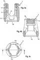
- a polyaxial bone anchoring devicecomprises a bone anchoring element 1 in the form of a bone screw having a threaded shaft 2 and a head 3.
- the head 3typically has a spherically-shaped outer surface portion 3a and a recess 3b at its free end for engagement with a tool, e.g. a driver.
- the head 3is held in a receiving part 4 that couples the bone anchoring element 1 to a stabilization rod 100.
- a sleeve-like insert piece 5providing a seat for the head 3 and a pressure member 6 for exerting pressure onto the head 3 of the bone anchoring element 1 are arranged.
- a fixation element in the form of a fixation screw 7is provided for securing and fixing the rod 100 in the receiving part 4.
- a bone anchoring device without the sleeve-like insert piece 5is also possible. In that case, the seat for the head 3 is provided at the receiving part 4 directly.
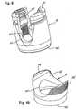
- the receiving part 4has a top end 4a and a bottom end 4b, a central axis C and a coaxial bore 41 extending from the top end 4a in the direction of the bottom end 4b.
- Adjacent to the top end 4a an U-shaped recess 42is provided that forms a channel for receiving the rod 100.
- two free legsare formed, which are provided with an internal thread 43 cooperating with the outer thread of the fixation screw 7 in an assembled state (see Fig. 2 ).
- the coaxial bore 41opens into an accommodation space 8 provided in the lower part of the receiving part 4.
- the accommodation space 8has a lower opening 45 at the bottom end 4b of the receiving part 4.
- the accommodation space 8further comprises a seat portion 46 near the bottom end 4b of the receiving part 4, in which the sleeve-like insert piece 5 is seated.
- the seat portion 46has a spherical shape in order to provide a socket for a ball and socket joint that is formed by the sleeve-insert piece 5 and the receiving part 4. It should be noted that the seat portion 46 can also be tapered or can have another shape that can be used to realize a ball and a socket joint.
- the inner diameter of the lower opening 45is smaller than the inner diameter of the accommodation space 8. It shall be noted that the inner diameter of the coaxial bore 41 does not need to be constant between the top end 4a and the accommodation space 8. It may have different portions with different diameters.
- two opposed recesses 47a, 47bare provided in the inner wall of the coaxial bore 41 and the accommodation space 8.
- the recesses 47a, 47bare aligned with the U-shaped recess 42. They extend from the bottom of the U-shaped recess 42 into the accommodation space 8.
- the size of the recesses 47a, 47bis such that the sleeve-like insert piece 5 can be introduced from the top end in a 90° tilted position, i.e. the width of the recesses 47a, 47b is greater than the height of the sleeve-like insert piece 5 in its axial direction.
- the recesses 47a, 47bextend into the accommodation space 8 to such an extent, that tilting of the sleeve-like insert piece 5 into the seat 46 is possible.
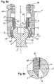
- the pressure member 6is shown in particular in Figs. 5a to 5e .
- the pressure member 6is substantially cylindrical with an outer diameter that allows the pressure member 6 to be moved within the coaxial bore 41 and the accommodation space 8, e.g. by means of a tool.
- an outer diameter of the pressure member 6is slightly larger than an inner diameter of the coaxial bore 41 to achieve an interference fit. or press fit connection between the inner surface of the coaxial bore 41 and the outer surface 65 of the pressure member 6. It is also possible that only parts of the mentioned surfaces form the interference fit.
- the pressure member 6has an upper end 6a and a lower edge 6b.
- the pressure member 6Adjacent its lower edge 6b, the pressure member 6 comprises a recess 61 with a spherical shape that matches the shape of the outer spherical surface portion 3a of the head 3. At the upper end 6a, the pressure member 6 comprises a cylindrical recess 63 for receiving the rod 100 therein. Furthermore, the pressure member 6 has a coaxial bore 64 for allowing access to the screw head 3 with a tool in an assembled state. By the coaxial bore 64 and the cylindrical recess 63 two legs are formed facing the top end 4a. The coaxial bore 64 is also configured to allow a portion of the head 3 to extend therethrough, when the bone anchoring element is in a pivoted condition.
- the sleeve-like insert piece 5is shown in particular in Figs. 6a-6d .
- the sleeve-like insert piece 5comprises an upper edge 5a and a lower edge 5b. Between the upper edge 5a and the lower edge 5b, the sleeve-like insert piece 5 comprises a spherical-shaped outer surface portion 51.
- the largest outer diameter of the sleeve-like insert piece 5is greater than the inner diameter of the lower opening 45 of the receiving part 4. Hence, the sleeve-like insert piece 5 can not escape through the lower opening 45, when it is seated in the receiving part 4.
- the dimension of the outer spherical surface portion 51corresponds to the spherical-shaped seat portion 46 of the receiving part 4 in such a way that the sleeve-like insert piece 5 can pivot and rotate in the receiving part 4, when it is seated in the seat portion 46.
- the sleeve-like insert piece 5rests in the seat portion 46 such that its centre axis 5c is coaxial with the centre axis C of the receiving part 4, the lower edge 5b projects out of the lower opening 45.
- the sleeve-like insert piece 5is pivoted in the receiving part 4, at least a portion of the lower edge 5b still projects out of the lower opening 45.
- the sleeve-like insert piece 5is hollow and comprises a central inner portion 52 that is spherically-shaped with a radius corresponding to the radius of the spherically-shaped outer surface portion 3a of the head 3 of the bone anchoring element 1.
- the lower end of the central portion 52forms a shoulder 53.
- the inner diameter of the shoulder 53is smaller than the largest outer diameter of the spherical head 3 so that the head 3 can rotate and pivot in the central spherical portion 52 of the sleeve-like insert piece 5 similar to a ball and socket joint.
- a tapered portion 54is provided that tapers outwards to allow angulation of the bone anchoring element 1 until the shaft 2 comes into contact with the lower edge 5b.
- a tapered portion 55is provided, which tapers outwards.
- the inner diameter of the tapered portion 55 and of the transition between the tapered portion 55 and the spherical central portion 52is always greater than the largest outer diameter of the head 3, so that the head 3 can be inserted from the upper edge 5a into the sleeve-like insert piece 5.
- a chamfered portion 56is provided that may serve as a stop for the pressure member 6.
- the center points of the spherical central portion 52 and the outer spherical portion 51may be offset in such a way that the centre point of the inner central spherical portion 52 is shifted in the direction towards the bottom end 4b.
- the range of angulation for the bone anchoring element 1can be further increased.
- the height of the sleeve-like insert piece 5 in axial directionis less than the height of the head 3 in axial direction such that, when the head 3 is inserted into the sleeve-like insert piece 5, still a portion of the spherical outer surface 3a of the head 3 projects from the upper edge 5a of the sleeve-like insert piece 5 as can be seen from Fig. 3a .
- the sleeve-like insert piece 5 and the anchoring element 1are independently pivotable when the shaft 2 of the anchoring element 1 and the lower edge 5b of the sleeve-like insert piece 5 are out of contact.
- the shaft 2 of the bone anchoring element 1is pivoted and engages the lower edge 5b of the sleeve-like insert piece 5, further pivoting of the bone anchoring element 1 causes the sleeve-like insert piece 5 to pivot together with the bone anchoring element 1.
- the pressure member 6is in contact with the head 3, there is a gap between the pressure member 6 and the sleeve-like insert piece 5.
- a force Fwhich is provided from above in the figures divides in frictional resistance and preload force (indicated by the small arrows in Fig. 3b ) which holds the head with respect to the receiving part 4 in a desired angular orientation by friction.
- the frictional resistanceresults from the interference fit connection between the pressure member 6 and the receiving part 4, wherein the outer diameter of at least one portion of the pressure member 6 is slightly larger than the inner diameter of the corresponding portion of the receiving part 4.
- the preload force acting on the head 4leads to a small elastic preload of the whole system.
- the steps of pre-assembling the bone anchoring device according to the first embodimentare shown with respect to Figs. 7 a) to 7 h) .
- the bone anchoring device according to the first embodimentmay be pre-assembled in such a way that first the sleeve-like insert piece 5 is tilted by 90° and inserted into the receiving part 4 at the position of the U-shaped recess 42 as can be seen from Figs. 7a and 7b . As shown in Fig. 7b the sleeve-like insert piece 5 is moved downwards into the accommodation space 8.
- the sleeve-like insert piece 5Since the outer diameter of the sleeve-like insert piece 5 is larger than the inner diameter the lower opening 45 of the receiving part 4, the sleeve-like insert piece 5 can not escape through the lower edge of the lower opening 45. Then, as shown in Figs. 7c and 7d the sleeve-like insert piece 5 is tilted so that it finally is seated in the seat portion 46, as shown in Fig. 7d .
- the bone anchoring element 1is inserted from the top end 4a of the receiving part 4 until the outer surface portion 3a of the head 3 engages the seat portion 52 of the sleeve-like insert piece 5 as can be seen from Figs. 7e and 7f .
- the pressure member 6is inserted from the top end 4a as can be seen from Fig. 7g by applying a predefined force from the top as indicated by the arrow in Fig. 7h .
- the pressure member 6is arranged in an aligned position, in which the cylindrical recess 63 is aligned with the U-shaped recess 42 of the receiving part 4 for receiving the rod 100.
- Dependent on the degree of the interference fit connectionit may be necessary to use a tool for pushing down the pressure member 6 into the receiving part 4.
- the predefined force from abovemay be generated manually or by a tool, for example and may be constant and/or force- or path-controlled.
- the bone anchoring deviceas a whole or in parts is made of a bio-compatible material, such as a bio-compatible metal, for example titanium, stainless steel, bio-compatible alloy, such as nitinol, or of bio-compatible plastic material, such as, for example, polyetheretherketone (PEEK).
- a bio-compatible materialsuch as a bio-compatible metal, for example titanium, stainless steel, bio-compatible alloy, such as nitinol, or of bio-compatible plastic material, such as, for example, polyetheretherketone (PEEK).
- Figs. 8a to 10show a second embodiment of the bone anchoring device. Parts and portions, which are the same or similar to those of the first embodiment, are designated with the same reference numerals and the description thereof is not repeated.
- the bone anchoring device according to the second embodimentdiffers from the bone anchoring device of the first embodiment by the construction of the outer surface 65' of the pressure member 6' and the corresponding surface of the coaxial bore 41' of the receiving part 4'. All other parts are identical to those of the first embodiment.
- the surface of the coaxial bore 41'is structured, for example roughened or fluted or grooved or ridged.
- the outer surface of the pressure member 6'is also structured, such as roughened or fluted or grooved or ridged.
- the surface interaction of the two structured surfacesprevents the pressure member 6' from moving backwards towards the first end 4a'. Therefore, the holding function of the interference fit connection is further increased. It is also possible that only one of the surfaces is structured.
- Figs. 11a to 13show a third embodiment of the bone anchoring device. Parts and portions, which are the same or similar to those of the first embodiment, are designated with same reference numerals and the description thereof is not repeated.
- the bone anchoring device according to the third embodimentdiffers from the bone anchoring device of the first embodiment by the construction of the pressure member 6" and the corresponding portions of the receiving part 4". All other parts are identical to those of the first embodiment.
- an interference fitis in this case only present at the lower portion 65b" of the outer surface of the pressure member 6", which contacts the surface of the coaxial bore 41" of the receiving part 4". That means, only the diameter of the lower portion 65b" is slightly larger than the diameter of the coaxial bore 41".
- the diameter of the upper portion 65a"may be the same or smaller than the diameter of the coaxial bore 41".
- the upper portion 65a"further comprises two projections 67" at the free ends of the legs of the pressure member 6", wherein the projections 67" extend radially outwards and which latch into an annular groove 48", which is provided in the coaxial bore 41" of the receiving part 4", when the pressure member 6" is inserted into the receiving part 4". Due to the larger outer diameter of the projections 67" with respect to the diameter of the coaxial bore 41" the legs of the pressure member 6" are compressed towards each other and elastically expand when the projections 67" snap into the groove 48".
- the pre-assembling of the bone anchoring device according to the second and third embodimentcorresponds to the pre-assembling according to the first embodiment.
- Fig. 14shows a fourth embodiment of the bone anchoring device, which is not according to the invention. Parts and portions, which are the same or similar to those of the first embodiment, are designated with same reference numerals and the description thereof is not repeated.
- the bone anchoring device according to the fourth embodimentdiffers from the bone anchoring device according to the first embodiment in that there is no interference fit connection between the receiving part 4"' and the pressure member 6"', i.e. the outer diameter of at least one portion of the pressure member 6"' is equal to or smaller than the inner diameter of the corresponding portion of the receiving part 4"'.
- a set screw 9"'is provided which is screwed into a through bore 49"' which is located in one leg of the receiving part 4"' during assembly for fixing the pressure member 6"' relative to the receiving part 4"'.
- the set screw 9"'comprises an engagement portion 92'" for engagement with a tool and a flat bottom side 91"' cooperating with the outer surface 65"' of the pressure member 6"'. All other parts are identical to those of the first embodiment.
- the first steps of pre-assembling the bone anchoring device according to the fourth embodimentcorrespond to the pre-assembling according to the first embodiment.
- a predefined forceis applied on the pressure member 6"' from above to define the preload force acting on the head 3"'.
- the pressure member 6"'is frictionally fixed by screwing in the set screw 9"'.
- the set screw 9"'only acts radially, i.e. perpendicular to the axis C"', onto the outer surface 65"' of the pressure member 6"' by which the pressure member 6"" is held in place. Therefore, the preload force acing on the head 3"" is maintained.
- Fig. 15shows a fifth embodiment of the bone anchoring device, which is also not according to the invention. Parts and portions, which are the same or similar to those of the first embodiment, are designated with same reference numerals and the description thereof is not repeated.
- the bone anchoring device according to the fifth embodimentdiffers from the bone anchoring device according to the first embodiment in that there is no interference fit connection between the receiving part 4"" and the pressure member 6"", i.e. the outer diameter of at least one portion of the pressure member 6"" is equal to or smaller than the inner diameter of the corresponding portion of the receiving part 4"".
- a crimping blind hole 10""is provided which is located in one leg of the receiving part 4"". All other parts are identical to those of the first embodiment.
- the first steps of pre-assembling the bone anchoring device according to the fifth embodimentcorrespond to the pre-assembling according to the first embodiment.
- a predefined forceis applied on the pressure member 6"" from above to define the preload force acting on the head 3"".
- the pressure member 6""is frictionally fixed by crimping by means of a crimping tool.
- a deformable portion 10a"" of the receiving part 4"" adjacent to the crimping blind hole 10""is deformed and deformed material radially exerts a pressure force onto the outer surface 65"" of the pressure member 6"" by which the pressure member 6"" is held in place. Therefore, the preload force acting on the head 3"" is maintained.
- bone anchoring elementall kinds of anchoring elements can be used and combined with the receiving part.
- These bone anchoring elementsare e.g. screws of different lengths, with different diameters, cannulated screws, screws with different thread forms, nails, hooks, etc.
- the head and the shaftmay also be separate parts, that are connectable to each other.
- Modifications of the receiving partinclude a recess for the rod, which is inclined or open to the side, instead of the U-shaped recess, which is perpendicular to the central axis.
- Other kinds of locking devicesincluding outer nuts, outer caps, bayonet locking devices or others are also possible.
- the inner surface portion of the pressure member that contacts the headneed not necessarily to be spherical-shaped. It can have another shape that is suitable to exert pressure onto the head.
- the pressure memberis prevented from rotation by additional crimping.
- the pressure member 6"may comprise two projections 67" extending radially outwards which are formed such that the projections 67" latch into an annular groove 48" which is provided in the bore 41", when the pressure member 6" is inserted into the receiving part 4".
- the pressure member 6, 6', 6", 6"', 6""has an upper end 6a, 6a', 6a", 6a"', 6a”” and a lower edge 6b, 6b', 6b", 6b"', 6b"", 6"', 6"" and wherein adjacent to the lower edge 6b, 6b', 6b", 6b"', 6b"", the pressure member 6, 6', 6", 6"', 6"" comprises a recess 61, 61', 61", 61"', 61"” with a spherical shape that matches the shape of an outer spherical surface portion 3a, 3a', 3a", 3a"', 3a"" of the head 3, 3', 3", 3"', 3"".
- a sleeve-like insert piece 5, 5', 5", 5"', 5""is provided encompassing a portion of the head 3, 3', 3", 3"', 3"" having an outer spherical surface portion 51, 51', 51", 51"', 51”” and being configured to pivot in the receiving part 4, 4', 4", 4"', 4"" and wherein a lower edge 5b, 5b', 5b", 5b"', 5b”" of the sleeve-like insert piece 5, 5', 5", 5"', 5"" extends through the lower opening 45, 45', 45", 45"', 45"", when the sleeve-like insert piece 5, 5', 5", 5"', 5"" is seated in the receiving part 4, 4', 4", 4"', 4"" in a position, in which its sleeveve
- the radially acting forceresults from an interference fit connection between the pressure member 6, 6', 6" and the receiving part 4, 4', 4".
- the radially acting forceresults from screwing in a set screw 9"' into a through bore 49"' in the receiving part 4"' exerting pressure onto the pressure member 6"'.
- the radially acting forceresults from crimping, wherein deformable material of the receiving part 4"" exerts pressure onto the pressure member 6".
Landscapes
- Health & Medical Sciences (AREA)
- Orthopedic Medicine & Surgery (AREA)
- Neurology (AREA)
- Life Sciences & Earth Sciences (AREA)
- Surgery (AREA)
- Heart & Thoracic Surgery (AREA)
- Engineering & Computer Science (AREA)
- Biomedical Technology (AREA)
- Nuclear Medicine, Radiotherapy & Molecular Imaging (AREA)
- Medical Informatics (AREA)
- Molecular Biology (AREA)
- Animal Behavior & Ethology (AREA)
- General Health & Medical Sciences (AREA)
- Public Health (AREA)
- Veterinary Medicine (AREA)
- Surgical Instruments (AREA)
Description
- The invention relates to a bone anchoring device comprising a bone anchoring element having a head and a shaft for anchoring in the bone, a receiving part for coupling the bone anchoring element to a rod, the receiving part comprising an accommodation space for accommodating the head and a bore being in communication with the accommodation space, the bore having a bore axis, a pressure member configured to move in the bore and comprising a first surface for engaging the head and a second surface on which the rod acts, wherein the pressure member is configured to assume a first position in which it exerts a preload onto the head that results from friction between the first surface and the head to enable the shaft to be maintained in a desired angular position before locking the head in the receiving part, and a second position in which the head is locked with respect to the receiving part, and wherein the first position is obtained by moving the pressure member by the action of a predefined force acting onto the pressure member in an axial direction and wherein the pressure member is maintained in the first position by interaction with the receiving part and can be released from the first position through action of an axial force.
US 2007/0118123 A1 describes a polyaxial bone anchor with increased angulation. The 20 polyaxial bone anchor has a locking element shaped and configured to allow an anchoring member e.g. a screw or hook to polyaxially rotate at large angles about a central axis of the bone anchor before compression locking the anchoring member within an anchor head.US 7,604,656 B2 describes an apparatus comprising a fastener, a housing having a passage, and a spacer received in the passage and engageable with the fastener, wherein pin members retain the spacer and the fastener in the housing and wherein an end portion of the pin members has a tapered surface by which the spacer is urged axially toward the fastener when the pin member is inserted through the housing. The pin members also apply an axial force to the spacer to prevent relative movement between the spacer and the housing when the rod is disengaged from the spacer and the spacer engages the fastener. The pin members hold the spacer in frictional engagement with the fastener.- Although the polyaxial bone anchoring device described above ensures an enlarged angulation in a desired orientation, there is still a need for an improved polyaxial bone anchoring device in terms of simplicity of the design and handling of the device.
EP 2 371 311 A1claim 1 and shows a receiving part with a bore and projections formed therein which respectively frictionally engage notches of a pressure element inserted into the bore, wherein a preload is exerted onto the spherical head of anchoring element. The projections are formed by crimping.US 2010/191293 A1 describes a medical implant assembly that includes a polyaxial bone anchor having a shank with an upper portion, a receiver, a retainer for holding the shank upper portion in the receiver, a lower compression insert with surfaces for closely receiving an elongate connecting member and a closure structure that may independently engage the lower compression insert to lock the shank with respect to the receiver while selectively not locking the elongate member. The walls of the receiver may be crimped at a location with respect to the lower compression insert that causes the insert to bias against and frictionally engage a domed a surface of the shank to provide a sub-assembly in which the shank is pivotable with respect to the receiver, but in a non-floppy manner at the desired articulation with respect to the shank and have the assembly hold such desired position prior to insertion of the rod.- It is the object of the invention to provide an improved polyaxial bone anchoring device.
- The object is solved by a polyaxial bone anchoring device according to
claim 1 and by a method for assembling a polyaxial bone anchoring device according toclaim 7. Further developments are given in the dependent claims. - With the polyaxial bone anchoring device a temporary clamping of the head with an exactly predetermined force in a desired angular position with respect to the receiving part without locking the head can be achieved. In this condition, the pressure member exerts a preload force onto the head in which the head is not locked but prevented from freely pivoting by friction. The preload is achieved by applying an axial force on the pressure member. The preload is then maintained by a radial force which acts on the pressure member and frictionally holds the pressure member in position with respect to the receiving part. When the head is temporarily clamped, the alignment of the receiving part with respect to the rod and the insertion of the rod is facilitated, in particular in a situation in which a multitude of bone anchors have to be connected to the rod.
- The mechanism to frictionally maintain the position of the head before locking is free from any spring members or portions. The polyaxial bone anchoring device has few parts, which are of simple design. According to an embodiment, for achieving the preload onto the head no further parts are required due to the interference fit connection. Referring to the interference fit connection the radial forces, i.e. in a 90° angle to the longitudinal axis of the receiving part, result from the elastic deformation of the material. The bone anchoring device can be manufactured easily and cost-effectively to. Furthermore, existing receiving parts can be used without having to redesign their shape. Only the pressure members have to be adapted in that an interference fit between an outer diameter of the pressure member and an inner diameter of the receiving part is achieved.
- The amount of preload exerted onto the head by the pressure member can be exactly predefined in a simple manner during assembly by adjusting the externally applied axial force. The preload onto the head generated in this way is reproducible.. The polyaxial bone anchoring device is provided to the surgeon in a pre-assembled manner, in which the pressure member is axially and rotationally fixed by friction in the receiving part to such an extent that it can not fall out or be rotated out of its aligned position. This allows a safe handling by the surgeon. Furthermore, by mounting the pressure member by means of a tool with a predetermined force, a repeatable friction fit, e.g. interference fit connection is achieved.
- According to an embodiment of the present invention, the polyaxial bone anchoring device provides for an enlarged pivot angulation of the bone screw by attaching a sleeve-like insert while equally providing high efficiency of fixation. The pivot angle of the bone anchoring element relative to the receiving part maybe equal to or greater than 45° measured from the straight position. This renders the bone anchoring device particularly suitable for the application of lateral mass fixation for example in the cervical spine. The locking mechanism for locking the bone anchoring element and the sleeve-like insert piece provides a high clamping force on a small surface. Therefore, the locking mechanism is efficient.
- The bone anchoring device can be designed as a top-loading device, wherein the bone anchoring element is inserted from the top or a bottom loading device, wherein the bone anchoring element is inserted from the bottom.
- Further features and advantages of the invention will become apparent from the description of embodiments by means of the accompanying drawings.
- In the drawings:
- Fig. 1
- shows a perspective exploded view of a polyaxial bone anchoring device with a spinal rod according to a first embodiment.
- Fig. 2
- shows a perspective view of the bone anchoring device of
Fig. 1 in an assembled state. - Fig. 3a
- shows a cross-sectional front view of the bone anchoring device of
Fig. 1 and 2 in the assembled state without the rod and without a fixation screw. - Fig. 3b
- shows an enlarged portion of the cross-sectional front view of the bone anchoring device according to
Fig. 3a . - Fig. 4a
- shows a cross-sectional front view of a receiving part according to a first embodiment.
- Fig. 4b
- shows a cross-sectional side view of the receiving part according to the first embodiment.
- Fig. 4c
- shows a top view of the receiving part according to the first embodiment.
- Fig. 4d
- shows a perspective top view of the receiving part according to the first embodiment.
- Fig. 4e
- shows a perspective bottom view of the receiving part according to the first embodiment.
- Fig. 5a
- shows a cross-sectional front view of a pressure member according to a first embodiment.
- Fig. 5b
- shows a side view of the pressure member according to the first embodiment.
- Fig. 5c
- shows a cross-sectional top view of the pressure member according to the first embodiment.
- Fig. 5d
- shows a perspective bottom view of the pressure member according to the first embodiment.
- Fig. 5e
- shows a perspective top view of the pressure member according to the first embodiment.
- Fig. 6a
- shows a cross-sectional front view of a sleeve-like insert.
- Fig. 6b
- shows a perspective top view of the sleeve-like insert.
- Fig. 6c
- shows a top view of the sleeve-like insert.
- Fig. 6d
- shows a perspective bottom view of the sleeve-like insert.
- Figs. 7a to 7h
- show steps of assembling the sleeve-like insert, the receiving part, the bone anchoring element and the pressure member.
- Fig. 8a
- shows a cross-sectional view perpendicular to the rod channel axis of a bone anchoring device in an assembled state without rod and fixation screw according to a second embodiment.
- Fig. 8b
- shows an enlarged portion of the cross-sectional view of the bone anchoring device according to
Fig. 8a . - Fig. 9
- shows a perspective view of a receiving part according to a second embodiment.
- Fig. 10
- shows a perspective view of a pressure member according to a second embodiment.
- Fig. 11a
- shows a cross-sectional view perpendicular to the rod channel axis of a bone anchoring device in an assembled state without rod and fixation screw according to a third embodiment.
- Fig. 11b
- shows an enlarged portion of the cross-sectional view of the bone anchoring device according to
Fig. 10a . - Fig. 12
- shows a perspective view of a receiving part according to a third embodiment.
- Fig. 13
- shows a perspective view of a pressure member according to a third embodiment.
- Fig. 14
- shows a cross-sectional view perpendicular to the rod channel axis of a bone anchoring device in an assembled state without rod and fixation screw according to a fourth embodiment.
- Fig. 15
- shows a cross-sectional view perpendicular to the rod channel axis of a bone anchoring device in an assembled state without rod and fixation screw according to a fifth embodiment.
- As shown in
Figs. 1 to 3b , a polyaxial bone anchoring device according to a first embodiment comprises abone anchoring element 1 in the form of a bone screw having a threadedshaft 2 and ahead 3. Thehead 3 typically has a spherically-shapedouter surface portion 3a and arecess 3b at its free end for engagement with a tool, e.g. a driver. Thehead 3 is held in a receivingpart 4 that couples thebone anchoring element 1 to astabilization rod 100. In an assembled state, in the receivingpart 4, a sleeve-like insert piece 5 providing a seat for thehead 3 and apressure member 6 for exerting pressure onto thehead 3 of thebone anchoring element 1 are arranged. Furthermore, a fixation element in the form of afixation screw 7 is provided for securing and fixing therod 100 in the receivingpart 4. A bone anchoring device without the sleeve-like insert piece 5 is also possible. In that case, the seat for thehead 3 is provided at the receivingpart 4 directly. - As can be seen from
Figs. 1 to 4c the receivingpart 4 has atop end 4a and abottom end 4b, a central axis C and acoaxial bore 41 extending from thetop end 4a in the direction of thebottom end 4b. Adjacent to thetop end 4a anU-shaped recess 42 is provided that forms a channel for receiving therod 100. By means of theU-shaped recess 42, two free legs are formed, which are provided with aninternal thread 43 cooperating with the outer thread of thefixation screw 7 in an assembled state (seeFig. 2 ). - The
coaxial bore 41 opens into anaccommodation space 8 provided in the lower part of the receivingpart 4. Theaccommodation space 8 has alower opening 45 at thebottom end 4b of the receivingpart 4. Theaccommodation space 8 further comprises aseat portion 46 near thebottom end 4b of the receivingpart 4, in which the sleeve-like insert piece 5 is seated. Theseat portion 46 has a spherical shape in order to provide a socket for a ball and socket joint that is formed by the sleeve-insert piece 5 and the receivingpart 4. It should be noted that theseat portion 46 can also be tapered or can have another shape that can be used to realize a ball and a socket joint. The inner diameter of thelower opening 45 is smaller than the inner diameter of theaccommodation space 8. It shall be noted that the inner diameter of thecoaxial bore 41 does not need to be constant between thetop end 4a and theaccommodation space 8. It may have different portions with different diameters. - In order to allow the sleeve-
like insert piece 5 to be introduced from thetop end 4a, twoopposed recesses Fig. 4c ) are provided in the inner wall of thecoaxial bore 41 and theaccommodation space 8. Therecesses U-shaped recess 42. They extend from the bottom of theU-shaped recess 42 into theaccommodation space 8. The size of therecesses like insert piece 5 can be introduced from the top end in a 90° tilted position, i.e. the width of therecesses like insert piece 5 in its axial direction. Therecesses accommodation space 8 to such an extent, that tilting of the sleeve-like insert piece 5 into theseat 46 is possible. - The
pressure member 6 is shown in particular inFigs. 5a to 5e . Thepressure member 6 is substantially cylindrical with an outer diameter that allows thepressure member 6 to be moved within thecoaxial bore 41 and theaccommodation space 8, e.g. by means of a tool. However, an outer diameter of thepressure member 6 is slightly larger than an inner diameter of thecoaxial bore 41 to achieve an interference fit. or press fit connection between the inner surface of thecoaxial bore 41 and theouter surface 65 of thepressure member 6. It is also possible that only parts of the mentioned surfaces form the interference fit. Thepressure member 6 has anupper end 6a and alower edge 6b. Adjacent itslower edge 6b, thepressure member 6 comprises arecess 61 with a spherical shape that matches the shape of the outerspherical surface portion 3a of thehead 3. At theupper end 6a, thepressure member 6 comprises acylindrical recess 63 for receiving therod 100 therein. Furthermore, thepressure member 6 has acoaxial bore 64 for allowing access to thescrew head 3 with a tool in an assembled state. By thecoaxial bore 64 and thecylindrical recess 63 two legs are formed facing thetop end 4a. Thecoaxial bore 64 is also configured to allow a portion of thehead 3 to extend therethrough, when the bone anchoring element is in a pivoted condition. - The sleeve-
like insert piece 5 is shown in particular inFigs. 6a-6d . The sleeve-like insert piece 5 comprises anupper edge 5a and alower edge 5b. Between theupper edge 5a and thelower edge 5b, the sleeve-like insert piece 5 comprises a spherical-shapedouter surface portion 51. The largest outer diameter of the sleeve-like insert piece 5 is greater than the inner diameter of thelower opening 45 of the receivingpart 4. Hence, the sleeve-like insert piece 5 can not escape through thelower opening 45, when it is seated in the receivingpart 4. The dimension of the outerspherical surface portion 51 corresponds to the spherical-shapedseat portion 46 of the receivingpart 4 in such a way that the sleeve-like insert piece 5 can pivot and rotate in the receivingpart 4, when it is seated in theseat portion 46. When the sleeve-like insert piece 5 rests in theseat portion 46 such that itscentre axis 5c is coaxial with the centre axis C of the receivingpart 4, thelower edge 5b projects out of thelower opening 45. When the sleeve-like insert piece 5 is pivoted in the receivingpart 4, at least a portion of thelower edge 5b still projects out of thelower opening 45. - The sleeve-
like insert piece 5 is hollow and comprises a centralinner portion 52 that is spherically-shaped with a radius corresponding to the radius of the spherically-shapedouter surface portion 3a of thehead 3 of thebone anchoring element 1. The lower end of thecentral portion 52 forms ashoulder 53. The inner diameter of theshoulder 53 is smaller than the largest outer diameter of thespherical head 3 so that thehead 3 can rotate and pivot in the centralspherical portion 52 of the sleeve-like insert piece 5 similar to a ball and socket joint. Between theshoulder 53 and thelower edge 5b a taperedportion 54 is provided that tapers outwards to allow angulation of thebone anchoring element 1 until theshaft 2 comes into contact with thelower edge 5b. Between the sphericalcentral portion 52 and theupper edge 5a a taperedportion 55 is provided, which tapers outwards. The inner diameter of the taperedportion 55 and of the transition between the taperedportion 55 and the sphericalcentral portion 52 is always greater than the largest outer diameter of thehead 3, so that thehead 3 can be inserted from theupper edge 5a into the sleeve-like insert piece 5. At theupper edge 5a, a chamferedportion 56 is provided that may serve as a stop for thepressure member 6. - The center points of the spherical
central portion 52 and the outerspherical portion 51 may be offset in such a way that the centre point of the inner centralspherical portion 52 is shifted in the direction towards thebottom end 4b. By means of this, the range of angulation for thebone anchoring element 1 can be further increased. The height of the sleeve-like insert piece 5 in axial direction is less than the height of thehead 3 in axial direction such that, when thehead 3 is inserted into the sleeve-like insert piece 5, still a portion of the sphericalouter surface 3a of thehead 3 projects from theupper edge 5a of the sleeve-like insert piece 5 as can be seen fromFig. 3a . - The sleeve-
like insert piece 5 and theanchoring element 1 are independently pivotable when theshaft 2 of theanchoring element 1 and thelower edge 5b of the sleeve-like insert piece 5 are out of contact. When theshaft 2 of thebone anchoring element 1 is pivoted and engages thelower edge 5b of the sleeve-like insert piece 5, further pivoting of thebone anchoring element 1 causes the sleeve-like insert piece 5 to pivot together with thebone anchoring element 1. When thepressure member 6 is in contact with thehead 3, there is a gap between thepressure member 6 and the sleeve-like insert piece 5. - As indicated by arrows in
Figs. 3a, 3b a force F which is provided from above in the figures divides in frictional resistance and preload force (indicated by the small arrows inFig. 3b ) which holds the head with respect to the receivingpart 4 in a desired angular orientation by friction. The frictional resistance results from the interference fit connection between thepressure member 6 and the receivingpart 4, wherein the outer diameter of at least one portion of thepressure member 6 is slightly larger than the inner diameter of the corresponding portion of the receivingpart 4. The preload force acting on thehead 4 leads to a small elastic preload of the whole system. - The steps of pre-assembling the bone anchoring device according to the first embodiment are shown with respect to
Figs. 7 a) to 7 h) . The bone anchoring device according to the first embodiment may be pre-assembled in such a way that first the sleeve-like insert piece 5 is tilted by 90° and inserted into the receivingpart 4 at the position of theU-shaped recess 42 as can be seen fromFigs. 7a and 7b . As shown inFig. 7b the sleeve-like insert piece 5 is moved downwards into theaccommodation space 8. Since the outer diameter of the sleeve-like insert piece 5 is larger than the inner diameter thelower opening 45 of the receivingpart 4, the sleeve-like insert piece 5 can not escape through the lower edge of thelower opening 45. Then, as shown inFigs. 7c and 7d the sleeve-like insert piece 5 is tilted so that it finally is seated in theseat portion 46, as shown inFig. 7d . - Thereafter, the
bone anchoring element 1 is inserted from thetop end 4a of the receivingpart 4 until theouter surface portion 3a of thehead 3 engages theseat portion 52 of the sleeve-like insert piece 5 as can be seen fromFigs. 7e and 7f . Then, thepressure member 6 is inserted from thetop end 4a as can be seen fromFig. 7g by applying a predefined force from the top as indicated by the arrow inFig. 7h . Thepressure member 6 is arranged in an aligned position, in which thecylindrical recess 63 is aligned with theU-shaped recess 42 of the receivingpart 4 for receiving therod 100. Dependent on the degree of the interference fit connection it may be necessary to use a tool for pushing down thepressure member 6 into the receivingpart 4. The predefined force from above may be generated manually or by a tool, for example and may be constant and/or force- or path-controlled. - The bone anchoring device as a whole or in parts is made of a bio-compatible material, such as a bio-compatible metal, for example titanium, stainless steel, bio-compatible alloy, such as nitinol, or of bio-compatible plastic material, such as, for example, polyetheretherketone (PEEK).
Figs. 8a to 10 show a second embodiment of the bone anchoring device. Parts and portions, which are the same or similar to those of the first embodiment, are designated with the same reference numerals and the description thereof is not repeated. The bone anchoring device according to the second embodiment differs from the bone anchoring device of the first embodiment by the construction of the outer surface 65' of the pressure member 6' and the corresponding surface of the coaxial bore 41' of the receiving part 4'. All other parts are identical to those of the first embodiment.- As can be seen especially from
Fig. 8b , the surface of the coaxial bore 41' is structured, for example roughened or fluted or grooved or ridged. The outer surface of the pressure member 6' is also structured, such as roughened or fluted or grooved or ridged. The surface interaction of the two structured surfaces prevents the pressure member 6' from moving backwards towards thefirst end 4a'. Therefore, the holding function of the interference fit connection is further increased. It is also possible that only one of the surfaces is structured. Figs. 11a to 13 show a third embodiment of the bone anchoring device. Parts and portions, which are the same or similar to those of the first embodiment, are designated with same reference numerals and the description thereof is not repeated. The bone anchoring device according to the third embodiment differs from the bone anchoring device of the first embodiment by the construction of thepressure member 6" and the corresponding portions of the receivingpart 4". All other parts are identical to those of the first embodiment.- Referring to the
outer surface 65" of thepressure member 6" having anupper portion 65a" and alower portion 65b" with slightly different outer diameters, an interference fit is in this case only present at thelower portion 65b" of the outer surface of thepressure member 6", which contacts the surface of thecoaxial bore 41" of the receivingpart 4". That means, only the diameter of thelower portion 65b" is slightly larger than the diameter of thecoaxial bore 41". The diameter of theupper portion 65a" may be the same or smaller than the diameter of thecoaxial bore 41". Theupper portion 65a" further comprises twoprojections 67" at the free ends of the legs of thepressure member 6", wherein theprojections 67" extend radially outwards and which latch into anannular groove 48", which is provided in thecoaxial bore 41" of the receivingpart 4", when thepressure member 6" is inserted into the receivingpart 4". Due to the larger outer diameter of theprojections 67" with respect to the diameter of thecoaxial bore 41" the legs of thepressure member 6" are compressed towards each other and elastically expand when theprojections 67" snap into thegroove 48". - The pre-assembling of the bone anchoring device according to the second and third embodiment corresponds to the pre-assembling according to the first embodiment.
Fig. 14 shows a fourth embodiment of the bone anchoring device, which is not according to the invention. Parts and portions, which are the same or similar to those of the first embodiment, are designated with same reference numerals and the description thereof is not repeated. The bone anchoring device according to the fourth embodiment differs from the bone anchoring device according to the first embodiment in that there is no interference fit connection between the receivingpart 4"' and thepressure member 6"', i.e. the outer diameter of at least one portion of thepressure member 6"' is equal to or smaller than the inner diameter of the corresponding portion of the receivingpart 4"'. Instead, a set screw 9"' is provided which is screwed into a through bore 49"' which is located in one leg of the receivingpart 4"' during assembly for fixing thepressure member 6"' relative to the receivingpart 4"'. The set screw 9"' comprises an engagement portion 92'" for engagement with a tool and a flatbottom side 91"' cooperating with theouter surface 65"' of thepressure member 6"'. All other parts are identical to those of the first embodiment.- The first steps of pre-assembling the bone anchoring device according to the fourth embodiment correspond to the pre-assembling according to the first embodiment. A predefined force is applied on the
pressure member 6"' from above to define the preload force acting on thehead 3"'. After that thepressure member 6"' is frictionally fixed by screwing in the set screw 9"'. The set screw 9"' only acts radially, i.e. perpendicular to the axis C"', onto theouter surface 65"' of thepressure member 6"' by which thepressure member 6"" is held in place. Therefore, the preload force acing on thehead 3"" is maintained. Fig. 15 shows a fifth embodiment of the bone anchoring device, which is also not according to the invention. Parts and portions, which are the same or similar to those of the first embodiment, are designated with same reference numerals and the description thereof is not repeated. The bone anchoring device according to the fifth embodiment differs from the bone anchoring device according to the first embodiment in that there is no interference fit connection between the receivingpart 4"" and thepressure member 6"", i.e. the outer diameter of at least one portion of thepressure member 6"" is equal to or smaller than the inner diameter of the corresponding portion of the receivingpart 4"". A crimping blind hole 10"" is provided which is located in one leg of the receivingpart 4"". All other parts are identical to those of the first embodiment.- The first steps of pre-assembling the bone anchoring device according to the fifth embodiment correspond to the pre-assembling according to the first embodiment. A predefined force is applied on the
pressure member 6"" from above to define the preload force acting on thehead 3"". After that, thepressure member 6"" is frictionally fixed by crimping by means of a crimping tool. Hereby adeformable portion 10a"" of the receivingpart 4"" adjacent to the crimping blind hole 10"" is deformed and deformed material radially exerts a pressure force onto theouter surface 65"" of thepressure member 6"" by which thepressure member 6"" is held in place. Therefore, the preload force acting on thehead 3"" is maintained. - Further modifications of the embodiments described are conceivable. For example, for the bone anchoring element, all kinds of anchoring elements can be used and combined with the receiving part. These bone anchoring elements are e.g. screws of different lengths, with different diameters, cannulated screws, screws with different thread forms, nails, hooks, etc. The head and the shaft may also be separate parts, that are connectable to each other.
- Modifications of the receiving part include a recess for the rod, which is inclined or open to the side, instead of the U-shaped recess, which is perpendicular to the central axis. Other kinds of locking devices including outer nuts, outer caps, bayonet locking devices or others are also possible. In all embodiments, the inner surface portion of the pressure member that contacts the head, need not necessarily to be spherical-shaped. It can have another shape that is suitable to exert pressure onto the head.
- It is also possible to use a two-part locking device for separately fixing the rod and the head of the bone anchoring element.
- It is also possible that the pressure member is prevented from rotation by additional crimping.
- It may be noted that according to specific embodiments of the polyaxial bone anchoring device, the
pressure member 6" may comprise twoprojections 67" extending radially outwards which are formed such that theprojections 67" latch into anannular groove 48" which is provided in thebore 41", when thepressure member 6" is inserted into the receivingpart 4". - According to other specific embodiments of the polyaxial bone anchoring device, which may be combined with the preceding embodiment, the
pressure member upper end lower edge lower edge pressure member recess spherical surface portion head - According to other specific embodiments of the polyaxial bone anchoring device, which may be combined with one or both the preceding embodiments, a sleeve-like insert piece 5, 5', 5", 5"', 5"" is provided encompassing a portion of the head 3, 3', 3", 3"', 3"" having an outer spherical surface portion 51, 51', 51", 51"', 51"" and being configured to pivot in the receiving part 4, 4', 4", 4"', 4"" and wherein a lower edge 5b, 5b', 5b", 5b"', 5b"" of the sleeve-like insert piece 5, 5', 5", 5"', 5"" extends through the lower opening 45, 45', 45", 45"', 45"", when the sleeve-like insert piece 5, 5', 5", 5"', 5"" is seated in the receiving part 4, 4', 4", 4"', 4"" in a position, in which its sleeve axis 5c, 5c', 5c", 5c"', 5c"" is coaxial with the longitudinal axis C.
- It may further be noted that in embodiments of the method according to the invention, the radially acting force results from an interference fit connection between the
pressure member part - According to another specific embodiments of the method, that may also be combined with the preceding embodiment, the radially acting force results from screwing in a set screw 9"' into a through bore 49"' in the receiving
part 4"' exerting pressure onto thepressure member 6"'. - According to still another specific embodiments of the method, that may be combined with one or both of the preceding embodiments, the radially acting force results from crimping, wherein deformable material of the receiving
part 4"" exerts pressure onto thepressure member 6".
Claims (9)
- A polyaxial bone anchoring device comprising
a bone anchoring element (1, 1', 1") having a head (3, 3', 3") and a shaft (2, 2', 2") for anchoring in the bone,
a receiving part (4, 4', 4") for coupling the bone anchoring element (1, 1', 1") to a rod (100), the receiving part (4, 4', 4") comprising an accommodation space (8, 8', 8") for accommodating the head (3, 3', 3") and a coaxial bore (41, 41', 41") being in communication with the accommodation space (8, 8', 8"), the coaxial bore (41, 41', 41") having a bore axis,
a pressure member (6, 6', 6") configured to move in the bore (41, 41', 41") and comprising a first surface for engaging the head (3, 3', 3") and a second surface on which the rod (100) acts, wherein
the pressure member (6, 6', 6") is configured to assume a first position in which it exerts a preload onto the head (3, 3', 3") that results from friction between the first surface and the head (3, 3', 3") to enable the shaft (2, 2', 2") to be maintained in a desired angular position before locking the head (3, 3', 3") in the receiving part (4, 4', 4"), and
a second position in which the head (3, 3', 3") is locked with respect to the receiving part (4, 4', 4"), and wherein
the first position is obtained by moving the pressure member (6, 6', 6") by the action of a predefined force acting onto the pressure member (6, 6', 6") in an axial direction and wherein
the pressure member (6, 6', 6") is maintained in the first position by interaction with the receiving part (4, 4', 4") and can be released from the first position through action of an axial force,
characterized in that the pressure member (6, 6', 6") is a single piece substantially cylindrical member and an outer diameter of the pressure member (6, 6', 6") is slightly larger than an inner diameter of the coaxial bore (41, 41', 41") to achieve an interference fit connection between an inner surface of the coaxial bore and the outer cylindrical surface (65, 65', 65b") of the pressure member, or between parts of the inner surface of the coaxial bore and of the outer cylindrical surface of the pressure member. - The polyaxial bone anchoring device of claim 1, wherein the pressure element is maintained in the first position by action of a radial force that generates friction between the pressure member (6, 6', 6") and at least a portion of the receiving part (4, 4', 4").
- The bone anchoring device of one of the claims 1 to 2, wherein the surface of the bore (41') is structured in at least a portion thereof.
- The bone anchoring device of claim 3, wherein the surface of the bore (41') is roughened, fluted, grooved or ridged in at least a portion thereof.
- The bone anchoring device of one of the claims 1 to 4, wherein the outer surface (65') of the pressure member (6') is structured in at least a portion thereof.
- The bone anchoring device of claim 5, wherein the outer surface (65') of the pressure member (6') is roughened, fluted, grooved or ridged in at least a portion thereof.
- The bone anchoring device of one of claims 3 to 6, wherein the structured surface of the bore (41') and the structured outer surface (65') of the pressure member (6') is respectively structured such as to prevent the pressure member (6') from moving backwards towards a first top end (4a') of the receiving part (4').
- The bone anchoring device of one of the claims 3 to 7, wherein the structured portion of the outer surface (65') extends partially circumferentially around a portion of the pressure member.
- A method for manufacturing a bone anchoring device according to one of the claims 1 to 8, including the steps:arranging the head (3, 3', 3") of the bone anchoring element (1, 1', 1") in the receiving part (4, 4', 4"),arranging the pressure member (6, 6', 6") in the receiving part (4, 4', 4")applying a predetermined axial force onto the pressure member (6, 6', 6") to create a preload force acting on the head (3, 3', 3") of the bone anchoring element (1, 1', 1"), wherein the preload force is maintained by a radially acting force.
Priority Applications (1)
| Application Number | Priority Date | Filing Date | Title |
|---|---|---|---|
| EP14192707.9AEP2837347B1 (en) | 2012-01-30 | 2012-01-30 | Bone anchoring device |
Applications Claiming Priority (2)
| Application Number | Priority Date | Filing Date | Title |
|---|---|---|---|
| EP14192707.9AEP2837347B1 (en) | 2012-01-30 | 2012-01-30 | Bone anchoring device |
| EP12153154.5AEP2620112B1 (en) | 2012-01-30 | 2012-01-30 | Bone anchoring device |
Related Parent Applications (1)
| Application Number | Title | Priority Date | Filing Date |
|---|---|---|---|
| EP12153154.5ADivisionEP2620112B1 (en) | 2012-01-30 | 2012-01-30 | Bone anchoring device |
Publications (3)
| Publication Number | Publication Date |
|---|---|
| EP2837347A2 EP2837347A2 (en) | 2015-02-18 |
| EP2837347A3 EP2837347A3 (en) | 2015-04-22 |
| EP2837347B1true EP2837347B1 (en) | 2018-10-03 |
Family
ID=45557933
Family Applications (2)
| Application Number | Title | Priority Date | Filing Date |
|---|---|---|---|
| EP14192707.9AActiveEP2837347B1 (en) | 2012-01-30 | 2012-01-30 | Bone anchoring device |
| EP12153154.5AActiveEP2620112B1 (en) | 2012-01-30 | 2012-01-30 | Bone anchoring device |
Family Applications After (1)
| Application Number | Title | Priority Date | Filing Date |
|---|---|---|---|
| EP12153154.5AActiveEP2620112B1 (en) | 2012-01-30 | 2012-01-30 | Bone anchoring device |
Country Status (7)
| Country | Link |
|---|---|
| US (7) | US9078705B2 (en) |
| EP (2) | EP2837347B1 (en) |
| JP (1) | JP2013154172A (en) |
| KR (1) | KR20130088083A (en) |
| CN (1) | CN103222890B (en) |
| ES (1) | ES2528969T3 (en) |
| TW (1) | TW201345480A (en) |
Families Citing this family (70)
| Publication number | Priority date | Publication date | Assignee | Title |
|---|---|---|---|---|
| US6716214B1 (en) | 2003-06-18 | 2004-04-06 | Roger P. Jackson | Polyaxial bone screw with spline capture connection |
| US7766915B2 (en) | 2004-02-27 | 2010-08-03 | Jackson Roger P | Dynamic fixation assemblies with inner core and outer coil-like member |
| JP2007525274A (en)* | 2004-02-27 | 2007-09-06 | ロジャー・ピー・ジャクソン | Orthopedic implant rod reduction instrument set and method |
| US9980753B2 (en)* | 2009-06-15 | 2018-05-29 | Roger P Jackson | pivotal anchor with snap-in-place insert having rotation blocking extensions |
| US8444681B2 (en) | 2009-06-15 | 2013-05-21 | Roger P. Jackson | Polyaxial bone anchor with pop-on shank, friction fit retainer and winged insert |
| US8979904B2 (en) | 2007-05-01 | 2015-03-17 | Roger P Jackson | Connecting member with tensioned cord, low profile rigid sleeve and spacer with torsion control |
| AU2010260521C1 (en)* | 2008-08-01 | 2013-08-01 | Roger P. Jackson | Longitudinal connecting member with sleeved tensioned cords |
| US11229457B2 (en) | 2009-06-15 | 2022-01-25 | Roger P. Jackson | Pivotal bone anchor assembly with insert tool deployment |
| US12383311B2 (en) | 2010-05-14 | 2025-08-12 | Roger P. Jackson | Pivotal bone anchor assembly and method for use thereof |
| US9345519B1 (en)* | 2010-07-02 | 2016-05-24 | Presidio Surgical, Inc. | Pedicle screw |
| JP5865479B2 (en)* | 2011-03-24 | 2016-02-17 | ロジャー・ピー・ジャクソン | Multiaxial bone anchor with compound joint and pop-mounted shank |
| US9993269B2 (en)* | 2011-07-15 | 2018-06-12 | Globus Medical, Inc. | Orthopedic fixation devices and methods of installation thereof |
| EP2559389B1 (en)* | 2011-08-18 | 2013-04-03 | Biedermann Technologies GmbH & Co. KG | Polyaxial bone anchoring device |
| EP2606841B1 (en)* | 2011-12-23 | 2016-03-09 | Biedermann Technologies GmbH & Co. KG | Polyaxial bone anchoring device |
| US8911479B2 (en) | 2012-01-10 | 2014-12-16 | Roger P. Jackson | Multi-start closures for open implants |
| US10363140B2 (en) | 2012-03-09 | 2019-07-30 | Si-Bone Inc. | Systems, device, and methods for joint fusion |
| EP3818947B1 (en) | 2012-05-04 | 2023-08-30 | SI-Bone, Inc. | Fenestrated implant |
| EP2687171B1 (en) | 2012-07-18 | 2015-04-22 | Biedermann Technologies GmbH & Co. KG | Polyaxial bone anchoring device |
| EP2764840B1 (en)* | 2013-02-11 | 2017-05-03 | Biedermann Technologies GmbH & Co. KG | Coupling assembly for coupling a rod to a bone anchoring element and bone anchoring device with such a coupling assembly |
| WO2014145902A1 (en) | 2013-03-15 | 2014-09-18 | Si-Bone Inc. | Implants for spinal fixation or fusion |
| US11147688B2 (en) | 2013-10-15 | 2021-10-19 | Si-Bone Inc. | Implant placement |
| EP2886073B1 (en) | 2013-12-19 | 2017-05-31 | Biedermann Technologies GmbH & Co. KG | Polyaxial bone anchoring device with enlarged pivot angle |
| US9498255B2 (en)* | 2013-12-31 | 2016-11-22 | Blackstone Medical, Inc. | Translational pedicle screw systems |
| US10064658B2 (en) | 2014-06-04 | 2018-09-04 | Roger P. Jackson | Polyaxial bone anchor with insert guides |
| EP2985001B1 (en) | 2014-08-11 | 2017-04-19 | Biedermann Technologies GmbH & Co. KG | Polyaxial bone anchoring device |
| JP6542362B2 (en) | 2014-09-18 | 2019-07-10 | エスアイ−ボーン・インコーポレイテッドSi−Bone, Inc. | Matrix implant |
| US10166033B2 (en) | 2014-09-18 | 2019-01-01 | Si-Bone Inc. | Implants for bone fixation or fusion |
| US10543021B2 (en)* | 2014-10-21 | 2020-01-28 | Roger P. Jackson | Pivotal bone anchor assembly having an open ring positioner for a retainer |
| US11219471B2 (en) | 2014-10-21 | 2022-01-11 | Roger P. Jackson | Pivotal bone anchor receiver having an insert with post-placement tool deployment |
| EP3031415B1 (en) | 2014-12-10 | 2018-10-31 | Biedermann Technologies GmbH & Co. KG | Coupling assembly and polyaxial bone anchoring device comprising the same |
| US9707013B2 (en)* | 2015-04-30 | 2017-07-18 | Warsaw Orthopedic, Inc. | Spinal implant system and methods of use |
| CN104783886B (en)* | 2015-05-06 | 2017-09-19 | 山东威高骨科材料股份有限公司 | Undercut mark screw base and the assembly method for positioning pressure ring |
| CN104825221B (en)* | 2015-05-14 | 2018-01-16 | 林健泽 | A kind of Improvement type pedicle screw |
| JP2017038870A (en)* | 2015-08-21 | 2017-02-23 | 京セラメディカル株式会社 | Spinal implant |
| ITUB20156292A1 (en)* | 2015-12-03 | 2017-06-03 | Medacta Int Sa | CONNECTION ELEMENT BETWEEN BARS IN A SPINOSY RECONSTRUCTION SYSTEM |
| EP3184063B1 (en)* | 2015-12-21 | 2019-07-10 | Biedermann Technologies GmbH & Co. KG | Polyaxial bone anchoring device |
| US20170290608A1 (en)* | 2016-01-22 | 2017-10-12 | Spinal Usa, Inc. | Spinal fixation systems and methods |
| CN108697445B (en) | 2016-02-26 | 2022-04-19 | 美多斯国际有限公司 | Polyaxial bone fixation element |
| US10363073B2 (en) | 2016-07-13 | 2019-07-30 | Medos International Sàrl | Bone anchor assemblies and related instrumentation |
| US10463402B2 (en) | 2016-07-13 | 2019-11-05 | Medos International Sàrl | Bone anchor assemblies and related instrumentation |
| US10874438B2 (en) | 2016-07-13 | 2020-12-29 | Medos International Sarl | Bone anchor assemblies and related instrumentation |
| US10568667B2 (en) | 2016-07-13 | 2020-02-25 | Medos International Sàrl | Bone anchor assemblies and related instrumentation |
| US11026730B2 (en) | 2017-05-10 | 2021-06-08 | Medos International Sarl | Bone anchors with drag features and related methods |
| US10610265B1 (en) | 2017-07-31 | 2020-04-07 | K2M, Inc. | Polyaxial bone screw with increased angulation |
| US11116519B2 (en) | 2017-09-26 | 2021-09-14 | Si-Bone Inc. | Systems and methods for decorticating the sacroiliac joint |
| US10966762B2 (en) | 2017-12-15 | 2021-04-06 | Medos International Sarl | Unilateral implant holders and related methods |
| ES3011907T3 (en) | 2018-03-28 | 2025-04-08 | Si Bone Inc | Threaded implants for use across bone segments |
| KR102132188B1 (en)* | 2018-04-25 | 2020-07-09 | 주식회사 멘티스로지텍 | Pedicle screw assembly capable of largely forming an angle at which a pedicle screw is bent |
| US11596449B2 (en) | 2018-09-13 | 2023-03-07 | Roger P. Jackson | Pivotal bone anchor assembly with modular receiver and universal shank head |
| WO2020102787A1 (en) | 2018-11-16 | 2020-05-22 | Surber, James L. | Pivotal bone anchor assembly having a deployable collet insert with internal pressure ring |
| EP4613244A2 (en) | 2019-02-14 | 2025-09-10 | SI-Bone Inc. | Implants for spinal fixation and or fusion |
| USD1004774S1 (en) | 2019-03-21 | 2023-11-14 | Medos International Sarl | Kerrison rod reducer |
| US11291481B2 (en) | 2019-03-21 | 2022-04-05 | Medos International Sarl | Rod reducers and related methods |
| US11291482B2 (en) | 2019-03-21 | 2022-04-05 | Medos International Sarl | Rod reducers and related methods |
| US11219470B2 (en) | 2019-07-30 | 2022-01-11 | Spine Wave, Inc. | Modular tensioned spinal screw |
| JP7646654B2 (en) | 2019-11-21 | 2025-03-17 | エスアイ-ボーン・インコーポレイテッド | Rod coupling assembly for bone stabilization construct - Patent application |
| AU2020392121B2 (en) | 2019-11-27 | 2025-05-22 | Si-Bone, Inc. | Bone stabilizing implants and methods of placement across SI joints |
| EP4072452A4 (en) | 2019-12-09 | 2023-12-20 | SI-Bone, Inc. | Sacro-iliac joint stabilizing implants and methods of implantation |
| WO2021127251A1 (en)* | 2019-12-17 | 2021-06-24 | Jackson Roger P | Bone anchor assembly with closed ring retainer and internal snap ring |
| WO2021263088A1 (en) | 2020-06-26 | 2021-12-30 | K2M, Inc. | Modular head assembly |
| EP4240262B1 (en) | 2020-11-09 | 2024-12-04 | Medos International Sàrl | Biplanar forceps reducers |
| WO2022108875A1 (en) | 2020-11-19 | 2022-05-27 | K2M, Inc. | Modular head assembly for spinal fixation |
| EP4259015A4 (en) | 2020-12-09 | 2024-09-11 | SI-Bone, Inc. | SACROILIAC JOINT STABILIZATION IMPLANTS AND METHODS OF IMPLANTATION |
| US12364515B2 (en) | 2021-03-05 | 2025-07-22 | Medos International Sàrl | Multi-feature polyaxial screw |
| EP4111992B1 (en) | 2021-07-01 | 2024-01-31 | Biedermann Technologies GmbH & Co. KG | Bone anchoring device |
| US12121268B2 (en) | 2021-07-07 | 2024-10-22 | Globus Medical, Inc. | Modular orthopedic implants, instruments, and navigation methods |
| US11751915B2 (en) | 2021-07-09 | 2023-09-12 | Roger P. Jackson | Modular spinal fixation system with bottom-loaded universal shank heads |
| US12053209B2 (en) | 2022-01-18 | 2024-08-06 | Roger P. Jackson | Spinal fixation systems with modular receiver and ring retainer sub-assemblies for connecting with universal shank heads |
| EP4260823B1 (en)* | 2022-04-11 | 2024-10-09 | Biedermann Technologies GmbH & Co. KG | Coupling device for coupling a rod to a bone anchoring element and method of manufacturing the same |
| WO2025038769A1 (en) | 2023-08-15 | 2025-02-20 | Si-Bone Inc. | Pelvic stabilization implants, methods of use and manufacture |
Family Cites Families (38)
| Publication number | Priority date | Publication date | Assignee | Title |
|---|---|---|---|---|
| US6010503A (en)* | 1998-04-03 | 2000-01-04 | Spinal Innovations, Llc | Locking mechanism |
| US6837889B2 (en)* | 2002-03-01 | 2005-01-04 | Endius Incorporated | Apparatus for connecting a longitudinal member to a bone portion |
| US7066937B2 (en) | 2002-02-13 | 2006-06-27 | Endius Incorporated | Apparatus for connecting a longitudinal member to a bone portion |
| US6716214B1 (en)* | 2003-06-18 | 2004-04-06 | Roger P. Jackson | Polyaxial bone screw with spline capture connection |
| US8377102B2 (en)* | 2003-06-18 | 2013-02-19 | Roger P. Jackson | Polyaxial bone anchor with spline capture connection and lower pressure insert |
| US7967850B2 (en) | 2003-06-18 | 2011-06-28 | Jackson Roger P | Polyaxial bone anchor with helical capture connection, insert and dual locking assembly |
| US7087057B2 (en)* | 2003-06-27 | 2006-08-08 | Depuy Acromed, Inc. | Polyaxial bone screw |
| AU2004266737B2 (en)* | 2003-08-20 | 2010-05-13 | Warsaw Orthopedic, Inc. | Multi-axial orthopedic device and system, e.g. for spinal surgery |
| WO2005065397A2 (en)* | 2003-12-30 | 2005-07-21 | Depuy Spine Sarl | Bone anchor assemblies |
| DE102004010382B4 (en)* | 2004-03-03 | 2006-04-20 | Biedermann Motech Gmbh | Bone anchoring element for anchoring in a bone or in a vertebra and its use in a stabilizing device |
| US7857834B2 (en)* | 2004-06-14 | 2010-12-28 | Zimmer Spine, Inc. | Spinal implant fixation assembly |
| US8308782B2 (en) | 2004-11-23 | 2012-11-13 | Jackson Roger P | Bone anchors with longitudinal connecting member engaging inserts and closures for fixation and optional angulation |
| US10076361B2 (en)* | 2005-02-22 | 2018-09-18 | Roger P. Jackson | Polyaxial bone screw with spherical capture, compression and alignment and retention structures |
| EP1741396B1 (en)* | 2005-07-08 | 2009-09-23 | BIEDERMANN MOTECH GmbH | Bone anchoring device |
| WO2007041702A2 (en)* | 2005-10-04 | 2007-04-12 | Alphaspine, Inc. | Pedicle screw system with provisional locking aspects |
| US20070118117A1 (en)* | 2005-10-20 | 2007-05-24 | Ebi, L.P. | Bone fixation assembly |
| US8100946B2 (en) | 2005-11-21 | 2012-01-24 | Synthes Usa, Llc | Polyaxial bone anchors with increased angulation |
| WO2007114834A1 (en)* | 2006-04-05 | 2007-10-11 | Dong Myung Jeon | Multi-axial, double locking bone screw assembly |
| US8167910B2 (en)* | 2006-10-16 | 2012-05-01 | Innovative Delta Technology Llc | Bone screw and associated assembly and methods of use thereof |
| US10792074B2 (en) | 2007-01-22 | 2020-10-06 | Roger P. Jackson | Pivotal bone anchor assemly with twist-in-place friction fit insert |
| US8197517B1 (en)* | 2007-05-08 | 2012-06-12 | Theken Spine, Llc | Frictional polyaxial screw assembly |
| PL2170192T3 (en) | 2007-07-20 | 2011-07-29 | Synthes Gmbh | Polyaxial bone fixation element |
| US20100160980A1 (en)* | 2007-07-26 | 2010-06-24 | Biotechni America Spine Group, Inc. | Spinal fixation assembly |
| US8398683B2 (en) | 2007-10-23 | 2013-03-19 | Pioneer Surgical Technology, Inc. | Rod coupling assembly and methods for bone fixation |
| AU2010260521C1 (en)* | 2008-08-01 | 2013-08-01 | Roger P. Jackson | Longitudinal connecting member with sleeved tensioned cords |
| ES2548580T3 (en)* | 2009-02-20 | 2015-10-19 | Biedermann Technologies Gmbh & Co. Kg | Receiving part for housing a rod for coupling to a bone anchoring element and bone anchoring device that includes such receiving part |
| EP2283786B1 (en)* | 2009-08-12 | 2015-06-17 | Biedermann Technologies GmbH & Co. KG | A receiving part for receiving a rod for coupling the rod to a bone anchoring element |
| EP2286748B1 (en) | 2009-08-20 | 2014-05-28 | Biedermann Technologies GmbH & Co. KG | Bone anchoring device |
| US20110196430A1 (en)* | 2010-02-10 | 2011-08-11 | Walsh David A | Spinal fixation assembly with intermediate element |
| EP2606842B1 (en)* | 2010-03-29 | 2018-08-29 | Biedermann Technologies GmbH & Co. KG | Bone anchoring device |
| JP5599227B2 (en)* | 2010-05-25 | 2014-10-01 | 京セラメディカル株式会社 | Bone anchor unit for spinal fixation |
| US9393049B2 (en) | 2010-08-20 | 2016-07-19 | K2M, Inc. | Spinal fixation system |
| US8882817B2 (en) | 2010-08-20 | 2014-11-11 | K2M, Inc. | Spinal fixation system |
| EP3047812B1 (en)* | 2010-11-22 | 2020-01-01 | Biedermann Technologies GmbH & Co. KG | Polyaxial bone anchoring device |
| ES2461843T3 (en)* | 2010-12-23 | 2014-05-21 | Biedermann Technologies Gmbh & Co. Kg | Bone anchoring device |
| US8337530B2 (en)* | 2011-03-09 | 2012-12-25 | Zimmer Spine, Inc. | Polyaxial pedicle screw with increased angulation |
| EP2559389B1 (en)* | 2011-08-18 | 2013-04-03 | Biedermann Technologies GmbH & Co. KG | Polyaxial bone anchoring device |
| US8979898B2 (en) | 2013-02-20 | 2015-03-17 | K2M, Inc. | Iliosacral polyaxial screw |
- 2012
- 2012-01-30EPEP14192707.9Apatent/EP2837347B1/enactiveActive
- 2012-01-30EPEP12153154.5Apatent/EP2620112B1/enactiveActive
- 2012-01-30ESES12153154.5Tpatent/ES2528969T3/enactiveActive
- 2013
- 2013-01-25USUS13/750,988patent/US9078705B2/enactiveActive
- 2013-01-25CNCN201310028667.8Apatent/CN103222890B/enactiveActive
- 2013-01-25TWTW102102742Apatent/TW201345480A/enunknown
- 2013-01-25JPJP2013012030Apatent/JP2013154172A/enactivePending
- 2013-01-30KRKR1020130010686Apatent/KR20130088083A/ennot_activeCeased
- 2015
- 2015-06-12USUS14/738,537patent/US9597121B2/enactiveActive
- 2017
- 2017-02-17USUS15/436,246patent/US10335204B2/enactiveActive
- 2019
- 2019-05-20USUS16/416,594patent/US11058462B2/enactiveActive
- 2019-06-13USUS16/440,741patent/US10448976B2/enactiveActive
- 2021
- 2021-06-17USUS17/350,633patent/US12193712B2/enactiveActive
- 2024
- 2024-12-17USUS18/984,648patent/US20250186090A1/enactivePending
Non-Patent Citations (1)
| Title |
|---|
| None* |
Also Published As
| Publication number | Publication date |
|---|---|
| EP2620112A1 (en) | 2013-07-31 |
| US20250186090A1 (en) | 2025-06-12 |
| US20170224387A1 (en) | 2017-08-10 |
| US20190336175A1 (en) | 2019-11-07 |
| US9597121B2 (en) | 2017-03-21 |
| EP2620112B1 (en) | 2014-11-12 |
| EP2837347A2 (en) | 2015-02-18 |
| TW201345480A (en) | 2013-11-16 |
| US20160000470A1 (en) | 2016-01-07 |
| US20190290333A1 (en) | 2019-09-26 |
| JP2013154172A (en) | 2013-08-15 |
| US20210378716A1 (en) | 2021-12-09 |
| KR20130088083A (en) | 2013-08-07 |
| CN103222890A (en) | 2013-07-31 |
| ES2528969T3 (en) | 2015-02-13 |
| US9078705B2 (en) | 2015-07-14 |
| EP2837347A3 (en) | 2015-04-22 |
| CN103222890B (en) | 2016-12-28 |
| US12193712B2 (en) | 2025-01-14 |
| US10335204B2 (en) | 2019-07-02 |
| US10448976B2 (en) | 2019-10-22 |
| US20130197586A1 (en) | 2013-08-01 |
| US11058462B2 (en) | 2021-07-13 |
Similar Documents
| Publication | Publication Date | Title |
|---|---|---|
| EP2837347B1 (en) | Bone anchoring device | |
| EP2559390B1 (en) | Polyaxial bone anchoring device with enlarged pivot angle | |
| EP2468198B1 (en) | Bone anchoring device | |
| EP3047812B1 (en) | Polyaxial bone anchoring device | |
| US11207106B2 (en) | Polyaxial bone anchoring device | |
| EP2559391B1 (en) | Polyaxial bone anchoring system | |
| EP2468199B1 (en) | Polyaxial bone anchoring device | |
| EP2606841B1 (en) | Polyaxial bone anchoring device | |
| EP2682062B1 (en) | Polyaxial bone anchoring device | |
| EP2679179B1 (en) | Bone anchoring device | |
| EP2668920B1 (en) | Polyaxial bone anchoring device | |
| EP2668919A1 (en) | Polyaxial bone anchoring device |
Legal Events
| Date | Code | Title | Description |
|---|---|---|---|
| 17P | Request for examination filed | Effective date:20141111 | |
| AC | Divisional application: reference to earlier application | Ref document number:2620112 Country of ref document:EP Kind code of ref document:P | |
| AK | Designated contracting states | Kind code of ref document:A2 Designated state(s):AL AT BE BG CH CY CZ DE DK EE ES FI FR GB GR HR HU IE IS IT LI LT LU LV MC MK MT NL NO PL PT RO RS SE SI SK SM TR | |
| PUAI | Public reference made under article 153(3) epc to a published international application that has entered the european phase | Free format text:ORIGINAL CODE: 0009012 | |
| PUAL | Search report despatched | Free format text:ORIGINAL CODE: 0009013 | |
| AK | Designated contracting states | Kind code of ref document:A3 Designated state(s):AL AT BE BG CH CY CZ DE DK EE ES FI FR GB GR HR HU IE IS IT LI LT LU LV MC MK MT NL NO PL PT RO RS SE SI SK SM TR | |
| RIC1 | Information provided on ipc code assigned before grant | Ipc:A61B 17/70 20060101AFI20150319BHEP | |
| R17P | Request for examination filed (corrected) | Effective date:20151022 | |
| RBV | Designated contracting states (corrected) | Designated state(s):AL AT BE BG CH CY CZ DE DK EE ES FI FR GB GR HR HU IE IS IT LI LT LU LV MC MK MT NL NO PL PT RO RS SE SI SK SM TR | |
| STAA | Information on the status of an ep patent application or granted ep patent | Free format text:STATUS: EXAMINATION IS IN PROGRESS | |
| 17Q | First examination report despatched | Effective date:20170508 | |
| GRAP | Despatch of communication of intention to grant a patent | Free format text:ORIGINAL CODE: EPIDOSNIGR1 | |
| STAA | Information on the status of an ep patent application or granted ep patent | Free format text:STATUS: GRANT OF PATENT IS INTENDED | |
| INTG | Intention to grant announced | Effective date:20180418 | |
| GRAJ | Information related to disapproval of communication of intention to grant by the applicant or resumption of examination proceedings by the epo deleted | Free format text:ORIGINAL CODE: EPIDOSDIGR1 | |
| STAA | Information on the status of an ep patent application or granted ep patent | Free format text:STATUS: EXAMINATION IS IN PROGRESS | |
| GRAR | Information related to intention to grant a patent recorded | Free format text:ORIGINAL CODE: EPIDOSNIGR71 | |
| GRAS | Grant fee paid | Free format text:ORIGINAL CODE: EPIDOSNIGR3 | |
| STAA | Information on the status of an ep patent application or granted ep patent | Free format text:STATUS: GRANT OF PATENT IS INTENDED | |
| GRAA | (expected) grant | Free format text:ORIGINAL CODE: 0009210 | |
| STAA | Information on the status of an ep patent application or granted ep patent | Free format text:STATUS: THE PATENT HAS BEEN GRANTED | |
| INTC | Intention to grant announced (deleted) | ||
| AC | Divisional application: reference to earlier application | Ref document number:2620112 Country of ref document:EP Kind code of ref document:P | |
| AK | Designated contracting states | Kind code of ref document:B1 Designated state(s):AL AT BE BG CH CY CZ DE DK EE ES FI FR GB GR HR HU IE IS IT LI LT LU LV MC MK MT NL NO PL PT RO RS SE SI SK SM TR | |
| INTG | Intention to grant announced | Effective date:20180828 | |
| REG | Reference to a national code | Ref country code:GB Ref legal event code:FG4D | |
| REG | Reference to a national code | Ref country code:CH Ref legal event code:EP Ref country code:CH Ref legal event code:NV Representative=s name:NOVAGRAAF INTERNATIONAL SA, CH Ref country code:AT Ref legal event code:REF Ref document number:1047791 Country of ref document:AT Kind code of ref document:T Effective date:20181015 | |
| REG | Reference to a national code | Ref country code:DE Ref legal event code:R096 Ref document number:602012051918 Country of ref document:DE Ref country code:IE Ref legal event code:FG4D | |
| REG | Reference to a national code | Ref country code:NL Ref legal event code:MP Effective date:20181003 | |
| REG | Reference to a national code | Ref country code:LT Ref legal event code:MG4D | |
| REG | Reference to a national code | Ref country code:AT Ref legal event code:MK05 Ref document number:1047791 Country of ref document:AT Kind code of ref document:T Effective date:20181003 | |
| PG25 | Lapsed in a contracting state [announced via postgrant information from national office to epo] | Ref country code:NL Free format text:LAPSE BECAUSE OF FAILURE TO SUBMIT A TRANSLATION OF THE DESCRIPTION OR TO PAY THE FEE WITHIN THE PRESCRIBED TIME-LIMIT Effective date:20181003 | |
| PG25 | Lapsed in a contracting state [announced via postgrant information from national office to epo] | Ref country code:HR Free format text:LAPSE BECAUSE OF FAILURE TO SUBMIT A TRANSLATION OF THE DESCRIPTION OR TO PAY THE FEE WITHIN THE PRESCRIBED TIME-LIMIT Effective date:20181003 Ref country code:NO Free format text:LAPSE BECAUSE OF FAILURE TO SUBMIT A TRANSLATION OF THE DESCRIPTION OR TO PAY THE FEE WITHIN THE PRESCRIBED TIME-LIMIT Effective date:20190103 Ref country code:LT Free format text:LAPSE BECAUSE OF FAILURE TO SUBMIT A TRANSLATION OF THE DESCRIPTION OR TO PAY THE FEE WITHIN THE PRESCRIBED TIME-LIMIT Effective date:20181003 Ref country code:BG Free format text:LAPSE BECAUSE OF FAILURE TO SUBMIT A TRANSLATION OF THE DESCRIPTION OR TO PAY THE FEE WITHIN THE PRESCRIBED TIME-LIMIT Effective date:20190103 Ref country code:AT Free format text:LAPSE BECAUSE OF FAILURE TO SUBMIT A TRANSLATION OF THE DESCRIPTION OR TO PAY THE FEE WITHIN THE PRESCRIBED TIME-LIMIT Effective date:20181003 Ref country code:PL Free format text:LAPSE BECAUSE OF FAILURE TO SUBMIT A TRANSLATION OF THE DESCRIPTION OR TO PAY THE FEE WITHIN THE PRESCRIBED TIME-LIMIT Effective date:20181003 Ref country code:IS Free format text:LAPSE BECAUSE OF FAILURE TO SUBMIT A TRANSLATION OF THE DESCRIPTION OR TO PAY THE FEE WITHIN THE PRESCRIBED TIME-LIMIT Effective date:20190203 Ref country code:ES Free format text:LAPSE BECAUSE OF FAILURE TO SUBMIT A TRANSLATION OF THE DESCRIPTION OR TO PAY THE FEE WITHIN THE PRESCRIBED TIME-LIMIT Effective date:20181003 Ref country code:CZ Free format text:LAPSE BECAUSE OF FAILURE TO SUBMIT A TRANSLATION OF THE DESCRIPTION OR TO PAY THE FEE WITHIN THE PRESCRIBED TIME-LIMIT Effective date:20181003 Ref country code:FI Free format text:LAPSE BECAUSE OF FAILURE TO SUBMIT A TRANSLATION OF THE DESCRIPTION OR TO PAY THE FEE WITHIN THE PRESCRIBED TIME-LIMIT Effective date:20181003 Ref country code:LV Free format text:LAPSE BECAUSE OF FAILURE TO SUBMIT A TRANSLATION OF THE DESCRIPTION OR TO PAY THE FEE WITHIN THE PRESCRIBED TIME-LIMIT Effective date:20181003 | |
| PG25 | Lapsed in a contracting state [announced via postgrant information from national office to epo] | Ref country code:RS Free format text:LAPSE BECAUSE OF FAILURE TO SUBMIT A TRANSLATION OF THE DESCRIPTION OR TO PAY THE FEE WITHIN THE PRESCRIBED TIME-LIMIT Effective date:20181003 Ref country code:SE Free format text:LAPSE BECAUSE OF FAILURE TO SUBMIT A TRANSLATION OF THE DESCRIPTION OR TO PAY THE FEE WITHIN THE PRESCRIBED TIME-LIMIT Effective date:20181003 Ref country code:AL Free format text:LAPSE BECAUSE OF FAILURE TO SUBMIT A TRANSLATION OF THE DESCRIPTION OR TO PAY THE FEE WITHIN THE PRESCRIBED TIME-LIMIT Effective date:20181003 Ref country code:GR Free format text:LAPSE BECAUSE OF FAILURE TO SUBMIT A TRANSLATION OF THE DESCRIPTION OR TO PAY THE FEE WITHIN THE PRESCRIBED TIME-LIMIT Effective date:20190104 Ref country code:PT Free format text:LAPSE BECAUSE OF FAILURE TO SUBMIT A TRANSLATION OF THE DESCRIPTION OR TO PAY THE FEE WITHIN THE PRESCRIBED TIME-LIMIT Effective date:20190203 | |
| REG | Reference to a national code | Ref country code:DE Ref legal event code:R097 Ref document number:602012051918 Country of ref document:DE | |
| PG25 | Lapsed in a contracting state [announced via postgrant information from national office to epo] | Ref country code:DK Free format text:LAPSE BECAUSE OF FAILURE TO SUBMIT A TRANSLATION OF THE DESCRIPTION OR TO PAY THE FEE WITHIN THE PRESCRIBED TIME-LIMIT Effective date:20181003 Ref country code:IT Free format text:LAPSE BECAUSE OF FAILURE TO SUBMIT A TRANSLATION OF THE DESCRIPTION OR TO PAY THE FEE WITHIN THE PRESCRIBED TIME-LIMIT Effective date:20181003 | |
| PLBE | No opposition filed within time limit | Free format text:ORIGINAL CODE: 0009261 | |
| STAA | Information on the status of an ep patent application or granted ep patent | Free format text:STATUS: NO OPPOSITION FILED WITHIN TIME LIMIT | |
| PG25 | Lapsed in a contracting state [announced via postgrant information from national office to epo] | Ref country code:MC Free format text:LAPSE BECAUSE OF FAILURE TO SUBMIT A TRANSLATION OF THE DESCRIPTION OR TO PAY THE FEE WITHIN THE PRESCRIBED TIME-LIMIT Effective date:20181003 Ref country code:RO Free format text:LAPSE BECAUSE OF FAILURE TO SUBMIT A TRANSLATION OF THE DESCRIPTION OR TO PAY THE FEE WITHIN THE PRESCRIBED TIME-LIMIT Effective date:20181003 Ref country code:SM Free format text:LAPSE BECAUSE OF FAILURE TO SUBMIT A TRANSLATION OF THE DESCRIPTION OR TO PAY THE FEE WITHIN THE PRESCRIBED TIME-LIMIT Effective date:20181003 Ref country code:EE Free format text:LAPSE BECAUSE OF FAILURE TO SUBMIT A TRANSLATION OF THE DESCRIPTION OR TO PAY THE FEE WITHIN THE PRESCRIBED TIME-LIMIT Effective date:20181003 Ref country code:SK Free format text:LAPSE BECAUSE OF FAILURE TO SUBMIT A TRANSLATION OF THE DESCRIPTION OR TO PAY THE FEE WITHIN THE PRESCRIBED TIME-LIMIT Effective date:20181003 | |
| 26N | No opposition filed | Effective date:20190704 | |
| PG25 | Lapsed in a contracting state [announced via postgrant information from national office to epo] | Ref country code:LU Free format text:LAPSE BECAUSE OF NON-PAYMENT OF DUE FEES Effective date:20190130 | |
| REG | Reference to a national code | Ref country code:BE Ref legal event code:MM Effective date:20190131 | |
| REG | Reference to a national code | Ref country code:IE Ref legal event code:MM4A | |
| PG25 | Lapsed in a contracting state [announced via postgrant information from national office to epo] | Ref country code:SI Free format text:LAPSE BECAUSE OF FAILURE TO SUBMIT A TRANSLATION OF THE DESCRIPTION OR TO PAY THE FEE WITHIN THE PRESCRIBED TIME-LIMIT Effective date:20181003 Ref country code:FR Free format text:LAPSE BECAUSE OF NON-PAYMENT OF DUE FEES Effective date:20190131 | |
| PG25 | Lapsed in a contracting state [announced via postgrant information from national office to epo] | Ref country code:BE Free format text:LAPSE BECAUSE OF NON-PAYMENT OF DUE FEES Effective date:20190131 | |
| PG25 | Lapsed in a contracting state [announced via postgrant information from national office to epo] | Ref country code:IE Free format text:LAPSE BECAUSE OF NON-PAYMENT OF DUE FEES Effective date:20190130 | |
| PG25 | Lapsed in a contracting state [announced via postgrant information from national office to epo] | Ref country code:TR Free format text:LAPSE BECAUSE OF FAILURE TO SUBMIT A TRANSLATION OF THE DESCRIPTION OR TO PAY THE FEE WITHIN THE PRESCRIBED TIME-LIMIT Effective date:20181003 | |
| PG25 | Lapsed in a contracting state [announced via postgrant information from national office to epo] | Ref country code:MT Free format text:LAPSE BECAUSE OF NON-PAYMENT OF DUE FEES Effective date:20190130 | |
| PG25 | Lapsed in a contracting state [announced via postgrant information from national office to epo] | Ref country code:CY Free format text:LAPSE BECAUSE OF FAILURE TO SUBMIT A TRANSLATION OF THE DESCRIPTION OR TO PAY THE FEE WITHIN THE PRESCRIBED TIME-LIMIT Effective date:20181003 | |
| PG25 | Lapsed in a contracting state [announced via postgrant information from national office to epo] | Ref country code:HU Free format text:LAPSE BECAUSE OF FAILURE TO SUBMIT A TRANSLATION OF THE DESCRIPTION OR TO PAY THE FEE WITHIN THE PRESCRIBED TIME-LIMIT; INVALID AB INITIO Effective date:20120130 | |
| PG25 | Lapsed in a contracting state [announced via postgrant information from national office to epo] | Ref country code:MK Free format text:LAPSE BECAUSE OF FAILURE TO SUBMIT A TRANSLATION OF THE DESCRIPTION OR TO PAY THE FEE WITHIN THE PRESCRIBED TIME-LIMIT Effective date:20181003 | |
| P01 | Opt-out of the competence of the unified patent court (upc) registered | Effective date:20230525 | |
| PGFP | Annual fee paid to national office [announced via postgrant information from national office to epo] | Ref country code:GB Payment date:20241230 Year of fee payment:14 | |
| PGFP | Annual fee paid to national office [announced via postgrant information from national office to epo] | Ref country code:DE Payment date:20250130 Year of fee payment:14 | |
| PGFP | Annual fee paid to national office [announced via postgrant information from national office to epo] | Ref country code:CH Payment date:20250201 Year of fee payment:14 |