EP2836123B1 - Push-to-charge lancing device - Google Patents
Push-to-charge lancing deviceDownload PDFInfo
- Publication number
- EP2836123B1 EP2836123B1EP13718017.0AEP13718017AEP2836123B1EP 2836123 B1EP2836123 B1EP 2836123B1EP 13718017 AEP13718017 AEP 13718017AEP 2836123 B1EP2836123 B1EP 2836123B1
- Authority
- EP
- European Patent Office
- Prior art keywords
- lancet carrier
- drive mechanism
- lancing device
- piston
- drive
- Prior art date
- Legal status (The legal status is an assumption and is not a legal conclusion. Google has not performed a legal analysis and makes no representation as to the accuracy of the status listed.)
- Active
Links
Images


Classifications
- A—HUMAN NECESSITIES
- A61—MEDICAL OR VETERINARY SCIENCE; HYGIENE
- A61B—DIAGNOSIS; SURGERY; IDENTIFICATION
- A61B5/00—Measuring for diagnostic purposes; Identification of persons
- A61B5/15—Devices for taking samples of blood
- A61B5/151—Devices specially adapted for taking samples of capillary blood, e.g. by lancets, needles or blades
- A61B5/15101—Details
- A61B5/15115—Driving means for propelling the piercing element to pierce the skin, e.g. comprising mechanisms based on shape memory alloys, magnetism, solenoids, piezoelectric effect, biased elements, resilient elements, vacuum or compressed fluids
- A61B5/15117—Driving means for propelling the piercing element to pierce the skin, e.g. comprising mechanisms based on shape memory alloys, magnetism, solenoids, piezoelectric effect, biased elements, resilient elements, vacuum or compressed fluids comprising biased elements, resilient elements or a spring, e.g. a helical spring, leaf spring, or elastic strap
- A—HUMAN NECESSITIES
- A61—MEDICAL OR VETERINARY SCIENCE; HYGIENE
- A61B—DIAGNOSIS; SURGERY; IDENTIFICATION
- A61B5/00—Measuring for diagnostic purposes; Identification of persons
- A61B5/15—Devices for taking samples of blood
- A61B5/150007—Details
- A61B5/150015—Source of blood
- A61B5/150022—Source of blood for capillary blood or interstitial fluid
- A—HUMAN NECESSITIES
- A61—MEDICAL OR VETERINARY SCIENCE; HYGIENE
- A61B—DIAGNOSIS; SURGERY; IDENTIFICATION
- A61B5/00—Measuring for diagnostic purposes; Identification of persons
- A61B5/15—Devices for taking samples of blood
- A61B5/150007—Details
- A61B5/150374—Details of piercing elements or protective means for preventing accidental injuries by such piercing elements
- A61B5/150381—Design of piercing elements
- A61B5/150412—Pointed piercing elements, e.g. needles, lancets for piercing the skin
- A—HUMAN NECESSITIES
- A61—MEDICAL OR VETERINARY SCIENCE; HYGIENE
- A61B—DIAGNOSIS; SURGERY; IDENTIFICATION
- A61B5/00—Measuring for diagnostic purposes; Identification of persons
- A61B5/15—Devices for taking samples of blood
- A61B5/150007—Details
- A61B5/150374—Details of piercing elements or protective means for preventing accidental injuries by such piercing elements
- A61B5/150381—Design of piercing elements
- A61B5/150503—Single-ended needles
- A—HUMAN NECESSITIES
- A61—MEDICAL OR VETERINARY SCIENCE; HYGIENE
- A61B—DIAGNOSIS; SURGERY; IDENTIFICATION
- A61B5/00—Measuring for diagnostic purposes; Identification of persons
- A61B5/15—Devices for taking samples of blood
- A61B5/151—Devices specially adapted for taking samples of capillary blood, e.g. by lancets, needles or blades
- A61B5/15101—Details
- A61B5/15103—Piercing procedure
- A61B5/15107—Piercing being assisted by a triggering mechanism
- A61B5/15113—Manually triggered, i.e. the triggering requires a deliberate action by the user such as pressing a drive button
- A—HUMAN NECESSITIES
- A61—MEDICAL OR VETERINARY SCIENCE; HYGIENE
- A61B—DIAGNOSIS; SURGERY; IDENTIFICATION
- A61B5/00—Measuring for diagnostic purposes; Identification of persons
- A61B5/15—Devices for taking samples of blood
- A61B5/151—Devices specially adapted for taking samples of capillary blood, e.g. by lancets, needles or blades
- A61B5/15186—Devices loaded with a single lancet, i.e. a single lancet with or without a casing is loaded into a reusable drive device and then discarded after use; drive devices reloadable for multiple use
- A61B5/15188—Constructional features of reusable driving devices
- A61B5/1519—Constructional features of reusable driving devices comprising driving means, e.g. a spring, for propelling the piercing unit
- A—HUMAN NECESSITIES
- A61—MEDICAL OR VETERINARY SCIENCE; HYGIENE
- A61B—DIAGNOSIS; SURGERY; IDENTIFICATION
- A61B5/00—Measuring for diagnostic purposes; Identification of persons
- A61B5/15—Devices for taking samples of blood
- A61B5/151—Devices specially adapted for taking samples of capillary blood, e.g. by lancets, needles or blades
- A61B5/15186—Devices loaded with a single lancet, i.e. a single lancet with or without a casing is loaded into a reusable drive device and then discarded after use; drive devices reloadable for multiple use
- A61B5/15188—Constructional features of reusable driving devices
- A61B5/15192—Constructional features of reusable driving devices comprising driving means, e.g. a spring, for retracting the lancet unit into the driving device housing
- A61B5/15194—Constructional features of reusable driving devices comprising driving means, e.g. a spring, for retracting the lancet unit into the driving device housing fully automatically retracted, i.e. the retraction does not require a deliberate action by the user, e.g. by terminating the contact with the patient's skin
Definitions
- the present inventionrelates generally to the field of medical devices, and more particularly to a lancing device for blood sampling and testing, and an incorporated mechanism for charging the lancet drive mechanism by pushing an exposed portion of the mechanism into the lancing device.
- Lancing devicesare utilized for penetrating the skin of a human or animal subject at a lancing site to obtain a sample of blood or other body fluid for medical testing, as in blood-typing or blood-glucose testing.
- Known lancing devicescommonly include a housing containing a drive mechanism, a charging mechanism for energizing the spring or other drive means of the drive mechanism, and a release mechanism for releasing the drive mechanism upon actuation.
- U.S. Patent App. Serial No. 13/005,181(Pub. No. US 2011/0196261 )
- U.S. Patent App. Serial No. 12/641,674(Pub. No. US 2010/0160942 ) show example lancing devices.
- a lancetis typically propelled by the drive mechanism from a retracted position within the housing to an extended position wherein a sharp tip portion of the lancet projects from the housing to prick the subject's skin at a desired lancing site.
- Many known lancing devicescommonly use a drive mechanism that is charged or energized by pulling the drive mechanism to a retracted position, generally away from the body of the lancing device, resulting in the user having to perform the charging procedure by actuating or pulling the charging mechanism away from the body of the lancing device.
- EP 1219242discloses a body fluid sampler including first and second plunger rods connected via a spring, a latch mechanism and a release mechanism.
- the latch mechanismcomprises first and second engagement members supported at both ends, for restricting movement of the first and second plunger rod.
- a release mechanismis provided for releasing the latched state of the first and second plunger rod.
- WO 2010/019741discloses a lancing device comprising: a lancet; a lancet holder receiving the lancet and configured to move axially in a housing between a retracted position, an extending position and a cocked position; a cocking mechanism; and a trigger.
- the triggerhas a guide structure for slidable receipt of the cocking mechanism.
- the lancet holderis released from the cocked position to the extended position.
- DE 102010004370discloses a lancing device comprising a lancet holder that is linearly displaceable within a housing.
- an operating knobis actuated such that projections on a latching hook come into contact with projections on a trip slider, pushing it upwards and compressing a spring.
- the trip slidercomes into contact with abutments on the housing, causing the latching hooks to disengage from the lancet holder.
- the charging and release of the lancet holderare effected by a single downward actuation of the operating knob.
- WO 2010/128701discloses a lancing device comprising a lancet mounting device having an elastic body and being slidably received within a housing.
- a lancet mounting deviceTo charge the lancing device, the lancet mounting device is retracted so as to compress a compression spring and engage the elastic body behind a load button extending from the housing. To release the lancet mounting device, a trigger is actuated so as to release the elastic body from the load button.
- WO 2008/098046discloses a lancet device comprising a housing for slidably receiving a holding member and a push-button.
- the holding membercomprises a deflecting member that engages with a shoulder of the housing when the holding member is in a charged state. The user fires a trigger to move the deflecting member out of engagement with the shoulder, releasing the holding member in a forward direction.
- the present inventionprovides a lancing device having improved drive and charging features.
- a charging mechanismis provided for actuating into a lancet carrier of the lancing device for charging a drive spring.
- the drive springis partially housed within a slot of the lancet carrier wherein a piston is translatably mounted to receive a portion of the charging mechanism upon actuation, further charging the drive spring.
- a release mechanismis provided for actuating the lancet carrier. Additional example embodiments of the present invention provide improved methods of use of lancing devices.
- the present inventionrelates to a lancing device for completing a lancing stroke.
- the lancing deviceincludes a lancet carrier with a distal end and a proximal end.
- the lancing devicealso includes a drive mechanism to drive the lancet carrier through the lancing stroke.
- the lancing devicealso includes a charge mechanism to charge the drive mechanism.
- the charge mechanismis configured to apply a charging force onto the drive mechanism by pushing the charge mechanism along a common direction with the lancing stroke.
- the lancing devicealso includes a piston with a proximal end and a distal end. The piston distal end engages the drive mechanism and the piston proximal end engages the charge mechanism.
- the lancing devicealso includes at least one detent.
- the detentincludes a resiliently-flexible cantilevered arm having an attached proximal end and a distal free end.
- the cantilevered armcomprises a ramped surface at the distal free end.
- the piston proximal endreleasably engages the at least one detent when the drive mechanism is charged by the charge mechanism.
- the lancing devicemay include a housing with a proximal end and a distal end and a hollow core.
- the proximal endmay include an aperture.
- the lancet carriermay be translatably supported within the housing.
- the drive mechanismmay be supported with respect to the lancet carrier.
- the drive mechanismmay include a relaxed state and a charged state.
- the charge mechanismmay be translatably inserted through the housing proximal end aperture.
- the inventionin another aspect, relates to a method for charging a drive mechanism in a lancing device.
- the methodincludes engaging a charge mechanism with respect to a drive mechanism that is translatably supported within a lancet carrier.
- the lancet carrierincludes a proximal end and a distal end, and the drive mechanism includes a relaxed state and a charged state.
- the methodalso includes pushing the charge mechanism towards the lancet carrier distal end and releasably engaging the drive mechanism with respect to a detent on the lancing device when the drive mechanism is in the charged state.
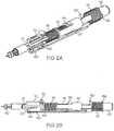
- the lancing device 10generally includes a housing 12 and an end cap 14 removably secured to the housing, for example through corresponding threaded surfaces or friction fit.
- the housing 12at least partially encloses a lancing-stroke drive mechanism that includes a drive spring 15 for driving a lancet carrier 20 along a lancing stroke, a drive piston 34 for applying an anti-bias compressive force to the drive spring and a return spring 16 for returning the lancet carrier to a neutral position.
- a charging plunger 50is provided for charging the lancing-stroke mechanism by actuating the drive piston 34 in translation against the bias of the drive spring 15.
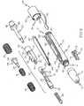
- Figure 3shows an exploded assembly view of the lancing device 10.
- the drive piston 34applies an anti-bias compressive force on the drive spring 15 along a common axial direction with the lancing stroke.
- the piston 34is traversed distally of one or more interengaging detents or catch features 36 extending within the housing 12, to hold the drive spring 15 in a charged state before entering the lancing stroke.
- the detent or catch feature 36includes a resiliently-flexible cantilevered arm having a ramped surface or shaped detent, at the distal free end, to releasably engage and retain the drive piston base 35 flange.
- the housing 12generally includes an elongate member having a front distal end 11 and a rear proximal end 13 generally opposite thereto.
- the front distal end 11includes a threaded outer surface and a longitudinally-oriented aperture 19.
- Opposing vertically-oriented apertures 62 and 76are provided near the housing front end 11 to receive the release mechanism 60, as described above, and an ejector 70 for ejecting a used lancet 40.
- the lancet carrier 20generally includes two members, a lancet-carrying member 21 and the piston-carrying member 22.
- the lancet-carrying member 21carries the lancet 40 along a lancing stroke and selectively engages the housing 12 to prevent relative movement therein.
- the lancet-carrying member 21has a distal end with a receiver cavity 24 for receiving and holding a lancet 40 throughout the lancing procedure.
- the lancet-carrying member 21includes a release finger 23 integrally formed with or attached thereon.
- the release finger 23has a cantilevered shape and includes a distal free end having a sloped surface or feature to catch or run within the interior of the housing 12.
- the lancet-carrying member 21also includes a proximal end with a receiver feature 26.
- the piston-carrying member 22has a distal end and a proximal end that includes a cylindrical body with a distal end face 31 and a proximal end face.
- the distal end of the piston-carrying member 22includes an aperture 92.
- a hollow elongated channel 27extends through the proximal cylindrical body between the distal face 31 and the proximal face.
- the distal end aperture 92is axially aligned with the hollow elongated channel 27.
- a slot chamber 32extends between the distal end of the piston-carrying member 22 and the distal face 31 of the proximal cylindrical body of the piston-carrying member.
- the slot chamber 32can have a generally circumferential geometry with opposing apertures along the length of each side.
- the overhang flange 33extends from the proximal end body of the piston-carrying member 22 over the slot chamber 32, forming a recession area underneath the overhang flange.
- the piston-carrying member 22functions to translatably support or receive the drive piston 34 within the slot chamber 32.
- the piston-carrying member 22 distal endsecures to the lancet-carrying member 21, preferably with one or more cooperating connection features.
- the lancet-carrying member receiver mechanism 26can include a pair of opposing apertures providing access to a hollow internal core 29.
- a pair of resilient probes 30 with outwardly-oriented barbscan protrude from the distal end of the piston-carrying member 22.
- the resilient probe barbs 30insert into the lancet-carrying core through the proximal end and secure through the opposing apertures 26.
- the drive piston 34has a base support 35 and a probe nose 37 extending distally away from the base support.
- the base support 35can have a generally-circumferential flange.
- the base support 35can have a hollow bore interior (not shown) for receiving the charging plunger 50.
- the drive piston 34is naturally biased by the drive spring 15 applying a force on the flange of the base support 35 towards a face surface 31 recessed under an overhang flange 33 at the proximal end of the distal slot chamber 32.
- the distal end of the piston probe nose 37slidably inserts through the aperture 92 in the distal end of the piston-carrying member 22.
- the slot chamber 32translatably receives the drive piston 34 and the drive spring 15 that is secured around the piston nose probe 37.
- the drive spring 15is retained between a front distal end of the slot chamber 32 and the piston base flange 35.
- the bias of the drive spring 15urges the base flange 35 to be positioned or nest against the recessed face surface 31 underneath the overhang flange 33.
- the piston base 35 flange and the recessed region under the overhang flange 31have a substantially similar contour.
- the charging plunger 50can extend through the elongated hollow channel and insert into the piston base bore.
- the charging plunger 50generally includes an elongated body with a button 52 and the elongated probe nose 54.
- the distal end of the elongated probe nose 54inserts into the proximal end aperture of the hollow elongated channel 27 and translatably exits the distal end aperture of the hollow elongated channel.
- an internal bore(not shown) extending from the flange on the piston base 35 can align with the distal front aperture of the elongated hollow channel 27 to receive the distal end of the elongated probe nose.
- the piston probe nose 37then inserts through distal aperture 92, so that the piston is translatably supported by the aperture 92 and the distal end 54 of the charging plunger 50.
- the charging plunger 50has a retention guide 56 that is integrally formed between the elongated probe nose 54 and the button 52 extends generally perpendicular to the axis of the elongated plunger body and comprises four radially offset arms or pedals that extend beyond the circumferential diameter of the button.
- a release mechanism or button 60is provided for removing a release finger 23 on the lancet carrier 20 from engagement with the distal end of a trigger catch 62 on the housing 12.
- the lancet carrier 20is naturally driven, by the bias of the drive spring 15 against the drive piston 34, towards an aperture 17 in the distal end of the end cap 14.
- the sharp tip of a lancet 40being carried by the driven lancet carrier 20, projects through the aperture 17 to be used on a subject's skin at a lancing site.
- the recessed region under the overhang flange 33receives the piston base 35 and the overhang flange then engages the detents or catch feature 36.
- the overhang flange 33engages the catch feature 36 and flexes the cantilevered arm free end upwardly to slide along the outer surface of the piston-receiving member 22 proximal end, as best shown in Figure 9D .
- This engagementdisengages the detents or catch features 36 from the piston base 35 flange and then upward onto the exterior surface of the proximal region of a piston-receiving member 22 of the lancet carrier 20.
- the return spring 16is compressed by an anti-bias force applied by the piston-receiving member 22.
- the return spring 16then naturally biases the lancet carrier away from the aperture towards the neutral position, as best shown in Figure 9E .
- the detent or catch feature 36With the piston base 35 within the recession under the overhang flange 33, the detent or catch feature 36 then can slide over the overhang flange to allow the lancet carrier 20 to return to the neutral state.
- the release mechanism 60has a generally elongated body with a deformably-resilient distal end region.
- the distal end regionincludes a button 64 and a fastener 66, for example a pair of resiliently-flexible outwardly-facing barbs, extending from the underside at a position proximal from the distal end.
- the proximal end of the release mechanism 60includes an insert 67 extending from the underside of the proximal end.
- the release mechanism 60is secured onto the housing 12.
- the housing catch 62can be an aperture with a narrowed proximal region 63.
- the release mechanism fastener 66snaps into the narrowed proximal region 63 of the distal aperture 62 and the proximal insert 67 fits within the proximal cutout 69.
- the distal button 64inserts through the distal catch aperture 62 and engages the sloped distal end of the cantilevered arm 23 on the lancet-carrying member 21.
- the deformably-resilient distal end of the release mechanism 60can be depressed so that the button 64 applies a downward force to the sloped distal end of the cantilevered finger 23 to disengage the cantilevered finger from the catch aperture 62.
- the housing 12also has a cutout 69 positioned at the proximal end of the housing.
- the insert 67 of the release mechanism 60can engage the proximal end face of the piston-carrying member 22 to prevent the lancet carrier 20 from being pushed in a proximal or reversed direction towards the proximal end 13 of the housing 12.
- the ejector 70generally includes a main elongate body and a handle 72 that protrudes away from the main elongate body.
- a cantilevered arm 74is generally laterally offset from, and parallel to, the elongate body and extends the length of the elongate body.
- the ejector 70preferably has a uniform construction, for example through injection molding.
- An elongated channel 94, with proximal and distal apertures,extends along the underside of the lancet-receiving member 21 between the receiver cavity 24 and a midpoint along the lancet-receiving member body.
- the channel 94receives the arm 74 and allows the arm to translatably move proximally and distally with respect to the lancet-receiving member 21.
- a distally-directed user-applied force applied to the ejector handle 72translates the arm 74 along the elongated channel 94 in the receiver cavity 25, and through the channel distal aperture, so that the arm applies a distally-oriented force against a used lancet 40 in the receiver cavity to eject the lancet from the receiver cavity.
- the end cap 14is preferably removed from the distal end 11 of the housing 12.
- a collar 80can secure around the plunger button 52.
- the collar 80generally includes a hollow circumferential interior extending between a distal open end 81 and a proximal open end with an inwardly-directed lip (not shown).
- the distal open end 81has one or more generally circumferentially-shaped detents or catching features 82 positioned to catch or engage at least one corresponding detent or catching feature 84 positioned around the proximal end 13 of the housing 12.
- the distal open end 81fits over the button 52 and the retention guide 56 arms snap over the detents or catching features 82.
- the button 52extends outwardly from the collar 80 through the proximal end 83 aperture (not shown).
- a clip or arm member 90may be integrally formed with or attached to the collar 80 for coupling the lancing device 10, for example by engaging the clip with a pocket or an article of clothing.
- a biasing spring 51is retained around the probe nose 54 on the elongated body of the charging plunger 50 between the retention guide 56 and the housing proximal end 13.
- the biasing spring 51biases the charging plunger 50 away from the housing proximal end 13.
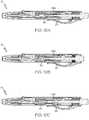
- the lancet carrier 20translates from a neutral or first position, as depicted in Figure 9A , to an advanced position, depicted in Figure 9D , and back to a neutral position shown in Figure 9E .
- the neutral position shown in Figure 9Athe release finger 23 of the lancet carrier 20 engages the trigger catch 62 of the housing 12, prohibiting the lancet carrier 20 from moving towards the distal end 11 of the housing and end cap aperture 17.
- the drive spring 15biases against the base 35 flange of the drive piston 34 towards the recessed face surface 31 underneath the overhang flange 32.
- the probe nose 54actuates forward to engage the base 35 of the drive piston 34, further actuating the base 35 distally beyond the resilient cantilevered catch feature 36 to hold the drive piston 34 in a charged state shown in Figure 9B .
- the drive spring 15is compressed against bias between the piston base 35 and the distal end of the slot chamber 32.
- the biasing spring 51biases the charging plunger 50 back to a neutral position shown in Figure 9C .
- the bias of the drive spring 15 against the base 35drives the lancet carrier 20 in a distal direction, shown in Figure 9D , into an advanced position for penetrating the subject's skin at the lancing site.
- the bias of the drive spring 15forces lancet carrier 20 in a distal direction to receive the drive piston 34 into the recessed face surface 31 under the overhang flange 33.
- the forward extent of travel of the lancet carrieris limited by contact of the lancet with the inner face around the aperture 17 of the cap 14.
- the catch featurepivotally mounts to the housing for engaging the head of the drive piston when actuated by the charging mechanism.
- a pivotal catch feature 136having a substantially similar shape as the catch feature 36, pivotally mounts to the housing near the proximal end 13.
- the operation of the pivotal catch feature 136 throughout the sequencing of the lancing device 10is generally similar to the above-described catch feature 36, and similarly retains the drive piston 34 in a charged state until a portion of the lancet carrier 20 removes the catch feature from the drive piston, as best shown in Figure 10D .
- the proximal end of the piston-carrying member 22is generally short in length to allow a portion of the pivotal catch feature 136 to pivot into the housing 12 when the flange overhang 33 removes the catch feature from the drive piston 34.
- the position of the proximal portion of the lancet carrier 20 in the first positionbiases or prohibits the pivotal catch 136 from releasing and pivoting therein, ensuring that the catch remains engaged and latched with the piston 34 until the lancet carrier is advanced.
- the pivotal catch feature 136can include one or more biasing members or springs to bias the catch feature 136 to partially extend beyond the internal surface of the housing 12.
- the system and method of example forms of the inventionenable a user to charge the drive mechanism of a lancing device by pushing or pressing an actuator portion in an advancing or forward direction to energize the drive spring, in the familiar manner of operating a retractable ball-point pen.
- the drive mechanismUpon actuation of the release mechanism, the drive mechanism propels the lancet along an advancing portion of a lancing stroke, also in the advancing or forward direction.
- the lancetis generally coaxially aligned with the actuator portion of the drive mechanism.
Landscapes
- Health & Medical Sciences (AREA)
- Life Sciences & Earth Sciences (AREA)
- Heart & Thoracic Surgery (AREA)
- Medical Informatics (AREA)
- Biophysics (AREA)
- Pathology (AREA)
- Engineering & Computer Science (AREA)
- Biomedical Technology (AREA)
- Hematology (AREA)
- Physics & Mathematics (AREA)
- Molecular Biology (AREA)
- Surgery (AREA)
- Animal Behavior & Ethology (AREA)
- General Health & Medical Sciences (AREA)
- Public Health (AREA)
- Veterinary Medicine (AREA)
- Dermatology (AREA)
- Measurement Of The Respiration, Hearing Ability, Form, And Blood Characteristics Of Living Organisms (AREA)
Description
- This application claims the priority benefit of
U.S. Provisional Patent Application Serial No. 61/621,830 filed April 9, 2012 - The present invention relates generally to the field of medical devices, and more particularly to a lancing device for blood sampling and testing, and an incorporated mechanism for charging the lancet drive mechanism by pushing an exposed portion of the mechanism into the lancing device.
- Lancing devices are utilized for penetrating the skin of a human or animal subject at a lancing site to obtain a sample of blood or other body fluid for medical testing, as in blood-typing or blood-glucose testing. Known lancing devices commonly include a housing containing a drive mechanism, a charging mechanism for energizing the spring or other drive means of the drive mechanism, and a release mechanism for releasing the drive mechanism upon actuation.
U.S. Patent App. Serial No. 13/005,181 (Pub. No.US 2011/0196261 ) andU.S. Patent App. Serial No. 12/641,674 (Pub. No.US 2010/0160942 ) show example lancing devices. - A lancet is typically propelled by the drive mechanism from a retracted position within the housing to an extended position wherein a sharp tip portion of the lancet projects from the housing to prick the subject's skin at a desired lancing site. Many known lancing devices commonly use a drive mechanism that is charged or energized by pulling the drive mechanism to a retracted position, generally away from the body of the lancing device, resulting in the user having to perform the charging procedure by actuating or pulling the charging mechanism away from the body of the lancing device. Charging the drive mechanism by pulling the charging mechanism away from the body of the lancing device can present challenges to users with reduced manual dexterity, and may require the subject or user to use two hands to hold the device body and pull the handle until the device is charged and ready to activate.
EP 1219242 discloses a body fluid sampler including first and second plunger rods connected via a spring, a latch mechanism and a release mechanism. The latch mechanism comprises first and second engagement members supported at both ends, for restricting movement of the first and second plunger rod. A release mechanism is provided for releasing the latched state of the first and second plunger rod.WO 2010/019741 discloses a lancing device comprising: a lancet; a lancet holder receiving the lancet and configured to move axially in a housing between a retracted position, an extending position and a cocked position; a cocking mechanism; and a trigger. The trigger has a guide structure for slidable receipt of the cocking mechanism. Upon actuation of the trigger, the lancet holder is released from the cocked position to the extended position.DE 102010004370 discloses a lancing device comprising a lancet holder that is linearly displaceable within a housing. In use, an operating knob is actuated such that projections on a latching hook come into contact with projections on a trip slider, pushing it upwards and compressing a spring. As the operating knob is further actuated, the trip slider comes into contact with abutments on the housing, causing the latching hooks to disengage from the lancet holder. The charging and release of the lancet holder are effected by a single downward actuation of the operating knob.WO 2010/128701 discloses a lancing device comprising a lancet mounting device having an elastic body and being slidably received within a housing. To charge the lancing device, the lancet mounting device is retracted so as to compress a compression spring and engage the elastic body behind a load button extending from the housing. To release the lancet mounting device, a trigger is actuated so as to release the elastic body from the load button.WO 2008/098046 discloses a lancet device comprising a housing for slidably receiving a holding member and a push-button. The holding member comprises a deflecting member that engages with a shoulder of the housing when the holding member is in a charged state. The user fires a trigger to move the deflecting member out of engagement with the shoulder, releasing the holding member in a forward direction. - Needs exist for improved systems and methods for charging of lancing devices. It is to the provision of improved lancing devices and methods of operation and use thereof that the present invention is primarily directed.
- In example embodiments, the present invention provides a lancing device having improved drive and charging features. A charging mechanism is provided for actuating into a lancet carrier of the lancing device for charging a drive spring. The drive spring is partially housed within a slot of the lancet carrier wherein a piston is translatably mounted to receive a portion of the charging mechanism upon actuation, further charging the drive spring. A release mechanism is provided for actuating the lancet carrier. Additional example embodiments of the present invention provide improved methods of use of lancing devices.
- In one aspect, the present invention relates to a lancing device for completing a lancing stroke. The lancing device includes a lancet carrier with a distal end and a proximal end. The lancing device also includes a drive mechanism to drive the lancet carrier through the lancing stroke. The lancing device also includes a charge mechanism to charge the drive mechanism. The charge mechanism is configured to apply a charging force onto the drive mechanism by pushing the charge mechanism along a common direction with the lancing stroke. The lancing device also includes a piston with a proximal end and a distal end. The piston distal end engages the drive mechanism and the piston proximal end engages the charge mechanism. The lancing device also includes at least one detent. The detent includes a resiliently-flexible cantilevered arm having an attached proximal end and a distal free end. The cantilevered arm comprises a ramped surface at the distal free end. The piston proximal end releasably engages the at least one detent when the drive mechanism is charged by the charge mechanism.
- The lancing device may include a housing with a proximal end and a distal end and a hollow core. The proximal end may include an aperture. The lancet carrier may be translatably supported within the housing. The drive mechanism may be supported with respect to the lancet carrier. The drive mechanism may include a relaxed state and a charged state. The charge mechanism may be translatably inserted through the housing proximal end aperture.
- In another aspect, the invention relates to a method for charging a drive mechanism in a lancing device. The method includes engaging a charge mechanism with respect to a drive mechanism that is translatably supported within a lancet carrier. The lancet carrier includes a proximal end and a distal end, and the drive mechanism includes a relaxed state and a charged state. The method also includes pushing the charge mechanism towards the lancet carrier distal end and releasably engaging the drive mechanism with respect to a detent on the lancing device when the drive mechanism is in the charged state.
- These and other aspects, features and advantages of the invention will be understood with reference to the drawing figures and detailed description herein, and will be realized by means of the various elements and combinations particularly pointed out in the appended claims. It is to be understood that both the foregoing general description and the following brief description of the drawings and detailed description of the invention are exemplary and explanatory of preferred embodiments of the invention, and are not restrictive of the invention, as claimed.
FIGURE 1A is an underneath perspective view of a lancing device according to an example embodiment of the present invention.FIGURE 1B is a top perspective view of the lancing device ofFIGURE 1A .FIGURES 2A and2B show internal views, with the housing removed and in a neutral state, of the lancing device ofFIGURES 1A and1B .FIGURE 3 is an exploded assembly view of the lancing device ofFIGURES 1A and1B .FIGURE 4A is an isolated top perspective view of the housing portion of the lancing device ofFIGURE 3 .FIGURE 4B is an isolated top perspective view of a lancet carrier portion of the lancet carrier ofFIGURE 3 .FIGURE 5 is an isolated perspective view of the piston-receiving portion of the lancet carrier ofFIGURE 4B .FIGURE 6 is an isolated perspective view of the lancet-carrier portion of the lancet carrier ofFIGURE 4B .FIGURE 7 is a front view of the lancet-carrier portion of the lancet carrier inFIGURE 6 , as viewed along line A.FIGURE 8 is a rear view of the lancet-carrier portion of the lancet carrier inFIGURE 6 , as viewed along line B.FIGURES 9A-9E are cross-sectional views of the lancing device ofFIGURES 1A and1B , showing the sequential operation moving between a neutral state, a charging state, a charged state, and a fully extended state, and returning to the neutral state.FIGURES 10A-10E are cross-sectional views of a lancing device according to another example embodiment of the invention, showing the sequential operation moving between a neutral state, a charging state, a charged state, and a fully extended state, and returning to the neutral state.- The present invention may be understood more readily by reference to the following detailed description of the invention taken in connection with the accompanying drawing figures, which form a part of this disclosure. It is to be understood that this invention is not limited to the specific devices, methods, conditions or parameters described and/or shown herein, and that the terminology used herein is for the purpose of describing particular embodiments by way of example only and is not intended to be limiting of the claimed invention.
- Also, as used in the specification including the appended claims, the singular forms "a," "an," and "the" include the plural, and reference to a particular numerical value includes at least that particular value, unless the context clearly dictates otherwise. Ranges may be expressed herein as from "about" or "approximately" one particular value and/or to "about" or "approximately" another particular value. When such a range is expressed, another embodiment includes from the one particular value and/or to the other particular value. Similarly, when values are expressed as approximations, by use of the antecedent "about," it will be understood that the particular value forms another embodiment.
- With reference now to the drawing figures, wherein like reference numbers represent corresponding parts throughout the several views,
Figures 1 - 9E show a lancingdevice 10 according to an example embodiment of the invention. The lancingdevice 10 generally includes ahousing 12 and anend cap 14 removably secured to the housing, for example through corresponding threaded surfaces or friction fit. Thehousing 12 at least partially encloses a lancing-stroke drive mechanism that includes adrive spring 15 for driving alancet carrier 20 along a lancing stroke, adrive piston 34 for applying an anti-bias compressive force to the drive spring and areturn spring 16 for returning the lancet carrier to a neutral position. A chargingplunger 50 is provided for charging the lancing-stroke mechanism by actuating thedrive piston 34 in translation against the bias of thedrive spring 15. Figure 3 shows an exploded assembly view of the lancingdevice 10. As depicted, thedrive piston 34 applies an anti-bias compressive force on thedrive spring 15 along a common axial direction with the lancing stroke. Thepiston 34 is traversed distally of one or more interengaging detents or catch features 36 extending within thehousing 12, to hold thedrive spring 15 in a charged state before entering the lancing stroke. The detent or catchfeature 36 includes a resiliently-flexible cantilevered arm having a ramped surface or shaped detent, at the distal free end, to releasably engage and retain thedrive piston base 35 flange.- The
housing 12 generally includes an elongate member having a frontdistal end 11 and a rearproximal end 13 generally opposite thereto. The frontdistal end 11 includes a threaded outer surface and a longitudinally-orientedaperture 19. Opposing vertically-orientedapertures front end 11 to receive therelease mechanism 60, as described above, and anejector 70 for ejecting a usedlancet 40. - The
lancet carrier 20 generally includes two members, a lancet-carryingmember 21 and the piston-carryingmember 22. The lancet-carryingmember 21 carries thelancet 40 along a lancing stroke and selectively engages thehousing 12 to prevent relative movement therein. The lancet-carryingmember 21 has a distal end with areceiver cavity 24 for receiving and holding alancet 40 throughout the lancing procedure. The lancet-carryingmember 21 includes arelease finger 23 integrally formed with or attached thereon. Preferably, therelease finger 23 has a cantilevered shape and includes a distal free end having a sloped surface or feature to catch or run within the interior of thehousing 12. The lancet-carryingmember 21 also includes a proximal end with areceiver feature 26. - The piston-carrying
member 22 has a distal end and a proximal end that includes a cylindrical body with adistal end face 31 and a proximal end face. The distal end of the piston-carryingmember 22 includes anaperture 92. A hollowelongated channel 27 extends through the proximal cylindrical body between thedistal face 31 and the proximal face. Thedistal end aperture 92 is axially aligned with the hollowelongated channel 27. - A
slot chamber 32 extends between the distal end of the piston-carryingmember 22 and thedistal face 31 of the proximal cylindrical body of the piston-carrying member. Theslot chamber 32 can have a generally circumferential geometry with opposing apertures along the length of each side. Theoverhang flange 33 extends from the proximal end body of the piston-carryingmember 22 over theslot chamber 32, forming a recession area underneath the overhang flange. The piston-carryingmember 22 functions to translatably support or receive thedrive piston 34 within theslot chamber 32. - The piston-carrying
member 22 distal end secures to the lancet-carryingmember 21, preferably with one or more cooperating connection features. For example, the lancet-carryingmember receiver mechanism 26 can include a pair of opposing apertures providing access to a hollowinternal core 29. A pair ofresilient probes 30 with outwardly-oriented barbs can protrude from the distal end of the piston-carryingmember 22. Theresilient probe barbs 30 insert into the lancet-carrying core through the proximal end and secure through the opposingapertures 26. - As depicted, the
drive piston 34 has abase support 35 and aprobe nose 37 extending distally away from the base support. Thebase support 35 can have a generally-circumferential flange. Optionally, thebase support 35 can have a hollow bore interior (not shown) for receiving the chargingplunger 50. Thedrive piston 34 is naturally biased by thedrive spring 15 applying a force on the flange of thebase support 35 towards aface surface 31 recessed under anoverhang flange 33 at the proximal end of thedistal slot chamber 32. The distal end of thepiston probe nose 37 slidably inserts through theaperture 92 in the distal end of the piston-carryingmember 22. - The
slot chamber 32 translatably receives thedrive piston 34 and thedrive spring 15 that is secured around thepiston nose probe 37. Thedrive spring 15 is retained between a front distal end of theslot chamber 32 and thepiston base flange 35. The bias of thedrive spring 15 urges thebase flange 35 to be positioned or nest against the recessedface surface 31 underneath theoverhang flange 33. Preferably, thepiston base 35 flange and the recessed region under theoverhang flange 31 have a substantially similar contour. - When the
piston base 35 bore and theelongated channel aperture 27 are axially aligned, the chargingplunger 50 can extend through the elongated hollow channel and insert into the piston base bore. The chargingplunger 50 generally includes an elongated body with abutton 52 and theelongated probe nose 54. The distal end of theelongated probe nose 54 inserts into the proximal end aperture of the hollowelongated channel 27 and translatably exits the distal end aperture of the hollow elongated channel. Optionally, an internal bore (not shown) extending from the flange on thepiston base 35 can align with the distal front aperture of the elongatedhollow channel 27 to receive the distal end of the elongated probe nose. Thepiston probe nose 37 then inserts throughdistal aperture 92, so that the piston is translatably supported by theaperture 92 and thedistal end 54 of the chargingplunger 50. - Application of a distally-directed force to the
button 52 by a user forces thedrive piston 34 in translation against the bias of thedrive spring 15 secured around the piston. This distally-directed translation of thepiston 34 causes thedrive spring 15 to compress between thepiston base 35 flange and the distal end face of theslot chamber 32. Thereturn spring 16 is secured around the lancet-carryingmember 21 between the front face of the piston-carryingmember 22 distal end and a combination of therelease mechanism fastener 66 and theejector arm 74, as best shown inFigures 2A & 2B . - The charging
plunger 50 has aretention guide 56 that is integrally formed between theelongated probe nose 54 and thebutton 52 extends generally perpendicular to the axis of the elongated plunger body and comprises four radially offset arms or pedals that extend beyond the circumferential diameter of the button. - A release mechanism or
button 60 is provided for removing arelease finger 23 on thelancet carrier 20 from engagement with the distal end of atrigger catch 62 on thehousing 12. When therelease finger 23 is disengaged from the distal end of thetrigger catch 62, thelancet carrier 20 is naturally driven, by the bias of thedrive spring 15 against thedrive piston 34, towards anaperture 17 in the distal end of theend cap 14. The sharp tip of alancet 40, being carried by the drivenlancet carrier 20, projects through theaperture 17 to be used on a subject's skin at a lancing site. - When the
lancet carrier 20 is driven forward by thedrive spring 15, the recessed region under theoverhang flange 33 receives thepiston base 35 and the overhang flange then engages the detents or catchfeature 36. Upon thelancet carrier 20 being driven toward the advanced position within thehousing 12 by thedrive spring 15, theoverhang flange 33 engages thecatch feature 36 and flexes the cantilevered arm free end upwardly to slide along the outer surface of the piston-receivingmember 22 proximal end, as best shown inFigure 9D . This engagement disengages the detents or catch features 36 from thepiston base 35 flange and then upward onto the exterior surface of the proximal region of a piston-receivingmember 22 of thelancet carrier 20. - As a consequence of the natural bias of the
drive spring 15, thereturn spring 16 is compressed by an anti-bias force applied by the piston-receivingmember 22. After thelancet carrier 20 is driven distally towards theend cap aperture 17, thereturn spring 16 then naturally biases the lancet carrier away from the aperture towards the neutral position, as best shown inFigure 9E . With thepiston base 35 within the recession under theoverhang flange 33, the detent or catchfeature 36 then can slide over the overhang flange to allow thelancet carrier 20 to return to the neutral state. - When the
return spring 16 pushes thedrive piston 34 to return to a neutral state within the recession underneath theoverhang flange 33, the lancet carrier returns to a first position at a position proximal to thecatch feature 36, as best shown inFigure 9E . - The
release mechanism 60 has a generally elongated body with a deformably-resilient distal end region. The distal end region includes abutton 64 and afastener 66, for example a pair of resiliently-flexible outwardly-facing barbs, extending from the underside at a position proximal from the distal end. The proximal end of therelease mechanism 60 includes aninsert 67 extending from the underside of the proximal end. - In use, the
release mechanism 60 is secured onto thehousing 12. Thehousing catch 62 can be an aperture with a narrowedproximal region 63. Therelease mechanism fastener 66 snaps into the narrowedproximal region 63 of thedistal aperture 62 and theproximal insert 67 fits within theproximal cutout 69. When therelease mechanism 60 is secured to thehousing 12, thedistal button 64 inserts through thedistal catch aperture 62 and engages the sloped distal end of the cantileveredarm 23 on the lancet-carryingmember 21. The deformably-resilient distal end of therelease mechanism 60 can be depressed so that thebutton 64 applies a downward force to the sloped distal end of the cantileveredfinger 23 to disengage the cantilevered finger from thecatch aperture 62. - The
housing 12 also has acutout 69 positioned at the proximal end of the housing. Theinsert 67 of therelease mechanism 60 can engage the proximal end face of the piston-carryingmember 22 to prevent thelancet carrier 20 from being pushed in a proximal or reversed direction towards theproximal end 13 of thehousing 12. - The
ejector 70 generally includes a main elongate body and ahandle 72 that protrudes away from the main elongate body. A cantileveredarm 74 is generally laterally offset from, and parallel to, the elongate body and extends the length of the elongate body. Theejector 70 preferably has a uniform construction, for example through injection molding. Anelongated channel 94, with proximal and distal apertures, extends along the underside of the lancet-receivingmember 21 between thereceiver cavity 24 and a midpoint along the lancet-receiving member body. Thechannel 94 receives thearm 74 and allows the arm to translatably move proximally and distally with respect to the lancet-receivingmember 21. In use, a distally-directed user-applied force applied to the ejector handle 72 translates thearm 74 along theelongated channel 94 in the receiver cavity 25, and through the channel distal aperture, so that the arm applies a distally-oriented force against a usedlancet 40 in the receiver cavity to eject the lancet from the receiver cavity. When the described ejection process is performed, theend cap 14 is preferably removed from thedistal end 11 of thehousing 12. - A
collar 80 can secure around theplunger button 52. Thecollar 80 generally includes a hollow circumferential interior extending between a distalopen end 81 and a proximal open end with an inwardly-directed lip (not shown). Preferably, the distalopen end 81 has one or more generally circumferentially-shaped detents or catchingfeatures 82 positioned to catch or engage at least one corresponding detent or catchingfeature 84 positioned around theproximal end 13 of thehousing 12. The distalopen end 81 fits over thebutton 52 and theretention guide 56 arms snap over the detents or catching features 82. Then, thebutton 52 extends outwardly from thecollar 80 through theproximal end 83 aperture (not shown). Theretention guide 56 arms engage the inner surface of theproximal end 83 lip (not shown) to prevent theplunger 50 from exiting through theproximal end 83 aperture (not shown) of the collar. Optionally, a clip orarm member 90 may be integrally formed with or attached to thecollar 80 for coupling the lancingdevice 10, for example by engaging the clip with a pocket or an article of clothing. - As best shown in
Figures 2A and2B , a biasingspring 51 is retained around theprobe nose 54 on the elongated body of the chargingplunger 50 between theretention guide 56 and the housingproximal end 13. The biasingspring 51 biases the chargingplunger 50 away from the housingproximal end 13. - In the sequence of operation, the
lancet carrier 20 translates from a neutral or first position, as depicted inFigure 9A , to an advanced position, depicted inFigure 9D , and back to a neutral position shown inFigure 9E . In the neutral position shown inFigure 9A , therelease finger 23 of thelancet carrier 20 engages thetrigger catch 62 of thehousing 12, prohibiting thelancet carrier 20 from moving towards thedistal end 11 of the housing andend cap aperture 17. Thedrive spring 15 biases against thebase 35 flange of thedrive piston 34 towards the recessedface surface 31 underneath theoverhang flange 32. When thebutton 52 of the chargingplunger 50 is pressed into the device, theprobe nose 54 actuates forward to engage thebase 35 of thedrive piston 34, further actuating thebase 35 distally beyond the resilient cantileveredcatch feature 36 to hold thedrive piston 34 in a charged state shown inFigure 9B . In the charged state, thedrive spring 15 is compressed against bias between thepiston base 35 and the distal end of theslot chamber 32. Once the drive mechanism is charged, the biasingspring 51 biases the chargingplunger 50 back to a neutral position shown inFigure 9C . - When the lancing device is fired by depression of the distal end of the
release mechanism 60, as previously described, the bias of thedrive spring 15 against the base 35 drives thelancet carrier 20 in a distal direction, shown inFigure 9D , into an advanced position for penetrating the subject's skin at the lancing site. During this lancet stroke, the bias of thedrive spring 15forces lancet carrier 20 in a distal direction to receive thedrive piston 34 into the recessedface surface 31 under theoverhang flange 33. In the depicted embodiment, the forward extent of travel of the lancet carrier is limited by contact of the lancet with the inner face around theaperture 17 of thecap 14. - Because the bias of the
drive spring 15 forces theentire lancet carrier 20 in a distal direction, theoverhang flange 33 moves to engage and outwardly-flex thecatch feature 36 onto the outer surface of the piston-carrying member proximal end body. As a consequence of this distal movement by thelancet carrier 22, thereturn spring 16 is also compressed against bias. When thedrive spring 15 has fully biased and thecatch feature 36 is slidably engaged with the outer surface of the piston-carrying member proximal body, the natural bias of thereturn spring 16 forces thelancet carrier 20 proximally back to a neutral position to complete the lancing stroke, shown inFigure 9E . - In further example embodiments, the catch feature pivotally mounts to the housing for engaging the head of the drive piston when actuated by the charging mechanism. For example, as depicted in
Figures 10A-10E , apivotal catch feature 136, having a substantially similar shape as thecatch feature 36, pivotally mounts to the housing near theproximal end 13. The operation of thepivotal catch feature 136 throughout the sequencing of the lancingdevice 10 is generally similar to the above-describedcatch feature 36, and similarly retains thedrive piston 34 in a charged state until a portion of thelancet carrier 20 removes the catch feature from the drive piston, as best shown inFigure 10D . Preferably, the proximal end of the piston-carryingmember 22 is generally short in length to allow a portion of thepivotal catch feature 136 to pivot into thehousing 12 when theflange overhang 33 removes the catch feature from thedrive piston 34. Additionally, as depicted inFigures 10B-10C , the position of the proximal portion of thelancet carrier 20 in the first position biases or prohibits thepivotal catch 136 from releasing and pivoting therein, ensuring that the catch remains engaged and latched with thepiston 34 until the lancet carrier is advanced. When thelancet carrier 20 is in a forward or extended position thepivotal catch 136 is free to rotate and release thedrive piston 34. In additional example embodiments, thepivotal catch feature 136 can include one or more biasing members or springs to bias thecatch feature 136 to partially extend beyond the internal surface of thehousing 12. - The system and method of example forms of the invention enable a user to charge the drive mechanism of a lancing device by pushing or pressing an actuator portion in an advancing or forward direction to energize the drive spring, in the familiar manner of operating a retractable ball-point pen. Upon actuation of the release mechanism, the drive mechanism propels the lancet along an advancing portion of a lancing stroke, also in the advancing or forward direction. In example embodiments, the lancet is generally coaxially aligned with the actuator portion of the drive mechanism.
- While the invention has been described with reference to preferred and example embodiments, it will be understood by those skilled in the art that a variety of modifications, additions and deletions are within the scope of the invention, as defined by the following claims.
Claims (13)
- A lancing device (10) for completing a lancing stroke, the lancing device (10) comprising:a lancet carrier (20) comprising a distal end and a proximal end;a drive mechanism (15, 16, 34) to drive the lancet carrier (20) through the lancing stroke;a charge mechanism to charge the drive mechanism (15, 16, 34), the charge mechanism configured to apply a charging force onto the drive mechanism (15, 16, 34) by pushing the charge mechanism along a common direction with the lancing stroke;a piston (34) with a proximal end and a distal end, wherein the piston distal end engages the drive mechanism (15, 16, 34) and the piston proximal end engages the charge mechanism; andat least one detent (36),characterized in that the detent (36) includes a resiliently-flexible cantilevered arm having an attached proximal end and a distal free end, wherein the cantilevered arm comprises a ramped surface at the distal free end, and wherein the piston proximal end releasably engages the at least one detent (36) when the drive mechanism (15, 16, 34) is charged by the charge mechanism.
- The lancing device (10) of Claim 1, wherein the drive mechanism (15, 16, 34) comprises a drive spring (15) that biases in an opposite direction than the lancing stroke.
- The lancing device (10) of Claim 1, wherein the piston (34) is translationally secured between the lancet carrier distal end and the lancet carrier proximal end.
- The lancing device (10) of Claim 1, wherein the lancet carrier (20) is configured to disengage with respect to the at least one detent (36) and the drive mechanism (15, 16, 34) during the lancing stroke.
- The lancing device (10) of Claim 4, wherein the lancet carrier (20) comprises an overhang flange (33) configured to disengage with respect to the at least one detent (36) and the drive mechanism (15, 16, 34).
- The lancing device (10) of Claim 1, wherein the charge mechanism comprises a plunger (50), the plunger (50) being translationally supported with respect to the lancet carrier (20).
- The lancing device (10) of claim 1, further comprising a housing (12) comprising a proximal end (13) and a distal end (11) and a hollow core, the proximal end (13) comprising an aperture;
wherein the lancet carrier (20) is translationally supported within the housing (12);
wherein the drive mechanism (15, 16, 34) is supported with respect to the lancet carrier (20), the drive mechanism (15, 16, 34) comprising a relaxed state and a charged state; and
wherein the charge mechanism is translationally inserted through the housing proximal end aperture. - The lancing device (10) of Claim 7, wherein the cantilevered arm extends from the housing (12).
- The lancing device (10) of Claim 8, wherein the lancet carrier (20) comprises a hollow body (32) extending from the lancet carrier proximal end toward the lancet carrier distal end, the lancet carrier hollow body (32) is configured to disengage the ramped surface from the drive mechanism (15, 16, 34).
- The lancing device of Claim 7, wherein the drive mechanism comprises a drive spring and the piston is translationally supported between the lancet carrier proximal end and the lancet carrier distal end, wherein the piston engages the drive spring.
- The lancing device (10) of Claim 10, wherein the drive spring (15) is compressed during the drive mechanism charged state.
- The lancing device (10) of Claim 11, wherein the drive spring (15) is biased oppositely to the charge mechanism push engagement direction.
- A method for charging a drive mechanism (15, 16, 34) in a lancing device (10) according to claim 1, the method comprising the steps of:engaging the charge mechanism with respect to the drive mechanism (15, 16, 34) that is translationally supported within the lancet carrier (20), the drive mechanism (15, 16, 34) comprising a relaxed state and a charged state;pushing the charge mechanism towards the lancet carrier distal end; andreleasably engaging the drive mechanism (15, 16, 34) with respect to the at least one detent (36) on the lancing device when the drive mechanism (15, 16, 34) is in the charged state.
Applications Claiming Priority (2)
| Application Number | Priority Date | Filing Date | Title |
|---|---|---|---|
| US201261621830P | 2012-04-09 | 2012-04-09 | |
| PCT/US2013/035746WO2013155052A1 (en) | 2012-04-09 | 2013-04-09 | Push-to-charge lancing device |
Publications (2)
| Publication Number | Publication Date |
|---|---|
| EP2836123A1 EP2836123A1 (en) | 2015-02-18 |
| EP2836123B1true EP2836123B1 (en) | 2017-05-10 |
Family
ID=48143645
Family Applications (1)
| Application Number | Title | Priority Date | Filing Date |
|---|---|---|---|
| EP13718017.0AActiveEP2836123B1 (en) | 2012-04-09 | 2013-04-09 | Push-to-charge lancing device |
Country Status (4)
| Country | Link |
|---|---|
| US (1) | US20130267978A1 (en) |
| EP (1) | EP2836123B1 (en) |
| CA (1) | CA2869338C (en) |
| WO (1) | WO2013155052A1 (en) |
Families Citing this family (397)
| Publication number | Priority date | Publication date | Assignee | Title |
|---|---|---|---|---|
| US20070084897A1 (en) | 2003-05-20 | 2007-04-19 | Shelton Frederick E Iv | Articulating surgical stapling instrument incorporating a two-piece e-beam firing mechanism |
| US9060770B2 (en) | 2003-05-20 | 2015-06-23 | Ethicon Endo-Surgery, Inc. | Robotically-driven surgical instrument with E-beam driver |
| US11890012B2 (en) | 2004-07-28 | 2024-02-06 | Cilag Gmbh International | Staple cartridge comprising cartridge body and attached support |
| US11998198B2 (en) | 2004-07-28 | 2024-06-04 | Cilag Gmbh International | Surgical stapling instrument incorporating a two-piece E-beam firing mechanism |
| US8215531B2 (en) | 2004-07-28 | 2012-07-10 | Ethicon Endo-Surgery, Inc. | Surgical stapling instrument having a medical substance dispenser |
| US9072535B2 (en) | 2011-05-27 | 2015-07-07 | Ethicon Endo-Surgery, Inc. | Surgical stapling instruments with rotatable staple deployment arrangements |
| US11246590B2 (en) | 2005-08-31 | 2022-02-15 | Cilag Gmbh International | Staple cartridge including staple drivers having different unfired heights |
| US11484312B2 (en) | 2005-08-31 | 2022-11-01 | Cilag Gmbh International | Staple cartridge comprising a staple driver arrangement |
| US7934630B2 (en) | 2005-08-31 | 2011-05-03 | Ethicon Endo-Surgery, Inc. | Staple cartridges for forming staples having differing formed staple heights |
| US10159482B2 (en) | 2005-08-31 | 2018-12-25 | Ethicon Llc | Fastener cartridge assembly comprising a fixed anvil and different staple heights |
| US7669746B2 (en) | 2005-08-31 | 2010-03-02 | Ethicon Endo-Surgery, Inc. | Staple cartridges for forming staples having differing formed staple heights |
| US9237891B2 (en) | 2005-08-31 | 2016-01-19 | Ethicon Endo-Surgery, Inc. | Robotically-controlled surgical stapling devices that produce formed staples having different lengths |
| US20070106317A1 (en) | 2005-11-09 | 2007-05-10 | Shelton Frederick E Iv | Hydraulically and electrically actuated articulation joints for surgical instruments |
| US20120292367A1 (en) | 2006-01-31 | 2012-11-22 | Ethicon Endo-Surgery, Inc. | Robotically-controlled end effector |
| US20110295295A1 (en) | 2006-01-31 | 2011-12-01 | Ethicon Endo-Surgery, Inc. | Robotically-controlled surgical instrument having recording capabilities |
| US11793518B2 (en) | 2006-01-31 | 2023-10-24 | Cilag Gmbh International | Powered surgical instruments with firing system lockout arrangements |
| US7753904B2 (en) | 2006-01-31 | 2010-07-13 | Ethicon Endo-Surgery, Inc. | Endoscopic surgical instrument with a handle that can articulate with respect to the shaft |
| US20110024477A1 (en) | 2009-02-06 | 2011-02-03 | Hall Steven G | Driven Surgical Stapler Improvements |
| US8820603B2 (en) | 2006-01-31 | 2014-09-02 | Ethicon Endo-Surgery, Inc. | Accessing data stored in a memory of a surgical instrument |
| US11224427B2 (en) | 2006-01-31 | 2022-01-18 | Cilag Gmbh International | Surgical stapling system including a console and retraction assembly |
| US8186555B2 (en) | 2006-01-31 | 2012-05-29 | Ethicon Endo-Surgery, Inc. | Motor-driven surgical cutting and fastening instrument with mechanical closure system |
| US7845537B2 (en) | 2006-01-31 | 2010-12-07 | Ethicon Endo-Surgery, Inc. | Surgical instrument having recording capabilities |
| US8708213B2 (en) | 2006-01-31 | 2014-04-29 | Ethicon Endo-Surgery, Inc. | Surgical instrument having a feedback system |
| US11278279B2 (en) | 2006-01-31 | 2022-03-22 | Cilag Gmbh International | Surgical instrument assembly |
| US8992422B2 (en) | 2006-03-23 | 2015-03-31 | Ethicon Endo-Surgery, Inc. | Robotically-controlled endoscopic accessory channel |
| US8322455B2 (en) | 2006-06-27 | 2012-12-04 | Ethicon Endo-Surgery, Inc. | Manually driven surgical cutting and fastening instrument |
| US10568652B2 (en) | 2006-09-29 | 2020-02-25 | Ethicon Llc | Surgical staples having attached drivers of different heights and stapling instruments for deploying the same |
| US11980366B2 (en) | 2006-10-03 | 2024-05-14 | Cilag Gmbh International | Surgical instrument |
| US8652120B2 (en) | 2007-01-10 | 2014-02-18 | Ethicon Endo-Surgery, Inc. | Surgical instrument with wireless communication between control unit and sensor transponders |
| US8684253B2 (en) | 2007-01-10 | 2014-04-01 | Ethicon Endo-Surgery, Inc. | Surgical instrument with wireless communication between a control unit of a robotic system and remote sensor |
| US8632535B2 (en) | 2007-01-10 | 2014-01-21 | Ethicon Endo-Surgery, Inc. | Interlock and surgical instrument including same |
| US11291441B2 (en) | 2007-01-10 | 2022-04-05 | Cilag Gmbh International | Surgical instrument with wireless communication between control unit and remote sensor |
| US11039836B2 (en) | 2007-01-11 | 2021-06-22 | Cilag Gmbh International | Staple cartridge for use with a surgical stapling instrument |
| US20080169333A1 (en) | 2007-01-11 | 2008-07-17 | Shelton Frederick E | Surgical stapler end effector with tapered distal end |
| US7673782B2 (en) | 2007-03-15 | 2010-03-09 | Ethicon Endo-Surgery, Inc. | Surgical stapling instrument having a releasable buttress material |
| US11564682B2 (en) | 2007-06-04 | 2023-01-31 | Cilag Gmbh International | Surgical stapler device |
| US8931682B2 (en) | 2007-06-04 | 2015-01-13 | Ethicon Endo-Surgery, Inc. | Robotically-controlled shaft based rotary drive systems for surgical instruments |
| US7753245B2 (en) | 2007-06-22 | 2010-07-13 | Ethicon Endo-Surgery, Inc. | Surgical stapling instruments |
| US11849941B2 (en) | 2007-06-29 | 2023-12-26 | Cilag Gmbh International | Staple cartridge having staple cavities extending at a transverse angle relative to a longitudinal cartridge axis |
| US7866527B2 (en) | 2008-02-14 | 2011-01-11 | Ethicon Endo-Surgery, Inc. | Surgical stapling apparatus with interlockable firing system |
| US8636736B2 (en) | 2008-02-14 | 2014-01-28 | Ethicon Endo-Surgery, Inc. | Motorized surgical cutting and fastening instrument |
| US9179912B2 (en) | 2008-02-14 | 2015-11-10 | Ethicon Endo-Surgery, Inc. | Robotically-controlled motorized surgical cutting and fastening instrument |
| US8573465B2 (en) | 2008-02-14 | 2013-11-05 | Ethicon Endo-Surgery, Inc. | Robotically-controlled surgical end effector system with rotary actuated closure systems |
| US11986183B2 (en) | 2008-02-14 | 2024-05-21 | Cilag Gmbh International | Surgical cutting and fastening instrument comprising a plurality of sensors to measure an electrical parameter |
| US7819298B2 (en) | 2008-02-14 | 2010-10-26 | Ethicon Endo-Surgery, Inc. | Surgical stapling apparatus with control features operable with one hand |
| JP5410110B2 (en) | 2008-02-14 | 2014-02-05 | エシコン・エンド−サージェリィ・インコーポレイテッド | Surgical cutting / fixing instrument with RF electrode |
| US8758391B2 (en) | 2008-02-14 | 2014-06-24 | Ethicon Endo-Surgery, Inc. | Interchangeable tools for surgical instruments |
| US9585657B2 (en) | 2008-02-15 | 2017-03-07 | Ethicon Endo-Surgery, Llc | Actuator for releasing a layer of material from a surgical end effector |
| US11648005B2 (en) | 2008-09-23 | 2023-05-16 | Cilag Gmbh International | Robotically-controlled motorized surgical instrument with an end effector |
| US9005230B2 (en) | 2008-09-23 | 2015-04-14 | Ethicon Endo-Surgery, Inc. | Motorized surgical instrument |
| US9386983B2 (en) | 2008-09-23 | 2016-07-12 | Ethicon Endo-Surgery, Llc | Robotically-controlled motorized surgical instrument |
| US8210411B2 (en) | 2008-09-23 | 2012-07-03 | Ethicon Endo-Surgery, Inc. | Motor-driven surgical cutting instrument |
| US8608045B2 (en) | 2008-10-10 | 2013-12-17 | Ethicon Endo-Sugery, Inc. | Powered surgical cutting and stapling apparatus with manually retractable firing system |
| US8517239B2 (en) | 2009-02-05 | 2013-08-27 | Ethicon Endo-Surgery, Inc. | Surgical stapling instrument comprising a magnetic element driver |
| RU2525225C2 (en) | 2009-02-06 | 2014-08-10 | Этикон Эндо-Серджери, Инк. | Improvement of drive surgical suturing instrument |
| US8851354B2 (en) | 2009-12-24 | 2014-10-07 | Ethicon Endo-Surgery, Inc. | Surgical cutting instrument that analyzes tissue thickness |
| US8220688B2 (en) | 2009-12-24 | 2012-07-17 | Ethicon Endo-Surgery, Inc. | Motor-driven surgical cutting instrument with electric actuator directional control assembly |
| US8783543B2 (en) | 2010-07-30 | 2014-07-22 | Ethicon Endo-Surgery, Inc. | Tissue acquisition arrangements and methods for surgical stapling devices |
| US10945731B2 (en) | 2010-09-30 | 2021-03-16 | Ethicon Llc | Tissue thickness compensator comprising controlled release and expansion |
| US9788834B2 (en) | 2010-09-30 | 2017-10-17 | Ethicon Llc | Layer comprising deployable attachment members |
| US11298125B2 (en) | 2010-09-30 | 2022-04-12 | Cilag Gmbh International | Tissue stapler having a thickness compensator |
| US9386988B2 (en) | 2010-09-30 | 2016-07-12 | Ethicon End-Surgery, LLC | Retainer assembly including a tissue thickness compensator |
| US11812965B2 (en) | 2010-09-30 | 2023-11-14 | Cilag Gmbh International | Layer of material for a surgical end effector |
| US11925354B2 (en) | 2010-09-30 | 2024-03-12 | Cilag Gmbh International | Staple cartridge comprising staples positioned within a compressible portion thereof |
| US9629814B2 (en) | 2010-09-30 | 2017-04-25 | Ethicon Endo-Surgery, Llc | Tissue thickness compensator configured to redistribute compressive forces |
| US12213666B2 (en) | 2010-09-30 | 2025-02-04 | Cilag Gmbh International | Tissue thickness compensator comprising layers |
| US9016542B2 (en) | 2010-09-30 | 2015-04-28 | Ethicon Endo-Surgery, Inc. | Staple cartridge comprising compressible distortion resistant components |
| US9351730B2 (en) | 2011-04-29 | 2016-05-31 | Ethicon Endo-Surgery, Llc | Tissue thickness compensator comprising channels |
| US8695866B2 (en) | 2010-10-01 | 2014-04-15 | Ethicon Endo-Surgery, Inc. | Surgical instrument having a power control circuit |
| AU2012250197B2 (en) | 2011-04-29 | 2017-08-10 | Ethicon Endo-Surgery, Inc. | Staple cartridge comprising staples positioned within a compressible portion thereof |
| US11207064B2 (en) | 2011-05-27 | 2021-12-28 | Cilag Gmbh International | Automated end effector component reloading system for use with a robotic system |
| TWI477256B (en)* | 2012-01-19 | 2015-03-21 | Bionime Corp | Lancing device |
| US9044230B2 (en) | 2012-02-13 | 2015-06-02 | Ethicon Endo-Surgery, Inc. | Surgical cutting and fastening instrument with apparatus for determining cartridge and firing motion status |
| BR112014024098B1 (en) | 2012-03-28 | 2021-05-25 | Ethicon Endo-Surgery, Inc. | staple cartridge |
| MX358135B (en) | 2012-03-28 | 2018-08-06 | Ethicon Endo Surgery Inc | Tissue thickness compensator comprising a plurality of layers. |
| JP6224070B2 (en) | 2012-03-28 | 2017-11-01 | エシコン・エンド−サージェリィ・インコーポレイテッドEthicon Endo−Surgery,Inc. | Retainer assembly including tissue thickness compensator |
| US9101358B2 (en) | 2012-06-15 | 2015-08-11 | Ethicon Endo-Surgery, Inc. | Articulatable surgical instrument comprising a firing drive |
| US20140005718A1 (en) | 2012-06-28 | 2014-01-02 | Ethicon Endo-Surgery, Inc. | Multi-functional powered surgical device with external dissection features |
| JP6290201B2 (en) | 2012-06-28 | 2018-03-07 | エシコン・エンド−サージェリィ・インコーポレイテッドEthicon Endo−Surgery,Inc. | Lockout for empty clip cartridge |
| US9408606B2 (en) | 2012-06-28 | 2016-08-09 | Ethicon Endo-Surgery, Llc | Robotically powered surgical device with manually-actuatable reversing system |
| US20140001231A1 (en) | 2012-06-28 | 2014-01-02 | Ethicon Endo-Surgery, Inc. | Firing system lockout arrangements for surgical instruments |
| BR112014032776B1 (en) | 2012-06-28 | 2021-09-08 | Ethicon Endo-Surgery, Inc | SURGICAL INSTRUMENT SYSTEM AND SURGICAL KIT FOR USE WITH A SURGICAL INSTRUMENT SYSTEM |
| US11278284B2 (en) | 2012-06-28 | 2022-03-22 | Cilag Gmbh International | Rotary drive arrangements for surgical instruments |
| US9282974B2 (en) | 2012-06-28 | 2016-03-15 | Ethicon Endo-Surgery, Llc | Empty clip cartridge lockout |
| US9289256B2 (en) | 2012-06-28 | 2016-03-22 | Ethicon Endo-Surgery, Llc | Surgical end effectors having angled tissue-contacting surfaces |
| US12383267B2 (en) | 2012-06-28 | 2025-08-12 | Cilag Gmbh International | Robotically powered surgical device with manually-actuatable reversing system |
| BR112015021082B1 (en) | 2013-03-01 | 2022-05-10 | Ethicon Endo-Surgery, Inc | surgical instrument |
| RU2672520C2 (en) | 2013-03-01 | 2018-11-15 | Этикон Эндо-Серджери, Инк. | Hingedly turnable surgical instruments with conducting ways for signal transfer |
| US9629629B2 (en) | 2013-03-14 | 2017-04-25 | Ethicon Endo-Surgey, LLC | Control systems for surgical instruments |
| US9808244B2 (en) | 2013-03-14 | 2017-11-07 | Ethicon Llc | Sensor arrangements for absolute positioning system for surgical instruments |
| US9826976B2 (en) | 2013-04-16 | 2017-11-28 | Ethicon Llc | Motor driven surgical instruments with lockable dual drive shafts |
| BR112015026109B1 (en) | 2013-04-16 | 2022-02-22 | Ethicon Endo-Surgery, Inc | surgical instrument |
| US9775609B2 (en) | 2013-08-23 | 2017-10-03 | Ethicon Llc | Tamper proof circuit for surgical instrument battery pack |
| MX369362B (en) | 2013-08-23 | 2019-11-06 | Ethicon Endo Surgery Llc | Firing member retraction devices for powered surgical instruments. |
| US9962161B2 (en) | 2014-02-12 | 2018-05-08 | Ethicon Llc | Deliverable surgical instrument |
| US10013049B2 (en) | 2014-03-26 | 2018-07-03 | Ethicon Llc | Power management through sleep options of segmented circuit and wake up control |
| US20150272580A1 (en) | 2014-03-26 | 2015-10-01 | Ethicon Endo-Surgery, Inc. | Verification of number of battery exchanges/procedure count |
| US10004497B2 (en) | 2014-03-26 | 2018-06-26 | Ethicon Llc | Interface systems for use with surgical instruments |
| US12232723B2 (en) | 2014-03-26 | 2025-02-25 | Cilag Gmbh International | Systems and methods for controlling a segmented circuit |
| BR112016021943B1 (en) | 2014-03-26 | 2022-06-14 | Ethicon Endo-Surgery, Llc | SURGICAL INSTRUMENT FOR USE BY AN OPERATOR IN A SURGICAL PROCEDURE |
| BR112016023825B1 (en) | 2014-04-16 | 2022-08-02 | Ethicon Endo-Surgery, Llc | STAPLE CARTRIDGE FOR USE WITH A SURGICAL STAPLER AND STAPLE CARTRIDGE FOR USE WITH A SURGICAL INSTRUMENT |
| US10470768B2 (en) | 2014-04-16 | 2019-11-12 | Ethicon Llc | Fastener cartridge including a layer attached thereto |
| CN106456176B (en) | 2014-04-16 | 2019-06-28 | 伊西康内外科有限责任公司 | Fastener Cartridge Including Extensions With Different Configurations |
| US10327764B2 (en) | 2014-09-26 | 2019-06-25 | Ethicon Llc | Method for creating a flexible staple line |
| CN106456159B (en) | 2014-04-16 | 2019-03-08 | 伊西康内外科有限责任公司 | Fastener Cartridge Assembly and Nail Retainer Cover Arrangement |
| US20150297225A1 (en) | 2014-04-16 | 2015-10-22 | Ethicon Endo-Surgery, Inc. | Fastener cartridges including extensions having different configurations |
| US11311294B2 (en) | 2014-09-05 | 2022-04-26 | Cilag Gmbh International | Powered medical device including measurement of closure state of jaws |
| US10135242B2 (en) | 2014-09-05 | 2018-11-20 | Ethicon Llc | Smart cartridge wake up operation and data retention |
| BR112017004361B1 (en) | 2014-09-05 | 2023-04-11 | Ethicon Llc | ELECTRONIC SYSTEM FOR A SURGICAL INSTRUMENT |
| US10105142B2 (en) | 2014-09-18 | 2018-10-23 | Ethicon Llc | Surgical stapler with plurality of cutting elements |
| CN107427300B (en) | 2014-09-26 | 2020-12-04 | 伊西康有限责任公司 | Surgical suture buttresses and auxiliary materials |
| US11523821B2 (en) | 2014-09-26 | 2022-12-13 | Cilag Gmbh International | Method for creating a flexible staple line |
| US10076325B2 (en) | 2014-10-13 | 2018-09-18 | Ethicon Llc | Surgical stapling apparatus comprising a tissue stop |
| US9924944B2 (en) | 2014-10-16 | 2018-03-27 | Ethicon Llc | Staple cartridge comprising an adjunct material |
| US10517594B2 (en) | 2014-10-29 | 2019-12-31 | Ethicon Llc | Cartridge assemblies for surgical staplers |
| US11141153B2 (en) | 2014-10-29 | 2021-10-12 | Cilag Gmbh International | Staple cartridges comprising driver arrangements |
| US9844376B2 (en) | 2014-11-06 | 2017-12-19 | Ethicon Llc | Staple cartridge comprising a releasable adjunct material |
| US10736636B2 (en) | 2014-12-10 | 2020-08-11 | Ethicon Llc | Articulatable surgical instrument system |
| US9844375B2 (en) | 2014-12-18 | 2017-12-19 | Ethicon Llc | Drive arrangements for articulatable surgical instruments |
| US9844374B2 (en) | 2014-12-18 | 2017-12-19 | Ethicon Llc | Surgical instrument systems comprising an articulatable end effector and means for adjusting the firing stroke of a firing member |
| MX389118B (en) | 2014-12-18 | 2025-03-20 | Ethicon Llc | SURGICAL INSTRUMENT WITH AN ANVIL THAT CAN BE SELECTIVELY MOVED ON A DISCRETE, NON-MOBILE AXIS RELATIVE TO A STAPLE CARTRIDGE. |
| US10085748B2 (en) | 2014-12-18 | 2018-10-02 | Ethicon Llc | Locking arrangements for detachable shaft assemblies with articulatable surgical end effectors |
| US9987000B2 (en) | 2014-12-18 | 2018-06-05 | Ethicon Llc | Surgical instrument assembly comprising a flexible articulation system |
| US9943309B2 (en) | 2014-12-18 | 2018-04-17 | Ethicon Llc | Surgical instruments with articulatable end effectors and movable firing beam support arrangements |
| US11154301B2 (en) | 2015-02-27 | 2021-10-26 | Cilag Gmbh International | Modular stapling assembly |
| US9993248B2 (en) | 2015-03-06 | 2018-06-12 | Ethicon Endo-Surgery, Llc | Smart sensors with local signal processing |
| US10617412B2 (en) | 2015-03-06 | 2020-04-14 | Ethicon Llc | System for detecting the mis-insertion of a staple cartridge into a surgical stapler |
| US10245033B2 (en) | 2015-03-06 | 2019-04-02 | Ethicon Llc | Surgical instrument comprising a lockable battery housing |
| US9901342B2 (en) | 2015-03-06 | 2018-02-27 | Ethicon Endo-Surgery, Llc | Signal and power communication system positioned on a rotatable shaft |
| US9808246B2 (en) | 2015-03-06 | 2017-11-07 | Ethicon Endo-Surgery, Llc | Method of operating a powered surgical instrument |
| US10441279B2 (en) | 2015-03-06 | 2019-10-15 | Ethicon Llc | Multiple level thresholds to modify operation of powered surgical instruments |
| JP2020121162A (en) | 2015-03-06 | 2020-08-13 | エシコン エルエルシーEthicon LLC | Time dependent evaluation of sensor data to determine stability element, creep element and viscoelastic element of measurement |
| US10548504B2 (en) | 2015-03-06 | 2020-02-04 | Ethicon Llc | Overlaid multi sensor radio frequency (RF) electrode system to measure tissue compression |
| US10687806B2 (en) | 2015-03-06 | 2020-06-23 | Ethicon Llc | Adaptive tissue compression techniques to adjust closure rates for multiple tissue types |
| US9924961B2 (en) | 2015-03-06 | 2018-03-27 | Ethicon Endo-Surgery, Llc | Interactive feedback system for powered surgical instruments |
| US10433844B2 (en) | 2015-03-31 | 2019-10-08 | Ethicon Llc | Surgical instrument with selectively disengageable threaded drive systems |
| US10835249B2 (en) | 2015-08-17 | 2020-11-17 | Ethicon Llc | Implantable layers for a surgical instrument |
| JP6676899B2 (en)* | 2015-08-27 | 2020-04-08 | ニプロ株式会社 | Puncture device |
| US10105139B2 (en) | 2015-09-23 | 2018-10-23 | Ethicon Llc | Surgical stapler having downstream current-based motor control |
| US10238386B2 (en) | 2015-09-23 | 2019-03-26 | Ethicon Llc | Surgical stapler having motor control based on an electrical parameter related to a motor current |
| US10299878B2 (en) | 2015-09-25 | 2019-05-28 | Ethicon Llc | Implantable adjunct systems for determining adjunct skew |
| US11890015B2 (en) | 2015-09-30 | 2024-02-06 | Cilag Gmbh International | Compressible adjunct with crossing spacer fibers |
| US10980539B2 (en) | 2015-09-30 | 2021-04-20 | Ethicon Llc | Implantable adjunct comprising bonded layers |
| US10478188B2 (en) | 2015-09-30 | 2019-11-19 | Ethicon Llc | Implantable layer comprising a constricted configuration |
| US10433846B2 (en) | 2015-09-30 | 2019-10-08 | Ethicon Llc | Compressible adjunct with crossing spacer fibers |
| US10368865B2 (en) | 2015-12-30 | 2019-08-06 | Ethicon Llc | Mechanisms for compensating for drivetrain failure in powered surgical instruments |
| US10292704B2 (en) | 2015-12-30 | 2019-05-21 | Ethicon Llc | Mechanisms for compensating for battery pack failure in powered surgical instruments |
| US10265068B2 (en) | 2015-12-30 | 2019-04-23 | Ethicon Llc | Surgical instruments with separable motors and motor control circuits |
| US11213293B2 (en) | 2016-02-09 | 2022-01-04 | Cilag Gmbh International | Articulatable surgical instruments with single articulation link arrangements |
| US10413291B2 (en) | 2016-02-09 | 2019-09-17 | Ethicon Llc | Surgical instrument articulation mechanism with slotted secondary constraint |
| BR112018016098B1 (en) | 2016-02-09 | 2023-02-23 | Ethicon Llc | SURGICAL INSTRUMENT |
| US11224426B2 (en) | 2016-02-12 | 2022-01-18 | Cilag Gmbh International | Mechanisms for compensating for drivetrain failure in powered surgical instruments |
| US10448948B2 (en) | 2016-02-12 | 2019-10-22 | Ethicon Llc | Mechanisms for compensating for drivetrain failure in powered surgical instruments |
| US10617413B2 (en) | 2016-04-01 | 2020-04-14 | Ethicon Llc | Closure system arrangements for surgical cutting and stapling devices with separate and distinct firing shafts |
| US10335145B2 (en) | 2016-04-15 | 2019-07-02 | Ethicon Llc | Modular surgical instrument with configurable operating mode |
| US10357247B2 (en) | 2016-04-15 | 2019-07-23 | Ethicon Llc | Surgical instrument with multiple program responses during a firing motion |
| US11179150B2 (en) | 2016-04-15 | 2021-11-23 | Cilag Gmbh International | Systems and methods for controlling a surgical stapling and cutting instrument |
| US10426467B2 (en) | 2016-04-15 | 2019-10-01 | Ethicon Llc | Surgical instrument with detection sensors |
| US10456137B2 (en) | 2016-04-15 | 2019-10-29 | Ethicon Llc | Staple formation detection mechanisms |
| US10492783B2 (en) | 2016-04-15 | 2019-12-03 | Ethicon, Llc | Surgical instrument with improved stop/start control during a firing motion |
| US10828028B2 (en) | 2016-04-15 | 2020-11-10 | Ethicon Llc | Surgical instrument with multiple program responses during a firing motion |
| US11607239B2 (en) | 2016-04-15 | 2023-03-21 | Cilag Gmbh International | Systems and methods for controlling a surgical stapling and cutting instrument |
| US11317917B2 (en) | 2016-04-18 | 2022-05-03 | Cilag Gmbh International | Surgical stapling system comprising a lockable firing assembly |
| US10363037B2 (en) | 2016-04-18 | 2019-07-30 | Ethicon Llc | Surgical instrument system comprising a magnetic lockout |
| US20170296173A1 (en) | 2016-04-18 | 2017-10-19 | Ethicon Endo-Surgery, Llc | Method for operating a surgical instrument |
| US10500000B2 (en) | 2016-08-16 | 2019-12-10 | Ethicon Llc | Surgical tool with manual control of end effector jaws |
| JP6983893B2 (en) | 2016-12-21 | 2021-12-17 | エシコン エルエルシーEthicon LLC | Lockout configuration for surgical end effectors and replaceable tool assemblies |
| US10568625B2 (en) | 2016-12-21 | 2020-02-25 | Ethicon Llc | Staple cartridges and arrangements of staples and staple cavities therein |
| US20180168615A1 (en) | 2016-12-21 | 2018-06-21 | Ethicon Endo-Surgery, Llc | Method of deforming staples from two different types of staple cartridges with the same surgical stapling instrument |
| MX2019007295A (en) | 2016-12-21 | 2019-10-15 | Ethicon Llc | Surgical instrument system comprising an end effector lockout and a firing assembly lockout. |
| US10695055B2 (en) | 2016-12-21 | 2020-06-30 | Ethicon Llc | Firing assembly comprising a lockout |
| CN110087565A (en) | 2016-12-21 | 2019-08-02 | 爱惜康有限责任公司 | Surgical stapling system |
| US10758229B2 (en) | 2016-12-21 | 2020-09-01 | Ethicon Llc | Surgical instrument comprising improved jaw control |
| JP7010956B2 (en) | 2016-12-21 | 2022-01-26 | エシコン エルエルシー | How to staple tissue |
| US10813638B2 (en) | 2016-12-21 | 2020-10-27 | Ethicon Llc | Surgical end effectors with expandable tissue stop arrangements |
| US11090048B2 (en) | 2016-12-21 | 2021-08-17 | Cilag Gmbh International | Method for resetting a fuse of a surgical instrument shaft |
| US10980536B2 (en) | 2016-12-21 | 2021-04-20 | Ethicon Llc | No-cartridge and spent cartridge lockout arrangements for surgical staplers |
| JP7010957B2 (en) | 2016-12-21 | 2022-01-26 | エシコン エルエルシー | Shaft assembly with lockout |
| US20180168625A1 (en) | 2016-12-21 | 2018-06-21 | Ethicon Endo-Surgery, Llc | Surgical stapling instruments with smart staple cartridges |
| US11419606B2 (en) | 2016-12-21 | 2022-08-23 | Cilag Gmbh International | Shaft assembly comprising a clutch configured to adapt the output of a rotary firing member to two different systems |
| US10898186B2 (en) | 2016-12-21 | 2021-01-26 | Ethicon Llc | Staple forming pocket arrangements comprising primary sidewalls and pocket sidewalls |
| JP2020501815A (en) | 2016-12-21 | 2020-01-23 | エシコン エルエルシーEthicon LLC | Surgical stapling system |
| US10973516B2 (en) | 2016-12-21 | 2021-04-13 | Ethicon Llc | Surgical end effectors and adaptable firing members therefor |
| US11134942B2 (en) | 2016-12-21 | 2021-10-05 | Cilag Gmbh International | Surgical stapling instruments and staple-forming anvils |
| US10582928B2 (en) | 2016-12-21 | 2020-03-10 | Ethicon Llc | Articulation lock arrangements for locking an end effector in an articulated position in response to actuation of a jaw closure system |
| US10485543B2 (en) | 2016-12-21 | 2019-11-26 | Ethicon Llc | Anvil having a knife slot width |
| US10542982B2 (en) | 2016-12-21 | 2020-01-28 | Ethicon Llc | Shaft assembly comprising first and second articulation lockouts |
| US10624633B2 (en) | 2017-06-20 | 2020-04-21 | Ethicon Llc | Systems and methods for controlling motor velocity of a surgical stapling and cutting instrument |
| US10881399B2 (en) | 2017-06-20 | 2021-01-05 | Ethicon Llc | Techniques for adaptive control of motor velocity of a surgical stapling and cutting instrument |
| US10888321B2 (en) | 2017-06-20 | 2021-01-12 | Ethicon Llc | Systems and methods for controlling velocity of a displacement member of a surgical stapling and cutting instrument |
| US10980537B2 (en) | 2017-06-20 | 2021-04-20 | Ethicon Llc | Closed loop feedback control of motor velocity of a surgical stapling and cutting instrument based on measured time over a specified number of shaft rotations |
| US10813639B2 (en) | 2017-06-20 | 2020-10-27 | Ethicon Llc | Closed loop feedback control of motor velocity of a surgical stapling and cutting instrument based on system conditions |
| US10307170B2 (en) | 2017-06-20 | 2019-06-04 | Ethicon Llc | Method for closed loop control of motor velocity of a surgical stapling and cutting instrument |
| US11382638B2 (en) | 2017-06-20 | 2022-07-12 | Cilag Gmbh International | Closed loop feedback control of motor velocity of a surgical stapling and cutting instrument based on measured time over a specified displacement distance |
| US11653914B2 (en) | 2017-06-20 | 2023-05-23 | Cilag Gmbh International | Systems and methods for controlling motor velocity of a surgical stapling and cutting instrument according to articulation angle of end effector |
| US10881396B2 (en) | 2017-06-20 | 2021-01-05 | Ethicon Llc | Surgical instrument with variable duration trigger arrangement |
| US10646220B2 (en) | 2017-06-20 | 2020-05-12 | Ethicon Llc | Systems and methods for controlling displacement member velocity for a surgical instrument |
| US11090046B2 (en) | 2017-06-20 | 2021-08-17 | Cilag Gmbh International | Systems and methods for controlling displacement member motion of a surgical stapling and cutting instrument |
| US11517325B2 (en) | 2017-06-20 | 2022-12-06 | Cilag Gmbh International | Closed loop feedback control of motor velocity of a surgical stapling and cutting instrument based on measured displacement distance traveled over a specified time interval |
| US10779820B2 (en) | 2017-06-20 | 2020-09-22 | Ethicon Llc | Systems and methods for controlling motor speed according to user input for a surgical instrument |
| USD879809S1 (en) | 2017-06-20 | 2020-03-31 | Ethicon Llc | Display panel with changeable graphical user interface |
| USD879808S1 (en) | 2017-06-20 | 2020-03-31 | Ethicon Llc | Display panel with graphical user interface |
| USD890784S1 (en) | 2017-06-20 | 2020-07-21 | Ethicon Llc | Display panel with changeable graphical user interface |
| US11071554B2 (en) | 2017-06-20 | 2021-07-27 | Cilag Gmbh International | Closed loop feedback control of motor velocity of a surgical stapling and cutting instrument based on magnitude of velocity error measurements |
| US11324503B2 (en) | 2017-06-27 | 2022-05-10 | Cilag Gmbh International | Surgical firing member arrangements |
| US10772629B2 (en) | 2017-06-27 | 2020-09-15 | Ethicon Llc | Surgical anvil arrangements |
| US10856869B2 (en) | 2017-06-27 | 2020-12-08 | Ethicon Llc | Surgical anvil arrangements |
| US10993716B2 (en) | 2017-06-27 | 2021-05-04 | Ethicon Llc | Surgical anvil arrangements |
| US11266405B2 (en) | 2017-06-27 | 2022-03-08 | Cilag Gmbh International | Surgical anvil manufacturing methods |
| US11090049B2 (en) | 2017-06-27 | 2021-08-17 | Cilag Gmbh International | Staple forming pocket arrangements |
| US10716614B2 (en) | 2017-06-28 | 2020-07-21 | Ethicon Llc | Surgical shaft assemblies with slip ring assemblies with increased contact pressure |
| US10765427B2 (en) | 2017-06-28 | 2020-09-08 | Ethicon Llc | Method for articulating a surgical instrument |
| USD906355S1 (en) | 2017-06-28 | 2020-12-29 | Ethicon Llc | Display screen or portion thereof with a graphical user interface for a surgical instrument |
| EP3420947B1 (en) | 2017-06-28 | 2022-05-25 | Cilag GmbH International | Surgical instrument comprising selectively actuatable rotatable couplers |
| US11246592B2 (en) | 2017-06-28 | 2022-02-15 | Cilag Gmbh International | Surgical instrument comprising an articulation system lockable to a frame |
| US11484310B2 (en) | 2017-06-28 | 2022-11-01 | Cilag Gmbh International | Surgical instrument comprising a shaft including a closure tube profile |
| US11564686B2 (en) | 2017-06-28 | 2023-01-31 | Cilag Gmbh International | Surgical shaft assemblies with flexible interfaces |
| US10758232B2 (en) | 2017-06-28 | 2020-09-01 | Ethicon Llc | Surgical instrument with positive jaw opening features |
| US11259805B2 (en) | 2017-06-28 | 2022-03-01 | Cilag Gmbh International | Surgical instrument comprising firing member supports |
| US10903685B2 (en) | 2017-06-28 | 2021-01-26 | Ethicon Llc | Surgical shaft assemblies with slip ring assemblies forming capacitive channels |
| US10932772B2 (en) | 2017-06-29 | 2021-03-02 | Ethicon Llc | Methods for closed loop velocity control for robotic surgical instrument |
| US11007022B2 (en) | 2017-06-29 | 2021-05-18 | Ethicon Llc | Closed loop velocity control techniques based on sensed tissue parameters for robotic surgical instrument |
| US10898183B2 (en) | 2017-06-29 | 2021-01-26 | Ethicon Llc | Robotic surgical instrument with closed loop feedback techniques for advancement of closure member during firing |
| US11944300B2 (en) | 2017-08-03 | 2024-04-02 | Cilag Gmbh International | Method for operating a surgical system bailout |
| US11974742B2 (en) | 2017-08-03 | 2024-05-07 | Cilag Gmbh International | Surgical system comprising an articulation bailout |
| US11471155B2 (en) | 2017-08-03 | 2022-10-18 | Cilag Gmbh International | Surgical system bailout |
| US11304695B2 (en) | 2017-08-03 | 2022-04-19 | Cilag Gmbh International | Surgical system shaft interconnection |
| PL234203B1 (en) | 2017-09-02 | 2020-01-31 | Htl Strefa Spolka Akcyjna | Device for puncturing of patient's skin |
| US10743872B2 (en) | 2017-09-29 | 2020-08-18 | Ethicon Llc | System and methods for controlling a display of a surgical instrument |
| US11399829B2 (en) | 2017-09-29 | 2022-08-02 | Cilag Gmbh International | Systems and methods of initiating a power shutdown mode for a surgical instrument |
| US10729501B2 (en) | 2017-09-29 | 2020-08-04 | Ethicon Llc | Systems and methods for language selection of a surgical instrument |
| USD907647S1 (en) | 2017-09-29 | 2021-01-12 | Ethicon Llc | Display screen or portion thereof with animated graphical user interface |
| US10765429B2 (en) | 2017-09-29 | 2020-09-08 | Ethicon Llc | Systems and methods for providing alerts according to the operational state of a surgical instrument |
| USD917500S1 (en) | 2017-09-29 | 2021-04-27 | Ethicon Llc | Display screen or portion thereof with graphical user interface |
| USD907648S1 (en) | 2017-09-29 | 2021-01-12 | Ethicon Llc | Display screen or portion thereof with animated graphical user interface |
| US11090075B2 (en) | 2017-10-30 | 2021-08-17 | Cilag Gmbh International | Articulation features for surgical end effector |
| US11134944B2 (en) | 2017-10-30 | 2021-10-05 | Cilag Gmbh International | Surgical stapler knife motion controls |
| US10779903B2 (en) | 2017-10-31 | 2020-09-22 | Ethicon Llc | Positive shaft rotation lock activated by jaw closure |
| US10842490B2 (en) | 2017-10-31 | 2020-11-24 | Ethicon Llc | Cartridge body design with force reduction based on firing completion |
| US11006955B2 (en) | 2017-12-15 | 2021-05-18 | Ethicon Llc | End effectors with positive jaw opening features for use with adapters for electromechanical surgical instruments |
| US11071543B2 (en) | 2017-12-15 | 2021-07-27 | Cilag Gmbh International | Surgical end effectors with clamping assemblies configured to increase jaw aperture ranges |
| US10687813B2 (en) | 2017-12-15 | 2020-06-23 | Ethicon Llc | Adapters with firing stroke sensing arrangements for use in connection with electromechanical surgical instruments |
| US11197670B2 (en) | 2017-12-15 | 2021-12-14 | Cilag Gmbh International | Surgical end effectors with pivotal jaws configured to touch at their respective distal ends when fully closed |
| US10869666B2 (en) | 2017-12-15 | 2020-12-22 | Ethicon Llc | Adapters with control systems for controlling multiple motors of an electromechanical surgical instrument |
| US10828033B2 (en) | 2017-12-15 | 2020-11-10 | Ethicon Llc | Handheld electromechanical surgical instruments with improved motor control arrangements for positioning components of an adapter coupled thereto |
| US10966718B2 (en) | 2017-12-15 | 2021-04-06 | Ethicon Llc | Dynamic clamping assemblies with improved wear characteristics for use in connection with electromechanical surgical instruments |
| US10779825B2 (en) | 2017-12-15 | 2020-09-22 | Ethicon Llc | Adapters with end effector position sensing and control arrangements for use in connection with electromechanical surgical instruments |
| US10743874B2 (en) | 2017-12-15 | 2020-08-18 | Ethicon Llc | Sealed adapters for use with electromechanical surgical instruments |
| US10743875B2 (en) | 2017-12-15 | 2020-08-18 | Ethicon Llc | Surgical end effectors with jaw stiffener arrangements configured to permit monitoring of firing member |
| US11033267B2 (en) | 2017-12-15 | 2021-06-15 | Ethicon Llc | Systems and methods of controlling a clamping member firing rate of a surgical instrument |
| US10779826B2 (en) | 2017-12-15 | 2020-09-22 | Ethicon Llc | Methods of operating surgical end effectors |
| US11020112B2 (en) | 2017-12-19 | 2021-06-01 | Ethicon Llc | Surgical tools configured for interchangeable use with different controller interfaces |
| US10716565B2 (en) | 2017-12-19 | 2020-07-21 | Ethicon Llc | Surgical instruments with dual articulation drivers |
| US10729509B2 (en) | 2017-12-19 | 2020-08-04 | Ethicon Llc | Surgical instrument comprising closure and firing locking mechanism |
| USD910847S1 (en) | 2017-12-19 | 2021-02-16 | Ethicon Llc | Surgical instrument assembly |
| US10835330B2 (en) | 2017-12-19 | 2020-11-17 | Ethicon Llc | Method for determining the position of a rotatable jaw of a surgical instrument attachment assembly |
| US11045270B2 (en) | 2017-12-19 | 2021-06-29 | Cilag Gmbh International | Robotic attachment comprising exterior drive actuator |
| US11311290B2 (en) | 2017-12-21 | 2022-04-26 | Cilag Gmbh International | Surgical instrument comprising an end effector dampener |
| US11076853B2 (en) | 2017-12-21 | 2021-08-03 | Cilag Gmbh International | Systems and methods of displaying a knife position during transection for a surgical instrument |
| US11179151B2 (en) | 2017-12-21 | 2021-11-23 | Cilag Gmbh International | Surgical instrument comprising a display |
| US11129680B2 (en) | 2017-12-21 | 2021-09-28 | Cilag Gmbh International | Surgical instrument comprising a projector |
| US12336705B2 (en) | 2017-12-21 | 2025-06-24 | Cilag Gmbh International | Continuous use self-propelled stapling instrument |
| US11207065B2 (en) | 2018-08-20 | 2021-12-28 | Cilag Gmbh International | Method for fabricating surgical stapler anvils |
| US10842492B2 (en) | 2018-08-20 | 2020-11-24 | Ethicon Llc | Powered articulatable surgical instruments with clutching and locking arrangements for linking an articulation drive system to a firing drive system |
| US11253256B2 (en) | 2018-08-20 | 2022-02-22 | Cilag Gmbh International | Articulatable motor powered surgical instruments with dedicated articulation motor arrangements |
| US10779821B2 (en) | 2018-08-20 | 2020-09-22 | Ethicon Llc | Surgical stapler anvils with tissue stop features configured to avoid tissue pinch |
| US11324501B2 (en) | 2018-08-20 | 2022-05-10 | Cilag Gmbh International | Surgical stapling devices with improved closure members |
| US11039834B2 (en) | 2018-08-20 | 2021-06-22 | Cilag Gmbh International | Surgical stapler anvils with staple directing protrusions and tissue stability features |
| US11045192B2 (en) | 2018-08-20 | 2021-06-29 | Cilag Gmbh International | Fabricating techniques for surgical stapler anvils |
| US11291440B2 (en) | 2018-08-20 | 2022-04-05 | Cilag Gmbh International | Method for operating a powered articulatable surgical instrument |
| US11083458B2 (en) | 2018-08-20 | 2021-08-10 | Cilag Gmbh International | Powered surgical instruments with clutching arrangements to convert linear drive motions to rotary drive motions |
| US10912559B2 (en) | 2018-08-20 | 2021-02-09 | Ethicon Llc | Reinforced deformable anvil tip for surgical stapler anvil |
| US10856870B2 (en) | 2018-08-20 | 2020-12-08 | Ethicon Llc | Switching arrangements for motor powered articulatable surgical instruments |
| US20200054321A1 (en) | 2018-08-20 | 2020-02-20 | Ethicon Llc | Surgical instruments with progressive jaw closure arrangements |
| USD914878S1 (en) | 2018-08-20 | 2021-03-30 | Ethicon Llc | Surgical instrument anvil |
| US11172929B2 (en) | 2019-03-25 | 2021-11-16 | Cilag Gmbh International | Articulation drive arrangements for surgical systems |
| US11147551B2 (en) | 2019-03-25 | 2021-10-19 | Cilag Gmbh International | Firing drive arrangements for surgical systems |
| US11147553B2 (en) | 2019-03-25 | 2021-10-19 | Cilag Gmbh International | Firing drive arrangements for surgical systems |
| US11696761B2 (en) | 2019-03-25 | 2023-07-11 | Cilag Gmbh International | Firing drive arrangements for surgical systems |
| US11426251B2 (en) | 2019-04-30 | 2022-08-30 | Cilag Gmbh International | Articulation directional lights on a surgical instrument |
| US11903581B2 (en) | 2019-04-30 | 2024-02-20 | Cilag Gmbh International | Methods for stapling tissue using a surgical instrument |
| US11452528B2 (en) | 2019-04-30 | 2022-09-27 | Cilag Gmbh International | Articulation actuators for a surgical instrument |
| US11253254B2 (en) | 2019-04-30 | 2022-02-22 | Cilag Gmbh International | Shaft rotation actuator on a surgical instrument |
| US11648009B2 (en) | 2019-04-30 | 2023-05-16 | Cilag Gmbh International | Rotatable jaw tip for a surgical instrument |
| US11471157B2 (en) | 2019-04-30 | 2022-10-18 | Cilag Gmbh International | Articulation control mapping for a surgical instrument |
| US11432816B2 (en) | 2019-04-30 | 2022-09-06 | Cilag Gmbh International | Articulation pin for a surgical instrument |
| US12004740B2 (en) | 2019-06-28 | 2024-06-11 | Cilag Gmbh International | Surgical stapling system having an information decryption protocol |
| US11478241B2 (en) | 2019-06-28 | 2022-10-25 | Cilag Gmbh International | Staple cartridge including projections |
| US11376098B2 (en) | 2019-06-28 | 2022-07-05 | Cilag Gmbh International | Surgical instrument system comprising an RFID system |
| US11241235B2 (en) | 2019-06-28 | 2022-02-08 | Cilag Gmbh International | Method of using multiple RFID chips with a surgical assembly |
| US11259803B2 (en) | 2019-06-28 | 2022-03-01 | Cilag Gmbh International | Surgical stapling system having an information encryption protocol |
| US11627959B2 (en) | 2019-06-28 | 2023-04-18 | Cilag Gmbh International | Surgical instruments including manual and powered system lockouts |
| US11051807B2 (en) | 2019-06-28 | 2021-07-06 | Cilag Gmbh International | Packaging assembly including a particulate trap |
| US11246678B2 (en) | 2019-06-28 | 2022-02-15 | Cilag Gmbh International | Surgical stapling system having a frangible RFID tag |
| US11660163B2 (en) | 2019-06-28 | 2023-05-30 | Cilag Gmbh International | Surgical system with RFID tags for updating motor assembly parameters |
| US11638587B2 (en) | 2019-06-28 | 2023-05-02 | Cilag Gmbh International | RFID identification systems for surgical instruments |
| US11219455B2 (en) | 2019-06-28 | 2022-01-11 | Cilag Gmbh International | Surgical instrument including a lockout key |
| US11684434B2 (en) | 2019-06-28 | 2023-06-27 | Cilag Gmbh International | Surgical RFID assemblies for instrument operational setting control |
| US11298132B2 (en) | 2019-06-28 | 2022-04-12 | Cilag GmbH Inlernational | Staple cartridge including a honeycomb extension |
| US11291451B2 (en) | 2019-06-28 | 2022-04-05 | Cilag Gmbh International | Surgical instrument with battery compatibility verification functionality |
| US11497492B2 (en) | 2019-06-28 | 2022-11-15 | Cilag Gmbh International | Surgical instrument including an articulation lock |
| US11771419B2 (en) | 2019-06-28 | 2023-10-03 | Cilag Gmbh International | Packaging for a replaceable component of a surgical stapling system |
| US11399837B2 (en) | 2019-06-28 | 2022-08-02 | Cilag Gmbh International | Mechanisms for motor control adjustments of a motorized surgical instrument |
| US11298127B2 (en) | 2019-06-28 | 2022-04-12 | Cilag GmbH Interational | Surgical stapling system having a lockout mechanism for an incompatible cartridge |
| US11224497B2 (en) | 2019-06-28 | 2022-01-18 | Cilag Gmbh International | Surgical systems with multiple RFID tags |
| US11464601B2 (en) | 2019-06-28 | 2022-10-11 | Cilag Gmbh International | Surgical instrument comprising an RFID system for tracking a movable component |
| US11426167B2 (en) | 2019-06-28 | 2022-08-30 | Cilag Gmbh International | Mechanisms for proper anvil attachment surgical stapling head assembly |
| US11523822B2 (en) | 2019-06-28 | 2022-12-13 | Cilag Gmbh International | Battery pack including a circuit interrupter |
| US11553971B2 (en) | 2019-06-28 | 2023-01-17 | Cilag Gmbh International | Surgical RFID assemblies for display and communication |
| US11911032B2 (en) | 2019-12-19 | 2024-02-27 | Cilag Gmbh International | Staple cartridge comprising a seating cam |
| US11559304B2 (en) | 2019-12-19 | 2023-01-24 | Cilag Gmbh International | Surgical instrument comprising a rapid closure mechanism |
| US11931033B2 (en) | 2019-12-19 | 2024-03-19 | Cilag Gmbh International | Staple cartridge comprising a latch lockout |
| US11844520B2 (en) | 2019-12-19 | 2023-12-19 | Cilag Gmbh International | Staple cartridge comprising driver retention members |
| US11464512B2 (en) | 2019-12-19 | 2022-10-11 | Cilag Gmbh International | Staple cartridge comprising a curved deck surface |
| US11304696B2 (en) | 2019-12-19 | 2022-04-19 | Cilag Gmbh International | Surgical instrument comprising a powered articulation system |
| US11701111B2 (en) | 2019-12-19 | 2023-07-18 | Cilag Gmbh International | Method for operating a surgical stapling instrument |
| US11576672B2 (en) | 2019-12-19 | 2023-02-14 | Cilag Gmbh International | Surgical instrument comprising a closure system including a closure member and an opening member driven by a drive screw |
| US11529139B2 (en) | 2019-12-19 | 2022-12-20 | Cilag Gmbh International | Motor driven surgical instrument |
| US11291447B2 (en) | 2019-12-19 | 2022-04-05 | Cilag Gmbh International | Stapling instrument comprising independent jaw closing and staple firing systems |
| US11234698B2 (en) | 2019-12-19 | 2022-02-01 | Cilag Gmbh International | Stapling system comprising a clamp lockout and a firing lockout |
| US11504122B2 (en) | 2019-12-19 | 2022-11-22 | Cilag Gmbh International | Surgical instrument comprising a nested firing member |
| US11529137B2 (en) | 2019-12-19 | 2022-12-20 | Cilag Gmbh International | Staple cartridge comprising driver retention members |
| US12035913B2 (en) | 2019-12-19 | 2024-07-16 | Cilag Gmbh International | Staple cartridge comprising a deployable knife |
| US11446029B2 (en) | 2019-12-19 | 2022-09-20 | Cilag Gmbh International | Staple cartridge comprising projections extending from a curved deck surface |
| US11607219B2 (en) | 2019-12-19 | 2023-03-21 | Cilag Gmbh International | Staple cartridge comprising a detachable tissue cutting knife |
| USD976401S1 (en) | 2020-06-02 | 2023-01-24 | Cilag Gmbh International | Staple cartridge |
| USD974560S1 (en) | 2020-06-02 | 2023-01-03 | Cilag Gmbh International | Staple cartridge |
| USD975850S1 (en) | 2020-06-02 | 2023-01-17 | Cilag Gmbh International | Staple cartridge |
| USD975851S1 (en) | 2020-06-02 | 2023-01-17 | Cilag Gmbh International | Staple cartridge |
| USD966512S1 (en) | 2020-06-02 | 2022-10-11 | Cilag Gmbh International | Staple cartridge |
| USD967421S1 (en) | 2020-06-02 | 2022-10-18 | Cilag Gmbh International | Staple cartridge |
| USD975278S1 (en) | 2020-06-02 | 2023-01-10 | Cilag Gmbh International | Staple cartridge |
| US11871925B2 (en) | 2020-07-28 | 2024-01-16 | Cilag Gmbh International | Surgical instruments with dual spherical articulation joint arrangements |
| US11931025B2 (en) | 2020-10-29 | 2024-03-19 | Cilag Gmbh International | Surgical instrument comprising a releasable closure drive lock |
| US12053175B2 (en) | 2020-10-29 | 2024-08-06 | Cilag Gmbh International | Surgical instrument comprising a stowed closure actuator stop |
| US11717289B2 (en) | 2020-10-29 | 2023-08-08 | Cilag Gmbh International | Surgical instrument comprising an indicator which indicates that an articulation drive is actuatable |
| USD1013170S1 (en) | 2020-10-29 | 2024-01-30 | Cilag Gmbh International | Surgical instrument assembly |
| US11617577B2 (en) | 2020-10-29 | 2023-04-04 | Cilag Gmbh International | Surgical instrument comprising a sensor configured to sense whether an articulation drive of the surgical instrument is actuatable |
| US11896217B2 (en) | 2020-10-29 | 2024-02-13 | Cilag Gmbh International | Surgical instrument comprising an articulation lock |
| US11779330B2 (en) | 2020-10-29 | 2023-10-10 | Cilag Gmbh International | Surgical instrument comprising a jaw alignment system |
| US11844518B2 (en) | 2020-10-29 | 2023-12-19 | Cilag Gmbh International | Method for operating a surgical instrument |
| US11517390B2 (en) | 2020-10-29 | 2022-12-06 | Cilag Gmbh International | Surgical instrument comprising a limited travel switch |
| USD980425S1 (en) | 2020-10-29 | 2023-03-07 | Cilag Gmbh International | Surgical instrument assembly |
| US11534259B2 (en) | 2020-10-29 | 2022-12-27 | Cilag Gmbh International | Surgical instrument comprising an articulation indicator |
| US11452526B2 (en) | 2020-10-29 | 2022-09-27 | Cilag Gmbh International | Surgical instrument comprising a staged voltage regulation start-up system |
| US11653920B2 (en) | 2020-12-02 | 2023-05-23 | Cilag Gmbh International | Powered surgical instruments with communication interfaces through sterile barrier |
| US11744581B2 (en) | 2020-12-02 | 2023-09-05 | Cilag Gmbh International | Powered surgical instruments with multi-phase tissue treatment |
| US11678882B2 (en) | 2020-12-02 | 2023-06-20 | Cilag Gmbh International | Surgical instruments with interactive features to remedy incidental sled movements |
| US11849943B2 (en) | 2020-12-02 | 2023-12-26 | Cilag Gmbh International | Surgical instrument with cartridge release mechanisms |
| US11653915B2 (en) | 2020-12-02 | 2023-05-23 | Cilag Gmbh International | Surgical instruments with sled location detection and adjustment features |
| US11890010B2 (en) | 2020-12-02 | 2024-02-06 | Cllag GmbH International | Dual-sided reinforced reload for surgical instruments |
| US11944296B2 (en) | 2020-12-02 | 2024-04-02 | Cilag Gmbh International | Powered surgical instruments with external connectors |
| US11737751B2 (en) | 2020-12-02 | 2023-08-29 | Cilag Gmbh International | Devices and methods of managing energy dissipated within sterile barriers of surgical instrument housings |
| US11627960B2 (en) | 2020-12-02 | 2023-04-18 | Cilag Gmbh International | Powered surgical instruments with smart reload with separately attachable exteriorly mounted wiring connections |
| US11925349B2 (en) | 2021-02-26 | 2024-03-12 | Cilag Gmbh International | Adjustment to transfer parameters to improve available power |
| US11950779B2 (en) | 2021-02-26 | 2024-04-09 | Cilag Gmbh International | Method of powering and communicating with a staple cartridge |
| US12108951B2 (en) | 2021-02-26 | 2024-10-08 | Cilag Gmbh International | Staple cartridge comprising a sensing array and a temperature control system |
| US11730473B2 (en) | 2021-02-26 | 2023-08-22 | Cilag Gmbh International | Monitoring of manufacturing life-cycle |
| US11744583B2 (en) | 2021-02-26 | 2023-09-05 | Cilag Gmbh International | Distal communication array to tune frequency of RF systems |
| US11751869B2 (en) | 2021-02-26 | 2023-09-12 | Cilag Gmbh International | Monitoring of multiple sensors over time to detect moving characteristics of tissue |
| US11812964B2 (en) | 2021-02-26 | 2023-11-14 | Cilag Gmbh International | Staple cartridge comprising a power management circuit |
| US11723657B2 (en) | 2021-02-26 | 2023-08-15 | Cilag Gmbh International | Adjustable communication based on available bandwidth and power capacity |
| US11696757B2 (en) | 2021-02-26 | 2023-07-11 | Cilag Gmbh International | Monitoring of internal systems to detect and track cartridge motion status |
| US11950777B2 (en) | 2021-02-26 | 2024-04-09 | Cilag Gmbh International | Staple cartridge comprising an information access control system |
| US11701113B2 (en) | 2021-02-26 | 2023-07-18 | Cilag Gmbh International | Stapling instrument comprising a separate power antenna and a data transfer antenna |
| US11980362B2 (en) | 2021-02-26 | 2024-05-14 | Cilag Gmbh International | Surgical instrument system comprising a power transfer coil |
| US12324580B2 (en) | 2021-02-26 | 2025-06-10 | Cilag Gmbh International | Method of powering and communicating with a staple cartridge |
| US11749877B2 (en) | 2021-02-26 | 2023-09-05 | Cilag Gmbh International | Stapling instrument comprising a signal antenna |
| US11793514B2 (en) | 2021-02-26 | 2023-10-24 | Cilag Gmbh International | Staple cartridge comprising sensor array which may be embedded in cartridge body |
| US11826042B2 (en) | 2021-03-22 | 2023-11-28 | Cilag Gmbh International | Surgical instrument comprising a firing drive including a selectable leverage mechanism |
| US11723658B2 (en) | 2021-03-22 | 2023-08-15 | Cilag Gmbh International | Staple cartridge comprising a firing lockout |
| US11737749B2 (en) | 2021-03-22 | 2023-08-29 | Cilag Gmbh International | Surgical stapling instrument comprising a retraction system |
| US11717291B2 (en) | 2021-03-22 | 2023-08-08 | Cilag Gmbh International | Staple cartridge comprising staples configured to apply different tissue compression |
| US11759202B2 (en) | 2021-03-22 | 2023-09-19 | Cilag Gmbh International | Staple cartridge comprising an implantable layer |
| US11806011B2 (en) | 2021-03-22 | 2023-11-07 | Cilag Gmbh International | Stapling instrument comprising tissue compression systems |
| US11826012B2 (en) | 2021-03-22 | 2023-11-28 | Cilag Gmbh International | Stapling instrument comprising a pulsed motor-driven firing rack |
| US11903582B2 (en) | 2021-03-24 | 2024-02-20 | Cilag Gmbh International | Leveraging surfaces for cartridge installation |
| US12102323B2 (en) | 2021-03-24 | 2024-10-01 | Cilag Gmbh International | Rotary-driven surgical stapling assembly comprising a floatable component |
| US11744603B2 (en) | 2021-03-24 | 2023-09-05 | Cilag Gmbh International | Multi-axis pivot joints for surgical instruments and methods for manufacturing same |
| US11896219B2 (en) | 2021-03-24 | 2024-02-13 | Cilag Gmbh International | Mating features between drivers and underside of a cartridge deck |
| US11896218B2 (en) | 2021-03-24 | 2024-02-13 | Cilag Gmbh International | Method of using a powered stapling device |
| US11849945B2 (en) | 2021-03-24 | 2023-12-26 | Cilag Gmbh International | Rotary-driven surgical stapling assembly comprising eccentrically driven firing member |
| US11849944B2 (en) | 2021-03-24 | 2023-12-26 | Cilag Gmbh International | Drivers for fastener cartridge assemblies having rotary drive screws |
| US11786243B2 (en) | 2021-03-24 | 2023-10-17 | Cilag Gmbh International | Firing members having flexible portions for adapting to a load during a surgical firing stroke |
| US11832816B2 (en) | 2021-03-24 | 2023-12-05 | Cilag Gmbh International | Surgical stapling assembly comprising nonplanar staples and planar staples |
| US11793516B2 (en) | 2021-03-24 | 2023-10-24 | Cilag Gmbh International | Surgical staple cartridge comprising longitudinal support beam |
| US11857183B2 (en) | 2021-03-24 | 2024-01-02 | Cilag Gmbh International | Stapling assembly components having metal substrates and plastic bodies |
| US11944336B2 (en) | 2021-03-24 | 2024-04-02 | Cilag Gmbh International | Joint arrangements for multi-planar alignment and support of operational drive shafts in articulatable surgical instruments |
| US11786239B2 (en) | 2021-03-24 | 2023-10-17 | Cilag Gmbh International | Surgical instrument articulation joint arrangements comprising multiple moving linkage features |
| US11826047B2 (en) | 2021-05-28 | 2023-11-28 | Cilag Gmbh International | Stapling instrument comprising jaw mounts |
| US11980363B2 (en) | 2021-10-18 | 2024-05-14 | Cilag Gmbh International | Row-to-row staple array variations |
| US11877745B2 (en) | 2021-10-18 | 2024-01-23 | Cilag Gmbh International | Surgical stapling assembly having longitudinally-repeating staple leg clusters |
| US11957337B2 (en) | 2021-10-18 | 2024-04-16 | Cilag Gmbh International | Surgical stapling assembly with offset ramped drive surfaces |
| US12239317B2 (en) | 2021-10-18 | 2025-03-04 | Cilag Gmbh International | Anvil comprising an arrangement of forming pockets proximal to tissue stop |
| US12432790B2 (en) | 2021-10-28 | 2025-09-30 | Cilag Gmbh International | Method and device for transmitting UART communications over a security short range wireless communication |
| US11937816B2 (en) | 2021-10-28 | 2024-03-26 | Cilag Gmbh International | Electrical lead arrangements for surgical instruments |
| US12089841B2 (en) | 2021-10-28 | 2024-09-17 | Cilag CmbH International | Staple cartridge identification systems |
Family Cites Families (10)
| Publication number | Priority date | Publication date | Assignee | Title |
|---|---|---|---|---|
| US5350392A (en)* | 1994-02-03 | 1994-09-27 | Miles Inc. | Lancing device with automatic cocking |
| JP4359671B2 (en)* | 1999-09-29 | 2009-11-04 | アークレイ株式会社 | Body fluid collection tool |
| US7288102B2 (en)* | 2003-03-20 | 2007-10-30 | Facet Technologies, Llc | Lancing device with decoupled lancet |
| US8043318B2 (en)* | 2007-02-08 | 2011-10-25 | Stat Medical Devices, Inc. | Push-button lance device and method |
| US8029526B2 (en)* | 2008-08-14 | 2011-10-04 | Abbott Diabetes Care Inc. | Cocking mechanism for lancing device |
| EP2375986B1 (en) | 2008-12-18 | 2013-12-11 | Facet Technologies, LLC | Lancing device |
| KR20100120403A (en)* | 2009-05-06 | 2010-11-16 | 신병섭 | Lancing device |
| DE102010004370A1 (en)* | 2010-01-12 | 2011-07-14 | Scharf-Martini, Lutz, 73667 | Mechanical lancing device for inserting e.g. needle into skin of diabetics patient for analyzing blood drop to determine blood glucose level, has needle and operation knob releasably interconnected with each other by detent connection |
| CA2786538A1 (en) | 2010-01-13 | 2011-07-21 | Facet Technologies, Llc | Lancing device with improved guidance mechanism |
| JP5615125B2 (en)* | 2010-10-15 | 2014-10-29 | 株式会社旭ポリスライダー | Lancet lancing device |
- 2013
- 2013-04-09EPEP13718017.0Apatent/EP2836123B1/enactiveActive
- 2013-04-09USUS13/859,184patent/US20130267978A1/ennot_activeAbandoned
- 2013-04-09CACA2869338Apatent/CA2869338C/enactiveActive
- 2013-04-09WOPCT/US2013/035746patent/WO2013155052A1/enactiveApplication Filing
Also Published As
| Publication number | Publication date |
|---|---|
| US20130267978A1 (en) | 2013-10-10 |
| CA2869338C (en) | 2018-07-10 |
| EP2836123A1 (en) | 2015-02-18 |
| WO2013155052A1 (en) | 2013-10-17 |
| CA2869338A1 (en) | 2013-10-17 |
Similar Documents
| Publication | Publication Date | Title |
|---|---|---|
| EP2836123B1 (en) | Push-to-charge lancing device | |
| US9149221B2 (en) | Push-to-charge mechanism for lancing device | |
| US20070083222A1 (en) | Lancet device, removal system for lancet device, and method | |
| US20110196261A1 (en) | Lancing device with improved guidance mechanism | |
| US20240389914A1 (en) | Lancing device with side activated charge and eject mechanisms | |
| US20210267497A1 (en) | Push-to-charge lancing device | |
| US8308748B2 (en) | Collapsible lancing device | |
| KR101021922B1 (en) | Lansing Device | |
| US10085681B2 (en) | Lancing device with moving pivot depth adjust | |
| WO2008052172A2 (en) | Retractable lancet and retraction mechanism for use therewith |
Legal Events
| Date | Code | Title | Description |
|---|---|---|---|
| PUAI | Public reference made under article 153(3) epc to a published international application that has entered the european phase | Free format text:ORIGINAL CODE: 0009012 | |
| 17P | Request for examination filed | Effective date:20141003 | |
| AK | Designated contracting states | Kind code of ref document:A1 Designated state(s):AL AT BE BG CH CY CZ DE DK EE ES FI FR GB GR HR HU IE IS IT LI LT LU LV MC MK MT NL NO PL PT RO RS SE SI SK SM TR | |
| AX | Request for extension of the european patent | Extension state:BA ME | |
| DAX | Request for extension of the european patent (deleted) | ||
| GRAP | Despatch of communication of intention to grant a patent | Free format text:ORIGINAL CODE: EPIDOSNIGR1 | |
| INTG | Intention to grant announced | Effective date:20150818 | |
| GRAS | Grant fee paid | Free format text:ORIGINAL CODE: EPIDOSNIGR3 | |
| GRAA | (expected) grant | Free format text:ORIGINAL CODE: 0009210 | |
| AK | Designated contracting states | Kind code of ref document:B1 Designated state(s):AL AT BE BG CH CY CZ DE DK EE ES FI FR GB GR HR HU IE IS IT LI LT LU LV MC MK MT NL NO PL PT RO RS SE SI SK SM TR | |
| REG | Reference to a national code | Ref country code:GB Ref legal event code:FG4D | |
| REG | Reference to a national code | Ref country code:AT Ref legal event code:REF Ref document number:891452 Country of ref document:AT Kind code of ref document:T Effective date:20170515 Ref country code:CH Ref legal event code:EP | |
| REG | Reference to a national code | Ref country code:IE Ref legal event code:FG4D | |
| REG | Reference to a national code | Ref country code:DE Ref legal event code:R096 Ref document number:602013020939 Country of ref document:DE | |
| REG | Reference to a national code | Ref country code:NL Ref legal event code:MP Effective date:20170510 | |
| REG | Reference to a national code | Ref country code:LT Ref legal event code:MG4D | |
| REG | Reference to a national code | Ref country code:AT Ref legal event code:MK05 Ref document number:891452 Country of ref document:AT Kind code of ref document:T Effective date:20170510 | |
| PG25 | Lapsed in a contracting state [announced via postgrant information from national office to epo] | Ref country code:AT Free format text:LAPSE BECAUSE OF FAILURE TO SUBMIT A TRANSLATION OF THE DESCRIPTION OR TO PAY THE FEE WITHIN THE PRESCRIBED TIME-LIMIT Effective date:20170510 Ref country code:FI Free format text:LAPSE BECAUSE OF FAILURE TO SUBMIT A TRANSLATION OF THE DESCRIPTION OR TO PAY THE FEE WITHIN THE PRESCRIBED TIME-LIMIT Effective date:20170510 Ref country code:GR Free format text:LAPSE BECAUSE OF FAILURE TO SUBMIT A TRANSLATION OF THE DESCRIPTION OR TO PAY THE FEE WITHIN THE PRESCRIBED TIME-LIMIT Effective date:20170811 Ref country code:LT Free format text:LAPSE BECAUSE OF FAILURE TO SUBMIT A TRANSLATION OF THE DESCRIPTION OR TO PAY THE FEE WITHIN THE PRESCRIBED TIME-LIMIT Effective date:20170510 Ref country code:ES Free format text:LAPSE BECAUSE OF FAILURE TO SUBMIT A TRANSLATION OF THE DESCRIPTION OR TO PAY THE FEE WITHIN THE PRESCRIBED TIME-LIMIT Effective date:20170510 Ref country code:HR Free format text:LAPSE BECAUSE OF FAILURE TO SUBMIT A TRANSLATION OF THE DESCRIPTION OR TO PAY THE FEE WITHIN THE PRESCRIBED TIME-LIMIT Effective date:20170510 Ref country code:NO Free format text:LAPSE BECAUSE OF FAILURE TO SUBMIT A TRANSLATION OF THE DESCRIPTION OR TO PAY THE FEE WITHIN THE PRESCRIBED TIME-LIMIT Effective date:20170810 | |
| PG25 | Lapsed in a contracting state [announced via postgrant information from national office to epo] | Ref country code:RS Free format text:LAPSE BECAUSE OF FAILURE TO SUBMIT A TRANSLATION OF THE DESCRIPTION OR TO PAY THE FEE WITHIN THE PRESCRIBED TIME-LIMIT Effective date:20170510 Ref country code:SE Free format text:LAPSE BECAUSE OF FAILURE TO SUBMIT A TRANSLATION OF THE DESCRIPTION OR TO PAY THE FEE WITHIN THE PRESCRIBED TIME-LIMIT Effective date:20170510 Ref country code:BG Free format text:LAPSE BECAUSE OF FAILURE TO SUBMIT A TRANSLATION OF THE DESCRIPTION OR TO PAY THE FEE WITHIN THE PRESCRIBED TIME-LIMIT Effective date:20170810 Ref country code:NL Free format text:LAPSE BECAUSE OF FAILURE TO SUBMIT A TRANSLATION OF THE DESCRIPTION OR TO PAY THE FEE WITHIN THE PRESCRIBED TIME-LIMIT Effective date:20170510 Ref country code:IS Free format text:LAPSE BECAUSE OF FAILURE TO SUBMIT A TRANSLATION OF THE DESCRIPTION OR TO PAY THE FEE WITHIN THE PRESCRIBED TIME-LIMIT Effective date:20170910 Ref country code:LV Free format text:LAPSE BECAUSE OF FAILURE TO SUBMIT A TRANSLATION OF THE DESCRIPTION OR TO PAY THE FEE WITHIN THE PRESCRIBED TIME-LIMIT Effective date:20170510 Ref country code:PL Free format text:LAPSE BECAUSE OF FAILURE TO SUBMIT A TRANSLATION OF THE DESCRIPTION OR TO PAY THE FEE WITHIN THE PRESCRIBED TIME-LIMIT Effective date:20170510 | |
| PG25 | Lapsed in a contracting state [announced via postgrant information from national office to epo] | Ref country code:EE Free format text:LAPSE BECAUSE OF FAILURE TO SUBMIT A TRANSLATION OF THE DESCRIPTION OR TO PAY THE FEE WITHIN THE PRESCRIBED TIME-LIMIT Effective date:20170510 Ref country code:SK Free format text:LAPSE BECAUSE OF FAILURE TO SUBMIT A TRANSLATION OF THE DESCRIPTION OR TO PAY THE FEE WITHIN THE PRESCRIBED TIME-LIMIT Effective date:20170510 Ref country code:DK Free format text:LAPSE BECAUSE OF FAILURE TO SUBMIT A TRANSLATION OF THE DESCRIPTION OR TO PAY THE FEE WITHIN THE PRESCRIBED TIME-LIMIT Effective date:20170510 Ref country code:CZ Free format text:LAPSE BECAUSE OF FAILURE TO SUBMIT A TRANSLATION OF THE DESCRIPTION OR TO PAY THE FEE WITHIN THE PRESCRIBED TIME-LIMIT Effective date:20170510 Ref country code:RO Free format text:LAPSE BECAUSE OF FAILURE TO SUBMIT A TRANSLATION OF THE DESCRIPTION OR TO PAY THE FEE WITHIN THE PRESCRIBED TIME-LIMIT Effective date:20170510 | |
| REG | Reference to a national code | Ref country code:DE Ref legal event code:R097 Ref document number:602013020939 Country of ref document:DE | |
| PG25 | Lapsed in a contracting state [announced via postgrant information from national office to epo] | Ref country code:IT Free format text:LAPSE BECAUSE OF FAILURE TO SUBMIT A TRANSLATION OF THE DESCRIPTION OR TO PAY THE FEE WITHIN THE PRESCRIBED TIME-LIMIT Effective date:20170510 Ref country code:SM Free format text:LAPSE BECAUSE OF FAILURE TO SUBMIT A TRANSLATION OF THE DESCRIPTION OR TO PAY THE FEE WITHIN THE PRESCRIBED TIME-LIMIT Effective date:20170510 | |
| PLBE | No opposition filed within time limit | Free format text:ORIGINAL CODE: 0009261 | |
| STAA | Information on the status of an ep patent application or granted ep patent | Free format text:STATUS: NO OPPOSITION FILED WITHIN TIME LIMIT | |
| 26N | No opposition filed | Effective date:20180213 | |
| REG | Reference to a national code | Ref country code:FR Ref legal event code:PLFP Year of fee payment:6 | |
| PG25 | Lapsed in a contracting state [announced via postgrant information from national office to epo] | Ref country code:SI Free format text:LAPSE BECAUSE OF FAILURE TO SUBMIT A TRANSLATION OF THE DESCRIPTION OR TO PAY THE FEE WITHIN THE PRESCRIBED TIME-LIMIT Effective date:20170510 | |
| PG25 | Lapsed in a contracting state [announced via postgrant information from national office to epo] | Ref country code:MC Free format text:LAPSE BECAUSE OF FAILURE TO SUBMIT A TRANSLATION OF THE DESCRIPTION OR TO PAY THE FEE WITHIN THE PRESCRIBED TIME-LIMIT Effective date:20170510 | |
| REG | Reference to a national code | Ref country code:CH Ref legal event code:PL | |
| REG | Reference to a national code | Ref country code:BE Ref legal event code:MM Effective date:20180430 | |
| REG | Reference to a national code | Ref country code:IE Ref legal event code:MM4A | |
| PG25 | Lapsed in a contracting state [announced via postgrant information from national office to epo] | Ref country code:LU Free format text:LAPSE BECAUSE OF NON-PAYMENT OF DUE FEES Effective date:20180409 | |
| PG25 | Lapsed in a contracting state [announced via postgrant information from national office to epo] | Ref country code:BE Free format text:LAPSE BECAUSE OF NON-PAYMENT OF DUE FEES Effective date:20180430 Ref country code:LI Free format text:LAPSE BECAUSE OF NON-PAYMENT OF DUE FEES Effective date:20180430 Ref country code:CH Free format text:LAPSE BECAUSE OF NON-PAYMENT OF DUE FEES Effective date:20180430 | |
| PG25 | Lapsed in a contracting state [announced via postgrant information from national office to epo] | Ref country code:IE Free format text:LAPSE BECAUSE OF NON-PAYMENT OF DUE FEES Effective date:20180409 | |
| PG25 | Lapsed in a contracting state [announced via postgrant information from national office to epo] | Ref country code:MT Free format text:LAPSE BECAUSE OF NON-PAYMENT OF DUE FEES Effective date:20180409 | |
| PG25 | Lapsed in a contracting state [announced via postgrant information from national office to epo] | Ref country code:TR Free format text:LAPSE BECAUSE OF FAILURE TO SUBMIT A TRANSLATION OF THE DESCRIPTION OR TO PAY THE FEE WITHIN THE PRESCRIBED TIME-LIMIT Effective date:20170510 | |
| PG25 | Lapsed in a contracting state [announced via postgrant information from national office to epo] | Ref country code:PT Free format text:LAPSE BECAUSE OF FAILURE TO SUBMIT A TRANSLATION OF THE DESCRIPTION OR TO PAY THE FEE WITHIN THE PRESCRIBED TIME-LIMIT Effective date:20170510 Ref country code:HU Free format text:LAPSE BECAUSE OF FAILURE TO SUBMIT A TRANSLATION OF THE DESCRIPTION OR TO PAY THE FEE WITHIN THE PRESCRIBED TIME-LIMIT; INVALID AB INITIO Effective date:20130409 | |
| PG25 | Lapsed in a contracting state [announced via postgrant information from national office to epo] | Ref country code:CY Free format text:LAPSE BECAUSE OF FAILURE TO SUBMIT A TRANSLATION OF THE DESCRIPTION OR TO PAY THE FEE WITHIN THE PRESCRIBED TIME-LIMIT Effective date:20170510 Ref country code:MK Free format text:LAPSE BECAUSE OF NON-PAYMENT OF DUE FEES Effective date:20170510 | |
| PG25 | Lapsed in a contracting state [announced via postgrant information from national office to epo] | Ref country code:AL Free format text:LAPSE BECAUSE OF FAILURE TO SUBMIT A TRANSLATION OF THE DESCRIPTION OR TO PAY THE FEE WITHIN THE PRESCRIBED TIME-LIMIT Effective date:20170510 | |
| PGFP | Annual fee paid to national office [announced via postgrant information from national office to epo] | Ref country code:DE Payment date:20250414 Year of fee payment:13 | |
| PGFP | Annual fee paid to national office [announced via postgrant information from national office to epo] | Ref country code:GB Payment date:20250411 Year of fee payment:13 | |
| PGFP | Annual fee paid to national office [announced via postgrant information from national office to epo] | Ref country code:FR Payment date:20250414 Year of fee payment:13 |