EP2835113B1 - Intervertebral implant with integrated fixation - Google Patents
Intervertebral implant with integrated fixationDownload PDFInfo
- Publication number
- EP2835113B1 EP2835113B1EP14192027.2AEP14192027AEP2835113B1EP 2835113 B1EP2835113 B1EP 2835113B1EP 14192027 AEP14192027 AEP 14192027AEP 2835113 B1EP2835113 B1EP 2835113B1
- Authority
- EP
- European Patent Office
- Prior art keywords
- implant
- inserter
- anchor
- tamp
- cutter
- Prior art date
- Legal status (The legal status is an assumption and is not a legal conclusion. Google has not performed a legal analysis and makes no representation as to the accuracy of the status listed.)
- Active
Links
Images


Classifications
- A—HUMAN NECESSITIES
- A61—MEDICAL OR VETERINARY SCIENCE; HYGIENE
- A61F—FILTERS IMPLANTABLE INTO BLOOD VESSELS; PROSTHESES; DEVICES PROVIDING PATENCY TO, OR PREVENTING COLLAPSING OF, TUBULAR STRUCTURES OF THE BODY, e.g. STENTS; ORTHOPAEDIC, NURSING OR CONTRACEPTIVE DEVICES; FOMENTATION; TREATMENT OR PROTECTION OF EYES OR EARS; BANDAGES, DRESSINGS OR ABSORBENT PADS; FIRST-AID KITS
- A61F2/00—Filters implantable into blood vessels; Prostheses, i.e. artificial substitutes or replacements for parts of the body; Appliances for connecting them with the body; Devices providing patency to, or preventing collapsing of, tubular structures of the body, e.g. stents
- A61F2/02—Prostheses implantable into the body
- A61F2/30—Joints
- A61F2/46—Special tools for implanting artificial joints
- A61F2/4603—Special tools for implanting artificial joints for insertion or extraction of endoprosthetic joints or of accessories thereof
- A61F2/4611—Special tools for implanting artificial joints for insertion or extraction of endoprosthetic joints or of accessories thereof of spinal prostheses
- A—HUMAN NECESSITIES
- A61—MEDICAL OR VETERINARY SCIENCE; HYGIENE
- A61F—FILTERS IMPLANTABLE INTO BLOOD VESSELS; PROSTHESES; DEVICES PROVIDING PATENCY TO, OR PREVENTING COLLAPSING OF, TUBULAR STRUCTURES OF THE BODY, e.g. STENTS; ORTHOPAEDIC, NURSING OR CONTRACEPTIVE DEVICES; FOMENTATION; TREATMENT OR PROTECTION OF EYES OR EARS; BANDAGES, DRESSINGS OR ABSORBENT PADS; FIRST-AID KITS
- A61F2/00—Filters implantable into blood vessels; Prostheses, i.e. artificial substitutes or replacements for parts of the body; Appliances for connecting them with the body; Devices providing patency to, or preventing collapsing of, tubular structures of the body, e.g. stents
- A61F2/02—Prostheses implantable into the body
- A61F2/30—Joints
- A61F2/44—Joints for the spine, e.g. vertebrae, spinal discs
- A61F2/4455—Joints for the spine, e.g. vertebrae, spinal discs for the fusion of spinal bodies, e.g. intervertebral fusion of adjacent spinal bodies, e.g. fusion cages
- A61F2/447—Joints for the spine, e.g. vertebrae, spinal discs for the fusion of spinal bodies, e.g. intervertebral fusion of adjacent spinal bodies, e.g. fusion cages substantially parallelepipedal, e.g. having a rectangular or trapezoidal cross-section
- A—HUMAN NECESSITIES
- A61—MEDICAL OR VETERINARY SCIENCE; HYGIENE
- A61F—FILTERS IMPLANTABLE INTO BLOOD VESSELS; PROSTHESES; DEVICES PROVIDING PATENCY TO, OR PREVENTING COLLAPSING OF, TUBULAR STRUCTURES OF THE BODY, e.g. STENTS; ORTHOPAEDIC, NURSING OR CONTRACEPTIVE DEVICES; FOMENTATION; TREATMENT OR PROTECTION OF EYES OR EARS; BANDAGES, DRESSINGS OR ABSORBENT PADS; FIRST-AID KITS
- A61F2/00—Filters implantable into blood vessels; Prostheses, i.e. artificial substitutes or replacements for parts of the body; Appliances for connecting them with the body; Devices providing patency to, or preventing collapsing of, tubular structures of the body, e.g. stents
- A61F2/02—Prostheses implantable into the body
- A61F2/30—Joints
- A61F2/30721—Accessories
- A61F2/30734—Modular inserts, sleeves or augments, e.g. placed on proximal part of stem for fixation purposes or wedges for bridging a bone defect
- A—HUMAN NECESSITIES
- A61—MEDICAL OR VETERINARY SCIENCE; HYGIENE
- A61F—FILTERS IMPLANTABLE INTO BLOOD VESSELS; PROSTHESES; DEVICES PROVIDING PATENCY TO, OR PREVENTING COLLAPSING OF, TUBULAR STRUCTURES OF THE BODY, e.g. STENTS; ORTHOPAEDIC, NURSING OR CONTRACEPTIVE DEVICES; FOMENTATION; TREATMENT OR PROTECTION OF EYES OR EARS; BANDAGES, DRESSINGS OR ABSORBENT PADS; FIRST-AID KITS
- A61F2/00—Filters implantable into blood vessels; Prostheses, i.e. artificial substitutes or replacements for parts of the body; Appliances for connecting them with the body; Devices providing patency to, or preventing collapsing of, tubular structures of the body, e.g. stents
- A61F2/02—Prostheses implantable into the body
- A61F2/30—Joints
- A61F2002/30001—Additional features of subject-matter classified in A61F2/28, A61F2/30 and subgroups thereof
- A61F2002/30108—Shapes
- A61F2002/3011—Cross-sections or two-dimensional shapes
- A61F2002/30159—Concave polygonal shapes
- A61F2002/30166—H-shaped or I-shaped
- A—HUMAN NECESSITIES
- A61—MEDICAL OR VETERINARY SCIENCE; HYGIENE
- A61F—FILTERS IMPLANTABLE INTO BLOOD VESSELS; PROSTHESES; DEVICES PROVIDING PATENCY TO, OR PREVENTING COLLAPSING OF, TUBULAR STRUCTURES OF THE BODY, e.g. STENTS; ORTHOPAEDIC, NURSING OR CONTRACEPTIVE DEVICES; FOMENTATION; TREATMENT OR PROTECTION OF EYES OR EARS; BANDAGES, DRESSINGS OR ABSORBENT PADS; FIRST-AID KITS
- A61F2/00—Filters implantable into blood vessels; Prostheses, i.e. artificial substitutes or replacements for parts of the body; Appliances for connecting them with the body; Devices providing patency to, or preventing collapsing of, tubular structures of the body, e.g. stents
- A61F2/02—Prostheses implantable into the body
- A61F2/30—Joints
- A61F2002/30001—Additional features of subject-matter classified in A61F2/28, A61F2/30 and subgroups thereof
- A61F2002/30108—Shapes
- A61F2002/3011—Cross-sections or two-dimensional shapes
- A61F2002/30159—Concave polygonal shapes
- A61F2002/30172—T-shaped
- A—HUMAN NECESSITIES
- A61—MEDICAL OR VETERINARY SCIENCE; HYGIENE
- A61F—FILTERS IMPLANTABLE INTO BLOOD VESSELS; PROSTHESES; DEVICES PROVIDING PATENCY TO, OR PREVENTING COLLAPSING OF, TUBULAR STRUCTURES OF THE BODY, e.g. STENTS; ORTHOPAEDIC, NURSING OR CONTRACEPTIVE DEVICES; FOMENTATION; TREATMENT OR PROTECTION OF EYES OR EARS; BANDAGES, DRESSINGS OR ABSORBENT PADS; FIRST-AID KITS
- A61F2/00—Filters implantable into blood vessels; Prostheses, i.e. artificial substitutes or replacements for parts of the body; Appliances for connecting them with the body; Devices providing patency to, or preventing collapsing of, tubular structures of the body, e.g. stents
- A61F2/02—Prostheses implantable into the body
- A61F2/30—Joints
- A61F2002/30001—Additional features of subject-matter classified in A61F2/28, A61F2/30 and subgroups thereof
- A61F2002/30316—The prosthesis having different structural features at different locations within the same prosthesis; Connections between prosthetic parts; Special structural features of bone or joint prostheses not otherwise provided for
- A61F2002/30329—Connections or couplings between prosthetic parts, e.g. between modular parts; Connecting elements
- A61F2002/30331—Connections or couplings between prosthetic parts, e.g. between modular parts; Connecting elements made by longitudinally pushing a protrusion into a complementarily-shaped recess, e.g. held by friction fit
- A61F2002/30352—Protrusion and recess of D-shaped cross-section
- A—HUMAN NECESSITIES
- A61—MEDICAL OR VETERINARY SCIENCE; HYGIENE
- A61F—FILTERS IMPLANTABLE INTO BLOOD VESSELS; PROSTHESES; DEVICES PROVIDING PATENCY TO, OR PREVENTING COLLAPSING OF, TUBULAR STRUCTURES OF THE BODY, e.g. STENTS; ORTHOPAEDIC, NURSING OR CONTRACEPTIVE DEVICES; FOMENTATION; TREATMENT OR PROTECTION OF EYES OR EARS; BANDAGES, DRESSINGS OR ABSORBENT PADS; FIRST-AID KITS
- A61F2/00—Filters implantable into blood vessels; Prostheses, i.e. artificial substitutes or replacements for parts of the body; Appliances for connecting them with the body; Devices providing patency to, or preventing collapsing of, tubular structures of the body, e.g. stents
- A61F2/02—Prostheses implantable into the body
- A61F2/30—Joints
- A61F2002/30001—Additional features of subject-matter classified in A61F2/28, A61F2/30 and subgroups thereof
- A61F2002/30316—The prosthesis having different structural features at different locations within the same prosthesis; Connections between prosthetic parts; Special structural features of bone or joint prostheses not otherwise provided for
- A61F2002/30329—Connections or couplings between prosthetic parts, e.g. between modular parts; Connecting elements
- A61F2002/30331—Connections or couplings between prosthetic parts, e.g. between modular parts; Connecting elements made by longitudinally pushing a protrusion into a complementarily-shaped recess, e.g. held by friction fit
- A61F2002/30362—Connections or couplings between prosthetic parts, e.g. between modular parts; Connecting elements made by longitudinally pushing a protrusion into a complementarily-shaped recess, e.g. held by friction fit with possibility of relative movement between the protrusion and the recess
- A61F2002/30364—Rotation about the common longitudinal axis
- A61F2002/30367—Rotation about the common longitudinal axis with additional means for preventing said rotation
- A—HUMAN NECESSITIES
- A61—MEDICAL OR VETERINARY SCIENCE; HYGIENE
- A61F—FILTERS IMPLANTABLE INTO BLOOD VESSELS; PROSTHESES; DEVICES PROVIDING PATENCY TO, OR PREVENTING COLLAPSING OF, TUBULAR STRUCTURES OF THE BODY, e.g. STENTS; ORTHOPAEDIC, NURSING OR CONTRACEPTIVE DEVICES; FOMENTATION; TREATMENT OR PROTECTION OF EYES OR EARS; BANDAGES, DRESSINGS OR ABSORBENT PADS; FIRST-AID KITS
- A61F2/00—Filters implantable into blood vessels; Prostheses, i.e. artificial substitutes or replacements for parts of the body; Appliances for connecting them with the body; Devices providing patency to, or preventing collapsing of, tubular structures of the body, e.g. stents
- A61F2/02—Prostheses implantable into the body
- A61F2/30—Joints
- A61F2002/30001—Additional features of subject-matter classified in A61F2/28, A61F2/30 and subgroups thereof
- A61F2002/30316—The prosthesis having different structural features at different locations within the same prosthesis; Connections between prosthetic parts; Special structural features of bone or joint prostheses not otherwise provided for
- A61F2002/30329—Connections or couplings between prosthetic parts, e.g. between modular parts; Connecting elements
- A61F2002/30383—Connections or couplings between prosthetic parts, e.g. between modular parts; Connecting elements made by laterally inserting a protrusion, e.g. a rib into a complementarily-shaped groove
- A61F2002/30387—Dovetail connection
- A—HUMAN NECESSITIES
- A61—MEDICAL OR VETERINARY SCIENCE; HYGIENE
- A61F—FILTERS IMPLANTABLE INTO BLOOD VESSELS; PROSTHESES; DEVICES PROVIDING PATENCY TO, OR PREVENTING COLLAPSING OF, TUBULAR STRUCTURES OF THE BODY, e.g. STENTS; ORTHOPAEDIC, NURSING OR CONTRACEPTIVE DEVICES; FOMENTATION; TREATMENT OR PROTECTION OF EYES OR EARS; BANDAGES, DRESSINGS OR ABSORBENT PADS; FIRST-AID KITS
- A61F2/00—Filters implantable into blood vessels; Prostheses, i.e. artificial substitutes or replacements for parts of the body; Appliances for connecting them with the body; Devices providing patency to, or preventing collapsing of, tubular structures of the body, e.g. stents
- A61F2/02—Prostheses implantable into the body
- A61F2/30—Joints
- A61F2002/30001—Additional features of subject-matter classified in A61F2/28, A61F2/30 and subgroups thereof
- A61F2002/30316—The prosthesis having different structural features at different locations within the same prosthesis; Connections between prosthetic parts; Special structural features of bone or joint prostheses not otherwise provided for
- A61F2002/30329—Connections or couplings between prosthetic parts, e.g. between modular parts; Connecting elements
- A61F2002/30383—Connections or couplings between prosthetic parts, e.g. between modular parts; Connecting elements made by laterally inserting a protrusion, e.g. a rib into a complementarily-shaped groove
- A61F2002/3039—Connections or couplings between prosthetic parts, e.g. between modular parts; Connecting elements made by laterally inserting a protrusion, e.g. a rib into a complementarily-shaped groove with possibility of relative movement of the rib within the groove
- A61F2002/30398—Sliding
- A61F2002/30401—Sliding with additional means for preventing or locking said sliding
- A—HUMAN NECESSITIES
- A61—MEDICAL OR VETERINARY SCIENCE; HYGIENE
- A61F—FILTERS IMPLANTABLE INTO BLOOD VESSELS; PROSTHESES; DEVICES PROVIDING PATENCY TO, OR PREVENTING COLLAPSING OF, TUBULAR STRUCTURES OF THE BODY, e.g. STENTS; ORTHOPAEDIC, NURSING OR CONTRACEPTIVE DEVICES; FOMENTATION; TREATMENT OR PROTECTION OF EYES OR EARS; BANDAGES, DRESSINGS OR ABSORBENT PADS; FIRST-AID KITS
- A61F2/00—Filters implantable into blood vessels; Prostheses, i.e. artificial substitutes or replacements for parts of the body; Appliances for connecting them with the body; Devices providing patency to, or preventing collapsing of, tubular structures of the body, e.g. stents
- A61F2/02—Prostheses implantable into the body
- A61F2/30—Joints
- A61F2002/30001—Additional features of subject-matter classified in A61F2/28, A61F2/30 and subgroups thereof
- A61F2002/30316—The prosthesis having different structural features at different locations within the same prosthesis; Connections between prosthetic parts; Special structural features of bone or joint prostheses not otherwise provided for
- A61F2002/30329—Connections or couplings between prosthetic parts, e.g. between modular parts; Connecting elements
- A61F2002/30476—Connections or couplings between prosthetic parts, e.g. between modular parts; Connecting elements locked by an additional locking mechanism
- A61F2002/305—Snap connection
- A—HUMAN NECESSITIES
- A61—MEDICAL OR VETERINARY SCIENCE; HYGIENE
- A61F—FILTERS IMPLANTABLE INTO BLOOD VESSELS; PROSTHESES; DEVICES PROVIDING PATENCY TO, OR PREVENTING COLLAPSING OF, TUBULAR STRUCTURES OF THE BODY, e.g. STENTS; ORTHOPAEDIC, NURSING OR CONTRACEPTIVE DEVICES; FOMENTATION; TREATMENT OR PROTECTION OF EYES OR EARS; BANDAGES, DRESSINGS OR ABSORBENT PADS; FIRST-AID KITS
- A61F2/00—Filters implantable into blood vessels; Prostheses, i.e. artificial substitutes or replacements for parts of the body; Appliances for connecting them with the body; Devices providing patency to, or preventing collapsing of, tubular structures of the body, e.g. stents
- A61F2/02—Prostheses implantable into the body
- A61F2/30—Joints
- A61F2002/30001—Additional features of subject-matter classified in A61F2/28, A61F2/30 and subgroups thereof
- A61F2002/30316—The prosthesis having different structural features at different locations within the same prosthesis; Connections between prosthetic parts; Special structural features of bone or joint prostheses not otherwise provided for
- A61F2002/30329—Connections or couplings between prosthetic parts, e.g. between modular parts; Connecting elements
- A61F2002/30518—Connections or couplings between prosthetic parts, e.g. between modular parts; Connecting elements with possibility of relative movement between the prosthetic parts
- A61F2002/30528—Means for limiting said movement
- A—HUMAN NECESSITIES
- A61—MEDICAL OR VETERINARY SCIENCE; HYGIENE
- A61F—FILTERS IMPLANTABLE INTO BLOOD VESSELS; PROSTHESES; DEVICES PROVIDING PATENCY TO, OR PREVENTING COLLAPSING OF, TUBULAR STRUCTURES OF THE BODY, e.g. STENTS; ORTHOPAEDIC, NURSING OR CONTRACEPTIVE DEVICES; FOMENTATION; TREATMENT OR PROTECTION OF EYES OR EARS; BANDAGES, DRESSINGS OR ABSORBENT PADS; FIRST-AID KITS
- A61F2/00—Filters implantable into blood vessels; Prostheses, i.e. artificial substitutes or replacements for parts of the body; Appliances for connecting them with the body; Devices providing patency to, or preventing collapsing of, tubular structures of the body, e.g. stents
- A61F2/02—Prostheses implantable into the body
- A61F2/30—Joints
- A61F2002/30001—Additional features of subject-matter classified in A61F2/28, A61F2/30 and subgroups thereof
- A61F2002/30316—The prosthesis having different structural features at different locations within the same prosthesis; Connections between prosthetic parts; Special structural features of bone or joint prostheses not otherwise provided for
- A61F2002/30535—Special structural features of bone or joint prostheses not otherwise provided for
- A61F2002/30593—Special structural features of bone or joint prostheses not otherwise provided for hollow
- A—HUMAN NECESSITIES
- A61—MEDICAL OR VETERINARY SCIENCE; HYGIENE
- A61F—FILTERS IMPLANTABLE INTO BLOOD VESSELS; PROSTHESES; DEVICES PROVIDING PATENCY TO, OR PREVENTING COLLAPSING OF, TUBULAR STRUCTURES OF THE BODY, e.g. STENTS; ORTHOPAEDIC, NURSING OR CONTRACEPTIVE DEVICES; FOMENTATION; TREATMENT OR PROTECTION OF EYES OR EARS; BANDAGES, DRESSINGS OR ABSORBENT PADS; FIRST-AID KITS
- A61F2/00—Filters implantable into blood vessels; Prostheses, i.e. artificial substitutes or replacements for parts of the body; Appliances for connecting them with the body; Devices providing patency to, or preventing collapsing of, tubular structures of the body, e.g. stents
- A61F2/02—Prostheses implantable into the body
- A61F2/30—Joints
- A61F2/30721—Accessories
- A61F2/30734—Modular inserts, sleeves or augments, e.g. placed on proximal part of stem for fixation purposes or wedges for bridging a bone defect
- A61F2002/30736—Augments or augmentation pieces, e.g. wedges or blocks for bridging a bone defect
- A—HUMAN NECESSITIES
- A61—MEDICAL OR VETERINARY SCIENCE; HYGIENE
- A61F—FILTERS IMPLANTABLE INTO BLOOD VESSELS; PROSTHESES; DEVICES PROVIDING PATENCY TO, OR PREVENTING COLLAPSING OF, TUBULAR STRUCTURES OF THE BODY, e.g. STENTS; ORTHOPAEDIC, NURSING OR CONTRACEPTIVE DEVICES; FOMENTATION; TREATMENT OR PROTECTION OF EYES OR EARS; BANDAGES, DRESSINGS OR ABSORBENT PADS; FIRST-AID KITS
- A61F2/00—Filters implantable into blood vessels; Prostheses, i.e. artificial substitutes or replacements for parts of the body; Appliances for connecting them with the body; Devices providing patency to, or preventing collapsing of, tubular structures of the body, e.g. stents
- A61F2/02—Prostheses implantable into the body
- A61F2/30—Joints
- A61F2/30721—Accessories
- A61F2/30734—Modular inserts, sleeves or augments, e.g. placed on proximal part of stem for fixation purposes or wedges for bridging a bone defect
- A61F2002/30738—Sleeves
- A—HUMAN NECESSITIES
- A61—MEDICAL OR VETERINARY SCIENCE; HYGIENE
- A61F—FILTERS IMPLANTABLE INTO BLOOD VESSELS; PROSTHESES; DEVICES PROVIDING PATENCY TO, OR PREVENTING COLLAPSING OF, TUBULAR STRUCTURES OF THE BODY, e.g. STENTS; ORTHOPAEDIC, NURSING OR CONTRACEPTIVE DEVICES; FOMENTATION; TREATMENT OR PROTECTION OF EYES OR EARS; BANDAGES, DRESSINGS OR ABSORBENT PADS; FIRST-AID KITS
- A61F2/00—Filters implantable into blood vessels; Prostheses, i.e. artificial substitutes or replacements for parts of the body; Appliances for connecting them with the body; Devices providing patency to, or preventing collapsing of, tubular structures of the body, e.g. stents
- A61F2/02—Prostheses implantable into the body
- A61F2/30—Joints
- A61F2/30767—Special external or bone-contacting surface, e.g. coating for improving bone ingrowth
- A61F2/30771—Special external or bone-contacting surface, e.g. coating for improving bone ingrowth applied in original prostheses, e.g. holes or grooves
- A61F2002/30841—Sharp anchoring protrusions for impaction into the bone, e.g. sharp pins, spikes
- A61F2002/30845—Sharp anchoring protrusions for impaction into the bone, e.g. sharp pins, spikes with cutting edges
- A—HUMAN NECESSITIES
- A61—MEDICAL OR VETERINARY SCIENCE; HYGIENE
- A61F—FILTERS IMPLANTABLE INTO BLOOD VESSELS; PROSTHESES; DEVICES PROVIDING PATENCY TO, OR PREVENTING COLLAPSING OF, TUBULAR STRUCTURES OF THE BODY, e.g. STENTS; ORTHOPAEDIC, NURSING OR CONTRACEPTIVE DEVICES; FOMENTATION; TREATMENT OR PROTECTION OF EYES OR EARS; BANDAGES, DRESSINGS OR ABSORBENT PADS; FIRST-AID KITS
- A61F2/00—Filters implantable into blood vessels; Prostheses, i.e. artificial substitutes or replacements for parts of the body; Appliances for connecting them with the body; Devices providing patency to, or preventing collapsing of, tubular structures of the body, e.g. stents
- A61F2/02—Prostheses implantable into the body
- A61F2/30—Joints
- A61F2/30767—Special external or bone-contacting surface, e.g. coating for improving bone ingrowth
- A61F2/30771—Special external or bone-contacting surface, e.g. coating for improving bone ingrowth applied in original prostheses, e.g. holes or grooves
- A61F2002/30878—Special external or bone-contacting surface, e.g. coating for improving bone ingrowth applied in original prostheses, e.g. holes or grooves with non-sharp protrusions, for instance contacting the bone for anchoring, e.g. keels, pegs, pins, posts, shanks, stems, struts
- A61F2002/30879—Ribs
- A—HUMAN NECESSITIES
- A61—MEDICAL OR VETERINARY SCIENCE; HYGIENE
- A61F—FILTERS IMPLANTABLE INTO BLOOD VESSELS; PROSTHESES; DEVICES PROVIDING PATENCY TO, OR PREVENTING COLLAPSING OF, TUBULAR STRUCTURES OF THE BODY, e.g. STENTS; ORTHOPAEDIC, NURSING OR CONTRACEPTIVE DEVICES; FOMENTATION; TREATMENT OR PROTECTION OF EYES OR EARS; BANDAGES, DRESSINGS OR ABSORBENT PADS; FIRST-AID KITS
- A61F2/00—Filters implantable into blood vessels; Prostheses, i.e. artificial substitutes or replacements for parts of the body; Appliances for connecting them with the body; Devices providing patency to, or preventing collapsing of, tubular structures of the body, e.g. stents
- A61F2/02—Prostheses implantable into the body
- A61F2/30—Joints
- A61F2/30767—Special external or bone-contacting surface, e.g. coating for improving bone ingrowth
- A61F2/30771—Special external or bone-contacting surface, e.g. coating for improving bone ingrowth applied in original prostheses, e.g. holes or grooves
- A61F2002/30878—Special external or bone-contacting surface, e.g. coating for improving bone ingrowth applied in original prostheses, e.g. holes or grooves with non-sharp protrusions, for instance contacting the bone for anchoring, e.g. keels, pegs, pins, posts, shanks, stems, struts
- A61F2002/30884—Fins or wings, e.g. longitudinal wings for preventing rotation within the bone cavity
- A—HUMAN NECESSITIES
- A61—MEDICAL OR VETERINARY SCIENCE; HYGIENE
- A61F—FILTERS IMPLANTABLE INTO BLOOD VESSELS; PROSTHESES; DEVICES PROVIDING PATENCY TO, OR PREVENTING COLLAPSING OF, TUBULAR STRUCTURES OF THE BODY, e.g. STENTS; ORTHOPAEDIC, NURSING OR CONTRACEPTIVE DEVICES; FOMENTATION; TREATMENT OR PROTECTION OF EYES OR EARS; BANDAGES, DRESSINGS OR ABSORBENT PADS; FIRST-AID KITS
- A61F2/00—Filters implantable into blood vessels; Prostheses, i.e. artificial substitutes or replacements for parts of the body; Appliances for connecting them with the body; Devices providing patency to, or preventing collapsing of, tubular structures of the body, e.g. stents
- A61F2/02—Prostheses implantable into the body
- A61F2/30—Joints
- A61F2/30767—Special external or bone-contacting surface, e.g. coating for improving bone ingrowth
- A61F2/30771—Special external or bone-contacting surface, e.g. coating for improving bone ingrowth applied in original prostheses, e.g. holes or grooves
- A61F2002/30904—Special external or bone-contacting surface, e.g. coating for improving bone ingrowth applied in original prostheses, e.g. holes or grooves serrated profile, i.e. saw-toothed
- A—HUMAN NECESSITIES
- A61—MEDICAL OR VETERINARY SCIENCE; HYGIENE
- A61F—FILTERS IMPLANTABLE INTO BLOOD VESSELS; PROSTHESES; DEVICES PROVIDING PATENCY TO, OR PREVENTING COLLAPSING OF, TUBULAR STRUCTURES OF THE BODY, e.g. STENTS; ORTHOPAEDIC, NURSING OR CONTRACEPTIVE DEVICES; FOMENTATION; TREATMENT OR PROTECTION OF EYES OR EARS; BANDAGES, DRESSINGS OR ABSORBENT PADS; FIRST-AID KITS
- A61F2/00—Filters implantable into blood vessels; Prostheses, i.e. artificial substitutes or replacements for parts of the body; Appliances for connecting them with the body; Devices providing patency to, or preventing collapsing of, tubular structures of the body, e.g. stents
- A61F2/02—Prostheses implantable into the body
- A61F2/30—Joints
- A61F2/46—Special tools for implanting artificial joints
- A61F2/4603—Special tools for implanting artificial joints for insertion or extraction of endoprosthetic joints or of accessories thereof
- A61F2002/4625—Special tools for implanting artificial joints for insertion or extraction of endoprosthetic joints or of accessories thereof with relative movement between parts of the instrument during use
- A61F2002/4627—Special tools for implanting artificial joints for insertion or extraction of endoprosthetic joints or of accessories thereof with relative movement between parts of the instrument during use with linear motion along or rotating motion about the instrument axis or the implantation direction, e.g. telescopic, along a guiding rod, screwing inside the instrument
- A—HUMAN NECESSITIES
- A61—MEDICAL OR VETERINARY SCIENCE; HYGIENE
- A61F—FILTERS IMPLANTABLE INTO BLOOD VESSELS; PROSTHESES; DEVICES PROVIDING PATENCY TO, OR PREVENTING COLLAPSING OF, TUBULAR STRUCTURES OF THE BODY, e.g. STENTS; ORTHOPAEDIC, NURSING OR CONTRACEPTIVE DEVICES; FOMENTATION; TREATMENT OR PROTECTION OF EYES OR EARS; BANDAGES, DRESSINGS OR ABSORBENT PADS; FIRST-AID KITS
- A61F2/00—Filters implantable into blood vessels; Prostheses, i.e. artificial substitutes or replacements for parts of the body; Appliances for connecting them with the body; Devices providing patency to, or preventing collapsing of, tubular structures of the body, e.g. stents
- A61F2/02—Prostheses implantable into the body
- A61F2/30—Joints
- A61F2/46—Special tools for implanting artificial joints
- A61F2/4603—Special tools for implanting artificial joints for insertion or extraction of endoprosthetic joints or of accessories thereof
- A61F2002/4629—Special tools for implanting artificial joints for insertion or extraction of endoprosthetic joints or of accessories thereof connected to the endoprosthesis or implant via a threaded connection
- A—HUMAN NECESSITIES
- A61—MEDICAL OR VETERINARY SCIENCE; HYGIENE
- A61F—FILTERS IMPLANTABLE INTO BLOOD VESSELS; PROSTHESES; DEVICES PROVIDING PATENCY TO, OR PREVENTING COLLAPSING OF, TUBULAR STRUCTURES OF THE BODY, e.g. STENTS; ORTHOPAEDIC, NURSING OR CONTRACEPTIVE DEVICES; FOMENTATION; TREATMENT OR PROTECTION OF EYES OR EARS; BANDAGES, DRESSINGS OR ABSORBENT PADS; FIRST-AID KITS
- A61F2220/00—Fixations or connections for prostheses classified in groups A61F2/00 - A61F2/26 or A61F2/82 or A61F9/00 or A61F11/00 or subgroups thereof
- A61F2220/0025—Connections or couplings between prosthetic parts, e.g. between modular parts; Connecting elements
- A61F2220/0033—Connections or couplings between prosthetic parts, e.g. between modular parts; Connecting elements made by longitudinally pushing a protrusion into a complementary-shaped recess, e.g. held by friction fit
- A—HUMAN NECESSITIES
- A61—MEDICAL OR VETERINARY SCIENCE; HYGIENE
- A61F—FILTERS IMPLANTABLE INTO BLOOD VESSELS; PROSTHESES; DEVICES PROVIDING PATENCY TO, OR PREVENTING COLLAPSING OF, TUBULAR STRUCTURES OF THE BODY, e.g. STENTS; ORTHOPAEDIC, NURSING OR CONTRACEPTIVE DEVICES; FOMENTATION; TREATMENT OR PROTECTION OF EYES OR EARS; BANDAGES, DRESSINGS OR ABSORBENT PADS; FIRST-AID KITS
- A61F2230/00—Geometry of prostheses classified in groups A61F2/00 - A61F2/26 or A61F2/82 or A61F9/00 or A61F11/00 or subgroups thereof
- A61F2230/0002—Two-dimensional shapes, e.g. cross-sections
- A61F2230/0028—Shapes in the form of latin or greek characters
- A61F2230/0052—T-shaped
Definitions
- the present inventionrelates to spinal surgery. More particularly, the present invention relates to surgical instruments and a method of using such instruments to insert an implant and anchors into the intervertebral disc space and the adjacent vertebrae.
- Back paincan be caused by many different things, including any one of several problems that affect the intervertebral discs of the spine.
- These disc problemsinclude, for instance, degeneration, bulging, herniation, thinning of a disc, and abnormal movement, and the pain that is experienced is generally attributable to friction or pressure that inevitably occurs when one adjacent vertebra exerts uneven pressure or when both adjacent vertebrae exert such pressure on the disc.
- disc problemslead to the vertebrae impinging on one of the very many nerves located in the spinal column.
- IFinterbody fusion
- Traditional IF techniquesgenerally involve removing at least a portion of the troublesome disc from the patient, adding bone graft material into the interbody space between the vertebrae that flank the disc, and inserting a spinal implant device into the space to hold the graft material in place and to support the vertebrae while solid bone mass forms therebetween.
- the steps of inserting an implant and bone graft materialinvolve first packing the implant with the bone graft material, and thereafter implanting that construct.
- IFis a long-established technique for correcting the aforementioned disc problems, it is one that is constantly updated.
- different implantshave been created to suit specific needs, and methods involving the insertion of such implants and the preparation of the vertebrae to receive same are constantly evolving.
- One major issue that has existed and will continue to existis the fact that implants inserted into the disc space often take an extended period of time to achieve permanent fusion between the adjacent vertebrae. This leads to long recovery periods for the patient.
- Certain implantsalso fail to achieve a degree of fusion that permanently eliminates flexion, extension, and axial movement between the two adjacent vertebrae. This may allow for the initial fusion created by the implant to wear down in certain aspects, which in turn allows for future discomfort to the patient and potentially follow-up surgical procedures.
- US 2009/005870refers to an intervertebral fusion cage including an upper component and a lower component. In use, these component halves are inserted into the disc space in a sequential fashion and are assembled in situ.
- An insertion instrumentincluding a rail, a top pusher and a bottom rod is disclosed.
- a first aspect of the present inventionis a surgical instrument for inserting a spinal implant in the intervertebral disc space between two adjacent vertebrae and an anchor engageable with the implant and an adjacent vertebra comprising an engagement portion including a superior surface, an inferior surface, a distal engagement surface for interfacing with the implant, and a pair of tracks on at least one of the superior and inferior surfaces for slidably translating the anchor toward the engagement surface, wherein the pair of tracks cross on the at least one of the superior and inferior surfaces, and a handle portion connected to the engagement portion having a proximal surface for impaction.
- the instrumentmay include a rod extending from the engagement surface.
- the rodmay be threadably engageable with a corresponding aperture in the implant.
- the handle portionmay include a knob connected with the rod for threading the rod into the aperture in the implant.
- the engagement surfacemay be curved according to the contour of the implant.
- the instrumentmay further include a shoulder extending from at least one of the superior and inferior surfaces of the engagement portion.
- the instrumentmay further include connection features on lateral sides of the engagement portion for connection to additional surgical instruments.
- the connection featuresmay include channels.
- the pair of tracksmay be embedded within the surface. There may be provided a first pair of tracks on the superior surface and a second pair of tracks on the inferior surface.
- kit of surgical instrumentsfor inserting a spinal implant in the intervertebral disc space between two adjacent vertebrae and an anchor engageable with the implant and an adjacent vertebra
- an inserterhaving an engagement portion and a handle portion, the engagement portion including a superior surface, an inferior surface, a distal engagement surface for interfacing with the implant, and a track on at least one of the superior and inferior surfaces for slidably translating the anchor toward the engagement surface, and the handle portion connected to the engagement portion and having a proximal surface for impaction, and a tamp slidably engageable with the inserter in contact with the anchor to force the anchor into engagement with the implant and the adjacent vertebra.
- the kitmay further include a cutter slidably engageable with the inserter for piercing an adjacent vertebra, the cutter having at least one blade edge for cutting bone.
- the tamp and the cuttermay be slidably mountable within channels on the inserter.
- the tamp and the cuttermay be slidably mountable within the track.
- the tamp and the cuttermay each include a proximal surface for impaction.
- the tampmay include at least one blade edge for cutting bone.
- a method of inserting an implant in the intervertebral disc space between two adjacent vertebrae and an anchor engageable with the implant and an adjacent vertebracomprising the steps of attaching a distal end of an inserter to the implant, inserting the implant into the disc space by manipulating the inserter, inserting an anchor into engagement with the implant and the adjacent vertebra, and sliding a tamp along the inserter in contact with the anchor to force the anchor into engagement with the implant and the adjacent vertebra.
- the step of sliding the tampmay include impacting a proximal end of the tamp.
- the methodmay further include the step of cutting an entryway into the adjacent vertebra for the anchor by sliding a cutter along the inserter and piercing the opposing adjacent vertebra.
- the methodmay further include the step of cutting an entryway into the adjacent vertebra for the anchor by sliding the tamp along the inserter and piercing the opposing adjacent vertebra.
- the step of attachingmay include securing the implant to the distal end of the inserter by inserting a rod of the inserter into an aperture of the implant.
- the step of inserting the rodmay include screwing a threaded portion of the rod into a threaded portion of the aperture.
- the step of screwingmay include tightening the threaded rod by way of a knob disposed at a handle of the inserter.
- the step of inserting the implantmay include impacting a proximal end of the inserter.
- the step of inserting the anchormay include locking the anchor to the implant to prevent migration and backout of the anchor with respect to the implant.
- the step of inserting the anchormay include locking the anchor to the adjacent vertebra to prevent migration and backout of the anchor with respect to the adjacent vertebra.
- the anchormay prevent axial movement an axis of the spine between the implant and the adjacent vertebra along.
- the anchormay prevent torsional movement between the implant and the adjacent vertebra.
- the methodmay further include the steps of inserting a second anchor into engagement with the implant and the opposing adjacent vertebra, and sliding the tamp along the inserter in contact with second anchor to force the anchor into engagement with the implant and the opposing adjacent vertebra.
- the methodmay further include cutting an entryway into the opposing adjacent vertebra for the second anchor by sliding a cutter along the inserter and piercing the opposing adjacent vertebra.
- the methodmay further include inserting third and fourth anchors into engagement with the implant and adjacent vertebrae such that two anchors are engaged at a superior surface of the implant and two anchors are engaged at an inferior surface of the implant.
- the methodmay further include the step of preparing the intervertebral disc space by removing at least a portion of the intervertebral disc.
- the methodmay further include packing a chamber of the implant with graft material.
- the methodmay further include the steps of providing a kit of differently sized and shaped implants and anchors, and selecting an implant and an anchor according to the anatomy of the patient.
- FIGS. 1-5A set of instruments is shown in FIGS. 1-5 that are configured for installation of an implant 100 and anchors 130, 140 shown alone in FIGS. 7 and 8 .
- the instrumentsinclude an inserter 200, a pilot cutter 300, and an anchor tamp 400.
- FIGS. 7 and 8show implant 100 and anchors 130, 140, which are described more thoroughly in United States Non-Provisional Patent Application Nos. 12/640,816 , 12/640,860 , and 12/640,892 .
- Implant 100includes, for example, a spacer 106 and a jacket 108 disposed thereabout to provide added strength and support for implant 100.
- Spacer 106includes chambers 107a, 107b that can be packed with graft material.
- Anchor 130is essentially identical to anchor 140 and is configured to engage the vertebral bodies adjacent the intervertebral disc space in which implant 100 is inserted. In the implanted position, anchors 130, 140 are disposed on opposite sides of the spacer 100.
- Implant 100includes interconnection features 110, 112 that extend across spacer 106 and jacket 108 to mate with interconnection portions 132, 142 of anchors 130, 140, respectively.
- Interconnection portions 132, 142preferably transmit tension, compression, shear, torsion, and bending loads between anchors 130, 140 and implant 100, so that spinal loads are distributed from one vertebra to another through anchors 130, 140 and across leading and trailing portions of jacket 108.
- Anchor 130is generally elongate with a leading end 134 and a trailing end 136 opposite therefrom, with interconnection portion 132 extending therebetween.
- Interconnection portion 132is shaped and sized to mate with interconnection feature 110 of implant 100, so as to slidably connect anchor 130 with implant 100.
- Anchor 130further includes a fixation portion 138 configured as a plate extending between leading and trailing ends 134, 136.
- Anchor 130also includes legs 135, 137 extending generally perpendicularly between interconnection portion 132 and fixation portion 138.
- Leg 135, which is disposed toward leading end 134 of anchor 130,includes a cutting edge 139 and a piercing tip 133 capable of cutting through bone.
- Inserter 200is capable of attaching securely to implant 100 and placing it into the intervertebral disc space, delivering the anchors 130, 140, and guiding pilot cutter 300 and anchor tamp 400.
- Inserter 200is an elongate instrument that includes a body 214 having a proximal end 202 (best shown in FIG. 3A ) and a distal end 204. At distal end 204, inserter 200 includes a concavely-curved surface 206 that is preferably shaped to match the curvature of implant 100. Surface 206 can be planar or otherwise shaped to more accurately match the contours of the implant with which it is utilized.
- a smooth pin 210extends from surface 206 that interfaces with an appropriately sized aperture 102 on implant 100 to locate and couple implant 100 to inserter 200. Pin 210 is preferably dimensioned to correspond with aperture 102 such that a tight fit is formed therebetween.
- a threaded rod 212is disposed between proximal end 202 and distal end 204 and runs through body 214 of inserter 200. Rod 212 is engaged with a threaded aperture 104 of implant 100 and is controlled by a thumb wheel 216 (best shown in FIG. 3A ) located at proximal end 202 of inserter 200 that allows the user to tighten implant 100 to face 208 of inserter 200, thus securing implant 100 rigidly in all six degrees of freedom with respect to inserter 200.
- proximal end 202 of inserter 200includes a handle 208 and a large face 226 capable of withstanding blows from a mallet to facilitate insertion of implant 100 when impaction is required.
- a surgeonmay grasp and control the instrument at handle 208 without his/her hand or fingers coming into contact with soft tissues of the cervical spine during use of inserter 200.
- Inserter 200has a superior longitudinal channel 218 and an inferior longitudinal channel 220 located on superior surface 228 and inferior surface 230, respectively, of inserter 200 and being capable of containing, aligning, and slidably delivering anchors 130, 140 to engage with implant 100 and the adjacent vertebral bodies once implant 100 is inserted into the disc space.
- Inserter 200also includes flanges 222, 224 on a lateral side of inserter 200 that define a channel 223 capable of slidably mating with conforming features on cutter 300 and tamp 400 to allow for translation along a longitudinal axis of inserter 200. Similar flanges and a channel are disposed on the opposed lateral side of inserter 200.
- inserter 200includes a pair of shoulders 232a, 232b on superior surface 228 and a similar pair of shoulders 234a, 234b on inferior surface 230.
- Shoulders 232a, 232b, 234a, 234bare configured to engage with cutter 300 and tamp 400 to provide a stop for preventing such instruments and implant 100 from advancing too far into the intervertebral space or adjacent vertebral bodies.
- Each pair of shouldersis disposed on the respective superior and inferior surfaces 228, 230 so as not to cover or otherwise obstruct longitudinal channels 218, 220.
- Each shoulderalso has a height adjacent channels 218, 220 that corresponds with the dimensions of anchors 130, 140 such that anchors 130, 140 may pass shoulders 232a, 232b, 234a, 234b without coming into contact with same.
- Inserter 200is preferably at least somewhat symmetrical about a horizontal plane parallel to and extending between superior and inferior surfaces 228, 230 such that inserter 200 may be utilized in the orientation depicted or in an inverted orientation. As implant 100 possesses a similar symmetry, inserter 200 can be connected with implant 100 in either orientation. In that regard, it is also beneficial that aperture 102 of implant 100 be threaded as well as threaded aperture 104 so that inserter 200 can be properly engaged and locked to implant 100 in either orientation. Of course, smooth pin 210 of inserter 200 can be configured to engage a aperture, threaded or not, to aid in securing and orienting implant 100 with respect to inserter 200. Inserter 200 is also preferably at least somewhat symmetrical about a vertical plane that bisects superior and inferior surfaces 228, 230.
- Inserter 200is preferably constructed of metal, and may include two or more metals.
- body 214may be constructed of stainless steel while handle 208 is constructed of titanium, which may be color anodized.
- handle 208is constructed of titanium, which may be color anodized.
- any other material suitable for use during surgerymay be employed in the construction of inserter 200.
- the materials utilized in the construction of inserter 200are capable of being sterilized multiple times, so that the inserter may be utilized in multiple surgeries/procedures.
- cutter 300is an elongate instrument preferably constructed of stainless steel, and is primarily used for cutting an initial pathway through the vertebral bodies, through which anchors 130, 140 can be led.
- cutter 300is configured to cut a starter channel with minimal force, thereby reducing the total amount of trauma to the vertebral bodies as anchors 130, 140 continue to penetrate the bone.
- cutter 300On a distal end 306, cutter 300 includes a blade surface 304 and a trocar-type needle tip 302 extending distally from a front face 314. Additional blades, such a blade 316, can be positioned about blade surface 304 and needle tip 302 as necessary to aid in cutting the vertebral bodies.
- Blade surface 304is similar in geometry to cutting edge 139 of anchor 130, minimizing the total force required to insert anchor 130.
- Needle tip 302is also geometrically similar to piercing tip 133.
- Cutter 300includes wings 308, 310 extending from a main body 312 that engage with channels, such as channel 223, in inserter 200 to allow for sliding engagement between cutter 300 and inserter 200 to control the path of the cutter 300 during insertion.
- Front face 314is configured to abut shoulders 232a, 232b or 234a, 234b during use of cutter 300 to prevent overextending cutter 300 into the vertebral bodies.
- cutter 300may be impacted on a surface (not shown) at its proximal end, such surface being disposed adjacent to and preferably proximally of face 226 of proximal end of inserter 200. Impaction of the surface at the proximal end of cutter 300 aids in forcing blade surface 304, needle tip 302, and blade 316 into the bone.
- Cutter 300includes a surface 318 along main body 312 that is disposed generally parallel to superior surface 228 or inferior surface 330 when cutter 300 is engaged with inserter 200.
- Handle 208 of inserter 200may include a surface 236, as shown in FIG. 3A , that extends above superior surface 228 (or alternatively, inferior surface 330) such that surface 318 of cutter 300 and surface 236 of handle 208 may be substantially coplanar when cutter 300 is engaged with inserter 200.
- a surgeonmay grasp the combination of cutter 300 and inserter 200 at handle 208, and main body 312 of cutter 300 will not protrude from handle 208, which might make grasping the instruments awkward or uncomfortable.
- This configurationalso allows cutter 300 to easily translate with respect to inserter 200 during impaction of cutter 300 while the surgeon maintains his or her grip around handle 208.
- tamp 400is an elongate, thin instrument constructed of stainless steel, and is used primarily for the insertion of anchors 130, 140 into the vertebral bodies. Tamp 400 includes a distal end 402 that matches the conforming geometry on the proximal end of anchor 130, and more particularly, with respect to the proximal portions of leg 137 and fixation portion 138. When assembled to the inserter 200, tamp 400 engages the proximal end of anchor 130 to controllably push anchor 130 into the vertebral body. Distal end 402 includes a lead edge 404, a secondary edge 406, and an angled top portion 408.
- Lead edge 404 and angled top portion 408are configured to mate with leg 137 and fixed portion 138, while secondary edge 406 is configured to mate with the proximal end of interconnection element 132, which extends further proximally than the other components of anchor 130.
- the mating surfaces between tamp 400 and anchor 130can be of any configuration as long as tamp 400 may push anchor 130 distally when force is exerted at a proximal end 410 of tamp 400. Tamp 400 may conform to the mating surfaces of anchor 130 or it may not.
- tamp 400may be provided with appropriate cutting edges to operate as both a cutter and a tamp. Of course, in such a case, the tamp would first be utilized to cut the bone and thereafter utilized to insert the anchors in place.
- Tamp 400includes wings 414, 416 extending from a main body 418, and wings 414, 416 engage channels, such as channel 223, in inserter 200 in a similar manner as cutter 300. Thus, sliding engagement is permitted between tamp 400 and inserter 200 to control the path of tamp 400 during insertion.
- a front face 420is also included at distal end 402 of tamp 400 and is configured to abut shoulders 232a, 232b or 234a, 234b during use of tamp 400 to prevent overinsertion of anchors 130, 140 into the vertebral bodies.
- tamp 400may be impacted similarly to cutter 300 on an impaction surface 412 at proximal end 410, as shown in FIG. 3A . Impaction of surface 412 aids in forcing distal end 402 of tamp 400, and accordingly, anchors 130, 140 into the bone.
- tamp 400includes a surface 422 along main body 418 that is disposed generally parallel to superior surface 228 or inferior surface 330 when tamp 400 is engaged with inserter 200.
- Surface 422 and surface 236 of handle 208may be substantially coplanar when tamp 400 is engaged with inserter 200.
- a surgeonmay grasp the combination of tamp 400 and inserter 200 at handle 208, and main body 418 will not protrude from handle 208, which might make grasping the instruments awkward or uncomfortable. Instead, tamp 400 may easily translate with respect to inserter 200 during impaction of tamp 400 while the surgeon maintains his or her grip around handle 208.
- a method of inserting implant 100may begin with a surgeon being provided with a kit of differently sized and shaped implants and anchors and the surgeon selecting a particular implant and corresponding anchors according to the anatomy of the patient upon which the surgical procedure is to be performed. Selected implant 100 is then attached to distal end 204 of inserter 200. Preferably, smooth pin 210 is inserted into aperture 102 of implant to secure implant 100 to inserter 200 in a particular orientation. Threaded rod 212 may also or alternatively be inserted into threaded aperture 104 for additional attachment. Threaded rod 212 may be screwed into aperture 104 by the surgeon actuating thumb wheel 216 disposed at handle 208. Implant 100 and inserter 200 are now secured to one another such that manipulation of inserter 200 can ensure proper positioning of implant within the disc space.
- the intervertebral disc spaceis prepared by removing at least a portion of the intervertebral disc material. This can be done at this stage of the procedure or prior to the surgeon's selection or attachment of implant 100. With the appropriate portion of the disc space cleared, the surgeon aligns and inserts implant 100 into the disc space by manipulating inserter 200, preferably at handle 208 to allow for the area adjacent the disc space to remain free and clear so that the procedure can be appropriately observed. If necessary, face 226 at proximal end 202 of inserter 200 may be impacted by a surgical mallet or other device to allow for proper insertion and position of implant 100 between the adjacent, often collapsed, vertebrae. To further aid in fusing implant 100 to the adjacent vertebrae, one or both of chambers 107a, 107b may be packed with bone graft material prior to insertion of implant 100 within the disc space.
- cutter 300is slidably attached to inserter 200 with wings 308, 310 disposed in channel 223 and a channel on the opposing lateral surface of inserter 200.
- Cutter 300is advanced toward the respective vertebra and needle tip 302, blade surface 304, and blade 316 are used to pierce an entryway into the bone.
- a surgical mallet or other devicemay be used to strike a proximal end of cutter 300 protruding proximally of handle 208 to assist in preparing the entryway in the bone.
- Front face 314preferably contacts shoulders 232a, 232b to prevent cutter from being inserted too far into the vertebra, although it is not necessary that cutter 300 be inserted to a depth that requires contact between front face 314 and shoulders 232a, 232b. Cutter 300 is then disengaged from the bone and inserter 200.
- Anchor 130is then loaded into longitudinal channel 218, which can also be described as a track on superior surface 228.
- Interconnection element 132is disposed within channel 218, and tamp 400 is slidably attached to inserter 200 proximal of anchor 130 with wings 414, 416 disposed in channel 223 and a channel on the opposing lateral surface of inserter 200.
- Inserter 200may be alternatively configured to allow for side loading of anchor 130 so that tamp 400 may be pre-attached to inserter 200.
- At least lead edge 404, and preferably secondary edge 406,contact trailing end 136 of anchor 130. As tamp 400 is advanced toward the vertebra, it forces anchor 130 along with it and eventually into contact with the bone.
- inserter 200with the vertebra and the configuration of cutter 300 ensure that anchor 130 is aligned with the pre-cut entryway as it contacts the bone.
- Tamp 400is further advanced to fully insert anchor 130 into the vertebra such that interconnection element 132 of anchor 130 locks into place within interconnection feature 110 of implant 100.
- Shoulders 232a, 232bmay abut front face 420 of tamp 400 during advancement to ensure that anchor 130 is not over-inserted.
- Anchor 130is eventually seated such that migration and backout are prevented between anchor 130 with respect to both implant 100 and the adjacent vertebra. Thus, axial and torsional movement between implant 100 and the adjacent vertebra are prevented.
- Anchor 140may be inserted in the same manner as described above, although with respect to inferior face 230 of inserter 200.
- Cutter 300may be used sequentially or two cutters 300 may be utilized and employed simultaneously to cut the respective entryways.
- tamp 400may be used first on anchor 130 and subsequently on anchor 140, or two tamps 400 may be utilized together, such as shown in FIG. 1 . It is noted that tamp 400 and pilot cutter 300 are generally restrained in 5 degrees of freedom with respect to inserter 200 during insertion.
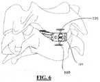
- implant 100 and anchors 130, 140are implanted from an anterior approach, as shown in FIG. 6 , the leading portion of jacket 108 is positioned in the posterior portion of the intervertebral disc space and the trailing portion of jacket 108 is positioned in the anterior portion of the intervertebral disc space.
- prosthesis implant 100 and anchors 130, 140may replicate the strength and stiffness of the natural anterior and posterior longitudinal ligaments to provide superior fixation of adjacent vertebral bodies.
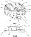
- FIGS. 9-14a set of instruments is shown in FIGS. 9-14 that are configured for installation of an implant 170 and anchors 150, 160, 164, 166 shown in FIGS. 15 and 16 .
- the instrumentsinclude an inserter 500 and an anchor tamp 600.
- FIGS. 15 and 16show implant 170 and anchors 150, 160, 164, 166, which are similar in nearly all respects to the above-described implant 100 and anchors 130, 140, and which are also described more thoroughly in United States Non-Provisional Patent Application Nos. 12/640,816 , 12/640,860 , and 12/640,892 .
- Implant 170includes, for example, a spacer 176 and a jacket 178 disposed thereabout. Spacer 176 includes chambers 177a, 177b, 177c that can be packed with graft material.
- Anchor 150is essentially identical to anchors 160, 164, 166 and is configured to engage the vertebral body and implant 170.
- anchors 150, 164are disposed on opposite sides of implant 170 from anchors 160, 166.
- Implant 170includes interconnection features 180, 182, 184, 186 that extend across spacer 176 and jacket 178 to mate with interconnection portions 152, 162, 168, 169, of anchors 150, 160, 164, 166, respectively.
- Anchor 150is generally elongate with a leading end and a trailing end opposite therefrom, with interconnection portion 152 extending therebetween. Interconnection portion 152 is shaped and sized to mate with interconnection feature 180 of implant 170.
- Anchor 150further includes a fixation portion 158 configured as a plate extending between leading and trailing ends 154, 156.
- Anchor 150also includes legs extending generally perpendicularly between interconnection portion 152 and fixation portion 158. The leading leg includes a cutting edge and a piercing tip capable of cutting through bone.
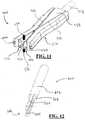
- inserter 500is capable of attaching securely to implant 170 and placing it into the intervertebral disc space, delivering the anchors 150, 160, 164, 166, and guiding anchor tamp 600.
- Inserter 500is an elongate instrument that includes a body 514 having a proximal end 502 and a distal end 504. At distal end 504, inserter 500 includes a concavely-curved surface 506 that is preferably shaped to match the curvature of implant 170. Surface 506 can be planar or otherwise shaped to more accurately match the contours of the implant with which it is utilized.
- a threaded rod 512runs through body 514 and is disposed between proximal end 502 and distal end 504 of inserter 500.
- Rod 512extends distally of surface 506, is engageable with a threaded aperture 174 of implant 170, and is controlled by a rotatable knob 516 located at proximal end 502 of inserter 500 that allows the user to tighten implant 170 to surface 506 of inserter 500, thus securing implant 170 rigidly in all six degrees of freedom with respect to inserter 500.
- Tabs 540a, 540balso protrude from surface 506 and engage with corresponding portions of implant 170.
- Proximal end 502 of inserter 500includes a handle 508 and a large face 526 capable of withstanding blows from a mallet to facilitate insertion of implant 170 when impaction is required. A surgeon may grasp and control the instrument at handle 508 without his/her hand or fingers coming into contact with soft tissues of the cervical spine during use of inserter 500.
- Inserter 500has superior longitudinal channels 518, 519 and inferior longitudinal channels 520, 521 located on superior surface 528 and inferior surface 530, respectively, of inserter 500 and being capable of containing, aligning, and slidably delivering anchors 150, 160, 164, 166 to engage with implant 170 and the adjacent vertebral bodies once implant 170 is inserted into the disc space.
- the pairs of channels 518, 519, 520, 521cross on their respective surfaces according to the orientation of the anchors 150, 160, 164, 166 with respect to implant 170.
- channels 518, 519, 520, 521may be oriented with respect to their respective surface 528, 530 at any angle with surface 506, and may be crossed, angled, or parallel.
- Channels 518, 519, 520, 521may also be angled with respect to their respective surface 528, 530 such that their depth extends along a direction that is perpendicular or angled or canted with their respective surface 528, 530. As shown in FIG. 11 , channels 518, 519, 520, 521 are each angled with their respective surface 528, 530. The angles of channels 518, 519, 520, 521 correspond with the orientation of the interconnection features of the implant, and determine the final positioning of the anchors. Channels 518, 519, 520, 521 are also used to guide tamp 600 when tapping the respective anchor into implant 170 and the adjacent vertebra. Tamp 600 accesses channels 518, 519, 520, 521 at a proximal face 542 of distal end 504, shown more clearly in FIG. 14 .
- inserter 500includes a post 538 on superior surface 528 and a similar post 539 on inferior surface 530.
- Posts 538, 539are configured to engage with the adjacent vertebral bodies to provide a stop for preventing over-insertion of inserter 500.
- Each post 538, 539is disposed on the respective superior and inferior surfaces 528, 530 so as not to cover or otherwise obstruct channels 518, 519, 520, 521.
- Inserter 500is preferably at least somewhat symmetrical about a horizontal plane parallel to and extending between superior and inferior surfaces 528, 530 such that inserter 500 may be utilized in the orientation depicted or in an inverted orientation. As implant 170 possesses a similar symmetry, inserter 500 can beneficially be connected with implant 170 in either orientation. Inserter 500 is also preferably at least somewhat symmetrical about a vertical plane that bisects superior and inferior surfaces 528, 530.
- Inserter 500is preferably constructed of metal, and may include two or more metals.
- body 514may be constructed of stainless steel while handle 508 is constructed of titanium, which may be color anodized.
- handle 508is constructed of titanium, which may be color anodized.
- any other material suitable for use during surgerymay be employed in the construction of inserter 500.
- the materials utilized in the construction of inserter 500are capable of being sterilized multiple times, so that the inserter may be utilized in multiple surgeries/procedures.
- tamp 600is a long instrument constructed preferably of stainless steel, and is used primarily for the insertion of anchors 150, 160, 164, 166 into the vertebral bodies. Tamp 600 includes a proximal end 622 and a distal end 602 with a lead edge 604 that may or may not match the conforming geometry on the proximal end of anchor 150. When assembled to the inserter 500, tamp 600 engages the proximal end of anchor 150 to controllably push anchor 150 into the vertebral body.
- the mating surfaces between tamp 600 and anchor 150can be of any configuration as long as tamp 600 may push anchor 150 distally when force is exerted at proximal end 622.
- Tamp 600has a profile that allows it to fit within channels 519, 520, 521, 522. Thus, sliding engagement is permitted between tamp 600 and inserter 500 to control the path of tamp 600 during insertion.
- a stop face 626is provided that separates a cutting portion 620 from a main body 612. Stop face 626 is configured to abut face 542 of inserter 500 during use of tamp 600 to prevent overinsertion of anchors 150, 160, 164, 166 into the vertebral bodies.
- tamp 600may be impacted similarly to the above described first embodiment on an impaction surface 624 at proximal end 622, as shown in FIG. 14 . Impaction of surface 624 aids in forcing distal end 602 of tamp 600, and accordingly, anchors 150, 160, 164, 166 into the bone.
- a cutteris not depicted with respect to the second embodiment, it is contemplated that a cutter may be provided having a similar construction to tamp 600 with the necessary cutting edges and/or needle tips.
- tamp 600may be provided with appropriate cutting edges to operate as both a cutter and a tamp.
- the tampwould first be utilized to cut the bone and thereafter utilized to insert the anchors in place.
- a method of inserting implant 170is similar in nature to the method described above.
- the methodmay begin with a surgeon being provided with a kit of differently sized and shaped implants and anchors and the surgeon selecting a particular implant and corresponding anchors according to the anatomy of the patient upon which the surgical procedure is to be performed.
- Selected implant 170is then attached to distal end 504 of inserter 500.
- threaded rod 512is inserted into threaded aperture 174 to secure implant 170 to inserter 500 in a particular orientation. Threaded rod 512 may be screwed into aperture 174 by the surgeon actuating knob 516.
- Implant 170 and inserter 500are now secured to one another such that manipulation of inserter 500 can ensure proper positioning of implant within the disc space.
- the intervertebral disc spaceis prepared by removing at least a portion of the intervertebral disc material. This can be done at this stage of the procedure or prior to the surgeon's selection or attachment of implant 170. With the appropriate portion of the disc space cleared, the surgeon aligns and inserts implant 170 into the disc space by manipulating inserter 500, preferably at handle 508 to allow for the area adjacent the disc space to remain free and clear so that the procedure can be appropriately observed. If necessary, face 526 at proximal end 502 of inserter 500 may be impacted by a surgical mallet or other device to allow for proper insertion and position of implant 170 between the adjacent, often collapsed, vertebrae. Posts 538, 539 may contact the adjacent vertebral bodies to prevent overinsertion of implant 170. To further aid in fusing implant 170 to the adjacent vertebrae, one or more of chambers 177a, 177b, 177c may be packed with bone graft material prior to insertion of implant 170 within the disc space.
- a cutter or, if tamp is provided with the appropriate blades, tamp 600may be used to cut entryways into the adjacent vertebrae (if so designed). This step is not necessary, as anchors 150, 160, 164, 166 are configured to pierce the uncut bone.
- Anchor 164is then loaded into longitudinal channel 519, which can also be described as a track on superior surface 528.
- the method of inserting an anchor according to the present inventionis herein described with respect to anchor 164, although more than one anchor may be inserted simultaneously.
- Interconnection element 152is disposed within channel 519, and tamp 600 is slidably attached to inserter 500 proximal of anchor 164 within channel 519 as well, with least lead edge 604 in contact with the trailing end of anchor 164.
- tamp 600As tamp 600 is advanced toward the vertebra, it forces anchor 164 along with it and eventually into contact with the bone. Tamp 600 is further advanced to fully insert anchor 164 into the vertebra such that the interconnection element of anchor 164 locks into place within interconnection feature 184 of implant 170.
- Stop face 626may abut surface 542 of inserter 500 during advancement to ensure that anchor 164 is not over-inserted.
- Anchor 164is eventually seated such that migration and backout are prevented between anchor 164 with respect to both implant 170 and the adjacent vertebra. Thus, axial and torsional movement between implant 170 and the adjacent vertebra are prevented.
- Anchors 150, 160, 166may be inserted in the same manner as described above, although with respect to different channels of inserter 500. Tamp 600 may be used first on a one anchor and subsequently on the others, or two or more tamps 600 may be utilized together. It is noted that tamp 600 is generally restrained in 5 degrees of freedom with respect to inserter 500 during insertion.
- implant 170 and anchors 150, 160, 164, 166are implanted from an anterior approach, as shown in FIG. 15 , the leading portion of jacket 178 is positioned in the posterior portion of the intervertebral disc space and the trailing portion of jacket 178 is positioned in the anterior portion of the intervertebral disc space.
- prosthesis implant 170 and anchors 150, 160, 164, 166may replicate the strength and stiffness of the natural anterior and posterior longitudinal ligaments to provide superior fixation of adjacent vertebral bodies.
- the instruments according to the present inventionare preferably constructed of metal, although other types of materials may be used that give the proper strength to the instruments. Such materials could be hard polymeric materials or other plastics. Of course any other material suitable for use during surgery may be employed in the construction of any of the instruments. Preferably, the materials utilized are capable of being sterilized multiple times, so that the instruments may be utilized in multiple surgeries/procedures.
Landscapes
- Health & Medical Sciences (AREA)
- Engineering & Computer Science (AREA)
- Biomedical Technology (AREA)
- Orthopedic Medicine & Surgery (AREA)
- Neurology (AREA)
- Transplantation (AREA)
- Heart & Thoracic Surgery (AREA)
- Oral & Maxillofacial Surgery (AREA)
- Cardiology (AREA)
- Vascular Medicine (AREA)
- Life Sciences & Earth Sciences (AREA)
- Animal Behavior & Ethology (AREA)
- General Health & Medical Sciences (AREA)
- Public Health (AREA)
- Veterinary Medicine (AREA)
- Physical Education & Sports Medicine (AREA)
- Prostheses (AREA)
- Surgical Instruments (AREA)
Description
- The present application claims the benefit of United States Provisional Patent Application No.
61/232,705 61/232,745 61/257,734 61/257,667 - The present invention relates to spinal surgery. More particularly, the present invention relates to surgical instruments and a method of using such instruments to insert an implant and anchors into the intervertebral disc space and the adjacent vertebrae.
- Back pain can be caused by many different things, including any one of several problems that affect the intervertebral discs of the spine. These disc problems include, for instance, degeneration, bulging, herniation, thinning of a disc, and abnormal movement, and the pain that is experienced is generally attributable to friction or pressure that inevitably occurs when one adjacent vertebra exerts uneven pressure or when both adjacent vertebrae exert such pressure on the disc. Oftentimes, disc problems lead to the vertebrae impinging on one of the very many nerves located in the spinal column.
- One surgical method commonly utilized to correct such disc problems is a fusion procedure where a surgeon fuses together adjacent vertebrae in single or multiple levels. Different methods (as well as apparatus for use in those methods) for such surgery have been developed for performance on cervical, thoracic, or lumbar vertebral bodies. These fusion procedures will be referred to herein as interbody fusion or "IF." Traditional IF techniques generally involve removing at least a portion of the troublesome disc from the patient, adding bone graft material into the interbody space between the vertebrae that flank the disc, and inserting a spinal implant device into the space to hold the graft material in place and to support the vertebrae while solid bone mass forms therebetween. Oftentimes, the steps of inserting an implant and bone graft material involve first packing the implant with the bone graft material, and thereafter implanting that construct.
- While IF is a long-established technique for correcting the aforementioned disc problems, it is one that is constantly updated. For instance, different implants have been created to suit specific needs, and methods involving the insertion of such implants and the preparation of the vertebrae to receive same are constantly evolving. One major issue that has existed and will continue to exist is the fact that implants inserted into the disc space often take an extended period of time to achieve permanent fusion between the adjacent vertebrae. This leads to long recovery periods for the patient. Certain implants also fail to achieve a degree of fusion that permanently eliminates flexion, extension, and axial movement between the two adjacent vertebrae. This may allow for the initial fusion created by the implant to wear down in certain aspects, which in turn allows for future discomfort to the patient and potentially follow-up surgical procedures.
US 2009/005870 refers to an intervertebral fusion cage including an upper component and a lower component. In use, these component halves are inserted into the disc space in a sequential fashion and are assembled in situ. An insertion instrument including a rail, a top pusher and a bottom rod is disclosed. - Thus, there exists a need for a spinal implant, method of using the implant, and related instrumentation for such method that improves upon these shortcomings.
- A first aspect of the present invention is a surgical instrument for inserting a spinal implant in the intervertebral disc space between two adjacent vertebrae and an anchor engageable with the implant and an adjacent vertebra comprising an engagement portion including a superior surface, an inferior surface, a distal engagement surface for interfacing with the implant, and a pair of tracks on at least one of the superior and inferior surfaces for slidably translating the anchor toward the engagement surface, wherein the pair of tracks cross on the at least one of the superior and inferior surfaces, and a handle portion connected to the engagement portion having a proximal surface for impaction.
- In accordance with certain embodiments of this first aspect, the instrument may include a rod extending from the engagement surface. The rod may be threadably engageable with a corresponding aperture in the implant. The handle portion may include a knob connected with the rod for threading the rod into the aperture in the implant. The engagement surface may be curved according to the contour of the implant. The instrument may further include a shoulder extending from at least one of the superior and inferior surfaces of the engagement portion. The instrument may further include connection features on lateral sides of the engagement portion for connection to additional surgical instruments. The connection features may include channels. The pair of tracks may be embedded within the surface. There may be provided a first pair of tracks on the superior surface and a second pair of tracks on the inferior surface.
- There is provided a kit of surgical instruments for inserting a spinal implant in the intervertebral disc space between two adjacent vertebrae and an anchor engageable with the implant and an adjacent vertebra comprising an inserter having an engagement portion and a handle portion, the engagement portion including a superior surface, an inferior surface, a distal engagement surface for interfacing with the implant, and a track on at least one of the superior and inferior surfaces for slidably translating the anchor toward the engagement surface, and the handle portion connected to the engagement portion and having a proximal surface for impaction, and a tamp slidably engageable with the inserter in contact with the anchor to force the anchor into engagement with the implant and the adjacent vertebra.
- The kit may further include a cutter slidably engageable with the inserter for piercing an adjacent vertebra, the cutter having at least one blade edge for cutting bone. The tamp and the cutter may be slidably mountable within channels on the inserter. The tamp and the cutter may be slidably mountable within the track. The tamp and the cutter may each include a proximal surface for impaction. The tamp may include at least one blade edge for cutting bone.
- There is provided a method of inserting an implant in the intervertebral disc space between two adjacent vertebrae and an anchor engageable with the implant and an adjacent vertebra comprising the steps of attaching a distal end of an inserter to the implant, inserting the implant into the disc space by manipulating the inserter, inserting an anchor into engagement with the implant and the adjacent vertebra, and sliding a tamp along the inserter in contact with the anchor to force the anchor into engagement with the implant and the adjacent vertebra.
- The step of sliding the tamp may include impacting a proximal end of the tamp. The method may further include the step of cutting an entryway into the adjacent vertebra for the anchor by sliding a cutter along the inserter and piercing the opposing adjacent vertebra. The method may further include the step of cutting an entryway into the adjacent vertebra for the anchor by sliding the tamp along the inserter and piercing the opposing adjacent vertebra. The step of attaching may include securing the implant to the distal end of the inserter by inserting a rod of the inserter into an aperture of the implant. The step of inserting the rod may include screwing a threaded portion of the rod into a threaded portion of the aperture. The step of screwing may include tightening the threaded rod by way of a knob disposed at a handle of the inserter. The step of inserting the implant may include impacting a proximal end of the inserter. The step of inserting the anchor may include locking the anchor to the implant to prevent migration and backout of the anchor with respect to the implant. The step of inserting the anchor may include locking the anchor to the adjacent vertebra to prevent migration and backout of the anchor with respect to the adjacent vertebra. The anchor may prevent axial movement an axis of the spine between the implant and the adjacent vertebra along. The anchor may prevent torsional movement between the implant and the adjacent vertebra.
- The method may further include the steps of inserting a second anchor into engagement with the implant and the opposing adjacent vertebra, and sliding the tamp along the inserter in contact with second anchor to force the anchor into engagement with the implant and the opposing adjacent vertebra. The method may further include cutting an entryway into the opposing adjacent vertebra for the second anchor by sliding a cutter along the inserter and piercing the opposing adjacent vertebra. The method may further include inserting third and fourth anchors into engagement with the implant and adjacent vertebrae such that two anchors are engaged at a superior surface of the implant and two anchors are engaged at an inferior surface of the implant. The method may further include the step of preparing the intervertebral disc space by removing at least a portion of the intervertebral disc. The method may further include packing a chamber of the implant with graft material. The method may further include the steps of providing a kit of differently sized and shaped implants and anchors, and selecting an implant and an anchor according to the anatomy of the patient.
FIG. 1 is a perspective view of an implant and an anchor connected to an insertion instrument having an inserter and two tamps.FIG. 2 is a perspective view of the inserter and a tamp shown inFIG. 1 .FIGS. 3A and 3B are top plan views of the proximal and distal ends, respectively, of the inserter and tamp shown inFIG. 1 .FIG. 4 is a perspective view of the distal end of a pilot cutter.FIG. 5 is a perspective view of the distal end of the tamp shown inFIG. 1 .FIG. 6 is a perspective view of the implant and two anchors shown inFIG. 1 inserted into an intervertebral disc space between two adjacent vertebrae.FIG. 7 is a perspective view of the implant and two anchors shown inFIG. 6 .FIG. 8 is a side elevational view of the anchor shown inFIG. 1 .FIG. 9 is a perspective view of an implant connected to an inserter in accordance with an embodiment of the present invention.FIG. 10 is a top plan view of the inserter shown inFIG. 9 .FIG. 11 is a perspective view of the distal end of the inserter shown inFIG. 9 .FIG. 12 is a perspective view of a distal end of a tamp in accordance with the second embodiment.FIG. 13 is a perspective view of the implant attached to the inserter shown inFIG. 9 inserted into an intervertebral disc space between two adjacent vertebrae.FIG. 14 is a perspective view of an anchor inserted in the intervertebral disc space by the inserter shown inFIG. 9 and the tamp shown inFIG. 12 .FIG. 15 is a perspective view of the implant shown inFIG. 13 and four anchors inserted into an intervertebral disc space between two adjacent vertebrae.FIG. 16 is a perspective view of the implant and two anchors shown inFIG. 15 .- A set of instruments is shown in
FIGS. 1-5 that are configured for installation of animplant 100 and anchors 130, 140 shown alone inFIGS. 7 and 8 . The instruments include aninserter 200, apilot cutter 300, and an anchor tamp 400. - By way of reference to certain aspects of the below-described instruments,
FIGS. 7 and 8 show implant 100 and anchors 130, 140, which are described more thoroughly in United States Non-Provisional Patent Application Nos.12/640,816 12/640,860 12/640,892 Implant 100 includes, for example, aspacer 106 and ajacket 108 disposed thereabout to provide added strength and support forimplant 100.Spacer 106 includes chambers 107a, 107b that can be packed with graft material.Anchor 130 is essentially identical to anchor 140 and is configured to engage the vertebral bodies adjacent the intervertebral disc space in which implant 100 is inserted. In the implanted position, anchors 130, 140 are disposed on opposite sides of thespacer 100.Implant 100 includes interconnection features 110, 112 that extend acrossspacer 106 andjacket 108 to mate withinterconnection portions anchors Interconnection portions anchors implant 100, so that spinal loads are distributed from one vertebra to another throughanchors jacket 108.Anchor 130 is generally elongate with aleading end 134 and a trailingend 136 opposite therefrom, withinterconnection portion 132 extending therebetween.Interconnection portion 132 is shaped and sized to mate withinterconnection feature 110 ofimplant 100, so as to slidably connectanchor 130 withimplant 100.Anchor 130 further includes afixation portion 138 configured as a plate extending between leading and trailing ends 134, 136.Anchor 130 also includeslegs 135, 137 extending generally perpendicularly betweeninterconnection portion 132 andfixation portion 138.Leg 135, which is disposed toward leadingend 134 ofanchor 130, includes acutting edge 139 and a piercingtip 133 capable of cutting through bone. Inserter 200 is capable of attaching securely to implant 100 and placing it into the intervertebral disc space, delivering theanchors pilot cutter 300 and anchor tamp 400.Inserter 200 is an elongate instrument that includes abody 214 having a proximal end 202 (best shown inFIG. 3A ) and adistal end 204. Atdistal end 204,inserter 200 includes a concavely-curved surface 206 that is preferably shaped to match the curvature ofimplant 100.Surface 206 can be planar or otherwise shaped to more accurately match the contours of the implant with which it is utilized. Asmooth pin 210 extends fromsurface 206 that interfaces with an appropriatelysized aperture 102 onimplant 100 to locate and couple implant 100 toinserter 200.Pin 210 is preferably dimensioned to correspond withaperture 102 such that a tight fit is formed therebetween. A threadedrod 212 is disposed betweenproximal end 202 anddistal end 204 and runs throughbody 214 ofinserter 200.Rod 212 is engaged with a threadedaperture 104 ofimplant 100 and is controlled by a thumb wheel 216 (best shown inFIG. 3A ) located atproximal end 202 ofinserter 200 that allows the user to tightenimplant 100 to face 208 ofinserter 200, thus securingimplant 100 rigidly in all six degrees of freedom with respect toinserter 200.- As shown in
FIG. 3A ,proximal end 202 ofinserter 200 includes ahandle 208 and alarge face 226 capable of withstanding blows from a mallet to facilitate insertion ofimplant 100 when impaction is required. A surgeon may grasp and control the instrument athandle 208 without his/her hand or fingers coming into contact with soft tissues of the cervical spine during use ofinserter 200. Inserter 200 has a superiorlongitudinal channel 218 and an inferiorlongitudinal channel 220 located onsuperior surface 228 andinferior surface 230, respectively, ofinserter 200 and being capable of containing, aligning, and slidably deliveringanchors implant 100 and the adjacent vertebral bodies onceimplant 100 is inserted into the disc space.Inserter 200 also includesflanges 222, 224 on a lateral side ofinserter 200 that define achannel 223 capable of slidably mating with conforming features oncutter 300 and tamp 400 to allow for translation along a longitudinal axis ofinserter 200. Similar flanges and a channel are disposed on the opposed lateral side ofinserter 200.- Also at its
distal end 204,inserter 200 includes a pair ofshoulders 232a, 232b onsuperior surface 228 and a similar pair of shoulders 234a, 234b oninferior surface 230.Shoulders 232a, 232b, 234a, 234b are configured to engage withcutter 300 and tamp 400 to provide a stop for preventing such instruments and implant 100 from advancing too far into the intervertebral space or adjacent vertebral bodies. Each pair of shoulders is disposed on the respective superior andinferior surfaces longitudinal channels adjacent channels anchors shoulders 232a, 232b, 234a, 234b without coming into contact with same. Inserter 200 is preferably at least somewhat symmetrical about a horizontal plane parallel to and extending between superior andinferior surfaces inserter 200 may be utilized in the orientation depicted or in an inverted orientation. Asimplant 100 possesses a similar symmetry,inserter 200 can be connected withimplant 100 in either orientation. In that regard, it is also beneficial thataperture 102 ofimplant 100 be threaded as well as threadedaperture 104 so thatinserter 200 can be properly engaged and locked to implant 100 in either orientation. Of course,smooth pin 210 ofinserter 200 can be configured to engage a aperture, threaded or not, to aid in securing and orientingimplant 100 with respect toinserter 200.Inserter 200 is also preferably at least somewhat symmetrical about a vertical plane that bisects superior andinferior surfaces Inserter 200 is preferably constructed of metal, and may include two or more metals. For example,body 214 may be constructed of stainless steel whilehandle 208 is constructed of titanium, which may be color anodized. Of course any other material suitable for use during surgery may be employed in the construction ofinserter 200. Preferably, the materials utilized in the construction ofinserter 200 are capable of being sterilized multiple times, so that the inserter may be utilized in multiple surgeries/procedures.- Shown in
FIG. 4 ,cutter 300 is an elongate instrument preferably constructed of stainless steel, and is primarily used for cutting an initial pathway through the vertebral bodies, through which anchors 130, 140 can be led. In particular,cutter 300 is configured to cut a starter channel with minimal force, thereby reducing the total amount of trauma to the vertebral bodies asanchors distal end 306,cutter 300 includes ablade surface 304 and a trocar-type needle tip 302 extending distally from a front face 314. Additional blades, such ablade 316, can be positioned aboutblade surface 304 andneedle tip 302 as necessary to aid in cutting the vertebral bodies. Multiple blade surfaces or needle tips may also be included as necessary according to the construction of the associated implant and anchors.Blade surface 304 is similar in geometry to cuttingedge 139 ofanchor 130, minimizing the total force required to insertanchor 130.Needle tip 302 is also geometrically similar to piercingtip 133. Cutter 300 includeswings 308, 310 extending from amain body 312 that engage with channels, such aschannel 223, ininserter 200 to allow for sliding engagement betweencutter 300 andinserter 200 to control the path of thecutter 300 during insertion. Front face 314 is configured toabut shoulders 232a, 232b or 234a, 234b during use ofcutter 300 to prevent overextendingcutter 300 into the vertebral bodies. Once mated withinserter 200,cutter 300 may be impacted on a surface (not shown) at its proximal end, such surface being disposed adjacent to and preferably proximally offace 226 of proximal end ofinserter 200. Impaction of the surface at the proximal end ofcutter 300 aids in forcingblade surface 304,needle tip 302, andblade 316 into the bone.Cutter 300 includes asurface 318 alongmain body 312 that is disposed generally parallel tosuperior surface 228 or inferior surface 330 whencutter 300 is engaged withinserter 200. Handle 208 ofinserter 200 may include asurface 236, as shown inFIG. 3A , that extends above superior surface 228 (or alternatively, inferior surface 330) such thatsurface 318 ofcutter 300 andsurface 236 ofhandle 208 may be substantially coplanar whencutter 300 is engaged withinserter 200. Thus, a surgeon may grasp the combination ofcutter 300 andinserter 200 athandle 208, andmain body 312 ofcutter 300 will not protrude fromhandle 208, which might make grasping the instruments awkward or uncomfortable. This configuration also allowscutter 300 to easily translate with respect toinserter 200 during impaction ofcutter 300 while the surgeon maintains his or her grip aroundhandle 208.- As shown in
FIG. 5 , tamp 400 is an elongate, thin instrument constructed of stainless steel, and is used primarily for the insertion ofanchors distal end 402 that matches the conforming geometry on the proximal end ofanchor 130, and more particularly, with respect to the proximal portions of leg 137 andfixation portion 138. When assembled to theinserter 200, tamp 400 engages the proximal end ofanchor 130 to controllably pushanchor 130 into the vertebral body.Distal end 402 includes alead edge 404, asecondary edge 406, and an angledtop portion 408.Lead edge 404 and angledtop portion 408 are configured to mate with leg 137 and fixedportion 138, whilesecondary edge 406 is configured to mate with the proximal end ofinterconnection element 132, which extends further proximally than the other components ofanchor 130. The mating surfaces between tamp 400 andanchor 130 can be of any configuration as long as tamp 400 may pushanchor 130 distally when force is exerted at aproximal end 410 of tamp 400. Tamp 400 may conform to the mating surfaces ofanchor 130 or it may not. As described below with respect to the second embodiment, tamp 400 may be provided with appropriate cutting edges to operate as both a cutter and a tamp. Of course, in such a case, the tamp would first be utilized to cut the bone and thereafter utilized to insert the anchors in place. - Tamp 400 includes
wings wings channel 223, ininserter 200 in a similar manner ascutter 300. Thus, sliding engagement is permitted between tamp 400 andinserter 200 to control the path of tamp 400 during insertion. Afront face 420 is also included atdistal end 402 of tamp 400 and is configured toabut shoulders 232a, 232b or 234a, 234b during use of tamp 400 to prevent overinsertion ofanchors inserter 200, tamp 400 may be impacted similarly tocutter 300 on animpaction surface 412 atproximal end 410, as shown inFIG. 3A . Impaction ofsurface 412 aids in forcingdistal end 402 of tamp 400, and accordingly, anchors 130, 140 into the bone. - Also similar to
cutter 300, tamp 400 includes asurface 422 along main body 418 that is disposed generally parallel tosuperior surface 228 or inferior surface 330 when tamp 400 is engaged withinserter 200.Surface 422 andsurface 236 ofhandle 208 may be substantially coplanar when tamp 400 is engaged withinserter 200. Thus, a surgeon may grasp the combination of tamp 400 andinserter 200 athandle 208, and main body 418 will not protrude fromhandle 208, which might make grasping the instruments awkward or uncomfortable. Instead, tamp 400 may easily translate with respect toinserter 200 during impaction of tamp 400 while the surgeon maintains his or her grip aroundhandle 208. - A method of inserting
implant 100 may begin with a surgeon being provided with a kit of differently sized and shaped implants and anchors and the surgeon selecting a particular implant and corresponding anchors according to the anatomy of the patient upon which the surgical procedure is to be performed. Selectedimplant 100 is then attached todistal end 204 ofinserter 200. Preferably,smooth pin 210 is inserted intoaperture 102 of implant to secureimplant 100 toinserter 200 in a particular orientation. Threadedrod 212 may also or alternatively be inserted into threadedaperture 104 for additional attachment. Threadedrod 212 may be screwed intoaperture 104 by the surgeonactuating thumb wheel 216 disposed athandle 208.Implant 100 andinserter 200 are now secured to one another such that manipulation ofinserter 200 can ensure proper positioning of implant within the disc space. - The intervertebral disc space is prepared by removing at least a portion of the intervertebral disc material. This can be done at this stage of the procedure or prior to the surgeon's selection or attachment of
implant 100. With the appropriate portion of the disc space cleared, the surgeon aligns and inserts implant 100 into the disc space by manipulatinginserter 200, preferably athandle 208 to allow for the area adjacent the disc space to remain free and clear so that the procedure can be appropriately observed. If necessary, face 226 atproximal end 202 ofinserter 200 may be impacted by a surgical mallet or other device to allow for proper insertion and position ofimplant 100 between the adjacent, often collapsed, vertebrae. To further aid in fusingimplant 100 to the adjacent vertebrae, one or both of chambers 107a, 107b may be packed with bone graft material prior to insertion ofimplant 100 within the disc space. - Entryways for
anchors distal end 204 ofinserter 200 is still engaged toimplant 100 and positioned adjacent to the disc space,cutter 300 is slidably attached to inserter 200 withwings 308, 310 disposed inchannel 223 and a channel on the opposing lateral surface ofinserter 200.Cutter 300 is advanced toward the respective vertebra andneedle tip 302,blade surface 304, andblade 316 are used to pierce an entryway into the bone. A surgical mallet or other device may be used to strike a proximal end ofcutter 300 protruding proximally ofhandle 208 to assist in preparing the entryway in the bone. Front face 314 preferablycontacts shoulders 232a, 232b to prevent cutter from being inserted too far into the vertebra, although it is not necessary thatcutter 300 be inserted to a depth that requires contact between front face 314 andshoulders 232a, 232b.Cutter 300 is then disengaged from the bone andinserter 200. Anchor 130 is then loaded intolongitudinal channel 218, which can also be described as a track onsuperior surface 228.Interconnection element 132 is disposed withinchannel 218, and tamp 400 is slidably attached to inserter 200 proximal ofanchor 130 withwings channel 223 and a channel on the opposing lateral surface ofinserter 200.Inserter 200 may be alternatively configured to allow for side loading ofanchor 130 so that tamp 400 may be pre-attached toinserter 200. At leastlead edge 404, and preferablysecondary edge 406,contact trailing end 136 ofanchor 130. As tamp 400 is advanced toward the vertebra, it forcesanchor 130 along with it and eventually into contact with the bone. The maintained alignment ofinserter 200 with the vertebra and the configuration ofcutter 300 ensure thatanchor 130 is aligned with the pre-cut entryway as it contacts the bone. Tamp 400 is further advanced to fully insertanchor 130 into the vertebra such thatinterconnection element 132 ofanchor 130 locks into place withininterconnection feature 110 ofimplant 100.Shoulders 232a, 232b may abutfront face 420 of tamp 400 during advancement to ensure thatanchor 130 is not over-inserted.Anchor 130 is eventually seated such that migration and backout are prevented betweenanchor 130 with respect to bothimplant 100 and the adjacent vertebra. Thus, axial and torsional movement betweenimplant 100 and the adjacent vertebra are prevented.Anchor 140 may be inserted in the same manner as described above, although with respect toinferior face 230 ofinserter 200.Cutter 300 may be used sequentially or twocutters 300 may be utilized and employed simultaneously to cut the respective entryways. Likewise, tamp 400 may be used first onanchor 130 and subsequently onanchor 140, or twotamps 400 may be utilized together, such as shown inFIG. 1 . It is noted that tamp 400 andpilot cutter 300 are generally restrained in 5 degrees of freedom with respect toinserter 200 during insertion.- After tamp 400 is disengaged from
inserter 200, threadedrod 212 is unthreaded fromimplant 100, again usingthumb wheel 216.Inserter 200 is then removed from the surgical site, leavingimplant 100 and anchors 130, 140 in position as shown inFIG. 6 . Whenimplant 100 and anchors 130, 140 are implanted from an anterior approach, as shown inFIG. 6 , the leading portion ofjacket 108 is positioned in the posterior portion of the intervertebral disc space and the trailing portion ofjacket 108 is positioned in the anterior portion of the intervertebral disc space. In this arrangement,prosthesis implant 100 and anchors 130, 140 may replicate the strength and stiffness of the natural anterior and posterior longitudinal ligaments to provide superior fixation of adjacent vertebral bodies. - In accordance with an embodiment of the present invention, a set of instruments is shown in
FIGS. 9-14 that are configured for installation of animplant 170 and anchors 150, 160, 164, 166 shown inFIGS. 15 and 16 . The instruments include aninserter 500 and an anchor tamp 600. - With reference to certain aspects of the below-described instruments,
FIGS. 15 and 16 show implant 170 and anchors 150, 160, 164, 166, which are similar in nearly all respects to the above-describedimplant 100 and anchors 130, 140, and which are also described more thoroughly in United States Non-Provisional Patent Application Nos.12/640,816 12/640,860 12/640,892 Implant 170 includes, for example, aspacer 176 and a jacket 178 disposed thereabout.Spacer 176 includes chambers 177a, 177b, 177c that can be packed with graft material.Anchor 150 is essentially identical toanchors implant 170. In the implanted position, anchors 150, 164 are disposed on opposite sides ofimplant 170 fromanchors 160, 166.Implant 170 includes interconnection features 180, 182, 184, 186 that extend acrossspacer 176 and jacket 178 to mate withinterconnection portions anchors Anchor 150 is generally elongate with a leading end and a trailing end opposite therefrom, withinterconnection portion 152 extending therebetween.Interconnection portion 152 is shaped and sized to mate withinterconnection feature 180 ofimplant 170.Anchor 150 further includes afixation portion 158 configured as a plate extending between leading and trailing ends 154, 156.Anchor 150 also includes legs extending generally perpendicularly betweeninterconnection portion 152 andfixation portion 158. The leading leg includes a cutting edge and a piercing tip capable of cutting through bone. - Shown in
FIGS. 9-11 ,inserter 500 is capable of attaching securely to implant 170 and placing it into the intervertebral disc space, delivering theanchors Inserter 500 is an elongate instrument that includes abody 514 having aproximal end 502 and adistal end 504. Atdistal end 504,inserter 500 includes a concavely-curved surface 506 that is preferably shaped to match the curvature ofimplant 170.Surface 506 can be planar or otherwise shaped to more accurately match the contours of the implant with which it is utilized. A threadedrod 512 runs throughbody 514 and is disposed betweenproximal end 502 anddistal end 504 ofinserter 500.Rod 512 extends distally ofsurface 506, is engageable with a threadedaperture 174 ofimplant 170, and is controlled by arotatable knob 516 located atproximal end 502 ofinserter 500 that allows the user to tightenimplant 170 to surface 506 ofinserter 500, thus securingimplant 170 rigidly in all six degrees of freedom with respect toinserter 500.Tabs 540a, 540b also protrude fromsurface 506 and engage with corresponding portions ofimplant 170. Proximal end 502 ofinserter 500 includes ahandle 508 and alarge face 526 capable of withstanding blows from a mallet to facilitate insertion ofimplant 170 when impaction is required. A surgeon may grasp and control the instrument athandle 508 without his/her hand or fingers coming into contact with soft tissues of the cervical spine during use ofinserter 500.Inserter 500 has superiorlongitudinal channels longitudinal channels superior surface 528 andinferior surface 530, respectively, ofinserter 500 and being capable of containing, aligning, and slidably deliveringanchors implant 170 and the adjacent vertebral bodies onceimplant 170 is inserted into the disc space. The pairs ofchannels anchors implant 170. Of course,channels respective surface surface 506, and may be crossed, angled, or parallel.Channels respective surface respective surface FIG. 11 ,channels respective surface channels Channels implant 170 and the adjacent vertebra. Tamp 600accesses channels proximal face 542 ofdistal end 504, shown more clearly inFIG. 14 .- Also at its
distal end 504,inserter 500 includes apost 538 onsuperior surface 528 and asimilar post 539 oninferior surface 530.Posts inserter 500. Eachpost inferior surfaces channels Inserter 500 is preferably at least somewhat symmetrical about a horizontal plane parallel to and extending between superior andinferior surfaces inserter 500 may be utilized in the orientation depicted or in an inverted orientation. Asimplant 170 possesses a similar symmetry,inserter 500 can beneficially be connected withimplant 170 in either orientation.Inserter 500 is also preferably at least somewhat symmetrical about a vertical plane that bisects superior andinferior surfaces Inserter 500 is preferably constructed of metal, and may include two or more metals. For example,body 514 may be constructed of stainless steel whilehandle 508 is constructed of titanium, which may be color anodized. Of course any other material suitable for use during surgery may be employed in the construction ofinserter 500. Preferably, the materials utilized in the construction ofinserter 500 are capable of being sterilized multiple times, so that the inserter may be utilized in multiple surgeries/procedures.- As shown in
FIGS 12 and14 , tamp 600 is a long instrument constructed preferably of stainless steel, and is used primarily for the insertion ofanchors proximal end 622 and a distal end 602 with a lead edge 604 that may or may not match the conforming geometry on the proximal end ofanchor 150. When assembled to theinserter 500, tamp 600 engages the proximal end ofanchor 150 to controllably pushanchor 150 into the vertebral body. The mating surfaces between tamp 600 andanchor 150 can be of any configuration as long as tamp 600 may pushanchor 150 distally when force is exerted atproximal end 622. - Tamp 600 has a profile that allows it to fit within
channels inserter 500 to control the path of tamp 600 during insertion. Astop face 626 is provided that separates a cuttingportion 620 from amain body 612. Stopface 626 is configured toabut face 542 ofinserter 500 during use of tamp 600 to prevent overinsertion ofanchors inserter 500, tamp 600 may be impacted similarly to the above described first embodiment on animpaction surface 624 atproximal end 622, as shown inFIG. 14 . Impaction ofsurface 624 aids in forcing distal end 602 of tamp 600, and accordingly, anchors 150, 160, 164, 166 into the bone. - While a cutter is not depicted with respect to the second embodiment, it is contemplated that a cutter may be provided having a similar construction to tamp 600 with the necessary cutting edges and/or needle tips. Alternatively, tamp 600 may be provided with appropriate cutting edges to operate as both a cutter and a tamp. Of course, in such a case, the tamp would first be utilized to cut the bone and thereafter utilized to insert the anchors in place.
- A method of inserting
implant 170 is similar in nature to the method described above. The method may begin with a surgeon being provided with a kit of differently sized and shaped implants and anchors and the surgeon selecting a particular implant and corresponding anchors according to the anatomy of the patient upon which the surgical procedure is to be performed. Selectedimplant 170 is then attached todistal end 504 ofinserter 500. Preferably, threadedrod 512 is inserted into threadedaperture 174 to secureimplant 170 toinserter 500 in a particular orientation. Threadedrod 512 may be screwed intoaperture 174 by thesurgeon actuating knob 516.Implant 170 andinserter 500 are now secured to one another such that manipulation ofinserter 500 can ensure proper positioning of implant within the disc space. - The intervertebral disc space is prepared by removing at least a portion of the intervertebral disc material. This can be done at this stage of the procedure or prior to the surgeon's selection or attachment of
implant 170. With the appropriate portion of the disc space cleared, the surgeon aligns and inserts implant 170 into the disc space by manipulatinginserter 500, preferably athandle 508 to allow for the area adjacent the disc space to remain free and clear so that the procedure can be appropriately observed. If necessary, face 526 atproximal end 502 ofinserter 500 may be impacted by a surgical mallet or other device to allow for proper insertion and position ofimplant 170 between the adjacent, often collapsed, vertebrae.Posts implant 170. To further aid in fusingimplant 170 to the adjacent vertebrae, one or more of chambers 177a, 177b, 177c may be packed with bone graft material prior to insertion ofimplant 170 within the disc space. - At this point, a cutter or, if tamp is provided with the appropriate blades, tamp 600 may be used to cut entryways into the adjacent vertebrae (if so designed). This step is not necessary, as
anchors Anchor 164 is then loaded intolongitudinal channel 519, which can also be described as a track onsuperior surface 528. The method of inserting an anchor according to the present invention is herein described with respect toanchor 164, although more than one anchor may be inserted simultaneously.Interconnection element 152 is disposed withinchannel 519, and tamp 600 is slidably attached to inserter 500 proximal ofanchor 164 withinchannel 519 as well, with least lead edge 604 in contact with the trailing end ofanchor 164. As tamp 600 is advanced toward the vertebra, it forcesanchor 164 along with it and eventually into contact with the bone. Tamp 600 is further advanced to fully insertanchor 164 into the vertebra such that the interconnection element ofanchor 164 locks into place withininterconnection feature 184 ofimplant 170. Stopface 626 may abut surface 542 ofinserter 500 during advancement to ensure thatanchor 164 is not over-inserted.Anchor 164 is eventually seated such that migration and backout are prevented betweenanchor 164 with respect to bothimplant 170 and the adjacent vertebra. Thus, axial and torsional movement betweenimplant 170 and the adjacent vertebra are prevented.Anchors inserter 500. Tamp 600 may be used first on a one anchor and subsequently on the others, or two ormore tamps 600 may be utilized together. It is noted that tamp 600 is generally restrained in 5 degrees of freedom with respect toinserter 500 during insertion.- After tamp 600 is disengaged from
inserter 500, threadedrod 512 is unthreaded fromimplant 170 usingknob 516.Inserter 500 is then removed from the surgical site, leavingimplant 170 and anchors 150, 160, 164, 166 in position as shown inFIG. 15 . Whenimplant 170 and anchors 150, 160, 164, 166 are implanted from an anterior approach, as shown inFIG. 15 , the leading portion of jacket 178 is positioned in the posterior portion of the intervertebral disc space and the trailing portion of jacket 178 is positioned in the anterior portion of the intervertebral disc space. In this arrangement,prosthesis implant 170 and anchors 150, 160, 164, 166 may replicate the strength and stiffness of the natural anterior and posterior longitudinal ligaments to provide superior fixation of adjacent vertebral bodies. - The instruments according to the present invention are preferably constructed of metal, although other types of materials may be used that give the proper strength to the instruments. Such materials could be hard polymeric materials or other plastics. Of course any other material suitable for use during surgery may be employed in the construction of any of the instruments. Preferably, the materials utilized are capable of being sterilized multiple times, so that the instruments may be utilized in multiple surgeries/procedures.
- Although the invention herein has been described with reference to particular embodiments, it is to be understood that these embodiments are merely illustrative of the principles and applications of the present invention. It is therefore to be understood that numerous modifications may be made to the illustrative embodiments and that other arrangements may be devised without departing from the spirit and scope of the present invention as defined by the appended claims.
Claims (11)
- A surgical instrument for inserting a spinal implant (100, 170) in the intervertebral disc space between two adjacent vertebrae and an anchor (130, 140, 150, 160, 164, 166) engageable with the implant and an adjacent vertebra, the instrument comprising:an engagement portion including a superior surface (228, 528), an inferior surface (230, 530), and a distal engagement surface (206, 506) for interfacing with the implant; anda handle portion (208, 508) connected to the engagement portion having a proximal surface (226, 526) for impaction,characterized in that a pair of tracks (518, 519; 520, 521) is provided on at least one of the superior and inferior surfaces for slidably translating the anchor toward the engagement surface, wherein the pair of tracks cross on the at least one of the superior and inferior surfaces.
- The instrument of claim 1, further comprising a rod (212, 512) extending from the engagement surface.
- The instrument of claim 2, wherein the handle portion includes a knob (216, 516) connected with the rod for threading the rod into an aperture in the implant.
- The instrument of claim 1, wherein the engagement surface is curved according to the contour of the implant.
- The instrument of claim 1, further comprising a shoulder (232a; 232b; 234a; 234b) extending from at least one of the superior and inferior surfaces of the engagement portion.
- The instrument of claim 1, wherein the pair of tracks is embedded within the surface.
- The instrument of claim 1, wherein the pair of tracks includes a first pair of tracks on the superior surface and a second pair of tracks on the inferior surface.
- A kit of surgical instruments comprising:the surgical instrument of claim 1; anda tamp (400, 600) slidably engageable with the surgical instrument in contact with the anchor to force the anchor into engagement with the implant and the adjacent vertebra.
- The kit of claim 8, wherein the tamp includes at least one blade edge for cutting bone.
- The kit of claim 8, further comprising a cutter (300) slidably engageable with the surgical instrument for piercing an adjacent vertebra, the cutter having at least one blade edge (304; 316) for cutting bone.
- A kit of surgical instruments comprising:the surgical instrument of claim 1; anda cutter (300) slidably engageable with the surgical instrument for piercing an adjacent vertebra, the cutter having at least one blade edge for cutting bone.
Priority Applications (1)
| Application Number | Priority Date | Filing Date | Title |
|---|---|---|---|
| EP16171066.0AEP3115026B1 (en) | 2009-08-10 | 2010-08-10 | Surgical instrument |
Applications Claiming Priority (5)
| Application Number | Priority Date | Filing Date | Title |
|---|---|---|---|
| US23270509P | 2009-08-10 | 2009-08-10 | |
| US23274509P | 2009-08-10 | 2009-08-10 | |
| US25773409P | 2009-11-03 | 2009-11-03 | |
| US25766709P | 2009-11-03 | 2009-11-03 | |
| EP10744797.1AEP2464315B8 (en) | 2009-08-10 | 2010-08-10 | Intervertebral implant with integrated fixation |
Related Parent Applications (2)
| Application Number | Title | Priority Date | Filing Date |
|---|---|---|---|
| EP10744797.1ADivisionEP2464315B8 (en) | 2009-08-10 | 2010-08-10 | Intervertebral implant with integrated fixation |
| EP10744797.1ADivision-IntoEP2464315B8 (en) | 2009-08-10 | 2010-08-10 | Intervertebral implant with integrated fixation |
Related Child Applications (1)
| Application Number | Title | Priority Date | Filing Date |
|---|---|---|---|
| EP16171066.0ADivisionEP3115026B1 (en) | 2009-08-10 | 2010-08-10 | Surgical instrument |
Publications (3)
| Publication Number | Publication Date |
|---|---|
| EP2835113A2 EP2835113A2 (en) | 2015-02-11 |
| EP2835113A3 EP2835113A3 (en) | 2015-05-20 |
| EP2835113B1true EP2835113B1 (en) | 2016-05-25 |
Family
ID=43333108
Family Applications (3)
| Application Number | Title | Priority Date | Filing Date |
|---|---|---|---|
| EP14192027.2AActiveEP2835113B1 (en) | 2009-08-10 | 2010-08-10 | Intervertebral implant with integrated fixation |
| EP10744797.1ANot-in-forceEP2464315B8 (en) | 2009-08-10 | 2010-08-10 | Intervertebral implant with integrated fixation |
| EP16171066.0AActiveEP3115026B1 (en) | 2009-08-10 | 2010-08-10 | Surgical instrument |
Family Applications After (2)
| Application Number | Title | Priority Date | Filing Date |
|---|---|---|---|
| EP10744797.1ANot-in-forceEP2464315B8 (en) | 2009-08-10 | 2010-08-10 | Intervertebral implant with integrated fixation |
| EP16171066.0AActiveEP3115026B1 (en) | 2009-08-10 | 2010-08-10 | Surgical instrument |
Country Status (3)
| Country | Link |
|---|---|
| US (3) | US9700434B2 (en) |
| EP (3) | EP2835113B1 (en) |
| WO (1) | WO2011019699A2 (en) |
Families Citing this family (36)
| Publication number | Priority date | Publication date | Assignee | Title |
|---|---|---|---|---|
| EP2237748B1 (en) | 2008-01-17 | 2012-09-05 | Synthes GmbH | An expandable intervertebral implant |
| US8936641B2 (en) | 2008-04-05 | 2015-01-20 | DePuy Synthes Products, LLC | Expandable intervertebral implant |
| US9592131B2 (en) | 2010-01-22 | 2017-03-14 | Frontier Medical Devices, Inc. | Apparatus and method for stabilizing adjacent bone portions |
| US9526620B2 (en)* | 2009-03-30 | 2016-12-27 | DePuy Synthes Products, Inc. | Zero profile spinal fusion cage |
| US9480511B2 (en)* | 2009-12-17 | 2016-11-01 | Engage Medical Holdings, Llc | Blade fixation for ankle fusion and arthroplasty |
| US8979860B2 (en) | 2010-06-24 | 2015-03-17 | DePuy Synthes Products. LLC | Enhanced cage insertion device |
| US9907560B2 (en) | 2010-06-24 | 2018-03-06 | DePuy Synthes Products, Inc. | Flexible vertebral body shavers |
| US8623091B2 (en) | 2010-06-29 | 2014-01-07 | DePuy Synthes Products, LLC | Distractible intervertebral implant |
| US12409039B2 (en)* | 2010-07-27 | 2025-09-09 | Tenon Medical, Inc. | Systems for sacroiliac joint stabilization |
| US12427027B2 (en)* | 2010-07-27 | 2025-09-30 | Tenon Medical, Inc. | Methods for sacroiliac joint stabilization |
| US20120078373A1 (en) | 2010-09-23 | 2012-03-29 | Thomas Gamache | Stand alone intervertebral fusion device |
| EP2651341B1 (en) | 2010-12-16 | 2017-01-04 | Engage Medical Holdings, LLC | Arthroplasty systems and methods |
| US8836730B1 (en)* | 2011-08-19 | 2014-09-16 | Google Inc. | Methods and systems for modifying a display of a field of view of a robotic device to include zoomed-in and zoomed-out views |
| US9254130B2 (en) | 2011-11-01 | 2016-02-09 | Hyun Bae | Blade anchor systems for bone fusion |
| FR2987256B1 (en)* | 2012-02-24 | 2014-08-08 | Ldr Medical | ANCHORING DEVICE FOR INTERVERTEBRAL IMPLANT, INTERVERTEBRAL IMPLANT AND IMPLANTATION INSTRUMENTATION |
| US9271836B2 (en) | 2012-03-06 | 2016-03-01 | DePuy Synthes Products, Inc. | Nubbed plate |
| US10238382B2 (en) | 2012-03-26 | 2019-03-26 | Engage Medical Holdings, Llc | Blade anchor for foot and ankle |
| WO2013149134A2 (en)* | 2012-03-30 | 2013-10-03 | Olympus Biotech Corporation | Alif spinal implant |
| US9717601B2 (en) | 2013-02-28 | 2017-08-01 | DePuy Synthes Products, Inc. | Expandable intervertebral implant, system, kit and method |
| US9522070B2 (en) | 2013-03-07 | 2016-12-20 | Interventional Spine, Inc. | Intervertebral implant |
| US10238434B2 (en) | 2014-03-20 | 2019-03-26 | Spinefrontier, Inc | System and method for spinal decompression |
| US11510788B2 (en) | 2016-06-28 | 2022-11-29 | Eit Emerging Implant Technologies Gmbh | Expandable, angularly adjustable intervertebral cages |
| EP3474784A2 (en) | 2016-06-28 | 2019-05-01 | Eit Emerging Implant Technologies GmbH | Expandable and angularly adjustable intervertebral cages with articulating joint |
| US10390955B2 (en) | 2016-09-22 | 2019-08-27 | Engage Medical Holdings, Llc | Bone implants |
| US10456272B2 (en) | 2017-03-03 | 2019-10-29 | Engage Uni Llc | Unicompartmental knee arthroplasty |
| US20210290410A1 (en)* | 2017-03-03 | 2021-09-23 | Engage Uni Llc | Unicompartmental knee arthroplasty |
| US11540928B2 (en) | 2017-03-03 | 2023-01-03 | Engage Uni Llc | Unicompartmental knee arthroplasty |
| EP3381412B1 (en) | 2017-03-29 | 2023-10-18 | Stryker European Operations Holdings LLC | Spinal implant system |
| US11452608B2 (en) | 2017-04-05 | 2022-09-27 | Globus Medical, Inc. | Decoupled spacer and plate and method of installing the same |
| US10376385B2 (en) | 2017-04-05 | 2019-08-13 | Globus Medical, Inc. | Decoupled spacer and plate and method of installing the same |
| US10398563B2 (en) | 2017-05-08 | 2019-09-03 | Medos International Sarl | Expandable cage |
| US11426286B2 (en) | 2020-03-06 | 2022-08-30 | Eit Emerging Implant Technologies Gmbh | Expandable intervertebral implant |
| US11850160B2 (en) | 2021-03-26 | 2023-12-26 | Medos International Sarl | Expandable lordotic intervertebral fusion cage |
| US11752009B2 (en) | 2021-04-06 | 2023-09-12 | Medos International Sarl | Expandable intervertebral fusion cage |
| US12090064B2 (en) | 2022-03-01 | 2024-09-17 | Medos International Sarl | Stabilization members for expandable intervertebral implants, and related systems and methods |
| US11576785B1 (en) | 2022-08-01 | 2023-02-14 | Zavation Medical Products, Llc | Anterior lumbar cage and inserter device |
Family Cites Families (130)
| Publication number | Priority date | Publication date | Assignee | Title |
|---|---|---|---|---|
| US3100974A (en) | 1961-04-28 | 1963-08-20 | Ford Motor Co | Clutch |
| US3486505A (en) | 1967-05-22 | 1969-12-30 | Gordon M Morrison | Orthopedic surgical instrument |
| US3641590A (en) | 1970-01-16 | 1972-02-15 | Arthur A Michele | Acetabular replacement prosthesis and method of assembling |
| GB1551705A (en) | 1975-04-28 | 1979-08-30 | Downs Surgicial Ltd | Surgial implant |
| US4501269A (en) | 1981-12-11 | 1985-02-26 | Washington State University Research Foundation, Inc. | Process for fusing bone joints |
| US4681589A (en) | 1984-06-01 | 1987-07-21 | Tronzo Raymond G | Adjustable acetabular cup prosthesis as part of a total cup replacement system |
| FR2570594B1 (en) | 1984-09-26 | 1989-02-24 | Kehr Pierre | VERTEBRAL PROSTHESIS, PARTICULARLY FOR CERVICAL VERTEBRES |
| DE3637314A1 (en) | 1986-11-03 | 1988-05-11 | Lutz Biedermann | SPACE HOLDER IMPLANT |
| US4834757A (en) | 1987-01-22 | 1989-05-30 | Brantigan John W | Prosthetic implant |
| JPH01136655A (en) | 1987-11-24 | 1989-05-29 | Asahi Optical Co Ltd | Movable type pyramid spacer |
| US5609635A (en) | 1988-06-28 | 1997-03-11 | Michelson; Gary K. | Lordotic interbody spinal fusion implants |
| FR2659226B1 (en) | 1990-03-07 | 1992-05-29 | Jbs Sa | PROSTHESIS FOR INTERVERTEBRAL DISCS AND ITS IMPLEMENTATION INSTRUMENTS. |
| US5192327A (en) | 1991-03-22 | 1993-03-09 | Brantigan John W | Surgical prosthetic implant for vertebrae |
| GB9125798D0 (en) | 1991-12-04 | 1992-02-05 | Customflex Limited | Improvements in or relating to spinal vertebrae implants |
| US5306309A (en) | 1992-05-04 | 1994-04-26 | Calcitek, Inc. | Spinal disk implant and implantation kit |
| US5443514A (en) | 1993-10-01 | 1995-08-22 | Acromed Corporation | Method for using spinal implants |
| US5514180A (en) | 1994-01-14 | 1996-05-07 | Heggeness; Michael H. | Prosthetic intervertebral devices |
| US5443515A (en) | 1994-01-26 | 1995-08-22 | Implex Corporation | Vertebral body prosthetic implant with slidably positionable stabilizing member |
| US5431658A (en) | 1994-02-14 | 1995-07-11 | Moskovich; Ronald | Facilitator for vertebrae grafts and prostheses |
| CA2551185C (en) | 1994-03-28 | 2007-10-30 | Sdgi Holdings, Inc. | Apparatus and method for anterior spinal stabilization |
| US5885299A (en) | 1994-09-15 | 1999-03-23 | Surgical Dynamics, Inc. | Apparatus and method for implant insertion |
| FR2733413B1 (en) | 1995-04-27 | 1997-10-17 | Jbs Sa | CERVICAL CAGE DEVICE FOR PERFORMING INTERSOMATIC ARTHRODESIS |
| US5702449A (en) | 1995-06-07 | 1997-12-30 | Danek Medical, Inc. | Reinforced porous spinal implants |
| US6039762A (en) | 1995-06-07 | 2000-03-21 | Sdgi Holdings, Inc. | Reinforced bone graft substitutes |
| US5683394A (en) | 1995-09-29 | 1997-11-04 | Advanced Spine Fixation Systems, Inc. | Fusion mass constrainer |
| US5709683A (en) | 1995-12-19 | 1998-01-20 | Spine-Tech, Inc. | Interbody bone implant having conjoining stabilization features for bony fusion |
| FR2747034B1 (en) | 1996-04-03 | 1998-06-19 | Scient X | INTERSOMATIC CONTAINMENT AND MERGER SYSTEM |
| FR2754702B1 (en) | 1996-10-18 | 1999-01-08 | Medinov Amp | DEVICE FOR SOLIDARIZING AT LEAST TWO VERTEBRAL BODIES |
| WO1998017209A2 (en) | 1996-10-23 | 1998-04-30 | Sdgi Holdings, Inc. | Spinal spacer |
| US5893889A (en) | 1997-06-20 | 1999-04-13 | Harrington; Michael | Artificial disc |
| US6241769B1 (en) | 1998-05-06 | 2001-06-05 | Cortek, Inc. | Implant for spinal fusion |
| US6800093B2 (en) | 1998-05-06 | 2004-10-05 | Cortek, Inc. | Device for spinal fusion |
| FR2787015B1 (en) | 1998-12-11 | 2001-04-27 | Dimso Sa | INTERVERTEBRAL DISC PROSTHESIS WITH COMPRESSIBLE BODY |
| ATE464847T1 (en) | 1999-01-25 | 2010-05-15 | Warsaw Orthopedic Inc | INSTRUMENT FOR CREATION OF AN INTERVERBEL SPACE FOR ACCOMMODATION OF AN IMPLANT |
| US6113638A (en) | 1999-02-26 | 2000-09-05 | Williams; Lytton A. | Method and apparatus for intervertebral implant anchorage |
| US6325805B1 (en) | 1999-04-23 | 2001-12-04 | Sdgi Holdings, Inc. | Shape memory alloy staple |
| EP1370183B1 (en) | 1999-07-07 | 2014-02-19 | Children's Hospital Medical Center | Spinal correction system |
| EP1792586B1 (en)* | 1999-09-14 | 2012-12-26 | Spine Solutions Inc. | Insert instrument for an implant between vertebrae |
| US20040260286A1 (en) | 1999-10-08 | 2004-12-23 | Ferree Bret A. | Intradiscal devices with anti-extrusion keels |
| US6432107B1 (en) | 2000-01-15 | 2002-08-13 | Bret A. Ferree | Enhanced surface area spinal fusion devices |
| US6730127B2 (en) | 2000-07-10 | 2004-05-04 | Gary K. Michelson | Flanged interbody spinal fusion implants |
| FR2811543B1 (en) | 2000-07-12 | 2003-07-04 | Spine Next Sa | INTERSOMATIC IMPLANT |
| US20020035400A1 (en) | 2000-08-08 | 2002-03-21 | Vincent Bryan | Implantable joint prosthesis |
| US6447546B1 (en) | 2000-08-11 | 2002-09-10 | Dale G. Bramlet | Apparatus and method for fusing opposing spinal vertebrae |
| ATE334644T1 (en) | 2000-10-11 | 2006-08-15 | Michael D Mason | INTEGRATED FUSION DEVICE |
| US6447524B1 (en) | 2000-10-19 | 2002-09-10 | Ethicon Endo-Surgery, Inc. | Fastener for hernia mesh fixation |
| CA2692564C (en) | 2000-10-23 | 2013-08-27 | Tyco Healthcare Group Lp | Absorbable fastener and applying apparatus |
| CA2429149C (en) | 2000-12-15 | 2010-08-24 | Spineology, Inc. | Annulus-reinforcing band |
| US6576017B2 (en) | 2001-02-06 | 2003-06-10 | Sdgi Holdings, Inc. | Spinal implant with attached ligament and methods |
| TW571720U (en) | 2001-05-04 | 2004-01-11 | Chih-I Lin | Spine fastener with support component |
| FR2827156B1 (en) | 2001-07-13 | 2003-11-14 | Ldr Medical | VERTEBRAL CAGE DEVICE WITH MODULAR FASTENING |
| EP1287794B1 (en) | 2001-08-24 | 2008-06-18 | Zimmer GmbH | Artificial spinal disc |
| FR2831796B1 (en) | 2001-11-06 | 2003-12-26 | Ldr Medical | BONE ANCHORING DEVICE FOR PROSTHESIS |
| US7238203B2 (en) | 2001-12-12 | 2007-07-03 | Vita Special Purpose Corporation | Bioactive spinal implants and method of manufacture thereof |
| US6740118B2 (en) | 2002-01-09 | 2004-05-25 | Sdgi Holdings, Inc. | Intervertebral prosthetic joint |
| ATE321510T1 (en) | 2002-01-11 | 2006-04-15 | Zimmer Gmbh | IMPLANTABLE KNEE PROSTHESIS WITH KEELS |
| US6923830B2 (en)* | 2002-02-02 | 2005-08-02 | Gary K. Michelson | Spinal fusion implant having deployable bone engaging projections |
| US6726720B2 (en) | 2002-03-27 | 2004-04-27 | Depuy Spine, Inc. | Modular disc prosthesis |
| AU2003234508A1 (en) | 2002-05-06 | 2003-11-17 | Warsaw Orthopedic, Inc. | Instrumentation and methods for preparation of an intervertebral space |
| JP2006500105A (en) | 2002-09-20 | 2006-01-05 | エスディージーアイ・ホールディングス・インコーポレーテッド | Surgical extraction instruments and methods |
| US7497859B2 (en) | 2002-10-29 | 2009-03-03 | Kyphon Sarl | Tools for implanting an artificial vertebral disk |
| US7204852B2 (en) | 2002-12-13 | 2007-04-17 | Spine Solutions, Inc. | Intervertebral implant, insertion tool and method of inserting same |
| US20040148028A1 (en) | 2002-12-19 | 2004-07-29 | Ferree Bret A. | Artificial disc replacement (ADR) extraction methods and apparatus |
| CA2515247C (en) | 2003-02-06 | 2010-10-05 | Synthes (U.S.A.) | Intervertebral implant |
| US7235101B2 (en) | 2003-09-15 | 2007-06-26 | Warsaw Orthopedic, Inc. | Revisable prosthetic device |
| US20040158254A1 (en) | 2003-02-12 | 2004-08-12 | Sdgi Holdings, Inc. | Instrument and method for milling a path into bone |
| US20040176853A1 (en) | 2003-03-05 | 2004-09-09 | Sennett Andrew R. | Apparatus and method for spinal fusion using posteriorly implanted devices |
| US7060097B2 (en)* | 2003-03-31 | 2006-06-13 | Depuy Spine, Inc. | Method and apparatus for implant stability |
| EP1610740A4 (en) | 2003-04-04 | 2009-04-08 | Theken Disc Llc | Artificial disc prosthesis |
| US7048766B2 (en) | 2003-06-06 | 2006-05-23 | Ferree Bret A | Methods and apparatus for total disc replacements with oblique keels |
| US7811329B2 (en)* | 2003-07-31 | 2010-10-12 | Globus Medical | Transforaminal prosthetic spinal disc replacement and methods thereof |
| FR2858546B1 (en)* | 2003-08-04 | 2006-04-28 | Spine Next Sa | INTERVERTEBRAL DISC PROSTHESIS |
| GB0325421D0 (en) | 2003-10-30 | 2003-12-03 | Gill Steven S | An intervertebral prosthesis |
| US7520899B2 (en) | 2003-11-05 | 2009-04-21 | Kyphon Sarl | Laterally insertable artificial vertebral disk replacement implant with crossbar spacer |
| US20050149192A1 (en) | 2003-11-20 | 2005-07-07 | St. Francis Medical Technologies, Inc. | Intervertebral body fusion cage with keels and implantation method |
| US7837732B2 (en) | 2003-11-20 | 2010-11-23 | Warsaw Orthopedic, Inc. | Intervertebral body fusion cage with keels and implantation methods |
| US20050154462A1 (en) | 2003-12-02 | 2005-07-14 | St. Francis Medical Technologies, Inc. | Laterally insertable artificial vertebral disk replacement implant with translating pivot point |
| US7588600B2 (en) | 2003-12-10 | 2009-09-15 | Axiomed Spine Corporation | Method for replacing a damaged spinal disc |
| US7625379B2 (en)* | 2004-01-26 | 2009-12-01 | Warsaw Orthopedic, Inc. | Methods and instrumentation for inserting intervertebral grafts and devices |
| US7850733B2 (en) | 2004-02-10 | 2010-12-14 | Atlas Spine, Inc. | PLIF opposing wedge ramp |
| US8070816B2 (en)* | 2004-03-29 | 2011-12-06 | 3Hbfm, Llc | Arthroplasty spinal prosthesis and insertion device |
| US8021428B2 (en) | 2004-06-30 | 2011-09-20 | Depuy Spine, Inc. | Ceramic disc prosthesis |
| MXPA06014714A (en) | 2004-06-30 | 2007-06-22 | Synergy Disc Replacement Inc | Artificial spinal disc. |
| US7780731B2 (en) | 2004-11-26 | 2010-08-24 | Spine Solutions, Inc. | Intervertebral implant |
| KR20120102806A (en)* | 2004-09-23 | 2012-09-18 | 스파인 소루션 아이앤씨 | System and method for an intervertebral implant |
| US20060089656A1 (en) | 2004-10-22 | 2006-04-27 | Sdgi Holdings, Inc. | Revision instruments |
| US8029512B2 (en) | 2004-10-26 | 2011-10-04 | Pioneer Surgical Technology | Spinal stabilization device and methods |
| WO2006051547A2 (en) | 2004-11-15 | 2006-05-18 | Disc-O-Tech Medical Technologies, Ltd. | Assembled prosthesis such as a disc |
| FR2879436B1 (en) | 2004-12-22 | 2007-03-09 | Ldr Medical | INTERVERTEBRAL DISC PROSTHESIS |
| AU2006203906A1 (en) | 2005-01-08 | 2006-07-13 | Alphaspine, Inc. | Modular disc device |
| US8911498B2 (en) | 2005-02-10 | 2014-12-16 | DePuy Synthes Products, LLC | Intervertebral prosthetic disc |
| US7722622B2 (en)* | 2005-02-25 | 2010-05-25 | Synthes Usa, Llc | Implant insertion apparatus and method of use |
| US8777959B2 (en)* | 2005-05-27 | 2014-07-15 | Spinecore, Inc. | Intervertebral disc and insertion methods therefor |
| US20070050032A1 (en) | 2005-09-01 | 2007-03-01 | Spinal Kinetics, Inc. | Prosthetic intervertebral discs |
| US7731753B2 (en) | 2005-09-01 | 2010-06-08 | Spinal Kinetics, Inc. | Prosthetic intervertebral discs |
| FR2891135B1 (en) | 2005-09-23 | 2008-09-12 | Ldr Medical Sarl | INTERVERTEBRAL DISC PROSTHESIS |
| DE102005056824A1 (en) | 2005-11-24 | 2007-05-31 | Aesculap Ag & Co. Kg | Surgical management instrument |
| US8603171B2 (en) | 2006-01-25 | 2013-12-10 | Mimedx Group, Inc. | Spinal disc implants with flexible keels and methods of fabricating implants |
| US8137404B2 (en) | 2006-03-28 | 2012-03-20 | Depuy Spine, Inc. | Artificial disc replacement using posterior approach |
| US20070233244A1 (en) | 2006-03-28 | 2007-10-04 | Depuy Spine, Inc. | Artificial Disc Replacement Using Posterior Approach |
| US20070239278A1 (en) | 2006-04-06 | 2007-10-11 | Sdgi Holdings, Inc. | Intervertebral prosthetic devices and methods |
| US7658766B2 (en) | 2006-05-01 | 2010-02-09 | Warsaw Orthopedic, Inc. | Intervertebral implants with covered inner chamber and methods of use |
| US8540778B2 (en) | 2006-06-22 | 2013-09-24 | DePuy Synthes Products, LLC | Tibial insert having multiple keels |
| US7780676B2 (en) | 2006-07-11 | 2010-08-24 | Ebi, Llc | Intervertebral implantation apparatus |
| US20080051901A1 (en) | 2006-07-28 | 2008-02-28 | Spinalmotion, Inc. | Spinal Prosthesis with Multiple Pillar Anchors |
| US20080051902A1 (en) | 2006-08-10 | 2008-02-28 | James Dwyer | Modular intervertebral disc prosthesis and method of replacing an intervertebral disc |
| US8118872B2 (en)* | 2006-08-10 | 2012-02-21 | Pioneer Surgical Technology, Inc. | System and methods for inserting a spinal disc device into an intervertebral space |
| US8454621B2 (en) | 2006-09-19 | 2013-06-04 | Warsaw Orthopedic, Inc. | Instruments and methods for spinal implant revision |
| US9039768B2 (en)* | 2006-12-22 | 2015-05-26 | Medos International Sarl | Composite vertebral spacers and instrument |
| US8425607B2 (en) | 2007-04-03 | 2013-04-23 | Warsaw Orthopedic, Inc. | Anchor member locking features |
| US8172848B2 (en)* | 2007-04-27 | 2012-05-08 | Spinemedica, Llc | Surgical instruments for spinal disc implants and related methods |
| FR2916956B1 (en)* | 2007-06-08 | 2012-12-14 | Ldr Medical | INTERSOMATIC CAGE, INTERVERTEBRAL PROSTHESIS, ANCHORING DEVICE AND IMPLANTATION INSTRUMENTATION |
| US8900307B2 (en)* | 2007-06-26 | 2014-12-02 | DePuy Synthes Products, LLC | Highly lordosed fusion cage |
| US8852280B2 (en) | 2007-09-27 | 2014-10-07 | Warsaw Orthopedic, Inc. | Intervertebral implant |
| WO2009067568A1 (en) | 2007-11-19 | 2009-05-28 | Magellan Spine Technologies, Inc. | Spinal implants and methods |
| WO2009070721A1 (en) | 2007-11-28 | 2009-06-04 | Pioneer Surgical Technology, Inc | Device for securing an implant to tissue |
| US8083796B1 (en)* | 2008-02-29 | 2011-12-27 | Nuvasive, Inc. | Implants and methods for spinal fusion |
| US20100004747A1 (en) | 2008-07-07 | 2010-01-07 | Jin-Fu Lin | Trans-Vertebral and Intra-Vertebral Plate and Fusion Cage Device for Spinal Interbody Fusion and Method of Operation |
| JP5602739B2 (en)* | 2008-09-02 | 2014-10-08 | ジンテス ゲゼルシャフト ミット ベシュレンクテル ハフツング | Intervertebral implant having blades for connection to adjacent vertebral bodies |
| US8157865B2 (en) | 2009-01-22 | 2012-04-17 | Stephen Hochschuler | Apparatus and method for stabilizing adjacent bone portions |
| US9486324B2 (en)* | 2010-01-22 | 2016-11-08 | Frontier Medical Devices, Inc. | Apparatus and method for stabilizing adjacent bone portions |
| US8142435B2 (en) | 2009-02-19 | 2012-03-27 | Aesculap Implant Systems, Llc | Multi-functional surgical instrument and method of use for inserting an implant between two bones |
| EP2496187B1 (en)* | 2009-11-03 | 2016-12-21 | Howmedica Osteonics Corp. | Intervertebral implant with integrated fixation |
| US20110196494A1 (en)* | 2009-12-04 | 2011-08-11 | Osteo Innovations Llc | Percutaneous interbody spine fusion devices, nuclear support device, spine fracture support device, delivery tools, percutaneous off-angle bone stapling/nailing fixation device and methods of use |
| US20120078373A1 (en)* | 2010-09-23 | 2012-03-29 | Thomas Gamache | Stand alone intervertebral fusion device |
| US11529241B2 (en)* | 2010-09-23 | 2022-12-20 | DePuy Synthes Products, Inc. | Fusion cage with in-line single piece fixation |
| EP2651341B1 (en)* | 2010-12-16 | 2017-01-04 | Engage Medical Holdings, LLC | Arthroplasty systems and methods |
| WO2012112598A1 (en)* | 2011-02-14 | 2012-08-23 | Imds Corporation | System and method for bone anchor removal |
| US9968464B2 (en)* | 2014-01-17 | 2018-05-15 | Spine Wave, Inc. | Spinal fusion system |
| US9730807B2 (en)* | 2015-03-03 | 2017-08-15 | JWD Products, LLC | Intervertebral implant having mechanical securement |
- 2010
- 2010-08-10EPEP14192027.2Apatent/EP2835113B1/enactiveActive
- 2010-08-10EPEP10744797.1Apatent/EP2464315B8/ennot_activeNot-in-force
- 2010-08-10EPEP16171066.0Apatent/EP3115026B1/enactiveActive
- 2010-08-10USUS13/389,298patent/US9700434B2/enactiveActive
- 2010-08-10WOPCT/US2010/044988patent/WO2011019699A2/enactiveApplication Filing
- 2017
- 2017-07-10USUS15/645,298patent/US10687964B2/enactiveActive
- 2020
- 2020-04-01USUS16/837,493patent/US20200246163A1/ennot_activeAbandoned
Also Published As
| Publication number | Publication date |
|---|---|
| EP2464315B8 (en) | 2015-02-18 |
| EP2835113A2 (en) | 2015-02-11 |
| US20200246163A1 (en) | 2020-08-06 |
| US20120283837A1 (en) | 2012-11-08 |
| EP2464315B1 (en) | 2014-12-03 |
| WO2011019699A3 (en) | 2011-04-07 |
| EP2835113A3 (en) | 2015-05-20 |
| EP2464315A2 (en) | 2012-06-20 |
| EP3115026A1 (en) | 2017-01-11 |
| US20170333218A1 (en) | 2017-11-23 |
| US10687964B2 (en) | 2020-06-23 |
| EP3115026B1 (en) | 2018-11-28 |
| WO2011019699A8 (en) | 2012-02-16 |
| US9700434B2 (en) | 2017-07-11 |
| WO2011019699A2 (en) | 2011-02-17 |
Similar Documents
| Publication | Publication Date | Title |
|---|---|---|
| US10687964B2 (en) | Intervertebral implant with integrated fixation | |
| US11628071B2 (en) | Intervertebral implant with integrated fixation | |
| US9687279B2 (en) | Facet joint replacement instruments and methods | |
| US10245087B2 (en) | Systems and methods for fusing a sacroiliac joint and anchoring an orthopedic appliance | |
| US8894651B2 (en) | Method of lateral facet approach, decompression and fusion using screws and staples as well as arthroplasty | |
| US7914562B2 (en) | Method and apparatus for lateral reduction and fusion of the spine | |
| US20040176853A1 (en) | Apparatus and method for spinal fusion using posteriorly implanted devices | |
| US20170000528A1 (en) | Facet lamina plate system | |
| JP2022514621A (en) | Spondylolisthesis system | |
| EP2506788A1 (en) | Facet joint replacement instruments and methods | |
| AU2017343744B2 (en) | Surgical instrument system and method | |
| TWI680741B (en) | Osteotomy implant |
Legal Events
| Date | Code | Title | Description |
|---|---|---|---|
| PUAI | Public reference made under article 153(3) epc to a published international application that has entered the european phase | Free format text:ORIGINAL CODE: 0009012 | |
| 17P | Request for examination filed | Effective date:20141106 | |
| AC | Divisional application: reference to earlier application | Ref document number:2464315 Country of ref document:EP Kind code of ref document:P | |
| AK | Designated contracting states | Kind code of ref document:A2 Designated state(s):AL AT BE BG CH CY CZ DE DK EE ES FI FR GB GR HR HU IE IS IT LI LT LU LV MC MK MT NL NO PL PT RO SE SI SK SM TR | |
| PUAL | Search report despatched | Free format text:ORIGINAL CODE: 0009013 | |
| AK | Designated contracting states | Kind code of ref document:A3 Designated state(s):AL AT BE BG CH CY CZ DE DK EE ES FI FR GB GR HR HU IE IS IT LI LT LU LV MC MK MT NL NO PL PT RO SE SI SK SM TR | |
| RIC1 | Information provided on ipc code assigned before grant | Ipc:A61F 2/46 20060101AFI20150415BHEP | |
| GRAP | Despatch of communication of intention to grant a patent | Free format text:ORIGINAL CODE: EPIDOSNIGR1 | |
| R17P | Request for examination filed (corrected) | Effective date:20151119 | |
| RBV | Designated contracting states (corrected) | Designated state(s):AL AT BE BG CH CY CZ DE DK EE ES FI FR GB GR HR HU IE IS IT LI LT LU LV MC MK MT NL NO PL PT RO SE SI SK SM TR | |
| RIC1 | Information provided on ipc code assigned before grant | Ipc:A61F 2/46 20060101AFI20151201BHEP | |
| INTG | Intention to grant announced | Effective date:20151217 | |
| GRAS | Grant fee paid | Free format text:ORIGINAL CODE: EPIDOSNIGR3 | |
| GRAA | (expected) grant | Free format text:ORIGINAL CODE: 0009210 | |
| AC | Divisional application: reference to earlier application | Ref document number:2464315 Country of ref document:EP Kind code of ref document:P | |
| AK | Designated contracting states | Kind code of ref document:B1 Designated state(s):AL AT BE BG CH CY CZ DE DK EE ES FI FR GB GR HR HU IE IS IT LI LT LU LV MC MK MT NL NO PL PT RO SE SI SK SM TR | |
| REG | Reference to a national code | Ref country code:GB Ref legal event code:FG4D | |
| REG | Reference to a national code | Ref country code:CH Ref legal event code:EP | |
| REG | Reference to a national code | Ref country code:IE Ref legal event code:FG4D Ref country code:AT Ref legal event code:REF Ref document number:801610 Country of ref document:AT Kind code of ref document:T Effective date:20160615 | |
| REG | Reference to a national code | Ref country code:DE Ref legal event code:R096 Ref document number:602010033725 Country of ref document:DE | |
| REG | Reference to a national code | Ref country code:FR Ref legal event code:PLFP Year of fee payment:7 | |
| REG | Reference to a national code | Ref country code:LT Ref legal event code:MG4D | |
| REG | Reference to a national code | Ref country code:NL Ref legal event code:MP Effective date:20160525 | |
| PG25 | Lapsed in a contracting state [announced via postgrant information from national office to epo] | Ref country code:LT Free format text:LAPSE BECAUSE OF FAILURE TO SUBMIT A TRANSLATION OF THE DESCRIPTION OR TO PAY THE FEE WITHIN THE PRESCRIBED TIME-LIMIT Effective date:20160525 Ref country code:NO Free format text:LAPSE BECAUSE OF FAILURE TO SUBMIT A TRANSLATION OF THE DESCRIPTION OR TO PAY THE FEE WITHIN THE PRESCRIBED TIME-LIMIT Effective date:20160825 Ref country code:NL Free format text:LAPSE BECAUSE OF FAILURE TO SUBMIT A TRANSLATION OF THE DESCRIPTION OR TO PAY THE FEE WITHIN THE PRESCRIBED TIME-LIMIT Effective date:20160525 Ref country code:FI Free format text:LAPSE BECAUSE OF FAILURE TO SUBMIT A TRANSLATION OF THE DESCRIPTION OR TO PAY THE FEE WITHIN THE PRESCRIBED TIME-LIMIT Effective date:20160525 | |
| REG | Reference to a national code | Ref country code:AT Ref legal event code:MK05 Ref document number:801610 Country of ref document:AT Kind code of ref document:T Effective date:20160525 | |
| PG25 | Lapsed in a contracting state [announced via postgrant information from national office to epo] | Ref country code:PT Free format text:LAPSE BECAUSE OF FAILURE TO SUBMIT A TRANSLATION OF THE DESCRIPTION OR TO PAY THE FEE WITHIN THE PRESCRIBED TIME-LIMIT Effective date:20160926 Ref country code:LV Free format text:LAPSE BECAUSE OF FAILURE TO SUBMIT A TRANSLATION OF THE DESCRIPTION OR TO PAY THE FEE WITHIN THE PRESCRIBED TIME-LIMIT Effective date:20160525 Ref country code:GR Free format text:LAPSE BECAUSE OF FAILURE TO SUBMIT A TRANSLATION OF THE DESCRIPTION OR TO PAY THE FEE WITHIN THE PRESCRIBED TIME-LIMIT Effective date:20160826 Ref country code:SE Free format text:LAPSE BECAUSE OF FAILURE TO SUBMIT A TRANSLATION OF THE DESCRIPTION OR TO PAY THE FEE WITHIN THE PRESCRIBED TIME-LIMIT Effective date:20160525 Ref country code:HR Free format text:LAPSE BECAUSE OF FAILURE TO SUBMIT A TRANSLATION OF THE DESCRIPTION OR TO PAY THE FEE WITHIN THE PRESCRIBED TIME-LIMIT Effective date:20160525 Ref country code:ES Free format text:LAPSE BECAUSE OF FAILURE TO SUBMIT A TRANSLATION OF THE DESCRIPTION OR TO PAY THE FEE WITHIN THE PRESCRIBED TIME-LIMIT Effective date:20160525 | |
| PG25 | Lapsed in a contracting state [announced via postgrant information from national office to epo] | Ref country code:BE Free format text:LAPSE BECAUSE OF NON-PAYMENT OF DUE FEES Effective date:20160831 Ref country code:IT Free format text:LAPSE BECAUSE OF FAILURE TO SUBMIT A TRANSLATION OF THE DESCRIPTION OR TO PAY THE FEE WITHIN THE PRESCRIBED TIME-LIMIT Effective date:20160525 | |
| PG25 | Lapsed in a contracting state [announced via postgrant information from national office to epo] | Ref country code:DK Free format text:LAPSE BECAUSE OF FAILURE TO SUBMIT A TRANSLATION OF THE DESCRIPTION OR TO PAY THE FEE WITHIN THE PRESCRIBED TIME-LIMIT Effective date:20160525 Ref country code:RO Free format text:LAPSE BECAUSE OF FAILURE TO SUBMIT A TRANSLATION OF THE DESCRIPTION OR TO PAY THE FEE WITHIN THE PRESCRIBED TIME-LIMIT Effective date:20160525 Ref country code:SK Free format text:LAPSE BECAUSE OF FAILURE TO SUBMIT A TRANSLATION OF THE DESCRIPTION OR TO PAY THE FEE WITHIN THE PRESCRIBED TIME-LIMIT Effective date:20160525 Ref country code:EE Free format text:LAPSE BECAUSE OF FAILURE TO SUBMIT A TRANSLATION OF THE DESCRIPTION OR TO PAY THE FEE WITHIN THE PRESCRIBED TIME-LIMIT Effective date:20160525 Ref country code:CZ Free format text:LAPSE BECAUSE OF FAILURE TO SUBMIT A TRANSLATION OF THE DESCRIPTION OR TO PAY THE FEE WITHIN THE PRESCRIBED TIME-LIMIT Effective date:20160525 | |
| PG25 | Lapsed in a contracting state [announced via postgrant information from national office to epo] | Ref country code:AT Free format text:LAPSE BECAUSE OF FAILURE TO SUBMIT A TRANSLATION OF THE DESCRIPTION OR TO PAY THE FEE WITHIN THE PRESCRIBED TIME-LIMIT Effective date:20160525 Ref country code:SM Free format text:LAPSE BECAUSE OF FAILURE TO SUBMIT A TRANSLATION OF THE DESCRIPTION OR TO PAY THE FEE WITHIN THE PRESCRIBED TIME-LIMIT Effective date:20160525 Ref country code:BE Free format text:LAPSE BECAUSE OF FAILURE TO SUBMIT A TRANSLATION OF THE DESCRIPTION OR TO PAY THE FEE WITHIN THE PRESCRIBED TIME-LIMIT Effective date:20160525 Ref country code:PL Free format text:LAPSE BECAUSE OF FAILURE TO SUBMIT A TRANSLATION OF THE DESCRIPTION OR TO PAY THE FEE WITHIN THE PRESCRIBED TIME-LIMIT Effective date:20160525 | |
| REG | Reference to a national code | Ref country code:DE Ref legal event code:R097 Ref document number:602010033725 Country of ref document:DE | |
| PG25 | Lapsed in a contracting state [announced via postgrant information from national office to epo] | Ref country code:MC Free format text:LAPSE BECAUSE OF FAILURE TO SUBMIT A TRANSLATION OF THE DESCRIPTION OR TO PAY THE FEE WITHIN THE PRESCRIBED TIME-LIMIT Effective date:20160525 | |
| PLBE | No opposition filed within time limit | Free format text:ORIGINAL CODE: 0009261 | |
| REG | Reference to a national code | Ref country code:CH Ref legal event code:PL | |
| STAA | Information on the status of an ep patent application or granted ep patent | Free format text:STATUS: NO OPPOSITION FILED WITHIN TIME LIMIT | |
| PG25 | Lapsed in a contracting state [announced via postgrant information from national office to epo] | Ref country code:LI Free format text:LAPSE BECAUSE OF NON-PAYMENT OF DUE FEES Effective date:20160831 Ref country code:CH Free format text:LAPSE BECAUSE OF NON-PAYMENT OF DUE FEES Effective date:20160831 | |
| 26N | No opposition filed | Effective date:20170228 | |
| PG25 | Lapsed in a contracting state [announced via postgrant information from national office to epo] | Ref country code:SI Free format text:LAPSE BECAUSE OF FAILURE TO SUBMIT A TRANSLATION OF THE DESCRIPTION OR TO PAY THE FEE WITHIN THE PRESCRIBED TIME-LIMIT Effective date:20160525 | |
| REG | Reference to a national code | Ref country code:IE Ref legal event code:MM4A | |
| REG | Reference to a national code | Ref country code:FR Ref legal event code:PLFP Year of fee payment:8 | |
| PG25 | Lapsed in a contracting state [announced via postgrant information from national office to epo] | Ref country code:IE Free format text:LAPSE BECAUSE OF NON-PAYMENT OF DUE FEES Effective date:20160810 | |
| PG25 | Lapsed in a contracting state [announced via postgrant information from national office to epo] | Ref country code:LU Free format text:LAPSE BECAUSE OF NON-PAYMENT OF DUE FEES Effective date:20160810 | |
| PG25 | Lapsed in a contracting state [announced via postgrant information from national office to epo] | Ref country code:HU Free format text:LAPSE BECAUSE OF FAILURE TO SUBMIT A TRANSLATION OF THE DESCRIPTION OR TO PAY THE FEE WITHIN THE PRESCRIBED TIME-LIMIT; INVALID AB INITIO Effective date:20100810 | |
| PG25 | Lapsed in a contracting state [announced via postgrant information from national office to epo] | Ref country code:IS Free format text:LAPSE BECAUSE OF FAILURE TO SUBMIT A TRANSLATION OF THE DESCRIPTION OR TO PAY THE FEE WITHIN THE PRESCRIBED TIME-LIMIT Effective date:20160525 Ref country code:CY Free format text:LAPSE BECAUSE OF FAILURE TO SUBMIT A TRANSLATION OF THE DESCRIPTION OR TO PAY THE FEE WITHIN THE PRESCRIBED TIME-LIMIT Effective date:20160525 Ref country code:MT Free format text:LAPSE BECAUSE OF NON-PAYMENT OF DUE FEES Effective date:20160831 Ref country code:MK Free format text:LAPSE BECAUSE OF FAILURE TO SUBMIT A TRANSLATION OF THE DESCRIPTION OR TO PAY THE FEE WITHIN THE PRESCRIBED TIME-LIMIT Effective date:20160525 | |
| REG | Reference to a national code | Ref country code:FR Ref legal event code:PLFP Year of fee payment:9 | |
| PG25 | Lapsed in a contracting state [announced via postgrant information from national office to epo] | Ref country code:BG Free format text:LAPSE BECAUSE OF FAILURE TO SUBMIT A TRANSLATION OF THE DESCRIPTION OR TO PAY THE FEE WITHIN THE PRESCRIBED TIME-LIMIT Effective date:20160525 | |
| PG25 | Lapsed in a contracting state [announced via postgrant information from national office to epo] | Ref country code:TR Free format text:LAPSE BECAUSE OF FAILURE TO SUBMIT A TRANSLATION OF THE DESCRIPTION OR TO PAY THE FEE WITHIN THE PRESCRIBED TIME-LIMIT Effective date:20160525 Ref country code:AL Free format text:LAPSE BECAUSE OF FAILURE TO SUBMIT A TRANSLATION OF THE DESCRIPTION OR TO PAY THE FEE WITHIN THE PRESCRIBED TIME-LIMIT Effective date:20160525 | |
| P01 | Opt-out of the competence of the unified patent court (upc) registered | Effective date:20230522 | |
| PGFP | Annual fee paid to national office [announced via postgrant information from national office to epo] | Ref country code:DE Payment date:20240618 Year of fee payment:15 | |
| PGFP | Annual fee paid to national office [announced via postgrant information from national office to epo] | Ref country code:GB Payment date:20250619 Year of fee payment:16 | |
| PGFP | Annual fee paid to national office [announced via postgrant information from national office to epo] | Ref country code:FR Payment date:20250623 Year of fee payment:16 |