EP2835075B1 - Dropper-type cosmetics container in which different types of contents can be used in mixed manner - Google Patents
Dropper-type cosmetics container in which different types of contents can be used in mixed mannerDownload PDFInfo
- Publication number
- EP2835075B1 EP2835075B1EP13773063.6AEP13773063AEP2835075B1EP 2835075 B1EP2835075 B1EP 2835075B1EP 13773063 AEP13773063 AEP 13773063AEP 2835075 B1EP2835075 B1EP 2835075B1
- Authority
- EP
- European Patent Office
- Prior art keywords
- dropper
- guide member
- cap
- rise
- coupled
- Prior art date
- Legal status (The legal status is an assumption and is not a legal conclusion. Google has not performed a legal analysis and makes no representation as to the accuracy of the status listed.)
- Active
Links
Images


Classifications
- A—HUMAN NECESSITIES
- A45—HAND OR TRAVELLING ARTICLES
- A45D—HAIRDRESSING OR SHAVING EQUIPMENT; EQUIPMENT FOR COSMETICS OR COSMETIC TREATMENTS, e.g. FOR MANICURING OR PEDICURING
- A45D34/00—Containers or accessories specially adapted for handling liquid toiletry or cosmetic substances, e.g. perfumes
- A45D34/04—Appliances specially adapted for applying liquid, e.g. using roller or ball
- A—HUMAN NECESSITIES
- A45—HAND OR TRAVELLING ARTICLES
- A45D—HAIRDRESSING OR SHAVING EQUIPMENT; EQUIPMENT FOR COSMETICS OR COSMETIC TREATMENTS, e.g. FOR MANICURING OR PEDICURING
- A45D40/00—Casings or accessories specially adapted for storing or handling solid or pasty toiletry or cosmetic substances, e.g. shaving soaps or lipsticks
- A45D40/24—Casings for two or more cosmetics
- B—PERFORMING OPERATIONS; TRANSPORTING
- B01—PHYSICAL OR CHEMICAL PROCESSES OR APPARATUS IN GENERAL
- B01L—CHEMICAL OR PHYSICAL LABORATORY APPARATUS FOR GENERAL USE
- B01L3/00—Containers or dishes for laboratory use, e.g. laboratory glassware; Droppers
- B01L3/02—Burettes; Pipettes
- B—PERFORMING OPERATIONS; TRANSPORTING
- B65—CONVEYING; PACKING; STORING; HANDLING THIN OR FILAMENTARY MATERIAL
- B65D—CONTAINERS FOR STORAGE OR TRANSPORT OF ARTICLES OR MATERIALS, e.g. BAGS, BARRELS, BOTTLES, BOXES, CANS, CARTONS, CRATES, DRUMS, JARS, TANKS, HOPPERS, FORWARDING CONTAINERS; ACCESSORIES, CLOSURES, OR FITTINGS THEREFOR; PACKAGING ELEMENTS; PACKAGES
- B65D51/00—Closures not otherwise provided for
- B65D51/24—Closures not otherwise provided for combined or co-operating with auxiliary devices for non-closing purposes
- B65D51/32—Closures not otherwise provided for combined or co-operating with auxiliary devices for non-closing purposes with brushes or rods for applying or stirring contents
- B—PERFORMING OPERATIONS; TRANSPORTING
- B65—CONVEYING; PACKING; STORING; HANDLING THIN OR FILAMENTARY MATERIAL
- B65D—CONTAINERS FOR STORAGE OR TRANSPORT OF ARTICLES OR MATERIALS, e.g. BAGS, BARRELS, BOTTLES, BOXES, CANS, CARTONS, CRATES, DRUMS, JARS, TANKS, HOPPERS, FORWARDING CONTAINERS; ACCESSORIES, CLOSURES, OR FITTINGS THEREFOR; PACKAGING ELEMENTS; PACKAGES
- B65D81/00—Containers, packaging elements, or packages, for contents presenting particular transport or storage problems, or adapted to be used for non-packaging purposes after removal of contents
- B65D81/32—Containers, packaging elements, or packages, for contents presenting particular transport or storage problems, or adapted to be used for non-packaging purposes after removal of contents for packaging two or more different materials which must be maintained separate prior to use in admixture
- A—HUMAN NECESSITIES
- A45—HAND OR TRAVELLING ARTICLES
- A45D—HAIRDRESSING OR SHAVING EQUIPMENT; EQUIPMENT FOR COSMETICS OR COSMETIC TREATMENTS, e.g. FOR MANICURING OR PEDICURING
- A45D2200/00—Details not otherwise provided for in A45D
- A45D2200/05—Details of containers
- A45D2200/058—Means for mixing different substances prior to application
- B—PERFORMING OPERATIONS; TRANSPORTING
- B01—PHYSICAL OR CHEMICAL PROCESSES OR APPARATUS IN GENERAL
- B01L—CHEMICAL OR PHYSICAL LABORATORY APPARATUS FOR GENERAL USE
- B01L3/00—Containers or dishes for laboratory use, e.g. laboratory glassware; Droppers
- B01L3/02—Burettes; Pipettes
- B01L3/0241—Drop counters; Drop formers
- B01L3/0272—Dropper bottles
Definitions
- the present invention disclosed hereinrelates to a dropper-typed cosmetic container for mixed use of two different kinds of contents, and more particularly, to a dropper-typed cosmetic container for mixed use of two different kinds of contents, which can simply mix two different kinds of contents and can withdraw a proper amount of the mixed contents for use with a dropping part, by raising a content storage part while a rise and fall guide member engaged with an outer cap rotates together upon rotation of the outer cap and thus opening a lower end portion of the content storage part closed by a sealing member to move the contents stored in the content storage part to a container body.
- contentsare arbitrarily mixed by a user instead of being accurately mixed.
- contentsare arbitrarily mixed by a user instead of being accurately mixed.
- the tastemay be changed or spoiled, causing a chemical change.
- chemicals and chemical productsare mixed with each other, a physical change action such as an incomplete dissolution of a material effect may occur.
- the present inventionprovides a dropper-typed cosmetic container for mixed use of two different kinds of contents, which can simply mix two different kinds of contents and can withdraw a proper amount of the mixed contents for use with a dropping part, by raising a content storage part while a rise and fall guide member engaged with an outer cap rotates together upon rotation of the outer cap and thus opening a lower end portion of the content storage part closed by a sealing member to move the contents stored in the content storage part to a container body.
- Embodiments of the present inventionprovide dropper-typed cosmetic containers for mixed use of two different kinds of contents, comprising: a container body containing a first content; an inner cap having a cylindrical shape and coupled to the container body while covering an upper portion of the container body; an outer cap rotatably coupled to the inner cap over the container body while covering the inner cap and having a hollow part; a rise and fall guide member disposed inside the inner cap and engaging with an inner side of the outer cap so as to rotate together when the outer cap rotates, the rise and fall guide member having a pair of guide slits opposite to each other at both side surface thereof; a content storage part comprising a pair of guide protrusion each coupled to the pair of guide slits so as to rise and fall inside the rise and fall guide member according to the rotation of the rise and fall guide member and having a space for containing a second content, the content storage part having an lower end thereof opened; a sealing member closing the opened lower end of the content storage part; a rotation guide member disposed so as to engage with
- the inner capmay include a seating step surrounding an inner circumferential surface such that the rise and fall guide member and the rotation guide member are seated thereon.
- the rotation guide membermay include a plurality of rotation preventing protrusions formed on upper portions of an outer circumferential surface thereof and spaced from each other at a uniform interval so as to engage with the inner cap, and the inner cap may include a plurality of rotation preventing grooves formed at upper portions thereof such that the rotation preventing protrusions are inserted into portions meeting the rotation preventing protrusions.
- the outer capmay include: a body coupled to the inner cap while covering the inner cap and comprises a rotation indication part on an outer circumferential surface thereof to indicate a rotation direction of the outer cap; a dropper coupling part upwardly extending from a central portion of an upper end of the body and screw-coupled to the dropping part; and a sealing member fixing part downwardly extending from the central portion of the upper end of the body and fixing the sealing member.
- the rise and fall guide membermay include a plurality of coupling protrusions formed on upper portions of an outer circumferential surface thereof and spaced from each other at a uniform interval so as to engage with the body of the outer cap, and the outer cap may have coupling grooves formed on an inner side of the body and coupled to the coupling protrusions at portions meeting the coupling protrusions.
- the dropping partmay include: a grip part screw-coupled to the dropper coupling part; a dropper pipe downwardly extending from a center of the grip part, suctioning and discharging the contents, and having a cylindrical shape; and a rubber member coupled to an upper portion of the dropper pipe while covering the upper portion of the dropper pipe and suctioning and discharging the contents into/from the dropper pipe by a pressurization of a user
- the sealing membermay include: a sealing plate adhered closely to an inner circumferential surface of a lower end of the content storage part to close the lower end of the content storage part; and a coupling tube upwardly extending from a central portion of a top surface of the sealing plate to be coupled to the sealing member fixing part of the outer cap.
- the content storage partmay have a through hole at a central portion of an upper end thereof such that a dropper pipe is inserted into and withdrawn from the content storage part.
- FIG. 1is a perspective view illustrating a configuration of a dropper-typed cosmetic container for mixed use of two different kinds of contents according to an exemplary embodiment of the present invention.
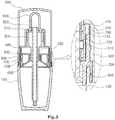
- FIG. 2is an exploded perspective view illustrating a configuration of a dropper-typed cosmetic container for mixed use of two different kinds of contents according to an exemplary embodiment of the present invention.
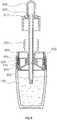
- FIG. 3is a cross-sectional view illustrating a configuration of a dropper-typed cosmetic container for mixed use of two different kinds of contents according to an exemplary embodiment of the present invention
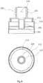
- FIGS. 4 and 5are views illustrating an assembled state of an inner cap, a rise and fall guide member, a content storage part, and a rotation guide member of a dropper-typed cosmetic container for mixed use of two different kinds of contents according to an exemplary embodiment of the present invention.
- FIG. 6is a view illustrating an outer cap of a dropper-typed cosmetic container for mixed use of two different kinds of contents according to an exemplary embodiment of the present invention.
- a dropper-typed cosmetic container for mixed use of two different kinds of contentsincludes a container body 100, an inner cap 200, an outer cap 300, a rise and fall guide member 400, a content storage part 500, a sealing member 600, a rotation guide member 700, and a dropping part 800.
- the container body 100contains a first content, and may include a coupling member formed at an upper portion thereof so as to enable coupling of the inner cap 200.
- the inner cap 200is coupled to the container body 100 while covering the upper portion of the container body 100.
- the inner cap 200has a cylindrical shape with an upper end and a lower end opened.
- the inner cap 200may include a seating step 210 formed at an inner side of the inner cap 200 and surrounding the inner circumferential surface such that the rise and fall guide member 400 and the rotation guide member 700 described later are seated the seating step 210.
- the inner cap 200may have a rotation preventing groove 220 formed at an upper portion thereof to allow a rotation preventing protrusion 710 to be inserted into the rotation preventing groove 220 at a portion where the inner cap 200 meets the rotation preventing protrusion 710 of the rotation guide member 700.
- the inner cap 200 and the rotation guide member 700may be configured to engage with each other, fixing the rotation guide member 700.
- the outer cap 300covers the inner cap 200 at an upper portion of the container body 100, and is rotatably coupled to the inner cap 300.
- the outer cap 300is coupled to the inner cap 200 while covering the inner cap 200, and may include a body 310 comprising a rotation indication part 311 formed on the outer circumferential surface of the body 310 so as to display the rotation direction, a dropper coupling part 320 upwardly extending from a central portion of the upper end of the body 310 and screw-coupled to the dropping part 800 described later, and a sealing member fixing part 330 downwardly extending from the central portion of the upper end of the body 310 and fixing the sealing member 600 described later.
- the body 310may have coupling grooves 312 formed at inner sides thereof to allow coupling protrusions 420 to be coupled to the coupling grooves 312 at portions where the body 310 meets the coupling protrusions 420 of the rise and fall guide member 400.
- the outer cap 300 and the rise and fall guide member 400may be configured to engage with each other, allowing the rise and fall guide member 400 to rotate together when the outer cap 300 rotates.
- the outer cap 300may have a hollow part 340 such that a dropper pipe 820 can be inserted into and withdrawn from the hollow part 340.
- the rise and fall guide member 400may be seated on the seating step 210 inside the inner cap 200, and may be formed to engage with the inner side of the outer cap 300 so as to rotate together when the outer cap 300 rotates.
- the rise and fall guide membermay include a plurality of coupling protrusions 420 formed on an upper portion of the outer circumferential surface thereof.
- the plurality of coupling protrusions 420may be spaced from each other at a uniform interval, and may be coupled to the coupling grooves 312 of the body so as to engage with the body 310.
- the rise and fall guide member 400has a pair of guide slits 410 opposite to each other at both side surfaces thereof.
- the guide slits 410guide the movement of a guide protrusion 510 of the content storage part 500 so as to the rising and falling of the content storage part 500.
- the content storage part 500is configured to rise and fall inside the rise and fall guide member 400 according to the rotation of the rise and fall guide member 400.
- the content storage part 500includes a pair of guide protrusions 510 formed at an upper portion of the outer circumferential surface thereof and coupled to the pair of the guide slits 410 so as to move along the guide slits 410.
- the inside of the content storage part 500may be spatially divided so as to contain a power or liquid type of a second content, and the lower end portion of the content storage part 500 may be opened.
- the lower end portion of the content storage part 500is closed by the sealing member 600 described later to block the second content from entering the container body 100.
- the opened lower end portion of the content storage part 500may become spaced from the sealing member 600, allowing the second content to drop to the container body 100.
- the content storage part 500may have a through hole 520 formed at the central portion of the upper end of the content storage part 500 such that the dropper pipe 820 can be inserted into or withdrawn from the content storage part 500.
- the sealing member 600closes the opened lower end portion of the content storage part 500, and may include a sealing plate 610 adhered closely to the inner circumferential surface of the lower end of the content storage part 500 to close the lower end of the content storage part 500 and a coupling tube 620 upwardly extending from the central portion of the top surface of the sealing plate 610 and coupled to a sealing member fixing part 330 of the outer cap 300.
- the rotation guide member 700is disposed to engage with the inner cap 200 between the inner cap 200 and the rise and fall guide member 400, and may include a plurality of rotation preventing protrusions 710 that are formed on upper portions of the outer circumferential surface and inserted into the rotation preventing grooves 220 so as to engage with the inner cap 200.
- the rotation preventing protrusion 710may be inserted into the rotation preventing groove 220 to fix the rotation guide member 700 to the inner cap 200. Thus, when the outer cap 300 and the rise and fall guide member 400 rotate, the rotation preventing protrusion 710 may not rotate, and may guide the movement of the guide protrusion 510 of the content storage part 500.
- the rotation guide member 700includes a screw thread 720 formed on the inner circumferential surface and guiding the movement of the guide protrusion 510.
- the rotation guide member 700may guide the rising and falling of the content storage part 500, by guiding the movement of the guide protrusion 510 through the screw thread 720.
- the dropping part 800is detachably coupled to the outer cap 300.
- the dropping part 800may be screw-coupled to the dropper coupling part 320 while covering the dropper coupling part 320, and may include a grip part 810 gripped by a user, a dropper pipe 820 downwardly extending from the center of the grip part 810 and having a tubular shape suctioning and discharging contents, and a rubber member 830 disposed at the upper end of the grip part 810, coupled to the upper portion of the dropper pipe 820 while covering the upper portion of the dropper pipe 820, and suctioning and discharging contents into/from the dropper pipe 820 by a pressurization of a user.
- the dropping part 800can allow a user to withdraw and use a fixed quantity of mixture of the first and second contents contained in the container body 100 through an manipulation of the rubber member 830.
- an over cap 900may be disposed over the outer cap 300 to prevent the dropping part 800 from malfunctioning and protect the rubber member 830 of the dropping part 800.
- the over cap 900may cover the dropping part 800.
- FIGS. 7 and 9are views illustrating an operation state of a dropper-typed cosmetic container for mixed use of two different kinds of contents according to an exemplary embodiment of the present invention.
- the opened lower end of the content storage part 500may be closed by the sealing member 600.
- the rise and fall guide member 400 engaged with the outer cap 300may rotate together, and thus the guide protrusion 510 may move along the guide slit 410.
- the screw thread 720 of the rotation guide member 700may guide the rising of the guide protrusion 510, and the content storage part 500 may rise according to the rising of the guide protrusion.
- the opened lower end of the content storage part 500may become spaced from the sealing member 600, and thus the second content contained in the content storage part 500 may drop down into the container body 100, allowing the first content and the second content to be mixed with each other.
- a usermay manipulate the rubber member 830 of the dropping part 800 to suction the mixture of the first and second contents into the dropper piper 820, and then may detach the dropping part 800 from the outer cap 300.
- a usermay manipulate the rubber member 830 of the dropping part 800 to suction the mixture of the first and second contents into the dropper piper 820, and then may detach the dropping part 800 from the outer cap 300.
- the dropper-typed cosmetic container for mixed use of two different kinds of contentscan simply mix two different kinds of contents and can withdraw a proper amount of the mixed contents for use with a dropping part, by raising a content storage part while a rise and fall guide member engaged with an outer cap rotates together upon rotation of the outer cap and thus opening a lower end portion of the content storage part closed by a sealing member to move the contents stored in the content storage part to a container body.
Landscapes
- Engineering & Computer Science (AREA)
- Mechanical Engineering (AREA)
- Health & Medical Sciences (AREA)
- Clinical Laboratory Science (AREA)
- Chemical & Material Sciences (AREA)
- Chemical Kinetics & Catalysis (AREA)
- Closures For Containers (AREA)
- Package Specialized In Special Use (AREA)
Description
- The present invention disclosed herein relates to a dropper-typed cosmetic container for mixed use of two different kinds of contents, and more particularly, to a dropper-typed cosmetic container for mixed use of two different kinds of contents, which can simply mix two different kinds of contents and can withdraw a proper amount of the mixed contents for use with a dropping part, by raising a content storage part while a rise and fall guide member engaged with an outer cap rotates together upon rotation of the outer cap and thus opening a lower end portion of the content storage part closed by a sealing member to move the contents stored in the content storage part to a container body.
- Generally, most containers that are being distributed and used store one kind of content for use.
- Recently, cases where a powder content is mixed with a liquid content or where different liquid contents are mixed with each other are increasing to improve the characteristics of the content. In this case, containers for storing two different kinds of contents need to be separately prepared. Accordingly, when two different kinds of contents are mixed with each other, there is an inconvenience in that two containers need to be dealt with.
- Also, due to separate packaging and manufacturing of containers for two contents, resources may be wasted. Furthermore, contents are arbitrarily mixed by a user instead of being accurately mixed. In this case, when food and beverage are mixed, the taste may be changed or spoiled, causing a chemical change. Also, when chemicals and chemical products are mixed with each other, a physical change action such as an incomplete dissolution of a material effect may occur.
- In order to overcome these limitations, various kinds of containers which store two different kinds of contents in one container and then mix the two different kinds of contents for use are being developed.
- The present invention provides a dropper-typed cosmetic container for mixed use of two different kinds of contents, which can simply mix two different kinds of contents and can withdraw a proper amount of the mixed contents for use with a dropping part, by raising a content storage part while a rise and fall guide member engaged with an outer cap rotates together upon rotation of the outer cap and thus opening a lower end portion of the content storage part closed by a sealing member to move the contents stored in the content storage part to a container body.
- Embodiments of the present invention provide dropper-typed cosmetic containers for mixed use of two different kinds of contents, comprising: a container body containing a first content; an inner cap having a cylindrical shape and coupled to the container body while covering an upper portion of the container body; an outer cap rotatably coupled to the inner cap over the container body while covering the inner cap and having a hollow part; a rise and fall guide member disposed inside the inner cap and engaging with an inner side of the outer cap so as to rotate together when the outer cap rotates, the rise and fall guide member having a pair of guide slits opposite to each other at both side surface thereof; a content storage part comprising a pair of guide protrusion each coupled to the pair of guide slits so as to rise and fall inside the rise and fall guide member according to the rotation of the rise and fall guide member and having a space for containing a second content, the content storage part having an lower end thereof opened; a sealing member closing the opened lower end of the content storage part; a rotation guide member disposed so as to engage with the inner cap between the inner cap and the rise and fall guide member and comprising a screw thread on an inner circumferential surface thereof to guide a movement of the guide protrusion; and a dropping part detachably coupled to the outer cap and withdrawing a fixed quantity of mixture of the first and second contents contained in the container body.
- In some embodiments, the inner cap may include a seating step surrounding an inner circumferential surface such that the rise and fall guide member and the rotation guide member are seated thereon.
- In other embodiments, the rotation guide member may include a plurality of rotation preventing protrusions formed on upper portions of an outer circumferential surface thereof and spaced from each other at a uniform interval so as to engage with the inner cap, and the inner cap may include a plurality of rotation preventing grooves formed at upper portions thereof such that the rotation preventing protrusions are inserted into portions meeting the rotation preventing protrusions.
- In still other embodiments, the outer cap may include: a body coupled to the inner cap while covering the inner cap and comprises a rotation indication part on an outer circumferential surface thereof to indicate a rotation direction of the outer cap; a dropper coupling part upwardly extending from a central portion of an upper end of the body and screw-coupled to the dropping part; and a sealing member fixing part downwardly extending from the central portion of the upper end of the body and fixing the sealing member.
- In even other embodiments, the rise and fall guide member may include a plurality of coupling protrusions formed on upper portions of an outer circumferential surface thereof and spaced from each other at a uniform interval so as to engage with the body of the outer cap, and the outer cap may have coupling grooves formed on an inner side of the body and coupled to the coupling protrusions at portions meeting the coupling protrusions.
- In yet other embodiments, the dropping part may include: a grip part screw-coupled to the dropper coupling part; a dropper pipe downwardly extending from a center of the grip part, suctioning and discharging the contents, and having a cylindrical shape; and a rubber member coupled to an upper portion of the dropper pipe while covering the upper portion of the dropper pipe and suctioning and discharging the contents into/from the dropper pipe by a pressurization of a user
- In further embodiments, the sealing member may include: a sealing plate adhered closely to an inner circumferential surface of a lower end of the content storage part to close the lower end of the content storage part; and a coupling tube upwardly extending from a central portion of a top surface of the sealing plate to be coupled to the sealing member fixing part of the outer cap.
- In still further embodiments, the content storage part may have a through hole at a central portion of an upper end thereof such that a dropper pipe is inserted into and withdrawn from the content storage part.
- The accompanying drawings are included to provide a further understanding of the present invention, and are incorporated in and constitute a part of this specification. The drawings illustrate exemplary embodiments of the present invention and, together with the description, serve to explain principles of the present invention. In the drawings:
FIG. 1 is a perspective view illustrating a configuration of a dropper-typed cosmetic container for mixed use of two different kinds of contents according to an exemplary embodiment of the present invention;FIG. 2 is an exploded perspective view illustrating a configuration of a dropper-typed cosmetic container for mixed use of two different kinds of contents according to an exemplary embodiment of the present invention;FIG. 3 is a cross-sectional view illustrating a configuration of a dropper-typed cosmetic container for mixed use of two different kinds of contents according to an exemplary embodiment of the present invention;FIGS. 4 and5 are views illustrating an assembled state of an inner cap, a rise and fall guide member, a content storage part, and a rotation guide member of a dropper-typed cosmetic container for mixed use of two different kinds of contents according to an exemplary embodiment of the present invention;FIG. 6 is a view illustrating an outer cap of a dropper-typed cosmetic container for mixed use of two different kinds of contents according to an exemplary embodiment of the present invention; andFIGS. 7 and9 are views illustrating a method of using a dropper-typed cosmetic container for mixed use of two different kinds of contents according to an exemplary embodiment of the present invention.- Preferred embodiments of the present invention will be described below in more detail with reference to the accompanying drawings. The present invention may, however, be embodied in different forms and should not be constructed as limited to the embodiments set forth herein. Rather, these embodiments are provided so that this disclosure will be thorough and complete, and will fully convey the scope of the present invention to those skilled in the art.
- Hereinafter, exemplary embodiments of the present invention will be described in detail with reference to the accompanying drawings. The same reference numerals provided in the drawings indicate the same members.
FIG. 1 is a perspective view illustrating a configuration of a dropper-typed cosmetic container for mixed use of two different kinds of contents according to an exemplary embodiment of the present invention.FIG. 2 is an exploded perspective view illustrating a configuration of a dropper-typed cosmetic container for mixed use of two different kinds of contents according to an exemplary embodiment of the present invention.FIG. 3 is a cross-sectional view illustrating a configuration of a dropper-typed cosmetic container for mixed use of two different kinds of contents according to an exemplary embodiment of the present inventionFIGS. 4 and5 are views illustrating an assembled state of an inner cap, a rise and fall guide member, a content storage part, and a rotation guide member of a dropper-typed cosmetic container for mixed use of two different kinds of contents according to an exemplary embodiment of the present invention.FIG. 6 is a view illustrating an outer cap of a dropper-typed cosmetic container for mixed use of two different kinds of contents according to an exemplary embodiment of the present invention.- Referring to
FIGS. 1 to 6 , a dropper-typed cosmetic container for mixed use of two different kinds of contents according to an exemplary embodiment of the present invention includes acontainer body 100, aninner cap 200, anouter cap 300, a rise andfall guide member 400, acontent storage part 500, asealing member 600, arotation guide member 700, and a droppingpart 800. - The
container body 100 contains a first content, and may include a coupling member formed at an upper portion thereof so as to enable coupling of theinner cap 200. - The
inner cap 200 is coupled to thecontainer body 100 while covering the upper portion of thecontainer body 100. Theinner cap 200 has a cylindrical shape with an upper end and a lower end opened. Theinner cap 200 may include aseating step 210 formed at an inner side of theinner cap 200 and surrounding the inner circumferential surface such that the rise andfall guide member 400 and therotation guide member 700 described later are seated theseating step 210. - In this embodiment, the
inner cap 200 may have arotation preventing groove 220 formed at an upper portion thereof to allow arotation preventing protrusion 710 to be inserted into therotation preventing groove 220 at a portion where theinner cap 200 meets therotation preventing protrusion 710 of therotation guide member 700. Through the coupling of therotation preventing groove 200 and therotation preventing protrusion 710, theinner cap 200 and therotation guide member 700 may be configured to engage with each other, fixing therotation guide member 700. - The
outer cap 300 covers theinner cap 200 at an upper portion of thecontainer body 100, and is rotatably coupled to theinner cap 300. Theouter cap 300 is coupled to theinner cap 200 while covering theinner cap 200, and may include abody 310 comprising arotation indication part 311 formed on the outer circumferential surface of thebody 310 so as to display the rotation direction, adropper coupling part 320 upwardly extending from a central portion of the upper end of thebody 310 and screw-coupled to the droppingpart 800 described later, and a sealingmember fixing part 330 downwardly extending from the central portion of the upper end of thebody 310 and fixing the sealingmember 600 described later. - In this embodiment, the
body 310 may havecoupling grooves 312 formed at inner sides thereof to allowcoupling protrusions 420 to be coupled to thecoupling grooves 312 at portions where thebody 310 meets thecoupling protrusions 420 of the rise andfall guide member 400. Through the coupling of thecoupling groove 312 and thecoupling protrusion 420, theouter cap 300 and the rise andfall guide member 400 may be configured to engage with each other, allowing the rise andfall guide member 400 to rotate together when theouter cap 300 rotates. - On the other hand, the
outer cap 300 may have ahollow part 340 such that adropper pipe 820 can be inserted into and withdrawn from thehollow part 340. - The rise and
fall guide member 400 may be seated on theseating step 210 inside theinner cap 200, and may be formed to engage with the inner side of theouter cap 300 so as to rotate together when theouter cap 300 rotates. The rise and fall guide member may include a plurality ofcoupling protrusions 420 formed on an upper portion of the outer circumferential surface thereof. The plurality ofcoupling protrusions 420 may be spaced from each other at a uniform interval, and may be coupled to thecoupling grooves 312 of the body so as to engage with thebody 310. - In this embodiment, the rise and
fall guide member 400 has a pair ofguide slits 410 opposite to each other at both side surfaces thereof. When the rise andfall guide member 400 rotates according to the rotation of theouter cap 300, the guide slits 410 guide the movement of aguide protrusion 510 of thecontent storage part 500 so as to the rising and falling of thecontent storage part 500. - The
content storage part 500 is configured to rise and fall inside the rise andfall guide member 400 according to the rotation of the rise andfall guide member 400. Thecontent storage part 500 includes a pair ofguide protrusions 510 formed at an upper portion of the outer circumferential surface thereof and coupled to the pair of theguide slits 410 so as to move along theguide slits 410. - The inside of the
content storage part 500 may be spatially divided so as to contain a power or liquid type of a second content, and the lower end portion of thecontent storage part 500 may be opened. The lower end portion of thecontent storage part 500 is closed by the sealingmember 600 described later to block the second content from entering thecontainer body 100. When thecontent storage part 500 rises, the opened lower end portion of thecontent storage part 500 may become spaced from the sealingmember 600, allowing the second content to drop to thecontainer body 100. - The
content storage part 500 may have a throughhole 520 formed at the central portion of the upper end of thecontent storage part 500 such that thedropper pipe 820 can be inserted into or withdrawn from thecontent storage part 500. - The sealing
member 600 closes the opened lower end portion of thecontent storage part 500, and may include a sealingplate 610 adhered closely to the inner circumferential surface of the lower end of thecontent storage part 500 to close the lower end of thecontent storage part 500 and acoupling tube 620 upwardly extending from the central portion of the top surface of the sealingplate 610 and coupled to a sealingmember fixing part 330 of theouter cap 300. - The
rotation guide member 700 is disposed to engage with theinner cap 200 between theinner cap 200 and the rise and fallguide member 400, and may include a plurality ofrotation preventing protrusions 710 that are formed on upper portions of the outer circumferential surface and inserted into therotation preventing grooves 220 so as to engage with theinner cap 200. - The
rotation preventing protrusion 710 may be inserted into therotation preventing groove 220 to fix therotation guide member 700 to theinner cap 200. Thus, when theouter cap 300 and the rise and fallguide member 400 rotate, therotation preventing protrusion 710 may not rotate, and may guide the movement of theguide protrusion 510 of thecontent storage part 500. Therotation guide member 700 includes ascrew thread 720 formed on the inner circumferential surface and guiding the movement of theguide protrusion 510. - The
rotation guide member 700 may guide the rising and falling of thecontent storage part 500, by guiding the movement of theguide protrusion 510 through thescrew thread 720. - The dropping
part 800 is detachably coupled to theouter cap 300. The droppingpart 800 may be screw-coupled to thedropper coupling part 320 while covering thedropper coupling part 320, and may include agrip part 810 gripped by a user, adropper pipe 820 downwardly extending from the center of thegrip part 810 and having a tubular shape suctioning and discharging contents, and arubber member 830 disposed at the upper end of thegrip part 810, coupled to the upper portion of thedropper pipe 820 while covering the upper portion of thedropper pipe 820, and suctioning and discharging contents into/from thedropper pipe 820 by a pressurization of a user. - When the second content stored in the
content storage part 500 moves into themain body 100 and thus the first and second contents are mixed with each other, the droppingpart 800 can allow a user to withdraw and use a fixed quantity of mixture of the first and second contents contained in thecontainer body 100 through an manipulation of therubber member 830. - Meanwhile, an over
cap 900 may be disposed over theouter cap 300 to prevent the droppingpart 800 from malfunctioning and protect therubber member 830 of the droppingpart 800. The overcap 900 may cover the droppingpart 800. - Hereinafter, an operation process of a dropper-typed cosmetic container for mixed use of two different kinds of contents according to an exemplary embodiment of the present invention will be described with reference to
FIGS. 7 and9 .FIGS. 7 and9 are views illustrating an operation state of a dropper-typed cosmetic container for mixed use of two different kinds of contents according to an exemplary embodiment of the present invention. - Referring to
FIGS. 7 and9 , in the dropper-typed cosmetic container for mixed use of two different kinds of contents according to an exemplary embodiment of the present invention, when theguide protrusion 510 of thecontent storage part 500 is located at the lower end of the guide slit 410, the opened lower end of thecontent storage part 500 may be closed by the sealingmember 600. When theouter cap 300 is rotated, the rise and fallguide member 400 engaged with theouter cap 300 may rotate together, and thus theguide protrusion 510 may move along the guide slit 410. In this case, thescrew thread 720 of therotation guide member 700 may guide the rising of theguide protrusion 510, and thecontent storage part 500 may rise according to the rising of the guide protrusion. Thus, the opened lower end of thecontent storage part 500 may become spaced from the sealingmember 600, and thus the second content contained in thecontent storage part 500 may drop down into thecontainer body 100, allowing the first content and the second content to be mixed with each other. - As described above, when the mixing of the first and second contents is completed, a user may manipulate the
rubber member 830 of the droppingpart 800 to suction the mixture of the first and second contents into thedropper piper 820, and then may detach the droppingpart 800 from theouter cap 300. Thus, it is possible to withdraw and use a fixed quantity of the mixed contents. - As described above, the dropper-typed cosmetic container for mixed use of two different kinds of contents can simply mix two different kinds of contents and can withdraw a proper amount of the mixed contents for use with a dropping part, by raising a content storage part while a rise and fall guide member engaged with an outer cap rotates together upon rotation of the outer cap and thus opening a lower end portion of the content storage part closed by a sealing member to move the contents stored in the content storage part to a container body.
- The above-disclosed subject matter is to be considered illustrative and not restrictive, and the appended claims are intended to cover all such modifications, enhancements, and other embodiments, which fall within the scope of the present invention. Thus, to the maximum extent allowed by law, the scope of the present invention is to be determined by the broadest permissible interpretation of the following claims, and shall not be restricted or limited by the foregoing detailed description.
Claims (8)
- A dropper-typed cosmetic container for mixed use of two different kinds of contents, comprising:a container body (100) containing a first content;an inner cap (200) having a cylindrical shape and coupled to the container body (100) while covering an upper portion of the container body (100);an outer cap (300) rotatably coupled to the inner cap (200) over the container body (100) while covering the inner cap (200) and having a hollow part;a rise and fall guide member (400) disposed inside the inner cap (200) and engaging with an inner side of the outer cap (300) so as to rotate together when the outer cap (300) rotates, the rise and fall guide member (400) having a pair of guide slits (410) opposite to each other at both side surface thereof;a content storage part (500) comprising a pair of guide protrusion (510) each coupled to the pair of guide slits (410) so as to rise and fall inside the rise and fall guide member (400) according to the rotation of the rise and fall guide member (400) and having a space for containing a second content, the content storage part (500) having an lower end thereof opened;a sealing member (600) closing the opened lower end of the content storage part (500);a rotation guide member (700) disposed so as to engage with the inner cap (200) between the inner cap (200) and the rise and fall guide member (400) and comprising a screw thread (720) on an inner circumferential surface thereof to guide a movement of the guide protrusion (510); anda dropping part (800) detachably coupled to the outer cap (300) and withdrawing a fixed quantity of mixture of the first and second contents contained in the container body.
- The dropper-typed cosmetic container of claim 1, wherein the inner cap (200) comprises a seating step (210) surrounding an inner circumferential surface such that the rise and fall guide member (400) and the rotation guide member (700) are seated thereon.
- The dropper-typed cosmetic container of claim 1, wherein the rotation guide member (700) a plurality of rotation preventing protrusions (710) on upper portions of an outer circumferential surface thereof and spaced from each other at a uniform interval so as to engage with the inner cap (200), and the inner cap (200) comprises a plurality of rotation preventing grooves (220) formed at upper portions thereof such that the rotation preventing protrusions (710) are inserted into the rotation preventing grooves (220).
- The dropper-type cosmetic container of claim 1, wherein the outer cap (300) comprises:a body (310) coupled to the inner cap (200) while covering the inner cap (200) and comprises a rotation indication part (311) on an outer circumferential surface thereof to indicate a rotation direction of the outer cap;a dropper coupling part (320) upwardly extending from a central portion of an upper end of the body and screw-coupled to the dropping part (800); anda sealing member fixing part (330) downwardly extending from the central portion of the upper end of the body (310) and fixing the sealing member (600).
- The dropper-type cosmetic container of claim 4, wherein the rise and fall guide member (400) comprises a plurality of coupling protrusions (420) formed on upper portions of an outer circumferential surface thereof and spaced from each other at a uniform interval so as to engage with the body (310) of the outer cap (300), and the outer cap (300) has coupling grooves (312) formed on an inner side of the body (310) and coupled to the coupling protrusions (420) at portions meeting the coupling protrusions (420).
- The dropper-type cosmetic container of claim 4, wherein the dropping part (800) comprises:a grip part (810) screw-coupled to the dropper coupling part (320);a dropper pipe (820) downwardly extending from a center of the grip part (810), suctioning and discharging the contents, and having a cylindrical shape; anda rubber member (830) coupled to an upper portion of the dropper pipe (820) while covering the upper portion of the dropper pipe (820) and suctioning and discharging the contents into/from the dropper pipe (820) by a pressurization of a user.
- The dropper-type cosmetic container of claim 4, wherein the sealing member (600) comprises:a sealing plate (610) adhered closely to an inner circumferential surface of a lower end of the content storage part (500) to close the lower end of the content storage part (500); anda coupling tube (620) upwardly extending from a central portion of a top surface of the sealing plate (610) to be coupled to the sealing member fixing part (330) of the outer cap (300).
- The dropper-type cosmetic container of claim 1, wherein the content storage part (500) has a through hole (520) at a central portion of an upper end thereof such that a dropper pipe (820), downwardly extending from the center of the grip part (810), is inserted into and withdrawn from the content storage part (500)
Applications Claiming Priority (2)
| Application Number | Priority Date | Filing Date | Title |
|---|---|---|---|
| KR1020120035772AKR101370284B1 (en) | 2012-04-06 | 2012-04-06 | Spuit type Cosmetic vessel having mixed two-type materials |
| PCT/KR2013/001922WO2013151244A1 (en) | 2012-04-06 | 2013-03-11 | Dropper-type cosmetics container in which different types of contents can be used in mixed manner |
Publications (3)
| Publication Number | Publication Date |
|---|---|
| EP2835075A1 EP2835075A1 (en) | 2015-02-11 |
| EP2835075A4 EP2835075A4 (en) | 2016-01-27 |
| EP2835075B1true EP2835075B1 (en) | 2017-05-10 |
Family
ID=49300694
Family Applications (1)
| Application Number | Title | Priority Date | Filing Date |
|---|---|---|---|
| EP13773063.6AActiveEP2835075B1 (en) | 2012-04-06 | 2013-03-11 | Dropper-type cosmetics container in which different types of contents can be used in mixed manner |
Country Status (7)
| Country | Link |
|---|---|
| US (1) | US9351556B2 (en) |
| EP (1) | EP2835075B1 (en) |
| JP (1) | JP6145949B2 (en) |
| KR (1) | KR101370284B1 (en) |
| CN (1) | CN104203039B (en) |
| ES (1) | ES2636923T3 (en) |
| WO (1) | WO2013151244A1 (en) |
Families Citing this family (50)
| Publication number | Priority date | Publication date | Assignee | Title |
|---|---|---|---|---|
| KR200453126Y1 (en)* | 2010-07-23 | 2011-04-13 | 주식회사 에프에스코리아 | Eyedropper Cosmetic Container |
| KR101491383B1 (en) | 2013-12-06 | 2015-02-23 | 최종서 | Structure of cap for vessel |
| US9643760B2 (en)* | 2013-11-20 | 2017-05-09 | Jong-Suh Choi | Cap structure for vessel |
| KR101503239B1 (en)* | 2014-09-25 | 2015-03-18 | (주)연우 | The container containing different kinds of contents |
| KR200487631Y1 (en)* | 2014-11-05 | 2018-10-16 | (주)아모레퍼시픽 | Spuit typed mixing container for tow liquid |
| KR101660033B1 (en)* | 2015-03-30 | 2016-09-26 | (주)연우 | Cosmetic vessel having mixed two-type materials |
| KR101619957B1 (en)* | 2015-04-10 | 2016-05-12 | (주)연우 | Cosmetic vessel having mixed two-type materials |
| KR101533095B1 (en)* | 2015-04-24 | 2015-07-10 | (주)연우 | Tube vessel with a applicator |
| KR101688618B1 (en)* | 2015-05-13 | 2016-12-21 | (주)연우 | Cosmetic vessel having mixed two-type materials |
| KR20170042019A (en)* | 2015-10-08 | 2017-04-18 | 강성일 | A Mixing Container for Two Liquid Type Solution |
| CN108697221B (en)* | 2016-01-25 | 2021-05-14 | 欧莱雅 | Filling assembly for manufacturing a dual content packaging and dispensing device |
| FR3053222A1 (en)* | 2016-06-30 | 2018-01-05 | L'oreal | SYSTEM FOR CONDITIONING AND DISPENSING A FLUID PRODUCT, IN PARTICULAR A COSMETIC FLUID PRODUCT |
| JP6342958B2 (en)* | 2016-08-17 | 2018-06-13 | アモーレパシフィック コーポレーション | Syringe container with flock tip with temporary storage |
| WO2018062971A1 (en)* | 2016-09-30 | 2018-04-05 | (주)아모레퍼시픽 | Device for preparing cosmetic composition containing multiple formulation instantly emulsified based on microfluidic channel |
| KR101789573B1 (en)* | 2016-12-29 | 2017-10-25 | (주)연우 | Spuit type cosmetics container |
| CN106516441B (en)* | 2016-12-29 | 2019-09-06 | 青海纳瑞亚生物科技有限公司 | A kind of difference states of matter separate type fusion bottle |
| USD886386S1 (en)* | 2017-02-28 | 2020-06-02 | Go Products Co. | Lip balm applicator |
| USD884282S1 (en)* | 2017-08-30 | 2020-05-12 | Yonwoo Co., Ltd. | Cosmetic container |
| KR101912587B1 (en)* | 2017-09-14 | 2018-10-30 | 펌텍코리아(주) | Spuit type container having mixed two-type material |
| KR102020455B1 (en)* | 2018-02-14 | 2019-09-11 | 펌텍코리아(주) | Spuit type cosmetic container having adjustable down distance push botton |
| KR101883730B1 (en) | 2018-05-24 | 2018-07-31 | 주식회사 네스필러피케이지 | Cosmetic vessel having mixed two-type materials |
| KR101884287B1 (en) | 2018-06-18 | 2018-08-01 | 주식회사 네스필러피케이지 | Cosmetic vessel having mixed two-type materials |
| KR102199520B1 (en)* | 2018-07-09 | 2021-01-07 | 코스맥스 주식회사 | Cosmetic container |
| KR102085874B1 (en)* | 2018-07-19 | 2020-03-06 | (주)아모레퍼시픽 | A Vessel having mixed two-type materials |
| US11382400B2 (en) | 2018-08-10 | 2022-07-12 | Go Products Co. | Material applicator |
| KR200498672Y1 (en)* | 2018-11-23 | 2024-12-31 | 브리바플라스트 에스.알.엘. | Container for liquid or paste products |
| USD928618S1 (en)* | 2018-12-13 | 2021-08-24 | Shinsegae International Inc. | Container for cosmetics |
| KR102252534B1 (en)* | 2018-12-14 | 2021-05-14 | (주)아모레퍼시픽 | Main container for mixing cosmetic and sub container for mixing cosmetic and cosmetic including same |
| KR102164829B1 (en) | 2018-12-31 | 2020-10-13 | (주)아모레퍼시픽 | Portable apparatus for manufacturing cosmetic |
| KR102161515B1 (en)* | 2019-02-26 | 2020-10-05 | 코스맥스 주식회사 | Cosmetic case |
| KR102104203B1 (en)* | 2019-03-19 | 2020-04-23 | 주식회사 삼화 | Possible use of a mixture of cosmetic containers |
| JP7229639B2 (en)* | 2019-03-29 | 2023-02-28 | 株式会社吉野工業所 | discharge container |
| KR102188198B1 (en)* | 2019-04-15 | 2020-12-11 | 주식회사 삼화 | Container for mixing different kinds of contents |
| KR102035519B1 (en) | 2019-04-24 | 2019-10-23 | (주)네스필러피케이지 | Cosmetic vessel having mixed two-type materials |
| KR102226973B1 (en)* | 2019-05-07 | 2021-03-15 | 주식회사 삼화 | Mixing container having spuid |
| KR102197420B1 (en)* | 2019-05-17 | 2021-01-04 | 펌텍코리아(주) | Spuit type heterogeneous contents mixing container |
| CN110589213B (en)* | 2019-09-26 | 2024-09-17 | 富祥塑胶制品(上海)有限公司 | Dropper device |
| US12037166B2 (en)* | 2019-10-14 | 2024-07-16 | F.S.Korea Industries Inc. | Integrated cosmetic dropper |
| KR20230051546A (en)* | 2020-08-17 | 2023-04-18 | 로레알 | Cosmetic packaging and dispensing device comprising a bottle and at least one cartridge |
| KR102442863B1 (en)* | 2020-11-20 | 2022-09-14 | (주)연우 | Container |
| USD1021262S1 (en)* | 2020-11-27 | 2024-04-02 | L'oreal | Cosmetic bottle |
| CN112790502B (en)* | 2021-01-27 | 2024-10-22 | 上海英宇包装科技有限公司 | Double-material mixed cosmetic dropper bottle |
| CN112826205B (en)* | 2021-01-27 | 2024-09-24 | 上海英宇包装科技有限公司 | Double-material mixed cosmetic dropper bottle |
| CN115123669B (en)* | 2021-03-26 | 2025-08-19 | 西尔格定量泵(无锡)有限公司 | Lid subassembly reaches burette subassembly and container system including it |
| USD1001640S1 (en)* | 2021-06-11 | 2023-10-17 | Netmarble Healer.B Co., Ltd. | Cosmetics container |
| CN113455801B (en)* | 2021-07-20 | 2023-08-29 | 广东圣威玻璃科技有限公司 | Cosmetic packaging bottle convenient to absorb and thoroughly clean to use |
| KR20230079759A (en)* | 2021-11-29 | 2023-06-07 | (주)연우 | Container |
| USD1014098S1 (en)* | 2023-04-08 | 2024-02-13 | Peng Wei | Brush head |
| KR102740956B1 (en)* | 2023-05-18 | 2024-12-10 | 주식회사 삼화 | Two-in-one cosmetic container for brush-applied cosmetics |
| KR20250045971A (en) | 2023-09-26 | 2025-04-02 | (주)아모레퍼시픽 | Microfluidic chip |
Family Cites Families (14)
| Publication number | Priority date | Publication date | Assignee | Title |
|---|---|---|---|---|
| IT1185850B (en)* | 1985-08-02 | 1987-11-18 | Zambon Spa | DROP TANK CAP FOR BOTTLES |
| JPH02129080U (en)* | 1989-03-30 | 1990-10-24 | ||
| US5217433A (en)* | 1991-05-24 | 1993-06-08 | Merck & Co., Inc. | Medication container for mixing two components |
| JP2549350Y2 (en)* | 1993-10-15 | 1997-09-30 | 鐘紡株式会社 | Dropper container |
| US6290100B1 (en)* | 2000-06-30 | 2001-09-18 | Canberra Corporation | Concentrate cartridge for a diluting and dispensing container |
| KR200256383Y1 (en) | 2001-09-19 | 2001-12-14 | 송감섭 | A case cam use separayion charge and mix to powder or solution of different each otater ponenit |
| KR200270335Y1 (en)* | 2001-10-10 | 2002-04-03 | 조휘철 | A vessel for container the cosmetic differ in kind |
| KR200266847Y1 (en)* | 2001-12-05 | 2002-03-04 | (주)연우 | dispenser |
| KR200348004Y1 (en) | 2003-12-11 | 2004-04-28 | 주식회사 씨디알 | A dressing case filled up a different kind materials |
| KR200407438Y1 (en)* | 2005-11-18 | 2006-01-31 | 강성일 | Easy to mix contents |
| FR2911329B1 (en)* | 2007-01-12 | 2009-04-17 | Rexam Pharma Soc Par Actions S | PACKAGING AND DISPENSING ASSEMBLY OF A MEDICAL LIQUID |
| WO2011019217A2 (en)* | 2009-08-12 | 2011-02-17 | (주)연우 | Cosmetic container capable of mixed use of different kinds of contents |
| KR20110016832A (en)* | 2009-08-12 | 2011-02-18 | (주)연우 | Cosmetic container that can mix and use different contents |
| FR2973782B1 (en)* | 2011-04-07 | 2013-06-21 | Valois Sas | DISPENSER DROPPER. |
- 2012
- 2012-04-06KRKR1020120035772Apatent/KR101370284B1/enactiveActive
- 2013
- 2013-03-11USUS14/390,878patent/US9351556B2/enactiveActive
- 2013-03-11EPEP13773063.6Apatent/EP2835075B1/enactiveActive
- 2013-03-11WOPCT/KR2013/001922patent/WO2013151244A1/enactiveApplication Filing
- 2013-03-11ESES13773063.6Tpatent/ES2636923T3/enactiveActive
- 2013-03-11CNCN201380018890.2Apatent/CN104203039B/enactiveActive
- 2013-03-11JPJP2015504476Apatent/JP6145949B2/enactiveActive
Also Published As
| Publication number | Publication date |
|---|---|
| KR101370284B1 (en) | 2014-03-05 |
| ES2636923T3 (en) | 2017-10-10 |
| CN104203039A (en) | 2014-12-10 |
| US20150059923A1 (en) | 2015-03-05 |
| JP2015516200A (en) | 2015-06-11 |
| CN104203039B (en) | 2016-12-14 |
| EP2835075A1 (en) | 2015-02-11 |
| US9351556B2 (en) | 2016-05-31 |
| KR20130113548A (en) | 2013-10-16 |
| JP6145949B2 (en) | 2017-06-14 |
| EP2835075A4 (en) | 2016-01-27 |
| WO2013151244A1 (en) | 2013-10-10 |
Similar Documents
| Publication | Publication Date | Title |
|---|---|---|
| EP2835075B1 (en) | Dropper-type cosmetics container in which different types of contents can be used in mixed manner | |
| RU2582467C2 (en) | Hand-held mixing vessel | |
| US6935493B2 (en) | Cap device for mixing different kinds of materials separately contained therein and in bottle | |
| US8584840B2 (en) | Device and method for storing and dispensing | |
| KR100593246B1 (en) | Bottle | |
| US20090178940A1 (en) | Stacked-container reusable bottle, system and method providing flexible use and mixing | |
| EP2862814B1 (en) | Container capable of mixing multiple materials | |
| US9033603B2 (en) | Container with improved opening system | |
| JP2016531056A (en) | Contents receiving device, opening / closing mechanism and packaging container provided with the same | |
| US20120223100A1 (en) | Bottle cap for dispersing powdered supplement in situ | |
| US20130239821A1 (en) | Container with Removable Bottom Tea Infuser | |
| US20170225832A1 (en) | Retainable scoop and container | |
| WO2010004252A2 (en) | Closure element a fluid container | |
| US9909915B2 (en) | Dispenser | |
| KR101444020B1 (en) | Container spigot for button system | |
| KR200485603Y1 (en) | Container for mixing liquid | |
| KR20150106289A (en) | Discharge device of required dose and packing container having the discharge device | |
| KR101635471B1 (en) | Discharging device having different material | |
| KR101398750B1 (en) | Cap for the mixing of additives | |
| KR101311199B1 (en) | A Vessel having mixed two-type materials | |
| US20170050783A1 (en) | Storing and mixing device | |
| KR20170099652A (en) | Bottle Closure For Providing Contents and Bottle Assembly With The Same | |
| CN107912034B (en) | mixer stopper | |
| KR20160023520A (en) | Contents receiving device | |
| KR20200000863U (en) | bottle with opening device |
Legal Events
| Date | Code | Title | Description |
|---|---|---|---|
| PUAI | Public reference made under article 153(3) epc to a published international application that has entered the european phase | Free format text:ORIGINAL CODE: 0009012 | |
| 17P | Request for examination filed | Effective date:20141028 | |
| AK | Designated contracting states | Kind code of ref document:A1 Designated state(s):AL AT BE BG CH CY CZ DE DK EE ES FI FR GB GR HR HU IE IS IT LI LT LU LV MC MK MT NL NO PL PT RO RS SE SI SK SM TR | |
| AX | Request for extension of the european patent | Extension state:BA ME | |
| DAX | Request for extension of the european patent (deleted) | ||
| RA4 | Supplementary search report drawn up and despatched (corrected) | Effective date:20160105 | |
| RIC1 | Information provided on ipc code assigned before grant | Ipc:B65D 81/32 20060101ALI20151221BHEP Ipc:A45D 34/00 20060101AFI20151221BHEP Ipc:B01L 3/02 20060101ALI20151221BHEP Ipc:B65D 51/32 20060101ALI20151221BHEP | |
| GRAP | Despatch of communication of intention to grant a patent | Free format text:ORIGINAL CODE: EPIDOSNIGR1 | |
| INTG | Intention to grant announced | Effective date:20161026 | |
| GRAS | Grant fee paid | Free format text:ORIGINAL CODE: EPIDOSNIGR3 | |
| STAA | Information on the status of an ep patent application or granted ep patent | Free format text:STATUS: GRANT OF PATENT IS INTENDED | |
| GRAA | (expected) grant | Free format text:ORIGINAL CODE: 0009210 | |
| STAA | Information on the status of an ep patent application or granted ep patent | Free format text:STATUS: THE PATENT HAS BEEN GRANTED | |
| AK | Designated contracting states | Kind code of ref document:B1 Designated state(s):AL AT BE BG CH CY CZ DE DK EE ES FI FR GB GR HR HU IE IS IT LI LT LU LV MC MK MT NL NO PL PT RO RS SE SI SK SM TR | |
| REG | Reference to a national code | Ref country code:GB Ref legal event code:FG4D | |
| REG | Reference to a national code | Ref country code:AT Ref legal event code:REF Ref document number:891384 Country of ref document:AT Kind code of ref document:T Effective date:20170515 Ref country code:CH Ref legal event code:EP | |
| REG | Reference to a national code | Ref country code:IE Ref legal event code:FG4D | |
| REG | Reference to a national code | Ref country code:DE Ref legal event code:R096 Ref document number:602013021009 Country of ref document:DE | |
| REG | Reference to a national code | Ref country code:NL Ref legal event code:MP Effective date:20170510 | |
| REG | Reference to a national code | Ref country code:LT Ref legal event code:MG4D | |
| REG | Reference to a national code | Ref country code:ES Ref legal event code:FG2A Ref document number:2636923 Country of ref document:ES Kind code of ref document:T3 Effective date:20171010 | |
| REG | Reference to a national code | Ref country code:AT Ref legal event code:MK05 Ref document number:891384 Country of ref document:AT Kind code of ref document:T Effective date:20170510 | |
| PG25 | Lapsed in a contracting state [announced via postgrant information from national office to epo] | Ref country code:GR Free format text:LAPSE BECAUSE OF FAILURE TO SUBMIT A TRANSLATION OF THE DESCRIPTION OR TO PAY THE FEE WITHIN THE PRESCRIBED TIME-LIMIT Effective date:20170811 Ref country code:AT Free format text:LAPSE BECAUSE OF FAILURE TO SUBMIT A TRANSLATION OF THE DESCRIPTION OR TO PAY THE FEE WITHIN THE PRESCRIBED TIME-LIMIT Effective date:20170510 Ref country code:FI Free format text:LAPSE BECAUSE OF FAILURE TO SUBMIT A TRANSLATION OF THE DESCRIPTION OR TO PAY THE FEE WITHIN THE PRESCRIBED TIME-LIMIT Effective date:20170510 Ref country code:LT Free format text:LAPSE BECAUSE OF FAILURE TO SUBMIT A TRANSLATION OF THE DESCRIPTION OR TO PAY THE FEE WITHIN THE PRESCRIBED TIME-LIMIT Effective date:20170510 Ref country code:NO Free format text:LAPSE BECAUSE OF FAILURE TO SUBMIT A TRANSLATION OF THE DESCRIPTION OR TO PAY THE FEE WITHIN THE PRESCRIBED TIME-LIMIT Effective date:20170810 Ref country code:HR Free format text:LAPSE BECAUSE OF FAILURE TO SUBMIT A TRANSLATION OF THE DESCRIPTION OR TO PAY THE FEE WITHIN THE PRESCRIBED TIME-LIMIT Effective date:20170510 | |
| PG25 | Lapsed in a contracting state [announced via postgrant information from national office to epo] | Ref country code:SE Free format text:LAPSE BECAUSE OF FAILURE TO SUBMIT A TRANSLATION OF THE DESCRIPTION OR TO PAY THE FEE WITHIN THE PRESCRIBED TIME-LIMIT Effective date:20170510 Ref country code:PL Free format text:LAPSE BECAUSE OF FAILURE TO SUBMIT A TRANSLATION OF THE DESCRIPTION OR TO PAY THE FEE WITHIN THE PRESCRIBED TIME-LIMIT Effective date:20170510 Ref country code:RS Free format text:LAPSE BECAUSE OF FAILURE TO SUBMIT A TRANSLATION OF THE DESCRIPTION OR TO PAY THE FEE WITHIN THE PRESCRIBED TIME-LIMIT Effective date:20170510 Ref country code:NL Free format text:LAPSE BECAUSE OF FAILURE TO SUBMIT A TRANSLATION OF THE DESCRIPTION OR TO PAY THE FEE WITHIN THE PRESCRIBED TIME-LIMIT Effective date:20170510 Ref country code:IS Free format text:LAPSE BECAUSE OF FAILURE TO SUBMIT A TRANSLATION OF THE DESCRIPTION OR TO PAY THE FEE WITHIN THE PRESCRIBED TIME-LIMIT Effective date:20170910 Ref country code:LV Free format text:LAPSE BECAUSE OF FAILURE TO SUBMIT A TRANSLATION OF THE DESCRIPTION OR TO PAY THE FEE WITHIN THE PRESCRIBED TIME-LIMIT Effective date:20170510 Ref country code:BG Free format text:LAPSE BECAUSE OF FAILURE TO SUBMIT A TRANSLATION OF THE DESCRIPTION OR TO PAY THE FEE WITHIN THE PRESCRIBED TIME-LIMIT Effective date:20170810 | |
| PG25 | Lapsed in a contracting state [announced via postgrant information from national office to epo] | Ref country code:CZ Free format text:LAPSE BECAUSE OF FAILURE TO SUBMIT A TRANSLATION OF THE DESCRIPTION OR TO PAY THE FEE WITHIN THE PRESCRIBED TIME-LIMIT Effective date:20170510 Ref country code:DK Free format text:LAPSE BECAUSE OF FAILURE TO SUBMIT A TRANSLATION OF THE DESCRIPTION OR TO PAY THE FEE WITHIN THE PRESCRIBED TIME-LIMIT Effective date:20170510 Ref country code:SK Free format text:LAPSE BECAUSE OF FAILURE TO SUBMIT A TRANSLATION OF THE DESCRIPTION OR TO PAY THE FEE WITHIN THE PRESCRIBED TIME-LIMIT Effective date:20170510 Ref country code:RO Free format text:LAPSE BECAUSE OF FAILURE TO SUBMIT A TRANSLATION OF THE DESCRIPTION OR TO PAY THE FEE WITHIN THE PRESCRIBED TIME-LIMIT Effective date:20170510 Ref country code:EE Free format text:LAPSE BECAUSE OF FAILURE TO SUBMIT A TRANSLATION OF THE DESCRIPTION OR TO PAY THE FEE WITHIN THE PRESCRIBED TIME-LIMIT Effective date:20170510 | |
| REG | Reference to a national code | Ref country code:DE Ref legal event code:R097 Ref document number:602013021009 Country of ref document:DE | |
| PG25 | Lapsed in a contracting state [announced via postgrant information from national office to epo] | Ref country code:SM Free format text:LAPSE BECAUSE OF FAILURE TO SUBMIT A TRANSLATION OF THE DESCRIPTION OR TO PAY THE FEE WITHIN THE PRESCRIBED TIME-LIMIT Effective date:20170510 Ref country code:IT Free format text:LAPSE BECAUSE OF FAILURE TO SUBMIT A TRANSLATION OF THE DESCRIPTION OR TO PAY THE FEE WITHIN THE PRESCRIBED TIME-LIMIT Effective date:20170510 | |
| PLBE | No opposition filed within time limit | Free format text:ORIGINAL CODE: 0009261 | |
| STAA | Information on the status of an ep patent application or granted ep patent | Free format text:STATUS: NO OPPOSITION FILED WITHIN TIME LIMIT | |
| REG | Reference to a national code | Ref country code:FR Ref legal event code:PLFP Year of fee payment:6 | |
| 26N | No opposition filed | Effective date:20180213 | |
| PG25 | Lapsed in a contracting state [announced via postgrant information from national office to epo] | Ref country code:SI Free format text:LAPSE BECAUSE OF FAILURE TO SUBMIT A TRANSLATION OF THE DESCRIPTION OR TO PAY THE FEE WITHIN THE PRESCRIBED TIME-LIMIT Effective date:20170510 | |
| REG | Reference to a national code | Ref country code:CH Ref legal event code:PL | |
| PG25 | Lapsed in a contracting state [announced via postgrant information from national office to epo] | Ref country code:MC Free format text:LAPSE BECAUSE OF FAILURE TO SUBMIT A TRANSLATION OF THE DESCRIPTION OR TO PAY THE FEE WITHIN THE PRESCRIBED TIME-LIMIT Effective date:20170510 | |
| REG | Reference to a national code | Ref country code:BE Ref legal event code:MM Effective date:20180331 | |
| REG | Reference to a national code | Ref country code:IE Ref legal event code:MM4A | |
| PG25 | Lapsed in a contracting state [announced via postgrant information from national office to epo] | Ref country code:LU Free format text:LAPSE BECAUSE OF NON-PAYMENT OF DUE FEES Effective date:20180311 | |
| PG25 | Lapsed in a contracting state [announced via postgrant information from national office to epo] | Ref country code:IE Free format text:LAPSE BECAUSE OF NON-PAYMENT OF DUE FEES Effective date:20180311 | |
| PG25 | Lapsed in a contracting state [announced via postgrant information from national office to epo] | Ref country code:BE Free format text:LAPSE BECAUSE OF NON-PAYMENT OF DUE FEES Effective date:20180331 Ref country code:CH Free format text:LAPSE BECAUSE OF NON-PAYMENT OF DUE FEES Effective date:20180331 Ref country code:LI Free format text:LAPSE BECAUSE OF NON-PAYMENT OF DUE FEES Effective date:20180331 | |
| PG25 | Lapsed in a contracting state [announced via postgrant information from national office to epo] | Ref country code:MT Free format text:LAPSE BECAUSE OF NON-PAYMENT OF DUE FEES Effective date:20180311 | |
| PG25 | Lapsed in a contracting state [announced via postgrant information from national office to epo] | Ref country code:TR Free format text:LAPSE BECAUSE OF FAILURE TO SUBMIT A TRANSLATION OF THE DESCRIPTION OR TO PAY THE FEE WITHIN THE PRESCRIBED TIME-LIMIT Effective date:20170510 | |
| PG25 | Lapsed in a contracting state [announced via postgrant information from national office to epo] | Ref country code:PT Free format text:LAPSE BECAUSE OF FAILURE TO SUBMIT A TRANSLATION OF THE DESCRIPTION OR TO PAY THE FEE WITHIN THE PRESCRIBED TIME-LIMIT Effective date:20170510 | |
| PG25 | Lapsed in a contracting state [announced via postgrant information from national office to epo] | Ref country code:MK Free format text:LAPSE BECAUSE OF NON-PAYMENT OF DUE FEES Effective date:20170510 Ref country code:CY Free format text:LAPSE BECAUSE OF FAILURE TO SUBMIT A TRANSLATION OF THE DESCRIPTION OR TO PAY THE FEE WITHIN THE PRESCRIBED TIME-LIMIT Effective date:20170510 Ref country code:HU Free format text:LAPSE BECAUSE OF FAILURE TO SUBMIT A TRANSLATION OF THE DESCRIPTION OR TO PAY THE FEE WITHIN THE PRESCRIBED TIME-LIMIT; INVALID AB INITIO Effective date:20130311 | |
| PG25 | Lapsed in a contracting state [announced via postgrant information from national office to epo] | Ref country code:AL Free format text:LAPSE BECAUSE OF FAILURE TO SUBMIT A TRANSLATION OF THE DESCRIPTION OR TO PAY THE FEE WITHIN THE PRESCRIBED TIME-LIMIT Effective date:20170510 | |
| PGFP | Annual fee paid to national office [announced via postgrant information from national office to epo] | Ref country code:FR Payment date:20241231 Year of fee payment:13 | |
| PGFP | Annual fee paid to national office [announced via postgrant information from national office to epo] | Ref country code:DE Payment date:20241231 Year of fee payment:13 | |
| PGFP | Annual fee paid to national office [announced via postgrant information from national office to epo] | Ref country code:GB Payment date:20250102 Year of fee payment:13 | |
| PGFP | Annual fee paid to national office [announced via postgrant information from national office to epo] | Ref country code:ES Payment date:20250411 Year of fee payment:13 |