EP2834556B1 - Multi-lens led-array optic system - Google Patents
Multi-lens led-array optic systemDownload PDFInfo
- Publication number
- EP2834556B1 EP2834556B1EP13772520.6AEP13772520AEP2834556B1EP 2834556 B1EP2834556 B1EP 2834556B1EP 13772520 AEP13772520 AEP 13772520AEP 2834556 B1EP2834556 B1EP 2834556B1
- Authority
- EP
- European Patent Office
- Prior art keywords
- lens
- led
- lighting apparatus
- light
- array
- Prior art date
- Legal status (The legal status is an assumption and is not a legal conclusion. Google has not performed a legal analysis and makes no representation as to the accuracy of the status listed.)
- Active
Links
Images


Classifications
- F—MECHANICAL ENGINEERING; LIGHTING; HEATING; WEAPONS; BLASTING
- F21—LIGHTING
- F21V—FUNCTIONAL FEATURES OR DETAILS OF LIGHTING DEVICES OR SYSTEMS THEREOF; STRUCTURAL COMBINATIONS OF LIGHTING DEVICES WITH OTHER ARTICLES, NOT OTHERWISE PROVIDED FOR
- F21V5/00—Refractors for light sources
- F21V5/04—Refractors for light sources of lens shape
- F—MECHANICAL ENGINEERING; LIGHTING; HEATING; WEAPONS; BLASTING
- F21—LIGHTING
- F21V—FUNCTIONAL FEATURES OR DETAILS OF LIGHTING DEVICES OR SYSTEMS THEREOF; STRUCTURAL COMBINATIONS OF LIGHTING DEVICES WITH OTHER ARTICLES, NOT OTHERWISE PROVIDED FOR
- F21V5/00—Refractors for light sources
- F21V5/08—Refractors for light sources producing an asymmetric light distribution
- F—MECHANICAL ENGINEERING; LIGHTING; HEATING; WEAPONS; BLASTING
- F21—LIGHTING
- F21V—FUNCTIONAL FEATURES OR DETAILS OF LIGHTING DEVICES OR SYSTEMS THEREOF; STRUCTURAL COMBINATIONS OF LIGHTING DEVICES WITH OTHER ARTICLES, NOT OTHERWISE PROVIDED FOR
- F21V7/00—Reflectors for light sources
- F21V7/0091—Reflectors for light sources using total internal reflection
- F—MECHANICAL ENGINEERING; LIGHTING; HEATING; WEAPONS; BLASTING
- F21—LIGHTING
- F21V—FUNCTIONAL FEATURES OR DETAILS OF LIGHTING DEVICES OR SYSTEMS THEREOF; STRUCTURAL COMBINATIONS OF LIGHTING DEVICES WITH OTHER ARTICLES, NOT OTHERWISE PROVIDED FOR
- F21V5/00—Refractors for light sources
- F21V5/008—Combination of two or more successive refractors along an optical axis
- F—MECHANICAL ENGINEERING; LIGHTING; HEATING; WEAPONS; BLASTING
- F21—LIGHTING
- F21Y—INDEXING SCHEME ASSOCIATED WITH SUBCLASSES F21K, F21L, F21S and F21V, RELATING TO THE FORM OR THE KIND OF THE LIGHT SOURCES OR OF THE COLOUR OF THE LIGHT EMITTED
- F21Y2105/00—Planar light sources
- F21Y2105/10—Planar light sources comprising a two-dimensional array of point-like light-generating elements
- F—MECHANICAL ENGINEERING; LIGHTING; HEATING; WEAPONS; BLASTING
- F21—LIGHTING
- F21Y—INDEXING SCHEME ASSOCIATED WITH SUBCLASSES F21K, F21L, F21S and F21V, RELATING TO THE FORM OR THE KIND OF THE LIGHT SOURCES OR OF THE COLOUR OF THE LIGHT EMITTED
- F21Y2115/00—Light-generating elements of semiconductor light sources
- F21Y2115/10—Light-emitting diodes [LED]
Definitions
- This inventionrelates generally to the field of LED lighting apparatus and, more particularly, to the field of LED-based optical systems for use in LED lighting fixtures for which there are particular light-distribution requirements, such as what is sometimes referred to as preferential-side light distribution - for roadway light fixtures and the like.
- LEDslight-emitting diodes
- HIDhigh-intensity discharge
- fixtures for roadway lightingan application in which the fixtures are generally placed along roadway edges while light distribution is desired along a significant portion of roadway length and, of course, on the roadway itself - generally to the exclusion of significant light off the roadway.
- Providing roadway light from light fixtures along the roadwaymay be referred to as "preferential-side” illumination.
- preferential-side illuminationit is desirable to minimize the use of large complex reflectors and/or varying orientations of multiple light sources to achieve desired illumination patterns.
- Achieving preferential-side illumination, or other desired illumination patterns, by means of LED-based optical systems, particularly without resorting to large complex reflectors or other complex meansis highly desirable.
- US 2010/0302786 A1discloses a lighting apparatus comprising the features of the preamble of claim 1.
- the present inventionis a multi-lens LED-array optical system and improved LED-based lighting apparatus which satisfies all of the above-noted objects and purposes.
- An embodimentincludes optical surfaces as follows: (1) a first optical surface which is a first-lens outer surface configured to refract light from the emitter; (2) a second optical surface which is a second-lens inner surface spaced from the first optical surface and having (a) a refracting portion surrounding the first optical surface and including front and back sectors configured differently from one another, and (b) a reflecting portion around the back sector, the reflecting portion positioned to receive light refracted by the back sector for total internal reflection (TIR) toward the preferential side; and (3) a third optical surface which is a second-lens outer surface configured to refract light from the second optical surface toward the preferential side.
- TIRtotal internal reflection
- the first lensis configured such that the first optical surface refracts LED-emitted light toward the preferential side.
- the first optical surfaceis shaped for refraction of LED-emitted light toward the preferential side, while in others of such embodiments, the first optical surface has a centerline offset from the emitter axis toward the preferential side. In embodiments of the latter type, the first optical surface may be shaped for refraction of LED-emitted light toward the preferential side.
- the front sector of the refracting portion of the second optical surfacehas a substantially smooth surface configuration extending to the juncture of the front and back sectors.
- the back sector of the refracting portion of the second optical surfaceinclude at least a pair of surface portions transverse to each other.
- the back sector of the refracting portion of the second optical surfaceincludes at least a pair of surface portions transverse to each other.
- the emitterincludes an LED light source that includes a submount having an LED-populated area which has an aspect ratio greater than 1, and an array of LEDs on the LED-populated area, and the first lens is on the submount over the LED-populated area.
- the aspect ratiomay be at least about 1.25, or even at least about 1.5, and even as much as at least about 2.
- the LED-populated areais preferably rectangular.
- the term "LED-populated area”means an area ( i . e ., an area on the submount) the outer boundaries of which include the outermost edges of the outermost LEDs (of the LED array) in any direction.
- the term “aspect ratio”means the ratio of the maximum cross-dimension of the LED-populated area to the maximum of the cross-dimensions orthogonal thereto.
- emitter axismeans the line orthogonal to the plane defined by the LED-populated area and passing through the geometric center of the minimum-area rectangle bounding the LED-populated area, i . e ., the center of the rectangle of minimum area which includes all of the LED-populated area.
- Another embodimentshows a lighting apparatus for preferential-side illumination, that includes: (1) a plurality of arrays of light-emitting diodes (LEDs) spaced along a circuit board, each array having first and second maximum cross-dimensions orthogonal to one another, the first maximum cross-dimension being greater than the second maximum cross-dimension, and each LED array defining a light-emission axis; (2) a plurality of first lenses each over a corresponding array of LEDs, each first lens having an outer surface configured to refract light from its corresponding LED array; and (3) a plurality of second lenses each spaced over a corresponding one of the first lenses, each second lens having (a) an inner surface configured to direct light toward the preferential side from its corresponding first-lens outer surface, and (b) an outer surface configured to refract light toward the preferential side from the inner surface.
- LEDslight-emitting diodes
- each first lenspreferably refracts LED-emitted light toward the preferential side.
- each first lensis shaped for refraction of LED-emitted light toward the preferential side.
- the outer surface of each first lenshas a centerline offset from the corresponding light-emission axis toward the preferential side; in these embodiments, the outer surface of the first lens directs LED-emitted light toward the preferential side.
- each first lensbe overmolded over its corresponding LED array, forming what is sometimes referred to as an LED package.
- the plurality of LED arraysare mounted on a common submount. In certain other embodiments, LED array is on a submount and each of the submounts is mounted on the circuit board.
- the plurality of second lensesare portions of a one-piece lensing member.
- the spacing and arrangement of the LEDs on each LED-populated areamay be such that the total LED area is at least about one-third of the LED-populated area. More specifically, the spacing and arrangement of the LEDs may be such that the total LED area is at least about two-thirds of the LED-populated area, or even as much as at least about 90% of the LED-populated area.
- total LED areameans the sum of the submount areas immediately beneath each of the LEDs of the LED array.
- the spacing between LEDs of the arrayis no more than about 1 millimeter (mm), or as little as no more than about 0.5 mm, or in some cases no more than about 0.1 mm. In some instances, the spacing is no more than about 0.075 mm, and even no more than about 0.05 mm.
- FIG. 1Another embodiment shows a lighting apparatus comprising (1) a plurality of arrays of light-emitting diodes (LEDs) spaced along a circuit board, each array having first and second maximum cross-dimensions orthogonal to one another, the first maximum cross-dimension being greater than the second maximum cross-dimension, and each LED array defining a light-emission axis; (2) a plurality of first lenses each over a corresponding array of LEDs, each first lens having an outer surface configured to refract light from its corresponding LED array; and (3) a plurality of second lenses each spaced over a corresponding one of the first lenses, each second lens having an inner surface and an outer surface which is configured to refract light from the inner surface.
- LEDslight-emitting diodes
- the plurality of LED arraysmay be mounted to a submount, each to a common submount or, more particularly, each LED on its own submount, with each of the submounts being mounted on the circuit board.
- each first lensmay be overmolded over each LED array.
- the plurality of second lensesmay be portions of a one-piece lensing member.
- the first lenswill have an outer surface configured to direct LED-emitted light toward the preferential side.
- Still other embodimentsshow a lighting apparatus including (1) a plurality of arrays of LEDs spaced along a circuit board, each array having first and second maximum cross-dimensions orthogonal to one another, the first maximum cross-dimension being greater than the second maximum cross-dimension, and each LED array defining a light-emission axis; and (2) a plurality of lenses each over a corresponding array of LEDs, each lens having an outer surface configured to refract light from its corresponding LED array.
- a lighting apparatusincluding (1) an LED light source including a submount having an LED-populated area which has an aspect ratio greater than 1, the LED-populated area having an array of LEDs thereon, (2) a first lens on the submount over the LED array and having an outer surface configured to refract light from the LED array, and (3) a second lens spaced over the first lens, the second lens having an inner surface and an outer surface which is configured to refract light from the inner surface.
- FIG. 1Another embodiment shows a lighting apparatus for preferential-side illumination, the apparatus including an LED light source with an axis and having an asymmetric primary lens over the LED light source and an asymmetric secondary lens spaced over the primary lens.
- asymmetricrefers to a lens shape which is not rotationally symmetric about any axis perpendicular to its base plane.
- Types of asymmetric lensesinclude without limitation bilaterally symmetric lenses.
- FIGURES 1-26illustrate a multi-lens LED-array optical system of an improved LED-based lighting apparatus.
- FIGURE 1shows lighting apparatus 10 for illumination toward a preferential side 2 from an LED light emitter 20 having an axis 21.
- Lighting apparatus 10has a first lens 30 over emitter 20 and a second lens 40 over first lens 30.
- the first lensis also sometimes referred to as a "primary" lens; and the second lens is also sometimes referred to as a "secondary" lens.
- Lighting apparatus 10includes a first optical surface 31, a second optical surface 50 and a third optical surface 43.
- First optical surface 31is an outer surface 32 of first lens 30 and is configured to refract light from emitter 20.
- Second optical surface 50is an inner surface 41 of second lens 40.
- Second optical surface 50is spaced from first optical surface 31 and has a refracting portion 51 and a reflecting portion 54, as best seen in FIGURES 1 , 2 , 13 and 14 and 19-25.
- FIGURES 1 , 2 and 19best show refracting portion 51 surrounding first optical surface 31 and including front sector 52 and back sector 53 configured differently from one another.
- Reflecting portion 54is around back sector 53 and is positioned to receive light refracted by the back sector 53 for total internal reflection (TIR) toward the preferential side 2.
- TIRtotal internal reflection
- third optical surface 43is a second-lens outer surface 42 configured to refract light from second optical surface 50 toward the preferential side 2.
- FIGURES 1-7illustrate first lens 30 as configured such that first optical surface 31 refracts LED-emitted light toward preferential side 2.
- FIGURES 1-5show first optical surface 31 shaped for refraction of LED-emitted light toward the preferential side 2.
- FIGURES 3-7show first optical surface 31 having a centerline 33 offset from emitter axis 21 toward preferential side 2.
- FIGURES 1-5show LED emitters 20 which have both first optical surface 31 having its centerline 33 offset from emitter axis 21 toward preferential side 2 and also being shaped for refraction of LED-emitted light toward preferential side 2.
- FIGURES 1 , 13 , 14 and 19best illustrate that front sector 52 of refracting portion 51 of second optical surface 50 has a substantially smooth surface configuration extending to juncture 55 of front and back sectors 52 and 53. It is also seen in these FIGURES that back sector 53 includes a pair of surface portions 53a and 53b transverse to each other.
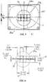
- FIGURES 3-12show that emitter 20 includes an LED light source that includes a submount 22 having an array of LEDs 24 on an LED-populated area 23 which has an aspect ratio greater than 1.
- LED-populated area 23also has a first maximum cross-dimension 15 and a second maximum cross-dimension 16 orthogonal to one another, first maximum cross-dimension 15 being greater than second maximum cross-dimension 16.
- FIGURES 3 and 4best show first lens 30 on submount 22 and overmolded over LED-populated area 23.
- FIGURES 5-12 and 27illustrate various configurations of LED-populated areas 23a-h with aspect ratios of at least about 1.25, at least about 1.5 and at least about 2.
- FIGURES 3-6show LED emitter 20a including rectangular LED-populated area 23a with eight LEDs 14 arranged in two rows of four LEDs 14 in each row. In FIGURE 6 , dimensions are indicated in millimeters in brackets, the first maximum cross dimension being [2.08], i . e ., 2.08 millimeters, and are indicated in inches under the brackets.
- FIGURE 12shows LED emitter 20g including forty-eight LEDs 14 arranged in four rows of twelve LEDs 14 in each row. The aspect ratios of LED-populated area 23a is about 2 and aspect ratio of LED-populated area 23g is about 3.
- FIGURES 7 and 8illustrate LED arrays 23b and 23c with LEDs 14 arranged in asymmetric configurations each having aspect ratio greater than 1.
- FIGURE 27Aillustrates an example of outer boundaries of LED-populated area 23h.
- FIGURE 27Bis an exemplary illustration of two orthogonal maximum cross-dimensions for the purpose of determination of an aspect ratio of a particular LED-populated area 23.
- FIGURE 27Bis also an exemplary illustration of a position of emitter axis 21 passing through geometric center 21a of minimum-area rectangle 21b bounding LED-populated area 23.
- FIGURES 6-10also show that the spacing and arrangement of the LEDs 14 on each LED-populated area 23 is such that the total LED area is at least about one-third of LED-populated area 23, as seen in FIGURES 8 and 27 .
- the spacing and arrangement of the LEDs 14are such that the total LED area is at least about two-thirds of LED-populated area 23b.
- the spacing and arrangement of the LEDs 14are such that the total LED area is at least about 90% of LED-populated areas 23a, 23d and 23e.
- FIGURE 8shows the spacing between LEDs 14 of array 24c is about 0.1 mm.
- the spacing between LEDs 14 of array 24ais about 0.075 mm.
- the spacing between LEDs 14 of array 24dis about 0.05 mm.
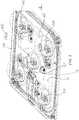
- FIGURE 2further illustrates another aspect of this invention which is lighting apparatus 100 which includes a plurality of LED arrays 24 spaced along a circuit board 11, a plurality of first lenses 30 each over a corresponding LED array 24, and a plurality of second lenses 40 each spaced over a corresponding one of first lenses 30.
- FIGURE 2also shows each first lens configured to refract LED-emitted light toward preferential side 2 with outer surface 32 of each first lens 30 being shaped for refraction of LED-emitted light toward preferential side 2, as best shown in FIGURES 3 and 4 , and having centerline 33 offset from corresponding light-emission axis 21 toward preferential side 2, as shown in FIGURES 4-6 .
- each of LED emitters 20is in the form of what is sometimes referred to as an LED package which includes LED array 24 on submount 22a and first lens 30 overmolded on submount 22a over its corresponding LED array 24.
- FIGURE 2further shows each of submounts 22a mounted on circuit board 11.
- FIGURE 11illustrates a plurality of LED arrays 24 mounted on a common submount 22 and a plurality of first lenses 30 overmolded on submount 22 over a respective one of LED arrays 24.
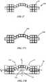
- FIGURES 2 and 13-18show the plurality of second lenses as portions of a one-piece lensing member 44.
- One-piece lensing member 44including a set of alignment protrusions 45 extending from a circuit-board-adjacent surface 46 of lensing member 44, best seen in FIGURES 2 , 13 and 14 .
- circuit board 11has a set of alignment holes formed in an LED-supporting surface 13 of circuit board 11 complementary to set alignment protrusions 45. Alignment protrusions 45 and alignment holes are engaged to accurately align secondary lenses 40 over their corresponding primary lenses 30.
- protrusions 45are first and second protrusions 451 and 452 extending from a circuit-board-adjacent surface 46 of lensing member 44, and that alignment holes defined by circuit board 11are first and second holes 121 and 122.
- First hole 121is complementary in shape to first protrusion 451 to fix the position of lensing member 44 along circuit board 11.
- Second hole 122receives second protrusion 452 to prevent rotation of lensing member 44 about first protrusion 451.
- Second 122 holeis elongate along a line extending between first and second holes 121 and 122 which facilitates engagement of the alignment features 45 and 121.
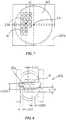
- FIGURES 20-26illustrate an alternative embodiment of lighting apparatus 10b which includes a hemispheric primary lens 30b and a separate-piece secondary lens 410 configured for refracting light from primary lens 30 toward preferential side 2 and creating an asymmetric illumination pattern such as type III or type IV light distribution patterns used for roadway lighting, as established by The Illumination Engineering Society (IES).
- Lens 410has an inner surface 41b spaced from first optical surface 31b and has a refracting portion 51b and a reflecting portion 54b.
- FIGURES 20 and 22best show refracting portion 51b surrounding first optical surface 31b and including front sector 52b and back sector 53b configured differently from one another. Reflecting portion 54b is around back sector 53b.
- FIGURES 24-26illustrate that reflecting portion 54b is positioned to receive light refracted by the back sector 53b for total internal reflection (TIR) toward outer surface 42b. It is seen in FIGURES 20 , 24-26 that outer surface 42b is configured to further direct light from inner surface 41b toward preferential side. Lens 410 is described in more detail in the parent Application Serial No. 12/475,194, filed May 29, 2009 .
- FIGURES 1 and 19best illustrate lighting apparatus 10 for preferential-side illumination with first lens 30 configured to direct LED-emitted light toward preferential side 2 and second lens 40 configured to further direct the light toward preferential side 2.
- first (or primary) lens 30 and second (or secondary) lens 40are shown as having asymmetric shapes with preferential direction being a one side direction with respect to emitter axis 21.
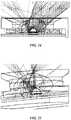
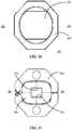
- FIGURES 28-36illustrate yet another alternative embodiment of lighting apparatus 10c with a separate-piece secondary lens 411 configured for directing a majority of light from primary lens 30c into an elongate distribution 3 with some lateral light along the sides of elongate distribution 3, as illustrated in FIGURES 34-36 , such that preferential side 2a are opposite sides along a longitudinal axial plane extending through emitter axis 21 and creating an non-rotationally symmetric elongate illumination pattern which is bilaterally symmetric in two main orthogonal directions.
- the illumination pattern produced by lens 411is useful for tall elongate passageways such as warehouse aisles.
- Lens 411has an inner surface 41c spaced from primary lens surface 30c and has a refracting surface portion 51c and a reflecting surface portion 54c.
- FIGURES 28, 29 and 31best show refracting portion 51c surrounding primary lens 30c and including front and back portions 52c and a pair of opposite lateral portions 53c, front and back portions 52c being substantially orthogonal to and extending between lateral portions 52c.
- Reflecting portion 54csubstantially surrounds refracting surface portion 51 c.
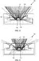
- FIGURES 32 and 33illustrate that reflecting portion 54c is positioned to receive substantially all forward and rearward light (best shown in FIGURE 32 ) and a portion of lateral light (best shown in FIGURE 33 ).
- Reflective surface portion 54cis configured for total internal reflection (TIR) of the received light toward outer surface 42c. It is also seen in FIGURES 32 and 33 that outer surface 42c receives light from refracting inner surface 51c and from reflecting surface 54c and forms elongate light distribution 3 (shown in FIGURES 34-36 ) by refracting such received light.
- Lens 411is described in more detail in Application Serial No. 13/408,882, filed February 29, 2012 .
Landscapes
- Engineering & Computer Science (AREA)
- General Engineering & Computer Science (AREA)
- Non-Portable Lighting Devices Or Systems Thereof (AREA)
Description
- This invention relates generally to the field of LED lighting apparatus and, more particularly, to the field of LED-based optical systems for use in LED lighting fixtures for which there are particular light-distribution requirements, such as what is sometimes referred to as preferential-side light distribution - for roadway light fixtures and the like.
- In recent years, the use of light-emitting diodes (LEDs) for various common lighting purposes has increased, and this trend has accelerated as advances have been made in LEDs, LED arrays, and specific components. Indeed, lighting applications which previously had typically been served by fixtures using what are known as high-intensity discharge (HID) lamps are now being served by LED lighting fixtures. Such lighting applications include, among a good many others, roadway lighting, factory lighting, parking lot lighting, and commercial building lighting.
- In many of such products, achieving high levels of illumination over large areas with specific light-distribution requirements is particularly important. One pertinent example is fixtures for roadway lighting, an application in which the fixtures are generally placed along roadway edges while light distribution is desired along a significant portion of roadway length and, of course, on the roadway itself - generally to the exclusion of significant light off the roadway.
- Providing roadway light from light fixtures along the roadway may be referred to as "preferential-side" illumination. In such situations it is desirable to minimize the use of large complex reflectors and/or varying orientations of multiple light sources to achieve desired illumination patterns. Achieving preferential-side illumination, or other desired illumination patterns, by means of LED-based optical systems, particularly without resorting to large complex reflectors or other complex means is highly desirable.
US 2010/0302786 A1 discloses a lighting apparatus comprising the features of the preamble ofclaim 1. - The present invention is a multi-lens LED-array optical system and improved LED-based lighting apparatus which satisfies all of the above-noted objects and purposes.
- According to this invention there is provided a lighting apparatus for preferential-side illumination having the features of
claim 1. An embodiment includes optical surfaces as follows: (1) a first optical surface which is a first-lens outer surface configured to refract light from the emitter; (2) a second optical surface which is a second-lens inner surface spaced from the first optical surface and having (a) a refracting portion surrounding the first optical surface and including front and back sectors configured differently from one another, and (b) a reflecting portion around the back sector, the reflecting portion positioned to receive light refracted by the back sector for total internal reflection (TIR) toward the preferential side; and (3) a third optical surface which is a second-lens outer surface configured to refract light from the second optical surface toward the preferential side. - In certain embodiments, the first lens is configured such that the first optical surface refracts LED-emitted light toward the preferential side. In some of such embodiments, the first optical surface is shaped for refraction of LED-emitted light toward the preferential side, while in others of such embodiments, the first optical surface has a centerline offset from the emitter axis toward the preferential side. In embodiments of the latter type, the first optical surface may be shaped for refraction of LED-emitted light toward the preferential side.
- In certain embodiments, the front sector of the refracting portion of the second optical surface has a substantially smooth surface configuration extending to the juncture of the front and back sectors. In such situations, it is preferred that the back sector of the refracting portion of the second optical surface include at least a pair of surface portions transverse to each other.
- In some embodiments, the back sector of the refracting portion of the second optical surface includes at least a pair of surface portions transverse to each other.
- In some embodiments, the emitter includes an LED light source that includes a submount having an LED-populated area which has an aspect ratio greater than 1, and an array of LEDs on the LED-populated area, and the first lens is on the submount over the LED-populated area. The aspect ratio may be at least about 1.25, or even at least about 1.5, and even as much as at least about 2. The LED-populated area is preferably rectangular.
- As used herein, the term "LED-populated area" means an area (i.e., an area on the submount) the outer boundaries of which include the outermost edges of the outermost LEDs (of the LED array) in any direction. As used herein, the term "aspect ratio" means the ratio of the maximum cross-dimension of the LED-populated area to the maximum of the cross-dimensions orthogonal thereto.
- As used herein, the term "emitter axis" means the line orthogonal to the plane defined by the LED-populated area and passing through the geometric center of the minimum-area rectangle bounding the LED-populated area,i.e., the center of the rectangle of minimum area which includes all of the LED-populated area.
- Another embodiment shows a lighting apparatus for preferential-side illumination, that includes: (1) a plurality of arrays of light-emitting diodes (LEDs) spaced along a circuit board, each array having first and second maximum cross-dimensions orthogonal to one another, the first maximum cross-dimension being greater than the second maximum cross-dimension, and each LED array defining a light-emission axis; (2) a plurality of first lenses each over a corresponding array of LEDs, each first lens having an outer surface configured to refract light from its corresponding LED array; and (3) a plurality of second lenses each spaced over a corresponding one of the first lenses, each second lens having (a) an inner surface configured to direct light toward the preferential side from its corresponding first-lens outer surface, and (b) an outer surface configured to refract light toward the preferential side from the inner surface.
- In such embodiments, each first lens preferably refracts LED-emitted light toward the preferential side. In some of such embodiments, each first lens is shaped for refraction of LED-emitted light toward the preferential side. In others of such embodiments, the outer surface of each first lens has a centerline offset from the corresponding light-emission axis toward the preferential side; in these embodiments, the outer surface of the first lens directs LED-emitted light toward the preferential side.
- It most embodiments of this invention, each first lens be overmolded over its corresponding LED array, forming what is sometimes referred to as an LED package.
- In certain embodiments, the plurality of LED arrays are mounted on a common submount. In certain other embodiments, LED array is on a submount and each of the submounts is mounted on the circuit board.
- In certain embodiments, the plurality of second lenses are portions of a one-piece lensing member.
- Referring again to the LED-populated areas, the spacing and arrangement of the LEDs on each LED-populated area may be such that the total LED area is at least about one-third of the LED-populated area. More specifically, the spacing and arrangement of the LEDs may be such that the total LED area is at least about two-thirds of the LED-populated area, or even as much as at least about 90% of the LED-populated area.
- As used herein, the term "total LED area" means the sum of the submount areas immediately beneath each of the LEDs of the LED array.
- In certain embodiments, the spacing between LEDs of the array is no more than about 1 millimeter (mm), or as little as no more than about 0.5 mm, or in some cases no more than about 0.1 mm. In some instances, the spacing is no more than about 0.075 mm, and even no more than about 0.05 mm.
- Another embodiment shows a lighting apparatus comprising (1) a plurality of arrays of light-emitting diodes (LEDs) spaced along a circuit board, each array having first and second maximum cross-dimensions orthogonal to one another, the first maximum cross-dimension being greater than the second maximum cross-dimension, and each LED array defining a light-emission axis; (2) a plurality of first lenses each over a corresponding array of LEDs, each first lens having an outer surface configured to refract light from its corresponding LED array; and (3) a plurality of second lenses each spaced over a corresponding one of the first lenses, each second lens having an inner surface and an outer surface which is configured to refract light from the inner surface.
- As already noted, the plurality of LED arrays may be mounted to a submount, each to a common submount or, more particularly, each LED on its own submount, with each of the submounts being mounted on the circuit board. And, as noted, each first lens may be overmolded over each LED array. And, as also noted above, the plurality of second lenses may be portions of a one-piece lensing member.
- In certain preferred embodiments, the first lens will have an outer surface configured to direct LED-emitted light toward the preferential side.
- Still other embodiments show a lighting apparatus including (1) a plurality of arrays of LEDs spaced along a circuit board, each array having first and second maximum cross-dimensions orthogonal to one another, the first maximum cross-dimension being greater than the second maximum cross-dimension, and each LED array defining a light-emission axis; and (2) a plurality of lenses each over a corresponding array of LEDs, each lens having an outer surface configured to refract light from its corresponding LED array.
- Yet another embodiment discloses a lighting apparatus including (1) an LED light source including a submount having an LED-populated area which has an aspect ratio greater than 1, the LED-populated area having an array of LEDs thereon, (2) a first lens on the submount over the LED array and having an outer surface configured to refract light from the LED array, and (3) a second lens spaced over the first lens, the second lens having an inner surface and an outer surface which is configured to refract light from the inner surface.
- Another embodiment shows a lighting apparatus for preferential-side illumination, the apparatus including an LED light source with an axis and having an asymmetric primary lens over the LED light source and an asymmetric secondary lens spaced over the primary lens.
- The term "asymmetric," as used herein with respect to lenses, when unmodified by any further limiting description, refers to a lens shape which is not rotationally symmetric about any axis perpendicular to its base plane. Types of asymmetric lenses include without limitation bilaterally symmetric lenses.
- In descriptions of the invention, including in the claims below, the terms "comprising," "including" and "having" (each in their various forms) and the term "with" are each to be understood as being open-ended, rather than limiting, terms.
FIGURE 1 is an enlarged cross-sectional perspective view of one embodiment of the inventive lighting apparatus.FIGURE 2 is a perspective view of the lighting apparatus including a plurality of the optical systems ofFIGURE 1 .FIGURE 3 is an enlarged perspective view of an embodiment of the LED package including an array of eight LEDs and an asymmetric primary lens overmolded over the LED array.FIGURE 4 is a cross-sectional side view of the LED package ofFIGURE 3 .FIGURE 5 is an enlarged plan view of the LED package ofFIGURE 3 .FIGURE 6 is an enlarged plan view of the LED array of the LED package ofFIGURE 3 and showing main dimensions of the LED array.FIGURES 7 and 8 are enlarged plan views of alternative LED arrays according to the present invention and having asymmetric shapes.FIGURES 9 and 10 are enlarged plan views of yet more alternative LED arrays each configured according to the present invention.FIGURE 11 is a perspective view of a plurality of LED light sources of this invention on a common submount.FIGURE 12 is an enlarged perspective view of an embodiment of the LED package including an array of forty-eight LEDs and an asymmetric primary lens overmolded over the LED array.FIGURE 13 is a transparent outer-surface perspective view of a single-piece lensing member.FIGURE 14 is a transparent inner-surface perspective view of a single-piece lensing member ofFIGURE 13 .FIGURE 15 is a non-transparent outer-surface perspective view of the single-piece lensing member ofFIGURE 13 .FIGURE 16 is a non-transparent outer-surface plan view of the single-piece lensing member ofFIGURE 13 .FIGURE 17 is a non-transparent back view of the single-piece lensing member ofFIGURE 13 .FIGURE 18 is a non-transparent side view of the single-piece lensing member ofFIGURE 13 .FIGURE 19 is an enlarged non-transparent cross-sectional side view of the optical system ofFIGURE 1 .FIGURE 20 is an enlarged perspective view of another embodiment of the inventive lighting apparatus including an optical system with a hemispherical first optical surface and asymmetric second and third optical surfaces.FIGURE 21 is an enlarged non-transparent cross-sectional side view of the optical system ofFIGURE 19 .FIGURE 22 is an enlarged transparent plan view of the lighting apparatus ofFIGURE 19 .FIGURE 23 is an enlarged transparent cross-sectional side view of the optical system ofFIGURE 19 .FIGURE 24 is an enlarged cross-sectional side view of the lighting apparatus ofFIGURE 19 showing LED-light refraction toward the preferential side and the secondary lens as a separate piece.FIGURE 25 is an enlarged cross-sectional perspective view of the lighting apparatus ofFIGURE 25 showing second-lens direction of LED light which is emitted toward a non-preferential side.FIGURE 26 is an enlarged fragmentary cross-sectional side view of the lighting apparatus ofFIGURE 25 .FIGURE 27 is an enlarged plan view of still another alternative configuration of an LED array.FIGURE 27A is an exemplary illustration of outer boundaries of an LED-populated area of the LED array ofFIGURE 27 .FIGURE 27B is an exemplary illustration of location of an emitter axis of LED array ofFIGURE 27 , and is an exemplary illustration of two orthogonal maximum cross-dimensions for the purpose of determination of an aspect ratio of an LED-populated area ofFIGURE 27A .FIGURE 28 is a transparent outer-surface perspective view of an alternative embodiment of the secondary lens.FIGURE 29 is a transparent inner-surface perspective view of the secondary lens ofFIGURE 28 .FIGURE 30 is a non-transparent outer-surface plan view of the lens ofFIGURE 28 .FIGURE 31 is a non-transparent inner-surface plan view of the secondary lens ofFIGURE 28 .FIGURE 32 is a front-to-back sectional view of the lens ofFIGURE 28 and illustrating forward and rearward light distributions.FIGURE 33 is a side-to-side sectional view of the lens ofFIGURE 28 and illustrating lateral light distribution.FIGURE 34 is a two-dimensional ISO plot of illumination intensity distribution by the lens ofFIGURE 28 on an illuminated surface substantially normal to the emitter axis.FIGURE 35 is a polar intensity distribution in a plane which includes the emitter axis, illustrating light directed as shown inFIGURE 33 .FIGURE 36 is a polar intensity distribution in a plane which includes the emitter axis and is substantially orthogonal the plane ofFIGURE 35 , illustrating light directed as shown inFIGURE 32 .FIGURES 1-26 illustrate a multi-lens LED-array optical system of an improved LED-based lighting apparatus.FIGURE 1 showslighting apparatus 10 for illumination toward apreferential side 2 from anLED light emitter 20 having anaxis 21.Lighting apparatus 10 has afirst lens 30 overemitter 20 and asecond lens 40 overfirst lens 30. The first lens is also sometimes referred to as a "primary" lens; and the second lens is also sometimes referred to as a "secondary" lens.Lighting apparatus 10 includes a firstoptical surface 31, a secondoptical surface 50 and a thirdoptical surface 43. Firstoptical surface 31 is anouter surface 32 offirst lens 30 and is configured to refract light fromemitter 20. Secondoptical surface 50 is aninner surface 41 ofsecond lens 40. Secondoptical surface 50 is spaced from firstoptical surface 31 and has a refractingportion 51 and a reflectingportion 54, as best seen inFIGURES 1 ,2 ,13 and 14 and 19-25.FIGURES 1 ,2 and19 bestshow refracting portion 51 surrounding firstoptical surface 31 and includingfront sector 52 and backsector 53 configured differently from one another. Reflectingportion 54 is around backsector 53 and is positioned to receive light refracted by theback sector 53 for total internal reflection (TIR) toward thepreferential side 2. It is seen inFIGURES 1 ,2 and13-25 that thirdoptical surface 43 is a second-lensouter surface 42 configured to refract light from secondoptical surface 50 toward thepreferential side 2.FIGURES 1-7 illustratefirst lens 30 as configured such that firstoptical surface 31 refracts LED-emitted light towardpreferential side 2.FIGURES 1-5 show firstoptical surface 31 shaped for refraction of LED-emitted light toward thepreferential side 2.FIGURES 3-7 show firstoptical surface 31 having a centerline 33 offset fromemitter axis 21 towardpreferential side 2.FIGURES 1-5 show LED emitters 20 which have both firstoptical surface 31 having itscenterline 33 offset fromemitter axis 21 towardpreferential side 2 and also being shaped for refraction of LED-emitted light towardpreferential side 2.FIGURES 1 ,13 ,14 and19 best illustrate thatfront sector 52 of refractingportion 51 of secondoptical surface 50 has a substantially smooth surface configuration extending tojuncture 55 of front andback sectors sector 53 includes a pair ofsurface portions FIGURES 3-12 show that emitter 20 includes an LED light source that includes asubmount 22 having an array of LEDs 24 on an LED-populated area 23 which has an aspect ratio greater than 1. LED-populated area 23 also has a firstmaximum cross-dimension 15 and a secondmaximum cross-dimension 16 orthogonal to one another, firstmaximum cross-dimension 15 being greater than secondmaximum cross-dimension 16.FIGURES 3 and 4 best showfirst lens 30 onsubmount 22 and overmolded over LED-populated area 23.FIGURES 5-12 and27 illustrate various configurations of LED-populatedareas 23a-h with aspect ratios of at least about 1.25, at least about 1.5 and at least about 2.FIGURES 3-6 show LED emitter 20a including rectangular LED-populatedarea 23a with eightLEDs 14 arranged in two rows of fourLEDs 14 in each row. InFIGURE 6 , dimensions are indicated in millimeters in brackets, the first maximum cross dimension being [2.08],i.e., 2.08 millimeters, and are indicated in inches under the brackets.FIGURE 12 showsLED emitter 20g including forty-eightLEDs 14 arranged in four rows of twelveLEDs 14 in each row. The aspect ratios of LED-populatedarea 23a is about 2 and aspect ratio of LED-populatedarea 23g is about 3.FIGURES 7 and 8 illustrateLED arrays 23b and 23c withLEDs 14 arranged in asymmetric configurations each having aspect ratio greater than 1.FIGURE 27A illustrates an example of outer boundaries of LED-populatedarea 23h.FIGURE 27B is an exemplary illustration of two orthogonal maximum cross-dimensions for the purpose of determination of an aspect ratio of a particular LED-populated area 23.FIGURE 27B is also an exemplary illustration of a position ofemitter axis 21 passing throughgeometric center 21a of minimum-area rectangle 21b bounding LED-populated area 23.FIGURES 6-10 also show that the spacing and arrangement of theLEDs 14 on each LED-populated area 23 is such that the total LED area is at least about one-third of LED-populated area 23, as seen inFIGURES 8 and27 . InFIGURE 7 , the spacing and arrangement of theLEDs 14 are such that the total LED area is at least about two-thirds of LED-populated area 23b. InFIGURES 6 ,9 and 10 , the spacing and arrangement of theLEDs 14 are such that the total LED area is at least about 90% of LED-populatedareas 23a, 23d and 23e.FIGURE 8 shows the spacing betweenLEDs 14 of array 24c is about 0.1 mm. InFIGURE 6 , the spacing betweenLEDs 14 ofarray 24a is about 0.075 mm. And, inFIGURE 9 the spacing betweenLEDs 14 ofarray 24d is about 0.05 mm.FIGURE 2 further illustrates another aspect of this invention which islighting apparatus 100 which includes a plurality of LED arrays 24 spaced along acircuit board 11, a plurality offirst lenses 30 each over a corresponding LED array 24, and a plurality ofsecond lenses 40 each spaced over a corresponding one offirst lenses 30.FIGURE 2 also shows each first lens configured to refract LED-emitted light towardpreferential side 2 withouter surface 32 of eachfirst lens 30 being shaped for refraction of LED-emitted light towardpreferential side 2, as best shown inFIGURES 3 and 4 , and havingcenterline 33 offset from corresponding light-emission axis 21 towardpreferential side 2, as shown inFIGURES 4-6 . InFIGURE 2 , each ofLED emitters 20 is in the form of what is sometimes referred to as an LED package which includes LED array 24 on submount 22a andfirst lens 30 overmolded on submount 22a over its corresponding LED array 24.FIGURE 2 further shows each of submounts 22a mounted oncircuit board 11.FIGURE 11 illustrates a plurality of LED arrays 24 mounted on acommon submount 22 and a plurality offirst lenses 30 overmolded onsubmount 22 over a respective one of LED arrays 24.FIGURES 2 and13-18 show the plurality of second lenses as portions of a one-piece lensing member 44. One-piece lensing member 44 including a set ofalignment protrusions 45 extending from a circuit-board-adjacent surface 46 oflensing member 44, best seen inFIGURES 2 ,13 and 14 . It is also seen inFIGURE 2 thatcircuit board 11 has a set of alignment holes formed in an LED-supporting surface 13 ofcircuit board 11 complementary to setalignment protrusions 45.Alignment protrusions 45 and alignment holes are engaged to accurately alignsecondary lenses 40 over their correspondingprimary lenses 30.- It is also seen in
FIGURES 2 ,13 and 14 that protrusions 45 are first andsecond protrusions adjacent surface 46 oflensing member 44, and that alignment holes defined by circuit board 11are first andsecond holes 121 and 122.First hole 121 is complementary in shape tofirst protrusion 451 to fix the position of lensingmember 44 alongcircuit board 11. Second hole 122 receivessecond protrusion 452 to prevent rotation of lensingmember 44 aboutfirst protrusion 451. Second 122 hole is elongate along a line extending between first andsecond holes 121 and 122 which facilitates engagement of the alignment features 45 and 121. FIGURES 20-26 illustrate an alternative embodiment of lighting apparatus 10b which includes a hemisphericprimary lens 30b and a separate-piecesecondary lens 410 configured for refracting light fromprimary lens 30 towardpreferential side 2 and creating an asymmetric illumination pattern such as type III or type IV light distribution patterns used for roadway lighting, as established by The Illumination Engineering Society (IES).Lens 410 has an inner surface 41b spaced from first optical surface 31b and has a refractingportion 51b and a reflectingportion 54b.FIGURES 20 and22 bestshow refracting portion 51b surrounding first optical surface 31b and includingfront sector 52b andback sector 53b configured differently from one another. Reflectingportion 54b is around backsector 53b.FIGURES 24-26 illustrate that reflectingportion 54b is positioned to receive light refracted by theback sector 53b for total internal reflection (TIR) towardouter surface 42b. It is seen inFIGURES 20 ,24-26 thatouter surface 42b is configured to further direct light from inner surface 41b toward preferential side.Lens 410 is described in more detail in the parent Application Serial No.12/475,194, filed May 29, 2009 FIGURES 1 and19 best illustratelighting apparatus 10 for preferential-side illumination withfirst lens 30 configured to direct LED-emitted light towardpreferential side 2 andsecond lens 40 configured tofurther direct the light towardpreferential side 2. Both first (or primary)lens 30 and second (or secondary)lens 40 are shown as having asymmetric shapes with preferential direction being a one side direction with respect toemitter axis 21.FIGURES 28-36 illustrate yet another alternative embodiment oflighting apparatus 10c with a separate-piecesecondary lens 411 configured for directing a majority of light fromprimary lens 30c into an elongate distribution 3 with some lateral light along the sides of elongate distribution 3, as illustrated inFIGURES 34-36 , such thatpreferential side 2a are opposite sides along a longitudinal axial plane extending throughemitter axis 21 and creating an non-rotationally symmetric elongate illumination pattern which is bilaterally symmetric in two main orthogonal directions. The illumination pattern produced bylens 411 is useful for tall elongate passageways such as warehouse aisles.Lens 411 has aninner surface 41c spaced fromprimary lens surface 30c and has a refractingsurface portion 51c and a reflectingsurface portion 54c.FIGURES 28, 29 and31 bestshow refracting portion 51c surroundingprimary lens 30c and including front andback portions 52c and a pair of oppositelateral portions 53c, front andback portions 52c being substantially orthogonal to and extending betweenlateral portions 52c. Reflectingportion 54c substantially surrounds refractingsurface portion 51 c.FIGURES 32 and 33 illustrate that reflectingportion 54c is positioned to receive substantially all forward and rearward light (best shown inFIGURE 32 ) and a portion of lateral light (best shown inFIGURE 33 ).Reflective surface portion 54c is configured for total internal reflection (TIR) of the received light towardouter surface 42c. It is also seen inFIGURES 32 and 33 thatouter surface 42c receives light from refractinginner surface 51c and from reflectingsurface 54c and forms elongate light distribution 3 (shown inFIGURES 34-36 ) by refracting such received light.Lens 411 is described in more detail in Application Serial No.13/408,882, filed February 29, 2012
Claims (15)
- Lighting apparatus (10) for preferential-side (2) illumination, the apparatus (10) including an LED light emitter (20) having an axis (21) which is a line orthogonal to a plane defined by the light emitter (20) and passing through the geometric center of an area of the emitter on the plane, the apparatus (10) comprising:• a first lens (30) over the emitter (20) and configured to preferentially direct LED-emitted light toward the preferential side (2); and• a second lens (40) spaced over the first lens (30) and configured to further preferentially direct the light toward the preferential side (2)characterized in that
the first lens (30) has a centerline (33) which is offset from the emitter axis (21) toward the preferential side (2). - The lighting apparatus (10) of claim 1 wherein the first lens (30) has an outer surface (32) configured to direct LED-emitted light toward the preferential side (2).
- The lighting apparatus (10) of claim 1 wherein the second lens (40) includes:• an inner surface (41) configured to preferentially direct light from the first-lens (30) outer surface (32); and• an outer surface (42) configured to direct light toward the preferential side (2) from the inner surface (41).
- The lighting apparatus (10) of claim 3 wherein the inner surface (41) of the second lens (40) includes:• a refracting portion (51; 51b) surrounding the first lens (30) and including front and back sectors (52, 53; 52b, 53b); and• a reflecting portion (54; 54b) around the back sector (53; 53b), the reflecting portion (54; 54b) positioned to receive light refracted by the back sector (53; 53b) for total internal reflection (TIR) toward the preferential side (2).
- The lighting apparatus (10) of claim 4 wherein the back sector (53; 53b) of the refracting portion (51; 51b) of the second lens (40) includes at least a pair of surface portions (53a, 53b) transverse to each other.
- The lighting apparatus (10) of claim 5 wherein the front sector (52; 52b) of the refracting portion (51; 51b) of the second lens (40) has a substantially smooth surface configuration extending to the juncture (55) of the front and back sectors (52, 53; 52b, 53b).
- The lighting apparatus (10) of claim 4 wherein the refracting portion (51; 51b) of the second-lens (40) inner surface (41) includes front and back sectors (52b, 53b) configured differently from one another.
- The lighting apparatus (10) of claim 1 wherein:• the emitter (20) includes an LED light source which includes a submount (22) having an LED-populated area (23) which has an aspect ratio greater than 1, and an array of LEDs (24) on the LED-populated area (23); and• the first lens (30) is on the submount (22) over the LED-populated area (23).
- The lighting apparatus (10) of claim 8 wherein the LED-populated area (23) is rectangular.
- The LED lighting apparatus (10) of claim 8 wherein the first lens (30) is overmolded on the submount (22).
- The lighting apparatus (10) of claim 1 further comprising:• a plurality of arrays of light-emitting diodes (LEDs) (24) spaced along a circuit board (11), each array (24) having first and second maximum cross-dimensions (15, 16) orthogonal to one another, the first maximum cross-dimension (15) being greater than the second maximum cross-dimension (16), and each LED array (24) defining a light-emission axis (21);• a plurality of first lenses (30) each over a corresponding array of LEDs (24), each first lens (30) having an outer surface (32) configured to refract light from its corresponding LED array (24); and• a plurality of second lenses (40) each spaced over a corresponding one of the first lenses (30), each second lens (40) having an inner surface (41) and an outer surface (42) which is configured to refract light from the inner surface (41).
- The lighting apparatus (10) of claim 11 wherein the plurality of LED arrays (24) are mounted on a common submount (22).
- The lighting apparatus (10) of claim 11 wherein each LED array (24) is on a submount (22) and each of the submounts (22) is mounted on the circuit board (11).
- The lighting apparatus (10) of claim 11 wherein each first lens (30) is overmolded over each LED array (24).
- The lighting apparatus (10) of claim 14 wherein each first lens (30) has an outer surface (32) configured to direct LED-emitted light toward the preferential side (2).
Applications Claiming Priority (2)
| Application Number | Priority Date | Filing Date | Title |
|---|---|---|---|
| US13/441,540US9255686B2 (en) | 2009-05-29 | 2012-04-06 | Multi-lens LED-array optic system |
| PCT/US2013/035287WO2013152199A1 (en) | 2012-04-06 | 2013-04-04 | Multi-lens led-array optic system |
Publications (3)
| Publication Number | Publication Date |
|---|---|
| EP2834556A1 EP2834556A1 (en) | 2015-02-11 |
| EP2834556A4 EP2834556A4 (en) | 2015-12-23 |
| EP2834556B1true EP2834556B1 (en) | 2017-08-02 |
Family
ID=49301047
Family Applications (1)
| Application Number | Title | Priority Date | Filing Date |
|---|---|---|---|
| EP13772520.6AActiveEP2834556B1 (en) | 2012-04-06 | 2013-04-04 | Multi-lens led-array optic system |
Country Status (2)
| Country | Link |
|---|---|
| EP (1) | EP2834556B1 (en) |
| WO (1) | WO2013152199A1 (en) |
Families Citing this family (2)
| Publication number | Priority date | Publication date | Assignee | Title |
|---|---|---|---|---|
| EP2924345B1 (en)* | 2014-03-28 | 2018-07-18 | Swarco Futurit Verkehrssignalsysteme Ges.m.b.H. | Lighting devices with asymmetrical light distribution |
| WO2016071845A1 (en)* | 2014-11-06 | 2016-05-12 | Philips Lighting Holding B.V. | Asymmetric lens and linear lighting apparatus |
Family Cites Families (11)
| Publication number | Priority date | Publication date | Assignee | Title |
|---|---|---|---|---|
| US7821023B2 (en)* | 2005-01-10 | 2010-10-26 | Cree, Inc. | Solid state lighting component |
| WO2006111805A1 (en)* | 2005-04-16 | 2006-10-26 | Acol Technologies Sa | Optical light source having displaced axes |
| US8348475B2 (en) | 2008-05-23 | 2013-01-08 | Ruud Lighting, Inc. | Lens with controlled backlight management |
| US7766509B1 (en)* | 2008-06-13 | 2010-08-03 | Lumec Inc. | Orientable lens for an LED fixture |
| US7891835B2 (en)* | 2008-07-15 | 2011-02-22 | Ruud Lighting, Inc. | Light-directing apparatus with protected reflector-shield and lighting fixture utilizing same |
| CN103459919B (en)* | 2008-08-14 | 2016-10-26 | 库帕技术公司 | For biasing the LED device that angle pencil of ray generates |
| CN102032526B (en)* | 2009-09-30 | 2013-08-07 | 富准精密工业(深圳)有限公司 | LED module |
| CN201593753U (en)* | 2010-01-12 | 2010-09-29 | 雷笛克光学股份有限公司 | Asymmetric LED lens for street lamp |
| DE102010014289B4 (en)* | 2010-04-08 | 2014-03-27 | Trilux Gmbh & Co. Kg | Light module and luminaire with light module |
| US20120051047A1 (en)* | 2010-08-30 | 2012-03-01 | Edison Opto Corporation | Street lamp |
| US9541257B2 (en) | 2012-02-29 | 2017-01-10 | Cree, Inc. | Lens for primarily-elongate light distribution |
- 2013
- 2013-04-04EPEP13772520.6Apatent/EP2834556B1/enactiveActive
- 2013-04-04WOPCT/US2013/035287patent/WO2013152199A1/enactiveApplication Filing
Non-Patent Citations (1)
| Title |
|---|
| None* |
Also Published As
| Publication number | Publication date |
|---|---|
| EP2834556A4 (en) | 2015-12-23 |
| WO2013152199A1 (en) | 2013-10-10 |
| EP2834556A1 (en) | 2015-02-11 |
Similar Documents
| Publication | Publication Date | Title |
|---|---|---|
| US9689552B2 (en) | Multi-lens LED-array optic system | |
| EP2435756B1 (en) | Lens with controlled backlight management | |
| US7810963B2 (en) | Light emitting diode module with improved light distribution uniformity | |
| US9217854B2 (en) | Lens with controlled light refraction | |
| US7866837B2 (en) | Skew light illumination lens device | |
| CN114787555B (en) | Lamp for a motor vehicle comprising a light guide | |
| US9410674B2 (en) | LED lens | |
| US9541258B2 (en) | Lens for wide lateral-angle distribution | |
| EP3169547B1 (en) | Vehicle lighting module | |
| US20140126206A1 (en) | Lens with Controlled Light Refraction | |
| CN213066002U (en) | Optical device, luminaire and mould for modifying light distribution | |
| US9423096B2 (en) | LED lighting apparatus | |
| US10948150B2 (en) | Multi-beam vehicle light | |
| US9523479B2 (en) | LED lens | |
| EP2834556B1 (en) | Multi-lens led-array optic system | |
| EP3149396B1 (en) | Luminaire, especially for road lighting | |
| WO2013169643A1 (en) | Lens for wide lateral-angle distribution | |
| AU2013204682B2 (en) | Lens with controlled backlight management | |
| WO2013043743A1 (en) | Led retrofit lighting fixture | |
| HK1164979B (en) | Lens with controlled backlight management |
Legal Events
| Date | Code | Title | Description |
|---|---|---|---|
| PUAI | Public reference made under article 153(3) epc to a published international application that has entered the european phase | Free format text:ORIGINAL CODE: 0009012 | |
| 17P | Request for examination filed | Effective date:20141014 | |
| AK | Designated contracting states | Kind code of ref document:A1 Designated state(s):AL AT BE BG CH CY CZ DE DK EE ES FI FR GB GR HR HU IE IS IT LI LT LU LV MC MK MT NL NO PL PT RO RS SE SI SK SM TR | |
| AX | Request for extension of the european patent | Extension state:BA ME | |
| DAX | Request for extension of the european patent (deleted) | ||
| RA4 | Supplementary search report drawn up and despatched (corrected) | Effective date:20151119 | |
| RIC1 | Information provided on ipc code assigned before grant | Ipc:F21V 5/08 20060101ALI20151113BHEP Ipc:F21V 5/00 20150101AFI20151113BHEP Ipc:F21V 13/04 20060101ALI20151113BHEP Ipc:F21V 7/00 20060101ALI20151113BHEP | |
| GRAP | Despatch of communication of intention to grant a patent | Free format text:ORIGINAL CODE: EPIDOSNIGR1 | |
| RIC1 | Information provided on ipc code assigned before grant | Ipc:F21V 7/00 20060101ALI20170130BHEP Ipc:F21V 13/04 20060101ALI20170130BHEP Ipc:F21V 5/00 20150101AFI20170130BHEP Ipc:F21V 5/08 20060101ALI20170130BHEP Ipc:F21Y 115/10 20160101ALN20170130BHEP | |
| INTG | Intention to grant announced | Effective date:20170224 | |
| GRAS | Grant fee paid | Free format text:ORIGINAL CODE: EPIDOSNIGR3 | |
| GRAA | (expected) grant | Free format text:ORIGINAL CODE: 0009210 | |
| AK | Designated contracting states | Kind code of ref document:B1 Designated state(s):AL AT BE BG CH CY CZ DE DK EE ES FI FR GB GR HR HU IE IS IT LI LT LU LV MC MK MT NL NO PL PT RO RS SE SI SK SM TR | |
| REG | Reference to a national code | Ref country code:CH Ref legal event code:EP Ref country code:AT Ref legal event code:REF Ref document number:914879 Country of ref document:AT Kind code of ref document:T Effective date:20170815 | |
| REG | Reference to a national code | Ref country code:IE Ref legal event code:FG4D | |
| REG | Reference to a national code | Ref country code:DE Ref legal event code:R096 Ref document number:602013024438 Country of ref document:DE | |
| REG | Reference to a national code | Ref country code:NL Ref legal event code:FP | |
| REG | Reference to a national code | Ref country code:AT Ref legal event code:MK05 Ref document number:914879 Country of ref document:AT Kind code of ref document:T Effective date:20170802 | |
| REG | Reference to a national code | Ref country code:LT Ref legal event code:MG4D | |
| PG25 | Lapsed in a contracting state [announced via postgrant information from national office to epo] | Ref country code:LT Free format text:LAPSE BECAUSE OF FAILURE TO SUBMIT A TRANSLATION OF THE DESCRIPTION OR TO PAY THE FEE WITHIN THE PRESCRIBED TIME-LIMIT Effective date:20170802 Ref country code:NO Free format text:LAPSE BECAUSE OF FAILURE TO SUBMIT A TRANSLATION OF THE DESCRIPTION OR TO PAY THE FEE WITHIN THE PRESCRIBED TIME-LIMIT Effective date:20171102 Ref country code:HR Free format text:LAPSE BECAUSE OF FAILURE TO SUBMIT A TRANSLATION OF THE DESCRIPTION OR TO PAY THE FEE WITHIN THE PRESCRIBED TIME-LIMIT Effective date:20170802 Ref country code:FI Free format text:LAPSE BECAUSE OF FAILURE TO SUBMIT A TRANSLATION OF THE DESCRIPTION OR TO PAY THE FEE WITHIN THE PRESCRIBED TIME-LIMIT Effective date:20170802 Ref country code:AT Free format text:LAPSE BECAUSE OF FAILURE TO SUBMIT A TRANSLATION OF THE DESCRIPTION OR TO PAY THE FEE WITHIN THE PRESCRIBED TIME-LIMIT Effective date:20170802 Ref country code:SE Free format text:LAPSE BECAUSE OF FAILURE TO SUBMIT A TRANSLATION OF THE DESCRIPTION OR TO PAY THE FEE WITHIN THE PRESCRIBED TIME-LIMIT Effective date:20170802 | |
| PG25 | Lapsed in a contracting state [announced via postgrant information from national office to epo] | Ref country code:ES Free format text:LAPSE BECAUSE OF FAILURE TO SUBMIT A TRANSLATION OF THE DESCRIPTION OR TO PAY THE FEE WITHIN THE PRESCRIBED TIME-LIMIT Effective date:20170802 Ref country code:IS Free format text:LAPSE BECAUSE OF FAILURE TO SUBMIT A TRANSLATION OF THE DESCRIPTION OR TO PAY THE FEE WITHIN THE PRESCRIBED TIME-LIMIT Effective date:20171202 Ref country code:RS Free format text:LAPSE BECAUSE OF FAILURE TO SUBMIT A TRANSLATION OF THE DESCRIPTION OR TO PAY THE FEE WITHIN THE PRESCRIBED TIME-LIMIT Effective date:20170802 Ref country code:PL Free format text:LAPSE BECAUSE OF FAILURE TO SUBMIT A TRANSLATION OF THE DESCRIPTION OR TO PAY THE FEE WITHIN THE PRESCRIBED TIME-LIMIT Effective date:20170802 Ref country code:BG Free format text:LAPSE BECAUSE OF FAILURE TO SUBMIT A TRANSLATION OF THE DESCRIPTION OR TO PAY THE FEE WITHIN THE PRESCRIBED TIME-LIMIT Effective date:20171102 Ref country code:LV Free format text:LAPSE BECAUSE OF FAILURE TO SUBMIT A TRANSLATION OF THE DESCRIPTION OR TO PAY THE FEE WITHIN THE PRESCRIBED TIME-LIMIT Effective date:20170802 Ref country code:GR Free format text:LAPSE BECAUSE OF FAILURE TO SUBMIT A TRANSLATION OF THE DESCRIPTION OR TO PAY THE FEE WITHIN THE PRESCRIBED TIME-LIMIT Effective date:20171103 | |
| PG25 | Lapsed in a contracting state [announced via postgrant information from national office to epo] | Ref country code:RO Free format text:LAPSE BECAUSE OF FAILURE TO SUBMIT A TRANSLATION OF THE DESCRIPTION OR TO PAY THE FEE WITHIN THE PRESCRIBED TIME-LIMIT Effective date:20170802 Ref country code:CZ Free format text:LAPSE BECAUSE OF FAILURE TO SUBMIT A TRANSLATION OF THE DESCRIPTION OR TO PAY THE FEE WITHIN THE PRESCRIBED TIME-LIMIT Effective date:20170802 Ref country code:DK Free format text:LAPSE BECAUSE OF FAILURE TO SUBMIT A TRANSLATION OF THE DESCRIPTION OR TO PAY THE FEE WITHIN THE PRESCRIBED TIME-LIMIT Effective date:20170802 | |
| REG | Reference to a national code | Ref country code:DE Ref legal event code:R097 Ref document number:602013024438 Country of ref document:DE | |
| PG25 | Lapsed in a contracting state [announced via postgrant information from national office to epo] | Ref country code:SM Free format text:LAPSE BECAUSE OF FAILURE TO SUBMIT A TRANSLATION OF THE DESCRIPTION OR TO PAY THE FEE WITHIN THE PRESCRIBED TIME-LIMIT Effective date:20170802 Ref country code:IT Free format text:LAPSE BECAUSE OF FAILURE TO SUBMIT A TRANSLATION OF THE DESCRIPTION OR TO PAY THE FEE WITHIN THE PRESCRIBED TIME-LIMIT Effective date:20170802 Ref country code:EE Free format text:LAPSE BECAUSE OF FAILURE TO SUBMIT A TRANSLATION OF THE DESCRIPTION OR TO PAY THE FEE WITHIN THE PRESCRIBED TIME-LIMIT Effective date:20170802 Ref country code:SK Free format text:LAPSE BECAUSE OF FAILURE TO SUBMIT A TRANSLATION OF THE DESCRIPTION OR TO PAY THE FEE WITHIN THE PRESCRIBED TIME-LIMIT Effective date:20170802 | |
| PLBE | No opposition filed within time limit | Free format text:ORIGINAL CODE: 0009261 | |
| STAA | Information on the status of an ep patent application or granted ep patent | Free format text:STATUS: NO OPPOSITION FILED WITHIN TIME LIMIT | |
| 26N | No opposition filed | Effective date:20180503 | |
| PG25 | Lapsed in a contracting state [announced via postgrant information from national office to epo] | Ref country code:SI Free format text:LAPSE BECAUSE OF FAILURE TO SUBMIT A TRANSLATION OF THE DESCRIPTION OR TO PAY THE FEE WITHIN THE PRESCRIBED TIME-LIMIT Effective date:20170802 | |
| PG25 | Lapsed in a contracting state [announced via postgrant information from national office to epo] | Ref country code:MC Free format text:LAPSE BECAUSE OF FAILURE TO SUBMIT A TRANSLATION OF THE DESCRIPTION OR TO PAY THE FEE WITHIN THE PRESCRIBED TIME-LIMIT Effective date:20170802 | |
| REG | Reference to a national code | Ref country code:CH Ref legal event code:PL | |
| REG | Reference to a national code | Ref country code:BE Ref legal event code:MM Effective date:20180430 | |
| GBPC | Gb: european patent ceased through non-payment of renewal fee | Effective date:20180404 | |
| REG | Reference to a national code | Ref country code:IE Ref legal event code:MM4A | |
| PG25 | Lapsed in a contracting state [announced via postgrant information from national office to epo] | Ref country code:LU Free format text:LAPSE BECAUSE OF NON-PAYMENT OF DUE FEES Effective date:20180404 | |
| PG25 | Lapsed in a contracting state [announced via postgrant information from national office to epo] | Ref country code:LI Free format text:LAPSE BECAUSE OF NON-PAYMENT OF DUE FEES Effective date:20180430 Ref country code:CH Free format text:LAPSE BECAUSE OF NON-PAYMENT OF DUE FEES Effective date:20180430 Ref country code:BE Free format text:LAPSE BECAUSE OF NON-PAYMENT OF DUE FEES Effective date:20180430 Ref country code:GB Free format text:LAPSE BECAUSE OF NON-PAYMENT OF DUE FEES Effective date:20180404 | |
| PG25 | Lapsed in a contracting state [announced via postgrant information from national office to epo] | Ref country code:FR Free format text:LAPSE BECAUSE OF NON-PAYMENT OF DUE FEES Effective date:20180430 Ref country code:IE Free format text:LAPSE BECAUSE OF NON-PAYMENT OF DUE FEES Effective date:20180404 | |
| REG | Reference to a national code | Ref country code:DE Ref legal event code:R082 Ref document number:602013024438 Country of ref document:DE Representative=s name:KROHER - STROBEL RECHTS- UND PATENTANWAELTE PA, DE Ref country code:DE Ref legal event code:R081 Ref document number:602013024438 Country of ref document:DE Owner name:IDEAL INDUSTRIES LIGHTING LLC, SYCAMORE, US Free format text:FORMER OWNER: CREE, INC., DURHAM, N.C., US Ref country code:DE Ref legal event code:R082 Ref document number:602013024438 Country of ref document:DE Representative=s name:KROHER STROBEL RECHTS- UND PATENTANWAELTE PART, DE | |
| PG25 | Lapsed in a contracting state [announced via postgrant information from national office to epo] | Ref country code:MT Free format text:LAPSE BECAUSE OF NON-PAYMENT OF DUE FEES Effective date:20180404 | |
| REG | Reference to a national code | Ref country code:NL Ref legal event code:PD Owner name:IDEAL INDUSTRIES LIGHTING LLC; US Free format text:DETAILS ASSIGNMENT: CHANGE OF OWNER(S), ASSIGNMENT; FORMER OWNER NAME: CREE, INC. Effective date:20200224 | |
| PG25 | Lapsed in a contracting state [announced via postgrant information from national office to epo] | Ref country code:TR Free format text:LAPSE BECAUSE OF FAILURE TO SUBMIT A TRANSLATION OF THE DESCRIPTION OR TO PAY THE FEE WITHIN THE PRESCRIBED TIME-LIMIT Effective date:20170802 | |
| PG25 | Lapsed in a contracting state [announced via postgrant information from national office to epo] | Ref country code:PT Free format text:LAPSE BECAUSE OF FAILURE TO SUBMIT A TRANSLATION OF THE DESCRIPTION OR TO PAY THE FEE WITHIN THE PRESCRIBED TIME-LIMIT Effective date:20170802 Ref country code:HU Free format text:LAPSE BECAUSE OF FAILURE TO SUBMIT A TRANSLATION OF THE DESCRIPTION OR TO PAY THE FEE WITHIN THE PRESCRIBED TIME-LIMIT; INVALID AB INITIO Effective date:20130404 | |
| PG25 | Lapsed in a contracting state [announced via postgrant information from national office to epo] | Ref country code:MK Free format text:LAPSE BECAUSE OF NON-PAYMENT OF DUE FEES Effective date:20170802 Ref country code:CY Free format text:LAPSE BECAUSE OF FAILURE TO SUBMIT A TRANSLATION OF THE DESCRIPTION OR TO PAY THE FEE WITHIN THE PRESCRIBED TIME-LIMIT Effective date:20170802 | |
| PG25 | Lapsed in a contracting state [announced via postgrant information from national office to epo] | Ref country code:AL Free format text:LAPSE BECAUSE OF FAILURE TO SUBMIT A TRANSLATION OF THE DESCRIPTION OR TO PAY THE FEE WITHIN THE PRESCRIBED TIME-LIMIT Effective date:20170802 | |
| PGFP | Annual fee paid to national office [announced via postgrant information from national office to epo] | Ref country code:NL Payment date:20230426 Year of fee payment:11 | |
| REG | Reference to a national code | Ref country code:NL Ref legal event code:MM Effective date:20240501 | |
| REG | Reference to a national code | Ref country code:DE Ref legal event code:R081 Ref document number:602013024438 Country of ref document:DE Owner name:CREE LIGHTING USA LLC (N.D.GES.D. STAATES DELA, US Free format text:FORMER OWNER: IDEAL INDUSTRIES LIGHTING LLC, SYCAMORE, IL, US | |
| PG25 | Lapsed in a contracting state [announced via postgrant information from national office to epo] | Ref country code:NL Free format text:LAPSE BECAUSE OF NON-PAYMENT OF DUE FEES Effective date:20240501 | |
| PG25 | Lapsed in a contracting state [announced via postgrant information from national office to epo] | Ref country code:NL Free format text:LAPSE BECAUSE OF NON-PAYMENT OF DUE FEES Effective date:20240501 | |
| PGFP | Annual fee paid to national office [announced via postgrant information from national office to epo] | Ref country code:DE Payment date:20250429 Year of fee payment:13 |