EP2833777B1 - Polarimetric accessory for colposcope - Google Patents
Polarimetric accessory for colposcopeDownload PDFInfo
- Publication number
- EP2833777B1 EP2833777B1EP13772208.8AEP13772208AEP2833777B1EP 2833777 B1EP2833777 B1EP 2833777B1EP 13772208 AEP13772208 AEP 13772208AEP 2833777 B1EP2833777 B1EP 2833777B1
- Authority
- EP
- European Patent Office
- Prior art keywords
- image
- polarization
- specimen
- images
- flux
- Prior art date
- Legal status (The legal status is an assumption and is not a legal conclusion. Google has not performed a legal analysis and makes no representation as to the accuracy of the status listed.)
- Active
Links
Images


Classifications
- A—HUMAN NECESSITIES
- A61—MEDICAL OR VETERINARY SCIENCE; HYGIENE
- A61B—DIAGNOSIS; SURGERY; IDENTIFICATION
- A61B1/00—Instruments for performing medical examinations of the interior of cavities or tubes of the body by visual or photographical inspection, e.g. endoscopes; Illuminating arrangements therefor
- A61B1/303—Instruments for performing medical examinations of the interior of cavities or tubes of the body by visual or photographical inspection, e.g. endoscopes; Illuminating arrangements therefor for the vagina, i.e. vaginoscopes
- A—HUMAN NECESSITIES
- A61—MEDICAL OR VETERINARY SCIENCE; HYGIENE
- A61B—DIAGNOSIS; SURGERY; IDENTIFICATION
- A61B1/00—Instruments for performing medical examinations of the interior of cavities or tubes of the body by visual or photographical inspection, e.g. endoscopes; Illuminating arrangements therefor
- A61B1/00002—Operational features of endoscopes
- A61B1/00004—Operational features of endoscopes characterised by electronic signal processing
- A61B1/00009—Operational features of endoscopes characterised by electronic signal processing of image signals during a use of endoscope
- A61B1/000096—Operational features of endoscopes characterised by electronic signal processing of image signals during a use of endoscope using artificial intelligence
- A—HUMAN NECESSITIES
- A61—MEDICAL OR VETERINARY SCIENCE; HYGIENE
- A61B—DIAGNOSIS; SURGERY; IDENTIFICATION
- A61B1/00—Instruments for performing medical examinations of the interior of cavities or tubes of the body by visual or photographical inspection, e.g. endoscopes; Illuminating arrangements therefor
- A61B1/00002—Operational features of endoscopes
- A61B1/0002—Operational features of endoscopes provided with data storages
- A—HUMAN NECESSITIES
- A61—MEDICAL OR VETERINARY SCIENCE; HYGIENE
- A61B—DIAGNOSIS; SURGERY; IDENTIFICATION
- A61B1/00—Instruments for performing medical examinations of the interior of cavities or tubes of the body by visual or photographical inspection, e.g. endoscopes; Illuminating arrangements therefor
- A61B1/00002—Operational features of endoscopes
- A61B1/00043—Operational features of endoscopes provided with output arrangements
- A61B1/00045—Display arrangement
- A61B1/00052—Display arrangement positioned at proximal end of the endoscope body
- A—HUMAN NECESSITIES
- A61—MEDICAL OR VETERINARY SCIENCE; HYGIENE
- A61B—DIAGNOSIS; SURGERY; IDENTIFICATION
- A61B1/00—Instruments for performing medical examinations of the interior of cavities or tubes of the body by visual or photographical inspection, e.g. endoscopes; Illuminating arrangements therefor
- A61B1/00163—Optical arrangements
- A61B1/00193—Optical arrangements adapted for stereoscopic vision
- A—HUMAN NECESSITIES
- A61—MEDICAL OR VETERINARY SCIENCE; HYGIENE
- A61B—DIAGNOSIS; SURGERY; IDENTIFICATION
- A61B1/00—Instruments for performing medical examinations of the interior of cavities or tubes of the body by visual or photographical inspection, e.g. endoscopes; Illuminating arrangements therefor
- A61B1/00163—Optical arrangements
- A61B1/00195—Optical arrangements with eyepieces
- A61B1/00197—Optical arrangements with eyepieces characterised by multiple eyepieces
- A—HUMAN NECESSITIES
- A61—MEDICAL OR VETERINARY SCIENCE; HYGIENE
- A61B—DIAGNOSIS; SURGERY; IDENTIFICATION
- A61B1/00—Instruments for performing medical examinations of the interior of cavities or tubes of the body by visual or photographical inspection, e.g. endoscopes; Illuminating arrangements therefor
- A61B1/04—Instruments for performing medical examinations of the interior of cavities or tubes of the body by visual or photographical inspection, e.g. endoscopes; Illuminating arrangements therefor combined with photographic or television appliances
- A61B1/042—Instruments for performing medical examinations of the interior of cavities or tubes of the body by visual or photographical inspection, e.g. endoscopes; Illuminating arrangements therefor combined with photographic or television appliances characterised by a proximal camera, e.g. a CCD camera
- A—HUMAN NECESSITIES
- A61—MEDICAL OR VETERINARY SCIENCE; HYGIENE
- A61B—DIAGNOSIS; SURGERY; IDENTIFICATION
- A61B1/00—Instruments for performing medical examinations of the interior of cavities or tubes of the body by visual or photographical inspection, e.g. endoscopes; Illuminating arrangements therefor
- A61B1/06—Instruments for performing medical examinations of the interior of cavities or tubes of the body by visual or photographical inspection, e.g. endoscopes; Illuminating arrangements therefor with illuminating arrangements
- A61B1/0646—Instruments for performing medical examinations of the interior of cavities or tubes of the body by visual or photographical inspection, e.g. endoscopes; Illuminating arrangements therefor with illuminating arrangements with illumination filters
Definitions
- the disclosurepertains to polarization-based colposcopy.
- Cervical examinations and the assessment of the tissues of the vagina and the vulvaare often performed with a binocular microscope configured to have a long working distance (about 30 cm) and a magnification of up to 25.
- a video or still cameracan be provided to recorded images produced by the microscope.
- Examination based on such imagesis known as colposcopy and such specially adapted microscope systems are known as colposcopes.
- Colposcopyis an important technique for the detection of diseases such as cervical cancer.
- specular reflections from tissue surfacescan make colposcopic tissue assessments difficult as specular reflections can obscure sub-surface structures.
- US2007/0146632discloses an advanced polarization imaging method and apparatus for retinal imaging, liquid crystal testing, active remote sensing and other applications.
- a method, apparatus and computer program product for identifying features in a sample by analyzing Mueller matrices to calculate an average degree of polarization, a weighted average degree of polarization, a degree of polarization map, a degree of polarization surfaceAlso, a method, apparatus and computer program product for identifying features in a sample by analyzing Mueller matrices to calculate depolarization relative to a retardance axis and/or a diattentuation axis, and to calculate a ratio of diattenuation to polarizance or ratios of row and column magnitudes. Also a method for retinal polarimetry, including a non-depolarizing light tube configured for insertion into the eye.
- US2008/0200817discloses an electronic polarimetric imaging system for a colposcopy device.
- the descriptionrelates to an electronic polarimetric imaging system use in colposcopy device for in vivo monitoring a cervix, which is provided with a light source for illuminating the observable cervix and at least visual means for monitoring said cervix, wherein the illumination optical path directed to the cervix and the image optical path coming back from the cervix are separated from each other on at least a portion of the paths thereof.
- the systemcomprises a polarimetric adapter housing which is removable in the separated portion of the illumination and image optical paths and comprises a polarization state generator (PSG) positioned on the illumination optical path and a polarization analyser (PSA) positioned on the image optical path, wherein said polarization state generator (PSG) and polarization analyser (PSA) are designed in such a way that they are controllable. Said invention makes it possible to obtain several polarimetric characterisation levels.
- the adapter housingis also disclosed.
- the inventionis as defined in apparatus claim 1 and method claim 8.
- imaging apparatuscomprise a binocular viewing head that defines a first imaging optical path and a second imaging optical path associated with respective eyepiece tubes.
- a polarization exchanging beam splitter pair (PEBSP), a variable waveplate, and a polarizerare situated in the second optical path and configured to selectively direct specimen imaging fluxes corresponding to a first polarization state and a second polarization state to an imaging optical system associated with the second optical path.
- first and second eyepiecesare provided and retained in respective eyepiece tubes.
- the variable waveplateis a half waveplate that is variable so that the first and second polarization states are linear, orthogonal polarization states.
- the imaging optical systemincludes an array detector configured to receive specimen images associated with the first polarization state and second polarization state, and a memory configured to store the specimen images.
- an optical attenuatoris situated in the first imaging optical path and configured to compensate insertion loss in the second imaging optical path associated with the PEBSP.
- the optical attenuatoris configured so that viewable images associated with the first and the second imaging optical paths provide substantially the same intensities.
- an image processoris configured to determine a correlation image based on specimen images in the first and second polarization states.
- a displayis provided for viewing at least one correlation image. In typical examples, the images are based on a Pearson correlation.
- Imaging methodscomprise obtaining at least a first specimen image and a second specimen image based on an optical flux received from a PEBSP, wherein the first and second specimen images are associated with different states of polarization from the specimen.
- the first image and the second imagecan be used to identify polarization dependent image portions and, in some examples, are used to display an associated image such as a correlation image.
- the first specimen image and the second specimen imageare obtained based on received light fluxes in orthogonal linear states of polarization.
- the imaging optical fluxesare transmitted through a variable retarder and a linear polarizer to an image detector so as to produce selectively detected imaging optical flux portions.
- the variable retarderis selectively varied to produce substantially 0 or 1 ⁇ 2 wave retardance to produce the selectively detected imaging optical flux portions.
- apparatuscomprise an optical flux source configured to deliver an optical flux to a specimen in a selected state of polarization.
- An objective lensis configured to form an image of the specimen based on the delivered optical flux.
- a PEBSPis configured to receive the optical flux
- a variable waveplateis situated to receive the optical flux from the PEBSP and deliver the optical flux to a polarizer.
- An image sensoris situated to receive the polarized optical flux and an image processor is configured to store associated optical images as corresponding recorded images.
- the polarizeris a linear polarizer
- the variable waveplatehas an axis at 45 degrees with respect to the linear polarizer and is switchable to have retardation values of about 0 and about 180 degrees.
- the apparatusfurther comprises a processor configured to produce a correlation image of the specimen based on recorded images associated with at least one of the first and second retardation values of the variable retarder.
- the first and second retardation valuesdiffer by about one half wave.
- the correlation imagesare based on a Pearson's correlation.
- images of specimens under investigationare formed for direct viewing such as images viewable by a user through a microscope eyepiece or projected onto a viewing screen.
- data associated with such imagescan be recorded, typically as digital data in one or more computer readable media such as in random access memory, on a flashdrive or hard disk, or other media.
- Recorded datacan be stored as intensity values for a pixel array for one or more image color components. For example, intensity values for a particular color component can be recorded.
- multiple imagescan be recorded for a plurality of color components. Recorded images can be stored in a variety of formats, including TIFF, JPEG, and others as may be convenient.
- viewable and recorded imagesare obtained based one or more states of polarization (SOPs) of a light flux received from a specimen.
- a light fluxrefers to electromagnetic radiation at wavelengths or frequencies to which the human eye is responsive, generally considered to be between about 400 nm and 700 nm.
- other wavelengths and rangescan be used for specimen evaluation.
- optical radiation at visible or other wavelengthscan be used.
- the disclosed examplesare described with reference to linear SOPs, but elliptical or circular SOPs can be used as well.
- the disclosed examplesare generally directed to specimen evaluation based on images associated with linear SOPs for convenient explanation, but in other examples, other polarization related properties can be used such as degree of polarization, handedness, ellipticity, or any other properties such as those based on one or more or any combination of Stokes parameters associated with optical radiation received from a specimen.
- the disclosed examplesgenerally are based on refractive optical elements, but reflective elements or combinations of refractive and reflective elements can be used.
- polarized light based methods in colposcopycan permit rapid, sensitive tissue assessments while reducing the visual impairments associated with specular reflections from tissues.
- Polarized light based methodscan aid in the detection of malignancies without subjecting a patient to harmful or uncomfortable radiation exposures.
- Laboratory assessmentscan be similarly useful, as specimen preparation can be simple, and only a visual assessment by a clinician may be needed.
- specular artifactsmay dominate any images so that important tissue characteristics are not apparent.
- Disclosed hereinare methods and apparatus that can permit practical polarized light based tissue assessments such as those required in colposcopy.
- the disclosed methods and apparatuscan be used in a variety of applications, and are not limited to colposcopy.
- an apparatus 100 for polarization based specimen evaluationincludes an optical radiation source 102 that is configured to produce a flux that is directed to a specimen 104 via a condenser lens 106, an objective lens 108, and a first polarizer 110.
- the first polarizer 110is a linear polarizer having a fixed or variable axis, but in other examples, other polarization components such as variable liquid crystal retarders, or rotatable waveplates can be provided to vary the SOP provided to the specimen 104. As shown in FIG.
- the apparatus 100also includes eyepieces 112A, 112B that are situated along axes 114A, 114B, respectively, so as to produce viewable images in conjunction with respective zoom optical systems 116A, 116B and the objective lens 108. Accordingly, some components of the apparatus 100 form a binocular zoom microscope.
- a first beam splitter 120is situated along the axis 114B so as to reflect a portion of the optical radiation received from the specimen 104 along a measurement axis 115, and an optical compensator 122 is situated along the axis 114A so as to attenuate optical radiation received along the axis 114A so as to correspond to attenuation introduced by the beam splitter 120.
- the beam splitter 120is generally a non-polarizing beam splitter having reflectivities ( R s , R p ) and transmittances ( T s , T p ) for an s-polarization and a p-polarization, respectively, such that
- Beam splitter cubesare convenient, but plate beam splitters, or other optical elements such as holographic or diffractive elements can be similarly arranged.
- a second non-polarizing beam splitter 124is situated along the measurement axis 115 so as to receive the reflected flux from the beam splitter 120, and reflect at least a portion to an imaging lens 126, a bandpass filter 128, a variable retarder (variable waveplate) 130, and a second polarizer 132.
- a camera 140is situated so as to receive an image produced by the imaging lens 126, and couple image data to a computer system 142 or other processing system for image analysis based on one or more sets of computer-executable instructions.
- the computer system 142includes a display screen 144 for viewing of recorded images or processed images as may be convenient.
- a waveplate controller 146is coupled to the variable retarder 130 and the camera 140 so that images can be acquired by the camera 140 as a function of a selected configuration of the variable retarder 130.
- the beam splitters 120, 124include respective reflective surfaces 120A, 124A such that an s-component of a flux that is reflected by the reflective surface 120A is reflected as a p-polarization by the reflective surface 124A. Similarly, a p-component of a flux that is reflected by the reflective surface 120A is reflected as an s-component by the reflective surface 124A.
- polarization effects introduced by the beam splitters 120A, 124Acan be reduced by using beam splitters having similar or identical properties, typically by using beam splitters made by similar processes, or acquired from a single vendor and having nominally the same characteristics.
- a pair of non-polarizing beam splittersconfigured so that a first beam splitter reflects an s-component or a p-component and a second beam splitter reflects the p-component or the s-component from the first beam splitter is referred to herein as a polarization exchanging beam splitter pair (PEBSP).
- PEBSPpolarization exchanging beam splitter pair
- the polarizers 110, 132are linear polarizers arranged so that in the absence of any polarization changes produced by the specimen 104 and the variable waveplate 130, any received flux from the specimen 104 is substantially attenuated, and preferably extinguished.
- This configurationcan be referred to as a crossed-polarizer configuration.
- the waveplate 130can be conveniently provided as a liquid crystal waveplate that can be controlled by the waveplate controller 146 to provide half-wave retardation.
- a waveplate axisis situated at an angle of about 45 degrees with respect to a polarization axis of the polarizer 132.
- a linear polarization component perpendicular to the polarization axis of the polarizer 132 and incident to the waveplate 130is rotated so as to be along the polarization axis and thus transmitted by the polarizer 132.
- the polarizers 110, 132effectively have parallel axes, and this configuration can be referred to as a parallel polarizer or co-polarized configuration.
- the waveplate 130generally provides a wavelength dependent retardation, and the bandpass filter 128 selects a suitable wavelength range.
- variable waveplate 132is controlled so as to switch between crossed polarizer and parallel polarizer configurations, so that corresponding images can be acquired by the camera 140 and stored at the processor 142. Images can be periodically selected and displayed on the display 144 or transmitted for remote viewing. In addition, an operator can continue to view the specimen 104 directly.
- the compensator 122can be a variable compensator so that intensities in the eyepieces 112A, 112B can be matched.
- a second PEBSPcan be provided instead of the optical compensator 122 so that co-polarized and cross-polarized images can be produce simultaneously, and an additional camera and imaging lenses can be provided, or additional optics can be provided so that the field of view of the camera 140 is configured to receive the two polarization based images side by side.
- the recorded imagescan be evaluated in various ways to provide specimen assessment.
- a representative method 200 of processing images such as co-polarized and cross-polarized imagesis illustrated in FIG. 2 .
- one or more recorded images associated with a first SOPare received and stored as image matrices G 1 .
- image matrices G 1are produced with an optical flux from a specimen of interest that is directed to an image sensor through a linear polarizer.
- a variable waveplatehaving an axis at 45 degrees with respect to a transmission axis of the linear polarizer used to acquire the image matrices G 1 is controlled to provide one-half wave retardation.
- one or more recorded images associated with a second SOPare received and stored as image matrices G 2 . Using the variable waveplate this manner, the image matrices G 1 , G 2 are associated with orthogonal linear polarizations from the specimen but transmitted by a common polarizer.
- the imagescan be obtained by rotating a half wave retarder by 45 degrees or a linear polarizer by 90 degrees.
- SOP1 and SOP2are linear or elliptical SOPs, and need not be mutually orthogonal.
- one or both of the imagesare viewed or displayed at 207.
- the SOP1 and SOP2 imagesare alternately superimposed or are displayed side-by-side on a display, or are directly viewed by a clinician.
- High spatial frequency noisecan be filtered from some or all images at 208.
- one or more imagesare processed to reveal specimen structure.
- one or more sub-matrix sizessuch as m by n are determined, wherein m, n are non-negative integers.
- a particular image locationcan be selected about which a template sub-matrix can be selected.
- matrixes A , B corresponding to both states of polarizationare processed.
- One of the sub-matrixes A , Bis fixed in correlation determinations described below, and can be referred to as the template matrix having a location in the corresponding image as selected at 212.
- a template sub-matrix A 1can be selected from an image G 1 associated with SOP1
- a sub-matrix B 1can be selected from an image G 1 associated with the same SOP1.
- a location of the template sub-matrixis selected based on a possible region of interest in a specimen, or a particular specimen structure to be investigated throughout a specimen image.
- An image from the set of images G 2is similarly selected and processed in the same manner.
- the results of the correlation calculationare stored in a memory at 218.
- the processed imagesi.e., correlation images
- a different sub-matrix configurationcan be selected at 222, and additional images in one or both of SOP1 and SOP2 can be acquired at 224, if desired.
- Image processingcan be performed with suitable computer-executable instructions on a personal computer or general purpose computer, or a dedicated processor can be provided. Images processed based on the correlation described above generally exhibit little sensitivity to linear transforms such as overall image intensity. In addition, images processed in this manner can permit assessment of the size and orientation of specimen features. In some examples, direct viewing of SOP1, SOP2 images is sufficient and additional image processing can be omitted.
- FIG. 3illustrates a portion 300 of an optical system that is suitable for transmitting optical fluxes from a specimen while preserving flux SOP.
- a flux 302is illustrated incident to a beam splitter cube 304 that has a beam splitter surface 304A.
- the flux 302can include an s-polarized component that is shown as directed perpendicularly to the plane of FIG. 3 , and a p-component that is in the plane of FIG. 3 .
- the s- and p-directionsare established by the direction of propagation of the flux 302 and an orientation of the beam splitter surface 304A.
- the flux 302(a transmitted portion thereof) propagates as a flux 306 to a cube beam splitter 308. As shown in FIG.
- the flux 306can include a p-polarized component that is shown as directed perpendicularly to the plane of FIG. 3 , and an s-component that is in the plane of FIG. 3 .
- the flux 302is transmitted by both beam splitters 304, 308, but in other examples, an input flux is reflected by matching beam splitters as shown in FIG. 1 .
- a colposcope 400includes one or more objective lenses such as lens 402 configured to form an image of a specimen.
- the lens 402is coupled to a binocular microscope head 404 that includes eyepiece tubes 406, 407 configured to retain respective eyepiece lenses 406A, 407A.
- the binocular head 404is configured to retain a polarization analysis module 405 so as to divert a portion of an optical flux propagating to the eyepiece tube 407A.
- the module 405includes beam splitters 409A, 409B that are configured so that an s-polarization input to the beam splitter 409A would be a p-polarization at the beam splitter 409B.
- the beam splitters 409A, 409Bare configured so that a p-polarization input to the beam splitter 409A would be an s-polarization at the beam splitter 409B.
- the beam splitters 409A, 409Bare nominally polarization insensitive plate or cube beam splitters, but typically exhibit some polarization dependence that can interfere with specimen analysis absent the polarization exchanging arrangement illustrated.
- the module 405also includes a variable retarder 416 and a polarizer 418.
- the variable retarder 416is conveniently a linear retarder that is switchable from 0 to 1 ⁇ 2 wave retardation. If the polarizer 418 is a linear polarizer, an axis of the variable retarder 416 is set to be about 45 degrees from the polarization axis of the linear polarizer 418.
- the variable retarder 416is thus situated so as to selectively transmit orthogonally polarized portions of an imaging light flux.
- a CCD 420 or other array detectoris situated to receive images based on the selected polarization, and a controller 424 includes a memory 422 for image storage. Images can be processed at the controller 424, and coupled to a display, or the image data can be communicated by a wired or wireless network for evaluation and viewing at a remote or local location.
- visible radiationis used for imaging so that images are directly viewable by a clinician. Because insertion of the beam splitter 409A in the optical path associated with the eyepiece tube 407 tends to reduce image intensity, a neutral density filter 414 can be situated in an optical path associated with the eyepiece tube 406 so that the images are more balanced in intensity.
- infrared radiationcan be used for polarization analysis to better image below a tissue surface, and viewable visible images can be provided while infrared radiation is directed to the detector 420.
- the beam splitters 409A, 409Bcan be configured to transmit visible radiation.
- a focus adjuster 430can be coupled to the controller 424 so that images at various distances above and below a specimen surface can be acquired, if desired. It can be advantageous to image below a specimen surface. For example, a skin surface can obscure structural details under investigation that are situated beneath the skin surface.
- the controller 424can vary focal depth while controlling the variable retarder 416 so that images associated with orthogonal polarizations can be obtained at a plurality of depths.
- the transmission axis of the polarizer 418is aligned so to correspond to an s- or p-polarization direction at the beam splitter 409B, but other orientations can be used.
- FIG. 4does not show other optical component such as narrow band or pass band filters, additional imaging elements for imaging at the array detector 418.
- an illumination sourceis not shown, although usually provided so as to direct a polarized optical flux to the specimen.
- FIG. 5 and the following discussionare intended to provide a brief, general description of an exemplary computing environment in which the disclosed technology may be implemented. For example, images acquired as shown above can be processed and displayed.
- the disclosed technologyis described in the general context of computer-executable instructions, such as program modules, being executed by a personal computer (PC).
- program modulesinclude routines, programs, objects, components, data structures, etc., that perform particular tasks or implement particular abstract data types.
- the disclosed technologymay be implemented with other computer system configurations, including hand-held devices, multiprocessor systems, microprocessor-based or programmable consumer electronics, network PCs, minicomputers, mainframe computers, and the like.
- the disclosed technologymay also be practiced in distributed computing environments where tasks are performed by remote processing devices that are linked through a communications network.
- program modulesmay be located in both local and remote memory storage devices.
- an exemplary system for implementing the disclosed technologyincludes a general purpose computing device in the form of an exemplary conventional PC 500, including one or more processing units 502, a system memory 504, and a system bus 506 that couples various system components including the system memory 504 to the one or more processing units 502.
- the system bus 506may be any of several types of bus structures including a memory bus or memory controller, a peripheral bus, and a local bus using any of a variety of bus architectures.
- the exemplary system memory 504includes read only memory (ROM) 508 and random access memory (RAM) 510.
- a basic input/output system (BIOS) 512containing the basic routines that help with the transfer of information between elements within the PC 500, is stored in ROM 508.
- the exemplary PC 500further includes one or more storage devices 530 such as a hard disk drive for reading from and writing to a hard disk, a magnetic disk drive for reading from or writing to a removable magnetic disk, and an optical disk drive for reading from or writing to a removable optical disk (such as a CD-ROM or other optical media).
- storage devicescan be connected to the system bus 506 by a hard disk drive interface, a magnetic disk drive interface, and an optical drive interface, respectively.
- the drives and their associated computer-readable mediaprovide nonvolatile storage of computer-readable instructions, data structures, program modules, and other data for the PC 500.
- a separate storage device 555can be provided for storage of computer-executable instructions for image acquisition and control.
- a number of program modulesmay be stored in the storage devices 530 including an operating system, one or more application programs, other program modules, and program data.
- a usermay enter commands and information into the PC 500 through one or more input devices 540 such as a keyboard and a pointing device such as a mouse.
- Other input devicesmay include a digital camera, microphone, joystick, game pad, satellite dish, scanner, or the like.
- These and other input devicesare often connected to the one or more processing units 502 through a serial port interface that is coupled to the system bus 506, but may be connected by other interfaces such as a parallel port, game port, or universal serial bus (USB).
- a monitor 546 or other type of display deviceis also connected to the system bus 506 via an interface, such as a video adapter.
- Other peripheral output devicessuch as speakers and printers (not shown), may be included.
- the PC 500may operate in a networked environment using logical connections to one or more remote computers, such as a remote computer 560.
- a remote computer 560may be another PC, a server, a router, a network PC, or a peer device or other common network node, and typically includes many or all of the elements described above relative to the PC 500, although only a memory storage device 562 has been illustrated in FIG. 5 .
- the personal computer 500 and/or the remote computer 560can be connected to a logical a local area network (LAN) and a wide area network (WAN).
- LANlocal area network
- WANwide area network
- the PC 500When used in a LAN networking environment, the PC 500 is connected to the LAN through a network interface. When used in a WAN networking environment, the PC 500 typically includes a modem or other means for establishing communications over the WAN, such as the Internet. In a networked environment, program modules depicted relative to the personal computer 500, or portions thereof, may be stored in the remote memory storage device or other locations on the LAN or WAN. The network connections shown are exemplary, and other means of establishing a communications link between the computers may be used.
- teeth and skininclude structures that can be evaluated.
- skincan exhibit fibrosis after radiation therapy, and this fibrosis can be detected as described above so that suitable therapy can be timely initiated.
Landscapes
- Health & Medical Sciences (AREA)
- Life Sciences & Earth Sciences (AREA)
- Surgery (AREA)
- Engineering & Computer Science (AREA)
- Medical Informatics (AREA)
- Radiology & Medical Imaging (AREA)
- Biomedical Technology (AREA)
- Veterinary Medicine (AREA)
- Biophysics (AREA)
- Nuclear Medicine, Radiotherapy & Molecular Imaging (AREA)
- Optics & Photonics (AREA)
- Pathology (AREA)
- Public Health (AREA)
- General Health & Medical Sciences (AREA)
- Physics & Mathematics (AREA)
- Heart & Thoracic Surgery (AREA)
- Molecular Biology (AREA)
- Animal Behavior & Ethology (AREA)
- Gynecology & Obstetrics (AREA)
- Reproductive Health (AREA)
- Signal Processing (AREA)
- Artificial Intelligence (AREA)
- Evolutionary Computation (AREA)
- Microscoopes, Condenser (AREA)
Description
- The disclosure pertains to polarization-based colposcopy.
- Cervical examinations and the assessment of the tissues of the vagina and the vulva are often performed with a binocular microscope configured to have a long working distance (about 30 cm) and a magnification of up to 25. A video or still camera can be provided to recorded images produced by the microscope. Examination based on such images is known as colposcopy and such specially adapted microscope systems are known as colposcopes. Colposcopy is an important technique for the detection of diseases such as cervical cancer. Unfortunately, specular reflections from tissue surfaces can make colposcopic tissue assessments difficult as specular reflections can obscure sub-surface structures.
US2007/0146632 discloses an advanced polarization imaging method and apparatus for retinal imaging, liquid crystal testing, active remote sensing and other applications. A method, apparatus and computer program product for identifying features in a sample by analyzing Mueller matrices to calculate an average degree of polarization, a weighted average degree of polarization, a degree of polarization map, a degree of polarization surface. Also, a method, apparatus and computer program product for identifying features in a sample by analyzing Mueller matrices to calculate depolarization relative to a retardance axis and/or a diattentuation axis, and to calculate a ratio of diattenuation to polarizance or ratios of row and column magnitudes. Also a method for retinal polarimetry, including a non-depolarizing light tube configured for insertion into the eye.US2008/0200817 discloses an electronic polarimetric imaging system for a colposcopy device. The description relates to an electronic polarimetric imaging system use in colposcopy device for in vivo monitoring a cervix, which is provided with a light source for illuminating the observable cervix and at least visual means for monitoring said cervix, wherein the illumination optical path directed to the cervix and the image optical path coming back from the cervix are separated from each other on at least a portion of the paths thereof. The system comprises a polarimetric adapter housing which is removable in the separated portion of the illumination and image optical paths and comprises a polarization state generator (PSG) positioned on the illumination optical path and a polarization analyser (PSA) positioned on the image optical path, wherein said polarization state generator (PSG) and polarization analyser (PSA) are designed in such a way that they are controllable. Said invention makes it possible to obtain several polarimetric characterisation levels. The adapter housing is also disclosed. - The invention is as defined in apparatus claim 1 and method claim 8.
- In some examples, imaging apparatus comprise a binocular viewing head that defines a first imaging optical path and a second imaging optical path associated with respective eyepiece tubes. A polarization exchanging beam splitter pair (PEBSP), a variable waveplate, and a polarizer are situated in the second optical path and configured to selectively direct specimen imaging fluxes corresponding to a first polarization state and a second polarization state to an imaging optical system associated with the second optical path. In some examples, first and second eyepieces are provided and retained in respective eyepiece tubes. In typical examples, the variable waveplate is a half waveplate that is variable so that the first and second polarization states are linear, orthogonal polarization states. In some embodiments, the imaging optical system includes an array detector configured to receive specimen images associated with the first polarization state and second polarization state, and a memory configured to store the specimen images. In additional examples, an optical attenuator is situated in the first imaging optical path and configured to compensate insertion loss in the second imaging optical path associated with the PEBSP. In some examples, the optical attenuator is configured so that viewable images associated with the first and the second imaging optical paths provide substantially the same intensities. In other embodiments, an image processor is configured to determine a correlation image based on specimen images in the first and second polarization states. In some examples, a display is provided for viewing at least one correlation image. In typical examples, the images are based on a Pearson correlation.
- Imaging methods comprise obtaining at least a first specimen image and a second specimen image based on an optical flux received from a PEBSP, wherein the first and second specimen images are associated with different states of polarization from the specimen. The first image and the second image can be used to identify polarization dependent image portions and, in some examples, are used to display an associated image such as a correlation image. In typical examples, the first specimen image and the second specimen image are obtained based on received light fluxes in orthogonal linear states of polarization. In some examples, the imaging optical fluxes are transmitted through a variable retarder and a linear polarizer to an image detector so as to produce selectively detected imaging optical flux portions. In some examples, the variable retarder is selectively varied to produce substantially 0 or ½ wave retardance to produce the selectively detected imaging optical flux portions.
- In other examples, apparatus comprise an optical flux source configured to deliver an optical flux to a specimen in a selected state of polarization. An objective lens is configured to form an image of the specimen based on the delivered optical flux. A PEBSP is configured to receive the optical flux, and a variable waveplate is situated to receive the optical flux from the PEBSP and deliver the optical flux to a polarizer. An image sensor is situated to receive the polarized optical flux and an image processor is configured to store associated optical images as corresponding recorded images. In some examples, the polarizer is a linear polarizer, and the variable waveplate has an axis at 45 degrees with respect to the linear polarizer and is switchable to have retardation values of about 0 and about 180 degrees. In other alternatives, the apparatus further comprises a processor configured to produce a correlation image of the specimen based on recorded images associated with at least one of the first and second retardation values of the variable retarder. In typical examples, the first and second retardation values differ by about one half wave. In representative examples, the correlation images are based on a Pearson's correlation.
- The foregoing and other features and advantages of the disclosed technology will become more apparent from the following detailed description of a several embodiments which proceeds with reference to the accompanying figures.
FIG. 1 is a schematic diagram of a representative apparatus for evaluating biological tissues.FIG. 2 is a block diagram of a representative method of acquiring and analyzing tissue images.FIG. 3 is a schematic diagram of a portion of an optical system suitable for use in tissue evaluation.FIG. 4 is a schematic diagram of a portion of an additional embodiment of a colposcope.FIG. 5 is schematic diagram of a representative computing environment for image processing, storage, and communication.- As used in this application and in the claims, the singular forms "a," "an," and "the" include the plural forms unless the context clearly dictates otherwise. Additionally, the term "includes" means "comprises." Further, the term "coupled" does not exclude the presence of intermediate elements between the coupled items.
- The systems, apparatus, and methods described herein should not be construed as limiting in any way. Instead, the present disclosure is directed toward all novel and non-obvious features and aspects of the various disclosed embodiments, alone and in various combinations and subcombinations with one another. The disclosed systems, methods, and apparatus are not limited to any specific aspect or feature or combinations thereof, nor do the disclosed systems, methods, and apparatus require that any one or more specific advantages be present or problems be solved. Any theories of operation are to facilitate explanation, but the disclosed systems, methods, and apparatus are not limited to such theories of operation.
- Although the operations of some of the disclosed methods are described in a particular, sequential order for convenient presentation, it should be understood that this manner of description encompasses rearrangement, unless a particular ordering is required by specific language set forth below. For example, operations described sequentially may in some cases be rearranged or performed concurrently. Moreover, for the sake of simplicity, the attached figures may not show the various ways in which the disclosed systems, methods, and apparatus can be used in conjunction with other systems, methods, and apparatus. Additionally, the description sometimes uses terms like "produce" and "provide" to describe the disclosed methods. These terms are high-level abstractions of the actual operations that are performed. The actual operations that correspond to these terms will vary depending on the particular implementation and are readily discernible by one of ordinary skill in the art.
- In some disclosed examples, images of specimens under investigation are formed for direct viewing such as images viewable by a user through a microscope eyepiece or projected onto a viewing screen. In addition, data associated with such images can be recorded, typically as digital data in one or more computer readable media such as in random access memory, on a flashdrive or hard disk, or other media. Recorded data can be stored as intensity values for a pixel array for one or more image color components. For example, intensity values for a particular color component can be recorded. In some examples, multiple images can be recorded for a plurality of color components. Recorded images can be stored in a variety of formats, including TIFF, JPEG, and others as may be convenient.
- In the following examples, viewable and recorded images are obtained based one or more states of polarization (SOPs) of a light flux received from a specimen. In the disclosed examples, a light flux refers to electromagnetic radiation at wavelengths or frequencies to which the human eye is responsive, generally considered to be between about 400 nm and 700 nm. However, other wavelengths and ranges can be used for specimen evaluation. In some examples, optical radiation at visible or other wavelengths can be used. The disclosed examples are described with reference to linear SOPs, but elliptical or circular SOPs can be used as well. In addition, the disclosed examples are generally directed to specimen evaluation based on images associated with linear SOPs for convenient explanation, but in other examples, other polarization related properties can be used such as degree of polarization, handedness, ellipticity, or any other properties such as those based on one or more or any combination of Stokes parameters associated with optical radiation received from a specimen. The disclosed examples generally are based on refractive optical elements, but reflective elements or combinations of refractive and reflective elements can be used.
- In some examples, polarized light based methods in colposcopy can permit rapid, sensitive tissue assessments while reducing the visual impairments associated with specular reflections from tissues. Polarized light based methods can aid in the detection of malignancies without subjecting a patient to harmful or uncomfortable radiation exposures. Laboratory assessments can be similarly useful, as specimen preparation can be simple, and only a visual assessment by a clinician may be needed. However, such techniques can be limited by the introduction of specular reflection artifacts in microscopes or other optical systems. In some cases, specular artifacts may dominate any images so that important tissue characteristics are not apparent. Disclosed herein are methods and apparatus that can permit practical polarized light based tissue assessments such as those required in colposcopy. However, the disclosed methods and apparatus can be used in a variety of applications, and are not limited to colposcopy.
- With reference to
FIG. 1 , anapparatus 100 for polarization based specimen evaluation includes anoptical radiation source 102 that is configured to produce a flux that is directed to aspecimen 104 via acondenser lens 106, anobjective lens 108, and afirst polarizer 110. Typically thefirst polarizer 110 is a linear polarizer having a fixed or variable axis, but in other examples, other polarization components such as variable liquid crystal retarders, or rotatable waveplates can be provided to vary the SOP provided to thespecimen 104. As shown inFIG. 1 , theapparatus 100 also includeseyepieces axes optical systems objective lens 108. Accordingly, some components of theapparatus 100 form a binocular zoom microscope. Afirst beam splitter 120 is situated along theaxis 114B so as to reflect a portion of the optical radiation received from thespecimen 104 along a measurement axis 115, and anoptical compensator 122 is situated along theaxis 114A so as to attenuate optical radiation received along theaxis 114A so as to correspond to attenuation introduced by thebeam splitter 120. In order to facilitate polarization analysis, thebeam splitter 120 is generally a non-polarizing beam splitter having reflectivities (Rs, Rp) and transmittances (Ts, Tp) for an s-polarization and a p-polarization, respectively, such that |Rs -Rp| < 0.05, 0.10, 0.20, 0.25, or 0.30 and |Ts -Tp | < 0.05, 0.10, 0.20, 0.25, or 0.30. Beam splitter cubes are convenient, but plate beam splitters, or other optical elements such as holographic or diffractive elements can be similarly arranged. - A second
non-polarizing beam splitter 124 is situated along the measurement axis 115 so as to receive the reflected flux from thebeam splitter 120, and reflect at least a portion to animaging lens 126, abandpass filter 128, a variable retarder (variable waveplate) 130, and asecond polarizer 132. Acamera 140 is situated so as to receive an image produced by theimaging lens 126, and couple image data to acomputer system 142 or other processing system for image analysis based on one or more sets of computer-executable instructions. Thecomputer system 142 includes adisplay screen 144 for viewing of recorded images or processed images as may be convenient. Awaveplate controller 146 is coupled to thevariable retarder 130 and thecamera 140 so that images can be acquired by thecamera 140 as a function of a selected configuration of thevariable retarder 130. - While non-polarizing beam splitters such as
beam splitters FIG. 1 , thebeam splitters reflective surfaces reflective surface 120A is reflected as a p-polarization by thereflective surface 124A. Similarly, a p-component of a flux that is reflected by thereflective surface 120A is reflected as an s-component by thereflective surface 124A. Thus, polarization effects introduced by thebeam splitters - In a typical configuration, the
polarizers specimen 104 and thevariable waveplate 130, any received flux from thespecimen 104 is substantially attenuated, and preferably extinguished. This configuration can be referred to as a crossed-polarizer configuration. Thewaveplate 130 can be conveniently provided as a liquid crystal waveplate that can be controlled by thewaveplate controller 146 to provide half-wave retardation. In addition, a waveplate axis is situated at an angle of about 45 degrees with respect to a polarization axis of thepolarizer 132. With this arrangement, a linear polarization component perpendicular to the polarization axis of thepolarizer 132 and incident to thewaveplate 130 is rotated so as to be along the polarization axis and thus transmitted by thepolarizer 132. In this configuration, thepolarizers waveplate 130 generally provides a wavelength dependent retardation, and thebandpass filter 128 selects a suitable wavelength range. - In operation, the
variable waveplate 132 is controlled so as to switch between crossed polarizer and parallel polarizer configurations, so that corresponding images can be acquired by thecamera 140 and stored at theprocessor 142. Images can be periodically selected and displayed on thedisplay 144 or transmitted for remote viewing. In addition, an operator can continue to view thespecimen 104 directly. In some examples, thecompensator 122 can be a variable compensator so that intensities in theeyepieces optical compensator 122 so that co-polarized and cross-polarized images can be produce simultaneously, and an additional camera and imaging lenses can be provided, or additional optics can be provided so that the field of view of thecamera 140 is configured to receive the two polarization based images side by side. The recorded images can be evaluated in various ways to provide specimen assessment. - A
representative method 200 of processing images such as co-polarized and cross-polarized images is illustrated inFIG. 2 . At 202, one or more recorded images associated with a first SOP are received and stored as image matricesG1. Typically, such recorded images are produced with an optical flux from a specimen of interest that is directed to an image sensor through a linear polarizer. At 204, a variable waveplate having an axis at 45 degrees with respect to a transmission axis of the linear polarizer used to acquire the image matricesG1 is controlled to provide one-half wave retardation. At 206, one or more recorded images associated with a second SOP are received and stored as image matricesG2. Using the variable waveplate this manner, the image matricesG1, G2 are associated with orthogonal linear polarizations from the specimen but transmitted by a common polarizer. - In other examples, the images can be obtained by rotating a half wave retarder by 45 degrees or a linear polarizer by 90 degrees. In further examples, SOP1 and SOP2 are linear or elliptical SOPs, and need not be mutually orthogonal. Typically, one or both of the images are viewed or displayed at 207. In some cases, the SOP1 and SOP2 images are alternately superimposed or are displayed side-by-side on a display, or are directly viewed by a clinician. High spatial frequency noise can be filtered from some or all images at 208. At 209, one or more images are processed to reveal specimen structure. At 210, one or more sub-matrix sizes such asm byn are determined, whereinm, n are non-negative integers. At 212, a particular image location can be selected about which a template sub-matrix can be selected. At 216, a sub-matrix correlation is determined based on sub-matricesA,B which are selected from at least one of the image matricesG1, G2, wherein the matricesA,B are offset by distancesr =[Δm, Δn]. Typically, matrixesA,B corresponding to both states of polarization are processed. One of the sub-matrixesA,B is fixed in correlation determinations described below, and can be referred to as the template matrix having a location in the corresponding image as selected at 212. For example, a template sub-matrixA1 can be selected from an imageG1 associated with SOP1, and a sub-matrixB1 can be selected from an imageG1 associated with the same SOP1. Typically, a location of the template sub-matrix is selected based on a possible region of interest in a specimen, or a particular specimen structure to be investigated throughout a specimen image. An image from the set of imagesG2 is similarly selected and processed in the same manner.
- Correlation can be based on, for example, a Pearson correlation coefficient corr(A,B)(r) that is calculated for a plurality of offsets, wherein corr(A,B) is defined as:

A ,B are the mean values of the elements the sub-matricesA,B, respectively. The results of the correlation calculation are stored in a memory at 218. Typically, the processed images (i.e., correlation images) are displayed at 220. A different sub-matrix configuration can be selected at 222, and additional images in one or both of SOP1 and SOP2 can be acquired at 224, if desired. - Image processing can be performed with suitable computer-executable instructions on a personal computer or general purpose computer, or a dedicated processor can be provided. Images processed based on the correlation described above generally exhibit little sensitivity to linear transforms such as overall image intensity. In addition, images processed in this manner can permit assessment of the size and orientation of specimen features. In some examples, direct viewing of SOP1, SOP2 images is sufficient and additional image processing can be omitted.
FIG. 3 illustrates aportion 300 of an optical system that is suitable for transmitting optical fluxes from a specimen while preserving flux SOP. Aflux 302 is illustrated incident to abeam splitter cube 304 that has abeam splitter surface 304A. Theflux 302 can include an s-polarized component that is shown as directed perpendicularly to the plane ofFIG. 3 , and a p-component that is in the plane ofFIG. 3 . The s- and p-directions are established by the direction of propagation of theflux 302 and an orientation of thebeam splitter surface 304A. The flux 302 (a transmitted portion thereof) propagates as aflux 306 to acube beam splitter 308. As shown inFIG. 3 , theflux 306 can include a p-polarized component that is shown as directed perpendicularly to the plane ofFIG. 3 , and an s-component that is in the plane ofFIG. 3 . With this configuration, with matched beam splitters, differences in reflectivity/transmissivity of s- and p-polarizations by thebeam splitters flux 302 is transmitted by bothbeam splitters FIG. 1 .- With reference to
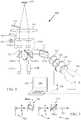
FIG. 4 , a colposcope 400 includes one or more objective lenses such aslens 402 configured to form an image of a specimen. Thelens 402 is coupled to abinocular microscope head 404 that includeseyepiece tubes respective eyepiece lenses binocular head 404 is configured to retain apolarization analysis module 405 so as to divert a portion of an optical flux propagating to theeyepiece tube 407A. Themodule 405 includesbeam splitters 409A, 409B that are configured so that an s-polarization input to thebeam splitter 409A would be a p-polarization at the beam splitter 409B. Similarly, thebeam splitters 409A, 409B are configured so that a p-polarization input to thebeam splitter 409A would be an s-polarization at the beam splitter 409B. Thebeam splitters 409A, 409B are nominally polarization insensitive plate or cube beam splitters, but typically exhibit some polarization dependence that can interfere with specimen analysis absent the polarization exchanging arrangement illustrated. - The
module 405 also includes avariable retarder 416 and apolarizer 418. Thevariable retarder 416 is conveniently a linear retarder that is switchable from 0 to ½ wave retardation. If thepolarizer 418 is a linear polarizer, an axis of thevariable retarder 416 is set to be about 45 degrees from the polarization axis of thelinear polarizer 418. Thevariable retarder 416 is thus situated so as to selectively transmit orthogonally polarized portions of an imaging light flux. ACCD 420 or other array detector is situated to receive images based on the selected polarization, and acontroller 424 includes amemory 422 for image storage. Images can be processed at thecontroller 424, and coupled to a display, or the image data can be communicated by a wired or wireless network for evaluation and viewing at a remote or local location. - In many examples, visible radiation is used for imaging so that images are directly viewable by a clinician. Because insertion of the
beam splitter 409A in the optical path associated with theeyepiece tube 407 tends to reduce image intensity, aneutral density filter 414 can be situated in an optical path associated with theeyepiece tube 406 so that the images are more balanced in intensity. In some examples, infrared radiation can be used for polarization analysis to better image below a tissue surface, and viewable visible images can be provided while infrared radiation is directed to thedetector 420. In this case, thebeam splitters 409A, 409B can be configured to transmit visible radiation. Is some cases (with or without different viewing and polarization analysis wavelengths), afocus adjuster 430 can be coupled to thecontroller 424 so that images at various distances above and below a specimen surface can be acquired, if desired. It can be advantageous to image below a specimen surface. For example, a skin surface can obscure structural details under investigation that are situated beneath the skin surface. Thecontroller 424 can vary focal depth while controlling thevariable retarder 416 so that images associated with orthogonal polarizations can be obtained at a plurality of depths. - Typically, the transmission axis of the
polarizer 418 is aligned so to correspond to an s- or p-polarization direction at the beam splitter 409B, but other orientations can be used. For convenience,FIG. 4 does not show other optical component such as narrow band or pass band filters, additional imaging elements for imaging at thearray detector 418. In addition, an illumination source is not shown, although usually provided so as to direct a polarized optical flux to the specimen. FIG. 5 and the following discussion are intended to provide a brief, general description of an exemplary computing environment in which the disclosed technology may be implemented. For example, images acquired as shown above can be processed and displayed. Although not required, the disclosed technology is described in the general context of computer-executable instructions, such as program modules, being executed by a personal computer (PC). Generally, program modules include routines, programs, objects, components, data structures, etc., that perform particular tasks or implement particular abstract data types. Moreover, the disclosed technology may be implemented with other computer system configurations, including hand-held devices, multiprocessor systems, microprocessor-based or programmable consumer electronics, network PCs, minicomputers, mainframe computers, and the like. The disclosed technology may also be practiced in distributed computing environments where tasks are performed by remote processing devices that are linked through a communications network. In a distributed computing environment, program modules may be located in both local and remote memory storage devices.- With reference to
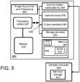
FIG. 5 , an exemplary system for implementing the disclosed technology includes a general purpose computing device in the form of an exemplaryconventional PC 500, including one ormore processing units 502, asystem memory 504, and asystem bus 506 that couples various system components including thesystem memory 504 to the one ormore processing units 502. Thesystem bus 506 may be any of several types of bus structures including a memory bus or memory controller, a peripheral bus, and a local bus using any of a variety of bus architectures. Theexemplary system memory 504 includes read only memory (ROM) 508 and random access memory (RAM) 510. A basic input/output system (BIOS) 512, containing the basic routines that help with the transfer of information between elements within thePC 500, is stored inROM 508. - The
exemplary PC 500 further includes one ormore storage devices 530 such as a hard disk drive for reading from and writing to a hard disk, a magnetic disk drive for reading from or writing to a removable magnetic disk, and an optical disk drive for reading from or writing to a removable optical disk (such as a CD-ROM or other optical media). Such storage devices can be connected to thesystem bus 506 by a hard disk drive interface, a magnetic disk drive interface, and an optical drive interface, respectively. The drives and their associated computer-readable media provide nonvolatile storage of computer-readable instructions, data structures, program modules, and other data for thePC 500. Other types of computer-readable media which can store data that is accessible by a PC, such as magnetic cassettes, flash memory cards, digital video disks, CDs, DVDs, RAMs, ROMs, and the like, may also be used in the exemplary operating environment. In some cases, aseparate storage device 555 can be provided for storage of computer-executable instructions for image acquisition and control. - A number of program modules may be stored in the
storage devices 530 including an operating system, one or more application programs, other program modules, and program data. A user may enter commands and information into thePC 500 through one ormore input devices 540 such as a keyboard and a pointing device such as a mouse. Other input devices may include a digital camera, microphone, joystick, game pad, satellite dish, scanner, or the like. These and other input devices are often connected to the one ormore processing units 502 through a serial port interface that is coupled to thesystem bus 506, but may be connected by other interfaces such as a parallel port, game port, or universal serial bus (USB). Amonitor 546 or other type of display device is also connected to thesystem bus 506 via an interface, such as a video adapter. Other peripheral output devices, such as speakers and printers (not shown), may be included. - The
PC 500 may operate in a networked environment using logical connections to one or more remote computers, such as aremote computer 560. In some examples, one or more network orcommunication connections 550 are included. Theremote computer 560 may be another PC, a server, a router, a network PC, or a peer device or other common network node, and typically includes many or all of the elements described above relative to thePC 500, although only amemory storage device 562 has been illustrated inFIG. 5 . Thepersonal computer 500 and/or theremote computer 560 can be connected to a logical a local area network (LAN) and a wide area network (WAN). Such networking environments are commonplace in offices, enterprise-wide computer networks, intranets, and the Internet. - When used in a LAN networking environment, the
PC 500 is connected to the LAN through a network interface. When used in a WAN networking environment, thePC 500 typically includes a modem or other means for establishing communications over the WAN, such as the Internet. In a networked environment, program modules depicted relative to thepersonal computer 500, or portions thereof, may be stored in the remote memory storage device or other locations on the LAN or WAN. The network connections shown are exemplary, and other means of establishing a communications link between the computers may be used. - The methods and apparatus described above can be applied to the assessment of a variety of specimens in applications other than colposcopy. For example, teeth and skin include structures that can be evaluated. For example, skin can exhibit fibrosis after radiation therapy, and this fibrosis can be detected as described above so that suitable therapy can be timely initiated.
- In view of the many possible embodiments to which the principles of the disclosure may be applied, it should be recognized that the illustrated embodiments are examples only and should not be taken as a limitation on the scope of the invention. For instance, various components of systems described herein may be combined in function and use. We claim as our invention all subject matter that comes within the scope of these claims. Alternatives specifically addressed in these sections are merely exemplary and do not constitute all possible alternatives to the embodiments described herein.

Claims (15)
- An apparatus, comprising:a binocular viewing head that defines a first imaging optical path and a second imaging optical path; anda polarization exchanging beam splitter pair (PEBSP) including a pair of non-polarizing beam splitters configured so that the first beam splitter reflects an s-component or a p-component of an incident optical flux and the second beam splitter reflects the s-component and the p-component of the reflected flux from the first beam splitter as a p-component or a s-component respectively,a variable waveplate (130), and a polarizer (132) situated in the second optical path and configured to selectively direct specimen imaging fluxes corresponding to a first polarization state and a second polarization state to an imaging optical system associated with the second optical path.
- The apparatus of claim 1, further comprising a first eyepiece (112A) and a second eyepiece (112B) situated on the first and second imaging optical paths, respectively, and configured to produce a viewable binocular image.
- The apparatus of claim 1 or 2, wherein the variable waveplate is a half waveplate that is variable so that the first and second polarization states are linear, orthogonal polarization states.
- The apparatus of claim 3, wherein the imaging optical system includes an array detector (140) configured to receive specimen images associated with the first polarization state and second polarization state.
- The apparatus of claim 4, further comprising an image processor configured to store the specimen images in a memory.
- The apparatus of claim 2, further comprising an optical attenuator (122) situated in the first imaging optical path and configured to compensate insertion loss in the second imaging optical path associated with the PEBSP.
- The apparatus of claim 5, wherein the optical attenuator is configured so that viewable images associated with the first imaging optical path and the second imaging optical path have substantially the same intensity, or further comprising an image processor configured to produce a correlation image based on specimen images associated with at least one of the first and second states of polarization.
- A method, comprising:obtaining at least a first specimen image and a second specimen image based on an optical flux received through a polarization exchanging beam splitter pair (PEBSP) including a pair of non-polarizing beam splitters configured so that the first beam splitter reflects an s-component or a p-component of an incident optical flux and the second beam splitter reflects the s-component and the p-component of the reflected flux from the first beam splitter as a p-component or a s-component respectively, wherein the first and second specimen images are associated with different states of polarization; andprocessing the first image and the second image to identify polarization dependent image portions and produce an associated polarization based images.
- The method of claim 8, further comprising displaying at least one of the polarization based images.
- The method of claim 8 or 9, wherein the first specimen image and the second specimen image are associated with orthogonal linear states of polarization.
- The method of claim 10, further comprising selectively detecting imaging optical flux portions associated with the orthogonal linear states of polarization to produce the specimen images, and preferably further comprising transmitting the imaging optical flux through a variable retarder (130) and a linear polarizer (132) to an image detector (140) so as to produce the selectively detected imaging optical flux portions, and more preferably wherein the variable retarder is selectively varied to produce substantially 0 or ½ wave retardance to produce the selectively detected imaging optical flux portions.
- The apparatus of claim 1, wherein:an optical flux source is configured to deliver an optical flux to a specimen in a selected state of polarization;an objective lens is configured to form an image of the specimen based on the delivered optical flux;the polarization exchanging beam splitter pair (PEBSP) is configured to receive the optical flux;the variable waveplate is situated to receive the optical flux from the PEBSP and deliver the optical flux to a polarizer;the imaging optical system comprises an image sensor situated to receive the
image; andan image processor is configured to store the received image as a recorded image. - The apparatus of claim 12, wherein the polarizer is a linear polarizer, or wherein the variable waveplate has an axis at 45 degrees with respect to the linear polarizer and is switchable to have retardation values of about 0 and about 180 degrees.
- The apparatus of claim 12 or 13, further comprising a processor configured to produce a correlation image of the specimen based on recorded images associated with at least one of the first and second retardation values of the variable retarder.
- The apparatus of claim 14, wherein the processor is configured to produce a correlation image of the specimen based on recorded images associated with the first and second retardation values of the variable retarder, or wherein the first and second retardation values differ by about one half wave, or wherein the correlation image is based on a Pearson's correlation analysis.
Applications Claiming Priority (2)
| Application Number | Priority Date | Filing Date | Title |
|---|---|---|---|
| US201261620295P | 2012-04-04 | 2012-04-04 | |
| PCT/US2013/035223WO2013152162A1 (en) | 2012-04-04 | 2013-04-04 | Polarimetric accessory for colposcope |
Publications (3)
| Publication Number | Publication Date |
|---|---|
| EP2833777A1 EP2833777A1 (en) | 2015-02-11 |
| EP2833777A4 EP2833777A4 (en) | 2015-11-18 |
| EP2833777B1true EP2833777B1 (en) | 2018-06-06 |
Family
ID=49301039
Family Applications (1)
| Application Number | Title | Priority Date | Filing Date |
|---|---|---|---|
| EP13772208.8AActiveEP2833777B1 (en) | 2012-04-04 | 2013-04-04 | Polarimetric accessory for colposcope |
Country Status (3)
| Country | Link |
|---|---|
| US (1) | US9801536B2 (en) |
| EP (1) | EP2833777B1 (en) |
| WO (1) | WO2013152162A1 (en) |
Families Citing this family (7)
| Publication number | Priority date | Publication date | Assignee | Title |
|---|---|---|---|---|
| DE202014102353U1 (en) | 2014-05-20 | 2014-05-27 | Borcad Cz S.R.O. | colposcope |
| US10706621B2 (en)* | 2015-11-30 | 2020-07-07 | Photopotech LLC | Systems and methods for processing image information |
| US10778877B2 (en) | 2015-11-30 | 2020-09-15 | Photopotech LLC | Image-capture device |
| US11217009B2 (en) | 2015-11-30 | 2022-01-04 | Photopotech LLC | Methods for collecting and processing image information to produce digital assets |
| US10114467B2 (en) | 2015-11-30 | 2018-10-30 | Photopotech LLC | Systems and methods for processing image information |
| US10306156B2 (en) | 2015-11-30 | 2019-05-28 | Photopotech LLC | Image-capture device |
| US11003048B1 (en)* | 2019-12-13 | 2021-05-11 | VG Technology Inc. | Polarized imaging apparatus for use with a mobile device |
Family Cites Families (12)
| Publication number | Priority date | Publication date | Assignee | Title |
|---|---|---|---|---|
| US6766184B2 (en) | 2000-03-28 | 2004-07-20 | Board Of Regents, The University Of Texas System | Methods and apparatus for diagnostic multispectral digital imaging |
| US7286227B2 (en)* | 2002-09-30 | 2007-10-23 | Carl Zeiss Meditec, Inc. | Method and system for removing the effects of corneal birefringence from a polarimetric image of the retina |
| US7612880B2 (en) | 2003-08-06 | 2009-11-03 | Arizona Board Of Regents On Behalf Of The University Of Arizona | Advanced polarization imaging method, apparatus, and computer program product for retinal imaging, liquid crystal testing, active remote sensing, and other applications |
| US7298496B2 (en)* | 2004-05-21 | 2007-11-20 | Zetetic Institute | Apparatus and methods for overlay, alignment mark, and critical dimension metrologies based on optical interferometry |
| JP4409384B2 (en)* | 2004-08-03 | 2010-02-03 | 株式会社トプコン | Optical image measuring device and optical image measuring method |
| US20060241495A1 (en)* | 2005-03-23 | 2006-10-26 | Eastman Kodak Company | Wound healing monitoring and treatment |
| DE602005004771T2 (en) | 2005-07-01 | 2009-03-05 | Ecole Polytechnique | Polarimetric electronic imaging system for a colposcopic device |
| US20090062662A1 (en) | 2007-08-27 | 2009-03-05 | Remicalm, Llc | Optical spectroscopic device for the identification of cervical cancer |
| DE102008024789A1 (en)* | 2008-05-21 | 2009-12-03 | Richard Wolf Gmbh | Stereo endoscope |
| CN102215732A (en)* | 2008-08-01 | 2011-10-12 | 国际科学技术医疗系统有限责任公司 | High resolution digital video colposcope with built-in polarized led illumination and computerized clinical data management system |
| TW201018888A (en)* | 2008-11-11 | 2010-05-16 | Ind Tech Res Inst | Phase retardance inspection instrument |
| JP5800308B2 (en) | 2010-07-20 | 2015-10-28 | 富士フイルム株式会社 | Polarized image measurement display system |
- 2013
- 2013-04-04EPEP13772208.8Apatent/EP2833777B1/enactiveActive
- 2013-04-04WOPCT/US2013/035223patent/WO2013152162A1/enactiveApplication Filing
- 2013-04-04USUS14/390,354patent/US9801536B2/enactiveActive
Non-Patent Citations (1)
| Title |
|---|
| None* |
Also Published As
| Publication number | Publication date |
|---|---|
| EP2833777A4 (en) | 2015-11-18 |
| US9801536B2 (en) | 2017-10-31 |
| WO2013152162A1 (en) | 2013-10-10 |
| EP2833777A1 (en) | 2015-02-11 |
| US20150112136A1 (en) | 2015-04-23 |
Similar Documents
| Publication | Publication Date | Title |
|---|---|---|
| EP2833777B1 (en) | Polarimetric accessory for colposcope | |
| Qi et al. | Mueller polarimetric imaging for surgical and diagnostic applications: a review | |
| US7612880B2 (en) | Advanced polarization imaging method, apparatus, and computer program product for retinal imaging, liquid crystal testing, active remote sensing, and other applications | |
| Qi et al. | Narrow band 3× 3 Mueller polarimetric endoscopy | |
| EP0891151B1 (en) | Non-invasive measurement of optically active compounds | |
| US8214024B2 (en) | Electronic polarimetric imaging system for a colposcopy device and an adapter housing | |
| CA2321842C (en) | Video imaging of superficial biological tissue layers using polarized light | |
| JP2004028970A (en) | Polarization-sensitive optical spectrum interference coherence tomography apparatus and method for measuring polarization information inside sample using the apparatus | |
| EP3864459B1 (en) | Method and apparatus for measuring depth-resolved tissue birefringence using single input state polarization sensitive optical coherence tomography | |
| US20200092534A1 (en) | Three-dimensional image reconstruction using multi-layer data acquisition | |
| JP2008519264A (en) | System and method for performing Jones matrix based analysis to measure unpolarized polarization parameters using polarization sensitive optical coherence tomography | |
| US7079247B2 (en) | Instantaneous polarization measurement system and method | |
| US8223322B2 (en) | Visual appearance measurement method and system for randomly and regularly arranged birefringent fibers | |
| JP5341285B1 (en) | Polarized light observation equipment | |
| JP2009213649A (en) | Endoscope observation system | |
| US20110075153A1 (en) | Compact isolated analysis system | |
| KR102741022B1 (en) | Opotical system using polirization characteristic | |
| US20090244537A1 (en) | Optical system, method, and computer readable medium | |
| US7360897B2 (en) | Fundus examination apparatus | |
| WO2023105242A1 (en) | Polarimetric endoscopy | |
| Zhu et al. | Experimental and theoretical evaluation of rotating orthogonal polarization imaging | |
| Collins et al. | Design, construction and calibration of the Galway astronomical Stokes polarimeter (GASP) | |
| Pierangelo | In vivo imaging of uterine cervix with a Mueller polarimetric colposcope | |
| Louie et al. | Achieving Snapshot Imaging of the Spatial Stokes Vector Distribution of Polarization Speckle in Turbid Optical Phantoms and in Vivo Tissues | |
| EP1642099A1 (en) | Instantaneous polarization measurement system and method |
Legal Events
| Date | Code | Title | Description |
|---|---|---|---|
| PUAI | Public reference made under article 153(3) epc to a published international application that has entered the european phase | Free format text:ORIGINAL CODE: 0009012 | |
| 17P | Request for examination filed | Effective date:20140910 | |
| AK | Designated contracting states | Kind code of ref document:A1 Designated state(s):AL AT BE BG CH CY CZ DE DK EE ES FI FR GB GR HR HU IE IS IT LI LT LU LV MC MK MT NL NO PL PT RO RS SE SI SK SM TR | |
| AX | Request for extension of the european patent | Extension state:BA ME | |
| DAX | Request for extension of the european patent (deleted) | ||
| RA4 | Supplementary search report drawn up and despatched (corrected) | Effective date:20151019 | |
| RIC1 | Information provided on ipc code assigned before grant | Ipc:A61B 1/303 20060101AFI20151013BHEP Ipc:G01J 3/02 20060101ALI20151013BHEP | |
| RIN1 | Information on inventor provided before grant (corrected) | Inventor name:HASSAN, MOINUDDIN Inventor name:CHERNOMORDIK, VICTOR Inventor name:SVIRIDOV, ALEXANDER Inventor name:BOCCARA, ALBERT, C. Inventor name:SMITH, PAUL, D. Inventor name:GANDJBAKHCHE, AMIR Inventor name:ULISSI, ZACHARY | |
| GRAP | Despatch of communication of intention to grant a patent | Free format text:ORIGINAL CODE: EPIDOSNIGR1 | |
| STAA | Information on the status of an ep patent application or granted ep patent | Free format text:STATUS: GRANT OF PATENT IS INTENDED | |
| INTG | Intention to grant announced | Effective date:20171031 | |
| RIN1 | Information on inventor provided before grant (corrected) | Inventor name:HASSAN, MOINUDDIN Inventor name:BOCCARA, ALBERT, C. Inventor name:CHERNOMORDIK, VICTOR Inventor name:GANDJBAKHCHE, AMIR Inventor name:ULISSI, ZACHARY Inventor name:SMITH, PAUL, D. Inventor name:SVIRIDOV, ALEXANDER | |
| GRAJ | Information related to disapproval of communication of intention to grant by the applicant or resumption of examination proceedings by the epo deleted | Free format text:ORIGINAL CODE: EPIDOSDIGR1 | |
| STAA | Information on the status of an ep patent application or granted ep patent | Free format text:STATUS: REQUEST FOR EXAMINATION WAS MADE | |
| GRAR | Information related to intention to grant a patent recorded | Free format text:ORIGINAL CODE: EPIDOSNIGR71 | |
| GRAS | Grant fee paid | Free format text:ORIGINAL CODE: EPIDOSNIGR3 | |
| STAA | Information on the status of an ep patent application or granted ep patent | Free format text:STATUS: GRANT OF PATENT IS INTENDED | |
| INTC | Intention to grant announced (deleted) | ||
| INTG | Intention to grant announced | Effective date:20180308 | |
| GRAA | (expected) grant | Free format text:ORIGINAL CODE: 0009210 | |
| STAA | Information on the status of an ep patent application or granted ep patent | Free format text:STATUS: THE PATENT HAS BEEN GRANTED | |
| AK | Designated contracting states | Kind code of ref document:B1 Designated state(s):AL AT BE BG CH CY CZ DE DK EE ES FI FR GB GR HR HU IE IS IT LI LT LU LV MC MK MT NL NO PL PT RO RS SE SI SK SM TR | |
| REG | Reference to a national code | Ref country code:GB Ref legal event code:FG4D | |
| REG | Reference to a national code | Ref country code:CH Ref legal event code:EP Ref country code:AT Ref legal event code:REF Ref document number:1005148 Country of ref document:AT Kind code of ref document:T Effective date:20180615 | |
| REG | Reference to a national code | Ref country code:IE Ref legal event code:FG4D | |
| REG | Reference to a national code | Ref country code:DE Ref legal event code:R096 Ref document number:602013038597 Country of ref document:DE | |
| REG | Reference to a national code | Ref country code:NL Ref legal event code:MP Effective date:20180606 | |
| REG | Reference to a national code | Ref country code:LT Ref legal event code:MG4D | |
| PG25 | Lapsed in a contracting state [announced via postgrant information from national office to epo] | Ref country code:ES Free format text:LAPSE BECAUSE OF FAILURE TO SUBMIT A TRANSLATION OF THE DESCRIPTION OR TO PAY THE FEE WITHIN THE PRESCRIBED TIME-LIMIT Effective date:20180606 Ref country code:CY Free format text:LAPSE BECAUSE OF FAILURE TO SUBMIT A TRANSLATION OF THE DESCRIPTION OR TO PAY THE FEE WITHIN THE PRESCRIBED TIME-LIMIT Effective date:20180606 Ref country code:LT Free format text:LAPSE BECAUSE OF FAILURE TO SUBMIT A TRANSLATION OF THE DESCRIPTION OR TO PAY THE FEE WITHIN THE PRESCRIBED TIME-LIMIT Effective date:20180606 Ref country code:BG Free format text:LAPSE BECAUSE OF FAILURE TO SUBMIT A TRANSLATION OF THE DESCRIPTION OR TO PAY THE FEE WITHIN THE PRESCRIBED TIME-LIMIT Effective date:20180906 Ref country code:FI Free format text:LAPSE BECAUSE OF FAILURE TO SUBMIT A TRANSLATION OF THE DESCRIPTION OR TO PAY THE FEE WITHIN THE PRESCRIBED TIME-LIMIT Effective date:20180606 Ref country code:SE Free format text:LAPSE BECAUSE OF FAILURE TO SUBMIT A TRANSLATION OF THE DESCRIPTION OR TO PAY THE FEE WITHIN THE PRESCRIBED TIME-LIMIT Effective date:20180606 Ref country code:NO Free format text:LAPSE BECAUSE OF FAILURE TO SUBMIT A TRANSLATION OF THE DESCRIPTION OR TO PAY THE FEE WITHIN THE PRESCRIBED TIME-LIMIT Effective date:20180906 | |
| PG25 | Lapsed in a contracting state [announced via postgrant information from national office to epo] | Ref country code:HR Free format text:LAPSE BECAUSE OF FAILURE TO SUBMIT A TRANSLATION OF THE DESCRIPTION OR TO PAY THE FEE WITHIN THE PRESCRIBED TIME-LIMIT Effective date:20180606 Ref country code:GR Free format text:LAPSE BECAUSE OF FAILURE TO SUBMIT A TRANSLATION OF THE DESCRIPTION OR TO PAY THE FEE WITHIN THE PRESCRIBED TIME-LIMIT Effective date:20180907 Ref country code:LV Free format text:LAPSE BECAUSE OF FAILURE TO SUBMIT A TRANSLATION OF THE DESCRIPTION OR TO PAY THE FEE WITHIN THE PRESCRIBED TIME-LIMIT Effective date:20180606 Ref country code:RS Free format text:LAPSE BECAUSE OF FAILURE TO SUBMIT A TRANSLATION OF THE DESCRIPTION OR TO PAY THE FEE WITHIN THE PRESCRIBED TIME-LIMIT Effective date:20180606 | |
| REG | Reference to a national code | Ref country code:AT Ref legal event code:MK05 Ref document number:1005148 Country of ref document:AT Kind code of ref document:T Effective date:20180606 | |
| PG25 | Lapsed in a contracting state [announced via postgrant information from national office to epo] | Ref country code:NL Free format text:LAPSE BECAUSE OF FAILURE TO SUBMIT A TRANSLATION OF THE DESCRIPTION OR TO PAY THE FEE WITHIN THE PRESCRIBED TIME-LIMIT Effective date:20180606 | |
| PG25 | Lapsed in a contracting state [announced via postgrant information from national office to epo] | Ref country code:CZ Free format text:LAPSE BECAUSE OF FAILURE TO SUBMIT A TRANSLATION OF THE DESCRIPTION OR TO PAY THE FEE WITHIN THE PRESCRIBED TIME-LIMIT Effective date:20180606 Ref country code:RO Free format text:LAPSE BECAUSE OF FAILURE TO SUBMIT A TRANSLATION OF THE DESCRIPTION OR TO PAY THE FEE WITHIN THE PRESCRIBED TIME-LIMIT Effective date:20180606 Ref country code:SK Free format text:LAPSE BECAUSE OF FAILURE TO SUBMIT A TRANSLATION OF THE DESCRIPTION OR TO PAY THE FEE WITHIN THE PRESCRIBED TIME-LIMIT Effective date:20180606 Ref country code:PL Free format text:LAPSE BECAUSE OF FAILURE TO SUBMIT A TRANSLATION OF THE DESCRIPTION OR TO PAY THE FEE WITHIN THE PRESCRIBED TIME-LIMIT Effective date:20180606 Ref country code:EE Free format text:LAPSE BECAUSE OF FAILURE TO SUBMIT A TRANSLATION OF THE DESCRIPTION OR TO PAY THE FEE WITHIN THE PRESCRIBED TIME-LIMIT Effective date:20180606 Ref country code:AT Free format text:LAPSE BECAUSE OF FAILURE TO SUBMIT A TRANSLATION OF THE DESCRIPTION OR TO PAY THE FEE WITHIN THE PRESCRIBED TIME-LIMIT Effective date:20180606 Ref country code:IS Free format text:LAPSE BECAUSE OF FAILURE TO SUBMIT A TRANSLATION OF THE DESCRIPTION OR TO PAY THE FEE WITHIN THE PRESCRIBED TIME-LIMIT Effective date:20181006 | |
| PG25 | Lapsed in a contracting state [announced via postgrant information from national office to epo] | Ref country code:IT Free format text:LAPSE BECAUSE OF FAILURE TO SUBMIT A TRANSLATION OF THE DESCRIPTION OR TO PAY THE FEE WITHIN THE PRESCRIBED TIME-LIMIT Effective date:20180606 Ref country code:SM Free format text:LAPSE BECAUSE OF FAILURE TO SUBMIT A TRANSLATION OF THE DESCRIPTION OR TO PAY THE FEE WITHIN THE PRESCRIBED TIME-LIMIT Effective date:20180606 | |
| REG | Reference to a national code | Ref country code:DE Ref legal event code:R097 Ref document number:602013038597 Country of ref document:DE | |
| PLBE | No opposition filed within time limit | Free format text:ORIGINAL CODE: 0009261 | |
| STAA | Information on the status of an ep patent application or granted ep patent | Free format text:STATUS: NO OPPOSITION FILED WITHIN TIME LIMIT | |
| 26N | No opposition filed | Effective date:20190307 | |
| PG25 | Lapsed in a contracting state [announced via postgrant information from national office to epo] | Ref country code:SI Free format text:LAPSE BECAUSE OF FAILURE TO SUBMIT A TRANSLATION OF THE DESCRIPTION OR TO PAY THE FEE WITHIN THE PRESCRIBED TIME-LIMIT Effective date:20180606 Ref country code:DK Free format text:LAPSE BECAUSE OF FAILURE TO SUBMIT A TRANSLATION OF THE DESCRIPTION OR TO PAY THE FEE WITHIN THE PRESCRIBED TIME-LIMIT Effective date:20180606 | |
| PG25 | Lapsed in a contracting state [announced via postgrant information from national office to epo] | Ref country code:AL Free format text:LAPSE BECAUSE OF FAILURE TO SUBMIT A TRANSLATION OF THE DESCRIPTION OR TO PAY THE FEE WITHIN THE PRESCRIBED TIME-LIMIT Effective date:20180606 | |
| REG | Reference to a national code | Ref country code:CH Ref legal event code:PL | |
| REG | Reference to a national code | Ref country code:BE Ref legal event code:MM Effective date:20190430 | |
| PG25 | Lapsed in a contracting state [announced via postgrant information from national office to epo] | Ref country code:MC Free format text:LAPSE BECAUSE OF FAILURE TO SUBMIT A TRANSLATION OF THE DESCRIPTION OR TO PAY THE FEE WITHIN THE PRESCRIBED TIME-LIMIT Effective date:20180606 Ref country code:LU Free format text:LAPSE BECAUSE OF NON-PAYMENT OF DUE FEES Effective date:20190404 | |
| PG25 | Lapsed in a contracting state [announced via postgrant information from national office to epo] | Ref country code:CH Free format text:LAPSE BECAUSE OF NON-PAYMENT OF DUE FEES Effective date:20190430 Ref country code:LI Free format text:LAPSE BECAUSE OF NON-PAYMENT OF DUE FEES Effective date:20190430 | |
| PG25 | Lapsed in a contracting state [announced via postgrant information from national office to epo] | Ref country code:BE Free format text:LAPSE BECAUSE OF NON-PAYMENT OF DUE FEES Effective date:20190430 | |
| PG25 | Lapsed in a contracting state [announced via postgrant information from national office to epo] | Ref country code:TR Free format text:LAPSE BECAUSE OF FAILURE TO SUBMIT A TRANSLATION OF THE DESCRIPTION OR TO PAY THE FEE WITHIN THE PRESCRIBED TIME-LIMIT Effective date:20180606 | |
| PG25 | Lapsed in a contracting state [announced via postgrant information from national office to epo] | Ref country code:IE Free format text:LAPSE BECAUSE OF NON-PAYMENT OF DUE FEES Effective date:20190404 | |
| PG25 | Lapsed in a contracting state [announced via postgrant information from national office to epo] | Ref country code:PT Free format text:LAPSE BECAUSE OF FAILURE TO SUBMIT A TRANSLATION OF THE DESCRIPTION OR TO PAY THE FEE WITHIN THE PRESCRIBED TIME-LIMIT Effective date:20181008 | |
| PG25 | Lapsed in a contracting state [announced via postgrant information from national office to epo] | Ref country code:MT Free format text:LAPSE BECAUSE OF FAILURE TO SUBMIT A TRANSLATION OF THE DESCRIPTION OR TO PAY THE FEE WITHIN THE PRESCRIBED TIME-LIMIT Effective date:20180606 Ref country code:HU Free format text:LAPSE BECAUSE OF FAILURE TO SUBMIT A TRANSLATION OF THE DESCRIPTION OR TO PAY THE FEE WITHIN THE PRESCRIBED TIME-LIMIT; INVALID AB INITIO Effective date:20130404 | |
| PG25 | Lapsed in a contracting state [announced via postgrant information from national office to epo] | Ref country code:MK Free format text:LAPSE BECAUSE OF FAILURE TO SUBMIT A TRANSLATION OF THE DESCRIPTION OR TO PAY THE FEE WITHIN THE PRESCRIBED TIME-LIMIT Effective date:20180606 | |
| P01 | Opt-out of the competence of the unified patent court (upc) registered | Effective date:20230512 | |
| PGFP | Annual fee paid to national office [announced via postgrant information from national office to epo] | Ref country code:DE Payment date:20250429 Year of fee payment:13 | |
| PGFP | Annual fee paid to national office [announced via postgrant information from national office to epo] | Ref country code:GB Payment date:20250428 Year of fee payment:13 | |
| PGFP | Annual fee paid to national office [announced via postgrant information from national office to epo] | Ref country code:FR Payment date:20250425 Year of fee payment:13 |