EP2832309A1 - Implant for bones or vertebrae with self-constrained flexibility - Google Patents
Implant for bones or vertebrae with self-constrained flexibilityDownload PDFInfo
- Publication number
- EP2832309A1 EP2832309A1EP13190622.4AEP13190622AEP2832309A1EP 2832309 A1EP2832309 A1EP 2832309A1EP 13190622 AEP13190622 AEP 13190622AEP 2832309 A1EP2832309 A1EP 2832309A1
- Authority
- EP
- European Patent Office
- Prior art keywords
- implant
- cavity
- slit
- width
- longitudinal direction
- Prior art date
- Legal status (The legal status is an assumption and is not a legal conclusion. Google has not performed a legal analysis and makes no representation as to the accuracy of the status listed.)
- Granted
Links
- 210000000988bone and boneAnatomy0.000titleclaimsabstractdescription134
- 239000007943implantSubstances0.000titleclaimsabstractdescription130
- 230000006641stabilisationEffects0.000claimsabstractdescription18
- 238000011105stabilizationMethods0.000claimsabstractdescription18
- 239000007787solidSubstances0.000claimsabstractdescription16
- 238000004519manufacturing processMethods0.000claimsdescription21
- 239000000654additiveSubstances0.000claimsdescription11
- 230000000996additive effectEffects0.000claimsdescription11
- 230000006835compressionEffects0.000claimsdescription10
- 238000007906compressionMethods0.000claimsdescription10
- 238000000110selective laser sinteringMethods0.000claimsdescription9
- 238000000149argon plasma sinteringMethods0.000claimsdescription2
- 238000013461designMethods0.000description25
- 238000005452bendingMethods0.000description14
- 238000012986modificationMethods0.000description14
- 230000004048modificationEffects0.000description14
- 238000005520cutting processMethods0.000description9
- 230000033001locomotionEffects0.000description7
- 239000000463materialSubstances0.000description6
- 239000004696Poly ether ether ketoneSubstances0.000description3
- 238000004873anchoringMethods0.000description3
- 238000002844meltingMethods0.000description3
- 230000008018meltingEffects0.000description3
- 229910052751metalInorganic materials0.000description3
- 239000002184metalSubstances0.000description3
- 239000004033plasticSubstances0.000description3
- 229920002530polyetherether ketonePolymers0.000description3
- 239000000843powderSubstances0.000description3
- RTAQQCXQSZGOHL-UHFFFAOYSA-NTitaniumChemical compound[Ti]RTAQQCXQSZGOHL-UHFFFAOYSA-N0.000description2
- 229910045601alloyInorganic materials0.000description2
- 239000000956alloySubstances0.000description2
- 238000011161developmentMethods0.000description2
- 230000018109developmental processEffects0.000description2
- 230000000694effectsEffects0.000description2
- 238000009760electrical discharge machiningMethods0.000description2
- 229910001092metal group alloyInorganic materials0.000description2
- 238000000034methodMethods0.000description2
- 229910001000nickel titaniumInorganic materials0.000description2
- 239000010935stainless steelSubstances0.000description2
- 229910001220stainless steelInorganic materials0.000description2
- 239000002775capsuleSubstances0.000description1
- 238000007796conventional methodMethods0.000description1
- 238000005336crackingMethods0.000description1
- 230000003247decreasing effectEffects0.000description1
- 230000001419dependent effectEffects0.000description1
- 238000006073displacement reactionMethods0.000description1
- 238000010894electron beam technologyMethods0.000description1
- 238000005516engineering processMethods0.000description1
- 230000001747exhibiting effectEffects0.000description1
- 210000002758humerusAnatomy0.000description1
- 230000001788irregularEffects0.000description1
- 150000002739metalsChemical class0.000description1
- HLXZNVUGXRDIFK-UHFFFAOYSA-Nnickel titaniumChemical compound[Ti].[Ti].[Ti].[Ti].[Ti].[Ti].[Ti].[Ti].[Ti].[Ti].[Ti].[Ni].[Ni].[Ni].[Ni].[Ni].[Ni].[Ni].[Ni].[Ni].[Ni].[Ni].[Ni].[Ni].[Ni]HLXZNVUGXRDIFK-UHFFFAOYSA-N0.000description1
- 238000009877renderingMethods0.000description1
- 238000009987spinningMethods0.000description1
- 239000010936titaniumSubstances0.000description1
- 229910052719titaniumInorganic materials0.000description1
Images


Classifications
- A—HUMAN NECESSITIES
- A61—MEDICAL OR VETERINARY SCIENCE; HYGIENE
- A61B—DIAGNOSIS; SURGERY; IDENTIFICATION
- A61B17/00—Surgical instruments, devices or methods
- A61B17/56—Surgical instruments or methods for treatment of bones or joints; Devices specially adapted therefor
- A61B17/58—Surgical instruments or methods for treatment of bones or joints; Devices specially adapted therefor for osteosynthesis, e.g. bone plates, screws or setting implements
- A61B17/68—Internal fixation devices, including fasteners and spinal fixators, even if a part thereof projects from the skin
- A61B17/70—Spinal positioners or stabilisers, e.g. stabilisers comprising fluid filler in an implant
- A61B17/7001—Screws or hooks combined with longitudinal elements which do not contact vertebrae
- A61B17/7002—Longitudinal elements, e.g. rods
- A61B17/7019—Longitudinal elements having flexible parts, or parts connected together, such that after implantation the elements can move relative to each other
- A61B17/7026—Longitudinal elements having flexible parts, or parts connected together, such that after implantation the elements can move relative to each other with a part that is flexible due to its form
- A61B17/7028—Longitudinal elements having flexible parts, or parts connected together, such that after implantation the elements can move relative to each other with a part that is flexible due to its form the flexible part being a coil spring
- A—HUMAN NECESSITIES
- A61—MEDICAL OR VETERINARY SCIENCE; HYGIENE
- A61B—DIAGNOSIS; SURGERY; IDENTIFICATION
- A61B17/00—Surgical instruments, devices or methods
- A61B17/56—Surgical instruments or methods for treatment of bones or joints; Devices specially adapted therefor
- A61B17/58—Surgical instruments or methods for treatment of bones or joints; Devices specially adapted therefor for osteosynthesis, e.g. bone plates, screws or setting implements
- A61B17/68—Internal fixation devices, including fasteners and spinal fixators, even if a part thereof projects from the skin
- A61B17/70—Spinal positioners or stabilisers, e.g. stabilisers comprising fluid filler in an implant
- A61B17/7001—Screws or hooks combined with longitudinal elements which do not contact vertebrae
- A61B17/7002—Longitudinal elements, e.g. rods
- A61B17/7019—Longitudinal elements having flexible parts, or parts connected together, such that after implantation the elements can move relative to each other
- A61B17/7026—Longitudinal elements having flexible parts, or parts connected together, such that after implantation the elements can move relative to each other with a part that is flexible due to its form
- A—HUMAN NECESSITIES
- A61—MEDICAL OR VETERINARY SCIENCE; HYGIENE
- A61B—DIAGNOSIS; SURGERY; IDENTIFICATION
- A61B17/00—Surgical instruments, devices or methods
- A61B17/56—Surgical instruments or methods for treatment of bones or joints; Devices specially adapted therefor
- A61B17/58—Surgical instruments or methods for treatment of bones or joints; Devices specially adapted therefor for osteosynthesis, e.g. bone plates, screws or setting implements
- A61B17/68—Internal fixation devices, including fasteners and spinal fixators, even if a part thereof projects from the skin
- A61B17/70—Spinal positioners or stabilisers, e.g. stabilisers comprising fluid filler in an implant
- A61B17/7001—Screws or hooks combined with longitudinal elements which do not contact vertebrae
- A61B17/7002—Longitudinal elements, e.g. rods
- A61B17/7019—Longitudinal elements having flexible parts, or parts connected together, such that after implantation the elements can move relative to each other
- A61B17/7031—Longitudinal elements having flexible parts, or parts connected together, such that after implantation the elements can move relative to each other made wholly or partly of flexible material
- A—HUMAN NECESSITIES
- A61—MEDICAL OR VETERINARY SCIENCE; HYGIENE
- A61B—DIAGNOSIS; SURGERY; IDENTIFICATION
- A61B17/00—Surgical instruments, devices or methods
- A61B17/56—Surgical instruments or methods for treatment of bones or joints; Devices specially adapted therefor
- A61B17/58—Surgical instruments or methods for treatment of bones or joints; Devices specially adapted therefor for osteosynthesis, e.g. bone plates, screws or setting implements
- A61B17/68—Internal fixation devices, including fasteners and spinal fixators, even if a part thereof projects from the skin
- A61B17/70—Spinal positioners or stabilisers, e.g. stabilisers comprising fluid filler in an implant
- A61B17/7059—Cortical plates
- A—HUMAN NECESSITIES
- A61—MEDICAL OR VETERINARY SCIENCE; HYGIENE
- A61B—DIAGNOSIS; SURGERY; IDENTIFICATION
- A61B17/00—Surgical instruments, devices or methods
- A61B17/56—Surgical instruments or methods for treatment of bones or joints; Devices specially adapted therefor
- A61B17/58—Surgical instruments or methods for treatment of bones or joints; Devices specially adapted therefor for osteosynthesis, e.g. bone plates, screws or setting implements
- A61B17/68—Internal fixation devices, including fasteners and spinal fixators, even if a part thereof projects from the skin
- A61B17/80—Cortical plates, i.e. bone plates; Instruments for holding or positioning cortical plates, or for compressing bones attached to cortical plates
- A61B17/8085—Cortical plates, i.e. bone plates; Instruments for holding or positioning cortical plates, or for compressing bones attached to cortical plates with pliable or malleable elements or having a mesh-like structure, e.g. small strips
- A—HUMAN NECESSITIES
- A61—MEDICAL OR VETERINARY SCIENCE; HYGIENE
- A61B—DIAGNOSIS; SURGERY; IDENTIFICATION
- A61B17/00—Surgical instruments, devices or methods
- A61B17/56—Surgical instruments or methods for treatment of bones or joints; Devices specially adapted therefor
- A61B17/58—Surgical instruments or methods for treatment of bones or joints; Devices specially adapted therefor for osteosynthesis, e.g. bone plates, screws or setting implements
- A61B17/68—Internal fixation devices, including fasteners and spinal fixators, even if a part thereof projects from the skin
- A61B17/84—Fasteners therefor or fasteners being internal fixation devices
- A61B17/86—Pins or screws or threaded wires; nuts therefor
- A61B17/8625—Shanks, i.e. parts contacting bone tissue
- A—HUMAN NECESSITIES
- A61—MEDICAL OR VETERINARY SCIENCE; HYGIENE
- A61B—DIAGNOSIS; SURGERY; IDENTIFICATION
- A61B17/00—Surgical instruments, devices or methods
- A61B17/56—Surgical instruments or methods for treatment of bones or joints; Devices specially adapted therefor
- A61B17/58—Surgical instruments or methods for treatment of bones or joints; Devices specially adapted therefor for osteosynthesis, e.g. bone plates, screws or setting implements
- A61B17/68—Internal fixation devices, including fasteners and spinal fixators, even if a part thereof projects from the skin
- A61B17/84—Fasteners therefor or fasteners being internal fixation devices
- A61B17/86—Pins or screws or threaded wires; nuts therefor
- A61B17/866—Material or manufacture
- A—HUMAN NECESSITIES
- A61—MEDICAL OR VETERINARY SCIENCE; HYGIENE
- A61B—DIAGNOSIS; SURGERY; IDENTIFICATION
- A61B17/00—Surgical instruments, devices or methods
- A61B17/56—Surgical instruments or methods for treatment of bones or joints; Devices specially adapted therefor
- A61B17/58—Surgical instruments or methods for treatment of bones or joints; Devices specially adapted therefor for osteosynthesis, e.g. bone plates, screws or setting implements
- A61B17/68—Internal fixation devices, including fasteners and spinal fixators, even if a part thereof projects from the skin
- A61B17/84—Fasteners therefor or fasteners being internal fixation devices
- A61B17/86—Pins or screws or threaded wires; nuts therefor
- A61B17/869—Pins or screws or threaded wires; nuts therefor characterised by an open form, e.g. wire helix
- B—PERFORMING OPERATIONS; TRANSPORTING
- B22—CASTING; POWDER METALLURGY
- B22F—WORKING METALLIC POWDER; MANUFACTURE OF ARTICLES FROM METALLIC POWDER; MAKING METALLIC POWDER; APPARATUS OR DEVICES SPECIALLY ADAPTED FOR METALLIC POWDER
- B22F10/00—Additive manufacturing of workpieces or articles from metallic powder
- B22F10/20—Direct sintering or melting
- B—PERFORMING OPERATIONS; TRANSPORTING
- B22—CASTING; POWDER METALLURGY
- B22F—WORKING METALLIC POWDER; MANUFACTURE OF ARTICLES FROM METALLIC POWDER; MAKING METALLIC POWDER; APPARATUS OR DEVICES SPECIALLY ADAPTED FOR METALLIC POWDER
- B22F3/00—Manufacture of workpieces or articles from metallic powder characterised by the manner of compacting or sintering; Apparatus specially adapted therefor ; Presses and furnaces
- B22F3/24—After-treatment of workpieces or articles
- B—PERFORMING OPERATIONS; TRANSPORTING
- B22—CASTING; POWDER METALLURGY
- B22F—WORKING METALLIC POWDER; MANUFACTURE OF ARTICLES FROM METALLIC POWDER; MAKING METALLIC POWDER; APPARATUS OR DEVICES SPECIALLY ADAPTED FOR METALLIC POWDER
- B22F5/00—Manufacture of workpieces or articles from metallic powder characterised by the special shape of the product
- B22F5/10—Manufacture of workpieces or articles from metallic powder characterised by the special shape of the product of articles with cavities or holes, not otherwise provided for in the preceding subgroups
- B22F5/106—Tube or ring forms
- B—PERFORMING OPERATIONS; TRANSPORTING
- B29—WORKING OF PLASTICS; WORKING OF SUBSTANCES IN A PLASTIC STATE IN GENERAL
- B29C—SHAPING OR JOINING OF PLASTICS; SHAPING OF MATERIAL IN A PLASTIC STATE, NOT OTHERWISE PROVIDED FOR; AFTER-TREATMENT OF THE SHAPED PRODUCTS, e.g. REPAIRING
- B29C64/00—Additive manufacturing, i.e. manufacturing of three-dimensional [3D] objects by additive deposition, additive agglomeration or additive layering, e.g. by 3D printing, stereolithography or selective laser sintering
- B29C64/10—Processes of additive manufacturing
- B29C64/141—Processes of additive manufacturing using only solid materials
- B29C64/153—Processes of additive manufacturing using only solid materials using layers of powder being selectively joined, e.g. by selective laser sintering or melting
- A—HUMAN NECESSITIES
- A61—MEDICAL OR VETERINARY SCIENCE; HYGIENE
- A61B—DIAGNOSIS; SURGERY; IDENTIFICATION
- A61B17/00—Surgical instruments, devices or methods
- A61B2017/00831—Material properties
- A61B2017/00862—Material properties elastic or resilient
- B—PERFORMING OPERATIONS; TRANSPORTING
- B22—CASTING; POWDER METALLURGY
- B22F—WORKING METALLIC POWDER; MANUFACTURE OF ARTICLES FROM METALLIC POWDER; MAKING METALLIC POWDER; APPARATUS OR DEVICES SPECIALLY ADAPTED FOR METALLIC POWDER
- B22F10/00—Additive manufacturing of workpieces or articles from metallic powder
- B22F10/20—Direct sintering or melting
- B22F10/28—Powder bed fusion, e.g. selective laser melting [SLM] or electron beam melting [EBM]
- B—PERFORMING OPERATIONS; TRANSPORTING
- B22—CASTING; POWDER METALLURGY
- B22F—WORKING METALLIC POWDER; MANUFACTURE OF ARTICLES FROM METALLIC POWDER; MAKING METALLIC POWDER; APPARATUS OR DEVICES SPECIALLY ADAPTED FOR METALLIC POWDER
- B22F3/00—Manufacture of workpieces or articles from metallic powder characterised by the manner of compacting or sintering; Apparatus specially adapted therefor ; Presses and furnaces
- B22F3/24—After-treatment of workpieces or articles
- B22F2003/245—Making recesses, grooves etc on the surface by removing material
- B—PERFORMING OPERATIONS; TRANSPORTING
- B22—CASTING; POWDER METALLURGY
- B22F—WORKING METALLIC POWDER; MANUFACTURE OF ARTICLES FROM METALLIC POWDER; MAKING METALLIC POWDER; APPARATUS OR DEVICES SPECIALLY ADAPTED FOR METALLIC POWDER
- B22F5/00—Manufacture of workpieces or articles from metallic powder characterised by the special shape of the product
- B22F2005/004—Article comprising helical form elements
- B—PERFORMING OPERATIONS; TRANSPORTING
- B29—WORKING OF PLASTICS; WORKING OF SUBSTANCES IN A PLASTIC STATE IN GENERAL
- B29K—INDEXING SCHEME ASSOCIATED WITH SUBCLASSES B29B, B29C OR B29D, RELATING TO MOULDING MATERIALS OR TO MATERIALS FOR MOULDS, REINFORCEMENTS, FILLERS OR PREFORMED PARTS, e.g. INSERTS
- B29K2071/00—Use of polyethers, e.g. PEEK, i.e. polyether-etherketone or PEK, i.e. polyetherketone or derivatives thereof, as moulding material
- B—PERFORMING OPERATIONS; TRANSPORTING
- B29—WORKING OF PLASTICS; WORKING OF SUBSTANCES IN A PLASTIC STATE IN GENERAL
- B29K—INDEXING SCHEME ASSOCIATED WITH SUBCLASSES B29B, B29C OR B29D, RELATING TO MOULDING MATERIALS OR TO MATERIALS FOR MOULDS, REINFORCEMENTS, FILLERS OR PREFORMED PARTS, e.g. INSERTS
- B29K2105/00—Condition, form or state of moulded material or of the material to be shaped
- B29K2105/25—Solid
- B29K2105/251—Particles, powder or granules
- B—PERFORMING OPERATIONS; TRANSPORTING
- B29—WORKING OF PLASTICS; WORKING OF SUBSTANCES IN A PLASTIC STATE IN GENERAL
- B29K—INDEXING SCHEME ASSOCIATED WITH SUBCLASSES B29B, B29C OR B29D, RELATING TO MOULDING MATERIALS OR TO MATERIALS FOR MOULDS, REINFORCEMENTS, FILLERS OR PREFORMED PARTS, e.g. INSERTS
- B29K2871/00—Use of polyethers, e.g. PEEK, i.e. polyether-etherketone or PEK, i.e. polyetherketone or derivatives thereof, as mould material
- B—PERFORMING OPERATIONS; TRANSPORTING
- B29—WORKING OF PLASTICS; WORKING OF SUBSTANCES IN A PLASTIC STATE IN GENERAL
- B29K—INDEXING SCHEME ASSOCIATED WITH SUBCLASSES B29B, B29C OR B29D, RELATING TO MOULDING MATERIALS OR TO MATERIALS FOR MOULDS, REINFORCEMENTS, FILLERS OR PREFORMED PARTS, e.g. INSERTS
- B29K2995/00—Properties of moulding materials, reinforcements, fillers, preformed parts or moulds
- B29K2995/0037—Other properties
- B29K2995/0056—Biocompatible, e.g. biopolymers or bioelastomers
- B—PERFORMING OPERATIONS; TRANSPORTING
- B29—WORKING OF PLASTICS; WORKING OF SUBSTANCES IN A PLASTIC STATE IN GENERAL
- B29L—INDEXING SCHEME ASSOCIATED WITH SUBCLASS B29C, RELATING TO PARTICULAR ARTICLES
- B29L2031/00—Other particular articles
- B29L2031/753—Medical equipment; Accessories therefor
- B29L2031/7532—Artificial members, protheses
- Y—GENERAL TAGGING OF NEW TECHNOLOGICAL DEVELOPMENTS; GENERAL TAGGING OF CROSS-SECTIONAL TECHNOLOGIES SPANNING OVER SEVERAL SECTIONS OF THE IPC; TECHNICAL SUBJECTS COVERED BY FORMER USPC CROSS-REFERENCE ART COLLECTIONS [XRACs] AND DIGESTS
- Y02—TECHNOLOGIES OR APPLICATIONS FOR MITIGATION OR ADAPTATION AGAINST CLIMATE CHANGE
- Y02P—CLIMATE CHANGE MITIGATION TECHNOLOGIES IN THE PRODUCTION OR PROCESSING OF GOODS
- Y02P10/00—Technologies related to metal processing
- Y02P10/25—Process efficiency
Definitions
- the inventionrelates to a flexible implant for the stabilization of bones or vertebrae, wherein the implant is formed as a solid body that has at least one cavity located near the surface wherein the cavity is connected to the surface through at least one slit and wherein a width of the slit is smaller than a width of the cavity.
- the slitis configured to narrow when the implant is flexed and the closing of the slit during flexion limits the extent of flexion of the implant.
- the implantmay be realized, for example, as a bone screw, a stabilization rod or a bone plate.
- Dynamic stabilization devicesare known, in which the bone parts or vertebrae to be stabilized are able to carry out a controlled limited motion relative to each other.
- a rod-shaped implant for the connection of bone anchoring elementsthat comprises at least one rigid section that is configured to be placed in a receiver member of a bone anchoring element and a flexible section that is adjacent to the rigid section and wherein the flexible section and the rigid section are formed as a continuous one-piece element is known from US 7,621,912 B2 .
- An elastic or flexible element for use in a stabilization device for bones or vertebrae in the form of a helical springis known from US 2005/0154390 A1 .
- the flexible elementcan be part of the shaft of a flexible bone screw or of a stabilization rod or a plate.
- Such known flexible implantscomprise a longitudinal bore and a helical slot-shaped opening in the wall.
- the flexibilityis determined by the geometry of the hollow bore and the helical slot-shaped opening.
- a coremay be provided in the hollow bore.
- the flexible characteristics of the known devicescan be precisely designed by the geometry of the helical slot-shaped opening and the dimensions of the hollow bore and optionally the core inserted therein.
- such implantssometimes do not have a limitation of the flexibility or a limitation of the flexibility to a certain degree requires a more complex design in terms of the number of parts or the materials used. Therefore, there remains a need for a further improved flexible implant.
- the implantis an elongate solid body that obtains flexibility by a plurality of cavities or cavity portions near the outer surface that are connected to the surface through a slit. Such a monolithic structure leads to lower production costs, since no assembly is required.
- the stiffnesscan be designed and controlled by the geometric design as opposed to relying on exotic and costly materials.
- the implantcan be manufactured using electrical discharge machining (EDM) in particular wire cutting, and/or an additive manufacturing technology, such as, for example, Selective Laser Sintering using a metallic or plastic powder material.
- the monolithic structure provided by the solid bodyprovides a degree of flexibility and dynamic motion while simultaneously exhibiting sufficient strength.
- a thin elongate implantthat has a smaller core diameter compared to elongate implants with a hollow interior, or, if it has substantially the same diameter as an implant with hollow interior, shows less bending.
- the implantmay be preferably a bone screw, a stabilization rod or a bone plate.
- itcan be any other implant that is required to have flexible characteristics.
- the implanthas substantially the same strength and/or volume or diameter as a conventional non-flexible implant, but exhibits a micro-motion due to its structure with inherent flexibility.
- the motion of the implantcan be constrained by a built-in geometric design that allows movement with an elastic loading curve until a limit is reached.
- This limitmay be created by surfaces provided at the implant that contact each other so that further flexion is prevented. Because the flexibility of the implant is self-constrained, an external geometry to provide this limit is not required.
- a tension side of the implantis defined as the side where load is applied to the implant in a transverse direction and a compression side of the implant is defined by the side of the implant that is compressed when the load is applied in the transverse direction.
- the at least one cavityincludes a structure that forms a first stop to limit the flexion of the implant on the compression side and/or a second stop to limit the tensile strain and flexion on the tension side. Via the second stop, forces can be transmitted also via the tension side.
- the size and shape of the cavitiesmay be designed such that load peaks acting onto the implant during flexion that could cause cracks in the implant body are prevented.
- a longitudinal implanthas a self constrained torsional flexibility. Consequently, it is also possible to have an implant with two or more stiffness zones with regard to torsional loads.
- the implantis a bone screw 1 that comprises a shank 10 with a bone thread 11 in at least a portion thereof, a head 20 at one end, a tip 30 at the opposite end of the shank 10 and a longitudinal axis L that forms the screw axis.
- the portion of the shank 10 that is provided with the bone thread 11, i.e. the bone thread portionhas an outer surface and a length 1.
- the bone screwis formed as a monolithic, solid body. In particular, it has a solid, non-cannulated interior.
- a cavity 12is formed that extends in a helical path around the longitudinal axis L of the bone screw over the length 1 of the bone thread portion.
- the spinning direction of the helical cavity 12is the same as the direction of the thread.
- the cavity 12has an oval-shaped cross-section in a direction perpendicular to the longitudinal axis L.
- a width w of the cavity 12 in the direction of the longitudinal axis Lis smaller than the length 1 of the bone thread portion.
- the width w of the cavities in the longitudinal directionis furthermore such that it is smaller than a thread pitch, i.e. the distance between the crests of the bone thread in the longitudinal direction.
- the cavity 12is located at a position that corresponds to the root of the bone thread 11.
- the cavity 12is open to the outer surface of the shank by means of a slit 13 that extends in a helical manner around the longitudinal axis L as can be seen in particular in Figs. 1 and 2 .
- the slit 13comprises opposing surfaces 13a and 13b and a width ws that is the distance between the opposing surfaces 13a and 13b.
- the slit 13opens into the cavity 12 at a position that corresponds substantially to the center of the cavity 12 in a longitudinal direction.
- the helically-shaped cavity 12exhibits a plurality of cavity portions in a cross-sectional view, as shown in Fig. 3a ), that are separated from each other in the longitudinal direction by the solid body of the bone screw 1.
- the width ws of the slitis smaller than the width w of the cavity 12 in a longitudinal direction. More specifically, the slit has such a size that the shank portion between the cavity and the outer surface, that is on both sides of the slit, is thinned. Therefore, the screw is flexible in the region of the cavity.
- the length of the slit in the transverse directionis such that the cavity 12 is located in an outer half of the radius of the shank 10. More specifically, seen in a radial direction, the cavity 12 is closer to the outer surface than to the longitudinal axis L.
- the tip 30 of the bone screwmay be a self-cutting tip.
- the self-cutting tip 30comprises bone-thread free sections 31 that extend in a slightly twisted-manner from the outermost portion of the tip 30 into the shank, thereby creating cutting edges 32.
- the head 20 shown in the embodimentis a spherically-segment shaped head 20 and comprises an engagement portion 22 for a tool.
- the bone screw 1is preferably made from a biocompatible metal or a biocompatible metal or metal alloy such as stainless steel, titanium or a nickel-titanium alloy.
- a biocompatible metal or a biocompatible metal or metal alloysuch as stainless steel, titanium or a nickel-titanium alloy.
- alloys having superelasticitysuch as Nitinol or superelastic ß-titanuim alloys are suitable.
- Itcan also be made from a biocompatible plastic material, such as, for example from PEEK (polyetheretherketone).
- the bone screwis preferably manufactured using an additive manufacturing method, such as Selective Laser Sintering (SLS), Selective Laser Melting or electron beam melting.
- SLSSelective Laser Sintering
- SLSSelective Laser Melting
- electron beam meltingelectron beam melting
- laser sinterable metals or metal alloys or laser sinterable plastic materialsare to be used, for example, laser sinterable titanium powder or laser sinterable stainless steel powder or laser sinterable PEEK powder.
- the solid body with the internal cavitiesis made by an additive manufacturing method, in particular by SLS, while the slits remain still closed. Thereafter, the slits are cut using a conventional technique such as wire cutting.
- the bone screw 1In use, when a force F that is directed transverse to the longitudinal axis L acts onto the bone screw 1, the bone screw 1 is flexible in a direction transverse to the longitudinal direction, as can be seen in Fig. 4a ).
- the side where the load is applied in the transverse directionis defined as a tension side T of the implant.
- the cavity 12 and slit 13 that is connected to the cavity 12allows the bone screw to bend, thereby moving the opposing surfaces 13a, 13b of the slit 13 towards each other.
- the side where the implant is compressedis defined as a compression side P of the implant.
- the stop created by the opposing surfaces 13a, 13b of the slitacts as a limit for the pressure applied to the bone screw transverse to the longitudinal direction.
- the stiffnessis controlled by the geometric design, such as the width and the volume of the cavity 12 and the length and width of the slit 13.
- the stop provided by the abutting surfaces 13a, 13b of the slit 13provides a self-constraining characteristic to the bone screw. Therefore, no external or separate part that provides a flexibility constraining effect is required. Due to the helical structure of the cavity 12, bending of the bone screw is constrained in view of all directions perpendicular to the longitudinal axis L.
- the strength of the bone screwmay be higher than that of known flexible bone screws that comprise a spring element for providing the flexibility. This reduces a risk of failure due to cracking. Because the strength is increased, it may be possible to manufacture the bone screw 1 with a smaller core diameter compared to flexible implants with a hollow interior. Due to its structure, the implant has at least two stiffness zones in a load versus displacement curve. An initial lower stiffness due to the possible micro-motion, that resembles the stiffness of an implant with a smaller diameter and a subsequent higher stiffness that resembles the stiffness of an implant with a greater diameter.
- a bone screw of a core diameter of X 1may have initially the lower stiffness of a bone screw with a core diameter of X 2 ⁇ X 1 , for example 3.5mm, when the gaps are not yet closed and may have subsequently upon further bending the greater stiffness of a bone screw with a core diameter of X 1 when the slit is closed.
- the bone screwmay be used, for example, as a pedicle screw.
- itcan be connected to a receiving part to form a polyaxial or a monoplanar bone anchor.
- all kinds of receiving partscan be used that allow to pivotably hold the head of the bone screw and connect the bone screw to a spinal stabilization rod.
- transverse forcesmay act onto the pedicle screw. Due to its flexibility, the pedicle screw can bend and thus prevents fracture of weak bone material.
- the bone screwis not limited to the embodiment shown, it may have a non self-cutting tip, it may have a different head, such as a lens-shaped head or a disc-shaped head or any other head. It may be even be provided without a head.
- the bone screwmay also be used together with a bone plate.
- the implantin this case is a stabilization rod, for example, for the stabilization of the spinal column.
- the rod 100is made as a monolithic, cylindrical solid body having a cylinder or longitudinal axis L, a surface and a length l 1 .
- a cavity 12is extending in a helical fashion around the longitudinal axis L at a distance from the surface of the rod 100.
- the cavity 12has, as in the first embodiment, an oval-shaped cross-section in a plane containing the longitudinal axis L as can be seen in Fig. 6 a) and 6b ).
- the cavity 12opens to the surface via a slit 13, as in the first embodiment, the width ws of the slit being smaller than the width w of the cavity 12 in the longitudinal direction.
- the width wsis such that seen in the cross-sectional view of Fig. 6 a) a plurality of cavity portions are arranged near the surface and extend in longitudinal direction, which are separated by solid portions of the rod.
- the cavity 12 and the slit 13may extend along the full length of the rod or along a portion of the rod.
- the geometry of the cavity 12 and of the slit 13may vary along the longitudinal direction of the rod to generate different portions with different stiffness.
- the pitch of the helixmay be the same or may vary along the length of the rod.
- the rodmay also be manufactured through an additive manufacturing method, such as Selective Laser Sintering.
- the rodmay be used to connect two bone anchoring devices, for example two pedicle screws screwed into the pedicles of adjacent vertebrae. Due to the flexible characteristics of the rod based on the helically-shaped cavity with the helically-shaped slit, the rod 100 permits a controlled motion of the adjacent vertebrae. The motion is limited by the self constrained flexibility of the rod.
- the cavity 12'may have a circular cross-section. A reduced volume of the cavity may lead to a higher torsional stiffness.
- the cross-section of the cavity 12"may be an elongate oval shape with straight long sides, which resembles the cross-section of a capsule. The width w of the cavity 12" with this design is enlarged, resulting in an enhanced bending flexibility.
- the cross-sectionmay be also have an inverted drop-shape wherein the drop-shape has flattened end portion.
- the various modifications of the shape of the cavitycan be used for the rod 100 as well as for the bone screw 1.
- various modifications of the shape and volume of the cavity and also the slitsin order to design an implant with a particular behaviour, for example, with a specific torsional and bending stiffness.
- FIG. 8shows a first example of a modification of the slit with an interlocking design.
- the slit 13'comprises opposing side walls 13a', 13b', that exhibit a V-shape in a cross-sectional view so that the side wall 13a forms a projection and the side wall 13b forms a groove into which the projection fits and interlocks therewith when a force acts onto the implant such that the distance between the opposing surfaces 13a', 13b' is decreased.
- Fig. 9shows a further modification of the design of the slit with an interlocking feature.
- the slit 13"comprises opposing side walls 13a", 13b", that have a rectangular cross-section when seen in a cross-sectional view.
- the side wall 13a"forms a projection
- the side wall 13b"forms a groove and the projection fits into the groove.
- the examples shown in Figs. 8 and 9 having the interlocking designprovide for a more precise adjustment of the flexibility constraining stop.
- the interlocking designis a safety means, that prevents the two sides of the slit to slide along each other if the bending load is increased. It can be used with the implant in the form of a bone screw 1 according to the first embodiment or with the implant in the form of a stabilization rod 100 according to the second embodiment.
- the implantis a bone plate 1000 that comprises an upper surface 1001 and an opposite lower surface 1002 that faces the bone surface when the bone plate is used.
- the bone plate 1000has a length l 2 along which it is substantially straight and a width w 2 and is typically of a rectangular shape with rounded ends with a longitudinal axis L.
- the bone plate 1000further comprises at least two, usually a plurality of holes 1003 extending from the upper surface 1001 to the lower surface 1002.
- the holes 1003may be provided with a seat 1003a for a bone screw and an internal thread 1003b for a locking cap (both not shown).
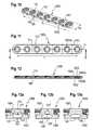
- a plurality of first cavities 120are provided that extend along the whole width from one side to the opposite side of the bone plate 1000.
- the first cavities 120are arranged near the lower surface 1002 and open into the lower surface 100 through slits 130 as shown in Fig. 13a ).
- the first cavities 120have a straight shape in a direction perpendicular to the longitudinal direction and in a cross-sectional view as shown in Fig. 12 an oval-shaped cross-section.
- the second cavities 121may have the same size and the same shape than the first cavities 120 or may have a different size and shape.
- the second cavities 121are smaller than the first cavities 120 thereby rendering the flexibility of the bone plate in view of bending the upper direction smaller than the flexibility in view of bending into the lower direction.
- the first and second cavities 120, 121are arranged at positions between the holes 1003.
- the size, shape, number and position of the cavities 120 and the slits 130determine the flexible characteristics of the bone plate. Hence, by selecting the appropriate design, position and number of the cavities, the bone plate can be rendered flexible according to specific requirements.
- Figs. 13b) and 13cshow further modifications of the design of the bone plate.
- third cavities 122'are provided upon the first cavities 120' in a transverse direction and are connected to the first cavities 120' by slits 131'.
- the size and shape of the third cavities 120'and of the corresponding slits 131may be for example, smaller than that of the first cavities 120' and corresponding slits 130'.
- the width of the first slit 130'is larger than the width of the third slit 132'.
- the bone plate 1000may be manufactured using a conventional manufacturing process. That means, also the cavities and the slits can be manufactured using a conventional manufacturing process, such as electrical discharge machining (EDM). This is possible, because the cavities have a straight configuration. Alternatively, additive manufacturing methods, such as Selective Laser Sintering may be used also to manufacture the bone plate 1000.
- EDMelectrical discharge machining
- the modified design of the cavities as shown in Figs. 7a) to 7c ) and/or the modified design of the slits as shown in Figs. 8 and 9can be used.
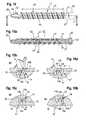
- a fourth embodiment of the implant in the form of a bone screw 1'will be described with reference to Figs. 14 to 17b ). Parts and portions that are identical or similar to the above described embodiments are marked with the same reference numerals and the description thereof is not repeated.
- the bone screw 1'differs from the bone screw 1 according to the first to third embodiments in the design of the cavity.
- the cavity 12'is composed of several sections, that are formed by the inner wall of the cavity 12'.
- the first sectioncomprises the slit 13 that extends in a cross-sectional view as shown in Figs. 15a) and 15b ), substantially perpendicular to the longitudinal axis L and that is open to the surface.
- the wall of the cavity 12' in the section comprising the slit 13forms the two opposing wall portions 13a, 13b as in the first embodiment, the distance of which defines the width ws of the slit 13.
- the slit 13opens to the surface at a position between the crests of the bone thread 11, i.e. in the root of bone thread 12 and extends in a helical shape around the longitudinal axis L.
- the cavity 12'comprises a substantially L-shaped section 14, that has opposing wall portions 14a, 14b forming the bottom of the L-shape that are substantially parallel to the opposing wall portions 13a, 13b of the slit 13 in the cross-sectional view.
- the upper portion of L-shaped cavity portion that is adjacent to the slit 13is connected to the slit 13.
- the slit 13 and the L-shaped section 14 of the cavityresemble a groove and a projection that engages the groove with a gap 14c between the bottom of the groove and the side walls of the groove on the one hand and the projection on the other hand.
- the gap 14callows the projection to move within the groove.
- the cavity 12'comprises a substantially straight section 15 that extends substantially parallel to the longitudinal axis L.
- a width of the substantially straight section 15 in the longitudinal directionmay be smaller than a width ws of the slit 13.
- the straight section 15goes over in an end section 16 that has a substantially oval-shaped cross section with its long sides substantially perpendicular to the longitudinal axis L.
- the course of the sections of the cavityresembles an S-shape, inverted S-shape or a double hook with substantially rectangular, rounded edges.
- the end section 16may have a greater width compared to the width ws of the slit 13 and provided space for compression.
- the orientation of the cavity 12'is from the slit 13 towards the tip 30 of the bone screw.
- a width of the cavity 12' in the longitudinal directionis smaller than a length of the flexible section of the bone screw 1'.
- the opposing wall portions 13a, 13b of the slit 13form first opposing surfaces and provide a first stop at the compression side P when they are abutting against each other when the bone screw is flexed, as described below.
- the opposing wall portions 14a, 14b of the L-shaped section 14form second opposing surfaces that provide a second stop when they are abutting against each other when the bone screw experiences tensile strain on the tension side T.
- the end section 16 of the cavity 12'may extend in the longitudinal direction until a position corresponding to a crest of the bone thread 11.
- the cavity 12'exhibits a plurality of cavity portions in a cross-sectional view, as shown in Fig. 15a ), that are separated from each other in the longitudinal direction by the solid body of the bone screw 1'.
- the cavity 12'In a radial or transverse direction, the cavity 12' is located in an outer half of the radius of the shank 10. More specifically, seen in the radial direction, the cavity 12' located is closer to the outer surface than to the longitudinal axis L.
- Fig. 15b) to 16bshow enlarged views of a portion of the bone screw 1' of Fig. 15a ) wherein the portion includes the cavity 12'.
- Figs. 15b) and 15c )depict the cavity 12' in a condition, in which no transverse force acts onto the bone screw 1.
- Fig. 15b )shows a portion of the cavity 12' that is in Fig. 15a ) on one side of the shank 10 and is marked with X1.
- Fig. 15cshows a portion of the cavity 12' that is arranged with the slit 13 opening to the opposite side of the shank 10 and that is marked in Fig.
- the shank 10has a straight shape.
- the first opposing wall portions 13a, 13bdo not contact each other and their distance corresponds to the distance ws of the slit 13.
- the second opposing wall portions 14a, 14bhave a distance from each other and do not contact each other.
- FIGs. 16a) and 16b )show a condition, in which a transverse force F acts onto the bone screw 1' when load is applied on the tension side T.
- the cavity 12'allows the shank 10 to bend, thereby moving the opposing wall portions 13a, 13b of the slit 13 towards each other.
- the slit 13is closed and a first stop is formed.
- the shank 10is constrained in view of further bending.
- the first stop created by the opposing wall portions 13a, 13b of the slit 13acts as a limit for the compression load applied to the bone screw 1' transverse to the longitudinal direction.
- a second stopis provided by the abutment of the opposing wall portions 14a, 14b on the cavity portion that opens to the tension side T as shown in Fig. 16a ).
- the abutmentmay take place simultaneously with the abutment of the opposing wall portions 13a, 13b, that form the first stop.
- the second stopprevents further bending that would increase the width of the slit 13 on the tension side.
- the forcecan also be transferred via the abutting surfaces 14a, 14b.
- the stiffness of the implantis controlled by the geometric design, such as the volume of the cavity portions, the width of the slit 13 and the distance of the opposing wall portions 14a, 14b.
- the first stop and the second stop provided by the abutting opposing wall portions 13a, 13b and 14a, 14bprovides a self-constraining characteristic to the implant. Therefore, no external or separate part that provides a flexibility constraining effect is required.
- the rod 100'comprises the cavity 12' that has a shape identical or similar to the cavity 12' provided in the bone screw 1' according to the third embodiment.
- the geometry of the cavity 12'may vary along the longitudinal direction of the rod 100' to generate different portions having a different stiffness.
- the pitch of the helixmay be same and may vary along the length of the rod.
- the rodmay also be manufactured through an additive manufacturing method, such as Selective Laser Sintering.
- the shape of the cavity 12' with the first opposing wall portions 13a, 13b and the second opposing wall portions 14a, 14ballows the rod to perform a constrained motion when a transverse load is applied.
- Fig. 19shows a modified embodiment that is modified with regard to the shape of the cavity. Parts and portions that are identical to the parts and portions of the cavity shown in the previous embodiment have the same reference numerals.
- the cavity 12"comprises the end portion 16 and the slit 13 as in the first embodiment. Between the end portion 16 and the slit 13, there is a middle portion 14' that resembles a rectangular groove and projection configuration and a straight portion 15a, 15b at either end thereof that connects the middle portion 14' with the end portion 16 and the slit 13, respectively.
- a first stopis in this case provided by the side wall portions 14a2, 14b2 of the arc-shaped middle portion 14' that are closer to the slit 13 and the second stop is provided by the opposing wall portions 14a1, 14b1 of the middle portion 14' that are closer to the end portion 16.
- the opposing wall portions 13a, 13b of the slit 13can act as a third stop.
- two stiffness zonesmay be provided at the compression side P. An initial contact is established by the first stop of the abutting surfaces 14a2, 14b2 and upon further bending a second contact is provided by the third stop.
- the cavity 12' according to the fourth and the fifth embodiment or the modified cavity 12"may also be provided in a bone plate (not shown).
- the cavity 12' or 12"is arranged in the bone plate in a transverse direction and extends from one side to the other side similar to the cavity 120 in the bone plate shown in Figs. 10 to 12 .
- at least one cavity 12' or 12"is provided near the lower side 1002 of the bone plate and the other cavity 12' or 12" is provided near the upper side 1001 of the bone plate.
- Such upper and lower cavitiesmay be provided in a first arrangement at the same position in longitudinal direction of the bone plate or, in a second arrangement, may be offset from each other in the longitudinal direction. The second arrangement bas an increased strength compared to the first arrangement.
- FIG. 20 to 22An implant according to a sixth embodiment in the form of a bone screw is shown in Figs. 20 to 22 .
- longitudinal slits 40may be provided that extend from the outermost portion of the tip 30 into the shank 10.
- the slits 40are equidistantly arranged in a circumferential direction, for example three or more slits 40 may be provided.
- the depth of the slits 40 in the radial directioncorresponds substantially to a depth to which the end section 16 of the cavity 12' extends.
- the slits 40have substantially rectangular cross-sections with a widened end portion 41, for example with a hollow cylinder segment-shaped inner wall and with an inner diameter that is greater than the width of the outer portion of the slit 40, as can be seen in Fig. 22 .
- a width of the outer portion of the slit 40may be smaller than a width of the cutting edges 32 as can be seen, for example, in Fig. 21 .
- the slits 40may extend up to the center of the shank 10 in the longitudinal direction.
- the dimensions and the number of the slitsare not limited to the embodiment shown.
- the slitscould be shorter or longer in the longitudinal direction, could have a greater or smaller depth and a greater or smaller width depending on the desired flexibility.
- the slits 40can have a small width, similar to that of the helical slit 13 and the widened portion 41 can act as the cavity of the previous embodiments. With this design the bending and torsional stiffness of the implant can be influenced.
- the implantis in the form of a bone screw 1'" comprising a head 20, a tip 3 0 and a shank portion 10 with a bone thread 11.
- the bone screwdoes not have the helical cavity and the helical slit as the previous embodiments.
- the bone screw 1"'comprises longitudinal slits 400 that extend from the outermost portion of the tip 30 into the shank 10.
- the slits 400are equidistantly arranged in a circumferential direction, in the embodiment shown, three slits 400 are provided.
- the slits 400have substantially rectangular cross-sections with a widened end portion 401, for example with a hollow cylinder segment-shaped inner wall and with an inner diameter w in the transverse direction that is greater than the width ws of the outer portion of the slit 400 in the transverse direction, as can be seen in Fig. 25 .
- the widened portion 401forms a cavity.
- the end portions 401 of the slits 400may be drilled from the side of the tip into the shank in a longitudinal direction. Thereafter, the outer portion of the slits that is open to the outer surface may be cut by, for example, wire cutting.
- the whole implantcan be made by additive manufacturing, for example by Laser Sintering.
- the implant with the cavitiesis formed by additive manufacturing and the slits are cut by wire cutting, for example.
- the slitscan also be provided at a portion of the shank that is position apart from the tip, for example the slits can start at a distance of the tip end at a distance from the head.
- the position of the slits in the longitudinal directionmay vary from one slit to the other slit.
- the slits 400 with cavities 401lead to a self constrained torsional flexibility.
- the slits 400will be closed at a position along the shank where the torsional load becomes too large. This prevents further torsion of the implant.
- the implanthas due to its structure at least two stiffness zones in a load versus twisting curve.
- a bone screw of a core diameter of X 1may have initially the lower torsional stiffness of a bone screw with a core diameter of X 2 ⁇ X 1 , for example 3.5mm, when the slit is not yet closed and may have subsequently upon further twisting the greater torsional stiffness of a bone screw with a core diameter of X 1 when the slit is closed.
- the implant according to the seventh embodimentcan also be a rod or any other implant that may experience torsional loads.
- the implantsmay be flexible along a length that corresponds only to a portion of the implant, wherein in this case a flexible section is defined by the presence of the cavities and the slits.
- the implantcan also be realized through any bone anchor, with or without a threaded shank, for example a bone nail.
- the slitsneed not to have exactly parallel opposing surfaces. In suffices that an abutment takes place when the slit narrows, that prevents further flexion.
- the interlocking structure of the slit 13', 13" as shown in Figs. 8 and 9may be provided also for the fourth and fifth embodiment.
- Features of one embodimentmay be combined with features of one or several of the other embodiments.
- the at least one cavity and the at least one slitmay be realized by several annular cavities with annular slits extending around the central axis.
- the cavities with slitscan be axial cavities with axial slits for any of the implants.
- the cavities with slitscan also have interruptions along their length.
- the shape of the cavity, in particular the depth of the cavitycan vary along a length of the implant, for example, there can be a deep cavity on a first portion of the screw length, such as adjacent to the tip, and a shallow cavity along a second portion of the screw length.
- the inventionis not limited to implants having a straight shape.
- the bone platemay have a curvature along its length and/or width and may be formed with an irregular outer contour.
- a humerus platemay have such a curvature in at least a portion of its length.
- curved rods, straight nails and curved nailsmay be contemplated. If the implant has a curvature along at least a portion of its length, the longitudinal axis is defined as a curved central line extending through the implant along its length.
Landscapes
- Health & Medical Sciences (AREA)
- Orthopedic Medicine & Surgery (AREA)
- Surgery (AREA)
- Life Sciences & Earth Sciences (AREA)
- Neurology (AREA)
- Engineering & Computer Science (AREA)
- Molecular Biology (AREA)
- Biomedical Technology (AREA)
- Heart & Thoracic Surgery (AREA)
- Medical Informatics (AREA)
- Nuclear Medicine, Radiotherapy & Molecular Imaging (AREA)
- Animal Behavior & Ethology (AREA)
- General Health & Medical Sciences (AREA)
- Public Health (AREA)
- Veterinary Medicine (AREA)
- Manufacturing & Machinery (AREA)
- Mechanical Engineering (AREA)
- Chemical & Material Sciences (AREA)
- Materials Engineering (AREA)
- Physics & Mathematics (AREA)
- Optics & Photonics (AREA)
- Prostheses (AREA)
- Surgical Instruments (AREA)
Abstract
Description
- The invention relates to a flexible implant for the stabilization of bones or vertebrae, wherein the implant is formed as a solid body that has at least one cavity located near the surface wherein the cavity is connected to the surface through at least one slit and wherein a width of the slit is smaller than a width of the cavity. The slit is configured to narrow when the implant is flexed and the closing of the slit during flexion limits the extent of flexion of the implant. The implant may be realized, for example, as a bone screw, a stabilization rod or a bone plate.
- Dynamic stabilization devices are known, in which the bone parts or vertebrae to be stabilized are able to carry out a controlled limited motion relative to each other. For example, a rod-shaped implant for the connection of bone anchoring elements that comprises at least one rigid section that is configured to be placed in a receiver member of a bone anchoring element and a flexible section that is adjacent to the rigid section and wherein the flexible section and the rigid section are formed as a continuous one-piece element is known from
US 7,621,912 B2 . - An elastic or flexible element for use in a stabilization device for bones or vertebrae in the form of a helical spring is known from
US 2005/0154390 A1 . The flexible element can be part of the shaft of a flexible bone screw or of a stabilization rod or a plate. - Such known flexible implants comprise a longitudinal bore and a helical slot-shaped opening in the wall. The flexibility is determined by the geometry of the hollow bore and the helical slot-shaped opening. To limit the flexibility or strengthen the implant, a core may be provided in the hollow bore. The flexible characteristics of the known devices can be precisely designed by the geometry of the helical slot-shaped opening and the dimensions of the hollow bore and optionally the core inserted therein. However, such implants sometimes do not have a limitation of the flexibility or a limitation of the flexibility to a certain degree requires a more complex design in terms of the number of parts or the materials used. Therefore, there remains a need for a further improved flexible implant.
- It is the object of the invention to provide a flexible implant that has an improved strength and is easy to manufacture. The object is solved by the implant according to claim 1. Further developments are given in the dependent claims.
- The implant is an elongate solid body that obtains flexibility by a plurality of cavities or cavity portions near the outer surface that are connected to the surface through a slit. Such a monolithic structure leads to lower production costs, since no assembly is required. The stiffness can be designed and controlled by the geometric design as opposed to relying on exotic and costly materials. The implant can be manufactured using electrical discharge machining (EDM) in particular wire cutting, and/or an additive manufacturing technology, such as, for example, Selective Laser Sintering using a metallic or plastic powder material.
- The monolithic structure provided by the solid body provides a degree of flexibility and dynamic motion while simultaneously exhibiting sufficient strength. In particular, it is possible to provide a thin elongate implant, that has a smaller core diameter compared to elongate implants with a hollow interior, or, if it has substantially the same diameter as an implant with hollow interior, shows less bending. The implant may be preferably a bone screw, a stabilization rod or a bone plate. However, it can be any other implant that is required to have flexible characteristics.
- According to another aspect, the implant has substantially the same strength and/or volume or diameter as a conventional non-flexible implant, but exhibits a micro-motion due to its structure with inherent flexibility.
- The motion of the implant can be constrained by a built-in geometric design that allows movement with an elastic loading curve until a limit is reached. This limit may be created by surfaces provided at the implant that contact each other so that further flexion is prevented. Because the flexibility of the implant is self-constrained, an external geometry to provide this limit is not required.
- In a further development, a tension side of the implant is defined as the side where load is applied to the implant in a transverse direction and a compression side of the implant is defined by the side of the implant that is compressed when the load is applied in the transverse direction. The at least one cavity includes a structure that forms a first stop to limit the flexion of the implant on the compression side and/or a second stop to limit the tensile strain and flexion on the tension side. Via the second stop, forces can be transmitted also via the tension side.
- It may be possible to design two or more stiffness zones depending on the desired application. In addition, the size and shape of the cavities may be designed such that load peaks acting onto the implant during flexion that could cause cracks in the implant body are prevented.
- In a further embodiment, a longitudinal implant has a self constrained torsional flexibility. Consequently, it is also possible to have an implant with two or more stiffness zones with regard to torsional loads.
- Further features and advantages will become apparent from the description of embodiments by means of the accompanying drawings. In the drawings:
- Fig. 1
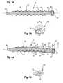
- shows a perspective view of an implant according to a first embodiment which is in the form of a bone screw.
- Fig. 2
- shows a side view of the bone screw shown in
Fig. 1 . - Fig. 3a)
- shows a cross-sectional view of the bone screw shown in
Fig. 2 along line A-A inFig. 2 . - Fig. 3b)
- shows an enlarged view of a detail of
Fig. 3a ). - Fig. 4a)
- shows a cross-sectional view of the bone screw shown in
Fig. 2 along line A-A inFig. 2 wherein a force acts onto the bone screw that deflects the bone screw in a transverse direction. - Fig. 4b)
- shows an enlarged view of a detail of
Fig. 4a ). - Fig. 5
- shows a side view of an implant according to a second embodiment in the form of a stabilization rod.
- Fig. 6a)
- shows a cross-sectional view of the stabilization rod shown in
Fig. 5 along line B-B inFig. 5 . - Fig. 6b)
- shows an enlarged view of a detail of
Fig. 6a ). - Figs.7a) to 7c)
- show an enlarged cross-sectional view of modifications of the shape of the cavity shown in
Fig. 6a ). - Fig. 8
- shows an enlarged cross-sectional view of a modification of the design of the slit shown in
Fig. 6a ). - Fig. 9
- shows an enlarged cross-sectional view of a further modification of the design of the slit shown in
Fig. 6a ). - Fig. 10
- shows a third embodiment of the implant in the form of a bone plate.
- Fig. 11
- shows a top-view of the bone plate of
Fig. 10 . - Fig. 12
- shows a cross-sectional view of the bone plate of
Fig. 11 along line C-C inFig. 11 . - Figs. 13a) to 13c)
- show an enlarged view of various modifications of the cavities in the bone plate.
- Fig. 14
- shows a side view of an implant according to a forth embodiment which is in the form of a bone screw.
- Fig. 15a)
- shows a cross-sectional view of the bone screw shown in
Fig. 14 along line D-D inFig. 14 . - Fig. 15b)
- shows an enlarged view of a detail comprising a portion of the cavity in
Fig. 15a ) at the tension side. - Fig.15c)
- shows an enlarged view of another portion of the cavity shown in
Fig. 15a ) at the compression side. - Fig. 16a)
- shows the cavity shown in
Fig. 15b ) when a transverse force acts onto the bone screw. - Fig. 16b)
- shows the cavity shown in
Fig. 16a ) when the transverse force acts onto the bone screw. - Fig. 17
- shows a side view of an implant according to a fifth embodiment in the form of a stabilization rod.
- Fig. 18
- shows a cross-sectional view of the stabilization rod shown in
Fig. 18 along line E-E inFig. 17 . - Fig. 19
- shows an enlarged cross-sectional view of a modification of the shape of the cavity shown in
Figs. 14 to 18 . - Fig. 20
- shows a side view of an implant in the form of a bone screw according to a sixth embodiment
- Fig. 21
- shows a cross-sectional view of the bone screw shown in
Fig. 20 along line F-F inFig. 20 . - Fig. 22
- shows an enlarged cross sectional view of a detail of
Fig. 21 . - Fig. 23
- shows a side view of an implant in the form of a bone screw according to a seventh embodiment
- Fig. 24
- shows a cross-sectional view of the bone screw shown in
Fig. 23 along line G-G inFig. 23 . - Fig. 25
- shows an enlarged cross-sectional view of the bone screw shown in
Fig. 24 along line I-I inFig. 23 . - A first embodiment of the implant will be described with reference to
Figs. 1 to 4b ). The implant is a bone screw 1 that comprises ashank 10 with abone thread 11 in at least a portion thereof, ahead 20 at one end, atip 30 at the opposite end of theshank 10 and a longitudinal axis L that forms the screw axis. Referring in particular toFigs. 3a) and 3b ), the portion of theshank 10 that is provided with thebone thread 11, i.e. the bone thread portion, has an outer surface and a length 1. The bone screw is formed as a monolithic, solid body. In particular, it has a solid, non-cannulated interior. At a distance from the outer surface acavity 12 is formed that extends in a helical path around the longitudinal axis L of the bone screw over the length 1 of the bone thread portion. The spinning direction of thehelical cavity 12 is the same as the direction of the thread. Thecavity 12 has an oval-shaped cross-section in a direction perpendicular to the longitudinal axis L. A width w of thecavity 12 in the direction of the longitudinal axis L is smaller than the length 1 of the bone thread portion. - The width w of the cavities in the longitudinal direction is furthermore such that it is smaller than a thread pitch, i.e. the distance between the crests of the bone thread in the longitudinal direction. As can be seen in particular in
Fig. 3a ), thecavity 12 is located at a position that corresponds to the root of thebone thread 11. Furthermore, thecavity 12 is open to the outer surface of the shank by means of aslit 13 that extends in a helical manner around the longitudinal axis L as can be seen in particular inFigs. 1 and 2 . Theslit 13 comprises opposingsurfaces surfaces - The
slit 13 opens into thecavity 12 at a position that corresponds substantially to the center of thecavity 12 in a longitudinal direction. By this design, the helically-shapedcavity 12 exhibits a plurality of cavity portions in a cross-sectional view, as shown inFig. 3a ), that are separated from each other in the longitudinal direction by the solid body of the bone screw 1. The width ws of the slit is smaller than the width w of thecavity 12 in a longitudinal direction. More specifically, the slit has such a size that the shank portion between the cavity and the outer surface, that is on both sides of the slit, is thinned. Therefore, the screw is flexible in the region of the cavity. The length of the slit in the transverse direction is such that thecavity 12 is located in an outer half of the radius of theshank 10. More specifically, seen in a radial direction, thecavity 12 is closer to the outer surface than to the longitudinal axis L. - The
tip 30 of the bone screw may be a self-cutting tip. The self-cuttingtip 30 comprises bone-threadfree sections 31 that extend in a slightly twisted-manner from the outermost portion of thetip 30 into the shank, thereby creating cutting edges 32. Furthermore between thehead 20 and the bone thread portion of theshank 10, there may be aneck portion 21. Thehead 20 shown in the embodiment is a spherically-segment shapedhead 20 and comprises anengagement portion 22 for a tool. - The bone screw 1 is preferably made from a biocompatible metal or a biocompatible metal or metal alloy such as stainless steel, titanium or a nickel-titanium alloy. In particular, alloys having superelasticity such as Nitinol or superelastic ß-titanuim alloys are suitable. It can also be made from a biocompatible plastic material, such as, for example from PEEK (polyetheretherketone).
- To obtain the monolithic, solid structure, the bone screw is preferably manufactured using an additive manufacturing method, such as Selective Laser Sintering (SLS), Selective Laser Melting or electron beam melting. With such a method, it is possible to fabricate the
internal cavities 12 into the solid body and theslit 13 during the layer-wise build-up of the implant based on computer data defining the shape and size of the implant. When using Selective Laser Sintering or Selective Laser Melting, laser sinterable metals or metal alloys or laser sinterable plastic materials are to be used, for example, laser sinterable titanium powder or laser sinterable stainless steel powder or laser sinterable PEEK powder. - In a modified method of manufacturing, the solid body with the internal cavities is made by an additive manufacturing method, in particular by SLS, while the slits remain still closed. Thereafter, the slits are cut using a conventional technique such as wire cutting.
- In use, when a force F that is directed transverse to the longitudinal axis L acts onto the bone screw 1, the bone screw 1 is flexible in a direction transverse to the longitudinal direction, as can be seen in
Fig. 4a ). The side where the load is applied in the transverse direction is defined as a tension side T of the implant. Thecavity 12 and slit 13 that is connected to thecavity 12 allows the bone screw to bend, thereby moving the opposingsurfaces slit 13 towards each other. The side where the implant is compressed is defined as a compression side P of the implant. When the opposingsurfaces slit 13 is closed, the bone screw 1 is constrained in view of further bending. Thus, the stop created by the opposingsurfaces cavity 12 and the length and width of theslit 13. The stop provided by the abuttingsurfaces slit 13 provides a self-constraining characteristic to the bone screw. Therefore, no external or separate part that provides a flexibility constraining effect is required. Due to the helical structure of thecavity 12, bending of the bone screw is constrained in view of all directions perpendicular to the longitudinal axis L. - Because the bone screw 1 is manufactured from a solid body and does not comprise a central longitudinal bore, the strength of the bone screw may be higher than that of known flexible bone screws that comprise a spring element for providing the flexibility. This reduces a risk of failure due to cracking. Because the strength is increased, it may be possible to manufacture the bone screw 1 with a smaller core diameter compared to flexible implants with a hollow interior. Due to its structure, the implant has at least two stiffness zones in a load versus displacement curve. An initial lower stiffness due to the possible micro-motion, that resembles the stiffness of an implant with a smaller diameter and a subsequent higher stiffness that resembles the stiffness of an implant with a greater diameter. For example, a bone screw of a core diameter of X1, for example 7mm, may have initially the lower stiffness of a bone screw with a core diameter of X2 < X1, for example 3.5mm, when the gaps are not yet closed and may have subsequently upon further bending the greater stiffness of a bone screw with a core diameter of X1 when the slit is closed.
- The bone screw may be used, for example, as a pedicle screw. In this case, it can be connected to a receiving part to form a polyaxial or a monoplanar bone anchor. For the receiving part, all kinds of receiving parts can be used that allow to pivotably hold the head of the bone screw and connect the bone screw to a spinal stabilization rod. When the vertebrae move, transverse forces may act onto the pedicle screw. Due to its flexibility, the pedicle screw can bend and thus prevents fracture of weak bone material.
- Further modifications of the embodiments described may be contemplated. For example, the bone screw is not limited to the embodiment shown, it may have a non self-cutting tip, it may have a different head, such as a lens-shaped head or a disc-shaped head or any other head. It may be even be provided without a head. The bone screw may also be used together with a bone plate.
- A second embodiment of the implant will be described with reference to
Figs. 5 and 6 . Parts or portions that are identical or similar to the first embodiment carry the same reference numerals. The implant in this case is a stabilization rod, for example, for the stabilization of the spinal column. Therod 100 is made as a monolithic, cylindrical solid body having a cylinder or longitudinal axis L, a surface and a length l1. As in the first embodiment, acavity 12 is extending in a helical fashion around the longitudinal axis L at a distance from the surface of therod 100. Thecavity 12 has, as in the first embodiment, an oval-shaped cross-section in a plane containing the longitudinal axis L as can be seen inFig. 6 a) and 6b ). Thecavity 12 opens to the surface via aslit 13, as in the first embodiment, the width ws of the slit being smaller than the width w of thecavity 12 in the longitudinal direction. In particular the width ws is such that seen in the cross-sectional view ofFig. 6 a) a plurality of cavity portions are arranged near the surface and extend in longitudinal direction, which are separated by solid portions of the rod. Thecavity 12 and theslit 13 may extend along the full length of the rod or along a portion of the rod. The geometry of thecavity 12 and of theslit 13 may vary along the longitudinal direction of the rod to generate different portions with different stiffness. The pitch of the helix may be the same or may vary along the length of the rod. - The rod may also be manufactured through an additive manufacturing method, such as Selective Laser Sintering.
- The rod may be used to connect two bone anchoring devices, for example two pedicle screws screwed into the pedicles of adjacent vertebrae. Due to the flexible characteristics of the rod based on the helically-shaped cavity with the helically-shaped slit, the
rod 100 permits a controlled motion of the adjacent vertebrae. The motion is limited by the self constrained flexibility of the rod. - Referring to
Figs. 7b) to 7c ), various modifications of thecavity 12 are shown. As shown inFig. 7a ) the cavity 12' may have a circular cross-section. A reduced volume of the cavity may lead to a higher torsional stiffness. As shown inFig. 12b ), the cross-section of thecavity 12" may be an elongate oval shape with straight long sides, which resembles the cross-section of a capsule. The width w of thecavity 12" with this design is enlarged, resulting in an enhanced bending flexibility. As shown inFig. 7c ), the cross-section may be also have an inverted drop-shape wherein the drop-shape has flattened end portion. The various modifications of the shape of the cavity can be used for therod 100 as well as for the bone screw 1. For a given geometry and size of an implant, it is possible to use various modifications of the shape and volume of the cavity and also the slits in order to design an implant with a particular behaviour, for example, with a specific torsional and bending stiffness. - Referring to
Figs. 8 and 9 , modifications of the design of the slit are shown.Fig. 8 shows a first example of a modification of the slit with an interlocking design. The slit 13' comprises opposingside walls 13a', 13b', that exhibit a V-shape in a cross-sectional view so that theside wall 13a forms a projection and theside wall 13b forms a groove into which the projection fits and interlocks therewith when a force acts onto the implant such that the distance between the opposingsurfaces 13a', 13b' is decreased. Fig. 9 shows a further modification of the design of the slit with an interlocking feature. Theslit 13" comprises opposingside walls 13a", 13b", that have a rectangular cross-section when seen in a cross-sectional view. Hence, theside wall 13a" forms a projection and theside wall 13b" forms a groove and the projection fits into the groove. The examples shown inFigs. 8 and 9 having the interlocking design provide for a more precise adjustment of the flexibility constraining stop. In addition, the interlocking design is a safety means, that prevents the two sides of the slit to slide along each other if the bending load is increased. It can be used with the implant in the form of a bone screw 1 according to the first embodiment or with the implant in the form of astabilization rod 100 according to the second embodiment.- A third embodiment of the implant will be described with reference to
Figs. 10 to 13c ). The implant is abone plate 1000 that comprises anupper surface 1001 and an oppositelower surface 1002 that faces the bone surface when the bone plate is used. Thebone plate 1000 has a length l2 along which it is substantially straight and a width w2 and is typically of a rectangular shape with rounded ends with a longitudinal axis L. However, many different designs of bone plates may be contemplated as well. Thebone plate 1000 further comprises at least two, usually a plurality ofholes 1003 extending from theupper surface 1001 to thelower surface 1002. Theholes 1003 may be provided with aseat 1003a for a bone screw and aninternal thread 1003b for a locking cap (both not shown). - In the embodiment shown, a plurality of
first cavities 120 are provided that extend along the whole width from one side to the opposite side of thebone plate 1000. Thefirst cavities 120 are arranged near thelower surface 1002 and open into thelower surface 100 throughslits 130 as shown inFig. 13a ). Thefirst cavities 120 have a straight shape in a direction perpendicular to the longitudinal direction and in a cross-sectional view as shown inFig. 12 an oval-shaped cross-section. Near theupper surface 1002, there aresecond cavities 121 that are arranged opposite to thefirst cavities 120 and open into theupper surface 1002 via aslit 131 as shown inFig. 13a ). Thesecond cavities 121 may have the same size and the same shape than thefirst cavities 120 or may have a different size and shape. In the example shown, thesecond cavities 121 are smaller than thefirst cavities 120 thereby rendering the flexibility of the bone plate in view of bending the upper direction smaller than the flexibility in view of bending into the lower direction. The first andsecond cavities holes 1003. - As in the previous embodiments, the size, shape, number and position of the
cavities 120 and theslits 130 determine the flexible characteristics of the bone plate. Hence, by selecting the appropriate design, position and number of the cavities, the bone plate can be rendered flexible according to specific requirements. Figs. 13b) and 13c ) show further modifications of the design of the bone plate. InFig. 13b ), third cavities 122' are provided upon the first cavities 120' in a transverse direction and are connected to the first cavities 120' by slits 131'. The size and shape of the third cavities 120'and of the correspondingslits 131 may be for example, smaller than that of the first cavities 120' and corresponding slits 130'. In the embodiment, the width of the first slit 130' is larger than the width of the third slit 132'.- With the design according to
Fig. 13b ) two stiffness zones are created by the first cavities 120' and by the second cavities 122', respectively. When a transverse force acts onto the bone plate, an initial contact is made by the opposing surfaces of the third slit 132' and upon further bending, a secondary contact is established between the opposing surfaces of the first slit 130'. - Providing
cavities 120 only on one side, for example near to thelower surface 1002 as shown inFig. 13c ), allows a constrained flexibility in one direction only. - The
bone plate 1000 may be manufactured using a conventional manufacturing process. That means, also the cavities and the slits can be manufactured using a conventional manufacturing process, such as electrical discharge machining (EDM). This is possible, because the cavities have a straight configuration. Alternatively, additive manufacturing methods, such as Selective Laser Sintering may be used also to manufacture thebone plate 1000. - Also for the bone plate, the modified design of the cavities as shown in
Figs. 7a) to 7c ) and/or the modified design of the slits as shown inFigs. 8 and 9 can be used. - A fourth embodiment of the implant in the form of a bone screw 1' will be described with reference to
Figs. 14 to 17b ). Parts and portions that are identical or similar to the above described embodiments are marked with the same reference numerals and the description thereof is not repeated. The bone screw 1' differs from the bone screw 1 according to the first to third embodiments in the design of the cavity. The cavity 12' is composed of several sections, that are formed by the inner wall of the cavity 12'. The first section comprises theslit 13 that extends in a cross-sectional view as shown inFigs. 15a) and 15b ), substantially perpendicular to the longitudinal axis L and that is open to the surface. The wall of the cavity 12' in the section comprising theslit 13 forms the two opposingwall portions slit 13. As can be seen in particular inFigs. 14 and 15a ), theslit 13 opens to the surface at a position between the crests of thebone thread 11, i.e. in the root ofbone thread 12 and extends in a helical shape around the longitudinal axis L. - Following the
slit 13, the cavity 12' comprises a substantially L-shapedsection 14, that has opposingwall portions wall portions slit 13 in the cross-sectional view. The upper portion of L-shaped cavity portion that is adjacent to theslit 13 is connected to theslit 13. Seen as a whole, theslit 13 and the L-shapedsection 14 of the cavity resemble a groove and a projection that engages the groove with agap 14c between the bottom of the groove and the side walls of the groove on the one hand and the projection on the other hand. Thegap 14c allows the projection to move within the groove. Following the L-shapedsection 14, the cavity 12' comprises a substantiallystraight section 15 that extends substantially parallel to the longitudinal axis L. A width of the substantiallystraight section 15 in the longitudinal direction may be smaller than a width ws of theslit 13. Finally, thestraight section 15 goes over in anend section 16 that has a substantially oval-shaped cross section with its long sides substantially perpendicular to the longitudinal axis L. Seen in the cross-sectional view as shown inFigs. 15b) and 15c ), the course of the sections of the cavity resembles an S-shape, inverted S-shape or a double hook with substantially rectangular, rounded edges. Theend section 16 may have a greater width compared to the width ws of theslit 13 and provided space for compression. The orientation of the cavity 12' is from theslit 13 towards thetip 30 of the bone screw. - Also in this embodiment is a width of the cavity 12' in the longitudinal direction is smaller than a length of the flexible section of the bone screw 1'.
- The opposing
wall portions slit 13 form first opposing surfaces and provide a first stop at the compression side P when they are abutting against each other when the bone screw is flexed, as described below. The opposingwall portions section 14 form second opposing surfaces that provide a second stop when they are abutting against each other when the bone screw experiences tensile strain on the tension side T. In the longitudinal direction, theend section 16 of the cavity 12' may extend in the longitudinal direction until a position corresponding to a crest of thebone thread 11. - By the helical design of the cavity 12' as described above, the cavity 12' exhibits a plurality of cavity portions in a cross-sectional view, as shown in
Fig. 15a ), that are separated from each other in the longitudinal direction by the solid body of the bone screw 1'. In a radial or transverse direction, the cavity 12' is located in an outer half of the radius of theshank 10. More specifically, seen in the radial direction, the cavity 12' located is closer to the outer surface than to the longitudinal axis L. - The function of the bone screw 1' in use will be described with reference to
Figs. 15b) to 16b). Fig. 15b) to 16b ) show enlarged views of a portion of the bone screw 1' ofFig. 15a ) wherein the portion includes the cavity 12'.Figs. 15b) and 15c ) depict the cavity 12' in a condition, in which no transverse force acts onto the bone screw 1. Specifically,Fig. 15b ) shows a portion of the cavity 12' that is inFig. 15a ) on one side of theshank 10 and is marked with X1.Fig. 15c ) shows a portion of the cavity 12' that is arranged with theslit 13 opening to the opposite side of theshank 10 and that is marked inFig. 15a ) with X2. When no transverse force acts onto theshank 10, theshank 10 has a straight shape. The first opposingwall portions slit 13. The second opposingwall portions - When a force F that is directed transverse to the longitudinal axis L acts onto the bone screw 1', the bone screw 1' is flexible in a direction transverse to the longitudinal direction.
Figs. 16a) and 16b ) show a condition, in which a transverse force F acts onto the bone screw 1' when load is applied on the tension side T. The cavity 12' allows theshank 10 to bend, thereby moving the opposingwall portions slit 13 towards each other. When the opposingwall portions slit 13 is closed and a first stop is formed. Theshank 10 is constrained in view of further bending. Thus, the first stop created by the opposingwall portions slit 13 acts as a limit for the compression load applied to the bone screw 1' transverse to the longitudinal direction. - A second stop is provided by the abutment of the opposing
wall portions Fig. 16a ). The abutment may take place simultaneously with the abutment of the opposingwall portions slit 13 on the tension side. In addition, by means of the second stop the force can also be transferred via the abuttingsurfaces - The stiffness of the implant is controlled by the geometric design, such as the volume of the cavity portions, the width of the
slit 13 and the distance of the opposingwall portions wall portions - A fifth embodiment of the implant in the form of a stabilization rod will be described with reference to
Figs. 17 and 18 . Parts or portions that are identical or similar to the previous embodiment are indicated with the same reference numerals. The rod 100' comprises the cavity 12' that has a shape identical or similar to the cavity 12' provided in the bone screw 1' according to the third embodiment. The geometry of the cavity 12' may vary along the longitudinal direction of the rod 100' to generate different portions having a different stiffness. The pitch of the helix may be same and may vary along the length of the rod. - The rod may also be manufactured through an additive manufacturing method, such as Selective Laser Sintering.
- In use, the shape of the cavity 12' with the first opposing
wall portions wall portions Fig. 19 shows a modified embodiment that is modified with regard to the shape of the cavity. Parts and portions that are identical to the parts and portions of the cavity shown in the previous embodiment have the same reference numerals. Thecavity 12" comprises theend portion 16 and theslit 13 as in the first embodiment. Between theend portion 16 and theslit 13, there is a middle portion 14' that resembles a rectangular groove and projection configuration and astraight portion end portion 16 and theslit 13, respectively. A first stop is in this case provided by the side wall portions 14a2, 14b2 of the arc-shaped middle portion 14' that are closer to theslit 13 and the second stop is provided by the opposing wall portions 14a1, 14b1 of the middle portion 14' that are closer to theend portion 16. The opposingwall portions slit 13 can act as a third stop. In such a case, two stiffness zones may be provided at the compression side P. An initial contact is established by the first stop of the abutting surfaces 14a2, 14b2 and upon further bending a second contact is provided by the third stop.- The cavity 12' according to the fourth and the fifth embodiment or the modified
cavity 12" may also be provided in a bone plate (not shown). Thecavity 12' or 12" is arranged in the bone plate in a transverse direction and extends from one side to the other side similar to thecavity 120 in the bone plate shown inFigs. 10 to 12 . In order to limit the flexion also on the tension side, at least onecavity 12' or 12" is provided near thelower side 1002 of the bone plate and theother cavity 12' or 12" is provided near theupper side 1001 of the bone plate. Such upper and lower cavities may be provided in a first arrangement at the same position in longitudinal direction of the bone plate or, in a second arrangement, may be offset from each other in the longitudinal direction. The second arrangement bas an increased strength compared to the first arrangement. - An implant according to a sixth embodiment in the form of a bone screw is shown in
Figs. 20 to 22 . To enhance the flexibility of the bone screw further,longitudinal slits 40 may be provided that extend from the outermost portion of thetip 30 into theshank 10. Theslits 40 are equidistantly arranged in a circumferential direction, for example three ormore slits 40 may be provided. The depth of theslits 40 in the radial direction corresponds substantially to a depth to which theend section 16 of the cavity 12' extends. Theslits 40 have substantially rectangular cross-sections with awidened end portion 41, for example with a hollow cylinder segment-shaped inner wall and with an inner diameter that is greater than the width of the outer portion of theslit 40, as can be seen inFig. 22 ., A width of the outer portion of theslit 40 may be smaller than a width of the cutting edges 32 as can be seen, for example, inFig. 21 . Furthermore, theslits 40 may extend up to the center of theshank 10 in the longitudinal direction. The dimensions and the number of the slits are not limited to the embodiment shown. The slits could be shorter or longer in the longitudinal direction, could have a greater or smaller depth and a greater or smaller width depending on the desired flexibility. In particular, theslits 40 can have a small width, similar to that of thehelical slit 13 and the widenedportion 41 can act as the cavity of the previous embodiments. With this design the bending and torsional stiffness of the implant can be influenced. - A seventh embodiment of an implant will be described with reference to
Figs. 23 to 25 . The implant is in the form of a bone screw 1'" comprising ahead 20, a tip 3 0 and ashank portion 10 with abone thread 11. The bone screw does not have the helical cavity and the helical slit as the previous embodiments. Instead of these, the bone screw 1"' compriseslongitudinal slits 400 that extend from the outermost portion of thetip 30 into theshank 10. Theslits 400 are equidistantly arranged in a circumferential direction, in the embodiment shown, threeslits 400 are provided. Theslits 400 have substantially rectangular cross-sections with awidened end portion 401, for example with a hollow cylinder segment-shaped inner wall and with an inner diameter w in the transverse direction that is greater than the width ws of the outer portion of theslit 400 in the transverse direction, as can be seen inFig. 25 . The widenedportion 401 forms a cavity. - The
end portions 401 of theslits 400 may be drilled from the side of the tip into the shank in a longitudinal direction. Thereafter, the outer portion of the slits that is open to the outer surface may be cut by, for example, wire cutting. Alternatively, the whole implant can be made by additive manufacturing, for example by Laser Sintering. In a third alternative, the implant with the cavities is formed by additive manufacturing and the slits are cut by wire cutting, for example. - The slits can also be provided at a portion of the shank that is position apart from the tip, for example the slits can start at a distance of the tip end at a distance from the head. The position of the slits in the longitudinal direction may vary from one slit to the other slit.
- In use, the
slits 400 withcavities 401 lead to a self constrained torsional flexibility. When a torsional load acts on the implant, theslits 400 will be closed at a position along the shank where the torsional load becomes too large. This prevents further torsion of the implant. - As in the previous embodiments, the implant has due to its structure at least two stiffness zones in a load versus twisting curve. An initial lower stiffness due to the possible micro-motion, that resembles the torsional stiffness of an implant with a smaller diameter and a subsequent higher torsional stiffness that resembles the torsional stiffness of an implant with a greater diameter. For example, a bone screw of a core diameter of X1, for example 7mm, may have initially the lower torsional stiffness of a bone screw with a core diameter of X2 < X1, for example 3.5mm, when the slit is not yet closed and may have subsequently upon further twisting the greater torsional stiffness of a bone screw with a core diameter of X1 when the slit is closed.
- The implant according to the seventh embodiment can also be a rod or any other implant that may experience torsional loads.
- Various other modifications of the embodiments can be contemplated. For example, the implants may be flexible along a length that corresponds only to a portion of the implant, wherein in this case a flexible section is defined by the presence of the cavities and the slits. The implant can also be realized through any bone anchor, with or without a threaded shank, for example a bone nail.
- The slits need not to have exactly parallel opposing surfaces. In suffices that an abutment takes place when the slit narrows, that prevents further flexion.
- The interlocking structure of the
slit 13', 13" as shown inFigs. 8 and 9 may be provided also for the fourth and fifth embodiment. Features of one embodiment may be combined with features of one or several of the other embodiments. - Instead of the helix-shaped cavities and slits for the bone anchor and the rod, the at least one cavity and the at least one slit may be realized by several annular cavities with annular slits extending around the central axis. Also, the cavities with slits can be axial cavities with axial slits for any of the implants. The cavities with slits can also have interruptions along their length. Furthermore, the shape of the cavity, in particular the depth of the cavity can vary along a length of the implant, for example, there can be a deep cavity on a first portion of the screw length, such as adjacent to the tip, and a shallow cavity along a second portion of the screw length.
While the implants according to the embodiments shown have a straight shape, in particular in the longitudinal direction, the invention is not limited to implants having a straight shape. The bone plate may have a curvature along its length and/or width and may be formed with an irregular outer contour. For example, a humerus plate may have such a curvature in at least a portion of its length. In addition, also curved rods, straight nails and curved nails may be contemplated. If the implant has a curvature along at least a portion of its length, the longitudinal axis is defined as a curved central line extending through the implant along its length. - A number of different embodiments are disclosed herein. It is appreciated that the different components or methods from the different embodiments can be mixed and matched to produce other different embodiments.
Claims (22)
- Implant for the stabilization of bones or vertebrae, the implant (1; 100; 1000; 1'; 100'; 1") being
a solid body comprising a longitudinal axis (L) that defines a longitudinal direction and comprising a flexible section that has a surface and a length (l; l1; l2) in the longitudinal direction;
wherein the flexible section comprises
at least one cavity (12; 12a; 12b; 12c; 120; 121; 122'; 12'; 12") located near the surface and having a width (w) in the longitudinal direction that is smaller than the length of the flexible section,
wherein the at least one cavity is connected to the surface through at least one slit (13; 13'; 13"; 130;130'; 130") and
wherein a width (ws) of the slit in the longitudinal direction is smaller than the width (w) of the cavity in the longitudinal direction; wherein the slit (13; 13'; 13"; 130;130'; 130") is configured such that the width (ws) of the slit narrows when the implant is flexed and that the flexion of the implant is limited by the closure of the slit. - The implant of claim 1, wherein the at least one cavity (12; 12a; 12b; 12c; 120; 121; 122'; 12'; 12") is located closer to the surface than to a center of the implant in a direction transverse to the longitudinal direction.
- The implant of one of claims 1 to 2, wherein a cross-section of at least one section of the at least one cavity is substantially oval-shaped, substantially circular or substantially inverted tear drop-shaped.
- The implant of one of claims 1 to 3, wherein opposing sidewalls (13a, 13b) of the slit (13; 130; 130') extend from the cavity (12; 12a; 12b; 12c; 120; 121; 122') to the surface in a substantially straight manner.
- The implant of one of claims 1 to 4, wherein opposing sidewalls (13a', 13b'; 13a", 13b") of the slit extend from the cavity to the surface in an interlocking manner.
- The implant of claim 5, wherein opposing sidewalls (13a', 13b'; 13a", 13b") of the slit extend from the cavity to the surface in a V-shape or a step-shape.
- The implant of one of claims 1 to 6, wherein the at least one cavity (12; 12'; 12"; 12"') extends in a helix-shape around the longitudinal axis (L).
- The implant of one of claims 1 to 7, wherein the slit (13; 13'; 13") extends in a helix-shape around the longitudinal axis (L).
- The implant of one of claims 1 to 8, wherein the implant is a bone anchor (1; 1'; 1").
- The implant of claim 9, wherein the implant is a bone screw (1, 1', 1") with a bone thread (11) and wherein the slit (13; 13'; 13") is arranged at a location corresponding to the root of the bone thread.
- The implant of one of claims 1 to 8, wherein the implant (100) is a rod.
- The implant of one of claims 1 to 7, wherein the implant is a bone plate (1000) having a width (w2) of the flexible section in a transverse direction and wherein the cavity (120; 120'; 121) extends along the width in the transverse direction from one end to the opposite end.
- The implant of claim 12, wherein the bone plate (1000) comprises a lower surface (1002) facing a bone surface and an opposite upper surface (1001) and wherein the at least one cavity (120; 120') opens with the slit to either the lower surface (1002) or to the upper surface 1001).
- The implant of claim 12 or 13, wherein at least one first cavity (120; 120') is arranged near the lower surface (1002) and at least one second cavity (121) is arranged near the upper surface (1001).
- The implant of one of claims 12 to 14 wherein at least one first cavity (120') is arranged near the lower surface (1002) or near the upper surface (1001) and wherein at least one third cavity (122') is arranged behind the at least one first cavity (120') in a direction towards the central axis and wherein the first and the third cavities are connected by a slit (132').
- The implant of one of claims 1 to 15
wherein a compression side (P) of the implant is defined by the side of the implant that is compressed when a force acts onto the implant in a transverse direction and a tension side (T) is defined as the side where a transverse load is applied, and
wherein a wall defining the at least one cavity (12'; 12") comprises first opposing wall portions (13a; 13b; 14a2; 14b2) that are configured to move towards each other when the implant is flexed in a direction transverse to the longitudinal direction and that form a stop to limit the flexion on the compression side and/or
wherein the wall of the cavity comprises second opposing wall portions (14a; 14b; 14a1; 14b1) that are configured to move towards each other and form a second stop to limit the flexion on the tension side (T). - The implant of claim 16, wherein the first opposing wall portions (13a, 13b) and the second opposing wall portions (14a, 14b) extend substantially transverse to the longitudinal axis.
- The implant of claims 16 or 17, wherein the cavity (12'; 12") has in a cross-section in a plane containing the longitudinal axis a substantially S-shape or inverted S-shape and wherein a bottom of the S-shape comprises the slit (13).
- The implant of one of claims 1 to 18, wherein the implant is manufactured by an additive manufacturing process, preferably by Selective Laser Sintering.
- A method of manufacturing an implant according to one of claims 1 to 19, wherein the implant is at least partially made by an additive manufacturing method, preferably by laser sintering;
characterized in that in a first step, the implant is built-up in a layerwise manner with the at least one cavity included and the at least one slit closed using the additive manufacturing method and in a second step, the at least one slit is cut into the implant using a conventional manufacturing method, for example electric discharge manufacturing. - Implant for the stabilization of bones or vertebrae, the implant (1"') being a solid body comprising a longitudinal axis (L) that defines a longitudinal direction and comprising a flexible section that has a surface and a length (1) in the longitudinal direction; wherein the flexible section comprises
at least one cavity (401) located near the surface and having a width (w) in the transverse direction;
wherein the at least one cavity is connected to the surface through at least one slit (400) and wherein a width (ws) of the slit in the transverse direction is smaller than the width (w) of the cavity in the transverse direction; wherein the slit (400) is configured such that the width (ws) of the slit narrows when the implant is twisted and that the twisting of the implant is limited by the closure of the slit. - The implant of claim 21, wherein the cavity (401) extends continuously in a longitudinal direction along the flexible section and the slit (400) extends continuously in a longitudinal direction along the flexible section.
Applications Claiming Priority (1)
| Application Number | Priority Date | Filing Date | Title |
|---|---|---|---|
| US201361860719P | 2013-07-31 | 2013-07-31 |
Publications (2)
| Publication Number | Publication Date |
|---|---|
| EP2832309A1true EP2832309A1 (en) | 2015-02-04 |
| EP2832309B1 EP2832309B1 (en) | 2018-03-07 |
Family
ID=49517285
Family Applications (1)
| Application Number | Title | Priority Date | Filing Date |
|---|---|---|---|
| EP13190622.4AActiveEP2832309B1 (en) | 2013-07-31 | 2013-10-29 | Implant for bones or vertebrae with self-constrained flexibility |
Country Status (6)
| Country | Link |
|---|---|
| US (4) | US9522019B2 (en) |
| EP (1) | EP2832309B1 (en) |
| JP (1) | JP6308903B2 (en) |
| KR (1) | KR20150015393A (en) |
| CN (1) | CN104337566B (en) |
| TW (1) | TW201536247A (en) |
Families Citing this family (25)
| Publication number | Priority date | Publication date | Assignee | Title |
|---|---|---|---|---|
| EP2832309B1 (en)* | 2013-07-31 | 2018-03-07 | Biedermann Technologies GmbH & Co. KG | Implant for bones or vertebrae with self-constrained flexibility |
| EP2957247A1 (en)* | 2014-04-22 | 2015-12-23 | Stryker European Holdings I, LLC | Plates with countersinks |
| US10245088B2 (en) | 2015-01-07 | 2019-04-02 | Treace Medical Concepts, Inc. | Bone plating system and method |
| WO2016134160A1 (en) | 2015-02-18 | 2016-08-25 | Treace Medical Concepts, Inc. | Bone plating kit for foot and ankle applications |
| US20220151664A1 (en)* | 2015-04-16 | 2022-05-19 | Texas Tech University System | Ankle (Tibio-Talar) Fusion Nail |
| US10485595B2 (en)* | 2015-07-13 | 2019-11-26 | IntraFuse, LLC | Flexible bone screw |
| US10492838B2 (en)* | 2015-07-13 | 2019-12-03 | IntraFuse, LLC | Flexible bone implant |
| US10154863B2 (en) | 2015-07-13 | 2018-12-18 | IntraFuse, LLC | Flexible bone screw |
| US10499960B2 (en) | 2015-07-13 | 2019-12-10 | IntraFuse, LLC | Method of bone fixation |
| CN105105838B (en)* | 2015-07-27 | 2018-08-28 | 广州中国科学院先进技术研究所 | Personalized jaw surgical guide plate and its manufacturing method |
| AU2015405082B2 (en)* | 2015-08-07 | 2020-11-19 | Ao Technology Ag | Bone plate |
| AU2016369593B2 (en) | 2015-12-16 | 2021-04-01 | Nuvasive, Inc. | Porous spinal fusion implant |
| US11330964B2 (en)* | 2016-10-03 | 2022-05-17 | Fortimedix Assets Ii B.V. | Bendable tube with improved elastic hinge |
| US10856922B2 (en)* | 2017-06-07 | 2020-12-08 | Warsaw Orthopedic, Inc. | Spinal implant system and method |
| EP3501457A1 (en)* | 2017-12-20 | 2019-06-26 | Materialise N.V. | Flexible porous implant fixation system |
| US10864602B2 (en)* | 2018-02-06 | 2020-12-15 | Warsaw Orthopedic, Inc. | System and method of manufacture for spinal implant |
| US11583323B2 (en) | 2018-07-12 | 2023-02-21 | Treace Medical Concepts, Inc. | Multi-diameter bone pin for installing and aligning bone fixation plate while minimizing bone damage |
| US11877719B2 (en)* | 2019-06-25 | 2024-01-23 | OrthoNovis, Inc. | Bone plate with orientation indicator and positional adjustment mechanism |
| US11890039B1 (en) | 2019-09-13 | 2024-02-06 | Treace Medical Concepts, Inc. | Multi-diameter K-wire for orthopedic applications |
| CN110916736A (en)* | 2019-11-26 | 2020-03-27 | 杭州电子科技大学 | A kind of porous degradable screw and its manufacturing method |
| CA3158901A1 (en)* | 2019-11-29 | 2021-06-03 | Ao Technology Ag | Biphasic bone plate |
| US11317956B1 (en) | 2021-08-26 | 2022-05-03 | University Of Utah Research Foundation | Active compression bone screw |
| US12064156B2 (en) | 2023-01-09 | 2024-08-20 | John F. Krumme | Dynamic compression fixation devices |
| US12364525B2 (en)* | 2023-03-24 | 2025-07-22 | Sg, Llc | Bendable orthopedic fasteners |
| US11998255B1 (en) | 2023-08-26 | 2024-06-04 | University Of Utah Research Foundation | Cannulated continuous compression screw |
Citations (14)
| Publication number | Priority date | Publication date | Assignee | Title |
|---|---|---|---|---|
| EP0340413A1 (en)* | 1988-05-02 | 1989-11-08 | fischerwerke Artur Fischer GmbH & Co. KG | Expansion dowel for medical applications |
| WO2000023014A1 (en)* | 1998-10-20 | 2000-04-27 | Synthes Ag Chur | Strain regulating fusion cage for spinal fusion surgery |
| US6206882B1 (en)* | 1999-03-30 | 2001-03-27 | Surgical Dynamics Inc. | Plating system for the spine |
| EP1221308A1 (en)* | 2001-01-09 | 2002-07-10 | Brice Edouard | Osteosynthesis device for the vertebral column |
| WO2004105577A2 (en)* | 2003-05-23 | 2004-12-09 | Globus Medical, Inc. | Spine stabilization system |
| US20050085815A1 (en)* | 2003-10-17 | 2005-04-21 | Biedermann Motech Gmbh | Rod-shaped implant element for application in spine surgery or trauma surgery, stabilization apparatus comprising said rod-shaped implant element, and production method for the rod-shaped implant element |
| US20050154390A1 (en) | 2003-11-07 | 2005-07-14 | Lutz Biedermann | Stabilization device for bones comprising a spring element and manufacturing method for said spring element |
| WO2006110795A1 (en)* | 2005-04-08 | 2006-10-19 | Warsaw Orthopedic, Inc. | Slotted screw for use with a vertebral member |
| US20090062868A1 (en)* | 2005-04-04 | 2009-03-05 | Zimmer Gmbh | Pedicle screw |
| US20090157123A1 (en)* | 2007-12-17 | 2009-06-18 | Andreas Appenzeller | Dynamic bone fixation element and method of using the same |
| US20120053640A1 (en)* | 2010-08-26 | 2012-03-01 | Warsaw Orthopedic, Inc. | Dynamic bone fastener with a preset range of motion |
| US20120130381A1 (en)* | 2010-11-22 | 2012-05-24 | Dfine, Inc. | System for use in treatment of vertebral fractures |
| WO2012100054A1 (en)* | 2011-01-21 | 2012-07-26 | Trilliant Surgical Ltd. | Subtalar implant |
| WO2013018062A1 (en)* | 2011-08-02 | 2013-02-07 | Nlt Spine Ltd. | Bone screw with deflectable portion |
Family Cites Families (13)
| Publication number | Priority date | Publication date | Assignee | Title |
|---|---|---|---|---|
| FR2728454B1 (en)* | 1994-12-21 | 1997-06-13 | Razian Hassan | IMPLANTABLE INTERVERTEBRAL CONNECTION DEVICE AND DISTRACTION ANCILLARY FOR IMPLANTATION OF SUCH A DEVICE |
| EP1427447A4 (en) | 2001-08-27 | 2007-05-23 | Alchemia Oncology Ltd | Improved therapeutic protocols |
| US6986771B2 (en)* | 2003-05-23 | 2006-01-17 | Globus Medical, Inc. | Spine stabilization system |
| DE502004004126D1 (en)* | 2003-10-17 | 2007-08-02 | Biedermann Motech Gmbh | Rod-shaped element for connecting bone anchoring elements, and stabilizing device with such a rod-shaped element |
| US7666211B2 (en)* | 2006-12-28 | 2010-02-23 | Mi4Spine, Llc | Vertebral disc annular fibrosis tensioning and lengthening device |
| WO2010099239A2 (en)* | 2009-02-24 | 2010-09-02 | Flex Technology, Inc. | Flexible screw |
| US9579132B2 (en)* | 2010-02-24 | 2017-02-28 | William R. Krause | Flexible intramedullary nail |
| GB2530960A (en)* | 2013-07-03 | 2016-04-06 | Acute Innovations Llc | Steerable fastener for bone |
| EP2832309B1 (en)* | 2013-07-31 | 2018-03-07 | Biedermann Technologies GmbH & Co. KG | Implant for bones or vertebrae with self-constrained flexibility |
| CN104665905B (en)* | 2013-11-26 | 2018-04-06 | 财团法人工业技术研究院 | Bionic fixing device |
| CA2956077A1 (en)* | 2014-08-14 | 2016-02-18 | Lifecell Corporation | Tissue matrices and methods of treatment |
| US11224467B2 (en)* | 2016-02-26 | 2022-01-18 | Activortho, Inc. | Active compression apparatus, methods of assembly and methods of use |
| US11007347B2 (en)* | 2017-04-26 | 2021-05-18 | Biosense Webster (Israel) Ltd. | Deflectable insertion tool |
- 2013
- 2013-10-29EPEP13190622.4Apatent/EP2832309B1/enactiveActive
- 2014
- 2014-07-28JPJP2014152770Apatent/JP6308903B2/ennot_activeExpired - Fee Related
- 2014-07-28CNCN201410363937.5Apatent/CN104337566B/ennot_activeExpired - Fee Related
- 2014-07-28TWTW103125610Apatent/TW201536247A/enunknown
- 2014-07-29KRKR1020140096802Apatent/KR20150015393A/ennot_activeWithdrawn
- 2014-07-30USUS14/447,441patent/US9522019B2/enactiveActive
- 2016
- 2016-11-08USUS15/346,560patent/US10085775B2/enactiveActive
- 2018
- 2018-08-27USUS16/113,259patent/US10610266B2/enactiveActive
- 2020
- 2020-02-28USUS16/804,576patent/US11583320B2/enactiveActive
Patent Citations (15)
| Publication number | Priority date | Publication date | Assignee | Title |
|---|---|---|---|---|
| EP0340413A1 (en)* | 1988-05-02 | 1989-11-08 | fischerwerke Artur Fischer GmbH & Co. KG | Expansion dowel for medical applications |
| WO2000023014A1 (en)* | 1998-10-20 | 2000-04-27 | Synthes Ag Chur | Strain regulating fusion cage for spinal fusion surgery |
| US6206882B1 (en)* | 1999-03-30 | 2001-03-27 | Surgical Dynamics Inc. | Plating system for the spine |
| EP1221308A1 (en)* | 2001-01-09 | 2002-07-10 | Brice Edouard | Osteosynthesis device for the vertebral column |
| WO2004105577A2 (en)* | 2003-05-23 | 2004-12-09 | Globus Medical, Inc. | Spine stabilization system |
| US7621912B2 (en) | 2003-10-17 | 2009-11-24 | Biedermann Motech Gmbh | Rod-shaped implant element with flexible section |
| US20050085815A1 (en)* | 2003-10-17 | 2005-04-21 | Biedermann Motech Gmbh | Rod-shaped implant element for application in spine surgery or trauma surgery, stabilization apparatus comprising said rod-shaped implant element, and production method for the rod-shaped implant element |
| US20050154390A1 (en) | 2003-11-07 | 2005-07-14 | Lutz Biedermann | Stabilization device for bones comprising a spring element and manufacturing method for said spring element |
| US20090062868A1 (en)* | 2005-04-04 | 2009-03-05 | Zimmer Gmbh | Pedicle screw |
| WO2006110795A1 (en)* | 2005-04-08 | 2006-10-19 | Warsaw Orthopedic, Inc. | Slotted screw for use with a vertebral member |
| US20090157123A1 (en)* | 2007-12-17 | 2009-06-18 | Andreas Appenzeller | Dynamic bone fixation element and method of using the same |
| US20120053640A1 (en)* | 2010-08-26 | 2012-03-01 | Warsaw Orthopedic, Inc. | Dynamic bone fastener with a preset range of motion |
| US20120130381A1 (en)* | 2010-11-22 | 2012-05-24 | Dfine, Inc. | System for use in treatment of vertebral fractures |
| WO2012100054A1 (en)* | 2011-01-21 | 2012-07-26 | Trilliant Surgical Ltd. | Subtalar implant |
| WO2013018062A1 (en)* | 2011-08-02 | 2013-02-07 | Nlt Spine Ltd. | Bone screw with deflectable portion |
Also Published As
| Publication number | Publication date |
|---|---|
| US20190059955A1 (en) | 2019-02-28 |
| CN104337566A (en) | 2015-02-11 |
| US20170150997A1 (en) | 2017-06-01 |
| US11583320B2 (en) | 2023-02-21 |
| EP2832309B1 (en) | 2018-03-07 |
| CN104337566B (en) | 2018-10-09 |
| US20200261121A1 (en) | 2020-08-20 |
| TW201536247A (en) | 2015-10-01 |
| US10610266B2 (en) | 2020-04-07 |
| JP2015029909A (en) | 2015-02-16 |
| JP6308903B2 (en) | 2018-04-11 |
| US20150039033A1 (en) | 2015-02-05 |
| US10085775B2 (en) | 2018-10-02 |
| KR20150015393A (en) | 2015-02-10 |
| US9522019B2 (en) | 2016-12-20 |
Similar Documents
| Publication | Publication Date | Title |
|---|---|---|
| US11583320B2 (en) | Implant for bones or vertebrae with self-constrained flexibility | |
| EP2361574B1 (en) | Bone screw | |
| US10335215B2 (en) | Bone screw with self-constrained flexibility | |
| JP5181199B2 (en) | Bone anchoring element and manufacturing method thereof | |
| CN100581493C (en) | Elastic element for a bone stabilization device | |
| KR101215012B1 (en) | Bone Anchoring Element | |
| EP1741400B1 (en) | Bone anchoring element | |
| CN103845108B (en) | Dynamic bone anchor and method of manufacturing the same | |
| EP2749239B1 (en) | Dynamic bone anchor | |
| EP1825826A1 (en) | Bone anchoring device | |
| CN102068305A (en) | Bone screw | |
| US10299845B2 (en) | Orthopedic screw | |
| CN103919598A (en) | Spring wire type spine stabilizing device with deviation prevention | |
| US20130072990A1 (en) | Reverse thread bone screw | |
| EP4223240B1 (en) | Bone anchor | |
| EP4082458A1 (en) | Bone screw |
Legal Events
| Date | Code | Title | Description |
|---|---|---|---|
| 17P | Request for examination filed | Effective date:20131029 | |
| AK | Designated contracting states | Kind code of ref document:A1 Designated state(s):AL AT BE BG CH CY CZ DE DK EE ES FI FR GB GR HR HU IE IS IT LI LT LU LV MC MK MT NL NO PL PT RO RS SE SI SK SM TR | |
| AX | Request for extension of the european patent | Extension state:BA ME | |
| PUAI | Public reference made under article 153(3) epc to a published international application that has entered the european phase | Free format text:ORIGINAL CODE: 0009012 | |
| R17P | Request for examination filed (corrected) | Effective date:20150728 | |
| RBV | Designated contracting states (corrected) | Designated state(s):AL AT BE BG CH CY CZ DE DK EE ES FI FR GB GR HR HU IE IS IT LI LT LU LV MC MK MT NL NO PL PT RO RS SE SI SK SM TR | |
| 17Q | First examination report despatched | Effective date:20151116 | |
| GRAP | Despatch of communication of intention to grant a patent | Free format text:ORIGINAL CODE: EPIDOSNIGR1 | |
| INTG | Intention to grant announced | Effective date:20170403 | |
| GRAJ | Information related to disapproval of communication of intention to grant by the applicant or resumption of examination proceedings by the epo deleted | Free format text:ORIGINAL CODE: EPIDOSDIGR1 | |
| INTC | Intention to grant announced (deleted) | ||
| GRAP | Despatch of communication of intention to grant a patent | Free format text:ORIGINAL CODE: EPIDOSNIGR1 | |
| INTG | Intention to grant announced | Effective date:20170928 | |
| GRAS | Grant fee paid | Free format text:ORIGINAL CODE: EPIDOSNIGR3 | |
| GRAA | (expected) grant | Free format text:ORIGINAL CODE: 0009210 | |
| AK | Designated contracting states | Kind code of ref document:B1 Designated state(s):AL AT BE BG CH CY CZ DE DK EE ES FI FR GB GR HR HU IE IS IT LI LT LU LV MC MK MT NL NO PL PT RO RS SE SI SK SM TR | |
| REG | Reference to a national code | Ref country code:GB Ref legal event code:FG4D | |
| REG | Reference to a national code | Ref country code:CH Ref legal event code:EP Ref country code:CH Ref legal event code:NV Representative=s name:NOVAGRAAF INTERNATIONAL SA, CH Ref country code:AT Ref legal event code:REF Ref document number:975688 Country of ref document:AT Kind code of ref document:T Effective date:20180315 | |
| REG | Reference to a national code | Ref country code:IE Ref legal event code:FG4D | |
| REG | Reference to a national code | Ref country code:DE Ref legal event code:R096 Ref document number:602013033965 Country of ref document:DE | |
| REG | Reference to a national code | Ref country code:NL Ref legal event code:MP Effective date:20180307 | |
| REG | Reference to a national code | Ref country code:LT Ref legal event code:MG4D | |
| PG25 | Lapsed in a contracting state [announced via postgrant information from national office to epo] | Ref country code:NO Free format text:LAPSE BECAUSE OF FAILURE TO SUBMIT A TRANSLATION OF THE DESCRIPTION OR TO PAY THE FEE WITHIN THE PRESCRIBED TIME-LIMIT Effective date:20180607 Ref country code:FI Free format text:LAPSE BECAUSE OF FAILURE TO SUBMIT A TRANSLATION OF THE DESCRIPTION OR TO PAY THE FEE WITHIN THE PRESCRIBED TIME-LIMIT Effective date:20180307 Ref country code:LT Free format text:LAPSE BECAUSE OF FAILURE TO SUBMIT A TRANSLATION OF THE DESCRIPTION OR TO PAY THE FEE WITHIN THE PRESCRIBED TIME-LIMIT Effective date:20180307 Ref country code:CY Free format text:LAPSE BECAUSE OF FAILURE TO SUBMIT A TRANSLATION OF THE DESCRIPTION OR TO PAY THE FEE WITHIN THE PRESCRIBED TIME-LIMIT Effective date:20180307 Ref country code:HR Free format text:LAPSE BECAUSE OF FAILURE TO SUBMIT A TRANSLATION OF THE DESCRIPTION OR TO PAY THE FEE WITHIN THE PRESCRIBED TIME-LIMIT Effective date:20180307 Ref country code:ES Free format text:LAPSE BECAUSE OF FAILURE TO SUBMIT A TRANSLATION OF THE DESCRIPTION OR TO PAY THE FEE WITHIN THE PRESCRIBED TIME-LIMIT Effective date:20180307 | |
| REG | Reference to a national code | Ref country code:AT Ref legal event code:MK05 Ref document number:975688 Country of ref document:AT Kind code of ref document:T Effective date:20180307 | |
| PG25 | Lapsed in a contracting state [announced via postgrant information from national office to epo] | Ref country code:GR Free format text:LAPSE BECAUSE OF FAILURE TO SUBMIT A TRANSLATION OF THE DESCRIPTION OR TO PAY THE FEE WITHIN THE PRESCRIBED TIME-LIMIT Effective date:20180608 Ref country code:BG Free format text:LAPSE BECAUSE OF FAILURE TO SUBMIT A TRANSLATION OF THE DESCRIPTION OR TO PAY THE FEE WITHIN THE PRESCRIBED TIME-LIMIT Effective date:20180607 Ref country code:SE Free format text:LAPSE BECAUSE OF FAILURE TO SUBMIT A TRANSLATION OF THE DESCRIPTION OR TO PAY THE FEE WITHIN THE PRESCRIBED TIME-LIMIT Effective date:20180307 Ref country code:LV Free format text:LAPSE BECAUSE OF FAILURE TO SUBMIT A TRANSLATION OF THE DESCRIPTION OR TO PAY THE FEE WITHIN THE PRESCRIBED TIME-LIMIT Effective date:20180307 Ref country code:RS Free format text:LAPSE BECAUSE OF FAILURE TO SUBMIT A TRANSLATION OF THE DESCRIPTION OR TO PAY THE FEE WITHIN THE PRESCRIBED TIME-LIMIT Effective date:20180307 | |
| PG25 | Lapsed in a contracting state [announced via postgrant information from national office to epo] | Ref country code:RO Free format text:LAPSE BECAUSE OF FAILURE TO SUBMIT A TRANSLATION OF THE DESCRIPTION OR TO PAY THE FEE WITHIN THE PRESCRIBED TIME-LIMIT Effective date:20180307 Ref country code:EE Free format text:LAPSE BECAUSE OF FAILURE TO SUBMIT A TRANSLATION OF THE DESCRIPTION OR TO PAY THE FEE WITHIN THE PRESCRIBED TIME-LIMIT Effective date:20180307 Ref country code:IT Free format text:LAPSE BECAUSE OF FAILURE TO SUBMIT A TRANSLATION OF THE DESCRIPTION OR TO PAY THE FEE WITHIN THE PRESCRIBED TIME-LIMIT Effective date:20180307 Ref country code:AL Free format text:LAPSE BECAUSE OF FAILURE TO SUBMIT A TRANSLATION OF THE DESCRIPTION OR TO PAY THE FEE WITHIN THE PRESCRIBED TIME-LIMIT Effective date:20180307 Ref country code:NL Free format text:LAPSE BECAUSE OF FAILURE TO SUBMIT A TRANSLATION OF THE DESCRIPTION OR TO PAY THE FEE WITHIN THE PRESCRIBED TIME-LIMIT Effective date:20180307 Ref country code:PL Free format text:LAPSE BECAUSE OF FAILURE TO SUBMIT A TRANSLATION OF THE DESCRIPTION OR TO PAY THE FEE WITHIN THE PRESCRIBED TIME-LIMIT Effective date:20180307 | |
| PG25 | Lapsed in a contracting state [announced via postgrant information from national office to epo] | Ref country code:SK Free format text:LAPSE BECAUSE OF FAILURE TO SUBMIT A TRANSLATION OF THE DESCRIPTION OR TO PAY THE FEE WITHIN THE PRESCRIBED TIME-LIMIT Effective date:20180307 Ref country code:CZ Free format text:LAPSE BECAUSE OF FAILURE TO SUBMIT A TRANSLATION OF THE DESCRIPTION OR TO PAY THE FEE WITHIN THE PRESCRIBED TIME-LIMIT Effective date:20180307 Ref country code:SM Free format text:LAPSE BECAUSE OF FAILURE TO SUBMIT A TRANSLATION OF THE DESCRIPTION OR TO PAY THE FEE WITHIN THE PRESCRIBED TIME-LIMIT Effective date:20180307 Ref country code:AT Free format text:LAPSE BECAUSE OF FAILURE TO SUBMIT A TRANSLATION OF THE DESCRIPTION OR TO PAY THE FEE WITHIN THE PRESCRIBED TIME-LIMIT Effective date:20180307 | |
| REG | Reference to a national code | Ref country code:DE Ref legal event code:R097 Ref document number:602013033965 Country of ref document:DE | |
| PG25 | Lapsed in a contracting state [announced via postgrant information from national office to epo] | Ref country code:PT Free format text:LAPSE BECAUSE OF FAILURE TO SUBMIT A TRANSLATION OF THE DESCRIPTION OR TO PAY THE FEE WITHIN THE PRESCRIBED TIME-LIMIT Effective date:20180709 | |
| PLBE | No opposition filed within time limit | Free format text:ORIGINAL CODE: 0009261 | |
| STAA | Information on the status of an ep patent application or granted ep patent | Free format text:STATUS: NO OPPOSITION FILED WITHIN TIME LIMIT | |
| PG25 | Lapsed in a contracting state [announced via postgrant information from national office to epo] | Ref country code:DK Free format text:LAPSE BECAUSE OF FAILURE TO SUBMIT A TRANSLATION OF THE DESCRIPTION OR TO PAY THE FEE WITHIN THE PRESCRIBED TIME-LIMIT Effective date:20180307 | |
| 26N | No opposition filed | Effective date:20181210 | |
| PG25 | Lapsed in a contracting state [announced via postgrant information from national office to epo] | Ref country code:SI Free format text:LAPSE BECAUSE OF FAILURE TO SUBMIT A TRANSLATION OF THE DESCRIPTION OR TO PAY THE FEE WITHIN THE PRESCRIBED TIME-LIMIT Effective date:20180307 | |
| REG | Reference to a national code | Ref country code:BE Ref legal event code:MM Effective date:20181031 | |
| PG25 | Lapsed in a contracting state [announced via postgrant information from national office to epo] | Ref country code:LU Free format text:LAPSE BECAUSE OF NON-PAYMENT OF DUE FEES Effective date:20181029 Ref country code:MC Free format text:LAPSE BECAUSE OF FAILURE TO SUBMIT A TRANSLATION OF THE DESCRIPTION OR TO PAY THE FEE WITHIN THE PRESCRIBED TIME-LIMIT Effective date:20180307 | |
| REG | Reference to a national code | Ref country code:IE Ref legal event code:MM4A | |
| PG25 | Lapsed in a contracting state [announced via postgrant information from national office to epo] | Ref country code:FR Free format text:LAPSE BECAUSE OF NON-PAYMENT OF DUE FEES Effective date:20181031 Ref country code:BE Free format text:LAPSE BECAUSE OF NON-PAYMENT OF DUE FEES Effective date:20181031 | |
| PG25 | Lapsed in a contracting state [announced via postgrant information from national office to epo] | Ref country code:IE Free format text:LAPSE BECAUSE OF NON-PAYMENT OF DUE FEES Effective date:20181029 | |
| PG25 | Lapsed in a contracting state [announced via postgrant information from national office to epo] | Ref country code:MT Free format text:LAPSE BECAUSE OF NON-PAYMENT OF DUE FEES Effective date:20181029 | |
| PG25 | Lapsed in a contracting state [announced via postgrant information from national office to epo] | Ref country code:TR Free format text:LAPSE BECAUSE OF FAILURE TO SUBMIT A TRANSLATION OF THE DESCRIPTION OR TO PAY THE FEE WITHIN THE PRESCRIBED TIME-LIMIT Effective date:20180307 | |
| PG25 | Lapsed in a contracting state [announced via postgrant information from national office to epo] | Ref country code:MK Free format text:LAPSE BECAUSE OF NON-PAYMENT OF DUE FEES Effective date:20180307 Ref country code:HU Free format text:LAPSE BECAUSE OF FAILURE TO SUBMIT A TRANSLATION OF THE DESCRIPTION OR TO PAY THE FEE WITHIN THE PRESCRIBED TIME-LIMIT; INVALID AB INITIO Effective date:20131029 | |
| PG25 | Lapsed in a contracting state [announced via postgrant information from national office to epo] | Ref country code:IS Free format text:LAPSE BECAUSE OF FAILURE TO SUBMIT A TRANSLATION OF THE DESCRIPTION OR TO PAY THE FEE WITHIN THE PRESCRIBED TIME-LIMIT Effective date:20180707 | |
| P01 | Opt-out of the competence of the unified patent court (upc) registered | Effective date:20230525 | |
| PGFP | Annual fee paid to national office [announced via postgrant information from national office to epo] | Ref country code:DE Payment date:20241023 Year of fee payment:12 | |
| PGFP | Annual fee paid to national office [announced via postgrant information from national office to epo] | Ref country code:GB Payment date:20241024 Year of fee payment:12 | |
| PGFP | Annual fee paid to national office [announced via postgrant information from national office to epo] | Ref country code:CH Payment date:20241101 Year of fee payment:12 |