EP2831947B1 - Battery pack - Google Patents
Battery packDownload PDFInfo
- Publication number
- EP2831947B1 EP2831947B1EP12872937.3AEP12872937AEP2831947B1EP 2831947 B1EP2831947 B1EP 2831947B1EP 12872937 AEP12872937 AEP 12872937AEP 2831947 B1EP2831947 B1EP 2831947B1
- Authority
- EP
- European Patent Office
- Prior art keywords
- battery pack
- cell
- battery
- electronic circuit
- cells
- Prior art date
- Legal status (The legal status is an assumption and is not a legal conclusion. Google has not performed a legal analysis and makes no representation as to the accuracy of the status listed.)
- Not-in-force
Links
- 238000001816coolingMethods0.000claimsdescription69
- 238000004891communicationMethods0.000claimsdescription30
- 238000004519manufacturing processMethods0.000claimsdescription19
- 239000002826coolantSubstances0.000claimsdescription17
- 238000000034methodMethods0.000claimsdescription11
- 230000002093peripheral effectEffects0.000claimsdescription11
- 238000010438heat treatmentMethods0.000claimsdescription8
- 238000012544monitoring processMethods0.000claimsdescription8
- 238000009529body temperature measurementMethods0.000claimsdescription7
- 239000010410layerSubstances0.000description7
- 230000008901benefitEffects0.000description6
- 239000000853adhesiveSubstances0.000description5
- 230000001070adhesive effectEffects0.000description5
- 238000013461designMethods0.000description5
- 239000012790adhesive layerSubstances0.000description4
- 230000008569processEffects0.000description4
- 238000007789sealingMethods0.000description4
- 238000003466weldingMethods0.000description4
- 229910001416lithium ionInorganic materials0.000description3
- 230000007257malfunctionEffects0.000description3
- RYGMFSIKBFXOCR-UHFFFAOYSA-NCopperChemical compound[Cu]RYGMFSIKBFXOCR-UHFFFAOYSA-N0.000description2
- 230000009471actionEffects0.000description2
- 230000010261cell growthEffects0.000description2
- 239000010949copperSubstances0.000description2
- 229910052802copperInorganic materials0.000description2
- 239000004411aluminiumSubstances0.000description1
- XAGFODPZIPBFFR-UHFFFAOYSA-NaluminiumChemical compound[Al]XAGFODPZIPBFFR-UHFFFAOYSA-N0.000description1
- 229910052782aluminiumInorganic materials0.000description1
- 230000023402cell communicationEffects0.000description1
- 230000006835compressionEffects0.000description1
- 238000007906compressionMethods0.000description1
- 230000001419dependent effectEffects0.000description1
- 238000011161developmentMethods0.000description1
- 230000018109developmental processEffects0.000description1
- 239000000463materialSubstances0.000description1
- 238000005259measurementMethods0.000description1
- 238000012545processingMethods0.000description1
- 239000011241protective layerSubstances0.000description1
- 238000012546transferMethods0.000description1
- XLYOFNOQVPJJNP-UHFFFAOYSA-NwaterSubstancesOXLYOFNOQVPJJNP-UHFFFAOYSA-N0.000description1
Images


Classifications
- H—ELECTRICITY
- H01—ELECTRIC ELEMENTS
- H01M—PROCESSES OR MEANS, e.g. BATTERIES, FOR THE DIRECT CONVERSION OF CHEMICAL ENERGY INTO ELECTRICAL ENERGY
- H01M10/00—Secondary cells; Manufacture thereof
- H01M10/05—Accumulators with non-aqueous electrolyte
- H01M10/052—Li-accumulators
- H01M10/0525—Rocking-chair batteries, i.e. batteries with lithium insertion or intercalation in both electrodes; Lithium-ion batteries
- H—ELECTRICITY
- H01—ELECTRIC ELEMENTS
- H01M—PROCESSES OR MEANS, e.g. BATTERIES, FOR THE DIRECT CONVERSION OF CHEMICAL ENERGY INTO ELECTRICAL ENERGY
- H01M10/00—Secondary cells; Manufacture thereof
- H01M10/04—Construction or manufacture in general
- H01M10/0413—Large-sized flat cells or batteries for motive or stationary systems with plate-like electrodes
- H—ELECTRICITY
- H01—ELECTRIC ELEMENTS
- H01M—PROCESSES OR MEANS, e.g. BATTERIES, FOR THE DIRECT CONVERSION OF CHEMICAL ENERGY INTO ELECTRICAL ENERGY
- H01M10/00—Secondary cells; Manufacture thereof
- H01M10/05—Accumulators with non-aqueous electrolyte
- H01M10/058—Construction or manufacture
- H01M10/0585—Construction or manufacture of accumulators having only flat construction elements, i.e. flat positive electrodes, flat negative electrodes and flat separators
- H—ELECTRICITY
- H01—ELECTRIC ELEMENTS
- H01M—PROCESSES OR MEANS, e.g. BATTERIES, FOR THE DIRECT CONVERSION OF CHEMICAL ENERGY INTO ELECTRICAL ENERGY
- H01M10/00—Secondary cells; Manufacture thereof
- H01M10/42—Methods or arrangements for servicing or maintenance of secondary cells or secondary half-cells
- H01M10/425—Structural combination with electronic components, e.g. electronic circuits integrated to the outside of the casing
- H01M10/4257—Smart batteries, e.g. electronic circuits inside the housing of the cells or batteries
- H—ELECTRICITY
- H01—ELECTRIC ELEMENTS
- H01M—PROCESSES OR MEANS, e.g. BATTERIES, FOR THE DIRECT CONVERSION OF CHEMICAL ENERGY INTO ELECTRICAL ENERGY
- H01M10/00—Secondary cells; Manufacture thereof
- H01M10/60—Heating or cooling; Temperature control
- H01M10/61—Types of temperature control
- H01M10/613—Cooling or keeping cold
- H—ELECTRICITY
- H01—ELECTRIC ELEMENTS
- H01M—PROCESSES OR MEANS, e.g. BATTERIES, FOR THE DIRECT CONVERSION OF CHEMICAL ENERGY INTO ELECTRICAL ENERGY
- H01M10/00—Secondary cells; Manufacture thereof
- H01M10/60—Heating or cooling; Temperature control
- H01M10/62—Heating or cooling; Temperature control specially adapted for specific applications
- H01M10/625—Vehicles
- H—ELECTRICITY
- H01—ELECTRIC ELEMENTS
- H01M—PROCESSES OR MEANS, e.g. BATTERIES, FOR THE DIRECT CONVERSION OF CHEMICAL ENERGY INTO ELECTRICAL ENERGY
- H01M10/00—Secondary cells; Manufacture thereof
- H01M10/60—Heating or cooling; Temperature control
- H01M10/64—Heating or cooling; Temperature control characterised by the shape of the cells
- H01M10/647—Prismatic or flat cells, e.g. pouch cells
- H—ELECTRICITY
- H01—ELECTRIC ELEMENTS
- H01M—PROCESSES OR MEANS, e.g. BATTERIES, FOR THE DIRECT CONVERSION OF CHEMICAL ENERGY INTO ELECTRICAL ENERGY
- H01M10/00—Secondary cells; Manufacture thereof
- H01M10/60—Heating or cooling; Temperature control
- H01M10/65—Means for temperature control structurally associated with the cells
- H01M10/655—Solid structures for heat exchange or heat conduction
- H01M10/6554—Rods or plates
- H01M10/6555—Rods or plates arranged between the cells
- H—ELECTRICITY
- H01—ELECTRIC ELEMENTS
- H01M—PROCESSES OR MEANS, e.g. BATTERIES, FOR THE DIRECT CONVERSION OF CHEMICAL ENERGY INTO ELECTRICAL ENERGY
- H01M10/00—Secondary cells; Manufacture thereof
- H01M10/60—Heating or cooling; Temperature control
- H01M10/65—Means for temperature control structurally associated with the cells
- H01M10/655—Solid structures for heat exchange or heat conduction
- H01M10/6556—Solid parts with flow channel passages or pipes for heat exchange
- H01M10/6557—Solid parts with flow channel passages or pipes for heat exchange arranged between the cells
- H—ELECTRICITY
- H01—ELECTRIC ELEMENTS
- H01M—PROCESSES OR MEANS, e.g. BATTERIES, FOR THE DIRECT CONVERSION OF CHEMICAL ENERGY INTO ELECTRICAL ENERGY
- H01M50/00—Constructional details or processes of manufacture of the non-active parts of electrochemical cells other than fuel cells, e.g. hybrid cells
- H01M50/10—Primary casings; Jackets or wrappings
- H01M50/102—Primary casings; Jackets or wrappings characterised by their shape or physical structure
- H01M50/103—Primary casings; Jackets or wrappings characterised by their shape or physical structure prismatic or rectangular
- H—ELECTRICITY
- H01—ELECTRIC ELEMENTS
- H01M—PROCESSES OR MEANS, e.g. BATTERIES, FOR THE DIRECT CONVERSION OF CHEMICAL ENERGY INTO ELECTRICAL ENERGY
- H01M10/00—Secondary cells; Manufacture thereof
- H01M10/42—Methods or arrangements for servicing or maintenance of secondary cells or secondary half-cells
- H01M10/425—Structural combination with electronic components, e.g. electronic circuits integrated to the outside of the casing
- H01M2010/4271—Battery management systems including electronic circuits, e.g. control of current or voltage to keep battery in healthy state, cell balancing
- H—ELECTRICITY
- H01—ELECTRIC ELEMENTS
- H01M—PROCESSES OR MEANS, e.g. BATTERIES, FOR THE DIRECT CONVERSION OF CHEMICAL ENERGY INTO ELECTRICAL ENERGY
- H01M2220/00—Batteries for particular applications
- H01M2220/20—Batteries in motive systems, e.g. vehicle, ship, plane
- Y—GENERAL TAGGING OF NEW TECHNOLOGICAL DEVELOPMENTS; GENERAL TAGGING OF CROSS-SECTIONAL TECHNOLOGIES SPANNING OVER SEVERAL SECTIONS OF THE IPC; TECHNICAL SUBJECTS COVERED BY FORMER USPC CROSS-REFERENCE ART COLLECTIONS [XRACs] AND DIGESTS
- Y02—TECHNOLOGIES OR APPLICATIONS FOR MITIGATION OR ADAPTATION AGAINST CLIMATE CHANGE
- Y02E—REDUCTION OF GREENHOUSE GAS [GHG] EMISSIONS, RELATED TO ENERGY GENERATION, TRANSMISSION OR DISTRIBUTION
- Y02E60/00—Enabling technologies; Technologies with a potential or indirect contribution to GHG emissions mitigation
- Y02E60/10—Energy storage using batteries
- Y—GENERAL TAGGING OF NEW TECHNOLOGICAL DEVELOPMENTS; GENERAL TAGGING OF CROSS-SECTIONAL TECHNOLOGIES SPANNING OVER SEVERAL SECTIONS OF THE IPC; TECHNICAL SUBJECTS COVERED BY FORMER USPC CROSS-REFERENCE ART COLLECTIONS [XRACs] AND DIGESTS
- Y02—TECHNOLOGIES OR APPLICATIONS FOR MITIGATION OR ADAPTATION AGAINST CLIMATE CHANGE
- Y02P—CLIMATE CHANGE MITIGATION TECHNOLOGIES IN THE PRODUCTION OR PROCESSING OF GOODS
- Y02P70/00—Climate change mitigation technologies in the production process for final industrial or consumer products
- Y02P70/50—Manufacturing or production processes characterised by the final manufactured product
- Y—GENERAL TAGGING OF NEW TECHNOLOGICAL DEVELOPMENTS; GENERAL TAGGING OF CROSS-SECTIONAL TECHNOLOGIES SPANNING OVER SEVERAL SECTIONS OF THE IPC; TECHNICAL SUBJECTS COVERED BY FORMER USPC CROSS-REFERENCE ART COLLECTIONS [XRACs] AND DIGESTS
- Y10—TECHNICAL SUBJECTS COVERED BY FORMER USPC
- Y10T—TECHNICAL SUBJECTS COVERED BY FORMER US CLASSIFICATION
- Y10T29/00—Metal working
- Y10T29/49—Method of mechanical manufacture
- Y10T29/49002—Electrical device making
- Y10T29/49108—Electric battery cell making
- Y10T29/49114—Electric battery cell making including adhesively bonding
Definitions
- This inventionrelates to a rechargeable battery pack for use as electrical power source in, for instance, electrical or hybrid vehicle applications.
- the inventionalso relates to a method for manufacturing of such a battery pack.
- battery packstypically contain a number of battery cells connected in series and/or parallel, an electronic arrangement for monitoring and controlling the cells, and a system for cooling the cells.
- the electronic arrangementtypically includes a PCB (printed circuit board) connected to the cells and a BMS (battery management system) capable of balancing the cells and estimating the state of charge (SOC).
- PCBprinted circuit board
- BMSbattery management system
- SOCstate of charge
- thin and flat (prismatic) Li-ion type cellsare used.
- US 7479786is directed to a member for measurement of cell voltage and temperature in a battery pack and discloses a design where a specially shaped PCB is electrically connected to serially connected unit cells as well as to temperature measuring elements attached to the surfaces of the unit cells.
- the PCBis further connected to a central BMS at which voltage and temperature measuring devices are mounted.
- US 2011/0274956shows another example of a battery pack including sandwiched flat cells and cooling fins where a weld-free, frameless battery stack design is disclosed. This design is stated to simplify assembling and dissembling of the battery pack. No particular solution is disclosed regarding the electronic arrangement.
- An object of this inventionis to provide a battery pack of the above type that has a more compact and simple structure compared to conventional battery packs and that allows for an efficient and flexible manufacturing. This object is achieved by the battery pack defined by the technical features contained in independent claim 1. Another object is to provide an improved method of manufacturing a battery pack.
- the dependent claimscontain advantageous embodiments, further developments and variants of the invention.
- the inventionconcerns a battery pack comprising a plurality of electrically connected battery cells, wherein the battery cells are substantially flat with two opposite sides and a peripheral edge, and wherein the battery cells are arranged side by side as to form a layered structure, and an electronic arrangement configured to monitor and control the battery cells.
- the inventionis characterized in that the electronic arrangement comprises a plurality of individual electronic circuit units, each of which being associated with a corresponding battery cell, wherein each of the electronic circuit units is configured to be capable of monitoring and controlling its corresponding battery cell, and wherein each electronic circuit unit is arranged on a thin and flexible circuit carrying sheet that is arranged at one of the sides of the corresponding battery cell.
- a battery pack design according to the inventionhas several advantages.
- the use of individual electronic circuit unitsdispenses with the need of arranging a central BMS as well as of arranging connection members required for connecting sensors etc. with such a central BMS.
- using such intelligent electronics distributed at each battery cellprovides for the possibility of letting the individual electronic circuit units communicate with each other, for instance via a bus member or superimposed on the power connections between the cells, so as to form a distributed BMS.
- the circuit carrying sheetcan, for instance, be a flexible film having a layer provided with electronic circuits and components, terminals, sensors, cupper connectors etc. covered with a protective layer.
- a protective layerTo arrange electronic circuits on flexible films as to form "flexi-PCB's" is known as such.
- How to make an electronic circuit unit capable of monitoring and controlling a battery cellis also known as such.
- the thin, flexible sheetcan be provided with a self-adhesive layer and simply be attached to the flat side of the cell. A part of the sheet including part of the electronic circuit unit can extend outside an edge of the cell so as to simplify electric connection to the electronic circuit unit.
- the sheetextends over a considerable portion of the side of the cell so that a temperature sensor forming part of the circuit unit can be positioned approximately in the middle of the cell or so that several temperature sensors can be distributed over the side of the cell.
- a sheet that extends over the side of the cellalso allows further components to be included in the electronic circuit unit.
- the electronic circuit unitmay form an integrated part of the battery cell, i.e. the sheet containing the electronic circuit unit may form an integrated part of the cell.
- the electronic circuit unitmay be arranged in a cell protection cover or be arranged inside of such a cover.
- a further possibilityis to simply clamp the sheet between two cells or other components of the battery stack and hold it in place simply by friction. Electric connection between the circuit unit and the anode and cathode of the corresponding cell can be arranged in different ways.
- Sensitive parts of the electronic circuit unitare preferably positioned in such a way as to avoid getting pressed together (too much) between its corresponding cell and an adjacent part of the battery pack, for instance by providing a depression in the surface of the cell or the adjacent part at a position corresponding to that of the sensitive electronic parts.
- a further advantage of positioning the flexible sheets between the battery cellsis that it makes the battery pack more tolerant towards impacts and vibrations. Since the sheet is thin it still allows cooling of the battery cell from both sides, for instance by incorporating flat cooling plates between the cells.
- the battery packcomprises a plurality of cooling plates arranged as layers between battery cells in the layered structure.
- the battery packcomprises a plurality of repeating battery pack units, each battery pack unit forming a layered structure comprising one of said battery cells, one of said circuit carrying sheets and one of said cooling plates.
- Such a battery packcan be cooled efficiently and provides for an efficient manufacture.
- the cooling platesare provided with an internal cooling channel with an inlet and an outlet, wherein the inlet is connected to a cooling medium supply and wherein the outlet is connected to a cooling medium discharge.
- each cooling plateis provided with a plurality of through-holes positioned outside of the peripheral edge of the battery cells, wherein a connection rod extends through corresponding through-holes of the cooling plates from a first end of the battery pack to a second end, wherein a locking device at each of said ends of the battery pack is arranged to hold the connection rod in place and to press the layers together in the battery pack.
- This arrangementholds the battery pack together and provides for an efficient assembling of the pack.
- each battery cellcomprises a cell anode and a cell cathode, wherein first and second foldable cell power tabs are connected to the cell anode and cathode, respectively, wherein said cell power tabs protrude at the edge of the battery cell.
- Such power tabscan easily be folded and fixed, e.g. by welding, after assembling of the battery pack.
- the foldable cell power tabsare folded and connected to adjacent cells as to connect the battery cells electrically to each other.
- each battery cellcomprises a cell anode and a cell cathode, wherein each of the electronic circuit units is electrically connected to the cell anode and cathode of its corresponding cell.
- Each electronic circuit unitis capable of measuring the voltage and the temperature of the corresponding battery cell as well as of controlling the operation of the corresponding cell based on the voltage and temperature measurements.
- each electronic circuit unitcomprises a control unit and at least one temperature sensor connected to the control unit, wherein the control unit is capable of measuring the voltage and the temperature of the corresponding battery cell as well as of controlling the operation of the corresponding cell based on the voltage and temperature measurements.
- the circuit carrying sheetextends over the side of the battery cell, wherein the control unit is arranged in the vicinity of the edge of the battery cell whereas the temperature sensor is arranged at a distance from the control unit in a central region of the battery cell. This gives easy access to the control unit whereas the temperature sensor is positioned where a higher temperature can be expected.
- each electronic circuit unitcomprises a controllable heating member capable of heating the corresponding cell. This is useful in applications where there is a risk that the temperature is too low.
- each electronic circuit unitcomprises a resistive balance circuit, wherein the electronic circuit unit is configured such that an electric current from the corresponding battery cell can be tapped off via the resistive balance circuit such as to lower the voltage of the cell.
- the resistive balance circuitis arranged in a resistive balance tab that protrudes at an edge of the circuit carrying sheet, wherein the resistive balance tab is folded around an edge of an adjacent cooling plate. This provides for an efficient cooling of the resistive balance circuit which in turn provides for an efficient balancing.
- the electronic circuit unitsare connected such as to allow communication between the electronic circuit units of the battery pack. By allowing such a communication no central control unit is required. Instead, each electronic circuit unit can communicate with all other electronic circuit unit and can thereby receive information on the other cells as well as send information on its associated cell to the other electronic circuit units. Predetermined action routines in each of the electronic circuit units for controlling the associated cell can thus be based on the conditions of all cells in the battery pack.
- a BMSmay be denoted a distributed BMS.
- each circuit carrying sheetcomprises first and second foldable communication tabs connected to the corresponding electronic circuit unit, wherein said communication tabs protrude at an edge of the circuit carrying sheet, wherein the communication tabs are folded and connected to adjacent electronic circuit units.
- the electronic circuit unitcomprises a pressure sensor. This can be used to detect cell-expansion and possible malfunction at an early stage.
- electrical power connections to each electronic circuit unitare arranged both from its corresponding battery cell as well as from at least one additional battery cell. This way the electronic circuit unit of a particular cell can still function even if its associated cell does not provide it with sufficient power.
- the circuit carrying sheethas substantially the same size as its corresponding battery cell. This way various components of the electronic circuit unit can be distributed properly over the side of the cell.
- the circuit carrying sheetis attached to its corresponding battery cell by adhesive means.
- the sheetis provided with a self-adhesive layer. This simplifies manufacture.
- the cellsare of the Li-ion type with a capacity of at least 1 Ah each.
- the inventionalso concerns a method for manufacturing of a battery pack comprising: a plurality of electrically connected battery cells, wherein the battery cells are substantially flat with two opposite sides and a peripheral edge; and a plurality of cooling plates, wherein the battery cells and the cooling plates are arranged side by side as to form a layered structure, said battery pack further comprising an electronic arrangement configured to monitor and control the battery cells.
- the methodis characterized in that it comprises the steps of: forming a plurality of repeating battery pack units, wherein each battery pack unit forms a layered structure comprising one of said battery cells, one of said cooling plates and a thin and flexible circuit carrying sheet arranged at one of the sides of a corresponding battery cell, said circuit carrying sheet comprising an electronic circuit unit being capable of monitoring and controlling its corresponding battery cell; and assembling said plurality of repeating battery pack units as to form the battery pack.
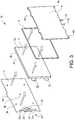
- Figures 1-6show a first embodiment of a battery pack 1 according to the invention, wherein figure 1 shows a front perspective view; figure 2 shows a rear perspective view; figure 3 shows the parts forming part of a repeating battery pack unit 10 of the battery pack 1; figure 4 the repeating battery pack unit 10 in an assembled state; figure 5 shows the structure and function of a cooling system of the battery pack; and figure 6 shows a sectional view of a part of the battery pack 1.
- the exemplified battery pack 1comprises a plurality of repeating battery pack units 10 (see figures 3-4 ).
- Each battery pack unit 10forms a layered structure comprising one battery cell 2, one circuit carrying sheet 3 and one cooling plate 4 ( figure 3 ) arranged side by side, wherein the cell 2 is arranged in-between the circuit carrying sheet 3 and the cooling plate 4.
- Each battery pack unit 10also comprises an elastic sealing frame 8 extending along the edge 2c of the cell 2 that holds the cell 2 in place inside a peripheral region of the cooling plate 4 that has an increased thickness ( figures 3 , 4 and 6 ).
- the battery pack 1 shown in figure 1is an assembly of around thirty battery pack units 10 where the battery cells 2 are electrically connected in series.
- the battery pack 1also includes an end cooling plate 4b.
- the battery pack 1has a main cathode (power-minus) 5 and a main anode (power-plus) 6 to which appropriate equipment (not shown) can be connected.
- the battery cells 2are substantially flat with two opposite sides 2a, 2b and a peripheral edge 2c ( figure 3 ).
- the battery cells 2are arranged side by side with their substantially flat sides 2a, 2b facing each other and form together with the circuit carrying sheets 3 and the cooling plates 4 a layered sandwich structure.
- Each battery cell 2comprises a cell anode and a cell cathode.
- First and second foldable cell power tabs 21, 22are connected to the cell anode and cathode, respectively, and protrude at the edge of the battery cell 2.
- the cell power tabs 21, 22are folded and connected by welding to corresponding power tabs of adjacent cells 2 as to connect the battery cells 2 electrically to each other, in this case serially.
- An electronic arrangement configured to monitor and control the battery cellsis realized in the form of a plurality of individual electronic circuit units 30 arranged on each of the circuit carrying sheet 3.
- Each of the electronic circuit units 30is thus associated with a corresponding battery cell 2 and is configured to be capable of monitoring and controlling its corresponding battery cell 2.
- the circuit carrying sheet 3is thin and flexible and is fastened by means of a self-adhesive layer to one of the sides 2c of the corresponding battery cell 2.
- Figure 3shows a schematic view of the electronic circuit unit 30 arranged on the circuit carrying sheet 3.
- first and second power connection tabs 31 a, 31 ba control unit 35 in the form of a function logic state machine, typically comprising a CPU (Central Processing Unit) or an ASIC (Application Specific Integrated Circuit), a plurality of temperature sensors 36, first and second foldable communication tabs 32, 33 and a resistive balance circuit/tab 34.
- Further components that may form part of the electronic circuit unit 30are, for instance, a pressure sensor and/or a heating member capable of heating the corresponding cell 2. Connections between the components, in particular connections from and to the control unit 35, are not shown.
- figure 3is schematic and in reality the electronic circuit unit 30 may not be visible on the side of the circuit carrying sheet 3 displayed in figure 3 .
- All components and connections of the electronic circuit unit 30are arranged on the flexible circuit carrying sheet 3 and covered with a protection layer.
- the circuit carrying sheet 3is in this case provided with an adhesive layer for attachment to the corresponding battery cell 2.
- Part of the power connection tabs 31 a, 31 b and the communication tabs 32, 33are provided with bare contact surfaces in order to simplify electric connection to the first and second foldable cell power tabs 21, 22 of the corresponding cell 2 and to corresponding communication tabs of adjacent battery pack units 10, respectively.
- the tabs of adjacent battery pack units 10are folded and welded together.
- Each electronic circuit unit 30is capable of measuring the voltage and the temperature of the corresponding battery cell 2 as well as of controlling the operation of the corresponding cell 2 based on the voltage and temperature measurements. This is possible because the electronic circuit unit 30 comprises the control unit 35 that is connected to the cell anode and cathode (via the power connection tabs 31 a, 31 b and the cell power tabs 21, 22) and to the at least one temperature sensor 36, wherein the control unit 35 is capable, by means that are known as such, of measuring the voltage and the temperature of the corresponding battery cell 2 as well as of controlling the operation of the corresponding cell 2 based on voltage and temperature measurements.
- Each electronic circuit unit 30is in this case also capable of communicating with the other electronic circuit units 30 of the battery pack 1 (and/or with further, not shown, equipment communicatively connected to the electronic circuit unit 30).
- the control unit 35controls also the communication and the electronic circuit units 30 are connected via the communication tabs 32, 33 that are connected to the control unit 35 of the corresponding electronic circuit unit 30.
- the communication tabs 32, 33protrude at an edge of the circuit carrying sheet 3 and the communication tabs 32, 33 are folded and connected to corresponding communication tabs of adjacent electronic circuit units 30.
- the electronic circuit units 30can only measure voltage and temperature, and e.g. pressure if such a sensor is included, related to their associated battery cell 2, and they can only base their control of its associated cell 2 on these locally determined data. Although this may be sufficient in some applications, it is normally an advantage if the operation of a particular cell can be based on information on the other cells of the battery pack.
- the cells 2 of the inventive battery pack 1may be connected to a central communication unit that communicate with all the cells, as in for instance US 7479786 . However, by making each electronic circuit unit 30 capable of communicating with the other cells 2 no such central unit is required.
- each electronic circuit unit 30communicates with all other electronic circuit unit 30 and receives thereby information on the other cells 2 as well as sends information on its associated cell 2 to the other electronic circuit units 30.
- Predetermined action routines in each of the electronic circuit units 30, i.e. in each of the control units 35, for controlling the associated cell 2can thus be based on the conditions of all cells 2 in the battery pack 1.
- the BMS of the present inventionmay be denoted a distributed BMS.
- Main functions of a BMSare to balance the cells, i.e. to keep the energy content among the cells relatively even, and to estimate the SOC (state of charge). Since the SOC typically is a function of temperature, cell voltage and the current through the battery pack, the battery pack 1 preferably comprises a current sensor arranged in communication with the electronic circuit units 30.
- the individual electronic circuit units 30can operate independently of each other. Alternatively, one or several of the electronic circuit units 30 can be used as a "master" unit that at least partly controls other electronic circuit units 30.
- a further feature of the battery pack 1is that electrical power connections to each electronic circuit unit 30, to each control unit 35, are arranged both from its corresponding battery cell 2 as well as from at least one additional battery cell, preferably from 3-5 adjacent battery cells. This way it is possible to handle cell failures. If there is no power back-up system the electronic circuit unit 30 of a certain battery pack unit 10 is not capable of communicating a cell failure. These power connections are realized by a number of additional connections that transfer power via the communication tabs 32, 33.
- the circuit carrying sheet 3extends over the side 2b of the battery cell, and in this example the circuit carrying sheet 3 has substantially the same size as its corresponding battery cell 2.
- the control unit 35is arranged in the vicinity of the edge 2c of the battery cell 2 whereas at least one of the temperature sensors 36 is arranged at a distance from the control unit 35 in a central region of the battery cell 2.
- the control unit 35can be placed close to the tabs 31 a, 31 b, 32, 33, which shortens the connections to the control unit 35, whereas the temperature sensor 36 can be placed as to give a better representation of the temperature of the battery cell 2.
- several temperature sensorsare distributed over the surface of the cell 2 which gives an improved monitoring of the cell temperature.
- a depression in the battery cell 2at a position corresponding to that of the control unit 35 it can be avoided that this relatively sensitive component becomes subjected to a large pressure between the corresponding cell 2 and the cooling plate 4 of an adjacent battery pack unit 10 positioned on the other side (the rear side in figure 4 ) of the circuit carrying sheet 3.
- Such a depressionmay instead, or also, be arranged in the cooling plate 4 of the adjacent battery pack unit 10.
- the electronic circuit unit 30comprises a resistive balance circuit (not shown) controlled by the control unit 35.
- the resistive balance circuitcomprises a resistive copper wiring arranged in the resistive balance tab 34 that protrudes at an edge of the circuit carrying sheet 3 and that is folded around an edge of an adjacent cooling plate to provide for effective cooling.
- the electronic circuit unit 30is configured such that an electric current from the corresponding battery cell 2 can be tapped off via the resistive balance circuit such as to lower the voltage of the cell 2. This is form of passive balancing of the battery cell 2.
- the electronic circuit units 30may also comprise means for active balancing. In such balancing the energy is transferred via the communication tabs 32, 33.
- the electronic circuit unit 30may also comprise a controllable heating member capable of heating the corresponding cell 2.
- Thiscan be a copper wiring similar to the resistive balance circuit but arranged as to extend over the circuit carrying sheet 3 and thus over the side 2b of the corresponding cell 2 such as to effectively heat the cell 2 if needed.
- the electronic circuit unit 30may also comprise a pressure sensor so that the control unit 35 can detect, and communicate, deviations from normal pressure that, for instance, can occur if the battery pack units 10 expand due to malfunction or abuse.
- circuit carrying sheets 3Flexible films for use as circuit carrying sheets 3 are known as such. Also the components used on each circuit carrying sheet 3 are known as such.
- a further feature of the inventive battery pack 1is that the communication bus, i.e. the bus formed by the connected communication tabs 32, 33, is insulated from the battery pack 1.
- the internal cell communicationis thus realized with an electronic bus, the potential of which is insulated from the potential of the individual cells. This way the internal communication bus can be connected to the battery bus of the vehicle or machine in which the battery pack is installed.
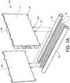
- Each cooling plate 4is provided with an internal cooling channel 41 that extends along the edge of the cooling plate in the peripheral region where the thickness of the cooling plate 4 is larger (see figure 6 ).
- the cooling channel 41has an inlet 43 and an outlet 42 in the form of protruding pipe ends arranged on the edge of the cooling plate 4 at an underside thereof.
- the inlet 43is connected to a cooling medium supply 16 that extends along the underside of the battery pack 1 and the outlet 42 is connected to a cooling medium discharge 15 that extends in parallel with the cooling medium supply 16 on the same side of the battery pack 1.
- Connection pipes 17, 18, in this example bent connection pipes,form connections between the inlet/outlet 43/42 and the cooling medium supply/discharge 16/17.
- a suitable cooling mediumis water.
- connection pipes 17, 18 and the cooling medium supply/discharge 16/15can be arranged in different ways. An important thing is that all connections are leak-proof and to simplify manufacturing it should be easy to make the connections leak-proof. In this case sealing is made by welding or using adhesives.
- cooling medium supply/discharge 16/17as a supporting and positioning unit that extends along the length of the battery pack 1 to be manufactured.
- manufacturingis simplified. In this case this is achieved by using inlets/outlets 43, 42 in the form of pipe ends that protrude from the edge of the cooling plate 4 in a direction parallel to the layers in the layered battery pack 1, and by inserting these pipe ends into the connection pipes 17, 18 (see figures 7A and 7B ).
- the cooling plates 4are provided with protrusions 48 that are used for supporting the battery pack 1 when arranged in a casing (not shown).
- Each cooling plate 4is provided with a plurality of through-holes 46 positioned outside of the peripheral edge 2c of the battery cells 2.
- the holes 46are placed in one of the protrusions 48 located outside of the cooling channel 41 at each corner of the cooling plate 4.
- Straight connection rods 47extend in a direction perpendicular to the plane of the layers in the layered battery pack 1 through corresponding through-holes 46 of the cooling plates 4 (and the end cooling plate 4b) from a first end of the battery pack 1, at the end cooling plate 4b, to a second end, at the battery pack unit 10 opposite to the end cooling plate 4b.
- Locking devices 49are arranged at each of said ends of the battery pack 1 at each end part of the connection rods 47 to hold the connection rods 47 in place and to press the layers together in the battery pack 1.
- the locking device 49comprises a compression coil spring 49a that is slipped onto the end part of the connection rod 47 and a screw nut 49b that is screwed onto threads provided on the end part of the connection rod 47 such as to compress the coil spring 49a and thereby press the layered battery pack 1 together.
- a compression coil spring 49athat is slipped onto the end part of the connection rod 47 and a screw nut 49b that is screwed onto threads provided on the end part of the connection rod 47 such as to compress the coil spring 49a and thereby press the layered battery pack 1 together.
- the spring 49aallows for some movement and expansion of the battery pack units 10, for instance induced by increased temperature.
- a suitable material for the cooling plates 4is aluminium.
- inventive battery pack 1can be used in most applications it is particularly useful for high-power applications, such as powering of electric or hybrid vehicles. Such applications generally require special arrangements for handling of the heat evolved by the cells 2, in contrast to small battery pack applications for e.g. computers. Also the method of manufacturing the battery pack differs considerably between large, high-power packs and smaller packs.
- the battery cells 2are preferably of the Li-ion type and each battery cell 2 has a capacity of at least 1 Ah, typically at least 10 Ah.
- the battery pack 1has typically a capacity of at least 200 Wh; likely output values are 2-50 kWh and 12-400 V.
- Figure 7A-7Cshow steps of the process of assembling the battery pack shown in figures 1-6 .
- Figures 3-4show the step of assembling one of the battery pack units 10 forming part of the battery pack 1.
- step of forming a repeating battery pack unit 10comprises in this example the steps of:
- the above stepsmay be carried out in a different order and part or all of them may alternatively be carried out when the cooling plate 4 is already arranged in the battery pack 1, i.e. when supported and positioned by the cooling medium supply/discharge 16/15.
- the method for manufacturing of the battery pack 1 stepcomprises in this example the steps of:
- the main stepscan be regarded to be the step of forming a plurality of repeating battery pack units 10 of the type described above (which step can be carried out in different ways as described above), and the step of assembling said plurality of repeating battery pack units 10 as to form the battery pack 1.
- a step that simplifies the production methodis that each cooling plate 4 can be firmly connected to the cooling medium supply and discharge system which holds the cooling plate 4 or the battery cell unit 10 in place and thereby has a supporting and positioning function.
- the inventionis not limited by the embodiments described above but can be modified in various ways within the scope of the claims. For instance, it is not necessary to provide the cooling plates with internal cooling channels or to make use of a circulating cooling medium in the battery pack.
- the coolingcan instead be based on air-cooling of the cooling plates.
- Various types of cooling fins and/or internal air channelscan be arranged onto/in the cooling plates.
- pressure sensorsare included these are also connected to the control unit 35. This makes it possible to determine possible cell expansion at an early stage and thereby identify possible mal-function in time to avoid serious problems.
Landscapes
- Engineering & Computer Science (AREA)
- Chemical & Material Sciences (AREA)
- Chemical Kinetics & Catalysis (AREA)
- Electrochemistry (AREA)
- General Chemical & Material Sciences (AREA)
- Manufacturing & Machinery (AREA)
- Microelectronics & Electronic Packaging (AREA)
- Materials Engineering (AREA)
- Secondary Cells (AREA)
- Battery Mounting, Suspending (AREA)
Description
- This invention relates to a rechargeable battery pack for use as electrical power source in, for instance, electrical or hybrid vehicle applications. The invention also relates to a method for manufacturing of such a battery pack.
- There is a general need for efficient rechargeable battery packs for use as electrical power source in, for instance, electrical or hybrid vehicle applications. Besides being capable of delivering an adequate electrical power, such battery packs must be safe with regard to operation and recharging, and ideally they should further have a long-time durability and rechargeability, occupy as little space as possible, allow for an easy and cost-effective production, etc.
- Typically, such battery packs contain a number of battery cells connected in series and/or parallel, an electronic arrangement for monitoring and controlling the cells, and a system for cooling the cells. The electronic arrangement typically includes a PCB (printed circuit board) connected to the cells and a BMS (battery management system) capable of balancing the cells and estimating the state of charge (SOC). Commonly, thin and flat (prismatic) Li-ion type cells are used.
US 7479786 is directed to a member for measurement of cell voltage and temperature in a battery pack and discloses a design where a specially shaped PCB is electrically connected to serially connected unit cells as well as to temperature measuring elements attached to the surfaces of the unit cells. The PCB is further connected to a central BMS at which voltage and temperature measuring devices are mounted. An advantage of this design is stated to be the reduced need of external wiring members for connecting the cells to the voltage and temperature measuring devices.US 2011/0274956 shows another example of a battery pack including sandwiched flat cells and cooling fins where a weld-free, frameless battery stack design is disclosed. This design is stated to simplify assembling and dissembling of the battery pack. No particular solution is disclosed regarding the electronic arrangement.- No fully satisfying battery pack for e.g. electrical or hybrid vehicle applications appears yet to have been presented so there is still a need for improvements.
- An object of this invention is to provide a battery pack of the above type that has a more compact and simple structure compared to conventional battery packs and that allows for an efficient and flexible manufacturing. This object is achieved by the battery pack defined by the technical features contained in independent claim 1. Another object is to provide an improved method of manufacturing a battery pack. The dependent claims contain advantageous embodiments, further developments and variants of the invention.
- The invention concerns a battery pack comprising a plurality of electrically connected battery cells, wherein the battery cells are substantially flat with two opposite sides and a peripheral edge, and wherein the battery cells are arranged side by side as to form a layered structure, and an electronic arrangement configured to monitor and control the battery cells.
- The invention is characterized in that the electronic arrangement comprises a plurality of individual electronic circuit units, each of which being associated with a corresponding battery cell, wherein each of the electronic circuit units is configured to be capable of monitoring and controlling its corresponding battery cell, and wherein each electronic circuit unit is arranged on a thin and flexible circuit carrying sheet that is arranged at one of the sides of the corresponding battery cell.
- A battery pack design according to the invention has several advantages. The use of individual electronic circuit units dispenses with the need of arranging a central BMS as well as of arranging connection members required for connecting sensors etc. with such a central BMS. Further, using such intelligent electronics distributed at each battery cell provides for the possibility of letting the individual electronic circuit units communicate with each other, for instance via a bus member or superimposed on the power connections between the cells, so as to form a distributed BMS.
- The circuit carrying sheet can, for instance, be a flexible film having a layer provided with electronic circuits and components, terminals, sensors, cupper connectors etc. covered with a protective layer. To arrange electronic circuits on flexible films as to form "flexi-PCB's" is known as such. How to make an electronic circuit unit capable of monitoring and controlling a battery cell is also known as such. The thin, flexible sheet can be provided with a self-adhesive layer and simply be attached to the flat side of the cell. A part of the sheet including part of the electronic circuit unit can extend outside an edge of the cell so as to simplify electric connection to the electronic circuit unit. Preferably, the sheet extends over a considerable portion of the side of the cell so that a temperature sensor forming part of the circuit unit can be positioned approximately in the middle of the cell or so that several temperature sensors can be distributed over the side of the cell. A sheet that extends over the side of the cell also allows further components to be included in the electronic circuit unit.
- Besides attaching the sheet by adhesive means, the electronic circuit unit may form an integrated part of the battery cell, i.e. the sheet containing the electronic circuit unit may form an integrated part of the cell. For instance, the electronic circuit unit may be arranged in a cell protection cover or be arranged inside of such a cover. A further possibility is to simply clamp the sheet between two cells or other components of the battery stack and hold it in place simply by friction. Electric connection between the circuit unit and the anode and cathode of the corresponding cell can be arranged in different ways. Sensitive parts of the electronic circuit unit, such as a control unit including a CPU or an ASIC, are preferably positioned in such a way as to avoid getting pressed together (too much) between its corresponding cell and an adjacent part of the battery pack, for instance by providing a depression in the surface of the cell or the adjacent part at a position corresponding to that of the sensitive electronic parts.
- A further advantage of positioning the flexible sheets between the battery cells is that it makes the battery pack more tolerant towards impacts and vibrations. Since the sheet is thin it still allows cooling of the battery cell from both sides, for instance by incorporating flat cooling plates between the cells.
- By arranging electronic circuit units of the type described above on the side of each battery cell manufacturing of the battery pack is simplified because there is no need to install any stiff conventional PCB's, cables or other external electronic equipment at the cells for the purpose of establishing a connection from the cells to a central BMS or temperature measurement device. Thus, the use of individual electronic circuit units arranged on thin, flexible sheets arranged at the cell sides provides for an efficient manufacturing of a compact and space-saving battery pack. Further, the manufacturing becomes flexible in that it is possible to select and connect a suitable, optional number of battery cells units to each other.
- In an embodiment of the invention the battery pack comprises a plurality of cooling plates arranged as layers between battery cells in the layered structure. Preferably, the battery pack comprises a plurality of repeating battery pack units, each battery pack unit forming a layered structure comprising one of said battery cells, one of said circuit carrying sheets and one of said cooling plates. Such a battery pack can be cooled efficiently and provides for an efficient manufacture.
- In an embodiment of the invention the cooling plates are provided with an internal cooling channel with an inlet and an outlet, wherein the inlet is connected to a cooling medium supply and wherein the outlet is connected to a cooling medium discharge.
- In an embodiment of the invention each cooling plate is provided with a plurality of through-holes positioned outside of the peripheral edge of the battery cells, wherein a connection rod extends through corresponding through-holes of the cooling plates from a first end of the battery pack to a second end, wherein a locking device at each of said ends of the battery pack is arranged to hold the connection rod in place and to press the layers together in the battery pack. This arrangement holds the battery pack together and provides for an efficient assembling of the pack.
- In an embodiment of the invention each battery cell comprises a cell anode and a cell cathode, wherein first and second foldable cell power tabs are connected to the cell anode and cathode, respectively, wherein said cell power tabs protrude at the edge of the battery cell. Such power tabs can easily be folded and fixed, e.g. by welding, after assembling of the battery pack. Preferably, the foldable cell power tabs are folded and connected to adjacent cells as to connect the battery cells electrically to each other.
- In an embodiment of the invention each battery cell comprises a cell anode and a cell cathode, wherein each of the electronic circuit units is electrically connected to the cell anode and cathode of its corresponding cell. Each electronic circuit unit is capable of measuring the voltage and the temperature of the corresponding battery cell as well as of controlling the operation of the corresponding cell based on the voltage and temperature measurements.
- In an embodiment of the invention each electronic circuit unit comprises a control unit and at least one temperature sensor connected to the control unit, wherein the control unit is capable of measuring the voltage and the temperature of the corresponding battery cell as well as of controlling the operation of the corresponding cell based on the voltage and temperature measurements.
- In an embodiment of the invention the circuit carrying sheet extends over the side of the battery cell, wherein the control unit is arranged in the vicinity of the edge of the battery cell whereas the temperature sensor is arranged at a distance from the control unit in a central region of the battery cell. This gives easy access to the control unit whereas the temperature sensor is positioned where a higher temperature can be expected.
- In an embodiment of the invention each electronic circuit unit comprises a controllable heating member capable of heating the corresponding cell. This is useful in applications where there is a risk that the temperature is too low.
- In an embodiment of the invention each electronic circuit unit comprises a resistive balance circuit, wherein the electronic circuit unit is configured such that an electric current from the corresponding battery cell can be tapped off via the resistive balance circuit such as to lower the voltage of the cell. This way passive balancing can be performed. Preferably, the resistive balance circuit is arranged in a resistive balance tab that protrudes at an edge of the circuit carrying sheet, wherein the resistive balance tab is folded around an edge of an adjacent cooling plate. This provides for an efficient cooling of the resistive balance circuit which in turn provides for an efficient balancing.
- In an embodiment of the invention the electronic circuit units are connected such as to allow communication between the electronic circuit units of the battery pack. By allowing such a communication no central control unit is required. Instead, each electronic circuit unit can communicate with all other electronic circuit unit and can thereby receive information on the other cells as well as send information on its associated cell to the other electronic circuit units. Predetermined action routines in each of the electronic circuit units for controlling the associated cell can thus be based on the conditions of all cells in the battery pack. Such a BMS may be denoted a distributed BMS.
- In an embodiment of the invention each circuit carrying sheet comprises first and second foldable communication tabs connected to the corresponding electronic circuit unit, wherein said communication tabs protrude at an edge of the circuit carrying sheet, wherein the communication tabs are folded and connected to adjacent electronic circuit units. This is a suitable way of achieving such an internal communication between the electronic circuit units.
- In an embodiment of the invention the electronic circuit unit comprises a pressure sensor. This can be used to detect cell-expansion and possible malfunction at an early stage.
- In an embodiment of the invention electrical power connections to each electronic circuit unit are arranged both from its corresponding battery cell as well as from at least one additional battery cell. This way the electronic circuit unit of a particular cell can still function even if its associated cell does not provide it with sufficient power.
- In an embodiment of the invention the circuit carrying sheet has substantially the same size as its corresponding battery cell. This way various components of the electronic circuit unit can be distributed properly over the side of the cell.
- In an embodiment of the invention the circuit carrying sheet is attached to its corresponding battery cell by adhesive means. Preferably, the sheet is provided with a self-adhesive layer. This simplifies manufacture.
- In an embodiment of the invention the cells are of the Li-ion type with a capacity of at least 1 Ah each.
- The invention also concerns a method for manufacturing of a battery pack comprising: a plurality of electrically connected battery cells, wherein the battery cells are substantially flat with two opposite sides and a peripheral edge; and a plurality of cooling plates, wherein the battery cells and the cooling plates are arranged side by side as to form a layered structure, said battery pack further comprising an electronic arrangement configured to monitor and control the battery cells.
- The method is characterized in that it comprises the steps of: forming a plurality of repeating battery pack units, wherein each battery pack unit forms a layered structure comprising one of said battery cells, one of said cooling plates and a thin and flexible circuit carrying sheet arranged at one of the sides of a corresponding battery cell, said circuit carrying sheet comprising an electronic circuit unit being capable of monitoring and controlling its corresponding battery cell; and assembling said plurality of repeating battery pack units as to form the battery pack.
- In embodiments of the inventive method it comprises one or several of the following steps:
- attaching the circuit carrying sheet to the corresponding battery cell by adhesive means;
- connecting the electronic circuit unit to the corresponding battery cell by connecting first and second power connection tabs, that form part of the electronic circuit unit and the circuit carrying sheet, with foldable first and second foldable cell power tabs that are connected to a cell anode and a cell cathode, respectively;
- establishing a communication arrangement allowing the electronic circuit units in the battery pack to communicate with each other;
- connecting first and second foldable communication tabs that protrude at an edge of the circuit carrying sheet to corresponding communication tabs of adjacent electronic circuit units.
- In the description of the invention given below reference is made to the following figure, in which:
- Figure 1
- shows, in a perspective view, a front side of a first embodiment of a battery pack according to the invention,
- Figure 2
- shows, in a perspective view, a rear side of the battery pack according to
figure 1 , - Figure 3
- shows the parts forming part of a repeating battery pack unit of the battery pack shown in
figure 1 , - Figure 4
- shows, in an assembled state, the repeating battery pack unit of
figure 3 , - Figure 5
- shows the structure and function of a cooling system of the battery pack of
figure 1 , - Figure 6
- shows a sectional view of a part of the battery pack of
figure 1 , - Figure 7A
- shows a step of the process of assembling a battery pack according to
figure 1 , - Figure 7B
- shows a further step of the process of assembling a battery pack according to
figure 1 , and - Figure 7C
- shows a still further step of the process of assembling a battery pack according to
figure 1 . Figures 1-6 show a first embodiment of a battery pack 1 according to the invention, whereinfigure 1 shows a front perspective view;figure 2 shows a rear perspective view;figure 3 shows the parts forming part of a repeatingbattery pack unit 10 of the battery pack 1;figure 4 the repeatingbattery pack unit 10 in an assembled state;figure 5 shows the structure and function of a cooling system of the battery pack; andfigure 6 shows a sectional view of a part of the battery pack 1.- As can be seen in
figures 1-6 the exemplified battery pack 1 comprises a plurality of repeating battery pack units 10 (seefigures 3-4 ). Eachbattery pack unit 10 forms a layered structure comprising onebattery cell 2, onecircuit carrying sheet 3 and one cooling plate 4 (figure 3 ) arranged side by side, wherein thecell 2 is arranged in-between thecircuit carrying sheet 3 and thecooling plate 4. Eachbattery pack unit 10 also comprises anelastic sealing frame 8 extending along theedge 2c of thecell 2 that holds thecell 2 in place inside a peripheral region of thecooling plate 4 that has an increased thickness (figures 3 ,4 and6 ). - The battery pack 1 shown in
figure 1 is an assembly of around thirtybattery pack units 10 where thebattery cells 2 are electrically connected in series. The battery pack 1 also includes anend cooling plate 4b. The battery pack 1 has a main cathode (power-minus) 5 and a main anode (power-plus) 6 to which appropriate equipment (not shown) can be connected. - The
battery cells 2 are substantially flat with twoopposite sides 2a, 2b and aperipheral edge 2c (figure 3 ). Thebattery cells 2 are arranged side by side with their substantiallyflat sides 2a, 2b facing each other and form together with thecircuit carrying sheets 3 and the cooling plates 4 a layered sandwich structure. - Each
battery cell 2 comprises a cell anode and a cell cathode. First and second foldablecell power tabs battery cell 2. Thecell power tabs adjacent cells 2 as to connect thebattery cells 2 electrically to each other, in this case serially. - An electronic arrangement configured to monitor and control the battery cells is realized in the form of a plurality of individual
electronic circuit units 30 arranged on each of thecircuit carrying sheet 3. Each of theelectronic circuit units 30 is thus associated with acorresponding battery cell 2 and is configured to be capable of monitoring and controlling its correspondingbattery cell 2. Thecircuit carrying sheet 3 is thin and flexible and is fastened by means of a self-adhesive layer to one of thesides 2c of thecorresponding battery cell 2. Figure 3 shows a schematic view of theelectronic circuit unit 30 arranged on thecircuit carrying sheet 3. What is indicated infigure 3 is first and secondpower connection tabs control unit 35 in the form of a function logic state machine, typically comprising a CPU (Central Processing Unit) or an ASIC (Application Specific Integrated Circuit), a plurality oftemperature sensors 36, first and secondfoldable communication tabs tab 34. Further components that may form part of theelectronic circuit unit 30 are, for instance, a pressure sensor and/or a heating member capable of heating thecorresponding cell 2. Connections between the components, in particular connections from and to thecontrol unit 35, are not shown. It should be noted thatfigure 3 is schematic and in reality theelectronic circuit unit 30 may not be visible on the side of thecircuit carrying sheet 3 displayed infigure 3 .- All components and connections of the
electronic circuit unit 30 are arranged on the flexiblecircuit carrying sheet 3 and covered with a protection layer. Thecircuit carrying sheet 3 is in this case provided with an adhesive layer for attachment to thecorresponding battery cell 2. Part of thepower connection tabs communication tabs cell power tabs corresponding cell 2 and to corresponding communication tabs of adjacentbattery pack units 10, respectively. As further described below, the tabs of adjacentbattery pack units 10 are folded and welded together. - Each
electronic circuit unit 30 is capable of measuring the voltage and the temperature of thecorresponding battery cell 2 as well as of controlling the operation of thecorresponding cell 2 based on the voltage and temperature measurements. This is possible because theelectronic circuit unit 30 comprises thecontrol unit 35 that is connected to the cell anode and cathode (via thepower connection tabs cell power tabs 21, 22) and to the at least onetemperature sensor 36, wherein thecontrol unit 35 is capable, by means that are known as such, of measuring the voltage and the temperature of thecorresponding battery cell 2 as well as of controlling the operation of thecorresponding cell 2 based on voltage and temperature measurements. - Each
electronic circuit unit 30 is in this case also capable of communicating with the otherelectronic circuit units 30 of the battery pack 1 (and/or with further, not shown, equipment communicatively connected to the electronic circuit unit 30). Thecontrol unit 35 controls also the communication and theelectronic circuit units 30 are connected via thecommunication tabs control unit 35 of the correspondingelectronic circuit unit 30. Thecommunication tabs circuit carrying sheet 3 and thecommunication tabs electronic circuit units 30. - Without any communicational possibility, the
electronic circuit units 30 can only measure voltage and temperature, and e.g. pressure if such a sensor is included, related to their associatedbattery cell 2, and they can only base their control of its associatedcell 2 on these locally determined data. Although this may be sufficient in some applications, it is normally an advantage if the operation of a particular cell can be based on information on the other cells of the battery pack. Thecells 2 of the inventive battery pack 1 may be connected to a central communication unit that communicate with all the cells, as in for instanceUS 7479786 . However, by making eachelectronic circuit unit 30 capable of communicating with theother cells 2 no such central unit is required. In the embodiment of the invention described here, eachelectronic circuit unit 30 communicates with all otherelectronic circuit unit 30 and receives thereby information on theother cells 2 as well as sends information on its associatedcell 2 to the otherelectronic circuit units 30. Predetermined action routines in each of theelectronic circuit units 30, i.e. in each of thecontrol units 35, for controlling the associatedcell 2 can thus be based on the conditions of allcells 2 in the battery pack 1. The BMS of the present invention may be denoted a distributed BMS. - Main functions of a BMS are to balance the cells, i.e. to keep the energy content among the cells relatively even, and to estimate the SOC (state of charge). Since the SOC typically is a function of temperature, cell voltage and the current through the battery pack, the battery pack 1 preferably comprises a current sensor arranged in communication with the
electronic circuit units 30. In the inventive battery pack 1 the individualelectronic circuit units 30 can operate independently of each other. Alternatively, one or several of theelectronic circuit units 30 can be used as a "master" unit that at least partly controls otherelectronic circuit units 30. - A further feature of the battery pack 1 is that electrical power connections to each
electronic circuit unit 30, to eachcontrol unit 35, are arranged both from its correspondingbattery cell 2 as well as from at least one additional battery cell, preferably from 3-5 adjacent battery cells. This way it is possible to handle cell failures. If there is no power back-up system theelectronic circuit unit 30 of a certainbattery pack unit 10 is not capable of communicating a cell failure. These power connections are realized by a number of additional connections that transfer power via thecommunication tabs - As can be seen in
figures 3-4 thecircuit carrying sheet 3 extends over theside 2b of the battery cell, and in this example thecircuit carrying sheet 3 has substantially the same size as its correspondingbattery cell 2. Thecontrol unit 35 is arranged in the vicinity of theedge 2c of thebattery cell 2 whereas at least one of thetemperature sensors 36 is arranged at a distance from thecontrol unit 35 in a central region of the battery cell 2.This way thecontrol unit 35 can be placed close to thetabs control unit 35, whereas thetemperature sensor 36 can be placed as to give a better representation of the temperature of thebattery cell 2. In this case several temperature sensors are distributed over the surface of thecell 2 which gives an improved monitoring of the cell temperature. - By arranging a depression in the
battery cell 2 at a position corresponding to that of thecontrol unit 35 it can be avoided that this relatively sensitive component becomes subjected to a large pressure between thecorresponding cell 2 and thecooling plate 4 of an adjacentbattery pack unit 10 positioned on the other side (the rear side infigure 4 ) of thecircuit carrying sheet 3. Such a depression may instead, or also, be arranged in thecooling plate 4 of the adjacentbattery pack unit 10. - The
electronic circuit unit 30 comprises a resistive balance circuit (not shown) controlled by thecontrol unit 35. The resistive balance circuit comprises a resistive copper wiring arranged in theresistive balance tab 34 that protrudes at an edge of thecircuit carrying sheet 3 and that is folded around an edge of an adjacent cooling plate to provide for effective cooling. Theelectronic circuit unit 30 is configured such that an electric current from the correspondingbattery cell 2 can be tapped off via the resistive balance circuit such as to lower the voltage of thecell 2. This is form of passive balancing of thebattery cell 2. Theelectronic circuit units 30 may also comprise means for active balancing. In such balancing the energy is transferred via thecommunication tabs - The
electronic circuit unit 30 may also comprise a controllable heating member capable of heating thecorresponding cell 2. This can be a copper wiring similar to the resistive balance circuit but arranged as to extend over thecircuit carrying sheet 3 and thus over theside 2b of thecorresponding cell 2 such as to effectively heat thecell 2 if needed. - The
electronic circuit unit 30 may also comprise a pressure sensor so that thecontrol unit 35 can detect, and communicate, deviations from normal pressure that, for instance, can occur if thebattery pack units 10 expand due to malfunction or abuse. - Flexible films for use as
circuit carrying sheets 3 are known as such. Also the components used on eachcircuit carrying sheet 3 are known as such. - A further feature of the inventive battery pack 1 is that the communication bus, i.e. the bus formed by the connected
communication tabs - Each
cooling plate 4 is provided with aninternal cooling channel 41 that extends along the edge of the cooling plate in the peripheral region where the thickness of thecooling plate 4 is larger (seefigure 6 ). The coolingchannel 41 has aninlet 43 and anoutlet 42 in the form of protruding pipe ends arranged on the edge of thecooling plate 4 at an underside thereof. Theinlet 43 is connected to a coolingmedium supply 16 that extends along the underside of the battery pack 1 and theoutlet 42 is connected to a coolingmedium discharge 15 that extends in parallel with the coolingmedium supply 16 on the same side of the battery pack 1.Connection pipes outlet 43/42 and the cooling medium supply/discharge 16/17. A suitable cooling medium is water. - The inlet and
outlets connection pipes discharge 16/15 can be arranged in different ways. An important thing is that all connections are leak-proof and to simplify manufacturing it should be easy to make the connections leak-proof. In this case sealing is made by welding or using adhesives. - With regard to manufacturing it is an advantage to use the cooling medium supply/
discharge 16/17 as a supporting and positioning unit that extends along the length of the battery pack 1 to be manufactured. By designing cooling connections and fittings so that individualbattery pack units 10 connected to the cooling medium supply/discharge 16/17 are hold in place, one by one, manufacturing is simplified. In this case this is achieved by using inlets/outlets cooling plate 4 in a direction parallel to the layers in the layered battery pack 1, and by inserting these pipe ends into theconnection pipes 17, 18 (seefigures 7A and7B ). - The
cooling plates 4 are provided withprotrusions 48 that are used for supporting the battery pack 1 when arranged in a casing (not shown). - Each
cooling plate 4 is provided with a plurality of through-holes 46 positioned outside of theperipheral edge 2c of thebattery cells 2. In this case theholes 46 are placed in one of theprotrusions 48 located outside of the coolingchannel 41 at each corner of thecooling plate 4.Straight connection rods 47 extend in a direction perpendicular to the plane of the layers in the layered battery pack 1 through corresponding through-holes 46 of the cooling plates 4 (and theend cooling plate 4b) from a first end of the battery pack 1, at theend cooling plate 4b, to a second end, at thebattery pack unit 10 opposite to theend cooling plate 4b. Lockingdevices 49 are arranged at each of said ends of the battery pack 1 at each end part of theconnection rods 47 to hold theconnection rods 47 in place and to press the layers together in the battery pack 1. - The locking
device 49 comprises a compression coil spring 49a that is slipped onto the end part of theconnection rod 47 and a screw nut 49b that is screwed onto threads provided on the end part of theconnection rod 47 such as to compress the coil spring 49a and thereby press the layered battery pack 1 together. This way the battery pack 1 can be hold together but at the same time the spring 49a allows for some movement and expansion of thebattery pack units 10, for instance induced by increased temperature. - A suitable material for the
cooling plates 4 is aluminium. - Although the inventive battery pack 1 can be used in most applications it is particularly useful for high-power applications, such as powering of electric or hybrid vehicles. Such applications generally require special arrangements for handling of the heat evolved by the
cells 2, in contrast to small battery pack applications for e.g. computers. Also the method of manufacturing the battery pack differs considerably between large, high-power packs and smaller packs. - The
battery cells 2 are preferably of the Li-ion type and eachbattery cell 2 has a capacity of at least 1 Ah, typically at least 10 Ah. The battery pack 1 has typically a capacity of at least 200 Wh; likely output values are 2-50 kWh and 12-400 V. Figure 7A-7C show steps of the process of assembling the battery pack shown infigures 1-6 .Figures 3-4 show the step of assembling one of thebattery pack units 10 forming part of the battery pack 1.- With reference to
figures 3-4 the step of forming a repeatingbattery pack unit 10 comprises in this example the steps of: - attaching the
circuit carrying sheet 3 to theside 2b of thecorresponding battery cell 2 by adhesive means, - placing the elastic frame sealing 8 onto the
cooling plate 4 inside the thicker peripheral region thereof, - placing the
battery cell 2 closely beside thecooling plate 4 inside of the frame sealing 8 (that at his stage is slightly compressed and holds thecell 2 in place). - The above steps may be carried out in a different order and part or all of them may alternatively be carried out when the
cooling plate 4 is already arranged in the battery pack 1, i.e. when supported and positioned by the cooling medium supply/discharge 16/15. - With reference to
figures 7A-7C the method for manufacturing of the battery pack 1 step comprises in this example the steps of: - providing and positioning a cooling medium system comprising cooling medium supply and
discharge connection pipes - positioning the
end cooling plate 4b by connecting itsinlet 43 andoutlet 42 to thecorresponding connection pipes - forming a first of said repeating
battery pack unit 10, - positioning said first
battery pack unit 10 by connecting theinlet 43 andoutlet 42 of itscooling plate 4 to thecorresponding connection pipes - folding and fastening the
resistive balance tab 34 to an adjacent cooling plate 4 (in this case theend cooling plate 4b), - repeating the previous steps with a plurality of
battery pack units 10, - inserting the
connection rods 47 through the corresponding through-holes 46 and attaching thelocking devices 49, and - folding and connecting (by welding) the
cell power tabs power connection tabs communication tabs - This is a simple and efficient method of manufacturing a battery pack. The main steps can be regarded to be the step of forming a plurality of repeating
battery pack units 10 of the type described above (which step can be carried out in different ways as described above), and the step of assembling said plurality of repeatingbattery pack units 10 as to form the battery pack 1. - A step that simplifies the production method is that each cooling
plate 4 can be firmly connected to the cooling medium supply and discharge system which holds thecooling plate 4 or thebattery cell unit 10 in place and thereby has a supporting and positioning function. - Further advantages of the manufacturing method are mainly related to the fact that the electronics are arranged on the circuit carrying sheet 3 (easy fastening of the
sheet 3 to thecell 2, easy handling and connection of thepower connection tabs communication tabs - The invention is not limited by the embodiments described above but can be modified in various ways within the scope of the claims. For instance, it is not necessary to provide the cooling plates with internal cooling channels or to make use of a circulating cooling medium in the battery pack. The cooling can instead be based on air-cooling of the cooling plates. Various types of cooling fins and/or internal air channels can be arranged onto/in the cooling plates.
- If pressure sensors are included these are also connected to the
control unit 35. This makes it possible to determine possible cell expansion at an early stage and thereby identify possible mal-function in time to avoid serious problems.
Claims (20)
- Battery pack (1), comprising- a plurality of electrically connected battery cells (2), wherein the battery cells (2) are substantially flat with two opposite sides (2a, 2b) and a peripheral edge (2c), and wherein the battery cells (2) are arranged side by side as to form a layered structure, and- an electronic arrangement configured to monitor and control the battery cells (2),characterized in
that the electronic arrangement comprises a plurality of individual electronic circuit units (30), each of which being associated with a corresponding battery cell (2),
wherein each of the electronic circuit units (30) is configured to be capable of monitoring and controlling its corresponding battery cell (2), and
wherein each electronic circuit unit (30) is arranged on a thin and flexible circuit carrying sheet (3) that is arranged at one of the sides (2a, 2b) of the corresponding battery cell (2). - Battery pack (1) according to claim 1,
characterized in
that the battery pack comprises a plurality of cooling plates arranged as layers between battery cells in the layered structure. - Battery pack (1) according to claim 2,
characterized in
that the battery pack comprises a plurality of repeating battery pack units, each battery pack unit forming a layered structure comprising one of said battery cells, one of said circuit carrying sheets and one of said cooling plates. - Battery pack (1) according to claim 2 or 3,
characterized in
that the cooling plates are provided with an internal cooling channel with an inlet and an outlet, wherein the inlet is connected to a cooling medium supply and wherein the outlet is connected to a cooling medium discharge. - Battery pack (1) according to any one of claims 2 to 4,
characterized in
that each cooling plate is provided with a plurality of through-holes positioned outside of the peripheral edge of the battery cells, wherein a connection rod extends through corresponding through-holes of the cooling plates from a first end of the battery pack to a second end, wherein a locking device at each of said ends of the battery pack is arranged to hold the connection rod in place and to press the layers together in the battery pack. - Battery pack (1) according to any one of the above claims,
characterized in
that each battery cell comprises a cell anode and a cell cathode, wherein first and second foldable cell power tabs are connected to the cell anode and cathode, respectively, wherein said cell power tabs protrude at the edge of the battery cell. - Battery pack (1) according to claim 6,
characterized in
that the foldable cell power tabs are folded and connected to adjacent cells as to connect the battery cells electrically to each other. - Battery pack (1) according to any one of the above claims,
characterized in
that each battery cell comprises a cell anode and a cell cathode, wherein each of the electronic circuit units is electrically connected to the cell anode and cathode of its corresponding cell. - Battery pack (1) according to any one of the above claims,
characterized in
that each electronic circuit unit is capable of measuring the voltage and the temperature of the corresponding battery cell as well as of controlling the operation of the corresponding cell based on the voltage and temperature measurements. - Battery pack (1) according to any one of the above claims,
characterized in
that each electronic circuit unit comprises a control unit and at least one temperature sensor connected to the control unit, wherein the control unit is capable of measuring the voltage and the temperature of the corresponding battery cell as well as of controlling the operation of the corresponding cell based on the voltage and temperature measurements. - Battery pack (1) according to claim 10,
characterized in
that the circuit carrying sheet extends over the side of the battery cell, wherein the control unit is arranged in the vicinity of the edge of the battery cell whereas the temperature sensor is arranged at a distance from the control unit in a central region of the battery cell. - Battery pack (1) according to any one of the above claims,
characterized in
that each electronic circuit unit comprises a controllable heating member capable of heating the corresponding cell. - Battery pack (1) according to any one of the above claims,
characterized in
that each electronic circuit unit comprises a resistive balance circuit, wherein the electronic circuit unit is configured such that an electric current from the corresponding battery cell can be tapped off via the resistive balance circuit such as to lower the voltage of the cell. - Battery pack (1) according to claim 13 and any one of claims 2-5,
characterized in
that the resistive balance circuit is arranged in a resistive balance tab that protrudes at an edge of the circuit carrying sheet, wherein the resistive balance tab is folded around an edge of an adjacent cooling plate. - Battery pack (1) according to any one of the above claims,
characterized in
that the electronic circuit units are connected such as to allow communication between the electronic circuit units of the battery pack. - Battery pack (1) according to claim 15,
characterized in
that each circuit carrying sheet comprises first and second foldable communication tabs connected to the corresponding electronic circuit unit, wherein said communication tabs protrude at an edge of the circuit carrying sheet, wherein the communication tabs are folded and connected to adjacent electronic circuit units. - Battery pack (1) according to any one of the above claims,
characterized in
that electrical power connections to each electronic circuit unit are arranged both from its corresponding battery cell as well as from at least one additional battery cell. - Battery pack (1) according to any one of the above claims,
characterized in
that the circuit carrying sheet has substantially the same size as its corresponding battery cell. - Method for manufacturing of a battery pack (1) comprising- a plurality of electrically connected battery cells (2), wherein the battery cells (2) are substantially flat with two opposite sides (2a, 2b) and a peripheral edge (2c), and- a plurality of cooling plates (4),wherein the battery cells (2) and the cooling plates (4) are arranged side by side as to form a layered structure,
said battery pack (1) further comprising an electronic arrangement configured to monitor and control the battery cells (2),
characterized in
that it comprises the steps of:- forming a plurality of repeating battery pack units (10), wherein each battery pack unit (10) forms a layered structure comprising one of said battery cells (2), one of said cooling plates (4) and a thin and flexible circuit carrying sheet (3) arranged at one of the sides (2a, 2b) of a corresponding battery cell (2), said circuit carrying sheet (3) comprising an electronic circuit unit (30) being capable of monitoring and controlling its corresponding battery cell (2), and- assembling said plurality of repeating battery pack units (10) as to form the battery pack (1). - Method according to claim 19,
characterized in
that it comprises the step of:- connecting the electronic circuit unit to the corresponding battery cell by connecting first and second power connection tabs 31 a, 31 b, that form part of the electronic circuit unit and the circuit carrying sheet, with foldable first and second foldable cell power tabs 21, 22, that are connected to a cell anode and a cell cathode, respectively.
Applications Claiming Priority (1)
| Application Number | Priority Date | Filing Date | Title |
|---|---|---|---|
| PCT/SE2012/050356WO2013147659A1 (en) | 2012-03-30 | 2012-03-30 | Battery pack |
Publications (3)
| Publication Number | Publication Date |
|---|---|
| EP2831947A1 EP2831947A1 (en) | 2015-02-04 |
| EP2831947A4 EP2831947A4 (en) | 2015-11-25 |
| EP2831947B1true EP2831947B1 (en) | 2017-02-15 |
Family
ID=49260765
Family Applications (1)
| Application Number | Title | Priority Date | Filing Date |
|---|---|---|---|
| EP12872937.3ANot-in-forceEP2831947B1 (en) | 2012-03-30 | 2012-03-30 | Battery pack |
Country Status (4)
| Country | Link |
|---|---|
| US (1) | US9837683B2 (en) |
| EP (1) | EP2831947B1 (en) |
| JP (1) | JP6025964B2 (en) |
| WO (1) | WO2013147659A1 (en) |
Families Citing this family (22)
| Publication number | Priority date | Publication date | Assignee | Title |
|---|---|---|---|---|
| US9780416B2 (en) | 2013-09-06 | 2017-10-03 | Lg Chem, Ltd. | Battery cell assembly |
| US9831482B2 (en) | 2013-09-06 | 2017-11-28 | Johnson Controls Technology Company | Battery module lid system and method |
| US9972869B2 (en)* | 2014-01-31 | 2018-05-15 | Lg Chem, Ltd. | Battery cell assembly having improved thermal sensing capability |
| DE102014103095A1 (en)* | 2014-03-07 | 2015-09-10 | Conti Temic Microelectronic Gmbh | Energy storage unit and battery system |
| US10826136B2 (en)* | 2014-07-24 | 2020-11-03 | The Boeing Company | Battery pack including stacked battery-board assemblies |
| JP6507803B2 (en)* | 2015-04-03 | 2019-05-08 | 株式会社豊田自動織機 | Battery module |
| US10062930B2 (en) | 2015-08-20 | 2018-08-28 | Lg Chem, Ltd. | Battery cell assembly |
| WO2017048203A1 (en) | 2015-09-16 | 2017-03-23 | Heksagon Muhendislik Ve Tasarim Anonim Sirketi | A battery pack and placement system |
| DE102017204551A1 (en) | 2017-03-20 | 2018-09-20 | Robert Bosch Gmbh | Measuring circuit for a battery module, method for producing a measuring circuit and battery module |
| DE102017112347A1 (en)* | 2017-06-06 | 2018-12-06 | Dr. Ing. H.C. F. Porsche Aktiengesellschaft | Battery device for an electrically driven vehicle |
| WO2019146546A1 (en) | 2018-01-23 | 2019-08-01 | パナソニックIpマネジメント株式会社 | Secondary battery |
| KR102349918B1 (en) | 2018-11-21 | 2022-01-10 | 주식회사 엘지에너지솔루션 | Battery module |
| DE102018222279A1 (en)* | 2018-12-19 | 2020-06-25 | Bayerische Motoren Werke Aktiengesellschaft | Accumulator arrangement |
| CN111354885B (en)* | 2018-12-23 | 2024-09-10 | 宁德时代新能源科技股份有限公司 | Battery Module |
| WO2020219993A1 (en)* | 2019-04-25 | 2020-10-29 | Aerovironment, Inc | Battery pack with heater/voltage equalizer and method for high altitude long endurance aircraft |
| GB2588393A (en)* | 2019-10-18 | 2021-04-28 | Xerotech Ltd | A sensor carrier for a battery pack |
| FR3103264B1 (en)* | 2019-11-20 | 2021-12-03 | Valeo Systemes Thermiques | Thermal management system for electrical component |
| FR3112900B1 (en)* | 2020-07-27 | 2022-07-29 | Limatech | Serial modular block (B l M o S e ) |
| CN218632195U (en)* | 2021-10-29 | 2023-03-14 | 比亚迪股份有限公司 | Sampling device, battery management system, battery pack and vehicle |
| FR3140482A1 (en)* | 2022-09-29 | 2024-04-05 | Valeo Systemes Thermiques | Spacer for battery cells, configured to form part of the circulation circuit sealed against the heat transfer fluid |
| FR3145603B1 (en)* | 2023-02-02 | 2025-03-28 | Valeo Systemes Thermiques | Thermal regulation device comprising structures for circulating heat transfer fluid |
| WO2025065047A1 (en)* | 2023-09-28 | 2025-04-03 | MLB Industrial Pty Ltd | A rechargeable battery pack and method of use thereof |
Family Cites Families (25)
| Publication number | Priority date | Publication date | Assignee | Title |
|---|---|---|---|---|
| US5601942A (en)* | 1993-08-31 | 1997-02-11 | Vst Technologies, Inc. | Portable battery pack apparatus and method of fabrication thereof |
| EP1071147A1 (en)* | 1999-07-19 | 2001-01-24 | Toshiba Battery Co., Ltd. | Battery pack |
| JP3606278B2 (en)* | 2003-03-11 | 2005-01-05 | 日産自動車株式会社 | Battery terminal connection structure |
| US7198866B2 (en)* | 2002-07-09 | 2007-04-03 | Nissan Motor Co., Ltd. | Cell assembly |
| KR100556101B1 (en) | 2003-12-16 | 2006-03-03 | 주식회사 엘지화학 | Secondary battery module |
| KR100801635B1 (en) | 2004-11-02 | 2008-02-05 | 주식회사 엘지화학 | Member for measuring battery voltage and temperature of battery pack |
| JP4208865B2 (en)* | 2005-07-07 | 2009-01-14 | 株式会社東芝 | Nonaqueous electrolyte battery and battery pack |
| US7531270B2 (en)* | 2006-10-13 | 2009-05-12 | Enerdel, Inc. | Battery pack with integral cooling and bussing devices |
| KR100959871B1 (en)* | 2007-12-17 | 2010-05-27 | 삼성에스디아이 주식회사 | Protective circuit board and battery pack having same |
| KR101002446B1 (en)* | 2008-10-15 | 2010-12-17 | 삼성에스디아이 주식회사 | Protective circuit module and secondary battery including same |
| CN102308433B (en)* | 2009-03-31 | 2014-04-16 | 三洋电机株式会社 | Battery module, battery system and electric vehicle |
| JP2011049155A (en)* | 2009-07-30 | 2011-03-10 | Sanyo Electric Co Ltd | Battery system and electric vehicle including the same |
| DE102009035469A1 (en)* | 2009-07-31 | 2011-02-03 | Daimler Ag | Battery i.e. lithium ion battery, for use in e.g. hybrid drive vehicle, has single cells provided with set of contact units, and head-laterally cell monitoring device provided with another set of units with respect to former set of units |
| JP2011111107A (en)* | 2009-11-30 | 2011-06-09 | Sanyo Electric Co Ltd | Power supply device and vehicle with the same |
| US8877366B2 (en)* | 2010-01-04 | 2014-11-04 | GM Global Technology Operations LLC | Cooling plate for lithium-ion battery pack |
| JP2011146320A (en)* | 2010-01-18 | 2011-07-28 | Kawasaki Heavy Ind Ltd | Cooling system of secondary battery |
| US8802264B2 (en) | 2010-05-06 | 2014-08-12 | GM Global Technology Operations LLC | Easy-to-assemble battery pack with prismatic battery cells |
| JP2011249015A (en)* | 2010-05-21 | 2011-12-08 | Hitachi Maxell Energy Ltd | Nonaqueous electrolyte battery module |
| US8497035B2 (en)* | 2010-06-23 | 2013-07-30 | GM Global Technology Operations LLC | Battery cell integrated measurement sensor line and equalization resistor |
| JP2012129183A (en)* | 2010-11-26 | 2012-07-05 | Sony Corp | Secondary battery cell, battery pack, and electricity consumption device |
| US8986866B2 (en)* | 2010-11-29 | 2015-03-24 | Apple Inc. | Fault detection and monitoring in batteries |
| JP5353914B2 (en)* | 2011-02-01 | 2013-11-27 | 株式会社デンソー | Battery voltage monitoring device |
| US9196930B2 (en)* | 2011-03-24 | 2015-11-24 | Ford Global Technologies, Llc | Vehicle battery cell with integral control circuit |
| US8828570B2 (en)* | 2011-06-29 | 2014-09-09 | Hewlett-Packard Development Company, L.P. | Battery temperature sensor |
| US9198292B2 (en)* | 2012-05-08 | 2015-11-24 | Samsung Sdi Co., Ltd. | Battery pack including circuit board assembly having first circuit board connected to terminals and second circuit board connected to first circuit board |
- 2012
- 2012-03-30EPEP12872937.3Apatent/EP2831947B1/ennot_activeNot-in-force
- 2012-03-30USUS14/389,306patent/US9837683B2/ennot_activeExpired - Fee Related
- 2012-03-30JPJP2015503153Apatent/JP6025964B2/ennot_activeExpired - Fee Related
- 2012-03-30WOPCT/SE2012/050356patent/WO2013147659A1/enactiveApplication Filing
Non-Patent Citations (1)
| Title |
|---|
| None* |
Also Published As
| Publication number | Publication date |
|---|---|
| EP2831947A4 (en) | 2015-11-25 |
| JP2015518240A (en) | 2015-06-25 |
| US9837683B2 (en) | 2017-12-05 |
| WO2013147659A1 (en) | 2013-10-03 |
| US20150104683A1 (en) | 2015-04-16 |
| JP6025964B2 (en) | 2016-11-16 |
| EP2831947A1 (en) | 2015-02-04 |
Similar Documents
| Publication | Publication Date | Title |
|---|---|---|
| EP2831947B1 (en) | Battery pack | |
| JP6458824B2 (en) | Power storage device, power storage system, electronic device, electric vehicle, and power system | |
| JP6690553B2 (en) | Power storage module, power storage system, electronic device, electric vehicle, and power system | |
| US8889282B2 (en) | Apparatus for supplying power to a motor vehicle | |
| US20140212695A1 (en) | Flexible printed circuit as high voltage interconnect in battery modules | |
| US20150023392A1 (en) | Battery pack | |
| JP2023516735A (en) | Apparatus, system and method for batteries | |
| EP2388845A1 (en) | Battery pack | |
| EP2325920A2 (en) | Battery module, battery system and electric vehicle including the same | |
| US20080124617A1 (en) | Battery busing scheme | |
| US20220285755A1 (en) | Top Cooling Type Battery Pack | |
| JP2014220157A (en) | Power storage device, board and assembly method of power storage device | |
| EP4060790A1 (en) | Battery module having improved assemblability and battery pack comprising same | |
| Lorentz et al. | Novel cost-efficient contactless distributed monitoring concept for smart battery cells | |
| US8604749B2 (en) | Battery pack | |
| WO2018080033A1 (en) | Battery module having fixing structure for temperature sensor | |
| EP3316348B1 (en) | Busbar for a battery system and battery system | |
| CN102299267A (en) | Battery cell integrated measurement sensor line and equalization resistor | |
| KR20170101604A (en) | Battery pack | |
| KR102514497B1 (en) | Battery module and battery packr including the same | |
| US9893519B1 (en) | Substrate providing electrical communication between power sources | |
| KR102645840B1 (en) | Circuit carrier for battery system and battery system | |
| CN111313119B (en) | Battery module and method of assembling cell monitoring circuit carrier to battery module | |
| JP2022079016A (en) | Conductive module | |
| EP4513635A1 (en) | Battery module using side-pole battery cells and electrical connection of battery cell to battery cell |
Legal Events
| Date | Code | Title | Description |
|---|---|---|---|
| PUAI | Public reference made under article 153(3) epc to a published international application that has entered the european phase | Free format text:ORIGINAL CODE: 0009012 | |
| 17P | Request for examination filed | Effective date:20141030 | |
| AK | Designated contracting states | Kind code of ref document:A1 Designated state(s):AL AT BE BG CH CY CZ DE DK EE ES FI FR GB GR HR HU IE IS IT LI LT LU LV MC MK MT NL NO PL PT RO RS SE SI SK SM TR | |
| AX | Request for extension of the european patent | Extension state:BA ME | |
| DAX | Request for extension of the european patent (deleted) | ||
| RA4 | Supplementary search report drawn up and despatched (corrected) | Effective date:20151023 | |
| RIC1 | Information provided on ipc code assigned before grant | Ipc:H01M 10/48 20060101AFI20160615BHEP | |
| GRAP | Despatch of communication of intention to grant a patent | Free format text:ORIGINAL CODE: EPIDOSNIGR1 | |
| INTG | Intention to grant announced | Effective date:20160802 | |
| GRAS | Grant fee paid | Free format text:ORIGINAL CODE: EPIDOSNIGR3 | |
| GRAA | (expected) grant | Free format text:ORIGINAL CODE: 0009210 | |
| AK | Designated contracting states | Kind code of ref document:B1 Designated state(s):AL AT BE BG CH CY CZ DE DK EE ES FI FR GB GR HR HU IE IS IT LI LT LU LV MC MK MT NL NO PL PT RO RS SE SI SK SM TR | |
| RAP1 | Party data changed (applicant data changed or rights of an application transferred) | Owner name:ALELION ENERGY SYSTEMS AB | |
| REG | Reference to a national code | Ref country code:CH Ref legal event code:EP Ref country code:GB Ref legal event code:FG4D | |
| REG | Reference to a national code | Ref country code:IE Ref legal event code:FG4D | |
| REG | Reference to a national code | Ref country code:FR Ref legal event code:PLFP Year of fee payment:6 | |
| REG | Reference to a national code | Ref country code:AT Ref legal event code:REF Ref document number:868358 Country of ref document:AT Kind code of ref document:T Effective date:20170315 | |
| REG | Reference to a national code | Ref country code:DE Ref legal event code:R096 Ref document number:602012028828 Country of ref document:DE | |
| REG | Reference to a national code | Ref country code:NL Ref legal event code:MP Effective date:20170215 | |
| REG | Reference to a national code | Ref country code:LT Ref legal event code:MG4D | |
| REG | Reference to a national code | Ref country code:AT Ref legal event code:MK05 Ref document number:868358 Country of ref document:AT Kind code of ref document:T Effective date:20170215 | |
| PG25 | Lapsed in a contracting state [announced via postgrant information from national office to epo] | Ref country code:FI Free format text:LAPSE BECAUSE OF FAILURE TO SUBMIT A TRANSLATION OF THE DESCRIPTION OR TO PAY THE FEE WITHIN THE PRESCRIBED TIME-LIMIT Effective date:20170215 Ref country code:NO Free format text:LAPSE BECAUSE OF FAILURE TO SUBMIT A TRANSLATION OF THE DESCRIPTION OR TO PAY THE FEE WITHIN THE PRESCRIBED TIME-LIMIT Effective date:20170515 Ref country code:LT Free format text:LAPSE BECAUSE OF FAILURE TO SUBMIT A TRANSLATION OF THE DESCRIPTION OR TO PAY THE FEE WITHIN THE PRESCRIBED TIME-LIMIT Effective date:20170215 Ref country code:HR Free format text:LAPSE BECAUSE OF FAILURE TO SUBMIT A TRANSLATION OF THE DESCRIPTION OR TO PAY THE FEE WITHIN THE PRESCRIBED TIME-LIMIT Effective date:20170215 Ref country code:GR Free format text:LAPSE BECAUSE OF FAILURE TO SUBMIT A TRANSLATION OF THE DESCRIPTION OR TO PAY THE FEE WITHIN THE PRESCRIBED TIME-LIMIT Effective date:20170516 | |
| PG25 | Lapsed in a contracting state [announced via postgrant information from national office to epo] | Ref country code:AT Free format text:LAPSE BECAUSE OF FAILURE TO SUBMIT A TRANSLATION OF THE DESCRIPTION OR TO PAY THE FEE WITHIN THE PRESCRIBED TIME-LIMIT Effective date:20170215 Ref country code:BG Free format text:LAPSE BECAUSE OF FAILURE TO SUBMIT A TRANSLATION OF THE DESCRIPTION OR TO PAY THE FEE WITHIN THE PRESCRIBED TIME-LIMIT Effective date:20170515 Ref country code:NL Free format text:LAPSE BECAUSE OF FAILURE TO SUBMIT A TRANSLATION OF THE DESCRIPTION OR TO PAY THE FEE WITHIN THE PRESCRIBED TIME-LIMIT Effective date:20170215 Ref country code:PT Free format text:LAPSE BECAUSE OF FAILURE TO SUBMIT A TRANSLATION OF THE DESCRIPTION OR TO PAY THE FEE WITHIN THE PRESCRIBED TIME-LIMIT Effective date:20170615 Ref country code:ES Free format text:LAPSE BECAUSE OF FAILURE TO SUBMIT A TRANSLATION OF THE DESCRIPTION OR TO PAY THE FEE WITHIN THE PRESCRIBED TIME-LIMIT Effective date:20170215 Ref country code:LV Free format text:LAPSE BECAUSE OF FAILURE TO SUBMIT A TRANSLATION OF THE DESCRIPTION OR TO PAY THE FEE WITHIN THE PRESCRIBED TIME-LIMIT Effective date:20170215 Ref country code:RS Free format text:LAPSE BECAUSE OF FAILURE TO SUBMIT A TRANSLATION OF THE DESCRIPTION OR TO PAY THE FEE WITHIN THE PRESCRIBED TIME-LIMIT Effective date:20170215 Ref country code:SE Free format text:LAPSE BECAUSE OF FAILURE TO SUBMIT A TRANSLATION OF THE DESCRIPTION OR TO PAY THE FEE WITHIN THE PRESCRIBED TIME-LIMIT Effective date:20170215 | |
| PG25 | Lapsed in a contracting state [announced via postgrant information from national office to epo] | Ref country code:CZ Free format text:LAPSE BECAUSE OF FAILURE TO SUBMIT A TRANSLATION OF THE DESCRIPTION OR TO PAY THE FEE WITHIN THE PRESCRIBED TIME-LIMIT Effective date:20170215 Ref country code:SK Free format text:LAPSE BECAUSE OF FAILURE TO SUBMIT A TRANSLATION OF THE DESCRIPTION OR TO PAY THE FEE WITHIN THE PRESCRIBED TIME-LIMIT Effective date:20170215 Ref country code:RO Free format text:LAPSE BECAUSE OF FAILURE TO SUBMIT A TRANSLATION OF THE DESCRIPTION OR TO PAY THE FEE WITHIN THE PRESCRIBED TIME-LIMIT Effective date:20170215 Ref country code:EE Free format text:LAPSE BECAUSE OF FAILURE TO SUBMIT A TRANSLATION OF THE DESCRIPTION OR TO PAY THE FEE WITHIN THE PRESCRIBED TIME-LIMIT Effective date:20170215 | |
| REG | Reference to a national code | Ref country code:CH Ref legal event code:PL | |
| REG | Reference to a national code | Ref country code:DE Ref legal event code:R097 Ref document number:602012028828 Country of ref document:DE | |
| PG25 | Lapsed in a contracting state [announced via postgrant information from national office to epo] | Ref country code:SM Free format text:LAPSE BECAUSE OF FAILURE TO SUBMIT A TRANSLATION OF THE DESCRIPTION OR TO PAY THE FEE WITHIN THE PRESCRIBED TIME-LIMIT Effective date:20170215 Ref country code:PL Free format text:LAPSE BECAUSE OF FAILURE TO SUBMIT A TRANSLATION OF THE DESCRIPTION OR TO PAY THE FEE WITHIN THE PRESCRIBED TIME-LIMIT Effective date:20170215 Ref country code:DK Free format text:LAPSE BECAUSE OF FAILURE TO SUBMIT A TRANSLATION OF THE DESCRIPTION OR TO PAY THE FEE WITHIN THE PRESCRIBED TIME-LIMIT Effective date:20170215 Ref country code:MC Free format text:LAPSE BECAUSE OF FAILURE TO SUBMIT A TRANSLATION OF THE DESCRIPTION OR TO PAY THE FEE WITHIN THE PRESCRIBED TIME-LIMIT Effective date:20170215 | |
| PLBE | No opposition filed within time limit | Free format text:ORIGINAL CODE: 0009261 | |
| STAA | Information on the status of an ep patent application or granted ep patent | Free format text:STATUS: NO OPPOSITION FILED WITHIN TIME LIMIT | |
| REG | Reference to a national code | Ref country code:IE Ref legal event code:MM4A | |
| 26N | No opposition filed | Effective date:20171116 | |
| PG25 | Lapsed in a contracting state [announced via postgrant information from national office to epo] | Ref country code:LU Free format text:LAPSE BECAUSE OF NON-PAYMENT OF DUE FEES Effective date:20170330 | |
| REG | Reference to a national code | Ref country code:FR Ref legal event code:PLFP Year of fee payment:7 | |
| PG25 | Lapsed in a contracting state [announced via postgrant information from national office to epo] | Ref country code:CH Free format text:LAPSE BECAUSE OF NON-PAYMENT OF DUE FEES Effective date:20170331 Ref country code:LI Free format text:LAPSE BECAUSE OF NON-PAYMENT OF DUE FEES Effective date:20170331 Ref country code:SI Free format text:LAPSE BECAUSE OF FAILURE TO SUBMIT A TRANSLATION OF THE DESCRIPTION OR TO PAY THE FEE WITHIN THE PRESCRIBED TIME-LIMIT Effective date:20170215 Ref country code:IE Free format text:LAPSE BECAUSE OF NON-PAYMENT OF DUE FEES Effective date:20170330 | |
| REG | Reference to a national code | Ref country code:BE Ref legal event code:MM Effective date:20170331 | |
| PG25 | Lapsed in a contracting state [announced via postgrant information from national office to epo] | Ref country code:BE Free format text:LAPSE BECAUSE OF NON-PAYMENT OF DUE FEES Effective date:20170331 | |
| PG25 | Lapsed in a contracting state [announced via postgrant information from national office to epo] | Ref country code:MT Free format text:LAPSE BECAUSE OF NON-PAYMENT OF DUE FEES Effective date:20170330 | |
| PG25 | Lapsed in a contracting state [announced via postgrant information from national office to epo] | Ref country code:HU Free format text:LAPSE BECAUSE OF FAILURE TO SUBMIT A TRANSLATION OF THE DESCRIPTION OR TO PAY THE FEE WITHIN THE PRESCRIBED TIME-LIMIT; INVALID AB INITIO Effective date:20120330 | |
| PG25 | Lapsed in a contracting state [announced via postgrant information from national office to epo] | Ref country code:CY Free format text:LAPSE BECAUSE OF FAILURE TO SUBMIT A TRANSLATION OF THE DESCRIPTION OR TO PAY THE FEE WITHIN THE PRESCRIBED TIME-LIMIT Effective date:20170215 | |
| PG25 | Lapsed in a contracting state [announced via postgrant information from national office to epo] | Ref country code:MK Free format text:LAPSE BECAUSE OF FAILURE TO SUBMIT A TRANSLATION OF THE DESCRIPTION OR TO PAY THE FEE WITHIN THE PRESCRIBED TIME-LIMIT Effective date:20170215 | |
| REG | Reference to a national code | Ref country code:DE Ref legal event code:R082 Ref document number:602012028828 Country of ref document:DE Representative=s name:2K PATENT- UND RECHTSANWAELTE PARTNERSCHAFT MB, DE | |
| PG25 | Lapsed in a contracting state [announced via postgrant information from national office to epo] | Ref country code:TR Free format text:LAPSE BECAUSE OF FAILURE TO SUBMIT A TRANSLATION OF THE DESCRIPTION OR TO PAY THE FEE WITHIN THE PRESCRIBED TIME-LIMIT Effective date:20170215 | |
| PG25 | Lapsed in a contracting state [announced via postgrant information from national office to epo] | Ref country code:AL Free format text:LAPSE BECAUSE OF FAILURE TO SUBMIT A TRANSLATION OF THE DESCRIPTION OR TO PAY THE FEE WITHIN THE PRESCRIBED TIME-LIMIT Effective date:20170215 Ref country code:IS Free format text:LAPSE BECAUSE OF FAILURE TO SUBMIT A TRANSLATION OF THE DESCRIPTION OR TO PAY THE FEE WITHIN THE PRESCRIBED TIME-LIMIT Effective date:20170615 | |
| PGFP | Annual fee paid to national office [announced via postgrant information from national office to epo] | Ref country code:FR Payment date:20200626 Year of fee payment:9 | |
| PGFP | Annual fee paid to national office [announced via postgrant information from national office to epo] | Ref country code:GB Payment date:20200630 Year of fee payment:9 | |
| PGFP | Annual fee paid to national office [announced via postgrant information from national office to epo] | Ref country code:DE Payment date:20200701 Year of fee payment:9 | |
| PGFP | Annual fee paid to national office [announced via postgrant information from national office to epo] | Ref country code:IT Payment date:20200630 Year of fee payment:9 | |
| REG | Reference to a national code | Ref country code:DE Ref legal event code:R119 Ref document number:602012028828 Country of ref document:DE | |
| GBPC | Gb: european patent ceased through non-payment of renewal fee | Effective date:20210330 | |
| PG25 | Lapsed in a contracting state [announced via postgrant information from national office to epo] | Ref country code:DE Free format text:LAPSE BECAUSE OF NON-PAYMENT OF DUE FEES Effective date:20211001 Ref country code:FR Free format text:LAPSE BECAUSE OF NON-PAYMENT OF DUE FEES Effective date:20210331 Ref country code:GB Free format text:LAPSE BECAUSE OF NON-PAYMENT OF DUE FEES Effective date:20210330 | |
| PG25 | Lapsed in a contracting state [announced via postgrant information from national office to epo] | Ref country code:IT Free format text:LAPSE BECAUSE OF NON-PAYMENT OF DUE FEES Effective date:20210330 |