EP2830855B1 - Method of making a medical balloon and medical balloon - Google Patents
Method of making a medical balloon and medical balloonDownload PDFInfo
- Publication number
- EP2830855B1 EP2830855B1EP13722095.0AEP13722095AEP2830855B1EP 2830855 B1EP2830855 B1EP 2830855B1EP 13722095 AEP13722095 AEP 13722095AEP 2830855 B1EP2830855 B1EP 2830855B1
- Authority
- EP
- European Patent Office
- Prior art keywords
- layer
- balloon
- outer layer
- heat set
- set temperature
- Prior art date
- Legal status (The legal status is an assumption and is not a legal conclusion. Google has not performed a legal analysis and makes no representation as to the accuracy of the status listed.)
- Active
Links
- 238000004519manufacturing processMethods0.000titledescription20
- 239000000463materialSubstances0.000claimsdescription58
- 238000000034methodMethods0.000claimsdescription33
- 238000005728strengtheningMethods0.000claimsdescription21
- 238000010438heat treatmentMethods0.000claimsdescription17
- 238000002844meltingMethods0.000claimsdescription14
- 230000008018meltingEffects0.000claimsdescription14
- 238000001816coolingMethods0.000claimsdescription8
- -1polyethylenePolymers0.000claimsdescription8
- 229920002614Polyether block amidePolymers0.000claimsdescription7
- 229920000139polyethylene terephthalatePolymers0.000claimsdescription6
- 239000005020polyethylene terephthalateSubstances0.000claimsdescription6
- 229920000098polyolefinPolymers0.000claimsdescription5
- 229920002635polyurethanePolymers0.000claimsdescription5
- 239000004814polyurethaneSubstances0.000claimsdescription5
- 239000004952PolyamideSubstances0.000claimsdescription4
- 229920002647polyamidePolymers0.000claimsdescription4
- 239000004698PolyethyleneSubstances0.000claimsdescription3
- 238000005520cutting processMethods0.000claimsdescription3
- 229920000573polyethylenePolymers0.000claimsdescription3
- 229920001296polysiloxanePolymers0.000claimsdescription3
- 150000008064anhydridesChemical group0.000claimsdescription2
- 125000002887hydroxy groupChemical group[H]O*0.000claimsdescription2
- 239000003550markerSubstances0.000claimsdescription2
- 238000003825pressingMethods0.000claimsdescription2
- 230000015556catabolic processEffects0.000claims1
- 238000006731degradation reactionMethods0.000claims1
- 239000010410layerSubstances0.000description229
- 239000012530fluidSubstances0.000description7
- 210000003739neckAnatomy0.000description5
- 238000012545processingMethods0.000description5
- 238000002399angioplastyMethods0.000description4
- 238000005086pumpingMethods0.000description4
- 239000004677NylonSubstances0.000description3
- 229920001778nylonPolymers0.000description3
- KDLHZDBZIXYQEI-UHFFFAOYSA-NPalladiumChemical compound[Pd]KDLHZDBZIXYQEI-UHFFFAOYSA-N0.000description2
- 229920003300Plexar®Polymers0.000description2
- 239000000853adhesiveSubstances0.000description2
- 230000001070adhesive effectEffects0.000description2
- 239000004840adhesive resinSubstances0.000description2
- 229920006223adhesive resinPolymers0.000description2
- 125000003636chemical groupChemical group0.000description2
- 230000010339dilationEffects0.000description2
- 229920001971elastomerPolymers0.000description2
- 239000000806elastomerSubstances0.000description2
- 125000000816ethylene groupChemical group[H]C([H])([*:1])C([H])([H])[*:2]0.000description2
- 230000002209hydrophobic effectEffects0.000description2
- 229920000092linear low density polyethylenePolymers0.000description2
- 239000004707linear low-density polyethyleneSubstances0.000description2
- 229910052751metalInorganic materials0.000description2
- 239000002184metalSubstances0.000description2
- 229920000642polymerPolymers0.000description2
- 229920005672polyolefin resinPolymers0.000description2
- 229920005749polyurethane resinPolymers0.000description2
- 239000002356single layerSubstances0.000description2
- 239000007787solidSubstances0.000description2
- 229920000271Kevlar®Polymers0.000description1
- 208000031481Pathologic ConstrictionDiseases0.000description1
- FAPWRFPIFSIZLT-UHFFFAOYSA-MSodium chlorideChemical compound[Na+].[Cl-]FAPWRFPIFSIZLT-UHFFFAOYSA-M0.000description1
- 239000012790adhesive layerSubstances0.000description1
- 229920006125amorphous polymerPolymers0.000description1
- 229940030225antihemorrhagicsDrugs0.000description1
- 210000001367arteryAnatomy0.000description1
- 230000017531blood circulationEffects0.000description1
- 238000004891communicationMethods0.000description1
- 150000001875compoundsChemical class0.000description1
- 238000010586diagramMethods0.000description1
- 230000001747exhibiting effectEffects0.000description1
- 238000001125extrusionMethods0.000description1
- 238000011010flushing procedureMethods0.000description1
- 238000009472formulationMethods0.000description1
- 230000000025haemostatic effectEffects0.000description1
- 238000009998heat settingMethods0.000description1
- 239000004761kevlarSubstances0.000description1
- 239000007788liquidSubstances0.000description1
- 229910001092metal group alloyInorganic materials0.000description1
- 239000000203mixtureSubstances0.000description1
- 238000012986modificationMethods0.000description1
- 230000004048modificationEffects0.000description1
- 238000013021overheatingMethods0.000description1
- 229910052763palladiumInorganic materials0.000description1
- 239000002245particleSubstances0.000description1
- 229920003023plasticPolymers0.000description1
- 239000004033plasticSubstances0.000description1
- 239000002861polymer materialSubstances0.000description1
- 229920005989resinPolymers0.000description1
- 239000011347resinSubstances0.000description1
- 238000007788rougheningMethods0.000description1
- 229910052709silverInorganic materials0.000description1
- 239000004332silverSubstances0.000description1
- 208000037804stenosisDiseases0.000description1
- 230000036262stenosisEffects0.000description1
- 229920002725thermoplastic elastomerPolymers0.000description1
- 238000012800visualizationMethods0.000description1
Images


Classifications
- A—HUMAN NECESSITIES
- A61—MEDICAL OR VETERINARY SCIENCE; HYGIENE
- A61M—DEVICES FOR INTRODUCING MEDIA INTO, OR ONTO, THE BODY; DEVICES FOR TRANSDUCING BODY MEDIA OR FOR TAKING MEDIA FROM THE BODY; DEVICES FOR PRODUCING OR ENDING SLEEP OR STUPOR
- A61M25/00—Catheters; Hollow probes
- A61M25/10—Balloon catheters
- A61M25/104—Balloon catheters used for angioplasty
- A—HUMAN NECESSITIES
- A61—MEDICAL OR VETERINARY SCIENCE; HYGIENE
- A61L—METHODS OR APPARATUS FOR STERILISING MATERIALS OR OBJECTS IN GENERAL; DISINFECTION, STERILISATION OR DEODORISATION OF AIR; CHEMICAL ASPECTS OF BANDAGES, DRESSINGS, ABSORBENT PADS OR SURGICAL ARTICLES; MATERIALS FOR BANDAGES, DRESSINGS, ABSORBENT PADS OR SURGICAL ARTICLES
- A61L29/00—Materials for catheters, medical tubing, cannulae, or endoscopes or for coating catheters
- A61L29/04—Macromolecular materials
- A61L29/041—Macromolecular materials obtained by reactions only involving carbon-to-carbon unsaturated bonds
- A—HUMAN NECESSITIES
- A61—MEDICAL OR VETERINARY SCIENCE; HYGIENE
- A61L—METHODS OR APPARATUS FOR STERILISING MATERIALS OR OBJECTS IN GENERAL; DISINFECTION, STERILISATION OR DEODORISATION OF AIR; CHEMICAL ASPECTS OF BANDAGES, DRESSINGS, ABSORBENT PADS OR SURGICAL ARTICLES; MATERIALS FOR BANDAGES, DRESSINGS, ABSORBENT PADS OR SURGICAL ARTICLES
- A61L29/00—Materials for catheters, medical tubing, cannulae, or endoscopes or for coating catheters
- A61L29/04—Macromolecular materials
- A61L29/049—Mixtures of macromolecular compounds
- A—HUMAN NECESSITIES
- A61—MEDICAL OR VETERINARY SCIENCE; HYGIENE
- A61L—METHODS OR APPARATUS FOR STERILISING MATERIALS OR OBJECTS IN GENERAL; DISINFECTION, STERILISATION OR DEODORISATION OF AIR; CHEMICAL ASPECTS OF BANDAGES, DRESSINGS, ABSORBENT PADS OR SURGICAL ARTICLES; MATERIALS FOR BANDAGES, DRESSINGS, ABSORBENT PADS OR SURGICAL ARTICLES
- A61L29/00—Materials for catheters, medical tubing, cannulae, or endoscopes or for coating catheters
- A61L29/04—Macromolecular materials
- A61L29/06—Macromolecular materials obtained otherwise than by reactions only involving carbon-to-carbon unsaturated bonds
- A—HUMAN NECESSITIES
- A61—MEDICAL OR VETERINARY SCIENCE; HYGIENE
- A61L—METHODS OR APPARATUS FOR STERILISING MATERIALS OR OBJECTS IN GENERAL; DISINFECTION, STERILISATION OR DEODORISATION OF AIR; CHEMICAL ASPECTS OF BANDAGES, DRESSINGS, ABSORBENT PADS OR SURGICAL ARTICLES; MATERIALS FOR BANDAGES, DRESSINGS, ABSORBENT PADS OR SURGICAL ARTICLES
- A61L29/00—Materials for catheters, medical tubing, cannulae, or endoscopes or for coating catheters
- A61L29/14—Materials characterised by their function or physical properties, e.g. lubricating compositions
- A61L29/18—Materials at least partially X-ray or laser opaque
- A—HUMAN NECESSITIES
- A61—MEDICAL OR VETERINARY SCIENCE; HYGIENE
- A61M—DEVICES FOR INTRODUCING MEDIA INTO, OR ONTO, THE BODY; DEVICES FOR TRANSDUCING BODY MEDIA OR FOR TAKING MEDIA FROM THE BODY; DEVICES FOR PRODUCING OR ENDING SLEEP OR STUPOR
- A61M25/00—Catheters; Hollow probes
- A61M25/10—Balloon catheters
- A61M25/1027—Making of balloon catheters
- A61M25/1029—Production methods of the balloon members, e.g. blow-moulding, extruding, deposition or by wrapping a plurality of layers of balloon material around a mandril
- B—PERFORMING OPERATIONS; TRANSPORTING
- B29—WORKING OF PLASTICS; WORKING OF SUBSTANCES IN A PLASTIC STATE IN GENERAL
- B29C—SHAPING OR JOINING OF PLASTICS; SHAPING OF MATERIAL IN A PLASTIC STATE, NOT OTHERWISE PROVIDED FOR; AFTER-TREATMENT OF THE SHAPED PRODUCTS, e.g. REPAIRING
- B29C49/00—Blow-moulding, i.e. blowing a preform or parison to a desired shape within a mould; Apparatus therefor
- B29C49/22—Blow-moulding, i.e. blowing a preform or parison to a desired shape within a mould; Apparatus therefor using multilayered preforms or parisons
- B—PERFORMING OPERATIONS; TRANSPORTING
- B29—WORKING OF PLASTICS; WORKING OF SUBSTANCES IN A PLASTIC STATE IN GENERAL
- B29C—SHAPING OR JOINING OF PLASTICS; SHAPING OF MATERIAL IN A PLASTIC STATE, NOT OTHERWISE PROVIDED FOR; AFTER-TREATMENT OF THE SHAPED PRODUCTS, e.g. REPAIRING
- B29C49/00—Blow-moulding, i.e. blowing a preform or parison to a desired shape within a mould; Apparatus therefor
- B29C49/42—Component parts, details or accessories; Auxiliary operations
- B29C49/78—Measuring, controlling or regulating
- B29C49/786—Temperature
- A—HUMAN NECESSITIES
- A61—MEDICAL OR VETERINARY SCIENCE; HYGIENE
- A61M—DEVICES FOR INTRODUCING MEDIA INTO, OR ONTO, THE BODY; DEVICES FOR TRANSDUCING BODY MEDIA OR FOR TAKING MEDIA FROM THE BODY; DEVICES FOR PRODUCING OR ENDING SLEEP OR STUPOR
- A61M25/00—Catheters; Hollow probes
- A61M25/10—Balloon catheters
- A61M2025/1043—Balloon catheters with special features or adapted for special applications
- A61M2025/1075—Balloon catheters with special features or adapted for special applications having a balloon composed of several layers, e.g. by coating or embedding
- B—PERFORMING OPERATIONS; TRANSPORTING
- B29—WORKING OF PLASTICS; WORKING OF SUBSTANCES IN A PLASTIC STATE IN GENERAL
- B29L—INDEXING SCHEME ASSOCIATED WITH SUBCLASS B29C, RELATING TO PARTICULAR ARTICLES
- B29L2031/00—Other particular articles
- B29L2031/753—Medical equipment; Accessories therefor
- B29L2031/7542—Catheters
- B29L2031/7543—Balloon catheters
Definitions
- the present inventionrelates to a method of making a medical balloon, to a medical balloon and to a balloon catheter including such a balloon.
- Medical balloonsare used for a variety of medical procedures including angioplasty, scoring, vessel dilatation, valvuloplasty, occlusion and for many other applications. In many such applications, it is desirable to provide additional components to tailor the balloon to improve its function in each of the various specific uses.
- One common procedure involving the use of a balloon catheterrelates to angioplasty dilation of coronary or other arteries suffering from stenosis (that is, a narrowing of the arterial lumen which restricts blood flow). In angioplasty techniques the proper dilation of stenosed regions that are hardened and/or have become calcified can be difficult with a standard medical balloon.
- Medical balloonsare disclosed in a number of earlier publications including, for example, in US 2010/0036314 , US 6,143,416 , US 6,786,889 , US2010/130926 , EP-A-0745395 , US2003/055447 , US 2009/0,299,450 , US 5,620,649 , US 7,828,766 and US 2010/0,262,218 .
- the present inventionseeks to provide an improved method of making a medical balloon and an improved medical balloon and balloon catheter.
- the methodmay include the step of incorporating a feature or component into the second layer.
- the methodmay comprise the step of applying texture to the second layer, in particular to an outer surface of the second layer.
- the methodmay include the steps of providing adjacent the second layer at least one component and pressing the at least one component into the second layer such that the at least one component becomes at least partially embedded in the second layer. The at least one component may become fully embedded in the second layer.
- the methodprovides a single stage process for forming a medical balloon, in particular for incorporating a feature or component into a medical balloon.
- the processcan be faster and simpler than known methods for producing medical balloons.
- the raw tubingmay be a single tube having first and second layers integral with one another.
- the raw tubingmay comprise two separate raw tubing layers.
- the two separate raw tubing layersmay be held closely adjacent to one another.
- the second layermay be an outer layer of the raw tubing.
- the first layermay be an inner layer of the raw tubing.
- the preheating stepmay heat the raw tubing to around 100 degrees centigrade.
- the first heat set temperaturemay be in the region of 130 to 150 degrees centigrade.
- the first heat set temperaturemay be in the region of 140 to 150 degrees centigrade.
- the first heat set temperaturemay be the optimum heat set temperature of the first material.
- a medical balloon for a balloon catheteras specified in claim 10.
- the inner layermay act as a support for the outer layer.
- the inner layermay support the outer layer at all times, even during manufacture of the balloon from raw tubing.
- the ballooncan be adapted to include an additional feature or component in the outer layer without compromising the physical characteristics of the balloon, such as its strength or integrity. Even if the outer layer loses strength or integrity, for example during manufacture, the balloon can maintain the characteristics required to perform its function by virtue of the presence of the inner layer.
- the inner layermay be made from polyamide, polyether block amide, polyurethane, polyethylene, polyethylene terephthalate (PET) or silicone.
- the polyamidemay be Nylon.
- the polyether block amidemay be Pebax.
- the outer layermay be made from the same material as the inner layer, treated to have a lower softening or melting temperature than that of the inner layer.
- the outer layermay be made from any material having a lower melting temperature than the inner layer.
- the outer layermay be made from a resin, such as a functionalised polyolefin resin or a polyurethane resin.
- suitable materials for the outer layerinclude an anhydride-modified ethylene elastomer based adhesive resin (such as Admer® SF755A), an anhydride-modified linear low density polyethylene (such as Plexar® PX3236 or a polyolefin modified with functional chemical groups to render it more hydrophilic.
- the outer layermay be an amorphous polymer. In an embodiment the outer layer is non-elastomeric. In an embodiment, both layers are thermoplastic elastomers.
- the inner layermay be a polyurethane that may be unmodified.
- the outer layermay be a polyolefin, which may be modified with hydroxyl groups or modified with anhydride groups.
- the outer layermay be softened or melted at or above a preheat or first processing temperature of the inner layer.
- preheat or first processing temperatureit is meant a temperature at which the inner layer can be stretched.
- the preheat or first processing temperaturemay be the temperature to which the balloon is heated to in a preheat step.
- the preheat or first processing temperaturemay be, for example, 100 degrees centigrade.
- the melting temperature of the outer layermay be under 100°C, under 120°C or under 140°C.
- the preferred melting temperature of the outer layermay be in the range of 115 to 125 degrees centigrade. In an embodiment, the melting temperature of the inner layer may be in the range of about 165 to about 205 degrees centigrade.
- a balloonmay be stretched and heated below the heat set temperature and on cooling may return, or at least partially return, to its pre-stretched and preheated form.
- Heating a material to its heat set temperaturemay reduce, in particular minimise, shrinkage of the balloon on cooling after heating.
- Heating a balloon material to its heat set temperaturemay also increase the burst strength of the balloon.
- Heating a balloon material to a temperature above its heat set temperaturemay result in loss of burst strength compared to the burst strength of the balloon after heating only to its heat set temperature and then cooling.
- Heating a material to a temperature higher than its heat set temperaturemay overheat the material.
- By over-heating the balloon materialit may lose at least some of its strength, possibly as a result in breakage of the polymer chains of the material.
- the outer layermay lose its burst strength by heating it to the heat-set temperature of the inner layer.
- the inner layermay have a heat set temperature between around 130 to 150 degrees centigrade, 140 to 150 degrees centigrade, or 145 to 150 degrees centigrade.
- the heat set temperature of the outer layermay be less than about 140 degrees centigrade. In embodiments it may be less than about 100 degrees centigrade.
- the outer layermay have a heat set temperature of around 55 to 70 degrees centigrade.
- the outer layermay have a heat set temperature of around 50 to 60 degrees centigrade.
- the outer layermay have a heat set temperature which is at least 80, 70, 60, 50, 40 or 30 degrees centigrade less than the heat set temperature of the first layer.
- the outer layermay have a heat set temperature which is at least 20 degrees centigrade less than the heat set temperature of the inner layer.
- the outer layermay have a heat set temperature which is at least 10 degrees centigrade less than the heat set temperature of the inner layer.
- the outer layermay have a heat set temperature which is no more than around 80% of the heat set temperature of the inner layer.
- the inner layermay have an optimum heat set temperature within the heat set temperature range. Heating the balloon to the optimum heat set temperature of the inner layer may result in a balloon for which shrinkage is minimised and burst strength is maximised.
- the inner layermay provide a harder support for the outer layer.
- the inner layermay have a thickness in the range from 0.01 millimetres to 0.05 millimetres.
- the inner layermay have a thickness in the range from 0.02 millimetres to 0.04 millimetres.
- the outer layermay have a thickness in the range from 0.003 millimetres to 0.02 millimetres.
- the outer layermay have a thickness which is no more than 20% of a thickness of the inner layer.
- the outer layermay have a thickness which is no more than 40% of a thickness of the inner layer.
- the thickness of the outer layermay be equal to the thickness of the inner layer.
- the outer layermay have a thickness in the range from 0.01 millimetres to 0.05 millimetres. In other embodiments the thickness of the outer layer may be greater than the thickness of the inner layer.
- the outer layermay have a thickness of up to 0.2mm.
- a thicker outer layermay be provided so as to enable elements to be at least partially embedded into the outer layer.
- the thickness of the inner layer of the balloonmay be chosen so as to provide the desired physical characteristics of the balloon.
- the physical characteristics of the balloonsuch as burst strength, compliance and shape may be substantially determined by the inner layer.
- the outer layermay have no significant influence on such characteristics of the balloon.
- the inner layer of the balloonmay have a thickness equal to that of a single layer balloon exhibiting the desired physical characteristics of the balloon.
- the burst strength of the inner layeris higher than the burst strength of outer layer.
- the medical balloonmay include at least one feature or component in the outer layer.
- the outer layerpreferably has sufficient thickness such that an additional component may be securely embedded in the outer layer, or sufficient thickness such that an additional feature may be provided in the outer layer.
- An additional componentmay be partially or completely embedded in the outer layer.
- the outer layermay be relatively thick, for example it may be thicker than adhesive layers which have been used to bind additional components to balloons in existing products. As such additional components may be incorporated into a balloon of a balloon catheter more securely and more easily.
- the medical balloonmay include at least one other layer integral with the inner and outer layers, the outer layer being an outer layer of the balloon.
- the medical balloonmay include at least one component at least partially embedded in the outer layer.
- the componentmay be or may include a strengthening sleeve, a woven material, a scoring element, a burst resist wire, a radiopaque marker, a cutting element, a high friction element, or a texturizing element.
- a texturizing elementmay for example be roughening particles which, when incorporated into the second layer, provide a roughened surface of the second layer.
- the additional componentmay tailor the features of the balloon, for example to improve the balloon's performance for a specific use.
- the additional componentmay be integral with the outer layer of the balloon for example by being embedded in or incorporated into the outer layer. The additional component may protrude beyond the surface of the outer layer of the balloon, for example to provide a scoring surface.
- the outer layermay comprise a soft layer.
- softit is meant that the layer may deform around an element or device, such as a stent, pressed into it.
- the second layermay remain relatively soft after manufacture of the balloon such that an element or device may be partially embedded into the soft layer after manufacture of the balloon.
- a stentmay be crimped into the soft layer in order to attach it to the balloon. In this case the stent may be partially embedded in the soft layer.
- the outer layeris a soft layer the outer layer may be thicker than the inner layer.
- the outer layermay comprise a high friction layer.
- the outer layermay comprise a material which gives the surface of the outer layer high friction.
- the medical balloonmay include at least one feature in the outer layer.
- the outer layermay be textured, such as roughened, or the outer layer may be a high friction layer.
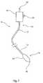
- the balloon catheterincludes a catheter 12 having a proximal end 14 and a distal end 16. At the proximal end 14, the catheter is coupled to a manipulation unit and valve assembly 18, which typically includes one or more haemostatic valves (not shown), a port 20 for feeding flushing liquid into the catheter 12, typically saline solution, and a proximal cannula 22 for use, for example, in feeding a guide wire (not shown) through the catheter 12.
- a manipulation unit and valve assembly 18typically includes one or more haemostatic valves (not shown)
- a port 20 for feeding flushing liquid into the catheter 12typically saline solution
- a proximal cannula 22for use, for example, in feeding a guide wire (not shown) through the catheter 12.
- the balloon 24may be used, for example, in an angioplasty or other vessel dilatation procedure, for valvuloplasty, for occlusion, or for any other procedure.
- the balloon 24is typically wrappable around the catheter 12, the latter extending through the balloon 24 to the tip 26 of the assembly 10.
- the balloonis also inflatable, via an inflation lumen in the catheter 12, so as to attain a deployed, inflated configuration, as shown in Figure 1 .
- the balloon 24may have a variety of shapes but typically may have a substantially cylindrical body portion bounded by conical end portions which themselves are bounded to neck portions which are fixed in fluid tight manner to the catheter 12.
- FIG. 2is cross-sectional view of a part of the balloon 30 taken along the longitudinal axis of the balloon.
- Figure 3is a view of the balloon 30 along its longitudinal axis.
- the balloon 30has a body portion 32 which is substantially cylindrical. This is bounded by first and second conical ends 34 which in turn terminate at first and second necks 36 which are typically bonded or otherwise sealed to a catheter 50.
- catheter 50extends through the balloon 30 and is provided, typically, with an inflation lumen 52 which has a port 54 in communication with the internal chamber 38 of the balloon 30.
- Inflation lumen 52is used to inflate and deflate the balloon 30 for deployment purposes, in a manner well known in the art.
- the balloon 30is formed, of an inner layer 40 and an outer layer 42.
- the inner and outer layers 40,42have a substantially even thickness, although it is not excluded that they may have a non-uniform thickness.
- the outer layeris thick compared to, for example, a layer of adhesive, which may alternatively be used to bind an additional component to a balloon.
- the end cones 34 and/or the necks 36may have a thickness which varies, for example as a result of the method of manufacture of the balloon.
- the outer layer 42is integral with or otherwise bonded to the inner layer 40.
- the structure of layers 40, 42is such that when the balloon 30 is inflated, by means of inflation fluid fed through the lumen 54 of the catheter 50, the balloon 30 will unwrap from the catheter 50 and expand to its inflated condition shown in Figures 2 and 3 .
- the strengthening element 44is fully embedded in the outer layer 42 of the balloon 30 such that it lies within the outer layer.
- the strengthening elementmay be embedded further into the balloon such that it lies substantially between the inner 40 and outer 42 layers of the balloon 30.
- the strengthening elementmay be partially embedded in the outer layer such that at least part of the strengthening element protrudes from the second layer.
- the strengthening elementis a strengthening sleeve such as a braided or otherwise constructed mesh made from filamentary material.
- the filamentary materialmay be, for example, a metal wire.
- the strengthening elementis a strengthening layer.
- the inner layer 40 of the balloon 30can be made of a variety of materials including, for example, polyamide (e.g. Nylon), polyether block amide (e.g. Pebax), polyethylene, polyurethane, silicone, polyethylene terephthalate (PET) or other suitable material.
- the heat set temperature for Nylon and Pebaxmay be approximately 140-145 degrees centigrade.
- the outer layer 42 of the ballooncould be made of similar materials or a different material than that of the inner layer 40, all being of a formulation having a lower softening or melting temperature than the material of the first balloon layer.
- the outer layer 42is preferably made of a functionalised polyolefin resin or a polyurethane resin.
- either or both layers 40, 42can be made from a plurality of compounds.
- the outer layer 42may be formed from a polyolefin base material modified with functional chemical groups to make it more hydrophilic.
- suitable materials for the outer layerinclude an anhydride-modified ethylene elastomer based adhesive resin (such as Admer® SF755A) or an anhydride-modified linear low density polyethylene (such as Plexar® PX3236).
- the physical characteristics of the balloonis substantially determined by the inner layer.
- the outer layerhas no significant influence on such characteristics of the balloon. Therefore, the thickness of the inner layer is preferably equal to the thickness of a single layer balloon with the desired physical characteristics of the medical balloon.
- the inner layerprovides a support for the outer layer at all stages of manufacture, allowing the properties and characteristics of the outer layer to change without compromising the physical characteristics of the balloon.
- the ballooncould be non-compliant, semi-compliant or compliant in dependence upon the medical application.
- the compliance of the inner layer 40can be determined by a number of factors, including the material used, the nature of that material, the thicknesses of the layer and so on. These are all parameters which a person skilled in the art will be able to ascertain on the basis of common general knowledge.
- the strengthening element 44is just one example of an additional component or feature which may be incorporated into a medical balloon for use in medical procedures.
- a radiopaque element 74is embedded so as to lie substantially between the inner 70 and outer 72 layers of the balloon 71.
- the balloon 71includes inner and outer layers 70,72 of the type disclosed herein.
- the radiopaque elementis made from radiopaque material such as, for example, palladium, silver and other radiopaque materials known to the skilled person.
- the radiopaque elementis a radiopaque layer. In other embodiments the radiopaque element maybe a radiopaque marker-block.
- the radiopaque elementmay be embedded within the outer layer so that it is surrounded by the outer layer, or partially embedded in the outer layer such that it extends from the outer layer.
- FIG. 5shows a view of another example of a medical balloon 81 along its longitudinal axis.
- the balloon 81comprises a plurality of scoring elements 84 which extend longitudinally along the length of the balloon.
- the scoring elementswhich may be thin wires or fibres 84, are stiffer than the balloon wall so that they can score into the wall of the vessel in which the balloon is inflated.
- the scoring elementsmay comprise a plastic polymer material, or a metal or metal alloy, such as Kevlar for example.
- the scoring elements 84are embedded in the outer layer 82 of the balloon 81 and protrude above the circular perimeter of the balloon so as to be able to interact with the wall of the lumen in which the balloon 81 is placed. In the embodiment shown in Figure 5 the scoring elements 84 extend along the main body part of the balloon only, not along the narrower end cone and neck portions of the balloon.
- the balloon 80has inner and outer layers 80,82 of the characteristics taught herein.
- the additional components described with reference to the Figurescould be used individually or in combination with one another.
- the componentsmay be arranged about any particular portion of the balloon, or about the entire balloon.
- the structure of the balloon and its method of manufacture, described below,allows for the provision of medical balloons having a variety of additional components such that the specific characteristics of the balloon can be tailored for a particular medical application.
- FIG. 6there is shown in schematic form an embodiment of assembly 100 for use in the manufacture of medical balloon and balloon catheters of the types disclosed herein.
- the assembly 100includes a mould 102, a pumping unit 104 for pumping inflation fluid through a conduit 106 into the mould 102 and specifically into a raw tubing from which the medical balloon is formed as described in further detail below.
- the pumping unit 104may be provided with a heater 108 for heating the pumping fluid to various temperatures.
- Figure 7there is shown a cross-sectional view of an embodiment of the raw tubing 131 for a medical balloon positioned inside a mould 112 shaped to produce a medical balloon having a strengthening element 134 incorporated into it.
- Figure 8shows a cross-sectional view along X-X of the raw tubing and mould of Figure 7 .
- the mould 112has an internal wall 114 with a substantially cylindrical surface 116 bounded by tapering sections 118 which in practice will form the end cones 34 of the balloon.
- a strengthening sleeveis located in the mould between the raw tubing and the mould but not attached to either the mould or the tubing before the balloon is heated and expanded to incorporate the strengthening sleeve.
- the mould 112is longitudinally divided in at least two portions forming half a mould each.
- the structure of the mould 112is not, however, relevant to the disclosure herein in that the mould 112 could have sections divided in other ways, for example transversally rather than longitudinally, in order to gain access to the inside of the mould for the purposes of removing a balloon formed therewithin.
- longitudinal groovesmay be provided within the substantially cylindrical portion 116 of the mould in order to provide a support for the strengthening wires or scoring elements.
- the longitudinal groovesmay extend longitudinally along inside surface of the cylindrical portion 116. The grooves can support the additional components before they are incorporated into the outer layer of the balloon in the balloon forming process.
- the additional componentsmay be lightly attached to the mould or the tubing so as to support them in a desired position relative to the raw tubing 131.
- the raw tubing 131of the type used in making a medical balloon of any of the types disclosed herein, is located within the mould 112.
- the raw tubing 131is formed, for example by co-extrusion, of two layers 130 and 132.
- the inner layer 130forms the inner layer 40, 70, 80 of the balloon, whereas the outer layer 132 forms the outer layer 42, 72, 82 of the balloon. These layers are thus made of the same material as the eventual layers of the balloon.
- the raw tubing 131is fed into the mould 112, typically in the direction of the arrow 122 shown in Figure 7 so as to extend into and through the mould 112. Once so fed, the raw tubing 131 is suitably clamped into the mould and closed off at its extreme end. The fixing is such as to seal the end in fluid tight manner. This arrangement is known in the art and will thus be immediately evident to the skilled person.
- the tubing 131which is typically a very long or continuous length of tubing, is cut to an appropriate length and then coupled to the conduit 106, in a known manner.
- the conduit 106may form a balloon catheter 12, in which case the raw tubing 131 would be fixed over the catheter after having been cut to size with its two ends sealed to the catheter 12 at locations which would form the necks 36 of the balloon.
- the mould 112is heated to a preheat temperature, such as, for example, 100 degrees centigrade. Additionally, fluid pressure, typically also heated, is fed by means of the pump (104 shown in Figure 6 ) into the raw tubing 131.
- the heat applied to the raw tubingcauses the inner layer 130 of the raw tubing to soften slightly and allows it to stretch when the pressure of the inflation fluid pushes against it, such that the raw tubing can expand within the chamber of the mould 112.
- the raw tubing 131is expanded towards the internal wall 114 of the mould 112, and the outer layer 132 is eventually pressed against these walls and against the strengthening element 134 by continuing inflation pressure.
- the temperature of the mould 112is increased so as to heat the inner layer 130 to its optimum heat set temperature.
- the outer layer 132 of the balloonis softened more than the inner layer such that it is able to flow.
- the outer layer 132is able to flow, when the outer layer 132 is pushed against any additional component present in the mould the outer layer 132 is displaced around said additional component and the additional component is forced into the outer layer 132.
- the inner layer 130remains more solid and is not able to flow, the inner layer is not displaced around the additional component; the additional component does not to penetrate the inner layer.
- the outer layer of the tubingmay be displaced around the additional component to varying extents, for example, only slightly so as to partially embed the additional component in the surface of the outer layer, or more substantially so as to fully embed the additional element in the outer layer.
- the extentmay depend on the thickness of the outer layer, the thickness of the additional element, and the temperature to which the tubing is heated in the preheat step.
- the additional componentis a strengthening element
- Both the inner and outer layers 130,132 of the balloonsare heat-set at the heat set temperature of the inner layer.
- the inner layeris set so as to fix the bonds between the molecules in the expanded tube configuration and to substantially prevent shrinkage on cooling.
- the outer layeris also set so as to set the bonds between the molecules in the expanded tube configuration.
- Figure 9is a graph depicting the shrinkage of the inner 200 and outer 190 layers and the burst strength of the inner 220 and outer 210 layers of balloon material as they vary with temperature.
- the graphshows that as temperature is increased to a materials heat set temperature (Heat set A and plot 220 for the inner layer and Heat set B and plot 210 for the outer layer) the burst strength of that material rises, only to fall again on heating to above the heat set temperature.
- the graphalso shows that as the temperature is increased above the heat set temperature the shrinkage of the balloon is dramatically reduced (when cooled after heating).
- the graphalso shows that once the material is heated to its heat set temperature, heating over that heat set temperature does not continue to reduce shrinkage on cooling. There is a preferred point therefore for each material at the heat set temperature where shrinkage is minimised and burst strength is maximised.
- heating the outer layer to the heat set temperature of the inner layerwhich heats the outer layer to a temperature above its own heat set temperature, results in a decrease in burst strength of the outer layer. This is possibly caused by breakage of the polymer chains of the material.
- the mould 112is cooled or allowed to cool. On cooling the additional components are fixed into the outer layer of the balloon and thus incorporated into the balloon.
- the mould 112is preferably cooled to substantially ambient temperature, and the balloon then removed from the mould. Typically, this can be achieved by deflating the balloon so as to facilitate its retraction form the mould surfaces.
- the provision of two layers to the balloon integral with one anotherenables the reflow, molten or softened outer layer to be supported by the more solid inner layer upon heating and inflation of the balloon.
- the outer layercan be changed structurally so as to incorporate additional components or features into the balloon, whilst the inner layer maintains the physical characteristics required by the balloon such as burst strength and compliance. In such a way additional components may be incorporated into a balloon in an easy and effective way without compromising the physical characteristics of the balloon.
- the inner layeracts to provide support to the outer layer, both during the manufacture of the balloon and also during subsequent deployment of the balloon in a medical procedure.
- the second layer of the ballooncomprises a soft layer.
- softit is meant that the layer may deform around an element or device, such as a stent, pressed into it.
- the second layerremains relatively soft after manufacture of the balloon such that an element or device may be partially embedded into the soft layer after manufacture of the balloon.
- a stentis crimped into the soft layer, partially embedding the stent into the soft layer and thus attaching the stent to the balloon.
- the soft layeris thicker than the first layer in order to provide sufficient thickness for the stent to partially embed.
- the soft layermay have a thickness substantially equal to the thickness of the stent strut.
- any compatible materialscould be used for the two layers (for example, two hydrophobic layers or two hydrophilic layers), as long at the material for the inner layer has a higher melting temperature than that of the outer layer.
- the preferred embodimentshave only two balloon layers, the layers having been preferably co-extruded to form the raw tubing used to form the balloon, or otherwise bonded to one another so as to be integral with one-another.
- Other embodimentscontemplate more than two layers, for example, three or more, with the proviso that the outer layer of the balloon remains supported by an internal layer which does not melt or flow so as to incorporate additional components at the processing temperatures.
- the raw tubingmay comprise two separate layers, each layer being a separate raw tube. The two separate raw tubes may be provided one inside the other, closely adjacent to one another.
Landscapes
- Health & Medical Sciences (AREA)
- Life Sciences & Earth Sciences (AREA)
- Engineering & Computer Science (AREA)
- Public Health (AREA)
- Veterinary Medicine (AREA)
- Animal Behavior & Ethology (AREA)
- General Health & Medical Sciences (AREA)
- Heart & Thoracic Surgery (AREA)
- Manufacturing & Machinery (AREA)
- Epidemiology (AREA)
- Anesthesiology (AREA)
- Pulmonology (AREA)
- Hematology (AREA)
- Biomedical Technology (AREA)
- Child & Adolescent Psychology (AREA)
- Biophysics (AREA)
- Mechanical Engineering (AREA)
- Chemical Kinetics & Catalysis (AREA)
- Chemical & Material Sciences (AREA)
- Vascular Medicine (AREA)
- Physics & Mathematics (AREA)
- Optics & Photonics (AREA)
- Materials For Medical Uses (AREA)
- Media Introduction/Drainage Providing Device (AREA)
Description
- The present invention relates to a method of making a medical balloon, to a medical balloon and to a balloon catheter including such a balloon.
- Medical balloons are used for a variety of medical procedures including angioplasty, scoring, vessel dilatation, valvuloplasty, occlusion and for many other applications. In many such applications, it is desirable to provide additional components to tailor the balloon to improve its function in each of the various specific uses. One common procedure involving the use of a balloon catheter relates to angioplasty dilation of coronary or other arteries suffering from stenosis (that is, a narrowing of the arterial lumen which restricts blood flow). In angioplasty techniques the proper dilation of stenosed regions that are hardened and/or have become calcified can be difficult with a standard medical balloon. Therefore it is known to fix cutting elements, such as blades, onto the surface of the balloon in order to cut away at plaque and other build-up on the interior walls of a lumen. The blades may be fixed to the balloon with a layer of adhesive in a process can be fiddly and time consuming.
- Often the manufacture of medical balloons is a complex and time consuming task, particularly having regard to the importance for reliability of the device.
- Medical balloons are disclosed in a number of earlier publications including, for example, in
US 2010/0036314 ,US 6,143,416 ,US 6,786,889 ,US2010/130926 ,EP-A-0745395 ,US2003/055447 ,US 2009/0,299,450 ,US 5,620,649 ,US 7,828,766 andUS 2010/0,262,218 . - The present invention seeks to provide an improved method of making a medical balloon and an improved medical balloon and balloon catheter.
- According to an aspect of the present invention there is provided a method of forming a medical balloon as specified in claim 1.
- The method may include the step of incorporating a feature or component into the second layer. For example the method may comprise the step of applying texture to the second layer, in particular to an outer surface of the second layer. The method may include the steps of providing adjacent the second layer at least one component and pressing the at least one component into the second layer such that the at least one component becomes at least partially embedded in the second layer. The at least one component may become fully embedded in the second layer.
- Preferably the method provides a single stage process for forming a medical balloon, in particular for incorporating a feature or component into a medical balloon. The process can be faster and simpler than known methods for producing medical balloons.
- The raw tubing may be a single tube having first and second layers integral with one another. The raw tubing may comprise two separate raw tubing layers. The two separate raw tubing layers may be held closely adjacent to one another. The second layer may be an outer layer of the raw tubing. The first layer may be an inner layer of the raw tubing.
- The preheating step may heat the raw tubing to around 100 degrees centigrade.
- The first heat set temperature may be in the region of 130 to 150 degrees centigrade. The first heat set temperature may be in the region of 140 to 150 degrees centigrade. The first heat set temperature may be the optimum heat set temperature of the first material.
- According to another aspect of the present invention, there is provided a medical balloon for a balloon catheter as specified in
claim 10. The inner layer may act as a support for the outer layer. The inner layer may support the outer layer at all times, even during manufacture of the balloon from raw tubing. By provision of the supporting inner layer the balloon can be adapted to include an additional feature or component in the outer layer without compromising the physical characteristics of the balloon, such as its strength or integrity. Even if the outer layer loses strength or integrity, for example during manufacture, the balloon can maintain the characteristics required to perform its function by virtue of the presence of the inner layer. - The inner layer may be made from polyamide, polyether block amide, polyurethane, polyethylene, polyethylene terephthalate (PET) or silicone. The polyamide may be Nylon. The polyether block amide may be Pebax. The outer layer may be made from the same material as the inner layer, treated to have a lower softening or melting temperature than that of the inner layer. The outer layer may be made from any material having a lower melting temperature than the inner layer. For example the outer layer may be made from a resin, such as a functionalised polyolefin resin or a polyurethane resin. Examples of suitable materials for the outer layer include an anhydride-modified ethylene elastomer based adhesive resin (such as Admer® SF755A), an anhydride-modified linear low density polyethylene (such as Plexar® PX3236 or a polyolefin modified with functional chemical groups to render it more hydrophilic. The outer layer may be an amorphous polymer. In an embodiment the outer layer is non-elastomeric. In an embodiment, both layers are thermoplastic elastomers. The inner layer may be a polyurethane that may be unmodified. The outer layer may be a polyolefin, which may be modified with hydroxyl groups or modified with anhydride groups.
- The outer layer may be softened or melted at or above a preheat or first processing temperature of the inner layer. By preheat or first processing temperature it is meant a temperature at which the inner layer can be stretched. The preheat or first processing temperature may be the temperature to which the balloon is heated to in a preheat step. The preheat or first processing temperature may be, for example, 100 degrees centigrade. The melting temperature of the outer layer may be under 100°C, under 120°C or under 140°C. The preferred melting temperature of the outer layer may be in the range of 115 to 125 degrees centigrade. In an embodiment, the melting temperature of the inner layer may be in the range of about 165 to about 205 degrees centigrade.
- When a material is heated to its heat set temperature whilst it is stretched, for example by inflation of the balloon, the material becomes fixed such that when inflation pressure is removed from the balloon the material maintains its size and form, rather than returning to its pre-inflated size and form. It is believed that at the heat set temperature the molecules of the material are substantially locked into their orientations such that on cooling the molecules do not return to any orientation they may have had before heat setting.
- A balloon may be stretched and heated below the heat set temperature and on cooling may return, or at least partially return, to its pre-stretched and preheated form. Heating a material to its heat set temperature may reduce, in particular minimise, shrinkage of the balloon on cooling after heating. Heating a balloon material to its heat set temperature may also increase the burst strength of the balloon. Heating a balloon material to a temperature above its heat set temperature may result in loss of burst strength compared to the burst strength of the balloon after heating only to its heat set temperature and then cooling. Heating a material to a temperature higher than its heat set temperature may overheat the material. By over-heating the balloon material it may lose at least some of its strength, possibly as a result in breakage of the polymer chains of the material. For example the outer layer may lose its burst strength by heating it to the heat-set temperature of the inner layer.
- The inner layer may have a heat set temperature between around 130 to 150 degrees centigrade, 140 to 150 degrees centigrade, or 145 to 150 degrees centigrade. The heat set temperature of the outer layer may be less than about 140 degrees centigrade. In embodiments it may be less than about 100 degrees centigrade. The outer layer may have a heat set temperature of around 55 to 70 degrees centigrade. The outer layer may have a heat set temperature of around 50 to 60 degrees centigrade. The outer layer may have a heat set temperature which is at least 80, 70, 60, 50, 40 or 30 degrees centigrade less than the heat set temperature of the first layer. The outer layer may have a heat set temperature which is at least 20 degrees centigrade less than the heat set temperature of the inner layer. The outer layer may have a heat set temperature which is at least 10 degrees centigrade less than the heat set temperature of the inner layer. The outer layer may have a heat set temperature which is no more than around 80% of the heat set temperature of the inner layer.
- Where the heat set temperature is a temperature range, the inner layer may have an optimum heat set temperature within the heat set temperature range. Heating the balloon to the optimum heat set temperature of the inner layer may result in a balloon for which shrinkage is minimised and burst strength is maximised.
- Due to the relative hardness of the two layers, the inner layer may provide a harder support for the outer layer.
- The inner layer may have a thickness in the range from 0.01 millimetres to 0.05 millimetres. The inner layer may have a thickness in the range from 0.02 millimetres to 0.04 millimetres. The outer layer may have a thickness in the range from 0.003 millimetres to 0.02 millimetres. The outer layer may have a thickness which is no more than 20% of a thickness of the inner layer. The outer layer may have a thickness which is no more than 40% of a thickness of the inner layer.
- In embodiments the thickness of the outer layer may be equal to the thickness of the inner layer. For example the outer layer may have a thickness in the range from 0.01 millimetres to 0.05 millimetres. In other embodiments the thickness of the outer layer may be greater than the thickness of the inner layer. For example the outer layer may have a thickness of up to 0.2mm. A thicker outer layer may be provided so as to enable elements to be at least partially embedded into the outer layer.
- The thickness of the inner layer of the balloon may be chosen so as to provide the desired physical characteristics of the balloon. The physical characteristics of the balloon, such as burst strength, compliance and shape may be substantially determined by the inner layer. The outer layer may have no significant influence on such characteristics of the balloon. The inner layer of the balloon may have a thickness equal to that of a single layer balloon exhibiting the desired physical characteristics of the balloon.
- Preferably the burst strength of the inner layer is higher than the burst strength of outer layer.
- The medical balloon may include at least one feature or component in the outer layer. The outer layer preferably has sufficient thickness such that an additional component may be securely embedded in the outer layer, or sufficient thickness such that an additional feature may be provided in the outer layer. An additional component may be partially or completely embedded in the outer layer. The outer layer may be relatively thick, for example it may be thicker than adhesive layers which have been used to bind additional components to balloons in existing products. As such additional components may be incorporated into a balloon of a balloon catheter more securely and more easily.
- The medical balloon may include at least one other layer integral with the inner and outer layers, the outer layer being an outer layer of the balloon.
- The medical balloon may include at least one component at least partially embedded in the outer layer. The component may be or may include a strengthening sleeve, a woven material, a scoring element, a burst resist wire, a radiopaque marker, a cutting element, a high friction element, or a texturizing element. A texturizing element may for example be roughening particles which, when incorporated into the second layer, provide a roughened surface of the second layer. The additional component may tailor the features of the balloon, for example to improve the balloon's performance for a specific use. The additional component may be integral with the outer layer of the balloon for example by being embedded in or incorporated into the outer layer. The additional component may protrude beyond the surface of the outer layer of the balloon, for example to provide a scoring surface.
- The outer layer may comprise a soft layer. By soft it is meant that the layer may deform around an element or device, such as a stent, pressed into it. The second layer may remain relatively soft after manufacture of the balloon such that an element or device may be partially embedded into the soft layer after manufacture of the balloon. For example, a stent may be crimped into the soft layer in order to attach it to the balloon. In this case the stent may be partially embedded in the soft layer. Where the outer layer is a soft layer the outer layer may be thicker than the inner layer.
- The outer layer may comprise a high friction layer. For example the outer layer may comprise a material which gives the surface of the outer layer high friction.
- The medical balloon may include at least one feature in the outer layer. For example the outer layer may be textured, such as roughened, or the outer layer may be a high friction layer.
- Embodiments of the present invention are described below, by way of example only, with reference to the accompanying drawings, in which:
Figure 1 is a schematic diagram of a balloon catheter;Figure 2 is a cross-sectional sectional view of an embodiment of the medical balloon taught herein;Figure 3 is a cross-sectional view along Y-Y of the medical balloon ofFigure 2 ;Figure 4 is a cross-sectional sectional view of another embodiment of the medical balloon;Figure 5 is a cross-sectional view of yet another embodiment of the medical balloon;Figure 6 , is a schematic view of an embodiment of assembly for use in the manufacture of medical balloon and balloon catheters of the types disclosed herein;Figure 7 is a cross-sectional view of an embodiment of the raw tubing for a medical balloon positioned inside a mould, for manufacturing a medical balloon as taught herein;Figure 8 is a cross-sectional view along X-X of the raw tubing and mould ofFigure 7 ; andFigure 9 is a graph depicting the shrinkage and burst strength of the inner and outer layers of balloon material as they vary with temperature.- It is to be understood that the drawings are schematic only and are not intended to be representative of dimensions or proportions of the various elements shown therein. In some instances, dimensions, sizes and proportions have been modified in order to assist in the visualisation of various features of the elements shown, that is for the purpose of explanation only. The person skilled in the art will be aware of the appropriate dimensions and proportions having regard to common knowledge in the art.
- Referring to
Figure 1 , there is shown in schematic form the principal components of aballoon catheter assembly 10, which components are generally known in the art. The balloon catheter includes acatheter 12 having aproximal end 14 and adistal end 16. At theproximal end 14, the catheter is coupled to a manipulation unit andvalve assembly 18, which typically includes one or more haemostatic valves (not shown), aport 20 for feeding flushing liquid into thecatheter 12, typically saline solution, and aproximal cannula 22 for use, for example, in feeding a guide wire (not shown) through thecatheter 12. - At the
distal end 16 of theballoon catheter 20, there is provided amedical balloon 24. Theballoon 24 may be used, for example, in an angioplasty or other vessel dilatation procedure, for valvuloplasty, for occlusion, or for any other procedure. Theballoon 24 is typically wrappable around thecatheter 12, the latter extending through theballoon 24 to thetip 26 of theassembly 10. The balloon is also inflatable, via an inflation lumen in thecatheter 12, so as to attain a deployed, inflated configuration, as shown inFigure 1 . Theballoon 24 may have a variety of shapes but typically may have a substantially cylindrical body portion bounded by conical end portions which themselves are bounded to neck portions which are fixed in fluid tight manner to thecatheter 12. - Referring now to
Figures 2 and 3 , there is shown a first embodiment ofmedical balloon 30 according to the teachings herein. Theballoon 30 has a strengtheningelement 44 for strengthening the balloon.Figure 2 is cross-sectional view of a part of theballoon 30 taken along the longitudinal axis of the balloon.Figure 3 , on the other hand, is a view of theballoon 30 along its longitudinal axis. Theballoon 30 has abody portion 32 which is substantially cylindrical. This is bounded by first and second conical ends 34 which in turn terminate at first andsecond necks 36 which are typically bonded or otherwise sealed to acatheter 50. It will be apparent, in particular fromFigure 2 , thatcatheter 50 extends through theballoon 30 and is provided, typically, with aninflation lumen 52 which has aport 54 in communication with theinternal chamber 38 of theballoon 30.Inflation lumen 52 is used to inflate and deflate theballoon 30 for deployment purposes, in a manner well known in the art. - As can be seen in
Figure 2 , theballoon 30 is formed, of aninner layer 40 and anouter layer 42. Typically, the inner andouter layers end cones 34 and/or thenecks 36 may have a thickness which varies, for example as a result of the method of manufacture of the balloon. - The
outer layer 42 is integral with or otherwise bonded to theinner layer 40. The structure oflayers balloon 30 is inflated, by means of inflation fluid fed through thelumen 54 of thecatheter 50, theballoon 30 will unwrap from thecatheter 50 and expand to its inflated condition shown inFigures 2 and 3 . - The strengthening
element 44 is fully embedded in theouter layer 42 of theballoon 30 such that it lies within the outer layer. The strengthening element may be embedded further into the balloon such that it lies substantially between the inner 40 and outer 42 layers of theballoon 30. In another embodiment the strengthening element may be partially embedded in the outer layer such that at least part of the strengthening element protrudes from the second layer. - In a preferred embodiment the strengthening element is a strengthening sleeve such as a braided or otherwise constructed mesh made from filamentary material. The filamentary material may be, for example, a metal wire. In one embodiment the strengthening element is a strengthening layer.
- The
inner layer 40 of theballoon 30 can be made of a variety of materials including, for example, polyamide (e.g. Nylon), polyether block amide (e.g. Pebax), polyethylene, polyurethane, silicone, polyethylene terephthalate (PET) or other suitable material. The heat set temperature for Nylon and Pebax may be approximately 140-145 degrees centigrade. Theouter layer 42 of the balloon could be made of similar materials or a different material than that of theinner layer 40, all being of a formulation having a lower softening or melting temperature than the material of the first balloon layer. Theouter layer 42 is preferably made of a functionalised polyolefin resin or a polyurethane resin. Of course, either or bothlayers outer layer 42 may be formed from a polyolefin base material modified with functional chemical groups to make it more hydrophilic. Examples of suitable materials for the outer layer include an anhydride-modified ethylene elastomer based adhesive resin (such as Admer® SF755A) or an anhydride-modified linear low density polyethylene (such as Plexar® PX3236). - In a preferred embodiment the physical characteristics of the balloon, such as burst strength, compliance and shape is substantially determined by the inner layer. Preferably the outer layer has no significant influence on such characteristics of the balloon. Therefore, the thickness of the inner layer is preferably equal to the thickness of a single layer balloon with the desired physical characteristics of the medical balloon. The inner layer provides a support for the outer layer at all stages of manufacture, allowing the properties and characteristics of the outer layer to change without compromising the physical characteristics of the balloon.
- The balloon could be non-compliant, semi-compliant or compliant in dependence upon the medical application. The compliance of the
inner layer 40 can be determined by a number of factors, including the material used, the nature of that material, the thicknesses of the layer and so on. These are all parameters which a person skilled in the art will be able to ascertain on the basis of common general knowledge. - It is to be appreciated that the strengthening
element 44 is just one example of an additional component or feature which may be incorporated into a medical balloon for use in medical procedures. The teachings herein, particularly in connection with the method of manufacture of the balloon described below, allow for a large variety of different additional components to be incorporated into a medical balloon. - Some examples are given in
Figures 4 and 5 , to which reference is now made. All of these Figures show cross-sectional views of different examples of medical balloon. - In
Figure 4 , aradiopaque element 74 is embedded so as to lie substantially between the inner 70 and outer 72 layers of theballoon 71. As with the previously described embodiments, theballoon 71 includes inner andouter layers 70,72 of the type disclosed herein. The radiopaque element is made from radiopaque material such as, for example, palladium, silver and other radiopaque materials known to the skilled person. - In a preferred embodiment the radiopaque element is a radiopaque layer. In other embodiments the radiopaque element maybe a radiopaque marker-block.
- As described previously with reference to other additional components incorporated into the balloon, in other embodiments the radiopaque element may be embedded within the outer layer so that it is surrounded by the outer layer, or partially embedded in the outer layer such that it extends from the outer layer.
Figure 5 shows a view of another example of amedical balloon 81 along its longitudinal axis. Theballoon 81 comprises a plurality of scoringelements 84 which extend longitudinally along the length of the balloon. The scoring elements, which may be thin wires orfibres 84, are stiffer than the balloon wall so that they can score into the wall of the vessel in which the balloon is inflated. The scoring elements may comprise a plastic polymer material, or a metal or metal alloy, such as Kevlar for example. The scoringelements 84 are embedded in theouter layer 82 of theballoon 81 and protrude above the circular perimeter of the balloon so as to be able to interact with the wall of the lumen in which theballoon 81 is placed. In the embodiment shown inFigure 5 thescoring elements 84 extend along the main body part of the balloon only, not along the narrower end cone and neck portions of the balloon. Theballoon 80 has inner andouter layers - The additional components described with reference to the Figures could be used individually or in combination with one another. The components may be arranged about any particular portion of the balloon, or about the entire balloon.
- The structure of the balloon and its method of manufacture, described below, allows for the provision of medical balloons having a variety of additional components such that the specific characteristics of the balloon can be tailored for a particular medical application.
- There follows a description of a preferred embodiment of manufacturing a balloon having characteristics of the type disclosed herein.
- Referring now to
Figure 6 , there is shown in schematic form an embodiment ofassembly 100 for use in the manufacture of medical balloon and balloon catheters of the types disclosed herein. - The
assembly 100 includes amould 102, apumping unit 104 for pumping inflation fluid through aconduit 106 into themould 102 and specifically into a raw tubing from which the medical balloon is formed as described in further detail below. Thepumping unit 104 may be provided with aheater 108 for heating the pumping fluid to various temperatures. There may be provided aseparate heating unit 110 for heating themould 102 during the process of fabrication of a medical balloon. - In
Figure 7 there is shown a cross-sectional view of an embodiment of theraw tubing 131 for a medical balloon positioned inside amould 112 shaped to produce a medical balloon having a strengtheningelement 134 incorporated into it.Figure 8 shows a cross-sectional view along X-X of the raw tubing and mould ofFigure 7 . Themould 112 has aninternal wall 114 with a substantiallycylindrical surface 116 bounded by taperingsections 118 which in practice will form theend cones 34 of the balloon. - A strengthening sleeve is located in the mould between the raw tubing and the mould but not attached to either the mould or the tubing before the balloon is heated and expanded to incorporate the strengthening sleeve.
- In the example of
Figure 7 , themould 112 is longitudinally divided in at least two portions forming half a mould each. The structure of themould 112 is not, however, relevant to the disclosure herein in that themould 112 could have sections divided in other ways, for example transversally rather than longitudinally, in order to gain access to the inside of the mould for the purposes of removing a balloon formed therewithin. - Where the additional component is a strengthening wire, or a scoring element, for example, longitudinal grooves (not shown) may be provided within the substantially
cylindrical portion 116 of the mould in order to provide a support for the strengthening wires or scoring elements. The longitudinal grooves may extend longitudinally along inside surface of thecylindrical portion 116. The grooves can support the additional components before they are incorporated into the outer layer of the balloon in the balloon forming process. In another embodiment the additional components may be lightly attached to the mould or the tubing so as to support them in a desired position relative to theraw tubing 131. - The
raw tubing 131, of the type used in making a medical balloon of any of the types disclosed herein, is located within themould 112. Theraw tubing 131 is formed, for example by co-extrusion, of twolayers inner layer 130 forms theinner layer outer layer 132 forms theouter layer - In practice, the
raw tubing 131 is fed into themould 112, typically in the direction of the arrow 122 shown inFigure 7 so as to extend into and through themould 112. Once so fed, theraw tubing 131 is suitably clamped into the mould and closed off at its extreme end. The fixing is such as to seal the end in fluid tight manner. This arrangement is known in the art and will thus be immediately evident to the skilled person. - The
tubing 131, which is typically a very long or continuous length of tubing, is cut to an appropriate length and then coupled to theconduit 106, in a known manner. In practice, theconduit 106 may form aballoon catheter 12, in which case theraw tubing 131 would be fixed over the catheter after having been cut to size with its two ends sealed to thecatheter 12 at locations which would form thenecks 36 of the balloon. - The
mould 112 is heated to a preheat temperature, such as, for example, 100 degrees centigrade. Additionally, fluid pressure, typically also heated, is fed by means of the pump (104 shown inFigure 6 ) into theraw tubing 131. The heat applied to the raw tubing causes theinner layer 130 of the raw tubing to soften slightly and allows it to stretch when the pressure of the inflation fluid pushes against it, such that the raw tubing can expand within the chamber of themould 112. Theraw tubing 131 is expanded towards theinternal wall 114 of themould 112, and theouter layer 132 is eventually pressed against these walls and against the strengtheningelement 134 by continuing inflation pressure. - Once the
tubing 131 has been preheated and expanded to push against thewall 114 of themould 112 the temperature of themould 112 is increased so as to heat theinner layer 130 to its optimum heat set temperature. - At or above the preheat temperature the
outer layer 132 of the balloon is softened more than the inner layer such that it is able to flow. As theouter layer 132 is able to flow, when theouter layer 132 is pushed against any additional component present in the mould theouter layer 132 is displaced around said additional component and the additional component is forced into theouter layer 132. As theinner layer 130 remains more solid and is not able to flow, the inner layer is not displaced around the additional component; the additional component does not to penetrate the inner layer. - The outer layer of the tubing may be displaced around the additional component to varying extents, for example, only slightly so as to partially embed the additional component in the surface of the outer layer, or more substantially so as to fully embed the additional element in the outer layer. The extent may depend on the thickness of the outer layer, the thickness of the additional element, and the temperature to which the tubing is heated in the preheat step. In the embodiment shown in
Figures 7 and8 , where the additional component is a strengthening element, it is desired that the strengthening element be completely embedded in the outer layer of the balloon. - Both the inner and outer layers 130,132 of the balloons are heat-set at the heat set temperature of the inner layer. The inner layer is set so as to fix the bonds between the molecules in the expanded tube configuration and to substantially prevent shrinkage on cooling. The outer layer is also set so as to set the bonds between the molecules in the expanded tube configuration.
Figure 9 is a graph depicting the shrinkage of the inner 200 and outer 190 layers and the burst strength of the inner 220 and outer 210 layers of balloon material as they vary with temperature.- The graph shows that as temperature is increased to a materials heat set temperature (Heat set A and
plot 220 for the inner layer and Heat set B andplot 210 for the outer layer) the burst strength of that material rises, only to fall again on heating to above the heat set temperature. The graph also shows that as the temperature is increased above the heat set temperature the shrinkage of the balloon is dramatically reduced (when cooled after heating). - The graph also shows that once the material is heated to its heat set temperature, heating over that heat set temperature does not continue to reduce shrinkage on cooling. There is a preferred point therefore for each material at the heat set temperature where shrinkage is minimised and burst strength is maximised.
- As can been seen from the graph, heating the outer layer to the heat set temperature of the inner layer, which heats the outer layer to a temperature above its own heat set temperature, results in a decrease in burst strength of the outer layer. This is possibly caused by breakage of the polymer chains of the material.
- However, this does not compromise the strength or burst strength of the balloon as the inner layer maintains its strength and provides the physical characteristics of the balloon.
- Once the balloon has been heat set, the
mould 112 is cooled or allowed to cool. On cooling the additional components are fixed into the outer layer of the balloon and thus incorporated into the balloon. Themould 112 is preferably cooled to substantially ambient temperature, and the balloon then removed from the mould. Typically, this can be achieved by deflating the balloon so as to facilitate its retraction form the mould surfaces. - The provision of two layers to the balloon integral with one another enables the reflow, molten or softened outer layer to be supported by the more solid inner layer upon heating and inflation of the balloon. As such the outer layer can be changed structurally so as to incorporate additional components or features into the balloon, whilst the inner layer maintains the physical characteristics required by the balloon such as burst strength and compliance. In such a way additional components may be incorporated into a balloon in an easy and effective way without compromising the physical characteristics of the balloon. The inner layer acts to provide support to the outer layer, both during the manufacture of the balloon and also during subsequent deployment of the balloon in a medical procedure.
- In some embodiments the second layer of the balloon comprises a soft layer. By soft it is meant that the layer may deform around an element or device, such as a stent, pressed into it. The second layer remains relatively soft after manufacture of the balloon such that an element or device may be partially embedded into the soft layer after manufacture of the balloon. In one embodiment, a stent is crimped into the soft layer, partially embedding the stent into the soft layer and thus attaching the stent to the balloon. The soft layer is thicker than the first layer in order to provide sufficient thickness for the stent to partially embed. For example, the soft layer may have a thickness substantially equal to the thickness of the stent strut.
- The skilled person would appreciate that modifications could be made to the above-described embodiments. Any compatible materials could be used for the two layers (for example, two hydrophobic layers or two hydrophilic layers), as long at the material for the inner layer has a higher melting temperature than that of the outer layer. Furthermore, it would be possible to combine a hydrophilic layer with a hydrophobic layer by chemically linking the layers or including a middle "tie" layer with intermediate properties.
- The preferred embodiments have only two balloon layers, the layers having been preferably co-extruded to form the raw tubing used to form the balloon, or otherwise bonded to one another so as to be integral with one-another. Other embodiments contemplate more than two layers, for example, three or more, with the proviso that the outer layer of the balloon remains supported by an internal layer which does not melt or flow so as to incorporate additional components at the processing temperatures. In some embodiments the raw tubing may comprise two separate layers, each layer being a separate raw tube. The two separate raw tubes may be provided one inside the other, closely adjacent to one another.
Claims (15)
- A method of forming a medical balloon (30) provided with a first layer (40) made from a first material and a second layer (42) made from a second material, said first and second layers being in overlying relationship with one another and integral with one another, wherein the first material has a softening or melting temperature which is higher than a softening or melting temperature of the second material; the method including the steps of:providing first and second layers of raw tubing made of said first and second materials respectively;locating said raw tubing (131) in a mould (112); preheating the raw tubing to a preheat temperature and inflating the raw tubing so as to cause it to expand;heating the raw tubing to a first heat set temperature being the heat set temperature of the first layer (40), wherein at said preheat temperature and/or first heat set temperature the second layer is molten;setting the inflated raw tubing to form the medical balloon (30); and cooling the set balloon.
- A method according to claim 1, wherein the method provides a single stage process for forming a medical balloon.
- A method according to claim 1 or 2, wherein the second layer is the outer layer of the raw tubing.
- A method according to claim 1, 2 or 3, wherein said first heat set temperature is greater than a temperature which may cause degradation of the material of the second layer and/or wherein the first heat set temperature is the optimum heat set temperature of the first material.
- A method according to any of claims 1 to 4, including the step of incorporating a feature or component into the second layer, or a medical balloon according to any of claims 5 to 9, including at least one feature or component incorporated into the outer layer.
- A method according any of claims 1 to 5, including the step of applying texture to the second layer, or a medical balloon according to any of claims 6 to 14, the outer layer having a textured outer surface.
- A method according any of claims 1 to 6, including the steps of providing adjacent the second layer at least one component and pressing the at least one component into the second layer such that the at least one component becomes at least partially embedded in the second layer, or a medical balloon according to any of claims 5 to 11, including at least one component at least partially embedded in the outer layer, optionally wherein the at least one component becomes fully embedded in the second layer.
- A method according any of claims 1 to 7, wherein the first heat set temperature is in the region of 130 to 150 degrees centigrade, or a medical balloon according to any of claims 6 to 18 wherein the inner layer has a heat set temperature between around 130 to 150 degrees centigrade; and/or wherein the second material has a melting temperature of 115 to 125 degrees centigrade.
- A method according any of claims 1 to 8, wherein the first material is a polyurethane; and/or wherein the second material is a polyolefin modified with hydrophilic groups, optionally wherein the second material is a polyolefin modified with hydroxyl groups or modified with anhydride groups.
- A medical balloon for a balloon catheter, which balloon has at least an inner layer made from a first material and an outer layer made from a second material, wherein the outer layer is softer than the inner layer, said inner and outer layers being in overlying relationship with one another and being integral with one another; wherein the inner layer has a softening or melting temperature which is higher than a softening or melting temperature of the outer layer; wherein the inner layer has a first heat set temperature above which the inner layer is heat set and wherein the melting temperature of the second material is below the heat set temperature of the first material.
- A medical balloon according to claim 10, wherein the outer layer has a heat set temperature which is at least 10 degrees centigrade less than the heat set temperature of the inner layer, optionally wherein the outer layer has a heat set temperature which is at least 20 degrees centigrade less than the heat set temperature of the first layer; and/or wherein the outer layer has a heat set temperature which is no more than around 80% of the heat set temperature of the first layer.
- A medical balloon according to claim 10 or 11, wherein the inner layer has a higher burst strength than the outer layer.
- A medical balloon according to claim 10, 11 or 12, wherein the inner layer is made from a material selected from the group consisting of polyamide, polyether block amide, polyurethane, polyethylene, polyethylene terephthalate (PET) and silicone; and/or wherein the outer layer is made from the same material as the inner layer, treated to have a lower softening or melting temperature than that of the inner layer.
- A medical balloon according to any of claims 10 to 13, including at least one other layer integral with the inner and outer layers, the outer layer being an outer layer of the balloon.
- A medical balloon according to claim 10, wherein the component is or includes a strengthening sleeve, a woven material, a scoring element, a burst resist wire, a radiopaque marker, a cutting element, a high friction element, or a texturizing element.
Applications Claiming Priority (3)
| Application Number | Priority Date | Filing Date | Title |
|---|---|---|---|
| GB1205369.0AGB2501243B (en) | 2012-03-27 | 2012-03-27 | Method of making a medical balloon |
| US13/794,972US9327102B2 (en) | 2012-03-27 | 2013-03-12 | Method of making a medical balloon |
| PCT/IB2013/052470WO2013144885A1 (en) | 2012-03-27 | 2013-03-27 | Method of Making a Medical Balloon |
Publications (2)
| Publication Number | Publication Date |
|---|---|
| EP2830855A1 EP2830855A1 (en) | 2015-02-04 |
| EP2830855B1true EP2830855B1 (en) | 2017-11-22 |
Family
ID=46087196
Family Applications (1)
| Application Number | Title | Priority Date | Filing Date |
|---|---|---|---|
| EP13722095.0AActiveEP2830855B1 (en) | 2012-03-27 | 2013-03-27 | Method of making a medical balloon and medical balloon |
Country Status (4)
| Country | Link |
|---|---|
| US (3) | US9327102B2 (en) |
| EP (1) | EP2830855B1 (en) |
| GB (1) | GB2501243B (en) |
| WO (1) | WO2013144885A1 (en) |
Families Citing this family (17)
| Publication number | Priority date | Publication date | Assignee | Title |
|---|---|---|---|---|
| GB2501243B (en)* | 2012-03-27 | 2014-06-18 | Cook Medical Technologies Llc | Method of making a medical balloon |
| US9833597B2 (en) | 2014-05-12 | 2017-12-05 | Cook Medical Technologies Llc | Textile balloon catheters |
| GB2526104B (en) | 2014-05-13 | 2017-01-11 | Cook Medical Technologies Llc | Medical balloon assembly and method of making a medical balloon |
| EP3189870A4 (en)* | 2014-09-04 | 2018-04-18 | Terumo Kabushiki Kaisha | Catheter |
| JP6307388B2 (en)* | 2014-09-04 | 2018-04-04 | テルモ株式会社 | Catheter and manufacturing method thereof |
| WO2016035741A1 (en)* | 2014-09-04 | 2016-03-10 | テルモ株式会社 | Catheter and method for manufacturing same |
| CN106573130B (en)* | 2014-09-04 | 2020-01-24 | 泰尔茂株式会社 | Catheter tube |
| JP6307387B2 (en)* | 2014-09-04 | 2018-04-04 | テルモ株式会社 | catheter |
| JP6307389B2 (en)* | 2014-09-04 | 2018-04-04 | テルモ株式会社 | catheter |
| US10668257B2 (en) | 2014-10-16 | 2020-06-02 | W. L. Gore & Associates, Inc. | Blow molded composite devices and methods |
| CN107666872B (en) | 2015-02-26 | 2021-05-18 | 舒尔默迪克斯公司 | Insertable medical device system with plaque treatment portion and method of use |
| US10182841B1 (en)* | 2015-06-16 | 2019-01-22 | C.R. Bard, Inc. | Medical balloon with enhanced focused force control |
| US9669918B1 (en) | 2015-07-28 | 2017-06-06 | X Development Llc | Sealing ducts into a balloon |
| US10029776B1 (en) | 2015-09-18 | 2018-07-24 | X Development Llc | Seals for gored balloon |
| US9908609B1 (en) | 2016-06-02 | 2018-03-06 | X Development Llc | Explosive strip for venting gas from a balloon |
| CN106512184B (en)* | 2016-12-09 | 2022-06-07 | 江苏常美医疗器械有限公司 | Quick clamping and inflating device for conduit |
| JP7380018B2 (en)* | 2019-09-27 | 2023-11-15 | ニプロ株式会社 | balloon catheter |
Family Cites Families (23)
| Publication number | Priority date | Publication date | Assignee | Title |
|---|---|---|---|---|
| US5478320A (en) | 1989-11-29 | 1995-12-26 | Cordis Corporation | Puncture resistant balloon catheter and method of manufacturing |
| AU5246696A (en)* | 1995-05-30 | 1996-12-12 | Ethicon Inc. | Single-walled balloon catheter with non-linear compliance characteristic |
| GB9612324D0 (en) | 1996-06-13 | 1996-08-14 | Lrc Products | Polyurethane articles |
| KR100548661B1 (en)* | 1997-07-07 | 2006-02-03 | 데이진 가부시키가이샤 | Biaxially Oriented Polyester Film For Magnetic Recording Media |
| US6358227B1 (en)* | 1997-09-10 | 2002-03-19 | Scimed Life Systems, Inc. | Dilatation catheter balloon made from pen based homopolymer or random copolymer |
| US6786889B1 (en) | 1999-03-31 | 2004-09-07 | Scimed Life Systems, Inc | Textured and/or marked balloon for stent delivery |
| US6258099B1 (en) | 1999-03-31 | 2001-07-10 | Scimed Life Systems, Inc. | Stent security balloon/balloon catheter |
| US6863678B2 (en)* | 2001-09-19 | 2005-03-08 | Advanced Cardiovascular Systems, Inc. | Catheter with a multilayered shaft section having a polyimide layer |
| US20060030835A1 (en)* | 2004-06-29 | 2006-02-09 | Sherman Darren R | Catheter shaft tubes and methods of making |
| US7309324B2 (en)* | 2004-10-15 | 2007-12-18 | Futuremed Interventional, Inc. | Non-compliant medical balloon having an integral woven fabric layer |
| US7828766B2 (en) | 2005-12-20 | 2010-11-09 | Advanced Cardiovascular Systems, Inc. | Non-compliant multilayered balloon for a catheter |
| US8518103B2 (en)* | 2007-06-04 | 2013-08-27 | Boston Scientific Scimed, Inc. | Bifurcated delivery system and method |
| US20090029450A1 (en) | 2007-07-25 | 2009-01-29 | Nikon Corporation | Incubator |
| EP2095795A1 (en) | 2007-12-21 | 2009-09-02 | Abbott Laboratories Vascular Enterprises Limited | Double layered balloons in medical devices |
| US8771332B2 (en) | 2008-05-29 | 2014-07-08 | Boston Scientific Scimed, Inc. | Multi-layer balloon design for use in combination with catheter assemblies, and methods of making the same |
| US9067045B2 (en) | 2008-07-25 | 2015-06-30 | Cook Medical Technologies Llc | Balloon catheter and method for making same |
| US8052638B2 (en)* | 2008-11-26 | 2011-11-08 | Abbott Cardiovascular Systems, Inc. | Robust multi-layer balloon |
| US8444608B2 (en)* | 2008-11-26 | 2013-05-21 | Abbott Cardivascular Systems, Inc. | Robust catheter tubing |
| US20100158193A1 (en)* | 2008-12-22 | 2010-06-24 | Bates Mark C | Interventional Devices Formed Using Compositions Including Metal-Coated Nanotubes Dispersed In Polymers, And Methods Of Making And Using Same |
| US8864786B2 (en) | 2009-04-09 | 2014-10-21 | Medtronic Vascular, Inc. | Dual-layer medical balloon and process of making |
| US8703260B2 (en)* | 2010-09-14 | 2014-04-22 | Abbott Cardiovascular Systems Inc. | Catheter balloon and method for forming same |
| GB2501243B (en)* | 2012-03-27 | 2014-06-18 | Cook Medical Technologies Llc | Method of making a medical balloon |
| EP2968681A1 (en)* | 2013-03-15 | 2016-01-20 | Abbott Cardiovascular Systems Inc. | Catheter shaft and method of forming same |
- 2012
- 2012-03-27GBGB1205369.0Apatent/GB2501243B/enactiveActive
- 2013
- 2013-03-12USUS13/794,972patent/US9327102B2/enactiveActive
- 2013-03-27EPEP13722095.0Apatent/EP2830855B1/enactiveActive
- 2013-03-27WOPCT/IB2013/052470patent/WO2013144885A1/enactiveApplication Filing
- 2016
- 2016-03-22USUS15/077,533patent/US10086179B2/enactiveActive
- 2018
- 2018-08-29USUS16/115,897patent/US20180369547A1/ennot_activeAbandoned
Also Published As
| Publication number | Publication date |
|---|---|
| US9327102B2 (en) | 2016-05-03 |
| US10086179B2 (en) | 2018-10-02 |
| GB2501243B (en) | 2014-06-18 |
| US20180369547A1 (en) | 2018-12-27 |
| US20160199623A1 (en) | 2016-07-14 |
| US20130261547A1 (en) | 2013-10-03 |
| EP2830855A1 (en) | 2015-02-04 |
| GB201205369D0 (en) | 2012-05-09 |
| GB2501243A (en) | 2013-10-23 |
| WO2013144885A1 (en) | 2013-10-03 |
Similar Documents
| Publication | Publication Date | Title |
|---|---|---|
| EP2830855B1 (en) | Method of making a medical balloon and medical balloon | |
| EP2644211B1 (en) | Medical balloon with particles therein | |
| EP2056915B1 (en) | Refoldable balloon and method of making the same | |
| US8192675B2 (en) | Cutting balloon with connector and dilation element | |
| AU2017295675B2 (en) | High-pressure dilation catheter balloon | |
| EP2990069A1 (en) | Shaped or textured medical balloon | |
| US5681522A (en) | Method and apparatus for annealing angioplasty balloons to improve re-wrappability thereof | |
| EP2644171B1 (en) | Method of manufacture of a medical balloon with textured or roughened outer layer | |
| US9901717B2 (en) | Medical balloon with incorporated fibers | |
| JP2009528152A (en) | New balloon catheter mold design | |
| US20090234282A1 (en) | Outer Catheter Shaft to Balloon Joint |
Legal Events
| Date | Code | Title | Description |
|---|---|---|---|
| PUAI | Public reference made under article 153(3) epc to a published international application that has entered the european phase | Free format text:ORIGINAL CODE: 0009012 | |
| 17P | Request for examination filed | Effective date:20140804 | |
| AK | Designated contracting states | Kind code of ref document:A1 Designated state(s):AL AT BE BG CH CY CZ DE DK EE ES FI FR GB GR HR HU IE IS IT LI LT LU LV MC MK MT NL NO PL PT RO RS SE SI SK SM TR | |
| AX | Request for extension of the european patent | Extension state:BA ME | |
| DAX | Request for extension of the european patent (deleted) | ||
| RIC1 | Information provided on ipc code assigned before grant | Ipc:B29C 49/04 20060101AFI20170426BHEP Ipc:A61L 29/04 20060101ALN20170426BHEP Ipc:A61L 29/18 20060101ALN20170426BHEP Ipc:B29C 49/22 20060101ALI20170426BHEP Ipc:B29C 49/78 20060101ALI20170426BHEP Ipc:A61L 29/06 20060101ALN20170426BHEP Ipc:A61M 25/10 20130101ALN20170426BHEP Ipc:B29L 31/00 20060101ALN20170426BHEP | |
| RIC1 | Information provided on ipc code assigned before grant | Ipc:A61L 29/06 20060101ALN20170509BHEP Ipc:B29L 31/00 20060101ALN20170509BHEP Ipc:A61M 25/10 20130101ALN20170509BHEP Ipc:A61L 29/04 20060101ALN20170509BHEP Ipc:B29C 49/04 20060101AFI20170509BHEP Ipc:B29C 49/78 20060101ALI20170509BHEP Ipc:B29C 49/22 20060101ALI20170509BHEP Ipc:A61L 29/18 20060101ALN20170509BHEP | |
| RIC1 | Information provided on ipc code assigned before grant | Ipc:B29L 31/00 20060101ALN20170516BHEP Ipc:B29C 49/04 20060101AFI20170516BHEP Ipc:A61L 29/18 20060101ALN20170516BHEP Ipc:A61L 29/06 20060101ALN20170516BHEP Ipc:B29C 49/22 20060101ALI20170516BHEP Ipc:B29C 49/78 20060101ALI20170516BHEP Ipc:A61M 25/10 20130101ALN20170516BHEP Ipc:A61L 29/04 20060101ALN20170516BHEP | |
| GRAP | Despatch of communication of intention to grant a patent | Free format text:ORIGINAL CODE: EPIDOSNIGR1 | |
| STAA | Information on the status of an ep patent application or granted ep patent | Free format text:STATUS: GRANT OF PATENT IS INTENDED | |
| RIC1 | Information provided on ipc code assigned before grant | Ipc:A61L 29/18 20060101ALN20170608BHEP Ipc:A61M 25/10 20130101ALN20170608BHEP Ipc:B29C 49/04 20060101AFI20170608BHEP Ipc:B29C 49/78 20060101ALI20170608BHEP Ipc:B29C 49/22 20060101ALI20170608BHEP Ipc:A61L 29/04 20060101ALN20170608BHEP Ipc:A61L 29/06 20060101ALN20170608BHEP Ipc:B29L 31/00 20060101ALN20170608BHEP | |
| INTG | Intention to grant announced | Effective date:20170711 | |
| RBV | Designated contracting states (corrected) | Designated state(s):AL AT BE BG CH CY CZ DE DK EE ES FI FR GR HR HU IE IS IT LI LT LU LV MC MK MT NL NO PL PT RO RS SE SI SK SM TR | |
| RIC1 | Information provided on ipc code assigned before grant | Ipc:A61L 29/18 20060101ALN20170727BHEP Ipc:A61L 29/06 20060101ALN20170727BHEP Ipc:B29C 49/22 20060101ALI20170727BHEP Ipc:B29C 49/78 20060101ALI20170727BHEP Ipc:A61L 29/04 20060101ALN20170727BHEP Ipc:B29C 49/04 20060101AFI20170727BHEP Ipc:B29L 31/00 20060101ALN20170727BHEP Ipc:A61M 25/10 20130101ALN20170727BHEP | |
| RIN1 | Information on inventor provided before grant (corrected) | Inventor name:BOEDEWADT, TUE Inventor name:AGGERHOLM, STEEN Inventor name:LYSGAARD, THOMAS | |
| GRAS | Grant fee paid | Free format text:ORIGINAL CODE: EPIDOSNIGR3 | |
| GRAA | (expected) grant | Free format text:ORIGINAL CODE: 0009210 | |
| STAA | Information on the status of an ep patent application or granted ep patent | Free format text:STATUS: THE PATENT HAS BEEN GRANTED | |
| AK | Designated contracting states | Kind code of ref document:B1 Designated state(s):AL AT BE BG CH CY CZ DE DK EE ES FI FR GR HR HU IE IS IT LI LT LU LV MC MK MT NL NO PL PT RO RS SE SI SK SM TR | |
| REG | Reference to a national code | Ref country code:CH Ref legal event code:EP | |
| REG | Reference to a national code | Ref country code:IE Ref legal event code:FG4D | |
| REG | Reference to a national code | Ref country code:AT Ref legal event code:REF Ref document number:947997 Country of ref document:AT Kind code of ref document:T Effective date:20171215 | |
| REG | Reference to a national code | Ref country code:DE Ref legal event code:R096 Ref document number:602013029751 Country of ref document:DE | |
| REG | Reference to a national code | Ref country code:NL Ref legal event code:MP Effective date:20171122 | |
| REG | Reference to a national code | Ref country code:LT Ref legal event code:MG4D | |
| REG | Reference to a national code | Ref country code:AT Ref legal event code:MK05 Ref document number:947997 Country of ref document:AT Kind code of ref document:T Effective date:20171122 | |
| PG25 | Lapsed in a contracting state [announced via postgrant information from national office to epo] | Ref country code:ES Free format text:LAPSE BECAUSE OF FAILURE TO SUBMIT A TRANSLATION OF THE DESCRIPTION OR TO PAY THE FEE WITHIN THE PRESCRIBED TIME-LIMIT Effective date:20171122 Ref country code:NO Free format text:LAPSE BECAUSE OF FAILURE TO SUBMIT A TRANSLATION OF THE DESCRIPTION OR TO PAY THE FEE WITHIN THE PRESCRIBED TIME-LIMIT Effective date:20180222 Ref country code:FI Free format text:LAPSE BECAUSE OF FAILURE TO SUBMIT A TRANSLATION OF THE DESCRIPTION OR TO PAY THE FEE WITHIN THE PRESCRIBED TIME-LIMIT Effective date:20171122 Ref country code:NL Free format text:LAPSE BECAUSE OF FAILURE TO SUBMIT A TRANSLATION OF THE DESCRIPTION OR TO PAY THE FEE WITHIN THE PRESCRIBED TIME-LIMIT Effective date:20171122 Ref country code:SE Free format text:LAPSE BECAUSE OF FAILURE TO SUBMIT A TRANSLATION OF THE DESCRIPTION OR TO PAY THE FEE WITHIN THE PRESCRIBED TIME-LIMIT Effective date:20171122 Ref country code:LT Free format text:LAPSE BECAUSE OF FAILURE TO SUBMIT A TRANSLATION OF THE DESCRIPTION OR TO PAY THE FEE WITHIN THE PRESCRIBED TIME-LIMIT Effective date:20171122 | |
| PG25 | Lapsed in a contracting state [announced via postgrant information from national office to epo] | Ref country code:AT Free format text:LAPSE BECAUSE OF FAILURE TO SUBMIT A TRANSLATION OF THE DESCRIPTION OR TO PAY THE FEE WITHIN THE PRESCRIBED TIME-LIMIT Effective date:20171122 Ref country code:HR Free format text:LAPSE BECAUSE OF FAILURE TO SUBMIT A TRANSLATION OF THE DESCRIPTION OR TO PAY THE FEE WITHIN THE PRESCRIBED TIME-LIMIT Effective date:20171122 Ref country code:RS Free format text:LAPSE BECAUSE OF FAILURE TO SUBMIT A TRANSLATION OF THE DESCRIPTION OR TO PAY THE FEE WITHIN THE PRESCRIBED TIME-LIMIT Effective date:20171122 Ref country code:BG Free format text:LAPSE BECAUSE OF FAILURE TO SUBMIT A TRANSLATION OF THE DESCRIPTION OR TO PAY THE FEE WITHIN THE PRESCRIBED TIME-LIMIT Effective date:20180222 Ref country code:LV Free format text:LAPSE BECAUSE OF FAILURE TO SUBMIT A TRANSLATION OF THE DESCRIPTION OR TO PAY THE FEE WITHIN THE PRESCRIBED TIME-LIMIT Effective date:20171122 Ref country code:GR Free format text:LAPSE BECAUSE OF FAILURE TO SUBMIT A TRANSLATION OF THE DESCRIPTION OR TO PAY THE FEE WITHIN THE PRESCRIBED TIME-LIMIT Effective date:20180223 | |
| PG25 | Lapsed in a contracting state [announced via postgrant information from national office to epo] | Ref country code:SK Free format text:LAPSE BECAUSE OF FAILURE TO SUBMIT A TRANSLATION OF THE DESCRIPTION OR TO PAY THE FEE WITHIN THE PRESCRIBED TIME-LIMIT Effective date:20171122 Ref country code:CZ Free format text:LAPSE BECAUSE OF FAILURE TO SUBMIT A TRANSLATION OF THE DESCRIPTION OR TO PAY THE FEE WITHIN THE PRESCRIBED TIME-LIMIT Effective date:20171122 Ref country code:CY Free format text:LAPSE BECAUSE OF FAILURE TO SUBMIT A TRANSLATION OF THE DESCRIPTION OR TO PAY THE FEE WITHIN THE PRESCRIBED TIME-LIMIT Effective date:20171122 Ref country code:DK Free format text:LAPSE BECAUSE OF FAILURE TO SUBMIT A TRANSLATION OF THE DESCRIPTION OR TO PAY THE FEE WITHIN THE PRESCRIBED TIME-LIMIT Effective date:20171122 Ref country code:EE Free format text:LAPSE BECAUSE OF FAILURE TO SUBMIT A TRANSLATION OF THE DESCRIPTION OR TO PAY THE FEE WITHIN THE PRESCRIBED TIME-LIMIT Effective date:20171122 | |
| REG | Reference to a national code | Ref country code:DE Ref legal event code:R097 Ref document number:602013029751 Country of ref document:DE | |
| PG25 | Lapsed in a contracting state [announced via postgrant information from national office to epo] | Ref country code:PL Free format text:LAPSE BECAUSE OF FAILURE TO SUBMIT A TRANSLATION OF THE DESCRIPTION OR TO PAY THE FEE WITHIN THE PRESCRIBED TIME-LIMIT Effective date:20171122 Ref country code:RO Free format text:LAPSE BECAUSE OF FAILURE TO SUBMIT A TRANSLATION OF THE DESCRIPTION OR TO PAY THE FEE WITHIN THE PRESCRIBED TIME-LIMIT Effective date:20171122 Ref country code:IT Free format text:LAPSE BECAUSE OF FAILURE TO SUBMIT A TRANSLATION OF THE DESCRIPTION OR TO PAY THE FEE WITHIN THE PRESCRIBED TIME-LIMIT Effective date:20171122 Ref country code:SM Free format text:LAPSE BECAUSE OF FAILURE TO SUBMIT A TRANSLATION OF THE DESCRIPTION OR TO PAY THE FEE WITHIN THE PRESCRIBED TIME-LIMIT Effective date:20171122 | |
| PLBE | No opposition filed within time limit | Free format text:ORIGINAL CODE: 0009261 | |
| STAA | Information on the status of an ep patent application or granted ep patent | Free format text:STATUS: NO OPPOSITION FILED WITHIN TIME LIMIT | |
| 26N | No opposition filed | Effective date:20180823 | |
| REG | Reference to a national code | Ref country code:CH Ref legal event code:PL | |
| PG25 | Lapsed in a contracting state [announced via postgrant information from national office to epo] | Ref country code:SI Free format text:LAPSE BECAUSE OF FAILURE TO SUBMIT A TRANSLATION OF THE DESCRIPTION OR TO PAY THE FEE WITHIN THE PRESCRIBED TIME-LIMIT Effective date:20171122 Ref country code:MC Free format text:LAPSE BECAUSE OF FAILURE TO SUBMIT A TRANSLATION OF THE DESCRIPTION OR TO PAY THE FEE WITHIN THE PRESCRIBED TIME-LIMIT Effective date:20171122 | |
| REG | Reference to a national code | Ref country code:BE Ref legal event code:MM Effective date:20180331 | |
| PG25 | Lapsed in a contracting state [announced via postgrant information from national office to epo] | Ref country code:LU Free format text:LAPSE BECAUSE OF NON-PAYMENT OF DUE FEES Effective date:20180327 | |
| PG25 | Lapsed in a contracting state [announced via postgrant information from national office to epo] | Ref country code:BE Free format text:LAPSE BECAUSE OF NON-PAYMENT OF DUE FEES Effective date:20180331 Ref country code:CH Free format text:LAPSE BECAUSE OF NON-PAYMENT OF DUE FEES Effective date:20180331 Ref country code:LI Free format text:LAPSE BECAUSE OF NON-PAYMENT OF DUE FEES Effective date:20180331 | |
| PG25 | Lapsed in a contracting state [announced via postgrant information from national office to epo] | Ref country code:FR Free format text:LAPSE BECAUSE OF NON-PAYMENT OF DUE FEES Effective date:20180331 | |
| PG25 | Lapsed in a contracting state [announced via postgrant information from national office to epo] | Ref country code:MT Free format text:LAPSE BECAUSE OF NON-PAYMENT OF DUE FEES Effective date:20180327 | |
| PG25 | Lapsed in a contracting state [announced via postgrant information from national office to epo] | Ref country code:TR Free format text:LAPSE BECAUSE OF FAILURE TO SUBMIT A TRANSLATION OF THE DESCRIPTION OR TO PAY THE FEE WITHIN THE PRESCRIBED TIME-LIMIT Effective date:20171122 | |
| PG25 | Lapsed in a contracting state [announced via postgrant information from national office to epo] | Ref country code:PT Free format text:LAPSE BECAUSE OF FAILURE TO SUBMIT A TRANSLATION OF THE DESCRIPTION OR TO PAY THE FEE WITHIN THE PRESCRIBED TIME-LIMIT Effective date:20171122 Ref country code:HU Free format text:LAPSE BECAUSE OF FAILURE TO SUBMIT A TRANSLATION OF THE DESCRIPTION OR TO PAY THE FEE WITHIN THE PRESCRIBED TIME-LIMIT; INVALID AB INITIO Effective date:20130327 | |
| PG25 | Lapsed in a contracting state [announced via postgrant information from national office to epo] | Ref country code:MK Free format text:LAPSE BECAUSE OF NON-PAYMENT OF DUE FEES Effective date:20171122 | |
| PG25 | Lapsed in a contracting state [announced via postgrant information from national office to epo] | Ref country code:AL Free format text:LAPSE BECAUSE OF FAILURE TO SUBMIT A TRANSLATION OF THE DESCRIPTION OR TO PAY THE FEE WITHIN THE PRESCRIBED TIME-LIMIT Effective date:20171122 Ref country code:IS Free format text:LAPSE BECAUSE OF FAILURE TO SUBMIT A TRANSLATION OF THE DESCRIPTION OR TO PAY THE FEE WITHIN THE PRESCRIBED TIME-LIMIT Effective date:20180322 | |
| P01 | Opt-out of the competence of the unified patent court (upc) registered | Effective date:20230602 | |
| PGFP | Annual fee paid to national office [announced via postgrant information from national office to epo] | Ref country code:DE Payment date:20250327 Year of fee payment:13 | |
| PGFP | Annual fee paid to national office [announced via postgrant information from national office to epo] | Ref country code:IE Payment date:20250318 Year of fee payment:13 |