EP2830544B1 - Tibial prosthesis systems - Google Patents
Tibial prosthesis systemsDownload PDFInfo
- Publication number
- EP2830544B1 EP2830544B1EP13716637.7AEP13716637AEP2830544B1EP 2830544 B1EP2830544 B1EP 2830544B1EP 13716637 AEP13716637 AEP 13716637AEP 2830544 B1EP2830544 B1EP 2830544B1
- Authority
- EP
- European Patent Office
- Prior art keywords
- component
- shim
- sensors
- bearing
- anterior
- Prior art date
- Legal status (The legal status is an assumption and is not a legal conclusion. Google has not performed a legal analysis and makes no representation as to the accuracy of the status listed.)
- Active
Links
Images


Classifications
- A—HUMAN NECESSITIES
- A61—MEDICAL OR VETERINARY SCIENCE; HYGIENE
- A61F—FILTERS IMPLANTABLE INTO BLOOD VESSELS; PROSTHESES; DEVICES PROVIDING PATENCY TO, OR PREVENTING COLLAPSING OF, TUBULAR STRUCTURES OF THE BODY, e.g. STENTS; ORTHOPAEDIC, NURSING OR CONTRACEPTIVE DEVICES; FOMENTATION; TREATMENT OR PROTECTION OF EYES OR EARS; BANDAGES, DRESSINGS OR ABSORBENT PADS; FIRST-AID KITS
- A61F2/00—Filters implantable into blood vessels; Prostheses, i.e. artificial substitutes or replacements for parts of the body; Appliances for connecting them with the body; Devices providing patency to, or preventing collapsing of, tubular structures of the body, e.g. stents
- A61F2/02—Prostheses implantable into the body
- A61F2/30—Joints
- A61F2/46—Special tools for implanting artificial joints
- A61F2/4684—Trial or dummy prostheses
- A—HUMAN NECESSITIES
- A61—MEDICAL OR VETERINARY SCIENCE; HYGIENE
- A61B—DIAGNOSIS; SURGERY; IDENTIFICATION
- A61B5/00—Measuring for diagnostic purposes; Identification of persons
- A61B5/103—Measuring devices for testing the shape, pattern, colour, size or movement of the body or parts thereof, for diagnostic purposes
- A61B5/1036—Measuring load distribution, e.g. podologic studies
- A—HUMAN NECESSITIES
- A61—MEDICAL OR VETERINARY SCIENCE; HYGIENE
- A61F—FILTERS IMPLANTABLE INTO BLOOD VESSELS; PROSTHESES; DEVICES PROVIDING PATENCY TO, OR PREVENTING COLLAPSING OF, TUBULAR STRUCTURES OF THE BODY, e.g. STENTS; ORTHOPAEDIC, NURSING OR CONTRACEPTIVE DEVICES; FOMENTATION; TREATMENT OR PROTECTION OF EYES OR EARS; BANDAGES, DRESSINGS OR ABSORBENT PADS; FIRST-AID KITS
- A61F2/00—Filters implantable into blood vessels; Prostheses, i.e. artificial substitutes or replacements for parts of the body; Appliances for connecting them with the body; Devices providing patency to, or preventing collapsing of, tubular structures of the body, e.g. stents
- A61F2/02—Prostheses implantable into the body
- A61F2/30—Joints
- A61F2/38—Joints for elbows or knees
- A61F2/389—Tibial components
- A—HUMAN NECESSITIES
- A61—MEDICAL OR VETERINARY SCIENCE; HYGIENE
- A61F—FILTERS IMPLANTABLE INTO BLOOD VESSELS; PROSTHESES; DEVICES PROVIDING PATENCY TO, OR PREVENTING COLLAPSING OF, TUBULAR STRUCTURES OF THE BODY, e.g. STENTS; ORTHOPAEDIC, NURSING OR CONTRACEPTIVE DEVICES; FOMENTATION; TREATMENT OR PROTECTION OF EYES OR EARS; BANDAGES, DRESSINGS OR ABSORBENT PADS; FIRST-AID KITS
- A61F2/00—Filters implantable into blood vessels; Prostheses, i.e. artificial substitutes or replacements for parts of the body; Appliances for connecting them with the body; Devices providing patency to, or preventing collapsing of, tubular structures of the body, e.g. stents
- A61F2/02—Prostheses implantable into the body
- A61F2/30—Joints
- A61F2/46—Special tools for implanting artificial joints
- A61F2/4657—Measuring instruments used for implanting artificial joints
- A—HUMAN NECESSITIES
- A61—MEDICAL OR VETERINARY SCIENCE; HYGIENE
- A61B—DIAGNOSIS; SURGERY; IDENTIFICATION
- A61B17/00—Surgical instruments, devices or methods
- A61B17/02—Surgical instruments, devices or methods for holding wounds open, e.g. retractors; Tractors
- A61B17/025—Joint distractors
- A61B2017/0268—Joint distractors for the knee
- A—HUMAN NECESSITIES
- A61—MEDICAL OR VETERINARY SCIENCE; HYGIENE
- A61B—DIAGNOSIS; SURGERY; IDENTIFICATION
- A61B90/00—Instruments, implements or accessories specially adapted for surgery or diagnosis and not covered by any of the groups A61B1/00 - A61B50/00, e.g. for luxation treatment or for protecting wound edges
- A61B90/06—Measuring instruments not otherwise provided for
- A61B2090/061—Measuring instruments not otherwise provided for for measuring dimensions, e.g. length
- A—HUMAN NECESSITIES
- A61—MEDICAL OR VETERINARY SCIENCE; HYGIENE
- A61F—FILTERS IMPLANTABLE INTO BLOOD VESSELS; PROSTHESES; DEVICES PROVIDING PATENCY TO, OR PREVENTING COLLAPSING OF, TUBULAR STRUCTURES OF THE BODY, e.g. STENTS; ORTHOPAEDIC, NURSING OR CONTRACEPTIVE DEVICES; FOMENTATION; TREATMENT OR PROTECTION OF EYES OR EARS; BANDAGES, DRESSINGS OR ABSORBENT PADS; FIRST-AID KITS
- A61F2/00—Filters implantable into blood vessels; Prostheses, i.e. artificial substitutes or replacements for parts of the body; Appliances for connecting them with the body; Devices providing patency to, or preventing collapsing of, tubular structures of the body, e.g. stents
- A61F2/02—Prostheses implantable into the body
- A61F2/30—Joints
- A61F2/46—Special tools for implanting artificial joints
- A61F2/4657—Measuring instruments used for implanting artificial joints
- A61F2002/4658—Measuring instruments used for implanting artificial joints for measuring dimensions, e.g. length
- A61F2002/4661—Measuring instruments used for implanting artificial joints for measuring dimensions, e.g. length for measuring thickness
- A—HUMAN NECESSITIES
- A61—MEDICAL OR VETERINARY SCIENCE; HYGIENE
- A61F—FILTERS IMPLANTABLE INTO BLOOD VESSELS; PROSTHESES; DEVICES PROVIDING PATENCY TO, OR PREVENTING COLLAPSING OF, TUBULAR STRUCTURES OF THE BODY, e.g. STENTS; ORTHOPAEDIC, NURSING OR CONTRACEPTIVE DEVICES; FOMENTATION; TREATMENT OR PROTECTION OF EYES OR EARS; BANDAGES, DRESSINGS OR ABSORBENT PADS; FIRST-AID KITS
- A61F2/00—Filters implantable into blood vessels; Prostheses, i.e. artificial substitutes or replacements for parts of the body; Appliances for connecting them with the body; Devices providing patency to, or preventing collapsing of, tubular structures of the body, e.g. stents
- A61F2/02—Prostheses implantable into the body
- A61F2/30—Joints
- A61F2/46—Special tools for implanting artificial joints
- A61F2/4657—Measuring instruments used for implanting artificial joints
- A61F2002/4666—Measuring instruments used for implanting artificial joints for measuring force, pressure or mechanical tension
Definitions
- Provisional knee prosthesis systemsincluding a plurality of provisional components, can be positioned on a distal end of a femur or a proximal end of a tibia to allow a surgeon to test and appropriately fit a permanent knee prosthesis system within a patient.
- the surgeoncan remove and replace a provisional component having a first uniform thickness with a provisional component having a second uniform thickness to arrive at an appropriate configuration of the permanent knee prosthesis system.
- provisional tibial prosthesis systems, kits, and methodsincluding one or more provisional tibial components that can collectively be used to replicate permanent (or final) tibial components or mimic bone cuts believed to be necessary during a surgical procedure. It is believed that the provisional tibial components can also be designed for, or find use as, permanent tibial components. Thus, while this disclosure relates to provisional uses of the present tibial prosthesis systems, kits, and methods, it should be appreciated that such subject matter can also find use in permanent applications.
- the tibial prosthesis systems, kits, and methods disclosed hereincan assist in determining a proper bone cut angle to be made (e.g., to a tibia or a femur) or a size, shape, or other configuration of a permanent tibial prosthesis system that is designed to replace all or a portion of a knee joint.
- the present inventorsrecognize, among other things, that existing provisional systems, kits, and methods fail to provide a surgeon with insight of knee joint kinematics if an angled bone cut (e.g., a bone cut that is not parallel to a joint line of the knee) is made to a proximal end of the tibia or a distal end of the femur.
- an angled bone cute.g., a bone cut that is not parallel to a joint line of the knee
- existing provisional systems, kits, and methodsrequire the stacking of a high number of provisional components to arrive at an appropriate configuration of the permanent tibial prosthesis system or fail to provide sensed force or pressure data providing a real-time indication of provisional knee joint balance.
- the inventionis defined in claim 1.
- the present shim componentswhich can include one or both of a medial edge having a different height than a lateral edge or an anterior edge having a different height than a posterior edge, advantageously provide a surgeon with knee joint kinematic insight regarding an angled bone cut before the cut is made and can reduce the number of provisional components needed for permanent system sizing.
- the present shim componentscan provide the surgeon with the ability to appropriately configure the tibia, the femur, and/or the permanent tibial prosthesis system to counterbalance a deficiency (e.g., varus, valgus, anterior/posterior, or posterior/anterior sloping) of the knee joint before making certain angled bone cuts and using a reduced number of provisional components.
- a deficiencye.g., varus, valgus, anterior/posterior, or posterior/anterior sloping
- a tibial prosthesis systemcan include a provisional bearing component, a bearing support component, such as a base or plate component, and the provisional shim component.
- the shim componentcan be inserted between an inferior surface of the bearing component and a superior surface of the bearing support component. The insertion of the shim component provides spacing adjustment between the bearing and bearing support components.
- a sensorcan be coupled to or integrated with the bearing, bearing support, or shim components for real-time knee joint balance testing.
- the present inventorsrecognize that it can be desirable to provide surgeons with knee joint kinematic insight before certain bone cuts are made (e.g., to a tibia or a femur) and with the ability to quickly create a configuration appropriate for a permanent tibial prosthesis system using provisional components.
- the present tibial prosthesis systems, kits, and methodscan include a provisional bearing component, a bearing support component, such as a base component or a plate component, and a provisional shim component.
- the shim componentcan include one or both of a medial edge having a different height than a lateral edge or an anterior edge having a different height than a posterior edge and can be inserted between the bearing component and the bearing support component.
- the differing height profile of the shim componentcan provide a surgeon with knee joint kinematic insight regarding an angled bone cut before the cut is made and can allow for sizing of an appropriate permanent prosthesis component configuration using a reduced number of provisional components.
- a sensorcan be coupled to or integrated with the bearing, bearing support, or shim components for real-time knee joint balance testing.
- FIGS. 1 and 2illustrate several features of knee joint structures and orientations.
- a frontal view of a lower limb 102including a femur 104 and a tibia 106, is shown to illustrate various lower limb axes.
- the femur 104has an anatomic axis 108 that coincides generally with its intramedullary canal.
- the femur 104also has a mechanical axis 110, or load axis, running from the center of a femoral head 112 to the center of a knee joint 114.
- the angle 116 extending between these two axesvaries among the patient population, but is generally on the order of between 5-7 degrees, inclusive.
- the tibia 106also has an anatomic axis coinciding generally with its intramedullary canal.
- the mechanical axis 118 of the tibia 106runs from the center of the knee joint 114 to the center of an ankle region 120 and is generally collinear with its anatomic axis.
- a joint line 122about which the knee joint 114 flexes, is approximately parallel to a line through medial and lateral femoral condyles 124 and to a tibial plateau 126. Although illustrated as perpendicular in FIG. 1 , the joint line 122 can extend at a varus or valgus angle relative to the mechanical axes 110 and 118 of the femur 104 and tibia 106, respectively.
- portions of a distal end of the femur 104 or a proximal end of the tibia 106are resected to be parallel or approximately parallel to the joint line 122, and thus perpendicular to the mechanical axes 110 and 118, as indicated at 128 and 130, respectively.
- FIG. 2illustrates a closer view of the knee joint 114 and its coordinate system, in which a medial/lateral axis 202 corresponds approximately to the joint line 122 ( FIG. 1 ), a proximal/distal axis 204 corresponds approximately to the mechanical axes 110 and 118 ( FIG. 1 ), and an anterior/posterior axis 206 is approximately normal to the other two axes. Position along each of these axes can be depicted by arrows, which can represent the medial/lateral 208, anterior/posterior 210, and proximal/distal 212 positioning of inserted prosthesis components. Rotation about each of these axes can also be depicted by arrows.
- Rotation about the proximal/distal axis 204can correspond anatomically to external rotation of a femoral component, while rotation about the anterior/posterior axis 206 and medial/lateral axis 202 can correspond to extension plane slope and varus/valgus angle of a component, respectively.
- a varus/valgus angle 214, extension plane angle 216, external rotation 218, or joint extension gapcan be affected.
- a position of the distal femoral cut 128( FIG. 1 ) can affect the location of the joint line 122, the extension gap, the varus/valgus angle 214, or the extension plane angle 216.
- FIG. 3illustrates a partially resected knee joint 314 structure, including a proximal tibial cut 130, and a provisional tibial prosthesis system 340.
- the provisional tibial prosthesis system 340can include a bearing component 342, a base component 344, a plate component 350, and a shim component 346 insertable between an inferior surface 348 of the bearing component 342 and a superior surface 352 of the base component 344.
- the shim component 346can include one or both of a medial edge having a different height than a lateral edge or an anterior edge having a different height than a posterior edge and can be used as a height varying spacer block between the bearing component 342 and the base component 344.
- the spacing of the bearing component 342 from the base component 344is adjustable to allow for representation of a variety of different sized angled bone cuts that can be made to a femur 104 or a tibia 106 or permanent tibial prosthesis systems.
- the shim component 346can be inserted between the inferior surface 348 of the bearing component 342 and the superior surface 352 of the base component 344 using a shim handling instrument 354.
- the shim handling instrument 354can include a release means 356 to disengage the shim component 346 after its insertion between the bearing 342 and base 344 components.
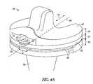
- FIGS. 4A and 4Brespectively illustrate assembled and component views of a provisional tibial prosthesis system 340.
- the provisional tibial prosthesis system 340or components thereof, can be used to mimic geometry of one or both of an angle bone cut to be made or a permanent tibial prosthesis system.
- the assembled tibial prosthesis system 340 of FIG. 4Aillustrates a bearing component 342, a shim component 346, a base component 344, and a plate component 350.
- a stem component 358can be attached to the plate component 350 and used to secure the plate component 350 to a resected tibia 106 ( FIG. 3 ).
- Each component of the provisional tibial prosthesis system 340includes an associated height.
- a shim component height 347can be combined with a bearing component height 343 and a base component height 345, for example, to represent a desired height of a permanent tibial prosthesis system.
- a plurality of different or varying sized shims 346can be slidably inserted between the bearing component 342 and a bearing support component, such as the base component 344, in an anterior/posterior 210 direction.
- the different or varying sized shims 346can be inserted and removed without removing the bearing component 342 or the bearing support component from within a knee joint 314 ( FIG. 3 ).
- the shim handling instrument 354can be used to engage one or more handling alignment voids of a shim component 346 to assist in inserting and removing the shim component 346 between the bearing component 342 and the bearing support component 344.
- the one or more handling alignment voids of the shim component 346can be consistent over the broad range of different sized shim components for universal compatibility with the shim handling instrument 354.
- Each component of the provisional tibial prosthesis system 340can include a structure defined by various surfaces, voids, or cavities.
- the bearing component 342can include an inferior surface 348, an opposing superior surface 460, and a peripheral wall 462 extending from the inferior surface 348 to the superior surface 460.
- the bearing component 342can further include an anterior side 464, a posterior side 466, a lateral side 468, and a medial side 470.
- the superior surface 460can be configured to articulate with natural or prosthetic condyles of a distal femur and can include a bearing lateral articular surface portion and a bearing medial articular surface portion, with a central tibial eminence 472 disposed between the articular surface portions.
- the inferior surface 348can include a bearing cavity and one or more bearing nub cavities.
- the bearing cavitycan extend from the inferior surface 348 toward the superior surface 460 and can be sized and shaped to accept a projection of the base component 344.
- the bearing nub cavitiescan extend on opposing sides of the bearing cavity and can each be sized and shaped to receive a nub located on the projection of the base component 344.
- a posterior cruciate ligament (PCL) cutout 474can be disposed at the posterior side 466 between the articular surfaces.
- the PCL cutout 474can be sized and positioned to correspond with a PCL of the knee joint 314.
- the bearing component 342is illustrated as a cruciate retaining bearing component, although it is contemplated that other tibial bearing components can be used. Bearing components that cooperate to form a posterior stabilized prosthesis, as shown in the example of FIG. 4A , or a knee prosthesis having an intermediate level of constraint between a posterior stabilized and cruciate retaining prosthesis are within the scope of the present disclosure.
- the bearing component 342can also be made available in a variety of shapes and sizes to accommodate a variety of patient knee joints.
- the base component 344can include an inferior surface 476, an opposing superior surface 352, and a peripheral wall 480 extending from the inferior surface 476 to the superior surface 352.
- the base component 344can further include an anterior side 481, a posterior side 482, a lateral side 484, and a medial side 486.
- a projection 488, including one or more nubs 490,can extend from the superior surface 352.
- the projection 488 and nubs 490can be configured to be received within, and couple to, the bearing and bearing nub cavities of the bearing component 342.
- the base component 344can include one or more of a W-shaped notch 492 at the posterior side 482, an undercut portion to mate with a raised perimeter of the plate component 350, a medial side groove, and a lateral side groove.
- the bearing component 342 and the base component 344can be coupled to or engaged with each other.
- the bearing component 342can be positioned atop of the base component 344 and the projection 488, including the one or more nubs 490, of the base component 344 can be positioned within the bearing and bearing nub cavities of the bearing component 342.
- the base component 344can be secured to the bearing component 342 in a medial/lateral direction 208 ( FIG. 2 ) when the projection 488 is received with the bearing cavity and can be secured in an anterior/posterior direction 210 ( FIG. 2 ) when the one or more nubs 490 are received with respective nub cavities.
- the walls of the bearing cavitycan provide a physical barrier to inhibit significant relative movement between the base component 344 and the bearing component 342 in the medial/lateral direction 208.
- the walls of the bearing nub cavitiescan provide a physical barrier to inhibit significant relative movement between the base component 344 and the bearing component 342 in the anterior/posterior direction 210.
- the base component 344can be secured to the base plate 350, such that the base component 344 is located between the bearing component 342 and the base plate 350.
- the shim component 346can include an inferior surface 461, an opposing superior surface 463, and a peripheral wall 465 extending from the inferior surface 461 to the superior surface 463.
- the peripheral wall 465can define an exterior profile of the shim component 346.
- the exterior profile of the shim component 346can substantially match an exterior profile of the base component 344 or the plate component 350.
- the shim component 346can further include an anterior side 467, a posterior side 469, a lateral side 471, and a medial side 473.
- the superior surface 463can include one or more rails 475 and one or more handling alignment voids 477.
- the one or more rails 475can be configured to slidably engage one or more slots on the inferior surface 348 of the bearing component 342.
- the rails 475can extend from the anterior side 467 toward the posterior side 469, such in an orientation parallel to the anterior/posterior direction 210.
- the rails 475can include lead-in edges 479 to facilitate alignment and engagement with the slots of the bearing component 342.
- the rail 475/slot engagement between the shim component 346 and the bearing component 342can inhibit lift-off the bearing component 342 from the shim component 346.
- the one or more handling alignment voids 477can be configured to engage with an interface of a shim handling instrument, such as is shown in FIG. 6A .
- a set of different sized shim components 346can be provided in a kit to allow for varying levels of adjustment of the provisional tibial prosthesis system 340 and insight into knee joint kinematics if certain bone cuts are made to a tibia 106 ( FIG. 1 ) or a femur 104 ( FIG. 1 ). Particularly, the distance between the bearing component 342 and the base component 344 can be increased or decreased by inserting and removing different sized shim components 346. At least one of the shim components 346 can include one or both of a medial edge having a different height than a lateral edge or an anterior edge having a different height than a posterior edge.
- the medial edge height and the lateral edge heightcan be sized such that the inferior surface 461 of the shim component 346 includes a medial to lateral angle of between +3 degrees and -3 degrees, inclusive.
- the anterior edge height and the posterior edge heightcan be sized such that the inferior surface 461 of the shim component 346 includes an anterior to posterior angle of between +3 degrees and -3 degrees, inclusive.
- Two or more shim components 346 from the setcan, in an example, be stacked to achieve desirable knee joint kinematics. It is believed that the set of different sized shim components 346 can include any desired number of shims having a constant or differing height.
- FIG. 5illustrates a method 500 of using a provisional tibial prosthesis system to determine a proper angle of a bone cut to be made, if any, and an appropriate size (e.g., height) for a permanent tibial prosthesis system in a knee joint.
- a surgeon or other caregiverselects a particular size of the provisional tibial prosthesis system believed to be suitable for a patient.
- the provisional tibial prosthesis systemcan include a bearing member, a bearing support component, comprising one or both of a base component or a plate component, and a shim component.
- the plate componentcan include an inferior surface configured to contact a resected portion of a tibia and an opposing superior surface.
- the base componentcan include a base component height and be attachable to the plate component.
- the bearing componentcan include a bearing component height
- the shim componentcan include a shim component height.
- the shim componentcan be configured to be slidably received between the bearing component and the bearing support component in an anterior/posterior direction.
- a proximal end portion of the patient's tibiais resected to be parallel or approximately parallel to a joint line of a knee.
- the tibiacan be resected using standard surgical techniques to provide a substantially flat surface for receipt of the inferior, bone contacting surface of the plate component.
- the plate componentcan be implanted and secured to the resected tibia, at 506.
- one or more of the selected bearing, shim, and base componentscan be positioned atop the plate component.
- the selected bearing and base componentscan initially be positioned atop the plate component, and subsequently, the selected shim component can be inserted between the bearing and base components in the anterior/posterior direction.
- the inserted shim componentcan include one or both of a medial edge having a different height than a lateral edge or an anterior edge having a different height than a posterior edge to counterbalance a deficiency (e.g., varus, valgus, anterior/posterior, or posterior/anterior sloping) of the knee joint.
- a deficiencye.g., varus, valgus, anterior/posterior, or posterior/anterior sloping
- the surgeoncan perform one or more of a stability, a force balance, or a range of motion test of the knee joint to determine whether proper joint kinematics are present.
- the testingcan include sensing at least one of a pressure, force, or position of the knee joint using a sensor coupled to or integrated with a provisional component. If the surgeon determines that proper knee joint kinematics is present, sizing procedures can begin, at 516.
- the sizing procedurescan include determining whether an angled bone cut to the tibia and/or femur (e.g., a bone cut that is not parallel to the joint line of the knee) is needed, at 517, such as to counterbalance the knee joint deficiency, or determine the height of the provisional tibial prosthesis system.
- the angled bone cut to the tibia and/or femurcan correspond to a height profile of the selected shim.
- the sizing procedurescan use a sizing guide including alignment pins that fit in respective exterior voids in one or more provisional components to properly align the sizing guide to the components.
- a locking component of the sizing guidecan slide along a shim ramp, for example, and, when the locking component slides past the shim ramp, a biasing force on the locking component can cause the locking component to travel downward and engage a backside of shim ramp to lock the sizing guide to the shim component.
- an additional or different sized shim componentcan be selected.
- the originally selected shim componentcan be removed from between the bearing component and the bearing support component and/or the newly selected shim component can be inserted between the bearing component and the bearing support component.
- the newly selected shim componentcan include at least one of a medial edge, a lateral edge, an anterior edge, or a posterior edge having a different height than the originally selected shim component. Insertion and removal of the shim components can be achieved in the anterior/posterior direction using a shim handling instrument.
- the bearing and bearing support componentscan be configured and coupled to each other in such a way that removal or insertion of shim components does not disturb the coupling arrangement.
- the surgeoncan again perform one or more of a stability, a force balance, or a range of motion test of the knee joint, at 510 , to determine whether proper joint kinematics are present.
- Shim component replacement or stackingcan be repeated, using a variety of different or similarly sized shims and a variety of different numbers of shims, until the surgeon determines that proper joint kinematics are present.
- a permanent tibial prosthesis systemcan be selected and implanted.
- the permanent tibial prosthesis systemcan include a height that corresponds to the height of one or more provisional tibial prosthesis system components.
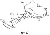
- FIGS. 6A and 6Brespectively illustrate assembled and component views of a provisional tibial prosthesis system 340 and a shim handling instrument 354 attachable to a shim component 346 of the system.
- the shim handling instrument 354can be used for insertion or removal of different sized shim components 346.
- the shim handling instrument 354can include, among other things, a handle body 602, a user-engageable end 604, an opposing attachment end 606, one or more alignment pins 608, release means 356 (e.g., a release button), and an engageable tooth 610.
- the one or more alignment pins 608can be positioned on each side of the engageable tooth 610.
- the alignment pins 608can be configured to fit into respective handling alignment voids 477 positioned near an anterior side 467 of the shim component 346.
- the engageable tooth 610can be configured to slide along a shim ramp 612.
- a biasing force on the engageable tooth 610can cause the tooth to travel downward and engage a backside of the shim ramp 612, thereby locking the shim handling instrument 354 to the shim component 346.
- the biasing forcecan be exerted on the engageable tooth 610 by a tension spring.
- a surgeon holding the user-engageable end 604 of the shim handling instrument 354can insert the shim component 346 between a bearing component 342 and a bearing support component, such as one or both of a base component 344 or a plate component 350, in an anterior/posterior direction 210 ( FIG. 2 ).
- the insertion of the shim component 346can space the bearing component 342 from the bearing support component a distance equal to the shim component height 347 ( FIG. 4A ) along a proximal/distal axis 204 ( FIG. 2 ).
- an entry ramp 614 on a posterior side 469 of the shim component 346can be used to urge, in a ramp-like manner, separation of the bearing component 342 and the bearing support component.
- the release means 356can be depressed to overcome the downward biasing force on the engageable tooth 610. In this way, the engageable tooth 610 can be disengaged from the backside of the shim ramp 612 and the shim handling instrument 354 can be disengaged from the shim component 346.
- the shim handling instrument 354can be used to remove the shim component 346 from between the bearing component 342 and the bearing support component.
- the present provisional tibial prosthesis system 340can be adjusted in a manner requiring a knee joint 114 ( FIG. 2 ) to only be distracted by a distance equal to a height profile of the shim component 346.
- the shim components 346as shown in FIGS. 8 and 10 , can include one or both of a medial edge having a different height than a lateral edge or an anterior edge having a different height than a posterior edge. Differing height shim components 346 can advantageously provide a surgeon with joint kinematic insight regarding an angled bone cut before the cut is made, and can reduce the number of provisional components needed during surgery sizing by offering tailored separation between knee joint components.
- the bearing component 342 and the bearing support component, such as the base component 344do not have to be removed from the knee joint 114 to insert and remove shim components 346.
- FIGS. 7 and 8illustrate front views of at least two versions of a shim component of a provisional tibial prosthesis system.
- the shim component 346A of FIG. 7includes a medial edge height 702 that is the same or substantially the same as a lateral edge height 704.
- the shim component 346B of FIG. 8includes a medial edge height 702 that is different than a lateral edge height 704.
- the medial edge height 702is greater than the lateral edge height 704 and can be used by a surgeon to analyze possible bone cuts for a patient experiencing a varus (or bow-legged) knee joint.
- the medial edge height 702can be less than the lateral edge height 704 and can be used by a surgeon to analyze possible bone cuts for a patient experiencing a valgus (for knock-kneed) joint. Due to a height difference between the medial and lateral edges, an inferior surface 461 of the shim component can include a medial to lateral angle of between +3 degrees and -3 degrees, inclusive.
- the wedge-like shape of the shim component 346Bcan be used by the surgeon to assess kinematics of a knee joint if a particular bone cut is made. In this way, the wedge-like shape can be used as a feedback mechanism.
- the medial edge height 702 or the lateral edge height 704can provide between 10 mm and 20 mm, inclusive, of spacing adjustment between a bearing component 342 ( FIG. 4A ) and a bearing support component, such as a base component 344 ( FIG. 4A ) or a plate component 350 ( FIG. 4A ). In some examples, the medial edge height 702 or the lateral edge height 704 can provide between 10 mm and 14 mm, inclusive, of spacing adjustment and an additional 0 mm to 6 mm of spacing adjustment can be provided by different sizes of the bearing support component.
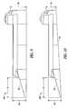
- FIGS. 9 and 10illustrate side views of at least two versions of a shim component of a tibial prosthesis system.
- the shim component 346C of FIG. 9includes an anterior edge height 706 that is the same or substantially the same as a posterior edge height 708.
- the shim component 346D of FIG. 10includes an anterior edge height 706 that is different than a posterior edge height 708.
- the anterior edge height 706is less than the posterior edge height 708 and can be used by a surgeon to analyze possible bone cuts for a patient experiencing an anterior to posterior sloped knee joint.
- the anterior edge height 706can be greater than the posterior edge height 708 and can be used by a surgeon to analyze possible bone cuts for a patient experiencing a poster to anterior sloped knee joint. Due to a height difference between the anterior and posterior edges, an inferior surface 461 of the shim component can include an anterior to posterior angle of between +3 degrees and -3 degrees, inclusive.
- the wedge-like shape of the shim component 346Dcan be used by the surgeon to assess kinematics of a knee joint if a particular bone cut is made. In this way, the wedge-like shape can be used as a feedback mechanism.
- the anterior edge height 706 or the posterior edge height 708can provide between 10 mm and 20 mm, inclusive, of spacing adjustment between a bearing component 342 ( FIG. 4A ) and a bearing support component, such as a base component 344 ( FIG. 4A ) or a plate component 350 ( FIG. 4A ).
- the anterior edge height 706 or the posterior edge height 708can provide between 10 mm and 14 mm, inclusive, of spacing adjustment and an additional 0 mm to 6 mm of spacing adjustment can be provided by different sizes of the bearing support component.
- the shim components 346C and 346Dcan include an entry ramp 709, which can be similar to the entry ramp 614 described above and shown in FIG. 6B .
- a ratio R from a start of the ramp 709 to a beginning of a dovetail of each of the shim components 346C and 346Dcan be used to maintain engagement of the dovetails during a shim insertion procedure.
- FIGS. 11 , 12A , and 12Billustrate exploded views of a base component 344 and a plate component 350 of a tibial prosthesis system 340 ( FIG. 4A ).
- the plate component 350can correspond closely in size and shape with a resected proximal tibial surface.
- the plate component 350can include a superior surface 1102, an opposing bone contacting surface 1104, and a peripheral wall 1106 extending from the bone contacting surface 1104 to the superior surface 1102.
- the peripheral wall 1106can include a raised perimeter, an anterior side 1108, a posterior side 1110, a medial side 1112, and a lateral side 1114.
- the plate component 350can include a PCL cut-out 1116 disposed at the posterior side 1110 to accommodate a posterior cruciate retaining ligament of a knee joint. While the plate component 350 is part of the provisional prosthesis system disclosed herein, it can also be part of a permanent prosthesis system or a sizing system.
- the base component 344can be secured to the plate component 350 by positioning an inferior surface 476 of the base component 344 on the superior surface 1102 of the plate component 350.
- the base component 344can include at least one ramped surface 1122 extending between its inferior surface 476 and its superior surface 352.
- the at least one ramped surface 1122can be configured to engage one or more undercuts 1120 of the plate component 350.
- a dovetail-like engagement, for example, between the at least one ramped surface 1122 and the one or more undercuts 1120can act to inhibit medial/lateral movement between the base 344 and plate 350 components.
- a perimeter undercut surrounding the inferior surface 476 of the base component 344can further mate with the raised perimeter of the plate component 350 to inhibit anterior/posterior and medial/lateral movement between the base 344 and plate 350 components.
- a locking projection 1202can extend from the inferior surface 476 of the base component 344 and can be configured to engage with a locking cavity 1204 extending inferiorly from the superior surface 1102 of the plate component 350. As shown in FIG. 12B , the locking projection 1202 and the locking cavity 1204 can form an interference locking arrangement 1206.
- FIGS. 13 and 14illustrate perspective views of portions of a tibial prosthesis system 720, which can be similar to portions of the tibial prosthesis system 340, described above, and used in preparation for selecting a permanent tibial prosthesis system.
- FIG. 13shows a bearing component 722 and a base component 724.
- the base component 724is also referred to herein as a bearing support component.
- FIG. 14shows the bearing component 722 and the base component 724, similar to FIG. 13 , as well as a spacer component 726 and a fastener 728.
- the tibial prosthesis system 720can be used to mimic a total knee replacement procedure in which a surgeon decides that a posterior-stabilized (PS) implant is suitable for a particular patient.
- PSposterior-stabilized
- One or more portions of the tibial prosthesis system 720can be used with a permanent tibial prosthesis system such as, for example, a PS implant.
- the fastener 728can be used to "lock down" or secure the bearing component 722 to the base component 724.
- the fastener 728can be a lockdown screw.
- FIGS. 15A through 15Dillustrate various perspective views of the bearing component 722 of FIGS. 13 and 14 .
- FIG. 15Ashows a superior or articulating side of the bearing component 722.
- FIG. 15Bshows a portion of the bearing component 722 cut along a midline in an anterior/posterior direction.
- FIG. 15Cshows a portion of the bearing component 722 cut along a midline in a medial/lateral direction.
- FIG. 15Dshows an inferior or underside of the bearing component 722.
- the bearing component 722can include a post 730 extending from an articulating surface 732 and configured to engage with a femoral component, and an aperture 734 configured to receive the fastener 728 (see FIG. 14 ).
- the post 730can include a pocket 736 extending from an inferior side 738 of the bearing component 722.
- the pocket 736can have one or more planar walls in its cross-section geometry (e.g., trapezoidal cross-section geometry) to prevent or eliminate relative displacement between the bearing component 722 and the base component 724.
- the inferior side 738 of the bearing component 722can also include an opening 740 and a bottom portion 739 to receive one or both of the spacer component 726 (see FIG. 14 ) or a shim component, such as the shim component described below and illustrated in FIGS. 17-20 .
- FIG. 16Aillustrates a superior side 746 of the base component 724 and FIG. 16B illustrates an inferior side 748 of the base component 724.
- the base component 724can include a platform 750 between medial and lateral component portions.
- the platform 750can include a post 752 configured to align with the pocket 736 of the bearing component 722, and an aperture 754 configured to align with the aperture 734 of the bearing component 722 and receive the fastener 728.
- the base component 724can be configured such that a plane of symmetry for the post 752 is aligned with an axis of the opening 754. The position of the post 752 can help prevent an incorrect combination of a particular bearing component 722 and a particular base component 724. If a particular bearing component 722 and a particular base component 724 are not intended to be used together, relative positions of the bearing component and the base component features can be offset and insertion of a shim component can be prevented. This prevention can provide an indication of incompatibility.
- the base component 724can include a rail 756 extending around the platform 750 and configured to engage with a shim component.
- FIG. 17illustrates a perspective view of the spacer component 726, which is illustrated in FIG. 14 .
- FIG. 18illustrates a perspective view of a shim component 758.
- the spacer component 726can be available in a thinner size relative to the shim component 758.
- the spacer 726 and the shim component 758can provide a similar function of providing spacing between the bearing component 722 and the base component 724, as similarly described above for shim component 346 (see FIGS. 4A and 4B ).
- the spacer component 726can provide a substantially similar spacing to a spacing provided between the bearing component 722 and the base component 724 when the two components 722 and 724 are assembled.
- the shim component 758can be used in combination with or in lieu of the spacer component 726 to provide additional or tailored (e.g., differing medial/lateral or anterior/posterior) spacing, as described above and further described below.
- the spacer component 726can be part of the tibial prosthesis system 720 as it is implanted in a knee joint. If additional or tailored spacing is needed between the bearing component 722 and the base component 724, the spacer component 726 can optionally be removed and the shim component 758 can be inserted.
- the spacer component 726can be slidably inserted between the bearing component 722 and the base component 724.
- the spacer component 726can include two extensions 760 and 762 configured to extend in an anterior/posterior direction when the spacer component 726 is inserted between the bearing component 722 and the base component 744.
- the extensions 760 and 762can each engage with the inferior side 738 of the bearing component and the superior side 746 of the base component.
- Engagement between the extensions 760 and 762 and one or both of the bearing component 722 and the base component 724can include a dovetail-like engagement.
- the extension 762can include dovetail geometry 763 on an outer portion of the extension 762, which can be used to engage with dovetail geometry on the bearing component 722.
- engagement between the extensions 760 and 762 and the base component 724can include rail geometry 765, which can match and mate with the rail 756 on the base component 724.
- the spacer component 726can include one or more handling alignment voids 764, or other coupling structures, to engage with an interface of a handling instrument, such as the handling instrument 354 ( FIG. 6A ).
- the shim component 758 of FIG. 18can similarly be slidably inserted between the bearing component 722 and the base component 724 and can include a first paddle 770, a second paddle 772, one or more handling voids 773, as well as a cutout feature 774 between the first 770 and second 772 paddles.
- the cutout feature 774can be configured to accommodate the lockdown screw 728.
- portions of the shim component 758can engage with one or both of the bearing component 722 and the base component 744 can include a dovetail-like manner.
- the shim component 758can include dovetail geometry 771, on a top surface, that mate with the bearing component 722 and rail geometry 773 that mate with the base component 724, on a bottom surface.
- one or both of the first 770 and second 772 paddlescan include an entry ramp 776 and 778, respectively, on a top surface of the shim component 758.
- the entry ramps 776 and 778can be similar to the entry ramp 709 shown in FIGS. 9 and 10 .
- the tibial prosthesis system 720can be configured such that the spacer component 726 and the shim component 758 can both accommodate the lockdown screw 728 shown in FIG. 14 .
- the lockdown screw 728( FIG. 14 ) can be available in different sizes and a size of the screw can be selected based, in part, on a spacing between the bearing component 722 and the base component 724. For example, if there is significant spacing between the bearing component 722 and the base component 724, a longer screw can be used as compared to if there is less spacing between the bearing component and the base component 724.
- the shim component 758 of FIG. 18can be available in a plurality of sizes. As described above in reference to the shim component 346, a set of different sized shim components 758 can be provided in a kit to allow for varying levels of adjustment for the provisional tibial prosthesis system 720. Moreover, the shim component 758 of FIG. 18 can be modified to have a height difference between the anterior and posterior edges and/or the medial and lateral edges, as shown in FIGS. 8 and 10 in reference to the shim components 346B and 346D. Shim components having a height difference between the anterior and posterior edges and/or the medial and lateral edges can be included in the kit of different-sized shim components, which can also include different-sized shim components having a uniform height.
- the spacer component 726 and the shim component 768can be used in both left and right tibial prosthesis systems and need not be side-specific.
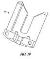
- FIG. 19illustrates another example of a spacer component 780 that can be used in combination with a tibial prosthesis system.
- the spacer component 780can be used with the tibial prosthesis system 340 shown in FIG. 4B .
- the spacer component 780can be used to provide less spacing compared to the shim component 346.
- the spacer component 780can be used, in some examples, to provide approximately the same spacing provided between the base component 344 and the bearing component 342.
- the spacer component 780can be part of the tibial prosthesis system 340 when it is implanted in the knee.
- the spacer component 780can include one or more handling alignment voids for engaging with a handling instrument.
- FIG. 20illustrates an example of a spacer component 784 that can be similar to the spacer component 726 of FIG. 17 and can also include an extension 786.
- a cutout feature 788can be formed in the extension 786 for accommodating a lockdown screw.
- FIG. 21illustrates the spacer component 784 in a tibial prosthesis system 790, which can be similar to the tibial prosthesis system 720.
- the spacer component 784can include the extension 786 and, together with an anterior portion of a bearing component, can form a portion of an aperture 792 configured to receive the fastener 728.
- the tibial prosthesis system 790can be used for smaller size prostheses. As an overall size of the tibial prosthesis gets smaller, less material is available for clamping.
- the extension 786can be used to provide additional material for clamping when a lockdown screw in inserted through the tibial prosthesis system 790 and into the aperture 792.
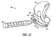
- FIGS. 22-34illustrate an example of a system for determining force balance on a knee joint during a surgical procedure, and the system can include full- or substantially full-surface sensing to determine knee joint kinematics, including soft tissue balance of the knee joint.
- the systemcan include, among other things, a user interface for displaying the sensed data as a two- or three-dimensional representation of an area or volume of the prosthesis, such as an articulation surface area of a tibial prosthesis.
- the various components of the systemcan be provided as a kit, as described below in reference to FIG. 29 .
- FIG. 22illustrates an example of a provisional or trial prosthesis system 800 for use in a knee surgery to provide full- or substantially full-surface sensing.
- the system 800can be used in combination with a user interface for displaying sensing data.
- the trial prosthesis system 800can include one or more of a provisional femoral prosthesis 802, a provisional tibial prosthesis system 804, and a handling instrument 806.
- the provisional tibial prosthesis system 804can be similar to the provisional tibial prosthesis systems described above, and can include a bearing component 808, a shim component 810, a base component 812, and a plate component 814.
- the base component 812 and/or the plate component 814are also referred to herein as a bearing support component.
- FIGS. 23A and 23Brespectively illustrate assembled and component views of the bearing component 808.
- the bearing component 808can be similar to the unitary bearing component 342 shown in FIG. 4B , or can include a plurality of components, such as a top portion 816, a frame 818, a sensor plate 820, and a bottom portion 823.
- the sensor plate 820can include one or both of a plurality of sensors 822 or a processor 824, which can be disposed on a top surface 826 of the sensor plate 820.
- the frame 818can include a plurality of apertures or openings 828 that can be sized and/or shaped to correspond to the plurality of sensors 822 on the sensor plate 820, thereby providing for precise force or pressure sensing.
- the top portion 816 of the bearing component 808can include an articulating side 830 and a non-articulating side 832.
- the bottom portion 823 of the bearing componentcan be configured to support the sensor plate 820 and can form a bottom non-articulating side 834 of the bearing component 808.
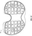
- FIG. 24illustrates the top surface 826 of the sensor plate 820, including the sensors 822 and the processor 824.
- the sensor plate 820can include twenty-four sensors 822.
- a configuration and quantity of the sensors 822, as well as the frame 818,can be different than what is shown in FIG. 23B .
- the bearing component 808can be configured such that there are multiple sensors 822 on the sensor plate 820 and the apertures 828 on the frame 818 can correspond to the sensors 822 in size, shape, or quantity.
- the sensors 822can include any suitable force or pressure sensors or readers, such as, but not limited to, piezoelectric sensors, force sensing resistors, force gauges, strain gauges, load cells, potentiometers, barometers, or the like.
- Example force sensorsinclude force sensing resistor or capacitive flex circuits, piezoelectric film, piezoelectric elements, piezoresistive and piezoelectric polymers, metal foil strain gages, semiconductor strain gages, piezoresistive and capacitive pressure sensors, interferometric optical sensors, path displacement optical sensors, optical fiber force sensors, and other suitable sensing technologies.
- the sensors 822can occupy a substantial portion of the top surface 826 of the sensor plate 820 such that the sensors align with a substantial portion of the superior articulating surface of the bearing component 808, which can be an articulating side 830 of the top portion 816.
- the sensor plate 820can have a medial side M, a lateral side L, an anterior side A, and a posterior side P, all of which can similarly apply to other components of the tibial prosthesis system 804.
- the sensors 822can facilitate precise sensing on both the medial M and lateral L sides and/or anterior A and posterior P sides.
- the sensors 822can facilitate deep posterior sensing, as represented by a medial posterior region 846 and a lateral posterior region 848 in FIG. 24 .
- Posterior sensingcan be beneficial when determining high-flex balance and roll-back, and/or to predict wear, for example. Data gathered from the sensors 822 is described further below in reference to FIGS. 30-34 .
- FIG. 25illustrates the frame 818 and the non-articulating side 832 (or underside) of the top portion 816.
- the non-articulating side 832 of the top portion 816can include a plurality of projections 850, each of which can be sized and shaped to fit within a corresponding aperture 828 on the frame 818.
- the plurality of projections 850can be separate from, and positioned below, the top portion 816.
- the apertures 828 on the framecan be configured to correspond and align with the sensors 822.
- the projections 850can be configured to transfer a representative force to one or more sensors 822 aligned with such force.
- the articulating side 830 of the top portion 816can include inherent flexibility (e.g., via material properties or thickness) to allow applied forces to be appropriately measured by the aligned sensors 822 and processed for one or more knee joint balance determinations.
- the isolated sensing compartments created by distinct projections 850 and distinct apertures 828 of the frame 818can ensure that only forces applied directly above a particular one or more sensors 822 are measured.
- the projections 850can be formed of the same or a different material than other portions of the top portion 816, and such material can be any material used in surgical procedures and having sufficient strength to sufficiently transfer force.
- the projections 850, or a portion thereofcan be formed of metal.
- the top portion 816can be formed through injection molding, and the projections 850 can be inserted into cavities of the top portion 816.
- the cavities of the top portion 816can extend in a proximal-to-distal or distal-to-proximal direction and can correspond to a size and shape of the projections 850.
- Other designscan be used for the top portion 816 and the projections 850 in addition to what is shown in FIG. 25 .
- the articulating side 830can be formed from a separate piece attachable to one or more other components used to form the top portion 816.
- the projections 850can occupy a larger depth of the top portion 816, defined as a distance between the articulating side 830 and the non-articulating side 832. Once in place, the projections 850 can extend through a bottom of the top portion 816.
- FIGS. 26A through 27Cillustrate different components of the provisional tibial prosthesis system 804 in use with a handling instrument 806 shown in FIG. 22 .
- This usecan be similar to the shim handling instrument 354 shown in FIG. 6A and used with the provisional tibial prosthesis system 340.
- FIG. 26Ashows the plate component 814 of the tibial prosthesis system 804 attached to the handling instrument 806.
- the plate component 814can be attached to the handling instrument 806 using a handling alignment void 852 in an anterior portion of the plate component 814.
- FIG. 26Bshows the bearing component 808 attached to the handling instrument 806 using a handling alignment void 854 formed in an anterior portion of the bearing component 808.
- the handling instrument 806can be configured to releasably secure various components of the tibial prosthesis system 804, as further shown in FIG. 27A .
- the handling instrument 806can be configured to engage with one handling void in the component it secures.
- the handling instrument 806can be configured to engage with two handling voids in the component it secures.
- the bearing component 808, the base component 812, and the plate component 814can be assembled together in preparation for implanting the tibial prosthesis system 804 on a tibia, and the handling instrument 806 can be attached to the plate component 814, as shown in FIG. 22 .
- the shim component 810can be included within the tibial prosthesis system 814, as shown in FIG. 22 , when the other components are implanted, or the shim component 810 can be implanted in a later step.
- FIG. 27Aillustrates the shim component 810 attached to the handling instrument 806 with a handling alignment void 856, and prior to inserting the shim component 810 between the bearing component 808 and the base component 812.
- the shim component 810can have a thickness T1 .
- FIG. 27Billustrates additional shim components 858, 860, 862 and 864 of increasing thicknesses (in a proximal to distal direction).
- a thickness T2 of the shim component 858can be greater than the thickness T1 of the shim component 810.
- a thickness T3 of the shim component 860can be greater than the thickness T2 of the shim component 858.
- the shim components 810, 858, 860, 862 and 864can have a thickness range between 10 mm and 14 mm, inclusive.
- a particular shim componentcan be selected for insertion based on a distance between the bearing component 808 and the base component 812 implanted on a tibia. Also, as described above in reference to the method 500 of FIG. 5 , a chosen shim component, selected from the shim components 810, 858, 860, 862 and 864, can be inserted and then testing can be performed to determine if a different shim component should be selected to replace an initially selected shim component. In an example, testing can be performed to analyze a force or pressure balance on at least a portion of the knee joint using the sensors 822 of the bearing component 808.
- the bearing component 808,which includes the sensors 822 and the frame 818, can be configured for providing a comprehensive set of sensing data about a force balance on a knee joint.
- FIG. 27Cillustrates a shim component 866 having a thickness T6.
- the thickness T6 of the shim component 866can be less than the thickness T1 of the shim component 810.
- the thickness T6 of the shim component 866can be about 6 mm. In other examples, the thickness T6 can be less than or greater than 6 mm.
- the shim component 866can be used in combination with one of the shim components 810, 858, 860, 862 and 864 to provide additional spacing between the bearing component 808 and the base component 812.
- the shim component 866can include an aperture 868 for engaging with the handling instrument 806 and can be configured for insertion between a shim component and the bearing component 808.
- the components of the trial prosthesis system 800can be available in varying sizes to accommodate different size knee joints.
- a surgeon or other caregivercan determine an approximate suitable size or shape of the trial prosthesis system 800 using a template.
- FIG. 28illustrates a plurality of templates 880 that can be sized and/or shaped for use in determining a proper tibial tray size prior to selecting a suitable size or shape of the tibial prosthesis system 804.
- the templates 880can range in size from a smallest size A to a largest size F, as shown.
- FIG. 29illustrates an example of a kit 900 that can include a user interface 902, a handling instrument 904, and a plurality of components 906 that can include some or all of the components described above for the trial prosthesis system 800, or related variants of such components also described above.
- the user interfacecan be configured to be connected to the sensors 822 and the processor 824 of the bearing component 808 of the tibial prosthesis system 804.
- the user interface 902can include a computing device configured to process data from the sensors 822 or the processor 824, compare such data to a historical database, and display one or more balance determinations on a screen of the user interface.
- the user interface 902can be configured to be small and portable, as well as wireless, such that the user interface 902 can be used in an area, or surrounding area, of a surgical procedure.
- the user interface 902can be connected to another display device such as, for example, a computer or TV monitor in the area of the surgical procedure.
- the kit 900can include all components for the trial prosthesis system 800, including the provisional femoral prosthesis 802 and a plurality of shim components, as described above in reference to FIG. 27B .
- the kit 900can include at least one shim component having a height difference between the anterior and posterior edges and/or the medial and lateral edges.
- the kit 900can be designed such that the user can have some or all of the components for the knee procedure located together.
- the components of the kit 900can be housed inside a tray 907 that, together with one or more of the components that it houses, can be disposable after a single use.
- the kit 900can include some of the components of the trial prosthesis system 800 and some of the other components can be provided separately during the surgical procedure.
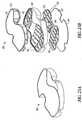
- FIG. 30illustrates an example of a digital image 908 that can be generated and displayed on the user interface 902.
- the bearing component 808 of the tibial prosthesis system 804can include the sensor plate 820 having the plurality of sensors 822.
- the sensor plate 820can have a twenty-four sensor configuration.
- the sensor plate 820can include the processor 824, which can be configured to receive and process data from the plurality of sensors 822 before communicating the data to the user interface 902.
- the processor 824can alternatively be integrated with the computing device of the user interface 902.
- the user interface 902can have a wired or wireless connection with the sensor plate 820.
- the wired or wireless connectioncan utilize any type of network, such as the Internet, a telephone network, a cable network, or a wireless network.
- the digital image 908can be a two-dimensional (shown), or optionally three-dimensional, representation of the area of the tibial prosthesis 800 that is aligned with the sensors 822.
- the data from the sensors 822can be mapped into a multi-point data registry.
- a 24-point data registryis mapped based on having twenty-four sensors 822.
- the data registrycan have more or less than twenty-four points based on having more or less than twenty-four sensors 822 on the sensor plate 820.
- a configuration and design of the bearing component 808, including the frame 818 having the openings 828 aligned with the sensors 822can allow for independent sensing areas that can be noticeably mapped and presented on the user interface 902.
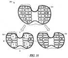
- FIG. 31illustrates an example of a digital image 910 that can be displayed on the user interface 902.
- the digital image 912can show a force value generated by each of the sensors 822 on the sensor plate 820.
- the force value generatedcan be the result of force transmitted by the projections 850 of the top portion 816, or alternatively, columns extending between the top portion 816 and the bottom portion 823, which interact with the sensors 822.
- the computing device of the user interface 902can generate an image 914, which can include a collective force in each of two halves or four quadrants on the provisional tibial prosthesis system 804.
- the image 914can include indicators representing medial M, lateral L, anterior A, and posterior P sides, or combinations thereof, of the provisional tibial prosthesis system.
- An image 916 showing medial-lateral and anterior-posterior center of force datacan also be generated by the user interface 902.
- FIG. 32illustrates an example of another digital image 918 that can be displayed on the user interface 902.
- the surgeon or other usercan select a particular zone, which can be conceptualized as a green or safe zone, representing acceptable force limits in flexion and/or extension.
- the green zonecan be represented by limit points 920 and 922, for example, and in extension, the green zone can be represented by limit points 924 and 926, for example.
- the green zonecan be established based, at least in part, on statistically relevant historical data from one or more patient trials.
- datamay be statistically analyzed (either by the analysis program, or another external program) to form suggested pre-determined pressure criteria, i.e., upper and lower limits, to aid the surgeon in recognizing potential elevated pressure readings.
- the suggested pre-determined pressure criteriacan define statistically sound thresholds and allowable limits under certain conditions, and can be constantly adjusted as more information becomes available in the database.
- Forces values generated by, and acquired from, the sensors 822can then be mapped and shown in image 928 of FIG. 33 , for example.
- the image 928can indicate forces or force zones (e.g., medial zone, lateral zone, anterior zone, posterior zone, medial/anterior zone, medial/posterior zone, lateral/anterior zone, or lateral/posterior zone) that are too high (labeled as 930) relative to the green zone, within the acceptable green zone (labeled as 931), and that are too low (labeled as 932) relative to the green zone.
- the computing device of the user interfacecan be configured to compare the acquired force data to green zone data, the latter of which can be stored in software on the user interface's hard drive.
- FIG. 34illustrates the user interface 902 with multiple images based on the green zone selected by the surgeon. One or more images can be used by the surgeon, for example, to correct excessive forces or force zones.
- additional or alternative datacan be displayed to guide the surgeon.
- the numbers presented as force values in FIGS. 31-34are exemplary to show the type of data that can be generated and displayed for use by the surgeon.
- the particular numbers representedare not intended to be limiting, but rather, an example for determining balance or imbalance of the knee joint.
- the force numbers generated by the sensors and mapped into the data point registrycan be compared to previously gathered numbers over time that can be indicative of adequate to inadequate balance and alignment.
- the user interface 902can be configured to include a computing device and the user interface 902 can be provided as part of the kit 900.
- the sensors 822 and the processor 824can be connected to any other type of computing device to generate the types of data described above, based on the data from the sensors 822.
- Existing provisional systems, kits, and methodsfail to provide a surgeon with insight of knee joint kinematics if an angled bone cut (e.g., a bone cut that is not parallel to a joint line of a knee) is made to a distal end of a femur or a proximal end of a tibia.
- Existing provisional systems, kits, and methodsfurther require the stacking of a relatively high number of provisional components to arrive at an appropriate configuration of a permanent tibial prosthesis system or fail to provide sensed force or pressure data providing a real-time indication of provisional knee joint balance.
- the present provisional systems, kits, and methodscan include a shim component, having one or both of a medial edge height that is different than a lateral edge height or an anterior edge height that is different than a posterior edge height, or a sensor coupled to or integrated with a bearing component, a bearing support component, or the shim component.
- a shim component configurationcan provide the surgeon with knee joint kinematic insight regarding an angled bone cut to the femur or tibia before the cut is made and can reduce the number of provisional components needed during surgery sizing.
- the sensorcan facilitate real-time knee joint balancing testing.
- the terms “a” or “an”are used to include one or more than one, independent of any other instances or usages of “at least one” or “one or more.”
- the term “or”is used to refer to a nonexclusive or, such that “A or B” includes “A but not B,” “B but not A,” and “A and B,” unless otherwise indicated.
- anteriorrefers to a direction generally toward the front of a patient
- posteriorrefers to a direction generally toward the back of the patient
- “medial”refers to a direction generally toward the middle of the patient
- “lateral”refers to a direction generally toward the side of the patient.
- the phrase “anterior/posterior direction”is used to include an anterior to posterior direction or a posterior to anterior direction.
Landscapes
- Health & Medical Sciences (AREA)
- Orthopedic Medicine & Surgery (AREA)
- Life Sciences & Earth Sciences (AREA)
- Transplantation (AREA)
- General Health & Medical Sciences (AREA)
- Oral & Maxillofacial Surgery (AREA)
- Engineering & Computer Science (AREA)
- Biomedical Technology (AREA)
- Heart & Thoracic Surgery (AREA)
- Animal Behavior & Ethology (AREA)
- Public Health (AREA)
- Veterinary Medicine (AREA)
- Vascular Medicine (AREA)
- Cardiology (AREA)
- Physical Education & Sports Medicine (AREA)
- Biophysics (AREA)
- Surgery (AREA)
- Nuclear Medicine, Radiotherapy & Molecular Imaging (AREA)
- Dentistry (AREA)
- Physics & Mathematics (AREA)
- Pathology (AREA)
- Medical Informatics (AREA)
- Molecular Biology (AREA)
- Prostheses (AREA)
- Surgical Instruments (AREA)
Description
- This patent document pertains generally to tibial prosthesis systems. The closest prior art is document
US 5470354 , which defines the preamble of claim 1. - Provisional knee prosthesis systems, including a plurality of provisional components, can be positioned on a distal end of a femur or a proximal end of a tibia to allow a surgeon to test and appropriately fit a permanent knee prosthesis system within a patient. During surgery, the surgeon can remove and replace a provisional component having a first uniform thickness with a provisional component having a second uniform thickness to arrive at an appropriate configuration of the permanent knee prosthesis system.
- This patent document pertains generally to provisional tibial prosthesis systems, kits, and methods, including one or more provisional tibial components that can collectively be used to replicate permanent (or final) tibial components or mimic bone cuts believed to be necessary during a surgical procedure. It is believed that the provisional tibial components can also be designed for, or find use as, permanent tibial components. Thus, while this disclosure relates to provisional uses of the present tibial prosthesis systems, kits, and methods, it should be appreciated that such subject matter can also find use in permanent applications. When used provisionally, the tibial prosthesis systems, kits, and methods disclosed herein can assist in determining a proper bone cut angle to be made (e.g., to a tibia or a femur) or a size, shape, or other configuration of a permanent tibial prosthesis system that is designed to replace all or a portion of a knee joint.
- The present inventors recognize, among other things, that existing provisional systems, kits, and methods fail to provide a surgeon with insight of knee joint kinematics if an angled bone cut (e.g., a bone cut that is not parallel to a joint line of the knee) is made to a proximal end of the tibia or a distal end of the femur. The present inventors further recognize that existing provisional systems, kits, and methods require the stacking of a high number of provisional components to arrive at an appropriate configuration of the permanent tibial prosthesis system or fail to provide sensed force or pressure data providing a real-time indication of provisional knee joint balance.
- The invention is defined in claim 1.
- The present shim components, which can include one or both of a medial edge having a different height than a lateral edge or an anterior edge having a different height than a posterior edge, advantageously provide a surgeon with knee joint kinematic insight regarding an angled bone cut before the cut is made and can reduce the number of provisional components needed for permanent system sizing. The present shim components can provide the surgeon with the ability to appropriately configure the tibia, the femur, and/or the permanent tibial prosthesis system to counterbalance a deficiency (e.g., varus, valgus, anterior/posterior, or posterior/anterior sloping) of the knee joint before making certain angled bone cuts and using a reduced number of provisional components.
- A tibial prosthesis system can include a provisional bearing component, a bearing support component, such as a base or plate component, and the provisional shim component. The shim component can be inserted between an inferior surface of the bearing component and a superior surface of the bearing support component. The insertion of the shim component provides spacing adjustment between the bearing and bearing support components. A sensor can be coupled to or integrated with the bearing, bearing support, or shim components for real-time knee joint balance testing.
- Examples and features of the present systems will be set forth in part in the following Detailed Description. This Overview is intended to provide non-limiting examples of the present subject matter-it is not intended to provide an exclusive or exhaustive explanation. The Detailed Description below is included to provide further information about the present tibial prosthesis systems.
- In the drawings, like numerals can be used to describe similar elements throughout the several views. Like numerals having different letter suffixes can be used to represent different views or features of similar elements. The drawings illustrate generally, by way of example, but not by way of limitation, various embodiments discussed in the present document.
- FIGS. 1-2
- illustrate knee joint structures providing suitable environments in which a tibial prosthesis system can be used.
- FIG. 3
- illustrates a partially resected knee joint structure and a tibial prosthesis system.
- FIGS. 4A-4B
- respectively illustrate assembled and component views of a tibial prosthesis system.
- FIG. 5
- illustrates a method of using a tibial prosthesis system.
- FIG. 6A-6B
- respectively illustrate assembled and component views of a tibial prosthesis system and a shim handling instrument.
- FIGS. 7-8
- illustrate front views of a shim component of a tibial prosthesis system.
- FIGS. 9-10
- illustrate side views of a shim component of a tibial prosthesis system.
- FIGS. 11-12B
- illustrate exploded views of a base component and a plate component of a tibial prosthesis system.
- FIGS. 13-14
- illustrate perspective views of portions of a tibial prosthesis system.
- FIGS. 15A-15D
- illustrate various perspective views of a bearing component.
- FIGS. 16A-16B
- illustrate superior and inferior sides, respectively, of a base component.
- FIG. 17
- illustrates a perspective view of a spacer component.
- FIG. 18
- illustrates a perspective view of a shim component.
- FIGS. 19-20
- illustrate perspective views of a spacer component.
- FIG. 21
- illustrates a perspective view of a spacer component positioned in a tibial prosthesis system.
- FIG. 22
- illustrates a perspective view of a provisional or trial prosthesis system, as constructed in accordance with at least one embodiment.
- FIGS. 23A-23B
- illustrate assembled and component views, respectively, of a bearing component, as constructed in accordance with at least one embodiment.
- FIG. 24
- illustrates a top surface of a bearing component sensor plate, as constructed in accordance with at least one embodiment.
- FIG. 25
- illustrates a frame and a non-articulating side of a bearing component top portion, as constructed in accordance with at least one embodiment.
- FIGS. 26A-27C
- illustrate one or more components of a provisional tibial prosthesis system in use with a handling instrument.
- FIG. 28
- illustrates a plurality of templates for determining a proper tibial tray size prior to selecting a tibial prosthesis system.
- FIG. 29
- illustrates an example of a kit that can include a user interface, a handling instrument, and a plurality of components of a trial prosthesis system.
- FIGS. 30-34
- illustrate digital images that can be generated and displayed on a user interface.
- The present inventors recognize that it can be desirable to provide surgeons with knee joint kinematic insight before certain bone cuts are made (e.g., to a tibia or a femur) and with the ability to quickly create a configuration appropriate for a permanent tibial prosthesis system using provisional components. The present tibial prosthesis systems, kits, and methods can include a provisional bearing component, a bearing support component, such as a base component or a plate component, and a provisional shim component. The shim component can include one or both of a medial edge having a different height than a lateral edge or an anterior edge having a different height than a posterior edge and can be inserted between the bearing component and the bearing support component. The differing height profile of the shim component can provide a surgeon with knee joint kinematic insight regarding an angled bone cut before the cut is made and can allow for sizing of an appropriate permanent prosthesis component configuration using a reduced number of provisional components. A sensor can be coupled to or integrated with the bearing, bearing support, or shim components for real-time knee joint balance testing.
- To better understand knee joint replacement procedures, it can be helpful to understand the relationship of bones and bone cuts that can be made to orient various provisional and permanent prosthesis components within a knee joint.
FIGS.1 and2 illustrate several features of knee joint structures and orientations. InFIG.1 , a frontal view of alower limb 102, including afemur 104 and atibia 106, is shown to illustrate various lower limb axes. Thefemur 104 has ananatomic axis 108 that coincides generally with its intramedullary canal. Thefemur 104 also has amechanical axis 110, or load axis, running from the center of afemoral head 112 to the center of aknee joint 114. Theangle 116 extending between these two axes varies among the patient population, but is generally on the order of between 5-7 degrees, inclusive. Like thefemur 104, thetibia 106 also has an anatomic axis coinciding generally with its intramedullary canal. Themechanical axis 118 of thetibia 106 runs from the center of the knee joint114 to the center of anankle region 120 and is generally collinear with its anatomic axis. - A
joint line 122, about which the knee joint114 flexes, is approximately parallel to a line through medial and lateralfemoral condyles 124 and to atibial plateau 126. Although illustrated as perpendicular inFIG.1 , thejoint line 122 can extend at a varus or valgus angle relative to themechanical axes femur 104 andtibia 106, respectively. Normally, during a partial or total knee replacement procedure, portions of a distal end of thefemur 104 or a proximal end of thetibia 106 are resected to be parallel or approximately parallel to thejoint line 122, and thus perpendicular to themechanical axes FIG.2 illustrates a closer view of the knee joint114 and its coordinate system, in which a medial/lateral axis 202 corresponds approximately to the joint line122 (FIG.1 ), a proximal/distal axis 204 corresponds approximately to themechanical axes 110 and118 (FIG.1 ), and an anterior/posterior axis 206 is approximately normal to the other two axes. Position along each of these axes can be depicted by arrows, which can represent the medial/lateral 208, anterior/posterior 210, and proximal/distal212 positioning of inserted prosthesis components. Rotation about each of these axes can also be depicted by arrows. Rotation about the proximal/distal axis 204 can correspond anatomically to external rotation of a femoral component, while rotation about the anterior/posterior axis 206 and medial/lateral axis 202 can correspond to extension plane slope and varus/valgus angle of a component, respectively. Depending on a position of the proximal tibial cut130 (FIG.1 ) made, a varus/valgus angle 214,extension plane angle 216,external rotation 218, or joint extension gap can be affected. Similarly, a position of the distal femoral cut128 (FIG.1 ) can affect the location of thejoint line 122, the extension gap, the varus/valgus angle 214, or theextension plane angle 216.FIG.3 illustrates a partially resected knee joint314 structure, including a proximal tibial cut130, and a provisionaltibial prosthesis system 340. The provisionaltibial prosthesis system 340 can include abearing component 342, abase component 344, aplate component 350, and ashim component 346 insertable between aninferior surface 348 of thebearing component 342 and asuperior surface 352 of thebase component 344. Theshim component 346 can include one or both of a medial edge having a different height than a lateral edge or an anterior edge having a different height than a posterior edge and can be used as a height varying spacer block between the bearingcomponent 342 and thebase component 344. The spacing of thebearing component 342 from thebase component 344, for example, is adjustable to allow for representation of a variety of different sized angled bone cuts that can be made to afemur 104 or atibia 106 or permanent tibial prosthesis systems. Theshim component 346 can be inserted between theinferior surface 348 of thebearing component 342 and thesuperior surface 352 of thebase component 344 using ashim handling instrument 354. Theshim handling instrument 354 can include a release means356 to disengage theshim component 346 after its insertion between the bearing342 andbase 344 components.FIGS.4A and4B respectively illustrate assembled and component views of a provisionaltibial prosthesis system 340. The provisionaltibial prosthesis system 340, or components thereof, can be used to mimic geometry of one or both of an angle bone cut to be made or a permanent tibial prosthesis system. For example, the assembledtibial prosthesis system 340 ofFIG.4A , illustrates abearing component 342, ashim component 346, abase component 344, and aplate component 350. Astem component 358 can be attached to theplate component 350 and used to secure theplate component 350 to a resected tibia106 (FIG.3 ).- Each component of the provisional
tibial prosthesis system 340 includes an associated height. Ashim component height 347 can be combined with a bearingcomponent height 343 and abase component height 345, for example, to represent a desired height of a permanent tibial prosthesis system. A plurality of different or varyingsized shims 346 can be slidably inserted between the bearingcomponent 342 and a bearing support component, such as thebase component 344, in an anterior/posterior 210 direction. Advantageously, the different or varyingsized shims 346 can be inserted and removed without removing thebearing component 342 or the bearing support component from within a knee joint314 (FIG.3 ). Instead, all that is needed is a distraction of the knee joint314 in an amount equal or approximately equal to the height profile of aparticular shim component 346. In one example, theshim handling instrument 354 can be used to engage one or more handling alignment voids of ashim component 346 to assist in inserting and removing theshim component 346 between the bearingcomponent 342 and thebearing support component 344. The one or more handling alignment voids of theshim component 346 can be consistent over the broad range of different sized shim components for universal compatibility with theshim handling instrument 354. - Each component of the provisional
tibial prosthesis system 340 can include a structure defined by various surfaces, voids, or cavities. As shown inFig.4B , thebearing component 342, for example, can include aninferior surface 348, an opposingsuperior surface 460, and aperipheral wall 462 extending from theinferior surface 348 to thesuperior surface 460. Thebearing component 342 can further include ananterior side 464, aposterior side 466, alateral side 468, and amedial side 470. Thesuperior surface 460 can be configured to articulate with natural or prosthetic condyles of a distal femur and can include a bearing lateral articular surface portion and a bearing medial articular surface portion, with a centraltibial eminence 472 disposed between the articular surface portions. Theinferior surface 348 can include a bearing cavity and one or more bearing nub cavities. The bearing cavity can extend from theinferior surface 348 toward thesuperior surface 460 and can be sized and shaped to accept a projection of thebase component 344. The bearing nub cavities can extend on opposing sides of the bearing cavity and can each be sized and shaped to receive a nub located on the projection of thebase component 344. - A posterior cruciate ligament (PCL)
cutout 474 can be disposed at theposterior side 466 between the articular surfaces. ThePCL cutout 474 can be sized and positioned to correspond with a PCL of theknee joint 314. In the example ofFIG.4B , thebearing component 342 is illustrated as a cruciate retaining bearing component, although it is contemplated that other tibial bearing components can be used. Bearing components that cooperate to form a posterior stabilized prosthesis, as shown in the example ofFIG.4A , or a knee prosthesis having an intermediate level of constraint between a posterior stabilized and cruciate retaining prosthesis are within the scope of the present disclosure. Thebearing component 342 can also be made available in a variety of shapes and sizes to accommodate a variety of patient knee joints. - The
base component 344 can include aninferior surface 476, an opposingsuperior surface 352, and aperipheral wall 480 extending from theinferior surface 476 to thesuperior surface 352. Thebase component 344 can further include ananterior side 481, aposterior side 482, alateral side 484, and amedial side 486. Aprojection 488, including one ormore nubs 490, can extend from thesuperior surface 352. Theprojection 488 andnubs 490 can be configured to be received within, and couple to, the bearing and bearing nub cavities of thebearing component 342. Thebase component 344 can include one or more of a W-shapednotch 492 at theposterior side 482, an undercut portion to mate with a raised perimeter of theplate component 350, a medial side groove, and a lateral side groove. - The
bearing component 342 and thebase component 344 can be coupled to or engaged with each other. In an example, thebearing component 342 can be positioned atop of thebase component 344 and theprojection 488, including the one ormore nubs 490, of thebase component 344 can be positioned within the bearing and bearing nub cavities of thebearing component 342. Thebase component 344 can be secured to thebearing component 342 in a medial/lateral direction208 (FIG.2 ) when theprojection 488 is received with the bearing cavity and can be secured in an anterior/posterior direction210 (FIG.2 ) when the one ormore nubs 490 are received with respective nub cavities. The walls of the bearing cavity can provide a physical barrier to inhibit significant relative movement between thebase component 344 and thebearing component 342 in the medial/lateral direction 208. Similarly, the walls of the bearing nub cavities can provide a physical barrier to inhibit significant relative movement between thebase component 344 and thebearing component 342 in the anterior/posterior direction 210. When thebearing component 342 is positioned atop thebase component 344, and before insertion of theshim component 346, the bearing component can342 be movable relative to thebase component 344 in a proximal/distal direction212 (FIG.2 ). - As further discussed with respect to and illustrated in
FIGS.11 and12 , below, thebase component 344 can be secured to thebase plate 350, such that thebase component 344 is located between the bearingcomponent 342 and thebase plate 350. - Turning again to
FIG.4B , theshim component 346 can include aninferior surface 461, an opposingsuperior surface 463, and aperipheral wall 465 extending from theinferior surface 461 to thesuperior surface 463. Theperipheral wall 465 can define an exterior profile of theshim component 346. In an example, the exterior profile of theshim component 346 can substantially match an exterior profile of thebase component 344 or theplate component 350. Theshim component 346 can further include ananterior side 467, aposterior side 469, alateral side 471, and amedial side 473. - The
superior surface 463 can include one ormore rails 475 and one or more handling alignment voids477. The one ormore rails 475 can be configured to slidably engage one or more slots on theinferior surface 348 of thebearing component 342. Therails 475 can extend from theanterior side 467 toward theposterior side 469, such in an orientation parallel to the anterior/posterior direction 210. Therails 475 can include lead-inedges 479 to facilitate alignment and engagement with the slots of thebearing component 342. Therail 475/slot engagement between theshim component 346 and thebearing component 342 can inhibit lift-off thebearing component 342 from theshim component 346. The one or more handling alignment voids477 can be configured to engage with an interface of a shim handling instrument, such as is shown inFIG.6A . - A set of different
sized shim components 346 can be provided in a kit to allow for varying levels of adjustment of the provisionaltibial prosthesis system 340 and insight into knee joint kinematics if certain bone cuts are made to a tibia106 (FIG.1 ) or a femur104 (FIG.1 ). Particularly, the distance between the bearingcomponent 342 and thebase component 344 can be increased or decreased by inserting and removing differentsized shim components 346. At least one of theshim components 346 can include one or both of a medial edge having a different height than a lateral edge or an anterior edge having a different height than a posterior edge. The medial edge height and the lateral edge height can be sized such that theinferior surface 461 of theshim component 346 includes a medial to lateral angle of between +3 degrees and -3 degrees, inclusive. The anterior edge height and the posterior edge height can be sized such that theinferior surface 461 of theshim component 346 includes an anterior to posterior angle of between +3 degrees and -3 degrees, inclusive. Two ormore shim components 346 from the set can, in an example, be stacked to achieve desirable knee joint kinematics. It is believed that the set of differentsized shim components 346 can include any desired number of shims having a constant or differing height. FIG.5 illustrates amethod 500 of using a provisional tibial prosthesis system to determine a proper angle of a bone cut to be made, if any, and an appropriate size (e.g., height) for a permanent tibial prosthesis system in a knee joint. At502, a surgeon or other caregiver selects a particular size of the provisional tibial prosthesis system believed to be suitable for a patient. The provisional tibial prosthesis system can include a bearing member, a bearing support component, comprising one or both of a base component or a plate component, and a shim component. The plate component can include an inferior surface configured to contact a resected portion of a tibia and an opposing superior surface. The base component can include a base component height and be attachable to the plate component. The bearing component can include a bearing component height, and the shim component can include a shim component height. The shim component can be configured to be slidably received between the bearing component and the bearing support component in an anterior/posterior direction.- At504, a proximal end portion of the patient's tibia is resected to be parallel or approximately parallel to a joint line of a knee. The tibia can be resected using standard surgical techniques to provide a substantially flat surface for receipt of the inferior, bone contacting surface of the plate component. Once the proximal end portion of the tibia is resected, the plate component can be implanted and secured to the resected tibia, at506.
- At508, one or more of the selected bearing, shim, and base components can be positioned atop the plate component. In an example, the selected bearing and base components can initially be positioned atop the plate component, and subsequently, the selected shim component can be inserted between the bearing and base components in the anterior/posterior direction. The inserted shim component can include one or both of a medial edge having a different height than a lateral edge or an anterior edge having a different height than a posterior edge to counterbalance a deficiency (e.g., varus, valgus, anterior/posterior, or posterior/anterior sloping) of the knee joint.
- At510, the surgeon can perform one or more of a stability, a force balance, or a range of motion test of the knee joint to determine whether proper joint kinematics are present. The testing can include sensing at least one of a pressure, force, or position of the knee joint using a sensor coupled to or integrated with a provisional component. If the surgeon determines that proper knee joint kinematics is present, sizing procedures can begin, at516. The sizing procedures can include determining whether an angled bone cut to the tibia and/or femur (e.g., a bone cut that is not parallel to the joint line of the knee) is needed, at517, such as to counterbalance the knee joint deficiency, or determine the height of the provisional tibial prosthesis system. The angled bone cut to the tibia and/or femur can correspond to a height profile of the selected shim. The sizing procedures can use a sizing guide including alignment pins that fit in respective exterior voids in one or more provisional components to properly align the sizing guide to the components. Once properly aligned, a locking component of the sizing guide can slide along a shim ramp, for example, and, when the locking component slides past the shim ramp, a biasing force on the locking component can cause the locking component to travel downward and engage a backside of shim ramp to lock the sizing guide to the shim component.
- At512, if the provisional tibial prosthesis system is determined to not be properly sized due to improper joint kinematics being present, an additional or different sized shim component can be selected. At514, the originally selected shim component can be removed from between the bearing component and the bearing support component and/or the newly selected shim component can be inserted between the bearing component and the bearing support component. The newly selected shim component can include at least one of a medial edge, a lateral edge, an anterior edge, or a posterior edge having a different height than the originally selected shim component. Insertion and removal of the shim components can be achieved in the anterior/posterior direction using a shim handling instrument. The bearing and bearing support components can be configured and coupled to each other in such a way that removal or insertion of shim components does not disturb the coupling arrangement.
- With the newly selected shim component in place, the surgeon can again perform one or more of a stability, a force balance, or a range of motion test of the knee joint, at510, to determine whether proper joint kinematics are present. Shim component replacement or stacking can be repeated, using a variety of different or similarly sized shims and a variety of different numbers of shims, until the surgeon determines that proper joint kinematics are present.
- Finally, at518, a permanent tibial prosthesis system can be selected and implanted. The permanent tibial prosthesis system can include a height that corresponds to the height of one or more provisional tibial prosthesis system components.
FIGS.6A and6B respectively illustrate assembled and component views of a provisionaltibial prosthesis system 340 and ashim handling instrument 354 attachable to ashim component 346 of the system. As discussed with respect toFIG.5 , above, theshim handling instrument 354 can be used for insertion or removal of differentsized shim components 346. Theshim handling instrument 354 can include, among other things, ahandle body 602, a user-engageable end 604, an opposingattachment end 606, one or more alignment pins608, release means356 (e.g., a release button), and anengageable tooth 610. The one or more alignment pins608 can be positioned on each side of theengageable tooth 610. The alignment pins608 can be configured to fit into respective handling alignment voids477 positioned near ananterior side 467 of theshim component 346.- When the
shim handling instrument 354 and theshim component 346 are properly aligned, theengageable tooth 610 can be configured to slide along ashim ramp 612. When theengageable tooth 610 slides along theshim ramp 612, a biasing force on theengageable tooth 610 can cause the tooth to travel downward and engage a backside of theshim ramp 612, thereby locking theshim handling instrument 354 to theshim component 346. The biasing force can be exerted on theengageable tooth 610 by a tension spring. - When the
shim handling instrument 354 is locked to theshim component 346, a surgeon holding the user-engageable end 604 of theshim handling instrument 354 can insert theshim component 346 between abearing component 342 and a bearing support component, such as one or both of abase component 344 or aplate component 350, in an anterior/posterior direction210 (FIG.2 ). The insertion of theshim component 346 can space thebearing component 342 from the bearing support component a distance equal to the shim component height347 (FIG.4A ) along a proximal/distal axis204 (FIG.2 ). During insertion of theshim component 346, anentry ramp 614 on aposterior side 469 of theshim component 346 can be used to urge, in a ramp-like manner, separation of thebearing component 342 and the bearing support component. Once theshim component 346 is fully inserted between the bearingcomponent 342 and the bearing support component, the release means356 can be depressed to overcome the downward biasing force on theengageable tooth 610. In this way, theengageable tooth 610 can be disengaged from the backside of theshim ramp 612 and theshim handling instrument 354 can be disengaged from theshim component 346. In a similar manner, theshim handling instrument 354 can be used to remove theshim component 346 from between the bearingcomponent 342 and the bearing support component. - Advantageously, the present provisional
tibial prosthesis system 340 can be adjusted in a manner requiring a knee joint114 (FIG.2 ) to only be distracted by a distance equal to a height profile of theshim component 346. Theshim components 346, as shown inFIGS.8 and10 , can include one or both of a medial edge having a different height than a lateral edge or an anterior edge having a different height than a posterior edge. Differingheight shim components 346 can advantageously provide a surgeon with joint kinematic insight regarding an angled bone cut before the cut is made, and can reduce the number of provisional components needed during surgery sizing by offering tailored separation between knee joint components. Also, thebearing component 342 and the bearing support component, such as thebase component 344, do not have to be removed from the knee joint114 to insert and removeshim components 346. FIGS.7 and8 illustrate front views of at least two versions of a shim component of a provisional tibial prosthesis system. Theshim component 346A ofFIG.7 includes amedial edge height 702 that is the same or substantially the same as alateral edge height 704. In contrast, theshim component 346B ofFIG.8 includes amedial edge height 702 that is different than alateral edge height 704. In the example shown, themedial edge height 702 is greater than thelateral edge height 704 and can be used by a surgeon to analyze possible bone cuts for a patient experiencing a varus (or bow-legged) knee joint. Alternatively, themedial edge height 702 can be less than thelateral edge height 704 and can be used by a surgeon to analyze possible bone cuts for a patient experiencing a valgus (for knock-kneed) joint. Due to a height difference between the medial and lateral edges, aninferior surface 461 of the shim component can include a medial to lateral angle of between +3 degrees and -3 degrees, inclusive. The wedge-like shape of theshim component 346B can be used by the surgeon to assess kinematics of a knee joint if a particular bone cut is made. In this way, the wedge-like shape can be used as a feedback mechanism.- In some examples, the
medial edge height 702 or thelateral edge height 704 can provide between 10 mm and 20 mm, inclusive, of spacing adjustment between a bearing component342 (FIG.4A ) and a bearing support component, such as a base component344 (FIG.4A ) or a plate component350 (FIG. 4A ). In some examples, themedial edge height 702 or thelateral edge height 704 can provide between 10 mm and 14 mm, inclusive, of spacing adjustment and an additional 0 mm to 6 mm of spacing adjustment can be provided by different sizes of the bearing support component. FIGS.9 and10 illustrate side views of at least two versions of a shim component of a tibial prosthesis system. Theshim component 346C ofFIG.9 includes ananterior edge height 706 that is the same or substantially the same as aposterior edge height 708. In contrast, theshim component 346D ofFIG.10 includes ananterior edge height 706 that is different than aposterior edge height 708. In the example shown, theanterior edge height 706 is less than theposterior edge height 708 and can be used by a surgeon to analyze possible bone cuts for a patient experiencing an anterior to posterior sloped knee joint. Alternatively, theanterior edge height 706 can be greater than theposterior edge height 708 and can be used by a surgeon to analyze possible bone cuts for a patient experiencing a poster to anterior sloped knee joint. Due to a height difference between the anterior and posterior edges, aninferior surface 461 of the shim component can include an anterior to posterior angle of between +3 degrees and -3 degrees, inclusive. The wedge-like shape of theshim component 346D can be used by the surgeon to assess kinematics of a knee joint if a particular bone cut is made. In this way, the wedge-like shape can be used as a feedback mechanism.- In some examples, the
anterior edge height 706 or theposterior edge height 708 can provide between 10 mm and 20 mm, inclusive, of spacing adjustment between a bearing component342 (FIG.4A ) and a bearing support component, such as a base component344 (FIG.4A ) or a plate component350 (FIG.4A ). In some examples, theanterior edge height 706 or theposterior edge height 708 can provide between 10 mm and 14 mm, inclusive, of spacing adjustment and an additional 0 mm to 6 mm of spacing adjustment can be provided by different sizes of the bearing support component. - In some examples, the
shim components entry ramp 709, which can be similar to theentry ramp 614 described above and shown inFIG.6B . A ratioR from a start of theramp 709 to a beginning of a dovetail of each of theshim components FIGS.11 ,12A, and12B illustrate exploded views of abase component 344 and aplate component 350 of a tibial prosthesis system340 (FIG.4A ). Theplate component 350 can correspond closely in size and shape with a resected proximal tibial surface. Theplate component 350 can include asuperior surface 1102, an opposingbone contacting surface 1104, and aperipheral wall 1106 extending from thebone contacting surface 1104 to thesuperior surface 1102. Theperipheral wall 1106 can include a raised perimeter, ananterior side 1108, aposterior side 1110, amedial side 1112, and alateral side 1114. Theplate component 350 can include a PCL cut-out1116 disposed at theposterior side 1110 to accommodate a posterior cruciate retaining ligament of a knee joint. While theplate component 350 is part of the provisional prosthesis system disclosed herein, it can also be part of a permanent prosthesis system or a sizing system.- The
base component 344 can be secured to theplate component 350 by positioning aninferior surface 476 of thebase component 344 on thesuperior surface 1102 of theplate component 350. Thebase component 344 can include at least one rampedsurface 1122 extending between itsinferior surface 476 and itssuperior surface 352. The at least one rampedsurface 1122 can be configured to engage one ormore undercuts 1120 of theplate component 350. A dovetail-like engagement, for example, between the at least one rampedsurface 1122 and the one ormore undercuts 1120 can act to inhibit medial/lateral movement between the base344 andplate 350 components. A perimeter undercut surrounding theinferior surface 476 of thebase component 344 can further mate with the raised perimeter of theplate component 350 to inhibit anterior/posterior and medial/lateral movement between the base344 andplate 350 components. To inhibit proximal/distal movement between the base344 andplate 350 components, a lockingprojection 1202 can extend from theinferior surface 476 of thebase component 344 and can be configured to engage with alocking cavity 1204 extending inferiorly from thesuperior surface 1102 of theplate component 350. As shown inFIG.12B , the lockingprojection 1202 and thelocking cavity 1204 can form aninterference locking arrangement 1206. FIGS.13 and14 illustrate perspective views of portions of atibial prosthesis system 720, which can be similar to portions of thetibial prosthesis system 340, described above, and used in preparation for selecting a permanent tibial prosthesis system.FIG.13 shows abearing component 722 and abase component 724. Thebase component 724 is also referred to herein as a bearing support component.FIG.14 shows thebearing component 722 and thebase component 724, similar toFIG.13 , as well as aspacer component 726 and afastener 728. In an example, thetibial prosthesis system 720 can be used to mimic a total knee replacement procedure in which a surgeon decides that a posterior-stabilized (PS) implant is suitable for a particular patient. One or more portions of thetibial prosthesis system 720 can be used with a permanent tibial prosthesis system such as, for example, a PS implant. Thefastener 728 can be used to "lock down" or secure thebearing component 722 to thebase component 724. In an example, thefastener 728 can be a lockdown screw.FIGS.15A through15D illustrate various perspective views of thebearing component 722 ofFIGS.13 and14 .FIG.15A shows a superior or articulating side of thebearing component 722.FIG.15B shows a portion of thebearing component 722 cut along a midline in an anterior/posterior direction.FIG.15C shows a portion of thebearing component 722 cut along a midline in a medial/lateral direction.FIG. 15D shows an inferior or underside of thebearing component 722.- The
bearing component 722 can include apost 730 extending from an articulatingsurface 732 and configured to engage with a femoral component, and anaperture 734 configured to receive the fastener728 (seeFIG.14 ). Thepost 730 can include apocket 736 extending from aninferior side 738 of thebearing component 722. Thepocket 736 can have one or more planar walls in its cross-section geometry (e.g., trapezoidal cross-section geometry) to prevent or eliminate relative displacement between the bearingcomponent 722 and thebase component 724. - The
inferior side 738 of thebearing component 722 can also include anopening 740 and abottom portion 739 to receive one or both of the spacer component726 (seeFIG.14 ) or a shim component, such as the shim component described below and illustrated inFIGS.17-20 . FIG.16A illustrates asuperior side 746 of thebase component 724 andFIG.16B illustrates aninferior side 748 of thebase component 724. Thebase component 724 can include aplatform 750 between medial and lateral component portions. Theplatform 750 can include apost 752 configured to align with thepocket 736 of thebearing component 722, and anaperture 754 configured to align with theaperture 734 of thebearing component 722 and receive thefastener 728.- The
base component 724 can be configured such that a plane of symmetry for thepost 752 is aligned with an axis of theopening 754. The position of thepost 752 can help prevent an incorrect combination of aparticular bearing component 722 and aparticular base component 724. If aparticular bearing component 722 and aparticular base component 724 are not intended to be used together, relative positions of the bearing component and the base component features can be offset and insertion of a shim component can be prevented. This prevention can provide an indication of incompatibility. Thebase component 724 can include arail 756 extending around theplatform 750 and configured to engage with a shim component. FIG.17 illustrates a perspective view of thespacer component 726, which is illustrated inFIG. 14 .FIG.18 illustrates a perspective view of ashim component 758. In an example, thespacer component 726 can be available in a thinner size relative to theshim component 758. Thespacer 726 and theshim component 758 can provide a similar function of providing spacing between the bearingcomponent 722 and thebase component 724, as similarly described above for shim component346 (seeFIGS.4A and4B ). In an example, thespacer component 726 can provide a substantially similar spacing to a spacing provided between the bearingcomponent 722 and thebase component 724 when the twocomponents shim component 758 can be used in combination with or in lieu of thespacer component 726 to provide additional or tailored (e.g., differing medial/lateral or anterior/posterior) spacing, as described above and further described below. In an example, thespacer component 726 can be part of thetibial prosthesis system 720 as it is implanted in a knee joint. If additional or tailored spacing is needed between the bearingcomponent 722 and thebase component 724, thespacer component 726 can optionally be removed and theshim component 758 can be inserted.- As shown in
FIG.14 , thespacer component 726 can be slidably inserted between the bearingcomponent 722 and thebase component 724. Thespacer component 726 can include twoextensions spacer component 726 is inserted between the bearingcomponent 722 and the base component744. Theextensions inferior side 738 of the bearing component and thesuperior side 746 of the base component. Engagement between theextensions bearing component 722 and thebase component 724 can include a dovetail-like engagement. In an example, theextension 762 can includedovetail geometry 763 on an outer portion of theextension 762, which can be used to engage with dovetail geometry on thebearing component 722. In an example, engagement between theextensions base component 724 can includerail geometry 765, which can match and mate with therail 756 on thebase component 724. Thespacer component 726 can include one or more handling alignment voids764, or other coupling structures, to engage with an interface of a handling instrument, such as the handling instrument354 (FIG.6A ). - The
shim component 758 ofFIG.18 can similarly be slidably inserted between the bearingcomponent 722 and thebase component 724 and can include afirst paddle 770, asecond paddle 772, one or more handling voids773, as well as acutout feature 774 between the first770 and second772 paddles. Thecutout feature 774 can be configured to accommodate thelockdown screw 728. Similar to theextensions spacer component 726, portions of theshim component 758 can engage with one or both of thebearing component 722 and the base component744 can include a dovetail-like manner. In an example, theshim component 758 can includedovetail geometry 771, on a top surface, that mate with thebearing component 722 andrail geometry 773 that mate with thebase component 724, on a bottom surface. In an example, one or both of the first770 and second772 paddles can include anentry ramp shim component 758. The entry ramps776 and778 can be similar to theentry ramp 709 shown inFIGS.9 and10 . - The
tibial prosthesis system 720 can be configured such that thespacer component 726 and theshim component 758 can both accommodate thelockdown screw 728 shown inFIG.14 . The lockdown screw728 (FIG.14 ) can be available in different sizes and a size of the screw can be selected based, in part, on a spacing between the bearingcomponent 722 and thebase component 724. For example, if there is significant spacing between the bearingcomponent 722 and thebase component 724, a longer screw can be used as compared to if there is less spacing between the bearing component and thebase component 724. - The
shim component 758 ofFIG.18 can be available in a plurality of sizes. As described above in reference to theshim component 346, a set of differentsized shim components 758 can be provided in a kit to allow for varying levels of adjustment for the provisionaltibial prosthesis system 720. Moreover, theshim component 758 ofFIG.18 can be modified to have a height difference between the anterior and posterior edges and/or the medial and lateral edges, as shown inFIGS.8 and10 in reference to theshim components - The
spacer component 726 and the shim component768 can be used in both left and right tibial prosthesis systems and need not be side-specific. FIG.19 illustrates another example of aspacer component 780 that can be used in combination with a tibial prosthesis system. Thespacer component 780 can be used with thetibial prosthesis system 340 shown inFIG.4B . In an example, thespacer component 780 can be used to provide less spacing compared to theshim component 346. Similar to thespacer component 726, thespacer component 780 can be used, in some examples, to provide approximately the same spacing provided between thebase component 344 and thebearing component 342. As similarly described above in reference to thespacer component 726, thespacer component 780 can be part of thetibial prosthesis system 340 when it is implanted in the knee. Although not visible due to its orientation inFIG.19 , thespacer component 780 can include one or more handling alignment voids for engaging with a handling instrument.FIG.20 illustrates an example of aspacer component 784 that can be similar to thespacer component 726 ofFIG.17 and can also include anextension 786. Acutout feature 788 can be formed in theextension 786 for accommodating a lockdown screw.FIG.21 illustrates thespacer component 784 in atibial prosthesis system 790, which can be similar to thetibial prosthesis system 720. Thespacer component 784 can include theextension 786 and, together with an anterior portion of a bearing component, can form a portion of anaperture 792 configured to receive thefastener 728. In an example, thetibial prosthesis system 790 can be used for smaller size prostheses. As an overall size of the tibial prosthesis gets smaller, less material is available for clamping. Theextension 786 can be used to provide additional material for clamping when a lockdown screw in inserted through thetibial prosthesis system 790 and into theaperture 792.- As described above in the
method 500 ofFIG.5 , after a provisional tibial prosthesis has been implanted in a tibia of a patient, testing can be performed to determine if proper knee joint kinematics are present.FIGS.22-34 illustrate an example of a system for determining force balance on a knee joint during a surgical procedure, and the system can include full- or substantially full-surface sensing to determine knee joint kinematics, including soft tissue balance of the knee joint. The system can include, among other things, a user interface for displaying the sensed data as a two- or three-dimensional representation of an area or volume of the prosthesis, such as an articulation surface area of a tibial prosthesis. The various components of the system can be provided as a kit, as described below in reference toFIG.29 . FIG.22 illustrates an example of a provisional ortrial prosthesis system 800 for use in a knee surgery to provide full- or substantially full-surface sensing. Thesystem 800 can be used in combination with a user interface for displaying sensing data. Thetrial prosthesis system 800 can include one or more of a provisionalfemoral prosthesis 802, a provisionaltibial prosthesis system 804, and ahandling instrument 806. The provisionaltibial prosthesis system 804 can be similar to the provisional tibial prosthesis systems described above, and can include abearing component 808, ashim component 810, abase component 812, and aplate component 814. Thebase component 812 and/or theplate component 814 are also referred to herein as a bearing support component.FIGS.23A and23B respectively illustrate assembled and component views of thebearing component 808. Thebearing component 808 can be similar to theunitary bearing component 342 shown inFIG.4B , or can include a plurality of components, such as atop portion 816, aframe 818, asensor plate 820, and abottom portion 823. Thesensor plate 820 can include one or both of a plurality ofsensors 822 or aprocessor 824, which can be disposed on atop surface 826 of thesensor plate 820. Theframe 818 can include a plurality of apertures oropenings 828 that can be sized and/or shaped to correspond to the plurality ofsensors 822 on thesensor plate 820, thereby providing for precise force or pressure sensing. Thetop portion 816 of thebearing component 808 can include an articulatingside 830 and anon-articulating side 832. Thebottom portion 823 of the bearing component can be configured to support thesensor plate 820 and can form a bottomnon-articulating side 834 of thebearing component 808.FIG.24 illustrates thetop surface 826 of thesensor plate 820, including thesensors 822 and theprocessor 824. In an example, thesensor plate 820 can include twenty-foursensors 822. In other examples, a configuration and quantity of thesensors 822, as well as theframe 818, can be different than what is shown inFIG.23B . Thebearing component 808 can be configured such that there aremultiple sensors 822 on thesensor plate 820 and theapertures 828 on theframe 818 can correspond to thesensors 822 in size, shape, or quantity.- The
sensors 822 can include any suitable force or pressure sensors or readers, such as, but not limited to, piezoelectric sensors, force sensing resistors, force gauges, strain gauges, load cells, potentiometers, barometers, or the like. Example force sensors include force sensing resistor or capacitive flex circuits, piezoelectric film, piezoelectric elements, piezoresistive and piezoelectric polymers, metal foil strain gages, semiconductor strain gages, piezoresistive and capacitive pressure sensors, interferometric optical sensors, path displacement optical sensors, optical fiber force sensors, and other suitable sensing technologies. - The
sensors 822 can occupy a substantial portion of thetop surface 826 of thesensor plate 820 such that the sensors align with a substantial portion of the superior articulating surface of thebearing component 808, which can be an articulatingside 830 of thetop portion 816. Thesensor plate 820 can have a medial sideM, a lateral sideL, an anterior sideA, and a posterior sideP, all of which can similarly apply to other components of thetibial prosthesis system 804. By configuring thesensors 822 to be generally spaced over a substantially portion of a surface that is parallel to, and aligned with, the articulatingside 830 of thetop portion 816, thesensors 822 can facilitate precise sensing on both the medialM and lateralL sides and/or anteriorA and posteriorP sides. Similarly, thesensors 822 can facilitate deep posterior sensing, as represented by a medialposterior region 846 and a lateralposterior region 848 inFIG.24 . Posterior sensing can be beneficial when determining high-flex balance and roll-back, and/or to predict wear, for example. Data gathered from thesensors 822 is described further below in reference toFIGS.30-34 . FIG.25 illustrates theframe 818 and the non-articulating side832 (or underside) of thetop portion 816. Thenon-articulating side 832 of thetop portion 816 can include a plurality ofprojections 850, each of which can be sized and shaped to fit within a correspondingaperture 828 on theframe 818. Alternatively, the plurality ofprojections 850 can be separate from, and positioned below, thetop portion 816.- As described above, the
apertures 828 on the frame can be configured to correspond and align with thesensors 822. Thus, in response to a force on the articulatingside 830 of thetop portion 816, theprojections 850 can be configured to transfer a representative force to one ormore sensors 822 aligned with such force. The articulatingside 830 of thetop portion 816 can include inherent flexibility (e.g., via material properties or thickness) to allow applied forces to be appropriately measured by the alignedsensors 822 and processed for one or more knee joint balance determinations. - The isolated sensing compartments created by
distinct projections 850 anddistinct apertures 828 of theframe 818 can ensure that only forces applied directly above a particular one ormore sensors 822 are measured. Theprojections 850 can be formed of the same or a different material than other portions of thetop portion 816, and such material can be any material used in surgical procedures and having sufficient strength to sufficiently transfer force. In an example, theprojections 850, or a portion thereof, can be formed of metal. - In an example, the
top portion 816 can be formed through injection molding, and theprojections 850 can be inserted into cavities of thetop portion 816. The cavities of thetop portion 816 can extend in a proximal-to-distal or distal-to-proximal direction and can correspond to a size and shape of theprojections 850. Other designs can be used for thetop portion 816 and theprojections 850 in addition to what is shown inFIG.25 . By way of example, the articulatingside 830 can be formed from a separate piece attachable to one or more other components used to form thetop portion 816. In an example, theprojections 850 can occupy a larger depth of thetop portion 816, defined as a distance between the articulatingside 830 and thenon-articulating side 832. Once in place, theprojections 850 can extend through a bottom of thetop portion 816. FIGS.26A through27C illustrate different components of the provisionaltibial prosthesis system 804 in use with ahandling instrument 806 shown inFIG.22 . This use can be similar to theshim handling instrument 354 shown inFIG.6A and used with the provisionaltibial prosthesis system 340.FIG.26A shows theplate component 814 of thetibial prosthesis system 804 attached to thehandling instrument 806. In an example, theplate component 814 can be attached to thehandling instrument 806 using ahandling alignment void 852 in an anterior portion of theplate component 814.FIG.26B shows thebearing component 808 attached to thehandling instrument 806 using ahandling alignment void 854 formed in an anterior portion of thebearing component 808. Thehandling instrument 806 can be configured to releasably secure various components of thetibial prosthesis system 804, as further shown inFIG.27A . In an example, thehandling instrument 806 can be configured to engage with one handling void in the component it secures. In other examples, thehandling instrument 806 can be configured to engage with two handling voids in the component it secures.- In an example, the
bearing component 808, thebase component 812, and theplate component 814 can be assembled together in preparation for implanting thetibial prosthesis system 804 on a tibia, and thehandling instrument 806 can be attached to theplate component 814, as shown inFIG.22 . Theshim component 810 can be included within thetibial prosthesis system 814, as shown inFIG.22 , when the other components are implanted, or theshim component 810 can be implanted in a later step. FIG.27A illustrates theshim component 810 attached to thehandling instrument 806 with a handlingalignment void 856, and prior to inserting theshim component 810 between the bearingcomponent 808 and thebase component 812. In an example, theshim component 810 can have a thicknessT1.FIG.27B illustratesadditional shim components shim component 858 can be greater than the thicknessT1 of theshim component 810. Similarly, a thicknessT3 of theshim component 860 can be greater than the thicknessT2 of theshim component 858. In an example, theshim components - As described above in reference to the
tibial prosthesis system 340, a particular shim component can be selected for insertion based on a distance between the bearingcomponent 808 and thebase component 812 implanted on a tibia. Also, as described above in reference to themethod 500 ofFIG.5 , a chosen shim component, selected from theshim components sensors 822 of thebearing component 808. If the force or pressure data collected is not satisfactory, a different shim component can be inserted. These steps can be repeated until satisfactory force or pressure data is observed. Optionally, in conjunction with or in lieu of shim selection, a surgeon can adjust ligament balance through ligament release if testing balance data is not satisfactory. Thebearing component 808, which includes thesensors 822 and theframe 818, can be configured for providing a comprehensive set of sensing data about a force balance on a knee joint. FIG.27C illustrates ashim component 866 having a thicknessT6. In an example, the thicknessT6 of theshim component 866 can be less than the thicknessT1 of theshim component 810. In an example, the thicknessT6 of theshim component 866 can be about 6 mm. In other examples, the thicknessT6 can be less than or greater than 6 mm. In an example, theshim component 866 can be used in combination with one of theshim components component 808 and thebase component 812. As shown inFIG. 27C , theshim component 866 can include anaperture 868 for engaging with thehandling instrument 806 and can be configured for insertion between a shim component and thebearing component 808.- The components of the
trial prosthesis system 800 can be available in varying sizes to accommodate different size knee joints. In an example, a surgeon or other caregiver can determine an approximate suitable size or shape of thetrial prosthesis system 800 using a template.FIG.28 illustrates a plurality oftemplates 880 that can be sized and/or shaped for use in determining a proper tibial tray size prior to selecting a suitable size or shape of thetibial prosthesis system 804. Thetemplates 880 can range in size from a smallest sizeA to a largest sizeF, as shown. FIG.29 illustrates an example of akit 900 that can include auser interface 902, ahandling instrument 904, and a plurality ofcomponents 906 that can include some or all of the components described above for thetrial prosthesis system 800, or related variants of such components also described above. The user interface can be configured to be connected to thesensors 822 and theprocessor 824 of thebearing component 808 of thetibial prosthesis system 804. Theuser interface 902 can include a computing device configured to process data from thesensors 822 or theprocessor 824, compare such data to a historical database, and display one or more balance determinations on a screen of the user interface. Theuser interface 902 can be configured to be small and portable, as well as wireless, such that theuser interface 902 can be used in an area, or surrounding area, of a surgical procedure. In some examples, theuser interface 902 can be connected to another display device such as, for example, a computer or TV monitor in the area of the surgical procedure.- In an example, the
kit 900 can include all components for thetrial prosthesis system 800, including the provisionalfemoral prosthesis 802 and a plurality of shim components, as described above in reference toFIG.27B . In an example, thekit 900 can include at least one shim component having a height difference between the anterior and posterior edges and/or the medial and lateral edges. Thekit 900 can be designed such that the user can have some or all of the components for the knee procedure located together. The components of thekit 900 can be housed inside atray 907 that, together with one or more of the components that it houses, can be disposable after a single use. In an example, thekit 900 can include some of the components of thetrial prosthesis system 800 and some of the other components can be provided separately during the surgical procedure. FIG.30 illustrates an example of a digital image908 that can be generated and displayed on theuser interface 902. As described above, thebearing component 808 of thetibial prosthesis system 804 can include thesensor plate 820 having the plurality ofsensors 822. In an example, thesensor plate 820 can have a twenty-four sensor configuration. Thesensor plate 820 can include theprocessor 824, which can be configured to receive and process data from the plurality ofsensors 822 before communicating the data to theuser interface 902. Theprocessor 824 can alternatively be integrated with the computing device of theuser interface 902. Theuser interface 902 can have a wired or wireless connection with thesensor plate 820. The wired or wireless connection can utilize any type of network, such as the Internet, a telephone network, a cable network, or a wireless network.- The digital image908 can be a two-dimensional (shown), or optionally three-dimensional, representation of the area of the
tibial prosthesis 800 that is aligned with thesensors 822. The data from thesensors 822 can be mapped into a multi-point data registry. In an example, a 24-point data registry is mapped based on having twenty-foursensors 822. In other examples, the data registry can have more or less than twenty-four points based on having more or less than twenty-foursensors 822 on thesensor plate 820. As described above, a configuration and design of thebearing component 808, including theframe 818 having theopenings 828 aligned with thesensors 822, can allow for independent sensing areas that can be noticeably mapped and presented on theuser interface 902. FIG.31 illustrates an example of adigital image 910 that can be displayed on theuser interface 902. Thedigital image 912 can show a force value generated by each of thesensors 822 on thesensor plate 820. The force value generated can be the result of force transmitted by theprojections 850 of thetop portion 816, or alternatively, columns extending between thetop portion 816 and thebottom portion 823, which interact with thesensors 822. Based on the data shown in thedigital image 912, the computing device of theuser interface 902 can generate animage 914, which can include a collective force in each of two halves or four quadrants on the provisionaltibial prosthesis system 804. Theimage 914 can include indicators representing medialM, lateralL, anteriorA, and posteriorP sides, or combinations thereof, of the provisional tibial prosthesis system. Animage 916 showing medial-lateral and anterior-posterior center of force data can also be generated by theuser interface 902.FIG.32 illustrates an example of another digital image918 that can be displayed on theuser interface 902. The surgeon or other user can select a particular zone, which can be conceptualized as a green or safe zone, representing acceptable force limits in flexion and/or extension. In flexion, the green zone can be represented bylimit points limit points - Forces values generated by, and acquired from, the
sensors 822 can then be mapped and shown inimage 928 ofFIG.33 , for example. Theimage 928 can indicate forces or force zones (e.g., medial zone, lateral zone, anterior zone, posterior zone, medial/anterior zone, medial/posterior zone, lateral/anterior zone, or lateral/posterior zone) that are too high (labeled as930) relative to the green zone, within the acceptable green zone (labeled as931), and that are too low (labeled as932) relative to the green zone. The computing device of the user interface can be configured to compare the acquired force data to green zone data, the latter of which can be stored in software on the user interface's hard drive.FIG.34 illustrates theuser interface 902 with multiple images based on the green zone selected by the surgeon. One or more images can be used by the surgeon, for example, to correct excessive forces or force zones. - In other examples, additional or alternative data can be displayed to guide the surgeon. The numbers presented as force values in
FIGS.31-34 are exemplary to show the type of data that can be generated and displayed for use by the surgeon. The particular numbers represented are not intended to be limiting, but rather, an example for determining balance or imbalance of the knee joint. The force numbers generated by the sensors and mapped into the data point registry can be compared to previously gathered numbers over time that can be indicative of adequate to inadequate balance and alignment. - In an example, as described above, the
user interface 902 can be configured to include a computing device and theuser interface 902 can be provided as part of thekit 900. In other examples, thesensors 822 and theprocessor 824 can be connected to any other type of computing device to generate the types of data described above, based on the data from thesensors 822. - Existing provisional systems, kits, and methods fail to provide a surgeon with insight of knee joint kinematics if an angled bone cut (e.g., a bone cut that is not parallel to a joint line of a knee) is made to a distal end of a femur or a proximal end of a tibia. Existing provisional systems, kits, and methods further require the stacking of a relatively high number of provisional components to arrive at an appropriate configuration of a permanent tibial prosthesis system or fail to provide sensed force or pressure data providing a real-time indication of provisional knee joint balance. Advantageously, the present provisional systems, kits, and methods can include a shim component, having one or both of a medial edge height that is different than a lateral edge height or an anterior edge height that is different than a posterior edge height, or a sensor coupled to or integrated with a bearing component, a bearing support component, or the shim component. Such a shim component configuration can provide the surgeon with knee joint kinematic insight regarding an angled bone cut to the femur or tibia before the cut is made and can reduce the number of provisional components needed during surgery sizing. The sensor can facilitate real-time knee joint balancing testing.
- The above Detailed Description includes references to the accompanying drawings. The drawings show, by way of illustration, specific embodiments in which the present tibial prosthesis system can be practiced. These embodiments are also referred to herein as "examples." While certain examples are shown and described with respect to a left knee or a right knee, it is to be appreciated that the present disclosure is equally applicable to both the left and right knees. All examples can also be used in partial or total knee replacement procedures.
- In this document, the terms "a" or "an" are used to include one or more than one, independent of any other instances or usages of "at least one" or "one or more." In this document, the term "or" is used to refer to a nonexclusive or, such that "A or B" includes "A but not B," "B but not A," and "A and B," unless otherwise indicated. In this document, "anterior" refers to a direction generally toward the front of a patient, "posterior" refers to a direction generally toward the back of the patient, "medial" refers to a direction generally toward the middle of the patient, and "lateral" refers to a direction generally toward the side of the patient. In this document, the phrase "anterior/posterior direction" is used to include an anterior to posterior direction or a posterior to anterior direction.
- The terms "including" and "in which" are used as the plain-English equivalents of the respective terms "comprising" and "wherein." The terms "including" and "comprising" are open-ended. Moreover, the terms "first," "second," and "third," etc. are used merely as labels, and are not intended to impose numerical requirements on their objects.
Claims (15)
- A system (800) for determining force balance on a knee joint during a surgical procedure, the system comprising:a tibial prosthesis (804) including a bearing component (808), a base component (812), and a shim component (810),the bearing component, having a superior articulating surface and an inferior surface, and comprising a top portion (816), a bottom portion (823), a frame (818) disposed between the top portion and the bottom portion,the base component having a superior surface and an inferior surface, andthe shim component configured to be slidable between the inferior surface of the bearing component and the superior surface of the base component in an anterior/posterior direction,characterised in that a plurality of sensors (822) are disposed between the frame and the bottom portion, the frame having a plurality of apertures (828) corresponding in a size or shape to the plurality of sensors.
- The system of claim 1, wherein the plurality of sensors is positioned on a plate (820) disposed between the frame and the bottom portion.
- The system of claim 2, wherein the plurality of sensors occupies a substantial portion of the plate such that the sensors align with a substantial portion of the superior articulating surface of the bearing component.
- The system of claim 1 or 2, wherein the plurality of sensors is selected from the group consisting of piezoelectric sensors, force sensing resistors, strain gauges, force gauges, load cells, potentiometers, barometers, other pressure sensors, and other force sensors.
- The system of claim 1 or 2, further comprising a user interface providing a representation of an area or volume of the tibial prosthesis for presentation on a display, the representation comprising a medial/lateral indication and an anterior/posterior indication.
- The system of claim 5, further comprising a wired or wireless connection between the plurality of sensors and the user interface, and wherein the user interface includes at least one force center indicator for presentation on the display and based on sensed force or pressure data and sensor locations from at least a first subset of the plurality of sensors, and the at least one force center indicator is indicative of balance or imbalance between force or pressure levels on the knee joint.
- The system of claim 5, further comprising a processor, configured to receive and process information from the plurality of sensors, in communication with the user interface.
- The system of claim 7, wherein the processor is included in the tibial prosthesis.
- The system of claim 1 or 2, further comprising a plurality of distinct projections sized and shaped to fit within the plurality of apertures of the frame and positioned between a superior articulating surface and an inferior surface of the bearing component.
- The system of claim 9, wherein each of the plurality of distinct projections operatively engages with one of the plurality of sensors.
- The system of claim 1 or 2, wherein the shim component is selected from a plurality of shims based on a proximal/distal spacing between the bearing component and the base component.
- The system of claim 11, wherein the plurality of shims includes different-sized shims and at least one shim includes one or both of a medial edge having a different height than a lateral edge or an anterior edge having a different height than a posterior edge.
- The system of claim 1, wherein the shim component comprises a set of shim components (858, 860, 862, 864, 880), and at least one shim in the set of shim components includes one or both of a medial edge having a different height than a lateral edge or an anterior edge having a different height than a posterior edge, and one or more shims are selected for insertion between the inferior surface of the bearing component and the superior surface of the base component in an anterior/posterior direction, based on a proximal/distal spacing between the bearing component and the base component.
- The system of claim 1, wherein the shim component comprises a plurality of shim components (858, 860, 862, 864, 880) of varying sizes includes a plurality of shim components having one or both of a medial edge having a different height than a lateral edge or an anterior edge having a different height than a posterior edge.
- The system of claim 1 or 14, wherein the shim component includes a first shim and a second shim, each of which is slidable between the inferior surface of the bearing component and the superior surface of the base component after the tibial prosthesis is inserted in the knee joint.
Priority Applications (1)
| Application Number | Priority Date | Filing Date | Title |
|---|---|---|---|
| EP16183635.8AEP3222252B1 (en) | 2012-03-30 | 2013-03-28 | Tibial prosthesis systems |
Applications Claiming Priority (6)
| Application Number | Priority Date | Filing Date | Title |
|---|---|---|---|
| US201261618376P | 2012-03-30 | 2012-03-30 | |
| US201261740268P | 2012-12-20 | 2012-12-20 | |
| US13/836,665US9149206B2 (en) | 2012-03-30 | 2013-03-15 | Tibial prosthesis systems, kits, and methods |
| US13/837,294US9492290B2 (en) | 2012-03-30 | 2013-03-15 | Tibial prosthesis systems, kits, and methods |
| US13/837,774US20130261758A1 (en) | 2012-03-30 | 2013-03-15 | Tibial prosthesis systems, kits, and methods |
| PCT/US2013/034293WO2013148960A1 (en) | 2012-03-30 | 2013-03-28 | Tibial prosthesis systems, kits, and methods |
Related Child Applications (2)
| Application Number | Title | Priority Date | Filing Date |
|---|---|---|---|
| EP16183635.8ADivisionEP3222252B1 (en) | 2012-03-30 | 2013-03-28 | Tibial prosthesis systems |
| EP16183635.8ADivision-IntoEP3222252B1 (en) | 2012-03-30 | 2013-03-28 | Tibial prosthesis systems |
Publications (2)
| Publication Number | Publication Date |
|---|---|
| EP2830544A1 EP2830544A1 (en) | 2015-02-04 |
| EP2830544B1true EP2830544B1 (en) | 2016-09-21 |
Family
ID=49235951
Family Applications (3)
| Application Number | Title | Priority Date | Filing Date |
|---|---|---|---|
| EP16183635.8AActiveEP3222252B1 (en) | 2012-03-30 | 2013-03-28 | Tibial prosthesis systems |
| EP13716636.9AActiveEP2830543B1 (en) | 2012-03-30 | 2013-03-28 | Tibial prosthesis systems |
| EP13716637.7AActiveEP2830544B1 (en) | 2012-03-30 | 2013-03-28 | Tibial prosthesis systems |
Family Applications Before (2)
| Application Number | Title | Priority Date | Filing Date |
|---|---|---|---|
| EP16183635.8AActiveEP3222252B1 (en) | 2012-03-30 | 2013-03-28 | Tibial prosthesis systems |
| EP13716636.9AActiveEP2830543B1 (en) | 2012-03-30 | 2013-03-28 | Tibial prosthesis systems |
Country Status (8)
| Country | Link |
|---|---|
| US (5) | US20130261759A1 (en) |
| EP (3) | EP3222252B1 (en) |
| JP (2) | JP5909021B2 (en) |
| CN (2) | CN104736105B (en) |
| AU (2) | AU2013238054B2 (en) |
| CA (2) | CA2868825C (en) |
| ES (2) | ES2597733T3 (en) |
| WO (2) | WO2013148954A1 (en) |
Cited By (15)
| Publication number | Priority date | Publication date | Assignee | Title |
|---|---|---|---|---|
| US9763807B2 (en) | 2010-12-17 | 2017-09-19 | Zimmer, Inc. | Provisional tibial prosthesis system |
| US9901331B2 (en) | 2013-09-23 | 2018-02-27 | Zimmer, Inc. | Spacer block |
| US10010330B2 (en) | 2010-12-17 | 2018-07-03 | Zimmer, Inc. | Cut guide attachment for use in tibial prosthesis systems |
| US10195041B2 (en) | 2010-07-24 | 2019-02-05 | Zimmer, Inc. | Asymmetric tibial components for a knee prosthesis |
| US10265181B2 (en) | 2011-11-21 | 2019-04-23 | Zimmer, Inc. | Tibial baseplate with asymmetric placement of fixation structures |
| US10278827B2 (en) | 2015-09-21 | 2019-05-07 | Zimmer, Inc. | Prosthesis system including tibial bearing component |
| US10470889B2 (en) | 2010-07-24 | 2019-11-12 | Zimmer, Inc. | Asymmetric tibial components for a knee prosthesis |
| US10543099B2 (en) | 2010-07-24 | 2020-01-28 | Zimmer, Inc. | Tibial prosthesis |
| US10675153B2 (en) | 2017-03-10 | 2020-06-09 | Zimmer, Inc. | Tibial prosthesis with tibial bearing component securing feature |
| US10835380B2 (en) | 2018-04-30 | 2020-11-17 | Zimmer, Inc. | Posterior stabilized prosthesis system |
| US10898337B2 (en) | 2011-11-18 | 2021-01-26 | Zimmer, Inc. | Tibial bearing component for a knee prosthesis with improved articular characteristics |
| US11324599B2 (en) | 2017-05-12 | 2022-05-10 | Zimmer, Inc. | Femoral prostheses with upsizing and downsizing capabilities |
| US11324598B2 (en) | 2013-08-30 | 2022-05-10 | Zimmer, Inc. | Method for optimizing implant designs |
| US11426282B2 (en) | 2017-11-16 | 2022-08-30 | Zimmer, Inc. | Implants for adding joint inclination to a knee arthroplasty |
| US11471288B2 (en) | 2010-09-10 | 2022-10-18 | Zimmer, Inc. | Motion facilitating tibial components for a knee prosthesis |
Families Citing this family (74)
| Publication number | Priority date | Publication date | Assignee | Title |
|---|---|---|---|---|
| GB201006716D0 (en)* | 2010-04-22 | 2010-06-09 | Depuy Ireland | A composite trial prosthesis |
| US8728167B2 (en) | 2011-01-10 | 2014-05-20 | Howmedica Osteonics Corp. | Bicruciate retaining tibial baseplate design and method of implantation |
| US8968412B2 (en) | 2011-06-30 | 2015-03-03 | Depuy (Ireland) | Trialing system for a knee prosthesis and method of use |
| GB201114059D0 (en) | 2011-08-16 | 2011-09-28 | Depuy Ireland | Attachment mechanism |
| CN104379207A (en) | 2011-12-28 | 2015-02-25 | 克里尔医疗有限公司 | System and method for blood filtering and/or treatment |
| US8911501B2 (en) | 2011-12-29 | 2014-12-16 | Mako Surgical Corp. | Cruciate-retaining tibial prosthesis |
| US8702803B2 (en) | 2011-12-29 | 2014-04-22 | Mako Surgical Corp. | Locking assembly for tibial prosthesis component |
| US9216086B2 (en)* | 2012-02-01 | 2015-12-22 | Zimmer, Inc. | Adjustable provisional component of a medical device |
| US20130261759A1 (en) | 2012-03-30 | 2013-10-03 | Zimmer, Inc. | Tibial prosthesis systems, kits, and methods |
| US9549742B2 (en) | 2012-05-18 | 2017-01-24 | OrthAlign, Inc. | Devices and methods for knee arthroplasty |
| WO2014127229A1 (en)* | 2013-02-14 | 2014-08-21 | Zimmer, Inc. | Trialing for prosthetic component |
| US9345578B2 (en) | 2013-02-22 | 2016-05-24 | Stryker Corporation | Bicruciate retaining tibial implant system |
| EP2976047B1 (en) | 2013-03-20 | 2017-11-01 | MiRus LLC | Systems and methods for measuring performance parameters related to orthopedic arthroplasty |
| WO2015057814A1 (en) | 2013-10-15 | 2015-04-23 | XpandOrtho, Inc. | Actuated positioning device for arthroplasty and methods of use |
| AU2014348631B2 (en) | 2013-11-13 | 2019-11-14 | Zimmer, Inc. | Augment system for an implant |
| TWM479734U (en)* | 2014-02-27 | 2014-06-11 | United Orthopedic Corp | Stack-up assembly for tibial insert trial |
| US9861491B2 (en)* | 2014-04-30 | 2018-01-09 | Depuy Ireland Unlimited Company | Tibial trial system for a knee prosthesis |
| EP3197403B1 (en) | 2014-09-24 | 2022-04-06 | DePuy Ireland Unlimited Company | Surgical planning |
| US10154239B2 (en) | 2014-12-30 | 2018-12-11 | Onpoint Medical, Inc. | Image-guided surgery with surface reconstruction and augmented reality visualization |
| EP3273918B1 (en) | 2015-03-24 | 2019-12-04 | Xpandortho, Inc. | Balancing device for arthroplasty |
| FR3034652B1 (en)* | 2015-04-08 | 2017-04-28 | Michel Bonnin | TIBIAL IMPLANT FOR KNEE PROSTHESIS |
| US9668883B2 (en)* | 2015-08-19 | 2017-06-06 | Depuy Ireland Unlimited Company | Trial kit for knee prosthesis system |
| US10357255B2 (en) | 2015-10-08 | 2019-07-23 | Howmedica Osteonics Corp. | Globalized total knee instrumentation |
| US10195056B2 (en) | 2015-10-19 | 2019-02-05 | Depuy Ireland Unlimited Company | Method for preparing a patient's tibia to receive an implant |
| US10537445B2 (en) | 2015-10-19 | 2020-01-21 | Depuy Ireland Unlimited Company | Surgical instruments for preparing a patient's tibia to receive an implant |
| CN105342730A (en)* | 2015-11-30 | 2016-02-24 | 北京爱康宜诚医疗器材股份有限公司 | Knee joint prosthesis stress detecting system |
| WO2017116346A1 (en)* | 2015-12-29 | 2017-07-06 | Tobb Ekonomi Ve Teknoloji Universitesi | Intervertebral disc system with monitoring capabilities |
| CN111329553B (en) | 2016-03-12 | 2021-05-04 | P·K·朗 | Devices and methods for surgery |
| WO2017185108A2 (en)* | 2016-04-28 | 2017-11-02 | Medfit Beratungs-Und Beteiligunges.M.B.H | Dynamic ligament balancing system (dlb) |
| CN105832448A (en)* | 2016-05-17 | 2016-08-10 | 嘉思特华剑医疗器材(天津)有限公司 | Intelligent knee joint tibia platform test pad module |
| US10470900B2 (en)* | 2016-06-17 | 2019-11-12 | Paragon 28, Inc. | Implants, devices, systems, kits and methods of implanting |
| US10231840B2 (en) | 2016-07-27 | 2019-03-19 | Howmedica Osteonics Corp. | Low profile tibial baseplate with fixation members |
| US10568742B2 (en)* | 2016-12-06 | 2020-02-25 | Zimmer, Inc. | Tibial insert |
| US11291437B2 (en) | 2016-12-22 | 2022-04-05 | Orthosensor Inc. | Tilting surgical tensor to support at least one bone cut |
| US11284873B2 (en) | 2016-12-22 | 2022-03-29 | Orthosensor Inc. | Surgical tensor where each distraction mechanism is supported and aligned by at least two guide shafts |
| US10772641B2 (en) | 2016-12-22 | 2020-09-15 | Orthosensor Inc. | Surgical apparatus having a frame and moving support structure and method therefore |
| US11185425B2 (en) | 2016-12-22 | 2021-11-30 | Orthosensor Inc. | Surgical tensor configured to distribute loading through at least two pivot points |
| US11266512B2 (en) | 2016-12-22 | 2022-03-08 | Orthosensor Inc. | Surgical apparatus to support installation of a prosthetic component and method therefore |
| WO2018132804A1 (en) | 2017-01-16 | 2018-07-19 | Lang Philipp K | Optical guidance for surgical, medical, and dental procedures |
| WO2018156936A1 (en)* | 2017-02-27 | 2018-08-30 | Zimmer, Inc. | Prosthetic knee implant systems and methods with linked tibial rotation |
| EP3592298B1 (en)* | 2017-03-07 | 2023-12-13 | DSB Co Pty Ltd | Surgical spacer device with sensor |
| CA3056495A1 (en) | 2017-03-14 | 2018-09-20 | OrthAlign, Inc. | Soft tissue measurement & balancing systems and methods |
| US11801114B2 (en) | 2017-09-11 | 2023-10-31 | Philipp K. Lang | Augmented reality display for vascular and other interventions, compensation for cardiac and respiratory motion |
| US10893955B2 (en)* | 2017-09-14 | 2021-01-19 | Orthosensor Inc. | Non-symmetrical insert sensing system and method therefor |
| US11348257B2 (en) | 2018-01-29 | 2022-05-31 | Philipp K. Lang | Augmented reality guidance for orthopedic and other surgical procedures |
| EP3893772A4 (en) | 2018-12-13 | 2022-11-23 | Paragon 28, Inc. | RESECTION GUIDES, SCAN REAMERS AND METHODS FOR USE IN TOTAL ANKLE REPLACEMENT |
| EP3893765A4 (en) | 2018-12-13 | 2023-03-29 | Paragon 28, Inc. | Total ankle replacement surgical method |
| AU2019398097B2 (en)* | 2018-12-13 | 2025-06-26 | Paragon 28, Inc. | Trial insert assembly |
| WO2020123899A1 (en) | 2018-12-13 | 2020-06-18 | Paragon 28, Inc. | Alignment instruments and methods for use in total ankle replacement |
| US11304826B1 (en)* | 2019-02-12 | 2022-04-19 | Smith & Nephew, Inc. | Tibial trials with sliding spacers and method |
| US11857378B1 (en) | 2019-02-14 | 2024-01-02 | Onpoint Medical, Inc. | Systems for adjusting and tracking head mounted displays during surgery including with surgical helmets |
| US11553969B1 (en) | 2019-02-14 | 2023-01-17 | Onpoint Medical, Inc. | System for computation of object coordinates accounting for movement of a surgical site for spinal and other procedures |
| CN109925100B (en)* | 2019-04-17 | 2024-03-29 | 嘉思特医疗器材(天津)股份有限公司 | Biotype knee mechanical locking tibial platform |
| US12211151B1 (en) | 2019-07-30 | 2025-01-28 | Onpoint Medical, Inc. | Systems for optimizing augmented reality displays for surgical procedures |
| US11633294B2 (en) | 2019-12-09 | 2023-04-25 | Depuy Ireland Unlimited Company | Orthopaedic surgical instrument system having an anterior-loading tibial bearing trial and associated surgical method of using the same |
| US20210228377A1 (en) | 2020-01-29 | 2021-07-29 | Howmedica Osteonics Corp. | Load Sensor Balancer Instruments |
| US11298246B1 (en)* | 2020-05-19 | 2022-04-12 | Little Engine, LLC | Apparatus and method for evaluating knee geometry |
| US12403010B2 (en) | 2020-12-01 | 2025-09-02 | Encore Medical, Lp | Knee replacement implant having stackable spacers |
| US12053247B1 (en) | 2020-12-04 | 2024-08-06 | Onpoint Medical, Inc. | System for multi-directional tracking of head mounted displays for real-time augmented reality guidance of surgical procedures |
| KR102547173B1 (en)* | 2021-02-10 | 2023-06-23 | 주식회사 티제이씨라이프 | Bearing component for Artificial knee joint |
| WO2022192585A1 (en) | 2021-03-10 | 2022-09-15 | Onpoint Medical, Inc. | Augmented reality guidance for imaging systems and robotic surgery |
| EP4480530A3 (en)* | 2021-04-01 | 2025-03-12 | CereGate GmbH | Balance prosthesis device and system, and computer program |
| EP4082486A1 (en)* | 2021-04-27 | 2022-11-02 | Aesculap AG | Tibial trial insert system |
| EP4082485B1 (en)* | 2021-04-27 | 2024-01-31 | Aesculap AG | Tibial trial insert system |
| EP4115852A1 (en) | 2021-07-05 | 2023-01-11 | Aesculap AG | Tibial trial insert system |
| CN113662719A (en)* | 2021-07-30 | 2021-11-19 | 途见科技(北京)有限公司 | A joint replacement system based on replacement mold and its control method |
| CN113974921A (en)* | 2021-10-28 | 2022-01-28 | 天衍医疗器材有限公司 | Gasket test mold and patch thereof |
| US12433761B1 (en) | 2022-01-20 | 2025-10-07 | Onpoint Medical, Inc. | Systems and methods for determining the shape of spinal rods and spinal interbody devices for use with augmented reality displays, navigation systems and robots in minimally invasive spine procedures |
| US20230233145A1 (en) | 2022-01-26 | 2023-07-27 | Orthosoft Ulc | Wirelessly powered sensors for orthopedic implants |
| WO2024015814A2 (en)* | 2022-07-11 | 2024-01-18 | Depuy Ireland Unlimited Company | Intraoperative sensor systems with adjustable sensor cover for joint arthroplasty |
| DE102022210214A1 (en)* | 2022-09-27 | 2024-03-28 | Aesculap Ag | Modular instrument system for use in knee replacement surgery |
| EP4552615A1 (en)* | 2023-11-09 | 2025-05-14 | Aesculap AG | Tibial trial insert system |
| CN119424057A (en)* | 2025-01-13 | 2025-02-14 | 华西精创医疗科技(成都)有限公司 | A device for evaluating tissue balance of the entire knee joint |
| CN119745564B (en)* | 2025-03-05 | 2025-08-22 | 北京纳通医疗科技控股有限公司 | Unicompartmental knee prosthesis |
Family Cites Families (100)
| Publication number | Priority date | Publication date | Assignee | Title |
|---|---|---|---|---|
| US4501266A (en) | 1983-03-04 | 1985-02-26 | Biomet, Inc. | Knee distraction device |
| SE450336B (en) | 1984-11-28 | 1987-06-22 | Branemark Per Ingvar | LED PROTES FOR PERMANENT ANCHORING IN THE BONE TISSUE |
| US4944757A (en) | 1988-11-07 | 1990-07-31 | Martinez David M | Modulator knee prosthesis system |
| US5197488A (en) | 1991-04-05 | 1993-03-30 | N. K. Biotechnical Engineering Co. | Knee joint load measuring instrument and joint prosthesis |
| US5395401A (en) | 1991-06-17 | 1995-03-07 | Bahler; Andre | Prosthetic device for a complex joint |
| US5470354A (en) | 1991-11-12 | 1995-11-28 | Biomet Inc. | Force sensing apparatus and method for orthopaedic joint reconstruction |
| US5425775A (en) | 1992-06-23 | 1995-06-20 | N.K. Biotechnical Engineering Company | Method for measuring patellofemoral forces |
| US5344461A (en) | 1993-02-12 | 1994-09-06 | Zimmer, Inc. | Modular implant provisional |
| FR2702368B1 (en) | 1993-03-10 | 1995-06-09 | Medinov Sa | Tibial implant for knee prosthesis. |
| US5387239A (en) | 1993-04-19 | 1995-02-07 | Wright Medical Technology, Inc. | Adjustable length prosthetic implant |
| US5364402A (en) | 1993-07-29 | 1994-11-15 | Intermedics Orthopedics, Inc. | Tibial spacer saw guide |
| US5871541A (en) | 1993-11-23 | 1999-02-16 | Plus Endoprothetik, Ag | System for producing a knee-joint endoprosthesis |
| US5489311A (en) | 1994-01-21 | 1996-02-06 | Joint Medical Products Corporation | Prosthesis with orientable bearing surface |
| WO1996013233A1 (en) | 1994-10-28 | 1996-05-09 | Intermedics Orthopedics, Inc. | Knee prosthesis with shims |
| US5571194A (en) | 1994-11-14 | 1996-11-05 | Johnson & Johnson Professional, Inc. | Femoral augmentation system for artificial knee joint |
| US5458637A (en) | 1994-11-21 | 1995-10-17 | Zimmer, Inc. | Orthopaedic base component with modular augmentation block |
| US5609642A (en) | 1995-02-15 | 1997-03-11 | Smith & Nephew Richards Inc. | Tibial trial prosthesis and bone preparation system |
| US5656785A (en) | 1995-08-07 | 1997-08-12 | The Charles Stark Draper Laboratory, Inc. | Micromechanical contact load force sensor for sensing magnitude and distribution of loads and tool employing micromechanical contact load force sensor |
| US5733292A (en)* | 1995-09-15 | 1998-03-31 | Midwest Orthopaedic Research Foundation | Arthroplasty trial prosthesis alignment devices and associated methods |
| US5733290A (en) | 1995-12-21 | 1998-03-31 | Johnson & Johnson Professional, Inc. | Quick-release tibial alignment handle |
| US5702464A (en) | 1996-02-20 | 1997-12-30 | Smith & Nephew Inc. | Modular trial tibial insert |
| US5824103A (en)* | 1997-05-12 | 1998-10-20 | Howmedica Inc. | Tibial prosthesis |
| US5976147A (en) | 1997-07-11 | 1999-11-02 | Johnson & Johnson Professional, Inc | Modular instrumentation for bone preparation and implant trial reduction of orthopedic implants |
| US6258126B1 (en) | 1997-09-09 | 2001-07-10 | Depuy Orthopaedics, Inc. | Cushioned joint prosthesis |
| US5782925A (en) | 1997-11-06 | 1998-07-21 | Howmedica Inc. | Knee implant rotational alignment apparatus |
| US6126692A (en) | 1998-06-25 | 2000-10-03 | New York Society For The Relief Of The Ruptured And Crippled Maintaining The Hospital For Special Surgery | Retaining mechanism for a modular tibial component of a knee prosthesis |
| AU771796B2 (en) | 1999-02-03 | 2004-04-01 | Depuy Orthopaedics, Inc. | Modular joint prosthesis system |
| GB9914074D0 (en) | 1999-06-16 | 1999-08-18 | Btg Int Ltd | Tibial component |
| US6974481B1 (en) | 1999-10-20 | 2005-12-13 | Smith & Nephew, Inc. | Tibial trial system |
| DE59908476D1 (en) | 1999-11-09 | 2004-03-11 | Link Waldemar Gmbh Co | Knee Prosthesis System |
| US6702821B2 (en) | 2000-01-14 | 2004-03-09 | The Bonutti 2003 Trust A | Instrumentation for minimally invasive joint replacement and methods for using same |
| US6770078B2 (en) | 2000-01-14 | 2004-08-03 | Peter M. Bonutti | Movable knee implant and methods therefor |
| US6491726B2 (en) | 2000-03-08 | 2002-12-10 | Biomedical Engineering Trust I | Posterior stabilized prosthetic knee replacement with bearing translation and dislocation prevention features |
| US6942670B2 (en) | 2000-12-27 | 2005-09-13 | Depuy Orthopaedics, Inc. | Prosthesis evaluation assembly and associated method |
| US6607559B2 (en) | 2001-07-16 | 2003-08-19 | Spine Care, Inc. | Trial intervertebral distraction spacers |
| US7169182B2 (en) | 2001-07-16 | 2007-01-30 | Spinecore, Inc. | Implanting an artificial intervertebral disc |
| FR2824260B1 (en) | 2001-05-04 | 2004-01-30 | Biomet Merck France | IMPROVED TIBIAL PROSTHETIC ELEMENT FOR KNEE PROSTHESIS |
| US6632225B2 (en) | 2001-06-20 | 2003-10-14 | Zimmer, Inc. | Method and apparatus for resecting a distal femur and a proximal tibia in preparation for implanting a partial knee prosthesis |
| JP4324478B2 (en)* | 2002-01-22 | 2009-09-02 | アドバンスト バイオ サーフェイシズ,インコーポレイティド | Interposition arthroplasty system |
| EP1487385A2 (en) | 2002-03-19 | 2004-12-22 | The Board of Trustees for the University of Illinois | System and method for prosthetic fitting and balancing in joints |
| AU2003237813A1 (en) | 2002-05-09 | 2003-11-11 | Hayes Medical, Inc. | System for establishing the orientation of a modular implant |
| US7329260B2 (en) | 2002-06-28 | 2008-02-12 | Depuy Products, Inc. | Kit, guide and method for locating distal femoral resection plane |
| ES2309350T3 (en) | 2002-07-11 | 2008-12-16 | Advanced Bio Surfaces, Inc. | METHOD AND EQUIPMENT FOR INTERPOSITIONAL ARTROPLASTY. |
| US7632283B2 (en) | 2002-09-30 | 2009-12-15 | Depuy Products, Inc. | Modified system and method for intraoperative tension assessment during joint arthroplasty |
| US7591854B2 (en) | 2002-09-30 | 2009-09-22 | Depuy Products, Inc. | Apparatus, system and method for intraoperative performance analysis during joint arthroplasty |
| JP4095919B2 (en) | 2002-12-09 | 2008-06-04 | ジンマー株式会社 | Measuring device for total knee replacement surgery |
| US7172597B2 (en) | 2003-02-04 | 2007-02-06 | Zimmer Technology, Inc. | Provisional orthopedic implant and recutting instrument guide |
| FR2854059B1 (en) | 2003-04-24 | 2006-01-27 | Aesculap Sa | MODULAR PLOT FOR POSTERO-STABILIZED KNEE PROSTHESIS |
| FR2854792B1 (en) | 2003-05-12 | 2005-09-09 | Tornier Sa | GAME OF PROTHETIC ELEMENTS FOR A TIBIAL PROTHETIC SET |
| US7547327B2 (en) | 2003-10-03 | 2009-06-16 | Howmedica Osteonics Corp. | Expandable augment trial |
| US7364581B2 (en) | 2004-01-14 | 2008-04-29 | Howmedica Osteonics Corp. | Variable angle cutting block |
| US8758355B2 (en) | 2004-02-06 | 2014-06-24 | Synvasive Technology, Inc. | Dynamic knee balancer with pressure sensing |
| US7442196B2 (en) | 2004-02-06 | 2008-10-28 | Synvasive Technology, Inc. | Dynamic knee balancer |
| JP4874970B2 (en) | 2004-06-07 | 2012-02-15 | ジンテス ゲゼルシャフト ミット ベシュレンクテル ハフツング | Orthopedic implant with sensor |
| WO2005122899A1 (en) | 2004-06-15 | 2005-12-29 | Synthes Gmbh | Device for measuring tibio-femoral force amplitudes and force locations in total knee arthroplasty |
| WO2006004885A2 (en) | 2004-06-28 | 2006-01-12 | Arthrosurface, Inc. | System for articular surface replacement |
| US20060069436A1 (en) | 2004-09-30 | 2006-03-30 | Depuy Spine, Inc. | Trial disk implant |
| US7309363B2 (en) | 2004-11-24 | 2007-12-18 | Depuy Products, Inc. | Adjustable knee tibial trial insert |
| US20060189864A1 (en) | 2005-01-26 | 2006-08-24 | Francois Paradis | Computer-assisted hip joint resurfacing method and system |
| US7488330B2 (en) | 2005-01-27 | 2009-02-10 | Depuy Spine, Inc. | Modular static intervertebral trial |
| US20060184176A1 (en) | 2005-02-17 | 2006-08-17 | Zimmer Technology, Inc. | Tibial trialing assembly and method of trialing a tibial implant |
| US20100100011A1 (en) | 2008-10-22 | 2010-04-22 | Martin Roche | System and Method for Orthopedic Alignment and Measurement |
| JP4522343B2 (en) | 2005-08-26 | 2010-08-11 | ナカシマプロペラ株式会社 | Tensor used for joint replacement |
| US20070239165A1 (en)* | 2006-03-29 | 2007-10-11 | Farid Amirouche | Device and method of spacer and trial design during joint arthroplasty |
| US8141437B2 (en) | 2006-03-29 | 2012-03-27 | Ortho Sensing Technologies, Llc | Force monitoring system |
| CA2648444C (en) | 2006-04-04 | 2014-03-18 | Smith & Nephew, Inc. | Trial coupler systems and methods |
| US7695520B2 (en) | 2006-05-31 | 2010-04-13 | Biomet Manufacturing Corp. | Prosthesis and implementation system |
| WO2008024836A2 (en)* | 2006-08-22 | 2008-02-28 | Exactech, Inc. | System and method for adjusting the thickness of a prosthesis |
| US20080091273A1 (en) | 2006-10-13 | 2008-04-17 | Hazebrouck Stephen A | Mobile/fixed prosthetic knee systems |
| US9278006B2 (en) | 2006-10-26 | 2016-03-08 | European Foot Platform Sc | Ankle prosthesis with neutral position adjustment |
| US8187280B2 (en) | 2007-10-10 | 2012-05-29 | Biomet Manufacturing Corp. | Knee joint prosthesis system and method for implantation |
| US20090005708A1 (en) | 2007-06-29 | 2009-01-01 | Johanson Norman A | Orthopaedic Implant Load Sensor And Method Of Interpreting The Same |
| CN101977570B (en) | 2008-02-11 | 2013-08-14 | 精密技术公司 | Knee prosthesis system with slope |
| JP2009245619A (en) | 2008-03-28 | 2009-10-22 | Toshiba Corp | Coaxial cable connection / phase adjustment device |
| US7991599B2 (en) | 2008-04-09 | 2011-08-02 | Active Implants Corporation | Meniscus prosthetic device selection and implantation methods |
| US8377073B2 (en) | 2008-04-21 | 2013-02-19 | Ray Wasielewski | Method of designing orthopedic implants using in vivo data |
| US8414592B2 (en) | 2008-07-11 | 2013-04-09 | Q-Spine, Llc | Spinal measuring device and distractor |
| EP2346446B1 (en) | 2008-08-20 | 2017-06-07 | Synvasive Technology, Inc. | Sensing force during partial and total knee replacement surgery |
| EP2158879A1 (en) | 2008-09-01 | 2010-03-03 | MMK Consulting GmbH | Trial Prosthesis for total knee arthroplasty |
| US8078440B2 (en) | 2008-09-19 | 2011-12-13 | Smith & Nephew, Inc. | Operatively tuning implants for increased performance |
| US8187283B2 (en) | 2008-09-30 | 2012-05-29 | Depuy Products, Inc. | Reusable orthopaedic instrument having drain holes |
| EP2373235B1 (en) | 2008-10-30 | 2016-05-04 | Synvasive Technology, Inc. | Force sensing distal femoral alignment system |
| US8721568B2 (en) | 2009-03-31 | 2014-05-13 | Depuy (Ireland) | Method for performing an orthopaedic surgical procedure |
| US8597210B2 (en) | 2009-03-31 | 2013-12-03 | Depuy (Ireland) | System and method for displaying joint force data |
| US8556830B2 (en) | 2009-03-31 | 2013-10-15 | Depuy | Device and method for displaying joint force data |
| US8421479B2 (en) | 2009-06-30 | 2013-04-16 | Navisense | Pulsed echo propagation device and method for measuring a parameter |
| WO2011049637A1 (en) | 2009-10-23 | 2011-04-28 | Synvasive Technology, Inc. | Knee balancing for revision procedures |
| US8596068B2 (en) | 2009-10-30 | 2013-12-03 | Gilbert Staffend | High efficiency thermodynamic system |
| WO2011063123A2 (en) | 2009-11-19 | 2011-05-26 | Medicinelodge, Inc. Dba Imds Co-Innovation | Articulating and position adjustable trial systems for prosthetic implants |
| US20130079670A1 (en)* | 2011-09-23 | 2013-03-28 | Orthosensor | Self-contained muscular-skeletal parameter measurement system having un-loaded or lightly loaded cavity |
| US9132014B2 (en) | 2010-04-13 | 2015-09-15 | Zimmer, Inc. | Anterior cruciate ligament substituting knee implants |
| GB201011448D0 (en) | 2010-07-07 | 2010-08-25 | Depuy Ireland | A surgical instrument |
| WO2012020460A1 (en) | 2010-08-13 | 2012-02-16 | Johnson & Johnson Kabushiki Kaisha | Real time knee balancer |
| US8603101B2 (en) | 2010-12-17 | 2013-12-10 | Zimmer, Inc. | Provisional tibial prosthesis system |
| US9597090B2 (en) | 2010-12-17 | 2017-03-21 | Zimmer, Inc. | Cut guide attachment for use in tibial prosthesis systems |
| US8979847B2 (en) | 2011-06-06 | 2015-03-17 | Biomet Manufacturing, Llc | Method and apparatus for implanting a knee prosthesis |
| JP6055825B2 (en) | 2011-07-19 | 2016-12-27 | ジンマー,インコーポレイティド | Knee arthroplasty instrument |
| EP2775966B1 (en) | 2011-10-24 | 2015-09-16 | Synvasive Technology, Inc. | Knee balancing systems |
| US20130261759A1 (en) | 2012-03-30 | 2013-10-03 | Zimmer, Inc. | Tibial prosthesis systems, kits, and methods |
| US9592133B2 (en) | 2013-09-23 | 2017-03-14 | Zimmer, Inc. | Spacer block |
- 2013
- 2013-03-15USUS13/836,586patent/US20130261759A1/ennot_activeAbandoned
- 2013-03-15USUS13/837,294patent/US9492290B2/enactiveActive
- 2013-03-15USUS13/837,774patent/US20130261758A1/ennot_activeAbandoned
- 2013-03-15USUS13/836,665patent/US9149206B2/enactiveActive
- 2013-03-28EPEP16183635.8Apatent/EP3222252B1/enactiveActive
- 2013-03-28CACA2868825Apatent/CA2868825C/enactiveActive
- 2013-03-28CNCN201380028683.5Apatent/CN104736105B/enactiveActive
- 2013-03-28CACA2869007Apatent/CA2869007C/enactiveActive
- 2013-03-28ESES13716637.7Tpatent/ES2597733T3/enactiveActive
- 2013-03-28AUAU2013238054Apatent/AU2013238054B2/enactiveActive
- 2013-03-28EPEP13716636.9Apatent/EP2830543B1/enactiveActive
- 2013-03-28JPJP2015503562Apatent/JP5909021B2/enactiveActive
- 2013-03-28EPEP13716637.7Apatent/EP2830544B1/enactiveActive
- 2013-03-28WOPCT/US2013/034286patent/WO2013148954A1/enactiveApplication Filing
- 2013-03-28JPJP2015503563Apatent/JP6185557B2/enactiveActive
- 2013-03-28CNCN201380028572.4Apatent/CN104379094B/enactiveActive
- 2013-03-28AUAU2013238046Apatent/AU2013238046B2/enactiveActive
- 2013-03-28WOPCT/US2013/034293patent/WO2013148960A1/enactiveApplication Filing
- 2013-03-28ESES13716636.9Tpatent/ES2647544T3/enactiveActive
- 2015
- 2015-08-24USUS14/833,385patent/US20150359642A1/ennot_activeAbandoned
Cited By (22)
| Publication number | Priority date | Publication date | Assignee | Title |
|---|---|---|---|---|
| US11224519B2 (en) | 2010-07-24 | 2022-01-18 | Zimmer, Inc. | Asymmetric tibial components for a knee prosthesis |
| US10195041B2 (en) | 2010-07-24 | 2019-02-05 | Zimmer, Inc. | Asymmetric tibial components for a knee prosthesis |
| US12239540B2 (en) | 2010-07-24 | 2025-03-04 | Zimmer, Inc. | Asymmetric tibial components for a knee prosthesis |
| US10470889B2 (en) | 2010-07-24 | 2019-11-12 | Zimmer, Inc. | Asymmetric tibial components for a knee prosthesis |
| US10543099B2 (en) | 2010-07-24 | 2020-01-28 | Zimmer, Inc. | Tibial prosthesis |
| US11471288B2 (en) | 2010-09-10 | 2022-10-18 | Zimmer, Inc. | Motion facilitating tibial components for a knee prosthesis |
| US10010330B2 (en) | 2010-12-17 | 2018-07-03 | Zimmer, Inc. | Cut guide attachment for use in tibial prosthesis systems |
| US10188530B2 (en) | 2010-12-17 | 2019-01-29 | Zimmer, Inc. | Provisional tibial prosthesis system |
| US9763807B2 (en) | 2010-12-17 | 2017-09-19 | Zimmer, Inc. | Provisional tibial prosthesis system |
| US12383407B2 (en) | 2011-11-18 | 2025-08-12 | Zimmer, Inc. | Tibial bearing component for a knee prosthesis with improved articular characteristics |
| US10898337B2 (en) | 2011-11-18 | 2021-01-26 | Zimmer, Inc. | Tibial bearing component for a knee prosthesis with improved articular characteristics |
| US10265181B2 (en) | 2011-11-21 | 2019-04-23 | Zimmer, Inc. | Tibial baseplate with asymmetric placement of fixation structures |
| US11324598B2 (en) | 2013-08-30 | 2022-05-10 | Zimmer, Inc. | Method for optimizing implant designs |
| US9901331B2 (en) | 2013-09-23 | 2018-02-27 | Zimmer, Inc. | Spacer block |
| US11160659B2 (en) | 2015-09-21 | 2021-11-02 | Zimmer, Inc. | Prosthesis system including tibial bearing component |
| US10278827B2 (en) | 2015-09-21 | 2019-05-07 | Zimmer, Inc. | Prosthesis system including tibial bearing component |
| US10675153B2 (en) | 2017-03-10 | 2020-06-09 | Zimmer, Inc. | Tibial prosthesis with tibial bearing component securing feature |
| US11547571B2 (en) | 2017-03-10 | 2023-01-10 | Zimmer, Inc. | Tibial prosthesis with tibial bearing component securing feature |
| US11324599B2 (en) | 2017-05-12 | 2022-05-10 | Zimmer, Inc. | Femoral prostheses with upsizing and downsizing capabilities |
| US11426282B2 (en) | 2017-11-16 | 2022-08-30 | Zimmer, Inc. | Implants for adding joint inclination to a knee arthroplasty |
| US10835380B2 (en) | 2018-04-30 | 2020-11-17 | Zimmer, Inc. | Posterior stabilized prosthesis system |
| US11911279B2 (en) | 2018-04-30 | 2024-02-27 | Zimmer, Inc. | Posterior stabilized prosthesis system |
Also Published As
| Publication number | Publication date |
|---|---|
| US20130261759A1 (en) | 2013-10-03 |
| JP6185557B2 (en) | 2017-08-23 |
| US9149206B2 (en) | 2015-10-06 |
| AU2013238054A1 (en) | 2014-11-20 |
| WO2013148960A1 (en) | 2013-10-03 |
| EP2830544A1 (en) | 2015-02-04 |
| EP2830543B1 (en) | 2017-11-01 |
| AU2013238054B2 (en) | 2017-03-02 |
| US20150359642A1 (en) | 2015-12-17 |
| CA2869007A1 (en) | 2013-10-03 |
| CN104379094A (en) | 2015-02-25 |
| AU2013238046A1 (en) | 2014-11-20 |
| CN104736105A (en) | 2015-06-24 |
| CN104736105B (en) | 2017-05-31 |
| US20130261504A1 (en) | 2013-10-03 |
| CN104379094B (en) | 2016-06-01 |
| US9492290B2 (en) | 2016-11-15 |
| JP2015513966A (en) | 2015-05-18 |
| EP3222252A1 (en) | 2017-09-27 |
| US20130261757A1 (en) | 2013-10-03 |
| US20130261758A1 (en) | 2013-10-03 |
| JP2015512307A (en) | 2015-04-27 |
| ES2597733T3 (en) | 2017-01-20 |
| JP5909021B2 (en) | 2016-04-26 |
| CA2868825C (en) | 2020-04-28 |
| CA2869007C (en) | 2016-07-19 |
| EP3222252B1 (en) | 2018-11-28 |
| WO2013148954A1 (en) | 2013-10-03 |
| EP2830543A1 (en) | 2015-02-04 |
| AU2013238046B2 (en) | 2016-03-03 |
| ES2647544T3 (en) | 2017-12-22 |
| CA2868825A1 (en) | 2013-10-03 |
Similar Documents
| Publication | Publication Date | Title |
|---|---|---|
| EP2830544B1 (en) | Tibial prosthesis systems | |
| US10010330B2 (en) | Cut guide attachment for use in tibial prosthesis systems | |
| EP2918235B1 (en) | Cut guide attachment for use in tibial prosthesis systems | |
| EP3742970B1 (en) | Dynamic ligament balancing system with pin positioning block | |
| AU2019298826A1 (en) | Patient-specific arthroplasty system | |
| US20240016618A1 (en) | A trial patella component kit |
Legal Events
| Date | Code | Title | Description |
|---|---|---|---|
| PUAI | Public reference made under article 153(3) epc to a published international application that has entered the european phase | Free format text:ORIGINAL CODE: 0009012 | |
| 17P | Request for examination filed | Effective date:20141028 | |
| AK | Designated contracting states | Kind code of ref document:A1 Designated state(s):AL AT BE BG CH CY CZ DE DK EE ES FI FR GB GR HR HU IE IS IT LI LT LU LV MC MK MT NL NO PL PT RO RS SE SI SK SM TR | |
| AX | Request for extension of the european patent | Extension state:BA ME | |
| RIN1 | Information on inventor provided before grant (corrected) | Inventor name:WHITE, STEPHEN E. Inventor name:JOHANNABER, KENNETH D. Inventor name:FISHER, MICHAEL G. Inventor name:PAPROSKY, WAYNE Inventor name:LEWALLEN, DAVID Inventor name:CHANA, BARJINDER S. Inventor name:CLAYPOOL, JODY Inventor name:STUMP, STEVEN Inventor name:SIZELOVE, ANDREW P. | |
| DAX | Request for extension of the european patent (deleted) | ||
| GRAP | Despatch of communication of intention to grant a patent | Free format text:ORIGINAL CODE: EPIDOSNIGR1 | |
| INTG | Intention to grant announced | Effective date:20160401 | |
| RIN1 | Information on inventor provided before grant (corrected) | Inventor name:FISHER, MICHAEL G. Inventor name:SIZELOVE, ANDREW P. Inventor name:LEWALLEN, DAVID Inventor name:JOHANNABER, KENNETH D. Inventor name:WHITE, STEPHEN E. Inventor name:CLAYPOOL, JODY Inventor name:CHANA, BARJINDER S. Inventor name:STUMP, STEVEN Inventor name:PAPROSKY, WAYNE | |
| GRAS | Grant fee paid | Free format text:ORIGINAL CODE: EPIDOSNIGR3 | |
| GRAA | (expected) grant | Free format text:ORIGINAL CODE: 0009210 | |
| AK | Designated contracting states | Kind code of ref document:B1 Designated state(s):AL AT BE BG CH CY CZ DE DK EE ES FI FR GB GR HR HU IE IS IT LI LT LU LV MC MK MT NL NO PL PT RO RS SE SI SK SM TR | |
| REG | Reference to a national code | Ref country code:GB Ref legal event code:FG4D | |
| REG | Reference to a national code | Ref country code:CH Ref legal event code:EP Ref country code:CH Ref legal event code:NV Representative=s name:MICHELI AND CIE SA, CH | |
| REG | Reference to a national code | Ref country code:AT Ref legal event code:REF Ref document number:830424 Country of ref document:AT Kind code of ref document:T Effective date:20161015 | |
| REG | Reference to a national code | Ref country code:IE Ref legal event code:FG4D | |
| REG | Reference to a national code | Ref country code:DE Ref legal event code:R096 Ref document number:602013011826 Country of ref document:DE | |
| REG | Reference to a national code | Ref country code:ES Ref legal event code:FG2A Ref document number:2597733 Country of ref document:ES Kind code of ref document:T3 Effective date:20170120 | |
| REG | Reference to a national code | Ref country code:LT Ref legal event code:MG4D Ref country code:NL Ref legal event code:MP Effective date:20160921 | |
| PG25 | Lapsed in a contracting state [announced via postgrant information from national office to epo] | Ref country code:RS Free format text:LAPSE BECAUSE OF FAILURE TO SUBMIT A TRANSLATION OF THE DESCRIPTION OR TO PAY THE FEE WITHIN THE PRESCRIBED TIME-LIMIT Effective date:20160921 Ref country code:NO Free format text:LAPSE BECAUSE OF FAILURE TO SUBMIT A TRANSLATION OF THE DESCRIPTION OR TO PAY THE FEE WITHIN THE PRESCRIBED TIME-LIMIT Effective date:20161221 Ref country code:LT Free format text:LAPSE BECAUSE OF FAILURE TO SUBMIT A TRANSLATION OF THE DESCRIPTION OR TO PAY THE FEE WITHIN THE PRESCRIBED TIME-LIMIT Effective date:20160921 Ref country code:FI Free format text:LAPSE BECAUSE OF FAILURE TO SUBMIT A TRANSLATION OF THE DESCRIPTION OR TO PAY THE FEE WITHIN THE PRESCRIBED TIME-LIMIT Effective date:20160921 | |
| REG | Reference to a national code | Ref country code:FR Ref legal event code:PLFP Year of fee payment:5 | |
| REG | Reference to a national code | Ref country code:AT Ref legal event code:MK05 Ref document number:830424 Country of ref document:AT Kind code of ref document:T Effective date:20160921 | |
| PG25 | Lapsed in a contracting state [announced via postgrant information from national office to epo] | Ref country code:LV Free format text:LAPSE BECAUSE OF FAILURE TO SUBMIT A TRANSLATION OF THE DESCRIPTION OR TO PAY THE FEE WITHIN THE PRESCRIBED TIME-LIMIT Effective date:20160921 Ref country code:SE Free format text:LAPSE BECAUSE OF FAILURE TO SUBMIT A TRANSLATION OF THE DESCRIPTION OR TO PAY THE FEE WITHIN THE PRESCRIBED TIME-LIMIT Effective date:20160921 Ref country code:NL Free format text:LAPSE BECAUSE OF FAILURE TO SUBMIT A TRANSLATION OF THE DESCRIPTION OR TO PAY THE FEE WITHIN THE PRESCRIBED TIME-LIMIT Effective date:20160921 Ref country code:GR Free format text:LAPSE BECAUSE OF FAILURE TO SUBMIT A TRANSLATION OF THE DESCRIPTION OR TO PAY THE FEE WITHIN THE PRESCRIBED TIME-LIMIT Effective date:20161222 | |
| PG25 | Lapsed in a contracting state [announced via postgrant information from national office to epo] | Ref country code:EE Free format text:LAPSE BECAUSE OF FAILURE TO SUBMIT A TRANSLATION OF THE DESCRIPTION OR TO PAY THE FEE WITHIN THE PRESCRIBED TIME-LIMIT Effective date:20160921 Ref country code:RO Free format text:LAPSE BECAUSE OF FAILURE TO SUBMIT A TRANSLATION OF THE DESCRIPTION OR TO PAY THE FEE WITHIN THE PRESCRIBED TIME-LIMIT Effective date:20160921 | |
| PG25 | Lapsed in a contracting state [announced via postgrant information from national office to epo] | Ref country code:BG Free format text:LAPSE BECAUSE OF FAILURE TO SUBMIT A TRANSLATION OF THE DESCRIPTION OR TO PAY THE FEE WITHIN THE PRESCRIBED TIME-LIMIT Effective date:20161221 Ref country code:AT Free format text:LAPSE BECAUSE OF FAILURE TO SUBMIT A TRANSLATION OF THE DESCRIPTION OR TO PAY THE FEE WITHIN THE PRESCRIBED TIME-LIMIT Effective date:20160921 Ref country code:PL Free format text:LAPSE BECAUSE OF FAILURE TO SUBMIT A TRANSLATION OF THE DESCRIPTION OR TO PAY THE FEE WITHIN THE PRESCRIBED TIME-LIMIT Effective date:20160921 Ref country code:SM Free format text:LAPSE BECAUSE OF FAILURE TO SUBMIT A TRANSLATION OF THE DESCRIPTION OR TO PAY THE FEE WITHIN THE PRESCRIBED TIME-LIMIT Effective date:20160921 Ref country code:CZ Free format text:LAPSE BECAUSE OF FAILURE TO SUBMIT A TRANSLATION OF THE DESCRIPTION OR TO PAY THE FEE WITHIN THE PRESCRIBED TIME-LIMIT Effective date:20160921 Ref country code:SK Free format text:LAPSE BECAUSE OF FAILURE TO SUBMIT A TRANSLATION OF THE DESCRIPTION OR TO PAY THE FEE WITHIN THE PRESCRIBED TIME-LIMIT Effective date:20160921 Ref country code:BE Free format text:LAPSE BECAUSE OF FAILURE TO SUBMIT A TRANSLATION OF THE DESCRIPTION OR TO PAY THE FEE WITHIN THE PRESCRIBED TIME-LIMIT Effective date:20160921 Ref country code:IS Free format text:LAPSE BECAUSE OF FAILURE TO SUBMIT A TRANSLATION OF THE DESCRIPTION OR TO PAY THE FEE WITHIN THE PRESCRIBED TIME-LIMIT Effective date:20170121 Ref country code:PT Free format text:LAPSE BECAUSE OF FAILURE TO SUBMIT A TRANSLATION OF THE DESCRIPTION OR TO PAY THE FEE WITHIN THE PRESCRIBED TIME-LIMIT Effective date:20170123 | |
| REG | Reference to a national code | Ref country code:DE Ref legal event code:R097 Ref document number:602013011826 Country of ref document:DE | |
| PLBE | No opposition filed within time limit | Free format text:ORIGINAL CODE: 0009261 | |
| STAA | Information on the status of an ep patent application or granted ep patent | Free format text:STATUS: NO OPPOSITION FILED WITHIN TIME LIMIT | |
| PG25 | Lapsed in a contracting state [announced via postgrant information from national office to epo] | Ref country code:DK Free format text:LAPSE BECAUSE OF FAILURE TO SUBMIT A TRANSLATION OF THE DESCRIPTION OR TO PAY THE FEE WITHIN THE PRESCRIBED TIME-LIMIT Effective date:20160921 | |
| 26N | No opposition filed | Effective date:20170622 | |
| PG25 | Lapsed in a contracting state [announced via postgrant information from national office to epo] | Ref country code:SI Free format text:LAPSE BECAUSE OF FAILURE TO SUBMIT A TRANSLATION OF THE DESCRIPTION OR TO PAY THE FEE WITHIN THE PRESCRIBED TIME-LIMIT Effective date:20160921 Ref country code:MC Free format text:LAPSE BECAUSE OF FAILURE TO SUBMIT A TRANSLATION OF THE DESCRIPTION OR TO PAY THE FEE WITHIN THE PRESCRIBED TIME-LIMIT Effective date:20160921 | |
| PG25 | Lapsed in a contracting state [announced via postgrant information from national office to epo] | Ref country code:LU Free format text:LAPSE BECAUSE OF NON-PAYMENT OF DUE FEES Effective date:20170328 | |
| REG | Reference to a national code | Ref country code:FR Ref legal event code:PLFP Year of fee payment:6 | |
| PG25 | Lapsed in a contracting state [announced via postgrant information from national office to epo] | Ref country code:MT Free format text:LAPSE BECAUSE OF NON-PAYMENT OF DUE FEES Effective date:20170328 | |
| PG25 | Lapsed in a contracting state [announced via postgrant information from national office to epo] | Ref country code:AL Free format text:LAPSE BECAUSE OF FAILURE TO SUBMIT A TRANSLATION OF THE DESCRIPTION OR TO PAY THE FEE WITHIN THE PRESCRIBED TIME-LIMIT Effective date:20160921 | |
| PG25 | Lapsed in a contracting state [announced via postgrant information from national office to epo] | Ref country code:HU Free format text:LAPSE BECAUSE OF FAILURE TO SUBMIT A TRANSLATION OF THE DESCRIPTION OR TO PAY THE FEE WITHIN THE PRESCRIBED TIME-LIMIT; INVALID AB INITIO Effective date:20130328 | |
| PG25 | Lapsed in a contracting state [announced via postgrant information from national office to epo] | Ref country code:CY Free format text:LAPSE BECAUSE OF FAILURE TO SUBMIT A TRANSLATION OF THE DESCRIPTION OR TO PAY THE FEE WITHIN THE PRESCRIBED TIME-LIMIT Effective date:20160921 | |
| PG25 | Lapsed in a contracting state [announced via postgrant information from national office to epo] | Ref country code:MK Free format text:LAPSE BECAUSE OF FAILURE TO SUBMIT A TRANSLATION OF THE DESCRIPTION OR TO PAY THE FEE WITHIN THE PRESCRIBED TIME-LIMIT Effective date:20160921 | |
| PG25 | Lapsed in a contracting state [announced via postgrant information from national office to epo] | Ref country code:HR Free format text:LAPSE BECAUSE OF FAILURE TO SUBMIT A TRANSLATION OF THE DESCRIPTION OR TO PAY THE FEE WITHIN THE PRESCRIBED TIME-LIMIT Effective date:20160921 | |
| REG | Reference to a national code | Ref country code:DE Ref legal event code:R082 Ref document number:602013011826 Country of ref document:DE Representative=s name:VENNER SHIPLEY GERMANY LLP, DE Ref country code:DE Ref legal event code:R082 Ref document number:602013011826 Country of ref document:DE Representative=s name:VENNER SHIPLEY LLP, DE | |
| P01 | Opt-out of the competence of the unified patent court (upc) registered | Effective date:20230525 | |
| PGFP | Annual fee paid to national office [announced via postgrant information from national office to epo] | Ref country code:DE Payment date:20250226 Year of fee payment:13 | |
| PGFP | Annual fee paid to national office [announced via postgrant information from national office to epo] | Ref country code:IE Payment date:20250217 Year of fee payment:13 | |
| PGFP | Annual fee paid to national office [announced via postgrant information from national office to epo] | Ref country code:FR Payment date:20250217 Year of fee payment:13 | |
| PGFP | Annual fee paid to national office [announced via postgrant information from national office to epo] | Ref country code:IT Payment date:20250115 Year of fee payment:13 Ref country code:GB Payment date:20250221 Year of fee payment:13 | |
| PGFP | Annual fee paid to national office [announced via postgrant information from national office to epo] | Ref country code:TR Payment date:20250124 Year of fee payment:13 | |
| PGFP | Annual fee paid to national office [announced via postgrant information from national office to epo] | Ref country code:ES Payment date:20250409 Year of fee payment:13 | |
| PGFP | Annual fee paid to national office [announced via postgrant information from national office to epo] | Ref country code:CH Payment date:20250401 Year of fee payment:13 |