EP2828573B1 - Improved collimation system for an led luminaire - Google Patents
Improved collimation system for an led luminaireDownload PDFInfo
- Publication number
- EP2828573B1 EP2828573B1EP13721141.3AEP13721141AEP2828573B1EP 2828573 B1EP2828573 B1EP 2828573B1EP 13721141 AEP13721141 AEP 13721141AEP 2828573 B1EP2828573 B1EP 2828573B1
- Authority
- EP
- European Patent Office
- Prior art keywords
- light
- automated luminaire
- luminaire
- spill
- array
- Prior art date
- Legal status (The legal status is an assumption and is not a legal conclusion. Google has not performed a legal analysis and makes no representation as to the accuracy of the status listed.)
- Active
Links
- 230000003287optical effectEffects0.000claimsdescription11
- 238000010572single replacement reactionMethods0.000claims1
- 239000003086colorantSubstances0.000description13
- 238000009792diffusion processMethods0.000description4
- 238000000034methodMethods0.000description4
- 230000000694effectsEffects0.000description3
- 230000004075alterationEffects0.000description2
- 230000008901benefitEffects0.000description2
- 239000011248coating agentSubstances0.000description2
- 238000000576coating methodMethods0.000description2
- 238000000926separation methodMethods0.000description2
- 238000007743anodisingMethods0.000description1
- 238000003491arrayMethods0.000description1
- 230000000903blocking effectEffects0.000description1
- 238000010276constructionMethods0.000description1
- 238000010586diagramMethods0.000description1
- 239000000428dustSubstances0.000description1
- 230000007717exclusionEffects0.000description1
- 230000000873masking effectEffects0.000description1
- 239000000463materialSubstances0.000description1
- 239000002184metalSubstances0.000description1
- 239000002991molded plasticSubstances0.000description1
- 239000003973paintSubstances0.000description1
- 238000010422paintingMethods0.000description1
- 239000000123paperSubstances0.000description1
- 239000004033plasticSubstances0.000description1
Images


Classifications
- F—MECHANICAL ENGINEERING; LIGHTING; HEATING; WEAPONS; BLASTING
- F21—LIGHTING
- F21V—FUNCTIONAL FEATURES OR DETAILS OF LIGHTING DEVICES OR SYSTEMS THEREOF; STRUCTURAL COMBINATIONS OF LIGHTING DEVICES WITH OTHER ARTICLES, NOT OTHERWISE PROVIDED FOR
- F21V11/00—Screens not covered by groups F21V1/00, F21V3/00, F21V7/00 or F21V9/00
- F21V11/06—Screens not covered by groups F21V1/00, F21V3/00, F21V7/00 or F21V9/00 using crossed laminae or strips, e.g. grid-shaped louvers; using lattices or honeycombs
- F—MECHANICAL ENGINEERING; LIGHTING; HEATING; WEAPONS; BLASTING
- F21—LIGHTING
- F21V—FUNCTIONAL FEATURES OR DETAILS OF LIGHTING DEVICES OR SYSTEMS THEREOF; STRUCTURAL COMBINATIONS OF LIGHTING DEVICES WITH OTHER ARTICLES, NOT OTHERWISE PROVIDED FOR
- F21V17/00—Fastening of component parts of lighting devices, e.g. shades, globes, refractors, reflectors, filters, screens, grids or protective cages
- F21V17/06—Fastening of component parts of lighting devices, e.g. shades, globes, refractors, reflectors, filters, screens, grids or protective cages the fastening being onto or by the lampholder
- F—MECHANICAL ENGINEERING; LIGHTING; HEATING; WEAPONS; BLASTING
- F21—LIGHTING
- F21V—FUNCTIONAL FEATURES OR DETAILS OF LIGHTING DEVICES OR SYSTEMS THEREOF; STRUCTURAL COMBINATIONS OF LIGHTING DEVICES WITH OTHER ARTICLES, NOT OTHERWISE PROVIDED FOR
- F21V5/00—Refractors for light sources
- F21V5/007—Array of lenses or refractors for a cluster of light sources, e.g. for arrangement of multiple light sources in one plane
- F—MECHANICAL ENGINEERING; LIGHTING; HEATING; WEAPONS; BLASTING
- F21—LIGHTING
- F21V—FUNCTIONAL FEATURES OR DETAILS OF LIGHTING DEVICES OR SYSTEMS THEREOF; STRUCTURAL COMBINATIONS OF LIGHTING DEVICES WITH OTHER ARTICLES, NOT OTHERWISE PROVIDED FOR
- F21V5/00—Refractors for light sources
- F21V5/04—Refractors for light sources of lens shape
- F21V5/046—Refractors for light sources of lens shape the lens having a rotationally symmetrical shape about an axis for transmitting light in a direction mainly perpendicular to this axis, e.g. ring or annular lens with light source disposed inside the ring
- F—MECHANICAL ENGINEERING; LIGHTING; HEATING; WEAPONS; BLASTING
- F21—LIGHTING
- F21V—FUNCTIONAL FEATURES OR DETAILS OF LIGHTING DEVICES OR SYSTEMS THEREOF; STRUCTURAL COMBINATIONS OF LIGHTING DEVICES WITH OTHER ARTICLES, NOT OTHERWISE PROVIDED FOR
- F21V7/00—Reflectors for light sources
- F21V7/0083—Array of reflectors for a cluster of light sources, e.g. arrangement of multiple light sources in one plane
- F—MECHANICAL ENGINEERING; LIGHTING; HEATING; WEAPONS; BLASTING
- F21—LIGHTING
- F21V—FUNCTIONAL FEATURES OR DETAILS OF LIGHTING DEVICES OR SYSTEMS THEREOF; STRUCTURAL COMBINATIONS OF LIGHTING DEVICES WITH OTHER ARTICLES, NOT OTHERWISE PROVIDED FOR
- F21V7/00—Reflectors for light sources
- F21V7/0091—Reflectors for light sources using total internal reflection
- G—PHYSICS
- G02—OPTICS
- G02B—OPTICAL ELEMENTS, SYSTEMS OR APPARATUS
- G02B19/00—Condensers, e.g. light collectors or similar non-imaging optics
- G02B19/0004—Condensers, e.g. light collectors or similar non-imaging optics characterised by the optical means employed
- G02B19/0028—Condensers, e.g. light collectors or similar non-imaging optics characterised by the optical means employed refractive and reflective surfaces, e.g. non-imaging catadioptric systems
- G—PHYSICS
- G02—OPTICS
- G02B—OPTICAL ELEMENTS, SYSTEMS OR APPARATUS
- G02B19/00—Condensers, e.g. light collectors or similar non-imaging optics
- G02B19/0033—Condensers, e.g. light collectors or similar non-imaging optics characterised by the use
- G02B19/0047—Condensers, e.g. light collectors or similar non-imaging optics characterised by the use for use with a light source
- G02B19/0061—Condensers, e.g. light collectors or similar non-imaging optics characterised by the use for use with a light source the light source comprising a LED
- G02B19/0066—Condensers, e.g. light collectors or similar non-imaging optics characterised by the use for use with a light source the light source comprising a LED in the form of an LED array
- F—MECHANICAL ENGINEERING; LIGHTING; HEATING; WEAPONS; BLASTING
- F21—LIGHTING
- F21V—FUNCTIONAL FEATURES OR DETAILS OF LIGHTING DEVICES OR SYSTEMS THEREOF; STRUCTURAL COMBINATIONS OF LIGHTING DEVICES WITH OTHER ARTICLES, NOT OTHERWISE PROVIDED FOR
- F21V17/00—Fastening of component parts of lighting devices, e.g. shades, globes, refractors, reflectors, filters, screens, grids or protective cages
- F21V17/005—Fastening of component parts of lighting devices, e.g. shades, globes, refractors, reflectors, filters, screens, grids or protective cages with keying means, i.e. for enabling the assembling of component parts in distinctive positions, e.g. for preventing wrong mounting
- F—MECHANICAL ENGINEERING; LIGHTING; HEATING; WEAPONS; BLASTING
- F21—LIGHTING
- F21V—FUNCTIONAL FEATURES OR DETAILS OF LIGHTING DEVICES OR SYSTEMS THEREOF; STRUCTURAL COMBINATIONS OF LIGHTING DEVICES WITH OTHER ARTICLES, NOT OTHERWISE PROVIDED FOR
- F21V21/00—Supporting, suspending, or attaching arrangements for lighting devices; Hand grips
- F21V21/14—Adjustable mountings
- F21V21/30—Pivoted housings or frames
- F—MECHANICAL ENGINEERING; LIGHTING; HEATING; WEAPONS; BLASTING
- F21—LIGHTING
- F21W—INDEXING SCHEME ASSOCIATED WITH SUBCLASSES F21K, F21L, F21S and F21V, RELATING TO USES OR APPLICATIONS OF LIGHTING DEVICES OR SYSTEMS
- F21W2131/00—Use or application of lighting devices or systems not provided for in codes F21W2102/00-F21W2121/00
- F21W2131/40—Lighting for industrial, commercial, recreational or military use
- F21W2131/406—Lighting for industrial, commercial, recreational or military use for theatres, stages or film studios
- F—MECHANICAL ENGINEERING; LIGHTING; HEATING; WEAPONS; BLASTING
- F21—LIGHTING
- F21Y—INDEXING SCHEME ASSOCIATED WITH SUBCLASSES F21K, F21L, F21S and F21V, RELATING TO THE FORM OR THE KIND OF THE LIGHT SOURCES OR OF THE COLOUR OF THE LIGHT EMITTED
- F21Y2101/00—Point-like light sources
- F—MECHANICAL ENGINEERING; LIGHTING; HEATING; WEAPONS; BLASTING
- F21—LIGHTING
- F21Y—INDEXING SCHEME ASSOCIATED WITH SUBCLASSES F21K, F21L, F21S and F21V, RELATING TO THE FORM OR THE KIND OF THE LIGHT SOURCES OR OF THE COLOUR OF THE LIGHT EMITTED
- F21Y2105/00—Planar light sources
- F21Y2105/10—Planar light sources comprising a two-dimensional array of point-like light-generating elements
- F—MECHANICAL ENGINEERING; LIGHTING; HEATING; WEAPONS; BLASTING
- F21—LIGHTING
- F21Y—INDEXING SCHEME ASSOCIATED WITH SUBCLASSES F21K, F21L, F21S and F21V, RELATING TO THE FORM OR THE KIND OF THE LIGHT SOURCES OR OF THE COLOUR OF THE LIGHT EMITTED
- F21Y2115/00—Light-generating elements of semiconductor light sources
- F21Y2115/10—Light-emitting diodes [LED]
Definitions
- the present inventiongenerally relates to a method for controlling the light output from an array of LEDs when used in a light beam producing luminaire, specifically to a method relating to preventing spill light and for controlling the beam angle of the array.
- High power LEDsare commonly used in luminaires for example in the architectural lighting industry in stores, offices and businesses as well as in the entertainment industry in theatres, television studios, concerts, theme parks, night clubs and other venues. These LEDs are also being utilized in automated lighting luminaires with automated and remotely controllable functionality.
- color controlit is common to use an array of LEDs of different colors.
- a common configurationis to use a mix of Red, Green and Blue LEDs. This configuration allows the user to create the color they desire by mixing appropriate levels of the three colors. For example illuminating the Red and Green LEDs while leaving the Blue extinguished will result in an output that appears Yellow. Similarly Red and Blue will result in Magenta, and Blue and Green will result in Cyan.
- Red and Bluewill result in Magenta, and Blue and Green will result in Cyan.
- More than three colorsmay also be used and it is well known to add an Amber or White LED to the Red, Green and Blue to enhance the color mixing and improve the gamut of colors available.
- the differently colored LEDsmay be arranged in an array in the luminaire where there is physical separation between each LED, and this separation, coupled with differences in die size and placement for each color, may affect the spread of the individual colors and results in objectionable spill light and color fringing of the combined mixed color output beam. It is common to use a lens or other optical device in front of each LED to control the beam shape and angle of the output beam; however these optical devices commonly have differing effect for different colors and color fringing or other aberrations may be visible in the output beam. It would be advantageous to have a system where stray light and aberrations are well controlled.
- WO 2011/131198 A1discloses a moving head light fixture according to the preamble of claim 1, with a base, a yoke rotatably connected to the base, and a head rotatably connected to the yoke.
- the headincludes a number of light sources and a number of light collecting means arranged in the head.
- the light collecting meansbeing total internal reflection lenses, mixers or other lenses collect and convert light of the light sources into a number of light source beams.
- the beamsare emitted from the head and pass a diffusion cover, wherein the diffusion cover diffuses at least part of the light generated by the light sources.
- the diffusion coverprotrudes from the head and can also include non-diffusing regions in the form of apertures where the light pass without being diffused surrounded by diffusing regions where the light passing the diffusion cover is diffused.
- an automated luminairecomprises an array of LEDs; a plurality of primary optics which are arrayed to aligning with the array of LEDs; and a plurality of louvers that align with the plurality of primary optics.
- Each of the plurality of primary opticsincludes a central spill light blocker configured in the center of the primary optic, whereby undesirable light spill is limited and a more constrained light beam is produced.
- FIGUREsPreferred embodiments of the present invention are illustrated in the FIGUREs, like numerals being used to refer to like and corresponding parts of the various drawings.
- the present inventiongenerally relates to a method for controlling the light output from an array of LEDs when used in a light beam producing luminaire, specifically to a method relating to preventing spill light and for controlling the beam angle of the array.
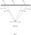
- FIG 1illustrates a prior art system showing two LEDs as may be used in a luminaire.
- LED 102 and LED 104may be of differing colors and, due to the different optical properties and construction of the LED dies, produce light beams 106 and 110 that differ in beam spread.
- the differing beam spreadsmean that the light beams from LEDs 102 and 104 will impinge on an illuminated object 118 in such a way that areas 114 and 116 of the object are illuminated by a single LED only rather than the desired mix of both. This results in areas 114 and 116 being colored differently from the central mixed area and appearing as colored fringes. Only two (2) LEDs are illustrated in Figure 1 for clarity and simplicity. It should be appreciated that the same problem exists with systems incorporating more than two colors of LED.
- FIG. 2illustrates a typical multiparameter automated LED luminaire system 10.
- These systemscommonly include a plurality of multiparameter automated luminaires 12 which typically each contain on-board an array of LEDs, and electric motors coupled to mechanical drives systems and control electronics (not shown).
- each luminaireis connected is series or in parallel to data link 14 to one or more control desk(s) 15.
- the luminaire system 10is typically controlled by an operator through the control desk 15. Consequently, to affect this control, both the control desk 10 and the individual luminaires typically include electronic circuitry as part of the electromechanical control system for controlling the automated lighting parameters.
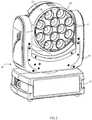
- FIG. 3illustrates an automated luminaire embodiment of the invention.
- Luminaire 20contains multiple LED modules each of which is fitted with primary optics 24, central spill light blocker 26, and small louver masks 27.
- Louver masks 27may have different heights and width. By changing the louver masks 27 to ones with different heights of louver array the user may control the beam angle, stray light and color fringing of the luminaire in addition to that control provided by the central spill light blocker 26 described in greater detail below. Louver mask array 27 may further provide mechanical protection and dust exclusion for the LED modules.
- FIG. 4illustrates a detailed view of a component of an embodiment of the invention.
- Primary optics 24, one for each LED array,are supported by frame 28.
- Each primary optic 24is fitted with a central spill light blocker 26.
- Central spill light blocker 26is an opaque mask applied over the central region of primary optic 24.
- Central spill light blocker 26may be silk screened ink, or a physical disc made of paper, plastic, molded plastic, metal or any other material, adhered to the center of the primary optic 24.
- Central spill light blocker 26may be a thin component as shown in the figures, or may have a tangible thickness or height, where the thickness provides additional spill light masking.
- Primary optic 24is most commonly a TIR (Total Internal Reflection) optical lens designed to collimate the output of the associated LED array and produce a narrow output beam. Such TIR optics tend to produce spill light outside of the desired output beam, much of which passes through the central portion of the output face of the optic. By blocking that central portion with central spill light blocker 26, much of this spill light may be removed from the output beam, leaving only the narrow beam desired. The central spill light blocker 26 will reduce the overall efficiency of the optical system, but ensures that more of the light produced is within the desired beam angle.
- the opaque maskmay be primarily absorptive. In alternative embodiments the mask may be reflective. If reflective the mask may be planar however, in some preferred embodiments the reflective mask would be non-planar.
- Each primary optic 24is fitted with a key peg 30 which engages in a corresponding key slot 34 at the side of the mounting hole 32 in plate 28.
- Figure 5illustrates operation of the various optical elements of the luminaire as they relate to a single LED module of an embodiment of the invention.
- the light output from an LED module 40which may contain multiple LEDs of the same or differing colors, enters primary optic 24 via a receiving orifice 42.
- Primary optic 24provides beam collimation and may be a reflector or a lens utilizing total internal refection (TIR). As illustrated in this embodiment, the primary optic 24 is generally parabolic in shape and the receiving orifice 42 is generally located proximate to the focus of the parabolic shape.
- louver mask 27is part of the system which provides this function.
- primary optic 24will tend to also produce stray light rays that are outside the desired output beam angle. Such rays, for example 52 in Figure 5 , tend to be emitted through the central portion of the output face of primary optic 24. Central spill light blocker 26 is placed over this central region so as to block many of these stray light rays and prevent them from reaching the output beam. Light rays that are within the desired beam angle, for example 50 in Figure 5 , miss the central spill light blocker 26 and continue through the optical system.
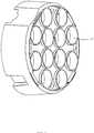
- FIG. 6illustrates an array of small louver masks of an embodiment of the invention.
- Each louver mask 27aligns with its associated LED array and primary optic.
- the array of small louver masksis manufactured as a single component, it may easily be replaced in order to provide different height louver masks for all LEDs simultaneously.
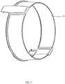
- FIG. 7illustrates a top-hat module of an embodiment of the invention.
- the top-hat module 29provides a further optional, level of spill light control, in addition to the small louvers and central spill light blockers.
- Figure 8illustrates a cut-away view of an assembled embodiment of the invention as fitted to an automated luminaire 100 of Figure 1 .
- individual LED module(s) 40is/are paired with primary optic(s) 24, which in turn is/are fitted with individual central spill light blockers 26, and is/are paired with small louver array mask 27.
- Optional top-hat module 29is fitted to the front of the system.
- the LED modules 40are configured in an array.
- each LED module 40may comprise a single LED die of a single color or a group of LED dies of the same or differing colors.
- LED 40may comprise one each of a Red, Green, Blue and White LED die.
- LED 40may comprise LED chip or package while in yet further embodiments LED 40 may comprise multiple LED chips or packages either under a single primary optic or each package with its own primary optic.
- these LED die(s)may be paired with optical lens element(s) as part of the LED module.
- the LED modules 40 shownare illustrated as individual pieces, in various embodiments these modules 40 may be set out in an array of multiple modules as one piece or multiple pieces.
- the primary optics 24are illustrated as one piece per LED module. In other embodiments the primary optics may be configured in an array of multiple primary optics to be paired with an array of multiple LED modules.
- every small louver mask 27 on each module in the luminaireis identical but in further embodiments the louver masks 27 may differ within a single module or between different modules across the luminaire.
- the height of louver mask array 27may be varied to effect different controlled beam angles for the emitted light. Such combinations of differing optical elements and louver array height may be advantageously chosen so as to allow fine control of the beam shape and quality.
- the louver mask arraysreduce color fringing or halation and control the beam angle to provide the lighting designer with a well controlled and defined beam of a single homogeneous color.
- louver masks 27will alter the constrained beam angle of the output beam.
- a taller louverwill produce a narrower beam and a shorter louver will produce a wider beam.
- the louver masks 27may be of fixed height or may be adjustable. Louver masks 27 may advantageously be non-reflective so as to avoid spill light, this may be achieved by painting or coating the louver mask with matte black paint, anodizing or other coating as known in the art.
- louver masks 27may be translucent or transparent to produce a glow effect within the face of the luminaire.
- LED module 40may contain LEDs of a single color and type or of multiple colors.
- the inventionis not limited by the number, colors, or types of LEDs used and is applicable with any layout of any number of any type and any color of LEDs or OLEDs.
- FIG 9illustrates an automated luminaire embodiment of the invention when fitted with the optional top-hat module.
- Luminaire 20contains multiple LED modules each of which is fitted with primary optics 24, central spill light blocker 26, and small louver masks 27.
- This embodimentis also fitted with optional top-hat module 29.
- the top-hat module 29provides a further optional, level of spill light control, in addition to the small louvers and central spill light blockers.
Landscapes
- Engineering & Computer Science (AREA)
- General Engineering & Computer Science (AREA)
- Physics & Mathematics (AREA)
- General Physics & Mathematics (AREA)
- Optics & Photonics (AREA)
- Non-Portable Lighting Devices Or Systems Thereof (AREA)
Description
- The present invention generally relates to a method for controlling the light output from an array of LEDs when used in a light beam producing luminaire, specifically to a method relating to preventing spill light and for controlling the beam angle of the array.
- High power LEDs are commonly used in luminaires for example in the architectural lighting industry in stores, offices and businesses as well as in the entertainment industry in theatres, television studios, concerts, theme parks, night clubs and other venues. These LEDs are also being utilized in automated lighting luminaires with automated and remotely controllable functionality. For color control it is common to use an array of LEDs of different colors. For example a common configuration is to use a mix of Red, Green and Blue LEDs. This configuration allows the user to create the color they desire by mixing appropriate levels of the three colors. For example illuminating the Red and Green LEDs while leaving the Blue extinguished will result in an output that appears Yellow. Similarly Red and Blue will result in Magenta, and Blue and Green will result in Cyan. By judicious control of these three controls the user may achieve any color they desire. More than three colors may also be used and it is well known to add an Amber or White LED to the Red, Green and Blue to enhance the color mixing and improve the gamut of colors available.
- The differently colored LEDs may be arranged in an array in the luminaire where there is physical separation between each LED, and this separation, coupled with differences in die size and placement for each color, may affect the spread of the individual colors and results in objectionable spill light and color fringing of the combined mixed color output beam. It is common to use a lens or other optical device in front of each LED to control the beam shape and angle of the output beam; however these optical devices commonly have differing effect for different colors and color fringing or other aberrations may be visible in the output beam. It would be advantageous to have a system where stray light and aberrations are well controlled.
WO 2011/131198 A1 discloses a moving head light fixture according to the preamble of claim 1, with a base, a yoke rotatably connected to the base, and a head rotatably connected to the yoke. The head includes a number of light sources and a number of light collecting means arranged in the head. The light collecting means being total internal reflection lenses, mixers or other lenses collect and convert light of the light sources into a number of light source beams. The beams are emitted from the head and pass a diffusion cover, wherein the diffusion cover diffuses at least part of the light generated by the light sources. The diffusion cover protrudes from the head and can also include non-diffusing regions in the form of apertures where the light pass without being diffused surrounded by diffusing regions where the light passing the diffusion cover is diffused.- There is a need for a beam control system for an LED array based luminaire which provides improvements in spill light reduction and beam angle control.
- The invention is defined in independent claim 1. Particular embodiments are set out in the dependnet claims.
- In particlar, an automated luminaire is disclosed. The luminaire comprises an array of LEDs; a plurality of primary optics which are arrayed to aligning with the array of LEDs; and a plurality of louvers that align with the plurality of primary optics. Each of the plurality of primary optics includes a central spill light blocker configured in the center of the primary optic, whereby undesirable light spill is limited and a more constrained light beam is produced.
- For a more complete understanding of the present invention and the advantages thereof, reference is now made to the following description taken in conjunction with the accompanying drawings in which like reference numerals indicate like features and wherein:
FIGURE 1 illustrates a prior art system;FIGURE 2 illustrates a typical automated lighting system;FIGURE 3 illustrates an embodiment of the invention as fitted to an automated luminaire;FIGURE 4 illustrates a detailed view of an embodiment of the invention;FIGURE 5 illustrates the optical design of an embodiment of the invention;FIGURE 6 illustrates a small louver mask of an embodiment of the invention;FIGURE 7 illustrates a top-hat module of an embodiment of the invention;FIGURE 8 illustrates an exploded diagram of an embodiment of the invention, and;FIGURE 9 illustrates an embodiment of the invention as fitted to an automated luminaire- Preferred embodiments of the present invention are illustrated in theFIGUREs, like numerals being used to refer to like and corresponding parts of the various drawings.
- The present invention generally relates to a method for controlling the light output from an array of LEDs when used in a light beam producing luminaire, specifically to a method relating to preventing spill light and for controlling the beam angle of the array.
Figure 1 illustrates a prior art system showing two LEDs as may be used in a luminaire.LED 102 andLED 104 may be of differing colors and, due to the different optical properties and construction of the LED dies, producelight beams LEDs illuminated object 118 in such a way thatareas areas Figure 1 for clarity and simplicity. It should be appreciated that the same problem exists with systems incorporating more than two colors of LED.Figure 2 illustrates a typical multiparameter automatedLED luminaire system 10. These systems commonly include a plurality of multiparameterautomated luminaires 12 which typically each contain on-board an array of LEDs, and electric motors coupled to mechanical drives systems and control electronics (not shown). In addition to being connected to mains power either directly or through a power distribution system (not shown), each luminaire is connected is series or in parallel todata link 14 to one or more control desk(s)15. Theluminaire system 10 is typically controlled by an operator through the control desk15. Consequently, to affect this control, both thecontrol desk 10 and the individual luminaires typically include electronic circuitry as part of the electromechanical control system for controlling the automated lighting parameters.Figure 3 illustrates an automated luminaire embodiment of the invention. Luminaire20 contains multiple LED modules each of which is fitted withprimary optics 24, centralspill light blocker 26, andsmall louver masks 27.Louver masks 27 may have different heights and width. By changing thelouver masks 27 to ones with different heights of louver array the user may control the beam angle, stray light and color fringing of the luminaire in addition to that control provided by the centralspill light blocker 26 described in greater detail below. Louvermask array 27 may further provide mechanical protection and dust exclusion for the LED modules.Figure 4 illustrates a detailed view of a component of an embodiment of the invention.Primary optics 24, one for each LED array, are supported byframe 28. Eachprimary optic 24 is fitted with a centralspill light blocker 26. Centralspill light blocker 26 is an opaque mask applied over the central region of primary optic24. Centralspill light blocker 26 may be silk screened ink, or a physical disc made of paper, plastic, molded plastic, metal or any other material, adhered to the center of theprimary optic 24. Centralspill light blocker 26 may be a thin component as shown in the figures, or may have a tangible thickness or height, where the thickness provides additional spill light masking.Primary optic 24 is most commonly a TIR (Total Internal Reflection) optical lens designed to collimate the output of the associated LED array and produce a narrow output beam. Such TIR optics tend to produce spill light outside of the desired output beam, much of which passes through the central portion of the output face of the optic. By blocking that central portion with centralspill light blocker 26, much of this spill light may be removed from the output beam, leaving only the narrow beam desired. The centralspill light blocker 26 will reduce the overall efficiency of the optical system, but ensures that more of the light produced is within the desired beam angle. The opaque mask may be primarily absorptive. In alternative embodiments the mask may be reflective. If reflective the mask may be planar however, in some preferred embodiments the reflective mask would be non-planar. Eachprimary optic 24 is fitted with a key peg30 which engages in a correspondingkey slot 34 at the side of the mountinghole 32 inplate 28.Figure 5 illustrates operation of the various optical elements of the luminaire as they relate to a single LED module of an embodiment of the invention. The light output from an LED module40, which may contain multiple LEDs of the same or differing colors, entersprimary optic 24 via a receiving orifice42.Primary optic 24 provides beam collimation and may be a reflector or a lens utilizing total internal refection (TIR). As illustrated in this embodiment, theprimary optic 24 is generally parabolic in shape and the receiving orifice42 is generally located proximate to the focus of the parabolic shape. After passing through and being constrained byprimary optic 24 the light beam is further constrained by a set of louver masks as disclosed and described inUS Patent Application 2010/0103663 .It is advantageous in such systems to provide a louver mask system adjacent to the light source such that differing colors of LEDs are constrained to similar output areas and thus minimize color fringing and spill light.Small louver mask 27 is part of the system which provides this function.- Because LED array40 is not a true point source,
primary optic 24 will tend to also produce stray light rays that are outside the desired output beam angle. Such rays, for example52 inFigure 5 , tend to be emitted through the central portion of the output face ofprimary optic 24. Centralspill light blocker 26 is placed over this central region so as to block many of these stray light rays and prevent them from reaching the output beam. Light rays that are within the desired beam angle, for example50 inFigure 5 , miss the centralspill light blocker 26 and continue through the optical system. Figure 6 illustrates an array of small louver masks of an embodiment of the invention. Eachlouver mask 27 aligns with its associated LED array and primary optic. As the array of small louver masks is manufactured as a single component, it may easily be replaced in order to provide different height louver masks for all LEDs simultaneously.Figure 7 illustrates a top-hat module of an embodiment of the invention. The top-hat module29 provides a further optional, level of spill light control, in addition to the small louvers and central spill light blockers.Figure 8 illustrates a cut-away view of an assembled embodiment of the invention as fitted to an automated luminaire100 ofFigure 1 . From left to right individual LED module(s)40 is/are paired with primary optic(s)24, which in turn is/are fitted with individual centralspill light blockers 26, and is/are paired with smalllouver array mask 27. Optional top-hat module 29 is fitted to the front of the system. In the embodiment illustrated inFigure 8 , the LED modules40 are configured in an array.- In various embodiments, each LED module40 may comprise a single LED die of a single color or a group of LED dies of the same or differing colors. For example in one embodiment LED40 may comprise one each of a Red, Green, Blue and White LED die. In further embodiments LED 40 may comprise LED chip or package while in yet further embodiments LED 40 may comprise multiple LED chips or packages either under a single primary optic or each package with its own primary optic. In some embodiments these LED die(s) may be paired with optical lens element(s) as part of the LED module. Though the LED modules40 shown are illustrated as individual pieces, in various embodiments these modules40 may be set out in an array of multiple modules as one piece or multiple pieces. Similarly the
primary optics 24 are illustrated as one piece per LED module. In other embodiments the primary optics may be configured in an array of multiple primary optics to be paired with an array of multiple LED modules. - In one embodiment of the invention every
small louver mask 27 on each module in the luminaire is identical but in further embodiments the louver masks27 may differ within a single module or between different modules across the luminaire. In yet further embodiments the height oflouver mask array 27 may be varied to effect different controlled beam angles for the emitted light. Such combinations of differing optical elements and louver array height may be advantageously chosen so as to allow fine control of the beam shape and quality. The louver mask arrays reduce color fringing or halation and control the beam angle to provide the lighting designer with a well controlled and defined beam of a single homogeneous color. - It can be seen that changing the heights of louver masks27 will alter the constrained beam angle of the output beam. A taller louver will produce a narrower beam and a shorter louver will produce a wider beam. The louver masks27 may be of fixed height or may be adjustable. Louver masks27 may advantageously be non-reflective so as to avoid spill light, this may be achieved by painting or coating the louver mask with matte black paint, anodizing or other coating as known in the art.
- In a further embodiment louver masks27 may be translucent or transparent to produce a glow effect within the face of the luminaire.
- LED module40 may contain LEDs of a single color and type or of multiple colors. The invention is not limited by the number, colors, or types of LEDs used and is applicable with any layout of any number of any type and any color of LEDs or OLEDs.
Figure 9 illustrates an automated luminaire embodiment of the invention when fitted with the optional top-hat module.Luminaire 20 contains multiple LED modules each of which is fitted withprimary optics 24, centralspill light blocker 26, and small louver masks27. This embodiment is also fitted with optional top-hat module29. The top-hat module29 provides a further optional, level of spill light control, in addition to the small louvers and central spill light blockers.- While the disclosure has been described with respect to a limited number of embodiments, those skilled in the art, having benefit of this disclosure, will appreciate that other embodiments may be devised which do not depart from the scope of the disclosure as disclosed herein.
Claims (11)
- An automated luminaire comprising:an array of LEDs (40);a plurality of primary optics (24) which are arrayed to aligning with the array of LEDs (40); anda plurality of louvers (27) that align with the plurality of primary optics (24)characterized in thateach of the plurality of primary optics (24) includes a central spill light blocker (26) configured in the center of the primary optic (24), whereby undesirable light spill is limited and a more constrained light beam is produced.
- An automated luminaire of claim 1, wherein the central spill light blocker (26) is light absorptive.
- An automated luminaire of claim 1, wherein the center spill light blocker (26) is light reflective.
- An automated luminaire of claim 3, wherein the center spill light blocker (26) is light planar.
- An automated luminaire of claim 3, wherein the center spill light blocker (26) is light non planar.
- An automated luminaire of any preceding claim, wherein each of the plurality of primary optics (24) is generally parabolic with a receiving orifice (42) proximate to the focus of the parabola.
- An automated luminaire of any preceding claim, wherein the primary optic (24) comprises a TIR optical lens.
- An automated luminaire of any preceding claim, wherein the plurality of louvers (27) aligned with the primary optics (24) are surrounded by a top-hat module (29) adapted to be fitted to the front of the automated luminaire (20).
- An automated luminaire of any preceding claim, wherein the plurality of louvers (27) is manufactured as a single replacement component.
- An automated luminaire of any preceding claim, wherein the plurality of louvers (27) is adapted to be adjustable in height.
- An automated luminaire of any preceding claim, wherein the plurality of louvers (27) individually aligns with individual primary optics.
Applications Claiming Priority (2)
| Application Number | Priority Date | Filing Date | Title |
|---|---|---|---|
| US201261612376P | 2012-03-18 | 2012-03-18 | |
| PCT/US2013/032851WO2013142437A1 (en) | 2012-03-18 | 2013-03-18 | Improved collimation system for an led luminaire |
Publications (2)
| Publication Number | Publication Date |
|---|---|
| EP2828573A1 EP2828573A1 (en) | 2015-01-28 |
| EP2828573B1true EP2828573B1 (en) | 2017-05-10 |
Family
ID=48325858
Family Applications (1)
| Application Number | Title | Priority Date | Filing Date |
|---|---|---|---|
| EP13721141.3AActiveEP2828573B1 (en) | 2012-03-18 | 2013-03-18 | Improved collimation system for an led luminaire |
Country Status (4)
| Country | Link |
|---|---|
| US (1) | US10161595B2 (en) |
| EP (1) | EP2828573B1 (en) |
| CN (1) | CN104302969B (en) |
| WO (1) | WO2013142437A1 (en) |
Families Citing this family (49)
| Publication number | Priority date | Publication date | Assignee | Title |
|---|---|---|---|---|
| USRE50468E1 (en) | 2008-09-05 | 2025-06-24 | Lutron Technology Company Llc | Intelligent illumination device |
| US8773336B2 (en) | 2008-09-05 | 2014-07-08 | Ketra, Inc. | Illumination devices and related systems and methods |
| US9276766B2 (en) | 2008-09-05 | 2016-03-01 | Ketra, Inc. | Display calibration systems and related methods |
| US9509525B2 (en) | 2008-09-05 | 2016-11-29 | Ketra, Inc. | Intelligent illumination device |
| US10210750B2 (en) | 2011-09-13 | 2019-02-19 | Lutron Electronics Co., Inc. | System and method of extending the communication range in a visible light communication system |
| USRE49454E1 (en) | 2010-09-30 | 2023-03-07 | Lutron Technology Company Llc | Lighting control system |
| US9386668B2 (en) | 2010-09-30 | 2016-07-05 | Ketra, Inc. | Lighting control system |
| DE102012213194A1 (en)* | 2012-07-26 | 2014-01-30 | Osram Gmbh | Radiation arrangement for providing electromagnetic radiation |
| USRE48955E1 (en) | 2013-08-20 | 2022-03-01 | Lutron Technology Company Llc | Interference-resistant compensation for illumination devices having multiple emitter modules |
| US9651632B1 (en) | 2013-08-20 | 2017-05-16 | Ketra, Inc. | Illumination device and temperature calibration method |
| USRE48956E1 (en) | 2013-08-20 | 2022-03-01 | Lutron Technology Company Llc | Interference-resistant compensation for illumination devices using multiple series of measurement intervals |
| US9345097B1 (en) | 2013-08-20 | 2016-05-17 | Ketra, Inc. | Interference-resistant compensation for illumination devices using multiple series of measurement intervals |
| US9332598B1 (en) | 2013-08-20 | 2016-05-03 | Ketra, Inc. | Interference-resistant compensation for illumination devices having multiple emitter modules |
| US9237620B1 (en) | 2013-08-20 | 2016-01-12 | Ketra, Inc. | Illumination device and temperature compensation method |
| US9155155B1 (en) | 2013-08-20 | 2015-10-06 | Ketra, Inc. | Overlapping measurement sequences for interference-resistant compensation in light emitting diode devices |
| US9247605B1 (en) | 2013-08-20 | 2016-01-26 | Ketra, Inc. | Interference-resistant compensation for illumination devices |
| US9578724B1 (en) | 2013-08-20 | 2017-02-21 | Ketra, Inc. | Illumination device and method for avoiding flicker |
| US9360174B2 (en) | 2013-12-05 | 2016-06-07 | Ketra, Inc. | Linear LED illumination device with improved color mixing |
| US9769899B2 (en) | 2014-06-25 | 2017-09-19 | Ketra, Inc. | Illumination device and age compensation method |
| US9736895B1 (en) | 2013-10-03 | 2017-08-15 | Ketra, Inc. | Color mixing optics for LED illumination device |
| DE102013222481A1 (en)* | 2013-11-06 | 2015-05-07 | Zumtobel Lighting Gmbh | Optical element for a lamp, as well as light |
| US9146028B2 (en) | 2013-12-05 | 2015-09-29 | Ketra, Inc. | Linear LED illumination device with improved rotational hinge |
| EP3875851A1 (en)* | 2013-12-05 | 2021-09-08 | Lutron Ketra, LLC | Linear led illumination device with improved color mixing |
| WO2015138483A2 (en)* | 2014-03-10 | 2015-09-17 | Robe Lighting, Inc. | Optical system for an led luminaire |
| US10408402B2 (en) | 2014-03-10 | 2019-09-10 | Robe Lighting S.R.O. | Optical system for a LED luminaire |
| RU2671285C2 (en)* | 2014-05-13 | 2018-10-30 | Коэлюкс С.Р.Л. | Source of light and lighting system, imitating sunlight |
| US9392663B2 (en) | 2014-06-25 | 2016-07-12 | Ketra, Inc. | Illumination device and method for controlling an illumination device over changes in drive current and temperature |
| US9557214B2 (en) | 2014-06-25 | 2017-01-31 | Ketra, Inc. | Illumination device and method for calibrating an illumination device over changes in temperature, drive current, and time |
| US10161786B2 (en) | 2014-06-25 | 2018-12-25 | Lutron Ketra, Llc | Emitter module for an LED illumination device |
| US9736903B2 (en) | 2014-06-25 | 2017-08-15 | Ketra, Inc. | Illumination device and method for calibrating and controlling an illumination device comprising a phosphor converted LED |
| US9510416B2 (en) | 2014-08-28 | 2016-11-29 | Ketra, Inc. | LED illumination device and method for accurately controlling the intensity and color point of the illumination device over time |
| US9392660B2 (en) | 2014-08-28 | 2016-07-12 | Ketra, Inc. | LED illumination device and calibration method for accurately characterizing the emission LEDs and photodetector(s) included within the LED illumination device |
| US9237612B1 (en) | 2015-01-26 | 2016-01-12 | Ketra, Inc. | Illumination device and method for determining a target lumens that can be safely produced by an illumination device at a present temperature |
| ES2628866T3 (en) | 2015-01-26 | 2017-08-04 | Schreder | Improvements in, or related to, lens groupings |
| US9485813B1 (en) | 2015-01-26 | 2016-11-01 | Ketra, Inc. | Illumination device and method for avoiding an over-power or over-current condition in a power converter |
| US9237623B1 (en) | 2015-01-26 | 2016-01-12 | Ketra, Inc. | Illumination device and method for determining a maximum lumens that can be safely produced by the illumination device to achieve a target chromaticity |
| DE202015106256U1 (en)* | 2015-11-18 | 2017-02-22 | Zumtobel Lighting Gmbh | Blendarme lighting technology |
| US10193018B2 (en)* | 2016-12-29 | 2019-01-29 | Intel Corporation | Compact low power head-mounted display with light emitting diodes that exhibit a desired beam angle |
| US10378733B1 (en)* | 2017-10-30 | 2019-08-13 | Race, LLC | Modular optical assembly and light emission system |
| US10801678B1 (en) | 2017-10-30 | 2020-10-13 | Race, LLC | Modular emitting device and light emission system |
| EP3767166B1 (en)* | 2018-03-16 | 2021-09-29 | Antares Iluminación, S.A.U. | Optical system |
| US11272599B1 (en) | 2018-06-22 | 2022-03-08 | Lutron Technology Company Llc | Calibration procedure for a light-emitting diode light source |
| WO2020030302A1 (en)* | 2018-08-10 | 2020-02-13 | Eaton Intelligent Power Limited | Integrated louvres for beam control in an led lighting device |
| FR3112219B1 (en)* | 2020-07-01 | 2022-07-15 | Ayrton | Optical assembly for a projector and projector comprising such an optical assembly |
| CN112254026B (en)* | 2020-09-16 | 2024-02-06 | 赛尔富电子有限公司 | Anti-dazzle lamp and illumination arrangement method adopting same |
| GB2599076B (en)* | 2020-09-08 | 2025-07-23 | Iq Structures Sro | Modular luminaires |
| GB2599354A (en)* | 2020-09-08 | 2022-04-06 | Iq Structures Sro | Optical cells for modular luminaires |
| US11118758B1 (en)* | 2020-11-03 | 2021-09-14 | Elemental LED, Inc. | Louvered optics for linear lighting |
| EP4075054B1 (en)* | 2021-04-15 | 2023-11-01 | Smart Electric Works Co.,Ltd. | Lampshade module capable of replacing optical projection elements |
Family Cites Families (48)
| Publication number | Priority date | Publication date | Assignee | Title |
|---|---|---|---|---|
| JPH08321918A (en)* | 1995-03-22 | 1996-12-03 | Canon Inc | Light guide body, illumination device having the light guide body, and information processing apparatus having the illumination device |
| DE19531295A1 (en)* | 1995-08-25 | 1997-02-27 | Reitter & Schefenacker Gmbh | Optic body for at least one LED |
| US6814470B2 (en)* | 2000-05-08 | 2004-11-09 | Farlight Llc | Highly efficient LED lamp |
| ITMI20030112A1 (en)* | 2003-01-24 | 2004-07-25 | Fraen Corp Srl | MULTIPLE OPTICAL ELEMENT FOR A LED LIGHTING DEVICE AND LED LIGHTING DEVICE INCLUDING SUCH OPTICAL ELEMENT. |
| US7553051B2 (en)* | 2004-03-18 | 2009-06-30 | Brasscorp Limited | LED work light |
| AU2005240186B2 (en)* | 2004-05-05 | 2011-02-03 | Rensselaer Polytechnic Institute | High efficiency light source using solid-state emitter and down-conversion material |
| KR101214934B1 (en)* | 2005-01-27 | 2012-12-24 | 삼성디스플레이 주식회사 | Optical lens and optical module having the optical lens and back light assembly having the optical module, and the display apparatus having the back light assembly |
| TWI303701B (en)* | 2004-11-30 | 2008-12-01 | Mirai Co Ltd | Illumination unit and illumination apparatus |
| DE102005061431B4 (en)* | 2005-02-03 | 2020-01-02 | Samsung Electronics Co., Ltd. | Side emission type LED unit |
| ITMI20050122U1 (en)* | 2005-04-08 | 2006-10-09 | Guzzini Illuminazione Srl I | ANTI-BLASTING DEVICE FOR LED LIGHT SOURCES |
| EP2757401A1 (en)* | 2005-04-26 | 2014-07-23 | LG Innotek Co., Ltd. | Optical lens, light emitting device package using the optical lens, and backlight unit |
| US20080047605A1 (en)* | 2005-07-28 | 2008-02-28 | Regents Of The University Of California | Multi-junction solar cells with a homogenizer system and coupled non-imaging light concentrator |
| EP1920285A4 (en)* | 2005-07-28 | 2010-11-03 | Light Prescriptions Innovators | OPEN-FREE LENTICULAR OPTICAL ELEMENTS AND THEIR APPLICATION TO CAPACITORS AND PROJECTORS |
| US8631787B2 (en)* | 2005-07-28 | 2014-01-21 | Light Prescriptions Innovators, Llc | Multi-junction solar cells with a homogenizer system and coupled non-imaging light concentrator |
| JP4993434B2 (en)* | 2005-11-18 | 2012-08-08 | スタンレー電気株式会社 | White LED lighting device |
| US7461960B2 (en)* | 2006-05-05 | 2008-12-09 | Zweibruder Optoelectronics | LED illumination module |
| US7918583B2 (en)* | 2006-08-16 | 2011-04-05 | Rpc Photonics, Inc. | Illumination devices |
| CN101150160A (en)* | 2006-09-22 | 2008-03-26 | 鸿富锦精密工业(深圳)有限公司 | Light-emitting diode and its manufacturing method |
| TWM310984U (en)* | 2006-11-28 | 2007-05-01 | Primo Lite Co Ltd | Lamp structure of light emitting diode |
| US20090231739A1 (en)* | 2007-05-07 | 2009-09-17 | The Regents Of The University Of California A California Corporation | Matrix formulation of kohler integrating system and coupled non-imaging light concentrator |
| JP4970136B2 (en)* | 2007-05-17 | 2012-07-04 | 株式会社小糸製作所 | Vehicle headlamp lamp unit |
| JP2010534411A (en)* | 2007-07-25 | 2010-11-04 | コーニンクレッカ フィリップス エレクトロニクス エヌ ヴィ | Color conversion element and light output device capable of color control |
| WO2009033051A1 (en)* | 2007-09-07 | 2009-03-12 | Philips Solid-State Lighting Solutions | Methods and apparatus for providing led-based spotlight illumination in stage lighting applications |
| EP2201292A4 (en)* | 2007-10-25 | 2012-11-14 | Lsi Industries Inc | Reflector |
| US7654690B2 (en)* | 2008-01-13 | 2010-02-02 | Tang Shih Chuan | Lampshade for a light-emitting diode (LED) lamp |
| US20100225639A1 (en)* | 2008-03-11 | 2010-09-09 | Robe Lighting S.R.O. | Array of led array luminaires |
| IT1391091B1 (en)* | 2008-07-15 | 2011-11-18 | Fraen Corp Srl | LIGHTING DEVICE WITH ADJUSTABLE LIGHTING, IN PARTICULAR FOR AN ELECTRIC TORCH |
| CA2676315A1 (en)* | 2008-08-22 | 2010-02-22 | Virginia Optoelectronics, Inc. | Led lamp assembly |
| EP2342491A2 (en)* | 2008-10-20 | 2011-07-13 | Robe Lighting Inc. | Led array beam control luminaires |
| US20100296296A1 (en)* | 2008-10-27 | 2010-11-25 | National Central University | High contrast light pattern projection mechanism |
| US8764238B2 (en) | 2008-11-06 | 2014-07-01 | Innovations In Optics, Inc. | Light emitting diode emergency lighting module |
| US7580192B1 (en)* | 2008-12-23 | 2009-08-25 | Smart Champ Enterprise Limited | Collimation lens system for LED |
| US8083364B2 (en)* | 2008-12-29 | 2011-12-27 | Osram Sylvania Inc. | Remote phosphor LED illumination system |
| US8721101B2 (en)* | 2009-09-21 | 2014-05-13 | Koninklijke Philips N.V. | Light emitting device comprising a light guide plate with reflective shielding with glare reduction |
| KR101028304B1 (en)* | 2009-10-15 | 2011-04-11 | 엘지이노텍 주식회사 | Light emitting apparatus |
| EP2536975B1 (en)* | 2010-02-16 | 2015-04-29 | Martin Professional ApS | Belt tensioning means integrated into illumination device shell part |
| GB2479142A (en)* | 2010-03-30 | 2011-10-05 | Optovate Ltd | Illumination Apparatus |
| DK177579B1 (en)* | 2010-04-23 | 2013-10-28 | Martin Professional As | Led light fixture with background lighting |
| US8950895B2 (en)* | 2010-04-23 | 2015-02-10 | Martin Professional Aps | Moving head light fixture with protruding diffuser cover and multiple light sources |
| US8794792B1 (en)* | 2010-09-09 | 2014-08-05 | Cooper Technologies Company | Optical spill light reducer for luminaires |
| CN102588762A (en)* | 2011-01-06 | 2012-07-18 | 隆达电子股份有限公司 | LED Cup Light |
| DE102011008474B4 (en)* | 2011-01-13 | 2012-08-09 | Dräger Medical GmbH | Operating light with LED orientation by means of positive locking |
| US8272759B2 (en)* | 2011-01-18 | 2012-09-25 | Dbm Reflex Of Taiwan Co., Ltd. | Light-emitting diode lampshade |
| US9470882B2 (en)* | 2011-04-25 | 2016-10-18 | Cree, Inc. | Optical arrangement for a solid-state lamp |
| US8485691B2 (en)* | 2011-05-13 | 2013-07-16 | Lumenpulse Lighting, Inc. | High powered light emitting diode lighting unit |
| US9347642B2 (en)* | 2011-09-07 | 2016-05-24 | Terralux, Inc. | Faceted optics for illumination devices |
| US20130208478A1 (en)* | 2012-02-14 | 2013-08-15 | Xiao Pie Tao | Adaptor for converting laser devices to lighting |
| EP2636943A1 (en)* | 2012-03-06 | 2013-09-11 | Hui-Peng Tseng | LED lamp set for enhancing illumination and eliminating ghost images |
- 2013
- 2013-03-18EPEP13721141.3Apatent/EP2828573B1/enactiveActive
- 2013-03-18CNCN201380025137.6Apatent/CN104302969B/enactiveActive
- 2013-03-18WOPCT/US2013/032851patent/WO2013142437A1/enactiveApplication Filing
- 2013-03-18USUS14/386,317patent/US10161595B2/enactiveActive
Also Published As
| Publication number | Publication date |
|---|---|
| US20150316229A1 (en) | 2015-11-05 |
| US10161595B2 (en) | 2018-12-25 |
| EP2828573A1 (en) | 2015-01-28 |
| CN104302969B (en) | 2018-05-18 |
| CN104302969A (en) | 2015-01-21 |
| WO2013142437A1 (en) | 2013-09-26 |
Similar Documents
| Publication | Publication Date | Title |
|---|---|---|
| EP2828573B1 (en) | Improved collimation system for an led luminaire | |
| US10072801B2 (en) | Collimation and homogenization system for an LED luminaire | |
| US10520175B2 (en) | Collimation and homogenization system for an LED luminaire | |
| EP2177816B1 (en) | A ligth collection system for an led luminaire | |
| EP3002505B1 (en) | Array-based lighting systems and methods of manufacturing | |
| EP3715709A2 (en) | Led light engine with integrated color system | |
| US10563839B2 (en) | System and method for preventing light spill | |
| EP2643632B1 (en) | Improved beam control for an led luminaire | |
| EP2841846B1 (en) | Illumination systems and methods | |
| CN110325787A (en) | Lamps and lanterns with light guide | |
| JP2006524909A (en) | light source | |
| EP3227601B1 (en) | Collimation and homogenization system for an led luminaire | |
| US10386030B2 (en) | Light fixture, preferably for stage | |
| EP3052981A2 (en) | Multiple color homogenization system for an led luminaire | |
| US10408402B2 (en) | Optical system for a LED luminaire | |
| RU2597792C2 (en) | Luminaire emitting light of different colours | |
| EP2810121B1 (en) | An improved light collimation system | |
| US20180313521A1 (en) | System and method for controlling output in a led luminaire | |
| CN109312902B (en) | Dyeing light illuminating device with special effect function | |
| KR101837431B1 (en) | Led lighting device for improving quality of lighting | |
| WO2011117815A1 (en) | Spot illumination system with improved light mixing | |
| WO2017165685A1 (en) | Optical system for an led luminaire |
Legal Events
| Date | Code | Title | Description |
|---|---|---|---|
| PUAI | Public reference made under article 153(3) epc to a published international application that has entered the european phase | Free format text:ORIGINAL CODE: 0009012 | |
| 17P | Request for examination filed | Effective date:20141020 | |
| AK | Designated contracting states | Kind code of ref document:A1 Designated state(s):AL AT BE BG CH CY CZ DE DK EE ES FI FR GB GR HR HU IE IS IT LI LT LU LV MC MK MT NL NO PL PT RO RS SE SI SK SM TR | |
| AX | Request for extension of the european patent | Extension state:BA ME | |
| DAX | Request for extension of the european patent (deleted) | ||
| RIN1 | Information on inventor provided before grant (corrected) | Inventor name:JURIK, PAVEL Inventor name:VALCHAR, JOSEF | |
| GRAP | Despatch of communication of intention to grant a patent | Free format text:ORIGINAL CODE: EPIDOSNIGR1 | |
| RIC1 | Information provided on ipc code assigned before grant | Ipc:F21W 131/406 20060101ALN20160502BHEP Ipc:F21Y 105/10 20160101ALN20160502BHEP Ipc:F21V 5/04 20060101ALI20160502BHEP Ipc:F21V 11/06 20060101ALI20160502BHEP Ipc:F21Y 113/10 20160101ALN20160502BHEP Ipc:G02B 19/00 20060101ALI20160502BHEP Ipc:F21V 5/00 20150101AFI20160502BHEP Ipc:F21Y 115/10 20160101ALN20160502BHEP Ipc:F21V 17/00 20060101ALN20160502BHEP Ipc:F21V 7/00 20060101ALI20160502BHEP Ipc:F21V 21/30 20060101ALN20160502BHEP | |
| INTG | Intention to grant announced | Effective date:20160606 | |
| GRAS | Grant fee paid | Free format text:ORIGINAL CODE: EPIDOSNIGR3 | |
| GRAA | (expected) grant | Free format text:ORIGINAL CODE: 0009210 | |
| AK | Designated contracting states | Kind code of ref document:B1 Designated state(s):AL AT BE BG CH CY CZ DE DK EE ES FI FR GB GR HR HU IE IS IT LI LT LU LV MC MK MT NL NO PL PT RO RS SE SI SK SM TR | |
| REG | Reference to a national code | Ref country code:GB Ref legal event code:FG4D | |
| REG | Reference to a national code | Ref country code:AT Ref legal event code:REF Ref document number:892742 Country of ref document:AT Kind code of ref document:T Effective date:20170515 Ref country code:CH Ref legal event code:EP | |
| REG | Reference to a national code | Ref country code:IE Ref legal event code:FG4D | |
| REG | Reference to a national code | Ref country code:DE Ref legal event code:R096 Ref document number:602013020942 Country of ref document:DE | |
| REG | Reference to a national code | Ref country code:NL Ref legal event code:MP Effective date:20170510 | |
| REG | Reference to a national code | Ref country code:LT Ref legal event code:MG4D | |
| REG | Reference to a national code | Ref country code:AT Ref legal event code:MK05 Ref document number:892742 Country of ref document:AT Kind code of ref document:T Effective date:20170510 | |
| PG25 | Lapsed in a contracting state [announced via postgrant information from national office to epo] | Ref country code:ES Free format text:LAPSE BECAUSE OF FAILURE TO SUBMIT A TRANSLATION OF THE DESCRIPTION OR TO PAY THE FEE WITHIN THE PRESCRIBED TIME-LIMIT Effective date:20170510 Ref country code:LT Free format text:LAPSE BECAUSE OF FAILURE TO SUBMIT A TRANSLATION OF THE DESCRIPTION OR TO PAY THE FEE WITHIN THE PRESCRIBED TIME-LIMIT Effective date:20170510 Ref country code:FI Free format text:LAPSE BECAUSE OF FAILURE TO SUBMIT A TRANSLATION OF THE DESCRIPTION OR TO PAY THE FEE WITHIN THE PRESCRIBED TIME-LIMIT Effective date:20170510 Ref country code:NO Free format text:LAPSE BECAUSE OF FAILURE TO SUBMIT A TRANSLATION OF THE DESCRIPTION OR TO PAY THE FEE WITHIN THE PRESCRIBED TIME-LIMIT Effective date:20170810 Ref country code:GR Free format text:LAPSE BECAUSE OF FAILURE TO SUBMIT A TRANSLATION OF THE DESCRIPTION OR TO PAY THE FEE WITHIN THE PRESCRIBED TIME-LIMIT Effective date:20170811 Ref country code:HR Free format text:LAPSE BECAUSE OF FAILURE TO SUBMIT A TRANSLATION OF THE DESCRIPTION OR TO PAY THE FEE WITHIN THE PRESCRIBED TIME-LIMIT Effective date:20170510 Ref country code:AT Free format text:LAPSE BECAUSE OF FAILURE TO SUBMIT A TRANSLATION OF THE DESCRIPTION OR TO PAY THE FEE WITHIN THE PRESCRIBED TIME-LIMIT Effective date:20170510 | |
| PG25 | Lapsed in a contracting state [announced via postgrant information from national office to epo] | Ref country code:IS Free format text:LAPSE BECAUSE OF FAILURE TO SUBMIT A TRANSLATION OF THE DESCRIPTION OR TO PAY THE FEE WITHIN THE PRESCRIBED TIME-LIMIT Effective date:20170910 Ref country code:LV Free format text:LAPSE BECAUSE OF FAILURE TO SUBMIT A TRANSLATION OF THE DESCRIPTION OR TO PAY THE FEE WITHIN THE PRESCRIBED TIME-LIMIT Effective date:20170510 Ref country code:RS Free format text:LAPSE BECAUSE OF FAILURE TO SUBMIT A TRANSLATION OF THE DESCRIPTION OR TO PAY THE FEE WITHIN THE PRESCRIBED TIME-LIMIT Effective date:20170510 Ref country code:BG Free format text:LAPSE BECAUSE OF FAILURE TO SUBMIT A TRANSLATION OF THE DESCRIPTION OR TO PAY THE FEE WITHIN THE PRESCRIBED TIME-LIMIT Effective date:20170810 Ref country code:SE Free format text:LAPSE BECAUSE OF FAILURE TO SUBMIT A TRANSLATION OF THE DESCRIPTION OR TO PAY THE FEE WITHIN THE PRESCRIBED TIME-LIMIT Effective date:20170510 Ref country code:PL Free format text:LAPSE BECAUSE OF FAILURE TO SUBMIT A TRANSLATION OF THE DESCRIPTION OR TO PAY THE FEE WITHIN THE PRESCRIBED TIME-LIMIT Effective date:20170510 Ref country code:NL Free format text:LAPSE BECAUSE OF FAILURE TO SUBMIT A TRANSLATION OF THE DESCRIPTION OR TO PAY THE FEE WITHIN THE PRESCRIBED TIME-LIMIT Effective date:20170510 | |
| PG25 | Lapsed in a contracting state [announced via postgrant information from national office to epo] | Ref country code:CZ Free format text:LAPSE BECAUSE OF FAILURE TO SUBMIT A TRANSLATION OF THE DESCRIPTION OR TO PAY THE FEE WITHIN THE PRESCRIBED TIME-LIMIT Effective date:20170510 Ref country code:SK Free format text:LAPSE BECAUSE OF FAILURE TO SUBMIT A TRANSLATION OF THE DESCRIPTION OR TO PAY THE FEE WITHIN THE PRESCRIBED TIME-LIMIT Effective date:20170510 Ref country code:DK Free format text:LAPSE BECAUSE OF FAILURE TO SUBMIT A TRANSLATION OF THE DESCRIPTION OR TO PAY THE FEE WITHIN THE PRESCRIBED TIME-LIMIT Effective date:20170510 Ref country code:RO Free format text:LAPSE BECAUSE OF FAILURE TO SUBMIT A TRANSLATION OF THE DESCRIPTION OR TO PAY THE FEE WITHIN THE PRESCRIBED TIME-LIMIT Effective date:20170510 Ref country code:EE Free format text:LAPSE BECAUSE OF FAILURE TO SUBMIT A TRANSLATION OF THE DESCRIPTION OR TO PAY THE FEE WITHIN THE PRESCRIBED TIME-LIMIT Effective date:20170510 | |
| REG | Reference to a national code | Ref country code:DE Ref legal event code:R097 Ref document number:602013020942 Country of ref document:DE | |
| PG25 | Lapsed in a contracting state [announced via postgrant information from national office to epo] | Ref country code:IT Free format text:LAPSE BECAUSE OF FAILURE TO SUBMIT A TRANSLATION OF THE DESCRIPTION OR TO PAY THE FEE WITHIN THE PRESCRIBED TIME-LIMIT Effective date:20170510 Ref country code:SM Free format text:LAPSE BECAUSE OF FAILURE TO SUBMIT A TRANSLATION OF THE DESCRIPTION OR TO PAY THE FEE WITHIN THE PRESCRIBED TIME-LIMIT Effective date:20170510 | |
| PLBE | No opposition filed within time limit | Free format text:ORIGINAL CODE: 0009261 | |
| STAA | Information on the status of an ep patent application or granted ep patent | Free format text:STATUS: NO OPPOSITION FILED WITHIN TIME LIMIT | |
| REG | Reference to a national code | Ref country code:DE Ref legal event code:R082 Ref document number:602013020942 Country of ref document:DE | |
| 26N | No opposition filed | Effective date:20180213 | |
| PG25 | Lapsed in a contracting state [announced via postgrant information from national office to epo] | Ref country code:SI Free format text:LAPSE BECAUSE OF FAILURE TO SUBMIT A TRANSLATION OF THE DESCRIPTION OR TO PAY THE FEE WITHIN THE PRESCRIBED TIME-LIMIT Effective date:20170510 | |
| REG | Reference to a national code | Ref country code:FR Ref legal event code:PLFP Year of fee payment:6 | |
| REG | Reference to a national code | Ref country code:CH Ref legal event code:PL | |
| PG25 | Lapsed in a contracting state [announced via postgrant information from national office to epo] | Ref country code:MC Free format text:LAPSE BECAUSE OF FAILURE TO SUBMIT A TRANSLATION OF THE DESCRIPTION OR TO PAY THE FEE WITHIN THE PRESCRIBED TIME-LIMIT Effective date:20170510 | |
| REG | Reference to a national code | Ref country code:BE Ref legal event code:MM Effective date:20180331 | |
| REG | Reference to a national code | Ref country code:IE Ref legal event code:MM4A | |
| PG25 | Lapsed in a contracting state [announced via postgrant information from national office to epo] | Ref country code:LU Free format text:LAPSE BECAUSE OF NON-PAYMENT OF DUE FEES Effective date:20180318 | |
| PG25 | Lapsed in a contracting state [announced via postgrant information from national office to epo] | Ref country code:IE Free format text:LAPSE BECAUSE OF NON-PAYMENT OF DUE FEES Effective date:20180318 | |
| PG25 | Lapsed in a contracting state [announced via postgrant information from national office to epo] | Ref country code:CH Free format text:LAPSE BECAUSE OF NON-PAYMENT OF DUE FEES Effective date:20180331 Ref country code:LI Free format text:LAPSE BECAUSE OF NON-PAYMENT OF DUE FEES Effective date:20180331 Ref country code:BE Free format text:LAPSE BECAUSE OF NON-PAYMENT OF DUE FEES Effective date:20180331 | |
| PG25 | Lapsed in a contracting state [announced via postgrant information from national office to epo] | Ref country code:MT Free format text:LAPSE BECAUSE OF NON-PAYMENT OF DUE FEES Effective date:20180318 | |
| PG25 | Lapsed in a contracting state [announced via postgrant information from national office to epo] | Ref country code:TR Free format text:LAPSE BECAUSE OF FAILURE TO SUBMIT A TRANSLATION OF THE DESCRIPTION OR TO PAY THE FEE WITHIN THE PRESCRIBED TIME-LIMIT Effective date:20170510 | |
| PG25 | Lapsed in a contracting state [announced via postgrant information from national office to epo] | Ref country code:HU Free format text:LAPSE BECAUSE OF FAILURE TO SUBMIT A TRANSLATION OF THE DESCRIPTION OR TO PAY THE FEE WITHIN THE PRESCRIBED TIME-LIMIT; INVALID AB INITIO Effective date:20130318 Ref country code:PT Free format text:LAPSE BECAUSE OF FAILURE TO SUBMIT A TRANSLATION OF THE DESCRIPTION OR TO PAY THE FEE WITHIN THE PRESCRIBED TIME-LIMIT Effective date:20170510 | |
| PG25 | Lapsed in a contracting state [announced via postgrant information from national office to epo] | Ref country code:CY Free format text:LAPSE BECAUSE OF FAILURE TO SUBMIT A TRANSLATION OF THE DESCRIPTION OR TO PAY THE FEE WITHIN THE PRESCRIBED TIME-LIMIT Effective date:20170510 Ref country code:MK Free format text:LAPSE BECAUSE OF NON-PAYMENT OF DUE FEES Effective date:20170510 | |
| PG25 | Lapsed in a contracting state [announced via postgrant information from national office to epo] | Ref country code:AL Free format text:LAPSE BECAUSE OF FAILURE TO SUBMIT A TRANSLATION OF THE DESCRIPTION OR TO PAY THE FEE WITHIN THE PRESCRIBED TIME-LIMIT Effective date:20170510 | |
| P01 | Opt-out of the competence of the unified patent court (upc) registered | Effective date:20230524 | |
| PGFP | Annual fee paid to national office [announced via postgrant information from national office to epo] | Ref country code:DE Payment date:20250218 Year of fee payment:13 | |
| PGFP | Annual fee paid to national office [announced via postgrant information from national office to epo] | Ref country code:FR Payment date:20250218 Year of fee payment:13 | |
| PGFP | Annual fee paid to national office [announced via postgrant information from national office to epo] | Ref country code:GB Payment date:20250221 Year of fee payment:13 |