EP2827590B1 - Projector, projector control method, and recording medium storing projector control program - Google Patents
Projector, projector control method, and recording medium storing projector control programDownload PDFInfo
- Publication number
- EP2827590B1 EP2827590B1EP14175462.2AEP14175462AEP2827590B1EP 2827590 B1EP2827590 B1EP 2827590B1EP 14175462 AEP14175462 AEP 14175462AEP 2827590 B1EP2827590 B1EP 2827590B1
- Authority
- EP
- European Patent Office
- Prior art keywords
- projector
- image
- brightness
- video signal
- osd
- Prior art date
- Legal status (The legal status is an assumption and is not a legal conclusion. Google has not performed a legal analysis and makes no representation as to the accuracy of the status listed.)
- Not-in-force
Links
- 238000000034methodMethods0.000titleclaimsdescription12
- 230000003287optical effectEffects0.000description18
- 238000010586diagramMethods0.000description14
- 230000006870functionEffects0.000description13
- 238000012546transferMethods0.000description12
- 238000004891communicationMethods0.000description10
- 230000008569processEffects0.000description7
- 239000004973liquid crystal related substanceSubstances0.000description6
- 230000001133accelerationEffects0.000description4
- 230000008859changeEffects0.000description4
- 238000001816coolingMethods0.000description4
- 238000012545processingMethods0.000description4
- 230000010365information processingEffects0.000description3
- 230000009467reductionEffects0.000description3
- 238000006243chemical reactionMethods0.000description2
- 239000003086colorantSubstances0.000description2
- 230000000694effectsEffects0.000description2
- 230000004044responseEffects0.000description2
- 239000004065semiconductorSubstances0.000description2
- 238000012937correctionMethods0.000description1
- 230000003247decreasing effectEffects0.000description1
- 230000000593degrading effectEffects0.000description1
- 230000002542deteriorative effectEffects0.000description1
- QSHDDOUJBYECFT-UHFFFAOYSA-NmercuryChemical compound[Hg]QSHDDOUJBYECFT-UHFFFAOYSA-N0.000description1
- 238000012986modificationMethods0.000description1
- 230000004048modificationEffects0.000description1
- 238000002360preparation methodMethods0.000description1
- 238000003825pressingMethods0.000description1
Images


Classifications
- H—ELECTRICITY
- H04—ELECTRIC COMMUNICATION TECHNIQUE
- H04N—PICTORIAL COMMUNICATION, e.g. TELEVISION
- H04N5/00—Details of television systems
- H04N5/76—Television signal recording
- H04N5/91—Television signal processing therefor
- H—ELECTRICITY
- H04—ELECTRIC COMMUNICATION TECHNIQUE
- H04N—PICTORIAL COMMUNICATION, e.g. TELEVISION
- H04N9/00—Details of colour television systems
- H04N9/12—Picture reproducers
- H04N9/31—Projection devices for colour picture display, e.g. using electronic spatial light modulators [ESLM]
- H04N9/3141—Constructional details thereof
- H04N9/315—Modulator illumination systems
- H04N9/3155—Modulator illumination systems for controlling the light source
- H—ELECTRICITY
- H04—ELECTRIC COMMUNICATION TECHNIQUE
- H04N—PICTORIAL COMMUNICATION, e.g. TELEVISION
- H04N21/00—Selective content distribution, e.g. interactive television or video on demand [VOD]
- H04N21/40—Client devices specifically adapted for the reception of or interaction with content, e.g. set-top-box [STB]; Operations thereof
- H04N21/41—Structure of client; Structure of client peripherals
- H04N21/4104—Peripherals receiving signals from specially adapted client devices
- H04N21/4122—Peripherals receiving signals from specially adapted client devices additional display device, e.g. video projector
- H—ELECTRICITY
- H04—ELECTRIC COMMUNICATION TECHNIQUE
- H04N—PICTORIAL COMMUNICATION, e.g. TELEVISION
- H04N21/00—Selective content distribution, e.g. interactive television or video on demand [VOD]
- H04N21/40—Client devices specifically adapted for the reception of or interaction with content, e.g. set-top-box [STB]; Operations thereof
- H04N21/47—End-user applications
- H04N21/485—End-user interface for client configuration
- H04N21/4854—End-user interface for client configuration for modifying image parameters, e.g. image brightness, contrast
- H—ELECTRICITY
- H04—ELECTRIC COMMUNICATION TECHNIQUE
- H04N—PICTORIAL COMMUNICATION, e.g. TELEVISION
- H04N5/00—Details of television systems
- H04N5/74—Projection arrangements for image reproduction, e.g. using eidophor
- H04N5/7416—Projection arrangements for image reproduction, e.g. using eidophor involving the use of a spatial light modulator, e.g. a light valve, controlled by a video signal
Definitions
- the present inventionrelates to a projector, a projector control method, and a recording medium storing a projector control program.
- projectorsAside from images input from information processing apparatuses such as personal computers (PCs) connected to the projectors and which the projector projects on a screen, projectors also have an On Screen Display (OSD) function that projects a menu screen, etc., that enables various operations and settings input to the projectors.
- OSDOn Screen Display
- OSD functionOn the menu screen displayed by the OSD function, various settings such as display language, display mode, image adjustment, and power management can be configured manually.
- error display screens, etc.are also displayed by the OSD function.
- a menu or error screen, etc.which may be projected using the OSD function, is referred to as an OSD screen.
- output of a light sourcemay be controlled according to brightness (gradation) of a video signal, thus preventing dynamic range and image quality from deteriorating while achieving energy reduction, for example, as described in JP 2002-156951-A .
- output of the lampmay be modified according to the number of gradations of the input signal, so that the lamp power is boosted in the case of bright images and reduced in the case of dark images.
- the image display deviceliquid crystal or DMD
- the output of the lampis also reduced.
- lamp power adjustment controlIn the projectors that boost the lamp power in the case of bright images and reduce the lamp power in the case of dark images (hereinafter referred to as "lamp power adjustment control"), in case of projecting the dark image (projection image) shown in FIG. 8 , it is possible to keep the lamp power low by the lamp power adjustment control. However, from that status, if the menu screen prepared preliminary is displayed by the OSD function as shown in FIG. 9 , since the brightness of the menu screen is configured as high, the lamp power is boosted by the lamp power adjustment control. By boosting the lamp power as described above, the energy-saving effect that the lamp power adjustment control aims to achieve originally is lost.
- the menu screenIn displaying the menu screen by the OSD function, it is possible to adjust and control the lamp power based on the brightness of the projection image before projecting the menu screen and keep the lamp power low by adjusting and controlling the lamp power. However, if the menu screen is displayed while the lamp power is kept low, the menu screen also gets dark as shown in FIG. 10 , degrading the visibility of the menu screen.
- US2007/046829Adiscloses a projector having an OSD menu, using a microprocessor to control image projector lamp power according to thresholds applied to a video signal brightness.
- US2004/0095358Adiscloses an OSD whose brightness is adjustable.
- the present inventionis in the projector of claim 1 and the method of claim 3.
- a projectorthat can maintain the energy reduction of the lamp power adjustment control by controlling the displayed OSD screen selectively depending on the projection image and keeps projecting the OSD screen with high visibility is provided.
- the projector 110 in this embodimentgenerates the projection image based on the video signal and projects the projection image on the projection surface.
- the projector 110includes a light source output adjustment unit (lamp power controller 304) that controls output of the light source (lamp 221) according to brightness of the video signal and a superimposed image projection unit (OSD generator 301 and main controller 300) that superimposes a predetermined superimposed screen (OSD screen) on the generated projection image based on the video signal and projects the projection image.
- the superimposed image projection unitgenerates multiple images having identical content but at least partially different brightness (the first screen pattern and the second screen pattern in FIG. 7 ) and projects the different superimposed image depending on the projection image.
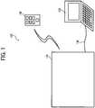
- FIG. 1is a schematic diagram illustrating an image projection system 100.
- the image projection system 100includes a projector 110 and a video source apparatus 120, and the projector 110 is connected to the video source apparatus 120 via a cable 130.
- the projector 110projects an image provided by the video source apparatus 120 on a projection surface such as a screen etc.
- the projector 110projects an OSD screen (superimposed screen) such as a menu screen configurable manually along with the image provided by the video source apparatus 120. It should be noted that the OSD screen can be projected even if the video source apparatus 120 does not provide images.
- the projector 110receives operation requests from a remote control 140 and performs various operations that implements functions that the projector 110 includes.
- the projector 110includes video input ports such as a Video Graphics Array (VGA) input port, a High-Definition Multimedia Interface (HDMI) port, a S-Video port, and a RCA port as interfaces for inputting video signals and receives the video signal from the video source apparatus 120 via the cable 130 connected to those ports.
- VGAVideo Graphics Array
- HDMIHigh-Definition Multimedia Interface
- S-VideoS-Video
- RCA portas interfaces for inputting video signals and receives the video signal from the video source apparatus 120 via the cable 130 connected to those ports.
- the projectorcan receive the video signal from the video source apparatus 120 using wireless communication in conformity with wireless communication protocols such as Bluetooth and Wi-Fi etc.
- the video source apparatus 120provides images that the projector 110 projects.
- the image providing apparatus 120includes interfaces to output video signals and transfers the video signal that forms display images of the video source apparatus 120 to the projector 110 at a predetermined transfer rate (e.g., from 30 frame per second (fps) to 60 fps).
- the video source apparatus 120also includes video output ports such as a VGA output port, the HDMI port, the S-Video port, and the RCA port as interfaces for outputting video signals and transfers the video signal to the projector 110 via the cable 130 connected to those ports.
- video output portssuch as a VGA output port, the HDMI port, the S-Video port, and the RCA port as interfaces for outputting video signals and transfers the video signal to the projector 110 via the cable 130 connected to those ports.
- the video source apparatus 120can transfer the video signal to the projector 110 using wireless communication.
- a notebook PCinformation processing apparatus
- the information processing apparatusthat can provide the video signals such as a desktop PC, a tablet PC and a PDA can be adopted as the video source apparatus 120.
- the video source apparatus 120while one video source apparatus 120 is connected to the projector 110, two or more video source apparatus 120 can be connected to the projector 110.
- FIG. 2is a block diagram illustrating a configuration of the projector 110 in this embodiment.
- the projector 110includes a main board 200, a network board (expansion board) 210, an optical unit 220, a lamp (light source) 221, a power supply 228, and a video signal input interface 230.
- the main board 200is a printed-circuit board that controls the whole part of the projector 110.
- the main board 200includes a system controller 201, a video signal processor 202, a power supply controller 203, a storage device 204, an optical controller 205 and can be configured using integrated circuits that implement the functional units described above such as Application Specific Integrated Circuit (ASIC) etc.
- ASICApplication Specific Integrated Circuit
- the system controller 201controls the whole part of the projector 110.
- the system controller 201is connected to the video signal processor 202, the power supply controller 203, the storage device 204, and the optical controller 205 via a bus and controls each of these functional units.
- the video signal processor 202processes the video signal that the video source apparatus 120 provides.
- the video processor 202receives the video signal via the video signal input interface 230 and performs various processes such as serial-parallel conversion and voltage level conversion etc.
- the power supply controller 203controls the power supply 228 that supplies electric power to the projector 110.
- the power supply controller 203turns on and off the power supply 228 under the control of the system controller 201.
- the storage device 204is nonvolatile memory that stores various data that the system controller 201 processes.
- Various nonvolatile semiconductor memory devicesincluding EPROM, EEPROM, and flash memory can be adopted as the storage device 204.
- the optical controller 205controls the optical unit 220 that forms the video.
- the optical controller 205supplies the image data that the system controller 201 generates to the optical unit 220 and forms the video of the image data.
- the optical unit 220forms the video of the image data projects the image data on the projection surface by illuminating the optical unit 220 with the light generated by the lamp 221.
- the projector 110is a liquid crystal projector, it is possible to adopt a liquid crystal as the optical unit 220.
- the projector 110is a Digital Light Processing (DLP) projector, it is possible to adopt a DMD or a color wheel as the optical unit 220.
- DLPDigital Light Processing
- the lamp controller (light source controller) 222controls the lamp 221 and adjust the amount of light of the lamp 221 under the control of the system controller 201. It is possible to use a high-pressure mercury vapor lamp etc. as the lamp 221.
- the network board 210is a printed-circuit board that controls network communication and an external storage device.
- the network board 210includes a network system controller 211, a network interface 212, a storage device interface 213, and a storage unit 214, and the network board 210 can be configured by integrated circuits such as ASIC that implements the function.
- the network system controller 211controls communication via the network 231 and the storage device 232.
- the network system controller 211is connected to the network interface 212, the storage device interface 213, and the storage unit 214 via a bus.
- the network interface 212communicates data via the network 231.
- the network interface 212provides the data received from the network 231 to the network system controller 211 and sends the data received from the network system controller 211 to the network 231.
- the network interface 212includes a port that can be connected to a network cable such as a LAN cable etc. and performs wired communication via the network cable.
- the network interface 212also includes a wireless communication function such as Bluetooth and Wi-Fi and performs data communication by wireless communication.
- the storage device interface 213is an interface that connects to the portable storage device 232 such as a USB memory.
- the storage device interface 213acquires image data such as an image and video and provides it to the network system controller 211.
- the storage unit 214is a nonvolatile memory that stores various data processed by the network system controller 211.
- various nonvolatile semiconductor memory devicessuch as EPROM, EEPROM, and flash memory, etc., as the storage unit 214.
- the projector 110includes a thermal sensor 223, an acceleration sensor, a display unit 225, an operational unit (main unit keys) 226, a receiver 227, and a cooling device 229, and these functional units are connected to the system controller 201 via a bus.
- the thermal sensor 223detects temperature of the projector 110.
- the thermal sensor 223reports the detected temperature to the system controller 201.
- the acceleration sensor 224detects acceleration of the projector 110.
- the acceleration sensor 224reports the detected temperature to the system controller 201
- the display unit 225displays various information, and the display unit 225 is comprised of a LED indicator and a liquid crystal panel.
- the display unit 225displays information to be displayed received from the system controller 201 on the LED indicator and the liquid crystal panel.
- the operational panel 226accepts various operational requests manually and comprises key buttons (main unit keys) etc. laid out on the outside surface of the projector 110.
- the operational requestsinclude a request to modify aspect ratio of the projected video, a request to turn off the projector 110, a request to change the lamp power to adjust the amount of light of the light source, a request to switch input that changes the image providing apparatus whose display image is to be projected if the multiple image providing apparatuses are connected, a request to change a video mode that changes quality of the projected video (e.g., bright, standard, and natural), a request to freeze that pauses the video to be projected, a request to change input type as type of port from which the image to be projected is acquired, a request to display the main menu screen or the sub-menu screen, a request to modify aspect ratio, and a request to close the sub-menu screen.
- the operational unit 226reports the operational request to the system controller 201.
- the receiver 227receives an operational signal from the remote control 140. After receiving the operational signal, the receiver 227 reports the operational signal to the system controller 201.
- the cooling device 229cools down the projector 110 and is comprised of components such as a cooling fan, etc.
- the cooling device 229is driven under the control of the system controller 201 and cools down the projector 110.
- FIG. 3is a block diagram illustrating a configuration of the main board 200 included in the projector 110.
- the system controller 201includes a main controller 300, an OSD generator 301, a main unit key/remote control controlling unit 302, a projection unit 303, and a lamp power controller 304.
- the main controller 300controls the whole part of the system controller 201.
- the main controller 300controls the system controller 201 and functional units described above.
- the OSD generator 301generates OSD screens such as a menu screen, dialog, message window, icon, and help that the main board 200 generates.
- the OSD generator 301reads menu settings information displayed on the main menu screen from the storage device 204 and generates the main menu screen that reflects the menu settings information.
- the OSD generator 301transfers a video signal that forms the main menu screen to the projection unit 303.
- the main unit key/remote control controlling unit 302accepts various operational requests from the operational unit 226 and the remote control 140 and reports the operational request that corresponds to each operational request.
- the projection unit 303projects image data by controlling the optical controller 205.
- the projection unit 303transfers a video signal that forms an image received from the image providing apparatus 120, a video signal that forms the menu screen etc. acquired from the OSD generator 301, and a video signal that forms a sub-menu screen acquired from the network board 210 to the optical controller 205 and projects those image data.
- the projector 110includes the network board 210, a network board interface that performs data communication between the main board 200 and the network board 210.
- the network board interfacetransfers a request to display the sub-menu screen and close the sub-menu screen to the network board 210 and receives a response signal to these requests and a video signal that forms the sub-menu screen from the network board 210.
- the lamp power controller 304adjusts appropriate output of the lamp according to brightness (gradation) of the video (video signal). For example, as shown in FIG. 4 , the lamp power is set to 240 watts if brightness of the video is 100%, and the lamp power is reduced to minimum of 140 watts according to the brightness of the video.
- the brightness of the video (gradation)means values of brightness or RGB.
- the lamp power control by the lamp power controller 304is referred to as lamp power adjustment setting, and it is preferable that whether or not this function is used (turning on/off the lamp power adjustment setting).
- the lamp power controller 304adjusts the number of gradation of the video signal. That is, by increasing (decreasing) the number of gradation in response to darkness (brightness) due to lamp power control as optical correction, it is possible to save energy without changing the brightness of the output image (outlook brightness in viewpoint of a user).
- FIGS. 5A , 5B and 5Care sequence charts illustrating a process executed by the projector.
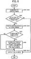
- FIG. 6is a flowchart illustrating steps from S201 to S212 shown in FIG. 5 .
- the image providing apparatus 120is connected to the projector 110 via a cable (D-SUB cable) 130, the image providing apparatus 120 outputs a predetermined video, and the video signal processor 202 receives the video signal from the video source apparatus 120 in S101 (inputting computer video).
- a cableD-SUB cable
- the main controller 300After detecting that the video signal processor 202 receives the video signal in S 102 (inputting computer video), the main controller 300 reads that the lamp power adjustment setting is either on or off from the storage device 204 in S103 (reading the lamp power adjustment setting).
- the main controller 300instructs the lamp power controller 304 to control the lamp power adjustment in S 104 (performing lamp power adjustment).
- the lamp power controller 304After receiving the instruction from the main controller 300, the lamp power controller 304 determines the brightness of the video signal from the brightness histogram of the video and calculates the corresponding lamp power (watts as a percentage of watts at full power).
- the lamp power controller 304sends the calculated lamp power (%) to the lamp controller 222 in S106 (setting lamp power). Subsequently, the lamp controller 222 controls the lamp 221 according to the calculated lamp power (%).
- the main controller 300instructs the projection unit 303 to project the video in S107 (projecting video), and the projection unit 303 transfers the video signal from the video source apparatus 120 to the optical controller 205. Subsequently, the optical controller 205 projects the video signal in S108 (projecting video).
- the OSD screene.g., a menu screen
- the menuis displayed by pressing the menu button on the remote control 140 or the operational unit 226 manually in S201 (operation to display the menu).
- the receiver 227transfers content of the operation to the main unit key/remote control controlling unit 302 in S202 (instructing to display the menu), and the main unit key/remote control controlling unit 302 transfers the instruction to display the menu to the main controller 300 in S203 (instructing to display the menu).
- the main controller 300reads that the lamp power adjustment setting is either on or off from the storage device 204 in S204 (reading setting of lamp power adjustment).
- the main controller 300acquires brightness of the video signal from the lamp power controller 304 in S205 (acquiring brightness of the video signal).
- the brightness of the video signalcan be determined from the brightness histogram of the video.
- the brightness of the video signalcan also be determined from RGB values of the screen.
- the lamp power controller 304determines the brightness of the video signal in S206 (calculating the brightness of the video signal).
- the video signal as the basis of this determinationis input from the video source apparatus 120 before displaying the OSD screen.
- the main controller 300After determining whether or not the brightness of the video signal is equal to or less than a predetermined threshold value, the main controller 300 determines which display pattern of the OSD screen is to be displayed, a first screen pattern (pattern 1) or a second screen pattern (pattern 2) in S207 (determining OSD pattern).
- two screen partsare preliminary prepared as display patterns for the OSD screen, and they are chosen based on the brightness of the video signal.
- the normal casemeans that the brightness of the video signal is equal to or larger than the predetermined value or the lamp power adjustment setting is off (the case in which the OSD screen is not selected according to the projected image).
- the main controller 300instructs the OSD generator 301 to display the menu using the selected OSD screen along with information on which OSD screen pattern is selected in S208 (instructing to display the menu).
- the OSD generator 301reads the menu setting from the storage device 204 in S209 (reading the menu setting) and generates the menu image in S210 (reading the menu setting).
- the OSD generator 301transfers the menu image to the projection unit 303 in S211 (displaying the OSD).
- the projection unit 303transfers the video signal for the menu image to the optical controller 205, and the optical controller 205 projects the video signal in S212 (projecting the video).
- one display patternis projected among multiple patterns of error dialog display by performing steps after S204 by the main controller 300 that received the instruction to display error screen.
- Patterns of menu images that the OSD generator 301 generates depending on the projection imagerepresent not different display content but same information. By making brightness in a part at least different, it is possible to keep visibility of those images high without raising the lamp power even in controlling the lamp power.
- the number of patterns of the OSD screenis not limited to two, and it is possible to use more than three screen patterns. In this case, it is preferable to configure multiple threshold values to determine according to the number of patterns.
- the OSD generator 301generates the first screen pattern normally used and the second screen pattern used under the predetermined condition.
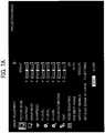
- FIG. 7Ais a diagram illustrating the first screen pattern of the OSD screen normally used
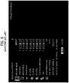
- FIG. 7Bis a diagram illustrating the second screen pattern of .the OSD screen used for the dark screen.
- background part of the screen pattern(parts except for characters, cursor, and icon) is darker than the first screen pattern.
- contrast ratio between the background part and text part including cursor and iconis larger than the first screen pattern. That is, in the second screen pattern, its contrast becomes larger than the first screen pattern by making brightness of texts less dark compared to making the brightness of the background part darker.
- texts in the second screen patternare darker than the first screen pattern.
- the second screen patternis dark image in whole. It is possible to prevent the lamp power from becoming large when the lamp power controller 304 controls the lamp power in S106 and keep visibility of the screen by maintaining the predetermined contrast.
- Examples of the different screen patternsare not limited to the above description.
- settings on font and text size of text partsare different between the first screen pattern and the second screen pattern, and in the second screen pattern, it is possible to prevent the lamp power from becoming large when the lamp power controller 304 controls the lamp power in S106.
- the first screen patternis used by default, and the OSD is displayed after changing into the second screen pattern if the brightness of the video signal is equal to or less than a predetermined threshold value.
- a predetermined threshold valueit is possible to change into the second screen pattern if the brightness of 90% of the pixels is equal to or less than 30/255 for example. Since different types of lamp have different brightness and the visibility of the OSD screen is different, it is possible to check the projection screen in designing the projector and configure the optimal value.
- the main controller 300selects the screen pattern of the OSD screen based on the brightness of the video (the number of gradations of brightness and RGB values). However, it is possible to configure the threshold value of the lamp power using the lamp power (%) that the lamp power controller 304 calculates from the brightness of the video as criteria. Alternatively, it is possible to select the screen pattern of the OSD screen using both the brightness of the video and the lamp power as criteria.
- the OSD generator 301stores the predetermined number of screen patterns preliminarily. Other than that, it is possible to calculate optimal brightness values of backgrounds and texts in the screen pattern. For example, it is possible to calculate the brightness of the background and text parts of the OSD screen according to average value of brightness of the detected video signal etc. and project the video. Consequently, it is possible to display the OSD screen with appropriate brightness according to the brightness of the video signal.
- the OSD screenin case of displaying the OSD screen when the lamp power is reduced by the adjustment control of the lamp power, the OSD screen is changed into the screen pattern for dark screens in order to prevent the lamp power from becoming large making the lamp brighter.
- the visibility of the OSD screengets degraded in case of making the whole screen dark colors.
- contrast between the background and the parts such as texts and cursorsis maintained high more than the predetermined value. Consequently, it is possible to maintain the energy-saving effect in adjusting and controlling the lamp power and project the OSD screen maintaining its visibility.
- this inventionmay be implemented as convenient using a conventional general-purpose digital computer programmed according to the teachings of the present specification.
- Appropriate software codingcan readily be prepared by skilled programmers based on the teachings of the present disclosure, as will be apparent to those skilled in the software arts.
- the present inventionmay also be implemented by the preparation of application-specific integrated circuits or by interconnecting an appropriate network of conventional component circuits, as will be readily apparent to those skilled in the relevant art.
- a processing circuitincludes a programmed processor, as a processor includes circuitry.
- a processing circuitalso includes devices such as an application specific integrated circuit (ASIC) and conventional circuit components arranged to perform the recited functions.
- ASICapplication specific integrated circuit
Landscapes
- Engineering & Computer Science (AREA)
- Multimedia (AREA)
- Signal Processing (AREA)
- Human Computer Interaction (AREA)
- Controls And Circuits For Display Device (AREA)
- Transforming Electric Information Into Light Information (AREA)
- Projection Apparatus (AREA)
- Control Of Indicators Other Than Cathode Ray Tubes (AREA)
Description
- The present invention relates to a projector, a projector control method, and a recording medium storing a projector control program.
- Recently, with projectors, their liquid crystal panels have become high-resolution, their brightness has been improved with high-efficiency lamps, and they have become less expensive. For example, compact and lightweight projectors that adopt a Digital Micro-mirror Device (DMD) have become popular, and those projectors have become widely used not only in workplaces and schools but also in homes. In particular, portability of front type projectors has been improved, and they have come to be used for especially small or ad hoc meetings with only several attendees.
- Aside from images input from information processing apparatuses such as personal computers (PCs) connected to the projectors and which the projector projects on a screen, projectors also have an On Screen Display (OSD) function that projects a menu screen, etc., that enables various operations and settings input to the projectors.
- On the menu screen displayed by the OSD function, various settings such as display language, display mode, image adjustment, and power management can be configured manually. In addition, error display screens, etc., are also displayed by the OSD function. Hereinafter, a menu or error screen, etc., which may be projected using the OSD function, is referred to as an OSD screen.
- In the recent projectors, output of a light source (lamp power) may be controlled according to brightness (gradation) of a video signal, thus preventing dynamic range and image quality from deteriorating while achieving energy reduction, for example, as described in
JP 2002-156951-A - For example, output of the lamp may be modified according to the number of gradations of the input signal, so that the lamp power is boosted in the case of bright images and reduced in the case of dark images. For example, if a dark image is input to the projector, not only are dark colors displayed by the image display device (liquid crystal or DMD) but the output of the lamp is also reduced. By performing the process described above, it is possible to make the number of expressible gradations on the projection screen "the number of gradations expressible by the image display device" by "width of brightness expressible by the lamp".
- In the projectors that boost the lamp power in the case of bright images and reduce the lamp power in the case of dark images (hereinafter referred to as "lamp power adjustment control"), in case of projecting the dark image (projection image) shown in
FIG. 8 , it is possible to keep the lamp power low by the lamp power adjustment control. However, from that status, if the menu screen prepared preliminary is displayed by the OSD function as shown inFIG. 9 , since the brightness of the menu screen is configured as high, the lamp power is boosted by the lamp power adjustment control. By boosting the lamp power as described above, the energy-saving effect that the lamp power adjustment control aims to achieve originally is lost. - In displaying the menu screen by the OSD function, it is possible to adjust and control the lamp power based on the brightness of the projection image before projecting the menu screen and keep the lamp power low by adjusting and controlling the lamp power. However, if the menu screen is displayed while the lamp power is kept low, the menu screen also gets dark as shown in
FIG. 10 , degrading the visibility of the menu screen. - In view of the above, there is a need for a projector that can maintain the energy reduction of the lamp power adjustment control by controlling the displayed OSD screen selectively depending on the projection image and keeps projecting the OSD screen with high visibility.
US2007/046829A discloses a projector having an OSD menu, using a microprocessor to control image projector lamp power according to thresholds applied to a video signal brightness.US2004/0095358A discloses an OSD whose brightness is adjustable.- The present invention is in the projector of
claim 1 and the method of claim 3. - A more complete appreciation of the disclosure and many of the attendant advantages thereof will be readily obtained as the same becomes better understood by reference to the following detailed description when considered in conjunction with the accompanying drawings.
FIG. 1 is a schematic diagram illustrating an image projection system as an embodiment of the present invention.FIG. 2 is a block diagram illustrating a configuration of a projector as an embodiment of the present invention.FIG. 3 is a block diagram illustrating a configuration of a main board in the projector as an embodiment of the present invention.FIG. 4 is a diagram illustrating a corresponding relationship between brightness of video and lamp power.FIGS. 5A ,5B and5C are sequence charts illustrating a process executed by the projector.FIG. 6 is a flowchart illustrating a process executed by the projector.FIG. 7A is a diagram illustrating a first screen pattern of the OSD screen, andFIG. 7B is a diagram illustrating a second screen pattern of the OSD screen.FIG. 8 is a diagram illustrating a projection image.FIG. 9 is a diagram illustrating the menu screen superimposed on the projection screen shown inFIG. 8 (with lamp power adjustment control in displaying the menu screen).FIG. 10 is a diagram illustrating the menu screen superimposed on the projection screen shown inFIG. 8 (without lamp power adjustment control in displaying the menu screen).- In describing preferred embodiments illustrated in the drawings, specific terminology is employed for the sake of clarity. However, the disclosure of this patent specification is not intended to be limited to the specific terminology so selected, and it is to be understood that each specific element includes all technical equivalents that have the same function, operate in a similar manner, and achieve a similar result.
- In the following embodiment, a projector that can maintain the energy reduction of the lamp power adjustment control by controlling the displayed OSD screen selectively depending on the projection image and keeps projecting the OSD screen with high visibility is provided.
- The
projector 110 in this embodiment generates the projection image based on the video signal and projects the projection image on the projection surface. Theprojector 110 includes a light source output adjustment unit (lamp power controller 304) that controls output of the light source (lamp 221) according to brightness of the video signal and a superimposed image projection unit (OSD generator 301 and main controller 300) that superimposes a predetermined superimposed screen (OSD screen) on the generated projection image based on the video signal and projects the projection image. The superimposed image projection unit generates multiple images having identical content but at least partially different brightness (the first screen pattern and the second screen pattern inFIG. 7 ) and projects the different superimposed image depending on the projection image. FIG. 1 is a schematic diagram illustrating animage projection system 100. Theimage projection system 100 includes aprojector 110 and avideo source apparatus 120, and theprojector 110 is connected to thevideo source apparatus 120 via acable 130.- The
projector 110 projects an image provided by thevideo source apparatus 120 on a projection surface such as a screen etc. Theprojector 110 projects an OSD screen (superimposed screen) such as a menu screen configurable manually along with the image provided by thevideo source apparatus 120. It should be noted that the OSD screen can be projected even if thevideo source apparatus 120 does not provide images. In addition, theprojector 110 receives operation requests from aremote control 140 and performs various operations that implements functions that theprojector 110 includes. - The
projector 110 includes video input ports such as a Video Graphics Array (VGA) input port, a High-Definition Multimedia Interface (HDMI) port, a S-Video port, and a RCA port as interfaces for inputting video signals and receives the video signal from thevideo source apparatus 120 via thecable 130 connected to those ports. - Alternatively, the projector can receive the video signal from the
video source apparatus 120 using wireless communication in conformity with wireless communication protocols such as Bluetooth and Wi-Fi etc. - The
video source apparatus 120 provides images that theprojector 110 projects. Theimage providing apparatus 120 includes interfaces to output video signals and transfers the video signal that forms display images of thevideo source apparatus 120 to theprojector 110 at a predetermined transfer rate (e.g., from 30 frame per second (fps) to 60 fps). - The
video source apparatus 120 also includes video output ports such as a VGA output port, the HDMI port, the S-Video port, and the RCA port as interfaces for outputting video signals and transfers the video signal to theprojector 110 via thecable 130 connected to those ports. - In addition, the
video source apparatus 120 can transfer the video signal to theprojector 110 using wireless communication. - For example, a notebook PC (information processing apparatus) can be used as the
video source apparatus 120. In addition, the information processing apparatus that can provide the video signals such as a desktop PC, a tablet PC and a PDA can be adopted as thevideo source apparatus 120. InFIG. 1 , while onevideo source apparatus 120 is connected to theprojector 110, two or morevideo source apparatus 120 can be connected to theprojector 110. FIG. 2 is a block diagram illustrating a configuration of theprojector 110 in this embodiment. Theprojector 110 includes amain board 200, a network board (expansion board) 210, an optical unit 220, a lamp (light source) 221, apower supply 228, and a videosignal input interface 230.- The
main board 200 is a printed-circuit board that controls the whole part of theprojector 110. Themain board 200 includes asystem controller 201, avideo signal processor 202, apower supply controller 203, astorage device 204, anoptical controller 205 and can be configured using integrated circuits that implement the functional units described above such as Application Specific Integrated Circuit (ASIC) etc. - The
system controller 201 controls the whole part of theprojector 110. Thesystem controller 201 is connected to thevideo signal processor 202, thepower supply controller 203, thestorage device 204, and theoptical controller 205 via a bus and controls each of these functional units. - The
video signal processor 202 processes the video signal that thevideo source apparatus 120 provides. Thevideo processor 202 receives the video signal via the videosignal input interface 230 and performs various processes such as serial-parallel conversion and voltage level conversion etc. - The
power supply controller 203 controls thepower supply 228 that supplies electric power to theprojector 110. Thepower supply controller 203 turns on and off thepower supply 228 under the control of thesystem controller 201. - The
storage device 204 is nonvolatile memory that stores various data that thesystem controller 201 processes. Various nonvolatile semiconductor memory devices including EPROM, EEPROM, and flash memory can be adopted as thestorage device 204. - The
optical controller 205 controls the optical unit 220 that forms the video. Theoptical controller 205 supplies the image data that thesystem controller 201 generates to the optical unit 220 and forms the video of the image data. The optical unit 220 forms the video of the image data projects the image data on the projection surface by illuminating the optical unit 220 with the light generated by thelamp 221. If theprojector 110 is a liquid crystal projector, it is possible to adopt a liquid crystal as the optical unit 220. If theprojector 110 is a Digital Light Processing (DLP) projector, it is possible to adopt a DMD or a color wheel as the optical unit 220. - The lamp controller (light source controller) 222 controls the
lamp 221 and adjust the amount of light of thelamp 221 under the control of thesystem controller 201. It is possible to use a high-pressure mercury vapor lamp etc. as thelamp 221. - The
network board 210 is a printed-circuit board that controls network communication and an external storage device. Thenetwork board 210 includes anetwork system controller 211, anetwork interface 212, astorage device interface 213, and astorage unit 214, and thenetwork board 210 can be configured by integrated circuits such as ASIC that implements the function. - The
network system controller 211 controls communication via thenetwork 231 and thestorage device 232. Thenetwork system controller 211 is connected to thenetwork interface 212, thestorage device interface 213, and thestorage unit 214 via a bus. - The
network interface 212 communicates data via thenetwork 231. Thenetwork interface 212 provides the data received from thenetwork 231 to thenetwork system controller 211 and sends the data received from thenetwork system controller 211 to thenetwork 231. Thenetwork interface 212 includes a port that can be connected to a network cable such as a LAN cable etc. and performs wired communication via the network cable. Thenetwork interface 212 also includes a wireless communication function such as Bluetooth and Wi-Fi and performs data communication by wireless communication. - The
storage device interface 213 is an interface that connects to theportable storage device 232 such as a USB memory. Thestorage device interface 213 acquires image data such as an image and video and provides it to thenetwork system controller 211. - The
storage unit 214 is a nonvolatile memory that stores various data processed by thenetwork system controller 211. In this embodiment, it is possible to adopt various nonvolatile semiconductor memory devices, such as EPROM, EEPROM, and flash memory, etc., as thestorage unit 214. - In addition, the
projector 110 includes athermal sensor 223, an acceleration sensor, adisplay unit 225, an operational unit (main unit keys) 226, areceiver 227, and acooling device 229, and these functional units are connected to thesystem controller 201 via a bus. - The
thermal sensor 223 detects temperature of theprojector 110. Thethermal sensor 223 reports the detected temperature to thesystem controller 201. - The
acceleration sensor 224 detects acceleration of theprojector 110. Theacceleration sensor 224 reports the detected temperature to thesystem controller 201 - The
display unit 225 displays various information, and thedisplay unit 225 is comprised of a LED indicator and a liquid crystal panel. Thedisplay unit 225 displays information to be displayed received from thesystem controller 201 on the LED indicator and the liquid crystal panel. - The
operational panel 226 accepts various operational requests manually and comprises key buttons (main unit keys) etc. laid out on the outside surface of theprojector 110. The operational requests include a request to modify aspect ratio of the projected video, a request to turn off theprojector 110, a request to change the lamp power to adjust the amount of light of the light source, a request to switch input that changes the image providing apparatus whose display image is to be projected if the multiple image providing apparatuses are connected, a request to change a video mode that changes quality of the projected video (e.g., bright, standard, and natural), a request to freeze that pauses the video to be projected, a request to change input type as type of port from which the image to be projected is acquired, a request to display the main menu screen or the sub-menu screen, a request to modify aspect ratio, and a request to close the sub-menu screen. After accepting the operational request, theoperational unit 226 reports the operational request to thesystem controller 201. - The
receiver 227 receives an operational signal from theremote control 140. After receiving the operational signal, thereceiver 227 reports the operational signal to thesystem controller 201. - The
cooling device 229 cools down theprojector 110 and is comprised of components such as a cooling fan, etc. Thecooling device 229 is driven under the control of thesystem controller 201 and cools down theprojector 110. FIG. 3 is a block diagram illustrating a configuration of themain board 200 included in theprojector 110.- The
system controller 201 includes amain controller 300, anOSD generator 301, a main unit key/remotecontrol controlling unit 302, aprojection unit 303, and alamp power controller 304. - The
main controller 300 controls the whole part of thesystem controller 201. Themain controller 300 controls thesystem controller 201 and functional units described above. - The
OSD generator 301 generates OSD screens such as a menu screen, dialog, message window, icon, and help that themain board 200 generates. TheOSD generator 301 reads menu settings information displayed on the main menu screen from thestorage device 204 and generates the main menu screen that reflects the menu settings information. TheOSD generator 301 transfers a video signal that forms the main menu screen to theprojection unit 303. - The main unit key/remote
control controlling unit 302 accepts various operational requests from theoperational unit 226 and theremote control 140 and reports the operational request that corresponds to each operational request. - The
projection unit 303 projects image data by controlling theoptical controller 205. Theprojection unit 303 transfers a video signal that forms an image received from theimage providing apparatus 120, a video signal that forms the menu screen etc. acquired from theOSD generator 301, and a video signal that forms a sub-menu screen acquired from thenetwork board 210 to theoptical controller 205 and projects those image data. - If the
projector 110 includes thenetwork board 210, a network board interface that performs data communication between themain board 200 and thenetwork board 210. The network board interface transfers a request to display the sub-menu screen and close the sub-menu screen to thenetwork board 210 and receives a response signal to these requests and a video signal that forms the sub-menu screen from thenetwork board 210. - The
lamp power controller 304 adjusts appropriate output of the lamp according to brightness (gradation) of the video (video signal). For example, as shown inFIG. 4 , the lamp power is set to 240 watts if brightness of the video is 100%, and the lamp power is reduced to minimum of 140 watts according to the brightness of the video. Here, the brightness of the video (gradation) means values of brightness or RGB. - The lamp power control by the
lamp power controller 304 is referred to as lamp power adjustment setting, and it is preferable that whether or not this function is used (turning on/off the lamp power adjustment setting). - In adjusting the lamp power, it is preferable that the
lamp power controller 304 adjusts the number of gradation of the video signal. That is, by increasing (decreasing) the number of gradation in response to darkness (brightness) due to lamp power control as optical correction, it is possible to save energy without changing the brightness of the output image (outlook brightness in viewpoint of a user). FIGS. 5A ,5B and5C are sequence charts illustrating a process executed by the projector.FIG. 6 is a flowchart illustrating steps from S201 to S212 shown inFIG. 5 .- How the video provided by the
video source apparatus 120 is input into theprojector 110 and is projected is described below. First, theimage providing apparatus 120 is connected to theprojector 110 via a cable (D-SUB cable) 130, theimage providing apparatus 120 outputs a predetermined video, and thevideo signal processor 202 receives the video signal from thevideo source apparatus 120 in S101 (inputting computer video). - After detecting that the
video signal processor 202 receives the video signal in S 102 (inputting computer video), themain controller 300 reads that the lamp power adjustment setting is either on or off from thestorage device 204 in S103 (reading the lamp power adjustment setting). - If the lamp power adjustment setting is on, the
main controller 300 instructs thelamp power controller 304 to control the lamp power adjustment in S 104 (performing lamp power adjustment). - After receiving the instruction from the
main controller 300, thelamp power controller 304 determines the brightness of the video signal from the brightness histogram of the video and calculates the corresponding lamp power (watts as a percentage of watts at full power). - Next, the
lamp power controller 304 sends the calculated lamp power (%) to thelamp controller 222 in S106 (setting lamp power). Subsequently, thelamp controller 222 controls thelamp 221 according to the calculated lamp power (%). - Next, the
main controller 300 instructs theprojection unit 303 to project the video in S107 (projecting video), and theprojection unit 303 transfers the video signal from thevideo source apparatus 120 to theoptical controller 205. Subsequently, theoptical controller 205 projects the video signal in S108 (projecting video). - Next, how the OSD screen (e.g., a menu screen) is displayed after projecting the video from the
video source apparatus 120 is described below. First, the menu is displayed by pressing the menu button on theremote control 140 or theoperational unit 226 manually in S201 (operation to display the menu). - Next, the
receiver 227 transfers content of the operation to the main unit key/remotecontrol controlling unit 302 in S202 (instructing to display the menu), and the main unit key/remotecontrol controlling unit 302 transfers the instruction to display the menu to themain controller 300 in S203 (instructing to display the menu). - The
main controller 300 reads that the lamp power adjustment setting is either on or off from thestorage device 204 in S204 (reading setting of lamp power adjustment). - If the lamp power adjustment setting is on, the
main controller 300 acquires brightness of the video signal from thelamp power controller 304 in S205 (acquiring brightness of the video signal). For example, the brightness of the video signal can be determined from the brightness histogram of the video. However, this is just an example, and the brightness of the video signal can also be determined from RGB values of the screen. - The
lamp power controller 304 determines the brightness of the video signal in S206 (calculating the brightness of the video signal). The video signal as the basis of this determination is input from thevideo source apparatus 120 before displaying the OSD screen. - After determining whether or not the brightness of the video signal is equal to or less than a predetermined threshold value, the
main controller 300 determines which display pattern of the OSD screen is to be displayed, a first screen pattern (pattern 1) or a second screen pattern (pattern 2) in S207 (determining OSD pattern). - In this embodiment, two screen parts, the first screen pattern normally used and the second screen pattern used for dark screens, are preliminary prepared as display patterns for the OSD screen, and they are chosen based on the brightness of the video signal. Here, "the normal case" means that the brightness of the video signal is equal to or larger than the predetermined value or the lamp power adjustment setting is off (the case in which the OSD screen is not selected according to the projected image).
- Next, the
main controller 300 instructs theOSD generator 301 to display the menu using the selected OSD screen along with information on which OSD screen pattern is selected in S208 (instructing to display the menu). - Depending on the designated OSD screen pattern, the
OSD generator 301 reads the menu setting from thestorage device 204 in S209 (reading the menu setting) and generates the menu image in S210 (reading the menu setting). - Next, the
OSD generator 301 transfers the menu image to theprojection unit 303 in S211 (displaying the OSD). Theprojection unit 303 transfers the video signal for the menu image to theoptical controller 205, and theoptical controller 205 projects the video signal in S212 (projecting the video). By performing the control described above, it is possible to project the OSD screen selected according to the brightness of the video on the projection surface where the video from thevideo source apparatus 120 is projected. - As described above, how the menu screen is displayed based on the instruction manually is described with reference to
FIG. 5 andFIG. 6 . Regarding the OSD screens other than the menu screen such as displaying an error dialog due to error occurrence, one display pattern is projected among multiple patterns of error dialog display by performing steps after S204 by themain controller 300 that received the instruction to display error screen. - Patterns of menu images that the
OSD generator 301 generates depending on the projection image represent not different display content but same information. By making brightness in a part at least different, it is possible to keep visibility of those images high without raising the lamp power even in controlling the lamp power. - In this embodiment, there are two patterns of the menu screen that the
OSD generator 301 generates, the first screen pattern normally used and the second screen pattern. However, the number of patterns of the OSD screen is not limited to two, and it is possible to use more than three screen patterns. In this case, it is preferable to configure multiple threshold values to determine according to the number of patterns. - The
OSD generator 301 generates the first screen pattern normally used and the second screen pattern used under the predetermined condition.FIG. 7A is a diagram illustrating the first screen pattern of the OSD screen normally used, andFIG. 7B is a diagram illustrating the second screen pattern of .the OSD screen used for the dark screen. - In the screen patterns shown in
FIGS. 7A and7B , in the second screen pattern, background part of the screen pattern (parts except for characters, cursor, and icon) is darker than the first screen pattern. In addition, in the second screen pattern, contrast ratio between the background part and text part including cursor and icon is larger than the first screen pattern. That is, in the second screen pattern, its contrast becomes larger than the first screen pattern by making brightness of texts less dark compared to making the brightness of the background part darker. InFIG. 7 , texts in the second screen pattern are darker than the first screen pattern. However, it is not limited to that example, and it is possible to make the brightness of text parts same in both two patterns. - By adopting the configuration described above, the second screen pattern is dark image in whole. It is possible to prevent the lamp power from becoming large when the
lamp power controller 304 controls the lamp power in S106 and keep visibility of the screen by maintaining the predetermined contrast. - As shown in
FIG. 7A , in the first screen pattern, background parts of strings such as "CONTRAST" and "SHARPNESS" look brighter than background parts of strings such as "BRIGHTNESS" and "R-LEVEL", and the background parts corresponding to the strings have striped different brightness alternately. By contrast, as shown inFIG. 7B , in the second screen pattern, the background parts of each string look uniformly dark. Consequently, it is possible to prevent the lamp power from becoming large when thelamp power controller 304 controls the lamp power in S106. - Examples of the different screen patterns are not limited to the above description. For example, settings on font and text size of text parts are different between the first screen pattern and the second screen pattern, and in the second screen pattern, it is possible to prevent the lamp power from becoming large when the
lamp power controller 304 controls the lamp power in S106. - In this embodiment, the first screen pattern is used by default, and the OSD is displayed after changing into the second screen pattern if the brightness of the video signal is equal to or less than a predetermined threshold value. In this case, it is possible to change into the second screen pattern if the brightness of 90% of the pixels is equal to or less than 30/255 for example. Since different types of lamp have different brightness and the visibility of the OSD screen is different, it is possible to check the projection screen in designing the projector and configure the optimal value.
- In the embodiment described above, the
main controller 300 selects the screen pattern of the OSD screen based on the brightness of the video (the number of gradations of brightness and RGB values). However, it is possible to configure the threshold value of the lamp power using the lamp power (%) that thelamp power controller 304 calculates from the brightness of the video as criteria. Alternatively, it is possible to select the screen pattern of the OSD screen using both the brightness of the video and the lamp power as criteria. - In the above description, the
OSD generator 301 stores the predetermined number of screen patterns preliminarily. Other than that, it is possible to calculate optimal brightness values of backgrounds and texts in the screen pattern. For example, it is possible to calculate the brightness of the background and text parts of the OSD screen according to average value of brightness of the detected video signal etc. and project the video. Consequently, it is possible to display the OSD screen with appropriate brightness according to the brightness of the video signal. - As described above, in the projector in this embodiment, in case of displaying the OSD screen when the lamp power is reduced by the adjustment control of the lamp power, the OSD screen is changed into the screen pattern for dark screens in order to prevent the lamp power from becoming large making the lamp brighter. In this case, in displaying the screen pattern for dark screens, the visibility of the OSD screen gets degraded in case of making the whole screen dark colors. To cope with this issue, contrast between the background and the parts such as texts and cursors is maintained high more than the predetermined value. Consequently, it is possible to maintain the energy-saving effect in adjusting and controlling the lamp power and project the OSD screen maintaining its visibility.
- Numerous additional modifications and variations are possible in light of the above teachings. It is therefore to be understood that, within the scope of the appended claims, the disclosure of this patent specification may be practiced otherwise than as specifically described herein.
- As can be appreciated by those skilled in the computer arts, this invention may be implemented as convenient using a conventional general-purpose digital computer programmed according to the teachings of the present specification. Appropriate software coding can readily be prepared by skilled programmers based on the teachings of the present disclosure, as will be apparent to those skilled in the software arts. The present invention may also be implemented by the preparation of application-specific integrated circuits or by interconnecting an appropriate network of conventional component circuits, as will be readily apparent to those skilled in the relevant art.
- Each of the functions of the described embodiments may be implemented by one or more processing circuits. A processing circuit includes a programmed processor, as a processor includes circuitry. A processing circuit also includes devices such as an application specific integrated circuit (ASIC) and conventional circuit components arranged to perform the recited functions.
Claims (4)
- A projector (110), comprising:a light source (221);a light source output adjustment unit (304) configured to control output of the light source (221) according to the brightness of a video signal input to the projector (110); anda superimposed image projection unit (301, 300) configured to superimpose an OSD, On Screen Display, image onto a projection image generated according to the video signal;wherein the superimposed image projection unit (301, 300) is configured to store OSD images indicating the same content but whose brightnesses are different from one another, and to select, superimpose and project one of the multiple OSD images based on the brightness of the video signal;wherein the superimposed image projection unit (301, 300) is configured to store a first image pattern and a second image pattern having a darker background and a greater contrast between background and text than the first image pattern, amongst the multiple OSD images, and to project the second image pattern if the brightness of the video signal is equal to or less than a predetermined threshold value;and wherein the text parts of the first and second image patterns have different settings on font and text size.
- A projector according to claim 1, wherein the OSD images have a background to each of a plurality of strings of the text, and the background in the first image pattern has alternating bands of different brightness between the strings, whereas the background of the second image pattern has a uniform brightness.
- A method of controlling a projection image, comprising the steps of:controlling the output of a projector light source (221) according to the brightness of a video signal;storing multiple OSD, On Screen Display, images indicating the same content but whose brightnesses are different from one another, the OSD images comprising a first image pattern and a second image pattern having a darker background and a greater contrast between background and text than the first image pattern, amongst the multiple OSD images, wherein the text parts of the first and second image patterns have different settings on font and text size;selecting, based on the brightness of the video signal, and superimposing one of the multiple OSD images onto a projection image generated according to the video signal; andprojecting the projection image and the superimposed OSD.
- A computer-readable recording medium storing a program that, when executed by a projector (110), causes the projector (110) to perform the image projection control method of claim 3.
Applications Claiming Priority (1)
| Application Number | Priority Date | Filing Date | Title |
|---|---|---|---|
| JP2013144434AJP2015018071A (en) | 2013-07-10 | 2013-07-10 | Image projection device, control method of image projection device and control program of image projection device |
Publications (3)
| Publication Number | Publication Date |
|---|---|
| EP2827590A2 EP2827590A2 (en) | 2015-01-21 |
| EP2827590A3 EP2827590A3 (en) | 2015-03-04 |
| EP2827590B1true EP2827590B1 (en) | 2017-09-27 |
Family
ID=51176124
Family Applications (1)
| Application Number | Title | Priority Date | Filing Date |
|---|---|---|---|
| EP14175462.2ANot-in-forceEP2827590B1 (en) | 2013-07-10 | 2014-07-02 | Projector, projector control method, and recording medium storing projector control program |
Country Status (4)
| Country | Link |
|---|---|
| US (1) | US9300905B2 (en) |
| EP (1) | EP2827590B1 (en) |
| JP (1) | JP2015018071A (en) |
| CN (1) | CN104284118A (en) |
Families Citing this family (5)
| Publication number | Priority date | Publication date | Assignee | Title |
|---|---|---|---|---|
| US10356361B2 (en) | 2016-09-16 | 2019-07-16 | Ricoh Company, Ltd. | Communication terminal, communication system, and display method |
| CN107454133B (en)* | 2017-03-31 | 2020-09-29 | 二极科技有限公司 | A control system and control method |
| CN108737798A (en) | 2017-04-17 | 2018-11-02 | 深圳市光峰光电技术有限公司 | Optical projection system and projecting method |
| JP2019090858A (en)* | 2017-11-10 | 2019-06-13 | キヤノン株式会社 | Display device, display controller and display control method |
| CN111526343B (en)* | 2019-02-01 | 2022-03-01 | 中国电影器材有限责任公司 | Digital film projection method and system |
Family Cites Families (20)
| Publication number | Priority date | Publication date | Assignee | Title |
|---|---|---|---|---|
| JPS60107696A (en)* | 1983-11-16 | 1985-06-13 | 株式会社リコー | Display unit having attribute control function |
| JP2000214838A (en)* | 1999-01-27 | 2000-08-04 | Fuji Photo Film Co Ltd | Display |
| JP4819255B2 (en) | 2000-08-14 | 2011-11-24 | キヤノン株式会社 | Display device |
| JP2003177727A (en)* | 2001-12-13 | 2003-06-27 | Nec Viewtechnology Ltd | Image display device and light quantity adjusting method |
| AU2003209949A1 (en)* | 2002-03-28 | 2003-10-13 | Philips Intellectual Property And Standards Gmbh | Image projector with light source modulation according to image signal |
| JP2004172792A (en)* | 2002-11-19 | 2004-06-17 | Funai Electric Co Ltd | Receiver |
| JP2004341206A (en)* | 2003-05-15 | 2004-12-02 | Olympus Corp | Display apparatus |
| JP4768232B2 (en)* | 2004-05-06 | 2011-09-07 | シャープ株式会社 | Image display device |
| US7643095B2 (en)* | 2004-05-28 | 2010-01-05 | Sharp Kabushiki Kaisha | Image display device, image display method, and television receiver |
| JP2006148766A (en)* | 2004-11-24 | 2006-06-08 | Canon Inc | Video display device |
| KR100620966B1 (en)* | 2004-12-15 | 2006-09-19 | 삼성전자주식회사 | Screen adaptive power control device and method |
| JP2006184567A (en)* | 2004-12-27 | 2006-07-13 | Toshiba Corp | Projection image display device and brightness adjustment method thereof |
| TWI285863B (en)* | 2005-08-30 | 2007-08-21 | Delta Electronics Inc | Apparatus and method for enhancing image contrast |
| JP4030573B2 (en)* | 2006-02-08 | 2008-01-09 | シャープ株式会社 | Liquid crystal display |
| US20080043031A1 (en)* | 2006-08-15 | 2008-02-21 | Ati Technologies, Inc. | Picture adjustment methods and apparatus for image display device |
| JP2008092316A (en)* | 2006-10-03 | 2008-04-17 | Matsushita Electric Ind Co Ltd | Display device |
| JP2008304580A (en)* | 2007-06-06 | 2008-12-18 | Sharp Corp | Image display device |
| JP5556150B2 (en)* | 2009-11-30 | 2014-07-23 | セイコーエプソン株式会社 | Projector and control method thereof |
| US20120075353A1 (en)* | 2010-09-27 | 2012-03-29 | Ati Technologies Ulc | System and Method for Providing Control Data for Dynamically Adjusting Lighting and Adjusting Video Pixel Data for a Display to Substantially Maintain Image Display Quality While Reducing Power Consumption |
| JP6035743B2 (en) | 2012-01-06 | 2016-11-30 | 株式会社リコー | Image output apparatus, method and program |
- 2013
- 2013-07-10JPJP2013144434Apatent/JP2015018071A/enactivePending
- 2014
- 2014-07-02EPEP14175462.2Apatent/EP2827590B1/ennot_activeNot-in-force
- 2014-07-03USUS14/323,187patent/US9300905B2/ennot_activeExpired - Fee Related
- 2014-07-09CNCN201410325823.1Apatent/CN104284118A/enactivePending
Non-Patent Citations (1)
| Title |
|---|
| None* |
Also Published As
| Publication number | Publication date |
|---|---|
| US20150015786A1 (en) | 2015-01-15 |
| CN104284118A (en) | 2015-01-14 |
| EP2827590A3 (en) | 2015-03-04 |
| US9300905B2 (en) | 2016-03-29 |
| EP2827590A2 (en) | 2015-01-21 |
| JP2015018071A (en) | 2015-01-29 |
Similar Documents
| Publication | Publication Date | Title |
|---|---|---|
| KR102366230B1 (en) | Display apparatus and control method thereof | |
| EP2827590B1 (en) | Projector, projector control method, and recording medium storing projector control program | |
| EP2824936B1 (en) | Projector, projector control method, and recording medium storing projector control program | |
| KR20160064900A (en) | Apparatus and method for controlling video wall | |
| US10242607B2 (en) | Display system, display apparatus, method of controlling display apparatus, and program | |
| US8462273B2 (en) | Image display device, projector, control method and computer program product | |
| JP5509729B2 (en) | Image display apparatus, image display method, and image processing apparatus | |
| EP1962179A1 (en) | Display system, control method of the same and control method of video source apparatus | |
| TWI792817B (en) | Display apparatus and dimming-calibration method thereof | |
| WO2019201021A1 (en) | Display screen backlight luminance control method for electronic device, and electronic device | |
| US11363193B2 (en) | Electronic apparatus and image correction method thereof | |
| US9307210B2 (en) | Image output apparatus, method, and medium | |
| US10506209B2 (en) | Image output control device, image output control method, image output system, and recording medium | |
| JP5310973B2 (en) | PC, projection system and projection method | |
| JP5212593B2 (en) | Projector, projection system, and projection method | |
| US10891098B2 (en) | Display device and method for controlling display device | |
| US20130021383A1 (en) | Control apparatus and control method thereof | |
| JP2017203948A (en) | Display device and control method thereof | |
| US20210304472A1 (en) | Method of controlling display device, information processing device, and display system | |
| KR20080085500A (en) | How to control your monitor using a computer | |
| JP2017092849A (en) | Image display system | |
| JP4541863B2 (en) | Display device, display system, display control method, and program | |
| JP2023093337A (en) | Display device and method for preventing image burn-in thereof | |
| CN116416886A (en) | Display device and screen dimming method thereof | |
| CN116343711A (en) | Display device and picture burn-in preventing method thereof |
Legal Events
| Date | Code | Title | Description |
|---|---|---|---|
| 17P | Request for examination filed | Effective date:20140702 | |
| AK | Designated contracting states | Kind code of ref document:A2 Designated state(s):AL AT BE BG CH CY CZ DE DK EE ES FI FR GB GR HR HU IE IS IT LI LT LU LV MC MK MT NL NO PL PT RO RS SE SI SK SM TR | |
| AX | Request for extension of the european patent | Extension state:BA ME | |
| PUAI | Public reference made under article 153(3) epc to a published international application that has entered the european phase | Free format text:ORIGINAL CODE: 0009012 | |
| PUAL | Search report despatched | Free format text:ORIGINAL CODE: 0009013 | |
| AK | Designated contracting states | Kind code of ref document:A3 Designated state(s):AL AT BE BG CH CY CZ DE DK EE ES FI FR GB GR HR HU IE IS IT LI LT LU LV MC MK MT NL NO PL PT RO RS SE SI SK SM TR | |
| AX | Request for extension of the european patent | Extension state:BA ME | |
| RIC1 | Information provided on ipc code assigned before grant | Ipc:H04N 9/31 20060101AFI20150129BHEP Ipc:H04N 5/74 20060101ALI20150129BHEP | |
| 17Q | First examination report despatched | Effective date:20160418 | |
| GRAP | Despatch of communication of intention to grant a patent | Free format text:ORIGINAL CODE: EPIDOSNIGR1 | |
| GRAJ | Information related to disapproval of communication of intention to grant by the applicant or resumption of examination proceedings by the epo deleted | Free format text:ORIGINAL CODE: EPIDOSDIGR1 | |
| GRAP | Despatch of communication of intention to grant a patent | Free format text:ORIGINAL CODE: EPIDOSNIGR1 | |
| INTG | Intention to grant announced | Effective date:20170331 | |
| INTG | Intention to grant announced | Effective date:20170331 | |
| INTG | Intention to grant announced | Effective date:20170410 | |
| GRAS | Grant fee paid | Free format text:ORIGINAL CODE: EPIDOSNIGR3 | |
| GRAA | (expected) grant | Free format text:ORIGINAL CODE: 0009210 | |
| AK | Designated contracting states | Kind code of ref document:B1 Designated state(s):AL AT BE BG CH CY CZ DE DK EE ES FI FR GB GR HR HU IE IS IT LI LT LU LV MC MK MT NL NO PL PT RO RS SE SI SK SM TR | |
| REG | Reference to a national code | Ref country code:GB Ref legal event code:FG4D | |
| REG | Reference to a national code | Ref country code:CH Ref legal event code:EP | |
| REG | Reference to a national code | Ref country code:AT Ref legal event code:REF Ref document number:933007 Country of ref document:AT Kind code of ref document:T Effective date:20171015 | |
| REG | Reference to a national code | Ref country code:IE Ref legal event code:FG4D | |
| REG | Reference to a national code | Ref country code:DE Ref legal event code:R096 Ref document number:602014014985 Country of ref document:DE | |
| PG25 | Lapsed in a contracting state [announced via postgrant information from national office to epo] | Ref country code:FI Free format text:LAPSE BECAUSE OF FAILURE TO SUBMIT A TRANSLATION OF THE DESCRIPTION OR TO PAY THE FEE WITHIN THE PRESCRIBED TIME-LIMIT Effective date:20170927 Ref country code:LT Free format text:LAPSE BECAUSE OF FAILURE TO SUBMIT A TRANSLATION OF THE DESCRIPTION OR TO PAY THE FEE WITHIN THE PRESCRIBED TIME-LIMIT Effective date:20170927 Ref country code:NO Free format text:LAPSE BECAUSE OF FAILURE TO SUBMIT A TRANSLATION OF THE DESCRIPTION OR TO PAY THE FEE WITHIN THE PRESCRIBED TIME-LIMIT Effective date:20171227 Ref country code:HR Free format text:LAPSE BECAUSE OF FAILURE TO SUBMIT A TRANSLATION OF THE DESCRIPTION OR TO PAY THE FEE WITHIN THE PRESCRIBED TIME-LIMIT Effective date:20170927 Ref country code:SE Free format text:LAPSE BECAUSE OF FAILURE TO SUBMIT A TRANSLATION OF THE DESCRIPTION OR TO PAY THE FEE WITHIN THE PRESCRIBED TIME-LIMIT Effective date:20170927 | |
| REG | Reference to a national code | Ref country code:NL Ref legal event code:MP Effective date:20170927 | |
| REG | Reference to a national code | Ref country code:LT Ref legal event code:MG4D | |
| REG | Reference to a national code | Ref country code:AT Ref legal event code:MK05 Ref document number:933007 Country of ref document:AT Kind code of ref document:T Effective date:20170927 | |
| PG25 | Lapsed in a contracting state [announced via postgrant information from national office to epo] | Ref country code:RS Free format text:LAPSE BECAUSE OF FAILURE TO SUBMIT A TRANSLATION OF THE DESCRIPTION OR TO PAY THE FEE WITHIN THE PRESCRIBED TIME-LIMIT Effective date:20170927 Ref country code:GR Free format text:LAPSE BECAUSE OF FAILURE TO SUBMIT A TRANSLATION OF THE DESCRIPTION OR TO PAY THE FEE WITHIN THE PRESCRIBED TIME-LIMIT Effective date:20171228 Ref country code:BG Free format text:LAPSE BECAUSE OF FAILURE TO SUBMIT A TRANSLATION OF THE DESCRIPTION OR TO PAY THE FEE WITHIN THE PRESCRIBED TIME-LIMIT Effective date:20171227 Ref country code:LV Free format text:LAPSE BECAUSE OF FAILURE TO SUBMIT A TRANSLATION OF THE DESCRIPTION OR TO PAY THE FEE WITHIN THE PRESCRIBED TIME-LIMIT Effective date:20170927 | |
| PG25 | Lapsed in a contracting state [announced via postgrant information from national office to epo] | Ref country code:NL Free format text:LAPSE BECAUSE OF FAILURE TO SUBMIT A TRANSLATION OF THE DESCRIPTION OR TO PAY THE FEE WITHIN THE PRESCRIBED TIME-LIMIT Effective date:20170927 | |
| PG25 | Lapsed in a contracting state [announced via postgrant information from national office to epo] | Ref country code:RO Free format text:LAPSE BECAUSE OF FAILURE TO SUBMIT A TRANSLATION OF THE DESCRIPTION OR TO PAY THE FEE WITHIN THE PRESCRIBED TIME-LIMIT Effective date:20170927 Ref country code:ES Free format text:LAPSE BECAUSE OF FAILURE TO SUBMIT A TRANSLATION OF THE DESCRIPTION OR TO PAY THE FEE WITHIN THE PRESCRIBED TIME-LIMIT Effective date:20170927 Ref country code:CZ Free format text:LAPSE BECAUSE OF FAILURE TO SUBMIT A TRANSLATION OF THE DESCRIPTION OR TO PAY THE FEE WITHIN THE PRESCRIBED TIME-LIMIT Effective date:20170927 | |
| PG25 | Lapsed in a contracting state [announced via postgrant information from national office to epo] | Ref country code:AT Free format text:LAPSE BECAUSE OF FAILURE TO SUBMIT A TRANSLATION OF THE DESCRIPTION OR TO PAY THE FEE WITHIN THE PRESCRIBED TIME-LIMIT Effective date:20170927 Ref country code:SK Free format text:LAPSE BECAUSE OF FAILURE TO SUBMIT A TRANSLATION OF THE DESCRIPTION OR TO PAY THE FEE WITHIN THE PRESCRIBED TIME-LIMIT Effective date:20170927 Ref country code:EE Free format text:LAPSE BECAUSE OF FAILURE TO SUBMIT A TRANSLATION OF THE DESCRIPTION OR TO PAY THE FEE WITHIN THE PRESCRIBED TIME-LIMIT Effective date:20170927 Ref country code:SM Free format text:LAPSE BECAUSE OF FAILURE TO SUBMIT A TRANSLATION OF THE DESCRIPTION OR TO PAY THE FEE WITHIN THE PRESCRIBED TIME-LIMIT Effective date:20170927 Ref country code:IS Free format text:LAPSE BECAUSE OF FAILURE TO SUBMIT A TRANSLATION OF THE DESCRIPTION OR TO PAY THE FEE WITHIN THE PRESCRIBED TIME-LIMIT Effective date:20180127 Ref country code:IT Free format text:LAPSE BECAUSE OF FAILURE TO SUBMIT A TRANSLATION OF THE DESCRIPTION OR TO PAY THE FEE WITHIN THE PRESCRIBED TIME-LIMIT Effective date:20170927 | |
| REG | Reference to a national code | Ref country code:DE Ref legal event code:R097 Ref document number:602014014985 Country of ref document:DE | |
| REG | Reference to a national code | Ref country code:FR Ref legal event code:PLFP Year of fee payment:5 | |
| PG25 | Lapsed in a contracting state [announced via postgrant information from national office to epo] | Ref country code:DK Free format text:LAPSE BECAUSE OF FAILURE TO SUBMIT A TRANSLATION OF THE DESCRIPTION OR TO PAY THE FEE WITHIN THE PRESCRIBED TIME-LIMIT Effective date:20170927 | |
| PLBE | No opposition filed within time limit | Free format text:ORIGINAL CODE: 0009261 | |
| STAA | Information on the status of an ep patent application or granted ep patent | Free format text:STATUS: NO OPPOSITION FILED WITHIN TIME LIMIT | |
| PG25 | Lapsed in a contracting state [announced via postgrant information from national office to epo] | Ref country code:PL Free format text:LAPSE BECAUSE OF FAILURE TO SUBMIT A TRANSLATION OF THE DESCRIPTION OR TO PAY THE FEE WITHIN THE PRESCRIBED TIME-LIMIT Effective date:20170927 | |
| 26N | No opposition filed | Effective date:20180628 | |
| PG25 | Lapsed in a contracting state [announced via postgrant information from national office to epo] | Ref country code:SI Free format text:LAPSE BECAUSE OF FAILURE TO SUBMIT A TRANSLATION OF THE DESCRIPTION OR TO PAY THE FEE WITHIN THE PRESCRIBED TIME-LIMIT Effective date:20170927 | |
| REG | Reference to a national code | Ref country code:CH Ref legal event code:PL | |
| PG25 | Lapsed in a contracting state [announced via postgrant information from national office to epo] | Ref country code:LU Free format text:LAPSE BECAUSE OF NON-PAYMENT OF DUE FEES Effective date:20180702 Ref country code:MC Free format text:LAPSE BECAUSE OF FAILURE TO SUBMIT A TRANSLATION OF THE DESCRIPTION OR TO PAY THE FEE WITHIN THE PRESCRIBED TIME-LIMIT Effective date:20170927 | |
| REG | Reference to a national code | Ref country code:BE Ref legal event code:MM Effective date:20180731 | |
| REG | Reference to a national code | Ref country code:IE Ref legal event code:MM4A | |
| PG25 | Lapsed in a contracting state [announced via postgrant information from national office to epo] | Ref country code:CH Free format text:LAPSE BECAUSE OF NON-PAYMENT OF DUE FEES Effective date:20180731 Ref country code:LI Free format text:LAPSE BECAUSE OF NON-PAYMENT OF DUE FEES Effective date:20180731 Ref country code:IE Free format text:LAPSE BECAUSE OF NON-PAYMENT OF DUE FEES Effective date:20180702 | |
| PG25 | Lapsed in a contracting state [announced via postgrant information from national office to epo] | Ref country code:BE Free format text:LAPSE BECAUSE OF NON-PAYMENT OF DUE FEES Effective date:20180731 | |
| PG25 | Lapsed in a contracting state [announced via postgrant information from national office to epo] | Ref country code:MT Free format text:LAPSE BECAUSE OF NON-PAYMENT OF DUE FEES Effective date:20180702 | |
| PG25 | Lapsed in a contracting state [announced via postgrant information from national office to epo] | Ref country code:TR Free format text:LAPSE BECAUSE OF FAILURE TO SUBMIT A TRANSLATION OF THE DESCRIPTION OR TO PAY THE FEE WITHIN THE PRESCRIBED TIME-LIMIT Effective date:20170927 | |
| PG25 | Lapsed in a contracting state [announced via postgrant information from national office to epo] | Ref country code:HU Free format text:LAPSE BECAUSE OF FAILURE TO SUBMIT A TRANSLATION OF THE DESCRIPTION OR TO PAY THE FEE WITHIN THE PRESCRIBED TIME-LIMIT; INVALID AB INITIO Effective date:20140702 Ref country code:PT Free format text:LAPSE BECAUSE OF FAILURE TO SUBMIT A TRANSLATION OF THE DESCRIPTION OR TO PAY THE FEE WITHIN THE PRESCRIBED TIME-LIMIT Effective date:20170927 | |
| PG25 | Lapsed in a contracting state [announced via postgrant information from national office to epo] | Ref country code:MK Free format text:LAPSE BECAUSE OF NON-PAYMENT OF DUE FEES Effective date:20170927 Ref country code:CY Free format text:LAPSE BECAUSE OF FAILURE TO SUBMIT A TRANSLATION OF THE DESCRIPTION OR TO PAY THE FEE WITHIN THE PRESCRIBED TIME-LIMIT Effective date:20170927 | |
| PG25 | Lapsed in a contracting state [announced via postgrant information from national office to epo] | Ref country code:AL Free format text:LAPSE BECAUSE OF FAILURE TO SUBMIT A TRANSLATION OF THE DESCRIPTION OR TO PAY THE FEE WITHIN THE PRESCRIBED TIME-LIMIT Effective date:20170927 | |
| PGFP | Annual fee paid to national office [announced via postgrant information from national office to epo] | Ref country code:GB Payment date:20200727 Year of fee payment:7 Ref country code:FR Payment date:20200723 Year of fee payment:7 Ref country code:DE Payment date:20200721 Year of fee payment:7 | |
| REG | Reference to a national code | Ref country code:DE Ref legal event code:R119 Ref document number:602014014985 Country of ref document:DE | |
| GBPC | Gb: european patent ceased through non-payment of renewal fee | Effective date:20210702 | |
| PG25 | Lapsed in a contracting state [announced via postgrant information from national office to epo] | Ref country code:GB Free format text:LAPSE BECAUSE OF NON-PAYMENT OF DUE FEES Effective date:20210702 Ref country code:DE Free format text:LAPSE BECAUSE OF NON-PAYMENT OF DUE FEES Effective date:20220201 | |
| PG25 | Lapsed in a contracting state [announced via postgrant information from national office to epo] | Ref country code:FR Free format text:LAPSE BECAUSE OF NON-PAYMENT OF DUE FEES Effective date:20210731 |