EP2826433B1 - Electrosurgical generator with continuously and arbitrarily variable crest factor - Google Patents
Electrosurgical generator with continuously and arbitrarily variable crest factorDownload PDFInfo
- Publication number
- EP2826433B1 EP2826433B1EP14177244.2AEP14177244AEP2826433B1EP 2826433 B1EP2826433 B1EP 2826433B1EP 14177244 AEP14177244 AEP 14177244AEP 2826433 B1EP2826433 B1EP 2826433B1
- Authority
- EP
- European Patent Office
- Prior art keywords
- current
- electrosurgical
- duty cycle
- generator
- voltage
- Prior art date
- Legal status (The legal status is an assumption and is not a legal conclusion. Google has not performed a legal analysis and makes no representation as to the accuracy of the status listed.)
- Active
Links
Images


Classifications
- A—HUMAN NECESSITIES
- A61—MEDICAL OR VETERINARY SCIENCE; HYGIENE
- A61B—DIAGNOSIS; SURGERY; IDENTIFICATION
- A61B18/00—Surgical instruments, devices or methods for transferring non-mechanical forms of energy to or from the body
- A61B18/04—Surgical instruments, devices or methods for transferring non-mechanical forms of energy to or from the body by heating
- A61B18/12—Surgical instruments, devices or methods for transferring non-mechanical forms of energy to or from the body by heating by passing a current through the tissue to be heated, e.g. high-frequency current
- A61B18/1206—Generators therefor
- A61B2018/1266—Generators therefor with DC current output
- Y—GENERAL TAGGING OF NEW TECHNOLOGICAL DEVELOPMENTS; GENERAL TAGGING OF CROSS-SECTIONAL TECHNOLOGIES SPANNING OVER SEVERAL SECTIONS OF THE IPC; TECHNICAL SUBJECTS COVERED BY FORMER USPC CROSS-REFERENCE ART COLLECTIONS [XRACs] AND DIGESTS
- Y02—TECHNOLOGIES OR APPLICATIONS FOR MITIGATION OR ADAPTATION AGAINST CLIMATE CHANGE
- Y02B—CLIMATE CHANGE MITIGATION TECHNOLOGIES RELATED TO BUILDINGS, e.g. HOUSING, HOUSE APPLIANCES OR RELATED END-USER APPLICATIONS
- Y02B70/00—Technologies for an efficient end-user side electric power management and consumption
- Y02B70/10—Technologies improving the efficiency by using switched-mode power supplies [SMPS], i.e. efficient power electronics conversion e.g. power factor correction or reduction of losses in power supplies or efficient standby modes
Definitions
- the present disclosurerelates to an electrosurgical system for operating an electrosurgical generator. More particularly, the present disclosure relates to a system, for adjusting crest factor of electrosurgical waveforms generated by an electrosurgical generator having a DC-DC buck converter and a DC-AC boost converter.
- Electrosurgeryinvolves application of high radio frequency electrical current to a surgical site to cut, ablate, or coagulate tissue.
- a source or active electrodedelivers radio frequency alternating current from the electrosurgical generator to the targeted tissue.
- a patient return electrodeis placed remotely from the active electrode to conduct the current back to the generator.
- bipolar electrosurgeryIn bipolar electrosurgery, return and active electrodes are placed in close proximity to each other such that an electrical circuit is formed between the two electrodes (e.g., in the case of an electrosurgical forceps). In this manner, the applied electrical current is limited to the body tissue positioned between the electrodes. Accordingly, bipolar electrosurgery generally involves the use of instruments where it is desired to achieve a focused delivery of electrosurgical energy between two electrodes positioned on the instrument, e.g. forceps or the like. A forceps is a pliers-like instrument which relies on mechanical action between its jaws to grasp, clamp and constrict vessels or tissue. Electrosurgical forceps (open or endoscopic) utilize mechanical clamping action and electrical energy to effect hemostasis on the clamped tissue.
- the forcepsinclude electrosurgical conductive surfaces which apply the electrosurgical energy to the clamped tissue.
- electrosurgical conductive surfacesBy controlling the intensity, frequency and duration of the electrosurgical energy applied through the conductive plates to the tissue, the surgeon can coagulate, cauterize and/or seal tissue.
- the above exampleis for illustrative purposes only and there are many other known bipolar electrosurgical instruments which are within the scope of the present disclosure.
- Electrosurgical procedures outlined abovemay utilize various tissue and energy parameters in a feedback-based control system. There is continual need to improve delivery of energy to the tissue.
- the electrosurgical generatorincludes: a non-resonant radio frequency output stage configured to output a substantially square electrosurgical waveform; and a controller coupled to the non-resonant radio frequency output stage, the controller configured to adjust a crest factor of the substantially square electrosurgical waveform on a cycle-by-cycle basis.
- controlleris configured to adjust the duty cycle and/or the peak voltage of the substantially square electrosurgical waveform to adjust the crest factor.
- controlleris configured to adjust the crest factor yet maintain the root mean square voltage of the substantially square electrosurgical waveform.
- the controlleris configured to adjust the crest factor, yet maintain the output power of the substantially square electrosurgical waveform.
- the controlleris able to adjust the crest factor of each cycle of the substantially square electrosurgical waveform.
- the generatoris configured to allow and generate a continuously variable crest factor of the substantially square electrosurgical waveform.
- the continuously variable crest factoris user settable.
- the non-resonant radio frequency output stagefurther includes: a DC-DC buck converter configured to output a DC waveform, the DC-DC buck converter including at least one first switching element operated at a first duty cycle.
- the controllercomprises a current mode controller configured to compare a measured current to a constant control current in a constant current mode of operation of the generator and to a non-linear control current in a constant power mode of operation of the generator using a latch circuit to adjust the first duty cycle.
- the non-resonant radio frequency output stagefurther includes: a DC-AC boost converter coupled to the DC-DC buck converter and including at least one second switching element operated at a second duty cycle, the DC-AC boost converter configured to convert the DC waveform to generate the substantially square electrosurgical waveform.
- the controllercomprises a voltage mode controller configured to set the second duty cycle based on a comparison of output voltage and a constant reference voltage in a constant voltage mode of operation of the generator.
- the controllercomprises a current mode controller (e.g. the aforementioned current mode controller) that is configured to compare a measured current to a constant control current in a constant power mode of operation of the generator to adjust the second duty cycle.
- an inductoris electrically coupled between the converters and the measured current is the inductor current.
- the controlleris coupled to the DC-DC buck converter and the DC-AC boost converter and the controller is further configured to adjust the first duty cycle and the second duty cycle to adjust the duty cycle of the substantially square electrosurgical waveform.
- the controlleris further configured to adjust the first duty cycle and the second duty cycle to adjust the duty cycle of the substantially square electrosurgical waveform.
- one of the first duty cycle and the second duty cycleis adaptively adjusted based on output voltage or current feedback and the other is kept constant in a set mode of operation of the generator.
- the controllerincludes a mode selector, the mode selector configured to compare output voltage and/or a measured current (such as an inductor current) to set limits in order to determine the desired mode of operation of the generator from at least two of the following modes: constant (or maximum current) controlled by adjusting the first duty cycle provided to control the DC-DC buck converter, constant power, constant power controlled by adjusting the second duty cycle provided to control the DC-AC boost converter, or constant (or maximum) voltage controlled by adjusting the second duty cycle provided to control the DC-AC boost converter.
- a mode selectorconfigured to compare output voltage and/or a measured current (such as an inductor current) to set limits in order to determine the desired mode of operation of the generator from at least two of the following modes: constant (or maximum current) controlled by adjusting the first duty cycle provided to control the DC-DC buck converter, constant power, constant power controlled by adjusting the second duty cycle provided to control the DC-AC boost converter, or constant (or maximum) voltage controlled by adjusting the second duty cycle provided to control the DC-AC boost
- the first duty cycleadjusts a peak voltage of each cycle of the substantially square electrosurgical waveform.
- the second duty cycleadjusts a duty cycle of the substantially square electrosurgical waveform.
- generatorincludes a user input for selecting a desired crest factor and the controller is configured to adjust the first and second duty cycles in response to the desired crest factor.
- the generatorcomprises an electrosurgical waveform output stage comprising the converters and a transformer coupled to receive the square electrosurgical waveform and to output the electrosurgical waveform.
- the electrosurgical generatorincludes: a DC-DC buck converter configured to output a DC waveform, the DC-DC buck converter including at least one first switching element operated at a first duty cycle; a DC-AC boost converter coupled to the DC-DC buck converter and including at least one second switching element operated at a second duty cycle, the DC-AC boost converter configured to convert the DC waveform to generate a substantially square electrosurgical waveform; and a controller coupled to the DC-DC buck converter and the DC-AC boost converter and configured to adjust the first duty cycle and the second duty cycle to adjust a crest factor of the substantially square electrosurgical waveform on a cycle-by-cycle basis.
- the first duty cycleadjusts a voltage of each cycle of the substantially square electrosurgical waveform.
- the second duty cycleadjusts a duty cycle of the substantially square electrosurgical waveform.
- the generatorincludes a user input for selecting a desired crest factor and the controller is configured to adjust the first and second duty cycles in response to the desired crest factor.
- an electrosurgical generatorincluding a DC-DC buck converter configured to output a DC waveform, the DC-DC buck converter including at least one first switching element operated at a first duty cycle; a DC-AC boost converter coupled to the DC-DC buck converter and including at least one second switching element operated at a second duty cycle, the DC-AC boost converter configured to convert the DC waveform to generate a substantially square electrosurgical waveform; and a controller coupled to the DC-DC buck converter and the DC-AC boost converter and configured to adjust the first duty cycle and the second duty cycle to adjust an output electrosurgical waveform of the generator.
- a crest factor of the substantially square electrosurgical waveformis adjusted, on a cycle-by-cycle basis.
- the controlleris configured to control the buck converter by generating the first duty cycle based on a comparison of an inductor current in an inductor electrically coupled between the buck converter and the boost converter and a nonlinear carrier control current (e.g. a desired setpoint current) or a fixed control current.
- a nonlinear carrier control currente.g. a desired setpoint current
- the controlleruses a latch circuit to compare the inductor current to either the fixed control current or a power limit signal associated with the nonlinear carrier control current.
- the controlleris configured to switch at least one of the first and second duty cycles "high” at the start of a switching period if a measured current (e.g. an inductor current of an inductor electrically coupled between the buck converter and the boost converter) is lower than a control current, or switch this duty cycle "low” in response to the measured current (e.g. inductor current) exceeding the nonlinear carrier control current.
- a measured currente.g. an inductor current of an inductor electrically coupled between the buck converter and the boost converter
- the controlleris configured to operate a constant current output mode of the generator, wherein the first duty cycle is adjusted based on a comparison of a measured current and a fixed control current and the second duty cycle is kept constant.
- the controlleris configured to generate a first constant power output mode of the generator, wherein the first duty cycle is adjusted based on a comparison of a measured current and a non-linear setpoint control current and the second duty cycle is kept constant.
- the controlleris configured to operate a second constant power mode, wherein second duty cycle is adjusted based on a comparison of a measured current and a fixed control current and the first duty cycle is kept constant.
- the controlleris configured to operate a constant voltage output mode of the generator, wherein the second duty cycle is adjusted based on a comparison of output voltage and a fixed reference voltage and the first duty cycle is kept constant.
- the first constant power modeis set by the controller to operate at lower load impedances or output voltages or higher output currents than the second constant power mode.
- the controlleris configured to set the constant current mode at lower load impedances or output voltages or higher output currents than the first constant power mode.
- the constant voltage modeis set by the controller to operate at higher load impedances or output voltages or lower output currents than the second constant power mode.
- a generator according to the present disclosurecan perform monopolar and/or bipolar electrosurgical procedures, including, for example, cutting, coagulation, ablation, and vessel sealing procedures.
- the generatormay include a plurality of outputs for interfacing with various electrosurgical instruments (e.g., a monopolar instrument, return electrode, bipolar electrosurgical forceps, footswitch, etc.).
- the generatorincludes electronic circuitry configured to generate radio frequency energy specifically suited for various electrosurgical modes (e.g., cut, blend, coagulate, division with hemostasis, fulgurate, spray, etc.) and procedures (e.g., monopolar, bipolar, vessel sealing).
- the generatormay be embedded, integrated or otherwise coupled to the electrosurgical instruments providing for an all-in-one electrosurgical apparatus.
- Fig. 1is a perspective view of the components of one illustrative disclosure of a bipolar and monopolar electrosurgical system 10 according to the present disclosure.
- the system 10may include one or more monopolar electrosurgical instruments 20 having one or more active electrodes 23 (e.g., electrosurgical cutting probe, ablation electrode(s), etc.) for treating tissue of a patient.
- Electrosurgical alternating currentis supplied to the instrument 20 by a generator 200 via a supply line 24 that is connected to an active terminal 230 ( Fig. 3 ) of the generator 200, allowing the instrument 20 to cut, coagulate, ablate and/or otherwise treat tissue.
- the alternating currentis returned to the generator 200 through a return electrode pad 26 via a return line 28 at a return terminal 32 ( Fig.
- the system 10may include a plurality of return electrode pads 26 that, in use, are disposed on a patient to minimize the chances of tissue damage by maximizing the overall contact area with the patient.
- the generator 200 and the return electrode pads 26may be configured for monitoring tissue-to-patient contact to ensure that sufficient contact exists therebetween.
- the system 10may also include one or more bipolar electrosurgical instruments, for example, a bipolar electrosurgical forceps 30 having one or more electrodes for treating tissue of a patient.
- the electrosurgical forceps 30includes a housing 31 and opposing jaw members 33 and 35 disposed at a distal end of a shaft 32.
- the jaw members 33 and 35have one or more active electrodes 34 and a return electrode 36 disposed therein, respectively.
- the active electrode 34 and the return electrode 36are connected to the generator 200 through cable 38 that includes the supply and return lines 24, 28 coupled to the active and return terminals 230, 232, respectively ( Fig. 3 ).
- the electrosurgical forceps 30is coupled to the generator 200 at a connector having connections to the active and return terminals 230 and 232 (e.g., pins) via a plug disposed at the end of the cable 38, wherein the plug includes contacts from the supply and return lines 24, 28 as described in more detail below.
- the generator 200may be any suitable type (e.g., electrosurgical, microwave, etc.) and may include a plurality of connectors 250-262 to accommodate various types of electrosurgical instruments (e.g., electrosurgical forceps 30, etc.).
- electrosurgical instrumentse.g., electrosurgical forceps 30, etc.
- the generator 200includes a user interface 241 having one or more display screens or information panels 242, 244, 246 for providing the user with variety of output information (e.g., intensity settings, treatment complete indicators, etc.). Each of the screens 242, 244, 246 is associated with corresponding connector 250-262.
- the generator 200includes suitable input controls (e.g., buttons, activators, switches, touch screen, etc.) for controlling the generator 200.
- the display screens 242, 244, 246are also configured as touch screens that display a corresponding menu for the electrosurgical instruments (e.g., electrosurgical forceps 30, etc.). The user then adjusts inputs by simply touching corresponding menu options.
- Screen 242controls monopolar output and the devices connected to the connectors 250 and 252.
- Connector 250is configured to couple to a monopolar electrosurgical instrument (e.g., electrosurgical instrument 20) and connector 252 is configured to couple to a foot switch (not shown). The foot switch provides for additional inputs (e.g., replicating inputs of the generator 200).
- Screen 244controls monopolar and bipolar output and the devices connected to the connectors 256 and 258.
- Connector 256is configured to couple to other monopolar instruments.
- Connector 258is configured to couple to a bipolar instrument (not shown).
- Screen 246controls bipolar sealing procedures performed by the forceps 30 that may be plugged into the connectors 260 and 262.
- the generator 200outputs energy through the connectors 260 and 262 suitable for sealing tissue grasped by the forceps 30.
- screen 246outputs a user interface that allows the user to input a user-defined intensity setting.
- the user-defined settingmay be any setting that allows the user to adjust one or more energy delivery parameters, such as power, current, voltage, energy, etc. or sealing parameters, such as energy rate limiters, sealing duration, etc.
- the user-defined settingis transmitted to the controller 224 where the setting may be saved in memory 226.
- the intensity settingmay be a number scale, such as for example, from one to ten or one to five.
- the intensity settingmay be associated with an output curve of the generator 200.
- the intensity settingsmay be specific for each forceps 30 being utilized, such that various instruments provide the user with a specific intensity scale corresponding to the forceps 30.
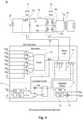
- Fig. 3shows a schematic block diagram of the generator 200 configured to output electrosurgical energy.
- the generator 200includes a controller 224, a power supply 227, and a radio-frequency (RF) amplifier 228.
- the power supply 227may be a high voltage, DC power supply connected to an AC source (e.g., line voltage) and provides high voltage, DC power to the RF amplifier 228 via leads 227a and 227b, which then converts high voltage, DC power into treatment energy (e.g., electrosurgical or microwave) and delivers the energy to the active terminal 230.
- treatment energye.g., electrosurgical or microwave
- the energyis returned thereto via the return terminal 232.
- the active and return terminals 230 and 232and coupled to the RF amplifier 228 through an isolation transformer 229.
- the RF amplifier 228is configured to operate in a plurality of modes, during which the generator 200 outputs corresponding waveforms having specific duty cycles, peak voltages, crest factors, etc. It is envisioned that in other disclosures, the generator 200 may be based on other types of suitable power supply topologies.
- the controller 224includes a processor 225 operably connected to a memory 226, which may include transitory type memory (e.g., RAM) and/or non-transitory type memory (e.g., flash media, disk media, etc.).
- the processor 225includes an output port that is operably connected to the power supply 227 and/or RF amplifier 228 allowing the processor 225 to control the output of the generator 200 according to either open and/or closed control loop schemes.
- a closed loop control schemeis a feedback control loop, in which a plurality of sensors measure a variety of tissue and energy properties (e.g., tissue impedance, tissue temperature, output power, current and/or voltage, etc.), and provide feedback to the controller 224.
- the controller 224then signals the power supply 227 and/or RF amplifier 228, which adjusts the DC and/or power supply, respectively.
- the processor 225may be substituted for by using any logic processor (e.g., control circuit) adapted to perform the calculations and/or set of instructions described herein including, but not limited to, field programmable gate array, digital signal processor, and combinations thereof.
- the generator 200includes a plurality of sensors 280, e.g., an RF current sensor 280a, and an RF voltage sensor 280b.
- Various components of the generator 200namely, the RF amplifier 228, the RF current and voltage sensors 280a and 280b, may be disposed on a printed circuit board (PCB).
- the RF current sensor 280ais coupled to the active terminal 230 and provides measurements of the RF current supplied by the RF amplifier 228.
- the RF voltage sensor 280bis coupled to the active and return terminals 230 and 232 provides measurements of the RF voltage supplied by the RF amplifier 228.
- the RF current and voltage sensors 280a and 280bmay be coupled to active and return leads 228a and 228b, which interconnect the active and return terminals 230 and 232 to the RF amplifier 228, respectively.
- the RF current and voltage sensors 280a and 280bprovide the sensed RF voltage and current signals, respectively, to the controller 224, which then may adjust output of the power supply 227 and/or the RF amplifier 228 in response to the sensed RF voltage and current signals.
- the controller 224also receives input signals from the input controls of the generator 200, the instrument 20 and/or forceps 30. The controller 224 utilizes the input signals to adjust power outputted by the generator 200 and/or performs other control functions thereon.
- Fig. 4shows another disclosure of the generator 200 configured to operate with near-deadbeat control to maintain a desired AC output of generator 200.
- deadbeator “near-deadbeat” refer to adjustments being made by the generator 200 to the output from about 1 cycle of the waveform to about 100 cycles, in disclosures from about 10 cycles to about 25 cycles.
- cyclerefers to a full cycle of an electrosurgical alternating waveform having a positive and negative half cycle.
- the generator 200may have an operating frequency of from about 100 kHz to about 1,000 kHz, and in certain embodiments, from about 200 kHz to about 500 kHz, thus the generator 200 operating at the predetermined frequency of 100 kHz outputs a waveform having 100,000 cycles per second.
- the adjustments to the outputcan be made at the same frequency (e.g., 1 cycle of the electrosurgical waveform) or a factor of about 0.1 (e.g., every 10 cycles of the electrosurgical waveform).
- near-deadbeat controlminimizes unintentional charring by ensuring that only a desired quantum of power is delivered to the electrosurgical instrument.
- slow transient response of the converter to changes in load impedancemay result in excessive delivery of power that may not be detected for 500 cycles or more.
- the generator 200is also configured to operate in any of a constant voltage limit mode, a constant current limit mode, a constant power mode, and combinations thereof.
- the mode selectionis generally based on the impedance associated with the tissue being cut. Different types of tissue, such as muscle and fat, have different impedances.
- constant power outputtends to uniformly vaporize tissue, resulting in clean dissection. Whereas constant voltage output tends to explosively vaporize or carbonize tissue ("black coagulation"), and constant current output tends to thermally coagulate tissue without vaporization (“white coagulation”). Carbonization is surgically useful if the surgeon wishes to rapidly destroy surface tissue, and thermal coagulation is regularly coupled with mechanical pressure to seal hepatic or lymphatic vessels shut. However, the surgeon generally desires to operate using constant power output and importantly, return to using constant power output as quickly as possible if there is deviation.
- constant poweris defined to mean the average power delivered in each switching cycle is substantially constant.
- constant voltage and constant currentare defined as modes where the root mean square (RMS) value of the AC voltage or current, respectively, is regulated to a substantially fixed value.
- RMSroot mean square
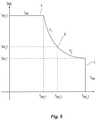
- An exemplary graphical representation of the desired output characteristicsis illustrated in Fig. 5 .
- the load impedanceincreases and voltage increases, the corresponding increasing output voltage triggers a transition from a constant current mode shown as region A to a constant power mode shown as region B and to a constant voltage mode shown as region C.
- the load impedancedecreases and current increases, the corresponding decreasing output voltage triggers the opposite transition from the constant voltage region C to the constant power region B and to the constant current region A.
- the generator 200includes a DC-DC buck converter 101, a DC-AC boost converter 102, an inductor 103, a transformer 104, and the controller 224.
- the DC-DC buck converter 101 and the DC-AC boost converter 102are part of the RF output stage 228.
- a DC voltage source Vgsuch as the power supply 227, is connected to DC-DC buck converter 101.
- inductor 103is electrically coupled between DC-DC buck converter 101 and DC-AC boost converter 102.
- the output of DC-AC boost converter 102transmits power to the primary winding of transformer 104, which passes through the secondary winding of transformer 104 to the load Z (e.g., tissue being treated).
- the DC-DC buck converter 101includes a switching element 101a and the DC-AC boost converter 102 includes a plurality of switching elements 102a-102d arranged in an H-bridge topology.
- the DC-AC boost converter 102may be configured according to any suitable topology including, but not limited to, half-bridge, full-bridge, push-pull, and the like.
- Suitable switching elementsinclude voltage-controlled devices such as transistors, field-effect transistors (FETs), combinations thereof, and the like.
- controller 224is in communication with both DC-DC buck converter 101 and DC-AC boost converter 102, in particular, the switching elements 101a and 102a-102d, respectively.
- the controller 224is configured to output control signals, which may be a pulse-width modulated signal, to the switching elements 101a and 102a-102d as described in further detail below with respect to the voltage-mode controller 112.
- the controller 224is configured to control the duty cycle d1 of the control signal supplied to the switching element 101a of the DC-DC buck converter 101 and the duty cycle d2 of the control signals supplied to the switching elements 102a-102d of the DC-AC boost converter 102.
- controller 224is configured to measure power characteristics of generator 200, and control generator 200 based at least in part on the measured power characteristics. Examples of the measured power characteristics include the current through inductor 103 and the voltage at the output of DC-AC boost converter 102.
- controller 224controls buck converter 101 by generating the duty cycle d1 based on a comparison of the inductor current and a nonlinear carrier control current for every cycle.
- controller 224includes a current-mode controller 111, a voltage-mode controller 112, a mode selector 113, and steering logic 114.
- the mode selector 113compares the output voltage V out (t) and the inductor current i L (t) to set limits in order to determine the desired mode of operation of the generator 200.
- the operational modemay be of constant (or maximum) current I max (e.g., constant current region A), constant power P 1 from DC-DC buck converter 101, constant power P 2 from DC-AC boost converter 102 (e.g., constant power region B), or constant (or maximum) voltage V max (e.g., constant voltage region C) as illustrated in Fig. 5 , or combinations thereof.
- steering logic 114controls which of at least one of current-mode controller 111 and voltage mode controller 112 are enabled. Furthermore, steering logic 114 selects which conversion stage receives the output of current-mode controller 111 and/or voltage-mode controller 112.
- steering logic 114switches between operating either DC-DC buck converter 101 or DC-AC boost converter 102 with current-mode control for constant power, depending on which portion of the desired output characteristics is being produced.
- the voltage mode controller 112 and/or current mode controller 111adjust the duty cycles d1 and/or d2 for current mode control.
- steering logic 114selects the duty cycle that each of DC-DC buck converter 101 and/or DC-AC boost converter 102 receives.
- the current-mode controller 111compares the inductor current i L (t) to nonlinear carrier control current i C (t) (e.g., desired set point current).
- the nonlinear carrier control current i Cis set by the selection of Pset (e.g., desired power set point), which may be done by a user, or provided by a lookup table.
- current-mode controller 111uses a latch circuit to compare inductor current i L (t) to either a current limit signal (I) or a power limit signal (P 1 ).
- the control signal for the latch circuitis the mode signal, which is communicated from steering logic 114.
- the inputs of the latch circuitare a clock signal and either the current limit signal (1) or a power limit signal (P 1 ).
- the selection of the current-mode controller 111 outputis in response to the current mode of the generator 200.
- the operating mode of the generator 200may be communicated by the mode selector 113.
- the switching waveform d(t)is switched "high” at the start of a switching period if the inductor current i L (t) is lower than nonlinear carrier control current i C (t).
- the switching waveform d(t)is switched "low” in response to the inductor current i L (t) exceeding the nonlinear carrier control current i C (t).
- a comparison of the inductor current i L (t) to nonlinear carrier control current i C (t)facilitates adjusting pulse duration of duty cycle d1 of the buck converter 101, as previously described.
- the average value of inductor current i L (t)is set to be substantially equal to fixed control current limit K ⁇ Pset.
- the current-mode controllerregulates the inductor current i L (t) to an approximately constant value, which is substantially equal to the fixed control current limit.
- the current-mode controller 111is able to maintain an approximately constant value of inductor current i L (t) by adjusting the current within from about 1 cycle to about 100 cycles, in disclosures from about 2 to about 20 cycles, in further embodiments, from about 3 to about 10 cycles. This low cycle adjustment provides for near-deadbeat or deadbeat control as described above.
- voltage-mode controller 112 of the controller 224includes a comparator 121, a compensator 122, and a pulse-width modulator (PWM) 123.
- voltage-mode controller 112compares the output voltage V out (t) with a reference voltage V max at comparator 121.
- the output of comparator 121is communicated to compensator 122, which in turn, outputs an error signal that drives PWM 123.
- the output of compensator 122is passed through PWM 123, which sets the duty cycle d2 of the signal in certain modes.
- mode selector 113includes an encoder and performs multiple comparisons. With respect to Fig. 5 , the mode selector 113 uses the voltage comparison signals and the current comparison signals to determine whether generator 200 is operating in the constant current output region (A), the region P1 of the constant power output region (B), the region P2 of the constant power output region (B), or the constant voltage output region (C). Furthermore, the output mode signal from mode selector 113 controls the switch position in steering logic 114. When output voltage V out (t) exceeds the first voltage limit V limit_1 , the second voltage limit V limit_2 , and the third voltage limit V iimit_3 , then the encoder selects the constant voltage mode.
- the constant voltage mode signal from mode selector 113causes the position of the switches of steering logic 114 to a "V" position as illustrated in Fig. 4 and Table 1 below, which shows duty cycle of DC-DC buck converter 101 and DC-AC boost converter 102 by operating mode.
- the values "1"may be set to any fixed duty cycle below 100%.
- the selection of operating modesis based in part on the duty cycle. For example, if the generator 200 is operating in constant power mode using the DC-DC buck converter 101 and the duty cycle reaches 100% active, the controller 224 may be configured to switch to the constant power region A using the DC-AC boost converter 102. The switch to the boost converter enables the generator 200 to operate over a higher range of impedances.
- constant AC power outputis achieved by setting one or both of duty cycle d1 and duty cycle d2 to desired values.
- generator 200operates with constant AC power output in either a first constant power region P1 or a second constant power region P2.
- the converterswitches of the steering logic 114 between generating constant power using DC-DC buck converter 101 or DC-AC boost converter 102, depending on the impedance of the load.
- generator 200may operate both DC-DC buck converter 101 and/or DC-AC boost converter 102 at the same time, which results in a constant power output having a high voltage and low power.
- inductor current i L (t)is compared to a nonlinear carrier control current i C (t) in current-mode controller 111.
- the pulse duration of the duty cycle d1 of the DC-DC buck converteris varied using the current mode controller 111.
- the varying pulse duration of the duty cyclecontrols the inductor current i L (t), which is responsive to the load in contact with the buck converter.
- the impedance of the loadvaries, the voltage across and the current through the inductor 103 also vary.
- the active portion of the duty cycleis initiated. In response to the inductor feedback signal exceeding the nonlinear carrier control current, the duty cycle switches to the non-active portion.
- the duty cyclestays in the non-active portion until the end of the duty cycle, upon which the next duty cycle begins in the active portion.
- generator 200generates constant power using DC-DC buck converter 101.
- the average voltage of V 1 (t)is constant in response to the input voltage Vg being constant, the DC-DC buck converter 101 is also disabled, since there is no voltage across inductor 103.
- the use of current programmed mode controlresults in the average current of i L (t) being regulated to an approximately fixed value with deadbeat or near-deadbeat control.
- duty cycle d2is varied by the current mode controller to maintain i L (t) at a fixed value.
- the power at input of DC-AC boost converter 102is also constant.
- the DC-AC boost converter 102is nearly lossless, resulting in the output power being approximately equal to the input power. Since the input power is constant, the output power of DC-AC boost converter 102 is also constant.
- constant voltage outputis achieved by setting duty cycle d1 of DC-DC buck converter 101 to a fixed value, and duty cycle d2 of DC-AC boost converter 102 is voltage-mode controlled.
- the voltage-mode controlinvolves measuring the output voltage of DC-AC boost converter 102 with a sensor network, feeding the sensed output voltage to a control loop in voltage-mode controller 112, and adjusting the converter's duty cycle command based on the relative difference between the measured output voltage and the reference output voltage.
- the duty cycle d2is set to increase or decrease the output voltage to match V limit .
- V limitmay be set by a user or based on values in a look-up table.
- the boost inverteris run at a fixed duty cycle with no feedback of the output voltage.
- constant current outputis achieved by operating DC-AC boost converter 102 at a fixed duty cycle d2 and current-mode controlling DC-DC buck converter 101.
- the current-mode controlaccurately controls the average inductor current such that the output of buck converter 101 is a constant current.
- current-mode controller 111compares inductor current i L (t) to a constant current i c , which is set by K ⁇ Pset, where K ⁇ Pset is a constant current set by the user during use. In various embodiments, Pset is set during the design stage.
- controller 224is configured to vary duty cycle d1 in order to maintain inductor current i L (t) at the fixed value.
- the constant current output modeproduces an AC output current whose magnitude is regulated with near-deadbeat speed.
- the generator 200 implementing the three modes of constant power, constant voltage, or constant currentproduces a very fast, very accurate regulation of the AC output characteristic.
- controller 224may switch between operating modes based in part on monitored characteristics, such as inductor current and voltage.
- the controller 224performs near deadbeat control by regulating inductor current to an approximately constant value, equal to a reference current.
- Transitioning between the three modesis determined by monitoring the voltage of the primary winding of transformer 104 and the inductor current. Furthermore, the determination of transitioning between the modes is also based on the voltage and current of inductor 103.
- the controller 224transitions modes from constant current to constant power to constant voltage as the output voltage increases. Specifically, in an exemplary disclosure, the generator 200 operates in the constant current mode if the output voltage is less than a first voltage limit (V limit_1 ). If the output voltage exceeds the first voltage limit, the generator 200 transitions to a first constant power mode (PI). If the output voltage exceeds a second voltage limit (V limit_2 ), the generator 200 transitions to a second constant power mode (P2).
- V limit_3If the output voltage exceeds a third voltage limit (V limit_3 ), the generator 200 transitions to the constant voltage mode, where the output voltage is limited and held constant.
- the first voltage limit (V limit_1 ), the second voltage limit (V limit_2 ), and the third voltage limit (V limit_3 )are set by a user or by the generator 200 (e.g., from a look-up table).
- an exemplary controller 224transitions from constant voltage mode to constant power mode and to constant current mode as inductor current i L (t) increases.
- the generator 200operates in the constant voltage mode if the inductor current does not exceed a first current limit (I limit_1 ). If the inductor current does exceed the first current limit (I limit_1 ), then the mode transitions to the second constant power mode (P2). If the inductor current exceeds a second current limit (I limit_2 ), then the mode transitions to the first constant power mode (P1). If the inductor current exceeds a third current limit (I limit_3 ), the generator 200 transitions to the constant current mode, where the inductor current is limited and held constant.
- the first current limit (I limit_1 ), the second current limit (I limit_2 ), and the third current limit (I limit_3 )are set by a user or by the generator (e.g., from a look-up table).
- the DC-DC buck converter 101is controlled in current-program mode (CPM) and the DC-AC boost converter 102 is fixed at about 100% duty cycle d2.
- CPMcurrent-program mode
- the DC-DC buck converter 101is controlled in non-linear carrier control (NLC) mode and the DC-AC boost converter 102 is fixed at about 100% duty cycle d2.
- NLCnon-linear carrier control
- the DC-DC buck converter 101is fixed at about 100% duty cycle d1 and the DC-AC boost converter 102 is controlled in CPM.
- the DC-DC buck converter 101is fixed at 100% duty cycle d1 and the DC-AC boost converter 102 is fixed at a predetermined duty cycle d2, which may be less than 100%.
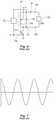
- certain conventional electrosurgicalinclude resonant networks that generate sinusoidal waveforms as disclosed in U.S. Patent No. 5,438,302 .
- a prior art electrosurgical generator 300includes an oscillator with a MOSFET oscillator device 310 coupled in series with a resonant output network 312 between a positive voltage supply rail V+ and a ground.
- the resonant network 312has an inductor configured as an autotransformer 314 with a parallel tuning capacitance 316 coupled across the complete winding and a pair of output terminals 318a, 318b, which are connected to an electrosurgical load 324 (e.g., tissue) as shown in Fig. 7 .
- the terminal 318ais isolated from the transformer 314 and parallel capacitor 316 by a series coupling capacitor 320.
- One portion of the transformer secondary windingacts as a primary winding 314p which is coupled between the supply V+ and the drain terminal of the MOSFET 310.
- a feedback circuit 322links one end of the secondary winding to a gate terminal 310g of the MOSFET 310.
- the generator 300also includes a capacitor that provides a feedback voltage to the gate terminal 310g. Voltage applied to the gate terminal 310g of the MOSFET 310 drives the MOSFET 310 between the fully “on” and fully “off” states, such that the resonant network 312 generates a sinusoidal waveform across the secondary winding.
- the voltage supplied to the MOSFET 310may be modulated to generate waveforms having a variable crest factor.
- crest factordenotes a ratio of peak voltage to RMS voltage. Crest factor is directly related to the tissue effects applied to tissue. Higher crest factors result in long, high-energy arcs applied to the tissue, which increase coagulation effects. Low crest factor result in lower energy arcs useful in increasing cutting effects. Voltage applied to the gate terminal 310g is of fixed carrier frequency that is modulated to achieve a desired crest factor setting. Thus, a fixed carrier frequency is modulated at a second, modulation frequency, to achieve a waveform having a desired duty cycle/crest factor.
- the fixed carrier frequencymay be from about 100 kHz to about 1,000 kHz, and in certain disclosures, from about 200 kHz to about 500 kHz.
- the modulating frequencymay be from about 5 kHz to about 50 kHz, in certain embodiments from about 10 kHz to about 40 kHz.
- a duty cycle of the fixed carrier frequency signalis adjusted to obtain a desired crest factor, since varying the duty cycle varies the RMS, which in turn affects the crest factor.
- Fig. 8the modulation of the fixed carrier signal is illustrated, which shows a modulated waveform having higher crest factor waveforms by lowering the duty cycle (e.g., two cycles ON, three cycles OFF).
- the generator 200is capable of outputting electrosurgical waveforms having any user-settable crest factor, such that the waveforms have an infinitely variable crest factor which may be adjusted on a cycle-by-cycle basis.
- the duty cyclemay be adjusted manually, e.g., by the user, or automatically, e.g., by the generator 200, in response to energy delivery feedback or any other suitable parameter, e.g., time, as described in further detail below.
- the generator 200includes the DC-AC boost converter 102 that is directly coupled to the transformer 104, which is in turn coupled directly to the patient via electrosurgical instrument 20 and/or forceps 30.
- the generator 200does not include any resonant circuit coupled between the boost converter 102 and the transformer 104, which allows for generation of square electrosurgical waveforms as shown in Figs. 9-11 .
- the generator 200is configured to generate a waveform having a plurality of cycles with varying cycle lengths (e.g., duty cycle) and peak voltages, while maintaining the root mean square voltage, thus the power being supplied is unchanged. Variations in the peak voltage of each of the cycles also vary the crest factor for each of the cycles, allowing for cycle-by-cycle crest factor adjustments. Adjustments to the peak voltage are accomplished by the DC-DC buck converter 101, namely, by adjusting the duty cycle d1 of the control signal supplied to the switching element 101a of the DC-DC buck converter 101. Adjustments to the length of the RF cycles are accomplished at the DC-AC boost converter 102. In particular, the controller 224 adjusts the duty cycle d2 of the control signals supplied to the switching elements 102a-102d of the DC-AC boost converter 102.
- cycle lengthse.g., duty cycle
- the crest factor of the waveformcan be varied to any arbitrary value as well.
- waveforms with any desirable crest factorcan be produced with the value of the crest factor being continuously adjustable, such as those shown in Figs. 10 and 11 .
- the generator 200may include discrete crest factor settings, which may be input via the user interface 241. With reference to Fig. 10 , a non-modulated electrosurgical waveform having a discrete crest factor is shown. In further disclosures, the generator 200 may include an input for continuously varying the crest factor. The user interface 241 may include a setting to adjust the crest factor. In further disclosures, electrosurgical instrument 20 and/or forceps 30 or other input devices (e.g., foot switch) may include inputs to adjust the crest factor. In additional disclosures, the crest factor may be adjusted by the controller 224 automatically based on changes in energy and/or tissue properties (e.g., impedance).
- tissue propertiese.g., impedance
- the generator 200may measure any suitable energy and/or tissue parameter using the sensors 280 including, but not limited to, voltage, current, phase, impedance, arc luminosity, arc length, temperature, force exerted on the instrument, and combinations thereof and automatically adjust the crest factor in response to this measurement.
- Fig. 11shows an electrosurgical waveform having varying cycle width, thereby changing the crest factor, while maintaining the same power due to the change in peak voltage based on varying crest factor input.
Landscapes
- Health & Medical Sciences (AREA)
- Surgery (AREA)
- Engineering & Computer Science (AREA)
- Life Sciences & Earth Sciences (AREA)
- Biomedical Technology (AREA)
- Molecular Biology (AREA)
- Nuclear Medicine, Radiotherapy & Molecular Imaging (AREA)
- Plasma & Fusion (AREA)
- Physics & Mathematics (AREA)
- Heart & Thoracic Surgery (AREA)
- Medical Informatics (AREA)
- Otolaryngology (AREA)
- Animal Behavior & Ethology (AREA)
- General Health & Medical Sciences (AREA)
- Public Health (AREA)
- Veterinary Medicine (AREA)
- Surgical Instruments (AREA)
- Dc-Dc Converters (AREA)
Description
- The present disclosure relates to an electrosurgical system for operating an electrosurgical generator. More particularly, the present disclosure relates to a system, for adjusting crest factor of electrosurgical waveforms generated by an electrosurgical generator having a DC-DC buck converter and a DC-AC boost converter.
- Electrosurgery involves application of high radio frequency electrical current to a surgical site to cut, ablate, or coagulate tissue. In monopolar electrosurgery, a source or active electrode delivers radio frequency alternating current from the electrosurgical generator to the targeted tissue. A patient return electrode is placed remotely from the active electrode to conduct the current back to the generator.
- In bipolar electrosurgery, return and active electrodes are placed in close proximity to each other such that an electrical circuit is formed between the two electrodes (e.g., in the case of an electrosurgical forceps). In this manner, the applied electrical current is limited to the body tissue positioned between the electrodes. Accordingly, bipolar electrosurgery generally involves the use of instruments where it is desired to achieve a focused delivery of electrosurgical energy between two electrodes positioned on the instrument, e.g. forceps or the like. A forceps is a pliers-like instrument which relies on mechanical action between its jaws to grasp, clamp and constrict vessels or tissue. Electrosurgical forceps (open or endoscopic) utilize mechanical clamping action and electrical energy to effect hemostasis on the clamped tissue. The forceps include electrosurgical conductive surfaces which apply the electrosurgical energy to the clamped tissue. By controlling the intensity, frequency and duration of the electrosurgical energy applied through the conductive plates to the tissue, the surgeon can coagulate, cauterize and/or seal tissue. However, the above example is for illustrative purposes only and there are many other known bipolar electrosurgical instruments which are within the scope of the present disclosure.
- Electrosurgical procedures outlined above may utilize various tissue and energy parameters in a feedback-based control system. There is continual need to improve delivery of energy to the tissue.
- Documents cited during prosecution include
US 6,059,781 ,GB2132893 EP2353533 ,EP1849425 ,EP2469699 ,EP2100566 andUS2009209956 . - According to the invention the present disclosure provides for an electrosurgical generator. The electrosurgical generator includes: a non-resonant radio frequency output stage configured to output a substantially square electrosurgical waveform; and a controller coupled to the non-resonant radio frequency output stage, the controller configured to adjust a crest factor of the substantially square electrosurgical waveform on a cycle-by-cycle basis.
- In a disclosure the controller is configured to adjust the duty cycle and/or the peak voltage of the substantially square electrosurgical waveform to adjust the crest factor.
- In a disclosure the controller is configured to adjust the crest factor yet maintain the root mean square voltage of the substantially square electrosurgical waveform.
- In a disclosure the controller is configured to adjust the crest factor, yet maintain the output power of the substantially square electrosurgical waveform.
- In a disclosure the controller is able to adjust the crest factor of each cycle of the substantially square electrosurgical waveform.
- In a disclosure the generator is configured to allow and generate a continuously variable crest factor of the substantially square electrosurgical waveform. In an embodiment, the continuously variable crest factor is user settable.
- According to the invention the non-resonant radio frequency output stage further includes: a DC-DC buck converter configured to output a DC waveform, the DC-DC buck converter including at least one first switching element operated at a first duty cycle. In an embodiment, the controller comprises a current mode controller configured to compare a measured current to a constant control current in a constant current mode of operation of the generator and to a non-linear control current in a constant power mode of operation of the generator using a latch circuit to adjust the first duty cycle.
- According to the invention the non-resonant radio frequency output stage further includes: a DC-AC boost converter coupled to the DC-DC buck converter and including at least one second switching element operated at a second duty cycle, the DC-AC boost converter configured to convert the DC waveform to generate the substantially square electrosurgical waveform. In a disclosure the controller comprises a voltage mode controller configured to set the second duty cycle based on a comparison of output voltage and a constant reference voltage in a constant voltage mode of operation of the generator. In a disclosure the controller comprises a current mode controller (e.g. the aforementioned current mode controller) that is configured to compare a measured current to a constant control current in a constant power mode of operation of the generator to adjust the second duty cycle. In a disclosure an inductor is electrically coupled between the converters and the measured current is the inductor current.
- According to the invention, the controller is coupled to the DC-DC buck converter and the DC-AC boost converter and the controller is further configured to adjust the first duty cycle and the second duty cycle to adjust the duty cycle of the substantially square electrosurgical waveform. In a disclosure one of the first duty cycle and the second duty cycle is adaptively adjusted based on output voltage or current feedback and the other is kept constant in a set mode of operation of the generator. In a disclosure the controller includes a mode selector, the mode selector configured to compare output voltage and/or a measured current (such as an inductor current) to set limits in order to determine the desired mode of operation of the generator from at least two of the following modes: constant (or maximum current) controlled by adjusting the first duty cycle provided to control the DC-DC buck converter, constant power, constant power controlled by adjusting the second duty cycle provided to control the DC-AC boost converter, or constant (or maximum) voltage controlled by adjusting the second duty cycle provided to control the DC-AC boost converter.
- According to one embodiment of the invention, the first duty cycle adjusts a peak voltage of each cycle of the substantially square electrosurgical waveform.
- According to one embodiment of the invention the second duty cycle adjusts a duty cycle of the substantially square electrosurgical waveform.
- According to one embodiment of the invention generator includes a user input for selecting a desired crest factor and the controller is configured to adjust the first and second duty cycles in response to the desired crest factor.
- In a disclosure, the generator comprises an electrosurgical waveform output stage comprising the converters and a transformer coupled to receive the square electrosurgical waveform and to output the electrosurgical waveform.
- According to the invention the present disclosure provides for an electrosurgical generator. The electrosurgical generator includes: a DC-DC buck converter configured to output a DC waveform, the DC-DC buck converter including at least one first switching element operated at a first duty cycle; a DC-AC boost converter coupled to the DC-DC buck converter and including at least one second switching element operated at a second duty cycle, the DC-AC boost converter configured to convert the DC waveform to generate a substantially square electrosurgical waveform; and a controller coupled to the DC-DC buck converter and the DC-AC boost converter and configured to adjust the first duty cycle and the second duty cycle to adjust a crest factor of the substantially square electrosurgical waveform on a cycle-by-cycle basis.
- According to one aspect of the invention, the first duty cycle adjusts a voltage of each cycle of the substantially square electrosurgical waveform.
- According to one aspect of the invention, wherein the second duty cycle adjusts a duty cycle of the substantially square electrosurgical waveform.
- According to one aspect of the invention, the generator includes a user input for selecting a desired crest factor and the controller is configured to adjust the first and second duty cycles in response to the desired crest factor.
- According to another embodiment, the present disclosure provides for an electrosurgical generator including a DC-DC buck converter configured to output a DC waveform, the DC-DC buck converter including at least one first switching element operated at a first duty cycle; a DC-AC boost converter coupled to the DC-DC buck converter and including at least one second switching element operated at a second duty cycle, the DC-AC boost converter configured to convert the DC waveform to generate a substantially square electrosurgical waveform; and a controller coupled to the DC-DC buck converter and the DC-AC boost converter and configured to adjust the first duty cycle and the second duty cycle to adjust an output electrosurgical waveform of the generator. In an embodiment, a crest factor of the substantially square electrosurgical waveform is adjusted, on a cycle-by-cycle basis.
- In aspects of the disclosure, the controller is configured to control the buck converter by generating the first duty cycle based on a comparison of an inductor current in an inductor electrically coupled between the buck converter and the boost converter and a nonlinear carrier control current (e.g. a desired setpoint current) or a fixed control current.
- According to another aspect of the disclosure the controller uses a latch circuit to compare the inductor current to either the fixed control current or a power limit signal associated with the nonlinear carrier control current.
- According to another aspect of the above disclosure the controller is configured to switch at least one of the first and second duty cycles "high" at the start of a switching period if a measured current (e.g. an inductor current of an inductor electrically coupled between the buck converter and the boost converter) is lower than a control current, or switch this duty cycle "low" in response to the measured current (e.g. inductor current) exceeding the nonlinear carrier control current.
- In aspects of the various disclosures including the converters, the controller is configured to operate a constant current output mode of the generator, wherein the first duty cycle is adjusted based on a comparison of a measured current and a fixed control current and the second duty cycle is kept constant.
- In aspects of the various disclosures including the converters, the controller is configured to generate a first constant power output mode of the generator, wherein the first duty cycle is adjusted based on a comparison of a measured current and a non-linear setpoint control current and the second duty cycle is kept constant.
- In aspects of the various disclosures including the converters, the controller is configured to operate a second constant power mode, wherein second duty cycle is adjusted based on a comparison of a measured current and a fixed control current and the first duty cycle is kept constant.
- In aspects of the various disclosures including the converters, the controller is configured to operate a constant voltage output mode of the generator, wherein the second duty cycle is adjusted based on a comparison of output voltage and a fixed reference voltage and the first duty cycle is kept constant.
- In aspects, the first constant power mode is set by the controller to operate at lower load impedances or output voltages or higher output currents than the second constant power mode.
- In aspects, the controller is configured to set the constant current mode at lower load impedances or output voltages or higher output currents than the first constant power mode.
- In aspects, the constant voltage mode is set by the controller to operate at higher load impedances or output voltages or lower output currents than the second constant power mode.
- Various embodiments of the present disclosure are described herein with reference to the drawings wherein:
Fig. 1 is a perspective view of the components of one illustrative embodiment of an electrosurgical system according to the present disclosure;Fig. 2 is a front view of one embodiment of an electrosurgical generator according to the present disclosure;Fig. 3 is a schematic, block diagram of the embodiment of an electrosurgical generator ofFig. 2 according to the present disclosure;Fig. 4 is a schematic, block diagram of a DC-DC converter and a DC-AC inverter of the electrosurgical generator ofFig. 2 according to the present disclosure;Fig. 5 is a graphical representation of desired output characteristics according to the present disclosure;Fig. 6 is a schematic, block diagram of a prior art electrosurgical generator having a resonant circuit;Fig. 7 is a graphical representation of a prior art sinusoidal electrosurgical waveform;Fig. 8 is a graphical representation of a prior art sinusoidal electrosurgical waveform having a modulated duty cycle;Fig. 9 is a graphical representation of a square electrosurgical waveform output by the electrosurgical generator ofFig. 2 according to the present disclosure;Fig. 10 is a graphical representation of a square electrosurgical waveform having a uniform crest factor output by the electrosurgical generator ofFig. 2 according to the present disclosure; andFig. 11 is a graphical representation of a square electrosurgical waveform having a varying crest factor output by the electrosurgical generator ofFig. 2 according to the present disclosure.- Particular embodiments of the present disclosure are described herein below with reference to the accompanying drawings. In the following description, well-known functions or constructions are not described in detail to avoid obscuring the present disclosure in unnecessary detail.
- A generator according to the present disclosure can perform monopolar and/or bipolar electrosurgical procedures, including, for example, cutting, coagulation, ablation, and vessel sealing procedures. The generator may include a plurality of outputs for interfacing with various electrosurgical instruments (e.g., a monopolar instrument, return electrode, bipolar electrosurgical forceps, footswitch, etc.). Further, the generator includes electronic circuitry configured to generate radio frequency energy specifically suited for various electrosurgical modes (e.g., cut, blend, coagulate, division with hemostasis, fulgurate, spray, etc.) and procedures (e.g., monopolar, bipolar, vessel sealing). In disclosures the generator may be embedded, integrated or otherwise coupled to the electrosurgical instruments providing for an all-in-one electrosurgical apparatus.
Fig. 1 is a perspective view of the components of one illustrative disclosure of a bipolar and monopolarelectrosurgical system 10 according to the present disclosure. Thesystem 10 may include one or more monopolarelectrosurgical instruments 20 having one or more active electrodes 23 (e.g., electrosurgical cutting probe, ablation electrode(s), etc.) for treating tissue of a patient. Electrosurgical alternating current is supplied to theinstrument 20 by agenerator 200 via asupply line 24 that is connected to an active terminal 230 (Fig. 3 ) of thegenerator 200, allowing theinstrument 20 to cut, coagulate, ablate and/or otherwise treat tissue. The alternating current is returned to thegenerator 200 through areturn electrode pad 26 via areturn line 28 at a return terminal 32 (Fig. 3 ) of thegenerator 200. For monopolar operation, thesystem 10 may include a plurality ofreturn electrode pads 26 that, in use, are disposed on a patient to minimize the chances of tissue damage by maximizing the overall contact area with the patient. In addition, thegenerator 200 and thereturn electrode pads 26 may be configured for monitoring tissue-to-patient contact to ensure that sufficient contact exists therebetween.- The
system 10 may also include one or more bipolar electrosurgical instruments, for example, a bipolarelectrosurgical forceps 30 having one or more electrodes for treating tissue of a patient. Theelectrosurgical forceps 30 includes ahousing 31 and opposingjaw members shaft 32. Thejaw members active electrodes 34 and areturn electrode 36 disposed therein, respectively. Theactive electrode 34 and thereturn electrode 36 are connected to thegenerator 200 throughcable 38 that includes the supply and returnlines terminals Fig. 3 ). Theelectrosurgical forceps 30 is coupled to thegenerator 200 at a connector having connections to the active and returnterminals 230 and 232 (e.g., pins) via a plug disposed at the end of thecable 38, wherein the plug includes contacts from the supply and returnlines - With reference to
Fig. 2 , afront face 240 of thegenerator 200 is shown. Thegenerator 200 may be any suitable type (e.g., electrosurgical, microwave, etc.) and may include a plurality of connectors 250-262 to accommodate various types of electrosurgical instruments (e.g.,electrosurgical forceps 30, etc.). - The
generator 200 includes auser interface 241 having one or more display screens orinformation panels screens generator 200 includes suitable input controls (e.g., buttons, activators, switches, touch screen, etc.) for controlling thegenerator 200. The display screens 242, 244, 246 are also configured as touch screens that display a corresponding menu for the electrosurgical instruments (e.g.,electrosurgical forceps 30, etc.). The user then adjusts inputs by simply touching corresponding menu options. Screen 242 controls monopolar output and the devices connected to theconnectors Connector 250 is configured to couple to a monopolar electrosurgical instrument (e.g., electrosurgical instrument 20) andconnector 252 is configured to couple to a foot switch (not shown). The foot switch provides for additional inputs (e.g., replicating inputs of the generator 200).Screen 244 controls monopolar and bipolar output and the devices connected to theconnectors Connector 256 is configured to couple to other monopolar instruments.Connector 258 is configured to couple to a bipolar instrument (not shown).Screen 246 controls bipolar sealing procedures performed by theforceps 30 that may be plugged into theconnectors generator 200 outputs energy through theconnectors forceps 30. In particular,screen 246 outputs a user interface that allows the user to input a user-defined intensity setting. The user-defined setting may be any setting that allows the user to adjust one or more energy delivery parameters, such as power, current, voltage, energy, etc. or sealing parameters, such as energy rate limiters, sealing duration, etc. The user-defined setting is transmitted to thecontroller 224 where the setting may be saved inmemory 226. In disclosures, the intensity setting may be a number scale, such as for example, from one to ten or one to five. In disclosures, the intensity setting may be associated with an output curve of thegenerator 200. The intensity settings may be specific for eachforceps 30 being utilized, such that various instruments provide the user with a specific intensity scale corresponding to theforceps 30.Fig. 3 shows a schematic block diagram of thegenerator 200 configured to output electrosurgical energy. Thegenerator 200 includes acontroller 224, apower supply 227, and a radio-frequency (RF)amplifier 228. Thepower supply 227 may be a high voltage, DC power supply connected to an AC source (e.g., line voltage) and provides high voltage, DC power to theRF amplifier 228 vialeads active terminal 230. The energy is returned thereto via thereturn terminal 232. The active and returnterminals RF amplifier 228 through an isolation transformer 229. TheRF amplifier 228 is configured to operate in a plurality of modes, during which thegenerator 200 outputs corresponding waveforms having specific duty cycles, peak voltages, crest factors, etc. It is envisioned that in other disclosures, thegenerator 200 may be based on other types of suitable power supply topologies.- The
controller 224 includes aprocessor 225 operably connected to amemory 226, which may include transitory type memory (e.g., RAM) and/or non-transitory type memory (e.g., flash media, disk media, etc.). Theprocessor 225 includes an output port that is operably connected to thepower supply 227 and/orRF amplifier 228 allowing theprocessor 225 to control the output of thegenerator 200 according to either open and/or closed control loop schemes. A closed loop control scheme is a feedback control loop, in which a plurality of sensors measure a variety of tissue and energy properties (e.g., tissue impedance, tissue temperature, output power, current and/or voltage, etc.), and provide feedback to thecontroller 224. Thecontroller 224 then signals thepower supply 227 and/orRF amplifier 228, which adjusts the DC and/or power supply, respectively. Those skilled in the art will appreciate that theprocessor 225 may be substituted for by using any logic processor (e.g., control circuit) adapted to perform the calculations and/or set of instructions described herein including, but not limited to, field programmable gate array, digital signal processor, and combinations thereof. - The
generator 200 according to the present disclosure includes a plurality ofsensors 280, e.g., an RFcurrent sensor 280a, and anRF voltage sensor 280b. Various components of thegenerator 200, namely, theRF amplifier 228, the RF current andvoltage sensors current sensor 280a is coupled to theactive terminal 230 and provides measurements of the RF current supplied by theRF amplifier 228. TheRF voltage sensor 280b is coupled to the active and returnterminals RF amplifier 228. In disclosures, the RF current andvoltage sensors terminals RF amplifier 228, respectively. - The RF current and
voltage sensors controller 224, which then may adjust output of thepower supply 227 and/or theRF amplifier 228 in response to the sensed RF voltage and current signals. Thecontroller 224 also receives input signals from the input controls of thegenerator 200, theinstrument 20 and/orforceps 30. Thecontroller 224 utilizes the input signals to adjust power outputted by thegenerator 200 and/or performs other control functions thereon. Fig. 4 shows another disclosure of thegenerator 200 configured to operate with near-deadbeat control to maintain a desired AC output ofgenerator 200. As used herein, the terms "deadbeat" or "near-deadbeat" refer to adjustments being made by thegenerator 200 to the output from about 1 cycle of the waveform to about 100 cycles, in disclosures from about 10 cycles to about 25 cycles. The term cycle refers to a full cycle of an electrosurgical alternating waveform having a positive and negative half cycle. Thegenerator 200 according to the present disclosure may have an operating frequency of from about 100 kHz to about 1,000 kHz, and in certain embodiments, from about 200 kHz to about 500 kHz, thus thegenerator 200 operating at the predetermined frequency of 100 kHz outputs a waveform having 100,000 cycles per second. The adjustments to the output can be made at the same frequency (e.g., 1 cycle of the electrosurgical waveform) or a factor of about 0.1 (e.g., every 10 cycles of the electrosurgical waveform). In accordance with an exemplary disclosure, near-deadbeat control minimizes unintentional charring by ensuring that only a desired quantum of power is delivered to the electrosurgical instrument. In the prior art generators, slow transient response of the converter to changes in load impedance may result in excessive delivery of power that may not be detected for 500 cycles or more.- The
generator 200 is also configured to operate in any of a constant voltage limit mode, a constant current limit mode, a constant power mode, and combinations thereof. The mode selection is generally based on the impedance associated with the tissue being cut. Different types of tissue, such as muscle and fat, have different impedances. In terms of electrosurgical operations, constant power output tends to uniformly vaporize tissue, resulting in clean dissection. Whereas constant voltage output tends to explosively vaporize or carbonize tissue ("black coagulation"), and constant current output tends to thermally coagulate tissue without vaporization ("white coagulation"). Carbonization is surgically useful if the surgeon wishes to rapidly destroy surface tissue, and thermal coagulation is regularly coupled with mechanical pressure to seal hepatic or lymphatic vessels shut. However, the surgeon generally desires to operate using constant power output and importantly, return to using constant power output as quickly as possible if there is deviation. - With respect to the AC output of the
generator 200 and in exemplary disclosures, "constant power" is defined to mean the average power delivered in each switching cycle is substantially constant. Likewise, "constant voltage" and "constant current" are defined as modes where the root mean square (RMS) value of the AC voltage or current, respectively, is regulated to a substantially fixed value. An exemplary graphical representation of the desired output characteristics is illustrated inFig. 5 . In an exemplary disclosure, as the load impedance increases and voltage increases, the corresponding increasing output voltage triggers a transition from a constant current mode shown as region A to a constant power mode shown as region B and to a constant voltage mode shown as region C. Similarly, in an exemplary disclosure, as the load impedance decreases and current increases, the corresponding decreasing output voltage triggers the opposite transition from the constant voltage region C to the constant power region B and to the constant current region A. - With reference to the schematic shown in
Fig. 4 , thegenerator 200 includes a DC-DC buck converter 101, a DC-AC boost converter 102, aninductor 103, atransformer 104, and thecontroller 224. In embodiments, the DC-DC buck converter 101 and the DC-AC boost converter 102 are part of theRF output stage 228. In the exemplary embodiment, a DC voltage source Vg, such as thepower supply 227, is connected to DC-DC buck converter 101. Furthermore,inductor 103 is electrically coupled between DC-DC buck converter 101 and DC-AC boost converter 102. The output of DC-AC boost converter 102 transmits power to the primary winding oftransformer 104, which passes through the secondary winding oftransformer 104 to the load Z (e.g., tissue being treated). - The DC-
DC buck converter 101 includes aswitching element 101a and the DC-AC boost converter 102 includes a plurality of switchingelements 102a-102d arranged in an H-bridge topology. In embodiments, the DC-AC boost converter 102 may be configured according to any suitable topology including, but not limited to, half-bridge, full-bridge, push-pull, and the like. Suitable switching elements include voltage-controlled devices such as transistors, field-effect transistors (FETs), combinations thereof, and the like. In an exemplary embodiment,controller 224 is in communication with both DC-DC buck converter 101 and DC-AC boost converter 102, in particular, theswitching elements controller 224 is configured to output control signals, which may be a pulse-width modulated signal, to theswitching elements mode controller 112. In particular, thecontroller 224 is configured to control the duty cycle d1 of the control signal supplied to theswitching element 101a of the DC-DC buck converter 101 and the duty cycle d2 of the control signals supplied to theswitching elements 102a-102d of the DC-AC boost converter 102. Additionally,controller 224 is configured to measure power characteristics ofgenerator 200, andcontrol generator 200 based at least in part on the measured power characteristics. Examples of the measured power characteristics include the current throughinductor 103 and the voltage at the output of DC-AC boost converter 102. In an exemplary disclosure,controller 224 controls buckconverter 101 by generating the duty cycle d1 based on a comparison of the inductor current and a nonlinear carrier control current for every cycle. - In accordance with an exemplary disclosure, ,
controller 224 includes a current-mode controller 111, a voltage-mode controller 112, amode selector 113, andsteering logic 114. Themode selector 113 compares the output voltage Vout(t) and the inductor current iL(t) to set limits in order to determine the desired mode of operation of thegenerator 200. The operational mode may be of constant (or maximum) current Imax (e.g., constant current region A), constant power P1 from DC-DC buck converter 101, constant power P2 from DC-AC boost converter 102 (e.g., constant power region B), or constant (or maximum) voltage Vmax (e.g., constant voltage region C) as illustrated inFig. 5 , or combinations thereof. The output selection ofmode selector 113 is communicated tosteering logic 114. In an exemplary disclosure, steeringlogic 114 controls which of at least one of current-mode controller 111 andvoltage mode controller 112 are enabled. Furthermore, steeringlogic 114 selects which conversion stage receives the output of current-mode controller 111 and/or voltage-mode controller 112. - In one exemplary disclosure, steering
logic 114 switches between operating either DC-DC buck converter 101 or DC-AC boost converter 102 with current-mode control for constant power, depending on which portion of the desired output characteristics is being produced. Thevoltage mode controller 112 and/orcurrent mode controller 111 adjust the duty cycles d1 and/or d2 for current mode control. Furthermore, steeringlogic 114 selects the duty cycle that each of DC-DC buck converter 101 and/or DC-AC boost converter 102 receives. - The current-
mode controller 111 compares the inductor current iL(t) to nonlinear carrier control current iC(t) (e.g., desired set point current). In an exemplary disclosure, the nonlinear carrier control current iC is set by the selection of Pset (e.g., desired power set point), which may be done by a user, or provided by a lookup table. In an exemplary disclosure, current-mode controller 111 uses a latch circuit to compare inductor current iL(t) to either a current limit signal (I) or a power limit signal (P1). The control signal for the latch circuit is the mode signal, which is communicated from steeringlogic 114. The inputs of the latch circuit are a clock signal and either the current limit signal (1) or a power limit signal (P1). The selection of the current-mode controller 111 output is in response to the current mode of thegenerator 200. The operating mode of thegenerator 200 may be communicated by themode selector 113. In an exemplary disclosure, the switching waveform d(t) is switched "high" at the start of a switching period if the inductor current iL(t) is lower than nonlinear carrier control current iC(t). Furthermore, in the exemplary disclosure, the switching waveform d(t) is switched "low" in response to the inductor current iL(t) exceeding the nonlinear carrier control current iC(t). In other words, a comparison of the inductor current iL(t) to nonlinear carrier control current iC(t) facilitates adjusting pulse duration of duty cycle d1 of thebuck converter 101, as previously described. - To generate and control a constant current from
generator 200, the average value of inductor current iL(t) is set to be substantially equal to fixed control current limit K∗Pset. For small inductor current ripple, in other words ΔiL << IL, the current-mode controller regulates the inductor current iL(t) to an approximately constant value, which is substantially equal to the fixed control current limit. In accordance with an exemplary disclosure, the current-mode controller 111 is able to maintain an approximately constant value of inductor current iL(t) by adjusting the current within from about 1 cycle to about 100 cycles, in disclosures from about 2 to about 20 cycles, in further embodiments, from about 3 to about 10 cycles. This low cycle adjustment provides for near-deadbeat or deadbeat control as described above. - In an exemplary disclosure and with continued reference to
Fig. 4 , voltage-mode controller 112 of thecontroller 224 includes acomparator 121, acompensator 122, and a pulse-width modulator (PWM) 123. In an exemplary disclosure, voltage-mode controller 112 compares the output voltage Vout(t) with a reference voltage Vmax atcomparator 121. The output ofcomparator 121 is communicated tocompensator 122, which in turn, outputs an error signal that drives PWM 123. In the exemplary disclosure, the output ofcompensator 122 is passed through PWM 123, which sets the duty cycle d2 of the signal in certain modes. - Furthermore, in an exemplary disclosure,
mode selector 113 includes an encoder and performs multiple comparisons. With respect toFig. 5 , themode selector 113 uses the voltage comparison signals and the current comparison signals to determine whethergenerator 200 is operating in the constant current output region (A), the region P1 of the constant power output region (B), the region P2 of the constant power output region (B), or the constant voltage output region (C). Furthermore, the output mode signal frommode selector 113 controls the switch position insteering logic 114. When output voltage Vout(t) exceeds the first voltage limit Vlimit_1, the second voltage limit Vlimit_2, and the third voltage limit Viimit_3, then the encoder selects the constant voltage mode. The constant voltage mode signal frommode selector 113 causes the position of the switches ofsteering logic 114 to a "V" position as illustrated inFig. 4 and Table 1 below, which shows duty cycle of DC-DC buck converter 101 and DC-AC boost converter 102 by operating mode. In table 1, the values "1" may be set to any fixed duty cycle below 100%.Table 1 Imax P1 P2 Vmax Buck Converter Current-programmed mode (CPM) controlled with fixed control current limit CPM controlled with non-linear carrier control limit 1 1 Boost Converter 1 1 CPM controlled with fixed control current limit Voltage mode controlled - In various alternative disclosures, the selection of operating modes is based in part on the duty cycle. For example, if the
generator 200 is operating in constant power mode using the DC-DC buck converter 101 and the duty cycle reaches 100% active, thecontroller 224 may be configured to switch to the constant power region A using the DC-AC boost converter 102. The switch to the boost converter enables thegenerator 200 to operate over a higher range of impedances. - With respect to constant power output mode, constant AC power output is achieved by setting one or both of duty cycle d1 and duty cycle d2 to desired values. Moreover,
generator 200 operates with constant AC power output in either a first constant power region P1 or a second constant power region P2. In various disclosures, the converter switches of thesteering logic 114 between generating constant power using DC-DC buck converter 101 or DC-AC boost converter 102, depending on the impedance of the load. Moreover, in various disclosures,generator 200 may operate both DC-DC buck converter 101 and/or DC-AC boost converter 102 at the same time, which results in a constant power output having a high voltage and low power. - In steady-state and operating in first constant power region PI, inductor current iL(t) is compared to a nonlinear carrier control current iC(t) in current-
mode controller 111. The pulse duration of the duty cycle d1 of the DC-DC buck converter is varied using thecurrent mode controller 111. The varying pulse duration of the duty cycle controls the inductor current iL(t), which is responsive to the load in contact with the buck converter. As the impedance of the load varies, the voltage across and the current through theinductor 103 also vary. As previously described, at the beginning of the duty cycle, the active portion of the duty cycle is initiated. In response to the inductor feedback signal exceeding the nonlinear carrier control current, the duty cycle switches to the non-active portion. The duty cycle stays in the non-active portion until the end of the duty cycle, upon which the next duty cycle begins in the active portion. In alternative disclosures, during the comparison of the inductor feedback signal and the nonlinear carrier control current, once the control current exceeds the inductor current, the duty cycle switches to the active portion. In accordance with the exemplary disclosure,generator 200 generates constant power using DC-DC buck converter 101. - In steady-state and operating in second constant power region P2, the average voltage of V1(t) is constant in response to the input voltage Vg being constant, the DC-
DC buck converter 101 is also disabled, since there is no voltage acrossinductor 103. The use of current programmed mode control results in the average current of iL(t) being regulated to an approximately fixed value with deadbeat or near-deadbeat control. In order to regulate iL(t), duty cycle d2 is varied by the current mode controller to maintain iL(t) at a fixed value. Given the fixed voltage and current, the power at input of DC-AC boost converter 102 is also constant. In an exemplary disclosure, , the DC-AC boost converter 102 is nearly lossless, resulting in the output power being approximately equal to the input power. Since the input power is constant, the output power of DC-AC boost converter 102 is also constant. - With respect to constant voltage output mode, constant voltage output is achieved by setting duty cycle d1 of DC-
DC buck converter 101 to a fixed value, and duty cycle d2 of DC-AC boost converter 102 is voltage-mode controlled. In an exemplary disclosure, the voltage-mode control involves measuring the output voltage of DC-AC boost converter 102 with a sensor network, feeding the sensed output voltage to a control loop in voltage-mode controller 112, and adjusting the converter's duty cycle command based on the relative difference between the measured output voltage and the reference output voltage. In other words, the duty cycle d2 is set to increase or decrease the output voltage to match Vlimit. In an exemplary disclosure, Vlimit may be set by a user or based on values in a look-up table. In an alternative embodiment, the boost inverter is run at a fixed duty cycle with no feedback of the output voltage. - With respect to constant current output mode, constant current output is achieved by operating DC-
AC boost converter 102 at a fixed duty cycle d2 and current-mode controlling DC-DC buck converter 101. In an exemplary disclosure, the current-mode control accurately controls the average inductor current such that the output ofbuck converter 101 is a constant current. In one constant current embodiment, current-mode controller 111 compares inductor current iL(t) to a constant current ic, which is set by K∗Pset, where K∗Pset is a constant current set by the user during use. In various embodiments, Pset is set during the design stage. - In other words,
controller 224 is configured to vary duty cycle d1 in order to maintain inductor current iL(t) at the fixed value. As a result, the constant current output mode produces an AC output current whose magnitude is regulated with near-deadbeat speed. In an exemplary disclosure, thegenerator 200 implementing the three modes of constant power, constant voltage, or constant current produces a very fast, very accurate regulation of the AC output characteristic. Various modes are impacted by monitored characteristics, while other modes do not need to respond to the same monitored characteristics. Specifically,controller 224 may switch between operating modes based in part on monitored characteristics, such as inductor current and voltage. In other words, the selection of which stage of the converter to current-mode control is achieved with minimal feedback and without a need for extraneous measurements, averaging, or feedback of the output. Also, and as previously mentioned, thecontroller 224 performs near deadbeat control by regulating inductor current to an approximately constant value, equal to a reference current. - Transitioning between the three modes, in an exemplary disclosure, is determined by monitoring the voltage of the primary winding of
transformer 104 and the inductor current. Furthermore, the determination of transitioning between the modes is also based on the voltage and current ofinductor 103. Thecontroller 224 transitions modes from constant current to constant power to constant voltage as the output voltage increases. Specifically, in an exemplary disclosure, thegenerator 200 operates in the constant current mode if the output voltage is less than a first voltage limit (Vlimit_1). If the output voltage exceeds the first voltage limit, thegenerator 200 transitions to a first constant power mode (PI). If the output voltage exceeds a second voltage limit (Vlimit_2), thegenerator 200 transitions to a second constant power mode (P2). If the output voltage exceeds a third voltage limit (Vlimit_3), thegenerator 200 transitions to the constant voltage mode, where the output voltage is limited and held constant. In an exemplary disclosure, the first voltage limit (Vlimit_1), the second voltage limit (Vlimit_2), and the third voltage limit (Vlimit_3) are set by a user or by the generator 200 (e.g., from a look-up table). - Similarly, an
exemplary controller 224 transitions from constant voltage mode to constant power mode and to constant current mode as inductor current iL(t) increases. Specifically, in an exemplary disclosure, thegenerator 200 operates in the constant voltage mode if the inductor current does not exceed a first current limit (Ilimit_1). If the inductor current does exceed the first current limit (Ilimit_1), then the mode transitions to the second constant power mode (P2). If the inductor current exceeds a second current limit (Ilimit_2), then the mode transitions to the first constant power mode (P1). If the inductor current exceeds a third current limit (Ilimit_3), thegenerator 200 transitions to the constant current mode, where the inductor current is limited and held constant. In an exemplary disclosure, the first current limit (Ilimit_1), the second current limit (Ilimit_2), and the third current limit (Ilimit_3) are set by a user or by the generator (e.g., from a look-up table). - As described above, in order to achieve the constant current region A, the DC-
DC buck converter 101 is controlled in current-program mode (CPM) and the DC-AC boost converter 102 is fixed at about 100% duty cycle d2. In order to achieve the constant power region B, in one embodiment the DC-DC buck converter 101 is controlled in non-linear carrier control (NLC) mode and the DC-AC boost converter 102 is fixed at about 100% duty cycle d2. In another disclosure, the DC-DC buck converter 101 is fixed at about 100% duty cycle d1 and the DC-AC boost converter 102 is controlled in CPM. In order to achieve the constant voltage region B, the DC-DC buck converter 101 is fixed at 100% duty cycle d1 and the DC-AC boost converter 102 is fixed at a predetermined duty cycle d2, which may be less than 100%. - With reference to
Figs. 6-8 , certain conventional electrosurgical include resonant networks that generate sinusoidal waveforms as disclosed inU.S. Patent No. 5,438,302 . - With reference to
Fig. 6 , a prior art electrosurgical generator 300 includes an oscillator with aMOSFET oscillator device 310 coupled in series with aresonant output network 312 between a positive voltage supply rail V+ and a ground. Theresonant network 312 has an inductor configured as anautotransformer 314 with aparallel tuning capacitance 316 coupled across the complete winding and a pair ofoutput terminals Fig. 7 . The terminal 318a is isolated from thetransformer 314 andparallel capacitor 316 by aseries coupling capacitor 320. One portion of the transformer secondary winding acts as a primary winding 314p which is coupled between the supply V+ and the drain terminal of theMOSFET 310. Afeedback circuit 322 links one end of the secondary winding to agate terminal 310g of theMOSFET 310. The generator 300 also includes a capacitor that provides a feedback voltage to thegate terminal 310g. Voltage applied to thegate terminal 310g of theMOSFET 310 drives theMOSFET 310 between the fully "on" and fully "off" states, such that theresonant network 312 generates a sinusoidal waveform across the secondary winding. The voltage supplied to theMOSFET 310 may be modulated to generate waveforms having a variable crest factor. - As used herein, the term "crest factor" denotes a ratio of peak voltage to RMS voltage. Crest factor is directly related to the tissue effects applied to tissue. Higher crest factors result in long, high-energy arcs applied to the tissue, which increase coagulation effects. Low crest factor result in lower energy arcs useful in increasing cutting effects. Voltage applied to the
gate terminal 310g is of fixed carrier frequency that is modulated to achieve a desired crest factor setting. Thus, a fixed carrier frequency is modulated at a second, modulation frequency, to achieve a waveform having a desired duty cycle/crest factor. - The fixed carrier frequency may be from about 100 kHz to about 1,000 kHz, and in certain disclosures, from about 200 kHz to about 500 kHz. The modulating frequency may be from about 5 kHz to about 50 kHz, in certain embodiments from about 10 kHz to about 40 kHz. In particular, a duty cycle of the fixed carrier frequency signal is adjusted to obtain a desired crest factor, since varying the duty cycle varies the RMS, which in turn affects the crest factor. With reference to
Fig. 8 , the modulation of the fixed carrier signal is illustrated, which shows a modulated waveform having higher crest factor waveforms by lowering the duty cycle (e.g., two cycles ON, three cycles OFF). - There are a number of drawbacks with this approach. The relatively low frequency of the modulating frequency is capable of stimulating muscle tissue. Thus, paralytic anesthesia is required to prevent this effect, although "muscle capture," e.g., stimulation of muscle by the electrosurgical generator is often still present. In addition, modulating a fixed carrier signal produces harmonics, which require significant design and manufacturing modifications associated with electrical noise suppression, filtering, interference with other systems (e.g., return electrode monitoring etc.). Further, conventional generators only include a discrete number of fixed crest factor settings associated with preset electrosurgical modes having "optimal" settings that provide desired tissue effects. However, a discrete number of fixed crest factor settings limits available tissue effects and requires that "optimal" settings be programmed into the generator.
- The
generator 200 according to the present disclosure is capable of outputting electrosurgical waveforms having any user-settable crest factor, such that the waveforms have an infinitely variable crest factor which may be adjusted on a cycle-by-cycle basis. In disclosures, the duty cycle may be adjusted manually, e.g., by the user, or automatically, e.g., by thegenerator 200, in response to energy delivery feedback or any other suitable parameter, e.g., time, as described in further detail below. - As discussed above, the
generator 200 includes the DC-AC boost converter 102 that is directly coupled to thetransformer 104, which is in turn coupled directly to the patient viaelectrosurgical instrument 20 and/orforceps 30. Thegenerator 200 does not include any resonant circuit coupled between theboost converter 102 and thetransformer 104, which allows for generation of square electrosurgical waveforms as shown inFigs. 9-11 . - With reference to
Fig. 9 , thegenerator 200 is configured to generate a waveform having a plurality of cycles with varying cycle lengths (e.g., duty cycle) and peak voltages, while maintaining the root mean square voltage, thus the power being supplied is unchanged. Variations in the peak voltage of each of the cycles also vary the crest factor for each of the cycles, allowing for cycle-by-cycle crest factor adjustments. Adjustments to the peak voltage are accomplished by the DC-DC buck converter 101, namely, by adjusting the duty cycle d1 of the control signal supplied to theswitching element 101a of the DC-DC buck converter 101. Adjustments to the length of the RF cycles are accomplished at the DC-AC boost converter 102. In particular, thecontroller 224 adjusts the duty cycle d2 of the control signals supplied to theswitching elements 102a-102d of the DC-AC boost converter 102. - Since the duty cycle and the peak voltage of the cycles of the resulting waveforms can be varied to any arbitrary interval, the crest factor of the waveform can be varied to any arbitrary value as well. Thus, waveforms with any desirable crest factor can be produced with the value of the crest factor being continuously adjustable, such as those shown in
Figs. 10 and 11 . - In disclosures, the
generator 200 may include discrete crest factor settings, which may be input via theuser interface 241. With reference toFig. 10 , a non-modulated electrosurgical waveform having a discrete crest factor is shown. In further disclosures, thegenerator 200 may include an input for continuously varying the crest factor. Theuser interface 241 may include a setting to adjust the crest factor. In further disclosures,electrosurgical instrument 20 and/orforceps 30 or other input devices (e.g., foot switch) may include inputs to adjust the crest factor. In additional disclosures, the crest factor may be adjusted by thecontroller 224 automatically based on changes in energy and/or tissue properties (e.g., impedance). In particular, thegenerator 200 may measure any suitable energy and/or tissue parameter using thesensors 280 including, but not limited to, voltage, current, phase, impedance, arc luminosity, arc length, temperature, force exerted on the instrument, and combinations thereof and automatically adjust the crest factor in response to this measurement.Fig. 11 , shows an electrosurgical waveform having varying cycle width, thereby changing the crest factor, while maintaining the same power due to the change in peak voltage based on varying crest factor input. - Using continuous, rather than modulated, waveforms to achieve higher crest factors allows for reduction in muscle stimulation generated during electrosurgical energy. Additionally, design and manufacturing challenges associated with filtering and electrical noise generated through the modulation process are significantly reduced. Finally, the ability to arbitrarily and continuously adjust the crest factor of an electrosurgical waveform presents the opportunity to achieve novel new tissue effects, improve surgeon control, and achieve the desired tissue result.
- While several embodiments of the disclosure have been shown in the drawings and/or described herein, it is not intended that the disclosure be limited thereto, as it is intended that the disclosure be as broad in scope as the art will allow and that the specification be read likewise. Therefore, the above description should not be construed as limiting, but merely as exemplifications of particular embodiments. Those skilled in the art will envision other modifications within the scope of the claims appended hereto.
Claims (5)
- An electrosurgical generator, comprising:
a non-resonant radio frequency output stage configured to output a substantially square electrosurgical waveform, wherein the non-resonant radio frequency output stage comprises:a DC-DC buck converter (101) configured to output a DC waveform, the DC-DC buck converter including at least one first switching element (101a) operated at a first duty cycle;a DC-AC boost converter (102) coupled to the DC-DC buck converter and including at least one second switching element (102a - 102d) operated at a second duty cycle, the DC-AC boost converter configured to convert the DC waveform to generate the substantially square electrosurgical waveform; and whereina controller (224) coupled to the non-resonant radio frequency output stage,characterised in that the controller is configured to adjust the first duty cycle and the second duty cycle to adjust a crest factor of the substantially square electrosurgical waveform on a cycle-by-cycle basis. - The electrosurgical generator according to claim 1, wherein the first duty cycle adjusts a voltage of each cycle of the substantially square electrosurgical waveform.
- The electrosurgical generator according to claim 1 or 2, wherein the second duty cycle adjusts a duty cycle of the substantially square electrosurgical waveform.
- The electrosurgical generator according to claim 1, 2 or 3, wherein the generator comprises a user input for selecting a desired crest factor and the controller is configured to adjust the first and second duty cycles in response to the desired crest factor.
- . A computer-readable medium containing instructions for controlling an electrosurgical generator that, when executed by a processor, controls the controller as defined in claims 1-4.
Applications Claiming Priority (2)
| Application Number | Priority Date | Filing Date | Title |
|---|---|---|---|
| US201361846943P | 2013-07-16 | 2013-07-16 | |
| US14/267,066US10729484B2 (en) | 2013-07-16 | 2014-05-01 | Electrosurgical generator with continuously and arbitrarily variable crest factor |
Publications (3)
| Publication Number | Publication Date |
|---|---|
| EP2826433A2 EP2826433A2 (en) | 2015-01-21 |
| EP2826433A3 EP2826433A3 (en) | 2015-03-04 |
| EP2826433B1true EP2826433B1 (en) | 2022-03-16 |
Family
ID=51211072
Family Applications (1)
| Application Number | Title | Priority Date | Filing Date |
|---|---|---|---|
| EP14177244.2AActiveEP2826433B1 (en) | 2013-07-16 | 2014-07-16 | Electrosurgical generator with continuously and arbitrarily variable crest factor |
Country Status (6)
| Country | Link |
|---|---|
| US (1) | US10729484B2 (en) |
| EP (1) | EP2826433B1 (en) |
| JP (1) | JP6518408B2 (en) |
| CN (1) | CN104287822A (en) |
| AU (1) | AU2014202749B2 (en) |
| CA (1) | CA2854651A1 (en) |
Families Citing this family (27)
| Publication number | Priority date | Publication date | Assignee | Title |
|---|---|---|---|---|
| US9270202B2 (en)* | 2013-03-11 | 2016-02-23 | Covidien Lp | Constant power inverter with crest factor control |
| US10130412B2 (en) | 2013-09-26 | 2018-11-20 | Covidien Lp | Systems and methods for estimating tissue parameters using surgical devices |
| US10492850B2 (en) | 2014-04-04 | 2019-12-03 | Covidien Lp | Systems and methods for calculating tissue impedance in electrosurgery |
| US10188448B2 (en) | 2014-11-21 | 2019-01-29 | Covidien Lp | Electrosurgical system for multi-frequency interrogation of parasitic parameters of an electrosurgical instrument |
| DE102015204127A1 (en)* | 2015-03-06 | 2016-09-08 | Olympus Winter & Ibe Gmbh | Electrosurgery generator |
| US10617463B2 (en) | 2015-04-23 | 2020-04-14 | Covidien Lp | Systems and methods for controlling power in an electrosurgical generator |
| US11090106B2 (en) | 2015-04-23 | 2021-08-17 | Covidien Lp | Control systems for electrosurgical generator |
| US9839470B2 (en) | 2015-06-30 | 2017-12-12 | Covidien Lp | Electrosurgical generator for minimizing neuromuscular stimulation |
| US11446078B2 (en) | 2015-07-20 | 2022-09-20 | Megadyne Medical Products, Inc. | Electrosurgical wave generator |
| US10537378B2 (en)* | 2016-03-07 | 2020-01-21 | Covidien Lp | Variable active clipper circuit to control crest factor in an AC power converter |
| US10772673B2 (en) | 2016-05-02 | 2020-09-15 | Covidien Lp | Surgical energy system with universal connection features |
| US10869712B2 (en) | 2016-05-02 | 2020-12-22 | Covidien Lp | System and method for high frequency leakage reduction through selective harmonic elimination in electrosurgical generators |
| US10610287B2 (en)* | 2016-05-05 | 2020-04-07 | Covidien Lp | Advanced simultaneous activation algorithm |
| US10537377B2 (en)* | 2016-05-10 | 2020-01-21 | Covidien Lp | Electrosurgical generator with half-cycle power regulation |
| US10188449B2 (en) | 2016-05-23 | 2019-01-29 | Covidien Lp | System and method for temperature enhanced irreversible electroporation |
| US20170354455A1 (en)* | 2016-06-13 | 2017-12-14 | Covidien Lp | Variable active snubber circuit to induce zero-voltage-switching in a current-fed power converter |
| US10614949B2 (en) | 2016-06-15 | 2020-04-07 | Covidien Lp | Electrostatic shielding of planar magnetic devices of electrosurgical generators |
| US11006997B2 (en) | 2016-08-09 | 2021-05-18 | Covidien Lp | Ultrasonic and radiofrequency energy production and control from a single power converter |
| JP7174427B2 (en)* | 2016-11-17 | 2022-11-17 | アピックス メディカル コーポレーション | Electrosurgical device including dynamic leakage current compensation and dynamic RF modulation |
| US11744631B2 (en) | 2017-09-22 | 2023-09-05 | Covidien Lp | Systems and methods for controlled electrosurgical coagulation |
| US11534226B2 (en) | 2017-09-22 | 2022-12-27 | Covidien Lp | Systems and methods for minimizing arcing of bipolar forceps |
| US11272975B2 (en) | 2017-09-22 | 2022-03-15 | Covidien Lp | Systems and methods for controlled electrosurgical dissection |
| CN109452967B (en)* | 2018-09-10 | 2020-12-15 | 上海圣哲医疗科技有限公司 | A feedback-based thermal cutting device and method |
| US12333423B2 (en) | 2019-02-14 | 2025-06-17 | Covidien Lp | Systems and methods for estimating tissue parameters using surgical devices |
| CN112244995A (en)* | 2020-11-13 | 2021-01-22 | 浙江伽奈维医疗科技有限公司 | Safe intelligent ablation host combined with nerve monitoring |
| CN114305666B (en)* | 2022-03-16 | 2022-06-14 | 极限人工智能(北京)有限公司 | High-frequency electrotome adjusting method and device, readable storage medium and high-frequency electrotome |
| DE102023117342B3 (en)* | 2023-06-30 | 2024-11-14 | Karl Storz Se & Co. Kg | High-frequency generator, system, method for generating a high-frequency square wave voltage and use of a high-frequency generator |
Family Cites Families (204)
| Publication number | Priority date | Publication date | Assignee | Title |
|---|---|---|---|---|
| DE179607C (en) | 1906-11-12 | |||
| DE390937C (en) | 1922-10-13 | 1924-03-03 | Adolf Erb | Device for internal heating of furnace furnaces for hardening, tempering, annealing, quenching and melting |
| GB702510A (en) | 1951-03-24 | 1954-01-20 | Foxboro Co | Improvements in temperature responsive instruments |
| DE1099658B (en) | 1959-04-29 | 1961-02-16 | Siemens Reiniger Werke Ag | Automatic switch-on device for high-frequency surgical devices |
| FR1275415A (en) | 1960-09-26 | 1961-11-10 | Device for detecting disturbances for electrical installations, in particular electrosurgery | |
| DE1139927B (en) | 1961-01-03 | 1962-11-22 | Friedrich Laber | High-frequency surgical device |
| DE1149832C2 (en) | 1961-02-25 | 1977-10-13 | Siemens AG, 1000 Berlin und 8000 München | HIGH FREQUENCY SURGICAL EQUIPMENT |
| FR1347865A (en) | 1962-11-22 | 1964-01-04 | Improvements to diathermo-coagulation devices | |
| US3252052A (en) | 1963-08-23 | 1966-05-17 | Jacuzzi Bros Inc | Leakage detection and control circuit |
| DE1439302B2 (en) | 1963-10-26 | 1971-05-19 | Siemens AG, 1000 Berlin u 8000 München | High frequency surgical device |
| US3551786A (en) | 1967-12-05 | 1970-12-29 | Omark Industries Inc | Circuit for adjustably increasing or decreasing the charge on a capacitor |
| US3514689A (en) | 1968-08-21 | 1970-05-26 | United Aircraft Corp | Three-phase ac-operated dc power supply |
| US3648188A (en) | 1970-06-10 | 1972-03-07 | Bendix Corp | Transistor power amplifier |
| US3641422A (en) | 1970-10-01 | 1972-02-08 | Robert P Farnsworth | Wide band boost regulator power supply |
| US3885569A (en) | 1972-11-21 | 1975-05-27 | Birtcher Corp | Electrosurgical unit |
| US3801800A (en) | 1972-12-26 | 1974-04-02 | Valleylab Inc | Isolating switching circuit for an electrosurgical generator |
| JPS5241593B2 (en) | 1972-12-29 | 1977-10-19 | ||
| GB1480736A (en) | 1973-08-23 | 1977-07-20 | Matburn Ltd | Electrodiathermy apparatus |
| FR2251864A1 (en) | 1973-11-21 | 1975-06-13 | Termiflex Corp | Portable input and output unit for connection to a data processor - is basically a calculator with transmitter and receiver |
| DE2407559C3 (en) | 1974-02-16 | 1982-01-21 | Dornier System Gmbh, 7990 Friedrichshafen | Heat probe |
| US4237887A (en) | 1975-01-23 | 1980-12-09 | Valleylab, Inc. | Electrosurgical device |
| DE2504280C3 (en) | 1975-02-01 | 1980-08-28 | Hans Heinrich Prof. Dr. 8035 Gauting Meinke | Device for cutting and / or coagulating human tissue with high frequency current |
| US3978393A (en) | 1975-04-21 | 1976-08-31 | Burroughs Corporation | High efficiency switching regulator |
| CA1064581A (en) | 1975-06-02 | 1979-10-16 | Stephen W. Andrews | Pulse control circuit and method for electrosurgical units |
| DE2540968C2 (en) | 1975-09-13 | 1982-12-30 | Erbe Elektromedizin GmbH, 7400 Tübingen | Device for switching on the coagulation current of a bipolar coagulation forceps |
| JPS5275882A (en) | 1975-12-20 | 1977-06-25 | Olympus Optical Co | High frequency electric knife |
| US4094320A (en) | 1976-09-09 | 1978-06-13 | Valleylab, Inc. | Electrosurgical safety circuit and method of using same |
| FR2390968A1 (en) | 1977-05-16 | 1978-12-15 | Skovajsa Joseph | Local acupuncture treatment appts. - has oblong head with end aperture and contains laser diode unit (NL 20.11.78) |
| SU727201A2 (en) | 1977-11-02 | 1980-04-15 | Киевский Научно-Исследовательский Институт Нейрохирургии | Electric surgical apparatus |
| DE2803275C3 (en) | 1978-01-26 | 1980-09-25 | Aesculap-Werke Ag Vormals Jetter & Scheerer, 7200 Tuttlingen | Remote switching device for switching a monopolar HF surgical device |
| DE2823291A1 (en) | 1978-05-27 | 1979-11-29 | Rainer Ing Grad Koch | Coagulation instrument automatic HF switching circuit - has first lead to potentiometer and second to transistor base |
| DE2946728A1 (en) | 1979-11-20 | 1981-05-27 | Erbe Elektromedizin GmbH & Co KG, 7400 Tübingen | HF surgical appts. for use with endoscope - provides cutting or coagulation current at preset intervals and of selected duration |
| US4287557A (en) | 1979-12-17 | 1981-09-01 | General Electric Company | Inverter with improved regulation |
| US4378801A (en) | 1979-12-17 | 1983-04-05 | Medical Research Associates Ltd. #2 | Electrosurgical generator |
| JPS56104510A (en) | 1980-01-24 | 1981-08-20 | Nippon Gakki Seizo Kk | Electric power amplifier |
| JPS5778844A (en) | 1980-11-04 | 1982-05-17 | Kogyo Gijutsuin | Lasre knife |
| DE3045996A1 (en) | 1980-12-05 | 1982-07-08 | Medic Eschmann Handelsgesellschaft für medizinische Instrumente mbH, 2000 Hamburg | Electro-surgical scalpel instrument - has power supply remotely controlled by surgeon |
| US4436091A (en) | 1981-03-20 | 1984-03-13 | Surgical Design Corporation | Surgical cutting instrument with release mechanism |
| FR2502935B1 (en) | 1981-03-31 | 1985-10-04 | Dolley Roger | METHOD AND DEVICE FOR CONTROLLING THE COAGULATION OF TISSUES USING A HIGH FREQUENCY CURRENT |
| DE3120102A1 (en) | 1981-05-20 | 1982-12-09 | F.L. Fischer GmbH & Co, 7800 Freiburg | ARRANGEMENT FOR HIGH-FREQUENCY COAGULATION OF EGG WHITE FOR SURGICAL PURPOSES |
| US4438766A (en) | 1981-09-03 | 1984-03-27 | C. R. Bard, Inc. | Electrosurgical generator |
| US4559943A (en) | 1981-09-03 | 1985-12-24 | C. R. Bard, Inc. | Electrosurgical generator |
| US4416276A (en) | 1981-10-26 | 1983-11-22 | Valleylab, Inc. | Adaptive, return electrode monitoring system |
| US4416277A (en) | 1981-11-03 | 1983-11-22 | Valleylab, Inc. | Return electrode monitoring system for use during electrosurgical activation |
| FR2517953A1 (en) | 1981-12-10 | 1983-06-17 | Alvar Electronic | Diaphanometer for optical examination of breast tissue structure - measures tissue transparency using two plates and optical fibre bundle cooperating with photoelectric cells |
| DE3228136C2 (en) | 1982-07-28 | 1985-05-30 | Erbe Elektromedizin GmbH, 7400 Tübingen | High-frequency surgical device |
| US4492231A (en) | 1982-09-17 | 1985-01-08 | Auth David C | Non-sticking electrocautery system and forceps |
| US4644955A (en) | 1982-12-27 | 1987-02-24 | Rdm International, Inc. | Circuit apparatus and method for electrothermal treatment of cancer eye |
| US4531524A (en) | 1982-12-27 | 1985-07-30 | Rdm International, Inc. | Circuit apparatus and method for electrothermal treatment of cancer eye |
| US4630218A (en) | 1983-04-22 | 1986-12-16 | Cooper Industries, Inc. | Current measuring apparatus |
| US4590934A (en) | 1983-05-18 | 1986-05-27 | Jerry L. Malis | Bipolar cutter/coagulator |
| FR2546409B1 (en) | 1983-05-26 | 1988-05-13 | Cgr Mev | HYPERTHERMIA APPARATUS |
| US4569345A (en) | 1984-02-29 | 1986-02-11 | Aspen Laboratories, Inc. | High output electrosurgical unit |
| FR2573301B3 (en) | 1984-11-16 | 1987-04-30 | Lamidey Gilles | SURGICAL PLIERS AND ITS CONTROL AND CONTROL APPARATUS |
| US4658820A (en) | 1985-02-22 | 1987-04-21 | Valleylab, Inc. | Electrosurgical generator with improved circuitry for generating RF drive pulse trains |
| US4739759A (en) | 1985-02-26 | 1988-04-26 | Concept, Inc. | Microprocessor controlled electrosurgical generator |
| DE3510586A1 (en) | 1985-03-23 | 1986-10-02 | Erbe Elektromedizin GmbH, 7400 Tübingen | Control device for a high-frequency surgical instrument |
| US4750488A (en) | 1986-05-19 | 1988-06-14 | Sonomed Technology, Inc. | Vibration apparatus preferably for endoscopic ultrasonic aspirator |
| DE3544443C2 (en) | 1985-12-16 | 1994-02-17 | Siemens Ag | HF surgery device |
| US4887199A (en) | 1986-02-07 | 1989-12-12 | Astec International Limited | Start circuit for generation of pulse width modulated switching pulses for switch mode power supplies |
| DE3604823C2 (en) | 1986-02-15 | 1995-06-01 | Lindenmeier Heinz | High frequency generator with automatic power control for high frequency surgery |
| US4691703A (en) | 1986-04-25 | 1987-09-08 | Board Of Regents, University Of Washington | Thermal cautery system |
| EP0246350A1 (en) | 1986-05-23 | 1987-11-25 | Erbe Elektromedizin GmbH. | Coagulation electrode |
| JPS635876A (en) | 1986-06-27 | 1988-01-11 | Hitachi Seiko Ltd | Arc welding machine |
| DE3689889D1 (en) | 1986-07-17 | 1994-07-07 | Erbe Elektromedizin | High-frequency surgical device for the thermal coagulation of biological tissues. |
| US4767999A (en) | 1986-11-12 | 1988-08-30 | Megapulse, Inc. | Method of and apparatus for radio-frequency generation in resonator tank circuits excited by sequential pulses of alternately opposite polarity |
| DE3638748A1 (en) | 1986-11-13 | 1988-06-01 | Hirschmann Radiotechnik | CAPACITIVE DISCONNECT |
| US5073167A (en) | 1987-06-26 | 1991-12-17 | M/A-Com, Inc. | In-line microwave warming apparatus |
| US4931047A (en) | 1987-09-30 | 1990-06-05 | Cavitron, Inc. | Method and apparatus for providing enhanced tissue fragmentation and/or hemostasis |
| EP0325456B1 (en) | 1988-01-20 | 1995-12-27 | G2 Design Limited | Diathermy unit |
| EP0336742A3 (en) | 1988-04-08 | 1990-05-16 | Bristol-Myers Company | Method and apparatus for the calibration of electrosurgical apparatus |
| US4959606A (en) | 1989-01-06 | 1990-09-25 | Uniphase Corporation | Current mode switching regulator with programmed offtime |
| DE3904558C2 (en) | 1989-02-15 | 1997-09-18 | Lindenmeier Heinz | Automatically power-controlled high-frequency generator for high-frequency surgery |
| EP0390937B1 (en) | 1989-04-01 | 1994-11-02 | Erbe Elektromedizin GmbH | Device for the surveillance of the adherence of neutral electrodes in high-frequency surgery |
| US5531774A (en) | 1989-09-22 | 1996-07-02 | Alfred E. Mann Foundation For Scientific Research | Multichannel implantable cochlear stimulator having programmable bipolar, monopolar or multipolar electrode configurations |
| DE3942998C2 (en) | 1989-12-27 | 1998-11-26 | Delma Elektro Med App | High frequency electrosurgical unit |
| US5075839A (en) | 1990-04-05 | 1991-12-24 | General Electric Company | Inductor shunt, output voltage regulation system for a power supply |
| US5119284A (en) | 1990-04-05 | 1992-06-02 | General Electric Company | Efficient power supply post regulation |
| US5304917A (en) | 1990-11-30 | 1994-04-19 | Burr-Brown Corporation | Compact low noise low power dual mode battery charging circuit |
| US5472443A (en) | 1991-06-07 | 1995-12-05 | Hemostatic Surgery Corporation | Electrosurgical apparatus employing constant voltage and methods of use |
| US6142992A (en) | 1993-05-10 | 2000-11-07 | Arthrocare Corporation | Power supply for limiting power in electrosurgery |
| DE4205213A1 (en) | 1992-02-20 | 1993-08-26 | Delma Elektro Med App | HIGH FREQUENCY SURGERY DEVICE |
| DE4206433A1 (en) | 1992-02-29 | 1993-09-02 | Bosch Gmbh Robert | Capacity separator for inner and outer leads of HF coaxial cable to be coupled together - has electrically conductive casing in two coaxial parts, each coupled to outer conductor and leaving meandering air gap in-between |
| US5318563A (en) | 1992-06-04 | 1994-06-07 | Valley Forge Scientific Corporation | Bipolar RF generator |
| US6059781A (en) | 1992-10-27 | 2000-05-09 | Yamanashi; William S. | Electroconvergent cautery system |
| US5370672A (en) | 1992-10-30 | 1994-12-06 | The Johns Hopkins University | Computer-controlled neurological stimulation system |
| US5348554A (en) | 1992-12-01 | 1994-09-20 | Cardiac Pathways Corporation | Catheter for RF ablation with cooled electrode |
| US5558671A (en) | 1993-07-22 | 1996-09-24 | Yates; David C. | Impedance feedback monitor for electrosurgical instrument |
| US6235020B1 (en) | 1993-05-10 | 2001-05-22 | Arthrocare Corporation | Power supply and methods for fluid delivery in electrosurgery |
| CA2096559C (en) | 1993-05-19 | 1999-03-02 | Daniel Pringle | Resonant unity power factor converter |
| GB9314391D0 (en) | 1993-07-12 | 1993-08-25 | Gyrus Medical Ltd | A radio frequency oscillator and an electrosurgical generator incorporating such an oscillator |
| US5817093A (en) | 1993-07-22 | 1998-10-06 | Ethicon Endo-Surgery, Inc. | Impedance feedback monitor with query electrode for electrosurgical instrument |
| US5372596A (en) | 1993-07-27 | 1994-12-13 | Valleylab Inc. | Apparatus for leakage control and method for its use |
| US5423806A (en) | 1993-10-01 | 1995-06-13 | Medtronic, Inc. | Laser extractor for an implanted object |
| DE4339049C2 (en) | 1993-11-16 | 2001-06-28 | Erbe Elektromedizin | Surgical system configuration facility |
| US5396194A (en) | 1993-11-19 | 1995-03-07 | Carver Corporation | Audio frequency power amplifiers |
| US5645059A (en) | 1993-12-17 | 1997-07-08 | Nellcor Incorporated | Medical sensor with modulated encoding scheme |
| US5540684A (en) | 1994-07-28 | 1996-07-30 | Hassler, Jr.; William L. | Method and apparatus for electrosurgically treating tissue |
| US5596466A (en) | 1995-01-13 | 1997-01-21 | Ixys Corporation | Intelligent, isolated half-bridge power module |
| US5500616A (en) | 1995-01-13 | 1996-03-19 | Ixys Corporation | Overvoltage clamp and desaturation detection circuit |
| US5694304A (en) | 1995-02-03 | 1997-12-02 | Ericsson Raynet Corporation | High efficiency resonant switching converters |
| US5712772A (en) | 1995-02-03 | 1998-01-27 | Ericsson Raynet | Controller for high efficiency resonant switching converters |
| DE19506363A1 (en) | 1995-02-24 | 1996-08-29 | Frost Lore Geb Haupt | Non-invasive thermometry in organs under hyperthermia and coagulation conditions |
| US6039732A (en) | 1995-04-18 | 2000-03-21 | Olympus Optical Co., Ltd. | Electric operation apparatus |
| US6293942B1 (en) | 1995-06-23 | 2001-09-25 | Gyrus Medical Limited | Electrosurgical generator method |
| US5658322A (en) | 1995-10-11 | 1997-08-19 | Regeneration Technology | Bio-active frequency generator and method |
| US5837001A (en) | 1995-12-08 | 1998-11-17 | C. R. Bard | Radio frequency energy delivery system for multipolar electrode catheters |
| US5792138A (en) | 1996-02-22 | 1998-08-11 | Apollo Camera, Llc | Cordless bipolar electrocautery unit with automatic power control |
| US5777519A (en) | 1996-07-18 | 1998-07-07 | Simopoulos; Anastasios V. | High efficiency power amplifier |
| US6017354A (en) | 1996-08-15 | 2000-01-25 | Stryker Corporation | Integrated system for powered surgical tools |
| DE19643127A1 (en) | 1996-10-18 | 1998-04-23 | Berchtold Gmbh & Co Geb | High frequency surgical device and method for its operation |
| US5936446A (en) | 1996-10-30 | 1999-08-10 | Philips Electronics North America Corporation | PWM variable voltage load driver with peak voltage limitation |
| US5729448A (en) | 1996-10-31 | 1998-03-17 | Hewlett-Packard Company | Low cost highly manufacturable DC-to-DC power converter |
| US5871481A (en) | 1997-04-11 | 1999-02-16 | Vidamed, Inc. | Tissue ablation apparatus and method |
| DE19717411A1 (en) | 1997-04-25 | 1998-11-05 | Aesculap Ag & Co Kg | Monitoring of thermal loading of patient tissue in contact region of neutral electrode of HF treatment unit |
| US5838558A (en) | 1997-05-19 | 1998-11-17 | Trw Inc. | Phase staggered full-bridge converter with soft-PWM switching |
| DE59712260D1 (en) | 1997-06-06 | 2005-05-12 | Endress & Hauser Gmbh & Co Kg | Microwave level gauge |
| JP3315623B2 (en) | 1997-06-19 | 2002-08-19 | オリンパス光学工業株式会社 | Return electrode peeling monitor of electrocautery device |
| AU1269499A (en) | 1997-10-07 | 1999-04-27 | Electronics Development Corporation | Transducer assembly with smart connector |
| DE19814681B4 (en) | 1998-04-01 | 2008-11-13 | Infineon Technologies Ag | Current Mode Switching Regulators |
| DE19848540A1 (en) | 1998-10-21 | 2000-05-25 | Reinhard Kalfhaus | Circuit layout and method for operating a single- or multiphase current inverter connects an AC voltage output to a primary winding and current and a working resistance to a transformer's secondary winding and current. |
| US7364577B2 (en) | 2002-02-11 | 2008-04-29 | Sherwood Services Ag | Vessel sealing system |
| US6162217A (en) | 1999-04-21 | 2000-12-19 | Oratec Interventions, Inc. | Method and apparatus for controlling a temperature-controlled probe |
| US6203541B1 (en) | 1999-04-23 | 2001-03-20 | Sherwood Services Ag | Automatic activation of electrosurgical generator bipolar output |
| US6723091B2 (en) | 2000-02-22 | 2004-04-20 | Gyrus Medical Limited | Tissue resurfacing |
| US6629974B2 (en) | 2000-02-22 | 2003-10-07 | Gyrus Medical Limited | Tissue treatment method |
| CA2408176A1 (en) | 2000-05-12 | 2001-11-22 | Cardima, Inc. | Multi-channel rf energy delivery with coagulum reduction |
| EP1157667A3 (en) | 2000-05-25 | 2003-07-02 | Ethicon Endo-Surgery, Inc. | Electrosurgical generator with RF leakage reduction |
| JP4667709B2 (en) | 2000-08-08 | 2011-04-13 | エルベ エレクトロメディツィン ゲーエムベーハー | High-frequency surgical high-frequency generator capable of adjusting allowable power amount and control method of allowable power |
| JP4499893B2 (en) | 2000-08-23 | 2010-07-07 | オリンパス株式会社 | Electrosurgical equipment |
| US6693782B1 (en) | 2000-09-20 | 2004-02-17 | Dell Products L.P. | Surge suppression for current limiting circuits |
| DE10061278B4 (en) | 2000-12-08 | 2004-09-16 | GFD-Gesellschaft für Diamantprodukte mbH | Instrument for surgical purposes |
| US6923804B2 (en) | 2001-07-12 | 2005-08-02 | Neothermia Corporation | Electrosurgical generator |
| US6740079B1 (en) | 2001-07-12 | 2004-05-25 | Neothermia Corporation | Electrosurgical generator |
| US6426886B1 (en) | 2001-08-03 | 2002-07-30 | Switch Power, Inc. | Overcurrent protection for a linear post-regulator used in a voltage converter system |
| US6819027B2 (en) | 2002-03-04 | 2004-11-16 | Cepheid | Method and apparatus for controlling ultrasonic transducer |
| DE10218895B4 (en) | 2002-04-26 | 2006-12-21 | Storz Endoskop Produktions Gmbh | High-frequency surgical generator |
| US7004174B2 (en) | 2002-05-31 | 2006-02-28 | Neothermia Corporation | Electrosurgery with infiltration anesthesia |
| JP4004040B2 (en) | 2002-09-05 | 2007-11-07 | 株式会社東芝 | Semiconductor device |
| US7041096B2 (en) | 2002-10-24 | 2006-05-09 | Synergetics Usa, Inc. | Electrosurgical generator apparatus |
| US7316682B2 (en) | 2002-12-17 | 2008-01-08 | Aaron Medical Industries, Inc. | Electrosurgical device to generate a plasma stream |
| AU2004235739B2 (en)* | 2003-05-01 | 2010-06-17 | Covidien Ag | Method and system for programming and controlling an electrosurgical generator system |
| JP2005102750A (en) | 2003-09-26 | 2005-04-21 | Olympus Corp | Electrosurgical power supply apparatus |
| US7396336B2 (en) | 2003-10-30 | 2008-07-08 | Sherwood Services Ag | Switched resonant ultrasonic power amplifier system |
| JP2005185657A (en) | 2003-12-26 | 2005-07-14 | Olympus Corp | Surgical treatment instrument |
| US20050197657A1 (en)* | 2004-03-02 | 2005-09-08 | Goth Paul R. | Thermokeratoplasty system with a regulated power generator |
| US7422582B2 (en) | 2004-09-29 | 2008-09-09 | Stryker Corporation | Control console to which powered surgical handpieces are connected, the console configured to simultaneously energize more than one and less than all of the handpieces |
| DE102004054575A1 (en) | 2004-11-11 | 2006-05-24 | Erbe Elektromedizin Gmbh | Control for an electrosurgical unit |
| US20060161148A1 (en) | 2005-01-13 | 2006-07-20 | Robert Behnke | Circuit and method for controlling an electrosurgical generator using a full bridge topology |
| US8734438B2 (en) | 2005-10-21 | 2014-05-27 | Covidien Ag | Circuit and method for reducing stored energy in an electrosurgical generator |
| GB2434872A (en) | 2006-02-03 | 2007-08-08 | Christopher Paul Hancock | Microwave system for locating inserts in biological tissue |
| US7651492B2 (en) | 2006-04-24 | 2010-01-26 | Covidien Ag | Arc based adaptive control system for an electrosurgical unit |
| US7722603B2 (en) | 2006-09-28 | 2010-05-25 | Covidien Ag | Smart return electrode pad |
| US7794457B2 (en) | 2006-09-28 | 2010-09-14 | Covidien Ag | Transformer for RF voltage sensing |
| WO2008043999A2 (en) | 2006-10-10 | 2008-04-17 | Medical Device Innovations Limited | Apparatus for treating tissue with microwave radiation and antenna calibration system and method |
| CA2702275C (en) | 2006-10-10 | 2016-04-26 | Medical Device Innovations Limited | Surgical antenna |
| WO2008053532A1 (en) | 2006-10-31 | 2008-05-08 | Olympus Medical Systems Corp. | High frequency cautery electric power source device |
| USD574323S1 (en) | 2007-02-12 | 2008-08-05 | Tyco Healthcare Group Lp | Generator |
| GB0708783D0 (en) | 2007-05-04 | 2007-06-13 | Gyrus Medical Ltd | Electrosurgical system |
| US8231614B2 (en) | 2007-05-11 | 2012-07-31 | Tyco Healthcare Group Lp | Temperature monitoring return electrode |
| US7863841B2 (en) | 2007-06-15 | 2011-01-04 | Paolo Menegoli | Class H drive |
| US8100898B2 (en)* | 2007-08-01 | 2012-01-24 | Tyco Healthcare Group Lp | System and method for return electrode monitoring |
| US8512332B2 (en) | 2007-09-21 | 2013-08-20 | Covidien Lp | Real-time arc control in electrosurgical generators |
| TWI355498B (en) | 2007-11-19 | 2012-01-01 | Inventec Corp | Power measuring apparatus |
| EP2762199B1 (en) | 2007-12-12 | 2018-03-14 | Miramar Labs, Inc. | Systems, apparatus, methods and procedures for the noninvasive treatment of tissue using microwave energy |
| US9358063B2 (en) | 2008-02-14 | 2016-06-07 | Arthrocare Corporation | Ablation performance indicator for electrosurgical devices |
| US8409186B2 (en) | 2008-03-13 | 2013-04-02 | Covidien Lp | Crest factor enhancement in electrosurgical generators |
| US8257349B2 (en) | 2008-03-28 | 2012-09-04 | Tyco Healthcare Group Lp | Electrosurgical apparatus with predictive RF source control |
| ES2442241T3 (en) | 2008-03-31 | 2014-02-10 | Applied Medical Resources Corporation | Electrosurgical system with a switching mechanism |
| US20090254077A1 (en) | 2008-04-08 | 2009-10-08 | Tyco Healthcare Group Lp | Arc Generation in a Fluid Medium |
| DE102008058737B4 (en) | 2008-09-08 | 2019-12-12 | Erbe Elektromedizin Gmbh | Electrosurgical generator |
| US8137345B2 (en)* | 2009-01-05 | 2012-03-20 | Peak Surgical, Inc. | Electrosurgical devices for tonsillectomy and adenoidectomy |
| US8790335B2 (en) | 2009-08-28 | 2014-07-29 | Covidien Lp | Electrosurgical generator |
| US8685015B2 (en) | 2009-09-24 | 2014-04-01 | Covidien Lp | System and method for multi-pole phase-shifted radio frequency application |
| US9050093B2 (en) | 2009-10-09 | 2015-06-09 | Ethicon Endo-Surgery, Inc. | Surgical generator for ultrasonic and electrosurgical devices |
| US8610501B2 (en) | 2009-11-16 | 2013-12-17 | Covidien Lp | Class resonant-H electrosurgical generators |
| US9585709B2 (en)* | 2010-02-05 | 2017-03-07 | Covidien Lp | Square wave for vessel sealing |
| US20110208179A1 (en) | 2010-02-25 | 2011-08-25 | Tyco Healthcare Group Lp | Patient Isolation in a Microwave-Radio Frequency Generator |
| US8556891B2 (en)* | 2010-03-03 | 2013-10-15 | Medtronic Ablation Frontiers Llc | Variable-output radiofrequency ablation power supply |
| US9161717B2 (en) | 2011-09-23 | 2015-10-20 | Orthosensor Inc. | Orthopedic insert measuring system having a sealed cavity |
| US8617154B2 (en) | 2010-06-25 | 2013-12-31 | Covidien Lp | Current-fed push-pull converter with passive voltage clamp |
| US9379643B2 (en) | 2010-12-23 | 2016-06-28 | The Regents Of The University Of Colorado, A Body Corporate | Electrosurgical generator controller for regulation of electrosurgical generator output power |
| US9028479B2 (en) | 2011-08-01 | 2015-05-12 | Covidien Lp | Electrosurgical apparatus with real-time RF tissue energy control |
| US9033973B2 (en) | 2011-08-30 | 2015-05-19 | Covidien Lp | System and method for DC tissue impedance sensing |
| US9099863B2 (en) | 2011-09-09 | 2015-08-04 | Covidien Lp | Surgical generator and related method for mitigating overcurrent conditions |
| US9039692B2 (en) | 2011-09-20 | 2015-05-26 | Covidien Lp | Handheld medical devices including microwave amplifier unit at device handle |
| US9023025B2 (en) | 2011-09-20 | 2015-05-05 | Covidien Lp | Handheld medical devices including microwave amplifier unit at device handle |
| US9039693B2 (en) | 2011-09-20 | 2015-05-26 | Covidien Lp | Handheld medical devices including microwave amplifier unit at device handle |
| US8745846B2 (en) | 2011-09-20 | 2014-06-10 | Covidien Lp | Method of manufacturing handheld medical devices including microwave amplifier unit |
| US9033970B2 (en) | 2011-09-20 | 2015-05-19 | Covidien Lp | Handheld medical devices including microwave amplifier unit at device handle |
| US10076383B2 (en) | 2012-01-25 | 2018-09-18 | Covidien Lp | Electrosurgical device having a multiplexer |
| US8664934B2 (en) | 2012-01-27 | 2014-03-04 | Covidien Lp | System and method for verifying the operating frequency of digital control circuitry |
| US9480523B2 (en) | 2012-01-27 | 2016-11-01 | Covidien Lp | Systems and methods for phase predictive impedance loss model calibration and compensation |
| US9037447B2 (en) | 2012-01-27 | 2015-05-19 | Covidien Lp | Systems and methods for phase predictive impedance loss model calibration and compensation |
| US8653994B2 (en) | 2012-03-21 | 2014-02-18 | Covidien Lp | System and method for detection of ADC errors |
| US9198711B2 (en) | 2012-03-22 | 2015-12-01 | Covidien Lp | Electrosurgical system for communicating information embedded in an audio tone |
| US9375250B2 (en) | 2012-04-09 | 2016-06-28 | Covidien Lp | Method for employing single fault safe redundant signals |
| US8932291B2 (en) | 2012-04-13 | 2015-01-13 | Covidien Lp | Electrosurgical systems |
| US9375249B2 (en) | 2012-05-11 | 2016-06-28 | Covidien Lp | System and method for directing energy to tissue |
| US9192425B2 (en) | 2012-06-26 | 2015-11-24 | Covidien Lp | System and method for testing electrosurgical generators |
| US9529025B2 (en) | 2012-06-29 | 2016-12-27 | Covidien Lp | Systems and methods for measuring the frequency of signals generated by high frequency medical devices |
| US20140015535A1 (en) | 2012-07-12 | 2014-01-16 | Covidien Lp | Devices, systems, and methods for battery cell fault detection |
| US9921243B2 (en) | 2012-12-17 | 2018-03-20 | Covidien Lp | System and method for voltage and current sensing |
| US9283028B2 (en) | 2013-03-15 | 2016-03-15 | Covidien Lp | Crest-factor control of phase-shifted inverter |
- 2014
- 2014-05-01USUS14/267,066patent/US10729484B2/enactiveActive
- 2014-05-20AUAU2014202749Apatent/AU2014202749B2/ennot_activeCeased
- 2014-06-19CACA2854651Apatent/CA2854651A1/ennot_activeAbandoned
- 2014-06-23JPJP2014128168Apatent/JP6518408B2/enactiveActive
- 2014-06-30CNCN201410302980.0Apatent/CN104287822A/enactivePending
- 2014-07-16EPEP14177244.2Apatent/EP2826433B1/enactiveActive
Also Published As
| Publication number | Publication date |
|---|---|
| AU2014202749B2 (en) | 2018-08-16 |
| CN104287822A (en) | 2015-01-21 |
| EP2826433A3 (en) | 2015-03-04 |
| US20150025523A1 (en) | 2015-01-22 |
| EP2826433A2 (en) | 2015-01-21 |
| CA2854651A1 (en) | 2015-01-16 |
| AU2014202749A1 (en) | 2015-02-05 |
| JP2015020065A (en) | 2015-02-02 |
| US10729484B2 (en) | 2020-08-04 |
| JP6518408B2 (en) | 2019-05-22 |
Similar Documents
| Publication | Publication Date | Title |
|---|---|---|
| EP2826433B1 (en) | Electrosurgical generator with continuously and arbitrarily variable crest factor | |
| US9270202B2 (en) | Constant power inverter with crest factor control | |
| US10973565B2 (en) | Interdigitation of waveforms for dual-output electrosurgical generators | |
| US10610285B2 (en) | Electrosurgical generators | |
| US10842563B2 (en) | System and method for power control of electrosurgical resonant inverters | |
| US10537378B2 (en) | Variable active clipper circuit to control crest factor in an AC power converter | |
| US10537377B2 (en) | Electrosurgical generator with half-cycle power regulation |
Legal Events
| Date | Code | Title | Description |
|---|---|---|---|
| 17P | Request for examination filed | Effective date:20140716 | |
| AK | Designated contracting states | Kind code of ref document:A2 Designated state(s):AL AT BE BG CH CY CZ DE DK EE ES FI FR GB GR HR HU IE IS IT LI LT LU LV MC MK MT NL NO PL PT RO RS SE SI SK SM TR | |
| AX | Request for extension of the european patent | Extension state:BA ME | |
| PUAI | Public reference made under article 153(3) epc to a published international application that has entered the european phase | Free format text:ORIGINAL CODE: 0009012 | |
| PUAL | Search report despatched | Free format text:ORIGINAL CODE: 0009013 | |
| AK | Designated contracting states | Kind code of ref document:A3 Designated state(s):AL AT BE BG CH CY CZ DE DK EE ES FI FR GB GR HR HU IE IS IT LI LT LU LV MC MK MT NL NO PL PT RO RS SE SI SK SM TR | |
| AX | Request for extension of the european patent | Extension state:BA ME | |
| RIC1 | Information provided on ipc code assigned before grant | Ipc:A61B 18/12 20060101AFI20150128BHEP | |
| R17P | Request for examination filed (corrected) | Effective date:20150610 | |
| RBV | Designated contracting states (corrected) | Designated state(s):AL AT BE BG CH CY CZ DE DK EE ES FI FR GB GR HR HU IE IS IT LI LT LU LV MC MK MT NL NO PL PT RO RS SE SI SK SM TR | |
| STAA | Information on the status of an ep patent application or granted ep patent | Free format text:STATUS: EXAMINATION IS IN PROGRESS | |
| 17Q | First examination report despatched | Effective date:20190712 | |
| GRAP | Despatch of communication of intention to grant a patent | Free format text:ORIGINAL CODE: EPIDOSNIGR1 | |
| STAA | Information on the status of an ep patent application or granted ep patent | Free format text:STATUS: GRANT OF PATENT IS INTENDED | |
| INTG | Intention to grant announced | Effective date:20200612 | |
| GRAJ | Information related to disapproval of communication of intention to grant by the applicant or resumption of examination proceedings by the epo deleted | Free format text:ORIGINAL CODE: EPIDOSDIGR1 | |
| STAA | Information on the status of an ep patent application or granted ep patent | Free format text:STATUS: EXAMINATION IS IN PROGRESS | |
| INTC | Intention to grant announced (deleted) | ||
| GRAP | Despatch of communication of intention to grant a patent | Free format text:ORIGINAL CODE: EPIDOSNIGR1 | |
| STAA | Information on the status of an ep patent application or granted ep patent | Free format text:STATUS: GRANT OF PATENT IS INTENDED | |
| INTG | Intention to grant announced | Effective date:20211111 | |
| GRAS | Grant fee paid | Free format text:ORIGINAL CODE: EPIDOSNIGR3 | |
| GRAA | (expected) grant | Free format text:ORIGINAL CODE: 0009210 | |
| STAA | Information on the status of an ep patent application or granted ep patent | Free format text:STATUS: THE PATENT HAS BEEN GRANTED | |
| AK | Designated contracting states | Kind code of ref document:B1 Designated state(s):AL AT BE BG CH CY CZ DE DK EE ES FI FR GB GR HR HU IE IS IT LI LT LU LV MC MK MT NL NO PL PT RO RS SE SI SK SM TR | |
| REG | Reference to a national code | Ref country code:GB Ref legal event code:FG4D | |
| REG | Reference to a national code | Ref country code:CH Ref legal event code:EP | |
| REG | Reference to a national code | Ref country code:IE Ref legal event code:FG4D | |
| REG | Reference to a national code | Ref country code:DE Ref legal event code:R096 Ref document number:602014082846 Country of ref document:DE | |
| REG | Reference to a national code | Ref country code:AT Ref legal event code:REF Ref document number:1475357 Country of ref document:AT Kind code of ref document:T Effective date:20220415 | |
| REG | Reference to a national code | Ref country code:LT Ref legal event code:MG9D | |
| REG | Reference to a national code | Ref country code:NL Ref legal event code:MP Effective date:20220316 | |
| PG25 | Lapsed in a contracting state [announced via postgrant information from national office to epo] | Ref country code:SE Free format text:LAPSE BECAUSE OF FAILURE TO SUBMIT A TRANSLATION OF THE DESCRIPTION OR TO PAY THE FEE WITHIN THE PRESCRIBED TIME-LIMIT Effective date:20220316 Ref country code:RS Free format text:LAPSE BECAUSE OF FAILURE TO SUBMIT A TRANSLATION OF THE DESCRIPTION OR TO PAY THE FEE WITHIN THE PRESCRIBED TIME-LIMIT Effective date:20220316 Ref country code:NO Free format text:LAPSE BECAUSE OF FAILURE TO SUBMIT A TRANSLATION OF THE DESCRIPTION OR TO PAY THE FEE WITHIN THE PRESCRIBED TIME-LIMIT Effective date:20220616 Ref country code:LT Free format text:LAPSE BECAUSE OF FAILURE TO SUBMIT A TRANSLATION OF THE DESCRIPTION OR TO PAY THE FEE WITHIN THE PRESCRIBED TIME-LIMIT Effective date:20220316 Ref country code:HR Free format text:LAPSE BECAUSE OF FAILURE TO SUBMIT A TRANSLATION OF THE DESCRIPTION OR TO PAY THE FEE WITHIN THE PRESCRIBED TIME-LIMIT Effective date:20220316 Ref country code:BG Free format text:LAPSE BECAUSE OF FAILURE TO SUBMIT A TRANSLATION OF THE DESCRIPTION OR TO PAY THE FEE WITHIN THE PRESCRIBED TIME-LIMIT Effective date:20220616 | |
| REG | Reference to a national code | Ref country code:AT Ref legal event code:MK05 Ref document number:1475357 Country of ref document:AT Kind code of ref document:T Effective date:20220316 | |
| PG25 | Lapsed in a contracting state [announced via postgrant information from national office to epo] | Ref country code:LV Free format text:LAPSE BECAUSE OF FAILURE TO SUBMIT A TRANSLATION OF THE DESCRIPTION OR TO PAY THE FEE WITHIN THE PRESCRIBED TIME-LIMIT Effective date:20220316 Ref country code:GR Free format text:LAPSE BECAUSE OF FAILURE TO SUBMIT A TRANSLATION OF THE DESCRIPTION OR TO PAY THE FEE WITHIN THE PRESCRIBED TIME-LIMIT Effective date:20220617 Ref country code:FI Free format text:LAPSE BECAUSE OF FAILURE TO SUBMIT A TRANSLATION OF THE DESCRIPTION OR TO PAY THE FEE WITHIN THE PRESCRIBED TIME-LIMIT Effective date:20220316 | |
| PG25 | Lapsed in a contracting state [announced via postgrant information from national office to epo] | Ref country code:NL Free format text:LAPSE BECAUSE OF FAILURE TO SUBMIT A TRANSLATION OF THE DESCRIPTION OR TO PAY THE FEE WITHIN THE PRESCRIBED TIME-LIMIT Effective date:20220316 | |
| PG25 | Lapsed in a contracting state [announced via postgrant information from national office to epo] | Ref country code:SM Free format text:LAPSE BECAUSE OF FAILURE TO SUBMIT A TRANSLATION OF THE DESCRIPTION OR TO PAY THE FEE WITHIN THE PRESCRIBED TIME-LIMIT Effective date:20220316 Ref country code:SK Free format text:LAPSE BECAUSE OF FAILURE TO SUBMIT A TRANSLATION OF THE DESCRIPTION OR TO PAY THE FEE WITHIN THE PRESCRIBED TIME-LIMIT Effective date:20220316 Ref country code:RO Free format text:LAPSE BECAUSE OF FAILURE TO SUBMIT A TRANSLATION OF THE DESCRIPTION OR TO PAY THE FEE WITHIN THE PRESCRIBED TIME-LIMIT Effective date:20220316 Ref country code:PT Free format text:LAPSE BECAUSE OF FAILURE TO SUBMIT A TRANSLATION OF THE DESCRIPTION OR TO PAY THE FEE WITHIN THE PRESCRIBED TIME-LIMIT Effective date:20220718 Ref country code:ES Free format text:LAPSE BECAUSE OF FAILURE TO SUBMIT A TRANSLATION OF THE DESCRIPTION OR TO PAY THE FEE WITHIN THE PRESCRIBED TIME-LIMIT Effective date:20220316 Ref country code:EE Free format text:LAPSE BECAUSE OF FAILURE TO SUBMIT A TRANSLATION OF THE DESCRIPTION OR TO PAY THE FEE WITHIN THE PRESCRIBED TIME-LIMIT Effective date:20220316 Ref country code:CZ Free format text:LAPSE BECAUSE OF FAILURE TO SUBMIT A TRANSLATION OF THE DESCRIPTION OR TO PAY THE FEE WITHIN THE PRESCRIBED TIME-LIMIT Effective date:20220316 Ref country code:AT Free format text:LAPSE BECAUSE OF FAILURE TO SUBMIT A TRANSLATION OF THE DESCRIPTION OR TO PAY THE FEE WITHIN THE PRESCRIBED TIME-LIMIT Effective date:20220316 | |
| PG25 | Lapsed in a contracting state [announced via postgrant information from national office to epo] | Ref country code:PL Free format text:LAPSE BECAUSE OF FAILURE TO SUBMIT A TRANSLATION OF THE DESCRIPTION OR TO PAY THE FEE WITHIN THE PRESCRIBED TIME-LIMIT Effective date:20220316 Ref country code:IS Free format text:LAPSE BECAUSE OF FAILURE TO SUBMIT A TRANSLATION OF THE DESCRIPTION OR TO PAY THE FEE WITHIN THE PRESCRIBED TIME-LIMIT Effective date:20220716 Ref country code:AL Free format text:LAPSE BECAUSE OF FAILURE TO SUBMIT A TRANSLATION OF THE DESCRIPTION OR TO PAY THE FEE WITHIN THE PRESCRIBED TIME-LIMIT Effective date:20220316 | |
| REG | Reference to a national code | Ref country code:DE Ref legal event code:R097 Ref document number:602014082846 Country of ref document:DE | |
| PLBE | No opposition filed within time limit | Free format text:ORIGINAL CODE: 0009261 | |
| STAA | Information on the status of an ep patent application or granted ep patent | Free format text:STATUS: NO OPPOSITION FILED WITHIN TIME LIMIT | |
| PG25 | Lapsed in a contracting state [announced via postgrant information from national office to epo] | Ref country code:DK Free format text:LAPSE BECAUSE OF FAILURE TO SUBMIT A TRANSLATION OF THE DESCRIPTION OR TO PAY THE FEE WITHIN THE PRESCRIBED TIME-LIMIT Effective date:20220316 | |
| 26N | No opposition filed | Effective date:20221219 | |
| PG25 | Lapsed in a contracting state [announced via postgrant information from national office to epo] | Ref country code:SI Free format text:LAPSE BECAUSE OF FAILURE TO SUBMIT A TRANSLATION OF THE DESCRIPTION OR TO PAY THE FEE WITHIN THE PRESCRIBED TIME-LIMIT Effective date:20220316 Ref country code:MC Free format text:LAPSE BECAUSE OF FAILURE TO SUBMIT A TRANSLATION OF THE DESCRIPTION OR TO PAY THE FEE WITHIN THE PRESCRIBED TIME-LIMIT Effective date:20220316 | |
| REG | Reference to a national code | Ref country code:CH Ref legal event code:PL | |
| GBPC | Gb: european patent ceased through non-payment of renewal fee | Effective date:20220716 | |
| REG | Reference to a national code | Ref country code:BE Ref legal event code:MM Effective date:20220731 | |
| PG25 | Lapsed in a contracting state [announced via postgrant information from national office to epo] | Ref country code:LU Free format text:LAPSE BECAUSE OF NON-PAYMENT OF DUE FEES Effective date:20220716 Ref country code:LI Free format text:LAPSE BECAUSE OF NON-PAYMENT OF DUE FEES Effective date:20220731 Ref country code:CH Free format text:LAPSE BECAUSE OF NON-PAYMENT OF DUE FEES Effective date:20220731 | |
| PG25 | Lapsed in a contracting state [announced via postgrant information from national office to epo] | Ref country code:GB Free format text:LAPSE BECAUSE OF NON-PAYMENT OF DUE FEES Effective date:20220716 Ref country code:BE Free format text:LAPSE BECAUSE OF NON-PAYMENT OF DUE FEES Effective date:20220731 | |
| PG25 | Lapsed in a contracting state [announced via postgrant information from national office to epo] | Ref country code:IT Free format text:LAPSE BECAUSE OF FAILURE TO SUBMIT A TRANSLATION OF THE DESCRIPTION OR TO PAY THE FEE WITHIN THE PRESCRIBED TIME-LIMIT Effective date:20220316 Ref country code:IE Free format text:LAPSE BECAUSE OF NON-PAYMENT OF DUE FEES Effective date:20220716 | |
| PG25 | Lapsed in a contracting state [announced via postgrant information from national office to epo] | Ref country code:HU Free format text:LAPSE BECAUSE OF FAILURE TO SUBMIT A TRANSLATION OF THE DESCRIPTION OR TO PAY THE FEE WITHIN THE PRESCRIBED TIME-LIMIT; INVALID AB INITIO Effective date:20140716 | |
| PG25 | Lapsed in a contracting state [announced via postgrant information from national office to epo] | Ref country code:MK Free format text:LAPSE BECAUSE OF FAILURE TO SUBMIT A TRANSLATION OF THE DESCRIPTION OR TO PAY THE FEE WITHIN THE PRESCRIBED TIME-LIMIT Effective date:20220316 Ref country code:CY Free format text:LAPSE BECAUSE OF FAILURE TO SUBMIT A TRANSLATION OF THE DESCRIPTION OR TO PAY THE FEE WITHIN THE PRESCRIBED TIME-LIMIT Effective date:20220316 | |
| PG25 | Lapsed in a contracting state [announced via postgrant information from national office to epo] | Ref country code:MT Free format text:LAPSE BECAUSE OF FAILURE TO SUBMIT A TRANSLATION OF THE DESCRIPTION OR TO PAY THE FEE WITHIN THE PRESCRIBED TIME-LIMIT Effective date:20220316 | |
| PGFP | Annual fee paid to national office [announced via postgrant information from national office to epo] | Ref country code:DE Payment date:20240619 Year of fee payment:11 | |
| PGFP | Annual fee paid to national office [announced via postgrant information from national office to epo] | Ref country code:FR Payment date:20250620 Year of fee payment:12 |