EP2825236B1 - Heating apparatus - Google Patents
Heating apparatusDownload PDFInfo
- Publication number
- EP2825236B1 EP2825236B1EP12791708.6AEP12791708AEP2825236B1EP 2825236 B1EP2825236 B1EP 2825236B1EP 12791708 AEP12791708 AEP 12791708AEP 2825236 B1EP2825236 B1EP 2825236B1
- Authority
- EP
- European Patent Office
- Prior art keywords
- heating element
- tub
- container
- lining
- humidifier
- Prior art date
- Legal status (The legal status is an assumption and is not a legal conclusion. Google has not performed a legal analysis and makes no representation as to the accuracy of the status listed.)
- Active
Links
- 238000010438heat treatmentMethods0.000titleclaimsdescription111
- 239000000463materialSubstances0.000claimsdescription49
- 239000007788liquidSubstances0.000claimsdescription14
- 229920001296polysiloxanePolymers0.000claimsdescription13
- 238000007789sealingMethods0.000claimsdescription13
- 238000000465mouldingMethods0.000claimsdescription11
- 238000000034methodMethods0.000claimsdescription9
- 238000004519manufacturing processMethods0.000claimsdescription7
- 239000011810insulating materialSubstances0.000claimsdescription5
- 229920002323Silicone foamPolymers0.000claimsdescription2
- 239000011796hollow space materialSubstances0.000claimsdescription2
- 238000001746injection mouldingMethods0.000claimsdescription2
- 239000013514silicone foamSubstances0.000claimsdescription2
- XLYOFNOQVPJJNP-UHFFFAOYSA-NwaterSubstancesOXLYOFNOQVPJJNP-UHFFFAOYSA-N0.000description24
- 238000005516engineering processMethods0.000description15
- 239000010410layerSubstances0.000description11
- 229910052751metalInorganic materials0.000description5
- 239000002184metalSubstances0.000description5
- 239000004033plasticSubstances0.000description4
- 229920003023plasticPolymers0.000description4
- 230000000241respiratory effectEffects0.000description4
- 239000004020conductorSubstances0.000description3
- 239000006260foamSubstances0.000description3
- 229920000642polymerPolymers0.000description3
- 239000011241protective layerSubstances0.000description3
- 230000005855radiationEffects0.000description3
- 239000004411aluminiumSubstances0.000description2
- 229910052782aluminiumInorganic materials0.000description2
- XAGFODPZIPBFFR-UHFFFAOYSA-NaluminiumChemical compound[Al]XAGFODPZIPBFFR-UHFFFAOYSA-N0.000description2
- 230000004888barrier functionEffects0.000description2
- 230000008602contractionEffects0.000description2
- 238000010292electrical insulationMethods0.000description2
- -1polybutylene terephthalatePolymers0.000description2
- 230000008569processEffects0.000description2
- 239000011347resinSubstances0.000description2
- 229920005989resinPolymers0.000description2
- 229920002725thermoplastic elastomerPolymers0.000description2
- 229920000049Carbon (fiber)Polymers0.000description1
- 206010007559Cardiac failure congestiveDiseases0.000description1
- RYGMFSIKBFXOCR-UHFFFAOYSA-NCopperChemical compound[Cu]RYGMFSIKBFXOCR-UHFFFAOYSA-N0.000description1
- 206010019280Heart failuresDiseases0.000description1
- 208000008589ObesityDiseases0.000description1
- 229910000831SteelInorganic materials0.000description1
- 208000006011StrokeDiseases0.000description1
- 229920006362Teflon®Polymers0.000description1
- 239000000853adhesiveSubstances0.000description1
- 230000001070adhesive effectEffects0.000description1
- 238000007681bariatric surgeryMethods0.000description1
- 230000008901benefitEffects0.000description1
- 239000000560biocompatible materialSubstances0.000description1
- IISBACLAFKSPIT-UHFFFAOYSA-Nbisphenol AChemical compoundC=1C=C(O)C=CC=1C(C)(C)C1=CC=C(O)C=C1IISBACLAFKSPIT-UHFFFAOYSA-N0.000description1
- 230000000903blocking effectEffects0.000description1
- 239000004917carbon fiberSubstances0.000description1
- 208000012696congenital leptin deficiencyDiseases0.000description1
- 239000011889copper foilSubstances0.000description1
- 230000003247decreasing effectEffects0.000description1
- 230000001627detrimental effectEffects0.000description1
- 206010012601diabetes mellitusDiseases0.000description1
- 238000001035dryingMethods0.000description1
- 239000011152fibreglassSubstances0.000description1
- 229920005570flexible polymerPolymers0.000description1
- 239000012530fluidSubstances0.000description1
- 230000004907fluxEffects0.000description1
- 239000011888foilSubstances0.000description1
- 238000009413insulationMethods0.000description1
- 239000012212insulatorSubstances0.000description1
- 238000003475laminationMethods0.000description1
- VNWKTOKETHGBQD-UHFFFAOYSA-NmethaneChemical compoundCVNWKTOKETHGBQD-UHFFFAOYSA-N0.000description1
- 238000012986modificationMethods0.000description1
- 230000004048modificationEffects0.000description1
- 208000001022morbid obesityDiseases0.000description1
- 210000002445nippleAnatomy0.000description1
- 229920003229poly(methyl methacrylate)Polymers0.000description1
- 229920003223poly(pyromellitimide-1,4-diphenyl ether)Polymers0.000description1
- 229920002492poly(sulfone)Polymers0.000description1
- 229920001707polybutylene terephthalatePolymers0.000description1
- 229920000515polycarbonatePolymers0.000description1
- 239000004417polycarbonateSubstances0.000description1
- 239000004926polymethyl methacrylateSubstances0.000description1
- 238000007639printingMethods0.000description1
- 230000004044responseEffects0.000description1
- 230000003678scratch resistant effectEffects0.000description1
- 229910001220stainless steelInorganic materials0.000description1
- 239000010935stainless steelSubstances0.000description1
- 239000010959steelSubstances0.000description1
- 238000003860storageMethods0.000description1
- 239000000126substanceSubstances0.000description1
- 239000000758substrateSubstances0.000description1
- 230000007704transitionEffects0.000description1
- 239000002699waste materialSubstances0.000description1
Images


Classifications
- F—MECHANICAL ENGINEERING; LIGHTING; HEATING; WEAPONS; BLASTING
- F24—HEATING; RANGES; VENTILATING
- F24F—AIR-CONDITIONING; AIR-HUMIDIFICATION; VENTILATION; USE OF AIR CURRENTS FOR SCREENING
- F24F6/00—Air-humidification, e.g. cooling by humidification
- F24F6/02—Air-humidification, e.g. cooling by humidification by evaporation of water in the air
- F24F6/08—Air-humidification, e.g. cooling by humidification by evaporation of water in the air using heated wet elements
- F24F6/10—Air-humidification, e.g. cooling by humidification by evaporation of water in the air using heated wet elements heated electrically
- A—HUMAN NECESSITIES
- A61—MEDICAL OR VETERINARY SCIENCE; HYGIENE
- A61M—DEVICES FOR INTRODUCING MEDIA INTO, OR ONTO, THE BODY; DEVICES FOR TRANSDUCING BODY MEDIA OR FOR TAKING MEDIA FROM THE BODY; DEVICES FOR PRODUCING OR ENDING SLEEP OR STUPOR
- A61M16/00—Devices for influencing the respiratory system of patients by gas treatment, e.g. ventilators; Tracheal tubes
- A61M16/10—Preparation of respiratory gases or vapours
- A61M16/1075—Preparation of respiratory gases or vapours by influencing the temperature
- A61M16/109—Preparation of respiratory gases or vapours by influencing the temperature the humidifying liquid or the beneficial agent
- A—HUMAN NECESSITIES
- A61—MEDICAL OR VETERINARY SCIENCE; HYGIENE
- A61M—DEVICES FOR INTRODUCING MEDIA INTO, OR ONTO, THE BODY; DEVICES FOR TRANSDUCING BODY MEDIA OR FOR TAKING MEDIA FROM THE BODY; DEVICES FOR PRODUCING OR ENDING SLEEP OR STUPOR
- A61M16/00—Devices for influencing the respiratory system of patients by gas treatment, e.g. ventilators; Tracheal tubes
- A61M16/10—Preparation of respiratory gases or vapours
- A61M16/14—Preparation of respiratory gases or vapours by mixing different fluids, one of them being in a liquid phase
- A61M16/16—Devices to humidify the respiration air
- A61M16/161—Devices to humidify the respiration air with means for measuring the humidity
- B—PERFORMING OPERATIONS; TRANSPORTING
- B29—WORKING OF PLASTICS; WORKING OF SUBSTANCES IN A PLASTIC STATE IN GENERAL
- B29C—SHAPING OR JOINING OF PLASTICS; SHAPING OF MATERIAL IN A PLASTIC STATE, NOT OTHERWISE PROVIDED FOR; AFTER-TREATMENT OF THE SHAPED PRODUCTS, e.g. REPAIRING
- B29C45/00—Injection moulding, i.e. forcing the required volume of moulding material through a nozzle into a closed mould; Apparatus therefor
- B29C45/14—Injection moulding, i.e. forcing the required volume of moulding material through a nozzle into a closed mould; Apparatus therefor incorporating preformed parts or layers, e.g. injection moulding around inserts or for coating articles
- B29C45/14819—Injection moulding, i.e. forcing the required volume of moulding material through a nozzle into a closed mould; Apparatus therefor incorporating preformed parts or layers, e.g. injection moulding around inserts or for coating articles the inserts being completely encapsulated
- F—MECHANICAL ENGINEERING; LIGHTING; HEATING; WEAPONS; BLASTING
- F22—STEAM GENERATION
- F22B—METHODS OF STEAM GENERATION; STEAM BOILERS
- F22B1/00—Methods of steam generation characterised by form of heating method
- F22B1/28—Methods of steam generation characterised by form of heating method in boilers heated electrically
- F22B1/284—Methods of steam generation characterised by form of heating method in boilers heated electrically with water in reservoirs
- A—HUMAN NECESSITIES
- A61—MEDICAL OR VETERINARY SCIENCE; HYGIENE
- A61M—DEVICES FOR INTRODUCING MEDIA INTO, OR ONTO, THE BODY; DEVICES FOR TRANSDUCING BODY MEDIA OR FOR TAKING MEDIA FROM THE BODY; DEVICES FOR PRODUCING OR ENDING SLEEP OR STUPOR
- A61M2205/00—General characteristics of the apparatus
- A61M2205/02—General characteristics of the apparatus characterised by a particular materials
- A61M2205/0216—Materials providing elastic properties, e.g. for facilitating deformation and avoid breaking
- A—HUMAN NECESSITIES
- A61—MEDICAL OR VETERINARY SCIENCE; HYGIENE
- A61M—DEVICES FOR INTRODUCING MEDIA INTO, OR ONTO, THE BODY; DEVICES FOR TRANSDUCING BODY MEDIA OR FOR TAKING MEDIA FROM THE BODY; DEVICES FOR PRODUCING OR ENDING SLEEP OR STUPOR
- A61M2205/00—General characteristics of the apparatus
- A61M2205/02—General characteristics of the apparatus characterised by a particular materials
- A61M2205/0233—Conductive materials, e.g. antistatic coatings for spark prevention
- A—HUMAN NECESSITIES
- A61—MEDICAL OR VETERINARY SCIENCE; HYGIENE
- A61M—DEVICES FOR INTRODUCING MEDIA INTO, OR ONTO, THE BODY; DEVICES FOR TRANSDUCING BODY MEDIA OR FOR TAKING MEDIA FROM THE BODY; DEVICES FOR PRODUCING OR ENDING SLEEP OR STUPOR
- A61M2205/00—General characteristics of the apparatus
- A61M2205/02—General characteristics of the apparatus characterised by a particular materials
- A61M2205/0238—General characteristics of the apparatus characterised by a particular materials the material being a coating or protective layer
- A—HUMAN NECESSITIES
- A61—MEDICAL OR VETERINARY SCIENCE; HYGIENE
- A61M—DEVICES FOR INTRODUCING MEDIA INTO, OR ONTO, THE BODY; DEVICES FOR TRANSDUCING BODY MEDIA OR FOR TAKING MEDIA FROM THE BODY; DEVICES FOR PRODUCING OR ENDING SLEEP OR STUPOR
- A61M2205/00—General characteristics of the apparatus
- A61M2205/21—General characteristics of the apparatus insensitive to tilting or inclination, e.g. spill-over prevention
- A—HUMAN NECESSITIES
- A61—MEDICAL OR VETERINARY SCIENCE; HYGIENE
- A61M—DEVICES FOR INTRODUCING MEDIA INTO, OR ONTO, THE BODY; DEVICES FOR TRANSDUCING BODY MEDIA OR FOR TAKING MEDIA FROM THE BODY; DEVICES FOR PRODUCING OR ENDING SLEEP OR STUPOR
- A61M2205/00—General characteristics of the apparatus
- A61M2205/33—Controlling, regulating or measuring
- A61M2205/3331—Pressure; Flow
- A—HUMAN NECESSITIES
- A61—MEDICAL OR VETERINARY SCIENCE; HYGIENE
- A61M—DEVICES FOR INTRODUCING MEDIA INTO, OR ONTO, THE BODY; DEVICES FOR TRANSDUCING BODY MEDIA OR FOR TAKING MEDIA FROM THE BODY; DEVICES FOR PRODUCING OR ENDING SLEEP OR STUPOR
- A61M2205/00—General characteristics of the apparatus
- A61M2205/33—Controlling, regulating or measuring
- A61M2205/3368—Temperature
- A—HUMAN NECESSITIES
- A61—MEDICAL OR VETERINARY SCIENCE; HYGIENE
- A61M—DEVICES FOR INTRODUCING MEDIA INTO, OR ONTO, THE BODY; DEVICES FOR TRANSDUCING BODY MEDIA OR FOR TAKING MEDIA FROM THE BODY; DEVICES FOR PRODUCING OR ENDING SLEEP OR STUPOR
- A61M2205/00—General characteristics of the apparatus
- A61M2205/33—Controlling, regulating or measuring
- A61M2205/3379—Masses, volumes, levels of fluids in reservoirs, flow rates
- A61M2205/3389—Continuous level detection
- A—HUMAN NECESSITIES
- A61—MEDICAL OR VETERINARY SCIENCE; HYGIENE
- A61M—DEVICES FOR INTRODUCING MEDIA INTO, OR ONTO, THE BODY; DEVICES FOR TRANSDUCING BODY MEDIA OR FOR TAKING MEDIA FROM THE BODY; DEVICES FOR PRODUCING OR ENDING SLEEP OR STUPOR
- A61M2205/00—General characteristics of the apparatus
- A61M2205/36—General characteristics of the apparatus related to heating or cooling
- A61M2205/3633—General characteristics of the apparatus related to heating or cooling thermally insulated
- B—PERFORMING OPERATIONS; TRANSPORTING
- B29—WORKING OF PLASTICS; WORKING OF SUBSTANCES IN A PLASTIC STATE IN GENERAL
- B29K—INDEXING SCHEME ASSOCIATED WITH SUBCLASSES B29B, B29C OR B29D, RELATING TO MOULDING MATERIALS OR TO MATERIALS FOR MOULDS, REINFORCEMENTS, FILLERS OR PREFORMED PARTS, e.g. INSERTS
- B29K2021/00—Use of unspecified rubbers as moulding material
- B29K2021/003—Thermoplastic elastomers
- B—PERFORMING OPERATIONS; TRANSPORTING
- B29—WORKING OF PLASTICS; WORKING OF SUBSTANCES IN A PLASTIC STATE IN GENERAL
- B29K—INDEXING SCHEME ASSOCIATED WITH SUBCLASSES B29B, B29C OR B29D, RELATING TO MOULDING MATERIALS OR TO MATERIALS FOR MOULDS, REINFORCEMENTS, FILLERS OR PREFORMED PARTS, e.g. INSERTS
- B29K2101/00—Use of unspecified macromolecular compounds as moulding material
- B29K2101/12—Thermoplastic materials
- B—PERFORMING OPERATIONS; TRANSPORTING
- B29—WORKING OF PLASTICS; WORKING OF SUBSTANCES IN A PLASTIC STATE IN GENERAL
- B29L—INDEXING SCHEME ASSOCIATED WITH SUBCLASS B29C, RELATING TO PARTICULAR ARTICLES
- B29L2031/00—Other particular articles
- B29L2031/34—Electrical apparatus, e.g. sparking plugs or parts thereof
- B29L2031/3481—Housings or casings incorporating or embedding electric or electronic elements
Definitions
- the present applicationgenerally relates to tubs for humidifiers and to methods of manufacturing tubs for humidifiers.
- Humidifiersare generally used for a wide range of applications.
- An important application for a humidifieris a respiratory apparatus which commonly uses devices to alter the humidity of the breathable gas in order to reduce drying of the patient's airway and consequent patient discomfort and associated complications.
- Such humidifiersare either integrated with, or configured to be coupled to, the respiratory apparatus.
- Humidifierstypically comprise a water tub having a capacity of several hundred millilitres, a heating element for heating the water in the tub, a control to enable the level of humidification to be varied, a gas inlet to receive gas from the respiratory apparatus, and a gas outlet adapted to be connected to a gas conduit that delivers the humidified, pressurized flow of breathable gas to the patient's mask.
- the water in the water tubis typically heated via thermal conduction between the heating element and the tub base of the water tub, which is commonly formed of aluminium or stainless steel.
- good heat flux between the heating element and the water within the water tubis desirable while on the other the electronics of the heating element and the control should be properly insulated from the water within the water tub.
- WO 2008/148154 A1the content of which is incorporated herein in its entirety, describes inmolded heaters for heating fluids within containers which may be used in a respiratory humidification device.
- WO 2008/148154 A1in particular discloses a humidifier comprising a tub configured to contain a supply of water and a heater comprising a first polymer foam having an electrically conductive circuit provided upon a surface, wherein the first polymer foam is electrically insulating and the tub is formed of molded resin and the heater is molded at least partially within the resin.
- the heateris relatively rigidly secured and molded within the humidifier tub.
- the present technologyprovides a tub for a humidifier.
- the tubcomprises a container made of a first material, a heating element, and a lining including a second, preferably biocompatible, material different from the first material.
- the containercomprises a base and a sidewall defining a reservoir for a supply of liquid to be evaporated.
- the heating elementmay be provided on the base of the container and the lining covers at least the heating element.
- the heating elementmay be provided additionally or alternatively in other parts of the container, such as on or in one or more side walls.
- the liningmay also cover a substantial portion of the inner surface of the sidewall of the container.
- the first materialmay be chosen to be, e.g., sufficiently stable and/or scratch resistant to provide a stable container.
- the second materialmay be chosen such as to provide a preferably elastic lining which is adapted to electrically insulate the supply of water from the heating element and at the same time accommodate any stress caused by thermal expansion of, e.g., the heating element.
- the term "elastic”refers to being adaptable in allowing some expansion and contraction of the material to compensate for expansion and contraction of the heating element in response to changes in temperature.
- the first materialmay be chosen to be substantially insulating to heat transport in order to reduce the energy used for keeping the supply of liquid at a predetermined temperature, while the second material may be chosen to be a particularly good heat conductor in order to provide for effective heat transport from the heating element to the supply of liquid.
- the tub according to the present technologyis advantageous over known tubs for humidifiers in that the use of two different materials allows for a tub design which preferably suits various demands. Furthermore, the tub according to the present technology may be easily manufactured which allows for a cost efficient production process.
- the liningmay be molded, preferably injection-molded, over the heating element and optionally also over a substantial portion of the inner surface of the sidewall of the container. This further eases the manufacturing and allows for perfect sealing avoiding any creep flow of liquid between the first and second materials towards the heating element.
- a pre-manufactured liningmay be clamped into the inside of the container or may be attached to the heating element and the inner surface of the sidewall of the container by means of adhesive or any other fastening systems.
- the liningmay be formed of a plurality of materials wherein at least a portion of the lining is formed of the second material to cover the heater element.
- the liningincludes a portion of the elastic or flexible second material covering the heater element coupled with a different material, optionally the same as the first material, that covers the remainder of the internal surface of the humidifier tub.
- the liningmay cover the heater element or the heater element and a substantial portion of the inner surface of the container or humidifier tub.
- the heating elementmay be covered with a lining made of silicone, preferably biocompatible silicone, whereas a portion of or essentially the entire internal surface of the container may be molded over with another, preferably harder material.
- the liningis formed entirely of the second material and according to the invention, covers the entire inner surface of the sidewall of the container. This further improves the sealing since the transition region between the first and second materials is most prone to leakage.
- the second materialmay comprise silicone, a thermoplastic elastomer (TPE), or other thermally conductive flexible polymers. Even though the thermal conductivity of silicone is rather low, it may be easily injection-molded in a thin layer over the heating element and the inner surface of the sidewall of the container, thus providing excellent electrical insulation between the liquid within the reservoir and the heating element while still allowing for sufficient heat transport from the heating element to the liquid. Furthermore, silicone is biocompatible and sufficiently flexible to accommodate any stress caused by thermal expansion.
- the second materialis biocompatible, such as biocompatible silicone, it may also serve as a barrier against any substances in the first material that are not biocompatible such as Bisphenol A.
- biocompatible siliconesuch as polymethyl methacrylate
- the use of a biocompatible second material for the liningallows for the use of various materials for the container which, without such lining, could not be used.
- the first materialcomprises, preferably consists of, one or a combination of polycarbonate, polysulfone, polymethylmethacrylate, and polybutylene terephthalate. While these materials are known to be easily formable and suitable to provide for a stable container, other materials having similar properties may be used as well.
- the liningpreferably has a thickness between 0.5 mm and 5 mm, more preferred between 1 mm and 3 mm.
- a thin liningimproves the heat transport while a thicker lining is more durable.
- heating elementis essentially surrounded by or sealed between the first and second materials
- any known heating elementmay be used in the context of the present technology. Suitable heating elements are, inter alia, printed foil heaters, silicone heaters, carbon fiber heaters, etched metal heaters, Kapton heating elements and silicone heating panels. Yet, basically any other known heating element may be used as long as it is sufficiently small and provides sufficient energy to heat the supply of liquid to the required temperature.
- the heating elementmay include the heating element described in pending U.S. provisional application 61/6,286,622 .
- the heating elementis coated with an insulating material on at least one side, preferably the bottom side, in order to avoid excessive heat transport from the heating element towards the surrounding of the tub, i.e, to reduce energy waste.
- Suitable materialsare, e.g., silicone and/or silicone foam. However, other materials, in particular, other foams, may be used.
- the heat insulating materialmay be complemented with or replaced with a material which reflects thermal radiation, in particular infrared radiation. Thus, heat loss towards the surrounding atmosphere is reduced. Alternatively, or in addition, heat loss may be further decreased by providing a hollow space on one side of, preferably below, the heating element.
- a particularly preferred aspectcombines a hollow, preferably vacuum, space below the heating element with a reflector for infrared radiation.
- the heating elementcomprises a plug or connector to electrically connect to the heating element.
- a plug or connectormay comprise a tongue with electrical contacts.
- the tubmay comprise one of or different combinations of a temperature sensor, a pressure sensor, a humidity sensor, one or more LEDs, a thermal overload protection and/or means for sensing the level of the supply of liquid such as a capacitive sensor for measuring the water level within the container or reservoir.
- the container of the tubmay be manufactured by any known means. However, it is preferred to mold, preferably, injection-mold, the container. It is preferred that the tub further comprises a support or supporting structure.
- the supporting structurepreferably comprises one or more of a metal sheet or plate, an aluminium sheet or plate, a (high grade) steel sheet or plate, a fibreglass sheet or plate, and/or a printed circuit board.
- the supporting structuremay increase the stability of the tub and may in particular support and/or protect the heating element from any impacts and/or from stress or strain occurring during the molding process.
- the supporting structureis integral with the heating element.
- the heating elementmay be laminated to the supporting structure or the printed circuit board, which provides the support structure, and also comprises the heating element.
- the tubfurther comprises a lid, wherein the lining provides a sealing for the lid.
- the lidmay have a protrusion which fits within the sidewall of the container and engages the lining on the inner surface of the sidewall of the container.
- the liningforms a sealing lip at the top of the container in order to provide a sealing for the lid.
- the tubmay further comprise a flow plate, wherein the lining provides a sealing for the flow plate.
- a humidifiercomprising a base station and a tub as described above.
- the tubpreferably can be removably attached to the base station.
- the base stationcomprises control electronics which can be removably electrically connected to the heating element of the tub.
- a tool for moldingpreferably injection-molding
- a containeris provided.
- a heating elementis then positioned inside or within said tool and a container is molded, preferably injection-molded, around said heating element.
- the containeris made of a first material and comprises a base and a sidewall defining a reservoir for a supply of liquid to be evaporated, wherein the heating element is arranged on the base and/or sidewalls of the container.
- a supporting structure and/or a plug or connectoris provided.
- a second, preferably biocompatible, material different from the first materialis molded, preferably injection-molded, over at least the heating element and optionally a substantial portion of the inner surface of the sidewall of the container to provide a lining.
- the second materialis also molded over the supporting structure and/or the plug or connector, preferably in such a way as to protect the plug and/or connector from water without affecting or blocking the electrical connections to the base station.
- the heating elementis preheated to a predetermined temperature before the step of molding the first material.
- the predetermined temperatureis between 50° Celsius and 200° Celsius, more preferred between 100° Celsius and 150° Celsius.
- the predetermined temperatureis similar or even approximately equal to the molding tool.
- the manufacturing processcan be more precisely controlled and repeatability can be improved. For example, if the heating element is much colder than the molding tool (e.g. due to its storage) molding may be negatively affected. All the more so if the temperature of the heating element varies from time to time. Keeping the heating element always at the same controlled and predetermined temperature by preheating prevents such variations and possible detrimental effects.
- PCT/AU2012/000693describes a heating apparatus including a heating element which converts electrical power to heat energy, a heatable element having a first surface and a second surface, and a dielectric laminate layer between the heating element and the first surface of the heatable element, wherein the dielectric laminate layer is thermally conductive to transfer heat energy from the heating element to the heatable element and wherein the second surface of the heatable element is configured to heat a liquid in a container.
- the heating apparatusmay include a lamination of (i) a thermally conductive material, e.g., a hot plate, a metal plate, a thermally conductive substrate layer, (ii) a thermally conductive dielectric laminate layer, (iii) a heating element and (iv) a protective layer.
- the dielectric laminate layerprovides electrical insulation between the heating element and hot plate to, for example, avoid electrical short circuits between the current flowing in the heating element and the hot plate.
- the heating elementmay be printed on or otherwise applied to the laminate layer by conventional printing techniques used in Printed Circuit Board (PCB) manufacture and assembly. Alternatively, the heating element may be applied as a sheet to the laminate layer and portions of the sheet etched away to form the tracks of the heating element.
- the heating elementmay be a narrow strip of conductive material, e.g., copper foil, arranged in a serpentine pattern.
- thermally conductive laminate layerFurther details regarding the thermally conductive laminate layer are described in paragraphs [0059] to [0062], the heating element in paragraphs [0063] to [0065], the protective layer in paragraphs [0066] to [0069], the electrical leads in paragraph [0070] and the contact pads in paragraphs [0071] and [0072], all of which are incorporated by reference.
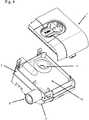
- FIG 1shows a perspective view of a tub module for a humidifier comprising a tub cover or lid 1, a central portion 2 with a humidifier outlet 9 and a humidifier inlet 8, and a tub or tub base 3, which is shown in more detail in the perspective view of Figure 5 .
- the humidifier outlet 9may be, e.g., a conical hose nipple such as a 22 mm standard connector according to ISO 5356-1.
- the humidifier inlet 8preferably comprises an adapter having a sealing lip 10 (see Figure 3 ).
- the central portion 2comprises a spillback protection.
- Spillback protectionmay, e.g., be achieved by an intermediate plate or panel 12 (see Figure 4 ) comprising a through hole 11 which is adapted to let air pass from the device via the humidifier inlet 8 to the water reservoir or container(not shown). The air is humidified within said water reservoir before being forwarded to the patient via humidifier outlet 9. If the entire tub module (or the humidifier comprising said tub module) is being tilted, water within the water reservoir may not flow back into the device because the intermediate plate or panel 12 functions as a barrier.
- the through hole 11is provided at the side opposite the device / device interface in order to improve spillback protection.
- the tubcomprises a container 4 made of a first material, a support or supporting structure 5, a heating element 6, and a lining 7 made of a second, different material.
- the container 4comprises a base 4a and a sidewall 4b defining a reservoir for supply of liquid to be evaporated.
- the heating element 6 of this arrangementis provided on the base 4a of the container with the optional supporting structure 5 being arranged therebetween.
- a heating elementmay be provided on another inner surface of the container, e.g. on one or more surfaces of inner sidewall 4b.
- the lining 7covers the heating element 6 and optionally essentially the entire inner surface of the sidewall 4b of the container as shown in Figure 5 .
- the heating element 6may comprise a tongue with electrical contacts 6a to electrically connect to the heating element 6.
- the supporting structure 5, which is entirely optional,is shown in Figure 6 as a separate layer or element, it is preferred that supporting structure 5 is integral with the heating element 6.
- the supporting structureis advantageous in that it may, e.g., protect the heating element during the molding process.
- the lining 7covers essentially the entire inner surface of the sidewall 4b of the container 4 and forms a sealing lip 7a at the top of the container 4. This sealing lip 7a provides a sealing for the tub cover or lid 1 and the central portion 2, respectively.
- the tub shown in Figures 1 to 4may be removably electrically connected to a base station comprising control electronics via the tongue with electrical contacts 6a of the heating element 6, which protrude from the tub as shown in Figures 2 and 3 .
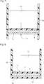
- Figs. 7 and 8show cross sectional views of a humidifier tub according to the present technology.
- the tubincludes a lining 7 provided over the heating element 6.
- the lining 7may be overmolded over the heating element 6 to provide a water and/or vapor sealed protection layer across the heating surface.
- the lining 7is preferably thermally conductive so as to effectively transfer heat from the hot plate or heating element 6 to the water in the tub.
- the lining 7is preferably formed of a bio-compatible material and may be formed of silicone, Teflon®, UV cured polymers or other thermally conductive plastic materials, such as CoolPolyTM products.
- the liningmay also provide an easily cleanable surface.
- the liningmay allow the heating element 6 to be inserted or located directly within the water tub, which may provide enhanced thermal performance.
- Fig. 7shows an example of a humidifier tub with an open base or bottom.
- the tubincludes plastic molded sidewalls 4b and a heating assembly 14 that cooperate to define a water chamber or compartment for water 13.
- the heating assembly 14includes an overmolded lining 7, a thermally conductive support structure 15 (e.g., metal hot plate), and a heating element 6 having heating tracks abutting against the support structure 15.
- the heating assemblyis spaced upwardly from the lower ends of the sidewalls 4b.
- the sidewalls 4bmay be overmolded onto the heating apparatus, without a bottom wall or bottom protective layer. Other materials with high thermal insulation may be used for the overmold.
- an insulator or bottom wallmay be provided to the tub below the heating element 6.
- Fig. 8shows an example of a humidifier tub with a closed base or bottom 4a.
- the tub 4includes plastic molded sidewalls 4b, a plastic molded bottom or base wall 4a, and a heating assembly 14 that cooperate to define a water chamber or compartment for water 13.
- the heating assemblyincludes an overmolded lining 7, a thermally conductive support structure 15 (e.g. metal hot plate), and a heating element 6 providing heating tracks.
- the sidewalls 4b and bottom or base wall 4amay be overmolded onto the heating apparatus.
- Fig. 9shows another example where the lining 7 is overmolded over the inner surface of the side walls 4b and around the heating assembly 14 at the bottom or base 4a of the tub.
Landscapes
- Health & Medical Sciences (AREA)
- Engineering & Computer Science (AREA)
- Life Sciences & Earth Sciences (AREA)
- Veterinary Medicine (AREA)
- Biomedical Technology (AREA)
- Heart & Thoracic Surgery (AREA)
- Hematology (AREA)
- Pulmonology (AREA)
- Animal Behavior & Ethology (AREA)
- General Health & Medical Sciences (AREA)
- Public Health (AREA)
- Emergency Medicine (AREA)
- Anesthesiology (AREA)
- Mechanical Engineering (AREA)
- General Engineering & Computer Science (AREA)
- Sustainable Energy (AREA)
- Thermal Sciences (AREA)
- Physics & Mathematics (AREA)
- Sustainable Development (AREA)
- Chemical & Material Sciences (AREA)
- Combustion & Propulsion (AREA)
- Manufacturing & Machinery (AREA)
- Air Humidification (AREA)
- External Artificial Organs (AREA)
Description
- The present application generally relates to tubs for humidifiers and to methods of manufacturing tubs for humidifiers.
- Humidifiers are generally used for a wide range of applications. An important application for a humidifier is a respiratory apparatus which commonly uses devices to alter the humidity of the breathable gas in order to reduce drying of the patient's airway and consequent patient discomfort and associated complications. Such humidifiers are either integrated with, or configured to be coupled to, the respiratory apparatus.
- Humidifiers typically comprise a water tub having a capacity of several hundred millilitres, a heating element for heating the water in the tub, a control to enable the level of humidification to be varied, a gas inlet to receive gas from the respiratory apparatus, and a gas outlet adapted to be connected to a gas conduit that delivers the humidified, pressurized flow of breathable gas to the patient's mask. The water in the water tub is typically heated via thermal conduction between the heating element and the tub base of the water tub, which is commonly formed of aluminium or stainless steel. On the one hand, good heat flux between the heating element and the water within the water tub is desirable while on the other the electronics of the heating element and the control should be properly insulated from the water within the water tub.
WO 2008/148154 A1 , the content of which is incorporated herein in its entirety, describes inmolded heaters for heating fluids within containers which may be used in a respiratory humidification device.WO 2008/148154 A1 in particular discloses a humidifier comprising a tub configured to contain a supply of water and a heater comprising a first polymer foam having an electrically conductive circuit provided upon a surface, wherein the first polymer foam is electrically insulating and the tub is formed of molded resin and the heater is molded at least partially within the resin. The heater is relatively rigidly secured and molded within the humidifier tub.- Documents
US 2010/0147299 andEP 2 720 746 - The invention is defined in the appended claims.
- The present technology provides a tub for a humidifier. The tub comprises a container made of a first material, a heating element, and a lining including a second, preferably biocompatible, material different from the first material. The container comprises a base and a sidewall defining a reservoir for a supply of liquid to be evaporated. The heating element may be provided on the base of the container and the lining covers at least the heating element. The heating element may be provided additionally or alternatively in other parts of the container, such as on or in one or more side walls. The lining may also cover a substantial portion of the inner surface of the sidewall of the container. Thus, the first material may be chosen to be, e.g., sufficiently stable and/or scratch resistant to provide a stable container. The second material, on the other hand, may be chosen such as to provide a preferably elastic lining which is adapted to electrically insulate the supply of water from the heating element and at the same time accommodate any stress caused by thermal expansion of, e.g., the heating element. In this context, the term "elastic" refers to being adaptable in allowing some expansion and contraction of the material to compensate for expansion and contraction of the heating element in response to changes in temperature. Furthermore, the first material may be chosen to be substantially insulating to heat transport in order to reduce the energy used for keeping the supply of liquid at a predetermined temperature, while the second material may be chosen to be a particularly good heat conductor in order to provide for effective heat transport from the heating element to the supply of liquid.
- Accordingly, the tub according to the present technology is advantageous over known tubs for humidifiers in that the use of two different materials allows for a tub design which preferably suits various demands. Furthermore, the tub according to the present technology may be easily manufactured which allows for a cost efficient production process.
- The lining may be molded, preferably injection-molded, over the heating element and optionally also over a substantial portion of the inner surface of the sidewall of the container. This further eases the manufacturing and allows for perfect sealing avoiding any creep flow of liquid between the first and second materials towards the heating element. However, other ways to provide for a lining are also envisaged. For example, a pre-manufactured lining may be clamped into the inside of the container or may be attached to the heating element and the inner surface of the sidewall of the container by means of adhesive or any other fastening systems.
- In certain aspects the lining may be formed of a plurality of materials wherein at least a portion of the lining is formed of the second material to cover the heater element. For example the lining includes a portion of the elastic or flexible second material covering the heater element coupled with a different material, optionally the same as the first material, that covers the remainder of the internal surface of the humidifier tub. Furthermore, the lining may cover the heater element or the heater element and a substantial portion of the inner surface of the container or humidifier tub. For example, the heating element may be covered with a lining made of silicone, preferably biocompatible silicone, whereas a portion of or essentially the entire internal surface of the container may be molded over with another, preferably harder material.
- According to another aspect, the lining is formed entirely of the second material and according to the invention, covers the entire inner surface of the sidewall of the container. This further improves the sealing since the transition region between the first and second materials is most prone to leakage.
- The second material may comprise silicone, a thermoplastic elastomer (TPE), or other thermally conductive flexible polymers. Even though the thermal conductivity of silicone is rather low, it may be easily injection-molded in a thin layer over the heating element and the inner surface of the sidewall of the container, thus providing excellent electrical insulation between the liquid within the reservoir and the heating element while still allowing for sufficient heat transport from the heating element to the liquid. Furthermore, silicone is biocompatible and sufficiently flexible to accommodate any stress caused by thermal expansion.
- According to the invention the second material is biocompatible, such as biocompatible silicone, it may also serve as a barrier against any substances in the first material that are not biocompatible such as Bisphenol A. Thus, the use of a biocompatible second material for the lining allows for the use of various materials for the container which, without such lining, could not be used.
- It is further preferred that the first material comprises, preferably consists of, one or a combination of polycarbonate, polysulfone, polymethylmethacrylate, and polybutylene terephthalate. While these materials are known to be easily formable and suitable to provide for a stable container, other materials having similar properties may be used as well.
- The lining preferably has a thickness between 0.5 mm and 5 mm, more preferred between 1 mm and 3 mm. A thin lining improves the heat transport while a thicker lining is more durable.
- Since the heating element is essentially surrounded by or sealed between the first and second materials, basically any known heating element may be used in the context of the present technology. Suitable heating elements are, inter alia, printed foil heaters, silicone heaters, carbon fiber heaters, etched metal heaters, Kapton heating elements and silicone heating panels. Yet, basically any other known heating element may be used as long as it is sufficiently small and provides sufficient energy to heat the supply of liquid to the required temperature. In certain aspects, the heating element may include the heating element described in pending
U.S. provisional application 61/6,286,622 . - According to the invention, the heating element is coated with an insulating material on at least one side, preferably the bottom side, in order to avoid excessive heat transport from the heating element towards the surrounding of the tub, i.e, to reduce energy waste. Suitable materials are, e.g., silicone and/or silicone foam. However, other materials, in particular, other foams, may be used. The heat insulating material may be complemented with or replaced with a material which reflects thermal radiation, in particular infrared radiation. Thus, heat loss towards the surrounding atmosphere is reduced. Alternatively, or in addition, heat loss may be further decreased by providing a hollow space on one side of, preferably below, the heating element. A particularly preferred aspect combines a hollow, preferably vacuum, space below the heating element with a reflector for infrared radiation.
- Preferably, the heating element comprises a plug or connector to electrically connect to the heating element. In one aspect a plug or connector may comprise a tongue with electrical contacts. Furthermore, the tub may comprise one of or different combinations of a temperature sensor, a pressure sensor, a humidity sensor, one or more LEDs, a thermal overload protection and/or means for sensing the level of the supply of liquid such as a capacitive sensor for measuring the water level within the container or reservoir.
- The container of the tub may be manufactured by any known means. However, it is preferred to mold, preferably, injection-mold, the container. It is preferred that the tub further comprises a support or supporting structure. The supporting structure preferably comprises one or more of a metal sheet or plate, an aluminium sheet or plate, a (high grade) steel sheet or plate, a fibreglass sheet or plate, and/or a printed circuit board. The supporting structure may increase the stability of the tub and may in particular support and/or protect the heating element from any impacts and/or from stress or strain occurring during the molding process. Preferably, the supporting structure is integral with the heating element. For example, the heating element may be laminated to the supporting structure or the printed circuit board, which provides the support structure, and also comprises the heating element.
- According to the invention, the tub further comprises a lid, wherein the lining provides a sealing for the lid. For example, if the lining covers substantially the entire inner surface of the sidewall of the container, the lid may have a protrusion which fits within the sidewall of the container and engages the lining on the inner surface of the sidewall of the container.
- According to the invention, the lining forms a sealing lip at the top of the container in order to provide a sealing for the lid.
- The tub may further comprise a flow plate, wherein the lining provides a sealing for the flow plate.
- Further aspects may be directed at a humidifier comprising a base station and a tub as described above. The tub preferably can be removably attached to the base station. It is further preferred that the base station comprises control electronics which can be removably electrically connected to the heating element of the tub.
- Further aspects relate to a method of manufacturing a tub for a humidifier, preferably a tub as described above. According to the inventive method, a tool for molding, preferably injection-molding, a container is provided. A heating element is then positioned inside or within said tool and a container is molded, preferably injection-molded, around said heating element. The container is made of a first material and comprises a base and a sidewall defining a reservoir for a supply of liquid to be evaporated, wherein the heating element is arranged on the base and/or sidewalls of the container. Optionally, a supporting structure and/or a plug or connector is provided. Finally, a second, preferably biocompatible, material different from the first material is molded, preferably injection-molded, over at least the heating element and optionally a substantial portion of the inner surface of the sidewall of the container to provide a lining. In case a supporting structure and/or a plug or connector is provided, the second material is also molded over the supporting structure and/or the plug or connector, preferably in such a way as to protect the plug and/or connector from water without affecting or blocking the electrical connections to the base station.
- All advantageous and/or preferred features described above with respect to the tub may also be employed for the inventive method. In particular, the materials and dimensions mentioned above with respect to the tub are also preferred for the inventive method.
- Preferably, the heating element is preheated to a predetermined temperature before the step of molding the first material. Preferably, the predetermined temperature is between 50° Celsius and 200° Celsius, more preferred between 100° Celsius and 150° Celsius. Preferably, the predetermined temperature is similar or even approximately equal to the molding tool. Thus, the manufacturing process can be more precisely controlled and repeatability can be improved. For example, if the heating element is much colder than the molding tool (e.g. due to its storage) molding may be negatively affected. All the more so if the temperature of the heating element varies from time to time. Keeping the heating element always at the same controlled and predetermined temperature by preheating prevents such variations and possible detrimental effects.
- Further details of the tub are described in Australian Provisional Application No.
2011902350, filed June 16, 2011 U.S. Provisional Application No. 61/628,622, filed November 3, 2011 PCT/AU2012/000693 file 15 June 2012 - In particular,
PCT/AU2012/000693 - Further details regarding the thermally conductive laminate layer are described in paragraphs [0059] to [0062], the heating element in paragraphs [0063] to [0065], the protective layer in paragraphs [0066] to [0069], the electrical leads in paragraph [0070] and the contact pads in paragraphs [0071] and [0072], all of which are incorporated by reference.
- Preferred arrangements of a tub according to the present technology are further elucidated with reference to the following Figures:
Figures 1 to 3 show perspective views of a tub according to an example of the present technology comprising a tub base, a tub center and a tub cover.Figure 4 shows a partially exploded view of the tub ofFigure 1 .Figure 5 shows a perspective view of the tub base shown inFigures 1 to 4 .Figure 6 shows an exploded view of the tub base ofFigure 5 .Figure 7 shows a schematic cross sectional view of a humidifier tub according to an example of the present technology;Figure 8 shows a schematic cross sectional view of a humidifier tub according to an example of the present technology;Figure 9 shows another schematic cross sectional view of a humidifier tub according to an example of the present technology.Figure 1 shows a perspective view of a tub module for a humidifier comprising a tub cover orlid 1, acentral portion 2 with ahumidifier outlet 9 and ahumidifier inlet 8, and a tub ortub base 3, which is shown in more detail in the perspective view ofFigure 5 . Thehumidifier outlet 9 may be, e.g., a conical hose nipple such as a 22 mm standard connector according to ISO 5356-1. Thehumidifier inlet 8 preferably comprises an adapter having a sealing lip 10 (seeFigure 3 ).- Preferably, the
central portion 2 comprises a spillback protection. Spillback protection may, e.g., be achieved by an intermediate plate or panel 12 (seeFigure 4 ) comprising a throughhole 11 which is adapted to let air pass from the device via thehumidifier inlet 8 to the water reservoir or container(not shown). The air is humidified within said water reservoir before being forwarded to the patient viahumidifier outlet 9. If the entire tub module (or the humidifier comprising said tub module) is being tilted, water within the water reservoir may not flow back into the device because the intermediate plate orpanel 12 functions as a barrier. Preferably, the throughhole 11 is provided at the side opposite the device / device interface in order to improve spillback protection. - As may be taken from the exploded view of the tub or
tub base 3 shown inFigure 6 , the tub comprises acontainer 4 made of a first material, a support or supportingstructure 5, aheating element 6, and alining 7 made of a second, different material. Thecontainer 4 comprises abase 4a and asidewall 4b defining a reservoir for supply of liquid to be evaporated. Theheating element 6 of this arrangement is provided on thebase 4a of the container with the optional supportingstructure 5 being arranged therebetween. Alternatively or in addition, a heating element may be provided on another inner surface of the container, e.g. on one or more surfaces ofinner sidewall 4b. Thelining 7 covers theheating element 6 and optionally essentially the entire inner surface of thesidewall 4b of the container as shown inFigure 5 . - As shown the
heating element 6 may comprise a tongue withelectrical contacts 6a to electrically connect to theheating element 6. While the supportingstructure 5, which is entirely optional, is shown inFigure 6 as a separate layer or element, it is preferred that supportingstructure 5 is integral with theheating element 6. The supporting structure is advantageous in that it may, e.g., protect the heating element during the molding process. In the arrangement shown inFigure 5 , thelining 7 covers essentially the entire inner surface of thesidewall 4b of thecontainer 4 and forms a sealinglip 7a at the top of thecontainer 4. This sealinglip 7a provides a sealing for the tub cover orlid 1 and thecentral portion 2, respectively. - The tub shown in
Figures 1 to 4 may be removably electrically connected to a base station comprising control electronics via the tongue withelectrical contacts 6a of theheating element 6, which protrude from the tub as shown inFigures 2 and3 . - While the arrangement shown in
Figures 1 to 4 comprises rather specific features such as the snap hook interface at thetop cover 1 and the device interface and spill back protection at thecentral portion 2, it is evident that these features are not essential to the present technology and that the claims are not to be construed to be limited to such features. In particular, the entire tub as well as all of its components may have an entirely different geometric shape, e.g., round rather than rectangular or the like. Furthermore, other heating elements than theheating element 6 shown inFigure 6 may be employed and thelining 7 may not cover the entire inner surface of thesidewall 4b of thecontainer 4, but rather a substantial portion thereof. Moreover, the shape and type of the electrical connections may vary. Figs. 7 and 8 show cross sectional views of a humidifier tub according to the present technology. The tub includes alining 7 provided over theheating element 6. Thelining 7 may be overmolded over theheating element 6 to provide a water and/or vapor sealed protection layer across the heating surface. Thelining 7 is preferably thermally conductive so as to effectively transfer heat from the hot plate orheating element 6 to the water in the tub. Furthermore thelining 7 is preferably formed of a bio-compatible material and may be formed of silicone, Teflon®, UV cured polymers or other thermally conductive plastic materials, such as CoolPoly™ products. The lining may also provide an easily cleanable surface.- Furthermore, the lining may allow the
heating element 6 to be inserted or located directly within the water tub, which may provide enhanced thermal performance. Fig. 7 shows an example of a humidifier tub with an open base or bottom. As illustrated, the tub includes plastic moldedsidewalls 4b and aheating assembly 14 that cooperate to define a water chamber or compartment forwater 13. Theheating assembly 14 includes anovermolded lining 7, a thermally conductive support structure 15 (e.g., metal hot plate), and aheating element 6 having heating tracks abutting against thesupport structure 15. As illustrated, the heating assembly is spaced upwardly from the lower ends of thesidewalls 4b. Thesidewalls 4b may be overmolded onto the heating apparatus, without a bottom wall or bottom protective layer. Other materials with high thermal insulation may be used for the overmold. Also, an insulator or bottom wall (not shown) may be provided to the tub below theheating element 6.Fig. 8 shows an example of a humidifier tub with a closed base or bottom 4a. As illustrated, thetub 4 includes plastic moldedsidewalls 4b, a plastic molded bottom orbase wall 4a, and aheating assembly 14 that cooperate to define a water chamber or compartment forwater 13. The heating assembly includes anovermolded lining 7, a thermally conductive support structure 15 (e.g. metal hot plate), and aheating element 6 providing heating tracks. Thesidewalls 4b and bottom orbase wall 4a may be overmolded onto the heating apparatus.Fig. 9 shows another example where thelining 7 is overmolded over the inner surface of theside walls 4b and around theheating assembly 14 at the bottom orbase 4a of the tub.- While the technology has been described in connection with several examples, it is to be understood that the technology is not to be limited to the disclosed examples, but on the contrary, is intended to cover various modifications and equivalent arrangements included within the spirit and scope of the technology. Also, the various examples described above may be implemented in conjunction with other examples, e.g., one or more aspects of one example may be combined with one or more aspects of another example to realize yet other examples. Further, each independent feature or component of any given assembly may constitute an additional example. In addition, while the technology has particular application to patients who suffer from OSA, it is to be appreciated that patients who suffer from other illnesses (e.g., congestive heart failure, diabetes, morbid obesity, stroke, bariatric surgery, etc.) can derive benefit from the above teachings. Moreover, the above teachings have applicability with patients and non-patients alike in non-medical applications.
Claims (17)
- A tub for a humidifier comprising:a container (4) made of a first material,a heating element (6), anda lining (7) comprising a second material different from the first material, wherein the second material is biocompatible and elastic;wherein the container comprises a base (4a) and a side wall (4b) defining a reservoir for a supply of liquid to be evaporated, the heating element is provided on an inner surface of the container, and the lining covers at least the heating element and the entire inner surface of the side wall of the container;wherein the tub further comprises a lid (1), wherein the lining provides a sealing for the lid.
- The tub of claim 1, wherein the heating element is provided on at least the base of the container.
- The tub of any one of claims 1-2, wherein the lining is molded over at least the heating element, more preferably, the lining is injection-molded over at least the heating element.
- The tub of any of one of claims 1-3, wherein the second material comprises silicone, preferably biocompatible silicone.
- The tub of any one of claims 1-4, wherein the heating element is coated with an insulating material, preferably, the insulating material comprises silicone and/or silicone foam.
- The tub of claim 5, wherein the heating element is coated with the insulating material on a bottom side.
- The tub of any one of claims 1-6, wherein a hollow space is provided on one side of the heating element, more preferably, below the heating element.
- The tub of any one of claims 1-7, wherein the heating element comprises a plug or connector to electrically connect to the heating element.
- The tub of any one of claims 1-8, wherein the heating element comprises a tongue with electrical contacts.
- The tub of any one of claims 1-9, further comprising one or a combination of the following: temperature sensor, pressure sensor, humidity sensor, one or more LEDs, thermal overload protection, means for sensing the level of the supply of liquid.
- The tub of claim 1, wherein the lining forms a sealing lip at a top of the container.
- The tub of any one of claims 1-11, further comprising a flow plate, wherein the lining provides a sealing for the flow plate.
- A humidifier comprising a base station and a tub according to any of claims 1 to 12, wherein the tub can be removably attached to the base station.
- The humidifier of claim 13, wherein the base station comprises control electronics which can be removably electrically connected to the heating element of the tub.
- Method of manufacturing a tub for a humidifier according to any of claims 1 to 14, comprising the steps of:a) providing a tool for molding a container;b) positioning a heating element inside said tool;c) molding, preferably injection-molding, a container made of a first material around said heating element, wherein the container comprises a base and a side wall defining a reservoir for a supply of liquid to be evaporated, wherein the heating element is arranged on an inner surface of the container; andd) molding a second material different from the first material over at least the heating element on an inner surface of the container in order to provide a lining.
- The method of claim 15, wherein the heating element is arranged on at least the base of the container.
- The method of any one of claims 15 and 16, wherein the heating element is preheated to a predetermined temperature before the step of molding the first material, preferably the predetermined temperature is between 50 °C and 200 °C, more preferably between 100 °C and 150 °C.
Priority Applications (2)
| Application Number | Priority Date | Filing Date | Title |
|---|---|---|---|
| EP22204438.0AEP4197582B1 (en) | 2012-03-15 | 2012-11-02 | Tub for humidifier |
| EP19218469.5AEP3708213B1 (en) | 2012-03-15 | 2012-11-02 | Heating apparatus |
Applications Claiming Priority (2)
| Application Number | Priority Date | Filing Date | Title |
|---|---|---|---|
| US201261611137P | 2012-03-15 | 2012-03-15 | |
| PCT/EP2012/071739WO2013135318A1 (en) | 2012-03-15 | 2012-11-02 | Heating apparatus |
Related Child Applications (2)
| Application Number | Title | Priority Date | Filing Date |
|---|---|---|---|
| EP19218469.5ADivisionEP3708213B1 (en) | 2012-03-15 | 2012-11-02 | Heating apparatus |
| EP22204438.0ADivisionEP4197582B1 (en) | 2012-03-15 | 2012-11-02 | Tub for humidifier |
Publications (2)
| Publication Number | Publication Date |
|---|---|
| EP2825236A1 EP2825236A1 (en) | 2015-01-21 |
| EP2825236B1true EP2825236B1 (en) | 2019-12-25 |
Family
ID=47257754
Family Applications (3)
| Application Number | Title | Priority Date | Filing Date |
|---|---|---|---|
| EP12791708.6AActiveEP2825236B1 (en) | 2012-03-15 | 2012-11-02 | Heating apparatus |
| EP19218469.5AActiveEP3708213B1 (en) | 2012-03-15 | 2012-11-02 | Heating apparatus |
| EP22204438.0AActiveEP4197582B1 (en) | 2012-03-15 | 2012-11-02 | Tub for humidifier |
Family Applications After (2)
| Application Number | Title | Priority Date | Filing Date |
|---|---|---|---|
| EP19218469.5AActiveEP3708213B1 (en) | 2012-03-15 | 2012-11-02 | Heating apparatus |
| EP22204438.0AActiveEP4197582B1 (en) | 2012-03-15 | 2012-11-02 | Tub for humidifier |
Country Status (3)
| Country | Link |
|---|---|
| US (2) | US10317098B2 (en) |
| EP (3) | EP2825236B1 (en) |
| WO (1) | WO2013135318A1 (en) |
Families Citing this family (26)
| Publication number | Priority date | Publication date | Assignee | Title |
|---|---|---|---|---|
| CN101690385B (en)* | 2007-06-05 | 2015-05-27 | 瑞思迈有限公司 | Electric heater, in particular for humidification and liquid heating |
| AT509046B1 (en) | 2010-03-10 | 2011-06-15 | Helmut Dr Buchberger | FLAT EVAPORATOR |
| EP4169560B1 (en) | 2011-07-13 | 2025-09-17 | Fisher & Paykel Healthcare Limited | Bearing mount for a compressor or blower for providing respiratory assistance |
| EP2825236B1 (en)* | 2012-03-15 | 2019-12-25 | ResMed Pty Ltd | Heating apparatus |
| CN205515844U (en) | 2012-12-18 | 2016-08-31 | 费雪派克医疗保健有限公司 | Breathe auxiliary device and be used for assembly of motor |
| US9726390B2 (en) | 2013-10-30 | 2017-08-08 | Fisher & Paykel Healthcare Limited | Humidifier arrangements and control systems |
| EP4166176B1 (en) | 2013-12-17 | 2025-08-06 | ResMed Pty Ltd | Apparatus for use in treating a respiratory disorder |
| CA2936923C (en)* | 2014-01-30 | 2022-07-26 | Fisher & Paykel Healthcare Limited | Breathing assistance apparatus with liquid containment |
| US10052449B2 (en) | 2014-03-21 | 2018-08-21 | Fisher & Paykel Healthcare Limited | Heating arrangements for humidification systems |
| GB201411483D0 (en) | 2014-06-27 | 2014-08-13 | Batmark Ltd | Vaporizer Assembly |
| NZ737589A (en) | 2015-06-24 | 2023-03-31 | Fisher & Paykel Healthcare Ltd | Breathing assistance apparatus |
| SG11201805302UA (en)* | 2015-12-23 | 2018-07-30 | Fisher & Paykel Healthcare Ltd | Heating arrangements for humidification systems |
| EP4218879A1 (en)* | 2016-11-22 | 2023-08-02 | ResMed Pty Ltd | Humidifier reservoir |
| CN114288512B (en) | 2017-04-23 | 2024-12-13 | 费雪派克医疗保健有限公司 | Respiratory assistance equipment |
| USD873283S1 (en) | 2017-08-01 | 2020-01-21 | D-M-S Holdings, Inc. | Computerized display device with graphical user interface for target humidity |
| US10830469B2 (en) | 2017-08-01 | 2020-11-10 | D-M-S Holdings, Inc. | Humidifier measurement and control |
| USD865930S1 (en) | 2017-08-01 | 2019-11-05 | D-M-S Holdings, Inc. | Humidifier |
| US11376392B2 (en)* | 2018-04-24 | 2022-07-05 | ResMed Pty Ltd | Tub for use in a humidifier |
| CN112512615A (en)* | 2018-05-09 | 2021-03-16 | 斐雪派克医疗保健有限公司 | Medical component having thermoplastic molded article bonded to substrate |
| IT201800005586A1 (en)* | 2018-05-22 | 2019-11-22 | ACTIVE HUMIDIFIER AND THERMOREGULATED CIRCUIT INTEGRATING THIS ACTIVE HUMIDIFIER. | |
| GB201817860D0 (en) | 2018-11-01 | 2018-12-19 | Nicoventures Trading Ltd | Aerosolised formulation |
| WO2020128829A1 (en) | 2018-12-18 | 2020-06-25 | ResMed Pty Ltd | Humidifier reservoir |
| USD921900S1 (en) | 2018-12-19 | 2021-06-08 | ResMed Pty Ltd | Humidification tub |
| CN116637264A (en) | 2019-04-17 | 2023-08-25 | 瑞思迈私人有限公司 | CPAP system |
| WO2021127732A1 (en)* | 2019-12-24 | 2021-07-01 | ResMed Pty Ltd | Apparatus for humidifying a respiratory gas |
| US20230075277A1 (en)* | 2021-08-26 | 2023-03-09 | ResMed Pty Ltd | Air preheater for humidification tub |
Citations (1)
| Publication number | Priority date | Publication date | Assignee | Title |
|---|---|---|---|---|
| EP2720746A1 (en)* | 2011-06-16 | 2014-04-23 | ResMed Limited | Humifier and layered heating element |
Family Cites Families (27)
| Publication number | Priority date | Publication date | Assignee | Title |
|---|---|---|---|---|
| US3809374A (en)* | 1969-06-11 | 1974-05-07 | G Schossow | Vaporizer-humidifier |
| US3672568A (en)* | 1970-08-12 | 1972-06-27 | Foote Allen | Humidifier |
| US3694622A (en) | 1971-01-07 | 1972-09-26 | Ralph L Bentley | Heater |
| US4222971A (en)* | 1978-11-14 | 1980-09-16 | Eilert Richard L | Humidifier liner |
| US5522523A (en)* | 1994-02-14 | 1996-06-04 | Southcorp Water Heaters Usa, Inc. | Water heater having flexible liner and method for making the same |
| US5546926A (en)* | 1994-10-07 | 1996-08-20 | Lake; Jared L. | Whole house humidifier for use with hot air heating systems |
| US5752498A (en)* | 1994-10-07 | 1998-05-19 | Lake; Jared L. | Elliptical beam load cell |
| WO1999036016A1 (en) | 1998-01-19 | 1999-07-22 | Simply Silence Simsin B.V. | Hearing protector |
| AUPQ339099A0 (en)* | 1999-10-13 | 1999-11-04 | Resmed Limited | A humidifier |
| US6706594B2 (en) | 2001-07-13 | 2004-03-16 | Micron Technology, Inc. | Optimized flash memory cell |
| US7049558B2 (en) | 2003-01-27 | 2006-05-23 | Arcturas Bioscience, Inc. | Apparatus and method for heating microfluidic volumes and moving fluids |
| KR100526206B1 (en) | 2003-03-21 | 2005-11-08 | 삼성전자주식회사 | Cooking Apparatus |
| JP4865545B2 (en)* | 2003-06-20 | 2012-02-01 | レスメド・リミテッド | Breathable gas supply device with humidifier |
| AU2003903139A0 (en)* | 2003-06-20 | 2003-07-03 | Resmed Limited | Breathable gas apparatus with humidifier |
| DE102004037698A1 (en)* | 2004-08-02 | 2006-03-16 | Seleon Gmbh | Evaporator as well as evaporation process |
| DE102004037823A1 (en)* | 2004-08-04 | 2006-03-16 | Viasys Healthcare Gmbh | Evaporator, ventilator and evaporation process |
| CN101541367B (en)* | 2006-11-08 | 2014-02-26 | 雷斯梅德有限公司 | Catheters used in breathing apparatus |
| US7789194B2 (en)* | 2007-04-20 | 2010-09-07 | Cardinal Health 212, Inc. | Acoustic attenuation chamber |
| CN101690385B (en)* | 2007-06-05 | 2015-05-27 | 瑞思迈有限公司 | Electric heater, in particular for humidification and liquid heating |
| US8550075B2 (en)* | 2007-06-28 | 2013-10-08 | Resmed Limited | Removable and/or replaceable humidifier |
| EP2337604B1 (en)* | 2008-09-17 | 2018-01-24 | ResMed Limited | Humidification of respiratory gases |
| US8453640B2 (en)* | 2008-11-12 | 2013-06-04 | Resmed Limited | Positive airway pressure device |
| AU2010206053B2 (en)* | 2009-07-31 | 2014-08-07 | ResMed Pty Ltd | Wire Heated Tube with Temperature Control System, Tube Type Detection, and Active Over Temperature Protection for Humidifier for Respiratory Apparatus |
| US9737682B2 (en)* | 2009-09-17 | 2017-08-22 | Resmed Limited | Humidification of respiratory gases |
| EP2825236B1 (en) | 2012-03-15 | 2019-12-25 | ResMed Pty Ltd | Heating apparatus |
| SG10201701548TA (en)* | 2012-09-07 | 2017-03-30 | Fisher & Paykel Healthcare Ltd | Humidification chamber for a respiratory assistance apparatus |
| US9726390B2 (en)* | 2013-10-30 | 2017-08-08 | Fisher & Paykel Healthcare Limited | Humidifier arrangements and control systems |
- 2012
- 2012-11-02EPEP12791708.6Apatent/EP2825236B1/enactiveActive
- 2012-11-02WOPCT/EP2012/071739patent/WO2013135318A1/enactiveApplication Filing
- 2012-11-02EPEP19218469.5Apatent/EP3708213B1/enactiveActive
- 2012-11-02USUS14/384,639patent/US10317098B2/enactiveActive
- 2012-11-02EPEP22204438.0Apatent/EP4197582B1/enactiveActive
- 2019
- 2019-06-05USUS16/432,513patent/US11852356B2/enactiveActive
Patent Citations (1)
| Publication number | Priority date | Publication date | Assignee | Title |
|---|---|---|---|---|
| EP2720746A1 (en)* | 2011-06-16 | 2014-04-23 | ResMed Limited | Humifier and layered heating element |
Also Published As
| Publication number | Publication date |
|---|---|
| EP3708213B1 (en) | 2022-11-02 |
| EP4197582A1 (en) | 2023-06-21 |
| EP4197582B1 (en) | 2025-06-11 |
| WO2013135318A1 (en) | 2013-09-19 |
| US11852356B2 (en) | 2023-12-26 |
| EP3708213A1 (en) | 2020-09-16 |
| NZ629805A (en) | 2016-04-29 |
| US20190390863A1 (en) | 2019-12-26 |
| EP2825236A1 (en) | 2015-01-21 |
| US10317098B2 (en) | 2019-06-11 |
| US20150030317A1 (en) | 2015-01-29 |
Similar Documents
| Publication | Publication Date | Title |
|---|---|---|
| US11852356B2 (en) | Heating apparatus | |
| CN101690385B (en) | Electric heater, in particular for humidification and liquid heating | |
| JP7667334B2 (en) | Humidifier | |
| NZ734898B2 (en) | Heating Apparatus | |
| NZ629805B2 (en) | Heating apparatus | |
| AU2014200883B2 (en) | Heater | |
| AU2015201748A1 (en) | Heater | |
| NZ723636B2 (en) | Humidifier and layered heating element |
Legal Events
| Date | Code | Title | Description |
|---|---|---|---|
| PUAI | Public reference made under article 153(3) epc to a published international application that has entered the european phase | Free format text:ORIGINAL CODE: 0009012 | |
| 17P | Request for examination filed | Effective date:20140915 | |
| AK | Designated contracting states | Kind code of ref document:A1 Designated state(s):AL AT BE BG CH CY CZ DE DK EE ES FI FR GB GR HR HU IE IS IT LI LT LU LV MC MK MT NL NO PL PT RO RS SE SI SK SM TR | |
| AX | Request for extension of the european patent | Extension state:BA ME | |
| RIN1 | Information on inventor provided before grant (corrected) | Inventor name:KIRCHBERGER, ANDREAS Inventor name:ROTHFUSS, JENS Inventor name:BACKHAUS, CHRISTIAN Inventor name:LANG, BERND Inventor name:BIENER, ACHIM Inventor name:NICKOL, JOHANNES Inventor name:BURZ, JOHANN, SEBASTIAN Inventor name:EIBL, ROBERT | |
| DAX | Request for extension of the european patent (deleted) | ||
| STAA | Information on the status of an ep patent application or granted ep patent | Free format text:STATUS: EXAMINATION IS IN PROGRESS | |
| 17Q | First examination report despatched | Effective date:20170117 | |
| REG | Reference to a national code | Ref country code:DE Ref legal event code:R079 Ref document number:602012066739 Country of ref document:DE Free format text:PREVIOUS MAIN CLASS: A61M0016160000 Ipc:B29L0031340000 | |
| RIC1 | Information provided on ipc code assigned before grant | Ipc:B29L 31/34 20060101AFI20190412BHEP Ipc:F22B 1/28 20060101ALI20190412BHEP Ipc:A61M 16/10 20060101ALI20190412BHEP Ipc:B29K 101/12 20060101ALI20190412BHEP Ipc:B29K 21/00 20060101ALI20190412BHEP Ipc:F24F 6/10 20060101ALI20190412BHEP Ipc:A61M 16/16 20060101ALI20190412BHEP Ipc:B29C 45/14 20060101ALI20190412BHEP | |
| GRAP | Despatch of communication of intention to grant a patent | Free format text:ORIGINAL CODE: EPIDOSNIGR1 | |
| STAA | Information on the status of an ep patent application or granted ep patent | Free format text:STATUS: GRANT OF PATENT IS INTENDED | |
| INTG | Intention to grant announced | Effective date:20190524 | |
| RAP1 | Party data changed (applicant data changed or rights of an application transferred) | Owner name:RESMED PTY LTD | |
| GRAS | Grant fee paid | Free format text:ORIGINAL CODE: EPIDOSNIGR3 | |
| GRAA | (expected) grant | Free format text:ORIGINAL CODE: 0009210 | |
| STAA | Information on the status of an ep patent application or granted ep patent | Free format text:STATUS: THE PATENT HAS BEEN GRANTED | |
| AK | Designated contracting states | Kind code of ref document:B1 Designated state(s):AL AT BE BG CH CY CZ DE DK EE ES FI FR GB GR HR HU IE IS IT LI LT LU LV MC MK MT NL NO PL PT RO RS SE SI SK SM TR | |
| REG | Reference to a national code | Ref country code:GB Ref legal event code:FG4D | |
| REG | Reference to a national code | Ref country code:CH Ref legal event code:EP | |
| REG | Reference to a national code | Ref country code:AT Ref legal event code:REF Ref document number:1216705 Country of ref document:AT Kind code of ref document:T Effective date:20200115 | |
| REG | Reference to a national code | Ref country code:DE Ref legal event code:R096 Ref document number:602012066739 Country of ref document:DE | |
| REG | Reference to a national code | Ref country code:IE Ref legal event code:FG4D | |
| REG | Reference to a national code | Ref country code:NL Ref legal event code:MP Effective date:20191225 | |
| PG25 | Lapsed in a contracting state [announced via postgrant information from national office to epo] | Ref country code:FI Free format text:LAPSE BECAUSE OF FAILURE TO SUBMIT A TRANSLATION OF THE DESCRIPTION OR TO PAY THE FEE WITHIN THE PRESCRIBED TIME-LIMIT Effective date:20191225 Ref country code:BG Free format text:LAPSE BECAUSE OF FAILURE TO SUBMIT A TRANSLATION OF THE DESCRIPTION OR TO PAY THE FEE WITHIN THE PRESCRIBED TIME-LIMIT Effective date:20200325 Ref country code:LV Free format text:LAPSE BECAUSE OF FAILURE TO SUBMIT A TRANSLATION OF THE DESCRIPTION OR TO PAY THE FEE WITHIN THE PRESCRIBED TIME-LIMIT Effective date:20191225 Ref country code:SE Free format text:LAPSE BECAUSE OF FAILURE TO SUBMIT A TRANSLATION OF THE DESCRIPTION OR TO PAY THE FEE WITHIN THE PRESCRIBED TIME-LIMIT Effective date:20191225 Ref country code:LT Free format text:LAPSE BECAUSE OF FAILURE TO SUBMIT A TRANSLATION OF THE DESCRIPTION OR TO PAY THE FEE WITHIN THE PRESCRIBED TIME-LIMIT Effective date:20191225 Ref country code:NO Free format text:LAPSE BECAUSE OF FAILURE TO SUBMIT A TRANSLATION OF THE DESCRIPTION OR TO PAY THE FEE WITHIN THE PRESCRIBED TIME-LIMIT Effective date:20200325 | |
| REG | Reference to a national code | Ref country code:LT Ref legal event code:MG4D | |
| PG25 | Lapsed in a contracting state [announced via postgrant information from national office to epo] | Ref country code:HR Free format text:LAPSE BECAUSE OF FAILURE TO SUBMIT A TRANSLATION OF THE DESCRIPTION OR TO PAY THE FEE WITHIN THE PRESCRIBED TIME-LIMIT Effective date:20191225 Ref country code:RS Free format text:LAPSE BECAUSE OF FAILURE TO SUBMIT A TRANSLATION OF THE DESCRIPTION OR TO PAY THE FEE WITHIN THE PRESCRIBED TIME-LIMIT Effective date:20191225 | |
| PG25 | Lapsed in a contracting state [announced via postgrant information from national office to epo] | Ref country code:AL Free format text:LAPSE BECAUSE OF FAILURE TO SUBMIT A TRANSLATION OF THE DESCRIPTION OR TO PAY THE FEE WITHIN THE PRESCRIBED TIME-LIMIT Effective date:20191225 | |
| PG25 | Lapsed in a contracting state [announced via postgrant information from national office to epo] | Ref country code:EE Free format text:LAPSE BECAUSE OF FAILURE TO SUBMIT A TRANSLATION OF THE DESCRIPTION OR TO PAY THE FEE WITHIN THE PRESCRIBED TIME-LIMIT Effective date:20191225 Ref country code:NL Free format text:LAPSE BECAUSE OF FAILURE TO SUBMIT A TRANSLATION OF THE DESCRIPTION OR TO PAY THE FEE WITHIN THE PRESCRIBED TIME-LIMIT Effective date:20191225 Ref country code:RO Free format text:LAPSE BECAUSE OF FAILURE TO SUBMIT A TRANSLATION OF THE DESCRIPTION OR TO PAY THE FEE WITHIN THE PRESCRIBED TIME-LIMIT Effective date:20191225 Ref country code:PT Free format text:LAPSE BECAUSE OF FAILURE TO SUBMIT A TRANSLATION OF THE DESCRIPTION OR TO PAY THE FEE WITHIN THE PRESCRIBED TIME-LIMIT Effective date:20200520 Ref country code:CZ Free format text:LAPSE BECAUSE OF FAILURE TO SUBMIT A TRANSLATION OF THE DESCRIPTION OR TO PAY THE FEE WITHIN THE PRESCRIBED TIME-LIMIT Effective date:20191225 | |
| PG25 | Lapsed in a contracting state [announced via postgrant information from national office to epo] | Ref country code:SM Free format text:LAPSE BECAUSE OF FAILURE TO SUBMIT A TRANSLATION OF THE DESCRIPTION OR TO PAY THE FEE WITHIN THE PRESCRIBED TIME-LIMIT Effective date:20191225 Ref country code:IS Free format text:LAPSE BECAUSE OF FAILURE TO SUBMIT A TRANSLATION OF THE DESCRIPTION OR TO PAY THE FEE WITHIN THE PRESCRIBED TIME-LIMIT Effective date:20200425 Ref country code:SK Free format text:LAPSE BECAUSE OF FAILURE TO SUBMIT A TRANSLATION OF THE DESCRIPTION OR TO PAY THE FEE WITHIN THE PRESCRIBED TIME-LIMIT Effective date:20191225 | |
| REG | Reference to a national code | Ref country code:DE Ref legal event code:R097 Ref document number:602012066739 Country of ref document:DE | |
| PG25 | Lapsed in a contracting state [announced via postgrant information from national office to epo] | Ref country code:DK Free format text:LAPSE BECAUSE OF FAILURE TO SUBMIT A TRANSLATION OF THE DESCRIPTION OR TO PAY THE FEE WITHIN THE PRESCRIBED TIME-LIMIT Effective date:20191225 Ref country code:ES Free format text:LAPSE BECAUSE OF FAILURE TO SUBMIT A TRANSLATION OF THE DESCRIPTION OR TO PAY THE FEE WITHIN THE PRESCRIBED TIME-LIMIT Effective date:20191225 | |
| PLBE | No opposition filed within time limit | Free format text:ORIGINAL CODE: 0009261 | |
| STAA | Information on the status of an ep patent application or granted ep patent | Free format text:STATUS: NO OPPOSITION FILED WITHIN TIME LIMIT | |
| REG | Reference to a national code | Ref country code:AT Ref legal event code:MK05 Ref document number:1216705 Country of ref document:AT Kind code of ref document:T Effective date:20191225 | |
| PG25 | Lapsed in a contracting state [announced via postgrant information from national office to epo] | Ref country code:SI Free format text:LAPSE BECAUSE OF FAILURE TO SUBMIT A TRANSLATION OF THE DESCRIPTION OR TO PAY THE FEE WITHIN THE PRESCRIBED TIME-LIMIT Effective date:20191225 | |
| 26N | No opposition filed | Effective date:20200928 | |
| PG25 | Lapsed in a contracting state [announced via postgrant information from national office to epo] | Ref country code:AT Free format text:LAPSE BECAUSE OF FAILURE TO SUBMIT A TRANSLATION OF THE DESCRIPTION OR TO PAY THE FEE WITHIN THE PRESCRIBED TIME-LIMIT Effective date:20191225 Ref country code:IT Free format text:LAPSE BECAUSE OF FAILURE TO SUBMIT A TRANSLATION OF THE DESCRIPTION OR TO PAY THE FEE WITHIN THE PRESCRIBED TIME-LIMIT Effective date:20191225 | |
| PG25 | Lapsed in a contracting state [announced via postgrant information from national office to epo] | Ref country code:PL Free format text:LAPSE BECAUSE OF FAILURE TO SUBMIT A TRANSLATION OF THE DESCRIPTION OR TO PAY THE FEE WITHIN THE PRESCRIBED TIME-LIMIT Effective date:20191225 | |
| PG25 | Lapsed in a contracting state [announced via postgrant information from national office to epo] | Ref country code:MC Free format text:LAPSE BECAUSE OF FAILURE TO SUBMIT A TRANSLATION OF THE DESCRIPTION OR TO PAY THE FEE WITHIN THE PRESCRIBED TIME-LIMIT Effective date:20191225 | |
| REG | Reference to a national code | Ref country code:CH Ref legal event code:PL | |
| GBPC | Gb: european patent ceased through non-payment of renewal fee | Effective date:20201102 | |
| PG25 | Lapsed in a contracting state [announced via postgrant information from national office to epo] | Ref country code:LU Free format text:LAPSE BECAUSE OF NON-PAYMENT OF DUE FEES Effective date:20201102 | |
| REG | Reference to a national code | Ref country code:BE Ref legal event code:MM Effective date:20201130 | |
| PG25 | Lapsed in a contracting state [announced via postgrant information from national office to epo] | Ref country code:CH Free format text:LAPSE BECAUSE OF NON-PAYMENT OF DUE FEES Effective date:20201130 Ref country code:LI Free format text:LAPSE BECAUSE OF NON-PAYMENT OF DUE FEES Effective date:20201130 | |
| PG25 | Lapsed in a contracting state [announced via postgrant information from national office to epo] | Ref country code:IE Free format text:LAPSE BECAUSE OF NON-PAYMENT OF DUE FEES Effective date:20201102 | |
| PG25 | Lapsed in a contracting state [announced via postgrant information from national office to epo] | Ref country code:GB Free format text:LAPSE BECAUSE OF NON-PAYMENT OF DUE FEES Effective date:20201102 | |
| PG25 | Lapsed in a contracting state [announced via postgrant information from national office to epo] | Ref country code:TR Free format text:LAPSE BECAUSE OF FAILURE TO SUBMIT A TRANSLATION OF THE DESCRIPTION OR TO PAY THE FEE WITHIN THE PRESCRIBED TIME-LIMIT Effective date:20191225 Ref country code:MT Free format text:LAPSE BECAUSE OF FAILURE TO SUBMIT A TRANSLATION OF THE DESCRIPTION OR TO PAY THE FEE WITHIN THE PRESCRIBED TIME-LIMIT Effective date:20191225 Ref country code:CY Free format text:LAPSE BECAUSE OF FAILURE TO SUBMIT A TRANSLATION OF THE DESCRIPTION OR TO PAY THE FEE WITHIN THE PRESCRIBED TIME-LIMIT Effective date:20191225 | |
| PG25 | Lapsed in a contracting state [announced via postgrant information from national office to epo] | Ref country code:MK Free format text:LAPSE BECAUSE OF FAILURE TO SUBMIT A TRANSLATION OF THE DESCRIPTION OR TO PAY THE FEE WITHIN THE PRESCRIBED TIME-LIMIT Effective date:20191225 | |
| PG25 | Lapsed in a contracting state [announced via postgrant information from national office to epo] | Ref country code:GR Free format text:LAPSE BECAUSE OF FAILURE TO SUBMIT A TRANSLATION OF THE DESCRIPTION OR TO PAY THE FEE WITHIN THE PRESCRIBED TIME-LIMIT Effective date:20191225 Ref country code:BE Free format text:LAPSE BECAUSE OF NON-PAYMENT OF DUE FEES Effective date:20201130 | |
| PGFP | Annual fee paid to national office [announced via postgrant information from national office to epo] | Ref country code:DE Payment date:20241022 Year of fee payment:13 | |
| PGFP | Annual fee paid to national office [announced via postgrant information from national office to epo] | Ref country code:FR Payment date:20241022 Year of fee payment:13 |