EP2825224B1 - Angled retracting sheath for safety needle - Google Patents
Angled retracting sheath for safety needleDownload PDFInfo
- Publication number
- EP2825224B1 EP2825224B1EP13713294.0AEP13713294AEP2825224B1EP 2825224 B1EP2825224 B1EP 2825224B1EP 13713294 AEP13713294 AEP 13713294AEP 2825224 B1EP2825224 B1EP 2825224B1
- Authority
- EP
- European Patent Office
- Prior art keywords
- bevel
- sheath
- injection
- needle
- safety needle
- Prior art date
- Legal status (The legal status is an assumption and is not a legal conclusion. Google has not performed a legal analysis and makes no representation as to the accuracy of the status listed.)
- Active
Links
Images


Classifications
- A—HUMAN NECESSITIES
- A61—MEDICAL OR VETERINARY SCIENCE; HYGIENE
- A61M—DEVICES FOR INTRODUCING MEDIA INTO, OR ONTO, THE BODY; DEVICES FOR TRANSDUCING BODY MEDIA OR FOR TAKING MEDIA FROM THE BODY; DEVICES FOR PRODUCING OR ENDING SLEEP OR STUPOR
- A61M5/00—Devices for bringing media into the body in a subcutaneous, intra-vascular or intramuscular way; Accessories therefor, e.g. filling or cleaning devices, arm-rests
- A61M5/178—Syringes
- A61M5/31—Details
- A61M5/32—Needles; Details of needles pertaining to their connection with syringe or hub; Accessories for bringing the needle into, or holding the needle on, the body; Devices for protection of needles
- A61M5/3205—Apparatus for removing or disposing of used needles or syringes, e.g. containers; Means for protection against accidental injuries from used needles
- A61M5/321—Means for protection against accidental injuries by used needles
- A61M5/3213—Caps placed axially onto the needle, e.g. equipped with finger protection guards
- A—HUMAN NECESSITIES
- A61—MEDICAL OR VETERINARY SCIENCE; HYGIENE
- A61M—DEVICES FOR INTRODUCING MEDIA INTO, OR ONTO, THE BODY; DEVICES FOR TRANSDUCING BODY MEDIA OR FOR TAKING MEDIA FROM THE BODY; DEVICES FOR PRODUCING OR ENDING SLEEP OR STUPOR
- A61M5/00—Devices for bringing media into the body in a subcutaneous, intra-vascular or intramuscular way; Accessories therefor, e.g. filling or cleaning devices, arm-rests
- A61M5/178—Syringes
- A61M5/31—Details
- A61M5/32—Needles; Details of needles pertaining to their connection with syringe or hub; Accessories for bringing the needle into, or holding the needle on, the body; Devices for protection of needles
- A61M5/3205—Apparatus for removing or disposing of used needles or syringes, e.g. containers; Means for protection against accidental injuries from used needles
- A61M5/321—Means for protection against accidental injuries by used needles
- A61M5/3243—Means for protection against accidental injuries by used needles being axially-extensible, e.g. protective sleeves coaxially slidable on the syringe barrel
- A—HUMAN NECESSITIES
- A61—MEDICAL OR VETERINARY SCIENCE; HYGIENE
- A61M—DEVICES FOR INTRODUCING MEDIA INTO, OR ONTO, THE BODY; DEVICES FOR TRANSDUCING BODY MEDIA OR FOR TAKING MEDIA FROM THE BODY; DEVICES FOR PRODUCING OR ENDING SLEEP OR STUPOR
- A61M5/00—Devices for bringing media into the body in a subcutaneous, intra-vascular or intramuscular way; Accessories therefor, e.g. filling or cleaning devices, arm-rests
- A61M5/178—Syringes
- A61M5/31—Details
- A61M5/32—Needles; Details of needles pertaining to their connection with syringe or hub; Accessories for bringing the needle into, or holding the needle on, the body; Devices for protection of needles
- A61M5/3287—Accessories for bringing the needle into the body; Automatic needle insertion
- A—HUMAN NECESSITIES
- A61—MEDICAL OR VETERINARY SCIENCE; HYGIENE
- A61M—DEVICES FOR INTRODUCING MEDIA INTO, OR ONTO, THE BODY; DEVICES FOR TRANSDUCING BODY MEDIA OR FOR TAKING MEDIA FROM THE BODY; DEVICES FOR PRODUCING OR ENDING SLEEP OR STUPOR
- A61M5/00—Devices for bringing media into the body in a subcutaneous, intra-vascular or intramuscular way; Accessories therefor, e.g. filling or cleaning devices, arm-rests
- A61M5/178—Syringes
- A61M5/31—Details
- A61M5/32—Needles; Details of needles pertaining to their connection with syringe or hub; Accessories for bringing the needle into, or holding the needle on, the body; Devices for protection of needles
- A61M5/3293—Needles; Details of needles pertaining to their connection with syringe or hub; Accessories for bringing the needle into, or holding the needle on, the body; Devices for protection of needles characterised by features of the needle hub
- A—HUMAN NECESSITIES
- A61—MEDICAL OR VETERINARY SCIENCE; HYGIENE
- A61M—DEVICES FOR INTRODUCING MEDIA INTO, OR ONTO, THE BODY; DEVICES FOR TRANSDUCING BODY MEDIA OR FOR TAKING MEDIA FROM THE BODY; DEVICES FOR PRODUCING OR ENDING SLEEP OR STUPOR
- A61M2205/00—General characteristics of the apparatus
- A61M2205/58—Means for facilitating use, e.g. by people with impaired vision
- A61M2205/583—Means for facilitating use, e.g. by people with impaired vision by visual feedback
- A61M2205/585—Means for facilitating use, e.g. by people with impaired vision by visual feedback having magnification means, e.g. magnifying glasses
- A—HUMAN NECESSITIES
- A61—MEDICAL OR VETERINARY SCIENCE; HYGIENE
- A61M—DEVICES FOR INTRODUCING MEDIA INTO, OR ONTO, THE BODY; DEVICES FOR TRANSDUCING BODY MEDIA OR FOR TAKING MEDIA FROM THE BODY; DEVICES FOR PRODUCING OR ENDING SLEEP OR STUPOR
- A61M5/00—Devices for bringing media into the body in a subcutaneous, intra-vascular or intramuscular way; Accessories therefor, e.g. filling or cleaning devices, arm-rests
- A61M5/178—Syringes
- A61M5/31—Details
- A61M5/32—Needles; Details of needles pertaining to their connection with syringe or hub; Accessories for bringing the needle into, or holding the needle on, the body; Devices for protection of needles
- A61M5/34—Constructions for connecting the needle, e.g. to syringe nozzle or needle hub
- A—HUMAN NECESSITIES
- A61—MEDICAL OR VETERINARY SCIENCE; HYGIENE
- A61M—DEVICES FOR INTRODUCING MEDIA INTO, OR ONTO, THE BODY; DEVICES FOR TRANSDUCING BODY MEDIA OR FOR TAKING MEDIA FROM THE BODY; DEVICES FOR PRODUCING OR ENDING SLEEP OR STUPOR
- A61M5/00—Devices for bringing media into the body in a subcutaneous, intra-vascular or intramuscular way; Accessories therefor, e.g. filling or cleaning devices, arm-rests
- A61M5/46—Devices for bringing media into the body in a subcutaneous, intra-vascular or intramuscular way; Accessories therefor, e.g. filling or cleaning devices, arm-rests having means for controlling depth of insertion
- F—MECHANICAL ENGINEERING; LIGHTING; HEATING; WEAPONS; BLASTING
- F04—POSITIVE - DISPLACEMENT MACHINES FOR LIQUIDS; PUMPS FOR LIQUIDS OR ELASTIC FLUIDS
- F04C—ROTARY-PISTON, OR OSCILLATING-PISTON, POSITIVE-DISPLACEMENT MACHINES FOR LIQUIDS; ROTARY-PISTON, OR OSCILLATING-PISTON, POSITIVE-DISPLACEMENT PUMPS
- F04C2270/00—Control; Monitoring or safety arrangements
- F04C2270/04—Force
- F04C2270/042—Force radial
- F04C2270/0421—Controlled or regulated
Definitions
- the subject inventionrelates generally to a safety needle device, and more particularly to a safety needle device having a housing, a retractable sheath, and a needle cannula.
- the retractable sheathhaving a tubular portion that is slideably mounted about a portion of the housing to completely or partially encase the length of the cannula.
- the retractable sheathalso having a sheath bevel at the distal end.
- the sheath bevelhaving a blunted or angled tip. The angled tip being configured to suitable injection angles and may be fixed or rotatable.
- the sheath bevelmay have a skin-engaging contact surface at the distal end.
- the needlemay be connected to a needle hub at the proximal end of the housing and includes a needle bevel at the distal end.
- the sheath bevel and needle bevelmay be offset from each other.
- a safety needle device having a retractable sheath having a graduated injection depth gauge to indicate needle penetrationis also disclosed.
- Needle devicesare used throughout the medical industry for the injection and withdrawal of a wide variety of fluids and solutions into and from the human body. Because of the numerous potential hazards associated with the handling and manipulation of bodily fluids, and particularly blood, there are a number of known safety features that are frequently incorporated into various types of needle devices to protect the practitioner from accidental exposure to the needle.
- Prior retracting sheath safety needle deviceshave been developed to include a blunt tip suited for injection perpendicular to the injection site. While a blunt tip may be ideal for most intramuscular injections, the administration of other injection techniques, such as intradermal or subcutaneous, may require different injection angles. For example, shallow injection angles are difficult or impossible with existing safety needle devices.
- Prior retracting sheath safety needle deviceshave been developed to include a single-use cover assembly that obscures a substantial majority or an entirety of an injection needle from view before, during, and after an injection procedure.
- many injection proceduresrequire that the practitioner know precisely the depth to which the needle is inserted in the patient's tissue to be sure that medication is delivered to an appropriate location.
- Prior retracting sheath safety needle devicesdo not have depth gauges so that injection depth can be quickly and easily determined.
- a safety needle devicehaving a sheath tip configured to various different injection angles to facilitate the administration of injection techniques, such as intradermal and subcutaneous, which may require shallow injection angles.
- WO 2011/112916 A1discloses an assembly for use with a syringe having a barrel and a needle including a sealing element surrounding and positioned over at least a portion of the distal end of the syringe.
- US 5,256,152discloses a safety hypodermic needle and a method of using the same.
- US 2004/0102740 A1discloses a safety needle including a needle with a sharp end and a needle shield.
- WO 2008/131440 A1discloses methods and devices for intradermal administration of diagnostic and therapeutic agents, vaccines and other compounds into the dermal layer of the skin.
- WO 2004/004803 A2discloses a device for intradermal delivery having a housing containing a syringe for injecting a substance and a predetermined insertion depth and a base assembly for tensioning a target area of skin.
- EP 1 066 848 A2discloses a protective device for injection or aspiration needles, having a barrel piece telescopically slidable over an adapter sleeve mounted at one end to the luer coupling of the syringe or to a multisample collector.
- WO 02/076526 A2discloses a medical needle shield apparatus for covering a needle after use.
- US 7,744,565 B2discloses an apparatus for subcutaneous administration of an injectable product.
- the present inventionis directed to a safety needle device including a housing having a proximal end and a distal end having an opening.
- the safety needle devicealso includes a retractable sheath disposed and movable in the opening and surrounding a needle.
- the needlemay be connected to a needle hub at the proximal end of the housing and having a blunted tip or beveled tip at the distal end.
- the proximal end of the housingmay be connectable to a luer connection or other fluid connector, or integrated into a device such as a syringe.
- the retractable sheathmay include a sheath bevel at the distal end.
- the sheath bevel and needle bevelbeing offset from each other. In one embodiment, the sheath bevel and needle bevel may be offset by 180 degrees.
- the sheath bevelincludes a section of skin-engaging contact surfaces.
- the section of skin-engaging contact surfacesholds skin taut prior to an injection and may include a friction enhancing material.
- the sheath bevelincludes at least one injection angle guide configured in the range between 10 to 90 degrees.
- the injection angle guidemay be configured in the range between 5 to 50 degrees.
- the injection angle guideis configured as a blunted tip.
- the sheath bevelincludes at least two injection angle guides wherein a first injection angle guide is configured in the range between 10 to 90 degrees and a second injection angle guide is configured to be larger than the first angle and is in the range between 10 to 90 degrees.
- the first injection angle guideis configured as a blunted tip.
- the second injection angle guideis configured as a blunted tip.
- the injection angle guidemay be fixed or rotatable to adjust the needle bevel angle relative to an injection site.
- the sheath bevelmay have a frusto-conically shaped tip.
- the frusto-conically shaped tipmay be transparent, and may be comprised of a different material and/or may includes a thin transparent overmold.
- the tip and/or overmoldmay be made of a material having a high coefficient of friction with skin.
- the sheath bevelmay have a curved tip.
- the curved tipmay include a high friction contact surface.
- the sheath bevelmay have a blunted tip including an axial projection directed in the distal direction.
- the axial projectionmay further include a nub made of a material having a high coefficient of friction with skin.
- the present inventionis also directed to a safety needle device including a housing having a proximal end and a distal end having an opening.
- the proximal end of the housingmay be connectable to a luer connection or other fluid connector, or integrated into a device such as a syringe.
- the safety needle devicealso includes a retractable sheath disposed and movable in the opening and surrounding a needle.
- the retractable sheathmay include a graduated injection depth gauge to indicate needle penetration and a sheath bevel at the distal end.
- the needlemay be connected to a needle hub at the proximal end of the housing and may have a needle bevel at the distal end.
- the sheath bevel and needle bevelmay be offset from each other.
- the graduated injection depth gaugemay be printed onto an outer surface of the retractable sheath.
- the graduated injection depth gaugemay be engraved, etched, embossed, debossed by molding or formed onto an outer surface of the retractable sheath.
- the graduated injection depth gaugemay be scaled to correlate to needle length or injection angles.
- the needle penetration depthmay be read from the intersection of the scale and the hub.
- the safety needle devicemay further include a visual indicator for reading the graduated injection depth gauge, including a magnified window, arrow, line or other feature or visible mark printed or formed on the retractable sheath.
- the distal end of the deviceis the end closest to a patient and the proximal end of the device is the end away from the patient and closest to a practitioner.
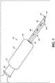
- FIG. 1illustrates an exemplary safety needle device 10 not belonging to the present invention.
- safety needle device 10is comprised of a needle 40, a housing 20, and a retractable sheath 50.
- Housing 20includes a proximal end 22 and a distal end 24 having an opening 26.
- the proximal end of the housingmay be connectable to a luer connection 30 or other fluid connector.
- Retractable sheath 50is slidably mounted and movable in the opening 26 to slidably accommodate and encase needle 40 projecting axially from housing 20.
- the term "retractable sheath"is intended to include any sort of tubular member.
- the retractable sheath 50is dimensioned to be compatible with the size and type of needle 40 as will be appreciated by those skilled in the art.
- the housing 20may include a housing body portion with an internal hollow region (not shown) in which the retractable sheath 50 may move in the proximal direction.
- Needle 40may be connected to a needle hub (not shown) disposed at the proximal end 22 of the housing 20 and having a blunted tip or beveled tip at the distal end.
- the needleis disposed in the needle hub in a manner as would be well understood in the art and which forms no part of the invention.
- the needle hubmay be integrally formed with housing body portion.
- the needle 40extends from the needle hub disposed in the housing 20 to a needle tip and is completely received within the retractable sheath 50 when the retractable sheath 50 is in a distal position.
- the needle tipis exposed from the retractable sheath 50 when the retractable sheath 50 is in a proximal position.
- the retractable sheath 50may include a sheath bevel 54 at the distal end.
- the sheath bevel 54 and needle bevel 48being offset from each other. In one embodiment, the sheath bevel 54 and needle bevel 48 may be offset by 180 degrees.
- retractable sheath 50is generally comprised of a tubular portion and is retractably slidable along the length of the needle 40 such that at least a substantial portion of needle 40 is exposed when the sheath 50 is in its retracted position.
- the length of needle 40 extending outwardly from the needle hub in a distal directionis partially or completely encased when retractable sheath 50 is in its non-retracted position.
- the retractable sheath 50Upon administration of the injection, the retractable sheath 50 moves from a distal to proximal position and the needle tip is exposed so that the needle tip may penetrate the injection site. Upon continued application of force by pressing sheath 50 against the skin at the location where it is desired to insert needle 40, sheath 50 retracts into housing 20 allowing the injection site to be penetrated by the needle tip. When the retractable sheath 50 reaches a fully retracted position (in the proximal most position), the needle reaches a fully extended position, in which the needle tip achieves its maximum penetration of the injection site.
- the practitionerUpon completion of an injection, the practitioner need only withdraw the needle so as to cause the retractable sheath 50 to resiliently return toward the fully extended condition to once again be repositioned to encase needle 40.
- the retractable sheathis connected to the proximal end of the housing by a spring mechanism that acts to resiliently return the retractable sheath toward the fully extended condition.
- Retracting sheath 50may include a bevel formed or cut into the tip at angles ideal for specific injection procedures.
- the ideal injection anglemay be 10-15 degrees therefore, in one or more embodiments of the present invention, the bevel tip would be 10-15 degrees to guide the user at this angle.
- the sheath bevel 54includes at least one injection angle guide configured in the range between 10 to 90 degrees.
- the extreme tip of the injection angle guideis configured as a blunted tip 52 so that perpendicular injections continue to be comfortable to a patient.
- the sheath bevel 54includes at least two injection angle guides wherein a first injection angle guide is configured in the range between 10 to 90 degrees and a second injection angle guide is configured to be larger than the first angle and is in the range between 10 to 90 degrees.
- the first injection angle guidemay be configured as a blunted tip.
- the second injection angle guidemay be configured as a blunted tip.
- a third or more injection angle guidemay be configured as a blunted tip.
- a multi-beveled sheath pointmay be formed through a plurality of individual bevels that together define a beveled face about the periphery of distal end of the retractable sheath.
- the multi-beveled pointis characterized by a primary bevel 62; a secondary bevel 64, and a blunted tip 52.
- the secondary bevel 64is formed on opposite sides of primary bevel 62.
- Primary bevel 62 and secondary bevels 64meet at an intersection "A" shown in Figure 3 demarcating the respective planes at which the primary bevel and secondary bevels are formed. This would allow for almost all common injection techniques, with shallow, medium, and perpendicular injection angles.
- the sheath bevel 54 in one or more embodiments of the inventionis configured to allow for continuously variable injection angles.
- the bevel tipmay be configured in a frusto-conical shape to allow for continuously variable injection angles.
- the sheath bevel 54may also include a rubbery transparent tip.
- the sheath bevel 54may also include a thin, preferably transparent overmold, as shown in Figure 5 .
- the overmoldcan be made of any resilient, flexible material with adequate coefficient of friction with the skin including, but not limited to, rubber.
- Figure 6shows the sheath bevel having a curved contact surface.
- the curved tip of the sheath bevelmay also include a grippy high friction contact surface.
- the material of construction of the high friction contact surfacecan be any resilient, flexible material with adequate coefficient of friction with the skin. Suitable materials include substances such as latex rubber, butyl rubber, silicone, and the like. Alternately, additional materials may be omitted if contact surfaces have sufficient grip.
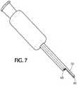
- Figure 7shows the sheath bevel having a blunted tip 60 including an axial projection 70 directed in the distal direction.
- the axial projection of the blunted tipmay also include a nub 80.
- the material of construction of the nub on the axial projectioncan be any resilient, flexible material with adequate coefficient of friction with the skin. Suitable materials for the nub include substances such as latex rubber, butyl rubber, silicone, and the like.
- the tip of 70is the sole point of contact, allowing rotation about that point, and therefore a continuously variable injection angle.
- the injection angle guidemay be fixed or rotatable to adjust the needle bevel angle relative to an injection site. It is believed that most, if not all, common injections are either "bevel up" or non-oriented with respect to bevel.
- the needle bevel 48is oriented in an upward position relative to the injection angle guide and injection angle.
- the sheath bevel 54includes a section of skin-engaging contact surface 56 for increasing the friction between bevel tip and the patient's skin to hold the patient's skin taut prior to an injection.
- the skin-engaging contact surfacefrictionally or adhesively engages and exerts an outward or lateral force on the injection site so that the skin is held taut prior to needle tip puncturing the injection site.
- needle tipmay be extended until needle tip penetrates the skin at the injection site.
- the skin engaging contact surfaceis placed on the bevel tip of the sheath.
- the section of skin-engaging contact surface 56is positioned at a distal end of the sheath bevel.
- the section of skin-engaging contact surface 56may be comprised of a friction enhancing material.
- the material of construction of the skin-engaging contact surfacecan be any resilient, flexible material with adequate coefficient of friction with the skin. Suitable materials include polymeric substances such as latex rubber, butyl rubber, silicone, and the like.
- the skin-engaging contact surfaceworks in combination with the spring force of the sheath to pull the patient's skin taut.
- the needle 40 in accordance with the present inventioncan be formed from conventional materials such as steel or more preferably stainless steel. It will be realized by the skilled artisan that medical grade plastics, composites, ceramics, or like materials can be substituted.
- the bevelscan be formed on the needle 40 by conventional processes such as by grinding.
- the inside diameter of the open-ended retracting sheath 50is selected so that it will fit closely over needle 40 yet will slide freely along the needle 40.
- the retracting sheath 50may be made of any suitable material, but preferably of a polymer which is tough enough to protect needle 40 and may be easily sterilized.
- the materialis preferably transparent or translucent so that the position of needle 40 within retracting sheath 50 can be visually verified.
- Sheath 50is preferably made of a transparent material, so that a health care worker can see the progress of needle 40 as it is emerging from sheath 50 to make sure that it is positioned where desired for an injection.
- the present inventionis also directed to a safety needle device 10 including a housing 20, having a proximal end 22 and a distal end 24 having an opening 26, and a retractable sheath 50 having a graduated injection depth gauge to indicate needle penetration.
- the proximal end of the housingmay be connectable to a luer connection 30 or other fluid connector.
- the retractable sheath 50is disposed and movable in the opening 26 and surrounds a needle 40.
- the retractable sheath 50includes a sheath bevel 54 at the distal end.
- the needle 40may be connected to a needle hub at the proximal end 22 of the housing 20 and may have a needle bevel 48 at the distal end.
- the sheath bevel 54 and needle bevel 48may be offset from each other.
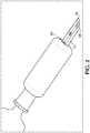
- the retractable sheath 50As injection is performed and needle 40 is inserted into tissue, the retractable sheath 50 is pushed into housing 20. As shown in Figure 1 and 2 , the depth of the needle 40 can be read from the gauge where in enters the hub in the shown embodiment.
- the graduated injection depth gaugemay be printed onto an outer surface of the retractable sheath 50.
- the graduated injection depth gaugemay be engraved, etched, embossed, debossed by molding or formed onto an outer surface of the retractable sheath 50 to assist the practitioner in measuring the needle depth penetration.
- the depth gauge scale in the shown embodimentwould be unique for each needle length.
- the graduated injection depth gaugemay be scaled to correlate to needle length or injection angles.
- the needle penetration depthmay be read from the intersection of the penetration depth markers appearing on the outside of the retractable sheath 50 and the distal end of the housing 24.
- the depth markersmay be arranged so that when the needle 40 is in an initial position, for example, the retractable sheath 50 is in the distal- most position, the position of the needle point relative to the depth markers indicates, for example, the maximum penetration depth of needle tip.
- the safety needle device 10may further include a visual indicator for reading the graduated injection depth gauge, including a magnified readout window, arrow, line or other feature or visible mark printed or formed on the retractable sheath 50.
- a visual indicator for reading the graduated injection depth gaugeincluding a magnified readout window, arrow, line or other feature or visible mark printed or formed on the retractable sheath 50.
- Other visual markersmay also be utilized, for example, symbols and words may be disposed on the retracting sheath 50.
Landscapes
- Health & Medical Sciences (AREA)
- Engineering & Computer Science (AREA)
- Hematology (AREA)
- Anesthesiology (AREA)
- Biomedical Technology (AREA)
- Heart & Thoracic Surgery (AREA)
- Vascular Medicine (AREA)
- Life Sciences & Earth Sciences (AREA)
- Animal Behavior & Ethology (AREA)
- General Health & Medical Sciences (AREA)
- Public Health (AREA)
- Veterinary Medicine (AREA)
- Environmental & Geological Engineering (AREA)
- Infusion, Injection, And Reservoir Apparatuses (AREA)
- Catching Or Destruction (AREA)
Description
- The subject invention relates generally to a safety needle device, and more particularly to a safety needle device having a housing, a retractable sheath, and a needle cannula. The retractable sheath having a tubular portion that is slideably mounted about a portion of the housing to completely or partially encase the length of the cannula. The retractable sheath also having a sheath bevel at the distal end. The sheath bevel having a blunted or angled tip. The angled tip being configured to suitable injection angles and may be fixed or rotatable. The sheath bevel may have a skin-engaging contact surface at the distal end. The needle may be connected to a needle hub at the proximal end of the housing and includes a needle bevel at the distal end. The sheath bevel and needle bevel may be offset from each other. A safety needle device having a retractable sheath having a graduated injection depth gauge to indicate needle penetration is also disclosed.
- Needle devices are used throughout the medical industry for the injection and withdrawal of a wide variety of fluids and solutions into and from the human body. Because of the numerous potential hazards associated with the handling and manipulation of bodily fluids, and particularly blood, there are a number of known safety features that are frequently incorporated into various types of needle devices to protect the practitioner from accidental exposure to the needle.
- Prior retracting sheath safety needle devices have been developed to include a blunt tip suited for injection perpendicular to the injection site. While a blunt tip may be ideal for most intramuscular injections, the administration of other injection techniques, such as intradermal or subcutaneous, may require different injection angles. For example, shallow injection angles are difficult or impossible with existing safety needle devices.
- Prior retracting sheath safety needle devices have been developed to include a single-use cover assembly that obscures a substantial majority or an entirety of an injection needle from view before, during, and after an injection procedure. However, many injection procedures require that the practitioner know precisely the depth to which the needle is inserted in the patient's tissue to be sure that medication is delivered to an appropriate location. Prior retracting sheath safety needle devices do not have depth gauges so that injection depth can be quickly and easily determined.
- There is a need in the art to provide a safety needle device having a sheath tip configured to various different injection angles to facilitate the administration of injection techniques, such as intradermal and subcutaneous, which may require shallow injection angles.
- There is a also need in the art to provide a safety needle device having a depth gauge feature that is capable of quickly and easily determining the injection depth, which is especially useful for certain types of injections, such as intramuscular and subcutaneous.
WO 2011/112916 A1 discloses an assembly for use with a syringe having a barrel and a needle including a sealing element surrounding and positioned over at least a portion of the distal end of the syringe.US 5,256,152 discloses a safety hypodermic needle and a method of using the same.US 2004/0102740 A1 discloses a safety needle including a needle with a sharp end and a needle shield.WO 2008/131440 A1 discloses methods and devices for intradermal administration of diagnostic and therapeutic agents, vaccines and other compounds into the dermal layer of the skin.WO 2004/004803 A2 discloses a device for intradermal delivery having a housing containing a syringe for injecting a substance and a predetermined insertion depth and a base assembly for tensioning a target area of skin.EP 1 066 848 A2 discloses a protective device for injection or aspiration needles, having a barrel piece telescopically slidable over an adapter sleeve mounted at one end to the luer coupling of the syringe or to a multisample collector.WO 02/076526 A2 US 7,744,565 B2 discloses an apparatus for subcutaneous administration of an injectable product.- The subject matter of the invention is defined by independent claim 1.
- The present invention is directed to a safety needle device including a housing having a proximal end and a distal end having an opening. The safety needle device also includes a retractable sheath disposed and movable in the opening and surrounding a needle. The needle may be connected to a needle hub at the proximal end of the housing and having a blunted tip or beveled tip at the distal end. In one or more embodiments, the proximal end of the housing may be connectable to a luer connection or other fluid connector, or integrated into a device such as a syringe. The retractable sheath may include a sheath bevel at the distal end. The sheath bevel and needle bevel being offset from each other. In one embodiment, the sheath bevel and needle bevel may be offset by 180 degrees.
- In one or more embodiments of the present invention, the sheath bevel includes a section of skin-engaging contact surfaces. The section of skin-engaging contact surfaces holds skin taut prior to an injection and may include a friction enhancing material.
- In one or more examples not part of the present invention, the sheath bevel includes at least one injection angle guide configured in the range between 10 to 90 degrees. In one or more embodiments, the injection angle guide may be configured in the range between 5 to 50 degrees. In another embodiment, the injection angle guide is configured as a blunted tip.
- In yet another embodiment, the sheath bevel includes at least two injection angle guides wherein a first injection angle guide is configured in the range between 10 to 90 degrees and a second injection angle guide is configured to be larger than the first angle and is in the range between 10 to 90 degrees. In one or more embodiments, the first injection angle guide is configured as a blunted tip. In one or more embodiments, the second injection angle guide is configured as a blunted tip.
- In one or more embodiments, the injection angle guide may be fixed or rotatable to adjust the needle bevel angle relative to an injection site.
- In one or more embodiments, the sheath bevel may have a frusto-conically shaped tip.
- The frusto-conically shaped tip may be transparent, and may be comprised of a different material and/or may includes a thin transparent overmold. The tip and/or overmold may be made of a material having a high coefficient of friction with skin.
- In one or more embodiments, the sheath bevel may have a curved tip. The curved tip may include a high friction contact surface.
- In one or more embodiments, the sheath bevel may have a blunted tip including an axial projection directed in the distal direction. The axial projection may further include a nub made of a material having a high coefficient of friction with skin.
- The present invention is also directed to a safety needle device including a housing having a proximal end and a distal end having an opening. In one or more embodiments, the proximal end of the housing may be connectable to a luer connection or other fluid connector, or integrated into a device such as a syringe.
- The safety needle device also includes a retractable sheath disposed and movable in the opening and surrounding a needle. The retractable sheath may include a graduated injection depth gauge to indicate needle penetration and a sheath bevel at the distal end. The needle may be connected to a needle hub at the proximal end of the housing and may have a needle bevel at the distal end. The sheath bevel and needle bevel may be offset from each other.
- In one or more embodiments, the graduated injection depth gauge may be printed onto an outer surface of the retractable sheath. In another embodiment, the graduated injection depth gauge may be engraved, etched, embossed, debossed by molding or formed onto an outer surface of the retractable sheath.
- In one or more embodiments, the graduated injection depth gauge may be scaled to correlate to needle length or injection angles. The needle penetration depth may be read from the intersection of the scale and the hub.
- The safety needle device may further include a visual indicator for reading the graduated injection depth gauge, including a magnified window, arrow, line or other feature or visible mark printed or formed on the retractable sheath.
Figure 1 is a perspective view of an example safety needle device not part of the invention, prior to injection in skin.Figure 2 is a perspective view of the example safety needle device after injection into skin.Figure 3 is a perspective view of the safety needle device according to the invention having two bevel guides in accordance with an alternative embodiment of the present invention.Figure 4 is a perspective view of the safety needle device having two bevel guides in accordance with an alternative embodiment of the present invention.Figure 5 is a perspective view of the safety needle device having two bevel guides in accordance with an alternative embodiment of the present invention.Figure 6 is a perspective view of the safety needle device having two bevel guides in accordance with an alternative embodiment of the present invention.Figure 7 is a perspective view of the safety needle device having two bevel guides in accordance with an alternative embodiment of the present invention.- Before describing several exemplary embodiments of the invention, it is to be understood that the invention is not limited to the details of construction or process steps set forth in the following description. The invention is capable of other embodiments and of being practiced or being carried out in various ways.
- In this disclosure, a convention is followed wherein the distal end of the device is the end closest to a patient and the proximal end of the device is the end away from the patient and closest to a practitioner.
Figure 1 illustrates an exemplarysafety needle device 10 not belonging to the present invention. Generally speaking,safety needle device 10 is comprised of aneedle 40, ahousing 20, and aretractable sheath 50.Housing 20 includes aproximal end 22 and adistal end 24 having anopening 26. In one or more embodiments, the proximal end of the housing may be connectable to aluer connection 30 or other fluid connector.Retractable sheath 50 is slidably mounted and movable in theopening 26 to slidably accommodate and encaseneedle 40 projecting axially fromhousing 20. The term "retractable sheath" is intended to include any sort of tubular member. Theretractable sheath 50 is dimensioned to be compatible with the size and type ofneedle 40 as will be appreciated by those skilled in the art. Thehousing 20 may include a housing body portion with an internal hollow region (not shown) in which theretractable sheath 50 may move in the proximal direction.Needle 40 may be connected to a needle hub (not shown) disposed at theproximal end 22 of thehousing 20 and having a blunted tip or beveled tip at the distal end. The needle is disposed in the needle hub in a manner as would be well understood in the art and which forms no part of the invention. The needle hub may be integrally formed with housing body portion. Theneedle 40 extends from the needle hub disposed in thehousing 20 to a needle tip and is completely received within theretractable sheath 50 when theretractable sheath 50 is in a distal position. The needle tip is exposed from theretractable sheath 50 when theretractable sheath 50 is in a proximal position. Theretractable sheath 50 may include asheath bevel 54 at the distal end. Thesheath bevel 54 andneedle bevel 48 being offset from each other. In one embodiment, thesheath bevel 54 andneedle bevel 48 may be offset by 180 degrees.- As illustrated in several of the drawings, most notably
Figure 2 ,retractable sheath 50 is generally comprised of a tubular portion and is retractably slidable along the length of theneedle 40 such that at least a substantial portion ofneedle 40 is exposed when thesheath 50 is in its retracted position. As shown inFigure 1 , the length ofneedle 40 extending outwardly from the needle hub in a distal direction is partially or completely encased whenretractable sheath 50 is in its non-retracted position. - Upon administration of the injection, the
retractable sheath 50 moves from a distal to proximal position and the needle tip is exposed so that the needle tip may penetrate the injection site. Upon continued application of force by pressingsheath 50 against the skin at the location where it is desired to insertneedle 40,sheath 50 retracts intohousing 20 allowing the injection site to be penetrated by the needle tip. When theretractable sheath 50 reaches a fully retracted position (in the proximal most position), the needle reaches a fully extended position, in which the needle tip achieves its maximum penetration of the injection site. Upon completion of an injection, the practitioner need only withdraw the needle so as to cause theretractable sheath 50 to resiliently return toward the fully extended condition to once again be repositioned to encaseneedle 40. In one or more embodiments of the present invention, the retractable sheath is connected to the proximal end of the housing by a spring mechanism that acts to resiliently return the retractable sheath toward the fully extended condition. - Retracting
sheath 50 may include a bevel formed or cut into the tip at angles ideal for specific injection procedures. For example, for intradermal injections the ideal injection angle may be 10-15 degrees therefore, in one or more embodiments of the present invention, the bevel tip would be 10-15 degrees to guide the user at this angle. In one or more embodiments of the present invention, thesheath bevel 54 includes at least one injection angle guide configured in the range between 10 to 90 degrees. In another embodiment, the extreme tip of the injection angle guide is configured as a bluntedtip 52 so that perpendicular injections continue to be comfortable to a patient. - In yet another embodiment of the invention the
sheath bevel 54 includes at least two injection angle guides wherein a first injection angle guide is configured in the range between 10 to 90 degrees and a second injection angle guide is configured to be larger than the first angle and is in the range between 10 to 90 degrees. In one or more embodiments, the first injection angle guide may be configured as a blunted tip. In one or more embodiments, the second injection angle guide may be configured as a blunted tip. In one or more embodiments, a third or more injection angle guide may be configured as a blunted tip. A multi-beveled sheath point may be formed through a plurality of individual bevels that together define a beveled face about the periphery of distal end of the retractable sheath. In one embodiment, the multi-beveled point is characterized by aprimary bevel 62; asecondary bevel 64, and a bluntedtip 52. Thesecondary bevel 64 is formed on opposite sides ofprimary bevel 62.Primary bevel 62 andsecondary bevels 64 meet at an intersection "A" shown inFigure 3 demarcating the respective planes at which the primary bevel and secondary bevels are formed. This would allow for almost all common injection techniques, with shallow, medium, and perpendicular injection angles. - As shown in
Figures 4-7 , it is envisioned that thesheath bevel 54 in one or more embodiments of the invention is configured to allow for continuously variable injection angles. As shown inFigures 4 and5 , the bevel tip may be configured in a frusto-conical shape to allow for continuously variable injection angles. As shown inFigure 4 , thesheath bevel 54 may also include a rubbery transparent tip. Thesheath bevel 54 may also include a thin, preferably transparent overmold, as shown inFigure 5 . The overmold can be made of any resilient, flexible material with adequate coefficient of friction with the skin including, but not limited to, rubber.Figure 6 shows the sheath bevel having a curved contact surface. The curved tip of the sheath bevel may also include a grippy high friction contact surface. The material of construction of the high friction contact surface can be any resilient, flexible material with adequate coefficient of friction with the skin. Suitable materials include substances such as latex rubber, butyl rubber, silicone, and the like. Alternately, additional materials may be omitted if contact surfaces have sufficient grip.Figure 7 shows the sheath bevel having a bluntedtip 60 including anaxial projection 70 directed in the distal direction. The axial projection of the blunted tip may also include anub 80. The material of construction of the nub on the axial projection can be any resilient, flexible material with adequate coefficient of friction with the skin. Suitable materials for the nub include substances such as latex rubber, butyl rubber, silicone, and the like. In this embodiment, the tip of 70 is the sole point of contact, allowing rotation about that point, and therefore a continuously variable injection angle. - In one or more embodiments, the injection angle guide may be fixed or rotatable to adjust the needle bevel angle relative to an injection site. It is believed that most, if not all, common injections are either "bevel up" or non-oriented with respect to bevel. In a preferred embodiment, the
needle bevel 48 is oriented in an upward position relative to the injection angle guide and injection angle. - In certain types of injection technique, it is desirable to pull the patient's skin taut prior to administration of the injection. In one or more embodiments of the present invention, the
sheath bevel 54 includes a section of skin-engagingcontact surface 56 for increasing the friction between bevel tip and the patient's skin to hold the patient's skin taut prior to an injection. Upon contact with the skin of the patient, the skin-engaging contact surface frictionally or adhesively engages and exerts an outward or lateral force on the injection site so that the skin is held taut prior to needle tip puncturing the injection site. At the same time, needle tip may be extended until needle tip penetrates the skin at the injection site. The skin engaging contact surface is placed on the bevel tip of the sheath. In a preferred embodiment, the section of skin-engagingcontact surface 56 is positioned at a distal end of the sheath bevel. The section of skin-engagingcontact surface 56 may be comprised of a friction enhancing material. The material of construction of the skin-engaging contact surface can be any resilient, flexible material with adequate coefficient of friction with the skin. Suitable materials include polymeric substances such as latex rubber, butyl rubber, silicone, and the like. In a preferred embodiment, the skin-engaging contact surface works in combination with the spring force of the sheath to pull the patient's skin taut. - The
needle 40 in accordance with the present invention can be formed from conventional materials such as steel or more preferably stainless steel. It will be realized by the skilled artisan that medical grade plastics, composites, ceramics, or like materials can be substituted. The bevels can be formed on theneedle 40 by conventional processes such as by grinding. - The inside diameter of the open-ended retracting
sheath 50 is selected so that it will fit closely overneedle 40 yet will slide freely along theneedle 40. The retractingsheath 50 may be made of any suitable material, but preferably of a polymer which is tough enough to protectneedle 40 and may be easily sterilized. The material is preferably transparent or translucent so that the position ofneedle 40 within retractingsheath 50 can be visually verified.Sheath 50 is preferably made of a transparent material, so that a health care worker can see the progress ofneedle 40 as it is emerging fromsheath 50 to make sure that it is positioned where desired for an injection. - In another embodiment, the present invention is also directed to a
safety needle device 10 including ahousing 20, having aproximal end 22 and adistal end 24 having anopening 26, and aretractable sheath 50 having a graduated injection depth gauge to indicate needle penetration. In one or more embodiments, the proximal end of the housing may be connectable to aluer connection 30 or other fluid connector. Theretractable sheath 50 is disposed and movable in theopening 26 and surrounds aneedle 40. Theretractable sheath 50 includes asheath bevel 54 at the distal end. Theneedle 40 may be connected to a needle hub at theproximal end 22 of thehousing 20 and may have aneedle bevel 48 at the distal end. Thesheath bevel 54 andneedle bevel 48 may be offset from each other. - As injection is performed and
needle 40 is inserted into tissue, theretractable sheath 50 is pushed intohousing 20. As shown inFigure 1 and2 , the depth of theneedle 40 can be read from the gauge where in enters the hub in the shown embodiment. - In one or more embodiments, the graduated injection depth gauge may be printed onto an outer surface of the
retractable sheath 50. In another embodiment, the graduated injection depth gauge may be engraved, etched, embossed, debossed by molding or formed onto an outer surface of theretractable sheath 50 to assist the practitioner in measuring the needle depth penetration. - The depth gauge scale in the shown embodiment would be unique for each needle length.
- It is envisioned that different injection angles on the same device may require different
scales. For example, in a perpendicular injection, theneedle 40 would enter at a different depth relative to the scale than in a shallow angle. Therefore, it is contemplated that multiple scales may be required if accurate readings are to be taken at different injection angles. - In one or more embodiments, the graduated injection depth gauge may be scaled to correlate to needle length or injection angles. The needle penetration depth may be read from the intersection of the penetration depth markers appearing on the outside of the
retractable sheath 50 and the distal end of thehousing 24. The depth markers may be arranged so that when theneedle 40 is in an initial position, for example, theretractable sheath 50 is in the distal- most position, the position of the needle point relative to the depth markers indicates, for example, the maximum penetration depth of needle tip. - The
safety needle device 10 may further include a visual indicator for reading the graduated injection depth gauge, including a magnified readout window, arrow, line or other feature or visible mark printed or formed on theretractable sheath 50. Other visual markers may also be utilized, for example, symbols and words may be disposed on the retractingsheath 50. - Reference throughout this specification to "one embodiment," "certain embodiments," "one or more embodiments" or "an embodiment" means that a particular feature, structure, material, or characteristic described in connection with the embodiment is included in at least one embodiment of the invention. Thus, the appearances of the phrases such as "in one or more embodiments," "in certain embodiments," "in one embodiment" or "in an embodiment" in various places throughout this specification are not necessarily referring to the same embodiment of the invention. Furthermore, the particular features, structures, materials, or characteristics may be combined in any suitable manner in one or more embodiments.
- Although the invention herein has been described with reference to particular embodiments, it is to be understood that these embodiments are merely illustrative of the principles and applications of the present invention. It will be apparent to those skilled in the art that various modifications and variations can be made to the method and apparatus of the present invention without departing from the scope of the invention. Thus, it is intended that the present invention include modifications and variations that are within the scope of the appended claims and their equivalents.
Claims (17)
- A safety needle device (100) comprising:a housing (20) having a proximal end (22) and a distal end (24) having an opening (26);a retractable sheath (50) disposed and movable in the opening and surrounding a needle (40);the needle (40) connected to a needle hub (80) at the proximal end of the housing and having a needle bevel at the distal end;the retractable sheath (50) having a sheath bevel (54) at the distal end,the sheath bevel having an injection angle guide (58)characterized in thatthe sheath bevel (54) comprises at least two injection angle guides (58) and includes a section of skin-engaging contact surfaces comprised of a friction enhancing material to hold skin taut prior to an injection, the sheath bevel and needle bevel being offset from each other.
- The safety needle device of claim 1, wherein the sheath bevel and needle bevel are offset by 180 degrees.
- The safety needle device of claim 1, wherein the sheath bevel comprises at least one injection angle guide (58) configured in the range between 5 to 90 degrees.
- The safety needle device of claim 3, wherein the at least one injection angle guide is configured as a blunted tip (60).
- The safety needle device of claim 1, wherein a first injection angle guide is configured in the range between 10 to 90 degrees and a second injection angle guide is configured to be larger than the first injection angle and is in the range between 10 to 90 degrees.
- The safety needle device of claim 5, wherein the second injection angle guide is configured as a blunted tip.
- The safety needle device of claim 5, further comprising a third injection angle guide configured as a blunted tip.
- The safety needle device of claim 3, wherein the at least one injection angle guide is rotatable to adjust the needle bevel angle relative to an injection site.
- The safety needle device of claim 1, wherein the sheath bevel has a frusto-conically shaped tip.
- The safety needle device of claim 1, wherein the sheath bevel has a curved tip having a high friction contact surface.
- The safety needle device of claim 1, wherein the sheath bevel comprises a blunted tip having an axial projection directed in the distal direction.
- The safety needle device of claim 11, wherein the axial projection further includes a nub made of a material having a high coefficient of friction with skin.
- The safety needle device of claim 1 further comprising:the retractable sheath having a graduated injection depth gauge to indicate needle penetration depth and a sheath bevel at the distal end;wherein the needle penetration depth can be read from the intersection of the scale and the hub.
- The safety needle device of claim 13, wherein the graduated injection depth gauge is printed, engraved, etched, embossed, or debossed onto an outer surface of the retractable sheath.
- The safety needle device of claim 13, wherein the graduated injection depth gauge is scaled to correlate to needle length or injection angles.
- The safety needle device of claim 13, further comprising a visual indicator for reading the graduated injection depth gauge.
- The safety needle device of claim 16, wherein the indicator is a magnified window.
Priority Applications (1)
| Application Number | Priority Date | Filing Date | Title |
|---|---|---|---|
| EP19203232.4AEP3620193B1 (en) | 2012-03-14 | 2013-03-14 | Angled retracting sheath for safety needle |
Applications Claiming Priority (3)
| Application Number | Priority Date | Filing Date | Title |
|---|---|---|---|
| US201261610576P | 2012-03-14 | 2012-03-14 | |
| US13/793,831US8801680B2 (en) | 2012-03-14 | 2013-03-11 | Angled retracting sheath for safety needle |
| PCT/US2013/031191WO2013138555A2 (en) | 2012-03-14 | 2013-03-14 | Angled retracting sheath for safety needle |
Related Child Applications (2)
| Application Number | Title | Priority Date | Filing Date |
|---|---|---|---|
| EP19203232.4ADivisionEP3620193B1 (en) | 2012-03-14 | 2013-03-14 | Angled retracting sheath for safety needle |
| EP19203232.4ADivision-IntoEP3620193B1 (en) | 2012-03-14 | 2013-03-14 | Angled retracting sheath for safety needle |
Publications (2)
| Publication Number | Publication Date |
|---|---|
| EP2825224A2 EP2825224A2 (en) | 2015-01-21 |
| EP2825224B1true EP2825224B1 (en) | 2019-12-11 |
Family
ID=48040432
Family Applications (2)
| Application Number | Title | Priority Date | Filing Date |
|---|---|---|---|
| EP13713294.0AActiveEP2825224B1 (en) | 2012-03-14 | 2013-03-14 | Angled retracting sheath for safety needle |
| EP19203232.4AActiveEP3620193B1 (en) | 2012-03-14 | 2013-03-14 | Angled retracting sheath for safety needle |
Family Applications After (1)
| Application Number | Title | Priority Date | Filing Date |
|---|---|---|---|
| EP19203232.4AActiveEP3620193B1 (en) | 2012-03-14 | 2013-03-14 | Angled retracting sheath for safety needle |
Country Status (10)
| Country | Link |
|---|---|
| US (2) | US8801680B2 (en) |
| EP (2) | EP2825224B1 (en) |
| JP (2) | JP6240148B2 (en) |
| CN (1) | CN204428535U (en) |
| AU (2) | AU2013232059B2 (en) |
| BR (1) | BR112014022582B1 (en) |
| CA (2) | CA2867152C (en) |
| ES (2) | ES2774290T3 (en) |
| MX (1) | MX349395B (en) |
| WO (1) | WO2013138555A2 (en) |
Cited By (1)
| Publication number | Priority date | Publication date | Assignee | Title |
|---|---|---|---|---|
| EP4255540A4 (en)* | 2021-01-05 | 2024-11-13 | Incyto Co., Ltd. | SLOPE NEEDLE SET AND SLOPE NEEDLE WITH MICRONEEDLE |
Families Citing this family (38)
| Publication number | Priority date | Publication date | Assignee | Title |
|---|---|---|---|---|
| IL152486A0 (en) | 2002-10-25 | 2003-05-29 | Meir Eini | Alcohol-free cosmetic and pharmaceutical foam carrier |
| US9211259B2 (en) | 2002-11-29 | 2015-12-15 | Foamix Pharmaceuticals Ltd. | Antibiotic kit and composition and uses thereof |
| US9668972B2 (en) | 2002-10-25 | 2017-06-06 | Foamix Pharmaceuticals Ltd. | Nonsteroidal immunomodulating kit and composition and uses thereof |
| US8900554B2 (en) | 2002-10-25 | 2014-12-02 | Foamix Pharmaceuticals Ltd. | Foamable composition and uses thereof |
| CA2502986C (en) | 2002-10-25 | 2011-08-23 | Foamix Ltd. | Cosmetic and pharmaceutical foam |
| US7700076B2 (en) | 2002-10-25 | 2010-04-20 | Foamix, Ltd. | Penetrating pharmaceutical foam |
| US7704518B2 (en) | 2003-08-04 | 2010-04-27 | Foamix, Ltd. | Foamable vehicle and pharmaceutical compositions thereof |
| US10117812B2 (en) | 2002-10-25 | 2018-11-06 | Foamix Pharmaceuticals Ltd. | Foamable composition combining a polar solvent and a hydrophobic carrier |
| US20080138296A1 (en) | 2002-10-25 | 2008-06-12 | Foamix Ltd. | Foam prepared from nanoemulsions and uses |
| US7820145B2 (en) | 2003-08-04 | 2010-10-26 | Foamix Ltd. | Oleaginous pharmaceutical and cosmetic foam |
| US9265725B2 (en) | 2002-10-25 | 2016-02-23 | Foamix Pharmaceuticals Ltd. | Dicarboxylic acid foamable vehicle and pharmaceutical compositions thereof |
| US8795693B2 (en) | 2003-08-04 | 2014-08-05 | Foamix Ltd. | Compositions with modulating agents |
| US20080260655A1 (en) | 2006-11-14 | 2008-10-23 | Dov Tamarkin | Substantially non-aqueous foamable petrolatum based pharmaceutical and cosmetic compositions and their uses |
| US8636982B2 (en) | 2007-08-07 | 2014-01-28 | Foamix Ltd. | Wax foamable vehicle and pharmaceutical compositions thereof |
| WO2009069006A2 (en) | 2007-11-30 | 2009-06-04 | Foamix Ltd. | Foam containing benzoyl peroxide |
| WO2009090495A2 (en) | 2007-12-07 | 2009-07-23 | Foamix Ltd. | Oil and liquid silicone foamable carriers and formulations |
| CA2760186C (en) | 2009-04-28 | 2019-10-29 | Foamix Ltd. | Foamable vehicle and pharmaceutical compositions comprising aprotic polar solvents and uses thereof |
| CA2769677A1 (en) | 2009-07-29 | 2011-02-03 | Foamix Ltd. | Non surface active agent non polymeric agent hydro-alcoholic foamable compositions, breakable foams and their uses |
| WO2011013009A2 (en) | 2009-07-29 | 2011-02-03 | Foamix Ltd. | Non surfactant hydro-alcoholic foamable compositions, breakable foams and their uses |
| US8871184B2 (en) | 2009-10-02 | 2014-10-28 | Foamix Ltd. | Topical tetracycline compositions |
| US9849142B2 (en) | 2009-10-02 | 2017-12-26 | Foamix Pharmaceuticals Ltd. | Methods for accelerated return of skin integrity and for the treatment of impetigo |
| US8801680B2 (en)* | 2012-03-14 | 2014-08-12 | Becton, Dickinson And Company | Angled retracting sheath for safety needle |
| USD753289S1 (en) | 2014-03-03 | 2016-04-05 | The Spectranetics Corporation | Sheath |
| USD753290S1 (en) | 2014-03-03 | 2016-04-05 | The Spectranetics Corporation | Sheath set |
| US9675371B2 (en) | 2014-03-03 | 2017-06-13 | The Spectranetics Corporation | Dilator sheath set |
| WO2016077607A1 (en)* | 2014-11-13 | 2016-05-19 | The Regents Of The University Of California | Adjustable stepped cannula |
| WO2016118616A1 (en)* | 2015-01-20 | 2016-07-28 | Talon Medical, LLC | Tissue engagement devices, systems, and methods |
| DE102015111835A1 (en)* | 2015-07-21 | 2017-01-26 | Gerresheimer Regensburg Gmbh | Safety device for a syringe |
| JP6807918B2 (en)* | 2015-09-24 | 2021-01-06 | ベクトン・ディキンソン・アンド・カンパニーBecton, Dickinson And Company | 5 oblique needles of blood collection device |
| WO2017091812A1 (en) | 2015-11-25 | 2017-06-01 | Talon Medical, LLC | Tissue engagement devices, systems, and methods |
| MX377365B (en) | 2016-09-08 | 2025-03-10 | Journey Medical Corp | COMPOSITIONS AND METHODS FOR TREATING ROSACEA AND ACNE. |
| US10765835B2 (en) | 2017-04-05 | 2020-09-08 | Becton, Dickinson And Company | Needle magnetizer |
| RU2681263C1 (en)* | 2017-09-27 | 2019-03-05 | Даниил Васильевич Волков | Syringe tip |
| US12251078B2 (en) | 2018-03-26 | 2025-03-18 | Gyrus Acmi, Inc. | Sheath tip with angled distal face |
| US11266779B2 (en)* | 2019-03-04 | 2022-03-08 | Carefusion 303, Inc. | IV set spike with enhanced removal force |
| KR102384074B1 (en)* | 2020-05-22 | 2022-04-07 | 주식회사 노바메디 | Injection needle apparatus |
| KR102537138B1 (en)* | 2021-04-19 | 2023-05-26 | 경북대학교 산학협력단 | Syringe used to inject anesthetics for framelink stereotatic surgery |
| KR102537121B1 (en)* | 2021-04-19 | 2023-05-26 | 경북대학교 산학협력단 | Syringe with length measuring device |
Citations (1)
| Publication number | Priority date | Publication date | Assignee | Title |
|---|---|---|---|---|
| WO2001091837A1 (en)* | 2000-05-31 | 2001-12-06 | Novo Nordisk A/S | A disposable double pointed injection needle, and an insulin injection system comprising a disposable double pointed injection needle |
Family Cites Families (35)
| Publication number | Priority date | Publication date | Assignee | Title |
|---|---|---|---|---|
| US4178071A (en)* | 1977-10-26 | 1979-12-11 | Asbell Burma B | Magnifying cylinder for insulin syringe |
| US4356822A (en) | 1980-10-17 | 1982-11-02 | Winstead Hall Deborah | Syringe assembly |
| US4775369A (en)* | 1986-09-09 | 1988-10-04 | Boris Schwartz | Automatically actionable sharpened needle-tip protection |
| US4911693A (en)* | 1988-10-17 | 1990-03-27 | Paris Frassetti R | Hypodermic syringe needle guard |
| US5147327A (en)* | 1990-01-10 | 1992-09-15 | Johnson Gerald W | Hypodermic needle with protective sheath |
| US5088986A (en)* | 1990-11-29 | 1992-02-18 | Nusbaum Michael J | Safety syringe |
| US5211628A (en)* | 1991-09-30 | 1993-05-18 | Marshall John M | Syringe with automatic retracting needle |
| US5256152A (en) | 1991-10-29 | 1993-10-26 | Marks Lloyd A | Safety needle and method of using same |
| DE4205036C1 (en)* | 1992-02-19 | 1993-06-17 | Henke-Sass, Wolf Gmbh, 7200 Tuttlingen, De | Injection cylinder for subcutaneous vaccination - comprises first hollow cylindrical tube in which is fitted telescopically second tube with reduced dia. |
| US5242418A (en)* | 1992-05-22 | 1993-09-07 | Weinstein James D | Protective means for a needle or similar cannula medical device |
| US5478328A (en)* | 1992-05-22 | 1995-12-26 | Silverman; David G. | Methods of minimizing disease transmission by used hypodermic needles, and hypodermic needles adapted for carrying out the method |
| US5246428A (en)* | 1992-07-30 | 1993-09-21 | Falknor Donald W | Needle safety mechanism |
| US5312374A (en)* | 1993-03-31 | 1994-05-17 | Simon Gurmarnik | Device for administration of epidural anesthesia |
| US5472430A (en)* | 1993-08-18 | 1995-12-05 | Vlv Associates | Protected needle assembly |
| US5512050A (en)* | 1994-09-20 | 1996-04-30 | Becton, Dickinson And Company | Needle assembly with collapsible and retractable sheath |
| US5487733A (en)* | 1994-09-20 | 1996-01-30 | Becton, Dickinson And Company | Assembly with collapsible sheath and tip guard |
| US5591138A (en)* | 1995-08-10 | 1997-01-07 | Vaillancourt; Vincent L. | Protected needle assembly |
| US5688241A (en)* | 1996-04-15 | 1997-11-18 | Asbaghi; Hooman Ali | Automatic non-reusable needle guard |
| US5895395A (en)* | 1997-07-17 | 1999-04-20 | Yeung; Teresa T. | Partial to full thickness suture device & method for endoscopic surgeries |
| US6309374B1 (en)* | 1998-08-03 | 2001-10-30 | Insite Vision Incorporated | Injection apparatus and method of using same |
| CA2358387C (en)* | 1998-12-31 | 2007-11-13 | Jeffrey E. Yeung | Tissue fastening devices and delivery means |
| DE19925904C1 (en) | 1999-06-07 | 2001-02-01 | Disetronic Licensing Ag | Unit for subcutaneous application of an injectable product comprises a system which indicates whether the protection sleeve of the injection needle is in its fully retracted position |
| US6379336B1 (en)* | 1999-06-18 | 2002-04-30 | Hooman A. Asbaghi | Protective device for injection or aspiration needle |
| US6595955B2 (en) | 2001-03-15 | 2003-07-22 | Specialized Health Products, Inc. | Safety shield for medical needles |
| CA2477220C (en)* | 2002-03-14 | 2007-11-06 | Jeffrey E. Yeung | Suture anchor and approximating device |
| US20040147901A1 (en) | 2002-07-08 | 2004-07-29 | Medical Instill | Intradermal delivery device, and method of intradermal delivery |
| US7083600B2 (en) | 2002-08-08 | 2006-08-01 | Advanced Medical Sharps, Inc. | Safety needle and shield |
| WO2007033077A2 (en)* | 2005-09-12 | 2007-03-22 | Inviro Medical, Inc. | Syringe marking template |
| WO2008131440A1 (en) | 2007-04-23 | 2008-10-30 | Sid Technologies, Llc | Methods and devices for intradermal injection |
| EP2296735A4 (en)* | 2008-05-14 | 2013-05-29 | John Stephens | Needle protective device |
| US20110238038A1 (en) | 2008-12-04 | 2011-09-29 | Nanopass Technologies Ltd. | Intradermal mini - needle interface and associated devices and methods |
| US20110224609A1 (en)* | 2008-12-08 | 2011-09-15 | Sid Technologies, Llc | Alignment of a Needle in an Intradermal Injection Device |
| ES2575546T3 (en) | 2010-03-12 | 2016-06-29 | Sid Technologies Llc | Set for use with a syringe |
| US8162882B2 (en)* | 2010-06-23 | 2012-04-24 | Sta-Med, Llc | Automatic-locking safety needle covers and methods of use and manufacture |
| US8801680B2 (en)* | 2012-03-14 | 2014-08-12 | Becton, Dickinson And Company | Angled retracting sheath for safety needle |
- 2013
- 2013-03-11USUS13/793,831patent/US8801680B2/enactiveActive
- 2013-03-14CNCN201390000435.5Upatent/CN204428535U/ennot_activeExpired - Lifetime
- 2013-03-14ESES13713294Tpatent/ES2774290T3/enactiveActive
- 2013-03-14EPEP13713294.0Apatent/EP2825224B1/enactiveActive
- 2013-03-14ESES19203232Tpatent/ES2953716T3/enactiveActive
- 2013-03-14BRBR112014022582-6Apatent/BR112014022582B1/enactiveIP Right Grant
- 2013-03-14AUAU2013232059Apatent/AU2013232059B2/enactiveActive
- 2013-03-14CACA2867152Apatent/CA2867152C/enactiveActive
- 2013-03-14MXMX2014011003Apatent/MX349395B/enactiveIP Right Grant
- 2013-03-14JPJP2015500594Apatent/JP6240148B2/enactiveActive
- 2013-03-14EPEP19203232.4Apatent/EP3620193B1/enactiveActive
- 2013-03-14CACA2959785Apatent/CA2959785C/enactiveActive
- 2013-03-14WOPCT/US2013/031191patent/WO2013138555A2/enactiveApplication Filing
- 2014
- 2014-06-30USUS14/319,514patent/US10369296B2/enactiveActive
- 2016
- 2016-05-17AUAU2016203190Apatent/AU2016203190B2/enactiveActive
- 2017
- 2017-11-02JPJP2017212994Apatent/JP6640817B2/enactiveActive
Patent Citations (1)
| Publication number | Priority date | Publication date | Assignee | Title |
|---|---|---|---|---|
| WO2001091837A1 (en)* | 2000-05-31 | 2001-12-06 | Novo Nordisk A/S | A disposable double pointed injection needle, and an insulin injection system comprising a disposable double pointed injection needle |
Cited By (1)
| Publication number | Priority date | Publication date | Assignee | Title |
|---|---|---|---|---|
| EP4255540A4 (en)* | 2021-01-05 | 2024-11-13 | Incyto Co., Ltd. | SLOPE NEEDLE SET AND SLOPE NEEDLE WITH MICRONEEDLE |
Also Published As
| Publication number | Publication date |
|---|---|
| EP3620193A2 (en) | 2020-03-11 |
| US20140378910A1 (en) | 2014-12-25 |
| CA2959785A1 (en) | 2013-09-19 |
| AU2016203190A1 (en) | 2016-06-09 |
| ES2774290T3 (en) | 2020-07-20 |
| ES2953716T3 (en) | 2023-11-15 |
| AU2013232059B2 (en) | 2016-03-10 |
| JP6640817B2 (en) | 2020-02-05 |
| US8801680B2 (en) | 2014-08-12 |
| EP3620193B1 (en) | 2023-07-19 |
| JP2018015654A (en) | 2018-02-01 |
| MX349395B (en) | 2017-07-26 |
| EP3620193C0 (en) | 2023-07-19 |
| US10369296B2 (en) | 2019-08-06 |
| JP2015513929A (en) | 2015-05-18 |
| MX2014011003A (en) | 2014-10-13 |
| CN204428535U (en) | 2015-07-01 |
| AU2016203190B2 (en) | 2017-06-15 |
| JP6240148B2 (en) | 2017-11-29 |
| CA2867152C (en) | 2017-04-18 |
| WO2013138555A2 (en) | 2013-09-19 |
| WO2013138555A3 (en) | 2014-04-10 |
| CA2867152A1 (en) | 2013-09-19 |
| BR112014022582B1 (en) | 2021-07-20 |
| EP2825224A2 (en) | 2015-01-21 |
| AU2013232059A1 (en) | 2014-10-09 |
| US20130261565A1 (en) | 2013-10-03 |
| CA2959785C (en) | 2020-07-28 |
| EP3620193A3 (en) | 2020-04-22 |
Similar Documents
| Publication | Publication Date | Title |
|---|---|---|
| EP2825224B1 (en) | Angled retracting sheath for safety needle | |
| KR102205431B1 (en) | Safety needle device | |
| CA2150996C (en) | Needle assembly having single-handedly activatable needle barrier | |
| EP3068472B1 (en) | Access device | |
| CN113891735B (en) | Syringe with flat indicia display surface | |
| CN111936187A (en) | Syringe with flat indicia display surface | |
| CN116059476A (en) | Medical injector | |
| WO2018187517A1 (en) | Multi-point beveled cannula | |
| MXPA97001608A (en) | A syringe of seguri |
Legal Events
| Date | Code | Title | Description |
|---|---|---|---|
| PUAI | Public reference made under article 153(3) epc to a published international application that has entered the european phase | Free format text:ORIGINAL CODE: 0009012 | |
| 17P | Request for examination filed | Effective date:20140919 | |
| AK | Designated contracting states | Kind code of ref document:A2 Designated state(s):AL AT BE BG CH CY CZ DE DK EE ES FI FR GB GR HR HU IE IS IT LI LT LU LV MC MK MT NL NO PL PT RO RS SE SI SK SM TR | |
| AX | Request for extension of the european patent | Extension state:BA ME | |
| DAX | Request for extension of the european patent (deleted) | ||
| RAP1 | Party data changed (applicant data changed or rights of an application transferred) | Owner name:BECTON, DICKINSON AND COMPANY | |
| STAA | Information on the status of an ep patent application or granted ep patent | Free format text:STATUS: EXAMINATION IS IN PROGRESS | |
| 17Q | First examination report despatched | Effective date:20170411 | |
| GRAP | Despatch of communication of intention to grant a patent | Free format text:ORIGINAL CODE: EPIDOSNIGR1 | |
| STAA | Information on the status of an ep patent application or granted ep patent | Free format text:STATUS: GRANT OF PATENT IS INTENDED | |
| INTG | Intention to grant announced | Effective date:20190705 | |
| GRAS | Grant fee paid | Free format text:ORIGINAL CODE: EPIDOSNIGR3 | |
| GRAA | (expected) grant | Free format text:ORIGINAL CODE: 0009210 | |
| STAA | Information on the status of an ep patent application or granted ep patent | Free format text:STATUS: THE PATENT HAS BEEN GRANTED | |
| AK | Designated contracting states | Kind code of ref document:B1 Designated state(s):AL AT BE BG CH CY CZ DE DK EE ES FI FR GB GR HR HU IE IS IT LI LT LU LV MC MK MT NL NO PL PT RO RS SE SI SK SM TR | |
| REG | Reference to a national code | Ref country code:GB Ref legal event code:FG4D | |
| REG | Reference to a national code | Ref country code:CH Ref legal event code:EP | |
| REG | Reference to a national code | Ref country code:AT Ref legal event code:REF Ref document number:1211543 Country of ref document:AT Kind code of ref document:T Effective date:20191215 | |
| REG | Reference to a national code | Ref country code:DE Ref legal event code:R096 Ref document number:602013063854 Country of ref document:DE | |
| REG | Reference to a national code | Ref country code:IE Ref legal event code:FG4D | |
| REG | Reference to a national code | Ref country code:NL Ref legal event code:MP Effective date:20191211 | |
| REG | Reference to a national code | Ref country code:LT Ref legal event code:MG4D | |
| PG25 | Lapsed in a contracting state [announced via postgrant information from national office to epo] | Ref country code:FI Free format text:LAPSE BECAUSE OF FAILURE TO SUBMIT A TRANSLATION OF THE DESCRIPTION OR TO PAY THE FEE WITHIN THE PRESCRIBED TIME-LIMIT Effective date:20191211 Ref country code:BG Free format text:LAPSE BECAUSE OF FAILURE TO SUBMIT A TRANSLATION OF THE DESCRIPTION OR TO PAY THE FEE WITHIN THE PRESCRIBED TIME-LIMIT Effective date:20200311 Ref country code:SE Free format text:LAPSE BECAUSE OF FAILURE TO SUBMIT A TRANSLATION OF THE DESCRIPTION OR TO PAY THE FEE WITHIN THE PRESCRIBED TIME-LIMIT Effective date:20191211 Ref country code:LV Free format text:LAPSE BECAUSE OF FAILURE TO SUBMIT A TRANSLATION OF THE DESCRIPTION OR TO PAY THE FEE WITHIN THE PRESCRIBED TIME-LIMIT Effective date:20191211 Ref country code:NO Free format text:LAPSE BECAUSE OF FAILURE TO SUBMIT A TRANSLATION OF THE DESCRIPTION OR TO PAY THE FEE WITHIN THE PRESCRIBED TIME-LIMIT Effective date:20200311 Ref country code:LT Free format text:LAPSE BECAUSE OF FAILURE TO SUBMIT A TRANSLATION OF THE DESCRIPTION OR TO PAY THE FEE WITHIN THE PRESCRIBED TIME-LIMIT Effective date:20191211 Ref country code:GR Free format text:LAPSE BECAUSE OF FAILURE TO SUBMIT A TRANSLATION OF THE DESCRIPTION OR TO PAY THE FEE WITHIN THE PRESCRIBED TIME-LIMIT Effective date:20200312 | |
| PG25 | Lapsed in a contracting state [announced via postgrant information from national office to epo] | Ref country code:HR Free format text:LAPSE BECAUSE OF FAILURE TO SUBMIT A TRANSLATION OF THE DESCRIPTION OR TO PAY THE FEE WITHIN THE PRESCRIBED TIME-LIMIT Effective date:20191211 Ref country code:RS Free format text:LAPSE BECAUSE OF FAILURE TO SUBMIT A TRANSLATION OF THE DESCRIPTION OR TO PAY THE FEE WITHIN THE PRESCRIBED TIME-LIMIT Effective date:20191211 | |
| PG25 | Lapsed in a contracting state [announced via postgrant information from national office to epo] | Ref country code:AL Free format text:LAPSE BECAUSE OF FAILURE TO SUBMIT A TRANSLATION OF THE DESCRIPTION OR TO PAY THE FEE WITHIN THE PRESCRIBED TIME-LIMIT Effective date:20191211 | |
| REG | Reference to a national code | Ref country code:ES Ref legal event code:FG2A Ref document number:2774290 Country of ref document:ES Kind code of ref document:T3 Effective date:20200720 | |
| PG25 | Lapsed in a contracting state [announced via postgrant information from national office to epo] | Ref country code:EE Free format text:LAPSE BECAUSE OF FAILURE TO SUBMIT A TRANSLATION OF THE DESCRIPTION OR TO PAY THE FEE WITHIN THE PRESCRIBED TIME-LIMIT Effective date:20191211 Ref country code:RO Free format text:LAPSE BECAUSE OF FAILURE TO SUBMIT A TRANSLATION OF THE DESCRIPTION OR TO PAY THE FEE WITHIN THE PRESCRIBED TIME-LIMIT Effective date:20191211 Ref country code:NL Free format text:LAPSE BECAUSE OF FAILURE TO SUBMIT A TRANSLATION OF THE DESCRIPTION OR TO PAY THE FEE WITHIN THE PRESCRIBED TIME-LIMIT Effective date:20191211 Ref country code:CZ Free format text:LAPSE BECAUSE OF FAILURE TO SUBMIT A TRANSLATION OF THE DESCRIPTION OR TO PAY THE FEE WITHIN THE PRESCRIBED TIME-LIMIT Effective date:20191211 Ref country code:PT Free format text:LAPSE BECAUSE OF FAILURE TO SUBMIT A TRANSLATION OF THE DESCRIPTION OR TO PAY THE FEE WITHIN THE PRESCRIBED TIME-LIMIT Effective date:20200506 | |
| PG25 | Lapsed in a contracting state [announced via postgrant information from national office to epo] | Ref country code:SK Free format text:LAPSE BECAUSE OF FAILURE TO SUBMIT A TRANSLATION OF THE DESCRIPTION OR TO PAY THE FEE WITHIN THE PRESCRIBED TIME-LIMIT Effective date:20191211 Ref country code:IS Free format text:LAPSE BECAUSE OF FAILURE TO SUBMIT A TRANSLATION OF THE DESCRIPTION OR TO PAY THE FEE WITHIN THE PRESCRIBED TIME-LIMIT Effective date:20200411 Ref country code:SM Free format text:LAPSE BECAUSE OF FAILURE TO SUBMIT A TRANSLATION OF THE DESCRIPTION OR TO PAY THE FEE WITHIN THE PRESCRIBED TIME-LIMIT Effective date:20191211 | |
| REG | Reference to a national code | Ref country code:DE Ref legal event code:R097 Ref document number:602013063854 Country of ref document:DE | |
| REG | Reference to a national code | Ref country code:AT Ref legal event code:MK05 Ref document number:1211543 Country of ref document:AT Kind code of ref document:T Effective date:20191211 | |
| PLBE | No opposition filed within time limit | Free format text:ORIGINAL CODE: 0009261 | |
| STAA | Information on the status of an ep patent application or granted ep patent | Free format text:STATUS: NO OPPOSITION FILED WITHIN TIME LIMIT | |
| PG25 | Lapsed in a contracting state [announced via postgrant information from national office to epo] | Ref country code:DK Free format text:LAPSE BECAUSE OF FAILURE TO SUBMIT A TRANSLATION OF THE DESCRIPTION OR TO PAY THE FEE WITHIN THE PRESCRIBED TIME-LIMIT Effective date:20191211 Ref country code:MC Free format text:LAPSE BECAUSE OF FAILURE TO SUBMIT A TRANSLATION OF THE DESCRIPTION OR TO PAY THE FEE WITHIN THE PRESCRIBED TIME-LIMIT Effective date:20191211 | |
| REG | Reference to a national code | Ref country code:CH Ref legal event code:PL | |
| 26N | No opposition filed | Effective date:20200914 | |
| PG25 | Lapsed in a contracting state [announced via postgrant information from national office to epo] | Ref country code:SI Free format text:LAPSE BECAUSE OF FAILURE TO SUBMIT A TRANSLATION OF THE DESCRIPTION OR TO PAY THE FEE WITHIN THE PRESCRIBED TIME-LIMIT Effective date:20191211 Ref country code:AT Free format text:LAPSE BECAUSE OF FAILURE TO SUBMIT A TRANSLATION OF THE DESCRIPTION OR TO PAY THE FEE WITHIN THE PRESCRIBED TIME-LIMIT Effective date:20191211 Ref country code:PL Free format text:LAPSE BECAUSE OF FAILURE TO SUBMIT A TRANSLATION OF THE DESCRIPTION OR TO PAY THE FEE WITHIN THE PRESCRIBED TIME-LIMIT Effective date:20191211 | |
| PG25 | Lapsed in a contracting state [announced via postgrant information from national office to epo] | Ref country code:LU Free format text:LAPSE BECAUSE OF NON-PAYMENT OF DUE FEES Effective date:20200314 | |
| PG25 | Lapsed in a contracting state [announced via postgrant information from national office to epo] | Ref country code:LI Free format text:LAPSE BECAUSE OF NON-PAYMENT OF DUE FEES Effective date:20200331 Ref country code:IE Free format text:LAPSE BECAUSE OF NON-PAYMENT OF DUE FEES Effective date:20200314 Ref country code:CH Free format text:LAPSE BECAUSE OF NON-PAYMENT OF DUE FEES Effective date:20200331 | |
| PG25 | Lapsed in a contracting state [announced via postgrant information from national office to epo] | Ref country code:TR Free format text:LAPSE BECAUSE OF FAILURE TO SUBMIT A TRANSLATION OF THE DESCRIPTION OR TO PAY THE FEE WITHIN THE PRESCRIBED TIME-LIMIT Effective date:20191211 Ref country code:MT Free format text:LAPSE BECAUSE OF FAILURE TO SUBMIT A TRANSLATION OF THE DESCRIPTION OR TO PAY THE FEE WITHIN THE PRESCRIBED TIME-LIMIT Effective date:20191211 Ref country code:CY Free format text:LAPSE BECAUSE OF FAILURE TO SUBMIT A TRANSLATION OF THE DESCRIPTION OR TO PAY THE FEE WITHIN THE PRESCRIBED TIME-LIMIT Effective date:20191211 | |
| PG25 | Lapsed in a contracting state [announced via postgrant information from national office to epo] | Ref country code:MK Free format text:LAPSE BECAUSE OF FAILURE TO SUBMIT A TRANSLATION OF THE DESCRIPTION OR TO PAY THE FEE WITHIN THE PRESCRIBED TIME-LIMIT Effective date:20191211 | |
| PGFP | Annual fee paid to national office [announced via postgrant information from national office to epo] | Ref country code:DE Payment date:20250218 Year of fee payment:13 | |
| PGFP | Annual fee paid to national office [announced via postgrant information from national office to epo] | Ref country code:BE Payment date:20250218 Year of fee payment:13 | |
| PGFP | Annual fee paid to national office [announced via postgrant information from national office to epo] | Ref country code:FR Payment date:20250219 Year of fee payment:13 | |
| PGFP | Annual fee paid to national office [announced via postgrant information from national office to epo] | Ref country code:IT Payment date:20250218 Year of fee payment:13 Ref country code:GB Payment date:20250220 Year of fee payment:13 | |
| PGFP | Annual fee paid to national office [announced via postgrant information from national office to epo] | Ref country code:ES Payment date:20250401 Year of fee payment:13 |