EP2823796B1 - Wheelchair with tilt capability - Google Patents
Wheelchair with tilt capabilityDownload PDFInfo
- Publication number
- EP2823796B1 EP2823796B1EP13176357.5AEP13176357AEP2823796B1EP 2823796 B1EP2823796 B1EP 2823796B1EP 13176357 AEP13176357 AEP 13176357AEP 2823796 B1EP2823796 B1EP 2823796B1
- Authority
- EP
- European Patent Office
- Prior art keywords
- arm
- tilt
- lifting member
- electric wheelchair
- tilt frame
- Prior art date
- Legal status (The legal status is an assumption and is not a legal conclusion. Google has not performed a legal analysis and makes no representation as to the accuracy of the status listed.)
- Active
Links
Images


Classifications
- A—HUMAN NECESSITIES
- A61—MEDICAL OR VETERINARY SCIENCE; HYGIENE
- A61G—TRANSPORT, PERSONAL CONVEYANCES, OR ACCOMMODATION SPECIALLY ADAPTED FOR PATIENTS OR DISABLED PERSONS; OPERATING TABLES OR CHAIRS; CHAIRS FOR DENTISTRY; FUNERAL DEVICES
- A61G5/00—Chairs or personal conveyances specially adapted for patients or disabled persons, e.g. wheelchairs
- A61G5/04—Chairs or personal conveyances specially adapted for patients or disabled persons, e.g. wheelchairs motor-driven
- A—HUMAN NECESSITIES
- A47—FURNITURE; DOMESTIC ARTICLES OR APPLIANCES; COFFEE MILLS; SPICE MILLS; SUCTION CLEANERS IN GENERAL
- A47C—CHAIRS; SOFAS; BEDS
- A47C1/00—Chairs adapted for special purposes
- A47C1/02—Reclining or easy chairs
- A—HUMAN NECESSITIES
- A61—MEDICAL OR VETERINARY SCIENCE; HYGIENE
- A61G—TRANSPORT, PERSONAL CONVEYANCES, OR ACCOMMODATION SPECIALLY ADAPTED FOR PATIENTS OR DISABLED PERSONS; OPERATING TABLES OR CHAIRS; CHAIRS FOR DENTISTRY; FUNERAL DEVICES
- A61G5/00—Chairs or personal conveyances specially adapted for patients or disabled persons, e.g. wheelchairs
- A61G5/10—Parts, details or accessories
- A61G5/1056—Arrangements for adjusting the seat
- A61G5/1059—Arrangements for adjusting the seat adjusting the height of the seat
- A—HUMAN NECESSITIES
- A61—MEDICAL OR VETERINARY SCIENCE; HYGIENE
- A61G—TRANSPORT, PERSONAL CONVEYANCES, OR ACCOMMODATION SPECIALLY ADAPTED FOR PATIENTS OR DISABLED PERSONS; OPERATING TABLES OR CHAIRS; CHAIRS FOR DENTISTRY; FUNERAL DEVICES
- A61G5/00—Chairs or personal conveyances specially adapted for patients or disabled persons, e.g. wheelchairs
- A61G5/10—Parts, details or accessories
- A61G5/1056—Arrangements for adjusting the seat
- A61G5/1075—Arrangements for adjusting the seat tilting the whole seat backwards
- B—PERFORMING OPERATIONS; TRANSPORTING
- B60—VEHICLES IN GENERAL
- B60N—SEATS SPECIALLY ADAPTED FOR VEHICLES; VEHICLE PASSENGER ACCOMMODATION NOT OTHERWISE PROVIDED FOR
- B60N2/00—Seats specially adapted for vehicles; Arrangement or mounting of seats in vehicles
- B60N2/02—Seats specially adapted for vehicles; Arrangement or mounting of seats in vehicles the seat or part thereof being movable, e.g. adjustable
- B60N2/04—Seats specially adapted for vehicles; Arrangement or mounting of seats in vehicles the seat or part thereof being movable, e.g. adjustable the whole seat being movable
- B60N2/10—Seats specially adapted for vehicles; Arrangement or mounting of seats in vehicles the seat or part thereof being movable, e.g. adjustable the whole seat being movable tiltable
Definitions
- the present disclosuregenerally relates to a wheelchair and in particular to a wheelchair arranged to enable tilt of the wheelchair seat.
- Electric wheelchairsare commonly fitted with a tilt arrangement which allows adjustment of the orientation and/or the height of the wheelchair seat.
- Such adjustmentmay be anterior, i.e. forward, posterior, i.e. backwards, tilting and/or lifting of the seat.
- a seat occupant or caretakermay thereby for example set the seat position according to desire or current need of the occupant.
- adjustment of the seat orientationmay be a desirable feature for control purposes to stabilise the wheelchair depending on speed and travel on inclined surfaces.
- EP1997466discloses a wheelchair which provides posterior tilt, anterior tilt, full standing anterior tilt and lift.
- the wheelchaircomprises a plurality of interacting actuators and levers.
- a first actuatoris arranged to actuate a pivotable lever which is provided with a second actuator. Interaction between the first actuator and the pivotable lever provides posterior tilt, and further interaction with the second actuator enables lift and anterior tilt.
- CH 697 181discloses a seating unit for use in wheelchairs.
- the seating unitsits on a carriage frame and is built as a separate unit from the frame.
- the seating unitcomprises a seating surface, a back support and leg supports on an upright frame and can be adjusted via a first aggregate or manually adjustable upright mechanism for lifting the upright frame in a standing position or lowering it to a seating position.
- a general object of the present disclosureis to provide a wheelchair which solves or at least mitigates the problems of the prior art.
- an electric wheelchaircomprising: a chassis; a lift device having a base member which is fixedly arranged to the chassis, and a lifting member arranged to move rectilinearly relative to the base member along an axis defined by a longitudinal extension of the lifting member, wherein the lifting member is arranged to move between a retracted position and an extended position; a tilt frame, a first arm pivotally coupled to the lifting member and the tilt frame, and a second arm coupled to the base member, and which second arm is pivotally coupled to the first arm forming a pivot connection, wherein movement of the lifting member towards the extended position moves the pivot connection towards the base member and movement of the lifting member towards the retracted position moves the pivot connection away from the base member.
- An effect which may be obtainable by the pivotal coupling between the lifting member and the first arm, and the pivotal coupling of the first arm and the second arm which forms a pivot connection that is moveable relative to the base memberis that adjustment of the orientation of the tilt frame provides less change of the point of gravity of a wheelchair occupant thus rendering the electric wheelchair more stable during tilt, especially during posterior tilt.
- a more compact tilt arrangementmay be provided compared to the prior art, providing more flexibility for battery placement on the chassis.
- the pivotal coupling of the first arm with the lifting member and the pivotal coupling of the first arm with the tilt frameare spaced apart.
- One embodimentcomprises a distancing member arranged to distance the first arm from the tilt frame.
- a pivot axis defined by the pivotal coupling of the first arm with the lifting memberis perpendicular to and offset from the axis defined by the longitudinal extension of the lifting member.
- the first armforms a linkage comprising a first portion and a second portion, wherein the first portion extends between the coupling with the second arm and the coupling with the lifting member, and the second portion extends between the coupling with the lifting member and the coupling with the tilt frame.
- the first portiononly extends at a first side of the axis defined by the longitudinal extension of the lifting member.
- the second portionintersects the axis defined by the longitudinal extension of the lifting member.
- the first armis coupled to the lifting member at an end portion of the lifting member.
- the distancing memberis pivotally coupled to the first arm.
- the distancing memberis pivotally coupled to the tilt frame.
- the distancing memberis a tilt actuator extendable to increase the distance between the first arm and the tilt frame.
- One embodimentcomprises a standing actuator arranged to move, in a plane defined by the tilt frame, an end of the distancing member which is coupled to the tilt frame.
- the second armis fixedly arranged to the base member.
- the pivotal coupling between the first arm and the second armis defined by a slidable connection.
- the second armis pivotally coupled to the base member, and wherein the first arm and the second arm are pivotally coupled to each other.
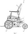
- Fig. 1depicts a schematic side view of an example of an electric wheelchair 1.
- the wheelchair 1comprises a chassis 3, a seat 5, wheels 7a and 7b and a tilt arrangement 9 on which the seat 5 is arranged.
- the exemplified wheelchair 1is of front wheel drive type. It should however be noted that the wheelchair could be of any wheel drive type such as midwheel drive type, back wheel drive type, four wheel drive type or six wheel drive type.
- the electric wheelchair 1comprises a battery and a motor which are attached to the chassis 3.
- the batterymay be electrically coupled to the motor wherein the motor is mechanically coupled to the wheels 7a and 7b for driving the electric wheelchair 1.
- the tilt arrangement 9may be operable by means of the motor and may, depending on the particular implementation, provide one of anterior tilt, posterior tilt, full standing tilt, and lift, or a combination of anterior/posterior tilt, full standing tilt and lift, as will be explained in this disclosure.
- Fig. 1the tilt arrangement 9 is in a lowered, folded state.
- Fig. 2depicts a first example of a tilt arrangement 9a.
- the tilt arrangement 9aWhen properly mounted to the chassis 3 of the electric wheelchair 1, the tilt arrangement 9a enables posterior tilt, i.e. backwards tilt of the seat 5.
- the tilt arrangement 9acomprises a lift device 11.
- the lift device 11has a base member 11a arranged to be fixed to the chassis 3.
- the lift device 11has a lifting member 11b arranged to move rectilinearly relative to the base member 11a, along an axis 11c defined by the longitudinal extension of the lifting member 11b.
- the base member 11amay for example be arranged to accommodate the lifting member 11b such that the lifting member 11b may run in the base member 11a.
- the lifting member 11bis arranged to move rectilinearly between a lowered position in which the lifting member 11b is retracted relative to the base member 11a, and an elevated or lifted position in which the lifting member 11b is extended relative to the base member 11a. Actuation of the lifting member 11b may for example be performed by means of the motor of the electric wheelchair 1.
- the tilt arrangement 9afurther comprises a first arm 13, a second arm 15 and a tilt frame 17.
- the tilt frame 17is arranged to support a seat.
- the first arm 13is pivotally coupled to an end portion 11d of the lifting member 11b and slidably connected to the second arm 15.
- the first arm 13is furthermore pivotally coupled to the tilt frame 17 forming a tilt joint 14.
- the second arm 15is fixedly arranged to the base member 11a.
- the second arm 15has a proximal end 15a and a distal end 15b, wherein the proximal end 15a is fixedly attached to the base member 11a and the distal end 15b which faces away from the base member 11a may form a free end.
- a pivot axisi.e. the tilt joint 14, defined by the pivotal coupling of the first arm 13 with the lifting member 11b is perpendicular to and offset from the axis 11c defined by the longitudinal extension of the lifting member 11b.
- the tilt joint 14is hence distanced from the axis 11c, on a first side of the lifting member 11b, which is the side at which the second arm 15 extends, in a direction from the proximal end 15a to the distal end 15b, from the base member 11a.
- the pivot axismay alternatively be aligned with the axis defined by the longitudinal extension of the lifting member, for example by providing the pivotal coupling between the first arm and the lifting member at the distal end face, i.e. the top, of the lifting member.
- the second armhas a slot 15c which extends between the proximal end 15a and the distal end 15b.
- the slot 15cis perpendicular or essentially perpendicular to the base member 11a and thus the axis 11c.
- the first arm 13has a slot interaction member 13a slidably arranged in the slot 15c such that the first arm 13 may slide between the two ends of the slot 15c.
- the length of the slot 15cis dimensioned such that when the lifting member 11b is maximally retracted and in the lowered state, the slot interaction member 13a is located at a distal slot end with respect to the base member 11a and when the lifting member is maximally extended and in the elevated or lifted position the slot interaction member 13a is located at a proximal slot end with respect to the base member 11a.
- the slot interaction member 13ahence provides a translatable pivot point of the first arm 13 relative to the second arm 15.
- the tilt arrangement 9aforms a tilt mechanism.
- the tilt frame 17is essentially perpendicular to the axis 11c and the base member 11a when the lifting member 11b is maximally retracted. When tilting, the tilt frame 17 tilts with an angle which is dependent of the amount of extension of the lifting member 11b.
- the tilt arrangementmay according to one variation comprise a distancing member 19, as shown in Fig. 3a which depicts a tilt arrangement 9a'.
- the distancing member 19is arranged to distance the first arm 13 from the tilt frame 17, especially that end of the tilt frame 17 which is farthest away from the lifting member 11a to thereby obtain a tilt frame which is essentially parallel with the slot 15c when the lifting member 11b is maximally retracted.
- tilt arrangement 9a'which is identical in operation to tilt arrangement 9a, will now be described with reference to Figs 3a and 3b .
- the tilt arrangement 9a'is in a folded or lowered position A in which the lifting member 11b is fully retracted and the slot interaction member 13a of the first arm 13 is arranged at a distal slot end 15d of slot 15c.
- a distancing member 19is arranged to distance the first arm 13 from the tilt frame 17.
- the distancing member 19is arranged to maintain an essentially perpendicular position of the tilt frame 17 relative to the base member 11a and an essentially parallel position relative to the second arm 15 when the tilt arrangement 9a' is in the lowered position A.
- Fig. 3bthe lifting member 11b has been moved rectilinearly relative to the base member 11a such that the lifting member 11b has attained its maximal elevated or lifted position.
- the tilt arrangement 9a'thus obtains a maximal tilting position B.
- Posterior tilt of the tilt frame 17is thus obtained.
- the slot interaction member 13amoves continually along the slot 15c from the distal slot end 15d towards a proximal slot end 15e.
- the tilt arrangement 9aattains its maximal tilting position B.
- the slot interaction member 13amay be fixed at any position between the distal slot end 15d and the proximal slot end 15e to obtain any inclination of the tilt frame 17 between folded or lowered position A and the maximal tilting position B.
- the position of the slot interaction member 13ais determined by the amount of the extension of the lifting member 11b relative to the base member 11a, and may for example be controlled by means of the motor of the wheelchair.
- Tilt arrangement 9bis in many ways identical to tilt arrangements 9a and 9a' previously described.
- the tilt arrangement 9bhas additional functionality compared to tilt arrangements 9a, 9a'.
- Tilt arrangement 9bcan additionally provide anterior tilt, i.e. forward tilt, and lift of the tilt frame 17, and thus of a seat mounted to the tilt frame 17.
- Tilt arrangement 9bcomprises a distancing member 19' sin the form of a tilt actuator arranged to move rectilinearly between a retracted position and an extended position.
- the tilt actuatormay for example be a hydraulic, pneumatic, electrical or a mechanical actuator, or a combination of two or more of the mentioned types of actuators.
- the distancing member 19'is pivotally coupled to the tilt frame 17 forming a pivot joint 19a, and to the lifting member 11b or the first arm 13 forming a pivot joint 19b.
- the pivotal coupling of the first arm 13 with the lifting member 11b and the pivotal coupling of the first arm 13 with the tilt frame 17are spaced apart.
- the first arm 13forms a linkage comprising a first portion 13f and a second portion 13g.
- the first portion 13fextends between the pivotal coupling of the first arm 13 with the second arm 15 and the pivotal coupling of the first arm 13 with the lifting member 11b.
- the second portion 13gextends between the pivotal coupling of the first arm 13 with the lifting member 11b and the pivotal coupling of the first arm 13 with the tilt frame 17.
- the coupling between the second portion 13g and the tilt frame 17forms a pivot joint 13h.
- the second portion 13g and the tilt frame 17are pivotally coupled at a respective end forming an angle ⁇ therebetween. The angle ⁇ can be varied by means of the distancing member 19' between about 0° to about 90°.
- the first portion 13fonly extends at a first side of the axis 11c defined by the longitudinal extension of the lifting member 11b, or at least has its main extension at the first side of the axis 11c.
- the coupling between the first arm 13 and the lifting member 11bis provided at the first side of the axis 11c, i.e. that side of the base member 11a from which the second arm 15 extends towards its distal end 15b.
- the second portion 13gintersects the axis 11c and thus extends beyond the lifting member 11b.
- the amount of tiltmay be defined.
- additional liftcompared to that lift provided by the lifting member 11b may be provided.
- the tilt arrangement 9bis in the folded or lowered position A.
- the slot interaction member 13ais positioned at, or close to, the distal slot end 15d of the slot 15c of the second arm 15.
- the slot interaction member 13ahas been moved from the distal slot end 15d towards the proximal slot end 15e as the lifting member 11b has moved rectilinearly towards its maximally extended position.
- the tilt arrangement 9bhence obtains a tilted position A', which is a posterior tilt.
- Fig. 5cdepicts an anterior tilt position C of the tilt arrangement 9b.
- the angles of the distancing member 19' at the pivoting joints 19a and 19b, the extension of the distancing member 19', and the position of the lifting member 11bdetermines the amount of anterior tilt.
- the distancing member 19' or tilt actuatoris in its maximal extended position, and when an angle ⁇ between the distancing member 19' and the first arm 13 in a direction from the slot interaction member 13a towards the coupling between the first arm 13 and the lifting member 11b is maximal, the tilt frame 17 is subjected to maximal anterior tilt.
- Actuation of the distancing member 19' between its maximal retraced and extended positionsadjusts the angle ⁇ between the tilt frame 17 and the first arm 13 at the pivot joint 13h. Adjustment of the angle ⁇ between the distancing member 19' and the first arm 13 also adjusts the angle ⁇ between the tilt frame 17 and the first arm 13 at the pivot joint 13h.
- the tilt arrangement 9bis in an elevated or lifted state D.
- the elevated or lifted state Dis obtained by extending the lifting member 11b and by extending the distancing member 19'.
- the tilt frame 17may thereby be arranged essentially perpendicular to the axis 11c illustrated in Fig. 2 and defined by the longitudinal extension of the lifting member 11b.
- the tilt frame 17is hence parallel with or essentially parallel with the slot 15c.
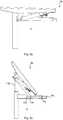
- Fig. 6shows a third example of a tilt arrangement.
- Tilt arrangement 9cis in many ways identical to tilt arrangement 9b but provides the additional functionality of full standing position of the tilt frame.
- Tilt arrangement 9cfurther comprises a standing actuator 21.
- the standing actuator 21is arranged to move or translate, in a plane defined by tilt frame 17', that end of the distancing member 19' which is pivotally coupled to the tilt frame 17'.
- the standing actuatormay be arranged in the tilt frame 17' and arranged to provide a rectilinear motion in the plane defined by the tilt frame 17'.
- the standing actuator 21is arranged to move between a first position P1 in which anterior tilt of the tilt frame 17 may be provided in combination with proper positioning of the lifting member 11b and the distancing member 19', and a second position P2 in which a full anterior standing position of the tilt frame 17 may be obtained.
- the first position P1is farther away from the axis 11c and the pivotable coupling between the first arm 13 and the tilt frame 17 than the second position P2.
- a longitudinal section of the tilt arrangement 9cis shown.
- the tilt frame 17'is set in a full standing position E.
- the standing actuator 21has translated one end of the distancing member 19' from the first position P1 to the second position P2 in a plane defined by the tilt frame 17' to obtain the full standing position E.
- the tilt frame 1may obtain a full standing position E, which is a full anterior tilt position.
- Fig. 7bdepicts a longitudinal section of a variation of the tilt arrangement 9c in full standing position.
- Tilt arrangement 9c'has as distancing member 19" which is an arm. Distancing member 19" is thus not an actuator. One end of the distancing member 19" is pivotally coupled to the standing actuator 21. The other end of the distancing member 19” is pivotally coupled to the lifting member 11b.
- the tilt arrangement 9c'is able to provide, in addition to full standing position, lift, and anterior and posterior tilt of the tilt frame 17' according to the same principles as has been described hereabove.
- Fig. 8depicts a fourth example of a tilt arrangement.
- Tilt arrangement 9dis in many ways identical to tilt arrangement 9b. According to one variation the tilt arrangement 9d is provided with the standing actuator of tilt arrangement 9c, and according to another variation it is not provided with the standing actuator.
- Tilt arrangement 9ddiffers from tilt arrangements 9b and 9c in that tilt arrangement 9d comprises a second arm 15' which is pivotally coupled to the first arm 13 and to the base member 11a. That portion of the first arm 13 which extends between the pivotal coupling with the second arm 15' and the pivotal coupling with the lifting member 11b has the same length as that part of the second arm 15' which extends between the pivotal coupling with the first arm 13 and the pivotal coupling with the base member 11a.
- This arrangementprovides an effect which is similar to that provided by the sliding interaction between the slot 15c and the slot interaction member 13a of the previous examples.
- the pivotal coupling between the first arm 13 and the second arm 15'is hence arranged to move towards the lifting member 11b when the lifting member 11b is extended, and to move away from the lifting member 11b when the lifting member 11b is retracted.
- the second arm 13'has a proximal end 13'a which is pivotally coupled to the base member 11a and a distal end 13'b which is pivotally coupled to the first arm 13.
- the first arm 13 and the second arm 13'form a linkage which together with the distancing member 19' determines whether the tilt arrangement 9d is folded, provides anterior tilt, posterior tilt, and optionally full standing anterior tilt, when the tilt frame is provided with a standing actuator.
- Figs 9a-cshow schematic side views of an electric wheelchair 1 comprising a tilt arrangement.
- the examples of an electric wheelchair provided in Figs 9a-ccomprise a tilt arrangement 9c.
- the tilt frame, and thus the seat 5is slightly posteriorly tilted.
- the slot interaction memberis moved closer to the base member 11a, and the tilt is increased, as shown in Fig. 9b .
- Fig. 9cillustrates the elevated or lifted state D of the tilt arrangement 9c, as described with reference to Fig. 5c .
Landscapes
- General Health & Medical Sciences (AREA)
- Health & Medical Sciences (AREA)
- Life Sciences & Earth Sciences (AREA)
- Animal Behavior & Ethology (AREA)
- Public Health (AREA)
- Veterinary Medicine (AREA)
- Engineering & Computer Science (AREA)
- Dentistry (AREA)
- Aviation & Aerospace Engineering (AREA)
- Transportation (AREA)
- Mechanical Engineering (AREA)
- Motorcycle And Bicycle Frame (AREA)
- Invalid Beds And Related Equipment (AREA)
Description
- The present disclosure generally relates to a wheelchair and in particular to a wheelchair arranged to enable tilt of the wheelchair seat.
- Electric wheelchairs are commonly fitted with a tilt arrangement which allows adjustment of the orientation and/or the height of the wheelchair seat. Such adjustment may be anterior, i.e. forward, posterior, i.e. backwards, tilting and/or lifting of the seat. A seat occupant or caretaker may thereby for example set the seat position according to desire or current need of the occupant. Moreover, adjustment of the seat orientation may be a desirable feature for control purposes to stabilise the wheelchair depending on speed and travel on inclined surfaces.
EP1997466 discloses a wheelchair which provides posterior tilt, anterior tilt, full standing anterior tilt and lift. For this purpose, the wheelchair comprises a plurality of interacting actuators and levers. A first actuator is arranged to actuate a pivotable lever which is provided with a second actuator. Interaction between the first actuator and the pivotable lever provides posterior tilt, and further interaction with the second actuator enables lift and anterior tilt.- One problem with existing solutions is that upon tilting, especially posterior tilt, the centre of gravity of an occupant is maintained which may render transportation with the wheelchair unstable, subjecting the wheelchair and its occupant to the risk of tipping over.
CH 697 181 - In view of the above, a general object of the present disclosure is to provide a wheelchair which solves or at least mitigates the problems of the prior art.
- According to the present disclosure there is provided an electric wheelchair comprising: a chassis; a lift device having a base member which is fixedly arranged to the chassis, and a lifting member arranged to move rectilinearly relative to the base member along an axis defined by a longitudinal extension of the lifting member, wherein the lifting member is arranged to move between a retracted position and an extended position; a tilt frame, a first arm pivotally coupled to the lifting member and the tilt frame, and a second arm coupled to the base member, and which second arm is pivotally coupled to the first arm forming a pivot connection, wherein movement of the lifting member towards the extended position moves the pivot connection towards the base member and movement of the lifting member towards the retracted position moves the pivot connection away from the base member.
- An effect which may be obtainable by the pivotal coupling between the lifting member and the first arm, and the pivotal coupling of the first arm and the second arm which forms a pivot connection that is moveable relative to the base member is that adjustment of the orientation of the tilt frame provides less change of the point of gravity of a wheelchair occupant thus rendering the electric wheelchair more stable during tilt, especially during posterior tilt. Moreover, a more compact tilt arrangement may be provided compared to the prior art, providing more flexibility for battery placement on the chassis. According to one embodiment the pivotal coupling of the first arm with the lifting member and the pivotal coupling of the first arm with the tilt frame are spaced apart.
- One embodiment comprises a distancing member arranged to distance the first arm from the tilt frame.
- According to one embodiment a pivot axis defined by the pivotal coupling of the first arm with the lifting member is perpendicular to and offset from the axis defined by the longitudinal extension of the lifting member.
- According to one embodiment the first arm forms a linkage comprising a first portion and a second portion, wherein the first portion extends between the coupling with the second arm and the coupling with the lifting member, and the second portion extends between the coupling with the lifting member and the coupling with the tilt frame.
- According to one embodiment the first portion only extends at a first side of the axis defined by the longitudinal extension of the lifting member.
- According to one embodiment the second portion intersects the axis defined by the longitudinal extension of the lifting member.
- According to one embodiment the first arm is coupled to the lifting member at an end portion of the lifting member.
- According to one embodiment the distancing member is pivotally coupled to the first arm.
- According to one embodiment the distancing member is pivotally coupled to the tilt frame.
- According to one embodiment the distancing member is a tilt actuator extendable to increase the distance between the first arm and the tilt frame.
- One embodiment comprises a standing actuator arranged to move, in a plane defined by the tilt frame, an end of the distancing member which is coupled to the tilt frame.
- According to one embodiment the second arm is fixedly arranged to the base member.
- According to one embodiment the pivotal coupling between the first arm and the second arm is defined by a slidable connection.
- According to one embodiment the second arm is pivotally coupled to the base member, and wherein the first arm and the second arm are pivotally coupled to each other.
- Generally, all terms used in the claims are to be interpreted according to their ordinary meaning in the technical field, unless explicitly defined otherwise herein. All references to "a/an/the element, apparatus, component, means, etc. are to be interpreted openly as referring to at least one instance of the element, apparatus, component, means, etc., unless explicitly stated otherwise.
- The specific embodiments of the inventive concept will now be described, by way of example, with reference to the accompanying drawings, in which:
Fig. 1 is a schematic side view of an electric wheelchair comprising a tilt arrangement;Fig. 2 depicts a first example of a tilt arrangement;Figs 3a-b show the operation of a variation of the first example of the tilt arrangement inFig. 2 ;Fig. 4 depicts a second example of a tilt arrangement;Figs 5a-d show the operation of the tilt arrangement inFig. 4 ;Fig. 6 illustrates a third example of a tilt arrangement;Fig. 7a shows the operation of the tilt arrangement inFig. 6 ;Fig. 7b shows the operation of a variation of the tilt arrangement inFig. 6 ;Fig. 8 depicts a fourth example of a tilt arrangement; andFigs 9a-c schematically show the wheelchair inFig. 1 with various degrees of posterior tilt and lift, respectively.- The inventive concept will now be described more fully hereinafter with reference to the accompanying drawings, in which exemplifying embodiments are shown. The inventive concept may, however, be embodied in many different forms and should not be construed as limited to the embodiments set forth herein; rather, these embodiments are provided by way of example so that this disclosure will be thorough and complete, and will fully convey the scope of the inventive concept to those skilled in the art. Like numbers refer to like elements throughout the description.
Fig. 1 depicts a schematic side view of an example of anelectric wheelchair 1. Thewheelchair 1 comprises achassis 3, aseat 5,wheels tilt arrangement 9 on which theseat 5 is arranged. The exemplifiedwheelchair 1 is of front wheel drive type. It should however be noted that the wheelchair could be of any wheel drive type such as midwheel drive type, back wheel drive type, four wheel drive type or six wheel drive type.- The
electric wheelchair 1 comprises a battery and a motor which are attached to thechassis 3. The battery may be electrically coupled to the motor wherein the motor is mechanically coupled to thewheels electric wheelchair 1. - The
tilt arrangement 9 may be operable by means of the motor and may, depending on the particular implementation, provide one of anterior tilt, posterior tilt, full standing tilt, and lift, or a combination of anterior/posterior tilt, full standing tilt and lift, as will be explained in this disclosure. InFig. 1 , thetilt arrangement 9 is in a lowered, folded state. - Examples of
tilt arrangement 9 and their functionality will in the following be provided with reference toFigs 2-8 .Fig. 2 depicts a first example of atilt arrangement 9a. When properly mounted to thechassis 3 of theelectric wheelchair 1, thetilt arrangement 9a enables posterior tilt, i.e. backwards tilt of theseat 5. - The
tilt arrangement 9a comprises alift device 11. Thelift device 11 has abase member 11a arranged to be fixed to thechassis 3. Thelift device 11 has a liftingmember 11b arranged to move rectilinearly relative to thebase member 11a, along anaxis 11c defined by the longitudinal extension of the liftingmember 11b. Thebase member 11a may for example be arranged to accommodate the liftingmember 11b such that the liftingmember 11b may run in thebase member 11a. - The lifting
member 11b is arranged to move rectilinearly between a lowered position in which the liftingmember 11b is retracted relative to thebase member 11a, and an elevated or lifted position in which the liftingmember 11b is extended relative to thebase member 11a. Actuation of the liftingmember 11b may for example be performed by means of the motor of theelectric wheelchair 1. - The
tilt arrangement 9a further comprises afirst arm 13, asecond arm 15 and atilt frame 17. Thetilt frame 17 is arranged to support a seat. Thefirst arm 13 is pivotally coupled to anend portion 11d of the liftingmember 11b and slidably connected to thesecond arm 15. Thefirst arm 13 is furthermore pivotally coupled to thetilt frame 17 forming a tilt joint 14. - The
second arm 15 is fixedly arranged to thebase member 11a. In particular, thesecond arm 15 has aproximal end 15a and adistal end 15b, wherein theproximal end 15a is fixedly attached to thebase member 11a and thedistal end 15b which faces away from thebase member 11a may form a free end. - According to one variation, a pivot axis, i.e. the tilt joint 14, defined by the pivotal coupling of the
first arm 13 with the liftingmember 11b is perpendicular to and offset from theaxis 11c defined by the longitudinal extension of the liftingmember 11b. The tilt joint 14 is hence distanced from theaxis 11c, on a first side of the liftingmember 11b, which is the side at which thesecond arm 15 extends, in a direction from theproximal end 15a to thedistal end 15b, from thebase member 11a. The pivot axis may alternatively be aligned with the axis defined by the longitudinal extension of the lifting member, for example by providing the pivotal coupling between the first arm and the lifting member at the distal end face, i.e. the top, of the lifting member. - According to the first example, the second arm has a
slot 15c which extends between theproximal end 15a and thedistal end 15b. Theslot 15c is perpendicular or essentially perpendicular to thebase member 11a and thus theaxis 11c. Thefirst arm 13 has aslot interaction member 13a slidably arranged in theslot 15c such that thefirst arm 13 may slide between the two ends of theslot 15c. The length of theslot 15c is dimensioned such that when the liftingmember 11b is maximally retracted and in the lowered state, theslot interaction member 13a is located at a distal slot end with respect to thebase member 11a and when the lifting member is maximally extended and in the elevated or lifted position theslot interaction member 13a is located at a proximal slot end with respect to thebase member 11a. Theslot interaction member 13a hence provides a translatable pivot point of thefirst arm 13 relative to thesecond arm 15. - The
tilt arrangement 9a forms a tilt mechanism. Thetilt frame 17 is essentially perpendicular to theaxis 11c and thebase member 11a when the liftingmember 11b is maximally retracted. When tilting, thetilt frame 17 tilts with an angle which is dependent of the amount of extension of the liftingmember 11b. - The tilt arrangement may according to one variation comprise a distancing
member 19, as shown inFig. 3a which depicts atilt arrangement 9a'. The distancingmember 19 is arranged to distance thefirst arm 13 from thetilt frame 17, especially that end of thetilt frame 17 which is farthest away from the liftingmember 11a to thereby obtain a tilt frame which is essentially parallel with theslot 15c when the liftingmember 11b is maximally retracted. - The operation of
tilt arrangement 9a', which is identical in operation to tiltarrangement 9a, will now be described with reference toFigs 3a and 3b . InFig. 3a , thetilt arrangement 9a' is in a folded or lowered position A in which the liftingmember 11b is fully retracted and theslot interaction member 13a of thefirst arm 13 is arranged at adistal slot end 15d ofslot 15c. A distancingmember 19 is arranged to distance thefirst arm 13 from thetilt frame 17. The distancingmember 19 is arranged to maintain an essentially perpendicular position of thetilt frame 17 relative to thebase member 11a and an essentially parallel position relative to thesecond arm 15 when thetilt arrangement 9a' is in the lowered position A. - In
Fig. 3b , the liftingmember 11b has been moved rectilinearly relative to thebase member 11a such that the liftingmember 11b has attained its maximal elevated or lifted position. Thetilt arrangement 9a' thus obtains a maximal tilting position B. Posterior tilt of thetilt frame 17 is thus obtained. As the tilt arrangement moves from the folded or lowered position A to the maximal tilting position B, theslot interaction member 13a moves continually along theslot 15c from thedistal slot end 15d towards aproximal slot end 15e. When theslot interaction member 13a reaches theproximal slot end 15e, thetilt arrangement 9a attains its maximal tilting position B. Theslot interaction member 13a may be fixed at any position between thedistal slot end 15d and theproximal slot end 15e to obtain any inclination of thetilt frame 17 between folded or lowered position A and the maximal tilting position B. The position of theslot interaction member 13a is determined by the amount of the extension of the liftingmember 11b relative to thebase member 11a, and may for example be controlled by means of the motor of the wheelchair. - With reference to
Fig. 4 , a second example of a tilt arrangement is shown.Tilt arrangement 9b is in many ways identical to tiltarrangements tilt arrangement 9b has additional functionality compared totilt arrangements Tilt arrangement 9b can additionally provide anterior tilt, i.e. forward tilt, and lift of thetilt frame 17, and thus of a seat mounted to thetilt frame 17. Tilt arrangement 9b comprises a distancingmember 19' sin the form of a tilt actuator arranged to move rectilinearly between a retracted position and an extended position. The tilt actuator may for example be a hydraulic, pneumatic, electrical or a mechanical actuator, or a combination of two or more of the mentioned types of actuators. The distancingmember 19' is pivotally coupled to thetilt frame 17 forming a pivot joint 19a, and to the liftingmember 11b or thefirst arm 13 forming a pivot joint 19b.- The pivotal coupling of the
first arm 13 with the liftingmember 11b and the pivotal coupling of thefirst arm 13 with thetilt frame 17 are spaced apart. According to one variation, thefirst arm 13 forms a linkage comprising afirst portion 13f and asecond portion 13g. Thefirst portion 13f extends between the pivotal coupling of thefirst arm 13 with thesecond arm 15 and the pivotal coupling of thefirst arm 13 with the liftingmember 11b. Thesecond portion 13g extends between the pivotal coupling of thefirst arm 13 with the liftingmember 11b and the pivotal coupling of thefirst arm 13 with thetilt frame 17. The coupling between thesecond portion 13g and thetilt frame 17 forms a pivot joint 13h. According to one variation, thesecond portion 13g and thetilt frame 17 are pivotally coupled at a respective end forming an angle α therebetween. The angle α can be varied by means of the distancingmember 19' between about 0° to about 90°. - According to the depicted example, the
first portion 13f only extends at a first side of theaxis 11c defined by the longitudinal extension of the liftingmember 11b, or at least has its main extension at the first side of theaxis 11c. Especially, the coupling between thefirst arm 13 and the liftingmember 11b is provided at the first side of theaxis 11c, i.e. that side of thebase member 11a from which thesecond arm 15 extends towards itsdistal end 15b. Thesecond portion 13g intersects theaxis 11c and thus extends beyond the liftingmember 11b. By appropriately dimensioning the length of thefirst portion 13f, the amount of tilt may be defined. By appropriately dimensioning the length of thesecond portion 13g, and thus the portion which extends beyond the liftingmember 11b, additional lift compared to that lift provided by the liftingmember 11b may be provided. - The operation of the
tilt arrangement 9b will now be described with reference toFigs 5a-5d . InFig. 5a , thetilt arrangement 9b is in the folded or lowered position A. Theslot interaction member 13a is positioned at, or close to, thedistal slot end 15d of theslot 15c of thesecond arm 15. InFig. 5a , theslot interaction member 13a has been moved from thedistal slot end 15d towards theproximal slot end 15e as the liftingmember 11b has moved rectilinearly towards its maximally extended position. Thetilt arrangement 9b hence obtains a tilted position A', which is a posterior tilt. Fig. 5c depicts an anterior tilt position C of thetilt arrangement 9b. The angles of the distancingmember 19' at the pivotingjoints member 19', and the position of the liftingmember 11b determines the amount of anterior tilt. When the liftingmember 11b is maximally retracted, i.e. in its lowered position, the distancingmember 19' or tilt actuator is in its maximal extended position, and when an angle β between the distancingmember 19' and thefirst arm 13 in a direction from theslot interaction member 13a towards the coupling between thefirst arm 13 and the liftingmember 11b is maximal, thetilt frame 17 is subjected to maximal anterior tilt. Actuation of the distancingmember 19' between its maximal retraced and extended positions adjusts the angle α between thetilt frame 17 and thefirst arm 13 at the pivot joint 13h. Adjustment of the angle β between the distancingmember 19' and thefirst arm 13 also adjusts the angle α between thetilt frame 17 and thefirst arm 13 at the pivot joint 13h.- In
Fig. 5d , thetilt arrangement 9b is in an elevated or lifted state D. The elevated or lifted state D is obtained by extending the liftingmember 11b and by extending the distancingmember 19'. Thetilt frame 17 may thereby be arranged essentially perpendicular to theaxis 11c illustrated inFig. 2 and defined by the longitudinal extension of the liftingmember 11b. Thetilt frame 17 is hence parallel with or essentially parallel with theslot 15c. Fig. 6 shows a third example of a tilt arrangement.Tilt arrangement 9c is in many ways identical to tiltarrangement 9b but provides the additional functionality of full standing position of the tilt frame.Tilt arrangement 9c further comprises a standingactuator 21. The standingactuator 21 is arranged to move or translate, in a plane defined by tilt frame 17', that end of the distancingmember 19' which is pivotally coupled to the tilt frame 17'. In particular, the standing actuator may be arranged in the tilt frame 17' and arranged to provide a rectilinear motion in the plane defined by the tilt frame 17'. The standingactuator 21 is arranged to move between a first position P1 in which anterior tilt of thetilt frame 17 may be provided in combination with proper positioning of the liftingmember 11b and the distancingmember 19', and a second position P2 in which a full anterior standing position of thetilt frame 17 may be obtained. The first position P1 is farther away from theaxis 11c and the pivotable coupling between thefirst arm 13 and thetilt frame 17 than the second position P2.- In
Fig. 7a , a longitudinal section of thetilt arrangement 9c is shown. The tilt frame 17' is set in a full standing position E. As shown byarrow 23, the standingactuator 21 has translated one end of the distancingmember 19' from the first position P1 to the second position P2 in a plane defined by the tilt frame 17' to obtain the full standing position E. By maximal extension of the distancingmember 19' thetilt frame 1 may obtain a full standing position E, which is a full anterior tilt position. Fig. 7b depicts a longitudinal section of a variation of thetilt arrangement 9c in full standing position.Tilt arrangement 9c' has as distancingmember 19" which is an arm. Distancingmember 19" is thus not an actuator. One end of the distancingmember 19" is pivotally coupled to the standingactuator 21. The other end of the distancingmember 19" is pivotally coupled to the liftingmember 11b. By actuation of the standingactuator 21" from the first position P1 of the standingactuator 21 to its second position P2, full standing position E may be obtained. Thetilt arrangement 9c' is able to provide, in addition to full standing position, lift, and anterior and posterior tilt of the tilt frame 17' according to the same principles as has been described hereabove.Fig. 8 depicts a fourth example of a tilt arrangement.Tilt arrangement 9d is in many ways identical to tiltarrangement 9b. According to one variation thetilt arrangement 9d is provided with the standing actuator oftilt arrangement 9c, and according to another variation it is not provided with the standing actuator.Tilt arrangement 9d differs fromtilt arrangements tilt arrangement 9d comprises a second arm 15' which is pivotally coupled to thefirst arm 13 and to thebase member 11a. That portion of thefirst arm 13 which extends between the pivotal coupling with the second arm 15' and the pivotal coupling with the liftingmember 11b has the same length as that part of the second arm 15' which extends between the pivotal coupling with thefirst arm 13 and the pivotal coupling with thebase member 11a. This arrangement provides an effect which is similar to that provided by the sliding interaction between theslot 15c and theslot interaction member 13a of the previous examples. The pivotal coupling between thefirst arm 13 and the second arm 15' is hence arranged to move towards the liftingmember 11b when the liftingmember 11b is extended, and to move away from the liftingmember 11b when the liftingmember 11b is retracted.- The second arm 13' has a proximal end 13'a which is pivotally coupled to the
base member 11a and a distal end 13'b which is pivotally coupled to thefirst arm 13. Thefirst arm 13 and the second arm 13' form a linkage which together with the distancingmember 19' determines whether thetilt arrangement 9d is folded, provides anterior tilt, posterior tilt, and optionally full standing anterior tilt, when the tilt frame is provided with a standing actuator. Figs 9a-c show schematic side views of anelectric wheelchair 1 comprising a tilt arrangement. Although any of the herein presented examples of tilt arrangements may be utilised, the examples of an electric wheelchair provided inFigs 9a-c comprise atilt arrangement 9c. InFig. 9a the tilt frame, and thus theseat 5, is slightly posteriorly tilted. As the liftingmember 11b is successively extended, the slot interaction member is moved closer to thebase member 11a, and the tilt is increased, as shown inFig. 9b .Fig. 9c illustrates the elevated or lifted state D of thetilt arrangement 9c, as described with reference toFig. 5c .- The inventive concept has mainly been described above with reference to a few examples. However, as is readily appreciated by a person skilled in the art, other embodiments than the ones disclosed above are equally possible within the scope of the inventive concept, as defined by the appended claims.
Claims (15)
- An electric wheelchair (1) comprising:a chassis (3),a lift device (11) having a base member (11a) which is fixedly arranged to the chassis (3), and a lifting member (11b) arranged to move rectilinearly relative to the base member (11a) along an axis (11c) defined by a longitudinal extension of the lifting member (11b), wherein the lifting member (11b) is arranged to move between a retracted position and an extended position,a tilt frame(17; 17'),a first arm (13) pivotally coupled to the lifting member (11b) and the tilt frame (17; 17'), anda second arm (15; 15') coupled to the base member (11a), and which second arm (15; 15') is pivotally coupled to the first arm (13) forming a pivot connection, wherein movement of the lifting member (11b) towards the extended position moves the pivot connection towards the base member (11a) and movement of the lifting member (11b) towards the retracted position moves the pivot connection away from the base member (11a).
- The electric wheelchair (1) as claimed in claim 1, wherein the pivotal coupling of the first arm (13) with the lifting member (11b) and the pivotal coupling of the first arm (13) with the tilt frame (17; 17') are spaced apart.
- The electric wheelchair (1) as claimed in claim 1 or 2, comprising a distancing member (19; 19'; 19") arranged to distance the first arm (13) from the tilt frame (17; 17').
- The electric wheelchair (1) as claimed in any of the preceding claims, wherein a pivot axis defined by the pivotal coupling of the first arm (13) with the lifting member (11b) is perpendicular to and offset from the axis (11c) defined by the longitudinal extension of the lifting member (11b).
- The electric wheelchair (1) as claimed in any of the preceding claims, wherein the first arm (13) forms a linkage comprising a first portion (13f) and a second portion (13g), wherein the first portion (13f) extends between the coupling with the second arm (15; 15') and the coupling with the lifting member (11b), and the second portion (13g) extends between the coupling with the lifting member (11b) and the coupling with the tilt frame (17:17').
- The electric wheelchair (1) as claimed in claim 5, wherein the first portion (13f) only extends at a first side of the axis (11c) defined by the longitudinal extension of the lifting member (11b).
- The electric wheelchair (1) as claimed in claim 5 or 6, wherein the second portion (13g) intersects the axis (11c) defined by the longitudinal extension of the lifting member (11b).
- The electric wheelchair (1) as claimed in any of the preceding claim, wherein the first arm (13) is coupled to the lifting member (11b) at an end portion (11d) of the lifting member (11b).
- The electric wheelchair (1) as claimed in any of claims 3-8, wherein the distancing member (19'; 19") is pivotally coupled to the first arm (13).
- The electric wheelchair (1) as claimed in any of claims 3-9, wherein the distancing member (19'; 19") is pivotally coupled to the tilt frame (17; 17').
- The electric wheelchair (1) as claimed in any of claims 3-10, wherein the distancing member (19') is a tilt actuator extendable to increase the distance between the first arm (13) and the tilt frame (17; 17').
- The electric wheelchair (1) as claimed in any of claims 3-11, comprising a standing actuator (21) arranged to move, in a plane defined by the tilt frame (17'), an end of the distancing member (19'; 19") which is coupled to the tilt frame (17').
- The electric wheelchair (1) as claimed in any of the preceding claims, wherein the second arm (15') is fixedly arranged to the base member (11a).
- The electric wheelchair (1) as claimed in any of the preceding claims, wherein the pivotal coupling between the first arm (13) and the second arm (15) is defined by a slidable connection.
- The electric wheelchair (1) as claimed in any of claims 1-12, wherein the second arm (15') is pivotally coupled to the base member (11a), and wherein the first arm (13) and the second arm (15') are pivotally coupled to each other.
Priority Applications (5)
| Application Number | Priority Date | Filing Date | Title |
|---|---|---|---|
| EP13176357.5AEP2823796B1 (en) | 2013-07-12 | 2013-07-12 | Wheelchair with tilt capability |
| PCT/EP2014/064698WO2015004177A1 (en) | 2013-07-12 | 2014-07-09 | Wheelchair with tilt capability |
| CN201480039517.XACN105392458B (en) | 2013-07-12 | 2014-07-09 | Wheelchair with tilt function |
| US14/328,066US9452096B2 (en) | 2013-07-12 | 2014-07-10 | Wheelchair with tilt capability |
| US15/171,537US10702430B2 (en) | 2013-07-12 | 2016-06-02 | Wheelchair with tilt capability |
Applications Claiming Priority (1)
| Application Number | Priority Date | Filing Date | Title |
|---|---|---|---|
| EP13176357.5AEP2823796B1 (en) | 2013-07-12 | 2013-07-12 | Wheelchair with tilt capability |
Publications (2)
| Publication Number | Publication Date |
|---|---|
| EP2823796A1 EP2823796A1 (en) | 2015-01-14 |
| EP2823796B1true EP2823796B1 (en) | 2017-08-16 |
Family
ID=48793021
Family Applications (1)
| Application Number | Title | Priority Date | Filing Date |
|---|---|---|---|
| EP13176357.5AActiveEP2823796B1 (en) | 2013-07-12 | 2013-07-12 | Wheelchair with tilt capability |
Country Status (4)
| Country | Link |
|---|---|
| US (2) | US9452096B2 (en) |
| EP (1) | EP2823796B1 (en) |
| CN (1) | CN105392458B (en) |
| WO (1) | WO2015004177A1 (en) |
Families Citing this family (17)
| Publication number | Priority date | Publication date | Assignee | Title |
|---|---|---|---|---|
| US9566200B2 (en) | 2013-12-16 | 2017-02-14 | Pride Mobility Products Corporation | Elevated height wheelchair |
| WO2016006248A1 (en)* | 2014-07-11 | 2016-01-14 | 国立大学法人東京大学 | Travel device |
| EP2997946B1 (en)* | 2014-09-19 | 2017-04-19 | Permobil AB | Electrically powered wheelchair with an armrest adjustment arrangement |
| EP3419579B1 (en) | 2016-02-27 | 2024-11-13 | Pride Mobility Products Corporation | Adjustable height wheelchair |
| GB2559786B (en)* | 2017-02-17 | 2021-02-17 | Inclusiviti Ltd | Mobility apparatus |
| EP3381429B1 (en) | 2017-03-31 | 2020-05-06 | Permobil AB | Tilt assembly for a powered wheelchair and a powered wheelchair comprising the same |
| SE542449C2 (en) | 2017-03-31 | 2020-05-05 | Permobil Ab | Tilt assembly for a powered wheelchair and a powered wheelchair comprising the same |
| EP3409256B1 (en)* | 2017-06-01 | 2020-01-08 | Permobil AB | Locking mechanism of an armrest assembly for a wheelchair and a wheelchair comprising the same |
| US11607360B2 (en)* | 2017-08-19 | 2023-03-21 | Bala R. Vatti | Multi-function adaptable lift system |
| ES2881074T3 (en)* | 2018-07-19 | 2021-11-26 | Permobil Ab | Mobility device |
| EP3597164A1 (en) | 2018-07-19 | 2020-01-22 | Permobil AB | Mobility device |
| CA3016506A1 (en) | 2018-09-05 | 2020-03-05 | Raz Design Inc. | A tilt lock mechanism for a tilting wheelchair seat |
| NO345055B1 (en)* | 2019-02-11 | 2020-09-07 | Alu Rehab As | Seat tilting system for a wheelchair |
| KR20210060138A (en)* | 2019-11-18 | 2021-05-26 | 엘지전자 주식회사 | Robot |
| US12053420B1 (en) | 2019-11-22 | 2024-08-06 | Joseph Richards | Smart-assistive mobility apparatus and associated systems and methods |
| EP4302741B1 (en) | 2022-07-07 | 2025-01-29 | Permobil AB | Powered midwheel drive wheelchair with standing capability |
| CA3168572A1 (en) | 2022-07-13 | 2024-01-13 | Invacare Corporation | Wheelchair and suspension systems |
Family Cites Families (51)
| Publication number | Priority date | Publication date | Assignee | Title |
|---|---|---|---|---|
| US2546765A (en)* | 1948-10-01 | 1951-03-27 | Tress L Mckinley | Invalid's bedchair |
| US3632162A (en)* | 1970-03-12 | 1972-01-04 | Edward J Trethaway | Chair for the handicapped |
| SE431393B (en)* | 1982-05-03 | 1984-02-06 | Permobil Ab | STEERABLE, ENGINE DRIVE WHEEL |
| GB8305331D0 (en)* | 1983-02-25 | 1983-03-30 | Booth E | Mobile chair with elevating seat |
| GB9107661D0 (en)* | 1991-04-11 | 1991-05-29 | Nat Res Dev | Adjustable chair |
| US5098158A (en)* | 1989-08-17 | 1992-03-24 | Palarski Timothy D | Articulated relaxation chair |
| US5312153A (en)* | 1990-07-23 | 1994-05-17 | Ortho-Kinetics, Inc. | Recline lift wall hugger chair |
| US5203610A (en)* | 1990-11-14 | 1993-04-20 | Invacare Corporation | Reclining lift chair having wheels for transport |
| US5265689A (en)* | 1991-01-14 | 1993-11-30 | Kauffmann Ricardo M | Prosthetic device for lifting and lowering a person thereon |
| US5690185A (en)* | 1995-03-27 | 1997-11-25 | Michael P. Sengel | Self powered variable direction wheeled task chair |
| FR2742641B1 (en)* | 1995-12-21 | 1998-02-27 | Degonda Rehab Sa | STATIONARY OR ROLLING RECLINING SEAT DEVICE, ESPECIALLY FOR SICK OR HANDICAPPED |
| US5702326A (en)* | 1996-05-21 | 1997-12-30 | Versatex Inc. | Walking assistance device |
| US5996716A (en)* | 1996-10-25 | 1999-12-07 | Orthofab | Adjustable wheelchair |
| EP0900555A3 (en)* | 1997-09-08 | 1999-10-06 | Sunrise Medical HHG Inc. | Wheelchair with tilting seat |
| US5971482A (en)* | 1997-10-02 | 1999-10-26 | Invacare Corporation | Constant center of gravity tiltable chair of a wheelchair |
| US6155645A (en)* | 1997-10-02 | 2000-12-05 | Bedrich; Achim | Rest chair |
| US6125957A (en)* | 1998-02-10 | 2000-10-03 | Kauffmann; Ricardo M. | Prosthetic apparatus for supporting a user in sitting or standing positions |
| DE10007103B4 (en)* | 2000-02-16 | 2004-01-29 | Wolfgang Deisig | Adjustable work chair, especially office chair |
| US6715784B2 (en)* | 2000-05-31 | 2004-04-06 | Sunrise Medical Hhg Inc. | Method programming and operating a wheelchair having tilt and recline functions |
| US6619735B1 (en)* | 2002-09-12 | 2003-09-16 | Dynamic Healthtech Inc | Power-actuated chair-type elevating apparatus |
| CH697181A5 (en)* | 2005-03-02 | 2008-06-25 | Levo Ag | Seating unit for use in wheel chairs comprises seating surface, back support,leg supports, upright frame which is adjustable and a carriage frame |
| US8336140B2 (en)* | 2005-04-04 | 2012-12-25 | Raye's, Inc. | Automated multi-functional support apparatus |
| NZ540127A (en)* | 2005-05-18 | 2008-03-28 | Metalform Dannevirke Ltd | Wheel chair with seat lowerable to floor level, and able to raise to high level, with enhanced stability and centre of gravity location |
| WO2007011668A2 (en)* | 2005-07-14 | 2007-01-25 | Pride Mobility Products Corporation | Powered wheelchair configurations and related methods of use |
| US7540565B2 (en)* | 2005-09-09 | 2009-06-02 | Lipford William D | Lift chair |
| CA2626159C (en)* | 2005-10-18 | 2012-12-18 | Amylior Inc. | Seat supporting assembly and wheelchair including same |
| US20070102615A1 (en)* | 2005-10-21 | 2007-05-10 | Permobil Ab | Seat tilt apparatus for a wheelchair |
| AU2007297677A1 (en)* | 2006-09-18 | 2008-03-27 | Pride Mobility Products Corporation | Powered wheelchair having an articulating beam and related methods of use |
| ITPD20070189A1 (en) | 2007-05-29 | 2008-11-30 | Vassilli Srl | WHEELCHAIR THAT IS VERTICALIZED SIMPLIFIED. |
| DE602007009259D1 (en)* | 2007-07-19 | 2010-10-28 | Fundacion Tekniker | WHEELCHAIR |
| JP5433832B2 (en)* | 2008-11-25 | 2014-03-05 | 有限会社ビューティフルライフ | Chair |
| CA2825296C (en)* | 2010-01-20 | 2019-08-13 | The Uab Research Foundation | Transport chairs |
| US8651569B2 (en)* | 2010-09-07 | 2014-02-18 | InkBed, Inc. | Apparatus for support during tattooing |
| AU2011253535A1 (en)* | 2010-12-08 | 2012-06-28 | Broda Enterprises, Inc. | Modular chair |
| CN105361488B (en)* | 2011-03-30 | 2018-09-07 | 美国皮革制品经营有限责任公司 | Chair and furniture |
| US9364375B2 (en)* | 2012-01-31 | 2016-06-14 | Winco Mfg., Llc | Patient transport platform |
| CN202875648U (en)* | 2012-10-22 | 2013-04-17 | 佛山市东方医疗设备厂有限公司 | Adjustable type electrically powered wheelchair |
| CA2906599C (en)* | 2013-03-15 | 2020-10-27 | Pride Mobility Products Corporation | Lift mechanism and tilt mechanism for a power wheelchair |
| US9566200B2 (en)* | 2013-12-16 | 2017-02-14 | Pride Mobility Products Corporation | Elevated height wheelchair |
| TWI566721B (en)* | 2014-07-24 | 2017-01-21 | Merits Health Products Co Ltd | Backrest device |
| EP2997946B1 (en)* | 2014-09-19 | 2017-04-19 | Permobil AB | Electrically powered wheelchair with an armrest adjustment arrangement |
| US9737448B2 (en)* | 2014-11-01 | 2017-08-22 | Jerome C. Farmer | Elevating manual wheelchair |
| DE202015100170U1 (en)* | 2015-01-15 | 2016-04-18 | Innotec Motion GmbH | Seating furniture chassis with a height-adjustable seat |
| US20160270988A1 (en)* | 2015-03-18 | 2016-09-22 | Challenging Solutions, Inc. | Modularized mobility device |
| US9980865B2 (en)* | 2015-03-30 | 2018-05-29 | Christopher Miranda | Elevating wheelchair |
| KR20160133191A (en)* | 2015-05-12 | 2016-11-22 | 현대중공업 주식회사 | Assistant robot for transfer |
| US10052247B2 (en)* | 2015-08-24 | 2018-08-21 | Dream Roller Mobility, LLC | Wheelchair with four wheel independent suspension and modular seating |
| WO2017143454A1 (en)* | 2016-02-24 | 2017-08-31 | Les Équipements Adaptés Physipro Inc. | Mid-wheel tilt-in-space manual wheelchair with constant shoulder position |
| US9999557B2 (en)* | 2016-07-14 | 2018-06-19 | Challenging Solutions, Inc. | Robotic mobility device |
| US10292502B2 (en)* | 2016-08-31 | 2019-05-21 | Omar Emad Hamid | Foldable chair |
| US20190054335A1 (en)* | 2017-08-16 | 2019-02-21 | Yun-Hsiu Yeh | Rehabilitation machine |
- 2013
- 2013-07-12EPEP13176357.5Apatent/EP2823796B1/enactiveActive
- 2014
- 2014-07-09WOPCT/EP2014/064698patent/WO2015004177A1/enactiveApplication Filing
- 2014-07-09CNCN201480039517.XApatent/CN105392458B/enactiveActive
- 2014-07-10USUS14/328,066patent/US9452096B2/enactiveActive
- 2016
- 2016-06-02USUS15/171,537patent/US10702430B2/enactiveActive
Non-Patent Citations (1)
| Title |
|---|
| None* |
Also Published As
| Publication number | Publication date |
|---|---|
| CN105392458B (en) | 2017-11-10 |
| US20150015043A1 (en) | 2015-01-15 |
| US10702430B2 (en) | 2020-07-07 |
| WO2015004177A1 (en) | 2015-01-15 |
| US20160270990A1 (en) | 2016-09-22 |
| US9452096B2 (en) | 2016-09-27 |
| EP2823796A1 (en) | 2015-01-14 |
| CN105392458A (en) | 2016-03-09 |
Similar Documents
| Publication | Publication Date | Title |
|---|---|---|
| EP2823796B1 (en) | Wheelchair with tilt capability | |
| US8322741B2 (en) | Apparatus for tilting a wheelchair seat | |
| US11001172B2 (en) | Retractable tray device for vehicle seat | |
| US5320412A (en) | Adjustable chair | |
| US10350121B2 (en) | Electrically powered wheelchair with an armrest adjustment arrangement | |
| WO2015145915A1 (en) | Assistance robot | |
| AU2005272213A1 (en) | Wheelchair with mechanical arm | |
| CA2151680C (en) | Adjustable chair | |
| CN108349718B (en) | Lifting mechanism | |
| CN113017329A (en) | Seating furniture and fitting for seating furniture | |
| PL239788B1 (en) | Hoist, in particular for changing the position of a seat in a wheelchair | |
| US20070102615A1 (en) | Seat tilt apparatus for a wheelchair | |
| EP3406483B1 (en) | A deployable footrest | |
| EP3381429B1 (en) | Tilt assembly for a powered wheelchair and a powered wheelchair comprising the same | |
| EP3600203B1 (en) | Tilt assembly for a powered wheelchair and a powered wheelchair comprising the same | |
| CN102551972B (en) | Bed apparatus and foot fall mechanism | |
| KR101212820B1 (en) | Lifting and tilting structure and lifting chair with the same | |
| CN114748290A (en) | Apparatus and system for orienting a platform and patient support | |
| AU2005235340A1 (en) | Profiling surface | |
| WO2019016776A1 (en) | System and method for accessing a driving position of a motor vehicle by a person having lower limb limited functionality | |
| CN120083350B (en) | Mobile work platform | |
| US8484780B1 (en) | Height adjustable apparatus with radius arm and idlers | |
| HK40054522A (en) | Seating furniture and fitting therefor | |
| CN112754800A (en) | Lifting bed | |
| WO2008036018A1 (en) | Seat for a wheelchair and a method for varying the angle between a seat part and a backrest. |
Legal Events
| Date | Code | Title | Description |
|---|---|---|---|
| 17P | Request for examination filed | Effective date:20130712 | |
| AK | Designated contracting states | Kind code of ref document:A1 Designated state(s):AL AT BE BG CH CY CZ DE DK EE ES FI FR GB GR HR HU IE IS IT LI LT LU LV MC MK MT NL NO PL PT RO RS SE SI SK SM TR | |
| AX | Request for extension of the european patent | Extension state:BA ME | |
| PUAI | Public reference made under article 153(3) epc to a published international application that has entered the european phase | Free format text:ORIGINAL CODE: 0009012 | |
| R17P | Request for examination filed (corrected) | Effective date:20150511 | |
| RBV | Designated contracting states (corrected) | Designated state(s):AL AT BE BG CH CY CZ DE DK EE ES FI FR GB GR HR HU IE IS IT LI LT LU LV MC MK MT NL NO PL PT RO RS SE SI SK SM TR | |
| REG | Reference to a national code | Ref country code:DE Ref legal event code:R079 Ref document number:602013025027 Country of ref document:DE Free format text:PREVIOUS MAIN CLASS: A61G0005100000 Ipc:A61G0005040000 | |
| GRAP | Despatch of communication of intention to grant a patent | Free format text:ORIGINAL CODE: EPIDOSNIGR1 | |
| RIC1 | Information provided on ipc code assigned before grant | Ipc:A61G 5/04 20130101AFI20170329BHEP Ipc:A61G 5/10 20060101ALI20170329BHEP | |
| INTG | Intention to grant announced | Effective date:20170420 | |
| GRAS | Grant fee paid | Free format text:ORIGINAL CODE: EPIDOSNIGR3 | |
| GRAA | (expected) grant | Free format text:ORIGINAL CODE: 0009210 | |
| AK | Designated contracting states | Kind code of ref document:B1 Designated state(s):AL AT BE BG CH CY CZ DE DK EE ES FI FR GB GR HR HU IE IS IT LI LT LU LV MC MK MT NL NO PL PT RO RS SE SI SK SM TR | |
| REG | Reference to a national code | Ref country code:GB Ref legal event code:FG4D | |
| REG | Reference to a national code | Ref country code:CH Ref legal event code:EP | |
| REG | Reference to a national code | Ref country code:IE Ref legal event code:FG4D | |
| REG | Reference to a national code | Ref country code:AT Ref legal event code:REF Ref document number:918366 Country of ref document:AT Kind code of ref document:T Effective date:20170915 | |
| REG | Reference to a national code | Ref country code:DE Ref legal event code:R096 Ref document number:602013025027 Country of ref document:DE | |
| REG | Reference to a national code | Ref country code:NL Ref legal event code:FP | |
| REG | Reference to a national code | Ref country code:SE Ref legal event code:TRGR | |
| REG | Reference to a national code | Ref country code:NO Ref legal event code:T2 Effective date:20170816 | |
| REG | Reference to a national code | Ref country code:LT Ref legal event code:MG4D | |
| REG | Reference to a national code | Ref country code:AT Ref legal event code:MK05 Ref document number:918366 Country of ref document:AT Kind code of ref document:T Effective date:20170816 | |
| PG25 | Lapsed in a contracting state [announced via postgrant information from national office to epo] | Ref country code:LT Free format text:LAPSE BECAUSE OF FAILURE TO SUBMIT A TRANSLATION OF THE DESCRIPTION OR TO PAY THE FEE WITHIN THE PRESCRIBED TIME-LIMIT Effective date:20170816 Ref country code:FI Free format text:LAPSE BECAUSE OF FAILURE TO SUBMIT A TRANSLATION OF THE DESCRIPTION OR TO PAY THE FEE WITHIN THE PRESCRIBED TIME-LIMIT Effective date:20170816 Ref country code:AT Free format text:LAPSE BECAUSE OF FAILURE TO SUBMIT A TRANSLATION OF THE DESCRIPTION OR TO PAY THE FEE WITHIN THE PRESCRIBED TIME-LIMIT Effective date:20170816 | |
| PG25 | Lapsed in a contracting state [announced via postgrant information from national office to epo] | Ref country code:PL Free format text:LAPSE BECAUSE OF FAILURE TO SUBMIT A TRANSLATION OF THE DESCRIPTION OR TO PAY THE FEE WITHIN THE PRESCRIBED TIME-LIMIT Effective date:20170816 Ref country code:RS Free format text:LAPSE BECAUSE OF FAILURE TO SUBMIT A TRANSLATION OF THE DESCRIPTION OR TO PAY THE FEE WITHIN THE PRESCRIBED TIME-LIMIT Effective date:20170816 Ref country code:ES Free format text:LAPSE BECAUSE OF FAILURE TO SUBMIT A TRANSLATION OF THE DESCRIPTION OR TO PAY THE FEE WITHIN THE PRESCRIBED TIME-LIMIT Effective date:20170816 Ref country code:BG Free format text:LAPSE BECAUSE OF FAILURE TO SUBMIT A TRANSLATION OF THE DESCRIPTION OR TO PAY THE FEE WITHIN THE PRESCRIBED TIME-LIMIT Effective date:20171116 Ref country code:LV Free format text:LAPSE BECAUSE OF FAILURE TO SUBMIT A TRANSLATION OF THE DESCRIPTION OR TO PAY THE FEE WITHIN THE PRESCRIBED TIME-LIMIT Effective date:20170816 Ref country code:GR Free format text:LAPSE BECAUSE OF FAILURE TO SUBMIT A TRANSLATION OF THE DESCRIPTION OR TO PAY THE FEE WITHIN THE PRESCRIBED TIME-LIMIT Effective date:20171117 Ref country code:IS Free format text:LAPSE BECAUSE OF FAILURE TO SUBMIT A TRANSLATION OF THE DESCRIPTION OR TO PAY THE FEE WITHIN THE PRESCRIBED TIME-LIMIT Effective date:20171216 | |
| PG25 | Lapsed in a contracting state [announced via postgrant information from national office to epo] | Ref country code:RO Free format text:LAPSE BECAUSE OF FAILURE TO SUBMIT A TRANSLATION OF THE DESCRIPTION OR TO PAY THE FEE WITHIN THE PRESCRIBED TIME-LIMIT Effective date:20170816 Ref country code:DK Free format text:LAPSE BECAUSE OF FAILURE TO SUBMIT A TRANSLATION OF THE DESCRIPTION OR TO PAY THE FEE WITHIN THE PRESCRIBED TIME-LIMIT Effective date:20170816 Ref country code:CZ Free format text:LAPSE BECAUSE OF FAILURE TO SUBMIT A TRANSLATION OF THE DESCRIPTION OR TO PAY THE FEE WITHIN THE PRESCRIBED TIME-LIMIT Effective date:20170816 | |
| REG | Reference to a national code | Ref country code:DE Ref legal event code:R097 Ref document number:602013025027 Country of ref document:DE | |
| PG25 | Lapsed in a contracting state [announced via postgrant information from national office to epo] | Ref country code:SM Free format text:LAPSE BECAUSE OF FAILURE TO SUBMIT A TRANSLATION OF THE DESCRIPTION OR TO PAY THE FEE WITHIN THE PRESCRIBED TIME-LIMIT Effective date:20170816 Ref country code:SK Free format text:LAPSE BECAUSE OF FAILURE TO SUBMIT A TRANSLATION OF THE DESCRIPTION OR TO PAY THE FEE WITHIN THE PRESCRIBED TIME-LIMIT Effective date:20170816 Ref country code:EE Free format text:LAPSE BECAUSE OF FAILURE TO SUBMIT A TRANSLATION OF THE DESCRIPTION OR TO PAY THE FEE WITHIN THE PRESCRIBED TIME-LIMIT Effective date:20170816 | |
| PLBE | No opposition filed within time limit | Free format text:ORIGINAL CODE: 0009261 | |
| STAA | Information on the status of an ep patent application or granted ep patent | Free format text:STATUS: NO OPPOSITION FILED WITHIN TIME LIMIT | |
| REG | Reference to a national code | Ref country code:FR Ref legal event code:PLFP Year of fee payment:6 | |
| 26N | No opposition filed | Effective date:20180517 | |
| PG25 | Lapsed in a contracting state [announced via postgrant information from national office to epo] | Ref country code:SI Free format text:LAPSE BECAUSE OF FAILURE TO SUBMIT A TRANSLATION OF THE DESCRIPTION OR TO PAY THE FEE WITHIN THE PRESCRIBED TIME-LIMIT Effective date:20170816 | |
| REG | Reference to a national code | Ref country code:CH Ref legal event code:PL | |
| PG25 | Lapsed in a contracting state [announced via postgrant information from national office to epo] | Ref country code:LU Free format text:LAPSE BECAUSE OF NON-PAYMENT OF DUE FEES Effective date:20180712 Ref country code:MC Free format text:LAPSE BECAUSE OF FAILURE TO SUBMIT A TRANSLATION OF THE DESCRIPTION OR TO PAY THE FEE WITHIN THE PRESCRIBED TIME-LIMIT Effective date:20170816 | |
| REG | Reference to a national code | Ref country code:BE Ref legal event code:MM Effective date:20180731 | |
| REG | Reference to a national code | Ref country code:IE Ref legal event code:MM4A | |
| PG25 | Lapsed in a contracting state [announced via postgrant information from national office to epo] | Ref country code:LI Free format text:LAPSE BECAUSE OF NON-PAYMENT OF DUE FEES Effective date:20180731 Ref country code:CH Free format text:LAPSE BECAUSE OF NON-PAYMENT OF DUE FEES Effective date:20180731 Ref country code:IE Free format text:LAPSE BECAUSE OF NON-PAYMENT OF DUE FEES Effective date:20180712 | |
| PG25 | Lapsed in a contracting state [announced via postgrant information from national office to epo] | Ref country code:BE Free format text:LAPSE BECAUSE OF NON-PAYMENT OF DUE FEES Effective date:20180731 | |
| PG25 | Lapsed in a contracting state [announced via postgrant information from national office to epo] | Ref country code:MT Free format text:LAPSE BECAUSE OF NON-PAYMENT OF DUE FEES Effective date:20180712 | |
| PG25 | Lapsed in a contracting state [announced via postgrant information from national office to epo] | Ref country code:TR Free format text:LAPSE BECAUSE OF FAILURE TO SUBMIT A TRANSLATION OF THE DESCRIPTION OR TO PAY THE FEE WITHIN THE PRESCRIBED TIME-LIMIT Effective date:20170816 | |
| PG25 | Lapsed in a contracting state [announced via postgrant information from national office to epo] | Ref country code:PT Free format text:LAPSE BECAUSE OF FAILURE TO SUBMIT A TRANSLATION OF THE DESCRIPTION OR TO PAY THE FEE WITHIN THE PRESCRIBED TIME-LIMIT Effective date:20170816 Ref country code:HU Free format text:LAPSE BECAUSE OF FAILURE TO SUBMIT A TRANSLATION OF THE DESCRIPTION OR TO PAY THE FEE WITHIN THE PRESCRIBED TIME-LIMIT; INVALID AB INITIO Effective date:20130712 | |
| PG25 | Lapsed in a contracting state [announced via postgrant information from national office to epo] | Ref country code:MK Free format text:LAPSE BECAUSE OF NON-PAYMENT OF DUE FEES Effective date:20170816 Ref country code:HR Free format text:LAPSE BECAUSE OF FAILURE TO SUBMIT A TRANSLATION OF THE DESCRIPTION OR TO PAY THE FEE WITHIN THE PRESCRIBED TIME-LIMIT Effective date:20170816 Ref country code:CY Free format text:LAPSE BECAUSE OF FAILURE TO SUBMIT A TRANSLATION OF THE DESCRIPTION OR TO PAY THE FEE WITHIN THE PRESCRIBED TIME-LIMIT Effective date:20170816 | |
| PG25 | Lapsed in a contracting state [announced via postgrant information from national office to epo] | Ref country code:AL Free format text:LAPSE BECAUSE OF FAILURE TO SUBMIT A TRANSLATION OF THE DESCRIPTION OR TO PAY THE FEE WITHIN THE PRESCRIBED TIME-LIMIT Effective date:20170816 | |
| P01 | Opt-out of the competence of the unified patent court (upc) registered | Effective date:20230515 | |
| PGFP | Annual fee paid to national office [announced via postgrant information from national office to epo] | Ref country code:IT Payment date:20240620 Year of fee payment:12 | |
| PGFP | Annual fee paid to national office [announced via postgrant information from national office to epo] | Ref country code:DE Payment date:20240617 Year of fee payment:12 | |
| PGFP | Annual fee paid to national office [announced via postgrant information from national office to epo] | Ref country code:GB Payment date:20250613 Year of fee payment:13 | |
| PGFP | Annual fee paid to national office [announced via postgrant information from national office to epo] | Ref country code:NO Payment date:20250618 Year of fee payment:13 | |
| PGFP | Annual fee paid to national office [announced via postgrant information from national office to epo] | Ref country code:NL Payment date:20250619 Year of fee payment:13 | |
| PGFP | Annual fee paid to national office [announced via postgrant information from national office to epo] | Ref country code:FR Payment date:20250613 Year of fee payment:13 | |
| PGFP | Annual fee paid to national office [announced via postgrant information from national office to epo] | Ref country code:SE Payment date:20250613 Year of fee payment:13 |