EP2822472B1 - Systems for tracking and guiding sensors and instruments - Google Patents
Systems for tracking and guiding sensors and instrumentsDownload PDFInfo
- Publication number
- EP2822472B1 EP2822472B1EP13758013.0AEP13758013AEP2822472B1EP 2822472 B1EP2822472 B1EP 2822472B1EP 13758013 AEP13758013 AEP 13758013AEP 2822472 B1EP2822472 B1EP 2822472B1
- Authority
- EP
- European Patent Office
- Prior art keywords
- probe
- camera
- ultrasound
- fiducial marker
- tracking
- Prior art date
- Legal status (The legal status is an assumption and is not a legal conclusion. Google has not performed a legal analysis and makes no representation as to the accuracy of the status listed.)
- Active
Links
Images


Classifications
- A—HUMAN NECESSITIES
- A61—MEDICAL OR VETERINARY SCIENCE; HYGIENE
- A61B—DIAGNOSIS; SURGERY; IDENTIFICATION
- A61B5/00—Measuring for diagnostic purposes; Identification of persons
- A61B5/0059—Measuring for diagnostic purposes; Identification of persons using light, e.g. diagnosis by transillumination, diascopy, fluorescence
- A61B5/0077—Devices for viewing the surface of the body, e.g. camera, magnifying lens
- A—HUMAN NECESSITIES
- A61—MEDICAL OR VETERINARY SCIENCE; HYGIENE
- A61B—DIAGNOSIS; SURGERY; IDENTIFICATION
- A61B8/00—Diagnosis using ultrasonic, sonic or infrasonic waves
- A61B8/42—Details of probe positioning or probe attachment to the patient
- A61B8/4245—Details of probe positioning or probe attachment to the patient involving determining the position of the probe, e.g. with respect to an external reference frame or to the patient
- A61B8/4254—Details of probe positioning or probe attachment to the patient involving determining the position of the probe, e.g. with respect to an external reference frame or to the patient using sensors mounted on the probe
- A—HUMAN NECESSITIES
- A61—MEDICAL OR VETERINARY SCIENCE; HYGIENE
- A61B—DIAGNOSIS; SURGERY; IDENTIFICATION
- A61B34/00—Computer-aided surgery; Manipulators or robots specially adapted for use in surgery
- A61B34/20—Surgical navigation systems; Devices for tracking or guiding surgical instruments, e.g. for frameless stereotaxis
- A—HUMAN NECESSITIES
- A61—MEDICAL OR VETERINARY SCIENCE; HYGIENE
- A61B—DIAGNOSIS; SURGERY; IDENTIFICATION
- A61B5/00—Measuring for diagnostic purposes; Identification of persons
- A61B5/06—Devices, other than using radiation, for detecting or locating foreign bodies ; Determining position of diagnostic devices within or on the body of the patient
- A61B5/061—Determining position of a probe within the body employing means separate from the probe, e.g. sensing internal probe position employing impedance electrodes on the surface of the body
- A61B5/064—Determining position of a probe within the body employing means separate from the probe, e.g. sensing internal probe position employing impedance electrodes on the surface of the body using markers
- A—HUMAN NECESSITIES
- A61—MEDICAL OR VETERINARY SCIENCE; HYGIENE
- A61B—DIAGNOSIS; SURGERY; IDENTIFICATION
- A61B5/00—Measuring for diagnostic purposes; Identification of persons
- A61B5/06—Devices, other than using radiation, for detecting or locating foreign bodies ; Determining position of diagnostic devices within or on the body of the patient
- A61B5/065—Determining position of the probe employing exclusively positioning means located on or in the probe, e.g. using position sensors arranged on the probe
- A—HUMAN NECESSITIES
- A61—MEDICAL OR VETERINARY SCIENCE; HYGIENE
- A61B—DIAGNOSIS; SURGERY; IDENTIFICATION
- A61B6/00—Apparatus or devices for radiation diagnosis; Apparatus or devices for radiation diagnosis combined with radiation therapy equipment
- A61B6/42—Arrangements for detecting radiation specially adapted for radiation diagnosis
- A61B6/4208—Arrangements for detecting radiation specially adapted for radiation diagnosis characterised by using a particular type of detector
- A61B6/4258—Arrangements for detecting radiation specially adapted for radiation diagnosis characterised by using a particular type of detector for detecting non x-ray radiation, e.g. gamma radiation
- A—HUMAN NECESSITIES
- A61—MEDICAL OR VETERINARY SCIENCE; HYGIENE
- A61B—DIAGNOSIS; SURGERY; IDENTIFICATION
- A61B6/00—Apparatus or devices for radiation diagnosis; Apparatus or devices for radiation diagnosis combined with radiation therapy equipment
- A61B6/44—Constructional features of apparatus for radiation diagnosis
- A61B6/4405—Constructional features of apparatus for radiation diagnosis the apparatus being movable or portable, e.g. handheld or mounted on a trolley
- A—HUMAN NECESSITIES
- A61—MEDICAL OR VETERINARY SCIENCE; HYGIENE
- A61B—DIAGNOSIS; SURGERY; IDENTIFICATION
- A61B6/00—Apparatus or devices for radiation diagnosis; Apparatus or devices for radiation diagnosis combined with radiation therapy equipment
- A61B6/44—Constructional features of apparatus for radiation diagnosis
- A61B6/4417—Constructional features of apparatus for radiation diagnosis related to combined acquisition of different diagnostic modalities
- A—HUMAN NECESSITIES
- A61—MEDICAL OR VETERINARY SCIENCE; HYGIENE
- A61B—DIAGNOSIS; SURGERY; IDENTIFICATION
- A61B8/00—Diagnosis using ultrasonic, sonic or infrasonic waves
- A61B8/13—Tomography
- A—HUMAN NECESSITIES
- A61—MEDICAL OR VETERINARY SCIENCE; HYGIENE
- A61B—DIAGNOSIS; SURGERY; IDENTIFICATION
- A61B8/00—Diagnosis using ultrasonic, sonic or infrasonic waves
- A61B8/42—Details of probe positioning or probe attachment to the patient
- A61B8/4245—Details of probe positioning or probe attachment to the patient involving determining the position of the probe, e.g. with respect to an external reference frame or to the patient
- A—HUMAN NECESSITIES
- A61—MEDICAL OR VETERINARY SCIENCE; HYGIENE
- A61B—DIAGNOSIS; SURGERY; IDENTIFICATION
- A61B8/00—Diagnosis using ultrasonic, sonic or infrasonic waves
- A61B8/44—Constructional features of the ultrasonic, sonic or infrasonic diagnostic device
- A61B8/4438—Means for identifying the diagnostic device, e.g. barcodes
- A—HUMAN NECESSITIES
- A61—MEDICAL OR VETERINARY SCIENCE; HYGIENE
- A61B—DIAGNOSIS; SURGERY; IDENTIFICATION
- A61B8/00—Diagnosis using ultrasonic, sonic or infrasonic waves
- A61B8/44—Constructional features of the ultrasonic, sonic or infrasonic diagnostic device
- A61B8/4444—Constructional features of the ultrasonic, sonic or infrasonic diagnostic device related to the probe
- A—HUMAN NECESSITIES
- A61—MEDICAL OR VETERINARY SCIENCE; HYGIENE
- A61B—DIAGNOSIS; SURGERY; IDENTIFICATION
- A61B8/00—Diagnosis using ultrasonic, sonic or infrasonic waves
- A61B8/46—Ultrasonic, sonic or infrasonic diagnostic devices with special arrangements for interfacing with the operator or the patient
- A61B8/461—Displaying means of special interest
- A61B8/462—Displaying means of special interest characterised by constructional features of the display
- A—HUMAN NECESSITIES
- A61—MEDICAL OR VETERINARY SCIENCE; HYGIENE
- A61B—DIAGNOSIS; SURGERY; IDENTIFICATION
- A61B8/00—Diagnosis using ultrasonic, sonic or infrasonic waves
- A61B8/46—Ultrasonic, sonic or infrasonic diagnostic devices with special arrangements for interfacing with the operator or the patient
- A61B8/461—Displaying means of special interest
- A61B8/463—Displaying means of special interest characterised by displaying multiple images or images and diagnostic data on one display
- A—HUMAN NECESSITIES
- A61—MEDICAL OR VETERINARY SCIENCE; HYGIENE
- A61B—DIAGNOSIS; SURGERY; IDENTIFICATION
- A61B8/00—Diagnosis using ultrasonic, sonic or infrasonic waves
- A61B8/48—Diagnostic techniques
- A61B8/483—Diagnostic techniques involving the acquisition of a 3D volume of data
- A—HUMAN NECESSITIES
- A61—MEDICAL OR VETERINARY SCIENCE; HYGIENE
- A61B—DIAGNOSIS; SURGERY; IDENTIFICATION
- A61B8/00—Diagnosis using ultrasonic, sonic or infrasonic waves
- A61B8/48—Diagnostic techniques
- A61B8/485—Diagnostic techniques involving measuring strain or elastic properties
- A—HUMAN NECESSITIES
- A61—MEDICAL OR VETERINARY SCIENCE; HYGIENE
- A61B—DIAGNOSIS; SURGERY; IDENTIFICATION
- A61B8/00—Diagnosis using ultrasonic, sonic or infrasonic waves
- A61B8/52—Devices using data or image processing specially adapted for diagnosis using ultrasonic, sonic or infrasonic waves
- A61B8/5215—Devices using data or image processing specially adapted for diagnosis using ultrasonic, sonic or infrasonic waves involving processing of medical diagnostic data
- A61B8/5238—Devices using data or image processing specially adapted for diagnosis using ultrasonic, sonic or infrasonic waves involving processing of medical diagnostic data for combining image data of patient, e.g. merging several images from different acquisition modes into one image
- A61B8/5246—Devices using data or image processing specially adapted for diagnosis using ultrasonic, sonic or infrasonic waves involving processing of medical diagnostic data for combining image data of patient, e.g. merging several images from different acquisition modes into one image combining images from the same or different imaging techniques, e.g. color Doppler and B-mode
- A61B8/5253—Devices using data or image processing specially adapted for diagnosis using ultrasonic, sonic or infrasonic waves involving processing of medical diagnostic data for combining image data of patient, e.g. merging several images from different acquisition modes into one image combining images from the same or different imaging techniques, e.g. color Doppler and B-mode combining overlapping images, e.g. spatial compounding
- A—HUMAN NECESSITIES
- A61—MEDICAL OR VETERINARY SCIENCE; HYGIENE
- A61B—DIAGNOSIS; SURGERY; IDENTIFICATION
- A61B8/00—Diagnosis using ultrasonic, sonic or infrasonic waves
- A61B8/52—Devices using data or image processing specially adapted for diagnosis using ultrasonic, sonic or infrasonic waves
- A61B8/5215—Devices using data or image processing specially adapted for diagnosis using ultrasonic, sonic or infrasonic waves involving processing of medical diagnostic data
- A61B8/5238—Devices using data or image processing specially adapted for diagnosis using ultrasonic, sonic or infrasonic waves involving processing of medical diagnostic data for combining image data of patient, e.g. merging several images from different acquisition modes into one image
- A61B8/5261—Devices using data or image processing specially adapted for diagnosis using ultrasonic, sonic or infrasonic waves involving processing of medical diagnostic data for combining image data of patient, e.g. merging several images from different acquisition modes into one image combining images from different diagnostic modalities, e.g. ultrasound and X-ray
- A—HUMAN NECESSITIES
- A61—MEDICAL OR VETERINARY SCIENCE; HYGIENE
- A61B—DIAGNOSIS; SURGERY; IDENTIFICATION
- A61B8/00—Diagnosis using ultrasonic, sonic or infrasonic waves
- A61B8/52—Devices using data or image processing specially adapted for diagnosis using ultrasonic, sonic or infrasonic waves
- A61B8/5269—Devices using data or image processing specially adapted for diagnosis using ultrasonic, sonic or infrasonic waves involving detection or reduction of artifacts
- A—HUMAN NECESSITIES
- A61—MEDICAL OR VETERINARY SCIENCE; HYGIENE
- A61B—DIAGNOSIS; SURGERY; IDENTIFICATION
- A61B90/00—Instruments, implements or accessories specially adapted for surgery or diagnosis and not covered by any of the groups A61B1/00 - A61B50/00, e.g. for luxation treatment or for protecting wound edges
- A61B90/36—Image-producing devices or illumination devices not otherwise provided for
- A61B90/361—Image-producing devices, e.g. surgical cameras
- A—HUMAN NECESSITIES
- A61—MEDICAL OR VETERINARY SCIENCE; HYGIENE
- A61M—DEVICES FOR INTRODUCING MEDIA INTO, OR ONTO, THE BODY; DEVICES FOR TRANSDUCING BODY MEDIA OR FOR TAKING MEDIA FROM THE BODY; DEVICES FOR PRODUCING OR ENDING SLEEP OR STUPOR
- A61M37/00—Other apparatus for introducing media into the body; Percutany, i.e. introducing medicines into the body by diffusion through the skin
- A61M37/0069—Devices for implanting pellets, e.g. markers or solid medicaments
- G—PHYSICS
- G01—MEASURING; TESTING
- G01S—RADIO DIRECTION-FINDING; RADIO NAVIGATION; DETERMINING DISTANCE OR VELOCITY BY USE OF RADIO WAVES; LOCATING OR PRESENCE-DETECTING BY USE OF THE REFLECTION OR RERADIATION OF RADIO WAVES; ANALOGOUS ARRANGEMENTS USING OTHER WAVES
- G01S15/00—Systems using the reflection or reradiation of acoustic waves, e.g. sonar systems
- G01S15/88—Sonar systems specially adapted for specific applications
- G01S15/89—Sonar systems specially adapted for specific applications for mapping or imaging
- G01S15/8906—Short-range imaging systems; Acoustic microscope systems using pulse-echo techniques
- G01S15/899—Combination of imaging systems with ancillary equipment
- G—PHYSICS
- G01—MEASURING; TESTING
- G01S—RADIO DIRECTION-FINDING; RADIO NAVIGATION; DETERMINING DISTANCE OR VELOCITY BY USE OF RADIO WAVES; LOCATING OR PRESENCE-DETECTING BY USE OF THE REFLECTION OR RERADIATION OF RADIO WAVES; ANALOGOUS ARRANGEMENTS USING OTHER WAVES
- G01S17/00—Systems using the reflection or reradiation of electromagnetic waves other than radio waves, e.g. lidar systems
- G01S17/66—Tracking systems using electromagnetic waves other than radio waves
- G—PHYSICS
- G01—MEASURING; TESTING
- G01S—RADIO DIRECTION-FINDING; RADIO NAVIGATION; DETERMINING DISTANCE OR VELOCITY BY USE OF RADIO WAVES; LOCATING OR PRESENCE-DETECTING BY USE OF THE REFLECTION OR RERADIATION OF RADIO WAVES; ANALOGOUS ARRANGEMENTS USING OTHER WAVES
- G01S17/00—Systems using the reflection or reradiation of electromagnetic waves other than radio waves, e.g. lidar systems
- G01S17/86—Combinations of lidar systems with systems other than lidar, radar or sonar, e.g. with direction finders
- G—PHYSICS
- G01—MEASURING; TESTING
- G01S—RADIO DIRECTION-FINDING; RADIO NAVIGATION; DETERMINING DISTANCE OR VELOCITY BY USE OF RADIO WAVES; LOCATING OR PRESENCE-DETECTING BY USE OF THE REFLECTION OR RERADIATION OF RADIO WAVES; ANALOGOUS ARRANGEMENTS USING OTHER WAVES
- G01S17/00—Systems using the reflection or reradiation of electromagnetic waves other than radio waves, e.g. lidar systems
- G01S17/88—Lidar systems specially adapted for specific applications
- G01S17/89—Lidar systems specially adapted for specific applications for mapping or imaging
- G01S17/894—3D imaging with simultaneous measurement of time-of-flight at a 2D array of receiver pixels, e.g. time-of-flight cameras or flash lidar
- G—PHYSICS
- G01—MEASURING; TESTING
- G01S—RADIO DIRECTION-FINDING; RADIO NAVIGATION; DETERMINING DISTANCE OR VELOCITY BY USE OF RADIO WAVES; LOCATING OR PRESENCE-DETECTING BY USE OF THE REFLECTION OR RERADIATION OF RADIO WAVES; ANALOGOUS ARRANGEMENTS USING OTHER WAVES
- G01S7/00—Details of systems according to groups G01S13/00, G01S15/00, G01S17/00
- G01S7/52—Details of systems according to groups G01S13/00, G01S15/00, G01S17/00 of systems according to group G01S15/00
- G01S7/52017—Details of systems according to groups G01S13/00, G01S15/00, G01S17/00 of systems according to group G01S15/00 particularly adapted to short-range imaging
- G01S7/52077—Details of systems according to groups G01S13/00, G01S15/00, G01S17/00 of systems according to group G01S15/00 particularly adapted to short-range imaging with means for elimination of unwanted signals, e.g. noise or interference
- G—PHYSICS
- G01—MEASURING; TESTING
- G01S—RADIO DIRECTION-FINDING; RADIO NAVIGATION; DETERMINING DISTANCE OR VELOCITY BY USE OF RADIO WAVES; LOCATING OR PRESENCE-DETECTING BY USE OF THE REFLECTION OR RERADIATION OF RADIO WAVES; ANALOGOUS ARRANGEMENTS USING OTHER WAVES
- G01S7/00—Details of systems according to groups G01S13/00, G01S15/00, G01S17/00
- G01S7/52—Details of systems according to groups G01S13/00, G01S15/00, G01S17/00 of systems according to group G01S15/00
- G01S7/52017—Details of systems according to groups G01S13/00, G01S15/00, G01S17/00 of systems according to group G01S15/00 particularly adapted to short-range imaging
- G01S7/52079—Constructional features
- A—HUMAN NECESSITIES
- A61—MEDICAL OR VETERINARY SCIENCE; HYGIENE
- A61B—DIAGNOSIS; SURGERY; IDENTIFICATION
- A61B90/00—Instruments, implements or accessories specially adapted for surgery or diagnosis and not covered by any of the groups A61B1/00 - A61B50/00, e.g. for luxation treatment or for protecting wound edges
- A61B90/36—Image-producing devices or illumination devices not otherwise provided for
- A61B2090/363—Use of fiducial points
- A—HUMAN NECESSITIES
- A61—MEDICAL OR VETERINARY SCIENCE; HYGIENE
- A61B—DIAGNOSIS; SURGERY; IDENTIFICATION
- A61B8/00—Diagnosis using ultrasonic, sonic or infrasonic waves
- A61B8/44—Constructional features of the ultrasonic, sonic or infrasonic diagnostic device
- A61B8/4427—Device being portable or laptop-like
- G—PHYSICS
- G01—MEASURING; TESTING
- G01S—RADIO DIRECTION-FINDING; RADIO NAVIGATION; DETERMINING DISTANCE OR VELOCITY BY USE OF RADIO WAVES; LOCATING OR PRESENCE-DETECTING BY USE OF THE REFLECTION OR RERADIATION OF RADIO WAVES; ANALOGOUS ARRANGEMENTS USING OTHER WAVES
- G01S15/00—Systems using the reflection or reradiation of acoustic waves, e.g. sonar systems
- G01S15/88—Sonar systems specially adapted for specific applications
- G01S15/89—Sonar systems specially adapted for specific applications for mapping or imaging
- G01S15/8906—Short-range imaging systems; Acoustic microscope systems using pulse-echo techniques
- G01S15/8934—Short-range imaging systems; Acoustic microscope systems using pulse-echo techniques using a dynamic transducer configuration
- G01S15/8936—Short-range imaging systems; Acoustic microscope systems using pulse-echo techniques using a dynamic transducer configuration using transducers mounted for mechanical movement in three dimensions
- G—PHYSICS
- G01—MEASURING; TESTING
- G01S—RADIO DIRECTION-FINDING; RADIO NAVIGATION; DETERMINING DISTANCE OR VELOCITY BY USE OF RADIO WAVES; LOCATING OR PRESENCE-DETECTING BY USE OF THE REFLECTION OR RERADIATION OF RADIO WAVES; ANALOGOUS ARRANGEMENTS USING OTHER WAVES
- G01S15/00—Systems using the reflection or reradiation of acoustic waves, e.g. sonar systems
- G01S15/88—Sonar systems specially adapted for specific applications
- G01S15/89—Sonar systems specially adapted for specific applications for mapping or imaging
- G01S15/8906—Short-range imaging systems; Acoustic microscope systems using pulse-echo techniques
- G01S15/8993—Three dimensional imaging systems
- G—PHYSICS
- G01—MEASURING; TESTING
- G01S—RADIO DIRECTION-FINDING; RADIO NAVIGATION; DETERMINING DISTANCE OR VELOCITY BY USE OF RADIO WAVES; LOCATING OR PRESENCE-DETECTING BY USE OF THE REFLECTION OR RERADIATION OF RADIO WAVES; ANALOGOUS ARRANGEMENTS USING OTHER WAVES
- G01S7/00—Details of systems according to groups G01S13/00, G01S15/00, G01S17/00
- G01S7/52—Details of systems according to groups G01S13/00, G01S15/00, G01S17/00 of systems according to group G01S15/00
- G01S7/52017—Details of systems according to groups G01S13/00, G01S15/00, G01S17/00 of systems according to group G01S15/00 particularly adapted to short-range imaging
- G01S7/52053—Display arrangements
- G01S7/52057—Cathode ray tube displays
- G01S7/5206—Two-dimensional coordinated display of distance and direction; B-scan display
- G01S7/52065—Compound scan display, e.g. panoramic imaging
Definitions
- this applicationrelates to position and orientation determination devices for surgery and other contexts. Specifically, this application relates to computer vision and ranging tracking systems for medical instruments and sensor probes.
- hand-held sensor systemsare being used for several applications, ranging from environmental surveys of chemical, biological and radioactive environments, to medical investigations for diagnostics, disease characterization and intraoperative guiding and imaging. Because they are hand-held, they can be immediately positioned and oriented with almost all of the outstanding flexibility and adaptability of a human operator's hands.
- a usermay wish to know exactly how and where a sensor system is pointed. Yet, the flexibility and adaptability of hand-held sensors also can make them difficult to track.
- Prior art approaches at spatial registration of sensors and instrumentsare bulky, cumbersome, expensive, or not practical.
- GPSGlobal Positioning System
- INUInertial Navigation Unit
- magnetic sensorsor optical markers.
- Magnetic sensorsare generally useful for tracking objects within a small volume of space, around 0.1 to 1 square meters (m 3 ). In a controlled laboratory environment, magnetic sensors can provide location resolution of about 1 millimeter (mm) inside volumes around 0.2 m 3 and orientation precision to within a degree.
- mmmillimeter
- the position resolutiondecreases to several centimeters within a 0.2 m 3 volume. This position resolution is too coarse for many applications, including medical diagnostic and medical interventions where multiple electronic instruments and metallic objects are used.
- CMMCoordinate Measuring Machine
- U.S. Patent Application No. 2009/0259123 A1proposes a CMM-type system for tracking hand-held sensors and instruments for intraoperative navigated sentinel lymph node dissection.
- the system proposed thereinuses external infra-red cameras to track coded infrared reflective markers attached to the hand-held probes or hand-held instruments.
- One drawback of this approachis that a continuous line of sight needs to exist between external cameras placed above a surgery table and all of the markers placed on probes, instruments, and samples. The hands, arms, and heads of the surgeons may easily break the line of sight during surgery procedures.
- US2004054248discloses a radioactive emission probe equipped with a position tracking system useful for calculating the position of a concentrated radiopharmaceutical in the body in positional context of imaged portions of the body, which information can be used, for example, for performing an efficient minimally invasive surgical procedure.
- U.S. Patent Application No. 2012/0253200 A1uses an augmentation device in the form of a bracketed structure to be appended to an existing imaging probe to project a pattern of structured light onto the skin or an organ of a patient to facilitate stereo object recognition.
- a spatial registration apparatusaccording to claim 1 is disclosed.
- the purpose of spatial registrationcan be multiple-fold.
- One benefitis the introduction of the capability to provide three dimensional (3D) models of the investigated objects. These 3D models can include multiple layers of information, such as physical characteristics, as well as other characteristics provided by probe.
- Another benefitis the determination of the position and orientation of the probe in relationship to the investigated environment. As a result of this, a three dimensional distribution of the quantity measured by the probe can be determined.
- One dimensional (ID) or two dimensional (2D) distributionscan also be determined, if found to be more relevant for a given application.
- the methods described hereincan allow non-imaging probes, or imaging probes with limited dimensionality, to provide superior three dimensional mapping of an investigated object.
- probesare: (1) ultrasound scanners for medical investigations, and (2) gamma-probes used for directed search of radioactive hot spots.
- Other examples of sensing probesare an imaging gamma-ray camera, such as a Compton imager or collimator based imager, an ultrasound scanner or imager, a thermal infrared scanner or imager, a spectroscopic infrared scanner or imager, a ground penetrating radar, and a chemical sensor.
- a field where aspects of the present invention can make an impactis in environmental surveys.
- the operator of a hand-held surveying sensorshould specify a location where a survey is performed in a manual fashion.
- Environmental surveyswould benefit from a method that would conveniently provide the position and orientation of the system in relationship to the investigated objects or to the adjacent environmental objects and keep an automatic log of the surveyed locations. This capability would also allow for an automatic mapping of the investigated features.
- One particular example of an application that would benefit from such a capabilityis the measurement of the radioactive dose or radiation field inside structures.
- Telemedicineis broadly defined as the use of telecommunications and information technologies to provide clinical health care remotely. With the recent advances in broadband communications and information technologies, the field of telemedicine has received increased interest due to its potential to reduce healthcare costs and to provide quality healthcare services to populations in isolated areas, or to patients experiencing decreased mobility.
- ultrasound imagingis an attractive tool for clinical evaluations at the point-of-care because of affordability, availability and convenience. These features make ultrasound imaging systems suitable for use at multiple remote locations without the need for an extensive support infrastructure.
- One obstacle preventing better utilization and larger adoption of ultrasound imaging at the point-of-careis variable operator experience and training. Due to the ultrasound-specific difficulty to find the proper "window" to investigate organs of interest, and because of limited imaging resolution, presence of artifacts and speckles, an ultrasound probe user or operator should have a very specialized training and have extensive experience to properly position the probe and to interpret the image, discriminating fine anatomical features from artifacts and speckle.
- Operator-dependent accuracyis one of the factors limiting the application of ultrasound in resource-limited settings.
- existing teleconferencing systemsallow a remote expert to assist the investigation process by providing verbal instructions to the local ultrasound operator. This process can be cumbersome because of the difficulty of verbally communicate instructions about how to best position the ultrasound probe in a 6-dimensional space (i.e., 3 translations, 3 rotations), with a precision that should be less than 2-3 millimeters translational resolution and less than 2 degrees rotational resolution.
- This positioning performanceis sometimes required in order to capture clinically relevant image planes. Missing the most relevant image plane by a few degrees is enough to miss diagnostically important anatomical features.
- Stereotactic ultrasoundis taught herein, as opposed to stereotactic imaging.
- Stereotactic imagingespecially using CT and MRI, is being used to guide biopsies and other surgical procedures.
- stereotactic imagingrefers to the capability of an imaging system to identify, label and register anatomical features of interest in 3-D so that follow up medical interventions and investigations can use those same 3-D coordinates to precisely guide medical instruments, or for re-evaluations.
- a stereotactic ultrasound instrument in accordance with an embodimentcan be able to label features of interest in 3-D and register them in respect to anatomical landmarks so that follow-up investigations can easily use those coordinates to re-evaluate various medical conditions.
- Another aspect of some embodimentsis to provide a user, such as a surgeon or a physician, the capability to track objects in the field of view in respect to each other by using a camera or ranging system placed on another object or on a head-mounted tracking and visualization system. There is no need for using separate tracking cameras or light emitting devices.
- Some aspectsmake use of the latest advances in ranging systems, such as time-of-flight cameras, lidar systems, structured light systems, electromagnetic sender-receiver assemblies, and sonar systems, which allow for a construction of a physical model of the environment and for positioning and tracking of instruments and/or sensors probes in respect to said physical model.
- ranging systemssuch as time-of-flight cameras, lidar systems, structured light systems, electromagnetic sender-receiver assemblies, and sonar systems, which allow for a construction of a physical model of the environment and for positioning and tracking of instruments and/or sensors probes in respect to said physical model.
- Some aspectsmake use of the latest advances in computer vision algorithms which, by using simple and inexpensive visual cameras in conjunction with fiducial markers placed on instruments, on sensor probes, on an investigated object or in the environment, provide positioning and tracking of instruments and/or sensors with respect to the investigated subject or environment, as well as creates a physical model of the investigated subject or environment.
- advantages of one or more aspectsare to provide positioning and orientation of mobile sensors and instruments in the environment in a convenient and inexpensive way.
- Other advantages of one or more aspectsare to provide spatial tracking and logging of the sensors and instruments.
- Other advantages of one or more aspectsare to provide the spatial information necessary to reconstruct the investigated field in one dimension (1-D), 2 dimensions (2-D) or 3 dimensions (3-D).
- Other advantages of one or more aspectsare to provide a modality for a remote user to communicate its choice to a local operator, human or robotic, in what regards the position and orientation of an instrument or sensor in respect to the environment, investigated subjects or other instruments.
- Other advantages of one or more aspectsare to provide capability for stereotactic investigations using ultrasound.
- Stepotactic ultrasoundis a capability to label features of interest identified by an ultrasound scanner and register them in respect to anatomical landmarks so that follow-up investigations can use those coordinates to re-evaluate or treat various medical conditions, or as otherwise known in the art.
- Other advantages of one or more aspectsare to provide computer guidance to operators of sensors and instruments.
- Other advantages of one or more aspectsare to provide an intuitive visualization and graphical interface to local and remote operators when handling sensors and instruments.
- Another advantage of some aspectsis to allow a user, such as a physician or surgeon, to interact with a computer by moving objects, parts of his or her body without the need to physically touch a human interface while having the possibility at the same time to track the position and orientation of instruments and sensor probes in respect to each other and in respect to the user, and to manipulate medical instruments or sensor probes.
- FIG. 1shows a first modality by which spatial registration can be provided to a probe.
- a ranging device camera RS 102is mechanically registered to the probe P 101 through a mechanical mount 103.
- the whole assembly, which is made out of components mechanically registered to the probe 101,can be called a "probe assembly.”
- ranging device camerasexamples include: a time-of-flight camera, a structured light camera, or a lidar scanner.
- a computing unit 104which may or may not be mechanically registered to the probe-ranging device assembly, receives data or electrical signals from the probe and transmits data or electrical signals to the probe through connection 105, in the case when such data or signals are necessary, and from and to the ranging camera 102 through connection 106.
- Connections 105 and 106can be wireless or made out of physical cables.
- the computer 104receives, processes, and synchronizes data coming from probe and ranging camera and performs further processing.
- the investigated subject or environment 107 and 108are on the left side of the figure.
- the ranging camera 102emits a signal which back-scatters off the objects carrying information with regard to distance to those objects.
- the signal emitteris represented by 109
- an instantiation of the emitted signalis represented by dashed line 110
- the reflection from the object in the direction of the signal receiveris represented by line 111
- the signal receiving sensor of the ranging camera systemis represented by 112.
- the emitted signalis a time modulated or pulsed light that illuminates the parts or the whole field-of-view (FOV) of the receiver 112, preferably emitted by a laser or a Light Emitting Diode (LED), and the signal receiver 112 is a time of flight camera.
- the emitted signalcan be infrared (IR), visual or ultraviolet (UV) structured light or modulated light system, and the signal receiver is a IR, visual or UV light camera.
- the spatial distance (or lever arm) between the source 109 and receiver 112can be optimized to provide best range resolution for the intended range of distances.
- the emitted signalis a pulsed laser beam
- the receiveris a light sensor able to measure time-of-flight information by direct energy detection or phase sensitive measurements.
- the emitted signalis a pulsed laser beam illuminating the whole field of view (FOV)
- the receiveris a specialized light sensing array able to measure time-of-flight information.
- the computing unit 104will analyze the range data to determine the relative translation and rotation of a coordinate system 113 associated with the probe 101 in respect to an arbitrary coordinate system 114 associated with the adjacent environment or investigated objects.
- the lidar ranging cameraor other time-of-flight camera, can have common optics for the emitter and receiver.
- the light source 109can be made out of multiple physically separated units, and the signal receiver 112 can be made out of multiple receivers physically separated, but mechanically registered to each other.
- An example when such an implementation can bring benefitis when using a structured light ranging camera. Placing the source of the patterned light between two or more light cameras will insure that the pattern projected by the source will be seen by at least one camera. Moreover, superior ranging precision can be obtained by using the stereoscopic-like information provided by any combination of multiple such cameras.
- the ranging camera based tracking systemcan be combined with other tracking systems, such as an inertial measurement unit (IMU), computer vision system, or ultrasound or electromagnetic ranging systems.
- IMUinertial measurement unit
- computer vision systemcomputer vision system
- Another example of merging various ranging and tracking systemsis when a lidar system is used jointly with an IMU system for spatial registration.
- the operatorwill scan the environment with the lidar, and the IMU will provide dead reckoning information. Combining the two data, spatial registration of the probe in respect to the adjacent environment can be obtained.
- FIG. 2shows an example of how the range data can be used to provide the relative position and orientation of the probe in respect to the investigated objects and adjacent environment, and how that can be used to build more complete models of the features mapped by the probe in the case when the probe is a sensor.
- the data coming from the ranging and tracking camera 102are fed into a data acquisition system 201.
- a previously stored 3D space model 202is used as a reference. This model represents the outline of the objects in the environment and could have been created during a previous measurement session, or from computer generated models such as computer aided design (CAD) models, or during the same investigative session, from previously recorded range scans. If no previous 3D models exist, a blank state can be assumed.
- the range and tracking datais merged with the pre-existing 3D space model 202 by a pose estimator module 203 that matches the current range data with the pre-existing 3D model.
- the pose of the ranging sensor in respect to the 3D model of the environmentis determined.
- other tracking sensorssuch as IMUs, can be used to constrain the search for the best fit, and the best pose.
- the result of this processwill be an extension of the pre-existing 3-D model with the current range data. This is done as part of step 204.
- the resulting modelcan be used as a pre-existing 3-D model 202 for the next frames.
- the data coming from the sensor probe 101(see FIG. 1 ) is fed into the probe data acquisition and analysis module 205.
- an Object Structure Reconstruction module 206is used to build a volumetric distribution of the features mapped by the probe.
- the probe datais associated with the spatial position and orientation of the probe provided by the machine vision system to create spatially registered data. This allows the system to track the amplitude of the probe data as function of the position and orientation of the probe in space, allowing for a reconstruction of the spatial distribution of the investigated field or even of the source term.
- the "source term”is the source of the amplitude values measured by the probe.
- the source termis the gamma-ray source, which most commonly is a radioactive tracer; for an ultrasound sensor, the source term is the sound scattering and reflecting properties of the investigated material.
- the source termis the source of a chemical element or molecule of interest.
- the "investigated field" mentioned abovecan be the radioactive dose, if a radiation detector or a radiation dosimeter is used. It can be chemical concentrations, if a chemical sensor is used, etc.
- a visualization module 207may be used to visualize the various models for user inspection and analysis.
- the visualization modulemay also include a user interface capability which allows the user to navigate the models, change visualization options, change system settings, and obtain supplementary information about the various components of the scene.
- Examples of visualization modulesare: a computer screen, a touch screen, augmented reality devices or goggles, projectors, head mounted displays. All or parts of the ensuing models and data can then be saved for follow up inspections or further processing in module 208.
- FIG. 3shows another approach to provide the position and orientation of the probe 301 in respect to the investigated objects or adjacent environment.
- probe tracking information and the outline of the 3-D model of objectsare obtained by using mostly passive light sensing components.
- a light sensing device 302such as a high definition video camera, is mechanically registered to the probe 301 through a mechanical connection 303.
- the whole assembly made out of components mechanically registered to the probe 301will be called "probe assembly.”
- the opening for light collectionis represented by 304.
- a computing unit 305which may or may not be mechanically registered to the probe-ranging camera assembly, receives data from the probe and transmits data to the probe through connection 306, in the case when such data is available, and from and to the light sensing system 302 through connection 307.
- Connections 306 and 307can be wireless, or can be made out of physical cables.
- the computer 305receives and synchronizes the data coming from the probe and ranging camera and performs further processing.
- the investigated subject or environment 308 and 309are at the left side of the figure.
- a fiducial object 310 with well-defined measurementsis mechanically registered to the investigated object to provide a reference system associated to the investigated object, to provide scale to the scene, and to provide features or landmarks that are easy to identify and to track.
- Ambient lightcan be used to illuminate the fiducial marker 310, or the fiducial marker could comprise active light sources, such as IR or visible LEDs.
- a light source connected to the tracking systemcan be used to illuminate the scene.
- the light scattered or emitted by the fiducial markeris represented by the dashed-arrow 311 ( FIG. 3 ).
- a perspective n-point algorithmcan be used on the computer 305 to process the apparent shape of the fiducial as seen by the light sensor 302 to determine the relative translation and rotation of a coordinate system 312 associated with the probe 301 in respect to a coordinate system 313 associated with the fiducial marker. Since the fiducial marker is mechanically registered to the investigated object, the coordinate system 313 can be interpreted as being attached to the investigated objects.
- the probe assemblymay comprise a light source 314 to more easily highlight the fiducial object 310 or marker, as well as the investigated objects.
- the light output opening 315is on light source 314.
- An instantiation of the emitted light represented by dashed arrow 316is shown falling on the object 309, and a scattered light photon going towards the light sensor 302 is represented by the dashed line 317. Similar rays of light will fall on all objects in the field of view of the system, including on the whole or parts of the fiducial object 310.
- Structure from motion algorithmscan be implemented on the computer 305 to construct the 3-D model of the outline of investigated objects and adjacent environment, when the probe system is moved in space.
- an IMU 318can be mechanically registered to the probe assembly.
- the fiducial objects 310can also comprise other spatial registration elements, such as electromagnetic receivers as 709 in FIG. 7 or ultrasound receivers as 807 in FIG. 8 . These receivers can be used in conjunction with electromagnetic emitters 702 in FIG. 7 7 and ultrasound emitters 802 in FIG. 8 , respectively.
- the light sensing systemcan comprise an assembly of two or more light sensing devices, such as a stereoscopic system made of at least two video cameras that have an overlapping field of view.
- a stereoscopic systemmade of at least two video cameras that have an overlapping field of view.
- One advantage of using an assembly of light sensing devicesis an increased field of view.
- Another advantage of a stereoscopic system, in particular,is that for the 3D modeler analysis step described below (in step 604 of FIG. 6 ), to be implemented on computer 305, the scale of the investigated scene will be apparent from matching the frames taken simultaneously from the multiple cameras, whose relative positions and orientations can be known with high precision. Also, in this arrangement no movement of the system is necessary to construct the 3D model of the investigated object.
- the second light sensing device 319is shown mechanically registered to the probe assembly with a precise relative position and orientation from light sensing device 302.
- Stereoscopic algorithmscan analyze the sensing data from the two light sensing devices to calculate the position and orientation of the probe in respect to the investigated objects and to increase precision in the determination of the 3-D model of the outline of investigated objects and adjacent environment.
- the opening of the light sensing device 319 for light collectionis represented by 320. More than two units can be used in order to get more complete information from the same FOV or to increase the overall instrument FOV.
- a similar computer vision camera systemcan be mounted on other sensors and instruments that can be used simultaneously with probe 301.
- the spatial tracking data from all these elementscan be combined to create a common spatial model comprising instruments and investigated fields.
- An example of an application using this setupis the intraoperative use of an ultrasound scanner along other surgical instruments.
- the ultrasound scanner and the surgical instrumentscan each of them be fitted with computer vision camera systems, or some of the components can comprise elements which act as fiducial elements.
- Examples of light sensing devicesare charge-coupled devices (CCD) or complementary metal-oxide semiconductor (CMOS) sensors.
- CCDcharge-coupled devices
- CMOScomplementary metal-oxide semiconductor
- Embodiments using this methodcan include cameras that are sensitive to visible and/or infrared radiation.
- the light sourcemay emit in visible or IR.
- the camera(s)can also be a light-field camera, also called a plenoptic camera, a hyperspectral camera, or a compressive sensing camera.
- fiducial object 310One purpose of the fiducial object 310 is to help the computer vision system better determine the scale of the whole scene, to unambiguously position the probe in the scene, and to provide a landmark for 3-D modeling of the object outline.
- a fiducial objectcan be referred to as a "reference object.”
- a fiducial markersuch as a label with clearly distinguishable features can be placed on various objects in the environment.
- the data stream (or video stream) coming from the light sensing device (or camera)is analyzed to identify the fiducial object in the field of view.
- the position and orientation of the probe in respect to the fiducial objectis obtained, and from that, the position and orientation of the probe in respect to the investigated object.
- FIGS. 4A and 4Billustrates fiducial objects.
- the fiducial object 401is in a bar shape in a straight angled elbow that is painted in a pattern of contrasting colors. Alternatively, painted reflective material can be used to improve visibility.
- the fiducial objectincludes a frame 403 that supports four spherical objects 402. These spherical objects can be either devices actively emitting light, such as light emitting diodes (LEDs), or can be objects made from a material that is efficient at diffusely reflecting the IR or visual radiation.
- LEDslight emitting diodes
- a particular fiducial object that may be suitable to provide fiducial marking to a large surface areaare piece-wise rigid bands. Each rigid piece can have a pattern similar to the QR or AR codes, but optimized for pose estimate determination.
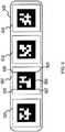
- An example of such a fiduciaryis shown in FIG. 5 .
- the substrate tape 500 of the fiducial objectcan be laid on an investigated object (such a as patient in medical investigations) in an area close enough to the area to be investigated.
- This substratecan be made from a flexible material such as rubber, elastomers, such as silicone, polyurethane and latex, or other material flexible enough to follow the layout of the object.
- the backing that will be towards the patientcan be made of the same material or a different material that is adhesive enough to not allow the fiducial to slide easily across the skin or cloths of the patient.
- the figureshows a fiducial in the form of the letter I.
- Other arrangementsare possible, such as a in a form of a L, T, V, U, or other pattern, the choice of which can depend on the particular area to be investigated.
- One or more rigid piecescan be mounted on this form.
- These rigid piecesare shown in the figure by 501, 502, 503 and 504.
- a patterncan show distinguishable features that allow the machine vision system to get a physical scale of the environment, get a pose estimate, and uniquely identify the type of fiducial, and the place of the piece within the whole fiducial. Some of these features are indicated for the 502 piece. Corners 505, 506, 507, and 508 made by the black squares in the four corners of the 502 piece with the central large square will provide most reliable information to the machine vision analysis to determine scale of the environment and camera pose.
- the middle pattern 509will comprise a distinct binary code that will uniquely identify the corners 505, 506, 507, and 508, as well as the fiducial type, index, and the relative position of the pattern within the whole fiducial.
- FIG. 6A more detailed example of an implementation of the data analysis chain when using passive light sensing devices is shown in FIG. 6 .
- the data coming from the computer vision camerasis analyzed by a computer vision analysis chain.
- an image rectification 601 analysis stepmay be used to correct the position of the pixels in the frame using a pre-measured calibration matrix.
- the calibration matrixis obtained by taking various pictures of known 3D objects or 2D planes positioned at different angles and positions in the field of view. The calibration and rectification methods are commonly known in the field.
- the second computer vision analysis step 602identifies the fiducial object or fiducial marker in the field of view, and uses its apparent shape to determine the position and orientation of the computer vision camera in respect to that fiducial object in the following pose estimator step 603. Since the camera is mechanically registered to the probe, a position and orientation of the probe is determined by simple transformations. In the case in which a fiducial object is not used, various features of the investigated objects or in the environment can be used as reference points.
- the movement of the computer vision system in respect to the investigated objectsmay not be necessary; when fiducials are not used, the algorithms under this step 603 may require the observation of the investigated object by the computer vision camera or cameras from various angles.
- a 3-D modeler (or dense machine vision) step 604may also be used to determine object parameters, such as 3-D models of the contours of the objects being investigated or from the adjacent environment. Building the contour 3-D model reliably using dense machine vision 604 algorithms may also require the observation of the investigated object by the computer vision camera or cameras from various angles. Various features in the field of view are tracked in time across frames taken successively as the camera is moved, and a full 3 dimensional position of the object features is calculated, as in step 604. This process uses computer vision algorithms that create 3-D structure from video.
- Structure from motion algorithmscan be used to build the 3-D contour of the investigated object, environment or patient.
- This contour 3-D modelcan be integrated into the common virtual 3-D model of the setup.
- the registration of the probe within the virtual 3-D modelcan be obtained by analyzing the apparent shape of the fiduciary object, as seen from the computer vision camera on a computer device.
- PnPperspective-n-point problem
- the proper scalecan be determined by using either a stereoscopic computer vision system, a lidar system, a ranging camera, an Inertial Navigation Unit (INU), or a combination of these, each of which registered to the probe or integrated into the probe.
- a stereoscopic computer vision systema lidar system, a ranging camera, an Inertial Navigation Unit (INU), or a combination of these, each of which registered to the probe or integrated into the probe.
- a lidar systema ranging camera
- INUInertial Navigation Unit
- the data coming from the probewhen available, is read-out and adjusted (see step 605) to be used in the 3D Object Structure Reconstruction analysis step 606.
- the information about the probe positionis associated with the probe data coming from the probe data acquisition and analysis step 405 to create spatially registered data.
- steps 606, 607 and 608are similar in function with step 206, 207 and 208 of FIG. 2 , respectively, and their description is appropriate here.
- step 602can be skipped, and the data from step 601 will go directly to step 603.
- This operation modemay be more common in broad area surveillance and mapping applications, where the use of fiducial objects or markers may not always be practical.
- an estimate of the 3D position and orientation of the camerais obtained by tracking features and highlights associated with various objects in the field of view in subsequent image frames. By triangulation, the distance to these highlights can be calculated, and from that, the spatial registration of the sensor in respect to these highlights is determined.
- the 3D model of the whole scenecan be built. However, if there is no reference (or fiducials) in the scene to indicate the absolute scale of the scene, the determined dimensions have relative values.
- IMUinertial measurement unit
- LIDARlaser based range finder
- a lidar system using a laser beamcan be used to get the absolute distance to objects in the environment for selected points.
- the absolute scale of the scenecan be deduced.
- the figureincludes the implementation in which the tracking and spatial registration system uses an external tracking or ranging camera, such as an IMU, a LIDAR, or other system.
- step 609data from an IMU can be used for dead-reckoning or the range data from a LIDAR is used for laser ranging.
- a fiduciary marker or objectcan be mechanically registered to the probe, and a computer vision tracking system or a ranging camera external to the probe can be used to observe the spatial field where the probe will be used.
- the data from the external tracking and ranging cameracan be read-out by a computer unit.
- another tracking systemsuch as an IMU, registered to the probe can be used.
- the data from this tracking systemcan be read-out by the same computing unit that reads the external tracking and ranging camera.
- FIG. 7shows a tracking system that uses electromagnetic waves for ranging.
- An example of electromagnetic wavesis magnetic fields.
- Electromagnetic pulses, including magnetic fields,can be used but in which the active electromagnetic elements are placed inside the instruments and sensor probes, and are used as active elements emitting electromagnetic fields.
- the electromagnetic sensors inside reference objectsare used as passive elements.
- An advantage to this mode of operationis that the amplification electronics required to amplify the signal detected by the passive electromagnetic sensors can be placed very close to the sensors, eliminating the need for long wires between the sensors and amplifiers, reducing noise pick-up.
- electromagnetic sensorsare magnetic sensors, such as coils. Since the magnetic sensors are directional, a set of three magnetic sensors oriented orthogonal to each other will be enough to provide the position and orientation of the probe in 3D in respect to the reference object, if a set of 3 orthogonal active magnetic elements are placed in the probe, and emit magnetic pulses.
- An electromagnetic transmitter 702is mechanically registered to the probe 701 through the mechanical mount 703.
- a computing unit 704which may or may not be mounted to the probe-ranging device assembly, may send and receive data from the probe through connection 705, in the case when such data is available, and from and to the electromagnetic transmitter 702 through connection 706.
- Connections 705 and 706can be wireless, or can be made out of physical cables.
- the computer 704receives and synchronizes the signals and data sent to and coming from the probe 701 and electromagnetic transmitter 702, and performs further processing.
- the investigated subject or environmentis abstractly represented by the rectangular boxes 707 and 708.
- An electromagnetic receiver 709is set on or mounted to an investigated object or instrument in relation to which tracking of the probe 701 needs to be done.
- the signal received by 709is transformed into data that can be transmitted to a computer, such as 704 through cables or wirelessly.
- a "type of signal” that can be used for such a positioning methodis a magnetic signal.
- the transmitteris mechanically registered to the probe.
- unit 709can be used as an electromagnetic emitter and unit 702 can be used as an electromagnetic transmitter.
- the emitter 709will emit electromagnetic fields that will be detected by the electromagnetic sensors 702 mechanically registered to the probes.
- multiple signal receiving elementscan be used for better estimation of the relative position and orientation, or for getting the tracking information for multiple components, objects, instruments of sensors.
- FIG. 8shows another tracking system that uses assemblies of ultrasound transmitters and receivers.
- the setuphas a few elements similar to the embodiments of FIGS. 1 , 3 or 7 .
- an ultrasound transmitter 802is mechanically registered to the probe 801 through a mechanical connection 803.
- Lines 804 and 805are data connections from the probe 801 and transmitter 802, respectively, to a computer 806.
- the ultrasound receiving system 807is an assembly of multiple individual receivers mechanically registered to each other placed on an object 808.
- the coordinate system associated with the probeis 810; the coordinate system associated with the receiver is 811.
- the transmitteremits ultrasound pulses 812 of frequencies preferably above human hearing range, but low enough to insure transmission through air.
- the received signalscan be transformed into data and transferred to the computer 806 wirelessly or using cables.
- the position and orientation of coordinate system 810can be found in respect to coordinate system 811. The calculation can be done on the computer 806 or on a processor integrated with the receiving system 807.
- An application where some aspects of the present invention can significantly make an impactis in the detection of the sentinel lymph nodes using gamma-ray probes.
- Gamma-ray probesare currently used for navigated sentinel lymph node dissection in intra-operative applications. It is of interest to locate and extirpate the lymph nodes (also known as sentinel lymph nodes) that receive the lymph draining from the general area of the cancerous tumor because these are the first places where cancer cells can propagate.
- a solution containing a radioactive tracersuch as Tc-99m
- a collimated gamma-ray detectoris used by a surgeon to determine the position of the sentinel lymph nodes by monitoring the count rates detected by said collimated radiation detector as the surgeon moves the gamma-probe around the relevant body areas.
- a tracking and spatial registration system mechanically registered to a gamma-ray probecan provide the spatial tracking of the gamma-ray probe as the probe is moved around the investigated human body. This will allow the surgeon to get a full three-dimensional distribution of the injected Tc-99m inside the patient and to have that distribution spatially registered to the body of the patient and/or the gamma probe itself and/or other instruments.
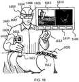
- FIG. 9shows an example of an embodiment that accurately and reliably determines the position of the lymph nodes.
- a patientis represented by the torso shape 900.
- a gamma-ray probeis made out of a probe head 901, handle 902 and tracking system 903 connected to the probe handle by an arm 904.
- the gamma probe assemblycan be made out of an integrated structure, or the tracking system can be mounted on the gamma-probe handle using a mounting mechanism 905 such as a bracketed structure.
- the mechanical structurewill insure high mechanical registration between the gamma-ray probe head 901 and the tracking system 903.
- the gamma-ray probe head 901comprises a gamma-ray detector, such as a semiconductor detector or scintillator, surrounded by a collimator that allows gamma-rays from a limited field of view to enter the detector.
- the field of view of the gamma-ray detectoris represented by the cone 906.
- a distribution of gamma-ray radioactive tracer, such as Tc-99mis represented by the patch 907, which is inside the body of the patient 900.
- Streams of digital data or analog signals coming from the gamma-ray detectorare read out by a read-out and processing unit through a cable 908.
- This cablecan contain wires that also read out the tracking system 903.
- the tracking systemcan be read-out through a separate cable 909.
- the data coming from the tracking unit and from the gamma-ray detectorwill be synchronized inside a read-out processing unit.
- the tracking systemcan be any of the tracking modalities presented above.
- the tracking systemis a machine vision system comprising 3 main elements: (1) a light sensing device 903, such as a video camera, that is appended with high mechanical registration precision to the handle of the gamma probe 902; (2) an active or passive fiducial object, or objects 910, 911, 912, 913 that can be mounted or laid on the patient 900 and that contains active or passive features easily identifiable by the camera 903 (whereas active features can be light emitting elements, passive features can be painted forms); and (3) a data acquisition and processing module, such as a computer that reads the video stream and integrates it with the information obtained from the gamma probe.
- a light sensing device 903such as a video camera, that is appended with high mechanical registration precision to the handle of the gamma probe 902
- an active or passive fiducial object, or objects 910, 911, 912, 913that can be mounted or laid on the patient 900 and that contains active or passive features easily identifiable by the camera 903 (whereas active features can be light emitting elements, passive features
- the field of view for the computer vision camera 903is represented generically by the opening angle 914.
- a spatial registration system similar to 903can be mechanically registered to other surgical instruments to allow tracking their position in space in respect to the same fiducial objects 910, 911, 912, and 913.
- This spatial registration systemwill be read out by the same computer that reads the data and analyses the tracking information provided by 903. This will allow real-time positioning in a common virtual model of all elements of interest, such as all relevant instruments, the gamma-ray probe, the investigated patient, the map of the radioactive hot spots indicating sentinel lymph nodes and potential cancerous tissue, etc.
- a ranging system as described in FIGS. 1 , 7 and 8can be mechanically registered to the gamma-ray probe and other instruments to provide gamma-probe tracking for the lymph node detection application.
- lymph node detection approachbetter sensitivity, better location, lower radiation dose, faster process, and a shorter surgical procedure.
- Another advantage of this approachis that by keeping track of the superposition of the scans and observing the same structures from various angles and positions, it is possible to identify and correct ultrasound specific artifacts, such as reverberations, refractions, ghost images, "comets", etc.
- Another advantage of this approachis that in the intraoperative use of ultrasound to navigate medical instruments, the user, or the operator will have much more confidence in the ultrasound models, since the organs and structures will be spatially much better defined, with much reduced artifacts.
- the surgeonwill be able to follow in real time, in a common virtual model, all elements of interest, such as the medical instruments, the ultrasound scanner, the investigated body, the 3D ultrasound model of the organs, and potentially, other pre-operative models.
- image segmentation algorithmscan be used in the process of merging the 2D ultra-sound images into the 3D ultra-sound model and to delimitate various features in the 3D model, such as organs, tissues, etc.
- Computer expert systemscan also be employed to identify anomalies and other specific features that are clinically relevant.
- the virtual reality modelmay comprise multiple elements, among which are:
- a ranging camera and/or a passive camerawhich is attached to either one of the medical instruments or sensors, or it is positioned to observe the environment comprising the patient, medical instruments, and potentially, the local clinician.
- This approachis exemplified by using an ultrasound imaging application.
- FIGS. 10A-10Bshow examples of two ultrasound probe housings that comprises passive machine vision cameras and IMUs mechanically registered to the probe for probe tracking.
- FIG. 10Ashows an ultrasound probe housing assembly with a detachable camera housing shell.
- An ultrasound imaging probe housing shell 1001is in contact with the investigated patient 1002 through the ultrasound probe head 1003 which comprises an ultrasound transducer.
- the ultrasound transducercan comprise a mechanically scanned transducer, a phased array of transducers, or a combination.
- Mechanically registered to the probeis a camera housing shell 1004 comprising a camera whose lenses 1005 are oriented in the general direction of the patient.
- the communication with the ultrasound probe inside housing 1001is done through a cable 1006, which can be an universal serial bus (USB) cable or other type of cable that goes to a read-out device.
- USBuniversal serial bus
- This read-out devicecan be a computing unit, such as a laptop, computer, tablet, or a smart phone, or a routing device when the housing 1001 of the probe comprises electronics able to create beam-forming signals to be sent to the transducers and to read-out and condition the signals received from the transducers. Otherwise, the read-out device will comprise beam forming and signal conditioning electronics, as well as a computing unit.
- the data transport between the computing device and the cameracan be done wirelessly or through a cable 1007, which can be an USB, FIREWIRE ® , or other cable that ultimately sends the computer vision data to a computing unit that also receives data from the ultrasound probe.
- a cable 1007can be an USB, FIREWIRE ® , or other cable that ultimately sends the computer vision data to a computing unit that also receives data from the ultrasound probe.
- An Inertial Measuring Unit (IMU) 1008may be integrated into the probe housing shell 1001, into the camera housing shell 1004, or in any other way mechanically registered to the ultrasound probe.
- the IMUis shown inside the body of the ultrasound probe housing shell.
- the IMUcould be used by itself, or in conjunction with the camera, or in conjunction with ultrasound speckle de-correlation analysis to determine the position and orientation of the ultrasound probe at each moment in time.
- Kalman filterscan be used to combine the positioning information form the computer vision subsystem and the IMU.
- Fiduciary elementscan be placed on the patient or on stable objects adjacent to the patient to give a reference frame for the virtual reality model and to provide the proper scale for the whole environment when using the computer vision system for registering the ultrasound probe into the 3-D model.
- the fiduciary elementcan be made of a patterned layer made of various colors or shades, can comprise reflective objects, or active lighting elements, such as light emitting diodes (LEDs). Likewise, the fiduciary element can be rigid, flexible, or piece-wise rigid. Additionally, a miniature light projector, light source, LED or laser can be integrated into the system, such as into the body of the machine vision camera subsystem 104, to cast a light onto the field of view of the camera for better visualization.
- LEDslight emitting diodes
- the fiduciary objectmay not be used, and in order to get calibration and scale information, the camera video stream is combined with the IMU data.
- the computer vision algorithmscan analyze the apparent position of these highlights to determine the position and orientation of the camera, and by simple transformations, of the probe.
- FIG. 10Bshows an embodiment of an ultrasound transducer with a machine vision and tracking subsystems integrated into the body of the housing for probe.
- the ultrasound imaging probe housing 1011is in contact with the investigated patient 1012 through the ultrasound probe head.
- the body of the ultrasound transducer subsystem inside the ultrasound probeis represented schematically by dashed box 1013.
- the ultrasound transducer subsystemcan comprise a mechanically scanned transducer, a phased array of transducers, or a combination of these.
- a board 1014accommodates all these electronics. This board can be connected to a cable 1015 that makes the connection to a computing unit or visualization device. Alternatively, the on-board electronics can communicate wirelessly with other computing and visualization units.
- An IMUis abstractly shown connected to the on board electronics 1014 as the dashed box 1016.
- a board 1017accommodates the camera. This board can be electrically in contact with the board 1014.
- the body 1018 of the camera and lensesis within housing 1011.
- a visor 1019 on the ultrasound probe bodyallows light to penetrate into the lenses of the camera.
- a button 1020 on the probe housingcan be used for the user to interact with the functionalities of the system. For example, it can be used to start and stop the system, change acquisition modes, etc.
- ranging systemscan be used to determine the contour of the patient and to track and spatially register the ultrasound probe in respect to the patient and other instruments.
- FIGS. 11A-11Cshow examples of ultrasound imaging probes with tracking capability using ranging cameras mechanically registered to the ultrasound probe.
- a ranging camera as described in FIG. 1is used.
- the drawings of the figuresshow an ultrasound probe housing 1101 in contact with an investigated patient 1102.
- FIG. 11Ashows a lateral sectional view of the probe housing.
- FIG. 11Bshows a front view of an embodiment with one ranging camera.
- FIG. 11Cshows a front view of an embodiment with two cameras.
- the ultrasound transducer subsystem 1103is inside the body of the probe.
- the ultrasound transducer subsystem 1103is connected to electronics comprising signal generation, signal conditioning, data processing and read-out components, also placed inside the probe housing shell.
- Dashed box 1104is an abstract representation of such electronics. The data transfer between 1104 and a computing and visualization units can take place wirelessly or through a cable 1105.
- the ranging camerais placed in camera housing shell 1106, which can be integrated into the ultrasound probe housing shell 1101, or can be mounted on it.
- the housing shell comprising the ranging camera and tracking elementsslides into a shoe 1107 on the ultrasound probe housing shell 1101 where it gets fixed with high mechanical registration.
- a board 1108accommodates the ranging and tracking components.
- a visor 1012 on the probe housingallows ranging signals (such as IR light) to penetrate into the lenses of the ranging camera 1110.
- a generic field of view for the ranging sensoris represented by the angle opening 1113.
- the tracking subsystem board 1108can be connected directly to read-out electronics or a computing unit through a cable 1114 or wirelessly. Alternatively, the board 1108 can be connected to the electronics inside the ultrasound probe housing shell 1101 through a connector assembly 1115. Whereas the cable 1116 makes the connection inside the tracking subsystem housing shell between the board 1108 and the connector 1115, the cable 1117 makes the connection inside the ultrasound probe housing shell 1101 between the connector 1115 and the board 1104 or between the connector 1115 and the read-out cable 1105, directly.
- the electrical connection inside the connection system 1115can be made when the tracking subsystem housing shell 1106 is slid into the shoe 1107.
- a button 1118 on the probe housing shellcan be used for the user to interact with the functionalities of the system. For example, it can be used to start and stop the system, change acquisition modes, etc.
- FIG. 11Bshows a front view of the whole assembly sselling a single ranging sensor.
- one or more light sources 1109are part of the time of flight camera, whereas the light sensing component of the time of flight camera is behind the window 1112.
- the level arm between the light source 1109 and the light sensorwill be increased so that appropriate ranging performance is obtained for the range of distances of interest.
- FIG. 11Cshows a front view of the whole assembly sselling two light sensors behind windows 1112 and 1119.
- one or more light sources 1109can be combined with two time of flight light sensiors behind the windows 1112 and 1119.
- a structured light source 1109can be combined with two light sensors behind the windows 1112 and 1119 on either side of the structured light source to create a stereoscopic structured light camera. This arrangement will insure overlap in the field of view of the structured light source with the field of view of at least one light sensor.
- the ranging cameracan use most preferably IR light, so that the light source 1109 is a IR light source, and light sensor is optimized to detect IR light. However, light or any color could be used.
- a ranging assemblycan be made of one or more light sources 1109 and a ranging sensor behind window 1112, and the sensor behind window 1119 can be a non-ranging light sensor, such as a RGB (red green blue) or black-and-white (B/W) CMOS or CCD.
- a light source 1109can be used mainly for scene illumination, with the sensors behind windows 1112 and 1119 forming a stereoscopic camera. In this case, stereoscopic machine vision algorithms can be used on the computing unit to analyze the data from the two sensors to create a dense, 3-D model of the contour of objects, and for spatial registration of the ultrasound probe in respect to the investigated patient.
- the ranging and probe tracking embodimentscan also be used in conjunction with other probes, such as gamma-probes for lymph node detection as described above and in FIG. 9 .
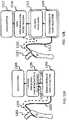
- FIG. 12shows various ways in which an ultrasound probe with integrated tracking capabilities as exemplified above can be coupled to read-out, data processing and visualization units.
- FIG. 12Ashows a read-out which more closely integrates the streams from the tracking subsystem and ultrasound probe.
- the ultrasound probe assembly 1201is shown with two cables, one 1202 primarily for ultrasound control and data read-out, and another one 1203 primarily for tracking subsystem control and data read-out. Two cables shown in the figure, but a single cable can also be used to carry all information.
- the two connections 1202 and 1203connect to an electronics module 1204 comprising components for beam-forming, signal processing and data collection. Inside module 1204 data from the tracking subsystem and ultrasound probe can be time synchronized and associated with each other.
- the data connection 1206transmits primarily tracking subsystem data between the data conditioning unit 1204 and the computing unit 1205.
- data connection 1207transmits primarily ultrasound probe scan data between the data conditioning unit 1204 and the computing unit 1205.
- Data connections 1206 and 1207can use the same cable or connections, or separate connections. Units 1204 and 1205 can be physically separate, or integrated into a single device.
- all or part of the electronics of 1204can be integrated into the ultrasound probe housing.
- the connections 1202 and 1203can link directly to the computing unit 1205.
- Examples of such a computing unitare: a computer, laptop, tablet, smart phone, or other custom processing unit.
- the computing unititself can be integrated into the housing of the ultrasound probe assembly 1201.
- algorithms and methodscan be used to prepare ultrasound data for visualization, to register the ultrasound probe in respect to the patient by analyzing the probe tracking information, to build 3-D models of the patient, to allow users to control and manipulate ultrasound and tracking data, to store investigation data, to retrieve previously stored data, to provide connections with other computing units, internet or local network, servers, etc.
- FIGS. 13 and 14shows examples of such methods that can be implemented inside the computing unit.
- a visualization device 1206such as a monitor, touch screen, projector, head mounted displays, goggles or augmented reality glasses can be used to visualize and interface with the data.
- the operator of the probecan interface with the system though a mouse/keyboard, touch screen, joystick of other non-contact devices, such as structured light or time of flight ranging systems that interpret the hand and finger movements of the operator.
- FIG. 12Bshows a read-out which does not closely integrate the streams from the tracking subsystem and ultrasound probe. This implementation is more suitable when the probe tracking capability and associated methods are implemented to existing ultrasound machines. Such implementation would allow existing ultrasound systems to be fitted with new ultrasound probes that have tracking capability.
- the ultrasound probe assembly 1211is shown with two cables, one 1212 primarily for ultrasound control and data read-out, and another one 1213 primarily for tracking subsystem control and data read-out.
- the ultrasound probe assembly 1211is shown with two cables, one 1212 primarily for ultrasound control and data read-out, and another one 1213 primarily for tracking subsystem control and data read-out.
- the electronics module 1214 for beam-forming, signal processing and data collection and the computing unit 1215 for further processing and visualizationare integrated into a common physical body.
- ultrasound scan outputsuch as a data or video output for the visualization of ultrasound scan and controls on external monitors.
- This outputcan be read-out by a second computing unit 1216 which also connects to the tracking subsystem through connection 1213.
- Methods for data synchronization, data processing, probe registration, 3-D model formation, data storage and retrieval, user interface, communication with other servers or computers, and connection to networkscan be implemented inside unit 1216.
- a visualization device 1217similar to 1206 can be used to visualize and interface with the data.
- ultrasound investigationssuch as remote-guided ultrasound investigations, computer guided ultrasound investigations, ultrasound stereotaxy, freehand spatial compounding, tissue characterization, tissue elastometric property characterization, and enhanced freehand 3-D ultrasound. Many of these methods are made available by probe tracking techniques as introduced here, or other tracking techniques.
- FIG. 13shows an example of how such methods can be implemented in a computing device.
- the processes supporting the introduced methodscan be separated in three main blocks: tracking and volumetric modeling, ultrasound processing, and visualization and interface.
- modules 1301 to 1309are part of the tracking and volumetric modeling block
- modules 1312 to 1317are part of the ultrasound processing block
- 1310, 1311, 1318, 1319, 1320are part of the visualization and interface block.
- the data from the ranging system and/or machine vision system 1301can be combined with the data from a tracker 1302, such as an IMU inside the 1303 processing module inside the computing unit, to create ultrasound probe tracking information.
- the combined datacan also be used to build the 3-D outline of the patient inside module 1304.
- Other data stored on a local storage device or from the network 1305can be loaded to support functionalities, such as expert guidance, remote guidance and ultrasound stereotaxy. This data is loaded into a gateway module 1306.
- the probe tracking information from 1303, the patient contour information from 1304 and other stored information from 1306can be merged to build a virtual reality (VR) model inside module 1307.
- This modelcan comprise the contour of the patient, models of the ultrasound probe in respect to the patient, 3-D or sectional organ models, current and previously stored ultrasound and other imaging models, other medical instruments, graphical user interface components, links to other data, and other linear, areal and volumetric components and measures.
- the VR modelcan be sent over the network, or locally saved in its whole or parts of it inside 1308 module.
- the data sent to module 1308can be associated with other data, such as the ultrasound data of 1314.
- Another analysis block in the figureincludes ultrasound analysis processes.
- the ultrasound data stream coming from the ultrasound probe read-out 1312is synchronized and associated with the probe tracking data stream so that the probe tracking information is appended to the ultrasound data bunches inside module 1313.
- the ensuing time- and position-registered ultrasound streamwhich will be called a "spatially registered scan,” can be sent over the network or saved locally on a storage device 1314.
- the VR modelin its entirety or parts of it can be appended to the ultrasound data saved on the local storage device or sent over the network to another location.
- the ultrasound datacan be analyzed to create 2-D scans, such as B-scans, elastography map, Doppler flow or other tissue characterization maps inside module 1316.
- the spatially registered ultrasound scanscan be analyzed using spatial compounding methods to not only filter out ultrasound speckle and artifacts, but also to extract more accurate information about types of tissues inside module 1317. This can be done by analyzing multiple spatially registered scans that cover the same area from different ultrasound transducer positions and angles. In the present context, this spatial compounding analysis can be referred to as a limited scope 3-D freehand ultrasound.
- the 2-D scans delivered by 1316can then be visualized inside the visualization and interface module 1318.
- the spatially compounded model or tissue type model delivered by 1317can be visualized by module 1319.
- the spatially compounded model to be visualizedwill be updated repeatedly to include the data from the latest spatially registered scans.
- the usercan observe on a visualization device the section of the compounded model or tissue type model that corresponds to the section being scanned at that moment by the ultrasound probe. In this way, the user can easily navigate the spatially compounded model or tissue type model by moving the ultrasound probe on the patient. Controls can be provided to the user to adjust visualization and processing settings for the tissue characterization maps.
- the maps visualized by modules 1318 and 1319can also be merged into a common visualization module.
- a full 3-D modelcan be created. This can be referred to as "freehand 3-D ultrasound imaging.”
- This processis indicated in module 1315.
- the datacan come from a local storage device, from the network, or directly from a memory. The process can take place off-line, but if computing resources are available, it can also take place in real-time.
- the output modelcan be saved on a local storage device, sent over the network, or sent to a visualization module 1320 optimized to visualize 3-D models, including tissue type, elastometric property, flow, or to the more generic VR visualization module 1310.
- FIG. 14gives an example of how some of the above methods can be integrated into a telemedicine and operator guidance system.
- the local system 1401is the system setup at the place where the patient is treated or evaluated by the "local" clinician.
- the remote system 1402is the system setup at the site of the "expert" remote clinician.
- the exchange of datais done through a communication network 1403. This can be, for example, an Internet network, a local computer network, or a wireless network.
- the Computer Vision System 1404may provide 3-D models, such as patient 3-D contour, as well as probe tracking information.
- the tracking information from 1404, if available,is combined with the tracking information delivered by the inertial measurement unit system 1405.
- a 3-D virtual modeler system 1406merges the information from 1404 and 1405 into a combined 3-D model.
- This modelis send over the communication network 1403 to the remote system 1402, where it is combined with tracking information provided by the remote tracking system 1407.
- the core purpose of the remote tracking system 1407is to allow the remote clinician to communicate to the local clinician his or her choice in what regards the manipulation of a medical device, such as an ultrasound imaging probe.
- the data streamed out of 1407will comprise the position and orientation of the probe, as elected by the remote clinician.
- the remote usershould have an intuitive way to do it.
- a machine vision system combined with an IMU tracking system similar to the setup at the "local" sitewill most probably be the most intuitive way.
- the "remote" userwill just have to move a mock-up medical instrument at the remote site in a similar fashion as the local clinician.
- a combined 3-D virtual reality modeler and movement guidance system 1408will include the position of the medical instrument proposed by the remote user into a common 3-D model.
- the position of the medical instrument proposed by the remote user delivered by 1407will be sent over the network to the local system to be combined with the 3-D virtual model within the a combined 3-D virtual reality modeler and movement guidance system 1409, which is basically a mirror of the remote system 1408.
- the purpose of 1408is to create feed-back to the remote user in what regards her/his proposed position of the medical instrument in respect to the 3-D model
- the purpose of 1409is to create information for the local operator she or he can use for guidance in how to manipulate the medical instrument.
- the stream of data coming from the medical instrument 1410will be visualized locally by the local operator using a visualization system 1411.
- the combined 3-D model coming from 1409will be visualized as well, preferably on the same device 1411.
- the remote userwill monitor the visualization system 1412 to inspect the data taken by the medical instrument 1410, and to get feed-back on her or his manipulation of the probe mock-up that is part of the remote tracking system 1407.
- the visualization systems 1411 and 1412can be screens, or augmented reality systems worn by operators or users.
- the remote tracking systemcan utilize a similar tracking system as the local tracking system, or it can be implemented in several other ways. Examples are: a joystick, a computer mouse, a keyboard, a ranging device, or other human interfaces.
- the visualization area 1501may comprise one or more windows and panels. In a more general implementation, the visualization area will comprise a panel 1502 containing buttons and links to settings and controls for the ultrasound system, computer vision system, IMU, visualization, data processing modules, etc.
- the ultrasound image 1503may represent a regular B-scan, or a more advanced imaging output, such as a tissue type weighted image, fluid flow, tissue movement, tissue type, tissue elastometric properties, or a combination of any of these.
- the window 1504shows a 3-D representation of the 3-D virtual model of the setup. Other windows can show footage of the computer vision or ranging camera in window 1505, and other data in window 1506, such as video image from the remote site, or processed ultrasound data, such as:
- the window 1504 comprising the 3-D model of the patientcan also comprise any of the elements described for window 1506, as well as 2-D ultrasound scans.
- the purpose of this windowcan be to guide the local clinician on the best position and orientation of the probe in respect the patient 1507.
- the best position and orientation of the probeis suggested either by the local analysis results, as indicated by a computer system, or as recommended by a remote user.
- the 3-D model ultrasound probe 1508is shown positioned in respect to the 3-D model of the patient 1507, as obtained by the tracking system.
- the recommended position of the probeis represented by the graphical guiding element 1509.
- the recommendationcan be given by an automatic computer system, or by a remote user, as described in FIG. 3 .
- other visual and numeric elementscan be shown, such as curved 1510 and directional arrows 1511, representing the rotation and translation the probe has to make to overlap the position of the virtual probe 1509.
- geometrical appearance of these elementscan give fast feed-back to the local operator on how large the movement of the probe must be until it overlaps the virtual probe 1509.
- numerical valuessuch as amplitude of angles (in degrees) and measures of distances (in millimeters), each, in all three directions, can be overlapped to give the local operator information about movement of the probe must be until it overlaps the virtual probe 1509.
- a color codecan be used to represent each of the three spatial directions for translations and each of the three angles for rotations, whether shown as numbers or geometric elements, such as the arrows 1510 and 1511.
- an augmented reality systemcan be employed, so that the local operator can observe an overlay of relevant elements over a direct view of the clinical set-up.
- elementsthat can be overlaid are: models of medical instruments, such as the virtual probe 1509; numerical and graphical indicators, such as directional arrows 1510 and 1511; 3-D anatomical models; ultrasound images and models, and others.
- One disadvantage of tele-guided ultrasound functionalityis that a highly trained expert is still required to be available for the investigation.
- An alternative to thatis to have a local computer guidance system that has preloaded procedures for a large array of clinical investigations.
- the patient contour as measured by the ranging or light sensing systemcan be matched to the outline of a generic human model. This will allow the computer guidance system to give precise instructions about the positioning and movement of the ultrasound probe in respect to the real patient model.
- Ultrasound anatomical landmarks observed in real-timecan be matched in 3-D to landmarks in the 3-D models for a much more precise registration that will correct for organ movements and displacements due to variations in body habitus and position.
- An ultrasound image interpretationcan be given by the local user, expert system, or later by a radiologist.
- a "stereotactic ultrasound" instrument as described hereincan allow the user to label features of interest in 3-D, and register them with respect to the patient model so that follow-up investigations can easily use those coordinates to re-evaluate medical conditions.
- the usercan be given software tools to mark features in the 2-D ultrasound scan. Since the ultrasound probe position will be spatially registered to the 3-D model of the patient contour, the marked structure will be registered within the 3-D patient model. Moreover, the positioning of the ultrasound probe with respect to the body can be retained so that it can be reproduced by an operator at a later moment.
- ultrasound anatomical landmarks observed in real-timecan be matched in 3-D to ultrasound landmarks previously stored during previous examinations, or to other 3-D models, for a much more precise registration that will correct for organ movements and displacements.
- Tools for volume segmentation and measurementcan be used to quantitatively evaluate various conditions and to track changes in time.
- An advantage of the ultrasound systemis that it can be used very efficiently as a "freehand" 3-D ultrasound system.
- a "freehand ultrasound”uses a regular 2-D ultrasound probe as the operator moves it across the body of the patient. Combining successive 2-D ultrasound images, a 3-D model of the whole investigated volume is formed. Since a whole 3-D model will be created by keeping track of all 2-D scans, the final result of the investigation will be practically independent on the skill of the operator to take relevant ultrasound cross-sections, and to notice relevant features.
- a tracking systemcan make freehand 3-D imaging functionality possible in an inexpensive, operationally efficient way.
- Various 3-D ultrasound modelssuch a tissue type weighted image, fluid flow, tissue movement, tissue elastometry properties can be obtained by using the freehand ultrasound capability of the system.
- a real-time 3-D modeling of the patient layoutwill help the freehand ultrasound imaging process by providing information about changes in the patient position and skin layout. These changes can occur, for example, because of forces applied on the patient skin, such as by the ultrasound probe, voluntary of involuntary changes in the patient position, and because of patient breathing. This capability will help prediction of organ movement, improving the quality of the 3-D ultrasound modeling.
- Tracking methods and systemsthat use at least a camera or ranging device to track the relative position of instruments, sensor probes, objects or parts of a user in respect to each other, or in respect to the at least one camera or ranging device are proposed.
- the at least one camera or ranging devicecan be positioned in such a way as to observe the general area where instruments, sensor probes or objects of interest or being acted upon by the user are positioned.
- the at least one camera or ranging devicecan be positioned on a mount or on an object adjacent to the general work area, or can be carried by a human or robotic user.
- Examples of the at least one camera or ranging devicesare: visual color camera, visual B/W camera, IR camera, plenoptic camera, time-of-flight camera, stereoscopic camera, structured light camera, stereoscopic structured light camera, ultrasound trackers, or electromagnetic trackers, such as magnetic trackers or radio-frequency trackers.
- a computing unitcan be operatively coupled with a memory and the at least one camera or ranging device, the memory having instructions for execution by the at least one processor configured to determine a spatial position and orientation of the instruments, sensor probes, objects or parts of a user in respect to each other, or in respect to the camera.
- fiducial markers or objectscan be mounted on instruments, sensor probes or objects of interest to better determine their position and orientation. Examples of fiducial markers are reflective objects, objects with distinct shapes, binary black and white or colored coded tags with distinct codes.
- more than one fiducial elementcan be mounted or attached to each of these.
- a cube like elementcan comprise tags on each of its surfaces, so that at least one tag can be seen from any angle by the at least one camera or ranging device.
- the at least one camera or ranging deviceis an ultrasound tracker
- ultrasound detectorsmechanically registered to the objects, instruments or sensor probes will be used.
- electromagnetic sensorsmechanically registered to the objects, instruments or sensor probes will be used.
- Tracking the location and orientation of instruments, sensor probes and investigated objects in respect to the at least one camera or ranging systemis done using the methods described earlier in this invention.
- of relevanceis mainly the relative location and orientation between instruments, sensor probes and investigated objects. This is achieved by transformations taking into account the position and orientation of each element in respect to the at least one camera or ranging system.
- a computing unitcan be operatively coupled with a memory and the at least one camera or ranging device, the memory having instructions for execution by the at least one processor configured to create a 3-D model of the setup, including a contour of the objects of interest, instruments, or sensor probes.
- At least one processorcan be operatively coupled with a memory and the at least one camera or ranging device, the memory having instructions for execution by the at least one processor configured to observe and analyze movements of interactivity elements, such as parts of user's body or other objects, interpreting those movements to activate a process inside the at least one processor.
- interactivity elementscan be: fingers, arms, instruments, pens, sticks, styluses.
- a display operationally coupled to the at least one processorwill show the position of these interactivity elements in respect to a graphical user interface element, virtually positioned in the same general space as the interactivity elements.
- the userwill be given regular computer interactivity tools such as: click, scroll, navigate files, models or images, zoom-in, zoom-out, type, etc.
- the displaycan be a computer monitor, an augmented reality system, and a head-mounted display.
- the at least one camera or ranging systemcan be part of a head-mounted tracking and visualization (HMTV) system.
- HMTVhead-mounted tracking and visualization
- This HMTV systemcan comprise not only tracking and ranging components, but also a display that allows the user to see images of interest, VR models, graphical interfaces, an augmented reality model, or other elements of interest.
- the usercan use objects, or parts of his or her body to interact with the computer by moving them in the field of view of the at least one camera or ranging system.
- the HMTVcan also comprise an IMU.
- the usercould employ head gestures to execute a process on the at least one processor.
- FIG. 16shows an example of an implementation where the at least one camera or ranging device is mounted on a HMTV system.
- a user 1600such as a physician, investigates a object of interest 1601, such as a patient, using a sensor probe 1602, such as an ultrasound probe.
- the userwear a head mounted tracking and visualization system (HMTV) 1603, which comprises a camera system made out of two light sensing devices 1604 and 1605 and a light emitter 1606, which can be part of a structured light camera, a time of flight camera, a LIDAR sensing camera, or a flash LIDAR camera. More cameras could be used.
- HMTVhead mounted tracking and visualization system
- This camera systemcan comprise a time of flight camera and a non-time-of-flight camera, a stereoscopic structured light system, a single camera structured light system and a visual camera, or any other combination.
- the display 1607is part of the HMTV system. Alternativally, or additionally, an external display can be used.
- the display 1607can be a semitransparent display, can be an opaque display, or can be designed to only cover a part of the user's visual field of view. A representation of an image that could be shown by the display 1607 is shown inside the rectangle 1608.
- the sensor probe 1602carries a fiducial object 1609, mechanically registered to it, in the shape of a cube, on the surface of which distinct binary fiduciary tags are shown. In this figure, only two tags are visible: 1610 and 1611.
- This fiducial objectcan be part of the same housing shell as the sensor probe, can be part of a housing shell that mounts to the sensor probe housing shell in a similar fashion as camera housing shell 1004 or 1106, or can be mounted with a bracket on the sensor probe housing shell.
- both a fiducial object and a cameracan be mechanically registered to the sensor probe or instrument.
- camera housing shells, such as 1004 or 1106)can be interchangeable with the fiducial object 1609.
- Another fiducial object 1612 in the form of a piece-wise rigid fiducial with distinct binary codingcan be laid down or fixed to the investigated object 1601.
- the user 1600can use his or her fingers 1613 as interactivity elements to interact with the computer (not shown).
- the computercould be carried by the user.
- the computercan be partially contained by the HMTV housing.
- the computercan be placed inside the sensor probe housing 1602.
- Buttons B1, B2, B3, B4, B5showed by the display represent generic graphical user interface a user can virtually touch with interactivity elements 1613 to execute a process on the computer.
- button B4is labeled by reference numeral 1614.
- the display 1607also shows a 3-D virtual model 1615 or stereoscopic view of the setup, as it could be created by the camera system on the HMTV 1603, by itself, or in combination with other cameras or ranging systems mechanically registered to instruments or sensor probes, or mounted on other external objects.
- the purpose of this windowcan be also for computer and remote guidance as explained above.
- Window 1616shows a scan delivered by the imaging sensor probe, in this case, this is an ultrasound scan.
- another tracking systemsuch as an IMU, can be mechanically registered to the HMTV or to the instrument and sensor probes for improved tracking performance, and for supplementary user interactivity with the computer.
- this implementationcan allow for remote and computer guidance, ultrasound stereotaxy, freehand spatial compounding, freehand tissue elastometry, freehand 3-D imaging, tissue characterization, as well as other applications, such as needle guidance using ultrasound, ultrasound assisted surgery, etc.
- this implementationwill allow the surgeon to visualize directly on the display the 3-D distribution of the radioactive tracer with respect to the body outline.
- Stereotaxy, computer and remote guidance usescan also be found when the instrument or sensor probe is any of the following: hand-held imaging device, surgical instruments, laparoscopic instruments, etc.
- Spatial registration systems attached to surveying sensorscan be used to automatically perform environmental surveys.
- the spatial registration systemwill conveniently provide the position and orientation of the system in relationship to the investigated objects or to the adjacent environmental objects, keeping an automatic log of the surveyed locations. This capability will also allow for an automatic mapping of the investigated features.
- any of the following sensorscan be used: a radiation dosimeter, a spectroscopic detector, a radiation imaging system, a spectroscopic imaging system.
- this capabilitycan be used to map a chemical field using chemical or biological sensors.
- FIGS. 17A-17Cillustrate a probe, such as a dosimeter, radiation detector or chemical sensor, attached to a smart phone.
- a portable computer or a smart phone 1701can be used for computer vision processing, for data visualization using its built-in screen 1702 and for video image capture using the built-in camera 1706.
- an extra built-in video camera 1707can be used for stereoscopic implementations.
- a sensor probe 1703is clipped on to the smart phone device 1701 with good mechanical registration through arm 1705 and connector body 1704.
- probe sensors 1703can be radiation detection devices, radiation dosimeters, radiation imagers, spectroscopic radiation imagers, chemical sensors, biochemical sensors, infra-red sensors, etc.
- a software program on the smart phone or the equivalent portable computercan be used to acquire the data from the built-in video cameras and from the sensor probe. Furthermore, the program can contain the necessary computer vision algorithms to provide spatial registration and tracking of the sensors in respect to the investigated environment and objects. Having this, a field map of the investigated environment can be obtained. For example, if a radiation dosimeter is used as a sensor probe, a map of the radiation dose field is obtained. The map can be ID, 2D or even 3D, as demanded by the application. Where the local processing power allows it, the processing can be done completely on board. Where local processing power is not sufficient to accommodate all software needs, raw or partially analyzed data can be sent wirelessly or through wires to another external processing unit.
- FIGS. 18A-18Cshow a hand-held probe with an integrated spatial registration system.
- a dedicated hand-held devicecontains the spatial self-registration system body 1801, a body 1802 that comprises the sensor probe, data acquisition and processing unit (computer), and a handle 1804 that may comprise battery, voltage supply, or other sensors.
- a screen 1803may be integrated for visualization and user interfacing.
- the spatial self-registration systemmay comprise one or more cameras 1805 and 1806, a laser beam source 1807, a sensor 1808 to detect reflected laser light.
- the laser beam assembly made of 1807 and 1808can be used for laser ranging (lidar), for time of flight ranging, or for structured light ranging in order to obtain supplementary range information about the scene.
- the data acquisition and analysis softwarecan be implemented on board of the hand held device on the processing unit. Likewise, the algorithms for spatial self-registration can be implemented on board. Alternatively, the data can be sent wirelessly or through wires to other external processing units. As explained above, such system may also include an INU and a GPS sensor.
- FIG. 19illustrates a representation of the way the device shown in FIG. 7 can be used in practice.
- the user 1901will hold the survey system 1902, such as a chemical sensor or a radiation dosimeter, that has self-registration capability (similarly to the device shown in FIG. 18 ) to scan the field but also to acquire information about the relative position of the sensor in the environment.
- the system 1902may contain a lidar ranging system that points a laser beam 1903 to the adjacent objects.
- the video camera(s) integrated into the system 1902may have a field of view represented by the lines 1904.
- a computer vision algorithmcan be used to identify the laser spot in the visual picture allowing a match of the range information from the lidar with the features seen by the computer vision camera. This will allow absolute scaling of the 3D model delivered by the computer vision system.
Landscapes
- Health & Medical Sciences (AREA)
- Life Sciences & Earth Sciences (AREA)
- Engineering & Computer Science (AREA)
- Physics & Mathematics (AREA)
- Medical Informatics (AREA)
- Surgery (AREA)
- Veterinary Medicine (AREA)
- Biomedical Technology (AREA)
- Heart & Thoracic Surgery (AREA)
- Animal Behavior & Ethology (AREA)
- General Health & Medical Sciences (AREA)
- Public Health (AREA)
- Molecular Biology (AREA)
- Pathology (AREA)
- Biophysics (AREA)
- Nuclear Medicine, Radiotherapy & Molecular Imaging (AREA)
- Radiology & Medical Imaging (AREA)
- Radar, Positioning & Navigation (AREA)
- Remote Sensing (AREA)
- Computer Networks & Wireless Communication (AREA)
- General Physics & Mathematics (AREA)
- Electromagnetism (AREA)
- Computer Vision & Pattern Recognition (AREA)
- Human Computer Interaction (AREA)
- Acoustics & Sound (AREA)
- High Energy & Nuclear Physics (AREA)
- Optics & Photonics (AREA)
- Oral & Maxillofacial Surgery (AREA)
- Robotics (AREA)
- Dermatology (AREA)
- Anesthesiology (AREA)
- Hematology (AREA)
- Ultra Sonic Daignosis Equipment (AREA)
- Nuclear Medicine (AREA)
- Length Measuring Devices By Optical Means (AREA)
Description
- Generally, this application relates to position and orientation determination devices for surgery and other contexts. Specifically, this application relates to computer vision and ranging tracking systems for medical instruments and sensor probes.
- Currently, hand-held sensor systems are being used for several applications, ranging from environmental surveys of chemical, biological and radioactive environments, to medical investigations for diagnostics, disease characterization and intraoperative guiding and imaging. Because they are hand-held, they can be immediately positioned and oriented with almost all of the outstanding flexibility and adaptability of a human operator's hands.
- In some instances, a user may wish to know exactly how and where a sensor system is pointed. Yet, the flexibility and adaptability of hand-held sensors also can make them difficult to track. Prior art approaches at spatial registration of sensors and instruments are bulky, cumbersome, expensive, or not practical. There are several examples in which sensor systems were outfitted with a Global Positioning System (GPS) antenna, Inertial Navigation Unit (INU), magnetic sensors, or optical markers.
- Unfortunately, GPS only provides coarse, limited spatial resolution and does not work reliably when satellite GPS signals are weak. INU systems drift over time. Magnetic sensors are generally useful for tracking objects within a small volume of space, around 0.1 to 1 square meters (m3). In a controlled laboratory environment, magnetic sensors can provide location resolution of about 1 millimeter (mm) inside volumes around 0.2 m3 and orientation precision to within a degree. However, when used in realistic applications where metallic objects are present, or when other magnetic fields are generated by adjacent electronic equipment, the position resolution decreases to several centimeters within a 0.2 m3 volume. This position resolution is too coarse for many applications, including medical diagnostic and medical interventions where multiple electronic instruments and metallic objects are used. Optical markers attached to probes require a direct and continuous line of sight to an external Coordinate Measuring Machine (CMM) camera system. Generally, CMM camera systems are bulky, expensive and impractical for most applications in where hand-held systems are used or desirable.
U.S. Patent Application No. 2009/0259123 A1 proposes a CMM-type system for tracking hand-held sensors and instruments for intraoperative navigated sentinel lymph node dissection. The system proposed therein uses external infra-red cameras to track coded infrared reflective markers attached to the hand-held probes or hand-held instruments. One drawback of this approach is that a continuous line of sight needs to exist between external cameras placed above a surgery table and all of the markers placed on probes, instruments, and samples. The hands, arms, and heads of the surgeons may easily break the line of sight during surgery procedures.US2004054248 discloses a radioactive emission probe equipped with a position tracking system useful for calculating the position of a concentrated radiopharmaceutical in the body in positional context of imaged portions of the body, which information can be used, for example, for performing an efficient minimally invasive surgical procedure.U.S. Patent Application No. 2012/0253200 A1 uses an augmentation device in the form of a bracketed structure to be appended to an existing imaging probe to project a pattern of structured light onto the skin or an organ of a patient to facilitate stereo object recognition.- There is a need for better, less expensive, and more accurate and precise tracking of hand held sensors and medical instruments.
- A spatial registration apparatus according to
claim 1 is disclosed. FIG. 1 illustrates tracking and spatial registration of a medical instrument or sensor probe using a ranging device mechanically registered to a probe.FIG. 2 is a flowchart of data processing steps using a generic ranging and tracking system mechanically registered to the probe.FIG. 3 . illustrates tracking and spatial registration of probes with respect to an investigated environment using various optical methods.FIG. 4A illustrates an example fiducial object.FIG. 4B illustrates an alternative fiducial object.FIG. 5 illustrates a tape-like piece-wise rigid fiducial object.FIG. 6 is a flowchart of data processing steps using a generic machine vision system mechanically registered to the probe.FIG. 7 illustrates tracking and spatial registration of a probe in respect to an investigated environment using an electromagnetic ranging system mechanically registered to the probe.FIG. 8 illustrates tracking and spatial registration of a probe in respect to an investigated environment using an ultrasound ranging system mechanically registered to the probe.FIG. 9 illustrates a tracking enabled gamma-ray probe used to detect sentinel lymph nodes.FIG. 10A illustrates an ultrasound probe sharing a housing assembly with tracking and spatial registration camera and IMU.FIG. 10B illustrates an ultrasound probe rigid housing assembly with tracking and spatial registration capability enabled by a machine vision system and an IMU mechanically registered to the probe.FIG. 11A illustrates a side view of an ultrasound probe assembly with tracking and spatial registration capability enabled by ranging systems and an IMU mechanically registered to the probe.FIG. 11B illustrates a rear view of an ultrasound probe assembly with tracking and spatial registration capability enabled by ranging systems and an IMU mechanically registered to the probe.FIG. 11C illustrates a rear view of an ultrasound probe assembly with dual-camera tracking and spatial registration capability enabled by ranging systems and an IMU mechanically registered to the probe.FIG. 12A illustrates ultrasound readouts with probe tracking capability.FIG. 12A illustrates alternative ultrasound readouts with probe tracking capability.FIG. 13 is a diagram of ultrasound methods that use tracking and spatial registration capability.FIG. 14 is a system diagram of a data flow for a virtual reality based telemedicine and guidance system.FIG. 15 illustrates a graphical user interface (GUI) for an ultrasound system with telemedicine, stereotactic and expert system guidance capabilities.FIG. 16 illustrates a spatially registered medical investigation, where a camera or ranging system is supported by an operator's head-mounted tracking and visualization (HMTV) system.FIG. 17A illustrates a front view of a probe, such as a dosimeter, radiation detector or chemical sensor, attached to a smart phone.FIG. 17B illustrates a rear view of the probe ofFIG. 17A .FIG. 17C illustrates a side view of the probe ofFIG. 17A .FIG. 18A illustrates a front view of a hand-held probe with an integrated spatial registration system.FIG. 18B illustrates a rear view of the hand-held probe ofFIG. 18A .FIG. 18C illustrates a side view of the hand-held probe ofFIG. 18A .FIG. 19 illustrates use of a computer vision camera combined with a single beam lidar for hand-held probe spatial registration.- Herein are described methods and systems using these methods aimed at providing position and orientation (or spatial registration) for various instruments, such as hand-held probes, sensors, scanners, imagers or other instruments, with respect to investigated objects and environmental objects. An instrument can generically be referred to as a "probe."
- The purpose of spatial registration can be multiple-fold. One benefit is the introduction of the capability to provide three dimensional (3D) models of the investigated objects. These 3D models can include multiple layers of information, such as physical characteristics, as well as other characteristics provided by probe. Another benefit is the determination of the position and orientation of the probe in relationship to the investigated environment. As a result of this, a three dimensional distribution of the quantity measured by the probe can be determined. One dimensional (ID) or two dimensional (2D) distributions can also be determined, if found to be more relevant for a given application.
- The methods described herein can allow non-imaging probes, or imaging probes with limited dimensionality, to provide superior three dimensional mapping of an investigated object. Two examples of probes are: (1) ultrasound scanners for medical investigations, and (2) gamma-probes used for directed search of radioactive hot spots. Other examples of sensing probes are an imaging gamma-ray camera, such as a Compton imager or collimator based imager, an ultrasound scanner or imager, a thermal infrared scanner or imager, a spectroscopic infrared scanner or imager, a ground penetrating radar, and a chemical sensor.
- Besides the surgical arts, a field where aspects of the present invention can make an impact is in environmental surveys. Most commonly, the operator of a hand-held surveying sensor should specify a location where a survey is performed in a manual fashion. Environmental surveys would benefit from a method that would conveniently provide the position and orientation of the system in relationship to the investigated objects or to the adjacent environmental objects and keep an automatic log of the surveyed locations. This capability would also allow for an automatic mapping of the investigated features. One particular example of an application that would benefit from such a capability is the measurement of the radioactive dose or radiation field inside structures.
- Another field where aspects of the present invention can make an impact is in medical investigative and interventional procedures, as well as telemedicine. "Telemedicine" is broadly defined as the use of telecommunications and information technologies to provide clinical health care remotely. With the recent advances in broadband communications and information technologies, the field of telemedicine has received increased interest due to its potential to reduce healthcare costs and to provide quality healthcare services to populations in isolated areas, or to patients experiencing decreased mobility.
- One particular component of telemedicine is remote clinical consultation and diagnosis. Particularly, ultrasound imaging is an attractive tool for clinical evaluations at the point-of-care because of affordability, availability and convenience. These features make ultrasound imaging systems suitable for use at multiple remote locations without the need for an extensive support infrastructure. One obstacle preventing better utilization and larger adoption of ultrasound imaging at the point-of-care is variable operator experience and training. Due to the ultrasound-specific difficulty to find the proper "window" to investigate organs of interest, and because of limited imaging resolution, presence of artifacts and speckles, an ultrasound probe user or operator should have a very specialized training and have extensive experience to properly position the probe and to interpret the image, discriminating fine anatomical features from artifacts and speckle. Operator-dependent accuracy is one of the factors limiting the application of ultrasound in resource-limited settings. To overcome limitations associated with varying levels of training and experience of the ultrasound operator at the point-of-care locations, existing teleconferencing systems allow a remote expert to assist the investigation process by providing verbal instructions to the local ultrasound operator. This process can be cumbersome because of the difficulty of verbally communicate instructions about how to best position the ultrasound probe in a 6-dimensional space (i.e., 3 translations, 3 rotations), with a precision that should be less than 2-3 millimeters translational resolution and less than 2 degrees rotational resolution. This positioning performance is sometimes required in order to capture clinically relevant image planes. Missing the most relevant image plane by a few degrees is enough to miss diagnostically important anatomical features. In order to support the process of positioning the ultrasound probe, several previous approaches involved providing the local operator more information about the anatomy of the investigated areas in a virtual reality 3-D model. The purpose of this approach was to make the local operator more situationally aware of the anatomical structures being investigated. These solutions involve complex augmented reality systems, and they still don't provide a means for a remote trained user to efficiently guide the local operator the best course of action.
- Different methods and systems that are easier and cheaper to implement than those in the prior art are disclosed. In addition, methods and systems are proposed that allow operators to receive instructions from automated computer guidance systems, previously saved protocols, stereotactic markers, or a combination of these-circumventing the need for assistance from a trained operator.
- "Stereotactic ultrasound" is taught herein, as opposed to stereotactic imaging. Stereotactic imaging, especially using CT and MRI, is being used to guide biopsies and other surgical procedures. In its most broad interpretation, stereotactic imaging refers to the capability of an imaging system to identify, label and register anatomical features of interest in 3-D so that follow up medical interventions and investigations can use those same 3-D coordinates to precisely guide medical instruments, or for re-evaluations. A stereotactic ultrasound instrument in accordance with an embodiment can be able to label features of interest in 3-D and register them in respect to anatomical landmarks so that follow-up investigations can easily use those coordinates to re-evaluate various medical conditions.
- Another aspect of some embodiments is to provide a user, such as a surgeon or a physician, the capability to track objects in the field of view in respect to each other by using a camera or ranging system placed on another object or on a head-mounted tracking and visualization system. There is no need for using separate tracking cameras or light emitting devices.
- Some aspects, make use of the latest advances in ranging systems, such as time-of-flight cameras, lidar systems, structured light systems, electromagnetic sender-receiver assemblies, and sonar systems, which allow for a construction of a physical model of the environment and for positioning and tracking of instruments and/or sensors probes in respect to said physical model.
- Some aspects, make use of the latest advances in computer vision algorithms which, by using simple and inexpensive visual cameras in conjunction with fiducial markers placed on instruments, on sensor probes, on an investigated object or in the environment, provide positioning and tracking of instruments and/or sensors with respect to the investigated subject or environment, as well as creates a physical model of the investigated subject or environment.
- Thus, several advantages of one or more aspects are to provide positioning and orientation of mobile sensors and instruments in the environment in a convenient and inexpensive way. Other advantages of one or more aspects are to provide spatial tracking and logging of the sensors and instruments. Other advantages of one or more aspects are to provide the spatial information necessary to reconstruct the investigated field in one dimension (1-D), 2 dimensions (2-D) or 3 dimensions (3-D). Other advantages of one or more aspects are to provide a modality for a remote user to communicate its choice to a local operator, human or robotic, in what regards the position and orientation of an instrument or sensor in respect to the environment, investigated subjects or other instruments. Other advantages of one or more aspects are to provide capability for stereotactic investigations using ultrasound.
- "Stereotactic ultrasound" is a capability to label features of interest identified by an ultrasound scanner and register them in respect to anatomical landmarks so that follow-up investigations can use those coordinates to re-evaluate or treat various medical conditions, or as otherwise known in the art. Other advantages of one or more aspects are to provide computer guidance to operators of sensors and instruments. Other advantages of one or more aspects are to provide an intuitive visualization and graphical interface to local and remote operators when handling sensors and instruments.
- Another advantage of some aspects is to allow a user, such as a physician or surgeon, to interact with a computer by moving objects, parts of his or her body without the need to physically touch a human interface while having the possibility at the same time to track the position and orientation of instruments and sensor probes in respect to each other and in respect to the user, and to manipulate medical instruments or sensor probes.
- These and other advantages of one or more aspects will become apparent from a consideration of the ensuing description and accompanying drawings.
FIG. 1 shows a first modality by which spatial registration can be provided to a probe. A rangingdevice camera RS 102 is mechanically registered to theprobe P 101 through amechanical mount 103. The whole assembly, which is made out of components mechanically registered to theprobe 101, can be called a "probe assembly."- Examples of ranging device cameras that can be used are: a time-of-flight camera, a structured light camera, or a lidar scanner.
- A
computing unit 104, which may or may not be mechanically registered to the probe-ranging device assembly, receives data or electrical signals from the probe and transmits data or electrical signals to the probe throughconnection 105, in the case when such data or signals are necessary, and from and to the rangingcamera 102 throughconnection 106.Connections computer 104 receives, processes, and synchronizes data coming from probe and ranging camera and performs further processing. - The investigated subject or
environment camera 102 emits a signal which back-scatters off the objects carrying information with regard to distance to those objects. In this figure, the signal emitter is represented by 109, an instantiation of the emitted signal is represented by dashedline 110, the reflection from the object in the direction of the signal receiver is represented byline 111, and the signal receiving sensor of the ranging camera system is represented by 112. - In a "time-of-flight (TOF) ranging camera", the emitted signal is a time modulated or pulsed light that illuminates the parts or the whole field-of-view (FOV) of the
receiver 112, preferably emitted by a laser or a Light Emitting Diode (LED), and thesignal receiver 112 is a time of flight camera. In the case of a structured light ranging camera, the emitted signal can be infrared (IR), visual or ultraviolet (UV) structured light or modulated light system, and the signal receiver is a IR, visual or UV light camera. In this case, the spatial distance (or lever arm) between thesource 109 andreceiver 112 can be optimized to provide best range resolution for the intended range of distances. Processing of data from these systems to get 3D models of objects can be performed with stereoscopic algorithms. In the case of a lidar scanner, the emitted signal is a pulsed laser beam, and the receiver is a light sensor able to measure time-of-flight information by direct energy detection or phase sensitive measurements. In the case of a 3D flash lidar, the emitted signal is a pulsed laser beam illuminating the whole field of view (FOV), and the receiver is a specialized light sensing array able to measure time-of-flight information. Thecomputing unit 104 will analyze the range data to determine the relative translation and rotation of a coordinatesystem 113 associated with theprobe 101 in respect to an arbitrary coordinatesystem 114 associated with the adjacent environment or investigated objects. - The lidar ranging camera, or other time-of-flight camera, can have common optics for the emitter and receiver.
- For increased ranging performance, the
light source 109 can be made out of multiple physically separated units, and thesignal receiver 112 can be made out of multiple receivers physically separated, but mechanically registered to each other. An example when such an implementation can bring benefit is when using a structured light ranging camera. Placing the source of the patterned light between two or more light cameras will insure that the pattern projected by the source will be seen by at least one camera. Moreover, superior ranging precision can be obtained by using the stereoscopic-like information provided by any combination of multiple such cameras. - For increased tracking performance, the ranging camera based tracking system can be combined with other tracking systems, such as an inertial measurement unit (IMU), computer vision system, or ultrasound or electromagnetic ranging systems.
- Another example of merging various ranging and tracking systems is when a lidar system is used jointly with an IMU system for spatial registration. The operator will scan the environment with the lidar, and the IMU will provide dead reckoning information. Combining the two data, spatial registration of the probe in respect to the adjacent environment can be obtained.
FIG. 2 shows an example of how the range data can be used to provide the relative position and orientation of the probe in respect to the investigated objects and adjacent environment, and how that can be used to build more complete models of the features mapped by the probe in the case when the probe is a sensor.- The data coming from the ranging and tracking camera 102 (see
FIG. 1 ) are fed into adata acquisition system 201. In order to obtain tracking information from range data, a previously stored3D space model 202 is used as a reference. This model represents the outline of the objects in the environment and could have been created during a previous measurement session, or from computer generated models such as computer aided design (CAD) models, or during the same investigative session, from previously recorded range scans. If no previous 3D models exist, a blank state can be assumed. For each moment of time, the range and tracking data is merged with the pre-existing3D space model 202 by apose estimator module 203 that matches the current range data with the pre-existing 3D model. Because the current range data may only partially overlap with the pre-existing 3D model, conditions for what fraction of the scanned surfaces should overlap will depend on the application. From this process, the pose of the ranging sensor in respect to the 3D model of the environment is determined. In support of the process, other tracking sensors, such as IMUs, can be used to constrain the search for the best fit, and the best pose. - The result of this process will be an extension of the pre-existing 3-D model with the current range data. This is done as part of
step 204. The resulting model can be used as a pre-existing 3-D model 202 for the next frames. At the same time, the data coming from the sensor probe 101 (seeFIG. 1 ) is fed into the probe data acquisition andanalysis module 205. After the probe data is synchronized with the tracking (or pose estimate) data, an ObjectStructure Reconstruction module 206 is used to build a volumetric distribution of the features mapped by the probe. - At
step 206, at each moment in time, the probe data is associated with the spatial position and orientation of the probe provided by the machine vision system to create spatially registered data. This allows the system to track the amplitude of the probe data as function of the position and orientation of the probe in space, allowing for a reconstruction of the spatial distribution of the investigated field or even of the source term. - The "source term" is the source of the amplitude values measured by the probe. For example, for a gamma-ray probe, the source term is the gamma-ray source, which most commonly is a radioactive tracer; for an ultrasound sensor, the source term is the sound scattering and reflecting properties of the investigated material. For a chemical sensor, the source term is the source of a chemical element or molecule of interest.
- The "investigated field" mentioned above can be the radioactive dose, if a radiation detector or a radiation dosimeter is used. It can be chemical concentrations, if a chemical sensor is used, etc.
- In order to perform the reconstruction of the source term distribution, various algorithms that resolve inverse problems can be used. In this way, a higher dimensionality model (2-D or 3-D) of the features mapped by the probe is obtained. The information about the probe position and orientation can be also used along with the output of the 3-
D space modeler 204, the 3-D contour of the investigated objects and/or environment, to constrain the solution of the distribution of field mapped by the probe, for better visualization and for spatial registration of the investigated field in respect to the environment. - A
visualization module 207 may be used to visualize the various models for user inspection and analysis. The visualization module may also include a user interface capability which allows the user to navigate the models, change visualization options, change system settings, and obtain supplementary information about the various components of the scene. Examples of visualization modules are: a computer screen, a touch screen, augmented reality devices or goggles, projectors, head mounted displays. All or parts of the ensuing models and data can then be saved for follow up inspections or further processing inmodule 208. FIG. 3 shows another approach to provide the position and orientation of theprobe 301 in respect to the investigated objects or adjacent environment. In this case, probe tracking information and the outline of the 3-D model of objects are obtained by using mostly passive light sensing components. Alight sensing device 302, such as a high definition video camera, is mechanically registered to theprobe 301 through amechanical connection 303. The whole assembly made out of components mechanically registered to theprobe 301 will be called "probe assembly."- The opening for light collection is represented by 304. Similar to the embodiment of
FIG. 1 , acomputing unit 305, which may or may not be mechanically registered to the probe-ranging camera assembly, receives data from the probe and transmits data to the probe throughconnection 306, in the case when such data is available, and from and to thelight sensing system 302 throughconnection 307.Connections - The
computer 305, receives and synchronizes the data coming from the probe and ranging camera and performs further processing. The investigated subject orenvironment fiducial object 310 with well-defined measurements is mechanically registered to the investigated object to provide a reference system associated to the investigated object, to provide scale to the scene, and to provide features or landmarks that are easy to identify and to track. - Various examples of fiducial objects are presented in
FIGS. 4 and5 . Ambient light can be used to illuminate thefiducial marker 310, or the fiducial marker could comprise active light sources, such as IR or visible LEDs. A light source connected to the tracking system can be used to illuminate the scene. - The light scattered or emitted by the fiducial marker is represented by the dashed-arrow 311 (
FIG. 3 ). A perspective n-point algorithm can be used on thecomputer 305 to process the apparent shape of the fiducial as seen by thelight sensor 302 to determine the relative translation and rotation of a coordinatesystem 312 associated with theprobe 301 in respect to a coordinatesystem 313 associated with the fiducial marker. Since the fiducial marker is mechanically registered to the investigated object, the coordinatesystem 313 can be interpreted as being attached to the investigated objects. - Additionally, the probe assembly may comprise a
light source 314 to more easily highlight thefiducial object 310 or marker, as well as the investigated objects. Thelight output opening 315 is onlight source 314. An instantiation of the emitted light represented by dashedarrow 316 is shown falling on theobject 309, and a scattered light photon going towards thelight sensor 302 is represented by the dashedline 317. Similar rays of light will fall on all objects in the field of view of the system, including on the whole or parts of thefiducial object 310. - Structure from motion algorithms can be implemented on the
computer 305 to construct the 3-D model of the outline of investigated objects and adjacent environment, when the probe system is moved in space. To increase probe tracking performance, anIMU 318 can be mechanically registered to the probe assembly. - For spatial registration redundancy, the
fiducial objects 310 can also comprise other spatial registration elements, such as electromagnetic receivers as 709 inFIG. 7 or ultrasound receivers as 807 inFIG. 8 . These receivers can be used in conjunction withelectromagnetic emitters 702 inFIG. 7 7 andultrasound emitters 802 inFIG. 8 , respectively. - Additionally, the light sensing system can comprise an assembly of two or more light sensing devices, such as a stereoscopic system made of at least two video cameras that have an overlapping field of view. One advantage of using an assembly of light sensing devices is an increased field of view. Another advantage of a stereoscopic system, in particular, is that for the 3D modeler analysis step described below (in
step 604 ofFIG. 6 ), to be implemented oncomputer 305, the scale of the investigated scene will be apparent from matching the frames taken simultaneously from the multiple cameras, whose relative positions and orientations can be known with high precision. Also, in this arrangement no movement of the system is necessary to construct the 3D model of the investigated object. - In this figure only two light sensing devices are shown. The second
light sensing device 319 is shown mechanically registered to the probe assembly with a precise relative position and orientation fromlight sensing device 302. Stereoscopic algorithms can analyze the sensing data from the two light sensing devices to calculate the position and orientation of the probe in respect to the investigated objects and to increase precision in the determination of the 3-D model of the outline of investigated objects and adjacent environment. The opening of thelight sensing device 319 for light collection is represented by 320. More than two units can be used in order to get more complete information from the same FOV or to increase the overall instrument FOV. - Additionally, a similar computer vision camera system can be mounted on other sensors and instruments that can be used simultaneously with
probe 301. The spatial tracking data from all these elements can be combined to create a common spatial model comprising instruments and investigated fields. An example of an application using this setup is the intraoperative use of an ultrasound scanner along other surgical instruments. The ultrasound scanner and the surgical instruments can each of them be fitted with computer vision camera systems, or some of the components can comprise elements which act as fiducial elements. - Examples of light sensing devices are charge-coupled devices (CCD) or complementary metal-oxide semiconductor (CMOS) sensors. Embodiments using this method can include cameras that are sensitive to visible and/or infrared radiation. As such, the light source may emit in visible or IR. The camera(s) can also be a light-field camera, also called a plenoptic camera, a hyperspectral camera, or a compressive sensing camera.
- One purpose of the
fiducial object 310 is to help the computer vision system better determine the scale of the whole scene, to unambiguously position the probe in the scene, and to provide a landmark for 3-D modeling of the object outline. A fiducial object can be referred to as a "reference object." Alternatively to a fiducial object, a fiducial marker, such as a label with clearly distinguishable features can be placed on various objects in the environment. - The data stream (or video stream) coming from the light sensing device (or camera) is analyzed to identify the fiducial object in the field of view. By analyzing the apparent form of the fiducial object, the position and orientation of the probe in respect to the fiducial object is obtained, and from that, the position and orientation of the probe in respect to the investigated object.
FIGS. 4A and 4B illustrates fiducial objects. InFIG. 4A , thefiducial object 401 is in a bar shape in a straight angled elbow that is painted in a pattern of contrasting colors. Alternatively, painted reflective material can be used to improve visibility. InFIG. 4B , the fiducial object includes aframe 403 that supports fourspherical objects 402. These spherical objects can be either devices actively emitting light, such as light emitting diodes (LEDs), or can be objects made from a material that is efficient at diffusely reflecting the IR or visual radiation.- A particular fiducial object that may be suitable to provide fiducial marking to a large surface area are piece-wise rigid bands. Each rigid piece can have a pattern similar to the QR or AR codes, but optimized for pose estimate determination. An example of such a fiduciary is shown in
FIG. 5 . Thesubstrate tape 500 of the fiducial object can be laid on an investigated object (such a as patient in medical investigations) in an area close enough to the area to be investigated. This substrate can be made from a flexible material such as rubber, elastomers, such as silicone, polyurethane and latex, or other material flexible enough to follow the layout of the object. - The backing that will be towards the patient can be made of the same material or a different material that is adhesive enough to not allow the fiducial to slide easily across the skin or cloths of the patient. The figure shows a fiducial in the form of the letter I. Other arrangements are possible, such as a in a form of a L, T, V, U, or other pattern, the choice of which can depend on the particular area to be investigated.
- One or more rigid pieces can be mounted on this form. Several such fiducials can be used concurrently. These rigid pieces are shown in the figure by 501, 502, 503 and 504. On each of these pieces, a pattern can show distinguishable features that allow the machine vision system to get a physical scale of the environment, get a pose estimate, and uniquely identify the type of fiducial, and the place of the piece within the whole fiducial. Some of these features are indicated for the 502 piece.
Corners middle pattern 509 will comprise a distinct binary code that will uniquely identify thecorners - A more detailed example of an implementation of the data analysis chain when using passive light sensing devices is shown in
FIG. 6 . There are two main streams of data, one coming from the probe, when applicable, the other coming from the light sensing devices (or computer vision cameras). The data coming from the computer vision cameras is analyzed by a computer vision analysis chain. - In most implementations, the image frames have to be rectified to correct for the distortion of the optics and to account for the response of the camera to points at various positions in space. Therefore, an
image rectification 601 analysis step may be used to correct the position of the pixels in the frame using a pre-measured calibration matrix. The calibration matrix is obtained by taking various pictures of known 3D objects or 2D planes positioned at different angles and positions in the field of view. The calibration and rectification methods are commonly known in the field. - The second computer
vision analysis step 602 identifies the fiducial object or fiducial marker in the field of view, and uses its apparent shape to determine the position and orientation of the computer vision camera in respect to that fiducial object in the followingpose estimator step 603. Since the camera is mechanically registered to the probe, a position and orientation of the probe is determined by simple transformations. In the case in which a fiducial object is not used, various features of the investigated objects or in the environment can be used as reference points. - Whereas when fiducial markers are used, the movement of the computer vision system in respect to the investigated objects may not be necessary; when fiducials are not used, the algorithms under this
step 603 may require the observation of the investigated object by the computer vision camera or cameras from various angles. - A 3-D modeler (or dense machine vision)
step 604 may also be used to determine object parameters, such as 3-D models of the contours of the objects being investigated or from the adjacent environment. Building the contour 3-D model reliably usingdense machine vision 604 algorithms may also require the observation of the investigated object by the computer vision camera or cameras from various angles. Various features in the field of view are tracked in time across frames taken successively as the camera is moved, and a full 3 dimensional position of the object features is calculated, as instep 604. This process uses computer vision algorithms that create 3-D structure from video. - Structure from motion algorithms can be used to build the 3-D contour of the investigated object, environment or patient. This contour 3-D model can be integrated into the common virtual 3-D model of the setup. The registration of the probe within the virtual 3-D model can be obtained by analyzing the apparent shape of the fiduciary object, as seen from the computer vision camera on a computer device.
- The problem of estimating camera pose from observing pre-defined fiduciary points is known in the computer vision field as the perspective-n-point problem (PnP).
- A linear solution that requires four points for a unique solution was published inAnsar A, Daniilidis K., "Linear pose estimation from points or lines," Pattern Analysis and Machine Intelligence, IEEE Transactions on 2003;25578-89.
- More recently,Lepetit V, Moreno-Noguer F, Fua P. "An Accurate O (n) Solution to the PnP Problem," International Journal of Computer Vision, 2009;81:155-66, presented an O(n) solution for n>=4.
- For a strictly 3 point solution,Xiao-Shan G, Xiao-Rong H, Jianliang T, Hang-Fei C., "Complete solution classification for the perspective-three-point problem," Pattern Analysis and Machine Intelligence, IEEE Transactions on. 2003;25:930-43, describes another approach suitable for this applications.
- Present embodiments using computer vision systems and inertial measurement units for probe tracking eliminate shortcomings of other approaches for tracking, such as the need for external, bulky optical trackers or magnetic emitters, the need to maintain a long line of sight, or the need to maintain a "clean" magnetic environment. One of the problems associated with determining structure from video is the determination of the scale of the object. To resolve this problem, the fiducial object or marker, which is of known shape and dimensions, can be used to determine the right scale, providing exact object dimensions. Examples of fiducial objects are described above and in
FIGS. 4A-5 . The fiducial object can also be used to define the reference system for the whole scene. If fiducial objects or markers are not available, the proper scale can be determined by using either a stereoscopic computer vision system, a lidar system, a ranging camera, an Inertial Navigation Unit (INU), or a combination of these, each of which registered to the probe or integrated into the probe. - The data coming from the probe, when available, is read-out and adjusted (see step 605) to be used in the 3D Object Structure
Reconstruction analysis step 606. The information about the probe position is associated with the probe data coming from the probe data acquisition and analysis step 405 to create spatially registered data. - This spatially registered data is used to build a 3-D distribution of the features mapped by the probe. This is done under the 3D object
structure reconstruction process 606. From here on,steps step FIG. 2 , respectively, and their description is appropriate here. - In an alternative mode of operation, no fiducial objects or markers are used. In such a case, or when the fiducial objects or markers are not in the field of view,
step 602 can be skipped, and the data fromstep 601 will go directly to step 603. This operation mode may be more common in broad area surveillance and mapping applications, where the use of fiducial objects or markers may not always be practical. In this case, an estimate of the 3D position and orientation of the camera is obtained by tracking features and highlights associated with various objects in the field of view in subsequent image frames. By triangulation, the distance to these highlights can be calculated, and from that, the spatial registration of the sensor in respect to these highlights is determined. At the same time, the 3D model of the whole scene can be built. However, if there is no reference (or fiducials) in the scene to indicate the absolute scale of the scene, the determined dimensions have relative values. - To get an estimate of the absolute values in this case, other positioning systems can be combined with the computer vision system, such as an inertial measurement unit (IMU), a laser based range finder (LIDAR), or any combination of these. Even though tracking of positions and orientations using IMU dead reckoning may lead to drifts over its use, by combining the information from dead reckoning with the computer vision-based spatial registration, improved positioning can be achieved.
- A lidar system using a laser beam (or several beams) can be used to get the absolute distance to objects in the environment for selected points. By identifying the points where the laser beam hits an object in the camera frames, and by using the absolute distance values provided by the lidar system, the absolute scale of the scene can be deduced. The figure includes the implementation in which the tracking and spatial registration system uses an external tracking or ranging camera, such as an IMU, a LIDAR, or other system.
- If other tracking systems are used synchronously, such as IMUs, or ranging cameras, their corresponding data stream is read out in
step 609, and merged with the camera data instep 603 to improve pose estimate performance by using multi-sensor filters, such as Kalman filters. For example, instep 609 data from an IMU can be used for dead-reckoning or the range data from a LIDAR is used for laser ranging. - In yet another implementation, a fiduciary marker or object can be mechanically registered to the probe, and a computer vision tracking system or a ranging camera external to the probe can be used to observe the spatial field where the probe will be used. The data from the external tracking and ranging camera can be read-out by a computer unit. For increased performance, another tracking system, such as an IMU, registered to the probe can be used. The data from this tracking system can be read-out by the same computing unit that reads the external tracking and ranging camera.
FIG. 7 shows a tracking system that uses electromagnetic waves for ranging. An example of electromagnetic waves is magnetic fields. Electromagnetic pulses, including magnetic fields, can be used but in which the active electromagnetic elements are placed inside the instruments and sensor probes, and are used as active elements emitting electromagnetic fields. The electromagnetic sensors inside reference objects are used as passive elements. An advantage to this mode of operation is that the amplification electronics required to amplify the signal detected by the passive electromagnetic sensors can be placed very close to the sensors, eliminating the need for long wires between the sensors and amplifiers, reducing noise pick-up.- Examples of electromagnetic sensors are magnetic sensors, such as coils. Since the magnetic sensors are directional, a set of three magnetic sensors oriented orthogonal to each other will be enough to provide the position and orientation of the probe in 3D in respect to the reference object, if a set of 3 orthogonal active magnetic elements are placed in the probe, and emit magnetic pulses.
- An
electromagnetic transmitter 702 is mechanically registered to theprobe 701 through themechanical mount 703. Similarly toFIGS. 1 and3 , acomputing unit 704, which may or may not be mounted to the probe-ranging device assembly, may send and receive data from the probe throughconnection 705, in the case when such data is available, and from and to theelectromagnetic transmitter 702 throughconnection 706.Connections - The
computer 704, receives and synchronizes the signals and data sent to and coming from theprobe 701 andelectromagnetic transmitter 702, and performs further processing. The investigated subject or environment is abstractly represented by therectangular boxes electromagnetic receiver 709 is set on or mounted to an investigated object or instrument in relation to which tracking of theprobe 701 needs to be done. - By analyzing the intensity and/or the phase of the electromagnetic signal transmitted by the
transmitter 702, relative position and orientation of the coordinatesystem 710 associated with thetransmitter 702 in respect to a coordinatesystem 711 associated with thereceiver 709 can be obtained, hence the relative position of the probe assembly. - The signal received by 709 is transformed into data that can be transmitted to a computer, such as 704 through cables or wirelessly. A "type of signal" that can be used for such a positioning method is a magnetic signal. In the present embodiment the transmitter is mechanically registered to the probe.
- Alternatively or additionally,
unit 709 can be used as an electromagnetic emitter andunit 702 can be used as an electromagnetic transmitter. In this case, theemitter 709 will emit electromagnetic fields that will be detected by theelectromagnetic sensors 702 mechanically registered to the probes. - In another implementation, multiple signal receiving elements can be used for better estimation of the relative position and orientation, or for getting the tracking information for multiple components, objects, instruments of sensors.
FIG. 8 shows another tracking system that uses assemblies of ultrasound transmitters and receivers. The setup has a few elements similar to the embodiments ofFIGS. 1 ,3 or7 . In this embodiment, anultrasound transmitter 802 is mechanically registered to theprobe 801 through amechanical connection 803.Lines probe 801 andtransmitter 802, respectively, to acomputer 806. Theultrasound receiving system 807 is an assembly of multiple individual receivers mechanically registered to each other placed on anobject 808.- In this figure, three such receivers are shown. Objects from the
environment ultrasound pulses 812 of frequencies preferably above human hearing range, but low enough to insure transmission through air. The received signals can be transformed into data and transferred to thecomputer 806 wirelessly or using cables. By measuring the time of flight and intensity of the ultrasound waves for each individual receiver, the position and orientation of coordinatesystem 810 can be found in respect to coordinatesystem 811. The calculation can be done on thecomputer 806 or on a processor integrated with the receivingsystem 807. - Thus, since the proposed methods of merging spatial registration systems with various sensor and instrument probes provide tracking and logging of the said probes with high precision in an efficient, inexpensive and compact package, another one of several advantages are to provide the spatial information necessary to reconstruct the investigated field in one dimension (ID), 2 dimensions (2D) or 3 dimensions (3D).
- An application where some aspects of the present invention can significantly make an impact is in the detection of the sentinel lymph nodes using gamma-ray probes. Gamma-ray probes are currently used for navigated sentinel lymph node dissection in intra-operative applications. It is of interest to locate and extirpate the lymph nodes (also known as sentinel lymph nodes) that receive the lymph draining from the general area of the cancerous tumor because these are the first places where cancer cells can propagate.
- Typically in a lymph node detection application, a solution containing a radioactive tracer, such as Tc-99m, is injected inside the tissue near the tumor so that it will drain into the sentinel lymph nodes. Subsequently, a collimated gamma-ray detector is used by a surgeon to determine the position of the sentinel lymph nodes by monitoring the count rates detected by said collimated radiation detector as the surgeon moves the gamma-probe around the relevant body areas. A tracking and spatial registration system mechanically registered to a gamma-ray probe can provide the spatial tracking of the gamma-ray probe as the probe is moved around the investigated human body. This will allow the surgeon to get a full three-dimensional distribution of the injected Tc-99m inside the patient and to have that distribution spatially registered to the body of the patient and/or the gamma probe itself and/or other instruments.
FIG. 9 shows an example of an embodiment that accurately and reliably determines the position of the lymph nodes. A patient is represented by thetorso shape 900. A gamma-ray probe is made out of aprobe head 901, handle 902 andtracking system 903 connected to the probe handle by anarm 904. The gamma probe assembly can be made out of an integrated structure, or the tracking system can be mounted on the gamma-probe handle using amounting mechanism 905 such as a bracketed structure. The mechanical structure will insure high mechanical registration between the gamma-ray probe head 901 and thetracking system 903.- The gamma-
ray probe head 901 comprises a gamma-ray detector, such as a semiconductor detector or scintillator, surrounded by a collimator that allows gamma-rays from a limited field of view to enter the detector. The field of view of the gamma-ray detector is represented by thecone 906. A distribution of gamma-ray radioactive tracer, such as Tc-99m is represented by thepatch 907, which is inside the body of thepatient 900. - Streams of digital data or analog signals coming from the gamma-ray detector are read out by a read-out and processing unit through a
cable 908. This cable can contain wires that also read out thetracking system 903. Alternatively, the tracking system can be read-out through aseparate cable 909. The data coming from the tracking unit and from the gamma-ray detector will be synchronized inside a read-out processing unit. The tracking system can be any of the tracking modalities presented above. - In the present embodiment, the tracking system is a machine vision system comprising 3 main elements: (1) a
light sensing device 903, such as a video camera, that is appended with high mechanical registration precision to the handle of thegamma probe 902; (2) an active or passive fiducial object, or objects 910, 911, 912, 913 that can be mounted or laid on thepatient 900 and that contains active or passive features easily identifiable by the camera 903 (whereas active features can be light emitting elements, passive features can be painted forms); and (3) a data acquisition and processing module, such as a computer that reads the video stream and integrates it with the information obtained from the gamma probe. - The field of view for the
computer vision camera 903 is represented generically by theopening angle 914. A spatial registration system similar to 903 can be mechanically registered to other surgical instruments to allow tracking their position in space in respect to the samefiducial objects - Alternatively, a ranging system as described in
FIGS. 1 ,7 and8 , can be mechanically registered to the gamma-ray probe and other instruments to provide gamma-probe tracking for the lymph node detection application. - There are several advantages associated to the present lymph node detection approach: better sensitivity, better location, lower radiation dose, faster process, and a shorter surgical procedure.
- Another important application is in medical sonography. Tracking and spatial registration systems, as presented above, mechanically registered to an ultrasound scanner can provide spatial tracking of the ultrasound probe as the probe head is moved around an investigated object, such as a human body. An improved ultrasound investigation will benefit especially from using ranging systems or passive light sensing systems used with fiducial objects placed on the investigated body, or mounted to a fixed structure adjacent to it. This spatial tracking will allow an algorithm running on a computer to merge the 2-dimensional images created by the ultra-sound scanner into a 3-dimensional model. This will effectively transform inexpensive 2D ultra-sound scanners into 3D scanners. This application can be referred to as "freehand 3D ultrasound imaging." Spatial tracking of the ultrasound scanner using a tracking system mechanically registered to the ultrasound probe has other multiple advantages compared to other tracking systems known in the field:
- It uses inexpensive ranging, IMUs or camera systems; it is compact, easily transportable, and the setup of the assembly is very fast.
- The delivered positioning and orientation precision is not largely affected by the presence of metallic objects of other external magnetic fields as the magnetic trackers.
- A line of sight needs to be maintained from the computer vision camera to the fiducial object for best performance, or from the ranging systems to the investigated and adjacent objects, but this line of sight is very short as compared to CMM-based systems, and therefore, much easier to maintain.
- When the line of sight to the fiducial or to the patient is broken, position and orientation can still be determined from using pose estimate algorithms by observing other adjacent objects. Additionally, IMUs, ultrasound speckle decorrelation tracking, ultrasound ranging systems and electromagnetic ranging systems can be used for redundancy. A "merging" algorithm can be used to integrate the information provided by all these tracking elements.
- These and other benefits give spatial registration systems mechanically registered to the ultrasound probe a clear advantage for freehand ultrasound imaging. Moreover, this implementation will also allow ultrasound scanners with 3D transducers to have larger effective field of views by overlapping multiple 3D scans taken at various angles and positions. Furthermore, it will also allow better use of the 2D images by spatially registering them.
- Another advantage of this approach is that by keeping track of the superposition of the scans and observing the same structures from various angles and positions, it is possible to identify and correct ultrasound specific artifacts, such as reverberations, refractions, ghost images, "comets", etc.
- Yet, another advantage of this approach is that in the intraoperative use of ultrasound to navigate medical instruments, the user, or the operator will have much more confidence in the ultrasound models, since the organs and structures will be spatially much better defined, with much reduced artifacts. The surgeon will be able to follow in real time, in a common virtual model, all elements of interest, such as the medical instruments, the ultrasound scanner, the investigated body, the 3D ultrasound model of the organs, and potentially, other pre-operative models. Moreover, image segmentation algorithms can be used in the process of merging the 2D ultra-sound images into the 3D ultra-sound model and to delimitate various features in the 3D model, such as organs, tissues, etc. Computer expert systems can also be employed to identify anomalies and other specific features that are clinically relevant.
- Also described is an inexpensive and efficient way to create a virtual reality model of an adjacent environment that can be used for better operator guidance and feed-back during telemedicine applications and for superior overall clinical results by providing a common reference space for one or more medical instruments used during the clinical procedure and for data that is collected in time from one or more sensors. The virtual reality model may comprise multiple elements, among which are:
- a contour 3-D model of the patient;
- an interior 3-D model of the patient, that can be made of organ 3-D models, previously taken imaging data, current sensory data;
- medical instruments and sensors, as they move in space and time;
- data from sensors;
- other elements that may guide the operator or may help the operator perform superior, reliable clinical procedure, such as virtual objects, rendered volumes, pointers, values, etc.
- similar elements as in the previous points, but sent over a network from a remote user or computer system.
- At the core of the embodiment is the use of a ranging camera and/or a passive camera, which is attached to either one of the medical instruments or sensors, or it is positioned to observe the environment comprising the patient, medical instruments, and potentially, the local clinician. This approach is exemplified by using an ultrasound imaging application.
FIGS. 10A-10B show examples of two ultrasound probe housings that comprises passive machine vision cameras and IMUs mechanically registered to the probe for probe tracking.FIG. 10A shows an ultrasound probe housing assembly with a detachable camera housing shell. An ultrasound imagingprobe housing shell 1001 is in contact with the investigatedpatient 1002 through theultrasound probe head 1003 which comprises an ultrasound transducer. The ultrasound transducer can comprise a mechanically scanned transducer, a phased array of transducers, or a combination. Mechanically registered to the probe is acamera housing shell 1004 comprising a camera whoselenses 1005 are oriented in the general direction of the patient. In this embodiment, the communication with the ultrasound probe insidehousing 1001 is done through acable 1006, which can be an universal serial bus (USB) cable or other type of cable that goes to a read-out device. This read-out device can be a computing unit, such as a laptop, computer, tablet, or a smart phone, or a routing device when thehousing 1001 of the probe comprises electronics able to create beam-forming signals to be sent to the transducers and to read-out and condition the signals received from the transducers. Otherwise, the read-out device will comprise beam forming and signal conditioning electronics, as well as a computing unit.- The data transport between the computing device and the camera can be done wirelessly or through a
cable 1007, which can be an USB, FIREWIRE®, or other cable that ultimately sends the computer vision data to a computing unit that also receives data from the ultrasound probe. - An Inertial Measuring Unit (IMU) 1008 may be integrated into the
probe housing shell 1001, into thecamera housing shell 1004, or in any other way mechanically registered to the ultrasound probe. Here the IMU is shown inside the body of the ultrasound probe housing shell. The IMU could be used by itself, or in conjunction with the camera, or in conjunction with ultrasound speckle de-correlation analysis to determine the position and orientation of the ultrasound probe at each moment in time. For example, Kalman filters can be used to combine the positioning information form the computer vision subsystem and the IMU. Fiduciary elements can be placed on the patient or on stable objects adjacent to the patient to give a reference frame for the virtual reality model and to provide the proper scale for the whole environment when using the computer vision system for registering the ultrasound probe into the 3-D model. The fiduciary element can be made of a patterned layer made of various colors or shades, can comprise reflective objects, or active lighting elements, such as light emitting diodes (LEDs). Likewise, the fiduciary element can be rigid, flexible, or piece-wise rigid. Additionally, a miniature light projector, light source, LED or laser can be integrated into the system, such as into the body of the machinevision camera subsystem 104, to cast a light onto the field of view of the camera for better visualization. - In an alternative implementation, the fiduciary object may not be used, and in order to get calibration and scale information, the camera video stream is combined with the IMU data. In principle, it is possible to determine the position of the probe without the use of a fiduciary object, by analyzing the fixed visual features in the field-of-view. Examples of such features are room edges and corners, furniture, and lights. The computer vision algorithms can analyze the apparent position of these highlights to determine the position and orientation of the camera, and by simple transformations, of the probe.
FIG. 10B shows an embodiment of an ultrasound transducer with a machine vision and tracking subsystems integrated into the body of the housing for probe. The ultrasoundimaging probe housing 1011 is in contact with the investigatedpatient 1012 through the ultrasound probe head. The body of the ultrasound transducer subsystem inside the ultrasound probe is represented schematically by dashedbox 1013. The ultrasound transducer subsystem can comprise a mechanically scanned transducer, a phased array of transducers, or a combination of these.- Electronics for signal generation, signal conditioning, data processing and read-out may be placed inside the probe housing. A
board 1014 accommodates all these electronics. This board can be connected to acable 1015 that makes the connection to a computing unit or visualization device. Alternatively, the on-board electronics can communicate wirelessly with other computing and visualization units. An IMU is abstractly shown connected to the onboard electronics 1014 as the dashedbox 1016. Aboard 1017 accommodates the camera. This board can be electrically in contact with theboard 1014. Thebody 1018 of the camera and lenses is withinhousing 1011. Avisor 1019 on the ultrasound probe body allows light to penetrate into the lenses of the camera. Additionally, abutton 1020 on the probe housing can be used for the user to interact with the functionalities of the system. For example, it can be used to start and stop the system, change acquisition modes, etc. - In another embodiment, ranging systems can be used to determine the contour of the patient and to track and spatially register the ultrasound probe in respect to the patient and other instruments.
FIGS. 11A-11C show examples of ultrasound imaging probes with tracking capability using ranging cameras mechanically registered to the ultrasound probe. In these embodiments, a ranging camera as described inFIG. 1 is used. The drawings of the figures show anultrasound probe housing 1101 in contact with an investigatedpatient 1102.FIG. 11A shows a lateral sectional view of the probe housing.FIG. 11B shows a front view of an embodiment with one ranging camera.FIG. 11C shows a front view of an embodiment with two cameras.- Unless specified, the following descriptions apply to all three figures. The
ultrasound transducer subsystem 1103 is inside the body of the probe. Theultrasound transducer subsystem 1103 is connected to electronics comprising signal generation, signal conditioning, data processing and read-out components, also placed inside the probe housing shell. Dashedbox 1104 is an abstract representation of such electronics. The data transfer between 1104 and a computing and visualization units can take place wirelessly or through acable 1105. - The ranging camera is placed in
camera housing shell 1106, which can be integrated into the ultrasoundprobe housing shell 1101, or can be mounted on it. In these embodiments, the housing shell comprising the ranging camera and tracking elements slides into ashoe 1107 on the ultrasoundprobe housing shell 1101 where it gets fixed with high mechanical registration. Aboard 1108 accommodates the ranging and tracking components. There are several components mounted onboard 1108, including: a module that emits rangingsignals 1109, a rangingsensor 1110, and anIMU 1111. Avisor 1012 on the probe housing allows ranging signals (such as IR light) to penetrate into the lenses of the rangingcamera 1110. A generic field of view for the ranging sensor is represented by theangle opening 1113. - The
tracking subsystem board 1108 can be connected directly to read-out electronics or a computing unit through acable 1114 or wirelessly. Alternatively, theboard 1108 can be connected to the electronics inside the ultrasoundprobe housing shell 1101 through aconnector assembly 1115. Whereas thecable 1116 makes the connection inside the tracking subsystem housing shell between theboard 1108 and theconnector 1115, thecable 1117 makes the connection inside the ultrasoundprobe housing shell 1101 between theconnector 1115 and theboard 1104 or between theconnector 1115 and the read-out cable 1105, directly. The electrical connection inside theconnection system 1115 can be made when the trackingsubsystem housing shell 1106 is slid into theshoe 1107. Additionally, abutton 1118 on the probe housing shell can be used for the user to interact with the functionalities of the system. For example, it can be used to start and stop the system, change acquisition modes, etc. FIG. 11B shows a front view of the whole assembly showcasing a single ranging sensor. In a time of flight implementation, one or morelight sources 1109 are part of the time of flight camera, whereas the light sensing component of the time of flight camera is behind thewindow 1112. When a structured light implementation is used, the level arm between thelight source 1109 and the light sensor will be increased so that appropriate ranging performance is obtained for the range of distances of interest.FIG. 11C shows a front view of the whole assembly showcasing two light sensors behindwindows light sources 1109 can be combined with two time of flight light sensiors behind thewindows light source 1109 can be combined with two light sensors behind thewindows - The ranging camera can use most preferably IR light, so that the
light source 1109 is a IR light source, and light sensor is optimized to detect IR light. However, light or any color could be used. In a hybrid implementation that combines a ranging camera with a non-ranging camera, a ranging assembly can be made of one or morelight sources 1109 and a ranging sensor behindwindow 1112, and the sensor behindwindow 1119 can be a non-ranging light sensor, such as a RGB (red green blue) or black-and-white (B/W) CMOS or CCD. In a pure machine vision camera implementation, alight source 1109 can be used mainly for scene illumination, with the sensors behindwindows - The ranging and probe tracking embodiments, as exemplified in the figure can also be used in conjunction with other probes, such as gamma-probes for lymph node detection as described above and in
FIG. 9 . FIG. 12 shows various ways in which an ultrasound probe with integrated tracking capabilities as exemplified above can be coupled to read-out, data processing and visualization units.FIG. 12A shows a read-out which more closely integrates the streams from the tracking subsystem and ultrasound probe. Theultrasound probe assembly 1201 is shown with two cables, one 1202 primarily for ultrasound control and data read-out, and another one 1203 primarily for tracking subsystem control and data read-out. Two cables shown in the figure, but a single cable can also be used to carry all information. The twoconnections electronics module 1204 comprising components for beam-forming, signal processing and data collection. Insidemodule 1204 data from the tracking subsystem and ultrasound probe can be time synchronized and associated with each other. Thedata connection 1206 transmits primarily tracking subsystem data between thedata conditioning unit 1204 and thecomputing unit 1205. Likewise,data connection 1207 transmits primarily ultrasound probe scan data between thedata conditioning unit 1204 and thecomputing unit 1205.Data connections Units - In some implementations, all or part of the electronics of 1204 can be integrated into the ultrasound probe housing. In that case, the
connections computing unit 1205. Examples of such a computing unit are: a computer, laptop, tablet, smart phone, or other custom processing unit. In some implementations, the computing unit itself can be integrated into the housing of theultrasound probe assembly 1201. - Inside the
computing unit 1205, algorithms and methods can be used to prepare ultrasound data for visualization, to register the ultrasound probe in respect to the patient by analyzing the probe tracking information, to build 3-D models of the patient, to allow users to control and manipulate ultrasound and tracking data, to store investigation data, to retrieve previously stored data, to provide connections with other computing units, internet or local network, servers, etc. FIGS. 13 and14 shows examples of such methods that can be implemented inside the computing unit.- A visualization device 1206 (see
FIG. 12 ), such as a monitor, touch screen, projector, head mounted displays, goggles or augmented reality glasses can be used to visualize and interface with the data. The operator of the probe can interface with the system though a mouse/keyboard, touch screen, joystick of other non-contact devices, such as structured light or time of flight ranging systems that interpret the hand and finger movements of the operator. FIG. 12B shows a read-out which does not closely integrate the streams from the tracking subsystem and ultrasound probe. This implementation is more suitable when the probe tracking capability and associated methods are implemented to existing ultrasound machines. Such implementation would allow existing ultrasound systems to be fitted with new ultrasound probes that have tracking capability.- The
ultrasound probe assembly 1211 is shown with two cables, one 1212 primarily for ultrasound control and data read-out, and another one 1213 primarily for tracking subsystem control and data read-out. For existing ultrasound machines, there is normally limited capability to provide a connection for the tracking subsystem. Also, most commonly, theelectronics module 1214 for beam-forming, signal processing and data collection and thecomputing unit 1215 for further processing and visualization are integrated into a common physical body. - Many commercial ultrasound machines provide an ultrasound scan output, such as a data or video output for the visualization of ultrasound scan and controls on external monitors. This output can be read-out by a
second computing unit 1216 which also connects to the tracking subsystem throughconnection 1213. Methods for data synchronization, data processing, probe registration, 3-D model formation, data storage and retrieval, user interface, communication with other servers or computers, and connection to networks can be implemented insideunit 1216. Finally, avisualization device 1217, similar to 1206 can be used to visualize and interface with the data. - Also introduced are new methods for ultrasound investigations, such as remote-guided ultrasound investigations, computer guided ultrasound investigations, ultrasound stereotaxy, freehand spatial compounding, tissue characterization, tissue elastometric property characterization, and enhanced freehand 3-D ultrasound. Many of these methods are made available by probe tracking techniques as introduced here, or other tracking techniques.
FIG. 13 shows an example of how such methods can be implemented in a computing device. The processes supporting the introduced methods can be separated in three main blocks: tracking and volumetric modeling, ultrasound processing, and visualization and interface. As exemplified in the figure,modules 1301 to 1309 are part of the tracking and volumetric modeling block,modules 1312 to 1317 are part of the ultrasound processing block, and 1310, 1311, 1318, 1319, 1320 are part of the visualization and interface block.- The data from the ranging system and/or
machine vision system 1301 can be combined with the data from atracker 1302, such as an IMU inside the 1303 processing module inside the computing unit, to create ultrasound probe tracking information. The combined data can also be used to build the 3-D outline of the patient insidemodule 1304. Other data stored on a local storage device or from thenetwork 1305 can be loaded to support functionalities, such as expert guidance, remote guidance and ultrasound stereotaxy. This data is loaded into agateway module 1306. - The probe tracking information from 1303, the patient contour information from 1304 and other stored information from 1306 can be merged to build a virtual reality (VR) model inside
module 1307. This model can comprise the contour of the patient, models of the ultrasound probe in respect to the patient, 3-D or sectional organ models, current and previously stored ultrasound and other imaging models, other medical instruments, graphical user interface components, links to other data, and other linear, areal and volumetric components and measures. The VR model can be sent over the network, or locally saved in its whole or parts of it inside 1308 module. The data sent tomodule 1308 can be associated with other data, such as the ultrasound data of 1314. By keeping track of the volumetric elements scanned by the ultrasound system during an investigation, it is possible to build a 3-D model representing the volumes inside the patient that have been already investigated, and the volumes inside the patient that may require more investigation. This process is done insidemodule 1309. The VR model, or parts of it, can then be sent to a rendering andvisualization module 1310. Likewise, the 3-D model representing investigated volumes or volumes that require more investigations is sent to a rendering andvisualization module 1311. The two models can be co-registered and superposed inside a unified model. - Another analysis block in the figure includes ultrasound analysis processes. The ultrasound data stream coming from the ultrasound probe read-
out 1312 is synchronized and associated with the probe tracking data stream so that the probe tracking information is appended to the ultrasound data bunches insidemodule 1313. The ensuing time- and position-registered ultrasound stream, which will be called a "spatially registered scan," can be sent over the network or saved locally on astorage device 1314. The VR model in its entirety or parts of it can be appended to the ultrasound data saved on the local storage device or sent over the network to another location. The ultrasound data can be analyzed to create 2-D scans, such as B-scans, elastography map, Doppler flow or other tissue characterization maps insidemodule 1316. The spatially registered ultrasound scans can be analyzed using spatial compounding methods to not only filter out ultrasound speckle and artifacts, but also to extract more accurate information about types of tissues insidemodule 1317. This can be done by analyzing multiple spatially registered scans that cover the same area from different ultrasound transducer positions and angles. In the present context, this spatial compounding analysis can be referred to as a limited scope 3-D freehand ultrasound. - The 2-D scans delivered by 1316 can then be visualized inside the visualization and
interface module 1318. Likewise, the spatially compounded model or tissue type model delivered by 1317 can be visualized bymodule 1319. At each moment in time, the spatially compounded model to be visualized will be updated repeatedly to include the data from the latest spatially registered scans. For example, in one implementation, the user can observe on a visualization device the section of the compounded model or tissue type model that corresponds to the section being scanned at that moment by the ultrasound probe. In this way, the user can easily navigate the spatially compounded model or tissue type model by moving the ultrasound probe on the patient. Controls can be provided to the user to adjust visualization and processing settings for the tissue characterization maps. The maps visualized bymodules - By using most of the spatially registered ultrasound scans collected during an investigation, a full 3-D model can be created. This can be referred to as "freehand 3-D ultrasound imaging." This process is indicated in
module 1315. The data can come from a local storage device, from the network, or directly from a memory. The process can take place off-line, but if computing resources are available, it can also take place in real-time. The output model can be saved on a local storage device, sent over the network, or sent to a visualization module 1320 optimized to visualize 3-D models, including tissue type, elastometric property, flow, or to the more genericVR visualization module 1310. FIG. 14 gives an example of how some of the above methods can be integrated into a telemedicine and operator guidance system. Thelocal system 1401 is the system setup at the place where the patient is treated or evaluated by the "local" clinician. Theremote system 1402 is the system setup at the site of the "expert" remote clinician. The exchange of data is done through acommunication network 1403. This can be, for example, an Internet network, a local computer network, or a wireless network. TheComputer Vision System 1404 may provide 3-D models, such as patient 3-D contour, as well as probe tracking information.- The tracking information from 1404, if available, is combined with the tracking information delivered by the inertial
measurement unit system 1405. A 3-Dvirtual modeler system 1406 merges the information from 1404 and 1405 into a combined 3-D model. This model is send over thecommunication network 1403 to theremote system 1402, where it is combined with tracking information provided by theremote tracking system 1407. The core purpose of theremote tracking system 1407 is to allow the remote clinician to communicate to the local clinician his or her choice in what regards the manipulation of a medical device, such as an ultrasound imaging probe. The data streamed out of 1407 will comprise the position and orientation of the probe, as elected by the remote clinician. - To create this stream of data, the remote user should have an intuitive way to do it. A machine vision system combined with an IMU tracking system similar to the setup at the "local" site will most probably be the most intuitive way. Using this implementation, the "remote" user will just have to move a mock-up medical instrument at the remote site in a similar fashion as the local clinician. For direct feed-back to the remote user, a combined 3-D virtual reality modeler and
movement guidance system 1408 will include the position of the medical instrument proposed by the remote user into a common 3-D model. The position of the medical instrument proposed by the remote user delivered by 1407 will be sent over the network to the local system to be combined with the 3-D virtual model within the a combined 3-D virtual reality modeler andmovement guidance system 1409, which is basically a mirror of theremote system 1408. - However, whereas the purpose of 1408 is to create feed-back to the remote user in what regards her/his proposed position of the medical instrument in respect to the 3-D model, the purpose of 1409 is to create information for the local operator she or he can use for guidance in how to manipulate the medical instrument. The stream of data coming from the
medical instrument 1410 will be visualized locally by the local operator using avisualization system 1411. The combined 3-D model coming from 1409 will be visualized as well, preferably on thesame device 1411. The remote user will monitor thevisualization system 1412 to inspect the data taken by themedical instrument 1410, and to get feed-back on her or his manipulation of the probe mock-up that is part of theremote tracking system 1407. Thevisualization systems - The remote tracking system can utilize a similar tracking system as the local tracking system, or it can be implemented in several other ways. Examples are: a joystick, a computer mouse, a keyboard, a ranging device, or other human interfaces.
- For the case when the medical instrument is an ultrasound scanner, an example of visualization and graphical user interface screen is shown in
FIG. 15 . Thevisualization area 1501 may comprise one or more windows and panels. In a more general implementation, the visualization area will comprise apanel 1502 containing buttons and links to settings and controls for the ultrasound system, computer vision system, IMU, visualization, data processing modules, etc. The ultrasound image 1503 may represent a regular B-scan, or a more advanced imaging output, such as a tissue type weighted image, fluid flow, tissue movement, tissue type, tissue elastometric properties, or a combination of any of these. Thewindow 1504 shows a 3-D representation of the 3-D virtual model of the setup. Other windows can show footage of the computer vision or ranging camera inwindow 1505, and other data inwindow 1506, such as video image from the remote site, or processed ultrasound data, such as: - 3-D or 2-D sections of a model of patient that can include models imported from other imaging modalities, such as computed tomography (CT), magnetic resonance imagin (MRI), positron emission tomography (PET), or single-photon emission computed tomography (SPECT);
- 3-D of 2-D tissue weighted images (tissue characterization and fluid flow);
- representation of 3-D organ segmentation;
- anomaly detection result;
- volumetric rendering of volume that has been scanned;
- volumetric rendering of volume that requires more scanning;
- any section of any of these models of combination of them.
- The
window 1504 comprising the 3-D model of the patient can also comprise any of the elements described forwindow 1506, as well as 2-D ultrasound scans. The purpose of this window can be to guide the local clinician on the best position and orientation of the probe in respect thepatient 1507. The best position and orientation of the probe is suggested either by the local analysis results, as indicated by a computer system, or as recommended by a remote user. - In
window 1504, the 3-Dmodel ultrasound probe 1508, is shown positioned in respect to the 3-D model of thepatient 1507, as obtained by the tracking system. The recommended position of the probe is represented by thegraphical guiding element 1509. The recommendation can be given by an automatic computer system, or by a remote user, as described inFIG. 3 . To guide the local operator in how theprobe 1508 must be moved, other visual and numeric elements can be shown, such as curved 1510 anddirectional arrows 1511, representing the rotation and translation the probe has to make to overlap the position of thevirtual probe 1509. The geometrical appearance of these elements, such as the length and the width of thearrows virtual probe 1509. Additionally, or alternatively, numerical values, such as amplitude of angles (in degrees) and measures of distances (in millimeters), each, in all three directions, can be overlapped to give the local operator information about movement of the probe must be until it overlaps thevirtual probe 1509. A color code can be used to represent each of the three spatial directions for translations and each of the three angles for rotations, whether shown as numbers or geometric elements, such as thearrows - Alternatively to using a monitor for visualization, an augmented reality system can be employed, so that the local operator can observe an overlay of relevant elements over a direct view of the clinical set-up. Examples of elements that can be overlaid are: models of medical instruments, such as the
virtual probe 1509; numerical and graphical indicators, such asdirectional arrows - One disadvantage of tele-guided ultrasound functionality is that a highly trained expert is still required to be available for the investigation. An alternative to that is to have a local computer guidance system that has preloaded procedures for a large array of clinical investigations. The patient contour as measured by the ranging or light sensing system can be matched to the outline of a generic human model. This will allow the computer guidance system to give precise instructions about the positioning and movement of the ultrasound probe in respect to the real patient model. Ultrasound anatomical landmarks observed in real-time can be matched in 3-D to landmarks in the 3-D models for a much more precise registration that will correct for organ movements and displacements due to variations in body habitus and position. An ultrasound image interpretation can be given by the local user, expert system, or later by a radiologist.
- A "stereotactic ultrasound" instrument as described herein can allow the user to label features of interest in 3-D, and register them with respect to the patient model so that follow-up investigations can easily use those coordinates to re-evaluate medical conditions. The user can be given software tools to mark features in the 2-D ultrasound scan. Since the ultrasound probe position will be spatially registered to the 3-D model of the patient contour, the marked structure will be registered within the 3-D patient model. Moreover, the positioning of the ultrasound probe with respect to the body can be retained so that it can be reproduced by an operator at a later moment. Similarly to the computer guided ultrasound functionality explained above, ultrasound anatomical landmarks observed in real-time can be matched in 3-D to ultrasound landmarks previously stored during previous examinations, or to other 3-D models, for a much more precise registration that will correct for organ movements and displacements. Tools for volume segmentation and measurement can be used to quantitatively evaluate various conditions and to track changes in time.
- An advantage of the ultrasound system, as exemplified above, is that it can be used very efficiently as a "freehand" 3-D ultrasound system. A "freehand ultrasound" uses a regular 2-D ultrasound probe as the operator moves it across the body of the patient. Combining successive 2-D ultrasound images, a 3-D model of the whole investigated volume is formed. Since a whole 3-D model will be created by keeping track of all 2-D scans, the final result of the investigation will be practically independent on the skill of the operator to take relevant ultrasound cross-sections, and to notice relevant features.
- A tracking system, as described above, can make freehand 3-D imaging functionality possible in an inexpensive, operationally efficient way. Various 3-D ultrasound models, such a tissue type weighted image, fluid flow, tissue movement, tissue elastometry properties can be obtained by using the freehand ultrasound capability of the system. Moreover, a real-time 3-D modeling of the patient layout will help the freehand ultrasound imaging process by providing information about changes in the patient position and skin layout. These changes can occur, for example, because of forces applied on the patient skin, such as by the ultrasound probe, voluntary of involuntary changes in the patient position, and because of patient breathing. This capability will help prediction of organ movement, improving the quality of the 3-D ultrasound modeling.
- Tracking methods and systems that use at least a camera or ranging device to track the relative position of instruments, sensor probes, objects or parts of a user in respect to each other, or in respect to the at least one camera or ranging device are proposed. The at least one camera or ranging device can be positioned in such a way as to observe the general area where instruments, sensor probes or objects of interest or being acted upon by the user are positioned. As such, the at least one camera or ranging device can be positioned on a mount or on an object adjacent to the general work area, or can be carried by a human or robotic user. Examples of the at least one camera or ranging devices are: visual color camera, visual B/W camera, IR camera, plenoptic camera, time-of-flight camera, stereoscopic camera, structured light camera, stereoscopic structured light camera, ultrasound trackers, or electromagnetic trackers, such as magnetic trackers or radio-frequency trackers.
- A computing unit can be operatively coupled with a memory and the at least one camera or ranging device, the memory having instructions for execution by the at least one processor configured to determine a spatial position and orientation of the instruments, sensor probes, objects or parts of a user in respect to each other, or in respect to the camera. For better tracking capability, fiducial markers or objects can be mounted on instruments, sensor probes or objects of interest to better determine their position and orientation. Examples of fiducial markers are reflective objects, objects with distinct shapes, binary black and white or colored coded tags with distinct codes. To increase the effective field of view for the objects of interest, instruments or sensor probes, more than one fiducial element can be mounted or attached to each of these. For example, a cube like element can comprise tags on each of its surfaces, so that at least one tag can be seen from any angle by the at least one camera or ranging device.
- In the case when the at least one camera or ranging device is an ultrasound tracker, ultrasound detectors mechanically registered to the objects, instruments or sensor probes will be used. In the case when the at least one camera or ranging device is an electromagnetic tracker, electromagnetic sensors mechanically registered to the objects, instruments or sensor probes will be used.
- Tracking the location and orientation of instruments, sensor probes and investigated objects in respect to the at least one camera or ranging system is done using the methods described earlier in this invention. However, of relevance is mainly the relative location and orientation between instruments, sensor probes and investigated objects. This is achieved by transformations taking into account the position and orientation of each element in respect to the at least one camera or ranging system.
- A computing unit can be operatively coupled with a memory and the at least one camera or ranging device, the memory having instructions for execution by the at least one processor configured to create a 3-D model of the setup, including a contour of the objects of interest, instruments, or sensor probes.
- At least one processor can be operatively coupled with a memory and the at least one camera or ranging device, the memory having instructions for execution by the at least one processor configured to observe and analyze movements of interactivity elements, such as parts of user's body or other objects, interpreting those movements to activate a process inside the at least one processor. Examples of interactivity elements can be: fingers, arms, instruments, pens, sticks, styluses. In order for the user to properly interact with the computer by moving interactivity elements, a display operationally coupled to the at least one processor will show the position of these interactivity elements in respect to a graphical user interface element, virtually positioned in the same general space as the interactivity elements. The user will be given regular computer interactivity tools such as: click, scroll, navigate files, models or images, zoom-in, zoom-out, type, etc. The display can be a computer monitor, an augmented reality system, and a head-mounted display.
- In one implementation, the at least one camera or ranging system can be part of a head-mounted tracking and visualization (HMTV) system. This HMTV system can comprise not only tracking and ranging components, but also a display that allows the user to see images of interest, VR models, graphical interfaces, an augmented reality model, or other elements of interest. In one implementation, the user can use objects, or parts of his or her body to interact with the computer by moving them in the field of view of the at least one camera or ranging system. For better tracking capability, and potentially for better interactivity with the computer, the HMTV can also comprise an IMU. For example, with the help of the IMU, or the head-mounted at least one camera or ranging device, or a combination of these, the user could employ head gestures to execute a process on the at least one processor.
FIG. 16 shows an example of an implementation where the at least one camera or ranging device is mounted on a HMTV system. For clarity, only one sensor probe is shown in this figure. Auser 1600, such as a physician, investigates a object ofinterest 1601, such as a patient, using asensor probe 1602, such as an ultrasound probe. The user wear a head mounted tracking and visualization system (HMTV) 1603, which comprises a camera system made out of twolight sensing devices light emitter 1606, which can be part of a structured light camera, a time of flight camera, a LIDAR sensing camera, or a flash LIDAR camera. More cameras could be used. This camera system can comprise a time of flight camera and a non-time-of-flight camera, a stereoscopic structured light system, a single camera structured light system and a visual camera, or any other combination. In this particular implementation thedisplay 1607 is part of the HMTV system. Alternativally, or additionally, an external display can be used. Thedisplay 1607 can be a semitransparent display, can be an opaque display, or can be designed to only cover a part of the user's visual field of view. A representation of an image that could be shown by thedisplay 1607 is shown inside therectangle 1608.- The
sensor probe 1602 carries afiducial object 1609, mechanically registered to it, in the shape of a cube, on the surface of which distinct binary fiduciary tags are shown. In this figure, only two tags are visible: 1610 and 1611. This fiducial object can be part of the same housing shell as the sensor probe, can be part of a housing shell that mounts to the sensor probe housing shell in a similar fashion ascamera housing shell fiducial object 1609. Anotherfiducial object 1612 in the form of a piece-wise rigid fiducial with distinct binary coding can be laid down or fixed to the investigatedobject 1601. Theuser 1600 can use his or herfingers 1613 as interactivity elements to interact with the computer (not shown). In one implementation, the computer could be carried by the user. In another implementation, the computer can be partially contained by the HMTV housing. In yet another implementation the computer can be placed inside thesensor probe housing 1602. - Buttons B1, B2, B3, B4, B5 showed by the display represent generic graphical user interface a user can virtually touch with
interactivity elements 1613 to execute a process on the computer. For clarity, only button B4 is labeled byreference numeral 1614. Thedisplay 1607 also shows a 3-Dvirtual model 1615 or stereoscopic view of the setup, as it could be created by the camera system on theHMTV 1603, by itself, or in combination with other cameras or ranging systems mechanically registered to instruments or sensor probes, or mounted on other external objects. The purpose of this window can be also for computer and remote guidance as explained above.Window 1616 shows a scan delivered by the imaging sensor probe, in this case, this is an ultrasound scan. - Additionally, another tracking system, such as an IMU, can be mechanically registered to the HMTV or to the instrument and sensor probes for improved tracking performance, and for supplementary user interactivity with the computer.
- When the sensor probe is an ultrasound transducer, many previous investigative modalities explained above can be used in this implementation. Correspondingly, this implementation can allow for remote and computer guidance, ultrasound stereotaxy, freehand spatial compounding, freehand tissue elastometry, freehand 3-D imaging, tissue characterization, as well as other applications, such as needle guidance using ultrasound, ultrasound assisted surgery, etc.
- When the sensor is a gamma-ray probe, this implementation will allow the surgeon to visualize directly on the display the 3-D distribution of the radioactive tracer with respect to the body outline.
- Stereotaxy, computer and remote guidance uses can also be found when the instrument or sensor probe is any of the following: hand-held imaging device, surgical instruments, laparoscopic instruments, etc.
- Many other intraoperative uses of the presented methods and implementations can be found. These examples are non-limiting and show how the methods disclosed in this invention can be implemented in practice.
- Another field where aspects of this invention can provide significant advantages is in environmental surveys. Spatial registration systems attached to surveying sensors can be used to automatically perform environmental surveys. The spatial registration system will conveniently provide the position and orientation of the system in relationship to the investigated objects or to the adjacent environmental objects, keeping an automatic log of the surveyed locations. This capability will also allow for an automatic mapping of the investigated features.
- One particular example of an application that will benefit from such a capability is the measurement of the radioactive dose or radiation field inside structures. In such an application, among other sensors, any of the following sensors can be used: a radiation dosimeter, a spectroscopic detector, a radiation imaging system, a spectroscopic imaging system. Likewise, this capability can be used to map a chemical field using chemical or biological sensors.
FIGS. 17A-17C illustrate a probe, such as a dosimeter, radiation detector or chemical sensor, attached to a smart phone. Here, a portable computer or asmart phone 1701 can be used for computer vision processing, for data visualization using its built-inscreen 1702 and for video image capture using the built-incamera 1706. Where available, an extra built-in video camera 1707 can be used for stereoscopic implementations. Asensor probe 1703 is clipped on to thesmart phone device 1701 with good mechanical registration througharm 1705 andconnector body 1704.- Examples of
probe sensors 1703 can be radiation detection devices, radiation dosimeters, radiation imagers, spectroscopic radiation imagers, chemical sensors, biochemical sensors, infra-red sensors, etc. - A software program on the smart phone or the equivalent portable computer can be used to acquire the data from the built-in video cameras and from the sensor probe. Furthermore, the program can contain the necessary computer vision algorithms to provide spatial registration and tracking of the sensors in respect to the investigated environment and objects. Having this, a field map of the investigated environment can be obtained. For example, if a radiation dosimeter is used as a sensor probe, a map of the radiation dose field is obtained. The map can be ID, 2D or even 3D, as demanded by the application. Where the local processing power allows it, the processing can be done completely on board. Where local processing power is not sufficient to accommodate all software needs, raw or partially analyzed data can be sent wirelessly or through wires to another external processing unit.
FIGS. 18A-18C show a hand-held probe with an integrated spatial registration system. Here, a dedicated hand-held device contains the spatial self-registration system body 1801, abody 1802 that comprises the sensor probe, data acquisition and processing unit (computer), and ahandle 1804 that may comprise battery, voltage supply, or other sensors. Ascreen 1803 may be integrated for visualization and user interfacing. The spatial self-registration system may comprise one ormore cameras laser beam source 1807, asensor 1808 to detect reflected laser light. The laser beam assembly made of 1807 and 1808 can be used for laser ranging (lidar), for time of flight ranging, or for structured light ranging in order to obtain supplementary range information about the scene.- The data acquisition and analysis software can be implemented on board of the hand held device on the processing unit. Likewise, the algorithms for spatial self-registration can be implemented on board. Alternatively, the data can be sent wirelessly or through wires to other external processing units. As explained above, such system may also include an INU and a GPS sensor.
FIG. 19 illustrates a representation of the way the device shown inFIG. 7 can be used in practice. In a survey scenario, theuser 1901 will hold thesurvey system 1902, such as a chemical sensor or a radiation dosimeter, that has self-registration capability (similarly to the device shown inFIG. 18 ) to scan the field but also to acquire information about the relative position of the sensor in the environment. Thesystem 1902 may contain a lidar ranging system that points alaser beam 1903 to the adjacent objects. The video camera(s) integrated into thesystem 1902 may have a field of view represented by thelines 1904. A computer vision algorithm can be used to identify the laser spot in the visual picture allowing a match of the range information from the lidar with the features seen by the computer vision camera. This will allow absolute scaling of the 3D model delivered by the computer vision system.
Claims (8)
- A spatial registration apparatus comprising:a probe comprising a gamma-ray probe or an imaging gamma-ray camera (301);a camera (302) rigidly connected with and spatially registered to the probe;a fiducial marker (310) with well-defined measurement affixed to an object of interest; andat least one processor (305) operatively coupled with a memory and the camera, the memory having instructions for execution by the at least one processor configured to:identify the fiducial marker (310) in a field of view of the camera by using an image of the fiducial marker captured by the camera (302);use an apparent shape of the fiducial marker to determine a first spatial position and orientation of the camera with respect to the fiducial marker (310),transform the first spatial position and orientation of the camera with respect to the fiducial marker into a first position and orientation of the probe with respect to the fiducial marker, as the camera is spatially registered to the probe,associate first radiation count data from the probe with the first spatial position andorientation of the probe with respect to the fiducial marker to create first spatially registered radiation count data,use the apparent shape of the fiducial marker to determine a second spatial position and orientation of the camera with respect to the fiducial marker (310),transform the second spatial position and orientation of the camera with respect to the fiducial marker into a second position and orientation of the probe with respect to the fiducial marker, as the camera is spatially registered to the probe,associate second radiation count data from the probe with the second spatial position and orientation of the probe with respect to the fiducial marker to create second spatially registered radiation count data, andconstruct a three-dimensional distribution of a source inducing radiation count data in the probe with respect to the fiducial marker using the first spatially registered radiation count data andthe second spatially registered radiation count data.
- The apparatus of claim 1 wherein the fiducial marker includes binary coding.
- The apparatus of claim 1 wherein the fiducial marker is positioned on a flexible tape having at least one fiducial marker, the flexible tape being affixed to the object.
- The apparatus of claim 3 wherein, at least one of the following:i) the object has a curved surface, and the flexible tape is conformed to the curved surface;ii) the fiducial marker has a rigid substrate, the flexible tape including two or more rigid substrate fiducial markers piece-wise rotatable with respect to each other; andiii) the fiducial marker comprises multiple fiducial markers, each fiducial marker having a distinct binary coding from one another.
- The apparatus of claim 1 wherein the instructions for execution by the at least one processor further cause the at least one processor to display the three-dimensional distribution of the source on a display.
- The apparatus of claim 1 wherein the instructions for execution by the at least one
processor further cause the at least one processor to send a three-dimensional model of the source to a remote computer over a network. - The apparatus of claim 4 wherein the first count data is radiation count data from the gamma-ray probe indicating an amount of radioactive tracer detected by the gamma-ray probe, and wherein the instructions for execution by the at least one processor further cause the at least one processor to display the three-dimensional distribution of the radioactive tracer with respect to the object on a display.
- The apparatus of claim 1 wherein the probe includes one or more of a Compton imager, a collimator-based imager, and/or may comprise a semiconductor detector or scintillator.
Priority Applications (1)
| Application Number | Priority Date | Filing Date | Title |
|---|---|---|---|
| EP22197950.3AEP4140414A1 (en) | 2012-03-07 | 2013-03-07 | Methods and systems for tracking and guiding sensors and instruments |
Applications Claiming Priority (3)
| Application Number | Priority Date | Filing Date | Title |
|---|---|---|---|
| US201261607676P | 2012-03-07 | 2012-03-07 | |
| US201261699750P | 2012-09-11 | 2012-09-11 | |
| PCT/US2013/029710WO2013134559A1 (en) | 2012-03-07 | 2013-03-07 | Methods and systems for tracking and guiding sensors and instruments |
Related Child Applications (1)
| Application Number | Title | Priority Date | Filing Date |
|---|---|---|---|
| EP22197950.3ADivisionEP4140414A1 (en) | 2012-03-07 | 2013-03-07 | Methods and systems for tracking and guiding sensors and instruments |
Publications (3)
| Publication Number | Publication Date |
|---|---|
| EP2822472A1 EP2822472A1 (en) | 2015-01-14 |
| EP2822472A4 EP2822472A4 (en) | 2016-05-25 |
| EP2822472B1true EP2822472B1 (en) | 2022-09-28 |
Family
ID=49114699
Family Applications (2)
| Application Number | Title | Priority Date | Filing Date |
|---|---|---|---|
| EP13758013.0AActiveEP2822472B1 (en) | 2012-03-07 | 2013-03-07 | Systems for tracking and guiding sensors and instruments |
| EP22197950.3APendingEP4140414A1 (en) | 2012-03-07 | 2013-03-07 | Methods and systems for tracking and guiding sensors and instruments |
Family Applications After (1)
| Application Number | Title | Priority Date | Filing Date |
|---|---|---|---|
| EP22197950.3APendingEP4140414A1 (en) | 2012-03-07 | 2013-03-07 | Methods and systems for tracking and guiding sensors and instruments |
Country Status (5)
| Country | Link |
|---|---|
| US (4) | US9561019B2 (en) |
| EP (2) | EP2822472B1 (en) |
| CN (3) | CN104271046B (en) |
| CA (2) | CA2866370C (en) |
| WO (1) | WO2013134559A1 (en) |
Families Citing this family (280)
| Publication number | Priority date | Publication date | Assignee | Title |
|---|---|---|---|---|
| PL2023812T3 (en) | 2006-05-19 | 2017-07-31 | The Queen's Medical Center | Motion tracking system for real time adaptive imaging and spectroscopy |
| JP5868005B2 (en)* | 2011-02-04 | 2016-02-24 | キヤノン株式会社 | Imaging apparatus, imaging condition setting method, program |
| WO2013032933A2 (en) | 2011-08-26 | 2013-03-07 | Kinecticor, Inc. | Methods, systems, and devices for intra-scan motion correction |
| EP2822472B1 (en) | 2012-03-07 | 2022-09-28 | Ziteo, Inc. | Systems for tracking and guiding sensors and instruments |
| US8900125B2 (en)* | 2012-03-12 | 2014-12-02 | United Sciences, Llc | Otoscanning with 3D modeling |
| US9474505B2 (en)* | 2012-03-16 | 2016-10-25 | Toshiba Medical Systems Corporation | Patient-probe-operator tracking method and apparatus for ultrasound imaging systems |
| US9877699B2 (en) | 2012-03-26 | 2018-01-30 | Teratech Corporation | Tablet ultrasound system |
| US10667790B2 (en) | 2012-03-26 | 2020-06-02 | Teratech Corporation | Tablet ultrasound system |
| US9472005B1 (en)* | 2012-04-18 | 2016-10-18 | Amazon Technologies, Inc. | Projection and camera system for augmented reality environment |
| CN104135939B (en)* | 2012-09-06 | 2016-08-17 | 东芝医疗系统株式会社 | Diagnostic ultrasound equipment and medical image projection arrangement |
| US20140132729A1 (en)* | 2012-11-15 | 2014-05-15 | Cybernet Systems Corporation | Method and apparatus for camera-based 3d flaw tracking system |
| CN109008972A (en) | 2013-02-01 | 2018-12-18 | 凯内蒂科尔股份有限公司 | The motion tracking system of real-time adaptive motion compensation in biomedical imaging |
| HK1218669A1 (en)* | 2013-02-04 | 2017-03-03 | Novadaq Technologies Inc. | Combined radiationless automated three dimensional patient habitus imaging with scintigraphy |
| US9566414B2 (en) | 2013-03-13 | 2017-02-14 | Hansen Medical, Inc. | Integrated catheter and guide wire controller |
| US20140270477A1 (en)* | 2013-03-14 | 2014-09-18 | Jonathan Coon | Systems and methods for displaying a three-dimensional model from a photogrammetric scan |
| US10849702B2 (en) | 2013-03-15 | 2020-12-01 | Auris Health, Inc. | User input devices for controlling manipulation of guidewires and catheters |
| US9283046B2 (en) | 2013-03-15 | 2016-03-15 | Hansen Medical, Inc. | User interface for active drive apparatus with finite range of motion |
| US20140267660A1 (en)* | 2013-03-15 | 2014-09-18 | Fujifilm Sonosite, Inc. | Ultrasound device with video display capability and associated devices, systems, and methods |
| KR20140121581A (en)* | 2013-04-08 | 2014-10-16 | 삼성전자주식회사 | Surgical robot system |
| KR20140126473A (en)* | 2013-04-23 | 2014-10-31 | 삼성전자주식회사 | Marker and method for estimating surgical instrument pose using the same |
| KR101563498B1 (en)* | 2013-05-02 | 2015-10-27 | 삼성메디슨 주식회사 | Ultrasound system and method for providing change information of target object |
| WO2014186611A2 (en)* | 2013-05-15 | 2014-11-20 | Massachusetts Institute Of Technology | Refractive flow measurement system |
| US9285894B1 (en)* | 2013-05-24 | 2016-03-15 | Amazon Technologies, Inc. | Multi-path reduction for optical time-of-flight |
| US11020016B2 (en) | 2013-05-30 | 2021-06-01 | Auris Health, Inc. | System and method for displaying anatomy and devices on a movable display |
| US9075906B2 (en)* | 2013-06-28 | 2015-07-07 | Elwha Llc | Medical support system including medical equipment case |
| EP3001219B1 (en)* | 2013-08-20 | 2019-10-02 | CureFab Technologies GmbH | Optical tracking |
| US9370372B2 (en) | 2013-09-04 | 2016-06-21 | Mcginley Engineered Solutions, Llc | Drill bit penetration measurement systems and methods |
| TWI499966B (en)* | 2013-10-08 | 2015-09-11 | Univ Nat Taiwan Science Tech | Interactive operation method of electronic apparatus |
| US9404904B2 (en)* | 2013-11-05 | 2016-08-02 | The Boeing Company | Methods and systems for non-destructive inspection |
| WO2015070159A1 (en) | 2013-11-08 | 2015-05-14 | Mcginley Engineered Solutions, Llc. | Surgical saw with sensing technology for determining cut through of bone and depth of the saw blade during surgery |
| US10835203B2 (en)* | 2013-11-11 | 2020-11-17 | Acessa Health Inc. | System for visualization and control of surgical devices utilizing a graphical user interface |
| US20150130592A1 (en)* | 2013-11-13 | 2015-05-14 | Symbol Technologies. Inc. | Package-loading system |
| US9622720B2 (en)* | 2013-11-27 | 2017-04-18 | Clear Guide Medical, Inc. | Ultrasound system with stereo image guidance or tracking |
| JP6206155B2 (en)* | 2013-12-16 | 2017-10-04 | コニカミノルタ株式会社 | Ultrasonic diagnostic equipment |
| US12357274B2 (en) | 2013-12-20 | 2025-07-15 | Raghu Raghavan | Systems and methods for acquiring ultrasonic data |
| WO2015095715A1 (en)* | 2013-12-20 | 2015-06-25 | Intuitive Surgical Operations, Inc. | Simulator system for medical procedure training |
| EP3110335B1 (en)* | 2014-02-28 | 2022-09-07 | Koninklijke Philips N.V. | Zone visualization for ultrasound-guided procedures |
| EP3243476B1 (en) | 2014-03-24 | 2019-11-06 | Auris Health, Inc. | Systems and devices for catheter driving instinctiveness |
| US10482658B2 (en)* | 2014-03-31 | 2019-11-19 | Gary Stephen Shuster | Visualization and control of remote objects |
| DE102014104802A1 (en)* | 2014-04-03 | 2015-10-08 | Aesculap Ag | Medical referencing device, medical navigation system and method |
| KR102258800B1 (en)* | 2014-05-15 | 2021-05-31 | 삼성메디슨 주식회사 | Ultrasound diagnosis apparatus and mehtod thereof |
| DE102014108129A1 (en)* | 2014-06-10 | 2015-12-17 | Aesculap Ag | Medical instrumentation, use of a medical navigation system and method |
| JP5915949B2 (en)* | 2014-06-25 | 2016-05-11 | パナソニックIpマネジメント株式会社 | Projection system |
| US9626764B2 (en)* | 2014-07-01 | 2017-04-18 | Castar, Inc. | System and method for synchronizing fiducial markers |
| EP3188660A4 (en) | 2014-07-23 | 2018-05-16 | Kineticor, Inc. | Systems, devices, and methods for tracking and compensating for patient motion during a medical imaging scan |
| KR20160014242A (en)* | 2014-07-29 | 2016-02-11 | 삼성전자주식회사 | Method and device for mapping location of sensor and event operation with monitoring device |
| US9612316B1 (en)* | 2014-07-31 | 2017-04-04 | Sandia Corporation | Correlation and 3D-tracking of objects by pointing sensors |
| EP3188671A4 (en) | 2014-09-05 | 2018-03-14 | Mcginley Engineered Solutions LLC | Instrument leading edge measurement system and method |
| US10070120B2 (en)* | 2014-09-17 | 2018-09-04 | Qualcomm Incorporated | Optical see-through display calibration |
| US20160097868A1 (en)* | 2014-10-02 | 2016-04-07 | Source Production & Equipment Co., Inc. | Radiation surveying |
| US10617401B2 (en) | 2014-11-14 | 2020-04-14 | Ziteo, Inc. | Systems for localization of targets inside a body |
| US10136915B2 (en)* | 2015-01-26 | 2018-11-27 | Loving Heart Medical Technology Inc. | Ultrasound needle guide apparatus |
| JP2018516718A (en)* | 2015-03-01 | 2018-06-28 | アリス エムディー, インコーポレイテッドARIS MD, Inc. | Morphological diagnosis of extended reality |
| US9519949B2 (en)* | 2015-03-13 | 2016-12-13 | Koninklijke Philips N.V. | Determining transformation between different coordinate systems |
| US20160324580A1 (en)* | 2015-03-23 | 2016-11-10 | Justin Esterberg | Systems and methods for assisted surgical navigation |
| GB2536650A (en) | 2015-03-24 | 2016-09-28 | Augmedics Ltd | Method and system for combining video-based and optic-based augmented reality in a near eye display |
| EP3273894B1 (en)* | 2015-03-26 | 2023-03-15 | Biomet Manufacturing, LLC | Anatomic registration probes, systems and methods |
| EP3283994A4 (en) | 2015-04-17 | 2018-12-19 | Tulip Interfaces Inc. | Monitoring tool usage |
| US20160317122A1 (en)* | 2015-04-28 | 2016-11-03 | Qualcomm Incorporated | In-device fusion of optical and inertial positional tracking of ultrasound probes |
| CN114376733B (en) | 2015-06-09 | 2025-01-10 | 直观外科手术操作公司 | Configuring surgical systems using surgical procedure atlases |
| EP3104118B1 (en)* | 2015-06-12 | 2019-02-27 | Hexagon Technology Center GmbH | Method to control a drive mechanism of an automated machine having a camera |
| US10512508B2 (en)* | 2015-06-15 | 2019-12-24 | The University Of British Columbia | Imagery system |
| DE102015211965A1 (en)* | 2015-06-26 | 2016-12-29 | Siemens Healthcare Gmbh | Non-contact device control in the medical sterile field |
| US10268781B2 (en)* | 2015-07-01 | 2019-04-23 | Paddy Dunning | Visual modeling apparatuses, methods and systems |
| US9940542B2 (en) | 2015-08-11 | 2018-04-10 | Google Llc | Managing feature data for environment mapping on an electronic device |
| US10335115B2 (en)* | 2015-09-03 | 2019-07-02 | Siemens Healthcare Gmbh | Multi-view, multi-source registration of moving anatomies and devices |
| US10261185B2 (en)* | 2015-09-04 | 2019-04-16 | Bin Lu | System and method for remotely measuring distances between two points |
| CN114896015B (en)* | 2015-09-23 | 2025-03-21 | 尹特根埃克斯有限公司 | System and method for real-time assistance |
| US10390869B2 (en) | 2015-10-27 | 2019-08-27 | Mcginley Engineered Solutions, Llc | Techniques and instruments for placement of orthopedic implants relative to bone features |
| JP6636629B2 (en)* | 2015-10-29 | 2020-01-29 | コーニンクレッカ フィリップス エヌ ヴェKoninklijke Philips N.V. | Remote assistance workstation, method, and system with user interface for remotely assisting spatial placement tasks via augmented reality glasses |
| US10321920B2 (en) | 2015-11-06 | 2019-06-18 | Mcginley Engineered Solutions, Llc | Measurement system for use with surgical burr instrument |
| WO2017079732A1 (en)* | 2015-11-07 | 2017-05-11 | Ji-Xin Cheng | An intraoperative optoacoustic guide apparatus and method |
| EP3373834A4 (en) | 2015-11-12 | 2019-07-31 | Intuitive Surgical Operations Inc. | Surgical system with training or assist functions |
| US20180045960A1 (en) | 2015-12-02 | 2018-02-15 | Augmenteum, LLC. | System for and method of projecting augmentation imagery in a head-mounted display |
| CN105395252A (en)* | 2015-12-10 | 2016-03-16 | 哈尔滨工业大学 | Wearable 3D image navigation device for vascular interventional surgery with human-computer interaction |
| US10930007B2 (en)* | 2015-12-14 | 2021-02-23 | Koninklijke Philips N.V. | System and method for medical device tracking |
| US10338225B2 (en)* | 2015-12-15 | 2019-07-02 | Uber Technologies, Inc. | Dynamic LIDAR sensor controller |
| CA3012322A1 (en)* | 2016-01-26 | 2017-08-03 | The Regents Of The University Of California | System for out of bore focal laser therapy |
| US9568612B1 (en)* | 2016-02-25 | 2017-02-14 | King Saud University | 3D image generation with position-sensing gamma probe |
| US11064904B2 (en) | 2016-02-29 | 2021-07-20 | Extremity Development Company, Llc | Smart drill, jig, and method of orthopedic surgery |
| AU2017227708A1 (en) | 2016-03-01 | 2018-10-18 | ARIS MD, Inc. | Systems and methods for rendering immersive environments |
| US20190090955A1 (en)* | 2016-03-01 | 2019-03-28 | Mirus Llc | Systems and methods for position and orientation tracking of anatomy and surgical instruments |
| CA3017983A1 (en) | 2016-03-14 | 2017-09-21 | Mohamed R. Mahfouz | Ultra-wideband positioning for wireless ultrasound tracking and communication |
| US20170273665A1 (en)* | 2016-03-28 | 2017-09-28 | Siemens Medical Solutions Usa, Inc. | Pose Recovery of an Ultrasound Transducer |
| EP3179450B1 (en)* | 2016-04-12 | 2020-09-09 | Siemens Healthcare GmbH | Method and system for multi sensory representation of an object |
| EP3445249B1 (en)* | 2016-04-19 | 2020-04-15 | Koninklijke Philips N.V. | Ultrasound imaging probe positioning |
| US20170303859A1 (en)* | 2016-04-26 | 2017-10-26 | Kineticor, Inc. | Systems, devices, and methods for tracking and compensating for patient motion during a medical imaging scan |
| WO2017205978A1 (en) | 2016-05-31 | 2017-12-07 | Holdsworth David W | Gamma probe and multimodal intraoperative imaging system |
| CN109310399B (en)* | 2016-06-06 | 2022-12-06 | 皇家飞利浦有限公司 | Medical ultrasonic image processing apparatus |
| EP4201340A1 (en)* | 2016-06-20 | 2023-06-28 | BFLY Operations, Inc. | Automated image acquisition for assisting a user to operate an ultrasound device |
| WO2017219090A1 (en)* | 2016-06-22 | 2017-12-28 | Imdex Global B.V. | System and method for acquiring and transferring data pertaining to a borehole core |
| GB201611429D0 (en)* | 2016-06-30 | 2016-08-17 | Create Tech Ltd | Portable survey meter and method |
| ES2899284T3 (en) | 2016-07-15 | 2022-03-10 | Fastbrick Ip Pty Ltd | Vehicle incorporating a brick laying machine |
| ES2899585T3 (en) | 2016-07-15 | 2022-03-14 | Fastbrick Ip Pty Ltd | Material transport boom |
| US11037464B2 (en)* | 2016-07-21 | 2021-06-15 | Auris Health, Inc. | System with emulator movement tracking for controlling medical devices |
| CN106236281A (en)* | 2016-07-25 | 2016-12-21 | 上海市肺科医院 | A kind of operating room three-dimensional visualization operating system |
| US10398514B2 (en) | 2016-08-16 | 2019-09-03 | Insight Medical Systems, Inc. | Systems and methods for sensory augmentation in medical procedures |
| ES2992065T3 (en)* | 2016-08-16 | 2024-12-09 | Insight Medical Systems Inc | Sensory augmentation systems in medical procedures |
| US20180049622A1 (en)* | 2016-08-16 | 2018-02-22 | Insight Medical Systems, Inc. | Systems and methods for sensory augmentation in medical procedures |
| US10695134B2 (en)* | 2016-08-25 | 2020-06-30 | Verily Life Sciences Llc | Motion execution of a robotic system |
| US11839433B2 (en)* | 2016-09-22 | 2023-12-12 | Medtronic Navigation, Inc. | System for guided procedures |
| US20220008141A1 (en)* | 2016-10-04 | 2022-01-13 | Petal Surgical, Inc. | Enhanced reality medical guidance systems and methods of use |
| US20180092698A1 (en)* | 2016-10-04 | 2018-04-05 | WortheeMed, Inc. | Enhanced Reality Medical Guidance Systems and Methods of Use |
| WO2018094118A1 (en)* | 2016-11-16 | 2018-05-24 | Teratech Corporation | Portable ultrasound system |
| US10422886B1 (en)* | 2016-11-17 | 2019-09-24 | Clinitraq | Real-time location aware radiation system and method for use thereof |
| TWI634343B (en)* | 2016-11-21 | 2018-09-01 | 宏達國際電子股份有限公司 | Positioning device and positioning method |
| US9638800B1 (en) | 2016-11-22 | 2017-05-02 | 4Sense, Inc. | Passive tracking system |
| US9720086B1 (en) | 2016-11-22 | 2017-08-01 | 4Sense, Inc. | Thermal- and modulated-light-based passive tracking system |
| US11056022B1 (en)* | 2016-11-29 | 2021-07-06 | Sproutel, Inc. | System, apparatus, and method for creating an interactive augmented reality experience to simulate medical procedures for pediatric disease education |
| US10748450B1 (en)* | 2016-11-29 | 2020-08-18 | Sproutel, Inc. | System, apparatus, and method for creating an interactive augmented reality experience to simulate medical procedures for pediatric disease education |
| US20210327303A1 (en)* | 2017-01-24 | 2021-10-21 | Tienovix, Llc | System and method for augmented reality guidance for use of equipment systems |
| US20210327304A1 (en)* | 2017-01-24 | 2021-10-21 | Tienovix, Llc | System and method for augmented reality guidance for use of equpment systems |
| EP3574504A1 (en)* | 2017-01-24 | 2019-12-04 | Tietronix Software, Inc. | System and method for three-dimensional augmented reality guidance for use of medical equipment |
| US20210295048A1 (en)* | 2017-01-24 | 2021-09-23 | Tienovix, Llc | System and method for augmented reality guidance for use of equipment systems |
| DE102017202517A1 (en)* | 2017-02-16 | 2018-08-16 | Siemens Healthcare Gmbh | Operating device and operating method for operating a medical device |
| DE102017203438B4 (en)* | 2017-03-02 | 2025-02-13 | Siemens Healthineers Ag | Method for image support of a person performing a minimally invasive procedure with an instrument in an intervention area of a patient, X-ray device, computer program and electronically readable data carrier |
| SG11201908231XA (en) | 2017-03-06 | 2019-10-30 | Gelsight Inc | Surface topography measurement systems |
| EP3398519A1 (en) | 2017-05-02 | 2018-11-07 | Koninklijke Philips N.V. | Determining a guidance signal and a system for providing a guidance for an ultrasonic handheld transducer |
| US10510161B2 (en) | 2017-03-24 | 2019-12-17 | Varian Medical Systems, Inc. | Patient-mounted or patient support-mounted camera for position monitoring during medical procedures |
| US10444506B2 (en) | 2017-04-03 | 2019-10-15 | Microsoft Technology Licensing, Llc | Mixed reality measurement with peripheral tool |
| EP3385912B1 (en)* | 2017-04-06 | 2022-08-24 | Hexagon Technology Center GmbH | Near field manoeuvring for ar-devices using image tracking |
| IT201700047233A1 (en)* | 2017-05-02 | 2018-11-02 | Ids Georadar S R L | Method perfected for the execution of georadar surveys and related equipment |
| US11647983B2 (en)* | 2017-05-05 | 2023-05-16 | International Business Machines Corporation | Automating ultrasound examination of a vascular system |
| US11583222B2 (en)* | 2017-05-19 | 2023-02-21 | Covidien Lp | Systems, devices, and methods for lymph specimen tracking, drainage determination, visualization, and treatment |
| US10432913B2 (en) | 2017-05-31 | 2019-10-01 | Proximie, Inc. | Systems and methods for determining three dimensional measurements in telemedicine application |
| WO2018222181A1 (en)* | 2017-05-31 | 2018-12-06 | Proximie Inc. | Systems and methods for determining three dimensional measurements in telemedicine application |
| US11393562B2 (en) | 2017-06-07 | 2022-07-19 | Koninklijke Philips N.V. | Device, system, and method for operative personal health records |
| JP7226827B2 (en)* | 2017-06-15 | 2023-02-21 | コンセッホ スペリオル デ インベスティガシオンス サイエンティフィカス(シーエスアイシー) | System for generating first and second images of a subject and method of operating the system |
| US11164679B2 (en) | 2017-06-20 | 2021-11-02 | Advinow, Inc. | Systems and methods for intelligent patient interface exam station |
| US20190004619A1 (en)* | 2017-06-30 | 2019-01-03 | Hilti Aktiengesellschaft | System and Method for Measuring Position and Orientation of a Rigid Body |
| WO2019006511A1 (en)* | 2017-07-05 | 2019-01-10 | Fastbrick Ip Pty Ltd | Real time position and orientation tracker |
| US10216265B1 (en)* | 2017-08-07 | 2019-02-26 | Rockwell Collins, Inc. | System and method for hybrid optical/inertial headtracking via numerically stable Kalman filter |
| AU2018214021A1 (en)* | 2017-08-10 | 2019-02-28 | Biosense Webster (Israel) Ltd. | Method and apparatus for performing facial registration |
| CN111213098B (en) | 2017-08-17 | 2024-03-15 | 快砖知识产权私人有限公司 | Communication systems for interactive systems |
| WO2019033170A1 (en) | 2017-08-17 | 2019-02-21 | Fastbrick Ip Pty Ltd | Laser tracker with improved roll angle measurement |
| AU2018321969B2 (en) | 2017-08-25 | 2022-08-11 | Mcginley Engineered Solutions, Llc | Sensing of surgical instrument placement relative to anatomic structures |
| US10772703B2 (en)* | 2017-08-25 | 2020-09-15 | Titan Medical Inc. | Methods and apparatuses for positioning a camera of a surgical robotic system to capture images inside a body cavity of a patient during a medical procedure |
| WO2019046825A1 (en)* | 2017-08-31 | 2019-03-07 | The Regents Of The University Of California | Enhanced ultrasound systems and methods |
| JP2020534051A (en) | 2017-09-14 | 2020-11-26 | ニューラル アナリティクス、インコーポレイテッド | Systems and methods for aligning headset systems |
| US10806525B2 (en) | 2017-10-02 | 2020-10-20 | Mcginley Engineered Solutions, Llc | Surgical instrument with real time navigation assistance |
| CN111212799B (en) | 2017-10-11 | 2023-04-14 | 快砖知识产权私人有限公司 | Machine for conveying objects and multi-compartment carousel for use therewith |
| DE102017126487B4 (en)* | 2017-11-02 | 2022-05-25 | Festool Gmbh | System with an optical and/or mechanical reference for processing a workpiece |
| JP7065592B2 (en)* | 2017-11-17 | 2022-05-12 | 日本光電工業株式会社 | Ultrasonic probe, ultrasonic measurement system |
| US10816334B2 (en) | 2017-12-04 | 2020-10-27 | Microsoft Technology Licensing, Llc | Augmented reality measurement and schematic system including tool having relatively movable fiducial markers |
| CN107928805B (en)* | 2017-12-06 | 2019-04-26 | 上海波城医疗科技有限公司 | Ultrasonic scanning space positioning system and method |
| US20190175059A1 (en) | 2017-12-07 | 2019-06-13 | Medtronic Xomed, Inc. | System and Method for Assisting Visualization During a Procedure |
| WO2019113391A1 (en) | 2017-12-08 | 2019-06-13 | Auris Health, Inc. | System and method for medical instrument navigation and targeting |
| US10546419B2 (en)* | 2018-02-14 | 2020-01-28 | Faro Technologies, Inc. | System and method of on-site documentation enhancement through augmented reality |
| US10935374B2 (en) | 2018-02-21 | 2021-03-02 | Faro Technologies, Inc. | Systems and methods for generating models of scanned environments |
| US10521916B2 (en) | 2018-02-21 | 2019-12-31 | Covidien Lp | Locating tumors using structured light scanning |
| KR20200125658A (en)* | 2018-02-27 | 2020-11-04 | 버터플라이 네트워크, 인크. | Methods and apparatus for telemedicine |
| US10939806B2 (en)* | 2018-03-06 | 2021-03-09 | Advinow, Inc. | Systems and methods for optical medical instrument patient measurements |
| US11348688B2 (en) | 2018-03-06 | 2022-05-31 | Advinow, Inc. | Systems and methods for audio medical instrument patient measurements |
| DE102018109250A1 (en)* | 2018-04-18 | 2019-10-24 | INOEX GmbH Innovationen und Ausrüstungen für die Extrusionstechnik | Method and THz measuring device for measuring a measurement object with electromagnetic radiation |
| US11980507B2 (en) | 2018-05-02 | 2024-05-14 | Augmedics Ltd. | Registration of a fiducial marker for an augmented reality system |
| US10650603B2 (en)* | 2018-05-03 | 2020-05-12 | Microsoft Technology Licensing, Llc | Representation of user position, movement, and gaze in mixed reality space |
| TWI665461B (en)* | 2018-05-04 | 2019-07-11 | 財團法人工業技術研究院 | Laser positioning system and method thereof |
| US10825563B2 (en)* | 2018-05-14 | 2020-11-03 | Novarad Corporation | Aligning image data of a patient with actual views of the patient using an optical code affixed to the patient |
| US11783464B2 (en)* | 2018-05-18 | 2023-10-10 | Lawrence Livermore National Security, Llc | Integrating extended reality with inspection systems |
| US11179213B2 (en) | 2018-05-18 | 2021-11-23 | Auris Health, Inc. | Controllers for robotically-enabled teleoperated systems |
| SG11202011278RA (en)* | 2018-05-22 | 2020-12-30 | Univ Leland Stanford Junior | Combined frequency and angle compounding for speckle reduction in ultrasound imaging |
| DK3572819T3 (en) | 2018-05-25 | 2020-12-07 | Hottinger Brueel & Kjær As | PROCEDURE FOR DETERMINING SPATIAL CONFIGURATIONS OF A MAJORITY OF TRANSDUCERS RELATING TO A MEASUREMENT |
| US11638569B2 (en) | 2018-06-08 | 2023-05-02 | Rutgers, The State University Of New Jersey | Computer vision systems and methods for real-time needle detection, enhancement and localization in ultrasound |
| US11497563B2 (en) | 2018-06-15 | 2022-11-15 | Koninklijke Philips N.V. | Synchronized tracking of multiple interventional medical devices |
| US10754419B2 (en) | 2018-07-12 | 2020-08-25 | Google Llc | Hybrid pose tracking system with electromagnetic position tracking |
| US11571205B2 (en) | 2018-07-16 | 2023-02-07 | Cilag Gmbh International | Surgical visualization feedback system |
| US12214500B2 (en) | 2018-07-16 | 2025-02-04 | Fastbrick Ip Pty Ltd | Backup tracking for an interaction system |
| CN112689552A (en) | 2018-07-16 | 2021-04-20 | 快砖知识产权私人有限公司 | Active damping system |
| EP3836843A4 (en)* | 2018-08-13 | 2022-02-16 | Rutgers, the State University of New Jersey | Computer vision systems and methods for real-time localization of needles in ultrasound images |
| EP3837631A1 (en)* | 2018-08-17 | 2021-06-23 | 3M Innovative Properties Company | Structured texture embeddings in pathway articles for machine recognition |
| WO2020041177A1 (en) | 2018-08-20 | 2020-02-27 | Butterfly Network, Inc. | Methods and apparatuses for guiding collection of ultrasound data |
| CN109345632B (en)* | 2018-09-17 | 2023-04-07 | 深圳达闼科技控股有限公司 | Method for acquiring image, related device and readable storage medium |
| US10776954B2 (en) | 2018-10-08 | 2020-09-15 | Microsoft Technology Licensing, Llc | Real-world anchor in a virtual-reality environment |
| US10939977B2 (en) | 2018-11-26 | 2021-03-09 | Augmedics Ltd. | Positioning marker |
| US11766296B2 (en) | 2018-11-26 | 2023-09-26 | Augmedics Ltd. | Tracking system for image-guided surgery |
| CN109692050B (en)* | 2018-12-26 | 2020-05-22 | 雅客智慧(北京)科技有限公司 | Calibration and tracking method and device for dental implant navigation operation |
| WO2020140042A1 (en)* | 2018-12-28 | 2020-07-02 | Activ Surgical, Inc. | User interface elements for orientation of remote camera during surgery |
| EP3909039A4 (en)* | 2019-01-07 | 2022-10-05 | Butterfly Network, Inc. | METHOD AND DEVICE FOR TELEMEDICINE |
| US20200214672A1 (en)* | 2019-01-07 | 2020-07-09 | Butterfly Network, Inc. | Methods and apparatuses for collection of ultrasound data |
| WO2020146244A1 (en) | 2019-01-07 | 2020-07-16 | Butterfly Network, Inc. | Methods and apparatuses for ultrasound data collection |
| CN113518910B (en) | 2019-01-17 | 2025-08-05 | 莫勒库莱特股份有限公司 | Modular system for multimodal imaging and analysis |
| AU2020209276A1 (en)* | 2019-01-17 | 2021-08-26 | Sbi Alapharma Canada, Inc. | Devices, systems, and methods for tumor visualization and removal |
| CN109840943B (en)* | 2019-01-25 | 2021-06-22 | 天津大学 | 3D visualization analysis method and system |
| US12349982B2 (en) | 2019-02-21 | 2025-07-08 | Surgical Targeted Solutions Inc. | Instrument bourne optical time of flight kinematic position sensing system for precision targeting and methods of surgery |
| KR102729066B1 (en)* | 2019-02-26 | 2024-11-13 | 삼성메디슨 주식회사 | Ultrasound diagnosis apparatus for registrating an ultrasound image and other modality image and method for operating the same |
| US12257013B2 (en) | 2019-03-15 | 2025-03-25 | Cilag Gmbh International | Robotic surgical systems with mechanisms for scaling camera magnification according to proximity of surgical tool to tissue |
| JP2022527360A (en)* | 2019-04-04 | 2022-06-01 | センターライン バイオメディカル,インコーポレイテッド | Registration between spatial tracking system and augmented reality display |
| KR102247072B1 (en)* | 2019-04-04 | 2021-04-29 | 경북대학교 산학협력단 | Shape restoration device and method using ultrasonic probe |
| JP7603608B2 (en) | 2019-04-09 | 2024-12-20 | ジティオ, インコーポレイテッド | Method and system for high performance and versatile molecular imaging - Patents.com |
| CA3076342A1 (en)* | 2019-04-24 | 2020-10-24 | The Boeing Company | Aligning sensors on vehicles using sensor output |
| US12048487B2 (en)* | 2019-05-06 | 2024-07-30 | Biosense Webster (Israel) Ltd. | Systems and methods for improving cardiac ablation procedures |
| US10881353B2 (en)* | 2019-06-03 | 2021-01-05 | General Electric Company | Machine-guided imaging techniques |
| US11911213B2 (en) | 2019-06-03 | 2024-02-27 | General Electric Company | Techniques for determining ultrasound probe motion |
| US10854016B1 (en) | 2019-06-20 | 2020-12-01 | Procore Technologies, Inc. | Computer system and method for creating an augmented environment using QR tape |
| KR102285007B1 (en)* | 2019-06-21 | 2021-08-03 | 주식회사 데카사이트 | Apparatus and method for providing ultrasound image using tracing position and pose of probe in ultrasound scanner |
| EP3986279A4 (en)* | 2019-06-24 | 2023-06-28 | Dm1 Llc | Optical system and apparatus for instrument projection and tracking |
| CN112137722B (en)* | 2019-06-26 | 2024-06-07 | 格罗伯斯医疗有限公司 | Surgical robotic systems, methods, and devices |
| WO2020264418A1 (en) | 2019-06-28 | 2020-12-30 | Auris Health, Inc. | Console overlay and methods of using same |
| US12178666B2 (en) | 2019-07-29 | 2024-12-31 | Augmedics Ltd. | Fiducial marker |
| US11980506B2 (en) | 2019-07-29 | 2024-05-14 | Augmedics Ltd. | Fiducial marker |
| CN110313939B (en)* | 2019-08-01 | 2020-12-11 | 无锡海斯凯尔医学技术有限公司 | Tissue region-of-interest positioning method, device, equipment and storage medium |
| US11529180B2 (en) | 2019-08-16 | 2022-12-20 | Mcginley Engineered Solutions, Llc | Reversible pin driver |
| TWI852356B (en)* | 2019-09-10 | 2024-08-11 | 浩宇生醫股份有限公司 | Ultrasound imaging system |
| TW202110404A (en)* | 2019-09-10 | 2021-03-16 | 長庚大學 | Ultrasonic image system enables the processing unit to obtain correspondingly two-dimensional ultrasonic image when the ultrasonic probe is at different inclination angles |
| US11181379B2 (en)* | 2019-09-12 | 2021-11-23 | Robert Bosch Gmbh | System and method for enhancing non-inertial tracking system with inertial constraints |
| CN112568935B (en)* | 2019-09-29 | 2024-06-25 | 中慧医学成像有限公司 | Three-dimensional ultrasonic imaging method and system based on three-dimensional tracking camera |
| WO2021072041A1 (en)* | 2019-10-08 | 2021-04-15 | Smith & Nephew, Inc. | Methods for improved ultrasound imaging to emphasize structures of interest and devices thereof |
| US11176746B2 (en)* | 2019-11-08 | 2021-11-16 | Msg Entertainment Group, Llc | Modulated display AR tracking systems and methods |
| EP4072426B1 (en)* | 2019-12-13 | 2025-04-16 | Smith&Nephew, Inc. | Anatomical feature extraction and presentation using augmented reality |
| US11382712B2 (en)* | 2019-12-22 | 2022-07-12 | Augmedics Ltd. | Mirroring in image guided surgery |
| US11284963B2 (en) | 2019-12-30 | 2022-03-29 | Cilag Gmbh International | Method of using imaging devices in surgery |
| US11744667B2 (en) | 2019-12-30 | 2023-09-05 | Cilag Gmbh International | Adaptive visualization by a surgical system |
| US11648060B2 (en) | 2019-12-30 | 2023-05-16 | Cilag Gmbh International | Surgical system for overlaying surgical instrument data onto a virtual three dimensional construct of an organ |
| US12002571B2 (en) | 2019-12-30 | 2024-06-04 | Cilag Gmbh International | Dynamic surgical visualization systems |
| US11896442B2 (en) | 2019-12-30 | 2024-02-13 | Cilag Gmbh International | Surgical systems for proposing and corroborating organ portion removals |
| US11759283B2 (en) | 2019-12-30 | 2023-09-19 | Cilag Gmbh International | Surgical systems for generating three dimensional constructs of anatomical organs and coupling identified anatomical structures thereto |
| US12053223B2 (en) | 2019-12-30 | 2024-08-06 | Cilag Gmbh International | Adaptive surgical system control according to surgical smoke particulate characteristics |
| WO2021138262A1 (en)* | 2019-12-30 | 2021-07-08 | Intuitive Surgical Operations, Inc. | Systems and methods for telestration with spatial memory |
| US12207881B2 (en) | 2019-12-30 | 2025-01-28 | Cilag Gmbh International | Surgical systems correlating visualization data and powered surgical instrument data |
| US11776144B2 (en)* | 2019-12-30 | 2023-10-03 | Cilag Gmbh International | System and method for determining, adjusting, and managing resection margin about a subject tissue |
| US11832996B2 (en) | 2019-12-30 | 2023-12-05 | Cilag Gmbh International | Analyzing surgical trends by a surgical system |
| US11219501B2 (en) | 2019-12-30 | 2022-01-11 | Cilag Gmbh International | Visualization systems using structured light |
| CN110974299A (en)* | 2019-12-31 | 2020-04-10 | 上海杏脉信息科技有限公司 | Ultrasonic scanning robot system, ultrasonic scanning method and medium |
| WO2021150846A1 (en)* | 2020-01-22 | 2021-07-29 | Visualize K.K. | Methods and systems for obtaining a scale reference and measurements of 3d objects from 2d photos |
| US11623086B2 (en) | 2020-01-24 | 2023-04-11 | Medtronic Xomed, Inc. | System and method for therapy |
| US11167127B2 (en) | 2020-01-24 | 2021-11-09 | Medtronic Xomed, Inc. | System and method for therapy |
| US11167140B2 (en) | 2020-01-24 | 2021-11-09 | Medtronic Xomed, Inc. | System and method for therapy |
| US11666755B2 (en) | 2020-01-24 | 2023-06-06 | Medtronic Xomed, Inc. | System and method for therapy |
| US11536843B2 (en)* | 2020-02-08 | 2022-12-27 | The Boeing Company | De-jitter of point cloud data for target recognition |
| KR102842139B1 (en)* | 2020-02-20 | 2025-08-05 | 삼성전자주식회사 | Method and apparatus for detecting object based on radar signal |
| US20210290313A1 (en)* | 2020-03-19 | 2021-09-23 | Orthosoft Ulc | Computer-assisted tracking system using ultrasound |
| KR20230004475A (en)* | 2020-04-13 | 2023-01-06 | 워싱톤 유니버시티 | Systems and methods for augmented reality data interaction for ultrasound imaging |
| US12385265B2 (en) | 2020-04-22 | 2025-08-12 | Fastbrick Ip Pty Ltd | Block transfer apparatus and improved clamping assembly for use therewith |
| IL274382A (en)* | 2020-05-01 | 2021-12-01 | Pulsenmore Ltd | A system and a method for assisting an unskilled patient in self performing ultrasound scans |
| US11153555B1 (en) | 2020-05-08 | 2021-10-19 | Globus Medical Inc. | Extended reality headset camera system for computer assisted navigation in surgery |
| US11389252B2 (en) | 2020-06-15 | 2022-07-19 | Augmedics Ltd. | Rotating marker for image guided surgery |
| EP4179172A4 (en) | 2020-07-08 | 2024-08-07 | Fastbrick IP Pty Ltd | ADHESIVE APPLICATION SYSTEM |
| WO2022032455A1 (en) | 2020-08-10 | 2022-02-17 | Shanghai United Imaging Healthcare Co., Ltd. | Imaging systems and methods |
| CN111920453B (en)* | 2020-08-14 | 2024-12-20 | 中国科学院苏州生物医学工程技术研究所 | In-vivo interventional ultrasound probe with rotational positioning and ultrasound imaging system containing the same |
| US11730926B2 (en)* | 2020-08-31 | 2023-08-22 | Avent, Inc. | System and method for detecting medical device location and orientation in relation to patient anatomy |
| US12239385B2 (en) | 2020-09-09 | 2025-03-04 | Augmedics Ltd. | Universal tool adapter |
| KR102507266B1 (en)* | 2020-09-21 | 2023-03-08 | 주식회사 부명 | Electronic device and method for controlling ultrasound scanning device |
| US11721031B2 (en)* | 2020-10-28 | 2023-08-08 | Stmicroelectronics (Research & Development) Limited | Scalable depth sensor |
| CN114052780B (en)* | 2020-10-29 | 2023-11-21 | 武汉联影医疗科技有限公司 | Ultrasonic probe activation method and device, ultrasonic imaging equipment and medium |
| EP4005492A1 (en)* | 2020-11-30 | 2022-06-01 | Koninklijke Philips N.V. | Guided acquisition of a 3d representation of an anatomical structure |
| CN114601493A (en)* | 2020-12-09 | 2022-06-10 | 财团法人工业技术研究院 | Ultrasonic scanning operation guidance system and ultrasonic scanning operation guidance method |
| EP4013027A1 (en)* | 2020-12-11 | 2022-06-15 | Aptiv Technologies Limited | Camera assembly for a vehicle and method of manufacturing the same |
| US11980415B2 (en) | 2020-12-11 | 2024-05-14 | Nuvasive, Inc. | Robotic surgery |
| CN112472133B (en)* | 2020-12-22 | 2024-07-09 | 深圳市德力凯医疗设备股份有限公司 | Posture monitoring method and device for ultrasonic probe |
| CN112599235A (en)* | 2020-12-29 | 2021-04-02 | 上海联影医疗科技股份有限公司 | Remote medical control system and method |
| CN112857747B (en)* | 2021-01-04 | 2023-04-21 | 海门市帕源路桥建设有限公司 | Laser calibration control method for low wall model of bottom plate |
| JP2024507281A (en)* | 2021-02-08 | 2024-02-16 | ヴィヴィッド サージカル ピーティワイ エルティディ | Intraoperative stereotactic navigation system |
| IT202100003302A1 (en)* | 2021-02-15 | 2022-08-15 | Holey S R L | THREE-DIMENSIONAL SCANNING SYSTEM |
| FR3120269A1 (en)* | 2021-03-01 | 2022-09-02 | TiHive | Individualized authentication of products using terahertz waves |
| US20240065572A1 (en)* | 2021-03-04 | 2024-02-29 | Carnegie Mellon University | System and Method for Tracking an Object Based on Skin Images |
| US20220354585A1 (en)* | 2021-04-21 | 2022-11-10 | The Cleveland Clinic Foundation | Robotic surgery |
| CN115248446A (en)* | 2021-04-28 | 2022-10-28 | 中慧医学成像有限公司 | Three-dimensional ultrasonic imaging method and system based on laser radar |
| US12150821B2 (en) | 2021-07-29 | 2024-11-26 | Augmedics Ltd. | Rotating marker and adapter for image-guided surgery |
| WO2023021448A1 (en) | 2021-08-18 | 2023-02-23 | Augmedics Ltd. | Augmented-reality surgical system using depth sensing |
| WO2023049528A1 (en)* | 2021-09-27 | 2023-03-30 | iMIRGE Medical INC. | Anatomical scanning, targeting, and visualization |
| EP4193923A1 (en)* | 2021-12-07 | 2023-06-14 | Koninklijke Philips N.V. | A system and method for remote monitoring of respiration of subject |
| FR3130551A1 (en)* | 2021-12-20 | 2023-06-23 | Centre National d'Études Spatiales | Method and system for guiding a user holding an ultrasound observation probe in one hand towards a pre-recorded acoustic window. |
| US12198380B2 (en) | 2022-01-11 | 2025-01-14 | Rockwell Collins, Inc. | Vision-based navigation system incorporating high-confidence error overbounding of multiple optical poses |
| US12347139B2 (en) | 2022-01-11 | 2025-07-01 | Rockwell Collins, Inc. | High-confidence optical head pose correspondence mapping with multiple lower-density markers for high-integrity headtracking on a headworn display (HWD) |
| US12136234B2 (en) | 2022-01-11 | 2024-11-05 | Rockwell Collins, Inc. | Vision-based navigation system incorporating model-based correspondence determination with high-confidence ambiguity identification |
| US11995228B2 (en) | 2022-01-11 | 2024-05-28 | Rockwell Collins, Inc. | Head tracking system with extended kalman filter combining absolute and relative navigation |
| US20230270503A1 (en)* | 2022-02-03 | 2023-08-31 | Mazor Robotics Ltd. | Segemental tracking combining optical tracking and inertial measurements |
| US12110660B2 (en) | 2022-02-24 | 2024-10-08 | Caterpillar Inc. | Work machine 3D exclusion zone |
| US20250213217A1 (en)* | 2022-04-07 | 2025-07-03 | Institut National De La Sante Et De La Recherche Medicale | Methods and systems for aligning an imaging ultrasound probe with a therapeutic ultrasound probe |
| US20230336944A1 (en)* | 2022-04-14 | 2023-10-19 | Varjo Technologies Oy | Location and space aware adaptive synchronization |
| EP4511809A1 (en) | 2022-04-21 | 2025-02-26 | Augmedics Ltd. | Systems and methods for medical image visualization |
| FR3138530B1 (en)* | 2022-08-01 | 2024-08-16 | Liebherr Aerospace Toulouse Sas | METHOD FOR LOCATING AN AIR LEAK IN A PRESSURIZED AIR SUPPLY NETWORK, COMPUTER PROGRAM PRODUCT AND ASSOCIATED SYSTEM |
| IL319523A (en) | 2022-09-13 | 2025-05-01 | Augmedics Ltd | Augmented reality eyewear for image-guided medical intervention |
| WO2024090190A1 (en)* | 2022-10-26 | 2024-05-02 | ソニーグループ株式会社 | Ultrasonic inspection device, inspection method, and program |
| US12399571B2 (en)* | 2022-12-19 | 2025-08-26 | T-Mobile Usa, Inc. | Hand-movement based interaction with augmented reality objects |
| WO2024158804A1 (en)* | 2023-01-23 | 2024-08-02 | Trustees Of Tufts College | Devices and methods for freehand multimodality imaging |
| WO2024173991A1 (en)* | 2023-02-22 | 2024-08-29 | Vause Medical Pty Ltd | Method and system for providing guidance to a user performing a medical procedure |
| CN117906598B (en)* | 2024-03-19 | 2024-07-09 | 深圳市其域创新科技有限公司 | Positioning method, device, computer equipment and storage medium for unmanned aerial vehicle equipment |
| WO2025197771A1 (en)* | 2024-03-21 | 2025-09-25 | 株式会社東京精密 | Own-position estimating device, own-position estimating method, and camera relative position adjusting method |
| US20250295394A1 (en)* | 2024-03-25 | 2025-09-25 | GE Precision Healthcare LLC | System and method for synchronizing data acqusition of an ultrasound system and a tracking system |
Citations (2)
| Publication number | Priority date | Publication date | Assignee | Title |
|---|---|---|---|---|
| US20040054248A1 (en)* | 2000-08-21 | 2004-03-18 | Yoav Kimchy | Radioactive emission detector equipped with a position tracking system |
| EP1795142A1 (en)* | 2005-11-24 | 2007-06-13 | BrainLAB AG | Medical tracking system using a gamma camera |
Family Cites Families (196)
| Publication number | Priority date | Publication date | Assignee | Title |
|---|---|---|---|---|
| US6405072B1 (en) | 1991-01-28 | 2002-06-11 | Sherwood Services Ag | Apparatus and method for determining a location of an anatomical target with reference to a medical apparatus |
| US7831358B2 (en)* | 1992-05-05 | 2010-11-09 | Automotive Technologies International, Inc. | Arrangement and method for obtaining information using phase difference of modulated illumination |
| US5453686A (en) | 1993-04-08 | 1995-09-26 | Polhemus Incorporated | Pulsed-DC position and orientation measurement system |
| DE9422172U1 (en)* | 1993-04-26 | 1998-08-06 | St. Louis University, St. Louis, Mo. | Specify the location of a surgical probe |
| US5436958A (en) | 1994-08-03 | 1995-07-25 | General Electric Company | Adjustable collimator |
| EP1251364A2 (en) | 1994-12-23 | 2002-10-23 | Digirad Corporation | Semiconductor gamma-ray camera and medical imaging system |
| KR19990029038A (en)* | 1995-07-16 | 1999-04-15 | 요아브 빨띠에리 | Free aiming of needle ceramic |
| JPH09187038A (en)* | 1995-12-27 | 1997-07-15 | Canon Inc | 3D shape extraction device |
| US6167296A (en) | 1996-06-28 | 2000-12-26 | The Board Of Trustees Of The Leland Stanford Junior University | Method for volumetric image navigation |
| JP4212128B2 (en) | 1997-07-02 | 2009-01-21 | 株式会社東芝 | Radiation therapy equipment |
| US7028899B2 (en) | 1999-06-07 | 2006-04-18 | Metrologic Instruments, Inc. | Method of speckle-noise pattern reduction and apparatus therefore based on reducing the temporal-coherence of the planar laser illumination beam before it illuminates the target object by applying temporal phase modulation techniques during the transmission of the plib towards the target |
| US6050943A (en)* | 1997-10-14 | 2000-04-18 | Guided Therapy Systems, Inc. | Imaging, therapy, and temperature monitoring ultrasonic system |
| US6100531A (en) | 1998-04-17 | 2000-08-08 | Adac Laboratories | Dual-purpose radiation transmission source for nuclear medicine imaging system |
| US6424996B1 (en) | 1998-11-25 | 2002-07-23 | Nexsys Electronics, Inc. | Medical network system and method for transfer of information |
| US6353227B1 (en) | 1998-12-18 | 2002-03-05 | Izzie Boxen | Dynamic collimators |
| US7035897B1 (en) | 1999-01-15 | 2006-04-25 | California Institute Of Technology | Wireless augmented reality communication system |
| IL128363A (en) | 1999-02-03 | 2003-06-24 | Moshe Ein Gal | Moving collimator system |
| US6392235B1 (en) | 1999-02-22 | 2002-05-21 | The Arizona Board Of Regents On Behalf Of The University Of Arizona | Coded-aperture system for planar imaging of volumetric sources |
| US6445822B1 (en)* | 1999-06-04 | 2002-09-03 | Look Dynamics, Inc. | Search method and apparatus for locating digitally stored content, such as visual images, music and sounds, text, or software, in storage devices on a computer network |
| US6381488B1 (en) | 1999-06-15 | 2002-04-30 | Sandia Corporation | Method and apparatus to measure the depth of skin burns |
| WO2001006924A1 (en)* | 1999-07-23 | 2001-02-01 | University Of Florida | Ultrasonic guidance of target structures for medical procedures |
| US6621918B1 (en) | 1999-11-05 | 2003-09-16 | H Innovation, Inc. | Teleradiology systems for rendering and visualizing remotely-located volume data sets |
| US6628984B2 (en) | 2000-04-12 | 2003-09-30 | Pem Technologies, Inc. | Hand held camera with tomographic capability |
| WO2001079884A2 (en)* | 2000-04-12 | 2001-10-25 | Pem Technologies, Inc. | Hand held camera with tomograhic capability |
| US6782287B2 (en)* | 2000-06-27 | 2004-08-24 | The Board Of Trustees Of The Leland Stanford Junior University | Method and apparatus for tracking a medical instrument based on image registration |
| IL137821A (en) | 2000-08-10 | 2009-07-20 | Ultraspect Ltd | Spect gamma camera |
| US6697761B2 (en)* | 2000-09-19 | 2004-02-24 | Olympus Optical Co., Ltd. | Three-dimensional position/orientation sensing apparatus, information presenting system, and model error detecting system |
| US6891518B2 (en) | 2000-10-05 | 2005-05-10 | Siemens Corporate Research, Inc. | Augmented reality visualization device |
| US7292251B1 (en) | 2000-10-06 | 2007-11-06 | The Research Foundation Of State University Of New York | Virtual telemicroscope |
| US7914453B2 (en)* | 2000-12-28 | 2011-03-29 | Ardent Sound, Inc. | Visual imaging system for ultrasonic probe |
| US6540679B2 (en)* | 2000-12-28 | 2003-04-01 | Guided Therapy Systems, Inc. | Visual imaging system for ultrasonic probe |
| JP3710398B2 (en) | 2001-06-21 | 2005-10-26 | 安西メディカル株式会社 | Medical imaging device |
| US6491632B1 (en)* | 2001-06-26 | 2002-12-10 | Geoffrey L. Taylor | Method and apparatus for photogrammetric orientation of ultrasound images |
| DE10142421A1 (en) | 2001-08-31 | 2003-04-03 | Forschungszentrum Juelich Gmbh | Device for SPECT examinations |
| US20030076980A1 (en) | 2001-10-04 | 2003-04-24 | Siemens Corporate Research, Inc.. | Coded visual markers for tracking and camera calibration in mobile computing systems |
| US7254438B2 (en) | 2001-10-19 | 2007-08-07 | Koninklijke Philips Electronics N.V. | Multimodality medical imaging system and method with intervening patient access area |
| EP1460938A4 (en)* | 2001-11-05 | 2006-07-26 | Computerized Med Syst Inc | Apparatus and method for registration, guidance, and targeting of external beam radiation therapy |
| US20030128801A1 (en) | 2002-01-07 | 2003-07-10 | Multi-Dimensional Imaging, Inc. | Multi-modality apparatus for dynamic anatomical, physiological and molecular imaging |
| DE10210648A1 (en)* | 2002-03-11 | 2003-10-02 | Siemens Ag | Medical 3-D imaging method for organ and catheter type instrument portrayal in which 2-D ultrasound images, the location and orientation of which are known, are combined in a reference coordinate system to form a 3-D image |
| US20030194050A1 (en) | 2002-04-15 | 2003-10-16 | General Electric Company | Multi modality X-ray and nuclear medicine mammography imaging system and method |
| US20060079764A1 (en) | 2004-07-23 | 2006-04-13 | Wright J N | Systems and methods for real time tracking of targets in radiation therapy and other medical applications |
| WO2004019779A1 (en) | 2002-08-27 | 2004-03-11 | Dainippon Pharmaceutical Co., Ltd. | Vital sign display and its method |
| EP1542591A2 (en)* | 2002-08-29 | 2005-06-22 | Computerized Medical Systems, Inc. | Methods and systems for localizing a medical imaging probe and for spatial registration and mapping of a biopsy needle during a tissue biopsy |
| ES2204322B1 (en) | 2002-10-01 | 2005-07-16 | Consejo Sup. De Invest. Cientificas | FUNCTIONAL BROWSER. |
| US6906330B2 (en) | 2002-10-22 | 2005-06-14 | Elgems Ltd. | Gamma camera |
| US6754596B2 (en) | 2002-11-01 | 2004-06-22 | Ascension Technology Corporation | Method of measuring position and orientation with improved signal to noise ratio |
| EP1573495B1 (en) | 2002-11-04 | 2009-11-04 | Spectrum Dynamics LLC | Apparatus and methods for imaging and attenuation correction |
| US20040204646A1 (en)* | 2002-11-04 | 2004-10-14 | V-Target Technologies Ltd. | Intracorporeal-imaging head |
| US7599730B2 (en) | 2002-11-19 | 2009-10-06 | Medtronic Navigation, Inc. | Navigation system for cardiac therapies |
| AU2002953244A0 (en)* | 2002-12-10 | 2003-01-02 | Commonwealth Scientific And Industrial Research Organisation | A detection system |
| US20040152975A1 (en) | 2003-01-30 | 2004-08-05 | Ira Blevis | Image registration |
| US20070161884A1 (en) | 2003-04-02 | 2007-07-12 | Sicel Technologies, Inc. | Methods, systems, and computer program products for providing dynamic data of positional localization of target implants |
| CN101422378B (en)* | 2003-05-08 | 2012-07-18 | 株式会社日立医药 | Ultrasound diagnostic device |
| US7549961B1 (en)* | 2003-07-31 | 2009-06-23 | Sonosite, Inc. | System and method supporting imaging and monitoring applications |
| WO2005039391A2 (en)* | 2003-10-21 | 2005-05-06 | The Board Of Trustees Of The Leland Stanford Junior University | Systems and methods for intraoperative targetting |
| EP1531322A3 (en)* | 2003-11-13 | 2007-09-05 | Matsushita Electric Industrial Co., Ltd. | Map display apparatus |
| CN100458563C (en) | 2003-11-20 | 2009-02-04 | Ge医疗系统环球技术有限公司 | Collimator, x-raying apparatus and x-ray photographing device |
| WO2006051531A2 (en) | 2004-11-09 | 2006-05-18 | Spectrum Dynamics Llc | Radioimaging |
| WO2007054935A2 (en) | 2005-11-09 | 2007-05-18 | Spectrum Dynamics Llc | Dynamic spect camera |
| US9470801B2 (en) | 2004-01-13 | 2016-10-18 | Spectrum Dynamics Llc | Gating with anatomically varying durations |
| US8586932B2 (en) | 2004-11-09 | 2013-11-19 | Spectrum Dynamics Llc | System and method for radioactive emission measurement |
| US7250607B1 (en) | 2004-02-25 | 2007-07-31 | The Procter & Gamble Company | Collimator |
| JP4630564B2 (en)* | 2004-03-30 | 2011-02-09 | 国立大学法人浜松医科大学 | Surgery support apparatus, method and program |
| US8235909B2 (en)* | 2004-05-12 | 2012-08-07 | Guided Therapy Systems, L.L.C. | Method and system for controlled scanning, imaging and/or therapy |
| US7038205B2 (en) | 2004-05-13 | 2006-05-02 | The Regents Of The University Of California | Probe apparatus with laser guiding for locating a source of radioactivity |
| EP1778957A4 (en) | 2004-06-01 | 2015-12-23 | Biosensors Int Group Ltd | OPTIMIZING THE MEASUREMENT OF RADIOACTIVE EMISSIONS IN SPECIFIC BODY STRUCTURES |
| US20050271300A1 (en)* | 2004-06-02 | 2005-12-08 | Pina Robert K | Image registration system and method |
| US20050285844A1 (en)* | 2004-06-29 | 2005-12-29 | Ge Medical Systems Information Technologies, Inc. | 3D display system and method |
| US7376903B2 (en)* | 2004-06-29 | 2008-05-20 | Ge Medical Systems Information Technologies | 3D display system and method |
| US7166846B2 (en) | 2004-06-30 | 2007-01-23 | Siemens Medical Solutions Usa, Inc. | Multi-pinhole collimation for nuclear medical imaging |
| US8090429B2 (en) | 2004-06-30 | 2012-01-03 | Siemens Medical Solutions Usa, Inc. | Systems and methods for localized image registration and fusion |
| US8095203B2 (en) | 2004-07-23 | 2012-01-10 | Varian Medical Systems, Inc. | Data processing for real-time tracking of a target in radiation therapy |
| BRPI0515007A (en) | 2004-08-12 | 2008-07-01 | Navotek Medical Ltd | computerized system for tracking and tracing of irradiated ionization source, sensor for targeting located on an ionized radiation source, method for determining device location, method of locating device manufacturing, and use of ionizing radiation shield |
| US7500795B2 (en) | 2004-09-09 | 2009-03-10 | Paul Sandhu | Apparatuses, systems and methods for enhancing telemedicine, video-conferencing, and video-based sales |
| HU226450B1 (en)* | 2004-09-20 | 2008-12-29 | Attila Dr Balogh | Telerecorder or medical tools movable stock receiver mainly for brain-surgery |
| US7345282B2 (en) | 2004-09-27 | 2008-03-18 | Siemens Medical Solutions Usa, Inc. | Collimator with variable focusing and direction of view for nuclear medicine imaging |
| US9943274B2 (en) | 2004-11-09 | 2018-04-17 | Spectrum Dynamics Medical Limited | Radioimaging using low dose isotope |
| US8423125B2 (en) | 2004-11-09 | 2013-04-16 | Spectrum Dynamics Llc | Radioimaging |
| US9316743B2 (en) | 2004-11-09 | 2016-04-19 | Biosensors International Group, Ltd. | System and method for radioactive emission measurement |
| DE602004019551D1 (en)* | 2004-12-08 | 2009-04-02 | Perception Raisonnement Action | Device for positioning a bone cutting guide |
| US20090209852A1 (en) | 2005-03-02 | 2009-08-20 | Calypso Medical Technologies, Inc. | Systems and Methods for Treating a Patient Using Guided Radiation Therapy or Surgery |
| GB2423909B (en) | 2005-03-04 | 2010-06-30 | Elekta Ab | Multi-leaf collimator |
| EP1866871A4 (en) | 2005-03-30 | 2012-01-04 | Worcester Polytech Inst | ULTRASONIC DIAGNOSTIC IMAGING IN THREE-DIMENSIONS HANDLING WITH POSITION AND ANGLE DETERMINATION SENSORS |
| EP2336923A3 (en) | 2005-05-04 | 2012-08-15 | Board of Regents, The University of Texas System | System for delivering medical services from a remote location |
| WO2006120605A1 (en) | 2005-05-13 | 2006-11-16 | Koninklijke Philips Electronics, N.V. | Multi-cap detectors for nuclear medicine |
| US7230246B2 (en) | 2005-09-29 | 2007-06-12 | Siemens Medical Solutions Usa, Inc. | System and method for providing slant-angle collimation for nuclear medical imaging |
| US7835785B2 (en) | 2005-10-04 | 2010-11-16 | Ascension Technology Corporation | DC magnetic-based position and orientation monitoring system for tracking medical instruments |
| CN100418489C (en)* | 2005-10-27 | 2008-09-17 | 上海交通大学 | Multimodal medical image registration system based on fiducial mask in surgical navigation |
| ES2292327B1 (en)* | 2005-12-26 | 2009-04-01 | Consejo Superior Investigaciones Cientificas | MINI CAMERA GAMMA AUTONOMA AND WITH LOCATION SYSTEM, FOR INTRACHIRURGICAL USE. |
| NL1033301C1 (en)* | 2006-03-15 | 2007-09-18 | Milabs B V | Gamma image detection device. |
| WO2007109227A2 (en) | 2006-03-17 | 2007-09-27 | The Trustees Of The University Of Pennsylvania | Slit-slat collimation |
| US20070223651A1 (en) | 2006-03-21 | 2007-09-27 | Wagenaar Douglas J | Dual modality mammography device |
| US20070236514A1 (en) | 2006-03-29 | 2007-10-11 | Bracco Imaging Spa | Methods and Apparatuses for Stereoscopic Image Guided Surgical Navigation |
| JP2007282792A (en)* | 2006-04-14 | 2007-11-01 | Matsushita Electric Ind Co Ltd | Ultrasonic diagnostic equipment |
| US20090259123A1 (en) | 2006-05-16 | 2009-10-15 | Surgiceye Gmbh | Method and device for 3d acquisition, 3d visualization and computer guided surgery using nuclear probes |
| PL2023812T3 (en) | 2006-05-19 | 2017-07-31 | The Queen's Medical Center | Motion tracking system for real time adaptive imaging and spectroscopy |
| US7579600B2 (en) | 2006-06-30 | 2009-08-25 | Siemens Medical Solutions Usa, Inc. | Preclinical SPECT system using multi-pinhole collimation |
| US9566454B2 (en) | 2006-09-18 | 2017-02-14 | Guided Therapy Systems, Llc | Method and sysem for non-ablative acne treatment and prevention |
| US7737406B2 (en) | 2006-09-27 | 2010-06-15 | Siemens Medical Solutions Usa, Inc. | Compensating for truncated CT images for use as attenuation maps in emission tomography |
| US7711409B2 (en) | 2006-10-04 | 2010-05-04 | Hampton University | Opposed view and dual head detector apparatus for diagnosis and biopsy with image processing methods |
| US20080086059A1 (en) | 2006-10-04 | 2008-04-10 | Cynthia Keppel | Method and apparatus for lesion localization using a dual modality x-ray/gamma biopsy system |
| US20080084961A1 (en) | 2006-10-04 | 2008-04-10 | Cynthia Keppel | Method and apparatus for combined gamma/x-ray imaging in stereotactic biopsy |
| US7612343B2 (en) | 2006-10-16 | 2009-11-03 | Gvi Medical Devices | Collimator for radiation detectors and method of use |
| US7786444B2 (en) | 2006-11-17 | 2010-08-31 | Gamma Medica-Ideas, Inc. | Multi-aperture single photon emission computed tomography (SPECT) imaging apparatus |
| CN104983438B (en)* | 2006-11-20 | 2019-06-04 | 皇家飞利浦电子股份有限公司 | Detector head proximity sensing and collision avoidance apparatuses and method |
| US7831076B2 (en)* | 2006-12-08 | 2010-11-09 | Biosense Webster, Inc. | Coloring electroanatomical maps to indicate ultrasound data acquisition |
| JP2010512931A (en) | 2006-12-21 | 2010-04-30 | コーニンクレッカ フィリップス エレクトロニクス エヌ ヴィ | Integrated SPECT imaging and ultrasound therapy system |
| US8559685B2 (en) | 2007-02-16 | 2013-10-15 | The Johns Hopkins University | Robust and accurate freehand 3D ultrasound |
| US7723690B2 (en) | 2007-03-30 | 2010-05-25 | General Electric Company | Adjustable slit collimators method and system |
| US7439514B1 (en) | 2007-03-30 | 2008-10-21 | General Electric Company | Adjustable pinhole collimators method and system |
| AU2008244494B2 (en) | 2007-04-23 | 2010-10-21 | California Institute Of Technology | Single-lens 3-D imaging device using a polarization-coded aperture mask combined with a polarization-sensitive sensor |
| JP5437997B2 (en) | 2007-05-24 | 2014-03-12 | サージックアイ ゲゼルシャフト ミット ベシュレンクテル ハフツング | Image generating apparatus and method for radioactive imaging |
| US7521681B2 (en) | 2007-06-29 | 2009-04-21 | Siemens Medical Solutions Usa, Inc. | Non-rotating transaxial radionuclide imaging |
| US8153986B2 (en) | 2007-07-09 | 2012-04-10 | Lawrence Livermore National Security, Llc | Hybrid Compton camera/coded aperture imaging system |
| US20090018403A1 (en) | 2007-07-12 | 2009-01-15 | Sicel Technologies, Inc. | Trackable implantable sensor devices, systems, and related methods of operation |
| US7671340B2 (en) | 2007-07-16 | 2010-03-02 | General Electric Company | Adjustable-focal-length collimators method and system |
| DE102007034955A1 (en) | 2007-07-26 | 2009-02-05 | Siemens Ag | A method for recording movements of a patient and associated medical device |
| US8594769B2 (en) | 2007-09-28 | 2013-11-26 | Varian Medical Systems, Inc. | Systems and methods for associating physiological data with image data |
| HUE027888T2 (en) | 2007-12-21 | 2016-10-28 | Milabs Bv | A focused pinhole gamma detection device |
| US8086004B2 (en)* | 2008-01-15 | 2011-12-27 | Accuray Incorporated | Use of a single X-ray image for quality assurance of tracking |
| WO2009094646A2 (en)* | 2008-01-24 | 2009-07-30 | The University Of North Carolina At Chapel Hill | Methods, systems, and computer readable media for image guided ablation |
| US8787648B2 (en) | 2008-03-07 | 2014-07-22 | Koninklijke Philips N.V. | CT surrogate by auto-segmentation of magnetic resonance images |
| CN101561831A (en)* | 2008-04-16 | 2009-10-21 | 鸿富锦精密工业(深圳)有限公司 | Spare part outside measurement computing system and method |
| US9171221B2 (en)* | 2010-07-18 | 2015-10-27 | Spatial Cam Llc | Camera to track an object |
| US20110098083A1 (en)* | 2008-05-19 | 2011-04-28 | Peter Lablans | Large, Ultra-Thin And Ultra-Light Connectable Display For A Computing Device |
| DE102008034579A1 (en) | 2008-07-24 | 2010-02-04 | Siemens Aktiengesellschaft | Single photon emission computer tomography device has four axles with robotic arm, where single photon emission computer tomography receiving device with two detector heads is arranged at end of robotic arm movable around testing area |
| WO2010014001A2 (en) | 2008-07-29 | 2010-02-04 | Milabs B.V. | Gamma radiation imaging apparatus |
| US20100044571A1 (en) | 2008-08-19 | 2010-02-25 | University Of Washington | Method for determining the three-dimensional position of a scintillation event |
| EP2347285B1 (en) | 2008-09-23 | 2019-01-23 | Institut De Física D'altes Energies | Device for detecting highly energetic photons |
| US8864821B2 (en) | 2008-11-26 | 2014-10-21 | Visen Medical, Inc. | Methods and compositions for identifying subjects at risk of developing stent thrombosis |
| US8071949B2 (en) | 2009-01-23 | 2011-12-06 | Jefferson Science Associates, Llc | High-resolution single photon planar and spect imaging of brain and neck employing a system of two co-registered opposed gamma imaging heads |
| US8641621B2 (en) | 2009-02-17 | 2014-02-04 | Inneroptic Technology, Inc. | Systems, methods, apparatuses, and computer-readable media for image management in image-guided medical procedures |
| US8690776B2 (en)* | 2009-02-17 | 2014-04-08 | Inneroptic Technology, Inc. | Systems, methods, apparatuses, and computer-readable media for image guided surgery |
| JP2010200894A (en)* | 2009-03-02 | 2010-09-16 | Tadashi Ukimura | Surgery support system and surgical robot system |
| EP2413777B1 (en)* | 2009-04-03 | 2014-12-31 | Koninklijke Philips N.V. | Associating a sensor position with an image position |
| BRPI1007726A2 (en)* | 2009-05-18 | 2017-01-31 | Koninl Philips Electronics Nv | Image-to-image registration method, Image-to-image registration system, Guided endoscopy camera position calibration method and Guided endoscopy camera calibration system |
| US8556815B2 (en) | 2009-05-20 | 2013-10-15 | Laurent Pelissier | Freehand ultrasound imaging systems and methods for guiding fine elongate instruments |
| US8338788B2 (en) | 2009-07-29 | 2012-12-25 | Spectrum Dynamics Llc | Method and system of optimized volumetric imaging |
| CN101645170B (en)* | 2009-09-03 | 2011-07-20 | 北京信息科技大学 | Precise registration method of multilook point cloud |
| WO2011053921A2 (en) | 2009-10-30 | 2011-05-05 | The Johns Hopkins University | Visual tracking and annotation of clinically important anatomical landmarks for surgical interventions |
| WO2011060445A1 (en) | 2009-11-16 | 2011-05-19 | Verathon Inc. | Telemedicine systems and methods |
| WO2011063266A2 (en)* | 2009-11-19 | 2011-05-26 | The Johns Hopkins University | Low-cost image-guided navigation and intervention systems using cooperative sets of local sensors |
| US9974485B2 (en) | 2009-12-11 | 2018-05-22 | Verizon Patent And Licensing Inc. | Method and system for providing remote healthcare services |
| CN101719221B (en)* | 2009-12-25 | 2011-09-07 | 中国船舶重工集团公司第七○九研究所 | Method for evaluating uncertainty of track association |
| US20120305812A1 (en) | 2010-02-10 | 2012-12-06 | Bowen Jason D | Spect targeted volume molecular imaging using multiple pinhole apertures |
| US9610063B2 (en) | 2010-03-26 | 2017-04-04 | The Johns Hopkins University | Methods and apparatus for ultrasound strain imaging |
| US20110306025A1 (en) | 2010-05-13 | 2011-12-15 | Higher Education | Ultrasound Training and Testing System with Multi-Modality Transducer Tracking |
| DE102010017543A1 (en) | 2010-06-23 | 2011-12-29 | Surgiceye Gmbh | Apparatus and method for combined optical and nuclear image acquisition |
| WO2012019162A1 (en) | 2010-08-06 | 2012-02-09 | Accuray, Inc. | Systems and methods for real-time tumor tracking during radiation treatment using ultrasound imaging |
| US8109878B1 (en) | 2010-09-14 | 2012-02-07 | Quantason, LLC | Use of coded excitation schemes in the detection and location of a target in a human body such as breast calcifications |
| US8824762B2 (en) | 2010-10-22 | 2014-09-02 | The Johns Hopkins University | Method and system for processing ultrasound data |
| US8552389B2 (en) | 2010-10-29 | 2013-10-08 | General Electric Company | System and method for collimation in diagnostic imaging systems |
| NL2006107C2 (en) | 2011-01-31 | 2012-08-01 | Milabs B V | Focused pinhole gamma detection device. |
| US8831708B2 (en) | 2011-03-15 | 2014-09-09 | Siemens Aktiengesellschaft | Multi-modal medical imaging |
| US20120265050A1 (en) | 2011-04-04 | 2012-10-18 | Ge Wang | Omni-Tomographic Imaging for Interior Reconstruction using Simultaneous Data Acquisition from Multiple Imaging Modalities |
| CN102258399B (en)* | 2011-04-28 | 2012-11-28 | 上海交通大学 | Non-invasive real-time tracker coupled with ultrasonic ranging and optical localization |
| US8476610B2 (en) | 2011-06-24 | 2013-07-02 | Siemens Medical Solutions Usa, Inc. | Composite segment collimators for SPECT without dead zones |
| JP5836679B2 (en) | 2011-07-19 | 2015-12-24 | キヤノン株式会社 | Radiation imaging apparatus and radiation imaging system |
| DE102011053708A1 (en) | 2011-09-16 | 2013-03-21 | Surgiceye Gmbh | NUCLEAR IMAGE SYSTEM AND METHOD FOR UPDATING AN ORIGINAL NUCLEAR IMAGE |
| WO2013043775A1 (en) | 2011-09-20 | 2013-03-28 | Ge Healthcare Limited | Methods of spatial normalization of positron emission tomography images |
| DE102011053868A1 (en) | 2011-09-22 | 2013-03-28 | humediQ GmbH | System and method for positioning by means of nuclear imaging |
| US8487265B2 (en) | 2011-11-23 | 2013-07-16 | General Electric Company | Imaging detector and method of manufacturing |
| KR101874494B1 (en)* | 2011-11-25 | 2018-07-06 | 삼성전자주식회사 | Apparatus and method for calculating 3 dimensional position of feature points |
| US9060732B2 (en) | 2011-12-16 | 2015-06-23 | Mayo Foundation For Medical Education And Research | Multi-segment slant hole collimator system and method for tumor analysis in radiotracer-guided biopsy |
| DE102011121708A1 (en) | 2011-12-20 | 2013-06-20 | Surgiceye Gmbh | Image generation apparatus and method for nuclear imaging |
| JP5749148B2 (en) | 2011-12-21 | 2015-07-15 | ジーイー・メディカル・システムズ・グローバル・テクノロジー・カンパニー・エルエルシー | Radiation tomography apparatus, radiation detection apparatus, and spatial resolution switching method in radiation tomography |
| EP2822472B1 (en) | 2012-03-07 | 2022-09-28 | Ziteo, Inc. | Systems for tracking and guiding sensors and instruments |
| WO2013142778A2 (en) | 2012-03-22 | 2013-09-26 | Lall Terrence | Applications of endocavity diagnostic probe in disease treatment |
| US20150238167A1 (en) | 2012-03-22 | 2015-08-27 | Gamma Medical Technologies, Llc | Dual modality endocavity biopsy imaging system and method |
| WO2013186223A1 (en) | 2012-06-11 | 2013-12-19 | Surgiceye Gmbh | Dynamic nuclear emission and x-ray imaging device and respective imaging method |
| KR20140055318A (en) | 2012-10-31 | 2014-05-09 | 삼성전자주식회사 | A collimator module, a detector having the collimator module, a radiological imaging apparatus having the collimator module and method for controlling the radiological imaging apparatus |
| DE102012111386A1 (en) | 2012-11-23 | 2014-05-28 | Surgiceye Gmbh | Hybrid imaging system for intraoperative, interventional and diagnostic applications |
| US9040925B2 (en) | 2012-12-21 | 2015-05-26 | Canberra Industries, Inc. | Spatially-aware radiation probe system and method |
| KR101364339B1 (en) | 2013-01-22 | 2014-02-19 | 고려대학교 산학협력단 | Variable pin-hole type collimator and radiation imaging device using the same |
| HK1218669A1 (en) | 2013-02-04 | 2017-03-03 | Novadaq Technologies Inc. | Combined radiationless automated three dimensional patient habitus imaging with scintigraphy |
| US9129422B2 (en) | 2013-02-25 | 2015-09-08 | Siemens Aktiengesellschaft | Combined surface reconstruction and registration for laparoscopic surgery |
| US20140343344A1 (en) | 2013-04-08 | 2014-11-20 | Cubresa Inc. | Radiation Therapy Guided Using Gamma Imaging |
| JP2014228443A (en) | 2013-05-23 | 2014-12-08 | 株式会社東芝 | Nuclear medicine diagnosis device and nuclear medicine image generation program |
| DE102013109486A1 (en) | 2013-08-30 | 2015-03-05 | Surgiceye Gmbh | navigation top |
| US9029791B1 (en) | 2013-12-20 | 2015-05-12 | General Electric Company | Imaging system using independently controllable detectors |
| EP3102976B1 (en) | 2014-02-06 | 2020-10-07 | Bar-Ilan University | System and method for imaging with pinhole arrays |
| CN106663489B (en) | 2014-05-22 | 2020-03-27 | 澳大利亚核科学和技术组织 | Gamma ray imaging |
| KR101705120B1 (en)* | 2014-08-28 | 2017-02-09 | 삼성전자 주식회사 | Untrasound dianognosis apparatus and operating method thereof for self-diagnosis and remote-diagnosis |
| US10617401B2 (en) | 2014-11-14 | 2020-04-14 | Ziteo, Inc. | Systems for localization of targets inside a body |
| CN105708484B (en) | 2014-12-01 | 2018-08-17 | 武汉知微科技有限公司 | Collimator and the detection device with the collimator and scanning device |
| US20160287211A1 (en) | 2015-03-31 | 2016-10-06 | Ralph S. DaCosta | System and Method for Multi-Modal in Vivo Imaging |
| US9711251B2 (en) | 2015-08-05 | 2017-07-18 | Jefferson Science Associates, Llc | Apparatus and method for variable angle slant hole collimator |
| US10058393B2 (en) | 2015-10-21 | 2018-08-28 | P Tech, Llc | Systems and methods for navigation and visualization |
| WO2017083611A1 (en) | 2015-11-11 | 2017-05-18 | The General Hospital Corporation | System and method for improved performance in nuclear medicine imaging |
| EP3416560A4 (en) | 2015-12-28 | 2019-12-25 | Metritrack, Inc. | SYSTEM AND METHOD FOR CO-RECORDING MEDICAL IMAGE DATA |
| US10219782B2 (en) | 2016-01-29 | 2019-03-05 | Noble Sensors, Llc | Position correlated ultrasonic imaging |
| US10617366B2 (en) | 2017-05-23 | 2020-04-14 | Uih America, Inc. | Imaging systems and methods thereof |
| US11213262B2 (en) | 2018-11-09 | 2022-01-04 | Argospect Technologies Inc. | Collimator and detector based medical imaging systems |
| NL2022634B1 (en) | 2019-02-25 | 2020-09-01 | Milabs Bv | A SPECT SCANNER AND COLLIMATOR |
| EP3931599A1 (en) | 2019-02-25 | 2022-01-05 | Milabs B.V. | A spect-scanner and collimator |
| JP7603608B2 (en) | 2019-04-09 | 2024-12-20 | ジティオ, インコーポレイテッド | Method and system for high performance and versatile molecular imaging - Patents.com |
- 2013
- 2013-03-07EPEP13758013.0Apatent/EP2822472B1/enactiveActive
- 2013-03-07USUS13/789,143patent/US9561019B2/enactiveActive
- 2013-03-07CACA2866370Apatent/CA2866370C/enactiveActive
- 2013-03-07EPEP22197950.3Apatent/EP4140414A1/enactivePending
- 2013-03-07CACA3228582Apatent/CA3228582A1/enactivePending
- 2013-03-07WOPCT/US2013/029710patent/WO2013134559A1/enactiveApplication Filing
- 2013-03-07CNCN201380022670.7Apatent/CN104271046B/enactiveActive
- 2013-03-07CNCN202111121135.XApatent/CN113974689B/enactiveActive
- 2013-03-07CNCN201711337068.9Apatent/CN108095761B/enactiveActive
- 2016
- 2016-04-29USUS15/143,301patent/US10426350B2/enactiveActive
- 2019
- 2019-07-16USUS16/512,835patent/US11678804B2/enactiveActive
- 2023
- 2023-04-28USUS18/309,068patent/US20230389801A1/enactivePending
Patent Citations (2)
| Publication number | Priority date | Publication date | Assignee | Title |
|---|---|---|---|---|
| US20040054248A1 (en)* | 2000-08-21 | 2004-03-18 | Yoav Kimchy | Radioactive emission detector equipped with a position tracking system |
| EP1795142A1 (en)* | 2005-11-24 | 2007-06-13 | BrainLAB AG | Medical tracking system using a gamma camera |
Also Published As
| Publication number | Publication date |
|---|---|
| CN108095761A (en) | 2018-06-01 |
| EP4140414A1 (en) | 2023-03-01 |
| CN113974689B (en) | 2024-10-22 |
| CN108095761B (en) | 2021-10-15 |
| US20160242744A1 (en) | 2016-08-25 |
| CN104271046A (en) | 2015-01-07 |
| US9561019B2 (en) | 2017-02-07 |
| CA3228582A1 (en) | 2013-09-12 |
| EP2822472A1 (en) | 2015-01-14 |
| US20230389801A1 (en) | 2023-12-07 |
| US20190336004A1 (en) | 2019-11-07 |
| CA2866370A1 (en) | 2013-09-12 |
| US11678804B2 (en) | 2023-06-20 |
| CA2866370C (en) | 2024-03-19 |
| US10426350B2 (en) | 2019-10-01 |
| EP2822472A4 (en) | 2016-05-25 |
| CN113974689A (en) | 2022-01-28 |
| CN104271046B (en) | 2018-01-16 |
| WO2013134559A1 (en) | 2013-09-12 |
| US20130237811A1 (en) | 2013-09-12 |
Similar Documents
| Publication | Publication Date | Title |
|---|---|---|
| US20230389801A1 (en) | Methods and systems for tracking and guiding sensors and instruments | |
| US11759261B2 (en) | Augmented reality pre-registration | |
| EP3737295B1 (en) | Three-dimensional imaging and modeling of ultrasound image data | |
| EP3081184B1 (en) | System and method for fused image based navigation with late marker placement | |
| CN107105972B (en) | Model register system and method | |
| US20170273665A1 (en) | Pose Recovery of an Ultrasound Transducer | |
| US20210224508A1 (en) | Synchronized surface and internal tumor detection | |
| US10543045B2 (en) | System and method for providing a contour video with a 3D surface in a medical navigation system | |
| US20080123910A1 (en) | Method and system for providing accuracy evaluation of image guided surgery | |
| FR2908628A1 (en) | METHOD AND SYSTEM FOR CONTROLLING A MEDICAL INSTRUMENT | |
| CN105611877A (en) | Method and system for guided ultrasound image acquisition | |
| CN118161194B (en) | Three-dimensional scanning imaging system and method for handheld probe | |
| JPWO2019158350A5 (en) | ||
| Octorina Dewi et al. | Position tracking systems for ultrasound imaging: a survey |
Legal Events
| Date | Code | Title | Description |
|---|---|---|---|
| PUAI | Public reference made under article 153(3) epc to a published international application that has entered the european phase | Free format text:ORIGINAL CODE: 0009012 | |
| 17P | Request for examination filed | Effective date:20141003 | |
| AK | Designated contracting states | Kind code of ref document:A1 Designated state(s):AL AT BE BG CH CY CZ DE DK EE ES FI FR GB GR HR HU IE IS IT LI LT LU LV MC MK MT NL NO PL PT RO RS SE SI SK SM TR | |
| AX | Request for extension of the european patent | Extension state:BA ME | |
| DAX | Request for extension of the european patent (deleted) | ||
| RIC1 | Information provided on ipc code assigned before grant | Ipc:G01S 17/00 20060101ALI20151221BHEP Ipc:G06T 15/00 20110101ALI20151221BHEP Ipc:A61B 8/00 20060101AFI20151221BHEP | |
| RA4 | Supplementary search report drawn up and despatched (corrected) | Effective date:20160428 | |
| RIC1 | Information provided on ipc code assigned before grant | Ipc:A61B 8/00 20060101AFI20160421BHEP Ipc:G01S 17/00 20060101ALI20160421BHEP Ipc:G06T 15/00 20110101ALI20160421BHEP | |
| STAA | Information on the status of an ep patent application or granted ep patent | Free format text:STATUS: EXAMINATION IS IN PROGRESS | |
| 17Q | First examination report despatched | Effective date:20181204 | |
| GRAP | Despatch of communication of intention to grant a patent | Free format text:ORIGINAL CODE: EPIDOSNIGR1 | |
| STAA | Information on the status of an ep patent application or granted ep patent | Free format text:STATUS: GRANT OF PATENT IS INTENDED | |
| INTG | Intention to grant announced | Effective date:20220414 | |
| GRAS | Grant fee paid | Free format text:ORIGINAL CODE: EPIDOSNIGR3 | |
| GRAA | (expected) grant | Free format text:ORIGINAL CODE: 0009210 | |
| STAA | Information on the status of an ep patent application or granted ep patent | Free format text:STATUS: THE PATENT HAS BEEN GRANTED | |
| AK | Designated contracting states | Kind code of ref document:B1 Designated state(s):AL AT BE BG CH CY CZ DE DK EE ES FI FR GB GR HR HU IE IS IT LI LT LU LV MC MK MT NL NO PL PT RO RS SE SI SK SM TR | |
| REG | Reference to a national code | Ref country code:GB Ref legal event code:FG4D | |
| REG | Reference to a national code | Ref country code:CH Ref legal event code:EP | |
| REG | Reference to a national code | Ref country code:DE Ref legal event code:R096 Ref document number:602013082589 Country of ref document:DE | |
| REG | Reference to a national code | Ref country code:AT Ref legal event code:REF Ref document number:1520728 Country of ref document:AT Kind code of ref document:T Effective date:20221015 | |
| REG | Reference to a national code | Ref country code:IE Ref legal event code:FG4D | |
| REG | Reference to a national code | Ref country code:LT Ref legal event code:MG9D | |
| PG25 | Lapsed in a contracting state [announced via postgrant information from national office to epo] | Ref country code:SE Free format text:LAPSE BECAUSE OF FAILURE TO SUBMIT A TRANSLATION OF THE DESCRIPTION OR TO PAY THE FEE WITHIN THE PRESCRIBED TIME-LIMIT Effective date:20220928 Ref country code:RS Free format text:LAPSE BECAUSE OF FAILURE TO SUBMIT A TRANSLATION OF THE DESCRIPTION OR TO PAY THE FEE WITHIN THE PRESCRIBED TIME-LIMIT Effective date:20220928 Ref country code:NO Free format text:LAPSE BECAUSE OF FAILURE TO SUBMIT A TRANSLATION OF THE DESCRIPTION OR TO PAY THE FEE WITHIN THE PRESCRIBED TIME-LIMIT Effective date:20221228 Ref country code:LV Free format text:LAPSE BECAUSE OF FAILURE TO SUBMIT A TRANSLATION OF THE DESCRIPTION OR TO PAY THE FEE WITHIN THE PRESCRIBED TIME-LIMIT Effective date:20220928 Ref country code:LT Free format text:LAPSE BECAUSE OF FAILURE TO SUBMIT A TRANSLATION OF THE DESCRIPTION OR TO PAY THE FEE WITHIN THE PRESCRIBED TIME-LIMIT Effective date:20220928 Ref country code:FI Free format text:LAPSE BECAUSE OF FAILURE TO SUBMIT A TRANSLATION OF THE DESCRIPTION OR TO PAY THE FEE WITHIN THE PRESCRIBED TIME-LIMIT Effective date:20220928 | |
| REG | Reference to a national code | Ref country code:NL Ref legal event code:MP Effective date:20220928 | |
| REG | Reference to a national code | Ref country code:AT Ref legal event code:MK05 Ref document number:1520728 Country of ref document:AT Kind code of ref document:T Effective date:20220928 | |
| PG25 | Lapsed in a contracting state [announced via postgrant information from national office to epo] | Ref country code:HR Free format text:LAPSE BECAUSE OF FAILURE TO SUBMIT A TRANSLATION OF THE DESCRIPTION OR TO PAY THE FEE WITHIN THE PRESCRIBED TIME-LIMIT Effective date:20220928 Ref country code:GR Free format text:LAPSE BECAUSE OF FAILURE TO SUBMIT A TRANSLATION OF THE DESCRIPTION OR TO PAY THE FEE WITHIN THE PRESCRIBED TIME-LIMIT Effective date:20221229 | |
| PG25 | Lapsed in a contracting state [announced via postgrant information from national office to epo] | Ref country code:SM Free format text:LAPSE BECAUSE OF FAILURE TO SUBMIT A TRANSLATION OF THE DESCRIPTION OR TO PAY THE FEE WITHIN THE PRESCRIBED TIME-LIMIT Effective date:20220928 Ref country code:RO Free format text:LAPSE BECAUSE OF FAILURE TO SUBMIT A TRANSLATION OF THE DESCRIPTION OR TO PAY THE FEE WITHIN THE PRESCRIBED TIME-LIMIT Effective date:20220928 Ref country code:PT Free format text:LAPSE BECAUSE OF FAILURE TO SUBMIT A TRANSLATION OF THE DESCRIPTION OR TO PAY THE FEE WITHIN THE PRESCRIBED TIME-LIMIT Effective date:20230130 Ref country code:ES Free format text:LAPSE BECAUSE OF FAILURE TO SUBMIT A TRANSLATION OF THE DESCRIPTION OR TO PAY THE FEE WITHIN THE PRESCRIBED TIME-LIMIT Effective date:20220928 Ref country code:CZ Free format text:LAPSE BECAUSE OF FAILURE TO SUBMIT A TRANSLATION OF THE DESCRIPTION OR TO PAY THE FEE WITHIN THE PRESCRIBED TIME-LIMIT Effective date:20220928 Ref country code:AT Free format text:LAPSE BECAUSE OF FAILURE TO SUBMIT A TRANSLATION OF THE DESCRIPTION OR TO PAY THE FEE WITHIN THE PRESCRIBED TIME-LIMIT Effective date:20220928 | |
| PG25 | Lapsed in a contracting state [announced via postgrant information from national office to epo] | Ref country code:SK Free format text:LAPSE BECAUSE OF FAILURE TO SUBMIT A TRANSLATION OF THE DESCRIPTION OR TO PAY THE FEE WITHIN THE PRESCRIBED TIME-LIMIT Effective date:20220928 Ref country code:PL Free format text:LAPSE BECAUSE OF FAILURE TO SUBMIT A TRANSLATION OF THE DESCRIPTION OR TO PAY THE FEE WITHIN THE PRESCRIBED TIME-LIMIT Effective date:20220928 Ref country code:IS Free format text:LAPSE BECAUSE OF FAILURE TO SUBMIT A TRANSLATION OF THE DESCRIPTION OR TO PAY THE FEE WITHIN THE PRESCRIBED TIME-LIMIT Effective date:20230128 Ref country code:EE Free format text:LAPSE BECAUSE OF FAILURE TO SUBMIT A TRANSLATION OF THE DESCRIPTION OR TO PAY THE FEE WITHIN THE PRESCRIBED TIME-LIMIT Effective date:20220928 | |
| REG | Reference to a national code | Ref country code:DE Ref legal event code:R097 Ref document number:602013082589 Country of ref document:DE | |
| PG25 | Lapsed in a contracting state [announced via postgrant information from national office to epo] | Ref country code:NL Free format text:LAPSE BECAUSE OF FAILURE TO SUBMIT A TRANSLATION OF THE DESCRIPTION OR TO PAY THE FEE WITHIN THE PRESCRIBED TIME-LIMIT Effective date:20220928 Ref country code:AL Free format text:LAPSE BECAUSE OF FAILURE TO SUBMIT A TRANSLATION OF THE DESCRIPTION OR TO PAY THE FEE WITHIN THE PRESCRIBED TIME-LIMIT Effective date:20220928 | |
| PG25 | Lapsed in a contracting state [announced via postgrant information from national office to epo] | Ref country code:DK Free format text:LAPSE BECAUSE OF FAILURE TO SUBMIT A TRANSLATION OF THE DESCRIPTION OR TO PAY THE FEE WITHIN THE PRESCRIBED TIME-LIMIT Effective date:20220928 | |
| PLBE | No opposition filed within time limit | Free format text:ORIGINAL CODE: 0009261 | |
| STAA | Information on the status of an ep patent application or granted ep patent | Free format text:STATUS: NO OPPOSITION FILED WITHIN TIME LIMIT | |
| 26N | No opposition filed | Effective date:20230629 | |
| PG25 | Lapsed in a contracting state [announced via postgrant information from national office to epo] | Ref country code:MC Free format text:LAPSE BECAUSE OF FAILURE TO SUBMIT A TRANSLATION OF THE DESCRIPTION OR TO PAY THE FEE WITHIN THE PRESCRIBED TIME-LIMIT Effective date:20220928 | |
| REG | Reference to a national code | Ref country code:CH Ref legal event code:PL | |
| PG25 | Lapsed in a contracting state [announced via postgrant information from national office to epo] | Ref country code:SI Free format text:LAPSE BECAUSE OF FAILURE TO SUBMIT A TRANSLATION OF THE DESCRIPTION OR TO PAY THE FEE WITHIN THE PRESCRIBED TIME-LIMIT Effective date:20220928 | |
| REG | Reference to a national code | Ref country code:BE Ref legal event code:MM Effective date:20230331 | |
| PG25 | Lapsed in a contracting state [announced via postgrant information from national office to epo] | Ref country code:LU Free format text:LAPSE BECAUSE OF NON-PAYMENT OF DUE FEES Effective date:20230307 | |
| REG | Reference to a national code | Ref country code:IE Ref legal event code:MM4A | |
| PG25 | Lapsed in a contracting state [announced via postgrant information from national office to epo] | Ref country code:LI Free format text:LAPSE BECAUSE OF NON-PAYMENT OF DUE FEES Effective date:20230331 Ref country code:IE Free format text:LAPSE BECAUSE OF NON-PAYMENT OF DUE FEES Effective date:20230307 Ref country code:CH Free format text:LAPSE BECAUSE OF NON-PAYMENT OF DUE FEES Effective date:20230331 | |
| PG25 | Lapsed in a contracting state [announced via postgrant information from national office to epo] | Ref country code:BE Free format text:LAPSE BECAUSE OF NON-PAYMENT OF DUE FEES Effective date:20230331 | |
| PG25 | Lapsed in a contracting state [announced via postgrant information from national office to epo] | Ref country code:IT Free format text:LAPSE BECAUSE OF FAILURE TO SUBMIT A TRANSLATION OF THE DESCRIPTION OR TO PAY THE FEE WITHIN THE PRESCRIBED TIME-LIMIT Effective date:20220928 | |
| PG25 | Lapsed in a contracting state [announced via postgrant information from national office to epo] | Ref country code:BG Free format text:LAPSE BECAUSE OF FAILURE TO SUBMIT A TRANSLATION OF THE DESCRIPTION OR TO PAY THE FEE WITHIN THE PRESCRIBED TIME-LIMIT Effective date:20220928 | |
| PG25 | Lapsed in a contracting state [announced via postgrant information from national office to epo] | Ref country code:BG Free format text:LAPSE BECAUSE OF FAILURE TO SUBMIT A TRANSLATION OF THE DESCRIPTION OR TO PAY THE FEE WITHIN THE PRESCRIBED TIME-LIMIT Effective date:20220928 | |
| PGFP | Annual fee paid to national office [announced via postgrant information from national office to epo] | Ref country code:DE Payment date:20250312 Year of fee payment:13 | |
| PGFP | Annual fee paid to national office [announced via postgrant information from national office to epo] | Ref country code:FR Payment date:20250217 Year of fee payment:13 | |
| PGFP | Annual fee paid to national office [announced via postgrant information from national office to epo] | Ref country code:GB Payment date:20250310 Year of fee payment:13 | |
| PG25 | Lapsed in a contracting state [announced via postgrant information from national office to epo] | Ref country code:CY Free format text:LAPSE BECAUSE OF FAILURE TO SUBMIT A TRANSLATION OF THE DESCRIPTION OR TO PAY THE FEE WITHIN THE PRESCRIBED TIME-LIMIT; INVALID AB INITIO Effective date:20130307 | |
| PG25 | Lapsed in a contracting state [announced via postgrant information from national office to epo] | Ref country code:HU Free format text:LAPSE BECAUSE OF FAILURE TO SUBMIT A TRANSLATION OF THE DESCRIPTION OR TO PAY THE FEE WITHIN THE PRESCRIBED TIME-LIMIT; INVALID AB INITIO Effective date:20130307 | |
| REG | Reference to a national code | Ref country code:GB Ref legal event code:732E Free format text:REGISTERED BETWEEN 20250731 AND 20250806 | |
| REG | Reference to a national code | Ref country code:DE Ref legal event code:R081 Ref document number:602013082589 Country of ref document:DE Owner name:SIEMENS MEDICAL SOLUTIONS USA, INC., MALVERN, US Free format text:FORMER OWNER: ZITEO, INC., PLEASANT HILL, CA, US |