EP2821112B1 - Exercise device - Google Patents
Exercise deviceDownload PDFInfo
- Publication number
- EP2821112B1 EP2821112B1EP14175555.3AEP14175555AEP2821112B1EP 2821112 B1EP2821112 B1EP 2821112B1EP 14175555 AEP14175555 AEP 14175555AEP 2821112 B1EP2821112 B1EP 2821112B1
- Authority
- EP
- European Patent Office
- Prior art keywords
- vertical post
- horizontal beam
- exercise device
- ghd
- exercise
- Prior art date
- Legal status (The legal status is an assumption and is not a legal conclusion. Google has not performed a legal analysis and makes no representation as to the accuracy of the status listed.)
- Active
Links
- 210000003423ankleAnatomy0.000claimsdescription15
- 210000002683footAnatomy0.000claimsdescription14
- 230000000087stabilizing effectEffects0.000claimsdescription3
- OKTJSMMVPCPJKN-UHFFFAOYSA-NCarbonChemical compound[C]OKTJSMMVPCPJKN-UHFFFAOYSA-N0.000description6
- 238000003466weldingMethods0.000description6
- 229910000831SteelInorganic materials0.000description4
- 239000002131composite materialSubstances0.000description4
- 229910052751metalInorganic materials0.000description4
- 239000002184metalSubstances0.000description4
- 239000004033plasticSubstances0.000description4
- 239000003381stabilizerSubstances0.000description4
- 239000010959steelSubstances0.000description4
- 229920000271Kevlar®Polymers0.000description3
- 229910052782aluminiumInorganic materials0.000description3
- XAGFODPZIPBFFR-UHFFFAOYSA-NaluminiumChemical compound[Al]XAGFODPZIPBFFR-UHFFFAOYSA-N0.000description3
- 229910052799carbonInorganic materials0.000description3
- 239000011152fibreglassSubstances0.000description3
- 229910002804graphiteInorganic materials0.000description3
- 239000010439graphiteSubstances0.000description3
- 239000004761kevlarSubstances0.000description3
- 239000000463materialSubstances0.000description3
- 238000004873anchoringMethods0.000description2
- 210000003205muscleAnatomy0.000description2
- 230000003014reinforcing effectEffects0.000description2
- 238000003197gene knockdownMethods0.000description1
- 238000000465mouldingMethods0.000description1
- 238000009740moulding (composite fabrication)Methods0.000description1
- 238000000926separation methodMethods0.000description1
Images


Classifications
- A—HUMAN NECESSITIES
- A63—SPORTS; GAMES; AMUSEMENTS
- A63B—APPARATUS FOR PHYSICAL TRAINING, GYMNASTICS, SWIMMING, CLIMBING, OR FENCING; BALL GAMES; TRAINING EQUIPMENT
- A63B21/00—Exercising apparatus for developing or strengthening the muscles or joints of the body by working against a counterforce, with or without measuring devices
- A63B21/00047—Exercising devices not moving during use
- A—HUMAN NECESSITIES
- A63—SPORTS; GAMES; AMUSEMENTS
- A63B—APPARATUS FOR PHYSICAL TRAINING, GYMNASTICS, SWIMMING, CLIMBING, OR FENCING; BALL GAMES; TRAINING EQUIPMENT
- A63B23/00—Exercising apparatus specially adapted for particular parts of the body
- A63B23/02—Exercising apparatus specially adapted for particular parts of the body for the abdomen, the spinal column or the torso muscles related to shoulders (e.g. chest muscles)
- A63B23/0205—Abdomen
- A63B23/0211—Abdomen moving torso with immobilized lower limbs
- A—HUMAN NECESSITIES
- A63—SPORTS; GAMES; AMUSEMENTS
- A63B—APPARATUS FOR PHYSICAL TRAINING, GYMNASTICS, SWIMMING, CLIMBING, OR FENCING; BALL GAMES; TRAINING EQUIPMENT
- A63B23/00—Exercising apparatus specially adapted for particular parts of the body
- A63B23/02—Exercising apparatus specially adapted for particular parts of the body for the abdomen, the spinal column or the torso muscles related to shoulders (e.g. chest muscles)
- A63B23/0233—Muscles of the back, e.g. by an extension of the body against a resistance, reverse crunch
- A—HUMAN NECESSITIES
- A63—SPORTS; GAMES; AMUSEMENTS
- A63B—APPARATUS FOR PHYSICAL TRAINING, GYMNASTICS, SWIMMING, CLIMBING, OR FENCING; BALL GAMES; TRAINING EQUIPMENT
- A63B17/00—Exercising apparatus combining several parts such as ladders, rods, beams, slides
- A—HUMAN NECESSITIES
- A63—SPORTS; GAMES; AMUSEMENTS
- A63B—APPARATUS FOR PHYSICAL TRAINING, GYMNASTICS, SWIMMING, CLIMBING, OR FENCING; BALL GAMES; TRAINING EQUIPMENT
- A63B71/00—Games or sports accessories not covered in groups A63B1/00 - A63B69/00
- A63B71/02—Games or sports accessories not covered in groups A63B1/00 - A63B69/00 for large-room or outdoor sporting games
- A63B71/023—Supports, e.g. poles
- A63B2071/025—Supports, e.g. poles on rollers or wheels
- A—HUMAN NECESSITIES
- A63—SPORTS; GAMES; AMUSEMENTS
- A63B—APPARATUS FOR PHYSICAL TRAINING, GYMNASTICS, SWIMMING, CLIMBING, OR FENCING; BALL GAMES; TRAINING EQUIPMENT
- A63B21/00—Exercising apparatus for developing or strengthening the muscles or joints of the body by working against a counterforce, with or without measuring devices
- A63B21/40—Interfaces with the user related to strength training; Details thereof
- A63B21/4027—Specific exercise interfaces
- A63B21/4029—Benches specifically adapted for exercising
- A—HUMAN NECESSITIES
- A63—SPORTS; GAMES; AMUSEMENTS
- A63B—APPARATUS FOR PHYSICAL TRAINING, GYMNASTICS, SWIMMING, CLIMBING, OR FENCING; BALL GAMES; TRAINING EQUIPMENT
- A63B21/00—Exercising apparatus for developing or strengthening the muscles or joints of the body by working against a counterforce, with or without measuring devices
- A63B21/40—Interfaces with the user related to strength training; Details thereof
- A63B21/4027—Specific exercise interfaces
- A63B21/4039—Specific exercise interfaces contoured to fit to specific body parts, e.g. back, knee or neck support
- A—HUMAN NECESSITIES
- A63—SPORTS; GAMES; AMUSEMENTS
- A63B—APPARATUS FOR PHYSICAL TRAINING, GYMNASTICS, SWIMMING, CLIMBING, OR FENCING; BALL GAMES; TRAINING EQUIPMENT
- A63B2208/00—Characteristics or parameters related to the user or player
- A63B2208/02—Characteristics or parameters related to the user or player posture
- A63B2208/0242—Lying down
- A63B2208/0252—Lying down supine
- A—HUMAN NECESSITIES
- A63—SPORTS; GAMES; AMUSEMENTS
- A63B—APPARATUS FOR PHYSICAL TRAINING, GYMNASTICS, SWIMMING, CLIMBING, OR FENCING; BALL GAMES; TRAINING EQUIPMENT
- A63B2208/00—Characteristics or parameters related to the user or player
- A63B2208/02—Characteristics or parameters related to the user or player posture
- A63B2208/0242—Lying down
- A63B2208/0257—Lying down prone
- A—HUMAN NECESSITIES
- A63—SPORTS; GAMES; AMUSEMENTS
- A63B—APPARATUS FOR PHYSICAL TRAINING, GYMNASTICS, SWIMMING, CLIMBING, OR FENCING; BALL GAMES; TRAINING EQUIPMENT
- A63B2225/00—Miscellaneous features of sport apparatus, devices or equipment
- A63B2225/09—Adjustable dimensions
Definitions
- An exercise devicein particular an exercise device configured to strengthen the hamstring and gluteus, for example, a Glute Ham Developer (GHD).
- GDDGlute Ham Developer
- US 5,306,220is a universal-use knock-down weight-lifting frame and exercise system.
- the systemcomprises a lat hold-down having a main leg, a side leg extending transversely to the main leg, and a vertical accessory post integrally attached to side leg and extending substantially transversely to both side leg and main leg.
- Side leghas open ends for receiving accessories such as a seat support.
- the seat supporthas a substantially U-shaped base and a seat-supporting upright.
- the uprightincludes holes and adjustably supports a seat for vertical movement relative to a base by means of selectively placing a pin through a desired one of holes.
- GLDglute ham developer
- the exercise deviceis configured to strengthen the hamstring and gluteus.
- the glute ham developer (GHD) exercise devicecomprising a vertical post connected to a horizontal beam.
- the glute ham developer (GHD) exercise devicecomprising a vertical post, one or more pads supported by the vertical post, and a horizontal beam connected to the vertical post.
- the glute ham developer (GHD) exercise devicecomprising a first vertical post, one or more pads supported by the first vertical post, a horizontal beam connected to the vertical post, a second vertical post connected to the horizontal beam, and one or more foot pegs connected to the second vertical post.
- the glute ham developer (GHD) exercise devicecan be connected to another exercise device such as a rig or rack.
- the glute ham developer (GHD) exercise deviceanother exercise device such as a rig or rack, and a connector being configured to connect the glute ham developer (GHD) exercise device to the another exercise device such as a rig or rack.
- the exercise deviceis configured to strengthen the ham string and gluteus.
- the exercise deviceis a glute ham developer (GHD) exercise device.
- GLDglute ham developer
- the glute ham developer (GHD) exercise devicecan be a stand alone glute ham developer (GHD) exercise device.
- the glute ham developer (GHD) exercise devicecan be an exercise attachment device configured to be attached to another support such as a post connected to a floor, wall, and/or ceiling, or another exercise device (another piece of exercise piece of equipment).
- the exercise devicecomprises glute ham developer (GHD) exercise device connected together or integrated together with other exercise equipment or exercise equipment stations (e.g. exercise rig, rack, and stand).
- the glute ham developer (GHD) exercise devicecan comprise or consist of a first vertical post connected to an upper first horizontal beam and lower second horizontal beam.
- the first horizontal beam and second horizontal beamcan be oriented transversely relative to a length of the glute ham developer (GHD) exercise device.
- a support padfor example, a split pad can be connected to and supported on top of the first horizontal post.
- the first horizontal beamoriented transverse relative to a length of the exercise device, is connected to an upper end of the first vertical post (e.g. by welding or bolting), and a pair of split pads are supported by the first horizontal beam.
- the split pads and first horizontal beamcan be configured so that the split pads can be moved or adjusted closer together or further apart to accommodate a particular user.
- the support pad or split padcan be cylindrical-shaped (e.g. partial or one-half cylinder-shaped) with the round side facing upwardly.
- the second horizontal beamis connected (e.g. bolted or welded) to a bottom end of the first vertical post.
- the second horizontal beamis oriented transversely relative to a length of the exercise device to provide stability (e.g. ends acting like outriggers).
- a third horizontal beamis connected to the first vertical post (e.g. by welding or bolting).
- a second vertical postis connected to the first horizontal beam.
- the second vertical postis connected to the third horizontal beam in a manner to allow the second vertical post to be moved (e.g. slid on third horizontal beam) or adjusted closer to or further away from the first vertical post or split pads to accommodate the leg lengths of a particular user.
- a lower end of the second vertical postis connected (e.g. bolted or welded) to a slider (e.g. section of box beam) configured to be supported by or surrounding the second horizontal beam.
- the slideris fitted with a locking pin to cooperate with one of a series of holes provided along a length of the third horizontal beam to allow adjustment of the slider along the third horizontal beam and locking same into a selected position.
- the second vertical postis fitted with an ankle grip device.
- the ankle grip devicefor example, can be provided by one or more ankle pegs.
- a horizontal transversely oriented shaftis fitted through a hole in the vertical post and connected thereto (e.g. by bolting or welding).
- the shaftcan be centered on the second vertical post providing opposed ends extending outwardly from the second vertical post.
- a pair of ankle padse.g. cylindrical-shaped pads
- Another horizontal transverse oriented shaft with a pair of ankle padscan be provided at a different height on the second vertical post relative to the other horizontal shaft.
- the two shafts and respective pairs of ankle padstogether being configured to grip and restrain the ankles of a user during use of the exercise device.
- the third horizontal beamis connected to one end to the first vertical post, and can be connected at an opposite end to another support.
- the supportcan be a post, for example, supported on or connected to a floor, wall, and/or ceiling.
- the supportcan be a part or component of another exercise device or combined exercise device.
- the another exercise devicecan be a rig or rack, in particular an exercise rig or rack.
- the rigcan comprise multiple posts connected together by beams, joists, or other suitable structure connecting together the posts into an integrated rig structure.
- the rackcan comprise posts connected together by beams, joists, or other suitable structure, and configured to hold, store, or otherwise support weights, in particular free weights.
- the glute ham developer (GHD) exercise devicecomprises a connector for connecting the exercise device to another exercise device such as a rig or rack.
- a free end of the third horizontal beamis provided with a connector.
- the connectorfor example, is configured to connect to a vertical post of the rig or rack.
- the connectoris a slider connected (e.g. bolted or welded) to the free end of the third horizontal beam. The position of the slider can be adjusted up or down the post for example, to place the third horizontal beam in a level horizontal position, and then lock same into position.
- the slideris section of box beam or a U-shaped channel provided with a removable locking pin that passes through a pair of holes in the box beam or U-shaped channel and a cooperating pair of respective holes in the vertical post of the rig or rack.
- the vertical post of the rig or rackis provided with multiple pairs of spaced apart holes at different heights to allow height adjustment of the slider and respectively the height of the free end of the third horizontal beam.
- the exercise device 10comprises or consists of a glute ham developer (GHD) exercise device 12 connected to a rig exercise device 14.
- the glute ham developer (GHD) exercise device 12 and rig exercise device 14are shown integrated together as a single exercise unit when assembled together.
- the glute ham developer (GHD) exercise device 12comprises a first vertical post 16.
- a first horizontal beam 18is connected (e.g. bolted, welded and/or fastened) to an upper end of the first vertical post 16, and oriented transversely relative to a length of the glute ham developer (GHD) exercise device 12.
- a second horizontal beam 20is connected (e.g. bolted, welded, and/or fastened) to a lower end of the first vertical post 16, and oriented transversely relative to a length of the glute ham developer (GHD) exercise device 12.
- the ends of the second horizontal beam 20serve as outriggers for stabilizing the glute ham developer (GHD) exercise device 12 on the floor.
- a support cushionfor example, a split cushion 22 is connected to and supported on top of the first horizontal beam 18.
- the split cushion 22comprises a pair of split cushions 24, 24 separated apart a distance.
- the bottom of each split cushion 24, 24is provided with a slider (not shown) cooperating with the first beam 18, and each having a locking pin (not shown) to allow the split cushions 24, 24 to be adjusted further apart or closer together.
- the locking pinscooperate with one of a series of holes (not shown) provided in the first horizontal beam 18 to change or adjust the position and separation distance of the split cushions 24, 24 along the length of the first horizontal beam 18.
- a pair of handles 26, 26are connected (e.g. bolted, welded, and/or fastened) to the first horizontal beam 18, and extend outwardly in front of the glute ham developer (GHD) exercise device 12.
- the pair of handles 26, 26can be oriented horizontally as shown.
- a pair of rollers 28, 28are fitted to the second horizontal beam 20 by trunnion arrangement 28A (e.g. pair of plates and axle supporting the rollers 28, 28) to allow moving the glute ham developer (GHD) exercise device 12.
- the rollers 28, 28are configured to not be in contact with the floor when the exercise device is operational, for example, by being located a distance off the floor on the second horizontal beam.
- the glute ham exercise device 12can be tilted at an angle to place the rollers 28, 28 in contact with the floor to allow the rollers 28, 28 to become operational to roll the glute ham developer (GHD) exercise device 12.
- the glute ham developer (GHD) exercise device 12also comprises a third horizontal beam 30 connected (e.g. bolted, welded, and/or fastened) to the first vertical post 16.
- a second vertical post 32is connected to the third horizontal beam 30.
- the second vertical post 32is connected in a manner that its position can be adjusted (e.g. by sliding) along a length of the third horizontal beam 30 to move the second vertical post 32 closer to or further away from the first vertical post 16 and split cushion 22 to adjust for the length of the legs of the user.
- a slider 34is connected (e.g. bolted, welded, and/or fastened) to a lower end of the second vertical post 32.
- the slider 34is made from a section of box beam having inner dimensions the same as or slightly larger than the outer dimensions of the third horizontal beam 30 to allow the slider 34 to slide along the length of the third beam 30.
- the slider 34is fitted with a locking pin 36 configured to cooperate with one of a series of holes provided along the length of the third beam 30 to adjust or change the location of the slider 34 and second vertical post 32 on the third beam 30 relative to the first vertical post 16 and split cushion 22.
- the second vertical post 32is fitted with an ankle grip device, for example, comprising a pair of shafts 38 that are spaced apart and located at different heights on the second vertical post 32.
- the second vertical post 32is provided with two holes to accommodate the shafts 38, 38, and the shafts are connected (e.g. bolted, welded, and/or fastened) to the second vertical post 32.
- a center of each shaftis located at the second vertical post 32 with opposite ends extending outwardly therefrom.
- a pair of cylindrical-shaped cushions 40, 40are provided on the opposite ends of each shaft 38.
- the shafts 38, 38are spaced apart vertically on the second vertical post 32 in a manner to accommodate the ankles of a user between upper and lower sets of the pair of cushions 40, 40.
- a foot plate 42is connected (e.g. bolted, welded, and/or fastened) via a support 44 (e.g. bar, beam, or plate) to the second vertical post 32.
- the foot plate 42can be oriented vertically and spaced a predetermined distance from the cushions 40 to accommodate the feet of the user.
- the first vertical post 16, second vertical post 32, first horizontal beam 18, second horizontal beam 20, and third horizontal beam 30, for example,can be made from sections of box beams (e.g. metal, steel, aluminum, plastic, composite, fiberglass, carbon graphite, Kevlar, or other suitable structural material) connected together by bolting, welding, forming, molding and/or fastening (e.g. using conventional or custom made fasteners and/or connectors).
- box beamse.g. metal, steel, aluminum, plastic, composite, fiberglass, carbon graphite, Kevlar, or other suitable structural material
- the rig exercise device 14comprises spaced apart vertical posts 46 connected together by joist members (e.g. double length joist members 48, regular length joist members 49) located at the upper ends of the vertical posts 46.
- the vertical posts 46can be box beams (e.g. made of metal, steel, aluminum, plastic, composite, fiberglass, carbon graphite, Kevlar, or other suitable structural material).
- the joist members 48, 49for example, can be made or fabricated of structural components (e.g. metal, steel, composite bars, shafts, rods, plates) connected (e.g. bolted, welded, and/or fastened) together.
- the joist members 48, 49are connected (e.g. bolted, welded, and/or fastened) at the upper ends of the vertical posts 46 to assemble the rig exercise device 14.
- the vertical posts 46are provided with foot plates 50 at lower ends thereof for anchoring the vertical posts 46 to the floor.
- the foot plates 50can be provided with through holes for bolting and anchoring the foot plates 50 integrated with the vertical posts 46 to the floor.
- the glute ham developer (GHD) exercise device 12can be connected to the exercise rig device 14.
- the third horizontal beam 30 of the glute ham developer (GHD) exercise device 12can be bolted, welded, and/or fastened.
- the fastenerfor example, can be a conventional or custom made fastener or connector.
- the connectioncan be permanent (e.g. welded), or configured to be assembled and disassembled (e.g. bolted).
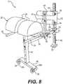
- a connector 52is shown in FIGS. 6 and 8 .
- a free end of the third beam 30 of the glute ham developer (GHD) exercise device 12is fitted or connected to the connector 52.
- the connector 52for example, can be a U-shaped bracket or section of box beam providing a slider configured to cooperate with a vertical post 46 of the rig exercise device 14.
- the connector 52can be configured to slide up and down on the vertical post 46, and then be locked in position with a removable locking pin 53 ( FIG. 8 ).
- the connector 52for example, can be connected to the free end of the third horizontal beam 30 of the glute ham developer (GHD) exercise device 12.
- GLDglute ham developer
- a boltFIG. 8 connects the connector 52 to the free end of the third horizontal beam 30.
- the locking pin 53 of the connector 53is configured to cooperate with a selected hole in a series of holes provided on each side of the vertical post 46 along a length thereof (e.g. the holes can be provided along a portion or the entire length of the vertical post 46). This allows the height of the connector 52 to be adjusted. For example, the height of the connector 52 is adjusted so that the third horizontal beam 30 of the glute ham developer (GHD) exercise device 12 is oriented horizontally.
- GDDglute ham developer
- the exercise device 10can be an integrated exercise unit with the glute ham developer (GHD) exercise device 12 connected to the rig exercise device 14.
- the exercise device 10can be an integrated unit with the glute ham developer (GHD) exercise device 12 and rig exercise device 14 assembled together at the same time.
- the glute ham developer (GHD)can be an accessory that to be later added to an existing already assembled rig exercise device 14.
- FIGS. 9 thru 14A stand alone glute ham developer (GHD) device 112 is shown in FIGS. 9 thru 14 .
- the stand alone glute ham developer (GHD) exercise device 112comprises a first vertical post 116.
- a first horizontal beam 118is connected (e.g. bolted, welded and/or fastened) to an upper end of the first vertical post 116, and oriented transversely relative to a length of the glute ham developer (GHD) exercise device 112.
- a second horizontal beam 120is connected (e.g. bolted, welded, and/or fastened) to a lower end of the first vertical post 116, and oriented transversely relative to a length of the glute ham developer (GHD) exercise device 112.
- the ends of the second horizontal beam 120serve as outriggers for stabilizing the glute ham developer (GHD) exercise device 12 on the floor.
- a pair of stabilizer beams 120Acan be each connected to respective ends of the second horizontal beam 120.
- the stabilizer beams 120Aare oriented transversely relative to the second horizontal beam 120, and extend forwardly and outwardly in front of the stand alone glute ham developer (GHD) device 112.
- GDDstand alone glute ham developer
- a pair of reinforcing members 120Bare connected between the second beam 120 and each stabilizer beams 120A to reinforce the structural connection and the relative orientation therebetween.
- a pair of gusset plates 120Ccan connect the second horizontal beam 120 to the first vertical post 116, and reinforce this structural connection.
- a split cushion 122is connected to and supported on top of the first horizontal beam 118.
- the split cushion 122comprises a pair of split cushions 124, 124 separated apart a distance.
- the bottom of each split cushion 124, 124is provided with a slider (not shown) cooperating with the first horizontal beam 118, and each having a locking pin (not shown) to allow the split cushions 124, 124 to be adjusted further apart or closer together.
- the locking pinscooperate with one of a series of holes (not shown) provided in the first horizontal beam 118.
- a pair of handles126, 126are connected (e.g. bolted, welded, and/or fastened) to the first horizontal beam 118, and extend outwardly in front of the glute ham developer (GHD) exercise device 112.
- the pair of handles 126, 126can be oriented horizontally.
- a pair of rollers 120Dare each fitted to the bottom of each stabilizer beam 120A to allow moving the glute ham developer (GHD) exercise device 112.
- the rollers 120Dcan be replaced with feet (e.g. rubber or plastic resilient gripping feet).
- the stand alone glute ham developer (GHD) exercise device 112also comprises a third horizontal beam 130 connected (e.g. bolted, welded, and/or fastened) to the first vertical post 116.
- a second vertical post 132is connected to the third horizontal beam 130.
- the second vertical post 132is connected in a manner that it can be adjusted or slid along a length of the third horizontal beam 130 to move the second vertical post 132 closer to or further away from the first vertical post 116 and the split cushion 122 to accommodate the length of the legs of the particular user.
- a slider 134is connected (e.g. bolted, welded, and/or fastened) to a lower end of the second vertical post 132.
- the slider 134is made from a section of box beam having inner dimensions the same or slightly larger than the outer dimensions of the third horizontal beam 130 to allow the slider 134 to slide along the length of the third horizontal beam 130.
- the slider 134is fitted with a locking pin 136 configured to cooperate with one of a series of holes provided along the length of the third horizontal beam 130 to adjust or change the location of the slider 134 and second vertical post 132 on the third horizontal beam 130.
- the second vertical post 132is provided with an ankle grip device, for example, a pair of shafts 138 that are spaced apart and located at different heights on the second vertical post 132.
- the second vertical post 132is provided with two holes to accommodate the shafts 138, 138, and the shafts are connected (e.g. bolted, welded, and/or fastened) to the second vertical post 132.
- a shafts 138, 138can be centered on the vertical post 132 to provide opposed ends extending outwardly from the vertical post 132.
- a pair of cylindrical-shaped cushions 140, 140can be provided on the ends of the shafts 138, 138.
- a foot plate 142is connected (e.g. bolted, welded, and/or fastened) via a support 144 (e.g. bar, beam, or plate) to the second vertical post 132.
- the foot plate 142is oriented vertically and spaced a predetermined distance from the cushions 140.
- the first vertical post 116, second vertical post 132, first horizontal beam 118, second horizontal beam 120, and third horizontal beam 130can be made from sections of box beams (e.g. metal, steel, aluminum, plastic, composite, fiberglass, carbon graphite, Kevlar, or other suitable structural material) connected together by bolting, welding, and/or fastening (e.g. using conventional or custom made fasteners and/or connectors).
- box beamse.g. metal, steel, aluminum, plastic, composite, fiberglass, carbon graphite, Kevlar, or other suitable structural material
- a third vertical post 117is connected to the free end of the third horizontal beam 130, for example, by a reinforcing plate 117A and bolts or rivets.
- a fourth horizontal beam 117is connected (e.g. by welding, bolting, or mechanical fastener(s)) to the bottom of the third vertical post 117 and oriented transversely relative to the third horizontal beam 130.
- a pair of sets of trunnions 128Ae.g. plates and axle
- a pair of gusset plates 121Ccan connect the fourth horizontal beam to the third vertical post, and reinforce the structural connection therebetween.
- a fifth horizontal beam 131can connect between the second horizontal beam 120 and the fourth horizontal beam 121 to create a frame arrangement to strengthen the structure of the stand alone glute ham exercise device 112.
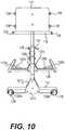
- FIGS. 15 thru 17The operation and use of the glute ham exercise device 12 (or glute ham exercise device 112) is shown in FIGS. 15 thru 17 .
- a usersits on the split cushion 124, and places his or her ankles between the sets of cushions 40 as shown.
- the userthen leans backwards to the extended horizontal position, as shown in FIG. 16 .
- the userfurther leans backwards to extend his or her back further downward at an angle, as shown in FIG. 17 .
- the userthen returns to the sitting upward position shown in FIG. 15 , and then repeats the entire operation a number of cycles.
Landscapes
- Health & Medical Sciences (AREA)
- Orthopedic Medicine & Surgery (AREA)
- General Health & Medical Sciences (AREA)
- Physical Education & Sports Medicine (AREA)
- Engineering & Computer Science (AREA)
- Biomedical Technology (AREA)
- Neurology (AREA)
- Pulmonology (AREA)
- Life Sciences & Earth Sciences (AREA)
- Biophysics (AREA)
- Rehabilitation Tools (AREA)
- Road Signs Or Road Markings (AREA)
Description
- An exercise device, in particular an exercise device configured to strengthen the hamstring and gluteus, for example, a Glute Ham Developer (GHD).
- In the past, there has existed various weight lifting equipment for exercising and developing various muscles and muscle groups of the body. For example,
US 5,306,220 is a universal-use knock-down weight-lifting frame and exercise system. The system comprises a lat hold-down having a main leg, a side leg extending transversely to the main leg, and a vertical accessory post integrally attached to side leg and extending substantially transversely to both side leg and main leg. Side leg has open ends for receiving accessories such as a seat support. The seat support has a substantially U-shaped base and a seat-supporting upright. The upright includes holes and adjustably supports a seat for vertical movement relative to a base by means of selectively placing a pin through a desired one of holes. There is a continuing need for new types and configurations of exercise equipment for exercising and developing specific portions of the body, for example, to strengthen the hamstring and gluteus. - According to the invention, a glute ham developer (GHD) exercise device as claimed in claim 1 is provided.
- Wherein the exercise device is configured to strengthen the hamstring and gluteus.
- The glute ham developer (GHD) exercise device comprising a vertical post connected to a horizontal beam.
- The glute ham developer (GHD) exercise device comprising a vertical post, one or more pads supported by the vertical post, and a horizontal beam connected to the vertical post.
- The glute ham developer (GHD) exercise device comprising a first vertical post, one or more pads supported by the first vertical post, a horizontal beam connected to the vertical post, a second vertical post connected to the horizontal beam, and one or more foot pegs connected to the second vertical post.
- The glute ham developer (GHD) exercise device can be connected to another exercise device such as a rig or rack.
- The glute ham developer (GHD) exercise device, another exercise device such as a rig or rack, and a connector being configured to connect the glute ham developer (GHD) exercise device to the another exercise device such as a rig or rack.
- The exercise device is configured to strengthen the ham string and gluteus. For example, the exercise device is a glute ham developer (GHD) exercise device.
- For example, the glute ham developer (GHD) exercise device can be a stand alone glute ham developer (GHD) exercise device. As another example, the glute ham developer (GHD) exercise device can be an exercise attachment device configured to be attached to another support such as a post connected to a floor, wall, and/or ceiling, or another exercise device (another piece of exercise piece of equipment). As a further example, the exercise device comprises glute ham developer (GHD) exercise device connected together or integrated together with other exercise equipment or exercise equipment stations (e.g. exercise rig, rack, and stand).
- The glute ham developer (GHD) exercise device, for example, can comprise or consist of a first vertical post connected to an upper first horizontal beam and lower second horizontal beam. The first horizontal beam and second horizontal beam can be oriented transversely relative to a length of the glute ham developer (GHD) exercise device. A support pad, for example, a split pad can be connected to and supported on top of the first horizontal post. For example, the first horizontal beam, oriented transverse relative to a length of the exercise device, is connected to an upper end of the first vertical post (e.g. by welding or bolting), and a pair of split pads are supported by the first horizontal beam. The split pads and first horizontal beam can be configured so that the split pads can be moved or adjusted closer together or further apart to accommodate a particular user. The support pad or split pad, for example, can be cylindrical-shaped (e.g. partial or one-half cylinder-shaped) with the round side facing upwardly. The second horizontal beam is connected (e.g. bolted or welded) to a bottom end of the first vertical post. The second horizontal beam is oriented transversely relative to a length of the exercise device to provide stability (e.g. ends acting like outriggers).
- A third horizontal beam is connected to the first vertical post (e.g. by welding or bolting). A second vertical post is connected to the first horizontal beam. For example, the second vertical post is connected to the third horizontal beam in a manner to allow the second vertical post to be moved (e.g. slid on third horizontal beam) or adjusted closer to or further away from the first vertical post or split pads to accommodate the leg lengths of a particular user. For example, a lower end of the second vertical post is connected (e.g. bolted or welded) to a slider (e.g. section of box beam) configured to be supported by or surrounding the second horizontal beam. For example, the slider is fitted with a locking pin to cooperate with one of a series of holes provided along a length of the third horizontal beam to allow adjustment of the slider along the third horizontal beam and locking same into a selected position.
- The second vertical post, for example, is fitted with an ankle grip device. The ankle grip device, for example, can be provided by one or more ankle pegs. For example, a horizontal transversely oriented shaft is fitted through a hole in the vertical post and connected thereto (e.g. by bolting or welding). The shaft can be centered on the second vertical post providing opposed ends extending outwardly from the second vertical post. A pair of ankle pads (e.g. cylindrical-shaped pads) are provided on the opposed ends of the horizontal shaft, and configured to rotate. Another horizontal transverse oriented shaft with a pair of ankle pads can be provided at a different height on the second vertical post relative to the other horizontal shaft. The two shafts and respective pairs of ankle pads together being configured to grip and restrain the ankles of a user during use of the exercise device.
- The third horizontal beam is connected to one end to the first vertical post, and can be connected at an opposite end to another support. For example, the support can be a post, for example, supported on or connected to a floor, wall, and/or ceiling. Alternatively, the support can be a part or component of another exercise device or combined exercise device. For example, the another exercise device can be a rig or rack, in particular an exercise rig or rack. For example, the rig can comprise multiple posts connected together by beams, joists, or other suitable structure connecting together the posts into an integrated rig structure. As another example, the rack can comprise posts connected together by beams, joists, or other suitable structure, and configured to hold, store, or otherwise support weights, in particular free weights.
- The glute ham developer (GHD) exercise device comprises a connector for connecting the exercise device to another exercise device such as a rig or rack. For example, a free end of the third horizontal beam is provided with a connector. The connector, for example, is configured to connect to a vertical post of the rig or rack. For example, the connector is a slider connected (e.g. bolted or welded) to the free end of the third horizontal beam. The position of the slider can be adjusted up or down the post for example, to place the third horizontal beam in a level horizontal position, and then lock same into position. For example, the slider is section of box beam or a U-shaped channel provided with a removable locking pin that passes through a pair of holes in the box beam or U-shaped channel and a cooperating pair of respective holes in the vertical post of the rig or rack. The vertical post of the rig or rack is provided with multiple pairs of spaced apart holes at different heights to allow height adjustment of the slider and respectively the height of the free end of the third horizontal beam.
FIG. 1 is a perspective view of an exercise device.FIG. 2 is a front elevational view of the exercise device shown inFIG. 1 .FIG. 3 is a rear elevational view of the exercise device shown inFIG. 1 .FIG. 4 is a top planar view of the exercise device shown inFIG. 1 .FIG. 5 is a bottom planar view of the exercise device shown inFIG. 1 .FIG. 6 is a side elevational view of the exercise device shown inFIG. 1 FIG. 7 is an opposite side elevational view of an exercise device shown inFIG. 1 .FIG. 8 is a perspective view of an exercise attachment device.FIG. 9 is a front view of the exercise attachment device shown inFIG. 8 .FIG. 10 is a rear view of the exercise attachment device shown inFIG. 9 .FIG. 11 is a top planar view of the exercise attachment device shown inFIG. 8 .FIG. 12 is a bottom planar view of the exercise attachment device shown inFIG. 8 .FIG. 13 is a side elevational view of a stand alone exercise device.FIG. 14 is an opposite side elevational view of the stand alone exercise device shown inFIG. 13 .FIG. 15 is a side diagrammatic view illustrating a user in a partial sitting position on the exercise device.FIG. 16 is a side diagrammatic view illustrating a user in an extended laid out position on the exercise device.FIG. 17 is a side diagrammatic view illustrating a user in a back extended downwardly position on the exercise device.- An
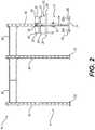
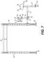
exercise device 10 is shown inFIGS. 1 thru 7 . Theexercise device 10 comprises or consists of a glute ham developer (GHD)exercise device 12 connected to arig exercise device 14. The glute ham developer (GHD)exercise device 12 andrig exercise device 14 are shown integrated together as a single exercise unit when assembled together. - The glute ham developer (GHD)
exercise device 12 comprises a firstvertical post 16. A firsthorizontal beam 18 is connected (e.g. bolted, welded and/or fastened) to an upper end of the firstvertical post 16, and oriented transversely relative to a length of the glute ham developer (GHD)exercise device 12. A secondhorizontal beam 20 is connected (e.g. bolted, welded, and/or fastened) to a lower end of the firstvertical post 16, and oriented transversely relative to a length of the glute ham developer (GHD)exercise device 12. The ends of the secondhorizontal beam 20 serve as outriggers for stabilizing the glute ham developer (GHD)exercise device 12 on the floor. - A support cushion, for example, a
split cushion 22 is connected to and supported on top of the firsthorizontal beam 18. Thesplit cushion 22 comprises a pair of split cushions 24, 24 separated apart a distance. The bottom of eachsplit cushion first beam 18, and each having a locking pin (not shown) to allow the split cushions 24, 24 to be adjusted further apart or closer together. The locking pins cooperate with one of a series of holes (not shown) provided in the firsthorizontal beam 18 to change or adjust the position and separation distance of the split cushions 24, 24 along the length of the firsthorizontal beam 18. - A pair of
handles horizontal beam 18, and extend outwardly in front of the glute ham developer (GHD)exercise device 12. The pair ofhandles - A pair of
rollers horizontal beam 20 by trunnion arrangement 28A (e.g. pair of plates and axle supporting therollers 28, 28) to allow moving the glute ham developer (GHD)exercise device 12. Therollers ham exercise device 12 is separated from therig exercise device 14, the glute ham exercise device can be tilted at an angle to place therollers rollers exercise device 12. - The glute ham developer (GHD)
exercise device 12 also comprises a thirdhorizontal beam 30 connected (e.g. bolted, welded, and/or fastened) to the firstvertical post 16. - A second
vertical post 32 is connected to the thirdhorizontal beam 30. For example, the secondvertical post 32 is connected in a manner that its position can be adjusted (e.g. by sliding) along a length of the thirdhorizontal beam 30 to move the secondvertical post 32 closer to or further away from the firstvertical post 16 and splitcushion 22 to adjust for the length of the legs of the user. Aslider 34 is connected (e.g. bolted, welded, and/or fastened) to a lower end of the secondvertical post 32. For example, theslider 34 is made from a section of box beam having inner dimensions the same as or slightly larger than the outer dimensions of the thirdhorizontal beam 30 to allow theslider 34 to slide along the length of thethird beam 30. Theslider 34 is fitted with a lockingpin 36 configured to cooperate with one of a series of holes provided along the length of thethird beam 30 to adjust or change the location of theslider 34 and secondvertical post 32 on thethird beam 30 relative to the firstvertical post 16 and splitcushion 22. - The second
vertical post 32 is fitted with an ankle grip device, for example, comprising a pair ofshafts 38 that are spaced apart and located at different heights on the secondvertical post 32. For example, the secondvertical post 32 is provided with two holes to accommodate theshafts vertical post 32. For example, a center of each shaft is located at the secondvertical post 32 with opposite ends extending outwardly therefrom. A pair of cylindrical-shapedcushions shaft 38. Theshafts vertical post 32 in a manner to accommodate the ankles of a user between upper and lower sets of the pair ofcushions - A
foot plate 42 is connected (e.g. bolted, welded, and/or fastened) via a support 44 (e.g. bar, beam, or plate) to the secondvertical post 32. Thefoot plate 42 can be oriented vertically and spaced a predetermined distance from thecushions 40 to accommodate the feet of the user. - The first
vertical post 16, secondvertical post 32, firsthorizontal beam 18, secondhorizontal beam 20, and thirdhorizontal beam 30, for example, can be made from sections of box beams (e.g. metal, steel, aluminum, plastic, composite, fiberglass, carbon graphite, Kevlar, or other suitable structural material) connected together by bolting, welding, forming, molding and/or fastening (e.g. using conventional or custom made fasteners and/or connectors). - The
rig exercise device 14 comprises spaced apartvertical posts 46 connected together by joist members (e.g. doublelength joist members 48, regular length joist members 49) located at the upper ends of the vertical posts 46. Thevertical posts 46, for example, can be box beams (e.g. made of metal, steel, aluminum, plastic, composite, fiberglass, carbon graphite, Kevlar, or other suitable structural material). Thejoist members joist members vertical posts 46 to assemble therig exercise device 14. - The
vertical posts 46 are provided withfoot plates 50 at lower ends thereof for anchoring thevertical posts 46 to the floor. For example, thefoot plates 50 can be provided with through holes for bolting and anchoring thefoot plates 50 integrated with thevertical posts 46 to the floor. - The glute ham developer (GHD)
exercise device 12 can be connected to theexercise rig device 14. For example, the thirdhorizontal beam 30 of the glute ham developer (GHD)exercise device 12 can be bolted, welded, and/or fastened. The fastener, for example, can be a conventional or custom made fastener or connector. The connection can be permanent (e.g. welded), or configured to be assembled and disassembled (e.g. bolted). - For example, a
connector 52 is shown inFIGS. 6 and8 . A free end of thethird beam 30 of the glute ham developer (GHD)exercise device 12 is fitted or connected to theconnector 52. Theconnector 52, for example, can be a U-shaped bracket or section of box beam providing a slider configured to cooperate with avertical post 46 of therig exercise device 14. Theconnector 52 can be configured to slide up and down on thevertical post 46, and then be locked in position with a removable locking pin 53 (FIG. 8 ). - The
connector 52, for example, can be connected to the free end of the thirdhorizontal beam 30 of the glute ham developer (GHD)exercise device 12. For example, a bolt (FIG. 8 ) connects theconnector 52 to the free end of the thirdhorizontal beam 30. - The locking
pin 53 of theconnector 53 is configured to cooperate with a selected hole in a series of holes provided on each side of thevertical post 46 along a length thereof (e.g. the holes can be provided along a portion or the entire length of the vertical post 46). This allows the height of theconnector 52 to be adjusted. For example, the height of theconnector 52 is adjusted so that the thirdhorizontal beam 30 of the glute ham developer (GHD)exercise device 12 is oriented horizontally. - The
exercise device 10 can be an integrated exercise unit with the glute ham developer (GHD)exercise device 12 connected to therig exercise device 14. For example, theexercise device 10 can be an integrated unit with the glute ham developer (GHD)exercise device 12 andrig exercise device 14 assembled together at the same time. Alternatively, the glute ham developer (GHD) can be an accessory that to be later added to an existing already assembledrig exercise device 14. - A stand alone glute ham developer (GHD)
device 112 is shown inFIGS. 9 thru 14 . - The stand alone glute ham developer (GHD)
exercise device 112 comprises a firstvertical post 116. A firsthorizontal beam 118 is connected (e.g. bolted, welded and/or fastened) to an upper end of the firstvertical post 116, and oriented transversely relative to a length of the glute ham developer (GHD)exercise device 112. A secondhorizontal beam 120 is connected (e.g. bolted, welded, and/or fastened) to a lower end of the firstvertical post 116, and oriented transversely relative to a length of the glute ham developer (GHD)exercise device 112. The ends of the secondhorizontal beam 120 serve as outriggers for stabilizing the glute ham developer (GHD)exercise device 12 on the floor. - A pair of stabilizer beams 120A can be each connected to respective ends of the second
horizontal beam 120. The stabilizer beams 120A are oriented transversely relative to the secondhorizontal beam 120, and extend forwardly and outwardly in front of the stand alone glute ham developer (GHD)device 112. A pair of reinforcing members 120B are connected between thesecond beam 120 and each stabilizer beams 120A to reinforce the structural connection and the relative orientation therebetween. - A pair of gusset plates 120C can connect the second
horizontal beam 120 to the firstvertical post 116, and reinforce this structural connection. - A
split cushion 122 is connected to and supported on top of the firsthorizontal beam 118. Thesplit cushion 122 comprises a pair of split cushions 124, 124 separated apart a distance. The bottom of eachsplit cushion horizontal beam 118, and each having a locking pin (not shown) to allow the split cushions 124, 124 to be adjusted further apart or closer together. The locking pins cooperate with one of a series of holes (not shown) provided in the firsthorizontal beam 118. - A pair of handles126, 126 are connected (e.g. bolted, welded, and/or fastened) to the first
horizontal beam 118, and extend outwardly in front of the glute ham developer (GHD)exercise device 112. The pair ofhandles exercise device 112. Alternatively, the rollers 120D can be replaced with feet (e.g. rubber or plastic resilient gripping feet). - The stand alone glute ham developer (GHD)
exercise device 112 also comprises a thirdhorizontal beam 130 connected (e.g. bolted, welded, and/or fastened) to the firstvertical post 116. - A second
vertical post 132 is connected to the thirdhorizontal beam 130. For example, the secondvertical post 132 is connected in a manner that it can be adjusted or slid along a length of the thirdhorizontal beam 130 to move the secondvertical post 132 closer to or further away from the firstvertical post 116 and thesplit cushion 122 to accommodate the length of the legs of the particular user. Aslider 134 is connected (e.g. bolted, welded, and/or fastened) to a lower end of the secondvertical post 132. For example, theslider 134 is made from a section of box beam having inner dimensions the same or slightly larger than the outer dimensions of the thirdhorizontal beam 130 to allow theslider 134 to slide along the length of the thirdhorizontal beam 130. Theslider 134 is fitted with alocking pin 136 configured to cooperate with one of a series of holes provided along the length of the thirdhorizontal beam 130 to adjust or change the location of theslider 134 and secondvertical post 132 on the thirdhorizontal beam 130. - The second
vertical post 132 is provided with an ankle grip device, for example, a pair ofshafts 138 that are spaced apart and located at different heights on the secondvertical post 132. For example, the secondvertical post 132 is provided with two holes to accommodate theshafts vertical post 132. Ashafts vertical post 132 to provide opposed ends extending outwardly from thevertical post 132. A pair of cylindrical-shapedcushions shafts - A
foot plate 142 is connected (e.g. bolted, welded, and/or fastened) via a support 144 (e.g. bar, beam, or plate) to the secondvertical post 132. Thefoot plate 142 is oriented vertically and spaced a predetermined distance from thecushions 140. - The first
vertical post 116, secondvertical post 132, firsthorizontal beam 118, secondhorizontal beam 120, and thirdhorizontal beam 130, for example, can be made from sections of box beams (e.g. metal, steel, aluminum, plastic, composite, fiberglass, carbon graphite, Kevlar, or other suitable structural material) connected together by bolting, welding, and/or fastening (e.g. using conventional or custom made fasteners and/or connectors). - As shown in
FIG. 13 , a thirdvertical post 117 is connected to the free end of the thirdhorizontal beam 130, for example, by a reinforcing plate 117A and bolts or rivets. A fourthhorizontal beam 117 is connected (e.g. by welding, bolting, or mechanical fastener(s)) to the bottom of the thirdvertical post 117 and oriented transversely relative to the thirdhorizontal beam 130. A pair of sets of trunnions 128A (e.g. plates and axle) are connected to the fourthhorizontal beam 121, andsupport rollers 128 for moving the free standing gluteham exercise device 112 by tilting thereof. A pair of gusset plates 121C can connect the fourth horizontal beam to the third vertical post, and reinforce the structural connection therebetween. - A fifth
horizontal beam 131 can connect between the secondhorizontal beam 120 and the fourthhorizontal beam 121 to create a frame arrangement to strengthen the structure of the stand alone gluteham exercise device 112. - The operation and use of the glute ham exercise device 12 (or glute ham exercise device 112) is shown in
FIGS. 15 thru 17 . - As shown in
FIG. 15 , a user sits on thesplit cushion 124, and places his or her ankles between the sets ofcushions 40 as shown. The user then leans backwards to the extended horizontal position, as shown inFIG. 16 . The user further leans backwards to extend his or her back further downward at an angle, as shown inFIG. 17 . The user then returns to the sitting upward position shown inFIG. 15 , and then repeats the entire operation a number of cycles.
Claims (15)
- A glute ham developer (GHD) exercise device (12), the device comprising:a first vertical post (16) located on a center longitudinal axis of the device;a support cushion (22) connected to and located above the first vertical post (16),a first horizontal beam (18) connected to an upper end of the first vertical post (16) and oriented transversely relative to the center longitudinal axis of the exercise device for supporting the support cushion (22);a second horizontal beam (20) connected to a lower end of the first vertical post (16) and oriented transversely relative to the center longitudinal axis of the exercise device for stabilizing the glute ham developer (GHD) exercise device (12) on the floor;a third horizontal beam (30) connected at a first end to the first vertical post (16) and oriented along the center longitudinal axis of the exercise device, the third horizontal beam connected to the first vertical post (16) at a position along a length of the first vertical post (16) located below the first horizontal beam (18) and above the second horizontal beam (20);a second vertical post (32) located on the center longitudinal axis of the exercise device and connected to and extending directly upward from the third horizontal beam (30);an ankle grip device (38) connected to the second vertical post (32); anda connector (52) for connecting a second end of the third horizontal beam (30) to a third vertical post (46,117) for supporting the third horizontal beam (30);wherein the second vertical post (32) is located between the first vertical post (16) and the third vertical post (46,117).
- The device according to claim 1, further comprising another exercise device (14) connected to the glute ham developer (GHD) exercise device (12).
- The device according to claim 2, wherein the another exercise device (14) is a rig or rack exercise device.
- The device according to claim 1, wherein the connector (52) is a slider for adjusting the position of the connector along the third vertical post (46).
- The device according to claim 4, wherein the third vertical post (46) is a post of another exercise device (14).
- The device according to claim 5, wherein the another exercise device (14) is a rig or rack exercise device.
- The device according to any preceding claim, wherein the ankle grip device comprises a pair of shafts (38) that are spaced apart and located at different heights on the second vertical post (32).
- The device according to claim 7, wherein each shaft (38) of the ankle support device comprises a pair of cushions (40) provided on ends of the shaft.
- The device according to claim 8, wherein the shafts (38) are spaced apart vertically on the second vertical post (32) in a manner to accommodate the ankles of a user between upper and lower sets of the pair of cushions (40).
- The device according to any preceding claim, further comprising a foot plate (42) connected to the second vertical post (32) by a support (44).
- The device according to claim 10, further comprising a support (44) connecting the foot plate (42) a distance from the second vertical post (32) for accommodating the feet of a user.
- The device according to any preceding claim, wherein the second vertical post (32) is connected to the third horizontal beam (30) by a slider (34) to allow adjusting the position of the second vertical post (32) along the third horizontal beam (30).
- The device according to any preceding claim, wherein the support cushion comprises a pair of split cushions (24) connected to the first horizontal beam (18) in a manner to allow the split cushions (24) to be moved closer together or separated further apart.
- The device according to any preceding claim, further comprising a set of handles (26) extending outwardly from the first horizontal beam (18).
- The device according to any preceding claim, wherein the third horizontal beam (30) is connected to a side of the first vertical post.
Applications Claiming Priority (2)
| Application Number | Priority Date | Filing Date | Title |
|---|---|---|---|
| US201361842438P | 2013-07-03 | 2013-07-03 | |
| US14/319,663US10420974B2 (en) | 2013-07-03 | 2014-06-30 | Exercise device |
Publications (2)
| Publication Number | Publication Date |
|---|---|
| EP2821112A1 EP2821112A1 (en) | 2015-01-07 |
| EP2821112B1true EP2821112B1 (en) | 2020-11-11 |
Family
ID=51167662
Family Applications (1)
| Application Number | Title | Priority Date | Filing Date |
|---|---|---|---|
| EP14175555.3AActiveEP2821112B1 (en) | 2013-07-03 | 2014-07-03 | Exercise device |
Country Status (3)
| Country | Link |
|---|---|
| US (1) | US10420974B2 (en) |
| EP (1) | EP2821112B1 (en) |
| CA (1) | CA2855466C (en) |
Families Citing this family (38)
| Publication number | Priority date | Publication date | Assignee | Title |
|---|---|---|---|---|
| US9259604B2 (en)* | 2012-08-31 | 2016-02-16 | Elwood Bernard Miller, Jr. | Exercise machine for performing squats |
| GB2518436B (en)* | 2013-09-23 | 2020-06-03 | Escape Fitness Ltd | A modular suspension beam for an exercise support frame |
| USD742979S1 (en)* | 2014-03-21 | 2015-11-10 | Theunis Johannes Post | Mobile multi-functional fitness frame |
| USD762789S1 (en)* | 2014-06-20 | 2016-08-02 | Fitness Engineers Pty. LTD | Fitness tower |
| USD762877S1 (en)* | 2014-06-23 | 2016-08-02 | 9143-8010 Québec Inc. | Post for clothes-line |
| US10953275B2 (en)* | 2014-08-04 | 2021-03-23 | Veronica PORTEROS DE LUZ | Hip thrusting exercise machine |
| USRE50362E1 (en)* | 2014-08-04 | 2025-04-08 | Veronica PORTEROS DE LUZ | Hip thrusting exercise machine |
| AU358298S (en)* | 2014-10-07 | 2014-10-20 | Fitness Eng Pty Ltd | A fitness assembly |
| USD763371S1 (en)* | 2014-12-05 | 2016-08-09 | Erin Michelle Fitzgerald | Round barrel pilates machine |
| USD794144S1 (en)* | 2015-06-01 | 2017-08-08 | Eleiko Sport, Inc. | Exercise rig |
| USD803956S1 (en)* | 2016-04-26 | 2017-11-28 | Bobby K. Sutton | Upper body exercise weight |
| USD805139S1 (en)* | 2016-05-25 | 2017-12-12 | Scott M. Bailey | Exercise bar |
| US11433270B2 (en) | 2017-11-15 | 2022-09-06 | Initiate Launch, Llc | Kettle bell and methods of use thereof |
| US10532241B2 (en) | 2016-11-15 | 2020-01-14 | Brian BOATNER | Kettle bell and methods of use thereof |
| CA3063130A1 (en) | 2017-05-12 | 2018-11-15 | Kormel LLC | Exercise apparatus for performing a gluteal bridge movement |
| US10500439B1 (en) | 2017-06-28 | 2019-12-10 | Aspen Integrative Kinetics, LLC | Exercise system |
| USD928253S1 (en) | 2018-03-22 | 2021-08-17 | Coulter Ventures, Llc. | Fitness rig |
| USD852907S1 (en)* | 2018-04-25 | 2019-07-02 | Coulter Ventures, LLC | Fitness rig |
| WO2019217447A1 (en) | 2018-05-07 | 2019-11-14 | Coulter Ventures Llc | Weightlifting machine |
| USD854637S1 (en)* | 2018-05-07 | 2019-07-23 | Coulter Ventures, LLC | Exercise stand |
| USD898844S1 (en) | 2018-07-31 | 2020-10-13 | Coulter Ventures, LLC | Cross-member for a climbing hold exercise rig |
| USD956890S1 (en) | 2019-05-06 | 2022-07-05 | Coulter Ventures, Llc. | Weightlifting assembly |
| USD908821S1 (en) | 2019-09-20 | 2021-01-26 | Coulter Ventures, Llc. | Display plate for weight rack |
| USD915534S1 (en)* | 2019-09-25 | 2021-04-06 | Coulter Ventures, Llc. | Weight rack with name plate |
| USD932572S1 (en) | 2019-10-21 | 2021-10-05 | Coulter Ventures, Llc. | Plate for weight rack |
| USD932573S1 (en) | 2019-12-13 | 2021-10-05 | Coulter Ventures, Llc. | Cross-member for weight rack |
| USD932574S1 (en) | 2020-01-13 | 2021-10-05 | Coulter Ventures, Llc. | Feet for a weight rack |
| USD944344S1 (en) | 2020-02-17 | 2022-02-22 | Coulter Ventures, Llc. | Foot for a weight rack |
| US11707642B2 (en)* | 2020-11-24 | 2023-07-25 | Blair Fourney | Apparatus for supported row exercise |
| US11759675B2 (en)* | 2021-02-18 | 2023-09-19 | Advanced Fitness Concepts, Inc. | Exercise apparatus for training muscles |
| US12076608B2 (en)* | 2021-03-17 | 2024-09-03 | David Peterson | Modular exercise system |
| USD1010033S1 (en) | 2022-05-23 | 2024-01-02 | Coulter Ventures, Llc. | Weight rack |
| US12251600B2 (en) | 2022-11-03 | 2025-03-18 | Christopher Hicks | Adjustable, compact glute hamstring developer exercise device |
| US20240207669A1 (en)* | 2022-12-23 | 2024-06-27 | Dominick Maurici | Exercise apparatus |
| US20240238638A1 (en)* | 2023-01-13 | 2024-07-18 | China 2 West Services Ltd. | Exercise equipment and related methods |
| CN120456958A (en)* | 2023-12-08 | 2025-08-08 | 狂热运动员必需品有限责任公司 | Apparatus and method for multi-configuration exercise device |
| US12420140B2 (en) | 2023-12-14 | 2025-09-23 | Life Fitness, Llc | Exercise apparatuses for leg strengthening |
| US12370399B1 (en)* | 2024-12-13 | 2025-07-29 | Ningbo Danshui Trading Co., Ltd | Multifunctional fitness pad |
Family Cites Families (60)
| Publication number | Priority date | Publication date | Assignee | Title |
|---|---|---|---|---|
| US3134592A (en)* | 1962-05-31 | 1964-05-26 | Robert V Sharkey | Adjustable foot-restraining exercising device for attachment to the footboard of a bed |
| US3567218A (en)* | 1968-05-29 | 1971-03-02 | Edwin S Johnson | Bending exercising device |
| US3682475A (en)* | 1970-06-04 | 1972-08-08 | Norman E Walker | Exercise device having foot restraining means |
| US4185816A (en)* | 1977-03-15 | 1980-01-29 | Bernstein Morton J | Sit-up exercise apparatus |
| US4116434A (en)* | 1977-03-15 | 1978-09-26 | Bernstein Morton J | Sit-up exercise apparatus |
| US4210322A (en)* | 1977-10-03 | 1980-07-01 | Pritchard Michael E | Portable tumbling mat |
| US4286782A (en)* | 1978-10-26 | 1981-09-01 | Fuhrhop Marious P | Multi-purpose exercise enhancing device |
| US4398713A (en)* | 1981-08-03 | 1983-08-16 | Ellis Charles R | Exercising device |
| US4515361A (en)* | 1983-02-04 | 1985-05-07 | Michael Codella | Exercising appliance |
| DE3460755D1 (en)* | 1983-04-06 | 1986-10-23 | Hans Werner Matheisen | Body exercise apparatus |
| US4542900A (en)* | 1983-10-04 | 1985-09-24 | Versatile Equipment Co., Inc. | Exercise or therapy device or apparatus |
| US4679788A (en)* | 1985-12-02 | 1987-07-14 | Adler David M | Exercise device |
| US4884804A (en)* | 1986-07-02 | 1989-12-05 | Chad Fenwick | Exercise apparatus |
| US4830367A (en) | 1987-01-21 | 1989-05-16 | Spine Design, Inc. | Exercise device |
| US4848740A (en)* | 1988-02-16 | 1989-07-18 | Rio-Flex Corp. | Abdominal musculature development device |
| US5106083A (en)* | 1990-12-10 | 1992-04-21 | Hall Henry V | Exercise device with protrusion |
| US5135459A (en)* | 1991-06-03 | 1992-08-04 | Perry Jr Leroy R | Adductor contraction exercise apparatus and method |
| US5306220A (en) | 1992-06-11 | 1994-04-26 | Kearney David E | Knock-down weight-lifting frame and exercise system |
| US5263919A (en)* | 1992-11-12 | 1993-11-23 | Hollenback George M | Single leg squat machine |
| US5584786A (en)* | 1993-07-07 | 1996-12-17 | Almeda; Thomas M. | Abdominal exercise device |
| SE511529C2 (en)* | 1993-09-22 | 1999-10-11 | Good Health Inc 4 | Body traction table for treatment of, among other things, back problems |
| US5623949A (en)* | 1994-05-31 | 1997-04-29 | Kostich; Jeffrey V. | Patient positioning device |
| US5433220A (en)* | 1994-05-31 | 1995-07-18 | Kostich; Jeffrey V. | Patient grip positioner |
| US5570957A (en) | 1994-06-24 | 1996-11-05 | Body-Solid, Inc. | Bushing arrangement for carriage on exercise equipment |
| US5935050A (en)* | 1994-10-05 | 1999-08-10 | Shahan; Emory Lee "Buzz" | Back strengthening method and apparatus |
| USD369841S (en)* | 1994-12-13 | 1996-05-14 | Lien-Chuan Yang | Door mountable sit up exerciser |
| US6231487B1 (en)* | 1997-12-26 | 2001-05-15 | John P. Diamond, Jr. | Apparatus for stimulating hamstring contraction to effect optimum abdominal muscle conditioning |
| US6254517B1 (en)* | 1999-11-12 | 2001-07-03 | Robert D. Kennedy | Multiple exercise device |
| US6547704B2 (en)* | 2000-02-16 | 2003-04-15 | John Parrillo | Muscle stretching apparatus |
| US6468188B1 (en)* | 2000-03-30 | 2002-10-22 | Jam'n Fitness Corp. | Exercise apparatus for gluteus and hamstring muscles |
| US6692418B2 (en)* | 2000-11-18 | 2004-02-17 | Backhealth Usa | Back strengthening apparatus |
| US20020128131A1 (en) | 2000-12-18 | 2002-09-12 | Wu Shen Yi | Waist/back exerciser |
| US6592497B2 (en)* | 2001-02-26 | 2003-07-15 | Jeffrey C. Greenheck | Leg barbell |
| US8007414B2 (en)* | 2001-07-16 | 2011-08-30 | Riney Dennis P | Exercise machine to train the hamstring group of muscles |
| US7407467B2 (en)* | 2003-09-22 | 2008-08-05 | Diamond Jr Jack | Abdominal and hamstring muscle strength conditioning device |
| US20050159279A1 (en)* | 2004-01-16 | 2005-07-21 | Stangler Ari J. | Body support for exercising and stretching |
| US7172540B2 (en)* | 2004-05-27 | 2007-02-06 | Hai Minh Nguyen | Portable abdominal exerciser |
| US7691042B2 (en)* | 2004-11-29 | 2010-04-06 | Raffaele Martini Pandozy | Abdominal exercising apparatus and method |
| US20060116262A1 (en)* | 2004-11-29 | 2006-06-01 | Pandozy Raffaele M | Biodynamic apparatus for performing correct SIT-UP and LEGS-UP exercises and methods |
| US20070197360A1 (en)* | 2005-08-29 | 2007-08-23 | Dahlene Rester | Machine for improved curve and stretching device |
| US20070072749A1 (en)* | 2005-09-29 | 2007-03-29 | Lay Kenneth G | Heel cradle exercise device and footrest |
| US7384383B2 (en)* | 2005-10-28 | 2008-06-10 | J.E.M. Concept International, Inc. | Abdominal bench |
| US7361128B2 (en)* | 2006-06-27 | 2008-04-22 | Chih-Liang Chen | Exercising apparatus |
| US7367928B2 (en)* | 2006-08-28 | 2008-05-06 | Shimon Storch | Exercise device |
| US7699763B2 (en)* | 2006-10-12 | 2010-04-20 | Perry Jr Leroy R | Abductor contraction, variable leg/knee/thigh/trunk and spinal decompression exercise and rehabilitation apparatus and method |
| US20090264265A1 (en) | 2006-12-19 | 2009-10-22 | Bret Contreras | Exercise Apparatus and Methods of Use |
| US7637851B1 (en)* | 2008-11-11 | 2009-12-29 | Junior Lormil | Upper body exercising assembly |
| USD613804S1 (en)* | 2009-01-29 | 2010-04-13 | Charles Perez | Multi-exercise device |
| KR200445958Y1 (en)* | 2009-03-09 | 2009-09-14 | 김기수 | Multipurpose fitness equipment |
| US8491450B2 (en)* | 2009-11-13 | 2013-07-23 | Leroy R. Perry, Jr. | Rotary, adjustable body exercise equipment |
| US9192801B1 (en)* | 2009-12-08 | 2015-11-24 | Vassili Gouloubev | Exercise support system |
| US8936540B2 (en)* | 2011-02-11 | 2015-01-20 | Martin Lanell KUECKELHAN | Portable exercise device for the posterior muscle chain |
| USD685867S1 (en)* | 2011-02-15 | 2013-07-09 | Brett David Mehlman | Glute machine |
| CN202070085U (en)* | 2011-05-19 | 2011-12-14 | 厦门宙隆运动器材有限公司 | Stretcher |
| US9119984B2 (en)* | 2012-08-01 | 2015-09-01 | Gregory Paul Littell | Abdominal/back muscle exercise device |
| US9211431B2 (en)* | 2012-08-30 | 2015-12-15 | Group X, LLC | Exercise machine |
| US9259604B2 (en)* | 2012-08-31 | 2016-02-16 | Elwood Bernard Miller, Jr. | Exercise machine for performing squats |
| USD803958S1 (en)* | 2016-09-14 | 2017-11-28 | Coulter Ventures, LLC | Abdominal exercise mat |
| US10130838B2 (en)* | 2016-11-30 | 2018-11-20 | Robert Murrell | Abdominal exercise assembly |
| CA3063130A1 (en)* | 2017-05-12 | 2018-11-15 | Kormel LLC | Exercise apparatus for performing a gluteal bridge movement |
- 2014
- 2014-06-30USUS14/319,663patent/US10420974B2/ennot_activeExpired - Fee Related
- 2014-07-02CACA2855466Apatent/CA2855466C/enactiveActive
- 2014-07-03EPEP14175555.3Apatent/EP2821112B1/enactiveActive
Non-Patent Citations (1)
| Title |
|---|
| None* |
Also Published As
| Publication number | Publication date |
|---|---|
| EP2821112A1 (en) | 2015-01-07 |
| CA2855466C (en) | 2021-05-18 |
| US20150011370A1 (en) | 2015-01-08 |
| US10420974B2 (en) | 2019-09-24 |
| CA2855466A1 (en) | 2015-01-03 |
Similar Documents
| Publication | Publication Date | Title |
|---|---|---|
| EP2821112B1 (en) | Exercise device | |
| US7125371B2 (en) | Adjustable bodyweight exercise apparatus | |
| US9114273B2 (en) | Exercise device | |
| US4465274A (en) | Hydraulic exercise device | |
| US5306220A (en) | Knock-down weight-lifting frame and exercise system | |
| CA2796270C (en) | Exercise apparatus | |
| US5050868A (en) | Leg training machine for body builders | |
| US7731631B2 (en) | Weightlifting apparatus | |
| US9272174B2 (en) | Handstand training device | |
| US4278250A (en) | Gymnasium set | |
| US8317664B2 (en) | Portable exercise device | |
| US20160166451A1 (en) | Portable rehab station with standing assist | |
| JPS585067B2 (en) | physical training equipment | |
| CN105833470B (en) | Leg for split exercise stretches fitness equipment | |
| US11389690B2 (en) | Multi-use fitness machine and methods of use | |
| US5118101A (en) | Plyometric exercise platform | |
| US20160184684A1 (en) | System for Boxing and Athletic Training | |
| US4377281A (en) | Pivoted weight supported frame exercise device | |
| US6309330B1 (en) | Inverted AB cruncher | |
| US9687693B2 (en) | Exercise apparatus | |
| US7815557B1 (en) | Chest and arm exercising apparatus | |
| US9895565B2 (en) | Fitness apparatus | |
| CN112805074A (en) | Balance base for rowing dynamometer | |
| US10071277B2 (en) | Motorcycle riding exercise training device | |
| US12257476B1 (en) | Exercise equipment |
Legal Events
| Date | Code | Title | Description |
|---|---|---|---|
| PUAI | Public reference made under article 153(3) epc to a published international application that has entered the european phase | Free format text:ORIGINAL CODE: 0009012 | |
| 17P | Request for examination filed | Effective date:20140703 | |
| AK | Designated contracting states | Kind code of ref document:A1 Designated state(s):AL AT BE BG CH CY CZ DE DK EE ES FI FR GB GR HR HU IE IS IT LI LT LU LV MC MK MT NL NO PL PT RO RS SE SI SK SM TR | |
| AX | Request for extension of the european patent | Extension state:BA ME | |
| R17P | Request for examination filed (corrected) | Effective date:20150707 | |
| RBV | Designated contracting states (corrected) | Designated state(s):AL AT BE BG CH CY CZ DE DK EE ES FI FR GB GR HR HU IE IS IT LI LT LU LV MC MK MT NL NO PL PT RO RS SE SI SK SM TR | |
| STAA | Information on the status of an ep patent application or granted ep patent | Free format text:STATUS: EXAMINATION IS IN PROGRESS | |
| 17Q | First examination report despatched | Effective date:20170221 | |
| GRAP | Despatch of communication of intention to grant a patent | Free format text:ORIGINAL CODE: EPIDOSNIGR1 | |
| STAA | Information on the status of an ep patent application or granted ep patent | Free format text:STATUS: GRANT OF PATENT IS INTENDED | |
| INTG | Intention to grant announced | Effective date:20191120 | |
| GRAS | Grant fee paid | Free format text:ORIGINAL CODE: EPIDOSNIGR3 | |
| GRAJ | Information related to disapproval of communication of intention to grant by the applicant or resumption of examination proceedings by the epo deleted | Free format text:ORIGINAL CODE: EPIDOSDIGR1 | |
| GRAL | Information related to payment of fee for publishing/printing deleted | Free format text:ORIGINAL CODE: EPIDOSDIGR3 | |
| STAA | Information on the status of an ep patent application or granted ep patent | Free format text:STATUS: EXAMINATION IS IN PROGRESS | |
| INTC | Intention to grant announced (deleted) | ||
| GRAP | Despatch of communication of intention to grant a patent | Free format text:ORIGINAL CODE: EPIDOSNIGR1 | |
| STAA | Information on the status of an ep patent application or granted ep patent | Free format text:STATUS: GRANT OF PATENT IS INTENDED | |
| INTG | Intention to grant announced | Effective date:20200605 | |
| GRAS | Grant fee paid | Free format text:ORIGINAL CODE: EPIDOSNIGR3 | |
| GRAA | (expected) grant | Free format text:ORIGINAL CODE: 0009210 | |
| STAA | Information on the status of an ep patent application or granted ep patent | Free format text:STATUS: THE PATENT HAS BEEN GRANTED | |
| AK | Designated contracting states | Kind code of ref document:B1 Designated state(s):AL AT BE BG CH CY CZ DE DK EE ES FI FR GB GR HR HU IE IS IT LI LT LU LV MC MK MT NL NO PL PT RO RS SE SI SK SM TR | |
| REG | Reference to a national code | Ref country code:GB Ref legal event code:FG4D | |
| REG | Reference to a national code | Ref country code:CH Ref legal event code:EP | |
| REG | Reference to a national code | Ref country code:AT Ref legal event code:REF Ref document number:1332899 Country of ref document:AT Kind code of ref document:T Effective date:20201115 | |
| REG | Reference to a national code | Ref country code:DE Ref legal event code:R096 Ref document number:602014072216 Country of ref document:DE | |
| REG | Reference to a national code | Ref country code:IE Ref legal event code:FG4D | |
| REG | Reference to a national code | Ref country code:NL Ref legal event code:MP Effective date:20201111 | |
| REG | Reference to a national code | Ref country code:AT Ref legal event code:MK05 Ref document number:1332899 Country of ref document:AT Kind code of ref document:T Effective date:20201111 | |
| PG25 | Lapsed in a contracting state [announced via postgrant information from national office to epo] | Ref country code:RS Free format text:LAPSE BECAUSE OF FAILURE TO SUBMIT A TRANSLATION OF THE DESCRIPTION OR TO PAY THE FEE WITHIN THE PRESCRIBED TIME-LIMIT Effective date:20201111 Ref country code:FI Free format text:LAPSE BECAUSE OF FAILURE TO SUBMIT A TRANSLATION OF THE DESCRIPTION OR TO PAY THE FEE WITHIN THE PRESCRIBED TIME-LIMIT Effective date:20201111 Ref country code:NO Free format text:LAPSE BECAUSE OF FAILURE TO SUBMIT A TRANSLATION OF THE DESCRIPTION OR TO PAY THE FEE WITHIN THE PRESCRIBED TIME-LIMIT Effective date:20210211 Ref country code:PT Free format text:LAPSE BECAUSE OF FAILURE TO SUBMIT A TRANSLATION OF THE DESCRIPTION OR TO PAY THE FEE WITHIN THE PRESCRIBED TIME-LIMIT Effective date:20210311 Ref country code:GR Free format text:LAPSE BECAUSE OF FAILURE TO SUBMIT A TRANSLATION OF THE DESCRIPTION OR TO PAY THE FEE WITHIN THE PRESCRIBED TIME-LIMIT Effective date:20210212 | |
| PG25 | Lapsed in a contracting state [announced via postgrant information from national office to epo] | Ref country code:BG Free format text:LAPSE BECAUSE OF FAILURE TO SUBMIT A TRANSLATION OF THE DESCRIPTION OR TO PAY THE FEE WITHIN THE PRESCRIBED TIME-LIMIT Effective date:20210211 Ref country code:AT Free format text:LAPSE BECAUSE OF FAILURE TO SUBMIT A TRANSLATION OF THE DESCRIPTION OR TO PAY THE FEE WITHIN THE PRESCRIBED TIME-LIMIT Effective date:20201111 Ref country code:PL Free format text:LAPSE BECAUSE OF FAILURE TO SUBMIT A TRANSLATION OF THE DESCRIPTION OR TO PAY THE FEE WITHIN THE PRESCRIBED TIME-LIMIT Effective date:20201111 Ref country code:LV Free format text:LAPSE BECAUSE OF FAILURE TO SUBMIT A TRANSLATION OF THE DESCRIPTION OR TO PAY THE FEE WITHIN THE PRESCRIBED TIME-LIMIT Effective date:20201111 Ref country code:IS Free format text:LAPSE BECAUSE OF FAILURE TO SUBMIT A TRANSLATION OF THE DESCRIPTION OR TO PAY THE FEE WITHIN THE PRESCRIBED TIME-LIMIT Effective date:20210311 Ref country code:SE Free format text:LAPSE BECAUSE OF FAILURE TO SUBMIT A TRANSLATION OF THE DESCRIPTION OR TO PAY THE FEE WITHIN THE PRESCRIBED TIME-LIMIT Effective date:20201111 | |
| REG | Reference to a national code | Ref country code:LT Ref legal event code:MG9D | |
| PG25 | Lapsed in a contracting state [announced via postgrant information from national office to epo] | Ref country code:HR Free format text:LAPSE BECAUSE OF FAILURE TO SUBMIT A TRANSLATION OF THE DESCRIPTION OR TO PAY THE FEE WITHIN THE PRESCRIBED TIME-LIMIT Effective date:20201111 | |
| PG25 | Lapsed in a contracting state [announced via postgrant information from national office to epo] | Ref country code:LT Free format text:LAPSE BECAUSE OF FAILURE TO SUBMIT A TRANSLATION OF THE DESCRIPTION OR TO PAY THE FEE WITHIN THE PRESCRIBED TIME-LIMIT Effective date:20201111 Ref country code:SK Free format text:LAPSE BECAUSE OF FAILURE TO SUBMIT A TRANSLATION OF THE DESCRIPTION OR TO PAY THE FEE WITHIN THE PRESCRIBED TIME-LIMIT Effective date:20201111 Ref country code:RO Free format text:LAPSE BECAUSE OF FAILURE TO SUBMIT A TRANSLATION OF THE DESCRIPTION OR TO PAY THE FEE WITHIN THE PRESCRIBED TIME-LIMIT Effective date:20201111 Ref country code:CZ Free format text:LAPSE BECAUSE OF FAILURE TO SUBMIT A TRANSLATION OF THE DESCRIPTION OR TO PAY THE FEE WITHIN THE PRESCRIBED TIME-LIMIT Effective date:20201111 Ref country code:EE Free format text:LAPSE BECAUSE OF FAILURE TO SUBMIT A TRANSLATION OF THE DESCRIPTION OR TO PAY THE FEE WITHIN THE PRESCRIBED TIME-LIMIT Effective date:20201111 Ref country code:SM Free format text:LAPSE BECAUSE OF FAILURE TO SUBMIT A TRANSLATION OF THE DESCRIPTION OR TO PAY THE FEE WITHIN THE PRESCRIBED TIME-LIMIT Effective date:20201111 | |
| REG | Reference to a national code | Ref country code:DE Ref legal event code:R097 Ref document number:602014072216 Country of ref document:DE | |
| PG25 | Lapsed in a contracting state [announced via postgrant information from national office to epo] | Ref country code:DK Free format text:LAPSE BECAUSE OF FAILURE TO SUBMIT A TRANSLATION OF THE DESCRIPTION OR TO PAY THE FEE WITHIN THE PRESCRIBED TIME-LIMIT Effective date:20201111 | |
| PLBE | No opposition filed within time limit | Free format text:ORIGINAL CODE: 0009261 | |
| STAA | Information on the status of an ep patent application or granted ep patent | Free format text:STATUS: NO OPPOSITION FILED WITHIN TIME LIMIT | |
| 26N | No opposition filed | Effective date:20210812 | |
| PG25 | Lapsed in a contracting state [announced via postgrant information from national office to epo] | Ref country code:IT Free format text:LAPSE BECAUSE OF FAILURE TO SUBMIT A TRANSLATION OF THE DESCRIPTION OR TO PAY THE FEE WITHIN THE PRESCRIBED TIME-LIMIT Effective date:20201111 Ref country code:NL Free format text:LAPSE BECAUSE OF FAILURE TO SUBMIT A TRANSLATION OF THE DESCRIPTION OR TO PAY THE FEE WITHIN THE PRESCRIBED TIME-LIMIT Effective date:20201111 Ref country code:AL Free format text:LAPSE BECAUSE OF FAILURE TO SUBMIT A TRANSLATION OF THE DESCRIPTION OR TO PAY THE FEE WITHIN THE PRESCRIBED TIME-LIMIT Effective date:20201111 | |
| PG25 | Lapsed in a contracting state [announced via postgrant information from national office to epo] | Ref country code:ES Free format text:LAPSE BECAUSE OF FAILURE TO SUBMIT A TRANSLATION OF THE DESCRIPTION OR TO PAY THE FEE WITHIN THE PRESCRIBED TIME-LIMIT Effective date:20201111 Ref country code:SI Free format text:LAPSE BECAUSE OF FAILURE TO SUBMIT A TRANSLATION OF THE DESCRIPTION OR TO PAY THE FEE WITHIN THE PRESCRIBED TIME-LIMIT Effective date:20201111 | |
| REG | Reference to a national code | Ref country code:CH Ref legal event code:PL | |
| PG25 | Lapsed in a contracting state [announced via postgrant information from national office to epo] | Ref country code:MC Free format text:LAPSE BECAUSE OF FAILURE TO SUBMIT A TRANSLATION OF THE DESCRIPTION OR TO PAY THE FEE WITHIN THE PRESCRIBED TIME-LIMIT Effective date:20201111 | |
| REG | Reference to a national code | Ref country code:BE Ref legal event code:MM Effective date:20210731 | |
| PG25 | Lapsed in a contracting state [announced via postgrant information from national office to epo] | Ref country code:LI Free format text:LAPSE BECAUSE OF NON-PAYMENT OF DUE FEES Effective date:20210731 Ref country code:CH Free format text:LAPSE BECAUSE OF NON-PAYMENT OF DUE FEES Effective date:20210731 | |
| PG25 | Lapsed in a contracting state [announced via postgrant information from national office to epo] | Ref country code:IS Free format text:LAPSE BECAUSE OF FAILURE TO SUBMIT A TRANSLATION OF THE DESCRIPTION OR TO PAY THE FEE WITHIN THE PRESCRIBED TIME-LIMIT Effective date:20210311 Ref country code:LU Free format text:LAPSE BECAUSE OF NON-PAYMENT OF DUE FEES Effective date:20210703 Ref country code:FR Free format text:LAPSE BECAUSE OF NON-PAYMENT OF DUE FEES Effective date:20210731 | |
| PG25 | Lapsed in a contracting state [announced via postgrant information from national office to epo] | Ref country code:IE Free format text:LAPSE BECAUSE OF NON-PAYMENT OF DUE FEES Effective date:20210703 Ref country code:BE Free format text:LAPSE BECAUSE OF NON-PAYMENT OF DUE FEES Effective date:20210731 | |
| PGFP | Annual fee paid to national office [announced via postgrant information from national office to epo] | Ref country code:GB Payment date:20220727 Year of fee payment:9 Ref country code:DE Payment date:20220727 Year of fee payment:9 | |
| PG25 | Lapsed in a contracting state [announced via postgrant information from national office to epo] | Ref country code:HU Free format text:LAPSE BECAUSE OF FAILURE TO SUBMIT A TRANSLATION OF THE DESCRIPTION OR TO PAY THE FEE WITHIN THE PRESCRIBED TIME-LIMIT; INVALID AB INITIO Effective date:20140703 | |
| PG25 | Lapsed in a contracting state [announced via postgrant information from national office to epo] | Ref country code:CY Free format text:LAPSE BECAUSE OF FAILURE TO SUBMIT A TRANSLATION OF THE DESCRIPTION OR TO PAY THE FEE WITHIN THE PRESCRIBED TIME-LIMIT Effective date:20201111 | |
| REG | Reference to a national code | Ref country code:DE Ref legal event code:R119 Ref document number:602014072216 Country of ref document:DE | |
| GBPC | Gb: european patent ceased through non-payment of renewal fee | Effective date:20230703 | |
| PG25 | Lapsed in a contracting state [announced via postgrant information from national office to epo] | Ref country code:MK Free format text:LAPSE BECAUSE OF FAILURE TO SUBMIT A TRANSLATION OF THE DESCRIPTION OR TO PAY THE FEE WITHIN THE PRESCRIBED TIME-LIMIT Effective date:20201111 Ref country code:DE Free format text:LAPSE BECAUSE OF NON-PAYMENT OF DUE FEES Effective date:20240201 Ref country code:GB Free format text:LAPSE BECAUSE OF NON-PAYMENT OF DUE FEES Effective date:20230703 | |
| PG25 | Lapsed in a contracting state [announced via postgrant information from national office to epo] | Ref country code:MT Free format text:LAPSE BECAUSE OF FAILURE TO SUBMIT A TRANSLATION OF THE DESCRIPTION OR TO PAY THE FEE WITHIN THE PRESCRIBED TIME-LIMIT Effective date:20201111 |