EP2821029B1 - Personal hygiene implement and personal hygiene device - Google Patents
Personal hygiene implement and personal hygiene deviceDownload PDFInfo
- Publication number
- EP2821029B1 EP2821029B1EP13174662.0AEP13174662AEP2821029B1EP 2821029 B1EP2821029 B1EP 2821029B1EP 13174662 AEP13174662 AEP 13174662AEP 2821029 B1EP2821029 B1EP 2821029B1
- Authority
- EP
- European Patent Office
- Prior art keywords
- personal hygiene
- adhesive layer
- adhesive
- transmitter element
- motion transmitter
- Prior art date
- Legal status (The legal status is an assumption and is not a legal conclusion. Google has not performed a legal analysis and makes no representation as to the accuracy of the status listed.)
- Active
Links
Images


Classifications
- A—HUMAN NECESSITIES
- A61—MEDICAL OR VETERINARY SCIENCE; HYGIENE
- A61C—DENTISTRY; APPARATUS OR METHODS FOR ORAL OR DENTAL HYGIENE
- A61C17/00—Devices for cleaning, polishing, rinsing or drying teeth, teeth cavities or prostheses; Saliva removers; Dental appliances for receiving spittle
- A61C17/16—Power-driven cleaning or polishing devices
- A61C17/22—Power-driven cleaning or polishing devices with brushes, cushions, cups, or the like
- A61C17/32—Power-driven cleaning or polishing devices with brushes, cushions, cups, or the like reciprocating or oscillating
- A61C17/34—Power-driven cleaning or polishing devices with brushes, cushions, cups, or the like reciprocating or oscillating driven by electric motor
- A61C17/3409—Power-driven cleaning or polishing devices with brushes, cushions, cups, or the like reciprocating or oscillating driven by electric motor characterized by the movement of the brush body
- A61C17/3436—Rotation around the axis perpendicular to the plane defined by the bristle holder
- A—HUMAN NECESSITIES
- A46—BRUSHWARE
- A46B—BRUSHES
- A46B5/00—Brush bodies; Handles integral with brushware
- A46B5/0095—Removable or interchangeable brush heads
- A—HUMAN NECESSITIES
- A61—MEDICAL OR VETERINARY SCIENCE; HYGIENE
- A61C—DENTISTRY; APPARATUS OR METHODS FOR ORAL OR DENTAL HYGIENE
- A61C17/00—Devices for cleaning, polishing, rinsing or drying teeth, teeth cavities or prostheses; Saliva removers; Dental appliances for receiving spittle
- A61C17/16—Power-driven cleaning or polishing devices
- A61C17/22—Power-driven cleaning or polishing devices with brushes, cushions, cups, or the like
- A61C17/222—Brush body details, e.g. the shape thereof or connection to handle
- A—HUMAN NECESSITIES
- A61—MEDICAL OR VETERINARY SCIENCE; HYGIENE
- A61H—PHYSICAL THERAPY APPARATUS, e.g. DEVICES FOR LOCATING OR STIMULATING REFLEX POINTS IN THE BODY; ARTIFICIAL RESPIRATION; MASSAGE; BATHING DEVICES FOR SPECIAL THERAPEUTIC OR HYGIENIC PURPOSES OR SPECIFIC PARTS OF THE BODY
- A61H13/00—Gum massage
- A—HUMAN NECESSITIES
- A61—MEDICAL OR VETERINARY SCIENCE; HYGIENE
- A61H—PHYSICAL THERAPY APPARATUS, e.g. DEVICES FOR LOCATING OR STIMULATING REFLEX POINTS IN THE BODY; ARTIFICIAL RESPIRATION; MASSAGE; BATHING DEVICES FOR SPECIAL THERAPEUTIC OR HYGIENIC PURPOSES OR SPECIFIC PARTS OF THE BODY
- A61H23/00—Percussion or vibration massage, e.g. using supersonic vibration; Suction-vibration massage; Massage with moving diaphragms
- A61H23/02—Percussion or vibration massage, e.g. using supersonic vibration; Suction-vibration massage; Massage with moving diaphragms with electric or magnetic drive
- A61H23/0254—Percussion or vibration massage, e.g. using supersonic vibration; Suction-vibration massage; Massage with moving diaphragms with electric or magnetic drive with rotary motor
- A—HUMAN NECESSITIES
- A61—MEDICAL OR VETERINARY SCIENCE; HYGIENE
- A61H—PHYSICAL THERAPY APPARATUS, e.g. DEVICES FOR LOCATING OR STIMULATING REFLEX POINTS IN THE BODY; ARTIFICIAL RESPIRATION; MASSAGE; BATHING DEVICES FOR SPECIAL THERAPEUTIC OR HYGIENIC PURPOSES OR SPECIFIC PARTS OF THE BODY
- A61H7/00—Devices for suction-kneading massage; Devices for massaging the skin by rubbing or brushing not otherwise provided for
- A61H7/002—Devices for suction-kneading massage; Devices for massaging the skin by rubbing or brushing not otherwise provided for by rubbing or brushing
- A61H7/004—Devices for suction-kneading massage; Devices for massaging the skin by rubbing or brushing not otherwise provided for by rubbing or brushing power-driven, e.g. electrical
- A61H7/005—Devices for suction-kneading massage; Devices for massaging the skin by rubbing or brushing not otherwise provided for by rubbing or brushing power-driven, e.g. electrical hand-held
- A—HUMAN NECESSITIES
- A61—MEDICAL OR VETERINARY SCIENCE; HYGIENE
- A61H—PHYSICAL THERAPY APPARATUS, e.g. DEVICES FOR LOCATING OR STIMULATING REFLEX POINTS IN THE BODY; ARTIFICIAL RESPIRATION; MASSAGE; BATHING DEVICES FOR SPECIAL THERAPEUTIC OR HYGIENIC PURPOSES OR SPECIFIC PARTS OF THE BODY
- A61H7/00—Devices for suction-kneading massage; Devices for massaging the skin by rubbing or brushing not otherwise provided for
- A61H7/007—Kneading
- A—HUMAN NECESSITIES
- A61—MEDICAL OR VETERINARY SCIENCE; HYGIENE
- A61C—DENTISTRY; APPARATUS OR METHODS FOR ORAL OR DENTAL HYGIENE
- A61C1/00—Dental machines for boring or cutting ; General features of dental machines or apparatus, e.g. hand-piece design
- A61C1/08—Machine parts specially adapted for dentistry
- A61C1/18—Flexible shafts; Clutches or the like; Bearings or lubricating arrangements; Drives or transmissions
- A61C1/185—Drives or transmissions
- A—HUMAN NECESSITIES
- A61—MEDICAL OR VETERINARY SCIENCE; HYGIENE
- A61H—PHYSICAL THERAPY APPARATUS, e.g. DEVICES FOR LOCATING OR STIMULATING REFLEX POINTS IN THE BODY; ARTIFICIAL RESPIRATION; MASSAGE; BATHING DEVICES FOR SPECIAL THERAPEUTIC OR HYGIENIC PURPOSES OR SPECIFIC PARTS OF THE BODY
- A61H2201/00—Characteristics of apparatus not provided for in the preceding codes
- A61H2201/16—Physical interface with patient
- A61H2201/1683—Surface of interface
- A61H2201/1685—Surface of interface interchangeable
Definitions
- the present inventionis concerned with personal hygiene implements and in particular with personal hygiene implements having a movably mounted functional element that is coupled with a motion transmitter element.
- US 2013/0060176discloses a massaging device, in which the drive shaft is fixedly glued to a motion transmitter element.
- the motion transmitter elementmay be functionally coupled with a drive shaft of a handle of a personal hygiene device by mechanical means (such as a snap-fit connection) or by magnetic means (e.g. a permanent magnet provided at the drive shaft couples with a magnetizable element provided at the motion transmitter element).
- the adhesive layer of the proposed personal hygiene implement or the personal hygiene deviceis realized as a glue layer, i.e. a single layer of more or less homogeneously disposed glue.
- the adhesive layermay be realized by an adhesive tape or strip, in particular a double sided adhesive tape or strip.
- the adhesive layermay have two or even more sub-layers, in particular the adhesive layer may have a core layer made in particular from a non-adhesive material (e.g. a foam), and two adhesive layers on the outer opposite surfaces of the core layer.
- the core layerhas a soft core layer (e.g. a soft foam) that is elastically compressible under pressure such that it elastically extends back into its original state when the pressure is released (i.e. a resilient core).
- the adhesive layermay be provided at a drive shaft of a handle of an personal hygiene device, where the drive shaft is intended to connect with a motion transmitter element of an personal hygiene implement.
- a kitmay be provided comprising a personal hygiene implement as proposed, but without the adhesive layer, and an adhesive.
- the adhesivemay be provided as packaged liquid or viscous glue or as a piece of an adhesive tape or strip.
- the adhesive layermay comprise a protective foil that can be peeled away just prior to attaching the personal hygiene implement onto the handle in order to avoid that the adhesive material is drying/curing before the attachment process or to avoid that dust or other stuff adheres to the adhesive layer.
- the adhesive layeris chosen so that is provides a normal tensile strength of at least 0.15 N/mm 2 and alternatively or additionally of not more than 0.7 N/mm 2 .
- all adhesive layers that provide a normal tensile strength between the motion transmitter element and the drive shaft of at least about 0.15 N/mm 2 and of not more than 0.7 N/mm 2are considered as in particular suitable for connecting a motion transmitter element of a personal hygiene implement and a drive shaft of a handle of a personal hygiene device.
- Normal tensile strength of an adhesive bond in accordance with the present disclosuremeans the adhesive force required to separate two adhesively connected surfaces as defined by ASTM D897-08 "Standard Test Method for Tensile Properties of Adhesive Bonds".
- a double sided adhesive tapeis 3MTM VHBTM Acrylic Foam Tape 4943F that is characterized by a normal tensile strength (T-block) of 58.5 N/cm 2 measured in accordance with ASTM D897-08 (after 72 hours of hardening time, to Aluminum at room temperature, 6.45 cm 2 , jaw speed of 50 mm/minute). All normal tensile strength values in the present disclosure are to be understood as being measured under the same conditions.
- a minimum absolute tensile strength(the absolute tensile strength being determined by the normal tensile strength of the adhesive layer and the area over which is will be effective) provided between the motion transmitter element and the drive shaft should be 3 N, 3.5 N, 4 N, 4.5 N, 5 N, 5.5 N, 6 N, 6.5 N, 7 N, 7.5 N, 8 N, 8.5 N, or 9 N.
- a minimum absolute tensile strength in the range of about 6.0 N to about 7.0 Nhas been found to be a sensible choice to avoid that the adhesive connection is too often separated as reconnection between the coupling partners may then not happen automatically and/or not with the same absolute tensile strength of the original (i.e. first) adhesive connection or the adhesive coupling may not be reestablished at all, e.g. because the adhesive layer has lost its stickiness.
- an absolute tensile strength of above 6 N or 7 Ncould be realized.
- the maximum tensile strengthshould not be above 40 N, potentially not above 30 N, and further it may be chosen to be not above about 20 N as otherwise the manual separation in case of a worn-out replacement brush may not be simply achievable by a user or the user may fear to break the replacement brush.
- the absolute tensile strengthshould be in the range of between about 6 N to about 40 N, in particular between about 6 N to about 30 N, and even more particular in between about 6 N and about 20 N.
- the lower total tensile strength valuemay be chosen to be above about 6 N, in particular at least 7 N, 8 N, 9 N, 10 N, 11 N, 12 N, 13 N, 14 N, 15 N, 16 N, 17 N, 18 N, 19 N or about 20 N.
- Values between 10 N and 20 Nmay be preferred in order to avoid that the adhesive connection is unintentionally loosened or disconnected when an external force acts upon the functional element (e.g. keeps the functional element and thus the motion transmitter element in a locked position) while the drive of the personal hygiene device further tries to transfer a reciprocal linear motion via the motion transmitter element.
- the drive of the personal hygiene elementmay be realized such that it stops providing motion at an external force level already below the absolute tensile strength of the adhesive connection (e.g. the drive may stop at an external force of 10 N while the absolute tensile strength of the adhesive connection is 15 N).
- the surface of the motion transmitter element and the drive shaft used for adhesive connectionmay be in the range of between 19 mm 2 to 29 mm 2 (e.g. the connection surface may be circular with a diameter of between about 5 mm to about 6 mm).
- the absolute tensile strength of such a connection using a respective circular piece of the before mentioned doubled sided 3MTM VHBTM Acrylic Foam Tape 4943Fwould then be in the range of about 11.5 N to about 16.5 N (assuming that the above given normal tensile strength of 0.585 N/mm 2 would also be given between the motion transmitter element and the drive shaft).
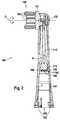
- Fig. 1is a perspective depiction of an example embodiment of a personal hygiene device 1, here realized as an electric toothbrush.
- the personal hygiene device 1comprises a handle 200 and a personal hygiene implement 100.
- the personal hygiene implement 100is realized as a replacement brush.
- the personal hygiene implement 100has a functional element 130, here realized as a brush head, which functional element 130 is movably mounted at a housing 150 of the personal hygiene implement 100 such that the functional element 130 can be driven into a motion, e.g. an oscillatory rotation (as indicated with double arrow 21) around a rotation axis R that may be perpendicular to the longitudinal axis L of the personal hygiene implement 100.
- a motione.g. an oscillatory rotation (as indicated with double arrow 21) around a rotation axis R that may be perpendicular to the longitudinal axis L of the personal hygiene implement 100.
- the personal hygiene devicemay be realized as an (electric) tongue scraper, an (electric) flossing device, an (electric) interdental cleaner, a massaging device etc.
- the personal hygiene implementmay then accordingly be realized as a tongue scraper section, a flossing section, an interdental cleaning section, a massaging section etc.
- the functional elementmay then accordingly be realized as a tongue scraper head, a flossing head, an interdental cleaning head, a massaging head etc.
- Fig. 2is a lateral cross sectional cut through an example embodiment of a personal hygiene implement 100 taken along a longitudinal axis of the personal hygiene implement 100.
- the personal hygiene implement 100comprises a housing 150 and a functional element 130, which is movably supported at the housing 150.
- the functional element 130may comprise a carrier element 131 on which a plurality of cleaning elements 133 may be mounted for cleaning and massaging parts of the oral cavity such as teeth and gums.
- the carrier element 131may be supported at the housing 150 by a mounting axle 132 for driven oscillatory rotation around a rotation axis R that in some embodiments is essentially perpendicular to the longitudinal axis (reference numeral L in Fig. 1 ) of the personal hygiene implement 100.
- other movementsare realized, e.g. an oscillatory rotation around a rotation axis essentially coinciding with or being essentially parallel to the longitudinal axis L.
- the personal hygiene implement 100further comprises a motion transmitter element 110 that in the shown embodiment is disposed within a cavity 159 formed within the implement housing 150.
- the motion transmitter element 110is functionally connected with the functional element 130 as will be explained in more detail with reference to Fig. 3 .
- “functionally connected”shall mean a connection that is not intended to be disconnected and that shall enable that motion transmitted via the motion transmitter element is transferred to the functional element.
- the motion transmitter element 110is arranged for transmission of a linear oscillatory movement to the functional element 130, which linear oscillatory motion may be generally parallel to the longitudinal axis of the personal hygiene implement 100 (as indicated by double arrow A).
- Such a linear oscillatory motionmay be provided by a drive shaft of a handle when the personal hygiene implement 100 is in an attached state, as will be explained in more detail with reference to Fig. 5 .
- the motion transmitter element 110has a first end 110A that is distal to the functional element 130.
- the motion transmitter element 110has a coupling side 119 on its first end 110A that is oriented towards the opening provided at the distal end of the personal hygiene implement 100.
- the coupling side 119may be flat and may essentially be lying in a plane perpendicular to the longitudinal axis. This shall not exclude that the coupling side may have any other form and may not be flat at all (and that it may in particular be a negative of the coupling side provided by the drive shaft of the handle to which the personal hygiene implement shall be attached).
- the coupling side 119may be retracted from the opening at the end of the housing intended for coupling with a handle section so that the adhesive connection is established at a longitudinal position inside of the housing 150, in particular where this longitudinal location is retracted by a value lying in the range of between about 0.5 cm to about 5.0 cm, e.g. 1.0 cm, 1.5 cm, 2.0 cm, 2.5 cm, 3.0 cm, 3.5 cm, 4.0 cm, 4.5 cm or any other value lying in the mentioned range from the end of the attachment housing and the length of the housing 150 may be in the range of between about 3.0 cm to about 10.0 cm.
- an adhesive layer 180is provided on the coupling side 119 of the motion transmitter element.
- the adhesive layer 180has a connection side 189 intended for getting into contact with a coupling side 219 of a drive shaft 210 of a handle 200 during an attachment procedure (see Fig. 4 for a depiction of an example embodiment of the handle) and for establishing an adhesive connection between the motion transmitter element 110 and the drive shaft.
- the adhesive layer 180may have a protection foil (provided for being peeled away) on its coupling side 189 to avoid drying-out of the adhesive prior to the attachment process, i.e. the protection foil would be peeled away just shortly before the attachment process.
- the adhesive layermay be chosen such that the adhesive force with respect to the material of the motion transmitter element is higher than the adhesive force with respect to the material of the drive shaft to which adhesive coupling is intended.
- the adhesive layermay thus comprise two different adhesive components in a double-layer arrangement or the different materials of motion transmitter element and drive shaft may be chosen respectively. When being separated, the adhesive layer would stay on the motion transmitter element instead of remaining on the drive shaft.
- the coupling side 119 of the motion transmitter element 110may at least partly be made from a plastic material or from a metal such as stainless steel.
- Fig. 2shows the adhesive layer 180 already being provided on the first end 110A of the motion transmitter element 110
- the personal hygiene implement and the adhesivemay be provided to a consumer by means of a kit comprising at least one personal hygiene implement and at least one packaged adhesive, e.g. a tube with liquid or viscous glue such as an acrylate resin or at least one piece of double-sided adhesive tape or strip with its two adhesive sides being protected by a peelable protection foil.
- the adhesive tape or stripmay already be provided in a pre-cut form.
- a consumermay then apply the adhesive onto the coupling side of the motion transmitter element of the personal hygiene implement and/or the coupling side of the drive shaft of the handle of the personal hygiene device in order to form the adhesive layer.
- two different adhesivesare provided, one for being applied onto the coupling side of the personal hygiene implement and one for being applied onto the coupling side of the drive shaft.
- the two different adhesivesmay be chosen as two components of a two-component adhesive.
- the coupling side 119 provided at the first end of the motion transmitter elementmay have an area in the range of between about 1 mm 2 to about 100 mm 2 , in particular in a range of between about 5 mm 2 to about 40 mm 2 .
- the coupling side 119may be circular and may have a diameter in the range of between about 1 mm and about 12 mm; in particular the diameter may be in a range of between about 4 mm and 8 mm.
- the area and shape of the coupling side 119 of the motion transmitter elementmay be chosen to coincide with the area and shape of the coupling side of the drive shaft to which the adhesive connection is intended.
- the adhesive layer 180may have a thickness in a range of between about 0.01 mm to about 5.0 mm, in particular of between about 0.1 mm and about 2.0 mm.
- the adhesive layer 180may in particular have a soft core, which soft core may further in particular have resilient properties.
- a soft core of the adhesive layer 180may efficiently reduce noise during operation of the personal hygiene device.
- the soft corecan also balance linear motion provided by the shaft of a personal hygiene device even so an externally applied force (e.g. applied at the functional element) keeps the motion transmitter element in a locked position.
- the personal hygiene implement 100 as shown in Fig. 2may further comprise an insert element 151 that is snapped into the attachment housing 150 thereby forming part of the housing 150.
- the insert element 151may be equipped with a first coupling structure 152 intended for establishing a further coupling (i.e. a coupling different to the adhesive coupling) with a handle of a personal hygiene device in an attached state.
- the first coupling structure 152is realized by mechanical coupling means such as snap hooks or spring elements for clamping projections provided at the handle section.
- the first coupling structure 152may be realized by a magnetic coupling element.
- the longitudinal positions where the adhesive connection is established and where the further connection (e.g. mechanical connection) is establishedmay be separated along the longitudinal direction, in particular by a distance lying in a range of between about 0.5 cm and about 5.0 cm.
- Fig. 3is a transverse longitudinal cross-sectional cut through an example personal hygiene implement similar to the one shown in Fig. 2 , where the viewing direction is towards the cleaning elements.
- the motion transmitter element 310is coupled to the functional element by a coupling pin 311 provided at a second end 310B of the motion transmitter element 310.
- the coupling pin 311establishes a coupling with a coupling section 334 provided at the carrier element 331 at a position that is eccentric with respect to the rotation axis defined by the mounting axle 332.
- the motion transmitter element 310is driven into a linear oscillatory movement as indicated by double arrow A, then the carrier element 331 will be driven into an oscillatory rotation around its rotation axis.
- the motion transmitter element 310is associated with a return force element such as a biasing spring that biases the motion transmitter element into a defined rest position whenever the motion transmitter element is not being driven.
- a coupling element 318may be provided at the first end 310A of the motion transmitter element 310, which coupling element 318 provides a coupling side 319.
- the coupling side 319may be provided from a different material than the material of the motion transmitter element 310, which material may be chosen because of its suitability for establishing an adhesive coupling having a high tensile strength with the adhesive layer 380.
- the motion transmitter element 310may be made from metal such as brass
- the coupling element 318may be made from a different metal such as aluminum or stainless steel or the coupling element may be made from a plastic material.
- the adhesive layer 380is here realized as having three sub-layers 381, 382, and 383, where sub-layer 181 is the outer adhesive sub-layer providing a respective coupling side 389 for establishing an adhesive connection with a drive shaft of a handle of an oral hygiene device.
- the inner adhesive sub-layer 382connects the adhesive layer 380 with the coupling element 318.
- a centre sub-layer 383is here realized as a soft foam layer.
- Fig. 4shows a longitudinal cut through a schematic handle 200.
- the handle 200comprises a drive shaft 210 that functions as a movable motor part of a resonant linear drive 260, which linear drive 260 is disposed within the handle housing 250.
- the linear driveis just an example and any other motor (and gear arrangement) providing a linear oscillatory motion may be provided.
- the linear drive 260provides for a linear oscillatory movement of the drive shaft 210 as is indicated by double arrow B.
- the drive shaft 210has a coupling side 219 intended for getting into contact with the respective coupling side 189, 389 (shown in Figures 2 and 3 ) of the adhesive layer 180, 380 (shown in Figures 2 and 3 ) of the personal hygiene implement when being attached.
- an adhesive layermay be provided on the coupling side 219 of the drive shaft 210.
- the handle sectionmay comprise a handle housing at which a second coupling structure intended for establishing a connection with the first coupling structure provided at the personal hygiene implement is realized.
- the handle section 200has a handle housing 250 comprising a top handle housing section 250A intended for coupling with the personal hygiene implement and a lower handle housing section 250B intended for being gripped by a user's hand.
- the top handle housing 250A sectioncomprises a top part 251 at which a second coupling structure 252 is realized.
- the second coupling structure 252can form a further connection with the first coupling structure 152 (shown in Fig. 2 ) of the personal hygiene implement.
- Fig. 5shows a longitudinal cross sectional cut of a personal hygiene implement 400 and a top housing section of a handle section 200 in an attached state. It is shown that the motion transmitter element 410 and the drive shaft 210 have established an adhesive connection via an adhesive layer 480 such that during operation, a linear reciprocation of the drive shaft 210 as indicated by double arrow B will be transferred to the functional element 430 via the motion transmitter element 410.
- the adhesive layer 480is here shown to comprise three sub-layers 481, 482, and 483 as had been explained in connection with Fig. 3 . But of course the adhesive layer 480 may be realized as a single layer of an adhesive material as discussed with reference to Fig. 2 .
- first and second coupling structures 152 and 252have established a further connection between the housing 150 of the personal hygiene implement and the handle housing 250 such that the personal hygiene implement 100 is fixed with respect to the handle housing 250.
Landscapes
- Health & Medical Sciences (AREA)
- Public Health (AREA)
- Epidemiology (AREA)
- Life Sciences & Earth Sciences (AREA)
- Animal Behavior & Ethology (AREA)
- General Health & Medical Sciences (AREA)
- Veterinary Medicine (AREA)
- Pain & Pain Management (AREA)
- Physical Education & Sports Medicine (AREA)
- Rehabilitation Therapy (AREA)
- Dentistry (AREA)
- Dermatology (AREA)
- Brushes (AREA)
Description
- The present invention is concerned with personal hygiene implements and in particular with personal hygiene implements having a movably mounted functional element that is coupled with a motion transmitter element.
US 2013/0060176 discloses a massaging device, in which the drive shaft is fixedly glued to a motion transmitter element.- It is known that for personal hygiene implements having a movably mounted functional element coupled with a motion transmitter element, the motion transmitter element may be functionally coupled with a drive shaft of a handle of a personal hygiene device by mechanical means (such as a snap-fit connection) or by magnetic means (e.g. a permanent magnet provided at the drive shaft couples with a magnetizable element provided at the motion transmitter element).
- While the mechanical connection may suffer from tolerances between the coupling partners inevitably leading to noise and wear, a magnetic connection may suffer from much higher costs for being realized.
- It is thus an object of the present disclosure to provide a personal hygiene implement and personal hygiene device that overcome the mentioned shortcomings of the known coupling means.
- In accordance with one aspect there is provided a personal hygiene implement in accordance with claim 1.
- In accordance with one aspect there is provided a personal hygiene device in accordance with claim 9.
- In accordance with one aspect there is provided a kit in accordance with claim 11.
- The present aspects will be further elucidated by a detailed discussion of general and specific example embodiments and with reference to figures. In the figures
- Fig. 1
- is a depiction of a personal hygiene device as proposed comprising a personal hygiene as proposed and a handle to which the personal hygiene implement is attached;
- Fig. 2
- is a longitudinal cross-sectional cut through an example personal hygiene implement;
- Fig. 3
- is a longitudinal cross-sectional cut through another example personal hygiene implement taken at a 90 degrees pivoted cut-plane in comparison to
Fig. 2 ; - Fig. 4
- is a longitudinal cross-sectional cut through a schematically shown handle of a personal hygiene device; and
- Fig. 5
- is a longitudinal cross-sectional cut to an upper portion of a personal hygiene device showing a personal hygiene implement being attached to a handle.
- In some embodiments, the adhesive layer of the proposed personal hygiene implement or the personal hygiene device is realized as a glue layer, i.e. a single layer of more or less homogeneously disposed glue. Alternatively, the adhesive layer may be realized by an adhesive tape or strip, in particular a double sided adhesive tape or strip. Alternatively or additionally, the adhesive layer may have two or even more sub-layers, in particular the adhesive layer may have a core layer made in particular from a non-adhesive material (e.g. a foam), and two adhesive layers on the outer opposite surfaces of the core layer. In some embodiments, the core layer has a soft core layer (e.g. a soft foam) that is elastically compressible under pressure such that it elastically extends back into its original state when the pressure is released (i.e. a resilient core).
- Instead of being realized at a motion transmitter element of a personal hygiene implement, the adhesive layer may be provided at a drive shaft of a handle of an personal hygiene device, where the drive shaft is intended to connect with a motion transmitter element of an personal hygiene implement. Alternatively, a kit may be provided comprising a personal hygiene implement as proposed, but without the adhesive layer, and an adhesive. The adhesive may be provided as packaged liquid or viscous glue or as a piece of an adhesive tape or strip.
- The adhesive layer may comprise a protective foil that can be peeled away just prior to attaching the personal hygiene implement onto the handle in order to avoid that the adhesive material is drying/curing before the attachment process or to avoid that dust or other stuff adheres to the adhesive layer.
- In some embodiments, the adhesive layer is chosen so that is provides a normal tensile strength of at least 0.15 N/mm2 and alternatively or additionally of not more than 0.7 N/mm2. Generally, all adhesive layers that provide a normal tensile strength between the motion transmitter element and the drive shaft of at least about 0.15 N/mm2 and of not more than 0.7 N/mm2 are considered as in particular suitable for connecting a motion transmitter element of a personal hygiene implement and a drive shaft of a handle of a personal hygiene device.
- "Normal tensile strength" of an adhesive bond in accordance with the present disclosure means the adhesive force required to separate two adhesively connected surfaces as defined by ASTM D897-08 "Standard Test Method for Tensile Properties of Adhesive Bonds".
- One example of a double sided adhesive tape is 3M™ VHB™ Acrylic Foam Tape 4943F that is characterized by a normal tensile strength (T-block) of 58.5 N/cm2 measured in accordance with ASTM D897-08 (after 72 hours of hardening time, to Aluminum at room temperature, 6.45 cm2, jaw speed of 50 mm/minute). All normal tensile strength values in the present disclosure are to be understood as being measured under the same conditions.
- Depending on the particular type of personal hygiene device, a minimum absolute tensile strength (the absolute tensile strength being determined by the normal tensile strength of the adhesive layer and the area over which is will be effective) provided between the motion transmitter element and the drive shaft should be 3 N, 3.5 N, 4 N, 4.5 N, 5 N, 5.5 N, 6 N, 6.5 N, 7 N, 7.5 N, 8 N, 8.5 N, or 9 N. For a personal hygiene device realized as an electric toothbrush with the personal hygiene implement realized as a replacement brush head with a functional element realized as a cleaning element carrier mounted for oscillatory rotation, a minimum absolute tensile strength in the range of about 6.0 N to about 7.0 N has been found to be a sensible choice to avoid that the adhesive connection is too often separated as reconnection between the coupling partners may then not happen automatically and/or not with the same absolute tensile strength of the original (i.e. first) adhesive connection or the adhesive coupling may not be reestablished at all, e.g. because the adhesive layer has lost its stickiness. Thus, instead of realizing the minimum absolute tensile strength between the motion transmitter element and the drive shaft, an absolute tensile strength of above 6 N or 7 N could be realized. Further, it had been found that the maximum tensile strength should not be above 40 N, potentially not above 30 N, and further it may be chosen to be not above about 20 N as otherwise the manual separation in case of a worn-out replacement brush may not be simply achievable by a user or the user may fear to break the replacement brush. Thus, for the example personal hygiene device realized as an electric toothbrush with the personal hygiene implement realized as a replacement brush head with a functional element realized as a cleaning element carrier mounted for oscillatory rotation, the absolute tensile strength should be in the range of between about 6 N to about 40 N, in particular between about 6 N to about 30 N, and even more particular in between about 6 N and about 20 N. In order to avoid repeated disconnection between the adhesive partners, the lower total tensile strength value may be chosen to be above about 6 N, in particular at least 7 N, 8 N, 9 N, 10 N, 11 N, 12 N, 13 N, 14 N, 15 N, 16 N, 17 N, 18 N, 19 N or about 20 N. Values between 10 N and 20 N may be preferred in order to avoid that the adhesive connection is unintentionally loosened or disconnected when an external force acts upon the functional element (e.g. keeps the functional element and thus the motion transmitter element in a locked position) while the drive of the personal hygiene device further tries to transfer a reciprocal linear motion via the motion transmitter element. The drive of the personal hygiene element may be realized such that it stops providing motion at an external force level already below the absolute tensile strength of the adhesive connection (e.g. the drive may stop at an external force of 10 N while the absolute tensile strength of the adhesive connection is 15 N).
- In some embodiments, the surface of the motion transmitter element and the drive shaft used for adhesive connection may be in the range of between 19 mm2 to 29 mm2 (e.g. the connection surface may be circular with a diameter of between about 5 mm to about 6 mm). The absolute tensile strength of such a connection using a respective circular piece of the before mentioned doubled sided 3M™ VHB™ Acrylic Foam Tape 4943F would then be in the range of about 11.5 N to about 16.5 N (assuming that the above given normal tensile strength of 0.585 N/mm2 would also be given between the motion transmitter element and the drive shaft).
- The aspects of the present disclosure are further discussed by reference to figures showing particular example embodiments. Where a feature is not necessarily mandatory and thus should not necessarily be understood as a necessary disclosure of connected essential features, this is made clear by referring to such a feature by a "may be" clause.
Fig. 1 is a perspective depiction of an example embodiment of a personal hygiene device 1, here realized as an electric toothbrush. The personal hygiene device 1 comprises ahandle 200 and a personal hygiene implement 100. Here, thepersonal hygiene implement 100 is realized as a replacement brush. Thepersonal hygiene implement 100 has afunctional element 130, here realized as a brush head, whichfunctional element 130 is movably mounted at ahousing 150 of the personal hygiene implement 100 such that thefunctional element 130 can be driven into a motion, e.g. an oscillatory rotation (as indicated with double arrow 21) around a rotation axis R that may be perpendicular to the longitudinal axis L of the personal hygiene implement 100. Instead of being realized as an electric toothbrush, the personal hygiene device may be realized as an (electric) tongue scraper, an (electric) flossing device, an (electric) interdental cleaner, a massaging device etc. The personal hygiene implement may then accordingly be realized as a tongue scraper section, a flossing section, an interdental cleaning section, a massaging section etc. The functional element may then accordingly be realized as a tongue scraper head, a flossing head, an interdental cleaning head, a massaging head etc.Fig. 2 is a lateral cross sectional cut through an example embodiment of a personal hygiene implement 100 taken along a longitudinal axis of the personal hygiene implement 100. Thepersonal hygiene implement 100 comprises ahousing 150 and afunctional element 130, which is movably supported at thehousing 150.- The
functional element 130 may comprise acarrier element 131 on which a plurality ofcleaning elements 133 may be mounted for cleaning and massaging parts of the oral cavity such as teeth and gums. Thecarrier element 131 may be supported at thehousing 150 by amounting axle 132 for driven oscillatory rotation around a rotation axis R that in some embodiments is essentially perpendicular to the longitudinal axis (reference numeral L inFig. 1 ) of the personal hygiene implement 100. In some embodiments, other movements are realized, e.g. an oscillatory rotation around a rotation axis essentially coinciding with or being essentially parallel to the longitudinal axis L. - The personal hygiene implement 100 further comprises a
motion transmitter element 110 that in the shown embodiment is disposed within acavity 159 formed within theimplement housing 150. Themotion transmitter element 110 is functionally connected with thefunctional element 130 as will be explained in more detail with reference toFig. 3 . Generally and applicable to all embodiments, "functionally connected" shall mean a connection that is not intended to be disconnected and that shall enable that motion transmitted via the motion transmitter element is transferred to the functional element. Themotion transmitter element 110 is arranged for transmission of a linear oscillatory movement to thefunctional element 130, which linear oscillatory motion may be generally parallel to the longitudinal axis of the personal hygiene implement 100 (as indicated by double arrow A). Such a linear oscillatory motion may be provided by a drive shaft of a handle when the personal hygiene implement 100 is in an attached state, as will be explained in more detail with reference toFig. 5 . - The
motion transmitter element 110 has afirst end 110A that is distal to thefunctional element 130. Themotion transmitter element 110 has acoupling side 119 on itsfirst end 110A that is oriented towards the opening provided at the distal end of the personal hygiene implement 100. Thecoupling side 119 may be flat and may essentially be lying in a plane perpendicular to the longitudinal axis. This shall not exclude that the coupling side may have any other form and may not be flat at all (and that it may in particular be a negative of the coupling side provided by the drive shaft of the handle to which the personal hygiene implement shall be attached). Generally and applicable to all embodiments, thecoupling side 119 may be retracted from the opening at the end of the housing intended for coupling with a handle section so that the adhesive connection is established at a longitudinal position inside of thehousing 150, in particular where this longitudinal location is retracted by a value lying in the range of between about 0.5 cm to about 5.0 cm, e.g. 1.0 cm, 1.5 cm, 2.0 cm, 2.5 cm, 3.0 cm, 3.5 cm, 4.0 cm, 4.5 cm or any other value lying in the mentioned range from the end of the attachment housing and the length of thehousing 150 may be in the range of between about 3.0 cm to about 10.0 cm. - In some embodiments, as shown in
Fig. 2 , anadhesive layer 180 is provided on thecoupling side 119 of the motion transmitter element. Theadhesive layer 180 has aconnection side 189 intended for getting into contact with acoupling side 219 of adrive shaft 210 of ahandle 200 during an attachment procedure (seeFig. 4 for a depiction of an example embodiment of the handle) and for establishing an adhesive connection between themotion transmitter element 110 and the drive shaft. Theadhesive layer 180 may have a protection foil (provided for being peeled away) on itscoupling side 189 to avoid drying-out of the adhesive prior to the attachment process, i.e. the protection foil would be peeled away just shortly before the attachment process. Additionally or alternatively, the adhesive layer may be chosen such that the adhesive force with respect to the material of the motion transmitter element is higher than the adhesive force with respect to the material of the drive shaft to which adhesive coupling is intended. The adhesive layer may thus comprise two different adhesive components in a double-layer arrangement or the different materials of motion transmitter element and drive shaft may be chosen respectively. When being separated, the adhesive layer would stay on the motion transmitter element instead of remaining on the drive shaft. Thecoupling side 119 of themotion transmitter element 110 may at least partly be made from a plastic material or from a metal such as stainless steel. - While
Fig. 2 shows theadhesive layer 180 already being provided on thefirst end 110A of themotion transmitter element 110, the personal hygiene implement and the adhesive may be provided to a consumer by means of a kit comprising at least one personal hygiene implement and at least one packaged adhesive, e.g. a tube with liquid or viscous glue such as an acrylate resin or at least one piece of double-sided adhesive tape or strip with its two adhesive sides being protected by a peelable protection foil. The adhesive tape or strip may already be provided in a pre-cut form. A consumer may then apply the adhesive onto the coupling side of the motion transmitter element of the personal hygiene implement and/or the coupling side of the drive shaft of the handle of the personal hygiene device in order to form the adhesive layer. In some embodiments, two different adhesives are provided, one for being applied onto the coupling side of the personal hygiene implement and one for being applied onto the coupling side of the drive shaft. The two different adhesives may be chosen as two components of a two-component adhesive. - The
coupling side 119 provided at the first end of the motion transmitter element may have an area in the range of between about 1 mm2 to about 100 mm2, in particular in a range of between about 5 mm2 to about 40 mm2. Thecoupling side 119 may be circular and may have a diameter in the range of between about 1 mm and about 12 mm; in particular the diameter may be in a range of between about 4 mm and 8 mm. The area and shape of thecoupling side 119 of the motion transmitter element may be chosen to coincide with the area and shape of the coupling side of the drive shaft to which the adhesive connection is intended. - The
adhesive layer 180 may have a thickness in a range of between about 0.01 mm to about 5.0 mm, in particular of between about 0.1 mm and about 2.0 mm. Theadhesive layer 180 may in particular have a soft core, which soft core may further in particular have resilient properties. A soft core of theadhesive layer 180 may efficiently reduce noise during operation of the personal hygiene device. The soft core can also balance linear motion provided by the shaft of a personal hygiene device even so an externally applied force (e.g. applied at the functional element) keeps the motion transmitter element in a locked position. - The personal hygiene implement 100 as shown in
Fig. 2 may further comprise aninsert element 151 that is snapped into theattachment housing 150 thereby forming part of thehousing 150. Theinsert element 151 may be equipped with afirst coupling structure 152 intended for establishing a further coupling (i.e. a coupling different to the adhesive coupling) with a handle of a personal hygiene device in an attached state. In the shown example embodiment, thefirst coupling structure 152 is realized by mechanical coupling means such as snap hooks or spring elements for clamping projections provided at the handle section. In other example embodiments, thefirst coupling structure 152 may be realized by a magnetic coupling element. The longitudinal positions where the adhesive connection is established and where the further connection (e.g. mechanical connection) is established may be separated along the longitudinal direction, in particular by a distance lying in a range of between about 0.5 cm and about 5.0 cm. Fig. 3 is a transverse longitudinal cross-sectional cut through an example personal hygiene implement similar to the one shown inFig. 2 , where the viewing direction is towards the cleaning elements. As can be seen fromFig. 3 , themotion transmitter element 310 is coupled to the functional element by acoupling pin 311 provided at asecond end 310B of themotion transmitter element 310. Thecoupling pin 311 establishes a coupling with acoupling section 334 provided at thecarrier element 331 at a position that is eccentric with respect to the rotation axis defined by the mountingaxle 332. When themotion transmitter element 310 is driven into a linear oscillatory movement as indicated by double arrow A, then thecarrier element 331 will be driven into an oscillatory rotation around its rotation axis. In some embodiments, themotion transmitter element 310 is associated with a return force element such as a biasing spring that biases the motion transmitter element into a defined rest position whenever the motion transmitter element is not being driven. InFig. 3 it is shown, that acoupling element 318 may be provided at thefirst end 310A of themotion transmitter element 310, whichcoupling element 318 provides acoupling side 319. By such acoupling element 318, thecoupling side 319 may be provided from a different material than the material of themotion transmitter element 310, which material may be chosen because of its suitability for establishing an adhesive coupling having a high tensile strength with theadhesive layer 380. While themotion transmitter element 310 may be made from metal such as brass, thecoupling element 318 may be made from a different metal such as aluminum or stainless steel or the coupling element may be made from a plastic material.- The
adhesive layer 380 is here realized as having threesub-layers respective coupling side 389 for establishing an adhesive connection with a drive shaft of a handle of an oral hygiene device. The inneradhesive sub-layer 382 connects theadhesive layer 380 with thecoupling element 318. Acentre sub-layer 383 is here realized as a soft foam layer. Fig. 4 shows a longitudinal cut through aschematic handle 200. In the shown example embodiment, thehandle 200 comprises adrive shaft 210 that functions as a movable motor part of a resonantlinear drive 260, whichlinear drive 260 is disposed within thehandle housing 250. Obviously, the linear drive is just an example and any other motor (and gear arrangement) providing a linear oscillatory motion may be provided. During operation, thelinear drive 260 provides for a linear oscillatory movement of thedrive shaft 210 as is indicated by double arrow B. Thedrive shaft 210 has acoupling side 219 intended for getting into contact with therespective coupling side 189, 389 (shown inFigures 2 and3 ) of theadhesive layer 180, 380 (shown inFigures 2 and3 ) of the personal hygiene implement when being attached. Alternatively or additionally, an adhesive layer may be provided on thecoupling side 219 of thedrive shaft 210.- The handle section may comprise a handle housing at which a second coupling structure intended for establishing a connection with the first coupling structure provided at the personal hygiene implement is realized. In the shown example embodiment, the
handle section 200 has ahandle housing 250 comprising a tophandle housing section 250A intended for coupling with the personal hygiene implement and a lowerhandle housing section 250B intended for being gripped by a user's hand. Here, thetop handle housing 250A section comprises atop part 251 at which asecond coupling structure 252 is realized. Thesecond coupling structure 252 can form a further connection with the first coupling structure 152 (shown inFig. 2 ) of the personal hygiene implement. Fig. 5 shows a longitudinal cross sectional cut of a personal hygiene implement 400 and a top housing section of ahandle section 200 in an attached state. It is shown that themotion transmitter element 410 and thedrive shaft 210 have established an adhesive connection via anadhesive layer 480 such that during operation, a linear reciprocation of thedrive shaft 210 as indicated by double arrow B will be transferred to thefunctional element 430 via themotion transmitter element 410.- The
adhesive layer 480 is here shown to comprise threesub-layers Fig. 3 . But of course theadhesive layer 480 may be realized as a single layer of an adhesive material as discussed with reference toFig. 2 . - Further, the first and
second coupling structures housing 150 of the personal hygiene implement and thehandle housing 250 such that the personal hygiene implement 100 is fixed with respect to thehandle housing 250. - In order to attach a personal hygiene implement as proposed with a handle of a personal hygiene device, the following steps may be performed:
- 1. Providing a personal hygiene implement as proposed either with a readily prepared adhesive layer (which may involve peeling away a protective foil provided over the adhesive layer) or applying an adhesive layer to a coupling side of a motion transmitter element, e.g. by gluing a double-sided adhesive tape onto the coupling side or by distributing a drop of liquid adhesive material onto the coupling side.
- 2. Providing a handle of an personal hygiene device suitable for attaching the personal hygiene implement onto it, which in particular implies that a shaft for providing a linear reciprocating motion is present, which shaft has a coupling side intended for being adhesively coupled with the adhesive layer provided at the coupling side of the motion transmitter element (where this step may additionally involve providing a shaft having a coupling side equipped with an adhesive layer or applying an adhesive layer onto the coupling side of the shaft - the adhesive layer may comprise an adhesive material representing one component of a two-component glue and the adhesive layer on the motion transmitter element may then comprise an adhesive material representing the second component of the two-component adhesive).
- 3. Moving the motion transmitter element into a position where it is in its most elongated state (i.e. where the coupling side is at a position most distal to the functional head of the personal hygiene implement) e.g. by manually moving the functional element to which the motion transmitter element is coupled into a position associated with this most distal position of the coupling side of the motion transmitter element.
- 4. Attaching the personal hygiene implement and the handle such that the coupling sides of the motion transmitter element and the shaft come into pressurized contact.
- 5. Holding this position for a period allowing the adhesive connection to establish.
- 6. Releasing the motion transmitter element from the elongated state.
- The dimensions and values disclosed herein are not to be understood as being strictly limited to the exact numerical values recited. Instead, unless otherwise specified, each such dimension is intended to mean both the recited value and a functionally equivalent range surrounding that value. For example, a dimension disclosed as "40 mm" is intended to mean "about 40 mm."
Claims (11)
- A personal hygiene implement (100) attachable to a handle (200) of a personal hygiene device (1), wherein the personal hygiene device is one of an electric toothbrush, an electric tongue scraper, an electric flossing device, an electric interdental cleaner, or a massaging device and the personal hygiene implement is a respective replacement brush, tongue scraper head, flossing head, interdental cleaning head, or massaging head, comprising:a housing (150);a functional element (130) movably mounted at the housing such that it can be driven into a motion;a motion transmitter element (110; 310) coupled with the functional element;an adhesive layer (180; 380) provided at the motion transmitter element for adhesively coupling the motion transmitter element with a drive shaft (210) of the handle when being attached,wherein the adhesive layer is chosen such that the adhesive connection established after attachment is essentially non-destructively separable.
- The personal hygiene implement in accordance with claim 1, wherein the adhesive layer (180). is realized by a glue layer.
- The personal hygiene implement in accordance with claim 1, wherein the adhesive layer (380) is realized by an adhesive tape or strip, in particular a double-sided adhesive tape or strip.
- The personal hygiene implement in accordance with any one of claims 1 to 3, wherein the adhesive layer has at least one soft core (383).
- The personal hygiene implement in accordance with any one of claims 1 to 4, wherein the adhesive layer has a normal tensile strength of at least 0.15 N/mm2.
- The personal hygiene implement in accordance with any one of claims 1 to 5, wherein the adhesive layer has a normal tensile strength of below 0.7 N/mm2.
- The personal hygiene implement in accordance with any one of claims 1 to 6, wherein at least a part (318) of the section of the motion transmitter element (310) at which the adhesive layer is arranged is made from metal such as stainless steel or aluminum.
- The personal hygiene implement in accordance with any one of claims 1 to 6, wherein at least a part of the section of the motion transmitter element at which the adhesive layer is arranged is made from a plastic material.
- A personal hygiene device (1) being one of an electric toothbrush, an electric tongue scraper, an electric flossing device, an electric interdental cleaner comprising:a handle (200) comprisinga housing (250); anda drive shaft (210) coupled to a drive (260);a personal hygiene implement (400) being a respective replacement brush, tongue scraper head, flossing head, interdental cleaning head, or massaging head connected with the handle, comprisinga housing (450);a functional element (430) movably mounted at the housing such that it can be driven into a motion; anda motion transmitter element (410) coupled with the functional element; andan adhesive layer (480) connecting the drive shaft with the motion transmitter element in an essentially non-destructively separable manner.
- The personal hygiene device in accordance with the previous claim, wherein the adhesive layer has a higher adhesion force with respect to the motion transmitter element than with respect to the drive shaft.
- A kit comprising:at least one personal hygiene implement (100) being a replacement brush, tongue scraper head, flossing head, interdental cleaning head, or massaging head comprising a housing (150), a functional element (130) movably mounted at the housing such that it can be driven into a motion, and a motion transmitter element (110) coupled with the functional element; andan adhesive, in particular a packaged fluid or viscous adhesive and/or at least one piece of an adhesive tape or strip for connecting a drive shaft of a personal hygiene device with the motion transmitter element in an essentially non-destructively separable manner.
Priority Applications (7)
| Application Number | Priority Date | Filing Date | Title |
|---|---|---|---|
| ES13174662.0TES2608332T3 (en) | 2013-07-02 | 2013-07-02 | Personal hygiene tool and personal hygiene device |
| EP13174662.0AEP2821029B1 (en) | 2013-07-02 | 2013-07-02 | Personal hygiene implement and personal hygiene device |
| JP2016522923AJP6385432B2 (en) | 2013-07-02 | 2014-06-23 | Oral hygiene tool and oral hygiene device |
| CN201480037658.8ACN105377182B (en) | 2013-07-02 | 2014-06-23 | Oral hygiene implements and oral hygiene device |
| PCT/IB2014/062546WO2015001447A1 (en) | 2013-07-02 | 2014-06-23 | Oral hygiene implement and oral hygiene device |
| CA2917141ACA2917141A1 (en) | 2013-07-02 | 2014-06-23 | Oral hygiene implement and oral hygiene device |
| US14/314,414US9358088B2 (en) | 2013-07-02 | 2014-06-25 | Oral hygiene implement and oral hygiene device |
Applications Claiming Priority (1)
| Application Number | Priority Date | Filing Date | Title |
|---|---|---|---|
| EP13174662.0AEP2821029B1 (en) | 2013-07-02 | 2013-07-02 | Personal hygiene implement and personal hygiene device |
Publications (2)
| Publication Number | Publication Date |
|---|---|
| EP2821029A1 EP2821029A1 (en) | 2015-01-07 |
| EP2821029B1true EP2821029B1 (en) | 2016-10-12 |
Family
ID=48745772
Family Applications (1)
| Application Number | Title | Priority Date | Filing Date |
|---|---|---|---|
| EP13174662.0AActiveEP2821029B1 (en) | 2013-07-02 | 2013-07-02 | Personal hygiene implement and personal hygiene device |
Country Status (7)
| Country | Link |
|---|---|
| US (1) | US9358088B2 (en) |
| EP (1) | EP2821029B1 (en) |
| JP (1) | JP6385432B2 (en) |
| CN (1) | CN105377182B (en) |
| CA (1) | CA2917141A1 (en) |
| ES (1) | ES2608332T3 (en) |
| WO (1) | WO2015001447A1 (en) |
Cited By (1)
| Publication number | Priority date | Publication date | Assignee | Title |
|---|---|---|---|---|
| EP4582052A3 (en)* | 2022-01-31 | 2025-09-24 | Braun GmbH | Attachment for an oral care device handle |
Families Citing this family (9)
| Publication number | Priority date | Publication date | Assignee | Title |
|---|---|---|---|---|
| USD773192S1 (en)* | 2015-01-09 | 2016-12-06 | Ranir, Llc | Powered toothbrush handle |
| US10412099B2 (en)* | 2016-06-22 | 2019-09-10 | Paypal, Inc. | System security configurations based on assets associated with activities |
| USD831358S1 (en)* | 2016-12-13 | 2018-10-23 | Braun Gmbh | Toothbrush head |
| CN110545753B (en)* | 2017-04-24 | 2022-01-18 | 太阳星光齿磨公司 | Electric tooth brush |
| GB2575024B (en)* | 2018-06-20 | 2021-09-29 | Dyson Technology Ltd | Dental treatment appliance |
| USD972302S1 (en) | 2020-03-13 | 2022-12-13 | Ranir, Llc | Toothbrush drive unit |
| EP4050237B1 (en)* | 2021-02-24 | 2024-07-03 | Braun GmbH | Drive unit and personal care device with a drive unit |
| WO2025062250A1 (en)* | 2023-09-21 | 2025-03-27 | Braun Gmbh | Coupling section for personal-care implement and process of making same, including tolerance compensation |
| WO2025062249A1 (en)* | 2023-09-21 | 2025-03-27 | Braun Gmbh | Coupling section for personal-care implement and process of making same, including tolerance compensation |
Family Cites Families (13)
| Publication number | Priority date | Publication date | Assignee | Title |
|---|---|---|---|---|
| JPS4955268U (en)* | 1972-08-18 | 1974-05-16 | ||
| DE4438732A1 (en)* | 1994-10-29 | 1996-05-02 | Braun Ag | Brush part for an electric toothbrush |
| CN2496419Y (en)* | 2001-07-06 | 2002-06-26 | 吴迪 | Electric tooth-brushing machine |
| CN2561266Y (en)* | 2002-08-27 | 2003-07-23 | 杨佳恒 | Telescopic tooth-brush |
| WO2004093719A2 (en)* | 2003-04-23 | 2004-11-04 | The Procter & Gamble Company | Electric toothbrushes |
| JP4400464B2 (en)* | 2005-01-19 | 2010-01-20 | パナソニック電工株式会社 | Vibration and rolling linear actuator and electric toothbrush using the same |
| US20090007357A1 (en)* | 2007-05-07 | 2009-01-08 | The Gillette Company | Oral Hygiene Implements |
| US8985883B2 (en)* | 2007-07-30 | 2015-03-24 | The Procter & Gamble Company | Control surfaces for applicator with moveable applicator head |
| US20120010049A1 (en)* | 2009-03-25 | 2012-01-12 | Amalaha Leonard D | Device for an Automatic Body Fat Reducing and Muscle Building |
| JP5662866B2 (en)* | 2011-03-31 | 2015-02-04 | 積水化学工業株式会社 | Adhesive sheet |
| US9579250B2 (en)* | 2011-06-30 | 2017-02-28 | Thomas Nichols | Handheld motorized facial brush having pivoting, floating head |
| PL2550938T3 (en)* | 2011-07-25 | 2015-06-30 | Braun Gmbh | Oral hygiene device |
| ES2451021T3 (en)* | 2011-07-25 | 2014-03-26 | Braun Gmbh | Magnetic connection between a toothbrush handle and a brush head |
- 2013
- 2013-07-02EPEP13174662.0Apatent/EP2821029B1/enactiveActive
- 2013-07-02ESES13174662.0Tpatent/ES2608332T3/enactiveActive
- 2014
- 2014-06-23CNCN201480037658.8Apatent/CN105377182B/enactiveActive
- 2014-06-23WOPCT/IB2014/062546patent/WO2015001447A1/enactiveApplication Filing
- 2014-06-23JPJP2016522923Apatent/JP6385432B2/enactiveActive
- 2014-06-23CACA2917141Apatent/CA2917141A1/ennot_activeAbandoned
- 2014-06-25USUS14/314,414patent/US9358088B2/enactiveActive
Cited By (1)
| Publication number | Priority date | Publication date | Assignee | Title |
|---|---|---|---|---|
| EP4582052A3 (en)* | 2022-01-31 | 2025-09-24 | Braun GmbH | Attachment for an oral care device handle |
Also Published As
| Publication number | Publication date |
|---|---|
| WO2015001447A1 (en) | 2015-01-08 |
| US9358088B2 (en) | 2016-06-07 |
| CN105377182B (en) | 2017-12-19 |
| CN105377182A (en) | 2016-03-02 |
| JP6385432B2 (en) | 2018-09-05 |
| CA2917141A1 (en) | 2015-01-08 |
| ES2608332T3 (en) | 2017-04-07 |
| US20150007398A1 (en) | 2015-01-08 |
| JP2016523166A (en) | 2016-08-08 |
| EP2821029A1 (en) | 2015-01-07 |
Similar Documents
| Publication | Publication Date | Title |
|---|---|---|
| EP2821029B1 (en) | Personal hygiene implement and personal hygiene device | |
| JP6549188B2 (en) | Attachment section for oral hygiene devices | |
| KR101560105B1 (en) | Oral cleaning tool for an oral hygiene device | |
| WO2021207751A1 (en) | Handle for an electrically operated personal care implement and personal care implement | |
| JP5734849B2 (en) | Cutting tool with magnetically controlled preload | |
| EP1234637A3 (en) | Torque driver for interference screw | |
| CA2403134A1 (en) | Oral irrigator and brush assembly | |
| CA2358351A1 (en) | Disposable glove | |
| WO2007116292A8 (en) | Dermabrasion handpiece | |
| WO2004081299A3 (en) | Disposable plunger construction | |
| CA2544206C (en) | Ultrasonic insert with soft grip and method | |
| WO2004030728A3 (en) | Needle insertion device | |
| US11918101B2 (en) | Connecting structure for electric cleaning device handle and head assembly | |
| EP2377422A3 (en) | Power toothbrush with unique handle | |
| EP2075184A3 (en) | Handlebar tape | |
| US20110183148A1 (en) | Reversible adhesive bonding system | |
| US20090111070A1 (en) | Ultrasonic insert with soft grip and method | |
| JP2003167076A (en) | Method and tool for attaching and detaching back lid of clock | |
| HK1194650B (en) | Oral cleaning tool for an oral hygiene device | |
| JPH07298448A (en) | Connection structure of protector for harness protection |
Legal Events
| Date | Code | Title | Description |
|---|---|---|---|
| PUAI | Public reference made under article 153(3) epc to a published international application that has entered the european phase | Free format text:ORIGINAL CODE: 0009012 | |
| 17P | Request for examination filed | Effective date:20130702 | |
| AK | Designated contracting states | Kind code of ref document:A1 Designated state(s):AL AT BE BG CH CY CZ DE DK EE ES FI FR GB GR HR HU IE IS IT LI LT LU LV MC MK MT NL NO PL PT RO RS SE SI SK SM TR | |
| AX | Request for extension of the european patent | Extension state:BA ME | |
| R17P | Request for examination filed (corrected) | Effective date:20150619 | |
| RBV | Designated contracting states (corrected) | Designated state(s):AL AT BE BG CH CY CZ DE DK EE ES FI FR GB GR HR HU IE IS IT LI LT LU LV MC MK MT NL NO PL PT RO RS SE SI SK SM TR | |
| 17Q | First examination report despatched | Effective date:20160216 | |
| GRAP | Despatch of communication of intention to grant a patent | Free format text:ORIGINAL CODE: EPIDOSNIGR1 | |
| RIC1 | Information provided on ipc code assigned before grant | Ipc:A61H 7/00 20060101ALI20160419BHEP Ipc:A61H 13/00 20060101ALI20160419BHEP Ipc:A61C 17/22 20060101AFI20160419BHEP Ipc:A61C 1/18 20060101ALN20160419BHEP Ipc:A61H 23/02 20060101ALI20160419BHEP | |
| INTG | Intention to grant announced | Effective date:20160512 | |
| GRAS | Grant fee paid | Free format text:ORIGINAL CODE: EPIDOSNIGR3 | |
| GRAA | (expected) grant | Free format text:ORIGINAL CODE: 0009210 | |
| AK | Designated contracting states | Kind code of ref document:B1 Designated state(s):AL AT BE BG CH CY CZ DE DK EE ES FI FR GB GR HR HU IE IS IT LI LT LU LV MC MK MT NL NO PL PT RO RS SE SI SK SM TR | |
| REG | Reference to a national code | Ref country code:GB Ref legal event code:FG4D | |
| REG | Reference to a national code | Ref country code:CH Ref legal event code:EP | |
| REG | Reference to a national code | Ref country code:AT Ref legal event code:REF Ref document number:835751 Country of ref document:AT Kind code of ref document:T Effective date:20161015 | |
| REG | Reference to a national code | Ref country code:IE Ref legal event code:FG4D | |
| REG | Reference to a national code | Ref country code:DE Ref legal event code:R096 Ref document number:602013012640 Country of ref document:DE | |
| REG | Reference to a national code | Ref country code:NL Ref legal event code:FP | |
| REG | Reference to a national code | Ref country code:SE Ref legal event code:TRGR | |
| REG | Reference to a national code | Ref country code:LT Ref legal event code:MG4D | |
| PG25 | Lapsed in a contracting state [announced via postgrant information from national office to epo] | Ref country code:LV Free format text:LAPSE BECAUSE OF FAILURE TO SUBMIT A TRANSLATION OF THE DESCRIPTION OR TO PAY THE FEE WITHIN THE PRESCRIBED TIME-LIMIT Effective date:20161012 | |
| REG | Reference to a national code | Ref country code:AT Ref legal event code:MK05 Ref document number:835751 Country of ref document:AT Kind code of ref document:T Effective date:20161012 | |
| REG | Reference to a national code | Ref country code:ES Ref legal event code:FG2A Ref document number:2608332 Country of ref document:ES Kind code of ref document:T3 Effective date:20170407 | |
| PG25 | Lapsed in a contracting state [announced via postgrant information from national office to epo] | Ref country code:NO Free format text:LAPSE BECAUSE OF FAILURE TO SUBMIT A TRANSLATION OF THE DESCRIPTION OR TO PAY THE FEE WITHIN THE PRESCRIBED TIME-LIMIT Effective date:20170112 Ref country code:LT Free format text:LAPSE BECAUSE OF FAILURE TO SUBMIT A TRANSLATION OF THE DESCRIPTION OR TO PAY THE FEE WITHIN THE PRESCRIBED TIME-LIMIT Effective date:20161012 Ref country code:GR Free format text:LAPSE BECAUSE OF FAILURE TO SUBMIT A TRANSLATION OF THE DESCRIPTION OR TO PAY THE FEE WITHIN THE PRESCRIBED TIME-LIMIT Effective date:20170113 | |
| PG25 | Lapsed in a contracting state [announced via postgrant information from national office to epo] | Ref country code:RS Free format text:LAPSE BECAUSE OF FAILURE TO SUBMIT A TRANSLATION OF THE DESCRIPTION OR TO PAY THE FEE WITHIN THE PRESCRIBED TIME-LIMIT Effective date:20161012 Ref country code:FI Free format text:LAPSE BECAUSE OF FAILURE TO SUBMIT A TRANSLATION OF THE DESCRIPTION OR TO PAY THE FEE WITHIN THE PRESCRIBED TIME-LIMIT Effective date:20161012 Ref country code:PL Free format text:LAPSE BECAUSE OF FAILURE TO SUBMIT A TRANSLATION OF THE DESCRIPTION OR TO PAY THE FEE WITHIN THE PRESCRIBED TIME-LIMIT Effective date:20161012 Ref country code:AT Free format text:LAPSE BECAUSE OF FAILURE TO SUBMIT A TRANSLATION OF THE DESCRIPTION OR TO PAY THE FEE WITHIN THE PRESCRIBED TIME-LIMIT Effective date:20161012 Ref country code:PT Free format text:LAPSE BECAUSE OF FAILURE TO SUBMIT A TRANSLATION OF THE DESCRIPTION OR TO PAY THE FEE WITHIN THE PRESCRIBED TIME-LIMIT Effective date:20170213 Ref country code:BE Free format text:LAPSE BECAUSE OF FAILURE TO SUBMIT A TRANSLATION OF THE DESCRIPTION OR TO PAY THE FEE WITHIN THE PRESCRIBED TIME-LIMIT Effective date:20161012 Ref country code:IS Free format text:LAPSE BECAUSE OF FAILURE TO SUBMIT A TRANSLATION OF THE DESCRIPTION OR TO PAY THE FEE WITHIN THE PRESCRIBED TIME-LIMIT Effective date:20170212 Ref country code:HR Free format text:LAPSE BECAUSE OF FAILURE TO SUBMIT A TRANSLATION OF THE DESCRIPTION OR TO PAY THE FEE WITHIN THE PRESCRIBED TIME-LIMIT Effective date:20161012 | |
| REG | Reference to a national code | Ref country code:FR Ref legal event code:PLFP Year of fee payment:5 | |
| REG | Reference to a national code | Ref country code:DE Ref legal event code:R097 Ref document number:602013012640 Country of ref document:DE | |
| PG25 | Lapsed in a contracting state [announced via postgrant information from national office to epo] | Ref country code:RO Free format text:LAPSE BECAUSE OF FAILURE TO SUBMIT A TRANSLATION OF THE DESCRIPTION OR TO PAY THE FEE WITHIN THE PRESCRIBED TIME-LIMIT Effective date:20161012 Ref country code:DK Free format text:LAPSE BECAUSE OF FAILURE TO SUBMIT A TRANSLATION OF THE DESCRIPTION OR TO PAY THE FEE WITHIN THE PRESCRIBED TIME-LIMIT Effective date:20161012 Ref country code:SK Free format text:LAPSE BECAUSE OF FAILURE TO SUBMIT A TRANSLATION OF THE DESCRIPTION OR TO PAY THE FEE WITHIN THE PRESCRIBED TIME-LIMIT Effective date:20161012 Ref country code:CZ Free format text:LAPSE BECAUSE OF FAILURE TO SUBMIT A TRANSLATION OF THE DESCRIPTION OR TO PAY THE FEE WITHIN THE PRESCRIBED TIME-LIMIT Effective date:20161012 Ref country code:EE Free format text:LAPSE BECAUSE OF FAILURE TO SUBMIT A TRANSLATION OF THE DESCRIPTION OR TO PAY THE FEE WITHIN THE PRESCRIBED TIME-LIMIT Effective date:20161012 | |
| PLBE | No opposition filed within time limit | Free format text:ORIGINAL CODE: 0009261 | |
| STAA | Information on the status of an ep patent application or granted ep patent | Free format text:STATUS: NO OPPOSITION FILED WITHIN TIME LIMIT | |
| PG25 | Lapsed in a contracting state [announced via postgrant information from national office to epo] | Ref country code:SM Free format text:LAPSE BECAUSE OF FAILURE TO SUBMIT A TRANSLATION OF THE DESCRIPTION OR TO PAY THE FEE WITHIN THE PRESCRIBED TIME-LIMIT Effective date:20161012 Ref country code:BG Free format text:LAPSE BECAUSE OF FAILURE TO SUBMIT A TRANSLATION OF THE DESCRIPTION OR TO PAY THE FEE WITHIN THE PRESCRIBED TIME-LIMIT Effective date:20170112 | |
| 26N | No opposition filed | Effective date:20170713 | |
| PG25 | Lapsed in a contracting state [announced via postgrant information from national office to epo] | Ref country code:SI Free format text:LAPSE BECAUSE OF FAILURE TO SUBMIT A TRANSLATION OF THE DESCRIPTION OR TO PAY THE FEE WITHIN THE PRESCRIBED TIME-LIMIT Effective date:20161012 | |
| REG | Reference to a national code | Ref country code:IE Ref legal event code:MM4A | |
| PG25 | Lapsed in a contracting state [announced via postgrant information from national office to epo] | Ref country code:IE Free format text:LAPSE BECAUSE OF NON-PAYMENT OF DUE FEES Effective date:20170702 | |
| REG | Reference to a national code | Ref country code:FR Ref legal event code:PLFP Year of fee payment:6 | |
| PG25 | Lapsed in a contracting state [announced via postgrant information from national office to epo] | Ref country code:LU Free format text:LAPSE BECAUSE OF NON-PAYMENT OF DUE FEES Effective date:20170702 | |
| PG25 | Lapsed in a contracting state [announced via postgrant information from national office to epo] | Ref country code:MT Free format text:LAPSE BECAUSE OF NON-PAYMENT OF DUE FEES Effective date:20170702 | |
| PG25 | Lapsed in a contracting state [announced via postgrant information from national office to epo] | Ref country code:MC Free format text:LAPSE BECAUSE OF FAILURE TO SUBMIT A TRANSLATION OF THE DESCRIPTION OR TO PAY THE FEE WITHIN THE PRESCRIBED TIME-LIMIT Effective date:20161012 Ref country code:HU Free format text:LAPSE BECAUSE OF FAILURE TO SUBMIT A TRANSLATION OF THE DESCRIPTION OR TO PAY THE FEE WITHIN THE PRESCRIBED TIME-LIMIT; INVALID AB INITIO Effective date:20130702 | |
| PG25 | Lapsed in a contracting state [announced via postgrant information from national office to epo] | Ref country code:CY Free format text:LAPSE BECAUSE OF FAILURE TO SUBMIT A TRANSLATION OF THE DESCRIPTION OR TO PAY THE FEE WITHIN THE PRESCRIBED TIME-LIMIT Effective date:20161012 | |
| PG25 | Lapsed in a contracting state [announced via postgrant information from national office to epo] | Ref country code:MK Free format text:LAPSE BECAUSE OF FAILURE TO SUBMIT A TRANSLATION OF THE DESCRIPTION OR TO PAY THE FEE WITHIN THE PRESCRIBED TIME-LIMIT Effective date:20161012 | |
| PG25 | Lapsed in a contracting state [announced via postgrant information from national office to epo] | Ref country code:TR Free format text:LAPSE BECAUSE OF FAILURE TO SUBMIT A TRANSLATION OF THE DESCRIPTION OR TO PAY THE FEE WITHIN THE PRESCRIBED TIME-LIMIT Effective date:20161012 | |
| PG25 | Lapsed in a contracting state [announced via postgrant information from national office to epo] | Ref country code:AL Free format text:LAPSE BECAUSE OF FAILURE TO SUBMIT A TRANSLATION OF THE DESCRIPTION OR TO PAY THE FEE WITHIN THE PRESCRIBED TIME-LIMIT Effective date:20161012 | |
| P01 | Opt-out of the competence of the unified patent court (upc) registered | Effective date:20230430 | |
| PGFP | Annual fee paid to national office [announced via postgrant information from national office to epo] | Ref country code:IT Payment date:20240612 Year of fee payment:12 | |
| PGFP | Annual fee paid to national office [announced via postgrant information from national office to epo] | Ref country code:DE Payment date:20240604 Year of fee payment:12 | |
| PGFP | Annual fee paid to national office [announced via postgrant information from national office to epo] | Ref country code:CH Payment date:20240801 Year of fee payment:12 | |
| PGFP | Annual fee paid to national office [announced via postgrant information from national office to epo] | Ref country code:GB Payment date:20250529 Year of fee payment:13 | |
| PGFP | Annual fee paid to national office [announced via postgrant information from national office to epo] | Ref country code:NL Payment date:20250613 Year of fee payment:13 | |
| PGFP | Annual fee paid to national office [announced via postgrant information from national office to epo] | Ref country code:FR Payment date:20250610 Year of fee payment:13 | |
| PGFP | Annual fee paid to national office [announced via postgrant information from national office to epo] | Ref country code:SE Payment date:20250610 Year of fee payment:13 | |
| PGFP | Annual fee paid to national office [announced via postgrant information from national office to epo] | Ref country code:ES Payment date:20250805 Year of fee payment:13 |