EP2819922B1 - Automated beverage dispensing system with cup lidding and method of placing a lid on a cup - Google Patents
Automated beverage dispensing system with cup lidding and method of placing a lid on a cupDownload PDFInfo
- Publication number
- EP2819922B1 EP2819922B1EP13708614.6AEP13708614AEP2819922B1EP 2819922 B1EP2819922 B1EP 2819922B1EP 13708614 AEP13708614 AEP 13708614AEP 2819922 B1EP2819922 B1EP 2819922B1
- Authority
- EP
- European Patent Office
- Prior art keywords
- lid
- cup
- lidding
- beverage dispenser
- beverage
- Prior art date
- Legal status (The legal status is an assumption and is not a legal conclusion. Google has not performed a legal analysis and makes no representation as to the accuracy of the status listed.)
- Active
Links
Images


Classifications
- G—PHYSICS
- G06—COMPUTING OR CALCULATING; COUNTING
- G06F—ELECTRIC DIGITAL DATA PROCESSING
- G06F13/00—Interconnection of, or transfer of information or other signals between, memories, input/output devices or central processing units
- G06F13/10—Program control for peripheral devices
- B—PERFORMING OPERATIONS; TRANSPORTING
- B65—CONVEYING; PACKING; STORING; HANDLING THIN OR FILAMENTARY MATERIAL
- B65B—MACHINES, APPARATUS OR DEVICES FOR, OR METHODS OF, PACKAGING ARTICLES OR MATERIALS; UNPACKING
- B65B7/00—Closing containers or receptacles after filling
- B65B7/16—Closing semi-rigid or rigid containers or receptacles not deformed by, or not taking-up shape of, contents, e.g. boxes or cartons
- B65B7/28—Closing semi-rigid or rigid containers or receptacles not deformed by, or not taking-up shape of, contents, e.g. boxes or cartons by applying separate preformed closures, e.g. lids, covers
- B65B7/2807—Feeding closures
- B—PERFORMING OPERATIONS; TRANSPORTING
- B67—OPENING, CLOSING OR CLEANING BOTTLES, JARS OR SIMILAR CONTAINERS; LIQUID HANDLING
- B67D—DISPENSING, DELIVERING OR TRANSFERRING LIQUIDS, NOT OTHERWISE PROVIDED FOR
- B67D1/00—Apparatus or devices for dispensing beverages on draught
- B67D1/08—Details
- B67D1/12—Flow or pressure control devices or systems, e.g. valves, gas pressure control, level control in storage containers
- B67D1/127—Froth control
- B67D1/1272—Froth control preventing froth
- G—PHYSICS
- G07—CHECKING-DEVICES
- G07F—COIN-FREED OR LIKE APPARATUS
- G07F13/00—Coin-freed apparatus for controlling dispensing or fluids, semiliquids or granular material from reservoirs
- G07F13/10—Coin-freed apparatus for controlling dispensing or fluids, semiliquids or granular material from reservoirs with associated dispensing of containers, e.g. cups or other articles
- B—PERFORMING OPERATIONS; TRANSPORTING
- B67—OPENING, CLOSING OR CLEANING BOTTLES, JARS OR SIMILAR CONTAINERS; LIQUID HANDLING
- B67D—DISPENSING, DELIVERING OR TRANSFERRING LIQUIDS, NOT OTHERWISE PROVIDED FOR
- B67D2210/00—Indexing scheme relating to aspects and details of apparatus or devices for dispensing beverages on draught or for controlling flow of liquids under gravity from storage containers for dispensing purposes
- B67D2210/00028—Constructional details
- B67D2210/00065—Constructional details related to the use of drinking cups or glasses
- B67D2210/00076—Cup conveyors
- B—PERFORMING OPERATIONS; TRANSPORTING
- B67—OPENING, CLOSING OR CLEANING BOTTLES, JARS OR SIMILAR CONTAINERS; LIQUID HANDLING
- B67D—DISPENSING, DELIVERING OR TRANSFERRING LIQUIDS, NOT OTHERWISE PROVIDED FOR
- B67D2210/00—Indexing scheme relating to aspects and details of apparatus or devices for dispensing beverages on draught or for controlling flow of liquids under gravity from storage containers for dispensing purposes
- B67D2210/00028—Constructional details
- B67D2210/00065—Constructional details related to the use of drinking cups or glasses
- B67D2210/00078—Cup dispensers
Definitions
- the present application and the resultant patentrelate generally to beverage dispensing systems and more particularly relate to an automated beverage dispensing system with cup lidding and beverage identification stations for fast and efficient service.
- Beverage dispenserstraditionally combine a diluent such as water with a beverage base such as syrups and the like. These beverage bases generally have a dilution or a reconstitution ratio of about three to one (3:1) to about six to one (6:1).
- the beverage basesusually come in large bag-in-box containers that require significant amounts of storage space and may need to be refrigerated. These storage requirements often necessitate the need to position these bag-in-box containers away from the dispenser in a backroom with a long supply line.
- Each bag-in-box containerusually only holds a beverage base for a single type or flavor of beverage such that multiple containers may be required to provide the consumer with a variety of beverage options.
- micro-ingredientsResent improvements in beverage dispensing technology have focused on the use of micro-ingredients. With micro-ingredients, the traditional beverage bases may be separated into their constituent parts at much higher reconstitution ratios. These micro-ingredients then may be stored in much smaller packages and stored closer to, adjacent to, or within the beverage dispenser itself.
- the beverage dispenserpreferably may provide the consumer with multiple beverage options as well as the ability to customize his or her beverage as desired.
- Beverage dispensers incorporating such highly concentrated micro-ingredientshave proven to be highly popular with consumers.
- One example of the use of such micro-ingredientsis shown in commonly owned U.S. Patent No. 7,757,896 B2 to Carpenter, et al. , entitled “BEVERAGE DISPENSING SYSTEM.”
- micro-ingredient technologyis incorporated in the highly popular "FREESTYLE ® " refrigerated beverage dispensing units provided by The Coca-Cola Company of Atlanta, Georgia.
- the "FREESTYLE ® " refrigerated beverage dispensing unitscan dispense over 125 brands without the need for extensive storage space.
- micro-ingredient technologyfor behind the counter or crew serve applications in venues such as quick service restaurants and the like.
- the use of such micro-ingredient technologywould allow the venue to offer dozens of different beverages without significant storage requirements in a fast and efficient manner.
- US 5000345 Adiscloses a beverage dispenser which includes a lid application mechanism.
- DE 3111896 C1discloses a pot-filling appliance with a lid-receiving phase.
- the present application and the resultant patentthus provide an automated beverage dispenser using a number of cups and a number of lids, comprising: a lid stack with the number of lids; and a lidding mechanism; characterised in that: the lidding mechanism comprises a base with a plurality of lid attachment members; and the automated beverage dispenser further comprises a positioning device for maneuvering the lidding mechanism so as to remove one of the number of lids by the plurality of lid attachment members from the lid stack and to snap the lid on to one of the number of cups by the base.
- the present application and the resultant patentfurther provide a method of placing a lid on a cup in an automated beverage dispenser, comprising: maneuvering a lidding mechanism with a base and a number of lid attachment members about a lid stack; lowering the lidding mechanism on to the lid stack until a contact switch is actuated by the lid; raising the lidding mechanism to remove the lid from the lid stack; maneuvering the lidding mechanism about the cup; and lowering the lidding mechanism by a predetermined distance so as to snap the lid on the cup.
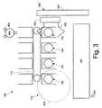
- Figs. 1-3show an example of a beverage dispensing system 100 as may be described herein.
- the overall beverage dispensing system 100may include any number of modules or stations 110. These modules or stations 110 described herein need not all be used herein, need not all be used together, and need not all be used in any particular order. Additional stations 110 and other types of components in any configuration may be used herein.
- the beverage dispensing system 100may include a cup placement station 120 with a number of cups 125, an ice dispensing station 130, a beverage dispensing station 140, a cup lidding and removal station 150 with a number of lids 155, and a printing station 160.
- Other stations 110 and other componentsmay be used herein. Some or all of the stations 110 may be positioned about a dispensing conveyor 170. An outgoing staging conveyor 180 also may be used.
- Each of these stations 110 and the other components used hereinmay be in communications with a control device 190.
- the control device 190may be a conventional micro-computer and the like capable of executing programmable commands.
- the control device 190may be internal to or removed from the beverage dispensing system 100.
- the control device 190may be responsive to instructions or requests from a number of input devices 200.
- the input devices 200may be any type of user interface, such as conventional cash registers, order monitoring systems (bump screen), touch screen, and similar types of order input devices typically found in quick service restaurants and other types of retail establishments. Instructions or requests may be entered by a crew member, a consumer, or anyone else. Any number of input devices 200 may be used herein. Other components and other configurations may be used herein.
- the cups 125may be transported from station to station herein via the dispensing conveyor 170.
- the dispensing conveyor 170may be a conventional timing belt or other types of transport devices.
- a number of cup holders 210may be positioned on the dispensing conveyor 170.
- the cup holders 210may include a number of walls 220 extending in a direction perpendicular to that of the advance of the dispensing conveyor 170.
- the walls 220may be spaced apart so as to accommodate cups 125 of varying sizes. As will be described in more detail below, the walls 220 may have a number of slots 230 therein.
- Advancement of the dispensing conveyor 170may be controlled by the control device 190. Multiple dispensing conveyors 170 may be used herein. Other components and other configurations may be used herein.
- the cup placement station 120may include a cup storage turret 240 or other type of cup storage device.
- the cup storage turret 240may include a number of cup sleeves 250.
- the cup sleeves 250may be sized for differently sized cups 125. Any number and any size of the cup sleeves 250 may be used herein with any number or any size of the cups 125.
- the cup sleeves 250may rotate about a turret pin 260 in a conventional manner in communication with the control device 190.
- a release mechanism 270may be positioned about the cup sleeves 250 so as to release an appropriately sized cup 125 into one of the cup holders 210 located in the cup placement station 120 on the dispensing conveyor 170 as instructed by the control device 190.
- Multiple cup storage turrets 240may be used herein. Other components and other configurations may be used herein.
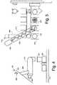
- Figs. 4-7show an example of the ice dispensing station 130.
- the ice dispensing station 130may be positioned on the dispensing conveyor 170 downstream of the cup placement station 120 or elsewhere.
- the ice dispensing station 130may include an ice bin 280.
- the ice bin 280may have any size, shape, or configuration.
- the ice bin 280has a volume of ice 290 therein.
- the ice dispensing station 130may include an ice chute 300 and an ice delivery tube 310.
- the ice chute 300may connect the ice bin 280 and the ice delivery tube 310.
- the ice chute 300may be angled downward so as to be gravity fed.
- the ice chute 300may have any size, shape, or configuration.
- the ice delivery tube 310may be attached directly to the ice bin 280.
- the ice delivery tube 310may have a slight uphill slope so as to allow any water or condensate to drain and not drip into the cup 125.
- the ice delivery tube 310may have any size, shape, or configuration.
- the ice delivery tube 310may include an auger 320 therein.
- the auger 320may be driven by an auger motor 330.
- the auger 320may be a conventional screw type device and the like.
- the auger 320may have any size, shape, or configuration.
- the auger motor 330may be a conventional electrical motor and the like. Multiple ice delivery tubes 310 and augers 320 may be used herein.
- the ice delivery tube 310may extend over the dispensing conveyer 170 so as to dispense ice 290 into a cup 125 located in the cup dispensing station 130.
- the auger 320drives the ice 290 through the ice delivery tube 310 and into the cup 225.
- the flow of ice 290is controlled by the auger 320 and the auger motor 330 in communication with the control device 190.
- the amount of ice dispensedmay be determined by a combination of the rotational rate of the auger 320 with respect to time.
- the control device 190may have a look-up table or other types of data structures and associated software so as to provide a targeted, predetermined amount of the ice 290 for a given cup size.
- the auger motor 330may dynamically adjust the torque on the auger 320 so as to overcome ice jams and blockages therein while maintaining the correct rotational rate.
- the ice delivery tube 310 and the auger 320may be removable for cleaning. Other components and other configurations may be used herein.
- the ice dispensing station 130also may include a weight sensor 335.
- the weight sensor 335may be in the form of a load cell 340 although any type of weight sensor 335 may be used.
- the load cell 340may be positioned about the dispensing conveyor 170 adjacent to the ice delivery tube 310.
- the load cell 340may include a cup interface block 350 with a number of fins 360 extending therefrom.
- the fins 360may extend upwardly into the dispensing conveyor 170.
- the fins 360may be sized to accommodate the slots 230 in the walls 220 of the cup holders 210. As a cup holder 210 with an empty cup 125 moves into the ice dispensing station 130, the slots 230 slide through the fins 360 of the cup interface block 350.
- the fins 360may slightly elevate the empty cup 125.
- the load cell 340then may determine the tare weight of the empty cup 125.
- the load cell 340subtracts the tare weight of the empty cup 125 as the ice 290 is dispensed therein.
- the load cell 340may provide feedback to the control device 190 to ensure that an accurate predetermined volume of the ice 290 is dispensed therein for a given cup size. Likewise, the correct volume ensures that the ice 290 reaches a correct fill height within the cup 125.
- Other components and other configurationsmay be used herein.
- Figs. 2 , 3 , and 5show an example of the beverage dispensing station 140.
- the dispensing station 140may be positioned along the dispensing conveyer 170 adjacent to the ice dispensing station 130 or elsewhere.
- the beverage dispensing station 140may be a beverage dispensing system such as that described in commonly owned U.S. Patent No. 7,757,896 described above.
- the beverage dispensing station 140may include a dispensing nozzle 370 for combining a number of micro-ingredients 380, a number of macro-ingredients 390, a diluent 400, and/or other ingredients.
- the micro-ingredients 380generally have reconstitution ratios of about ten to one (10:1) and higher.
- micro-ingredients 380examples include natural and artificial flavors, flavor additives, natural and artificial colors, artificial sweeteners, additives for controlling tartness, functional additives, and the like.
- the macro-ingredients 390generally have reconstitution ratios in the range of about three to one (3:1) to about six to one (6:1).
- the macro-ingredients 390may include sugar, syrup, high fructose corn syrup, juice concentrates, and the like.
- Various types of these diluentsmay be used herein, including water, carbonated water, and other fluids.
- micro-ingredients 380, the macro-ingredients 390, and the diluents 400may be mixed at the dispensing nozzle 370 or elsewhere.
- suitable dispensing nozzles 370include those described in commonly owned U.S. Patent No. 7,866,509 B2 to Ziesel , entitled “DISPENSING NOZZLE ASSEMBLY” and commonly owned U.S. Patent No. 7,578,415 B2 to Ziesel, et al. , entitled “DISPENSING NOZZLE ASSEMBLY.”
- Multiple dispensing nozzles 370may be used herein.
- Conventional dispensing nozzles with conventional beverage ingredientsalso may be used herein.
- Other components and other configurationsmay be used herein.
- the dispense of the beverage 410 from the dispensing nozzle 370may be controlled by the control device 190.
- the timing of the dispensemay vary with the nature of the beverage 410, the amount of the ice 290 within the cup 125, and other parameters.
- the control device 190may determine the target volume of the beverage 410 so as to provide the correct fill level. Specifically, the total volume of the cup contents equals the volume of the beverage plus the volume of ice. If the weight of the ice is known, the volume of the ice may be calculated for each cup size. The total volume of the beverage therein thus may be determined by subtracting the dispensed ice volume from the total target cup contents volume.
- the control device 190might adjust the amount of the beverage dispensed via an ice dispensing error amount signal to compensate for any inaccuracy in the ice amount to insure that the cup 125 is filled to the correct fill level, i.e., the adjusted target amount of the beverage 410.
- Other components and other configurationsalso may be used herein.
- the dispensealso may be momentarily paused one or more times so as to accommodate foaming of the beverage therein in the case of a carbonated beverage and the like and then resumed to provide the correct predetermined volume of the beverage therein without spillage.
- Different beverages 410may have different foaming characteristics. For example, lemonade (a non-carbonated beverage) may have no foam, a carbonated diet soft drink may have a medium level of foam, and a carbonated soft drink with flavoring may have an extreme level of foam.
- the same beverage 470also may foam differently depending on how much ice 290 is in the cup 125. The more ice 290 in the cup 125, the less foam may be created. Cup size also may affect the dispensing parameters.
- a larger cup 125 with a larger volume of beverage 470may generate a larger volume of foam as compared to a similar beverage in a smaller cup 125 and may thus require a longer wait time for foam dissipation.
- a non-foaming beveragesuch as a lemonade thus may be dispensed in one continuous pour.
- a medium foaming beveragemay be dispensed with an initial partial pour, a wait time for the foam to dissipate, then a final top-off.
- An extreme foaming beveragemay need to be dispensed in three or more pours with a longer wait times in between each pour to allow the foam to dissipate.
- An extreme foaming beveragealso may require time to allow the foam to dissipate after the final top-off before moving the cup 125.
- Each beverage 410may be characterized by the level of foam generated such that the beverage dispensing parameters may be set according to the foam level of the beverage 410, the level of ice 290 in the cup 125, and the size of the cup 125.
- Beverage dispensing parametersmay include but are not limited to: (1) the number of pours; (2) the percent of the volume of the cup 125 filled by the initial pour; (3) waiting time between pours; (4) and waiting time after the last pour before the cup begins moving. Other parameters may be used herein. By setting the beverage parameters properly, a beverage 410 may be poured in a minimum amount of time without foamingover.
- each beverage 410may be assigned a level of foaming. Any number of levels of foaming may be created. For the purposes of example six (6) levels of foaming may be used from “1": non-foaming, to "6": extreme-foaming.
- the level of foamingmay be included in a master recipe data base in the control device 190.
- Fig. 8shows a two dimensional table with a number of beverage dispensing parameters 415 assigned for each level of foaming for four different levels of ice. Such a table may be included in the software/database of the control device 190.
- the beverage dispensing parameterswill be as follows: (1) the cup 125 will be filled in two pours; (2) the initial pour will fill about 81% of the cup 125; (3) there will be a 4.5 second pause between the initial pour and the top-off; (4) there will be no wait after the top-off before the cup 125 starts moving.
- This exampleshows a two dimensional table that would apply to all cup sizes, but a third dimension could be added to the table to adjust for cup size.
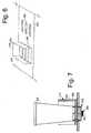
- Figs. 9-17show an example of the cup lidding and removal station 150.
- the cup lidding and removal station 150may be positioned along the dispensing conveyor 170 adjacent to the beverage dispensing station 140 or elsewhere.
- the cup lidding and removal station 150may include a gripper mechanism 420.
- the gripper mechanism 420may include a number of gripper jaws 430 that may open and close so as to accept, center, and release the cup 125.
- the gripper jaws 430may accommodate cups 125 of differing sizes.
- the gripper mechanism 420may be positioned about the dispensing conveyor 170 with the gripper jaws 430 positioned above the height of the walls 220 of the cup holder 210 so as to grip the cup 125 therein.
- the gripper mechanism 420may be mounted onto a gripper positioning device 435.
- the gripper positioning device 435may be in the form of a first horizontal linear actuator 440 and the like.
- the first horizontal linear actuator 440may be any type of device that provides substantially horizontal movement.
- the first horizontal linear actuator 440may move the gripper mechanism 420 with the cup 125 therein from the dispensing conveyor 170 to the staging conveyor 180 or elsewhere.
- Other components and other configurationsmay be used herein.
- the cup lidding and removal station 150also may include one or more lid stacks 450.
- the lid stacks 450may have a stack of the lids 155 therein.
- the lid stacks 450may include a number of posts 460 to support the lids 155 therein while providing access thereto. Although three (3) posts 460 are shown, any number of the posts 460 may be used.
- the lid stack 460also may include one or more springs 470 positioned underneath the lids 155. The springs 470 may allow a reasonable degree of over travel. Any number of the lid stacks 450 may be used. Specifically, the lid stacks 450 with differently sized lids 155 may be positioned adjacent to each other. Other components and other configurations may be used herein.
- the cup lidding and removal station 150may include a lidding mechanism 480.
- the lidding mechanism 480may include a base 490 with a number of spring clips lid retention members 495 extending therefrom.
- the lid retention members 495may be in the form of a number of spring clips 500.
- Each of the spring clips 500may include a base portion 510, a narrowing attachment portion 520, and an expanding centering portion 530.
- the spring clips 500may be made out of any type of flexible material with a sufficient amount of memory so as to resist permanent deformation while accommodating lids 155 of differing sizes. Any number of the spring clips 500 may be used herein.
- the spring clips 500may be adapted for use with lids 155 having a top portion 540 and an indented bottom portion 550.
- a proximity switch 555 and the likemay be positioned about the base 490 between the spring clips 500.
- the proximity switch 555may be in the form of a contact switch 560.
- the contact switch 560may be in communication with the control device 190.
- Other components and other configurationsmay be used herein.
- the cup lidding and removal station 150also includes a positioning device 565 for maneuvering the lidding mechanism 480.
- the positioning device 565may include a vertical linear actuator 570 and a second horizontal linear actuator 580.
- the actuators 570, 580may be in communication with the lidding mechanism 480.
- the actuators 570, 580may be any type of movement device that provides substantially vertical and/or horizontal motion.
- the base 490 of the lidding mechanism 480may be attached to the vertical linear actuator 570 for vertical motion while the vertical linear actuator 570 may be attached to the second horizontal liner actuator 580 for horizontal motion.
- the second horizontal linear actuator 580may be positioned above the first horizontal linear actuator 440.
- Other components and other configurationsmay be used.
- the gripper jaws 430engage and center the cup 125 therein with respect to the cup lidding mechanism 480.
- the lidding mechanism 480may be maneuvered by the second horizontal linear actuator 580 and the vertical linear actuator 570 to the lid stack 450 with the appropriately sized lids 155 therein. As is shown in Figs. 12-14 , the vertical linear actuator 570 then lowers the lidding mechanism 480 onto the stack of the lids 155. Because the spring clips 500 of the lidding mechanism 480 are flexible, the spring clips 500 may flex outwardly so as to accommodate differently sized lids 155.
- the centering portions 530 of the spring clips 500expand over the top lid 155.
- the attachment portion 520then snaps into place about the indented portion 550 of the lid 155.
- Actuation of the contact switch 520causes the downward motion of the vertical linear actuator 570 to cease.
- the vertical linear actuator 570then reverses direction and lifts the lid 155 out of the lid stack 450. If the lid 155 is not successfully engaged, the contact switch 560 will de-actuate as the lidding mechanism 480 moves upward. The lidding mechanism 480 then may again attempt the engagement sequence.
- the vertical linear actuator 570 and the second horizontal linear actuator 580 of the positioning device 565may maneuver the lidding mechanism 480 over the cup 125 within the gripper mechanism 420.
- Figs. 15-17show the positioning of the lid 155 on the cup 125 by the lidding mechanism 480.
- the vertical linear actuator 570may lower the lidding mechanism 480 with the lid 155 onto the cup 125.
- the base 490 of the lidding mechanism 480applies a force directly to the lid 155 to snap it onto the cup 125.
- the extent of the downward movement of the lidding mechanism 480may be dependent upon the size of the cup 125.
- the vertical linear actuator 570may move the lidding mechanism 480 to differing predetermined heights depending upon the size of the cup 125.
- the retention snap force between the cup 125 and the lid 155may be higher than that between the spring clips 500 and the lid 155 such that when the lidding mechanism 480 is again raised by the vertical linear actuator 570, the spring clips 500 may be pulled off the lid 155.
- the de-actuation of the contact switch 560indicates that the lid 155 has been successfully snapped onto the cup 125. If the contact switch 560 remains actuated, the lidding mechanism 480 may again attempt to attach the lid 155 to the cup 125.
- the first horizontal linear actuator 440may move the gripper mechanism 420 with the cup 125 to the staging conveyor 180.
- the gripper jaws 430 of the gripper mechanism 420may release the cup 125 such that the cup 125 may move out of the gripper jaws 430 as the staging conveyor 180 advances.
- a number of dispensed, lidded, and identified beveragesmay be stored on the staging conveyor 180 for order fulfillment.
- the staging conveyor 180may advance by one cup pitch each time a finished beverage is delivered to the staging conveyor 180 so as to efficiently space the staged beverages.
- the staging conveyor 180may advance by more than one cup pitch to create a relatively larger space between cups 125 to segregate cups 125 from one customer order to cups 125 from a subsequent order.
- There may be a sensor 640 at the far end of the staging conveyor 180to detect when the staging conveyor 180 is full to prevent cups 125 from falling off of the end of the staging conveyor 180. The overall cycle then may be repeated.
- Other components and other configurationsmay be used herein.
- Figs. 18-21show an example of the printing station 160.
- the printing station 160may include one or more printing heads 590.
- the printing head 590may be an ink jet printer and the like. Any type of printing mechanism adequate for quickly printing on a thermoplastic lid or other type of lid material without significant smudging may be used herein. Moreover, the printing head 590 also may apply labels and the like.
- the printing head 590may be attached to the lidding mechanism 480 of the cup lidding and removal station 150.
- the printing head 590may be attached to the lidding mechanism 480 by a pair of standoffs 600 and the like. Any type of substantially rigid attachment means may be used herein.
- the printing head 590may be positioned even with or slightly beneath the bottom of the lidding mechanism 480. Other components and other configurations may be used herein.
- the vertical linear actuator 570raises the lidding mechanism 480 to a predetermined height so as to accommodate the printing head 590.
- the printing head 590then prints one or more messages 610 thereon.
- the message 610may include a brand or other beverage identifier 620 and an order number 625.
- the message 610also may include any type of information such as an advertisement, refill information, nutritional information, a coupon, a prize, and the like. Any type of information, designs, or other indicia may be printed thereon.
- the printing head 590has been described in terms of being positioned about the lidding mechanism 480, the printing head 590 may be positioned anywhere along the travel path of the lid 155. Further, the printing head 590 also may be positioned so as to print the message 610 on the side or even the bottom of the cup 125. Multiple printing heads 590 may be used herein. Other components and other configurations may be used herein.
- the various stations 110 of beverage dispensing system 100 located about the dispensing conveyor 170 and the staging conveyor 180may be located above a drain pan 650 so that drips and spills may be appropriately routed to a drain 660.
- the staging conveyor 170 and the dispensing conveyor 180may be mounted to a deck 670 so as to be removable for cleaning.
- a motor 680 powering the dispensing conveyor 170may be located above the deck 670 so that drips and spills will not land on the motor 680.
- the disengagement of the motor 680 from the staging conveyor 170may be a simple, passive process when the deck 670 is removed for cleaning.
- Fig. 22shows the deck 670 to which the staging conveyor 180 and the dispensing conveyor 170 may be attached and located over the drain pan 650.
- the motor 680 of the dispensing conveyor 170may be mounted above the deck 670 and connected to the dispensing conveyor 170 via a number of gears 690.
- the gears 690may be disengaged by themselves when the deck 670 is removed for cleaning by tilting the deck 670 up and sliding it out.
- Other components and other configurationsmay be used herein.
- Fig. 23shows the beverage dispensing system 100 positioned within an outer frame 630. Any or all of the stations 110 may be positioned within the frame 630 and out of direct contact with a consumer. Rather, the consumer may have access to the input device 200 and the staging conveyor 190. The consumer thus requests a beverage at the input device 200.
- the cup 125 with ice 290 and a beverage 410 therein and the lid 155 thereon,then may be dispense along the staging conveyor 180.
- the lid 155likewise may have the message 610 thereon.
- Other components and other configurationsalso may be used herein.
- the beverage dispensing system 100thus automates the beverage dispensing process.
- the cup placement station 120selects the appropriately sized cup 125 and places the cup 125 within the cup holder 210 of the dispensing conveyor 170.
- the dispensing conveyer 170advances the cup 125 to the ice dispensing station 130.
- the ice dispensing station 130dispenses the appropriate predetermined volume of ice 290 therein via feedback from the load cell 340.
- the dispensing conveyor 170then advances the cup 126 to the dispensing nozzle 370.
- the dispensing nozzle 370fills the cup 125 with the appropriate predetermined volume of the desired beverage 410.
- the controller 190also may adjust the amount of the beverage dispensed to compensate for any inaccuracies in the dispensed ice as detected by the load cell 340 so that the proper fill level in the cup 125 may be achieved.
- the beverage dispensing station 140may pause during the dispense so as to accommodate foaming.
- the dispensing conveyor 170may maneuver the cup 125 to the cup lidding and removal station 150.
- the gripper mechanism 420may grab and center the cup 125.
- the lidding mechanism 480may be maneuvered by the vertical linear actuator 570 and the second horizontal linear actuator 580 of the positioning device 565 to select and remove the appropriately sized lid 155 from one of the lid stacks 450.
- the lidding mechanism 480may be maneuvered so as to attach the lid 155 to the cup 125.
- the lidding mechanism 480then may be raised and the cup 125 may begin to maneuver towards the staging conveyor 180 via the first horizontal linear actuator 440. While doing so, the cup 125 passes under the printing head 590 of the printing station 160 such that a message 610 may be printed on the lid 155 or elsewhere.
- the various stations 110 of the beverage dispensing system 100need not all be used herein together. Likewise, additional stations and additional components also may be used herein. Components may be substituted for other known components that may carry out the function of the components described herein.
- the beverage dispensing system 100thus provides a lidded and identified beverage in a fast and efficient manner. Given the high volume of beverages and the large variety that may be produced herein, the use of the brand identifier 620 is helpful to ensure that the consumer receives the correct beverage - particularly with beverages of a similar color.
- the beverage dispensing system 100also ensures that the correct amount of ice 290 is added to the beverage 410 so as to limit premature melting with too little ice or an inadequate volume of the beverage 410 therein with too much ice.
- Other types of additives or other types of ingredients in liquid, solid, or gaseous formalso may be added to the cup 125 in additional stations 110.
- Multiple beverage dispensing systems 100also may be used herein and may share certain stations 110 or other components.
- the message 610may include the brand or other type of beverage identifier 620 and the order number 625.
- the message 610also may include any type of information such as an advertisement, refill information, nutritional information, a coupon, a prize, and the like.
- the lid 155also may include a token 700 thereon.
- the token 700may be a circular token 710 as is shown in Fig. 24A , a tear out token 720 as is shown in Fig. 24B , or a doughnut token 730 as is shown in Fig. 24C .
- the tokens 700may have any size, shape, or configuration.
- the token 700may provide a substrate on the lid 155 for preventing or reducing smudging of the ink as compared to printing directly on the lid 155.
- Printing on the token 700also may enable tie-ins with loyalty programs and the like.
- a loyalty program codemay be printed on the token 700.
- a consumermay take that token 700, log in to the website of the loyalty program, and enter the code on the token 700 to earn loyalty points and the like.
- Other types of promotionsmay be used herein.
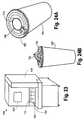
- Figs. 25 and 26show a lid 750.
- This lid 750may have an angled lead-in flair 760 extending about the perimeter.
- the angled lead-in flair 760may be continuous or intermittent.
- the angled lead-in flair 760may allow the lid 750 to find it way on to the cup 125 even if the lid 750 is somewhat off center so as to increase overall lidding tolerances and reliability.
- the lid 750also may include a number of anti-nesting features 770.
- the anti-nesting features 770may include a number of undercuts 780 formed into the lid 750 about the angled lead-in flair 760. Although four (4) undercuts 780 are shown, any number may be used herein.
- the undercuts 780may have a sufficient depth to resist nesting but shallow enough to allow the lid 750 to escape from a typical vacuum form mold. The overall vertical lid pitch may remain the same.
- the undercuts 780allow the lids 750 to be stacked in any order without nesting.
- the lids 750may be positioned on the cup 125 as is described above or the lids 750 may be used with a bottom mounted escapement type lid drop mechanism and the like. Linear or rotary devices may be used. Other components and other configurations may be used herein.
Landscapes
- Engineering & Computer Science (AREA)
- Mechanical Engineering (AREA)
- Physics & Mathematics (AREA)
- General Physics & Mathematics (AREA)
- Theoretical Computer Science (AREA)
- General Engineering & Computer Science (AREA)
- Beverage Vending Machines With Cups, And Gas Or Electricity Vending Machines (AREA)
- Closures For Containers (AREA)
- Apparatus For Making Beverages (AREA)
- Closing Of Containers (AREA)
Description
- The present application and the resultant patent relate generally to beverage dispensing systems and more particularly relate to an automated beverage dispensing system with cup lidding and beverage identification stations for fast and efficient service.
- Beverage dispensers traditionally combine a diluent such as water with a beverage base such as syrups and the like. These beverage bases generally have a dilution or a reconstitution ratio of about three to one (3:1) to about six to one (6:1). The beverage bases usually come in large bag-in-box containers that require significant amounts of storage space and may need to be refrigerated. These storage requirements often necessitate the need to position these bag-in-box containers away from the dispenser in a backroom with a long supply line. Each bag-in-box container usually only holds a beverage base for a single type or flavor of beverage such that multiple containers may be required to provide the consumer with a variety of beverage options.
- Resent improvements in beverage dispensing technology have focused on the use of micro-ingredients. With micro-ingredients, the traditional beverage bases may be separated into their constituent parts at much higher reconstitution ratios. These micro-ingredients then may be stored in much smaller packages and stored closer to, adjacent to, or within the beverage dispenser itself. The beverage dispenser preferably may provide the consumer with multiple beverage options as well as the ability to customize his or her beverage as desired.
- Beverage dispensers incorporating such highly concentrated micro-ingredients have proven to be highly popular with consumers. One example of the use of such micro-ingredients is shown in commonly owned
U.S. Patent No. 7,757,896 B2 to Carpenter, et al. , entitled "BEVERAGE DISPENSING SYSTEM." Likewise, such micro-ingredient technology is incorporated in the highly popular "FREESTYLE®" refrigerated beverage dispensing units provided by The Coca-Cola Company of Atlanta, Georgia. The "FREESTYLE®" refrigerated beverage dispensing units can dispense over 125 brands without the need for extensive storage space. - There is now a desire to incorporate such micro-ingredient technology for behind the counter or crew serve applications in venues such as quick service restaurants and the like. The use of such micro-ingredient technology would allow the venue to offer dozens of different beverages without significant storage requirements in a fast and efficient manner.
US 5000345 A discloses a beverage dispenser which includes a lid application mechanism.DE 3111896 C1 discloses a pot-filling appliance with a lid-receiving phase.- The present application and the resultant patent thus provide an automated beverage dispenser using a number of cups and a number of lids, comprising: a lid stack with the number of lids; and a lidding mechanism; characterised in that: the lidding mechanism comprises a base with a plurality of lid attachment members; and the automated beverage dispenser further comprises a positioning device for maneuvering the lidding mechanism so as to remove one of the number of lids by the plurality of lid attachment members from the lid stack and to snap the lid on to one of the number of cups by the base.
- The present application and the resultant patent further provide a method of placing a lid on a cup in an automated beverage dispenser, comprising: maneuvering a lidding mechanism with a base and a number of lid attachment members about a lid stack; lowering the lidding mechanism on to the lid stack until a contact switch is actuated by the lid; raising the lidding mechanism to remove the lid from the lid stack; maneuvering the lidding mechanism about the cup; and lowering the lidding mechanism by a predetermined distance so as to snap the lid on the cup.
Fig. 1 is a schematic diagram of an example of a beverage dispensing system as may be described herein.Fig. 2 is a side view of an example of the beverage dispensing system ofFig. 1 .Fig. 3 is a top view of an example of the beverage dispensing system ofFig. 1 with portions of the cup lidding and removal station removed for clarity.Fig. 4 is a partial side view of an example of an ice dispensing station as may be described herein.Fig. 5 is a top plan view of the ice dispensing station ofFig. 4 with portions of the cup lidding and removal station removed for clarity.Fig. 6 is a partial perspective view of the ice dispensing station ofFig. 4 .Fig. 7 is a partial side cross-sectional view of the ice dispensing station ofFig. 4 .Fig. 8 is a chart showing beverage dispensing parameters as a function of foam level and the amount of ice.Fig. 9 is a top plan view of an example of a cup lidding and removal station as may be described herein showing a lidding mechanism and a lid stack.Fig. 10 is a partial side view of the cup lidding and removal station ofFig. 9 .Fig. 11 is a further top plan view of the cup lidding and removal station ofFig 8 .Fig. 12 is a partial side cross-sectional view of a lidding mechanism of the cup lidding and removal station ofFig. 9 in use.Fig. 13 is a partial side cross-sectional view of a lidding mechanism of the cup lidding and removal station ofFig. 9 in use.Fig. 14 is a partial side cross-sectional view of a lidding mechanism of the cup lidding and removal station ofFig. 9 in use.Fig. 15 is a partial side cross-sectional view of a lidding mechanism of the cup lidding and removal station ofFig. 9 in use.Fig. 16 is a partial side cross-sectional view of a lidding mechanism of the cup lidding and removal station ofFig. 9 in use.Fig. 17 is a partial side cross-sectional view of a lidding mechanism of the cup lidding and removal station ofFig. 9 in use.Fig. 18 is a top view of an example of a printing station as may be described herein with a printer head.Fig. 19 is a side view of printing station ofFig. 18 with the printer head in use.Fig. 20 is a side view of printing station ofFig. 18 with the printer head in use.Fig. 21 is a top view of a lid as may be described herein with identification indicia printed thereon.Fig. 22 is a partial side cross-section view of the dispensing conveyor and the staging conveyor of the beverage dispensing system positioned about a drain pan.Fig. 23 is a perspective view of an example of an alternative embodiment of a beverage dispensing system as may be described herein.Figs. 24A-24C show perspective view of lids with tokens as may be described herein.Fig. 25 is a plan view of a lid as may be described herein.Fig. 26 is a side plan view of a stack of the lids ofFig. 25 .- Referring now to the drawings, in which like numerals refer to like elements throughout the several views,
Figs. 1-3 show an example of abeverage dispensing system 100 as may be described herein. As will be described in more detail below, the overallbeverage dispensing system 100 may include any number of modules orstations 110. These modules orstations 110 described herein need not all be used herein, need not all be used together, and need not all be used in any particular order.Additional stations 110 and other types of components in any configuration may be used herein. - Generally described, the
beverage dispensing system 100 may include acup placement station 120 with a number ofcups 125, anice dispensing station 130, abeverage dispensing station 140, a cup lidding andremoval station 150 with a number oflids 155, and aprinting station 160.Other stations 110 and other components may be used herein. Some or all of thestations 110 may be positioned about a dispensingconveyor 170. Anoutgoing staging conveyor 180 also may be used. Each of thesestations 110 and the other components used herein may be in communications with acontrol device 190. Thecontrol device 190 may be a conventional micro-computer and the like capable of executing programmable commands. Thecontrol device 190 may be internal to or removed from thebeverage dispensing system 100. Thecontrol device 190 may be responsive to instructions or requests from a number ofinput devices 200. Theinput devices 200 may be any type of user interface, such as conventional cash registers, order monitoring systems (bump screen), touch screen, and similar types of order input devices typically found in quick service restaurants and other types of retail establishments. Instructions or requests may be entered by a crew member, a consumer, or anyone else. Any number ofinput devices 200 may be used herein. Other components and other configurations may be used herein. - The
cups 125 may be transported from station to station herein via the dispensingconveyor 170. The dispensingconveyor 170 may be a conventional timing belt or other types of transport devices. A number ofcup holders 210 may be positioned on the dispensingconveyor 170. Thecup holders 210 may include a number ofwalls 220 extending in a direction perpendicular to that of the advance of the dispensingconveyor 170. Thewalls 220 may be spaced apart so as to accommodatecups 125 of varying sizes. As will be described in more detail below, thewalls 220 may have a number ofslots 230 therein. Advancement of the dispensingconveyor 170 may be controlled by thecontrol device 190.Multiple dispensing conveyors 170 may be used herein. Other components and other configurations may be used herein. - The
cup placement station 120 may include acup storage turret 240 or other type of cup storage device. Thecup storage turret 240 may include a number ofcup sleeves 250. Thecup sleeves 250 may be sized for differentlysized cups 125. Any number and any size of thecup sleeves 250 may be used herein with any number or any size of thecups 125. Thecup sleeves 250 may rotate about aturret pin 260 in a conventional manner in communication with thecontrol device 190. Arelease mechanism 270 may be positioned about thecup sleeves 250 so as to release an appropriatelysized cup 125 into one of thecup holders 210 located in thecup placement station 120 on the dispensingconveyor 170 as instructed by thecontrol device 190. Multiplecup storage turrets 240 may be used herein. Other components and other configurations may be used herein. Figs. 4-7 show an example of theice dispensing station 130. Theice dispensing station 130 may be positioned on the dispensingconveyor 170 downstream of thecup placement station 120 or elsewhere. Theice dispensing station 130 may include anice bin 280. Theice bin 280 may have any size, shape, or configuration. Theice bin 280 has a volume ofice 290 therein. Theice dispensing station 130 may include anice chute 300 and anice delivery tube 310. Theice chute 300 may connect theice bin 280 and theice delivery tube 310. Theice chute 300 may be angled downward so as to be gravity fed. Theice chute 300 may have any size, shape, or configuration. Alternatively, theice delivery tube 310 may be attached directly to theice bin 280. Theice delivery tube 310 may have a slight uphill slope so as to allow any water or condensate to drain and not drip into thecup 125. Theice delivery tube 310 may have any size, shape, or configuration. Theice delivery tube 310 may include anauger 320 therein. Theauger 320 may be driven by anauger motor 330. Theauger 320 may be a conventional screw type device and the like. Theauger 320 may have any size, shape, or configuration. Theauger motor 330 may be a conventional electrical motor and the like. Multipleice delivery tubes 310 andaugers 320 may be used herein.- The
ice delivery tube 310 may extend over the dispensingconveyer 170 so as to dispenseice 290 into acup 125 located in thecup dispensing station 130. Theauger 320 drives theice 290 through theice delivery tube 310 and into the cup 225. The flow ofice 290 is controlled by theauger 320 and theauger motor 330 in communication with thecontrol device 190. The amount of ice dispensed may be determined by a combination of the rotational rate of theauger 320 with respect to time. Thecontrol device 190 may have a look-up table or other types of data structures and associated software so as to provide a targeted, predetermined amount of theice 290 for a given cup size. Moreover, modifications also may be requested,i.e., no ice, light ice, normal ice, or extra ice as directed by theinput devices 200. Theauger motor 330 may dynamically adjust the torque on theauger 320 so as to overcome ice jams and blockages therein while maintaining the correct rotational rate. Theice delivery tube 310 and theauger 320 may be removable for cleaning. Other components and other configurations may be used herein. - The
ice dispensing station 130 also may include aweight sensor 335. In this example, theweight sensor 335 may be in the form of aload cell 340 although any type ofweight sensor 335 may be used. Theload cell 340 may be positioned about the dispensingconveyor 170 adjacent to theice delivery tube 310. Theload cell 340 may include acup interface block 350 with a number offins 360 extending therefrom. Thefins 360 may extend upwardly into the dispensingconveyor 170. Thefins 360 may be sized to accommodate theslots 230 in thewalls 220 of thecup holders 210. As acup holder 210 with anempty cup 125 moves into theice dispensing station 130, theslots 230 slide through thefins 360 of thecup interface block 350. Thefins 360 may slightly elevate theempty cup 125. Theload cell 340 then may determine the tare weight of theempty cup 125. Theload cell 340 subtracts the tare weight of theempty cup 125 as theice 290 is dispensed therein. Theload cell 340 may provide feedback to thecontrol device 190 to ensure that an accurate predetermined volume of theice 290 is dispensed therein for a given cup size. Likewise, the correct volume ensures that theice 290 reaches a correct fill height within thecup 125. Other components and other configurations may be used herein. Figs. 2 ,3 , and5 show an example of thebeverage dispensing station 140. The dispensingstation 140 may be positioned along the dispensingconveyer 170 adjacent to theice dispensing station 130 or elsewhere. Thebeverage dispensing station 140 may be a beverage dispensing system such as that described in commonly ownedU.S. Patent No. 7,757,896 described above. Thebeverage dispensing station 140 may include a dispensingnozzle 370 for combining a number ofmicro-ingredients 380, a number ofmacro-ingredients 390, a diluent 400, and/or other ingredients. The micro-ingredients 380 generally have reconstitution ratios of about ten to one (10:1) and higher. Examples of the micro-ingredients 380 include natural and artificial flavors, flavor additives, natural and artificial colors, artificial sweeteners, additives for controlling tartness, functional additives, and the like. The macro-ingredients 390 generally have reconstitution ratios in the range of about three to one (3:1) to about six to one (6:1). The macro-ingredients 390 may include sugar, syrup, high fructose corn syrup, juice concentrates, and the like. Various types of these diluents may be used herein, including water, carbonated water, and other fluids.- The micro-ingredients 380, the
macro-ingredients 390, and thediluents 400 may be mixed at the dispensingnozzle 370 or elsewhere. Example of suitable dispensingnozzles 370 include those described in commonly ownedU.S. Patent No. 7,866,509 B2 to Ziesel , entitled "DISPENSING NOZZLE ASSEMBLY" and commonly ownedU.S. Patent No. 7,578,415 B2 to Ziesel, et al. , entitled "DISPENSING NOZZLE ASSEMBLY." Multiple dispensingnozzles 370 may be used herein. Conventional dispensing nozzles with conventional beverage ingredients also may be used herein. Other components and other configurations may be used herein. - The dispense of the
beverage 410 from the dispensingnozzle 370 may be controlled by thecontrol device 190. The timing of the dispense may vary with the nature of thebeverage 410, the amount of theice 290 within thecup 125, and other parameters. For example, thecontrol device 190 may determine the target volume of thebeverage 410 so as to provide the correct fill level. Specifically, the total volume of the cup contents equals the volume of the beverage plus the volume of ice. If the weight of the ice is known, the volume of the ice may be calculated for each cup size. The total volume of the beverage therein thus may be determined by subtracting the dispensed ice volume from the total target cup contents volume. For example, if at the end of the ice dispensing theload cell 340 detects that too much or too little ice has been dispensed into thecup 125, thecontrol device 190 might adjust the amount of the beverage dispensed via an ice dispensing error amount signal to compensate for any inaccuracy in the ice amount to insure that thecup 125 is filled to the correct fill level, i.e., the adjusted target amount of thebeverage 410. Other components and other configurations also may be used herein. - The dispense also may be momentarily paused one or more times so as to accommodate foaming of the beverage therein in the case of a carbonated beverage and the like and then resumed to provide the correct predetermined volume of the beverage therein without spillage.
Different beverages 410 may have different foaming characteristics. For example, lemonade (a non-carbonated beverage) may have no foam, a carbonated diet soft drink may have a medium level of foam, and a carbonated soft drink with flavoring may have an extreme level of foam. Thesame beverage 470 also may foam differently depending on howmuch ice 290 is in thecup 125. Themore ice 290 in thecup 125, the less foam may be created. Cup size also may affect the dispensing parameters. Alarger cup 125 with a larger volume ofbeverage 470 may generate a larger volume of foam as compared to a similar beverage in asmaller cup 125 and may thus require a longer wait time for foam dissipation. A non-foaming beverage such as a lemonade thus may be dispensed in one continuous pour. A medium foaming beverage may be dispensed with an initial partial pour, a wait time for the foam to dissipate, then a final top-off. An extreme foaming beverage may need to be dispensed in three or more pours with a longer wait times in between each pour to allow the foam to dissipate. An extreme foaming beverage also may require time to allow the foam to dissipate after the final top-off before moving thecup 125. - Each
beverage 410 may be characterized by the level of foam generated such that the beverage dispensing parameters may be set according to the foam level of thebeverage 410, the level ofice 290 in thecup 125, and the size of thecup 125. Beverage dispensing parameters may include but are not limited to: (1) the number of pours; (2) the percent of the volume of thecup 125 filled by the initial pour; (3) waiting time between pours; (4) and waiting time after the last pour before the cup begins moving. Other parameters may be used herein. By setting the beverage parameters properly, abeverage 410 may be poured in a minimum amount of time without foamingover. - Specifically, each
beverage 410 may be assigned a level of foaming. Any number of levels of foaming may be created. For the purposes of example six (6) levels of foaming may be used from "1": non-foaming, to "6": extreme-foaming. The level of foaming may be included in a master recipe data base in thecontrol device 190.Fig. 8 shows a two dimensional table with a number ofbeverage dispensing parameters 415 assigned for each level of foaming for four different levels of ice. Such a table may be included in the software/database of thecontrol device 190. By way of example, if carbonated diet soft drink has a foam level of 3, then according to the table, if medium ice is selected, then the beverage dispensing parameters will be as follows: (1) thecup 125 will be filled in two pours; (2) the initial pour will fill about 81% of thecup 125; (3) there will be a 4.5 second pause between the initial pour and the top-off; (4) there will be no wait after the top-off before thecup 125 starts moving. This example shows a two dimensional table that would apply to all cup sizes, but a third dimension could be added to the table to adjust for cup size. Figs. 9-17 show an example of the cup lidding andremoval station 150. The cup lidding andremoval station 150 may be positioned along the dispensingconveyor 170 adjacent to thebeverage dispensing station 140 or elsewhere. The cup lidding andremoval station 150 may include agripper mechanism 420. Thegripper mechanism 420 may include a number ofgripper jaws 430 that may open and close so as to accept, center, and release thecup 125. Thegripper jaws 430 may accommodatecups 125 of differing sizes. Thegripper mechanism 420 may be positioned about the dispensingconveyor 170 with thegripper jaws 430 positioned above the height of thewalls 220 of thecup holder 210 so as to grip thecup 125 therein. Thegripper mechanism 420 may be mounted onto agripper positioning device 435. In this example, thegripper positioning device 435 may be in the form of a first horizontallinear actuator 440 and the like. The first horizontallinear actuator 440 may be any type of device that provides substantially horizontal movement. The first horizontallinear actuator 440 may move thegripper mechanism 420 with thecup 125 therein from the dispensingconveyor 170 to thestaging conveyor 180 or elsewhere. Other components and other configurations may be used herein.- The cup lidding and
removal station 150 also may include one or more lid stacks 450. The lid stacks 450 may have a stack of thelids 155 therein. The lid stacks 450 may include a number ofposts 460 to support thelids 155 therein while providing access thereto. Although three (3) posts 460 are shown, any number of theposts 460 may be used. Thelid stack 460 also may include one ormore springs 470 positioned underneath thelids 155. Thesprings 470 may allow a reasonable degree of over travel. Any number of the lid stacks 450 may be used. Specifically, the lid stacks 450 with differentlysized lids 155 may be positioned adjacent to each other. Other components and other configurations may be used herein. - The cup lidding and
removal station 150 may include alidding mechanism 480. Thelidding mechanism 480 may include a base 490 with a number of spring clipslid retention members 495 extending therefrom. In this example, thelid retention members 495 may be in the form of a number of spring clips 500. Each of the spring clips 500 may include abase portion 510, a narrowingattachment portion 520, and an expanding centeringportion 530. The spring clips 500 may be made out of any type of flexible material with a sufficient amount of memory so as to resist permanent deformation while accommodatinglids 155 of differing sizes. Any number of the spring clips 500 may be used herein. The spring clips 500 may be adapted for use withlids 155 having a top portion 540 and an indented bottom portion 550. Other shapes and other types oflid retention members 495 may be used herein. A proximity switch 555 and the like may be positioned about the base 490 between the spring clips 500. The proximity switch 555 may be in the form of acontact switch 560. Thecontact switch 560 may be in communication with thecontrol device 190. Other components and other configurations may be used herein. - The cup lidding and
removal station 150 also includes apositioning device 565 for maneuvering thelidding mechanism 480. Thepositioning device 565 may include a verticallinear actuator 570 and a second horizontallinear actuator 580. Theactuators lidding mechanism 480. Theactuators base 490 of thelidding mechanism 480 may be attached to the verticallinear actuator 570 for vertical motion while the verticallinear actuator 570 may be attached to the secondhorizontal liner actuator 580 for horizontal motion. The second horizontallinear actuator 580 may be positioned above the first horizontallinear actuator 440. Other components and other configurations may be used. - When the dispensing
conveyor 170 delivers afull cup 125 to thegripper mechanism 420, thegripper jaws 430 engage and center thecup 125 therein with respect to thecup lidding mechanism 480. At any point in the dispensing process, thelidding mechanism 480 may be maneuvered by the second horizontallinear actuator 580 and the verticallinear actuator 570 to thelid stack 450 with the appropriatelysized lids 155 therein. As is shown inFigs. 12-14 , the verticallinear actuator 570 then lowers thelidding mechanism 480 onto the stack of thelids 155. Because the spring clips 500 of thelidding mechanism 480 are flexible, the spring clips 500 may flex outwardly so as to accommodate differentlysized lids 155. As thelidding mechanism 480 is lowered, the centeringportions 530 of the spring clips 500 expand over thetop lid 155. Theattachment portion 520 then snaps into place about the indented portion 550 of thelid 155. Continued downward motion of thelidding mechanism 480 actuates thecontact switch 560 positioned in thebase 490. Actuation of thecontact switch 520 causes the downward motion of the verticallinear actuator 570 to cease. The verticallinear actuator 570 then reverses direction and lifts thelid 155 out of thelid stack 450. If thelid 155 is not successfully engaged, thecontact switch 560 will de-actuate as thelidding mechanism 480 moves upward. Thelidding mechanism 480 then may again attempt the engagement sequence. - If the
lid 155 is successfully engaged as indicated by continued actuation of thecontact switch 560, the verticallinear actuator 570 and the second horizontallinear actuator 580 of thepositioning device 565 may maneuver thelidding mechanism 480 over thecup 125 within thegripper mechanism 420.Figs. 15-17 show the positioning of thelid 155 on thecup 125 by thelidding mechanism 480. The verticallinear actuator 570 may lower thelidding mechanism 480 with thelid 155 onto thecup 125. Thebase 490 of thelidding mechanism 480 applies a force directly to thelid 155 to snap it onto thecup 125. The extent of the downward movement of thelidding mechanism 480 may be dependent upon the size of thecup 125. The verticallinear actuator 570 may move thelidding mechanism 480 to differing predetermined heights depending upon the size of thecup 125. The retention snap force between thecup 125 and thelid 155 may be higher than that between the spring clips 500 and thelid 155 such that when thelidding mechanism 480 is again raised by the verticallinear actuator 570, the spring clips 500 may be pulled off thelid 155. The de-actuation of thecontact switch 560 indicates that thelid 155 has been successfully snapped onto thecup 125. If thecontact switch 560 remains actuated, thelidding mechanism 480 may again attempt to attach thelid 155 to thecup 125. - Once the
lidding mechanism 480 is clear of thecup 125, the first horizontallinear actuator 440 may move thegripper mechanism 420 with thecup 125 to thestaging conveyor 180. Thegripper jaws 430 of thegripper mechanism 420 may release thecup 125 such that thecup 125 may move out of thegripper jaws 430 as the stagingconveyor 180 advances. A number of dispensed, lidded, and identified beverages may be stored on thestaging conveyor 180 for order fulfillment. The stagingconveyor 180 may advance by one cup pitch each time a finished beverage is delivered to thestaging conveyor 180 so as to efficiently space the staged beverages. The stagingconveyor 180 may advance by more than one cup pitch to create a relatively larger space betweencups 125 to segregatecups 125 from one customer order tocups 125 from a subsequent order. There may be asensor 640 at the far end of the stagingconveyor 180 to detect when the stagingconveyor 180 is full to preventcups 125 from falling off of the end of the stagingconveyor 180. The overall cycle then may be repeated. Other components and other configurations may be used herein. Figs. 18-21 show an example of theprinting station 160. Theprinting station 160 may include one or more printing heads 590. Theprinting head 590 may be an ink jet printer and the like. Any type of printing mechanism adequate for quickly printing on a thermoplastic lid or other type of lid material without significant smudging may be used herein. Moreover, theprinting head 590 also may apply labels and the like. Theprinting head 590 may be attached to thelidding mechanism 480 of the cup lidding andremoval station 150. Theprinting head 590 may be attached to thelidding mechanism 480 by a pair ofstandoffs 600 and the like. Any type of substantially rigid attachment means may be used herein. Theprinting head 590 may be positioned even with or slightly beneath the bottom of thelidding mechanism 480. Other components and other configurations may be used herein.- After the
lidding mechanism 480 attaches thelid 155 to thecup 125 as described above, the verticallinear actuator 570 raises thelidding mechanism 480 to a predetermined height so as to accommodate theprinting head 590. As the first horizontallinear actuator 440 and thegripper mechanism 420 move thecup 125 towards the stagingconveyor 180, thelid 155 may pass underneath theprinting head 590. Theprinting head 590 then prints one ormore messages 610 thereon. Themessage 610 may include a brand orother beverage identifier 620 and anorder number 625. Themessage 610 also may include any type of information such as an advertisement, refill information, nutritional information, a coupon, a prize, and the like. Any type of information, designs, or other indicia may be printed thereon. - Although the
printing head 590 has been described in terms of being positioned about thelidding mechanism 480, theprinting head 590 may be positioned anywhere along the travel path of thelid 155. Further, theprinting head 590 also may be positioned so as to print themessage 610 on the side or even the bottom of thecup 125. Multiple printing heads 590 may be used herein. Other components and other configurations may be used herein. - The
various stations 110 ofbeverage dispensing system 100 located about the dispensingconveyor 170 and thestaging conveyor 180 may be located above adrain pan 650 so that drips and spills may be appropriately routed to adrain 660. The stagingconveyor 170 and the dispensingconveyor 180 may be mounted to adeck 670 so as to be removable for cleaning. Moreover, amotor 680 powering the dispensingconveyor 170 may be located above thedeck 670 so that drips and spills will not land on themotor 680. The disengagement of themotor 680 from the stagingconveyor 170 may be a simple, passive process when thedeck 670 is removed for cleaning. Fig. 22 shows thedeck 670 to which thestaging conveyor 180 and the dispensingconveyor 170 may be attached and located over thedrain pan 650. Themotor 680 of the dispensingconveyor 170 may be mounted above thedeck 670 and connected to the dispensingconveyor 170 via a number ofgears 690. Thegears 690 may be disengaged by themselves when thedeck 670 is removed for cleaning by tilting thedeck 670 up and sliding it out. Other components and other configurations may be used herein.- Although the
beverage dispensing system 100 has been described in the context of a behind the counter or a crew serve environment, thebeverage dispensing system 100 also may be used in a freestanding or customer serve mode. For example,Fig. 23 shows thebeverage dispensing system 100 positioned within anouter frame 630. Any or all of thestations 110 may be positioned within theframe 630 and out of direct contact with a consumer. Rather, the consumer may have access to theinput device 200 and thestaging conveyor 190. The consumer thus requests a beverage at theinput device 200. Thecup 125 withice 290 and abeverage 410 therein and thelid 155 thereon, then may be dispense along the stagingconveyor 180. Thelid 155 likewise may have themessage 610 thereon. Other components and other configurations also may be used herein. - The
beverage dispensing system 100 thus automates the beverage dispensing process. In response to a request for a beverage at theinput device 200, thecup placement station 120 selects the appropriatelysized cup 125 and places thecup 125 within thecup holder 210 of the dispensingconveyor 170. The dispensingconveyer 170 advances thecup 125 to theice dispensing station 130. Theice dispensing station 130 dispenses the appropriate predetermined volume ofice 290 therein via feedback from theload cell 340. The dispensingconveyor 170 then advances the cup 126 to the dispensingnozzle 370. The dispensingnozzle 370 fills thecup 125 with the appropriate predetermined volume of the desiredbeverage 410. Thecontroller 190 also may adjust the amount of the beverage dispensed to compensate for any inaccuracies in the dispensed ice as detected by theload cell 340 so that the proper fill level in thecup 125 may be achieved. Thebeverage dispensing station 140 may pause during the dispense so as to accommodate foaming. The dispensingconveyor 170 may maneuver thecup 125 to the cup lidding andremoval station 150. Thegripper mechanism 420 may grab and center thecup 125. Thelidding mechanism 480 may be maneuvered by the verticallinear actuator 570 and the second horizontallinear actuator 580 of thepositioning device 565 to select and remove the appropriatelysized lid 155 from one of the lid stacks 450. Thelidding mechanism 480 may be maneuvered so as to attach thelid 155 to thecup 125. Thelidding mechanism 480 then may be raised and thecup 125 may begin to maneuver towards the stagingconveyor 180 via the first horizontallinear actuator 440. While doing so, thecup 125 passes under theprinting head 590 of theprinting station 160 such that amessage 610 may be printed on thelid 155 or elsewhere. - As described above, the
various stations 110 of thebeverage dispensing system 100 need not all be used herein together. Likewise, additional stations and additional components also may be used herein. Components may be substituted for other known components that may carry out the function of the components described herein. Thebeverage dispensing system 100 thus provides a lidded and identified beverage in a fast and efficient manner. Given the high volume of beverages and the large variety that may be produced herein, the use of thebrand identifier 620 is helpful to ensure that the consumer receives the correct beverage - particularly with beverages of a similar color. Thebeverage dispensing system 100 also ensures that the correct amount ofice 290 is added to thebeverage 410 so as to limit premature melting with too little ice or an inadequate volume of thebeverage 410 therein with too much ice. Other types of additives or other types of ingredients in liquid, solid, or gaseous form also may be added to thecup 125 inadditional stations 110. Multiplebeverage dispensing systems 100 also may be used herein and may sharecertain stations 110 or other components. - As is described above, the
message 610 may include the brand or other type ofbeverage identifier 620 and theorder number 625. Themessage 610 also may include any type of information such as an advertisement, refill information, nutritional information, a coupon, a prize, and the like. As is shown inFigs. 24A-24C , thelid 155 also may include a token 700 thereon. The token 700 may be acircular token 710 as is shown inFig. 24A , a tear outtoken 720 as is shown inFig. 24B , or adoughnut token 730 as is shown inFig. 24C . Thetokens 700 may have any size, shape, or configuration. The token 700 may provide a substrate on thelid 155 for preventing or reducing smudging of the ink as compared to printing directly on thelid 155. Printing on the token 700 also may enable tie-ins with loyalty programs and the like. For example, a loyalty program code may be printed on thetoken 700. A consumer may take that token 700, log in to the website of the loyalty program, and enter the code on the token 700 to earn loyalty points and the like. Other types of promotions may be used herein. - Different type of
lids 155 also may be used with thebeverage dispensing system 100. For example,Figs. 25 and 26 show alid 750. Thislid 750 may have an angled lead-inflair 760 extending about the perimeter. The angled lead-inflair 760 may be continuous or intermittent. The angled lead-inflair 760 may allow thelid 750 to find it way on to thecup 125 even if thelid 750 is somewhat off center so as to increase overall lidding tolerances and reliability. - The
lid 750 also may include a number of anti-nesting features 770. The anti-nesting features 770 may include a number ofundercuts 780 formed into thelid 750 about the angled lead-inflair 760. Although four (4) undercuts 780 are shown, any number may be used herein. Theundercuts 780 may have a sufficient depth to resist nesting but shallow enough to allow thelid 750 to escape from a typical vacuum form mold. The overall vertical lid pitch may remain the same. Theundercuts 780 allow thelids 750 to be stacked in any order without nesting. Thelids 750 may be positioned on thecup 125 as is described above or thelids 750 may be used with a bottom mounted escapement type lid drop mechanism and the like. Linear or rotary devices may be used. Other components and other configurations may be used herein.
Claims (14)
- An automated beverage dispenser (100) using a number of cups (125) and a number of lids (155), comprising:a lid stack (450) with the number of lids; anda lidding mechanism (480);characterised in that:the lidding mechanism comprises a base (490) with a plurality of lid attachment members (495); andthe automated beverage dispenser further comprises a positioning device (565) for maneuvering the lidding mechanism so as to remove one of the number of lids by the plurality of lid attachment members from the lid stack and to snap the lid on to one of the number of cups by the base.
- The automated beverage dispenser of claim 1, wherein the plurality of lid attachment members comprises a plurality of spring clips (500).
- The automated beverage dispenser of claim 1, wherein the plurality of lid retention members comprises a narrowing attachment portion (520) and an expanding centering portion (530).
- The automated beverage dispenser of claim 1, wherein the base comprises a proximity switch (555) thereon.
- The automated beverage dispenser of claim 4, wherein the proximity switch comprises a contact switch (560).
- The automated beverage dispenser of claim 1, wherein the positioning device comprises a vertical actuator (570) and/or a horizontal actuator (580).
- The automated beverage dispenser of claim 1, further comprising a gripper mechanism (420) to position one of the number of cups therein.
- The automated beverage dispenser of claim 7, wherein the gripper mechanism comprises a plurality of gripper jaws (430).
- The automated beverage dispenser of claim 7, further comprising a positioning device (435) to maneuver the gripper mechanism.
- The automated beverage dispenser of claim 9, wherein the positioning device comprises a linear actuator (440).
- The automated beverage dispenser of claim 1, wherein the lid stack comprises one or more springs (470) therein.
- The automated beverage dispenser of claim 1, further comprising a printing head (590) positioned about the lidding mechanism.
- The automated beverage dispenser of claim 1, further comprising a dispensing nozzle (370) positioned about a dispensing conveyor (170) and wherein the dispensing nozzle dispenses a number of micro-ingredients (380) therethrough.
- A method of placing a lid (155) on a cup (125) in an automated beverage dispenser (100), comprising:maneuvering a lidding mechanism (480) with a base (490) and a number of lid attachment members (495) about a lid stack (450);lowering the lidding mechanism on to the lid stack until a contact switch (555; 560) is actuated by the lid;raising the lidding mechanism to remove the lid from the lid stack;maneuvering the lidding mechanism about the cup; andlowering the lidding mechanism by a predetermined distance so as to snap the lid on the cup.
Applications Claiming Priority (2)
| Application Number | Priority Date | Filing Date | Title |
|---|---|---|---|
| US201261603404P | 2012-02-27 | 2012-02-27 | |
| PCT/US2013/027894WO2013130514A1 (en) | 2012-02-27 | 2013-02-27 | Automated beverage dispensing system with cup lidding and beverage identification |
Publications (2)
| Publication Number | Publication Date |
|---|---|
| EP2819922A1 EP2819922A1 (en) | 2015-01-07 |
| EP2819922B1true EP2819922B1 (en) | 2016-04-20 |
Family
ID=47844509
Family Applications (1)
| Application Number | Title | Priority Date | Filing Date |
|---|---|---|---|
| EP13708614.6AActiveEP2819922B1 (en) | 2012-02-27 | 2013-02-27 | Automated beverage dispensing system with cup lidding and method of placing a lid on a cup |
Country Status (6)
| Country | Link |
|---|---|
| US (1) | US9141562B2 (en) |
| EP (1) | EP2819922B1 (en) |
| AU (1) | AU2013205567B2 (en) |
| CA (1) | CA2865590C (en) |
| MX (1) | MX349454B (en) |
| WO (1) | WO2013130514A1 (en) |
Families Citing this family (36)
| Publication number | Priority date | Publication date | Assignee | Title |
|---|---|---|---|---|
| US9499385B1 (en)* | 2009-04-17 | 2016-11-22 | Briggo, Inc. | System and method for brewing and dispensing coffee using customer profiling |
| US20130238118A1 (en)* | 2012-01-30 | 2013-09-12 | Alfred M. Haas | fD |
| MX349455B (en)* | 2012-02-27 | 2017-07-31 | Coca Cola Co | Automated beverage dispensing system with ice and beverage dispensing. |
| US20130282164A1 (en)* | 2012-04-20 | 2013-10-24 | Balagru K. Veloo | Automated restaurant beverage device and method |
| US9675206B2 (en)* | 2012-07-06 | 2017-06-13 | Carrier Corporation | Multi-position beverage dispenser |
| US9527716B2 (en) | 2013-11-22 | 2016-12-27 | Michael J. Kline | System, method, and apparatus for purchasing, dispensing, or sampling of products |
| US9701530B2 (en) | 2013-11-22 | 2017-07-11 | Michael J. Kline | System, method, and apparatus for purchasing, dispensing, or sampling of products |
| US9633504B2 (en) | 2013-11-22 | 2017-04-25 | Michael J Kline | System, method, and apparatus for purchasing, dispensing, or sampling of products |
| US11178914B2 (en)* | 2014-05-23 | 2021-11-23 | Revolutionary Electronic Design, LLC | Vaping liquid dispensing and vending |
| US10657780B1 (en) | 2015-01-29 | 2020-05-19 | Transparensee Llc | System, method, and apparatus for mixing, blending, dispensing, monitoring, and labeling products |
| ES2595129B1 (en)* | 2015-05-25 | 2017-09-25 | Tecnovending Cantabria S.L. | VENDING DRINK MACHINE IN GLASS WITH INCORPORATED COVER |
| US10239742B2 (en) | 2015-10-02 | 2019-03-26 | Cornelius, Inc. | Semi-automated beverage dispensing machines and methods |
| DE102016110626A1 (en)* | 2016-06-09 | 2017-12-14 | Ralf Bieg | Device for the machine-controlled production of mixed drinks |
| CN106251490B (en)* | 2016-07-19 | 2019-05-24 | 卜鹏飞 | Fruit juice self-service sale device |
| US11116352B2 (en)* | 2016-09-13 | 2021-09-14 | Kerry Luxembourg S.à.r.l. | Beverage preparation system |
| WO2018053638A1 (en)* | 2016-09-22 | 2018-03-29 | Karimi Shirazia Ali | Vending machine for dispensing heated granular foodstuffs |
| US10507941B2 (en)* | 2016-11-14 | 2019-12-17 | Michael Seversky | Lid storage and application device |
| US10689240B1 (en) | 2017-06-07 | 2020-06-23 | Cornelius, Inc. | Automated beverage dispensing machines |
| US20190180392A1 (en) | 2017-12-12 | 2019-06-13 | Gpcp Ip Holdings Llc | Personalized food service material printing systems |
| US11472579B2 (en) | 2018-12-04 | 2022-10-18 | Gpcp Ip Holdings Llc | Film securing apparatus and method |
| US11752779B2 (en) | 2017-12-12 | 2023-09-12 | Gpcp Ip Holdings Llc | Food service cup dispensers, systems, and methods |
| SG10201800156YA (en)* | 2018-01-05 | 2019-08-27 | S&N Int Pte Ltd | Beverage preparation system and method |
| TWI662930B (en)* | 2018-03-15 | 2019-06-21 | 李煌 | Tea drink automatic operation system and method |
| US12077337B2 (en) | 2018-12-04 | 2024-09-03 | Yum Connect, LLC | Systems and methods for sealing a container |
| US11305977B2 (en)* | 2019-02-12 | 2022-04-19 | Berry Global, Inc. | Container-filling system |
| US11789419B2 (en) | 2019-09-17 | 2023-10-17 | Marmon Foodservice Technologies, Inc. | Adaptive automatic filling systems for beverage dispensers |
| US11472693B2 (en) | 2020-06-03 | 2022-10-18 | Marmon Foodservice Technologies, Inc. | Beverage dispenser valve with fill detection |
| CN111547285B (en)* | 2020-06-17 | 2025-03-11 | 江苏智博创展科技有限公司 | Raw material mixing, stirring and discharging mechanism of beverage mixing machine and beverage making method |
| CA3209605A1 (en) | 2021-02-24 | 2022-09-01 | Yum Connect, LLC | Automated beverage dispenser system and method |
| CN113071730A (en)* | 2021-03-24 | 2021-07-06 | 薛海军 | Canned beverage seals equipment of printing date integration |
| US12297093B2 (en) | 2021-09-24 | 2025-05-13 | Miso Robotics, Inc. | Automated beverage dispensing system |
| US12116199B2 (en) | 2021-12-16 | 2024-10-15 | Cfs Brands, Llc | Dispenser assembly for disposable lids |
| US20240261901A1 (en)* | 2023-02-03 | 2024-08-08 | Appliance Innovation, Inc. | Apparatus and method for automated preparation and delivery of beverages |
| US12338022B2 (en) | 2023-02-10 | 2025-06-24 | Yum Connect, LLC | Automated beverage dispenser system and method |
| US12415716B2 (en) | 2023-04-25 | 2025-09-16 | Yum Connect, LLC | Automated beverage dispenser system and method |
| CN116824764A (en)* | 2023-06-29 | 2023-09-29 | 尚饮机械制造(上海)有限公司 | Automatic cup covering system of intelligent drink bar |
Family Cites Families (57)
| Publication number | Priority date | Publication date | Assignee | Title |
|---|---|---|---|---|
| US489753A (en) | 1893-01-10 | Draft-evener | ||
| US2237189A (en) | 1938-05-06 | 1941-04-01 | Ralph D Mccormack | Ice dispenser |
| US2517532A (en) | 1947-07-25 | 1950-08-08 | Dixie Cup Co | Dispensing machine for paper cups and the like |
| US3530907A (en) | 1967-12-21 | 1970-09-29 | Jerome Slass | Automatic beverage dispensing system |
| US3610482A (en) | 1969-03-21 | 1971-10-05 | Manitowoc Co | Ice-dispensing bin |
| US3915207A (en) | 1974-04-16 | 1975-10-28 | Food Systems Inc Entire | High-speed, automatic, powdered food and heated water dispenser |
| US4184523A (en) | 1976-06-25 | 1980-01-22 | David Carrigan And Associates, Inc. | Apparatus for dispensing, filling and capping a plurality of cups |
| DE2914289C2 (en)* | 1979-04-09 | 1983-09-29 | Unilever N.V., 3000 Rotterdam | Method and device for separating stacked round lids with beaded edges |
| US4248276A (en) | 1979-05-23 | 1981-02-03 | Follett Corporation | Ice dispenser with anti-jamming means |
| US4319441A (en)* | 1979-08-24 | 1982-03-16 | The Coca-Cola Company | Automatic dispensing system |
| DE3111896C1 (en)* | 1981-03-26 | 1982-12-16 | Hamba-Maschinenfabrik Hans A.Müller GmbH & Co KG, 5600 Wuppertal | Pot-filling appliance for foodstuffs and semi-luxuries, especially for dairy products |
| US4590975A (en) | 1984-06-13 | 1986-05-27 | The Coca-Cola Company | Automatic beverage dispensing system |
| US4694661A (en) | 1986-01-23 | 1987-09-22 | Servend International, Inc. | Ice dispenser with an upwardly inclined channeled ramp and two part auger |
| US4917155A (en) | 1987-02-25 | 1990-04-17 | The Coca-Cola Company | Ultrasound level detector and container counter |
| US4903862A (en) | 1987-10-13 | 1990-02-27 | Abc/Sebrn Tech. Corp., Inc. | Soft drink dispenser |
| US4944337A (en) | 1988-03-29 | 1990-07-31 | Credle Jr William S | Automatic beverage dispensing system with plural conveyors |
| US5074341A (en) | 1988-03-29 | 1991-12-24 | The Coca-Cola Company | Automatic beverage dispensing system |
| US5058773A (en) | 1988-04-01 | 1991-10-22 | Restaurant Technology, Inc. | Beverage and ice dispensing method and apparatus |
| US4946073A (en) | 1988-04-01 | 1990-08-07 | Restaurant Technology, Inc. | Beverage and ice dispensing method and apparatus |
| US4964542A (en) | 1988-11-14 | 1990-10-23 | Bar-Master International | Frozen beverage dispenser |
| US5058630A (en) | 1989-02-27 | 1991-10-22 | The Coca-Cola Company | Automatic beverage dispensing system with programmable cup drop |
| US5000345A (en)* | 1989-05-18 | 1991-03-19 | Pepsico Inc. | Automated drinkmaker system |
| US4949526A (en)* | 1989-05-18 | 1990-08-21 | Pepsico Inc. | Lid dispenser for an automated drinkmaker system |
| US5105859A (en) | 1990-05-07 | 1992-04-21 | National Instrument Company | Time flow volumetric liquid filling machine |
| US5219008A (en) | 1991-04-15 | 1993-06-15 | Abc/Techcorp | Ice dispenser for soft drink system |
| US5230448A (en) | 1991-07-24 | 1993-07-27 | Lancer Corporation | Complete system self-contained drink and ice dispensing |
| US5267672A (en) | 1992-08-04 | 1993-12-07 | Leer Manufacturing Limited Partnership | Ice dispenser and display |
| US5299716A (en) | 1992-10-19 | 1994-04-05 | Lancer Corporation | Ice dispenser with an ice flow regulator |
| US5350082A (en) | 1992-11-09 | 1994-09-27 | Alex Kiriakides, Jr. | Automatic soda fountain and method |
| JPH06251240A (en) | 1993-02-26 | 1994-09-09 | Sanyo Electric Co Ltd | Automatic vending machine |
| JPH10332235A (en) | 1997-06-02 | 1998-12-15 | Hoshizaki Electric Co Ltd | Auger for ice making machine |
| US6039220A (en) | 1997-07-10 | 2000-03-21 | Imi Cornelius Inc. | Low profile ice dispenser |
| US6053359A (en)* | 1997-12-22 | 2000-04-25 | Mcdonald's Corporation | Automated beverage system |
| US6827529B1 (en) | 1998-08-03 | 2004-12-07 | Lancer Ice Link, Llc | Vacuum pneumatic system for conveyance of ice |
| IT1311988B1 (en) | 1999-03-26 | 2002-03-22 | Mauro Leoni | DEVICE FOR THE AUTOMATIC PREPARATION OF MIXED AND NON-MIXED DRINKS. |
| US6194013B1 (en) | 1999-09-29 | 2001-02-27 | Vita-Mix Corporation | Method and apparatus for controlling the blending of drinks |
| US6301908B1 (en) | 1999-10-08 | 2001-10-16 | Crane Co. | Apparatus and method for making and dispensing ice |
| US6276517B1 (en) | 2000-01-03 | 2001-08-21 | Protoco, Inc | Ice conveyor |
| US6474503B2 (en) | 2000-02-11 | 2002-11-05 | Larry E. Davis | Cup lid dispenser |
| US6299026B1 (en) | 2000-03-28 | 2001-10-09 | The Coca-Cola Company | Flexibly oriented ice dispenser |
| US6607096B2 (en) | 2000-08-15 | 2003-08-19 | Manitowoc Foodservice Companies, Inc. | Volumetric ice dispensing and measuring device |
| CA2463314A1 (en) | 2001-10-19 | 2003-05-01 | Manitowoc Foodservice Companies, Inc. | Beverage dispenser with integral ice maker |
| US20060027598A1 (en) | 2004-05-21 | 2006-02-09 | Pepsico, Inc. | Integrated beverage and ice dispenser assembly |
| US7575185B2 (en) | 2005-02-01 | 2009-08-18 | Pepsico, Inc. | Beverage and ice dispenser capable of selectively dispensing cubed or crushed ice |
| US7577498B2 (en) | 2005-08-23 | 2009-08-18 | Motoman, Inc. | Apparatus and methods for a robotic beverage server |
| US7578415B2 (en) | 2006-03-06 | 2009-08-25 | The Coca-Cola Company | Dispensing nozzle assembly |
| US7757896B2 (en) | 2006-03-06 | 2010-07-20 | The Coca-Cola Company | Beverage dispensing system |
| US20110049180A1 (en) | 2006-03-09 | 2011-03-03 | The Coca-Cola Company | Micro-Ingredient Based Dispenser with User Data Storage Mediums |
| US20080128458A1 (en) | 2006-10-24 | 2008-06-05 | Imi Cornelius Inc. | Ice dispense system and method |
| US7866509B2 (en) | 2007-07-25 | 2011-01-11 | The Coca-Cola Company | Dispensing nozzle assembly |
| US7882980B1 (en) | 2008-07-15 | 2011-02-08 | Terry Horn | Sanitary lid dispenser |
| JP5792628B2 (en) | 2008-12-08 | 2015-10-14 | イノディス コーポレーションEnodis Corporation | Device and method for creating beverage recipes for an integrated system for dispensing and formulating / mixing beverage ingredients |
| US8756950B2 (en) | 2009-08-20 | 2014-06-24 | Follett Corporation | Dispenser device for ice and water, components thereof and process of cleaning same |
| US9010583B2 (en) | 2009-08-25 | 2015-04-21 | Cornelius, Inc. | Undercounter ice dispenser |
| US8616249B2 (en) | 2010-02-01 | 2013-12-31 | Island Oasis Frozen Cocktail Co., Inc. | Blender with feature for dispensing product by weight |
| US8565916B2 (en) | 2010-04-26 | 2013-10-22 | The Coca-Cola Company | Method of printing indicia on vessels to control a beverage dispenser |
| WO2013044213A1 (en) | 2011-09-22 | 2013-03-28 | Imi Cornelius Inc. | Beverage dispensing apparatus |
- 2013
- 2013-02-27EPEP13708614.6Apatent/EP2819922B1/enactiveActive
- 2013-02-27USUS13/778,313patent/US9141562B2/enactiveActive
- 2013-02-27AUAU2013205567Apatent/AU2013205567B2/enactiveActive
- 2013-02-27WOPCT/US2013/027894patent/WO2013130514A1/enactiveApplication Filing
- 2013-02-27CACA2865590Apatent/CA2865590C/enactiveActive
- 2013-02-27MXMX2014010241Apatent/MX349454B/enactiveIP Right Grant
Also Published As
| Publication number | Publication date |
|---|---|
| WO2013130514A1 (en) | 2013-09-06 |
| CA2865590C (en) | 2020-05-05 |
| EP2819922A1 (en) | 2015-01-07 |
| AU2013205567B2 (en) | 2016-03-03 |
| US20130226338A1 (en) | 2013-08-29 |
| AU2013205567A1 (en) | 2013-09-12 |
| MX2014010241A (en) | 2014-12-04 |
| MX349454B (en) | 2017-07-31 |
| CA2865590A1 (en) | 2013-09-06 |
| US9141562B2 (en) | 2015-09-22 |
Similar Documents
| Publication | Publication Date | Title |
|---|---|---|
| EP2819922B1 (en) | Automated beverage dispensing system with cup lidding and method of placing a lid on a cup | |
| EP2819946B1 (en) | Automated beverage dispensing system with ice and beverage dispensing | |
| US9327958B2 (en) | Automated beverage dispensing system with vertical staging | |
| JPH03103208A (en) | Automatic making-apparatus for beverage | |
| US4590975A (en) | Automatic beverage dispensing system | |
| RU2402817C2 (en) | Conveyor-holder of cups for use in drink-dispensing devices | |
| US4949526A (en) | Lid dispenser for an automated drinkmaker system | |
| US8839987B2 (en) | Automatic vending machine and process for dispensing beverages | |
| US4319441A (en) | Automatic dispensing system | |
| CA2016802C (en) | Cup dispenser for an automated drinkmaker system | |
| EP4177856B1 (en) | Beverage dispensing machine with cup dispenser | |
| US20250250154A1 (en) | Automated beverage dispensing system | |
| AU2015201246B2 (en) | Automated beverage dispensing system with ice and beverage dispensing | |
| JP2002352316A (en) | Cup capping equipment for cup-type vending machines | |
| JP2002251670A (en) | Cap feeding device for cup-type vending machines | |
| JP7627864B2 (en) | Beverage supply equipment | |
| US20250320106A1 (en) | Beverage dispensing machine with cup dispenser | |
| US20240351855A1 (en) | Methods and Apparatus for Dispensing at Multiple Dispensing Points | |
| JP2005145480A (en) | Beverage filling equipment | |
| JP2002251671A (en) | Cap feeding device for cup-type vending machines |
Legal Events
| Date | Code | Title | Description |
|---|---|---|---|
| PUAI | Public reference made under article 153(3) epc to a published international application that has entered the european phase | Free format text:ORIGINAL CODE: 0009012 | |
| 17P | Request for examination filed | Effective date:20140904 | |
| AK | Designated contracting states | Kind code of ref document:A1 Designated state(s):AL AT BE BG CH CY CZ DE DK EE ES FI FR GB GR HR HU IE IS IT LI LT LU LV MC MK MT NL NO PL PT RO RS SE SI SK SM TR | |
| AX | Request for extension of the european patent | Extension state:BA ME | |
| DAX | Request for extension of the european patent (deleted) | ||
| GRAP | Despatch of communication of intention to grant a patent | Free format text:ORIGINAL CODE: EPIDOSNIGR1 | |
| INTG | Intention to grant announced | Effective date:20150917 | |
| GRAS | Grant fee paid | Free format text:ORIGINAL CODE: EPIDOSNIGR3 | |
| GRAA | (expected) grant | Free format text:ORIGINAL CODE: 0009210 | |
| AK | Designated contracting states | Kind code of ref document:B1 Designated state(s):AL AT BE BG CH CY CZ DE DK EE ES FI FR GB GR HR HU IE IS IT LI LT LU LV MC MK MT NL NO PL PT RO RS SE SI SK SM TR | |
| REG | Reference to a national code | Ref country code:GB Ref legal event code:FG4D | |
| REG | Reference to a national code | Ref country code:CH Ref legal event code:EP | |
| REG | Reference to a national code | Ref country code:AT Ref legal event code:REF Ref document number:792145 Country of ref document:AT Kind code of ref document:T Effective date:20160515 | |
| REG | Reference to a national code | Ref country code:IE Ref legal event code:FG4D | |
| REG | Reference to a national code | Ref country code:DE Ref legal event code:R096 Ref document number:602013006733 Country of ref document:DE | |
| REG | Reference to a national code | Ref country code:LT Ref legal event code:MG4D | |
| REG | Reference to a national code | Ref country code:AT Ref legal event code:MK05 Ref document number:792145 Country of ref document:AT Kind code of ref document:T Effective date:20160420 | |
| REG | Reference to a national code | Ref country code:NL Ref legal event code:MP Effective date:20160420 | |
| PG25 | Lapsed in a contracting state [announced via postgrant information from national office to epo] | Ref country code:PL Free format text:LAPSE BECAUSE OF FAILURE TO SUBMIT A TRANSLATION OF THE DESCRIPTION OR TO PAY THE FEE WITHIN THE PRESCRIBED TIME-LIMIT Effective date:20160420 Ref country code:NO Free format text:LAPSE BECAUSE OF FAILURE TO SUBMIT A TRANSLATION OF THE DESCRIPTION OR TO PAY THE FEE WITHIN THE PRESCRIBED TIME-LIMIT Effective date:20160720 Ref country code:FI Free format text:LAPSE BECAUSE OF FAILURE TO SUBMIT A TRANSLATION OF THE DESCRIPTION OR TO PAY THE FEE WITHIN THE PRESCRIBED TIME-LIMIT Effective date:20160420 Ref country code:NL Free format text:LAPSE BECAUSE OF FAILURE TO SUBMIT A TRANSLATION OF THE DESCRIPTION OR TO PAY THE FEE WITHIN THE PRESCRIBED TIME-LIMIT Effective date:20160420 Ref country code:LT Free format text:LAPSE BECAUSE OF FAILURE TO SUBMIT A TRANSLATION OF THE DESCRIPTION OR TO PAY THE FEE WITHIN THE PRESCRIBED TIME-LIMIT Effective date:20160420 | |
| PG25 | Lapsed in a contracting state [announced via postgrant information from national office to epo] | Ref country code:GR Free format text:LAPSE BECAUSE OF FAILURE TO SUBMIT A TRANSLATION OF THE DESCRIPTION OR TO PAY THE FEE WITHIN THE PRESCRIBED TIME-LIMIT Effective date:20160721 Ref country code:LV Free format text:LAPSE BECAUSE OF FAILURE TO SUBMIT A TRANSLATION OF THE DESCRIPTION OR TO PAY THE FEE WITHIN THE PRESCRIBED TIME-LIMIT Effective date:20160420 Ref country code:PT Free format text:LAPSE BECAUSE OF FAILURE TO SUBMIT A TRANSLATION OF THE DESCRIPTION OR TO PAY THE FEE WITHIN THE PRESCRIBED TIME-LIMIT Effective date:20160822 Ref country code:AT Free format text:LAPSE BECAUSE OF FAILURE TO SUBMIT A TRANSLATION OF THE DESCRIPTION OR TO PAY THE FEE WITHIN THE PRESCRIBED TIME-LIMIT Effective date:20160420 Ref country code:HR Free format text:LAPSE BECAUSE OF FAILURE TO SUBMIT A TRANSLATION OF THE DESCRIPTION OR TO PAY THE FEE WITHIN THE PRESCRIBED TIME-LIMIT Effective date:20160420 Ref country code:ES Free format text:LAPSE BECAUSE OF FAILURE TO SUBMIT A TRANSLATION OF THE DESCRIPTION OR TO PAY THE FEE WITHIN THE PRESCRIBED TIME-LIMIT Effective date:20160420 Ref country code:SE Free format text:LAPSE BECAUSE OF FAILURE TO SUBMIT A TRANSLATION OF THE DESCRIPTION OR TO PAY THE FEE WITHIN THE PRESCRIBED TIME-LIMIT Effective date:20160420 Ref country code:RS Free format text:LAPSE BECAUSE OF FAILURE TO SUBMIT A TRANSLATION OF THE DESCRIPTION OR TO PAY THE FEE WITHIN THE PRESCRIBED TIME-LIMIT Effective date:20160420 | |
| PG25 | Lapsed in a contracting state [announced via postgrant information from national office to epo] | Ref country code:BE Free format text:LAPSE BECAUSE OF FAILURE TO SUBMIT A TRANSLATION OF THE DESCRIPTION OR TO PAY THE FEE WITHIN THE PRESCRIBED TIME-LIMIT Effective date:20160420 Ref country code:IT Free format text:LAPSE BECAUSE OF FAILURE TO SUBMIT A TRANSLATION OF THE DESCRIPTION OR TO PAY THE FEE WITHIN THE PRESCRIBED TIME-LIMIT Effective date:20160420 | |
| REG | Reference to a national code | Ref country code:DE Ref legal event code:R097 Ref document number:602013006733 Country of ref document:DE | |
| REG | Reference to a national code | Ref country code:FR Ref legal event code:PLFP Year of fee payment:5 | |
| PG25 | Lapsed in a contracting state [announced via postgrant information from national office to epo] | Ref country code:RO Free format text:LAPSE BECAUSE OF FAILURE TO SUBMIT A TRANSLATION OF THE DESCRIPTION OR TO PAY THE FEE WITHIN THE PRESCRIBED TIME-LIMIT Effective date:20160420 Ref country code:EE Free format text:LAPSE BECAUSE OF FAILURE TO SUBMIT A TRANSLATION OF THE DESCRIPTION OR TO PAY THE FEE WITHIN THE PRESCRIBED TIME-LIMIT Effective date:20160420 Ref country code:SK Free format text:LAPSE BECAUSE OF FAILURE TO SUBMIT A TRANSLATION OF THE DESCRIPTION OR TO PAY THE FEE WITHIN THE PRESCRIBED TIME-LIMIT Effective date:20160420 Ref country code:DK Free format text:LAPSE BECAUSE OF FAILURE TO SUBMIT A TRANSLATION OF THE DESCRIPTION OR TO PAY THE FEE WITHIN THE PRESCRIBED TIME-LIMIT Effective date:20160420 Ref country code:CZ Free format text:LAPSE BECAUSE OF FAILURE TO SUBMIT A TRANSLATION OF THE DESCRIPTION OR TO PAY THE FEE WITHIN THE PRESCRIBED TIME-LIMIT Effective date:20160420 | |
| PLBE | No opposition filed within time limit | Free format text:ORIGINAL CODE: 0009261 | |
| STAA | Information on the status of an ep patent application or granted ep patent | Free format text:STATUS: NO OPPOSITION FILED WITHIN TIME LIMIT | |
| PG25 | Lapsed in a contracting state [announced via postgrant information from national office to epo] | Ref country code:SM Free format text:LAPSE BECAUSE OF FAILURE TO SUBMIT A TRANSLATION OF THE DESCRIPTION OR TO PAY THE FEE WITHIN THE PRESCRIBED TIME-LIMIT Effective date:20160420 | |
| 26N | No opposition filed | Effective date:20170123 | |
| PG25 | Lapsed in a contracting state [announced via postgrant information from national office to epo] | Ref country code:SI Free format text:LAPSE BECAUSE OF FAILURE TO SUBMIT A TRANSLATION OF THE DESCRIPTION OR TO PAY THE FEE WITHIN THE PRESCRIBED TIME-LIMIT Effective date:20160420 | |
| PG25 | Lapsed in a contracting state [announced via postgrant information from national office to epo] | Ref country code:MC Free format text:LAPSE BECAUSE OF FAILURE TO SUBMIT A TRANSLATION OF THE DESCRIPTION OR TO PAY THE FEE WITHIN THE PRESCRIBED TIME-LIMIT Effective date:20160420 | |
| REG | Reference to a national code | Ref country code:CH Ref legal event code:PL | |
| PG25 | Lapsed in a contracting state [announced via postgrant information from national office to epo] | Ref country code:CH Free format text:LAPSE BECAUSE OF NON-PAYMENT OF DUE FEES Effective date:20170228 Ref country code:LI Free format text:LAPSE BECAUSE OF NON-PAYMENT OF DUE FEES Effective date:20170228 | |
| REG | Reference to a national code | Ref country code:IE Ref legal event code:MM4A | |
| PG25 | Lapsed in a contracting state [announced via postgrant information from national office to epo] | Ref country code:LU Free format text:LAPSE BECAUSE OF NON-PAYMENT OF DUE FEES Effective date:20170227 | |
| REG | Reference to a national code | Ref country code:FR Ref legal event code:PLFP Year of fee payment:6 | |
| PG25 | Lapsed in a contracting state [announced via postgrant information from national office to epo] | Ref country code:IE Free format text:LAPSE BECAUSE OF NON-PAYMENT OF DUE FEES Effective date:20170227 | |
| PG25 | Lapsed in a contracting state [announced via postgrant information from national office to epo] | Ref country code:MT Free format text:LAPSE BECAUSE OF NON-PAYMENT OF DUE FEES Effective date:20170227 | |
| PG25 | Lapsed in a contracting state [announced via postgrant information from national office to epo] | Ref country code:AL Free format text:LAPSE BECAUSE OF FAILURE TO SUBMIT A TRANSLATION OF THE DESCRIPTION OR TO PAY THE FEE WITHIN THE PRESCRIBED TIME-LIMIT Effective date:20160420 | |
| PG25 | Lapsed in a contracting state [announced via postgrant information from national office to epo] | Ref country code:HU Free format text:LAPSE BECAUSE OF FAILURE TO SUBMIT A TRANSLATION OF THE DESCRIPTION OR TO PAY THE FEE WITHIN THE PRESCRIBED TIME-LIMIT; INVALID AB INITIO Effective date:20130227 | |
| PG25 | Lapsed in a contracting state [announced via postgrant information from national office to epo] | Ref country code:BG Free format text:LAPSE BECAUSE OF FAILURE TO SUBMIT A TRANSLATION OF THE DESCRIPTION OR TO PAY THE FEE WITHIN THE PRESCRIBED TIME-LIMIT Effective date:20160420 | |
| PG25 | Lapsed in a contracting state [announced via postgrant information from national office to epo] | Ref country code:CY Free format text:LAPSE BECAUSE OF FAILURE TO SUBMIT A TRANSLATION OF THE DESCRIPTION OR TO PAY THE FEE WITHIN THE PRESCRIBED TIME-LIMIT Effective date:20160420 | |
| PG25 | Lapsed in a contracting state [announced via postgrant information from national office to epo] | Ref country code:MK Free format text:LAPSE BECAUSE OF FAILURE TO SUBMIT A TRANSLATION OF THE DESCRIPTION OR TO PAY THE FEE WITHIN THE PRESCRIBED TIME-LIMIT Effective date:20160420 | |
| PG25 | Lapsed in a contracting state [announced via postgrant information from national office to epo] | Ref country code:TR Free format text:LAPSE BECAUSE OF FAILURE TO SUBMIT A TRANSLATION OF THE DESCRIPTION OR TO PAY THE FEE WITHIN THE PRESCRIBED TIME-LIMIT Effective date:20160420 | |
| PG25 | Lapsed in a contracting state [announced via postgrant information from national office to epo] | Ref country code:IS Free format text:LAPSE BECAUSE OF FAILURE TO SUBMIT A TRANSLATION OF THE DESCRIPTION OR TO PAY THE FEE WITHIN THE PRESCRIBED TIME-LIMIT Effective date:20160820 | |
| REG | Reference to a national code | Ref country code:DE Ref legal event code:R082 Ref document number:602013006733 Country of ref document:DE | |
| PGFP | Annual fee paid to national office [announced via postgrant information from national office to epo] | Ref country code:DE Payment date:20250122 Year of fee payment:13 | |
| PGFP | Annual fee paid to national office [announced via postgrant information from national office to epo] | Ref country code:FR Payment date:20250121 Year of fee payment:13 | |
| PGFP | Annual fee paid to national office [announced via postgrant information from national office to epo] | Ref country code:GB Payment date:20250124 Year of fee payment:13 |