EP2812659B1 - Ultrasonic flowmeter and method for determining the flow speed and/or the volumetric flow of a fluid - Google Patents
Ultrasonic flowmeter and method for determining the flow speed and/or the volumetric flow of a fluidDownload PDFInfo
- Publication number
- EP2812659B1 EP2812659B1EP13703544.0AEP13703544AEP2812659B1EP 2812659 B1EP2812659 B1EP 2812659B1EP 13703544 AEP13703544 AEP 13703544AEP 2812659 B1EP2812659 B1EP 2812659B1
- Authority
- EP
- European Patent Office
- Prior art keywords
- reflection
- acoustic signal
- reflection surface
- measuring tube
- ultrasonic flowmeter
- Prior art date
- Legal status (The legal status is an assumption and is not a legal conclusion. Google has not performed a legal analysis and makes no representation as to the accuracy of the status listed.)
- Active
Links
- 239000012530fluidSubstances0.000titleclaimsdescription33
- 238000000034methodMethods0.000titleclaimsdescription10
- 239000007788liquidSubstances0.000claimsdescription4
- 230000005540biological transmissionEffects0.000claimsdescription3
- 238000005259measurementMethods0.000claimsdescription3
- 230000007423decreaseEffects0.000claimsdescription2
- 238000013461designMethods0.000claimsdescription2
- 238000011156evaluationMethods0.000claims1
- 238000011161developmentMethods0.000description9
- 238000002604ultrasonographyMethods0.000description6
- 239000007789gasSubstances0.000description3
- 230000003313weakening effectEffects0.000description3
- 238000000691measurement methodMethods0.000description2
- 238000005476solderingMethods0.000description2
- 238000003466weldingMethods0.000description2
- 238000004026adhesive bondingMethods0.000description1
- 230000007547defectEffects0.000description1
- 230000001419dependent effectEffects0.000description1
- 238000012423maintenanceMethods0.000description1
- 230000003287optical effectEffects0.000description1
Images

Classifications
- G—PHYSICS
- G01—MEASURING; TESTING
- G01F—MEASURING VOLUME, VOLUME FLOW, MASS FLOW OR LIQUID LEVEL; METERING BY VOLUME
- G01F1/00—Measuring the volume flow or mass flow of fluid or fluent solid material wherein the fluid passes through a meter in a continuous flow
- G01F1/66—Measuring the volume flow or mass flow of fluid or fluent solid material wherein the fluid passes through a meter in a continuous flow by measuring frequency, phase shift or propagation time of electromagnetic or other waves, e.g. using ultrasonic flowmeters
- G01F1/662—Constructional details
- G—PHYSICS
- G01—MEASURING; TESTING
- G01F—MEASURING VOLUME, VOLUME FLOW, MASS FLOW OR LIQUID LEVEL; METERING BY VOLUME
- G01F1/00—Measuring the volume flow or mass flow of fluid or fluent solid material wherein the fluid passes through a meter in a continuous flow
- G01F1/66—Measuring the volume flow or mass flow of fluid or fluent solid material wherein the fluid passes through a meter in a continuous flow by measuring frequency, phase shift or propagation time of electromagnetic or other waves, e.g. using ultrasonic flowmeters
- G01F1/667—Arrangements of transducers for ultrasonic flowmeters; Circuits for operating ultrasonic flowmeters
Definitions
- the inventionrelates to an ultrasonic flow meter according to the preamble of claim 1 and a method for determining the flow rate or volume flow of a fluid according to the preamble of claim 10.
- a device and such a methodare, for example, from DE 10 2006 023 478 A1 and DE 10 2006 023 479 A1 known.
- the patent US 7,360,447 B2discloses an ultrasonic flow meter in which an acoustic signal is reflected by concave reflectors. The acoustic signals are transmitted parallel to the direction of flow of the fluid.
- An ultrasonic flow meterwhich works according to the time difference principle, is known per se and is used, for example DE 10 2011 079 250 A1 described.
- This documentdiscloses an ultrasonic flow meter with a transmitter and a receiver, which are arranged in or on a measuring tube. The transmitter emits an acoustic signal, which is reflected on one or more reflection surfaces and then hits a receiver.
- This ultrasonic flow meterhas basically proven itself. At higher flow velocities, however, a reduction in the signal intensity was observed, since the acoustic signal is blown away by the high flow velocity of the fluid and can therefore only be partially detected by the sensor.
- the ultrasonic flow measuring devicefor determining the flow velocity or the volume flow of a fluid in the transit time difference method, in particular a gas or a liquid, comprises a measuring tube with a straight measuring tube axis; comprises at least a first transducer for transmitting an acoustic signal, at least a second transducer for receiving the acoustic signal and at least one reflection surface for reflecting the acoustic signal, the first transducer and the second transducer being arranged on the tube wall of the measuring tube in such a way that they do so Send or receive the acoustic signal obliquely or perpendicular to the direction of flow (A) of the fluid, the acoustic signal running between the first transducer and the second transducer along a signal path which comprises a reflection on the at least one reflection surface, the at least one reflection surface according to the invention is concave in at least one preferred direction in the measuring tube.
- the preferred directioncan in particular include the axial direction, that is to say the longitudinal direction of the measuring tube.
- the acoustic signalis preferably an ultrasound signal.
- the reflection surfaceis preferably designed as a concave concave mirror.
- the concave reflection surfacein particular in the case of multiple reflection, provides for a corresponding speed compensation at each reflection point in the measuring tube.
- the reflective surfaceis designed according to the invention as a component which is detachably introduced into the measuring tube.
- At least one concave reflection surfaceis designed as a component which is joined to the measuring tube, the joining particularly comprising welding, soldering or gluing.
- weldingsoldering
- gluinggluing
- At least one concave reflection surfaceis formed in one piece with the measuring tube.
- thisis not claimed.
- the ultrasonic flow measuring devicein particular also generates acoustic signals at a ratio (v F / c) a flow velocity v F of the fluid to a velocity c of the acoustic signal in the fluid of more than 0.1% can be detected in an advantageous manner.
- a ratiooccurs particularly in the case of gases or very rapidly flowing liquids.
- the ultrasound measuring device describedcan advantageously be used for such fast-flowing fluids without the acoustic signal being significantly weakened.
- the acoustic signalscan be focused through the concave reflection surface.
- the signal intensity detected by the receivercan advantageously be improved.
- the first transducer and the second transducerare each designed as ultrasonic transducers for generating and receiving acoustic signals.
- the ultrasound flow measuring devicehas a plurality of reflection surfaces with a concave contour, a first radius of curvature in the center of a first reflection surface in a first reflection plane reflecting an idealized signal path on the first reflection surface from a second radius of curvature in the center of a second reflection surface in one second reflection plane of a reflection of the idealized signal path deviates from the second reflection surface, the idealized signal path running in each case in a straight line between the centers of the transmission or reception surfaces of the ultrasonic transducers and the centers of the reflection surfaces.
- At least one reflection surfacehas a concave, parabolic contour.
- a first radius of curvature in the center of at least one first reflection surface in a first reflection plane of an idealized signal path of a reflection on the first reflection surfacedeviates from a second radius of curvature in the center of the first reflection surface in a second plane which is perpendicular to the first reflection plane, and in which deviates the surface normal of the first reflection surface in the center of the first reflection surface.
- At least two reflection surfaceshave different surface dimensions.
- At least one reflection surfacehas a greater extension in a preferred direction than in other directions.
- At least one reflection surfaceis made stronger in the direction of the flow. That in particular that the distance of the at least one reflection surface from the pipe center axis decreases with the flow direction.
- the reflection at one or more concave reflection surfacesessentially compensates for the signal weakening due to drifting of the signal. This can be done on the one hand by changing the angle of reflection and on the other hand by focusing the acoustic signal.
- a transit time difference measurement method for determining flow velocities of a fluidis known per se.
- the different transit times of ultrasonic pulsesare evaluated relative to the direction of flow of the fluid.
- ultrasonic pulsesare sent both in and against the flow. From the transit time difference, the flow velocity and thus the volume flow rate can be determined if the diameter of the pipe section is known.
- Figure 4schematically shows ultrasound flow measuring device 51 according to the prior art and a deflection of an acoustic signal 55 occurring therein, which is to pass from a first transducer 52 to a second transducer 52.
- the illustrated deflection of the axis of the signal pathoccurs when it is passed through a fluid which flows, for example, in a measuring tube 56 with an inner diameter of approximately 52 mm and a flow velocity of approximately 150 m / s in the direction of flow A.
- the speed of sound in this mediumis 1500 m / s.
- a drift of the acoustic signal 55already takes place during a reflection on a flat reflection surface 54a of a reflection arrangement 54, which leads to a significant undesired weakening of the signal reaching the second transducer 53.
- Fig. 1shows - here only schematically - the structure of a first variant of an ultrasonic measuring device 1 according to the invention.
- This ultrasonic measuring devicehas a measuring tube 6.
- This measuring tube 6has an outer wall 8 and an inner wall 7.
- the measuring tube 6also has a first transducer 2 for generating an acoustic signal 5, which is designed as an ultrasonic transducer, and a second transducer 3 for detecting the acoustic signal 5, which is also designed as an ultrasonic transducer.
- This acoustic signal 5is in Fig. 1 sent in flow direction A.
- the second transducer 3can also, not shown here, send an acoustic signal against the flow direction A of the fluid, which can be detected by the first transducer 2.
- the flow velocity of the fluid or its volume flowcan be determined from the transit time difference between the two signals.
- Measuring tube 6also has a reflector arrangement 4 with a reflection surface 4a, which in the specific case is designed as a concave concave mirror.
- This concave mirrorenables the drift of the acoustic signal to be corrected such that the angle of incidence ⁇ of the acoustic signal 5, relative to a plane perpendicular to the longitudinal axis of the tube, has a different amount than the angle of reflection ⁇ of the acoustic signal 5 after its reflection on the reflection surface 4a.
- a drift of the acoustic signal 5 in the flow direction Acan be compensated for by this special reflection surface 4a.
- the drifting of the acoustic signal 5can take place both in the direction of flow A or in the direction of flow A. Regardless of the direction of flow A, the special reflection surface 4A achieves a complete or at least partial compensation for the drift.
- the optical or acoustic axisadvantageously lies at the point at which the acoustic signal 5 would strike, provided that there would be no deflection of the acoustic signal 5 along the signal path, or at which fluid in the measuring tube 6 would be at a standstill.
- the reflector arrangement 4 with the reflection surface 4a or surfacescan be attached in particular as a component to the inner wall 7 of the measuring tube 6 or be introduced.
- Components 4 of this typecan, for example, be detachably introduced into the measuring tube 6 or firmly joined, for example by soldering or welding, by means of screw or bayonet connections. However, this is not claimed.
- the acoustic signal 5can be emitted into the measuring tube 6 at an angle or perpendicular to the flow direction A of the fluid.
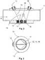
- Fig. 2 and 3shows a waveform of an acoustic signal 10 during its multiple reflection in a measuring tube 11 of a second embodiment of a flow meter according to the invention.
- the acoustic signalis emitted by a first ultrasound transducer 17, reflected on each reflection surface 12-16 of a reflector arrangement with a plurality of reflection surfaces 12-16, and then detected by a second ultrasound transducer 18.
- the deflection or drift of the acoustic signal 10 along the respective signal path, which is caused by the flow of the fluid,is compensated for.
Landscapes
- Physics & Mathematics (AREA)
- Electromagnetism (AREA)
- Fluid Mechanics (AREA)
- General Physics & Mathematics (AREA)
- Measuring Volume Flow (AREA)
Description
Translated fromGermanDie Erfindung betrifft ein Ultraschall-Durchflussmessgerät nach dem Oberbegriff des Anspruchs 1 und ein Verfahren zur Ermittlung der Fließgeschwindigkeit bzw. des Volumendurchflusses eines Fluids nach dem Oberbegriff des Anspruchs 10. Ein solches Gerät und ein solches Verfahren sind z.B. aus
Das Patent
Ein Ultraschalldurchflussmessgerät, welches nach dem Laufzeitdifferenzprinzip arbeitet, ist an sich bekannt und wird beispielsweise
Es ist daher die Aufgabe der vorliegenden Erfindung ein Ultraschallmessgerät mit geschwindigkeitskompensierter Strahlführung zu schaffen, sowie ein Verfahren, welches einer Signalschwächung durch Verwehungen entgegenwirkt.It is therefore the object of the present invention to provide an ultrasonic measuring device with speed-compensated beam guidance and a method which counteracts signal weakening by drifts.
Diese Aufgabe wird durch ein Ultraschall-Durchflussmessgerät mit den Merkmalen des Anspruchs 1 und ein Verfahren mit den Merkmalen des Anspruchs 10 gelöst.This object is achieved by an ultrasonic flow measuring device with the features of
Das erfindungsgemäße Ultraschall-Durchflussmessgerät zur Ermittlung der Fließgeschwindigkeit bzw. des Volumendurchflusses eines Fluids im Laufzeitdifferenzverfahren, insbesondere eines Gases oder einer Flüssigkeit, umfasst ein Messrohr mit einer geraden Messrohrachse; zumindest einen ersten Wandler zum Senden eines akustischen Signals, zumindest einen zweiten Wandler zum Empfangen des akustischen Signals und zumindest eine Reflexionsfläche zur Reflexion des akustischen Signals umfasst, wobei der erste Wandler und der zweite Wandler derart an der Rohrwandung des Messrohres angeordnet sind, dass sie das akustische Signal schräg oder senkrecht zur Strömungsrichtung (A) des Fluids aussenden bzw. empfangen, wobei das akustische Signal zwischen dem ersten Wandler und dem zweiten Wandler entlang eines Signalpfads verläuft, welcher eine Reflexion an der mindestens einen Reflexionsfläche umfasst, wobei erfindungsgemäß die mindestens eine Reflexionsfläche in zumindest einer Vorzugsrichtung im Messrohr konkav ausgebildet ist.The ultrasonic flow measuring device according to the invention for determining the flow velocity or the volume flow of a fluid in the transit time difference method, in particular a gas or a liquid, comprises a measuring tube with a straight measuring tube axis; comprises at least a first transducer for transmitting an acoustic signal, at least a second transducer for receiving the acoustic signal and at least one reflection surface for reflecting the acoustic signal, the first transducer and the second transducer being arranged on the tube wall of the measuring tube in such a way that they do so Send or receive the acoustic signal obliquely or perpendicular to the direction of flow (A) of the fluid, the acoustic signal running between the first transducer and the second transducer along a signal path which comprises a reflection on the at least one reflection surface, the at least one reflection surface according to the invention is concave in at least one preferred direction in the measuring tube.
Die Vorzugsrichtung kann insbesondere die axiale Richtung, also die Längsrichtung des Messrohrs umfassen.The preferred direction can in particular include the axial direction, that is to say the longitudinal direction of the measuring tube.
Bei dem akustischen Signal handelt es sich vorzugsweise um ein Ultraschallsignal.The acoustic signal is preferably an ultrasound signal.
Aufgrund der konkaven Ausbildung der Reflexionsfläche in Richtung der Messachse, werden akustische Signale, welche ansonsten auf die flache Reflexionsfläche der Innenwandung des Messrohres treffen würden, abgelenkt. Dadurch kann die Verwehung eines akustischen Signals in oder gegen die Strömungsrichtung des Fluids ausgeglichen werden und somit eine Geschwindigkeitskompensierung der Strahlenführung erreicht werden. Vorteilhafte Ausgestaltungen der Erfindung sind Gegenstand der Unteransprüche.Due to the concave design of the reflection surface in the direction of the measuring axis, acoustic signals which would otherwise hit the flat reflection surface of the inner wall of the measuring tube are deflected. As a result, the drift of an acoustic signal in or against the direction of flow of the fluid can be compensated and speed compensation of the beam guidance can thus be achieved. Advantageous embodiments of the invention are the subject of the dependent claims.
Die Reflexionsfläche ist vorzugsweise als konkaver Hohlspiegel ausgebildet.The reflection surface is preferably designed as a concave concave mirror.
Es ist besonders von Vorteil, wenn im Messrohr mehrere Reflexionsflächen zur Mehrfachreflexion des akustischen Signals angeordnet sind, so dass beispielsweise eine mittlere Fließgeschwindigkeit genauer bestimmbar ist. Mit der Zahl der Reflexionen im Messrohr steigt allerdings die Mess-Strecke bzw. die Länge des Signalpfads und damit das Ausmaß der Verwehungen. Daher ist es besonders von Vorteil, wenn eine entsprechende Geschwindigkeitskompensation durch die konkave Reflexionsfläche, insbesondere bei Mehrfachreflexion an jedem Reflexionspunkt im Messrohr erfolgt.It is particularly advantageous if a plurality of reflection surfaces for multiple reflection of the acoustic signal are arranged in the measuring tube, so that, for example, an average flow rate can be determined more precisely. However, the number of reflections in the measuring tube increases the measuring distance or the length of the signal path and thus the extent of the drifts. It is therefore particularly advantageous if the concave reflection surface, in particular in the case of multiple reflection, provides for a corresponding speed compensation at each reflection point in the measuring tube.
Für eine bessere Wartung oder auch für eine leichtere Zugänglichkeit im Defektfall ist erfindungsgemäß die Reflexionsfläche als Bauteil ausgebildet, welches lösbar in das Messrohr eingebracht ist.For better maintenance or for easier access in the event of a defect, the reflective surface is designed according to the invention as a component which is detachably introduced into the measuring tube.
Alternativ ist mindestens eine konkav ausgebildete Reflexionsfläche als Bauteil ausgebildet, welches mit dem Messrohr gefügt ist, wobei das Fügen insbesondere Schweißen, Löten oder Kleben umfasst. Dies ist aber nicht beansprucht.Alternatively, at least one concave reflection surface is designed as a component which is joined to the measuring tube, the joining particularly comprising welding, soldering or gluing. However, this is not claimed.
Alternativ ist mindestens eine konkav ausgebildete Reflexionsfläche einstückig mit dem Messrohr gebildet. Dies ist aber nicht beansprucht.Alternatively, at least one concave reflection surface is formed in one piece with the measuring tube. However, this is not claimed.
Durch das Ultraschall-Durchflussmessgerät sind gemäß einer Weiterbildung der Erfindung insbesondere auch akustische Signale bei einem Verhältnis (vF/c) einer Strömungsgeschwindigkeit vF des Fluid zu einer Geschwindigkeit c des akustischen Signals im Fluid von mehr als 0,1% in vorteilhafter Weise erfassbar. Ein derartiges Verhältnis tritt insbesondere bei Gasen oder sehr schnell fließenden Flüssigkeiten auf. Für derartig schnellfließende Fluide kann das beschriebene Ultraschallmessgerät vorteilhaft verwendet werden, ohne dass es zu einer signifikanten Schwächung des akustischen Signals kommt.According to a further development of the invention, the ultrasonic flow measuring device in particular also generates acoustic signals at a ratio (vF / c) a flow velocity vF of the fluid to a velocity c of the acoustic signal in the fluid of more than 0.1% can be detected in an advantageous manner. Such a ratio occurs particularly in the case of gases or very rapidly flowing liquids. The ultrasound measuring device described can advantageously be used for such fast-flowing fluids without the acoustic signal being significantly weakened.
Zusätzlich zur Geschwindigkeitskompensation sind gemäß einer Weiterbildung der Erfindung die akustischen Signale durch die konkave Reflexionsfläche fokussierbar. Dadurch kann die durch den Empfänger detektierte Signalintensität vorteilhaft verbessert werden.In addition to speed compensation, according to a further development of the invention, the acoustic signals can be focused through the concave reflection surface. As a result, the signal intensity detected by the receiver can advantageously be improved.
Gemäß einer Weiterbildung der Erfindung sind der erste Wandler und der zweite Wandler jeweils als Ultraschallwandler zum Erzeugen und zum Empfangen von akustischen Signalen ausgebildet.According to a development of the invention, the first transducer and the second transducer are each designed as ultrasonic transducers for generating and receiving acoustic signals.
Gemäß eine Weiterbildung der Erfindung weist das Ultraschall-Durchflussmessgerät mehrere Reflexionsflächen mit konkaver Kontur auf, wobei ein erster Krümmungsradius im Zentrum einer ersten Reflexionsfläche in einer ersten Reflexionsebene einer Reflexion eines idealisierten Signalpfads an der ersten Reflexionsfläche von einem zweiten Krümmungsradius im Zentrum einer zweiten Reflexionsfläche in einer zweiten Reflexionsebene einer Reflexion des idealisierten Signalpfads an der zweiten Reflexionsfläche abweicht, wobei der idealisierte Signalpfad jeweils geradlinig zwischen den Zentren von Sende- bzw. Empfangsflächen der Ultraschallwandler und den Zentren der Reflexionsflächen verläuft.According to a development of the invention, the ultrasound flow measuring device has a plurality of reflection surfaces with a concave contour, a first radius of curvature in the center of a first reflection surface in a first reflection plane reflecting an idealized signal path on the first reflection surface from a second radius of curvature in the center of a second reflection surface in one second reflection plane of a reflection of the idealized signal path deviates from the second reflection surface, the idealized signal path running in each case in a straight line between the centers of the transmission or reception surfaces of the ultrasonic transducers and the centers of the reflection surfaces.
Gemäß einer Weiterbildung der Erfindung weist mindestens eine Reflexionsfläche eine konkave, parabolische Kontur aufweist.According to a development of the invention, at least one reflection surface has a concave, parabolic contour.
Gemäß einer Weiterbildung der Erfindung weicht ein erster Krümmungsradius im Zentrum mindestens einer ersten Reflexionsfläche in einer ersten Reflexionsebene eines idealisierten Signalpfads einer Reflexion an der ersten Reflexionsfläche von einem zweiten Krümmungsradius im Zentrum der ersten Reflexionsfläche in einer zweiten Ebene welche senkrecht zur ersten Reflexionsebene verläuft, und in welcher die Oberflächennormale der ersten Reflexionsfläche im Zentrum der ersten Reflexionsfläche liegt, abweicht.According to a development of the invention, a first radius of curvature in the center of at least one first reflection surface in a first reflection plane of an idealized signal path of a reflection on the first reflection surface deviates from a second radius of curvature in the center of the first reflection surface in a second plane which is perpendicular to the first reflection plane, and in which deviates the surface normal of the first reflection surface in the center of the first reflection surface.
In einer Weiterbildung der Erfindung weisen mindestens zwei Reflektionsflächen voneinander abweichende Flächenmaße auf.In a development of the invention, at least two reflection surfaces have different surface dimensions.
In einer Weiterbildung der Erfindung weist mindestens eine Reflexionsfläche in einer Vorzugsrichtung eine größere Erstreckung auf als in andere Richtungen.In a development of the invention, at least one reflection surface has a greater extension in a preferred direction than in other directions.
In einer Weiterbildung der Erfindung ist mindestens eine Reflexionsfläche in Richtung der Strömung stärker ausgebildet. D.h. insbesondere, dass der Abstand der mindestens einen Reflexionsfläche zur Rohrmittelachse mit der Strömungsrichtung abnimmt.In a further development of the invention, at least one reflection surface is made stronger in the direction of the flow. That in particular that the distance of the at least one reflection surface from the pipe center axis decreases with the flow direction.
Erfindungsgemäß umfasst ein Verfahren zur Ermittlung der Fließgeschwindigkeit eines Fluids im Laufzeitdifferenzmessverfahren, insbesondere eines Gases oder einer Flüssigkeit, mittels Ultraschalldurchflussmessung in einem Messrohr mit gerader Messrohrachse, die folgenden Schritte:
- a) Aussenden zumindest eines akustischen Signals schräg oder senkrecht zur Strömungsrichtung des Fluids durch einen Sender;
- b) Reflektieren des akustischen Signals an einer oder mehreren konkaven Reflexionsflächen und
- c) Empfangen und Auswerten des akustischen Signals zur Ermittlung der Fließgeschwindigkeit des Fluids.
- a) emitting at least one acoustic signal obliquely or perpendicular to the direction of flow of the fluid through a transmitter;
- b) reflecting the acoustic signal on one or more concave reflection surfaces and
- c) receiving and evaluating the acoustic signal to determine the flow rate of the fluid.
Durch die Reflexion an einer oder mehreren konkaven Reflexionsflächen wird die Signalabschwächung durch Verwehungen des Signals im Wesentlichen kompensiert dies kann einerseits durch Änderung des Ausfallwinkels erfolgen und andererseits durch Fokussierung des akustischen Signals.The reflection at one or more concave reflection surfaces essentially compensates for the signal weakening due to drifting of the signal. This can be done on the one hand by changing the angle of reflection and on the other hand by focusing the acoustic signal.
Nachfolgend wird die Erfindung anhand der Zeichnungen näher erläutert. Sie zeigen:
- Fig. 1
- eine geschnittene Seitenansicht einer schematischen Darstellung eines erfindungsgemäßen Ultraschall-Durchflussmessgerätes bei Einfachreflexion;
- Fig. 2
- eine geschnittene Seitenansicht über einen Signalverlauf bei Mehrfachreflexion in einem Messrohr eines erfindungsgemäßen Ultraschall-Durchflussmessgerätes;
- Fig. 3
- eine Vorderansicht mit einem Signalverlauf bei Mehrfachreflexion in einem Messrohr eines erfindungsgemäßen Ultraschall-Durchflussmessgerätes; und
- Fig. 4
- eine geschnittene Seitenansicht einer schematischen Darstellung eines Ultraschall-Durchflussmessgerätes bei Einfachreflexion nach dem Stand der Technik.
- Fig. 1
- a sectional side view of a schematic representation of an ultrasonic flow meter according to the invention with single reflection;
- Fig. 2
- a sectional side view of a signal curve with multiple reflection in a measuring tube of an ultrasonic flow meter according to the invention;
- Fig. 3
- a front view with a signal curve with multiple reflection in a measuring tube of an ultrasonic flow meter according to the invention; and
- Fig. 4
- a sectional side view of a schematic representation of an ultrasonic flowmeter with single reflection according to the prior art.
Ein Laufzeitdifferenzmessverfahren zur Bestimmung von Fließgeschwindigkeiten eines Fluids ist an sich bekannt. Beim Laufzeitdifferenz-Prinzip werden die unterschiedlichen Laufzeiten von Ultraschallimpulsen relativ zur Strömungsrichtung des Fluids ausgewertet. Dabei wird die Ausbreitungsgeschwindigkeit von akustischen Signalen, insbesondere von Ultraschallwellen in einem Medium von dessen Fliessgeschwindigkeit direkt beeinflusst wird. Hierfür werden Ultraschallimpulse sowohl in wie auch entgegen der Strömung gesendet. Aus der Laufzeitdifferenz lässt sich die Fliessgeschwindigkeit und damit bei bekanntem Durchmesser des Rohrleitungsabschnitts der Volumendurchfluss bestimmen.A transit time difference measurement method for determining flow velocities of a fluid is known per se. With the transit time difference principle, the different transit times of ultrasonic pulses are evaluated relative to the direction of flow of the fluid. The rate of propagation by acoustic signals, in particular by ultrasonic waves in a medium, the flow velocity of which is directly influenced. For this purpose, ultrasonic pulses are sent both in and against the flow. From the transit time difference, the flow velocity and thus the volume flow rate can be determined if the diameter of the pipe section is known.
Dieses Ultraschallmessgerät weist ein Messrohr 6 auf. Dieses Messrohr 6 verfügt über eine Außenwandung 8 und eine Innenwandung 7. Das Messrohr 6 weist zudem einen ersten Wandler 2 auf, zum Erzeugen eines akustischen Signals 5, welcher als Ultraschallwandler ausgebildet ist, und einen zweiten Wandler 3, zur Detektion des akustischen Signals 5, welcher ebenfalls als Ultraschallwandler ausgebildet ist.This ultrasonic measuring device has a measuring
Dieses akustische Signal 5 wird in
Der zweite Wandler 3 kann ebenfalls, hier nicht dargestellt, ein akustisches Signal entgegen der Strömungsrichtung A des Fluids aussenden, welches vom ersten Wandler 2 detektiert werden kann. Aus der Laufzeitdifferenz beider Signale kann die Fließgeschwindigkeit des Fluids bzw. dessen Volumendurchfluss ermittelt werden.The
Messrohr 6 weist zudem eine Reflektoranordnung 4 mit einer Reflexionsflächen 4a auf, welche hier im konkreten Fall als konkaver Hohlspiegel ausgebildet ist. Dieser Hohlspiegel ermöglicht eine Korrektur der Verwehung des akustischen Signals, derart, dass der Einfallswinkel α des akustischen Signals 5, bezogen auf eine zur Rohrlängsachse senkrechte Ebene, einen anderen Betrag aufweist als der Ausfallswinkel β des akustischen Signals 5 nach dessen Reflexion an der Reflexionsfläche 4a.Measuring
Durch diese spezielle Reflexionsfläche 4a kann eine Verwehung des akustischen Signals 5 in Strömungsrichtung A ausgeglichen werden. Die Verwehung des akustischen Signals 5 kann sowohl in Strömungsrichtung A oder entgegen Strömungsrichtung A erfolgen. Unabhängig von der Strömungsrichtung A wird durch die spezielle Reflexionsfläche 4A ein vollständiger oder zumindest ein teilweiser Ausgleich zu der besagten Verwehung erreicht.A drift of the
Bei dem hier dargestellten gleichmäßig konkav ausgebildeten Hohlspiegel liegt die optische bzw. akustische Achse vorteilhaft an dem Punkt, bei welchem das akustische Signal 5 auftreffen würde, sofern es zu keiner Ablenkung des akustischen Signals 5 entlang des Signalpfades kommen würde, bzw. bei dem sich das im Messrohr 6 befindliche Fluid sich im Stillstand befinden würde.In the case of the uniformly concave concave mirror shown here, the optical or acoustic axis advantageously lies at the point at which the
Die Reflektoranordnung 4 mit der Reflexionsfläche 4a oder -flächen kann insbesondere als Bauteil an der Innenwandung 7 des Messrohrs 6 angebracht oder eingebracht sein. So können derartige Bauteile 4 beispielsweise durch Formenschluss mittels Schraub- oder Bajonettverbindungen lösbar in das Messrohr 6 eingebracht oder fest gefügt werden, beispielsweise durch Löten oder Schweißen. Dies ist aber nicht beansprucht.The
Das akustische Signal 5 kann schräg oder senkrecht zur Strömungsrichtung A des Fluids in das Messrohr 6 ausgesandt werden.The
Aufgrund der konkaven Krümmung der Reflexionsflächen 12 - 16 wird die Ablenkung bzw. Verwehung des akustischen Signals 10 entlang des jeweiligen Signalpfades, welche durch die Strömung des Fluids hervorgerufen wird, ausgeglichen.Due to the concave curvature of the reflection surfaces 12-16, the deflection or drift of the
Durch die in
- 11
- Ultraschalldurchfluss-MessgerätUltrasonic flow meter
- 22
- Erster Wandler (Sender)First converter (transmitter)
- 33
- Zweiter Wandler (Empfänger)Second converter (receiver)
- 44
- ReflektoranordnungReflector arrangement
- 4a4a
- ReflexionsflächeReflective surface
- 55
- akustisches Signalacoustic signal
- 66
- MessrohrMeasuring tube
- 77
- Innenwandunginner wall
- 88th
- AußenwandungOuter wall
- 1010
- akustisches Signalacoustic signal
- 1111
- MessrohrMeasuring tube
- 1212th
- RelflexionsflächeReflecting surface
- 1313
- ReflexionsflächeReflective surface
- 1414
- ReflexionsflächeReflective surface
- 1515
- ReflexionsflächeReflective surface
- 1616
- ReflexionsflächeReflective surface
- 1717
- Erster Wandler (Sender)First converter (transmitter)
- 1818th
- Zweiter Wandler (Empfänger)Second converter (receiver)
- AA
- StrömungsrichtungFlow direction
- αα
- EinfallswinkelAngle of incidence
- ββ
- AusfallswinkelAngle of reflection
Claims (15)
- Ultrasonic flowmeter (1) for determining the flow velocity or the volume flow of a fluid according to the transit time difference principle, particularly of a gas or a liquid, said flowmeter comprising a measuring tube (11) with a straight measuring tube axis, at least a first converter (2, 17) to transmit an acoustic signal (5, 10), at least a second converter (3, 18) to receive the acoustic signal (5, 10) and at least one reflection surface (4a, 12-16) to reflect the acoustic signal,
wherein the first converter (2, 17) and the second converter (3, 18) are arranged on the measuring tube wall (6, 11) in such a way that they transmit or receive the acoustic signal (5, 10) at an angle or perpendicularly to the flow direction (A) of the fluid, wherein the acoustic signal runs between the first converter and the second converter along a signal path, which comprises a reflection at the at least one reflection surface (4a, 12-16),
characterized in that
the at least one reflection surface (4a, 12-16) is designed in a concave manner in at least one preferential direction in the measuring tube,
wherein at least one reflection surface (4a, 12-16) designed in a concave manner is designed as a component (4), said component being inserted in a detachable manner in the measuring tube (5), and
wherein the converters are positioned in a first and a second opening of the measuring tube, and wherein the component is positioned in a third opening, which is physically separated from the first and second opening. - Ultrasonic flowmeter as claimed in Claim 1,characterized in that multiple reflection surfaces (12-16) are arranged in the measuring tube (6, 11) for the purpose of the multiple reflection of the acoustic signal, wherein at least one reflection surface (12-16) is designed in a concave manner.
- Ultrasonic flowmeter as claimed in Claim 2,characterized in that all the reflection surfaces (12-16) are designed in a concave manner.
- Ultrasonic flowmeter as claimed in one of the previous claims,characterized in that the acoustic signals (5, 10) can be measured with a ratio (vF/c) of a flow velocity vF of the fluid to a velocity c of the acoustic signal in the fluid of more than 0.1 %.
- Ultrasonic flowmeter as claimed in one of the previous claims,characterized in that the acoustic signals (5, 10) can be measured with a ratio (vF/c) of a flow velocity vF of the fluid to a velocity c of the acoustic signal in the fluid of more than 1 % with a signal attenuation (5, 10) of less than 20 %, particularly of less than 10 %.
- Ultrasonic flowmeter as claimed in one of the previous claims,characterized in that the first converter (2, 17) and the second converter (3, 18) are each designed as ultrasonic converters for the generation and reception of acoustic signals (5, 10).
- Ultrasonic flowmeter as claimed in one of the previous claims, which has multiple reflection surfaces with a concave contour, wherein a first curvature radius in the centre of a first reflection surface on a first reflection plane of a reflection of an idealized signal path at a first reflection surface deviates from a second curvature radius in the centre of a second reflection surface on a second reflection plane of a reflection of the idealized signal path at the second reflection surface, wherein the idealized signal path runs in a straight line between the centers of the transmission and reception surfaces of the ultrasonic converters and the centers of the reflection surfaces.
- Ultrasonic flowmeter as claimed in one of the previous claims,characterized in that at least one reflection surface has a concave parabolic contour.
- Ultrasonic flowmeter as claimed in one of the previous claims, wherein a first curvature radius in the centre of a first reflection surface on a first reflection plane of an idealized signal path of a reflection at the first reflection surface deviates from a second curvature radius in the centre of the first reflection surface on a second plane, which is perpendicular to the first reflection plane, and in which the surface normal of the first reflection surface is located in the center of the first reflection surface.
- Method to determine the flow velocity or volume flow of a fluid according to the transit time difference principle using an ultrasonic flowmeter as claimed in one of the previous claims, with ultrasonic flow measurement in a measuring tube (6, 11) with a straight measuring tube axis,characterized by the following steps:a) Transmission of at least one acoustic signal (5, 10) at an angle or perpendicular to the flow direction (A) of the fluid by a transmitter (2, 17) ;b) Reflection of the acoustic signal (5, 10) at one or more concave reflection surfaces (4a, 12-16) andc) Reception and evaluation of the acoustic signal (5, 10) to determine the flow velocity of the fluid.
- Method as claimed in Claim 10,characterized in that, as a result of the reflection of the acoustic signal (5, 10) at one or more concave reflection surfaces (4a, 12-16) the acoustic signal is deflected in such a way thatthe angle of incidence σ of the acoustic signal (5, 10) before the reflection andthe angle of reflection β of the acoustic signal (5, 10) after the reflection, in relation to the interior wall (7) of the measuring tube (6), differ from one another.
- Method as claimed in Claim 10 or 11,characterized in that the acoustic signal (5, 10) is focused as a result of the reflection of the acoustic signal (5, 10) at one or more concave reflection surfaces (4a, 12-16).
- Ultrasonic flowmeter as claimed in one of the Claims 1 to 9, wherein at least two reflection surfaces have surface dimensions that differ from one another.
- Ultrasonic flowmeter as claimed in one of the Claims 1 to 9 and 13,characterized in that at least one reflection surface has a larger extension in a preferential direction than in other directions.
- Ultrasonic flowmeter as claimed in one of the Claims 1 to 9, 13 and 14,characterized in that the reflection surfaces have a thicker design in the direction of flow, wherein, in particular, the distance of the reflection surfaces to the tube central axis decreases with the flow direction (A).
Applications Claiming Priority (2)
| Application Number | Priority Date | Filing Date | Title |
|---|---|---|---|
| DE102012101098ADE102012101098A1 (en) | 2012-02-10 | 2012-02-10 | Ultrasonic flowmeter and method for determining the flow rate or volumetric flow of a fluid |
| PCT/EP2013/051645WO2013117457A1 (en) | 2012-02-10 | 2013-01-29 | Ultrasonic flowmeter and method for determining the flow speed and/or the volumetric flow of a fluid |
Publications (2)
| Publication Number | Publication Date |
|---|---|
| EP2812659A1 EP2812659A1 (en) | 2014-12-17 |
| EP2812659B1true EP2812659B1 (en) | 2020-03-04 |
Family
ID=47683701
Family Applications (1)
| Application Number | Title | Priority Date | Filing Date |
|---|---|---|---|
| EP13703544.0AActiveEP2812659B1 (en) | 2012-02-10 | 2013-01-29 | Ultrasonic flowmeter and method for determining the flow speed and/or the volumetric flow of a fluid |
Country Status (4)
| Country | Link |
|---|---|
| US (1) | US9335193B2 (en) |
| EP (1) | EP2812659B1 (en) |
| DE (1) | DE102012101098A1 (en) |
| WO (1) | WO2013117457A1 (en) |
Families Citing this family (8)
| Publication number | Priority date | Publication date | Assignee | Title |
|---|---|---|---|---|
| DE102013105407A1 (en) | 2013-05-27 | 2014-11-27 | Endress + Hauser Flowtec Ag | Device for determining and / or monitoring the volume and / or mass flow of a medium |
| DE102014118187A1 (en)* | 2014-12-09 | 2016-06-09 | Endress + Hauser Flowtec Ag | Ultrasonic flowmeter |
| US10557732B2 (en)* | 2017-12-07 | 2020-02-11 | Cameron International Corporation | Flowmeters and methods of manufacture |
| FR3080683B1 (en)* | 2018-04-30 | 2023-03-17 | Buerkert Werke Gmbh & Co Kg | FLUID MEASURING MEANS |
| EP3588017A1 (en) | 2018-06-27 | 2020-01-01 | Sensus Spectrum LLC | Ultrasound measuring device |
| DE102019121542A1 (en) | 2019-08-09 | 2021-02-11 | Sensus Spectrum Llc | Measuring device for determining the flow rate of a fluid flowing through a pipe section |
| US20230228602A1 (en)* | 2022-01-19 | 2023-07-20 | International Environmental Corporation | Energy metering system for a fan coil |
| IT202200008975A1 (en)* | 2022-05-03 | 2023-11-03 | Pietro Fiorentini Spa | Improved device for measuring a fluid, preferably a gas. |
Family Cites Families (21)
| Publication number | Priority date | Publication date | Assignee | Title |
|---|---|---|---|---|
| US4754650A (en)* | 1983-07-29 | 1988-07-05 | Panametrics, Inc. | Apparatus and methods for measuring fluid flow parameters |
| EP0392294A1 (en)* | 1989-04-13 | 1990-10-17 | Siemens Aktiengesellschaft | Fluid flowmeter for measuring ultrasound transit times |
| DE4010148A1 (en)* | 1990-03-29 | 1991-10-02 | Siemens Ag | IMPROVEMENT FOR AN ULTRASONIC GAS / LIQUID FLOW METER |
| GB9119742D0 (en)* | 1991-09-16 | 1991-10-30 | British Gas Plc | Measurement system |
| DE4336370C1 (en)* | 1993-10-25 | 1995-02-02 | Siemens Ag | Device for flow measurement |
| DE4336368C2 (en)* | 1993-10-25 | 1995-08-03 | Siemens Ag | Flow measuring device |
| FR2724016B1 (en)* | 1994-08-23 | 1996-10-25 | Schlumberger Ind Sa | DEVICE FOR ULTRASONIC MEASUREMENT OF A VOLUME QUANTITY OF A FLUID WITH IMPROVED ACOUSTIC PROPERTIES |
| DK171569B1 (en)* | 1995-01-31 | 1997-01-13 | Danfoss As | Ultrasonic flow meter "W" |
| GB2318414B (en)* | 1996-10-19 | 2001-02-14 | Univ Cranfield | Improvements relating to flow measurement |
| JP2000304583A (en)* | 1999-04-23 | 2000-11-02 | Kaijo Corp | Measurement part of ultrasonic flowmeter |
| SI20391A (en)* | 1999-09-06 | 2001-04-30 | Iskraemeco Merjenje In Upravljanje Energije D.D. | Measurement tube of ultrasonic instrument for measuring volumetric fluid throughput |
| DE10120355A1 (en)* | 2001-04-26 | 2002-10-31 | Elster Gmbh | Ultrasonic flow measurement of fluids such as natural gas, has acoustic transceivers that direct divergent beams of sound waves to sections of the pipe shaped to form parabolic reflectors |
| US20040129088A1 (en) | 2002-12-30 | 2004-07-08 | D.C. Tigwell & Associates | Single-body dual-chip orthogonal sensing transit-time flow device using a parabolic reflecting surface |
| DE102004013251A1 (en)* | 2004-03-18 | 2005-10-06 | Robert Bosch Gmbh | Ultrasonic flow sensor with transducer array and reflection surface |
| DE102004060062A1 (en) | 2004-12-14 | 2006-06-29 | Robert Bosch Gmbh | Ultrasonic measuring device |
| DE102004060064B4 (en)* | 2004-12-14 | 2016-10-20 | Robert Bosch Gmbh | Ultrasonic flow meter with turbulators |
| DE102005007241B4 (en)* | 2005-02-17 | 2007-05-31 | Hydrometer Gmbh | Flowmeter |
| DE102005038599A1 (en)* | 2005-08-16 | 2007-02-22 | Robert Bosch Gmbh | Ultrasonic measuring unit with integrated moisture detection |
| DE102006023478A1 (en) | 2006-05-18 | 2007-11-22 | Siemens Ag | Flow sensor and flow channel for receiving the flow sensor |
| DE102006023479A1 (en) | 2006-05-18 | 2007-11-22 | Siemens Ag | Flow channel for receiving the flow sensor |
| DE102011079250A1 (en) | 2011-07-15 | 2013-01-17 | Endress + Hauser Flowtec Ag | Ultrasonic flowmeter |
- 2012
- 2012-02-10DEDE102012101098Apatent/DE102012101098A1/ennot_activeCeased
- 2013
- 2013-01-29USUS14/377,033patent/US9335193B2/enactiveActive
- 2013-01-29EPEP13703544.0Apatent/EP2812659B1/enactiveActive
- 2013-01-29WOPCT/EP2013/051645patent/WO2013117457A1/enactiveApplication Filing
Non-Patent Citations (1)
| Title |
|---|
| None* |
Also Published As
| Publication number | Publication date |
|---|---|
| US20150000422A1 (en) | 2015-01-01 |
| WO2013117457A1 (en) | 2013-08-15 |
| DE102012101098A1 (en) | 2013-08-14 |
| US9335193B2 (en) | 2016-05-10 |
| EP2812659A1 (en) | 2014-12-17 |
Similar Documents
| Publication | Publication Date | Title |
|---|---|---|
| EP2812659B1 (en) | Ultrasonic flowmeter and method for determining the flow speed and/or the volumetric flow of a fluid | |
| DE102011052670B4 (en) | Ultrasonic transducer device | |
| EP3404372B1 (en) | Ultrasound flowmeter | |
| DE102013105922A1 (en) | Ultrasonic flowmeter | |
| WO2007104708A2 (en) | Device for determining and/or monitoring the volume or mass flow rate of a medium in a pipe conduit | |
| WO2011045107A1 (en) | Ultrasonic flow sensor for detecting a flow of a fluid medium | |
| WO1991014925A1 (en) | Improvement to gas/liquid ultrasonic flowmeter | |
| EP1955019B1 (en) | Ultrasonic measuring apparatus for determining and/or monitoring the volume or mass flow rate of a medium through a pipe | |
| EP2370793A1 (en) | Measuring system for determining and/or monitoring the flow rate of a measured medium through the measuring tube using ultrasound | |
| DE102007062913A1 (en) | Ultrasonic transducer i.e. clamp-on ultrasonic transducer, for use in process and automation technology, has coupling element, where exit of ultrasonic signal from coupling element in signal path is registered by piezo-electric element | |
| DE102014118187A1 (en) | Ultrasonic flowmeter | |
| DE102007011547B4 (en) | Fluidzählanordnung | |
| EP4182703B1 (en) | Flowmeter and method for measuring the flow of a fluid | |
| EP1762841A1 (en) | Method and device for ultrasonic testing of a workpiece having an uneven surface | |
| EP0451355B1 (en) | Measuring device for determining the flow of a flowing fluid | |
| EP3343185B1 (en) | Ultrasound flow measuring device and method for measuring the flow | |
| EP3273205B1 (en) | Method and assembly for ultrasound clamp on flow measurement and body for realizing the measurement | |
| DE102010063789A1 (en) | Ultrasonic flowmeter | |
| EP0650035B1 (en) | Flow meter | |
| DE102016115199B4 (en) | Ultrasonic sensor for determining or monitoring a process variable of a medium in automation technology | |
| DE3911408A1 (en) | Measuring tube for ultrasonic flow measurements | |
| WO2002045074A1 (en) | Ultrasonic transducer and ultrasonic flowmeter | |
| EP1096236A2 (en) | Ultrasonic flowmeter for fluids | |
| WO2005031369A2 (en) | Ultrasound sensor and method for measuring flow rate | |
| DE4341542C2 (en) | Flow measurement device |
Legal Events
| Date | Code | Title | Description |
|---|---|---|---|
| PUAI | Public reference made under article 153(3) epc to a published international application that has entered the european phase | Free format text:ORIGINAL CODE: 0009012 | |
| 17P | Request for examination filed | Effective date:20140708 | |
| AK | Designated contracting states | Kind code of ref document:A1 Designated state(s):AL AT BE BG CH CY CZ DE DK EE ES FI FR GB GR HR HU IE IS IT LI LT LU LV MC MK MT NL NO PL PT RO RS SE SI SK SM TR | |
| AX | Request for extension of the european patent | Extension state:BA ME | |
| DAX | Request for extension of the european patent (deleted) | ||
| GRAP | Despatch of communication of intention to grant a patent | Free format text:ORIGINAL CODE: EPIDOSNIGR1 | |
| STAA | Information on the status of an ep patent application or granted ep patent | Free format text:STATUS: GRANT OF PATENT IS INTENDED | |
| INTG | Intention to grant announced | Effective date:20190927 | |
| GRAS | Grant fee paid | Free format text:ORIGINAL CODE: EPIDOSNIGR3 | |
| GRAA | (expected) grant | Free format text:ORIGINAL CODE: 0009210 | |
| STAA | Information on the status of an ep patent application or granted ep patent | Free format text:STATUS: THE PATENT HAS BEEN GRANTED | |
| AK | Designated contracting states | Kind code of ref document:B1 Designated state(s):AL AT BE BG CH CY CZ DE DK EE ES FI FR GB GR HR HU IE IS IT LI LT LU LV MC MK MT NL NO PL PT RO RS SE SI SK SM TR | |
| REG | Reference to a national code | Ref country code:GB Ref legal event code:FG4D Free format text:NOT ENGLISH | |
| REG | Reference to a national code | Ref country code:CH Ref legal event code:EP | |
| REG | Reference to a national code | Ref country code:AT Ref legal event code:REF Ref document number:1240912 Country of ref document:AT Kind code of ref document:T Effective date:20200315 | |
| REG | Reference to a national code | Ref country code:DE Ref legal event code:R096 Ref document number:502013014384 Country of ref document:DE | |
| REG | Reference to a national code | Ref country code:IE Ref legal event code:FG4D Free format text:LANGUAGE OF EP DOCUMENT: GERMAN | |
| PG25 | Lapsed in a contracting state [announced via postgrant information from national office to epo] | Ref country code:RS Free format text:LAPSE BECAUSE OF FAILURE TO SUBMIT A TRANSLATION OF THE DESCRIPTION OR TO PAY THE FEE WITHIN THE PRESCRIBED TIME-LIMIT Effective date:20200304 Ref country code:FI Free format text:LAPSE BECAUSE OF FAILURE TO SUBMIT A TRANSLATION OF THE DESCRIPTION OR TO PAY THE FEE WITHIN THE PRESCRIBED TIME-LIMIT Effective date:20200304 Ref country code:NO Free format text:LAPSE BECAUSE OF FAILURE TO SUBMIT A TRANSLATION OF THE DESCRIPTION OR TO PAY THE FEE WITHIN THE PRESCRIBED TIME-LIMIT Effective date:20200604 | |
| REG | Reference to a national code | Ref country code:NL Ref legal event code:MP Effective date:20200304 | |
| PG25 | Lapsed in a contracting state [announced via postgrant information from national office to epo] | Ref country code:BG Free format text:LAPSE BECAUSE OF FAILURE TO SUBMIT A TRANSLATION OF THE DESCRIPTION OR TO PAY THE FEE WITHIN THE PRESCRIBED TIME-LIMIT Effective date:20200604 Ref country code:HR Free format text:LAPSE BECAUSE OF FAILURE TO SUBMIT A TRANSLATION OF THE DESCRIPTION OR TO PAY THE FEE WITHIN THE PRESCRIBED TIME-LIMIT Effective date:20200304 Ref country code:GR Free format text:LAPSE BECAUSE OF FAILURE TO SUBMIT A TRANSLATION OF THE DESCRIPTION OR TO PAY THE FEE WITHIN THE PRESCRIBED TIME-LIMIT Effective date:20200605 Ref country code:LV Free format text:LAPSE BECAUSE OF FAILURE TO SUBMIT A TRANSLATION OF THE DESCRIPTION OR TO PAY THE FEE WITHIN THE PRESCRIBED TIME-LIMIT Effective date:20200304 Ref country code:SE Free format text:LAPSE BECAUSE OF FAILURE TO SUBMIT A TRANSLATION OF THE DESCRIPTION OR TO PAY THE FEE WITHIN THE PRESCRIBED TIME-LIMIT Effective date:20200304 | |
| REG | Reference to a national code | Ref country code:LT Ref legal event code:MG4D | |
| PG25 | Lapsed in a contracting state [announced via postgrant information from national office to epo] | Ref country code:NL Free format text:LAPSE BECAUSE OF FAILURE TO SUBMIT A TRANSLATION OF THE DESCRIPTION OR TO PAY THE FEE WITHIN THE PRESCRIBED TIME-LIMIT Effective date:20200304 | |
| PG25 | Lapsed in a contracting state [announced via postgrant information from national office to epo] | Ref country code:SK Free format text:LAPSE BECAUSE OF FAILURE TO SUBMIT A TRANSLATION OF THE DESCRIPTION OR TO PAY THE FEE WITHIN THE PRESCRIBED TIME-LIMIT Effective date:20200304 Ref country code:EE Free format text:LAPSE BECAUSE OF FAILURE TO SUBMIT A TRANSLATION OF THE DESCRIPTION OR TO PAY THE FEE WITHIN THE PRESCRIBED TIME-LIMIT Effective date:20200304 Ref country code:SM Free format text:LAPSE BECAUSE OF FAILURE TO SUBMIT A TRANSLATION OF THE DESCRIPTION OR TO PAY THE FEE WITHIN THE PRESCRIBED TIME-LIMIT Effective date:20200304 Ref country code:LT Free format text:LAPSE BECAUSE OF FAILURE TO SUBMIT A TRANSLATION OF THE DESCRIPTION OR TO PAY THE FEE WITHIN THE PRESCRIBED TIME-LIMIT Effective date:20200304 Ref country code:ES Free format text:LAPSE BECAUSE OF FAILURE TO SUBMIT A TRANSLATION OF THE DESCRIPTION OR TO PAY THE FEE WITHIN THE PRESCRIBED TIME-LIMIT Effective date:20200304 Ref country code:CZ Free format text:LAPSE BECAUSE OF FAILURE TO SUBMIT A TRANSLATION OF THE DESCRIPTION OR TO PAY THE FEE WITHIN THE PRESCRIBED TIME-LIMIT Effective date:20200304 Ref country code:RO Free format text:LAPSE BECAUSE OF FAILURE TO SUBMIT A TRANSLATION OF THE DESCRIPTION OR TO PAY THE FEE WITHIN THE PRESCRIBED TIME-LIMIT Effective date:20200304 Ref country code:PT Free format text:LAPSE BECAUSE OF FAILURE TO SUBMIT A TRANSLATION OF THE DESCRIPTION OR TO PAY THE FEE WITHIN THE PRESCRIBED TIME-LIMIT Effective date:20200729 Ref country code:IS Free format text:LAPSE BECAUSE OF FAILURE TO SUBMIT A TRANSLATION OF THE DESCRIPTION OR TO PAY THE FEE WITHIN THE PRESCRIBED TIME-LIMIT Effective date:20200704 | |
| REG | Reference to a national code | Ref country code:DE Ref legal event code:R097 Ref document number:502013014384 Country of ref document:DE | |
| PLBE | No opposition filed within time limit | Free format text:ORIGINAL CODE: 0009261 | |
| STAA | Information on the status of an ep patent application or granted ep patent | Free format text:STATUS: NO OPPOSITION FILED WITHIN TIME LIMIT | |
| PG25 | Lapsed in a contracting state [announced via postgrant information from national office to epo] | Ref country code:DK Free format text:LAPSE BECAUSE OF FAILURE TO SUBMIT A TRANSLATION OF THE DESCRIPTION OR TO PAY THE FEE WITHIN THE PRESCRIBED TIME-LIMIT Effective date:20200304 Ref country code:IT Free format text:LAPSE BECAUSE OF FAILURE TO SUBMIT A TRANSLATION OF THE DESCRIPTION OR TO PAY THE FEE WITHIN THE PRESCRIBED TIME-LIMIT Effective date:20200304 | |
| 26N | No opposition filed | Effective date:20201207 | |
| PG25 | Lapsed in a contracting state [announced via postgrant information from national office to epo] | Ref country code:PL Free format text:LAPSE BECAUSE OF FAILURE TO SUBMIT A TRANSLATION OF THE DESCRIPTION OR TO PAY THE FEE WITHIN THE PRESCRIBED TIME-LIMIT Effective date:20200304 Ref country code:SI Free format text:LAPSE BECAUSE OF FAILURE TO SUBMIT A TRANSLATION OF THE DESCRIPTION OR TO PAY THE FEE WITHIN THE PRESCRIBED TIME-LIMIT Effective date:20200304 | |
| PG25 | Lapsed in a contracting state [announced via postgrant information from national office to epo] | Ref country code:MC Free format text:LAPSE BECAUSE OF FAILURE TO SUBMIT A TRANSLATION OF THE DESCRIPTION OR TO PAY THE FEE WITHIN THE PRESCRIBED TIME-LIMIT Effective date:20200304 | |
| REG | Reference to a national code | Ref country code:CH Ref legal event code:PL | |
| GBPC | Gb: european patent ceased through non-payment of renewal fee | Effective date:20210129 | |
| PG25 | Lapsed in a contracting state [announced via postgrant information from national office to epo] | Ref country code:LU Free format text:LAPSE BECAUSE OF NON-PAYMENT OF DUE FEES Effective date:20210129 | |
| REG | Reference to a national code | Ref country code:BE Ref legal event code:MM Effective date:20210131 | |
| PG25 | Lapsed in a contracting state [announced via postgrant information from national office to epo] | Ref country code:FR Free format text:LAPSE BECAUSE OF NON-PAYMENT OF DUE FEES Effective date:20210131 | |
| PG25 | Lapsed in a contracting state [announced via postgrant information from national office to epo] | Ref country code:LI Free format text:LAPSE BECAUSE OF NON-PAYMENT OF DUE FEES Effective date:20210131 Ref country code:GB Free format text:LAPSE BECAUSE OF NON-PAYMENT OF DUE FEES Effective date:20210129 Ref country code:CH Free format text:LAPSE BECAUSE OF NON-PAYMENT OF DUE FEES Effective date:20210131 | |
| PG25 | Lapsed in a contracting state [announced via postgrant information from national office to epo] | Ref country code:IE Free format text:LAPSE BECAUSE OF NON-PAYMENT OF DUE FEES Effective date:20210129 | |
| REG | Reference to a national code | Ref country code:AT Ref legal event code:MM01 Ref document number:1240912 Country of ref document:AT Kind code of ref document:T Effective date:20210129 | |
| PG25 | Lapsed in a contracting state [announced via postgrant information from national office to epo] | Ref country code:AT Free format text:LAPSE BECAUSE OF NON-PAYMENT OF DUE FEES Effective date:20210129 | |
| PG25 | Lapsed in a contracting state [announced via postgrant information from national office to epo] | Ref country code:BE Free format text:LAPSE BECAUSE OF NON-PAYMENT OF DUE FEES Effective date:20210131 | |
| PG25 | Lapsed in a contracting state [announced via postgrant information from national office to epo] | Ref country code:HU Free format text:LAPSE BECAUSE OF FAILURE TO SUBMIT A TRANSLATION OF THE DESCRIPTION OR TO PAY THE FEE WITHIN THE PRESCRIBED TIME-LIMIT; INVALID AB INITIO Effective date:20130129 | |
| PG25 | Lapsed in a contracting state [announced via postgrant information from national office to epo] | Ref country code:CY Free format text:LAPSE BECAUSE OF FAILURE TO SUBMIT A TRANSLATION OF THE DESCRIPTION OR TO PAY THE FEE WITHIN THE PRESCRIBED TIME-LIMIT Effective date:20200304 | |
| P01 | Opt-out of the competence of the unified patent court (upc) registered | Effective date:20230601 | |
| PG25 | Lapsed in a contracting state [announced via postgrant information from national office to epo] | Ref country code:MK Free format text:LAPSE BECAUSE OF FAILURE TO SUBMIT A TRANSLATION OF THE DESCRIPTION OR TO PAY THE FEE WITHIN THE PRESCRIBED TIME-LIMIT Effective date:20200304 | |
| PG25 | Lapsed in a contracting state [announced via postgrant information from national office to epo] | Ref country code:MT Free format text:LAPSE BECAUSE OF FAILURE TO SUBMIT A TRANSLATION OF THE DESCRIPTION OR TO PAY THE FEE WITHIN THE PRESCRIBED TIME-LIMIT Effective date:20200304 | |
| PGFP | Annual fee paid to national office [announced via postgrant information from national office to epo] | Ref country code:DE Payment date:20250121 Year of fee payment:13 |