EP2811678B1 - A network apparatus, a memory medium and a method of operating the same with polling - Google Patents
A network apparatus, a memory medium and a method of operating the same with pollingDownload PDFInfo
- Publication number
- EP2811678B1 EP2811678B1EP14178276.3AEP14178276AEP2811678B1EP 2811678 B1EP2811678 B1EP 2811678B1EP 14178276 AEP14178276 AEP 14178276AEP 2811678 B1EP2811678 B1EP 2811678B1
- Authority
- EP
- European Patent Office
- Prior art keywords
- data
- polling
- polling interval
- user equipment
- network apparatus
- Prior art date
- Legal status (The legal status is an assumption and is not a legal conclusion. Google has not performed a legal analysis and makes no representation as to the accuracy of the status listed.)
- Expired - Lifetime
Links
- 238000000034methodMethods0.000titleclaimsdescription17
- 230000005540biological transmissionEffects0.000claimsdescription43
- 230000001413cellular effectEffects0.000claimsdescription8
- 238000004891communicationMethods0.000claimsdescription8
- 238000012546transferMethods0.000description10
- 239000000872bufferSubstances0.000description6
- 230000007246mechanismEffects0.000description5
- 230000011664signalingEffects0.000description4
- 230000004044responseEffects0.000description3
- 241000377350PuanSpecies0.000description2
- 230000006978adaptationEffects0.000description2
- 238000010586diagramMethods0.000description2
- 230000006870functionEffects0.000description2
- 230000002452interceptive effectEffects0.000description2
- 238000010295mobile communicationMethods0.000description2
- 238000004904shorteningMethods0.000description2
- 108700026140MAC combinationProteins0.000description1
- 101710116852Molybdenum cofactor sulfurase 1Proteins0.000description1
- 101100465000Mus musculus Prag1 geneProteins0.000description1
- 230000004913activationEffects0.000description1
- 230000003139buffering effectEffects0.000description1
- 230000008859changeEffects0.000description1
- 238000012790confirmationMethods0.000description1
- 238000012937correctionMethods0.000description1
- 230000003247decreasing effectEffects0.000description1
- 238000013461designMethods0.000description1
- 230000000694effectsEffects0.000description1
- 238000005516engineering processMethods0.000description1
- 238000000605extractionMethods0.000description1
- 230000000977initiatory effectEffects0.000description1
- 238000003780insertionMethods0.000description1
- 230000037431insertionEffects0.000description1
- 239000012464large bufferSubstances0.000description1
- 238000007726management methodMethods0.000description1
- 238000005259measurementMethods0.000description1
- 238000012986modificationMethods0.000description1
- 230000004048modificationEffects0.000description1
- 238000005457optimizationMethods0.000description1
- 230000008520organizationEffects0.000description1
- 238000013439planningMethods0.000description1
- 230000003334potential effectEffects0.000description1
- 238000013468resource allocationMethods0.000description1
- 230000011218segmentationEffects0.000description1
- 238000001228spectrumMethods0.000description1
- 230000001360synchronised effectEffects0.000description1
- 230000032258transportEffects0.000description1
Images


Classifications
- H—ELECTRICITY
- H04—ELECTRIC COMMUNICATION TECHNIQUE
- H04J—MULTIPLEX COMMUNICATION
- H04J3/00—Time-division multiplex systems
- H04J3/16—Time-division multiplex systems in which the time allocation to individual channels within a transmission cycle is variable, e.g. to accommodate varying complexity of signals, to vary number of channels transmitted
- H—ELECTRICITY
- H04—ELECTRIC COMMUNICATION TECHNIQUE
- H04L—TRANSMISSION OF DIGITAL INFORMATION, e.g. TELEGRAPHIC COMMUNICATION
- H04L1/00—Arrangements for detecting or preventing errors in the information received
- H04L1/12—Arrangements for detecting or preventing errors in the information received by using return channel
- H04L1/16—Arrangements for detecting or preventing errors in the information received by using return channel in which the return channel carries supervisory signals, e.g. repetition request signals
- H04L1/1607—Details of the supervisory signal
- H04L1/1685—Details of the supervisory signal the supervisory signal being transmitted in response to a specific request, e.g. to a polling signal
- H—ELECTRICITY
- H04—ELECTRIC COMMUNICATION TECHNIQUE
- H04L—TRANSMISSION OF DIGITAL INFORMATION, e.g. TELEGRAPHIC COMMUNICATION
- H04L47/00—Traffic control in data switching networks
- H04L47/10—Flow control; Congestion control
- H04L47/24—Traffic characterised by specific attributes, e.g. priority or QoS
- H—ELECTRICITY
- H04—ELECTRIC COMMUNICATION TECHNIQUE
- H04W—WIRELESS COMMUNICATION NETWORKS
- H04W74/00—Wireless channel access
- H04W74/04—Scheduled access
- H04W74/06—Scheduled access using polling
Definitions
- the present inventionrelates to wireless telecommunication networks, especially cellular wireless telecommunications networks as well as satellite systems, wireless Local Area Networks (LAN) and Metropolitan Area Networks (MAN) and network elements for use therewith. It is particularly relevant to such telecommunication systems which have been optimized for packet data transmission.
- LANLocal Area Networks
- MANMetropolitan Area Networks
- GPRSGeneral Packet Radio Service
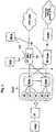
- Fig. 1A GPRS architecture proposed by ETSI in Technical Specification 3.6 is shown in Fig. 1 .
- a conventional GSM mobile telephone system for full duplex voice communicationscomprising a Mobile Switching Centre (MSC) a Base Station System (BSS) usually including a Base Station Controller (BSC) and a Base Transceiver Station (BTS), and a mobile terminal (MT) and a Home Location Register (HLR).
- MSCMobile Switching Centre
- BSCBase Station Controller
- BTSBase Transceiver Station
- HLRHome Location Register
- SMSShort Message Service
- SMS-GMSCSMS Gateway Mobile Switching Centre
- SM-SCShort Message Service Centre
- Faxis dealt with as in an ordinary telephone system, e.g. via suitable modems and an Interworking Function (IWF) fax data is transmitted via circuit switching.
- IWFInterworking Function
- GPRSadds two new nodes to such a system, namely the Serving GPRS Support Node (SGSN) and the Gateway GPRS Support node (GGSN), both of which may be seen as routers.
- the SGSNcontains the identity of MT in its routing tables which are inserted when the MT registers with the network.
- the GGSNis connected to other data carrying networks, for example a Packet Data network (PDN), for the receipt and transmission of packets of data.
- PDNPacket Data network
- the above hybrid systemmay be adapted to a Third Generation Mobile Telephone system such as the UMTS system as shown schematically in Fig. 2 . Further details of such an implementation may be found in the book by Ojanper ⁇ and Prasad, "Wideband CDMA for Third Generation Mobile Communications", Artech House Publishers, 1998 .
- the Radio Access Networkprovides the network-side equipment for communicating with the MT.
- a GPRS SGSN and a UMTS MSCare provided in parallel between the RAN and the relevant network, i.e. or a PDN or a Public Service Telephone Network (PSTN), respectively.
- PSTNPublic Service Telephone Network
- the GPRS standardsprovide, especially in ETSI standard 3GPP TS 08.18 (e.g. V8.10.0 (2002-05 )), possibilities to dynamically adjust the Quality of Service (QoS) for data transmitted over the air interface.
- QoSQuality of Service
- GPRSprovides a connectionless support for data transmission.
- a circuit switched radio resource allocationis used.
- the networks attached to the GGSNmay operate in a completely connectionless way, the transmission of the data packets across the air interface makes use of conventional timeslot and frame management.
- a packet handleris required which prepares the packets for transmission in frames across the air interface and receives the frames from the air interface and prepares them for transmission to the data network.
- This unitmay be called a Packet Control Unit (PCU) and may be placed at several alternative positions, e.g.
- PCUPacket Control Unit
- BTSBase Transceiver Station
- BSCBase Station Controller
- SGSNServing GPRS Support Node
- the PCUmay be assigned to some part of the BSS - the base station system.
- frame relaywill be used between the PCU and the SGSN.
- a user equipmentsuch as a mobile terminal (MT) or mobile phone first performs a GPRS attachment.
- This operationestablishes a logical link between the UE and the SGSN, and makes the UE available for SMS (Short Message Services) over GPRS, paging via SGSN, and notification of incoming GPRS data.
- SMSShort Message Services
- the authentication of the useris carried out by the SGSN in the GPRS attachment procedure.
- the UEactivates the packet data address wanted to be used, by requesting a PDP activation procedure (Packet Data Protocol).
- PDP activation procedurePacket Data Protocol
- a PDP contextis created in the UE, the GGSN and the SGSN.
- the packet data protocol contextdefines different data transmission parameters, such as the PDP type (e.g. X.25 or IP), the PDP address (e.g. X.121 address), the quality of service (QoS) and the NSAPI (Network Service Access Point Identifier).
- PDP typee.g. X.25 or IP
- PDP addresse.g. X.121 address
- QoSquality of service
- NSAPINetwork Service Access Point Identifier
- the UEactivates the PDP context with a specific message comprising the TLLI (Temporary logic link Identity), an Activate PDP Context Request, in which it gives information on the PDP type, the PDP address, the required QoS and the NSAPI, and optionally the access point name (APN).
- TLLITemporal logic link Identity
- APNaccess point name
- the SGSNprovides the TLLI which identifies the UE.
- a data requestis initiated by a mobile terminal (MT) using an access control channel, e.g. a Random Access Channel RACH.
- an access control channele.g. a Random Access Channel RACH.
- RACHRandom Access Channel
- a MThas some data to send it makes an Uplink Radio Connection Establishment Request specifying how much data is to be sent.
- the RANreplies with a confirmation message that the uplink radio link is provided and gives details of when and how the MT is to transmit, e.g. which timeslot and how much of the timeslot can be used.
- the datais transmitted by the MT on a traffic channel and the RAN disconnects the radio link after all data has been transmitted successfully.
- the data received by the RANis forwarded to the SGSN and from there to the GGSN which removes any headers used for transporting the data up to this point and transfers the data to the relevant PDN, e.g. via the Internet to a remote server.
- the answer to the dataarrives from the remote site, e.g. a service provider's server on the Internet.
- a downlink radio connectionis set up by the RAN via a control channel and the answer data transferred via a traffic channel. After transfer the radio connection is released once again.
- Fig. 4shows a similar message scheme when the initiating message is downlink. Again, the downlink and uplink transfers are not coupled so that the downlink radio connection is released at the end of the downlink transmission and before the answering uplink transmission.
- a known problem with such as schemeis setting an optimum time interval for receipt of an ACK message before the data is resent. Too short a time can result in data being resent frequently when an ACK message is still going to be received and would have stopped the resend.
- US 6,289,224proposes a scheme in which the length of time for an outbound communication is determined and this is transmitted to the transmitting device so that the timer can be started.
- This known techniquerelies on the fact that the type of data to be sent is sensibly constant.
- the data rates and answer frequenciescan be very varied and the known scheme is not optimal in all circumstances.
- Document US 2002/0108082discloses a receiving entity that when receives a polling request transmits an acknowledgement message containing the reception status of a plurality of data blocks.
- Document US 4,763,323discloses a communication system to control access to the communication channel via a polling priority scheme. After a large block is transmitted, the receiving nonmaster station responds to the master node when polled with a short digital message block indicating error free receipt or a short digital message block requesting retransmission.
- the present inventionwill mainly be described with reference to cellular mobile telephone systems but the present invention is not limited thereto.
- the present inventionmay be advantageously used in wireless local area networks (LAN) or Metropolitan Access Networks particularly when there is an asymmetrical flow of data.
- LANwireless local area networks
- Various types of wireless LANhave been standardized or are in general use, e.g. the standards IEEE 802.11, IEEE 802.11HR (Spread Spectrum) and systems based on DECT, BlueTooth, HIPERLAN, Diffuse or point-to-point infrared.
- Wireless LAN'sare discussed in detail in " Wireless LAN's" by Jim Geier, Macmillan Technical Publishing, 1999 .
- the sharing of a data channel by multiple user terminalsmay include for instance sharing a code in a CDMA system or sharing a frequency in a Frequency Division Multiple Access system.
- Examples of wireless communication networks with support for packet data transfer to the wireless terminal of a mobile userare PDC-P networks (Pacific Digital Cellular), which in Japan provides the existing I-mode service, GSM networks (Global System for Mobile Communications) providing GPRS services (General Packet Radio Service), particularly in Europe and systems using radio networks based on EDGE technology (Enhanced Data Rates for GSM and TDMA/136 Evolution).
- PDC-P networksPacific Digital Cellular
- GSM networksGlobal System for Mobile Communications
- GPRS servicesGeneral Packet Radio Service
- the present inventionwill mainly be described with respect to a cellular mobile telephone system but the present invention may find advantageous use in a Public Mobile Radio (PMR) system.
- PMRPublic Mobile Radio
- each base station 20is supervised by a base station controller 21 or BSC by way of an interface called Abis.
- the BSSfurther comprises a packet control unit or PCU 22.
- the present inventiondoes not require the location of the PCU 22 to be within the BSS.
- the present inventionis generally applicable whether the data source consisting of the PCU 22 is remote from the sending stations consisting of the BTS's 20 or not.
- the BTU 20can communicate with one or more user equipments UE 10.
- the UE 10may be any suitable communicating device whether mobile or stationary, e.g.
- the PCU 22is situated between the BSC 21, with which it communicates via an interface called AGPRS, and the SGSN 5, with which it communicates via the interface Gb.
- the SGSN 5is linked to the BSS by way of an interface called Gb, and the GGSN serves as a gateway with external packet transmission networks (PDN), such as the Internet, for example.
- PDNpacket transmission networks
- the Gb interfaceis of asynchronous type.
- a protocol stackis shown in Fig. 6 . It is typically based on the frame relay (FR) protocol, as well as on a protocol called BSSGP (BSS GPRS Protocol) which transports routing and quality-of-service information between the BSS and the SGSN.
- BSSGPBSS GPRS Protocol
- a Gb interface controllerprovides the physical link with the SGSN, as well as carrying out the procedures specific to the FR and BSSGP protocols.
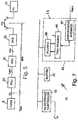
- a schematic PCU 22is shown in Fig. 7 .
- the links between the PCU 22 and the BTSs 20 via the AGPRS interfaceare of synchronous type and hence packets arriving from the asynchronous Gb interface need to be queued. Consequently, a buffer 41 is provided to manage packet queues and AGPRS and Gb interface controllers 24, 40, respectively to control packet flow.
- a module 46 of the AGPRS interface controller 24implements the radio protocols of layer 2 of the OSI model, that is to say the RLC/MAC (Radio Link Control/Medium Access Control - see Fig.
- the RLC sublayerforms the interface with the upper-layer protocol, called LLC (Logical Link Control). It carries out the segmentation and the reassembling of LLC protocol data units (LLC-PDUs), which are exchanged asynchronously on the Gb interface. It produces RLC data blocks to which the MAC sublayer adds a one-byte MAC header.
- LLCLogical Link Control
- the MAC header of each RLC/MAC blockincludes:
- Each RLC blockincludes an RLC header following the MAC header byte.
- This RLC headerespecially includes the following information:
- the MAC sublayermanages the multiplexing of the blocks arising from the various TBFs which are active on the available physical channels, arbitrating among the various UE's 10 via a planning mechanism.
- a corresponding RLC/MAC entity of a UE 10which is the addressee of the downlink data blocks of a TBF, keeps a reception-state variable V(R) up-to-date for this flow, which indicates the BSN following the highest BSN received on this TBF.
- the number V(R)thus points to the end of a reception window, the length of which is WS RLC/MAC blocks.
- a polling command from the transmission controller 53i.e. a block whose MAC header has the S/P bit equal to 1
- the UE 10Upon receipt of a polling command from the transmission controller 53, i.e. a block whose MAC header has the S/P bit equal to 1, the UE 10 returns, in the uplink blocks specified by the RRBP subfield, a PDAN (Packet Downlink Ack/Nack) acknowledgement message which in particular includes:
- a positive acknowledgement of a blockis indicated by the value 1 of the relevant part of the bitmap represented by RRB, and a negative acknowledgement by the value 0.
- a module 55 of the PCU 22Upon receipt of the PDAN message, a module 55 of the PCU 22 updates (see Fig. 8 ), for the TBF, an acknowledgement-state variable V(A) which contains the BSN of the oldest block which has not been positively acknowledged, as well as a table V(B) with WS entries indicating the acknowledgement states of WS consecutive blocks respectively from that designated by V(A), these WS consecutive blocks forming a transmission window.
- the possible acknowledgement statesare: positive acknowledgement (ACK); negative acknowledgement (NACK), and acknowledgement not yet received (ACK_PENDING).
- the state variables V(A) and V(B)are deduced directly from the SSN and RBB fields received in the last PDAN message.
- the RLC/MAC protocolallows blocks to be transmitted only within the transmission window thus managed by the PCU 22. Outside this window, transmission of the blocks is inhibited.
- a variable level of protectioncan be selected block by block within a TBF, by the choice of a coding scheme (CS) from among four schemes CS-1 to CS-4 specified in the European Standard ETSI EN 300 909, Digital cellular telecommunications system (Phase 2+); Channel coding (GSM 05.03, version 8.5.1, Release 1999), published by ETSI in November 2000 .
- CScoding scheme
- Scheme CS-4does not use any error-correction coding, i.e. the coding rate is equal to 1: only a block check sequence BCS is appended to the data blocks.
- Schemes CS-1 to CS-3use a convolutional code of rate 1/2 after the addition of the BCS sequence. No puncturing is carried out in the CS-1 scheme (which offers the highest level of protection), while puncturing is applied in the CS-2 and CS-3 schemes so that they give rise to overall coding rates of about 2/3 and of about 3/4, respectively.
- Each coded RLC/MAC blockis transmitted in corresponding timeslots of four TDMA (Time-Division Multiple Access) frames on a carrier frequency, the successive TDMA frames each being broken down into eight timeslots to provide for time-division channel multiplexing.
- TDMATime-Division Multiple Access
- a pattern of eight signaling bits SBis inserted into each coded frame (two bits per timeslot) so as to indicate in particular which coding scheme has been applied by the transmitter.
- the coding scheme applied to the downlinkis determined in a way in which is known in itself by the PCU 22 on the basis of measurements of reception quality on the radio link, according to link adaptation mechanisms which seek to achieve an target in terms of rate of error-affected blocks so as to optimize the raw throughput.
- the selected schemeis inserted into the TRAU frame carrying the block so as to be applied by the BTS 20.
- ETSI standardsalso specify an extension of the GPRS system, using EDGE (Enhanced Data for GSM Evolution) modulation.
- This extensionis called EGPRS (EDGE-GPRS).
- EGPRSEnhanced Data for GSM Evolution
- the RLC and MAC headersare grouped together into a single RLC/MAC header which no longer has the "Payload Type" field and in which the S/P bit is replaced by a two-bit ES/P subfield making it possible to specify different acknowledgement formats when polling.
- MCS-1 to MCS-9Nine modulation and coding schemes, called MCS-1 to MCS-9 are provided.
- CPSCoding and Puncturing Scheme indicator
- the whole of the EGPRS RLC/MAC headeris the subject of channel coding separate from that of the data of the block.
- the level of protection of this header against transmission errorsis higher than that of the data, in order to ensure greater robustness of the signaling information.
- the present inventionis not limited to highly protected header information.
- Fig. 8illustrates one possible organization of the RLC/MAC entity of the PCU 22 for a downlink TBF.
- the data of the LLC-PDU, which are segmented into RLC/MAC blocks,are kept in the buffer memory 41 until these blocks have been positively acknowledged.
- the transmission controller 53has means to carry out each one of the following functions:
- the RLC/MAC block delivered by the module and the SB bitsform part of the information placed in a TRAU frame transmitted to the BTS involved.
- the module 55 represented in Fig. 8handles the PDAN messages received from the addressee UE to update the state variables V(A) and V(B) of the TBF.
- the blocks of the TBF which were transmitted by the PCU 22 after the polling block to which a PDAN message respondsremain in the ACK_PENDING state, while the other blocks which have been transmitted up to this polling block are set to the ACK or NACK state depending on the value of the corresponding bit of the RBB bitmap (in EGPRS, this RBB bitmap can be transmitted in compressed form, and then has to be decoded correspondingly by the module).
- the present inventionrelates to the operation of the transmission controller 53.
- the transmission controller 53polls a UE during a TBF at fixed intervals.
- the transmission controller 53can select a variable length polling interval for each UE 10. The selection may be for all UE's a group of UE's, especially a group of UE's which subscribe to a certain service/QoS profile, or on a UE-by-UE basis.
- the transmission controller 53has means for polling interval selection that depends upon QoS requirements of the network. In particular, the selection of polling interval may depend upon factors which favor a shorter polling interval and/or factors which favor a longer polling interval.
- Table 1is derived from the book " Principes de Radiocommunication de Troisset Generation", T. Lucidarme, Vuibert, 2002, section 2.6.4 and provides various QoS parameters which can be dynamically adjusted in accordance with embodiments of the present invention.
- Table 1Class of service QoS parameters Priority 1, 2, 3 (1 is the highest) Reliability 1-5 (5 is the most reliable) Transmission delay 1-4 (1 is the most rapid) Maximum Data Rate allowed 1-9 (9 is the highest rate) Average Data Rate expected 1-18, (18 is the highest average rate)
- Examples of factors which can favor a shorter polling intervalmay be selected from at least one of:
- Examples of factors which can favor not shortening the polling intervalmay be selected from at least one of:
- the PCU 22comprises means to determine whether a UE or a group of UE's or all or none of the UE's are polled by one of at least two polling intervals. In the following various methods of determining which UE's should have shorter or longer polling intervals will be described.
- a PDUmay contain a reference to the UE by means of the TLLI and/or the IMSI. In addition it may contain priority information, QoS profile information, a cell identifier to identify with which radio cell a UE is communicating, a location area in which a UE is registered, the location area normally being larger than one cell, and/or a routing area which is similar to a location area but specifically related to data traffic, e.g. via GPRS services.
- QoS profile informatione.g.
- IMSI and/or TLLIinformation linking UE identifiers
- This informationmay be stored in a suitable memory, e.g. storage unit 56 with which the transmission controller is in communication,
- the storage unit 56may store a table comprising the QoS relevant information described above. This table is a record of potential activity.
- the transmission controller 53accesess the storage unit 56 and calculates relevant statistics in order to decide on whether a shorter polling time is to be initiated.
- the relevant statisticsmay include the number of active UE's associated with a certain geographical area and a QoS profile.
- the operational congestion of a geographical areamay be estimated in the following way. for each of N QoS profiles Q1??QN, a bandwidth B 1 1 aloneB 1 N is determined for the expected usage of the air interface for a UE which subscribes to the relevant QoS profile and for a first polling interval as well as a number of UE's N1....NN for each QoS profile.
- the relevant bandwidth Bmay be determined, for instance, as a guaranteed bandwidth for the relevant subscription or as a statistical average of actually used bandwidth.
- a second polling intervale.g. a shorter polling interval may be selected by the transmission controller 53. This second interval will result in a different bandwidth for each QoS, that is bandwidths B 2 1 thoughB 2 N. From the Assuming by way of example only that one QoS profile has a second bandwidth B 2 and that the total available bandwidth in a geographical area is B TOTAL then in accordance with an embodiment of the present invention the transmission controller calculates the relationship between the expected bandwidth and the total available bandwidth.
- the decision to allow a shorter polling interval for the QoS profile QMmay be determined provided: ⁇ N 1 ⁇ B 1 1 + N 2 ⁇ B 1 2 . . . . + NM ⁇ B 2 M + .... + NN ⁇ B 1 N ⁇ k 1 ⁇ B TOTAL
- k 1is a constant which may be 1 or any other number.
- the number of UE's of one QoS profile which can be allowed a shorter polling intervalcan be calculated in accordance with Eq. 2: k 2 B TOTAL ⁇ ⁇ N 1 ⁇ B 1 1 + N 2 ⁇ B 1 2 . . . . + NM ⁇ B 1 M + .... + NN ⁇ B 1 N B 2 M ⁇ B 1 M
- k 2is a number such as k 1 .
- Eq. 2calculates the difference between B TOTAL (optionally multiplied by a factor k 2 ) and the estimated bandwidth for the current active UE's. This difference represents the avilable bandwidth which may be used up for shorter polling intervals. By dividing this bandwidth by the difference between the bandwidth for UE's with the Mth QoS profile when there is short and normal polling intervals; the number of UE's which may be changed from normal polling to shorter polling can be determined.
- Eq.s 1 and 2can be modified to allow more than one set of UE's to have shorter polling intervals.
- the present inventionalso includes within its scope other algorithms for determining whether shorter polling should be allowed. For example, simply the percentage of UE's having a specific QoS profile may be used as a decision criterion. The make this decision the transmission controller 53 may include a decision circuit.
- Figs. 9shows the case of a UE initiated request for data transfer.
- the UE 10receives a GET information command (e.g. from a laptop running a browser) and makes a request for data transfer on a control channel.
- This control channelmay be a random access channel (RACH) and the request may be transmitted several times (in case of contention).
- RACHrandom access channel
- This requestis assigned by the PCU to a specific traffic channel, i.e. to a timeslot or slots, with an Immediate Assignment message.
- the UE 10responds with a Packet Resource Request (PRR).
- PRRPacket Resource Request
- the PCU 22responds with a Packet Uplink Assignment message (PUAS) which contains the relevant TFI as well as the exact time when the transmission must take place.
- the UE 10responds with a Packer Control Acknowledgement message (PCA).
- PCAPacker Control Acknowledgement message
- the UE 10now transmits the data blocks required in a traffic channel using the timeslot specified at the appropriate time. In this case it is 11 blocks which BSN 0-10.
- the UE 10provides a reference identification, e.g. a "CV" (Countdown Value), which counts down the last few blocks of the transmission, e.g. the last 15 blocks.
- CVCounter Value
- an optional message (PTR) to reconfigure for a downlink transmissionmay be sent.
- PTRsends a GET information command to the SGSN, i.e. forwards the message just received from the UE 10.
- the PCU 22determines whether there were any bad frames and requests retransmission from the UE of any frames or blocks that are necessary. Then the uplink connection is released.
- the PCU 22On receipt of the requested data (http OK) from the SGSN 5, the PCU 22 transmits the relevant blocks, In this case blocks with BSN 0-3 with ARQ, blocks with BSN 4-6 and blocks with BSN 8, 9 with ARQ.
- the UE 10listens for the relevant TFI in the allocated timeslot for a period of time, e.g. 5 seconds. The UE 10 decodes every block in the timeslot allocated to it to see if it contains the specified TFI.
- the UE 10Having received the 10 downlink blocks the UE 10 now transfers these blocks to the browser and awaits a response as to their correctness.
- the rate at which these commands are sent and the ability to vary this rateis an aspect of the present invention.
- any of the methods of the present invention as detailed above and as claimed in the attached claimsmay be used to determine the polling interval and /or when this should be changed.
- the UE 10In response to the polling commands the UE 10 requests a channel using a PDAN channel request. This is assigned and acknowledged in the conventional manner. Then the UE 10 transmits the ACK information to the PCU 22. From this point on the procedure repeats itself.
Landscapes
- Engineering & Computer Science (AREA)
- Computer Networks & Wireless Communication (AREA)
- Signal Processing (AREA)
- Mobile Radio Communication Systems (AREA)
Description
- The present invention relates to wireless telecommunication networks, especially cellular wireless telecommunications networks as well as satellite systems, wireless Local Area Networks (LAN) and Metropolitan Area Networks (MAN) and network elements for use therewith. It is particularly relevant to such telecommunication systems which have been optimized for packet data transmission.
- Traditionally, radio telecommunication systems have been designed almost exclusively for voice or for packet data. There have been several attempts to design systems to provide both data and voice in the same system. One such proposal is the ETSI General Packet Radio Service (GPRS) which is designed for packet data transfer and is an overlay network on the circuit switched GSM system which is designed for speech communication. A GPRS architecture proposed by ETSI in Technical Specification 3.6 is shown in
Fig. 1 . Shown mainly on the left of the diagram is a conventional GSM mobile telephone system for full duplex voice communications comprising a Mobile Switching Centre (MSC) a Base Station System (BSS) usually including a Base Station Controller (BSC) and a Base Transceiver Station (BTS), and a mobile terminal (MT) and a Home Location Register (HLR). Packet data services are limited to the Short Message Service (SMS) which is dealt with by an SMS Gateway Mobile Switching Centre (SMS-GMSC) and a Short Message Service Centre (SM-SC). Fax is dealt with as in an ordinary telephone system, e.g. via suitable modems and an Interworking Function (IWF) fax data is transmitted via circuit switching. Hence, conventional mobile tolecommunications systems generally use what may be described as circuit switched data transmissions. GPRS adds two new nodes to such a system, namely the Serving GPRS Support Node (SGSN) and the Gateway GPRS Support node (GGSN), both of which may be seen as routers. The SGSN contains the identity of MT in its routing tables which are inserted when the MT registers with the network. The GGSN is connected to other data carrying networks, for example a Packet Data network (PDN), for the receipt and transmission of packets of data. As the GPRS system is in parallel to the GSM system information about change of location of the MT is also sent to the SGSN/GGSN. - The above hybrid system may be adapted to a Third Generation Mobile Telephone system such as the UMTS system as shown schematically in
Fig. 2 . Further details of such an implementation may be found in the book byOjanperå and Prasad, "Wideband CDMA for Third Generation Mobile Communications", Artech House Publishers, 1998. Basically, the Radio Access Network (RAN) provides the network-side equipment for communicating with the MT. A GPRS SGSN and a UMTS MSC are provided in parallel between the RAN and the relevant network, i.e. or a PDN or a Public Service Telephone Network (PSTN), respectively. - For multimedia and especially highly interactive wireless applications there can be a wide variation in the amount of data to be sent in one direction as well as in the rate at which replies to the data are expected. Further, there is a general interest in providing services at difference priorities and at different prices. Thus, the GPRS standards provide, especially inETSI standard 3GPP TS 08.18 (e.g. V8.10.0 (2002-05)), possibilities to dynamically adjust the Quality of Service (QoS) for data transmitted over the air interface.
- GPRS provides a connectionless support for data transmission. However, in order to use the scarce resources on the radio air interface between the BTS and the MT, a circuit switched radio resource allocation is used. Thus, although the networks attached to the GGSN may operate in a completely connectionless way, the transmission of the data packets across the air interface makes use of conventional timeslot and frame management. Accordingly, at some position in the GPRS network a packet handler is required which prepares the packets for transmission in frames across the air interface and receives the frames from the air interface and prepares them for transmission to the data network. This unit may be called a Packet Control Unit (PCU) and may be placed at several alternative positions, e.g. in the Base Transceiver Station (BTS), in the Base Station Controller (BSC) or between the BSC and the SGSN. Generally, the PCU may be assigned to some part of the BSS - the base station system. Typically frame relay will be used between the PCU and the SGSN.
- Referring to
Fig. 1 and2 , in order to access GPRS services, a user equipment (UE) such as a mobile terminal (MT) or mobile phone first performs a GPRS attachment. This operation establishes a logical link between the UE and the SGSN, and makes the UE available for SMS (Short Message Services) over GPRS, paging via SGSN, and notification of incoming GPRS data. Also the authentication of the user is carried out by the SGSN in the GPRS attachment procedure. In order to send and receive GPRS data, the UE activates the packet data address wanted to be used, by requesting a PDP activation procedure (Packet Data Protocol). This operation makes the UE known in the corresponding GGSN, and interworking with external data networks can commence. More particularly, a PDP context is created in the UE, the GGSN and the SGSN. The packet data protocol context defines different data transmission parameters, such as the PDP type (e.g. X.25 or IP), the PDP address (e.g. X.121 address), the quality of service (QoS) and the NSAPI (Network Service Access Point Identifier). The UE activates the PDP context with a specific message comprising the TLLI (Temporary logic link Identity), an Activate PDP Context Request, in which it gives information on the PDP type, the PDP address, the required QoS and the NSAPI, and optionally the access point name (APN). The SGSN provides the TLLI which identifies the UE. - The setting up of circuit switched calls across the air interface in a GPRS network is shown in message flows in
Figs. 3 and4 . InFig. 3 a data request is initiated by a mobile terminal (MT) using an access control channel, e.g. a Random Access Channel RACH. When a MT has some data to send it makes an Uplink Radio Connection Establishment Request specifying how much data is to be sent. The RAN replies with a confirmation message that the uplink radio link is provided and gives details of when and how the MT is to transmit, e.g. which timeslot and how much of the timeslot can be used. Then the data is transmitted by the MT on a traffic channel and the RAN disconnects the radio link after all data has been transmitted successfully. The data received by the RAN is forwarded to the SGSN and from there to the GGSN which removes any headers used for transporting the data up to this point and transfers the data to the relevant PDN, e.g. via the Internet to a remote server. As some time later the answer to the data arrives from the remote site, e.g. a service provider's server on the Internet. On receipt of this answer a downlink radio connection is set up by the RAN via a control channel and the answer data transferred via a traffic channel. After transfer the radio connection is released once again. Fig. 4 shows a similar message scheme when the initiating message is downlink. Again, the downlink and uplink transfers are not coupled so that the downlink radio connection is released at the end of the downlink transmission and before the answering uplink transmission.- Data transmission over an air interface is subject to errors. For some packet data transmissions some guarantee of the received data is required. Traditionally this has been achieved by an automatic repeat request (ARQ) protocol in which ACK (accepted) and NACK (not accepted) messages returned depending on whether a received block of data was correctly received or not. Either the failure to receive an ACK message within a predetermined time or the receipt of a NACK message triggers resending of the data. A known problem with such as scheme is setting an optimum time interval for receipt of an ACK message before the data is resent. Too short a time can result in data being resent frequently when an ACK message is still going to be received and would have stopped the resend. Too long a time can result in use of large buffers to accommodate data until the status of this data is clarified.
US 6,289,224 proposes a scheme in which the length of time for an outbound communication is determined and this is transmitted to the transmitting device so that the timer can be started. This known technique relies on the fact that the type of data to be sent is sensibly constant. However, in the type of applications mentioned above the data rates and answer frequencies can be very varied and the known scheme is not optimal in all circumstances. - Document
US 2002/0108082 discloses a receiving entity that when receives a polling request transmits an acknowledgement message containing the reception status of a plurality of data blocks. DocumentUS 4,763,323 discloses a communication system to control access to the communication channel via a polling priority scheme. After a large block is transmitted, the receiving nonmaster station responds to the master node when polled with a short digital message block indicating error free receipt or a short digital message block requesting retransmission. - The invention is defined by the appended
independent claims 1, 7 and 8. - The present invention will now be described with reference to the following drawings.
Figs. 1 and2 are schematic diagrams of a mobile telephone network to which the present invention may be applied.Figs. 3 and4 are conventional message flows for transmitting data blocks across an air interface between a user equipment a RAN and a data network.Fig. 5 is a detail of a mobile telephone network with packet data transmission capacity with which the present invention can be used.Fig. 6 is a conventional protocol stack which can be used with the present invention.Fig. 7 is a schematic representation of a PCU with which the present invention can be used.Fig. 8 is a PCU in accordance with an embodiment of the present invention.Fig. 9 is a message flow of data blocks across an air interface for illustrating the present invention.- The present invention will be described with respect to particular embodiments and with reference to certain drawings but the invention is not limited thereto but only by the claims. The drawings described are only schematic and are non-limiting. The drawings are not drawn to scale.
- Furthermore, the terms first, second, third and the like in the description and in the claims, are used for distinguishing between similar elements and not necessarily for describing a sequential or chronological order. It is to be understood that the terms so used are interchangeable under appropriate circumstances and that the embodiments of the invention described herein are capable of operation in other sequences than described or illustrated herein.
- It is to be noticed that the term "comprising", used in the claims, should not be interpreted as being restricted to the means listed thereafter; it does not exclude other elements or steps. Thus, the scope of the expression "a device comprising means A and B" should not be limited to devices consisting only of components A and B. It means that with respect to the present invention, the only relevant components of the device are A and B.
- In particular the present invention will mainly be described with reference to cellular mobile telephone systems but the present invention is not limited thereto. For instance, the present invention may be advantageously used in wireless local area networks (LAN) or Metropolitan Access Networks particularly when there is an asymmetrical flow of data. Various types of wireless LAN have been standardized or are in general use, e.g. the standards IEEE 802.11, IEEE 802.11HR (Spread Spectrum) and systems based on DECT, BlueTooth, HIPERLAN, Diffuse or point-to-point infrared. Wireless LAN's are discussed in detail in "Wireless LAN's" by Jim Geier, Macmillan Technical Publishing, 1999. Further, the present invention will mainly be described with reference to a TDMA system such as GSM or GPRS but the present invention is not limited thereto. The sharing of a data channel by multiple user terminals may include for instance sharing a code in a CDMA system or sharing a frequency in a Frequency Division Multiple Access system. Examples of wireless communication networks with support for packet data transfer to the wireless terminal of a mobile user are PDC-P networks (Pacific Digital Cellular), which in Japan provides the existing I-mode service, GSM networks (Global System for Mobile Communications) providing GPRS services (General Packet Radio Service), particularly in Europe and systems using radio networks based on EDGE technology (Enhanced Data Rates for GSM and TDMA/136 Evolution). Further, the present invention will mainly be described with respect to a cellular mobile telephone system but the present invention may find advantageous use in a Public Mobile Radio (PMR) system.
- Referring to
Figs. 1 ,2 and5 eachbase station 20 is supervised by abase station controller 21 or BSC by way of an interface called Abis. In order to manage the transmission of GPRS packets, the BSS further comprises a packet control unit orPCU 22. The present invention does not require the location of thePCU 22 to be within the BSS. The present invention is generally applicable whether the data source consisting of thePCU 22 is remote from the sending stations consisting of the BTS's 20 or not. TheBTU 20 can communicate with one or moreuser equipments UE 10. TheUE 10 may be any suitable communicating device whether mobile or stationary, e.g. a mobile phone, a laptop, a Personal Data Assistant (PDA), a pocket PC, a palmtop, a desktop computer, etc. In the example represented inFig. 5 , thePCU 22 is situated between theBSC 21, with which it communicates via an interface called AGPRS, and the SGSN 5, with which it communicates via the interface Gb. The SGSN 5 is linked to the BSS by way of an interface called Gb, and the GGSN serves as a gateway with external packet transmission networks (PDN), such as the Internet, for example. - The Gb interface is of asynchronous type. A protocol stack is shown in
Fig. 6 . It is typically based on the frame relay (FR) protocol, as well as on a protocol called BSSGP (BSS GPRS Protocol) which transports routing and quality-of-service information between the BSS and the SGSN. A Gb interface controller provides the physical link with the SGSN, as well as carrying out the procedures specific to the FR and BSSGP protocols. - A
schematic PCU 22 is shown inFig. 7 . The links between thePCU 22 and theBTSs 20 via the AGPRS interface are of synchronous type and hence packets arriving from the asynchronous Gb interface need to be queued. Consequently, abuffer 41 is provided to manage packet queues and AGPRS andGb interface controllers 24, 40, respectively to control packet flow. Amodule 46 of the AGPRS interface controller 24 implements the radio protocols oflayer 2 of the OSI model, that is to say the RLC/MAC (Radio Link Control/Medium Access Control - seeFig. 6 ) protocols described in theEuropean Standard ETSI EN 301 349, "Digital cellular telecommunications system (. - The RLC sublayer forms the interface with the upper-layer protocol, called LLC (Logical Link Control). It carries out the segmentation and the reassembling of LLC protocol data units (LLC-PDUs), which are exchanged asynchronously on the Gb interface. It produces RLC data blocks to which the MAC sublayer adds a one-byte MAC header.
- In the downlink direction, from the
PCU 22 to the UE's 10, the MAC header of each RLC/MAC block includes: - a) a three-bit USF (Uplink State Flag) field, serving to indicate which
UE 10 is authorized to use an uplink resource corresponding to the downlink resource on which the RLC/MAC block is transmitted; - b) a three-bit acknowledgement control field, including a one-bit S/P (Supplementary/Polling) subfield indicating whether the acknowledgement-control field is active (S/P=1) or inactive (S/P=0) and a two-bit RRBP (Relative Reserved Block Period) subfield uniquely specifying an uplink block in which the
UE 10 which is addressed should transmit an acknowledgement message; - c) a two-bit Payload Type field, specifying the type of RLC block following (data, control, etc).
- Each RLC block includes an RLC header following the MAC header byte. This RLC header especially includes the following information:
- a) a Temporary flow identity (TFI), consisting of five bits identifying the temporary block flow (TBF), from which the RLC data of the block originate. A TBF is a connection supporting the unidirectional LLC-PDU transfer on physical data channels. A TBF is temporary, that is to say that it is maintained only during a time of data transfer;
- b) a block sequence number BSN which relates to a sequence number of the RLC/MAC block in the TBF.
- The MAC sublayer manages the multiplexing of the blocks arising from the various TBFs which are active on the available physical channels, arbitrating among the various UE's 10 via a planning mechanism.
- A corresponding RLC/MAC entity of a
UE 10, which is the addressee of the downlink data blocks of a TBF, keeps a reception-state variable V(R) up-to-date for this flow, which indicates the BSN following the highest BSN received on this TBF. The number V(R) thus points to the end of a reception window, the length of which is WS RLC/MAC blocks. Upon receipt of a polling command from thetransmission controller 53, i.e. a block whose MAC header has the S/P bit equal to 1, theUE 10 returns, in the uplink blocks specified by the RRBP subfield, a PDAN (Packet Downlink Ack/Nack) acknowledgement message which in particular includes: - a) an SSN (Starting Sequence Number) field of SNS bits containing the current variable V(R) for the TBF; and
- b) an RBB (Receive Block Bitmap) field representing a bitmap of WS bits indicating those blocks of the reception window which have been correctly received.
- A positive acknowledgement of a block is indicated by the
value 1 of the relevant part of the bitmap represented by RRB, and a negative acknowledgement by thevalue 0. - Upon receipt of the PDAN message, a
module 55 of thePCU 22 updates (seeFig. 8 ), for the TBF, an acknowledgement-state variable V(A) which contains the BSN of the oldest block which has not been positively acknowledged, as well as a table V(B) with WS entries indicating the acknowledgement states of WS consecutive blocks respectively from that designated by V(A), these WS consecutive blocks forming a transmission window. The possible acknowledgement states are: positive acknowledgement (ACK); negative acknowledgement (NACK), and acknowledgement not yet received (ACK_PENDING). The state variables V(A) and V(B) are deduced directly from the SSN and RBB fields received in the last PDAN message. The RLC/MAC protocol allows blocks to be transmitted only within the transmission window thus managed by thePCU 22. Outside this window, transmission of the blocks is inhibited. - In the case of GPRS, the standard specifies the values SNS=7, WS=64. A variable level of protection can be selected block by block within a TBF, by the choice of a coding scheme (CS) from among four schemes CS-1 to CS-4 specified in theEuropean Standard ETSI EN 300 909, Digital cellular telecommunications system (.
- Scheme CS-4 does not use any error-correction coding, i.e. the coding rate is equal to 1: only a block check sequence BCS is appended to the data blocks. Schemes CS-1 to CS-3 use a convolutional code of
rate 1/2 after the addition of the BCS sequence. No puncturing is carried out in the CS-1 scheme (which offers the highest level of protection), while puncturing is applied in the CS-2 and CS-3 schemes so that they give rise to overall coding rates of about 2/3 and of about 3/4, respectively. - Each coded RLC/MAC block is transmitted in corresponding timeslots of four TDMA (Time-Division Multiple Access) frames on a carrier frequency, the successive TDMA frames each being broken down into eight timeslots to provide for time-division channel multiplexing.
- A pattern of eight signaling bits SB is inserted into each coded frame (two bits per timeslot) so as to indicate in particular which coding scheme has been applied by the transmitter.
- These signaling bits are extracted from the coded block received by the addressee, to allow it to identify the coding scheme. The receiver then carries out the appropriate decoding of the block which will give rise to a positive acknowledgement if it is successful and if the decoded BCS is consistent with the content of the block.
- The coding scheme applied to the downlink is determined in a way in which is known in itself by the
PCU 22 on the basis of measurements of reception quality on the radio link, according to link adaptation mechanisms which seek to achieve an target in terms of rate of error-affected blocks so as to optimize the raw throughput. The selected scheme is inserted into the TRAU frame carrying the block so as to be applied by theBTS 20. - The above-mentioned ETSI standards also specify an extension of the GPRS system, using EDGE (Enhanced Data for GSM Evolution) modulation. This extension is called EGPRS (EDGE-GPRS). In a EGPRS system, the RLC/MAC layer uses SNS=11, and WS adjustable between 64 and 1024. The RLC and MAC headers are grouped together into a single RLC/MAC header which no longer has the "Payload Type" field and in which the S/P bit is replaced by a two-bit ES/P subfield making it possible to specify different acknowledgement formats when polling.
- Nine modulation and coding schemes, called MCS-1 to MCS-9 are provided. The scheme used for a given block, as well as any puncturing scheme being applied, are indicated in a CPS (Coding and Puncturing Scheme indicator) field of the EGPRS RLC/MAC header.
- The whole of the EGPRS RLC/MAC header is the subject of channel coding separate from that of the data of the block. The level of protection of this header against transmission errors is higher than that of the data, in order to ensure greater robustness of the signaling information. However, the present invention is not limited to highly protected header information.
Fig. 8 illustrates one possible organization of the RLC/MAC entity of thePCU 22 for a downlink TBF. The data of the LLC-PDU, which are segmented into RLC/MAC blocks, are kept in thebuffer memory 41 until these blocks have been positively acknowledged. Thetransmission controller 53 has means to carry out each one of the following functions:- a) means to select a TBF for each transmission period on the channel, by means of a known scheduling mechanism;
- b) for the selected TBF, means to select an RLC/MAC block to be transmitted, especially on the basis of the state variables V(A) and V(B) and of the presence or absence of a new block in the queue relating to the TBF in the
transmission buffer 41; - c) means to select the coding schemes CS-i which the
BTS 20 will apply to the block, and allocation of the corresponding value to the eight-bit signaling pattern SB. If the ARQ mechanism has led to selection of a block which has already been transmitted previously, the coding scheme adopted may be the same (GPRS case) or a more robust scheme (option in case of EGPRS). If the selected block is a new block, the coding scheme is determined by a conventional link adaptation mechanism, - d) if the selected block is a new block, means to extract a number of bits of information from the
buffer 41, this number corresponding to the size defined for the coding scheme adopted; if not, new extraction of the data from the previously transmitted block; - e) means to determine the content of the RLC/MAC header and control of the insertion of this header by a
module 54. Thetransmission controller 53 sets the TFI and BSN fields as well as the S/P-RRBP acknowledgement control field to poll the MS for acknowledgement. - The RLC/MAC block delivered by the module and the SB bits form part of the information placed in a TRAU frame transmitted to the BTS involved.
- The
module 55 represented inFig. 8 handles the PDAN messages received from the addressee UE to update the state variables V(A) and V(B) of the TBF. The blocks of the TBF which were transmitted by thePCU 22 after the polling block to which a PDAN message responds remain in the ACK_PENDING state, while the other blocks which have been transmitted up to this polling block are set to the ACK or NACK state depending on the value of the corresponding bit of the RBB bitmap (in EGPRS, this RBB bitmap can be transmitted in compressed form, and then has to be decoded correspondingly by the module). - The present invention relates to the operation of the
transmission controller 53. In conventional systems thetransmission controller 53 polls a UE during a TBF at fixed intervals. In accordance with embodiments of the present invention thetransmission controller 53 can select a variable length polling interval for eachUE 10. The selection may be for all UE's a group of UE's, especially a group of UE's which subscribe to a certain service/QoS profile, or on a UE-by-UE basis. In accordance with another aspect of the present invention thetransmission controller 53 has means for polling interval selection that depends upon QoS requirements of the network. In particular, the selection of polling interval may depend upon factors which favor a shorter polling interval and/or factors which favor a longer polling interval. - Table 1 is derived from the book "Principes de Radiocommunication de Troisième Generation", T. Lucidarme, Vuibert, 2002, section 2.6.4 and provides various QoS parameters which can be dynamically adjusted in accordance with embodiments of the present invention.
Table 1 Class of service QoS parameters Priority 1, 2, 3 (1 is the highest) Reliability 1-5 (5 is the most reliable) Transmission delay 1-4 (1 is the most rapid) Maximum Data Rate allowed 1-9 (9 is the highest rate) Average Data Rate expected 1-18, (18 is the highest average rate) - Examples of factors which can favor a shorter polling interval may be selected from at least one of:
- 1) Messages sent and received by a
UE 10 communicated over a certain time period are short. This is an indication of an interactive application, e.g. can occur when a game is being played using SMS. In this case, theUE 10 may wait an excessively long time on average before receiving an answer if the polling interval is not reduced. - 2) When the reception is poor and/or when the coding scheme used for the headers and/or the blocks is not well protected. In this case a large number of repeat requests can be expected so that a
UE 10 will be in a position to request a resend of a block very often. - 3) Time of day or geographical location of the relevant cell. Time of day (peak hours, evening, night) and geographical location (rural, city center) may also be suitable parameters to determine polling interval.
- 4) When the length of the TBF is selected to be short as part of an optimization scheme. The longer the TBF, the more bandwidth is available for other traffic. However, a short TBF may be appropriate when there is a long wait for answers, e.g. when browsing and the Internet access is slow.
- 5) When buffering at the
PCU 22 is reaching capacity. When a large number of blocks are being buffered at aPCU 22 an attempt can be made to reduce this by polling at a higher rate. In this way, as soon as aUE 10 is ready to acknowledge blocks and thus free them from the buffer, a polling command is sent. - Examples of factors which can favor not shortening the polling interval may be selected from at least one of:
- 1. Messages sent and received by a
UE 10 over a time period are long and the reception is good. This can occur when sending large files. In this case, it is inefficient to poll when nothing is to be resent. - 2. The cell is congested. In case of high traffic, lengthening the polling interval reduces the number of control messages and therefore increases traffic capacity. This can also be used to discourage non-vital activities such as games at peak hours by deliberately slowing down responses.
- 3. Some UE's 10 have a high priority rating while some UE's 10 have a low priority and require short polling intervals. The priority rating is obtainable by the
PCU 22 from an information element as indicated in table 1 above. In this case high polling rates may reduce the bandwidth for high priority users. In this case a better service can be provided for the high priority users by not shortening the polling interval. - 4. Time of day or geographical location of the relevant cell. Time of day (peak hours, evening, night) and geographical location (rural, city center) may also be suitable parameters to determine polling interval.
- In accordance with embodiments of the present invention the
PCU 22 comprises means to determine whether a UE or a group of UE's or all or none of the UE's are polled by one of at least two polling intervals. In the following various methods of determining which UE's should have shorter or longer polling intervals will be described. - Across the Gb interface signals for many UE's are multiplexed. The SGSN communicates with the BSS using PDU's. A PDU may contain a reference to the UE by means of the TLLI and/or the IMSI. In addition it may contain priority information, QoS profile information, a cell identifier to identify with which radio cell a UE is communicating, a location area in which a UE is registered, the location area normally being larger than one cell, and/or a routing area which is similar to a location area but specifically related to data traffic, e.g. via GPRS services. Thus, being examining these PDU's a
PCU 22 and in particular thetransmission controller 53 can extract and store QoS relevant information, e.g. information linking UE identifiers (IMSI and/or TLLI), a geographical area in which a UE is located (cell, routing area or location area) as well as QoS information (QoS profile, priority, etc.). This information may be stored in a suitable memory, e.g. storage unit 56 with which the transmission controller is in communication, For instance, the storage unit 56 may store a table comprising the QoS relevant information described above. This table is a record of potential activity. - In accordance with embodiments of the present invention the transmission controller 53accesess the storage unit 56 and calculates relevant statistics in order to decide on whether a shorter polling time is to be initiated. The relevant statistics may include the number of active UE's associated with a certain geographical area and a QoS profile. For example, the operational congestion of a geographical area may be estimated in the following way. for each of N QoS profiles Q1......QN, a
bandwidth B 11.....B1N is determined for the expected usage of the air interface for a UE which subscribes to the relevant QoS profile and for a first polling interval as well as a number of UE's N1....NN for each QoS profile. The relevant bandwidth B may be determined, for instance, as a guaranteed bandwidth for the relevant subscription or as a statistical average of actually used bandwidth. For one or more QoS profiles a second polling interval, e.g. a shorter polling interval may be selected by thetransmission controller 53. This second interval will result in a different bandwidth for each QoS, that isbandwidths B 21.....B2N. From the Assuming by way of example only that one QoS profile has a second bandwidth B2 and that the total available bandwidth in a geographical area is BTOTAL then in accordance with an embodiment of the present invention the transmission controller calculates the relationship between the expected bandwidth and the total available bandwidth. For example, the decision to allow a shorter polling interval for the QoS profile QM may be determined provided:
- In accordance with a further embodiment the number of UE's of one QoS profile which can be allowed a shorter polling interval can be calculated in accordance with Eq. 2:

- Eq. 2 calculates the difference between BTOTAL (optionally multiplied by a factor k2) and the estimated bandwidth for the current active UE's. This difference represents the avilable bandwidth which may be used up for shorter polling intervals. By dividing this bandwidth by the difference between the bandwidth for UE's with the Mth QoS profile when there is short and normal polling intervals; the number of UE's which may be changed from normal polling to shorter polling can be determined.
- The skilled person will appreciate that Eq.s 1 and 2 can be modified to allow more than one set of UE's to have shorter polling intervals. The present invention also includes within its scope other algorithms for determining whether shorter polling should be allowed. For example, simply the percentage of UE's having a specific QoS profile may be used as a decision criterion. The make this decision the
transmission controller 53 may include a decision circuit. - A more detailed scheme for carrying out the above embodiment is shown in
Figs. 9 . The message flows are between theUE 10 and thePCU 22 and between thePCU 22 and the SGSN 5.Fig. 9 shows the case of a UE initiated request for data transfer. Initially theUE 10 receives a GET information command (e.g. from a laptop running a browser) and makes a request for data transfer on a control channel. This control channel may be a random access channel (RACH) and the request may be transmitted several times (in case of contention). This request is assigned by the PCU to a specific traffic channel, i.e. to a timeslot or slots, with an Immediate Assignment message. TheUE 10 responds with a Packet Resource Request (PRR). ThePCU 22 responds with a Packet Uplink Assignment message (PUAS) which contains the relevant TFI as well as the exact time when the transmission must take place. TheUE 10 responds with a Packer Control Acknowledgement message (PCA). TheUE 10 now transmits the data blocks required in a traffic channel using the timeslot specified at the appropriate time. In this case it is 11 blocks which BSN 0-10. To allow tracking of the end of the uplink data transmission, theUE 10 provides a reference identification, e.g. a "CV" (Countdown Value), which counts down the last few blocks of the transmission, e.g. the last 15 blocks. - At this point an optional message (PTR) to reconfigure for a downlink transmission may be sent. This provides the timeslot and TFI for the transmission and alerts the
UE 10 to a coming downlink transmission which saves time in setting this up later. This avoids sending a packet downlink assignment to the relevant UE using a control channel. However, the latter method is also within the scope of the present invention. ThePCU 22, sends a GET information command to the SGSN, i.e. forwards the message just received from theUE 10. After the uplink data has been received, thePCU 22 determines whether there were any bad frames and requests retransmission from the UE of any frames or blocks that are necessary. Then the uplink connection is released. In thepresent case 9 of the blocks are released with a PUAN message which is flagged with FAI = 0, i.e. accepted. The UE can now delete these blocks from its buffer. However, the TBF is not terminated asBSN PCU 22 transmits the relevant blocks, In this case blocks with BSN 0-3 with ARQ, blocks with BSN 4-6 and blocks withBSN 8, 9 with ARQ. TheUE 10 listens for the relevant TFI in the allocated timeslot for a period of time, e.g. 5 seconds. TheUE 10 decodes every block in the timeslot allocated to it to see if it contains the specified TFI. If no reply comes within the predetermined time, thePCU 22 initiates release of the downlink connection and theUE 10 no longer listens on this timeslot. In this case the blocks with BSN 0-9 are transmitted. At this moment thePCU 22 determines that the 11 blocks transmitted on the uplink were all received correctly and the uplink TBF can be terminated. Accordingly it sends a PUAN message specifying 11 blocks (V(r) = 11) with the flag FAI=1. TheUE 10 responds with a PCA message somewhat later. ThePCU 22 can then safely stop the TBF. If the PCA is not sent the TBF is timed out. This terminates the uplink TBF. Having received the 10 downlink blocks theUE 10 now transfers these blocks to the browser and awaits a response as to their correctness. In order to keep the downlink TBF alive theUE 10 can send one or more PDAN messages, e.g. to release a number of the received blocks (V(r) = 8) or a PDAN which does not terminate the TBF. It is during this time that thePCU transmission controller 53 sends polling commands (here shown with BSN = 9, S/P = 1). The rate at which these commands are sent and the ability to vary this rate is an aspect of the present invention. In particular, any of the methods of the present invention as detailed above and as claimed in the attached claims may be used to determine the polling interval and /or when this should be changed. - In response to the polling commands the
UE 10 requests a channel using a PDAN channel request. This is assigned and acknowledged in the conventional manner. Then theUE 10 transmits the ACK information to thePCU 22. From this point on the procedure repeats itself. - While the invention has been shown and described with reference to preferred embodiments, it will be understood by those skilled in the art that various changes or modifications in form and detail may be made without departing from the scope of this invention.


Claims (8)
- A method for performing communication between a user equipment (10) and a network apparatus (20) in a cellular radio network, comprising:the network apparatus transmitting first data blocks to the user equipment;the network apparatus receiving second data blocks from the user equipment;the network apparatus transmitting one or more polling messages to request that the user equipment acknowledge receipt of multiple data blocks transmitted by the network apparatus, wherein the one or more polling messages are sent according to a polling interval, wherein the polling interval is set independently for each of a plurality of user equipments,characterized by the polling interval being further set responsive to a size of one or more data blocks transmitted from the apparatus to the user equipment.
- The method of claim 1, wherein the polling interval is further set responsive to a service to which the user equipment is subscribed.
- The method of claim 1, wherein the polling interval is defined by a subscription to a service.
- The method of any of the preceding claims, wherein the polling interval is further set responsive to at least an estimated used transmission capacity value for a radio coverage area of the cellular radio network in which the network apparatus is located.
- The method of any of the preceding claims, wherein the polling interval is further set according to a quality of service, QoS, profile associated with the user equipment.
- The method of any of the preceding claims, wherein the polling interval is further set according to a parameter characterizing a quality level of signals received from the user equipment.
- A network apparatus (20) configured to implement the method of any of claims 1 to 6.
- A memory medium storing program instructions executable to perform the method of any of claims 1 to 6.
Priority Applications (1)
| Application Number | Priority Date | Filing Date | Title |
|---|---|---|---|
| EP14178276.3AEP2811678B1 (en) | 2003-03-31 | 2003-03-31 | A network apparatus, a memory medium and a method of operating the same with polling |
Applications Claiming Priority (3)
| Application Number | Priority Date | Filing Date | Title |
|---|---|---|---|
| EP03290811.3AEP1465371B1 (en) | 2003-03-31 | 2003-03-31 | Apparatus and associated method for setting up a dynamic polling interval in a radio telecommunications system |
| EP14001217.0AEP2755345B1 (en) | 2003-03-31 | 2003-03-31 | A radio telecommunications system and method of operating the same with polling |
| EP14178276.3AEP2811678B1 (en) | 2003-03-31 | 2003-03-31 | A network apparatus, a memory medium and a method of operating the same with polling |
Related Parent Applications (3)
| Application Number | Title | Priority Date | Filing Date |
|---|---|---|---|
| EP14001217.0ADivisionEP2755345B1 (en) | 2003-03-31 | 2003-03-31 | A radio telecommunications system and method of operating the same with polling |
| EP14001217.0ADivision-IntoEP2755345B1 (en) | 2003-03-31 | 2003-03-31 | A radio telecommunications system and method of operating the same with polling |
| EP03290811.3ADivisionEP1465371B1 (en) | 2003-03-31 | 2003-03-31 | Apparatus and associated method for setting up a dynamic polling interval in a radio telecommunications system |
Publications (2)
| Publication Number | Publication Date |
|---|---|
| EP2811678A1 EP2811678A1 (en) | 2014-12-10 |
| EP2811678B1true EP2811678B1 (en) | 2020-04-22 |
Family
ID=32842863
Family Applications (4)
| Application Number | Title | Priority Date | Filing Date |
|---|---|---|---|
| EP14178276.3AExpired - LifetimeEP2811678B1 (en) | 2003-03-31 | 2003-03-31 | A network apparatus, a memory medium and a method of operating the same with polling |
| EP03290811.3AExpired - LifetimeEP1465371B1 (en) | 2003-03-31 | 2003-03-31 | Apparatus and associated method for setting up a dynamic polling interval in a radio telecommunications system |
| EP14001217.0AExpired - LifetimeEP2755345B1 (en) | 2003-03-31 | 2003-03-31 | A radio telecommunications system and method of operating the same with polling |
| EP14178278.9AWithdrawnEP2811679A1 (en) | 2003-03-31 | 2003-03-31 | A radio telecommunications system and method of operating the same with polling |
Family Applications After (3)
| Application Number | Title | Priority Date | Filing Date |
|---|---|---|---|
| EP03290811.3AExpired - LifetimeEP1465371B1 (en) | 2003-03-31 | 2003-03-31 | Apparatus and associated method for setting up a dynamic polling interval in a radio telecommunications system |
| EP14001217.0AExpired - LifetimeEP2755345B1 (en) | 2003-03-31 | 2003-03-31 | A radio telecommunications system and method of operating the same with polling |
| EP14178278.9AWithdrawnEP2811679A1 (en) | 2003-03-31 | 2003-03-31 | A radio telecommunications system and method of operating the same with polling |
Country Status (2)
| Country | Link |
|---|---|
| US (9) | US7693126B2 (en) |
| EP (4) | EP2811678B1 (en) |
Families Citing this family (102)
| Publication number | Priority date | Publication date | Assignee | Title |
|---|---|---|---|---|
| JP4386732B2 (en) | 2002-01-08 | 2009-12-16 | セブン ネットワークス, インコーポレイテッド | Mobile network connection architecture |
| US7917468B2 (en) | 2005-08-01 | 2011-03-29 | Seven Networks, Inc. | Linking of personal information management data |
| US8468126B2 (en) | 2005-08-01 | 2013-06-18 | Seven Networks, Inc. | Publishing data in an information community |
| US7853563B2 (en) | 2005-08-01 | 2010-12-14 | Seven Networks, Inc. | Universal data aggregation |
| EP2811678B1 (en) | 2003-03-31 | 2020-04-22 | Apple Inc. | A network apparatus, a memory medium and a method of operating the same with polling |
| ATE518392T1 (en)* | 2003-11-14 | 2011-08-15 | Spyder Navigations Llc | GENERIC TRAVEL FRAME STRUCTURE |
| US8121595B2 (en)* | 2004-06-02 | 2012-02-21 | Intel Corporation | Adaptive polling of wireless devices |
| WO2006045102A2 (en) | 2004-10-20 | 2006-04-27 | Seven Networks, Inc. | Method and apparatus for intercepting events in a communication system |
| US7706781B2 (en) | 2004-11-22 | 2010-04-27 | Seven Networks International Oy | Data security in a mobile e-mail service |
| FI117152B (en) | 2004-12-03 | 2006-06-30 | Seven Networks Internat Oy | E-mail service provisioning method for mobile terminal, involves using domain part and further parameters to generate new parameter set in list of setting parameter sets, if provisioning of e-mail service is successful |
| US7752633B1 (en) | 2005-03-14 | 2010-07-06 | Seven Networks, Inc. | Cross-platform event engine |
| US8438633B1 (en) | 2005-04-21 | 2013-05-07 | Seven Networks, Inc. | Flexible real-time inbox access |
| EP1722102A1 (en)* | 2005-05-13 | 2006-11-15 | General Electric Company | Wind farm and method of controlling the communication between a master unit and slave units inside a wind farm network |
| WO2006136660A1 (en) | 2005-06-21 | 2006-12-28 | Seven Networks International Oy | Maintaining an ip connection in a mobile network |
| US7535858B2 (en)* | 2005-06-29 | 2009-05-19 | Intel Corporation | Apparatus and method of block acknowledgements with reduced recipient state information |
| DE102005035237A1 (en)* | 2005-07-25 | 2007-03-01 | T-Mobile International Ag & Co. Kg | Method for controlling resources in network elements of a telecommunications network |
| US20070047503A1 (en)* | 2005-08-25 | 2007-03-01 | Motorola, Inc. | Method and apparatus for dynamic time slot allocation |
| US7590100B2 (en)* | 2005-12-23 | 2009-09-15 | Motorola, Inc. | Method for packet polling in a WLAN |
| US20070147317A1 (en)* | 2005-12-23 | 2007-06-28 | Motorola, Inc. | Method and system for providing differentiated network service in WLAN |
| US7769395B2 (en) | 2006-06-20 | 2010-08-03 | Seven Networks, Inc. | Location-based operations and messaging |
| TW200742332A (en) | 2006-03-21 | 2007-11-01 | Interdigital Tech Corp | Method and system for implementing hybrid automatic repeat request |
| PL1858190T3 (en)* | 2006-05-16 | 2012-06-29 | Nokia Solutions & Networks Gmbh & Co Kg | Method for safely transmitting short ACK/NACK bitmaps in ARQ process inside edge compliant systems |
| US8031680B2 (en)* | 2006-05-18 | 2011-10-04 | Motorola Mobility, Inc. | Communicating non-scheduling information in wireless networks |
| US20090257421A1 (en)* | 2006-07-06 | 2009-10-15 | Sharp Kabushiki Kaisha | Wireless communication system, mobile station device, and random access method |
| JP4129694B2 (en)* | 2006-07-19 | 2008-08-06 | ソニー株式会社 | Information processing apparatus and method, program, and recording medium |
| US8780881B2 (en)* | 2006-12-21 | 2014-07-15 | Intel Corporation | Adaptive polling for bursty wireless data traffic |
| US8693494B2 (en) | 2007-06-01 | 2014-04-08 | Seven Networks, Inc. | Polling |
| US8805425B2 (en) | 2007-06-01 | 2014-08-12 | Seven Networks, Inc. | Integrated messaging |
| EP2206267A1 (en)* | 2007-10-01 | 2010-07-14 | Interdigital Patent Holdings, Inc. | Method and apparatus for configuration of egprs time-based acknowledgment |
| KR20090054186A (en)* | 2007-11-26 | 2009-05-29 | 삼성전자주식회사 | Data transmission method using downlink dummy control block and system according to the method |
| US8364181B2 (en) | 2007-12-10 | 2013-01-29 | Seven Networks, Inc. | Electronic-mail filtering for mobile devices |
| US9002828B2 (en) | 2007-12-13 | 2015-04-07 | Seven Networks, Inc. | Predictive content delivery |
| US8107921B2 (en) | 2008-01-11 | 2012-01-31 | Seven Networks, Inc. | Mobile virtual network operator |
| US8862657B2 (en) | 2008-01-25 | 2014-10-14 | Seven Networks, Inc. | Policy based content service |
| US20090193338A1 (en) | 2008-01-28 | 2009-07-30 | Trevor Fiatal | Reducing network and battery consumption during content delivery and playback |
| US8787947B2 (en) | 2008-06-18 | 2014-07-22 | Seven Networks, Inc. | Application discovery on mobile devices |
| US8078158B2 (en) | 2008-06-26 | 2011-12-13 | Seven Networks, Inc. | Provisioning applications for a mobile device |
| US8909759B2 (en) | 2008-10-10 | 2014-12-09 | Seven Networks, Inc. | Bandwidth measurement |
| US8402190B2 (en)* | 2008-12-02 | 2013-03-19 | International Business Machines Corporation | Network adaptor optimization and interrupt reduction |
| US9578634B2 (en)* | 2009-02-11 | 2017-02-21 | Nokia Technologies Oy | Method and apparatus for reducing power consumption during data transfer |
| KR101729134B1 (en)* | 2009-03-27 | 2017-04-25 | 삼성전자주식회사 | Apparatus and method for arq feedback polling in wireless communication system |
| US8285290B2 (en)* | 2009-11-18 | 2012-10-09 | Research In Motion Limited | Optimized resource allocation for wireless device in packet transfer mode |
| US8184560B2 (en) | 2010-02-18 | 2012-05-22 | At&T Mobility Ii Llc | Systems and methods for managing PDP contexts in a wireless data communications network |
| US8830981B2 (en) | 2010-07-22 | 2014-09-09 | Blackberry Limited | Methods and apparatus to poll in wireless communications based on assignments |
| US8837388B2 (en) | 2010-07-22 | 2014-09-16 | Blackberry Limited | Methods and apparatus to perform assignments in wireless communications |
| US9001649B2 (en) | 2010-07-22 | 2015-04-07 | Blackberry Limited | Methods and apparatus to communicate data between a wireless network and a mobile station |
| US8745231B2 (en)* | 2010-07-22 | 2014-06-03 | Blackberry Limited | Methods and apparatus to poll in wireless communications |
| GB2495066B (en) | 2010-07-26 | 2013-12-18 | Seven Networks Inc | Mobile application traffic optimization |
| GB2495877B (en) | 2010-07-26 | 2013-10-02 | Seven Networks Inc | Distributed implementation of dynamic wireless traffic policy |
| US8838783B2 (en) | 2010-07-26 | 2014-09-16 | Seven Networks, Inc. | Distributed caching for resource and mobile network traffic management |
| EP2599003B1 (en) | 2010-07-26 | 2018-07-11 | Seven Networks, LLC | Mobile network traffic coordination across multiple applications |
| US9330196B2 (en) | 2010-11-01 | 2016-05-03 | Seven Networks, Llc | Wireless traffic management system cache optimization using http headers |
| US9060032B2 (en) | 2010-11-01 | 2015-06-16 | Seven Networks, Inc. | Selective data compression by a distributed traffic management system to reduce mobile data traffic and signaling traffic |
| US8326985B2 (en) | 2010-11-01 | 2012-12-04 | Seven Networks, Inc. | Distributed management of keep-alive message signaling for mobile network resource conservation and optimization |
| WO2012060997A2 (en) | 2010-11-01 | 2012-05-10 | Michael Luna | Application and network-based long poll request detection and cacheability assessment therefor |
| WO2012060996A2 (en) | 2010-11-01 | 2012-05-10 | Michael Luna | Caching adapted for mobile application behavior and network conditions |
| US8484314B2 (en) | 2010-11-01 | 2013-07-09 | Seven Networks, Inc. | Distributed caching in a wireless network of content delivered for a mobile application over a long-held request |
| US8843153B2 (en) | 2010-11-01 | 2014-09-23 | Seven Networks, Inc. | Mobile traffic categorization and policy for network use optimization while preserving user experience |
| WO2012060995A2 (en) | 2010-11-01 | 2012-05-10 | Michael Luna | Distributed caching in a wireless network of content delivered for a mobile application over a long-held request |
| GB2500327B (en)* | 2010-11-22 | 2019-11-06 | Seven Networks Llc | Optimization of resource polling intervals to satisfy mobile device requests |
| CN103404193B (en) | 2010-11-22 | 2018-06-05 | 七网络有限责任公司 | Tuning data transfers to optimize connections established for transfers over wireless networks |
| CN108429800B (en)* | 2010-11-22 | 2020-04-24 | 杭州硕文软件有限公司 | Mobile device |
| US8593956B2 (en)* | 2010-12-21 | 2013-11-26 | Htc Corporation | Methods for congestion control for machine type communication (MTC) devices or low priority devices, and apparatuses using the same |
| EP2661697B1 (en) | 2011-01-07 | 2018-11-21 | Seven Networks, LLC | System and method for reduction of mobile network traffic used for domain name system (dns) queries |
| CN103444228A (en)* | 2011-04-04 | 2013-12-11 | 瑞典爱立信有限公司 | Maximum allowed quality of service procedures using gn/gp |
| EP2700020A4 (en) | 2011-04-19 | 2015-01-07 | Seven Networks Inc | Device resource sharing for network resource conservation |
| US8621075B2 (en) | 2011-04-27 | 2013-12-31 | Seven Metworks, Inc. | Detecting and preserving state for satisfying application requests in a distributed proxy and cache system |
| WO2012149216A2 (en) | 2011-04-27 | 2012-11-01 | Seven Networks, Inc. | Mobile device which offloads requests made by a mobile application to a remote entity for conservation of mobile device and network resources and methods therefor |
| US9167472B2 (en) | 2011-07-01 | 2015-10-20 | Qualcomm Incorporated | Methods and apparatus for enhanced UL RLC flow control for MRAB calls |
| US9232482B2 (en) | 2011-07-01 | 2016-01-05 | QUALOCOMM Incorporated | Systems, methods and apparatus for managing multiple radio access bearer communications |
| US9591593B2 (en) | 2011-07-22 | 2017-03-07 | Qualcomm Incorporated | Systems, methods and apparatus for radio uplink power control |
| EP2737742A4 (en) | 2011-07-27 | 2015-01-28 | Seven Networks Inc | Automatic generation and distribution of policy information regarding malicious mobile traffic in a wireless network |
| US9930569B2 (en) | 2011-08-04 | 2018-03-27 | Qualcomm Incorporated | Systems, methods and apparatus for wireless condition based multiple radio access bearer communications |
| US9686046B2 (en)* | 2011-09-13 | 2017-06-20 | Qualcomm Incorporated | Systems, methods and apparatus for wireless condition based multiple radio access bearer communications |
| US8873535B2 (en) | 2011-09-26 | 2014-10-28 | Qualcomm Incorporated | Systems, methods and apparatus for retransmitting protocol data units in wireless communications |
| EP2789138B1 (en) | 2011-12-06 | 2016-09-14 | Seven Networks, LLC | A mobile device and method to utilize the failover mechanisms for fault tolerance provided for mobile traffic management and network/device resource conservation |
| US8934414B2 (en) | 2011-12-06 | 2015-01-13 | Seven Networks, Inc. | Cellular or WiFi mobile traffic optimization based on public or private network destination |
| US9277443B2 (en) | 2011-12-07 | 2016-03-01 | Seven Networks, Llc | Radio-awareness of mobile device for sending server-side control signals using a wireless network optimized transport protocol |
| US9208123B2 (en) | 2011-12-07 | 2015-12-08 | Seven Networks, Llc | Mobile device having content caching mechanisms integrated with a network operator for traffic alleviation in a wireless network and methods therefor |
| US9832095B2 (en) | 2011-12-14 | 2017-11-28 | Seven Networks, Llc | Operation modes for mobile traffic optimization and concurrent management of optimized and non-optimized traffic |
| US20130159511A1 (en) | 2011-12-14 | 2013-06-20 | Seven Networks, Inc. | System and method for generating a report to a network operator by distributing aggregation of data |
| WO2013090821A1 (en) | 2011-12-14 | 2013-06-20 | Seven Networks, Inc. | Hierarchies and categories for management and deployment of policies for distributed wireless traffic optimization |
| US10380686B2 (en)* | 2011-12-23 | 2019-08-13 | Chicago Mercantile Exchange Inc. | Method and apparatus for publishing market information |
| EP2801236A4 (en) | 2012-01-05 | 2015-10-21 | Seven Networks Inc | Detection and management of user interactions with foreground applications on a mobile device in distributed caching |
| WO2013116856A1 (en) | 2012-02-02 | 2013-08-08 | Seven Networks, Inc. | Dynamic categorization of applications for network access in a mobile network |
| US9326189B2 (en) | 2012-02-03 | 2016-04-26 | Seven Networks, Llc | User as an end point for profiling and optimizing the delivery of content and data in a wireless network |
| US8812695B2 (en) | 2012-04-09 | 2014-08-19 | Seven Networks, Inc. | Method and system for management of a virtual network connection without heartbeat messages |
| US10263899B2 (en) | 2012-04-10 | 2019-04-16 | Seven Networks, Llc | Enhanced customer service for mobile carriers using real-time and historical mobile application and traffic or optimization data associated with mobile devices in a mobile network |
| US8775631B2 (en) | 2012-07-13 | 2014-07-08 | Seven Networks, Inc. | Dynamic bandwidth adjustment for browsing or streaming activity in a wireless network based on prediction of user behavior when interacting with mobile applications |
| US9161258B2 (en) | 2012-10-24 | 2015-10-13 | Seven Networks, Llc | Optimized and selective management of policy deployment to mobile clients in a congested network to prevent further aggravation of network congestion |
| US20140177497A1 (en) | 2012-12-20 | 2014-06-26 | Seven Networks, Inc. | Management of mobile device radio state promotion and demotion |
| US9241314B2 (en) | 2013-01-23 | 2016-01-19 | Seven Networks, Llc | Mobile device with application or context aware fast dormancy |
| US8874761B2 (en) | 2013-01-25 | 2014-10-28 | Seven Networks, Inc. | Signaling optimization in a wireless network for traffic utilizing proprietary and non-proprietary protocols |
| US9326185B2 (en) | 2013-03-11 | 2016-04-26 | Seven Networks, Llc | Mobile network congestion recognition for optimization of mobile traffic |
| US9391755B2 (en)* | 2013-05-13 | 2016-07-12 | Telefonaktiebolaget Lm Ericsson (Publ) | Radio access network node and mobile station with increased Ack/Nack space for packet downlink Ack/Nack message |
| US9065765B2 (en) | 2013-07-22 | 2015-06-23 | Seven Networks, Inc. | Proxy server associated with a mobile carrier for enhancing mobile traffic management in a mobile network |
| US9614567B2 (en)* | 2015-03-19 | 2017-04-04 | Qualcomm Incorporated | Systems and methods for recovering from stalls on a mobile device |
| CA3198521C (en)* | 2017-02-24 | 2024-02-27 | Fonex Data Systems Inc. | System and method for programming pluggable transceivers |
| CN109392103B (en)* | 2017-08-04 | 2020-08-28 | 大唐移动通信设备有限公司 | Resource allocation method and device |
| KR102820745B1 (en) | 2018-12-31 | 2025-06-13 | 삼성전자주식회사 | Neural network system predicting polling time and neural network model processing method using the same |
| EP3939191B1 (en) | 2020-06-05 | 2023-11-22 | Huawei Technologies Co., Ltd. | Device and method for delivering acknowledgment in network transport protocols |
| US11805079B2 (en)* | 2021-11-17 | 2023-10-31 | Charter Communications Operating, Llc | Methods and apparatus for coordinating data transmission in a communications network |
Family Cites Families (25)
| Publication number | Priority date | Publication date | Assignee | Title |
|---|---|---|---|---|
| CA1263721A (en)* | 1985-10-18 | 1989-12-05 | Owen Lloyd Nelson | Communication system for the transfer of small digital message blocks and large digital message blocks |
| JPS6387838A (en)* | 1986-09-30 | 1988-04-19 | Nec Corp | Supervisory system for communication network |
| WO1991016775A1 (en)* | 1990-04-25 | 1991-10-31 | Telxon Corporation | Communication system with adaptive media access control |
| JP2500963B2 (en)* | 1990-10-29 | 1996-05-29 | インターナショナル・ビジネス・マシーンズ・コーポレイション | Two-way information communication method |
| US5896561A (en)* | 1992-04-06 | 1999-04-20 | Intermec Ip Corp. | Communication network having a dormant polling protocol |
| JP3351792B2 (en)* | 1993-11-01 | 2002-12-03 | テレフオンアクチーボラゲツト エル エム エリクソン | Automatic resend request |
| US5677909A (en)* | 1994-05-11 | 1997-10-14 | Spectrix Corporation | Apparatus for exchanging data between a central station and a plurality of wireless remote stations on a time divided commnication channel |
| US6137476A (en)* | 1994-08-25 | 2000-10-24 | International Business Machines Corp. | Data mouse |
| US6253061B1 (en)* | 1997-09-19 | 2001-06-26 | Richard J. Helferich | Systems and methods for delivering information to a transmitting and receiving device |
| US6289224B1 (en) | 1998-10-29 | 2001-09-11 | Motorola, Inc. | Method and apparatus for starting an acknowledgment timer |
| EP1142266A1 (en) | 1998-12-23 | 2001-10-10 | Opuswave Networks, Inc. | Wireless local loop system supporting voice/ip |
| US6611755B1 (en)* | 1999-12-19 | 2003-08-26 | Trimble Navigation Ltd. | Vehicle tracking, communication and fleet management system |
| US7054268B1 (en)* | 2000-02-04 | 2006-05-30 | Nokia Mobile Phones, Inc. | Method and arrangement for transferring information in a packet radio service with application-based choice of release mode |
| FI20001705L (en)* | 2000-07-24 | 2002-01-25 | Nokia Networks Oy | Transmission permission measurement in telecommunications systems |
| KR100428309B1 (en)* | 2000-09-30 | 2004-04-30 | 엘지전자 주식회사 | Adapted polling method for router |
| US20020112040A1 (en)* | 2000-12-15 | 2002-08-15 | International Business Machines Corporation | Method and system for network management with per-endpoint monitoring based on application life cycle |
| US6763491B2 (en)* | 2001-02-07 | 2004-07-13 | Telefonaktiebolaget Lm Ericsson (Publ) | Methods and systems for avoiding unnecessary retransmissions associated with automatic retransmission query schemes in radiocommunication systems |
| FR2821505B1 (en)* | 2001-02-23 | 2003-06-13 | Nortel Networks Ltd | METHOD FOR TRANSMITTING DATA IN ACQUITTED MODE BETWEEN A CONTROL UNIT AND A TERMINAL, AND CONTROL UNIT USING SUCH A METHOD |
| US7016372B2 (en)* | 2001-02-28 | 2006-03-21 | Telefonaktiebolaget Lm Ericsson (Publ) | Dynamic bandwidth allocation in AD hoc wireless piconets |
| US20020183067A1 (en)* | 2001-06-01 | 2002-12-05 | Manish Airy | Method and system for wirelessly transmitting data between a base transceiver station and a subscriber unit |
| US6856604B2 (en)* | 2001-12-19 | 2005-02-15 | Qualcomm Incorporated | Efficient multi-cast broadcasting for packet data systems |
| US20030174070A1 (en)* | 2002-03-13 | 2003-09-18 | Garrod J. Kelly | Wireless supervisory control and data acquisition |
| US7590079B2 (en)* | 2002-10-25 | 2009-09-15 | Motorola, Inc. | Method of communication device initiated frame exchange |
| EP2811678B1 (en) | 2003-03-31 | 2020-04-22 | Apple Inc. | A network apparatus, a memory medium and a method of operating the same with polling |
| US7706399B2 (en)* | 2003-12-19 | 2010-04-27 | Intel Corporation | Polling in wireless networks |
- 2003
- 2003-03-31EPEP14178276.3Apatent/EP2811678B1/ennot_activeExpired - Lifetime
- 2003-03-31EPEP03290811.3Apatent/EP1465371B1/ennot_activeExpired - Lifetime
- 2003-03-31EPEP14001217.0Apatent/EP2755345B1/ennot_activeExpired - Lifetime
- 2003-03-31EPEP14178278.9Apatent/EP2811679A1/ennot_activeWithdrawn
- 2004
- 2004-03-26USUS10/810,507patent/US7693126B2/enactiveActive
- 2010
- 2010-03-29USUS12/748,916patent/US8284750B2/ennot_activeExpired - Fee Related
- 2012
- 2012-09-05USUS13/604,273patent/US8503387B2/ennot_activeExpired - Fee Related
- 2013
- 2013-08-05USUS13/958,979patent/US9634784B2/ennot_activeExpired - Lifetime
- 2014
- 2014-06-13USUS14/303,900patent/US9641270B2/ennot_activeExpired - Fee Related
- 2014-06-13USUS14/303,749patent/US9705621B2/ennot_activeExpired - Fee Related
- 2014-06-13USUS14/304,303patent/US9537594B2/ennot_activeExpired - Fee Related
- 2017
- 2017-04-24USUS15/494,772patent/US10298350B2/ennot_activeExpired - Lifetime
- 2019
- 2019-04-15USUS16/383,893patent/US10608765B2/ennot_activeExpired - Lifetime
Non-Patent Citations (1)
| Title |
|---|
| None* |
Also Published As
| Publication number | Publication date |
|---|---|
| EP1465371A1 (en) | 2004-10-06 |
| US20140293989A1 (en) | 2014-10-02 |
| EP2811678A1 (en) | 2014-12-10 |
| EP1465371B1 (en) | 2014-05-07 |
| EP2811679A1 (en) | 2014-12-10 |
| US20100238915A1 (en) | 2010-09-23 |
| US9634784B2 (en) | 2017-04-25 |
| US20170230127A1 (en) | 2017-08-10 |
| US20140293990A1 (en) | 2014-10-02 |
| US10298350B2 (en) | 2019-05-21 |
| US9641270B2 (en) | 2017-05-02 |
| US7693126B2 (en) | 2010-04-06 |
| US8503387B2 (en) | 2013-08-06 |
| US8284750B2 (en) | 2012-10-09 |
| US20140293925A1 (en) | 2014-10-02 |
| US20190245638A1 (en) | 2019-08-08 |
| US20120327926A1 (en) | 2012-12-27 |
| US9705621B2 (en) | 2017-07-11 |
| US10608765B2 (en) | 2020-03-31 |
| US20130315224A1 (en) | 2013-11-28 |
| US20050105503A1 (en) | 2005-05-19 |
| EP2755345B1 (en) | 2020-04-29 |
| US9537594B2 (en) | 2017-01-03 |
| EP2755345A1 (en) | 2014-07-16 |
Similar Documents
| Publication | Publication Date | Title |
|---|---|---|
| US10608765B2 (en) | Radio telecommunications system and method of operating the same with polling | |
| US5784362A (en) | Temporary frame identification for ARQ in a reservation-slotted-ALOHA type of protocol | |
| EP1864437B1 (en) | Method and apparatus of controlling transmission of data block | |
| EP2242216B1 (en) | Resource allocation mechanism in packet radio network | |
| EP1571773B1 (en) | Retransmission apparatus and retransmission method of a communication system | |
| US6763491B2 (en) | Methods and systems for avoiding unnecessary retransmissions associated with automatic retransmission query schemes in radiocommunication systems | |
| US7535876B2 (en) | Method of flow control for HSDPA and HSUPA | |
| JP2009534917A (en) | Method, communication entity, and system for transmitting positive acknowledgment and negative acknowledgment in a wireless communication system | |
| CN102474754B (en) | The improvement of uplink resource distributes | |
| Turina | Performance evaluation of a single-slot packet data channel in GSM | |
| Premkumar | Performance Analysis of General Packet Radio Service Protocol Stack | |
| KR20050114180A (en) | A method for construct map information element for hybrid arq in broadband wireless access system |
Legal Events
| Date | Code | Title | Description |
|---|---|---|---|
| PUAI | Public reference made under article 153(3) epc to a published international application that has entered the european phase | Free format text:ORIGINAL CODE: 0009012 | |
| 17P | Request for examination filed | Effective date:20140724 | |
| AC | Divisional application: reference to earlier application | Ref document number:1465371 Country of ref document:EP Kind code of ref document:P Ref document number:2755345 Country of ref document:EP Kind code of ref document:P | |
| AK | Designated contracting states | Kind code of ref document:A1 Designated state(s):DE FR GB | |
| 17Q | First examination report despatched | Effective date:20180326 | |
| RAP1 | Party data changed (applicant data changed or rights of an application transferred) | Owner name:APPLE INC. | |
| GRAP | Despatch of communication of intention to grant a patent | Free format text:ORIGINAL CODE: EPIDOSNIGR1 | |
| INTG | Intention to grant announced | Effective date:20191108 | |
| GRAS | Grant fee paid | Free format text:ORIGINAL CODE: EPIDOSNIGR3 | |
| GRAA | (expected) grant | Free format text:ORIGINAL CODE: 0009210 | |
| STAA | Information on the status of an ep patent application or granted ep patent | Free format text:STATUS: THE PATENT HAS BEEN GRANTED | |
| AC | Divisional application: reference to earlier application | Ref document number:2755345 Country of ref document:EP Kind code of ref document:P Ref document number:1465371 Country of ref document:EP Kind code of ref document:P | |
| AK | Designated contracting states | Kind code of ref document:B1 Designated state(s):DE FR GB | |
| REG | Reference to a national code | Ref country code:GB Ref legal event code:FG4D | |
| REG | Reference to a national code | Ref country code:DE Ref legal event code:R096 Ref document number:60352456 Country of ref document:DE | |
| REG | Reference to a national code | Ref country code:DE Ref legal event code:R097 Ref document number:60352456 Country of ref document:DE | |
| PLBE | No opposition filed within time limit | Free format text:ORIGINAL CODE: 0009261 | |
| STAA | Information on the status of an ep patent application or granted ep patent | Free format text:STATUS: NO OPPOSITION FILED WITHIN TIME LIMIT | |
| 26N | No opposition filed | Effective date:20210125 | |
| GBPC | Gb: european patent ceased through non-payment of renewal fee | Effective date:20210331 | |
| PG25 | Lapsed in a contracting state [announced via postgrant information from national office to epo] | Ref country code:GB Free format text:LAPSE BECAUSE OF NON-PAYMENT OF DUE FEES Effective date:20210331 Ref country code:FR Free format text:LAPSE BECAUSE OF NON-PAYMENT OF DUE FEES Effective date:20210331 | |
| PGFP | Annual fee paid to national office [announced via postgrant information from national office to epo] | Ref country code:DE Payment date:20220203 Year of fee payment:20 | |
| REG | Reference to a national code | Ref country code:DE Ref legal event code:R071 Ref document number:60352456 Country of ref document:DE |