EP2810600B1 - Medical imaging method varying collimation of emitted radiation beam - Google Patents
Medical imaging method varying collimation of emitted radiation beamDownload PDFInfo
- Publication number
- EP2810600B1 EP2810600B1EP13305755.4AEP13305755AEP2810600B1EP 2810600 B1EP2810600 B1EP 2810600B1EP 13305755 AEP13305755 AEP 13305755AEP 2810600 B1EP2810600 B1EP 2810600B1
- Authority
- EP
- European Patent Office
- Prior art keywords
- collimation
- arm
- medical imaging
- gantry
- imaging method
- Prior art date
- Legal status (The legal status is an assumption and is not a legal conclusion. Google has not performed a legal analysis and makes no representation as to the accuracy of the status listed.)
- Not-in-force
Links
- 230000005855radiationEffects0.000titleclaimsdescription217
- 238000002059diagnostic imagingMethods0.000titleclaimsdescription42
- 238000000034methodMethods0.000titleclaimsdescription39
- 238000003384imaging methodMethods0.000claimsdescription14
- 230000000295complement effectEffects0.000claimsdescription3
- 230000008901benefitEffects0.000description6
- 238000001514detection methodMethods0.000description5
- 230000015572biosynthetic processEffects0.000description4
- 238000001914filtrationMethods0.000description4
- 238000005259measurementMethods0.000description4
- 238000002591computed tomographyMethods0.000description3
- 238000009416shutteringMethods0.000description2
- 230000003187abdominal effectEffects0.000description1
- 210000003484anatomyAnatomy0.000description1
- 230000000903blocking effectEffects0.000description1
- 230000003247decreasing effectEffects0.000description1
- 230000000694effectsEffects0.000description1
- 230000008030eliminationEffects0.000description1
- 238000003379elimination reactionMethods0.000description1
- 238000005070samplingMethods0.000description1
- 230000001360synchronised effectEffects0.000description1
- 238000003325tomographyMethods0.000description1
Images

Classifications
- A—HUMAN NECESSITIES
- A61—MEDICAL OR VETERINARY SCIENCE; HYGIENE
- A61B—DIAGNOSIS; SURGERY; IDENTIFICATION
- A61B6/00—Apparatus or devices for radiation diagnosis; Apparatus or devices for radiation diagnosis combined with radiation therapy equipment
- A61B6/06—Diaphragms
- A—HUMAN NECESSITIES
- A61—MEDICAL OR VETERINARY SCIENCE; HYGIENE
- A61B—DIAGNOSIS; SURGERY; IDENTIFICATION
- A61B6/00—Apparatus or devices for radiation diagnosis; Apparatus or devices for radiation diagnosis combined with radiation therapy equipment
- A61B6/10—Safety means specially adapted therefor
- A61B6/107—Protection against radiation, e.g. shielding
- A—HUMAN NECESSITIES
- A61—MEDICAL OR VETERINARY SCIENCE; HYGIENE
- A61B—DIAGNOSIS; SURGERY; IDENTIFICATION
- A61B6/00—Apparatus or devices for radiation diagnosis; Apparatus or devices for radiation diagnosis combined with radiation therapy equipment
- A61B6/40—Arrangements for generating radiation specially adapted for radiation diagnosis
- A61B6/4021—Arrangements for generating radiation specially adapted for radiation diagnosis involving movement of the focal spot
- A—HUMAN NECESSITIES
- A61—MEDICAL OR VETERINARY SCIENCE; HYGIENE
- A61B—DIAGNOSIS; SURGERY; IDENTIFICATION
- A61B6/00—Apparatus or devices for radiation diagnosis; Apparatus or devices for radiation diagnosis combined with radiation therapy equipment
- A61B6/40—Arrangements for generating radiation specially adapted for radiation diagnosis
- A61B6/4035—Arrangements for generating radiation specially adapted for radiation diagnosis the source being combined with a filter or grating
- G—PHYSICS
- G21—NUCLEAR PHYSICS; NUCLEAR ENGINEERING
- G21K—TECHNIQUES FOR HANDLING PARTICLES OR IONISING RADIATION NOT OTHERWISE PROVIDED FOR; IRRADIATION DEVICES; GAMMA RAY OR X-RAY MICROSCOPES
- G21K1/00—Arrangements for handling particles or ionising radiation, e.g. focusing or moderating
- G21K1/02—Arrangements for handling particles or ionising radiation, e.g. focusing or moderating using diaphragms, collimators
- G21K1/04—Arrangements for handling particles or ionising radiation, e.g. focusing or moderating using diaphragms, collimators using variable diaphragms, shutters, choppers
- H—ELECTRICITY
- H01—ELECTRIC ELEMENTS
- H01J—ELECTRIC DISCHARGE TUBES OR DISCHARGE LAMPS
- H01J35/00—X-ray tubes
- H01J35/02—Details
- H01J35/025—X-ray tubes with structurally associated circuit elements
- H—ELECTRICITY
- H01—ELECTRIC ELEMENTS
- H01J—ELECTRIC DISCHARGE TUBES OR DISCHARGE LAMPS
- H01J37/00—Discharge tubes with provision for introducing objects or material to be exposed to the discharge, e.g. for the purpose of examination or processing thereof
- H01J37/02—Details
- H01J37/023—Means for mechanically adjusting components not otherwise provided for
Definitions
- the inventionrelates to medical imaging methods and to associated medical imaging systems.
- US2012/0269318scans only part of a patient body with the help of diaphragm blades, while a gantry is rotating about the patient.
- the diaphragmscan move at varying speed.
- US633963discloses two radiation blocking plates that are shifted in steps synchronized with each other to direct irradiation to a site of a patient adjacent to a previous site.
- the object of the present inventionis to alleviate at least partly the above mentioned drawbacks.
- the inventionaims at proposing a specific collimation variation of the emitted radiation beam of the medical imaging system which allows for scattered radiation reduction.
- varying, or dynamic, collimation of the emitted radiationfor example X-ray, beam
- a variable collimationis using a variable collimation during a tomographic acquisition.
- a first set of tomographic acquisition with a given collimated emitted radiation beamis completed by an additional second set of measurements using a different collimation of this same emitted radiation beam.
- dynamic collimation of the emitted radiation beamprovides an extra degree of freedom when designing the sampling of tomographic data, all the more that it is fully compatible with patient or radiation source translation.
- volume of interest at the patient levelcorresponds to the sensitive surface of the radiation detector at the detection level, or at least to a part of this sensitive surface.
- the addition of said first and said second parts of volume of interestcorrespond to said sensitive surface of the radiation detector, or at least to part of this sensitive surface.
- switching from imaged to shuttered or switching from shuttered to imagedoccurs by varying collimation.
- all parts of said volume of interestcan be shared out among couples of a said first part of said volume of interest and of a said second part of said volume of interest.
- Preferred embodimentscomprise one or more of the following features, which can be taken separately or together, either in partial combination or in full combination.
- said gantry or C-armis associated to an examination table which stays immobile during gantry or C-arm rotation.
- the medical imaging method according to embodiments of the inventionalso works in situations where it is either difficult or uncomfortable to move the examination table. It also works well in situations where the examination table can only be moved very slowly.
- said gantry or C-armis rotating so as to compute three dimensional imaging. Since, in this type of imaging, gantry or C-arm is rotating most of the time, there may be more constraints to vary collimation, but the scattered radiation reduction benefit is high enough.
- said collimationis varied during each rotation turn of said gantry or C-arm.
- the collimation variationis performed relatively often and quickly so that all collimation positions can be scanned at each rotating position of the rotating gantry or C-arm. That way, the whole volume of interest can be imaged, whereas the scattered radiation has been notably reduced compared to a more classical process without collimation variation. Compared to the next alternative, less rotations of gantry or C-arm are needed.
- said collimationis varied between two rotation turns at a same axial position of said gantry or C-arm.
- the collimation variationis performed relatively seldom, and can be performed slowly, so that only a single collimation position is kept during a full rotating turn of the rotating gantry or C-arm. That way too, the whole volume of interest can be imaged, whereas the scattered radiation has been notably reduced compared to a more classical process without collimation variation.
- less frequent collimation variationsare needed.
- said varying collimationis periodical
- said gantry or C-arm rotationis periodical
- said varying collimation frequencyis equal to or higher than the rotation frequency of said gantry or C-arm.
- said varying collimationchanges said field of view size whereas said varying collimation does not change said field of view central position.
- said varying collimationchanges said field of view size such as to perform a modulation of the exposure intensity as in a bow-tie filtering on said emitted radiation beam.
- said varying collimationchanges said field of view central position whereas said varying collimation does not change said field of view size. That way, the type of imaging performed is the same than a more classical imaging with no collimation variation, but for a much lower scattered radiation.
- said varying collimationmoves position of said emitted radiation beam so that it scans at least part of a sensitive surface of a radiation detector of said gantry or C-arm.
- said scanningis a linear scanning, said scanning scanning a single direction, said linear scanning preferably scanning a single line. This scanning of the sensitive surface of the radiation detector allows for taking advantage of part of or all the sensitive surface of a large radiation detector while lowering substantially the scattered radiation.
- said varying collimationmoves respective positions of at least two of said emitted radiation beams so that they respectively scan complementary portions of at least part of a sensitive surface of a radiation detector of said gantry or C-arm.
- Using several emitted radiation beamsis a way to increase and even multiply dynamic collimation frequency which otherwise could be limited by the collimation switching velocity and or by the image chain rotation speed.
- the velocitywould be increased by using several radiation, preferably X-ray, focal spots that would each expose a portion of the radiation detector.
- a simple implementationwould use two focal spots, each exposing one half of the sensitive surface of the radiation detector.
- said rotating gantry or C-armmakes full rotations.
- said rotating gantry or C-armrotates alternatively clockwise and counter-clockwise.
- said varying collimation shutters a portion of said emitted radiation beam which is more than one third, preferably more than one half, more preferably more than two thirds, of said emitted radiation beam, and said varying collimation shutters said portion of said emitted radiation beam during at least part of imaging, preferably during all of imaging. That way, the relatively important portion of shuttered emitted radiation beam lowers all the more the scattered radiation.
- a radiation detector of said gantry or C-armreceives said emitted radiation beam on a first part of its sensitive surface and is shuttered by said varying collimation on a second part of its sensitive surface
- a level of radiation detected on said second partis computed as a level of scattered radiation which is then subtracted from a level of radiation detected on said first part.
- said variably collimated emitted radiation beam transversal shape, transversal with respect to its propagation directionforms a single window, preferably of constant size.
- said variably collimated emitted radiation beam transversal shape, transversal with respect to its propagation directionforms one or more rectangular windows. This allows for simpler and more complete scanning of the sensitive surface of the radiation detector.
- said varying collimationis performed by several translating blades.
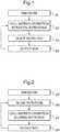
- Fig. 1shows an example of an embodiment of a medical imaging method varying the collimation of the emitted radiation beam.
- the medical imaging method varying the collimation of the emitted radiation beamcomprises a step S1 of emission, a step S2 of collimation variation between rotations, a step S3 of quick rotation, a step S4 of detection.
- the C-armstops rotating at a moment, and during this moment, the collimation of the emitted radiation beam is changed from a former collimation position to a new collimation position.
- the C-armthen rotates again.
- step S3 of quick rotationduring quick rotation of the C-arm, for example during one rotation turn, the collimation of the emitted radiation beam stays unchanged, and therefore the whole rotation turn is performed with the new but constant collimation position.
- Each collimation positionis used successively on a different rotation turn.
- the emitted radiation beam with the new constant collimation positionreaches the radiation detector of the C-arm where it is detected and then processed. Thanks to the collimation of the emitted radiation beam, there is a limited scattered radiation among the detected radiation on the sensitive surface of the radiation detector.
- Dynamic collimationtakes advantage of multiple rotations to capture several tomographic acquisitions, which may be for example rotational or helical, with distinct fields of view composing a tiling of the sensitive surface of the radiation detector. Therefore, with this tiling, at each moment, a part of the sensitive surface of the radiation detector is illuminated by an image of a portion of the volume of interest while another part of the sensitive surface of the radiation detector is shuttered and then can only receive scattered radiation.
- figure 1captures one tile per rotation turn.
- Each acquisitionthus contains, on the one side an illuminated area of the sensitive surface of the radiation detector with reduced scattered radiation, and on the other side a complementary area of the sensitive surface of the radiation detector where scattered radiation is estimated for further subtraction, leading that way to a further reduction of scattered radiation.
- a specific set of the number of rotations and of the sizes and of the shapes of the tilescan be adapted.
- Fig. 2shows an example of another medical imaging method varying the collimation of the emitted radiation beam.
- the medical imaging method varying the collimation of the emitted radiation beamcomprises a step S5 of emission, a step S6 of slow rotation, a step S7 of collimation variation during rotation, a step S8 of detection.
- a radiation beamis emitted by a radiation source which is supported by a C-arm of a medical imaging system. Not all the emitted radiation beam will image the volume of interest, which can be a part of a patient, because part of this emitted radiation beam will be shuttered by a dynamic or variable collimation.
- the C-armis rotating.
- step S6 of slow rotationduring slow rotation of the C-arm, for example during one rotation turn, the collimation of the emitted radiation beam will be often or even continuously changed, and therefore the whole rotation turn is performed with several collimation positions with permanent switching between these collimation positions.
- step S7 of collimation variation during rotationduring each angular portion of the slow, maybe even incremental, rotation of the C-arm corresponding to step S6, switching between both or even between several collimation positions (if more than two of them) is performed. Therefore, during a rotation turn, the complete set of collimation positions has been used several times, maybe many times, for example more than ten times. All collimation positions are used successively and several times on the same rotation turn.
- the emitted radiation beam with the new constant collimation positionarrives on the radiation detector of the C-arm where it is detected and then processed. Thanks to the collimation of the emitted radiation beam, there is a limited scattered radiation among the detected radiation on the sensitive surface of the radiation detector.
- a first type of tilingwill be described in relation to figures 3A to 3D .
- a second type of tilingwill be described in relation to figures 4A to 4E .
- a third type of tilingwill be described in relation to figures 5A to 5C .
- a fourth type of tilingwill be described in relation to figures 6A to 6D .
- Fig. 3A to 3Dshow an example of a first type of tiling and of the associated scanning of the sensitive surface of the radiation detector used to perform a medical imaging method varying the collimation of the emitted radiation beam.
- the associated scanningis preferably an associated linear scanning.
- On each of the figures 3A to 3Dthere is a different collimation position of the blades, and there is a different position of the illuminated strip 1 on the sensitive surface 3 of the radiation detector.
- the sensitive surface 3 of the radiation detectorcan be a square having a side L.
- the sensitive surface 3 of the radiation detectoris a rectangle.
- the illuminated strip 1corresponds to an image of a part of the volume of interest.
- the illuminated strip 1has a length L which is equal to the side L of the sensitive surface 3 of the radiation detector.
- the illuminated strip 1has a width x which is smaller than the side L of the sensitive surface 3 of the radiation detector.
- the portions 2are shuttered portions of the emitted radiation beam. So, the signal received on the corresponding part of the sensitive surface 3 of the radiation detector corresponds to scattered radiation that does not contribute to image formation. This scattered radiation is preferably either discarded or used as an estimate of the scatter radiation within the illuminated strip that is preferably subtracted from the measured radiation in the illuminated strip during subsequent processing.
- the illuminated strip 1is scanning the sensitive surface 3 of the radiation detector from top to bottom, the illuminated strip 1 being translated from top to bottom of the sensitive surface 3 of the radiation detector. At least L/x different discrete positions of the blades are needed for a full scan of the sensitive surface 3 of the radiation detector. Discrete scanning allows for a non-overlapping tiling. Scanning can also be continuous.
- the dynamic collimationdefines a narrow strip in the direction of the axis of rotation of the C-arm, and a long strip orthogonally to this axis of rotation of the C-arm.
- the illuminated strip 1is moved from the top to the bottom of the sensitive surface 3 of the radiation detector, or alternatively the bottom to the top of the sensitive surface 3 of the radiation detector.
- Different examples of tiling with a square flat-panel sensitive surface 3 of the radiation detector using an illuminated strip 1 of relative length 100% of the side of the sensitive surface 3 of the radiation detector in the direction orthogonal to the axis of rotation of the C-arm, and of relative width 100x/L% of the side of the sensitive surface 3 of the radiation detector in the direction of the axis of rotation of the C-arm,can be used.
- Fig. 4A to 4Eshow an example of a second type of tiling and of the associated scanning of the sensitive surface of the radiation detector used to perform a medical imaging method varying the collimation of the emitted radiation beam.
- the sensitive surface 3 of the radiation detectorcan be of rectangular shape with a length L and a width w.
- the illuminated strip 1corresponds to an image of a part of the volume of interest.
- the illuminated strip 1has a width w which is equal to the width w of the sensitive surface 3 of the radiation detector.
- the illuminated strip 1has a length 1 which is smaller than the length L of the sensitive surface 3 of the radiation detector.
- the portions 2are shuttered portions of the emitted radiation beam. So, the signal received on the corresponding part of the sensitive surface 3 of the radiation detector corresponds to scattered radiation that does not contribute to image formation. This scattered radiation is preferably either discarded or used as an estimate of the scatter radiation within the illuminated strip that is preferably subtracted from the measured radiation in the illuminated strip during subsequent processing.
- the illuminated strip 1is scanning the sensitive surface 3 of the radiation detector from left to right, the illuminated strip 1 being translated from left to right of the sensitive surface 3 of the radiation detector. At least L/1 different discrete positions of the blades are needed for a full scan of the sensitive surface 3 of the radiation detector. Discrete scanning allows for a non-overlapping tiling. Scanning can also be continuous.
- Computed tomography scanner gantrycan rotate their narrow and long illuminated strip 1 extremely fast, thus allowing for multiple rotations of the gantry.
- Each rotationcan sample only a sub-fan of the strip.
- Fast rotationcan be substituted with fast dynamic collimation so that each sub-fan is collected successively over a narrow angular sector.
- each tilehas a scatter component that is reduced in magnitude and estimated in the shadow zone for further removal.
- Fig. 5A to 5Cshow an example of a third type of tiling and of the associated scanning of the sensitive surface of the radiation detector used to perform a medical imaging method varying the collimation of the emitted radiation beam.
- Those figuresare quite similar to figures 3A to 3D except that there are two illuminated strips instead of one.
- On each of the figures 5A to 5Cthere is a different collimation position of the blades, and there are different positions of several illuminated strips 1 on the sensitive surface 3 of the radiation detector. Here there are two different illuminated strips 1, but there could be more of them.
- the sensitive surface 3 of the radiation detectoris preferably a square.
- the illuminated strips 1correspond to images of parts of the volume of interest.
- the illuminated strips 1each have a length which is equal to the side of the square of the sensitive surface 3 of the radiation detector.
- the illuminated strips 1each have a width which is smaller than the side of the sensitive surface 3 of the radiation detector.
- the sum of the respective widths of the illuminated strips 1also is smaller than the side of the sensitive surface 3 of the radiation detector.
- the scatter estimation obtained from the measurements in the shuttered part of the sensitive surface 3 of the radiation detectoris most valid in the vicinity of this shuttered part.
- the best estimation of the scattered radiation contribution within an illuminated areais obtained at the edges of this area, as happens with the previously presented strip sliding tiling explained in more detail in relation to figures 3A to 3D .
- a higher speed of measurementcan be obtained with a collimator made of several leaves, so that several illuminated strips 1 are illuminated at once with scattered radiation measurement readings at their edges.
- the portions 2are shuttered portions of the emitted radiation beam. So, the signal received on the corresponding part of the sensitive surface 3 of the radiation detector corresponds to scattered radiation that does not contribute to image formation. This scattered radiation is preferably either discarded or used as an estimate of the scatter radiation within the illuminated strip that is preferably subtracted from the measured radiation in the illuminated strip during subsequent processing. All along the figures 6A to 6D , it can be seen that the illuminated strip 1 is scanning the sensitive surface 3 of the radiation detector from center to both left and right extremities through widening and narrowing of the illuminated strip 1. Here again, scanning can be discrete or continuous.
- a bow-tie filtermodulates the emitted radiation beam according to the expected thickness of volume of interest to penetrate.
- the magnitudeshould be decreased as it goes from the center of the sensitive surface 3 of the radiation detector to its edges.
- the emitted radiation beamcan be adapted depending on the thickness seen by the given tile. This will both reduce the radiation dose to the patient and the scattered radiation magnitude in a very flexible way.
- Another advantage over the bow-tie filteris that the intensity modulation can be used at constant filtration, so that each tile is seen with the same emitted radiation beam. Filtration introduces a non-uniform hardening of the emitted radiation beam over the field of view that is tedious to correct for.
- Bow-tie filtersare also specifically designed per anatomy. Here, it can be adapted dynamically per projection angle.
- the number, width and radiation exposure of the apertures of the collimatorcan be adapted or changed per image of the rotation of the C-arm, contrary to bow-tie filtering which has a fixed modulation.
- the scattered radiation corresponding to the shuttered portion of the sensitive surface 3 of the radiation detectorcan be subtracted and advantageously used in subsequent processing.
Landscapes
- Health & Medical Sciences (AREA)
- Life Sciences & Earth Sciences (AREA)
- Engineering & Computer Science (AREA)
- Medical Informatics (AREA)
- Physics & Mathematics (AREA)
- High Energy & Nuclear Physics (AREA)
- Radiology & Medical Imaging (AREA)
- Molecular Biology (AREA)
- Optics & Photonics (AREA)
- Pathology (AREA)
- Biophysics (AREA)
- Biomedical Technology (AREA)
- Heart & Thoracic Surgery (AREA)
- Nuclear Medicine, Radiotherapy & Molecular Imaging (AREA)
- Surgery (AREA)
- Animal Behavior & Ethology (AREA)
- General Health & Medical Sciences (AREA)
- Public Health (AREA)
- Veterinary Medicine (AREA)
- Spectroscopy & Molecular Physics (AREA)
- General Engineering & Computer Science (AREA)
- Apparatus For Radiation Diagnosis (AREA)
Description
- The invention relates to medical imaging methods and to associated medical imaging systems.
- According to a first prior art, for example described in patent
US7983391B2 , there is a movable radiation shield reducing radiation exposure. In a volume of interest, only a center part of higher interest is refreshed more often than a surrounding part of lower interest. The radiation detector is not rotating. There is radiation exposure lowering. However, there is no scattered radiation lowering for a given radiation exposure of the volume of interest. - According to a second prior art, for example described in patent
US8213568B2 , there is a dynamic collimator shuttering part of the emitted radiation beam to match the beginning and the end of the volume of interest in order to cancel radiation exposure of not needed parts which are just before the beginning of the volume of interest and just after the end of the volume of interest, when performing helical computed tomography. There is cancellation of radiation exposure of useless parts in the vicinity of the volume of interest. However, there is no scattered radiation lowering for a given radiation exposure of the volume of interest. - Several existing imaging methods use collimation variation of an emitted radiation beam. For example,
US2012/0269318 scans only part of a patient body with the help of diaphragm blades, while a gantry is rotating about the patient. The diaphragms can move at varying speed. US633963 discloses two radiation blocking plates that are shifted in steps synchronized with each other to direct irradiation to a site of a patient adjacent to a previous site.- However, none of the prior art uses the specific type of collimation variation of emitted radiation beam by varying collimation during each rotation turn of the gantry such that all collimation positions are scanned at each rotating position of the gantry, used in the invention in order to reduce scattered radiation and thus scan the entire region fast with minimal dose.
- The object of the present invention is to alleviate at least partly the above mentioned drawbacks.
- More particularly, the invention aims at proposing a specific collimation variation of the emitted radiation beam of the medical imaging system which allows for scattered radiation reduction.
- In none of the methods proposed in the reviewed prior art can be found a varying or a dynamic collimation with a rotating gantry or C-arm, such that any first and second parts of a volume of interest to be imaged such that, when said first part of said volume of interest is imaged, said second part of said volume of interest is shuttered, and when said second part of said volume of interest is imaged, said first part of said volume of interest is shuttered, wherein collimation is varied during each rotation turn of the gantry or C-arm so that all collimation positions are scanned at each rotating position of the gantry or C-arm. It is thanks to those parts of a volume of interest to be imaged such that, when said first part of said volume of interest is imaged, said second part of said volume of interest is shuttered, and when said second part of said volume of interest is imaged, said first part of said volume of interest is shuttered, that the volume of interest can be easily imaged whereas the scattered radiation is reduced, and preferably substantially reduced, compared to the scattered radiation obtained with a medical imaging method using no variation of collimation of the emitted radiation beam or some variation of collimation of the emitted radiation beam but for another purpose different from scattered radiation reduction.
- Using varying, or dynamic, collimation of the emitted radiation, for example X-ray, beam, is using a variable collimation during a tomographic acquisition. Indeed, a first set of tomographic acquisition with a given collimated emitted radiation beam is completed by an additional second set of measurements using a different collimation of this same emitted radiation beam. That way, dynamic collimation of the emitted radiation beam provides an extra degree of freedom when designing the sampling of tomographic data, all the more that it is fully compatible with patient or radiation source translation.
- This object is achieved with a medical imaging method according to
claim 1. Preferably the volume of interest at the patient level corresponds to the sensitive surface of the radiation detector at the detection level, or at least to a part of this sensitive surface. The addition of said first and said second parts of volume of interest correspond to said sensitive surface of the radiation detector, or at least to part of this sensitive surface. - For said parts of said volume of interest, switching from imaged to shuttered or switching from shuttered to imaged, occurs by varying collimation.
- Preferably most of parts of said volume of interest, advantageously all parts of said volume of interest can be shared out among couples of a said first part of said volume of interest and of a said second part of said volume of interest.
- This object is achieved with a medical imaging system according to claim 18. Preferred embodiments comprise one or more of the following features, which can be taken separately or together, either in partial combination or in full combination.
- Preferably, said gantry or C-arm is associated to an examination table which stays immobile during gantry or C-arm rotation. The medical imaging method according to embodiments of the invention also works in situations where it is either difficult or uncomfortable to move the examination table. It also works well in situations where the examination table can only be moved very slowly.
- Preferably, said gantry or C-arm is rotating so as to compute three dimensional imaging. Since, in this type of imaging, gantry or C-arm is rotating most of the time, there may be more constraints to vary collimation, but the scattered radiation reduction benefit is high enough. According to the invention, said collimation is varied during each rotation turn of said gantry or C-arm. Here, preferably, the collimation variation is performed relatively often and quickly so that all collimation positions can be scanned at each rotating position of the rotating gantry or C-arm. That way, the whole volume of interest can be imaged, whereas the scattered radiation has been notably reduced compared to a more classical process without collimation variation. Compared to the next alternative, less rotations of gantry or C-arm are needed. In an alternative which is not part of the invention, said collimation is varied between two rotation turns at a same axial position of said gantry or C-arm. Here, preferably, the collimation variation is performed relatively seldom, and can be performed slowly, so that only a single collimation position is kept during a full rotating turn of the rotating gantry or C-arm. That way too, the whole volume of interest can be imaged, whereas the scattered radiation has been notably reduced compared to a more classical process without collimation variation. Compared to the invention, less frequent collimation variations are needed.
- Preferably, said varying collimation is periodical, said gantry or C-arm rotation is periodical, and said varying collimation frequency is equal to or higher than the rotation frequency of said gantry or C-arm. This high relative varying collimation frequency allows for important scattered radiation reduction, since that way, most of the time a narrow collimation position is used to perform imaging.
- Preferably, in an embodiment, said varying collimation changes said field of view size whereas said varying collimation does not change said field of view central position. Preferably, said varying collimation changes said field of view size such as to perform a modulation of the exposure intensity as in a bow-tie filtering on said emitted radiation beam.
- Preferably, in another embodiment, said varying collimation changes said field of view central position whereas said varying collimation does not change said field of view size. That way, the type of imaging performed is the same than a more classical imaging with no collimation variation, but for a much lower scattered radiation.
- Preferably, said varying collimation moves position of said emitted radiation beam so that it scans at least part of a sensitive surface of a radiation detector of said gantry or C-arm. Preferably, said scanning is a linear scanning, said scanning scanning a single direction, said linear scanning preferably scanning a single line. This scanning of the sensitive surface of the radiation detector allows for taking advantage of part of or all the sensitive surface of a large radiation detector while lowering substantially the scattered radiation.
- Preferably, said varying collimation moves respective positions of at least two of said emitted radiation beams so that they respectively scan complementary portions of at least part of a sensitive surface of a radiation detector of said gantry or C-arm. Using several emitted radiation beams is a way to increase and even multiply dynamic collimation frequency which otherwise could be limited by the collimation switching velocity and or by the image chain rotation speed. Indeed, the velocity would be increased by using several radiation, preferably X-ray, focal spots that would each expose a portion of the radiation detector. A simple implementation would use two focal spots, each exposing one half of the sensitive surface of the radiation detector.
- Preferably, in an embodiment, said rotating gantry or C-arm makes full rotations. Preferably, in another embodiment, said rotating gantry or C-arm rotates alternatively clockwise and counter-clockwise.
- Preferably, said varying collimation shutters a portion of said emitted radiation beam which is more than one third, preferably more than one half, more preferably more than two thirds, of said emitted radiation beam, and said varying collimation shutters said portion of said emitted radiation beam during at least part of imaging, preferably during all of imaging. That way, the relatively important portion of shuttered emitted radiation beam lowers all the more the scattered radiation.
- Preferably, when a radiation detector of said gantry or C-arm receives said emitted radiation beam on a first part of its sensitive surface and is shuttered by said varying collimation on a second part of its sensitive surface, a level of radiation detected on said second part is computed as a level of scattered radiation which is then subtracted from a level of radiation detected on said first part. This has the same effect as a supplementary reduction of scattered radiation since part of scattered radiation is eliminated during subsequent signal processing.
- Preferably, in an embodiment, said variably collimated emitted radiation beam transversal shape, transversal with respect to its propagation direction, forms a single window, preferably of constant size.
- Preferably, in another embodiment, said variably collimated emitted radiation beam transversal shape, transversal with respect to its propagation direction, forms several different windows, preferably each of constant size, preferably immobile relatively to one another. This embodiment allows for better scattered radiation elimination during subsequent signal processing, because the level of unwanted scattered radiation can be estimated more precisely, since there is a succession of small and close adjacent zones of transparency to radiation and shuttering of radiation.
- Preferably, said variably collimated emitted radiation beam transversal shape, transversal with respect to its propagation direction, forms one or more rectangular windows. This allows for simpler and more complete scanning of the sensitive surface of the radiation detector.
- Preferably, said varying collimation is performed by several translating blades.
- Further features and advantages of the invention will appear from the following description of embodiments of the invention, given as nonlimiting examples, with reference to the accompanying drawings listed hereunder.
Fig. 1 shows an example of a medical imaging method varying the collimation of the emitted radiation beam.Fig. 2 shows an example of a medical imaging method varying the collimation of the emitted radiation beam.Fig. 3A to 3D show an example of a first type of tiling and of the associated scanning of the sensitive surface of the radiation detector used to perform a medical imaging method varying the collimation of the emitted radiation beam.Fig. 4A to 4E show an example of a second type of tiling and of the associated scanning of the sensitive surface of the radiation detector used to perform a medical imaging method varying the collimation of the emitted radiation beam.Fig. 5A to 5C show an example of a third type of tiling and of the associated scanning of the sensitive surface of the radiation detector used to perform a medical imaging method varying the collimation of the emitted radiation beam.Fig. 6A to 6D show an example of a fourth type of tiling and of the associated scanning of the sensitive surface of the radiation detector used to perform a medical imaging method varying the collimation of the emitted radiation beam.- In all following part of the text, except if otherwise specified, when radiation is used, X-ray which is a specific radiation could be used instead as well. Both applications, on the one hand to radiation in general and on the other hand to X-ray in particular, are intended to be covered. In a similar way, when C-arm is mentioned, any other type of gantry, for example gantry of a computed tomography scanner, unless otherwise specified, could be used instead of the C-arm.
Fig. 1 shows an example of an embodiment of a medical imaging method varying the collimation of the emitted radiation beam. The medical imaging method varying the collimation of the emitted radiation beam comprises a step S1 of emission, a step S2 of collimation variation between rotations, a step S3 of quick rotation, a step S4 of detection.- In the step S1 of emission, a radiation beam is emitted by a radiation source which is supported by a C-arm of a medical imaging system. Not all the emitted radiation beam will image the volume of interest, which can be a part of a patient, because part of this emitted radiation beam will be shuttered by a dynamic or variable collimation. The C-arm is rotating.
- In the step S2 of collimation variation between rotations, the C-arm stops rotating at a moment, and during this moment, the collimation of the emitted radiation beam is changed from a former collimation position to a new collimation position. The C-arm then rotates again.
- In the step S3 of quick rotation, during quick rotation of the C-arm, for example during one rotation turn, the collimation of the emitted radiation beam stays unchanged, and therefore the whole rotation turn is performed with the new but constant collimation position. Each collimation position is used successively on a different rotation turn.
- In the step S4 of detection, the emitted radiation beam with the new constant collimation position reaches the radiation detector of the C-arm where it is detected and then processed. Thanks to the collimation of the emitted radiation beam, there is a limited scattered radiation among the detected radiation on the sensitive surface of the radiation detector.
- Dynamic collimation takes advantage of multiple rotations to capture several tomographic acquisitions, which may be for example rotational or helical, with distinct fields of view composing a tiling of the sensitive surface of the radiation detector. Therefore, with this tiling, at each moment, a part of the sensitive surface of the radiation detector is illuminated by an image of a portion of the volume of interest while another part of the sensitive surface of the radiation detector is shuttered and then can only receive scattered radiation.
- The simple implementation of
figure 1 captures one tile per rotation turn. Each acquisition thus contains, on the one side an illuminated area of the sensitive surface of the radiation detector with reduced scattered radiation, and on the other side a complementary area of the sensitive surface of the radiation detector where scattered radiation is estimated for further subtraction, leading that way to a further reduction of scattered radiation. For each application, a specific set of the number of rotations and of the sizes and of the shapes of the tiles can be adapted. Fig. 2 shows an example of another medical imaging method varying the collimation of the emitted radiation beam. The medical imaging method varying the collimation of the emitted radiation beam comprises a step S5 of emission, a step S6 of slow rotation, a step S7 of collimation variation during rotation, a step S8 of detection.- In the step S5 of emission, a radiation beam is emitted by a radiation source which is supported by a C-arm of a medical imaging system. Not all the emitted radiation beam will image the volume of interest, which can be a part of a patient, because part of this emitted radiation beam will be shuttered by a dynamic or variable collimation. The C-arm is rotating.
- In the step S6 of slow rotation, during slow rotation of the C-arm, for example during one rotation turn, the collimation of the emitted radiation beam will be often or even continuously changed, and therefore the whole rotation turn is performed with several collimation positions with permanent switching between these collimation positions.
- In the step S7 of collimation variation during rotation, during each angular portion of the slow, maybe even incremental, rotation of the C-arm corresponding to step S6, switching between both or even between several collimation positions (if more than two of them) is performed. Therefore, during a rotation turn, the complete set of collimation positions has been used several times, maybe many times, for example more than ten times. All collimation positions are used successively and several times on the same rotation turn.
- In the step S8 of detection, the emitted radiation beam with the new constant collimation position arrives on the radiation detector of the C-arm where it is detected and then processed. Thanks to the collimation of the emitted radiation beam, there is a limited scattered radiation among the detected radiation on the sensitive surface of the radiation detector.
- In the implementation of
figure 2 , where the dynamic collimation is fast with respect to the rotation speed of the C-arm, the change of beam shape is performed during the rotation, allowing a complete tiling to be acquired over a narrow angular sector during a single rotation, this complete tiling being acquired repeatedly over the different narrow angular sectors during a single rotation. This implies that T tiles are acquired in the same time frame as a full projection image, hence requiring a faster imaging chain, which means faster tube exposure and faster detector read out, than what was needed for the implementation offigure 1 . Indeed, given an image chain performance, it suffices to lower the rotation speed T times to fill the previous requirements. In addition, intermediate compromises can be chosen, which means T tiles acquired in R rotations with T/R tiles per angular sector of the rotation of the C-arm. Therefore, each illuminated tile contains a scatter component that is reduced in magnitude and estimated in the shadow zone to be further subtracted, while the stitching of the tiles give rise to a full projection at each sampled angulation. In an option, the tiling may also be overlapping. - Different tiling types providing advantages for producing higher image quality in tomography will now be described. A first type of tiling will be described in relation to
figures 3A to 3D . A second type of tiling will be described in relation tofigures 4A to 4E . A third type of tiling will be described in relation tofigures 5A to 5C . A fourth type of tiling will be described in relation tofigures 6A to 6D . Fig. 3A to 3D show an example of a first type of tiling and of the associated scanning of the sensitive surface of the radiation detector used to perform a medical imaging method varying the collimation of the emitted radiation beam. The associated scanning is preferably an associated linear scanning. On each of thefigures 3A to 3D , there is a different collimation position of the blades, and there is a different position of the illuminatedstrip 1 on thesensitive surface 3 of the radiation detector. Thesensitive surface 3 of the radiation detector can be a square having a side L. Preferably, thesensitive surface 3 of the radiation detector is a rectangle. The illuminatedstrip 1 corresponds to an image of a part of the volume of interest. The illuminatedstrip 1 has a length L which is equal to the side L of thesensitive surface 3 of the radiation detector. The illuminatedstrip 1 has a width x which is smaller than the side L of thesensitive surface 3 of the radiation detector.- The
portions 2 are shuttered portions of the emitted radiation beam. So, the signal received on the corresponding part of thesensitive surface 3 of the radiation detector corresponds to scattered radiation that does not contribute to image formation. This scattered radiation is preferably either discarded or used as an estimate of the scatter radiation within the illuminated strip that is preferably subtracted from the measured radiation in the illuminated strip during subsequent processing. All along thefigures 3A to 3D , it can be seen that the illuminatedstrip 1 is scanning thesensitive surface 3 of the radiation detector from top to bottom, the illuminatedstrip 1 being translated from top to bottom of thesensitive surface 3 of the radiation detector. At least L/x different discrete positions of the blades are needed for a full scan of thesensitive surface 3 of the radiation detector. Discrete scanning allows for a non-overlapping tiling. Scanning can also be continuous. - The dynamic collimation defines a narrow strip in the direction of the axis of rotation of the C-arm, and a long strip orthogonally to this axis of rotation of the C-arm. The illuminated
strip 1 is moved from the top to the bottom of thesensitive surface 3 of the radiation detector, or alternatively the bottom to the top of thesensitive surface 3 of the radiation detector. Depending on the specific application, there can be a parameterization by the number of turns, the speed of rotation of the C-arm, the width of the illuminatedstrip 1 and the translation speed of the illuminatedstrip 1. - Different examples of tiling with a square flat-panel
sensitive surface 3 of the radiation detector using an illuminatedstrip 1 of relative length 100% of the side of thesensitive surface 3 of the radiation detector in the direction orthogonal to the axis of rotation of the C-arm, and of relative width 100x/L% of the side of thesensitive surface 3 of the radiation detector in the direction of the axis of rotation of the C-arm, can be used. The shadow zone, corresponding to shuttered part of thesensitive surface 3 of the radiation detector, has a relative width y=100(1-x/L)%. A given tile thus covers 100x/L% of the projection to targeted field of view. For example, 100x/L%>50%, a maximum of two turns is needed to fully cover the targeted field of view, and the tiling is overlapping. For example, if 100x/L%=50%, the tiling is optimized for two turns without overlapping. For example, if 100x/L%<50%, the tiling will require more than two turns. Fig. 4A to 4E show an example of a second type of tiling and of the associated scanning of the sensitive surface of the radiation detector used to perform a medical imaging method varying the collimation of the emitted radiation beam. On each of thefigures 4A to 4E , there is a different collimation position of the blades, and there is a different position of the illuminatedstrip 1 on thesensitive surface 3 of the radiation detector. Thesensitive surface 3 of the radiation detector can be of rectangular shape with a length L and a width w. The illuminatedstrip 1 corresponds to an image of a part of the volume of interest. The illuminatedstrip 1 has a width w which is equal to the width w of thesensitive surface 3 of the radiation detector. The illuminatedstrip 1 has alength 1 which is smaller than the length L of thesensitive surface 3 of the radiation detector.- The
portions 2 are shuttered portions of the emitted radiation beam. So, the signal received on the corresponding part of thesensitive surface 3 of the radiation detector corresponds to scattered radiation that does not contribute to image formation. This scattered radiation is preferably either discarded or used as an estimate of the scatter radiation within the illuminated strip that is preferably subtracted from the measured radiation in the illuminated strip during subsequent processing. All along thefigures 4A to 4E , it can be seen that the illuminatedstrip 1 is scanning thesensitive surface 3 of the radiation detector from left to right, the illuminatedstrip 1 being translated from left to right of thesensitive surface 3 of the radiation detector. At least L/1 different discrete positions of the blades are needed for a full scan of thesensitive surface 3 of the radiation detector. Discrete scanning allows for a non-overlapping tiling. Scanning can also be continuous. - Computed tomography scanner gantry can rotate their narrow and long illuminated
strip 1 extremely fast, thus allowing for multiple rotations of the gantry. Each rotation can sample only a sub-fan of the strip. Fast rotation can be substituted with fast dynamic collimation so that each sub-fan is collected successively over a narrow angular sector. Again, each tile has a scatter component that is reduced in magnitude and estimated in the shadow zone for further removal. Fig. 5A to 5C show an example of a third type of tiling and of the associated scanning of the sensitive surface of the radiation detector used to perform a medical imaging method varying the collimation of the emitted radiation beam. Those figures are quite similar tofigures 3A to 3D except that there are two illuminated strips instead of one. On each of thefigures 5A to 5C , there is a different collimation position of the blades, and there are different positions of several illuminatedstrips 1 on thesensitive surface 3 of the radiation detector. Here there are two differentilluminated strips 1, but there could be more of them. Thesensitive surface 3 of the radiation detector is preferably a square. The illuminated strips 1 correspond to images of parts of the volume of interest. The illuminated strips 1 each have a length which is equal to the side of the square of thesensitive surface 3 of the radiation detector. The illuminated strips 1 each have a width which is smaller than the side of thesensitive surface 3 of the radiation detector. The sum of the respective widths of theilluminated strips 1 also is smaller than the side of thesensitive surface 3 of the radiation detector.- The
portions 2 are shuttered portions of the emitted radiation beam. So, the signal received on the corresponding part of thesensitive surface 3 of the radiation detector corresponds to scattered radiation that does not contribute to image formation. This scattered radiation is preferably either discarded or used as an estimate of the scatter radiation within the illuminated strip that is preferably subtracted from the measured radiation in the illuminated strip during subsequent processing. All along thefigures 5A to 5C , it can be seen that theilluminated strips 1 are scanning thesensitive surface 3 of the radiation detector from top to bottom, theilluminated strips 1 being translated from top to bottom of thesensitive surface 3 of the radiation detector. Here again, scanning can be discrete or continuous. - The scatter estimation obtained from the measurements in the shuttered part of the
sensitive surface 3 of the radiation detector is most valid in the vicinity of this shuttered part. The best estimation of the scattered radiation contribution within an illuminated area is obtained at the edges of this area, as happens with the previously presented strip sliding tiling explained in more detail in relation tofigures 3A to 3D . Alternatively, with this implementation presented with respect tofigures 5A to 5C , a higher speed of measurement can be obtained with a collimator made of several leaves, so that severalilluminated strips 1 are illuminated at once with scattered radiation measurement readings at their edges. Fig. 6A to 6D show an example of a fourth type of tiling and of the associated scanning of the sensitive surface of the radiation detector used to perform a medical imaging method varying the collimation of the emitted radiation beam. On each of thefigures 6A to 6D , there is a different collimation position of the blades, and there is a different extent of the illuminatedstrip 1 on thesensitive surface 3 of the radiation detector. The illuminatedstrip 1 stays always centered in the middle of thesensitive surface 3 of the radiation detector, at the same distance from both the left and right extremities of thesensitive surface 3 of the radiation detector. Thesensitive surface 3 of the radiation detector is preferably a square having a side L. The illuminatedstrip 1 corresponds to an image of a part of the volume of interest. The illuminatedstrip 1 has a length L which is equal to the side L of thesensitive surface 3 of the radiation detector. The illuminatedstrip 1 has a variable width x which is smaller than or equal to the side L of thesensitive surface 3 of the radiation detector.- The
portions 2 are shuttered portions of the emitted radiation beam. So, the signal received on the corresponding part of thesensitive surface 3 of the radiation detector corresponds to scattered radiation that does not contribute to image formation. This scattered radiation is preferably either discarded or used as an estimate of the scatter radiation within the illuminated strip that is preferably subtracted from the measured radiation in the illuminated strip during subsequent processing. All along thefigures 6A to 6D , it can be seen that the illuminatedstrip 1 is scanning thesensitive surface 3 of the radiation detector from center to both left and right extremities through widening and narrowing of the illuminatedstrip 1. Here again, scanning can be discrete or continuous. - A bow-tie filter modulates the emitted radiation beam according to the expected thickness of volume of interest to penetrate. In fan-beam geometry, the magnitude should be decreased as it goes from the center of the
sensitive surface 3 of the radiation detector to its edges. By combining overlapping column tiling with radiation intensity modulation, the emitted radiation beam can be adapted depending on the thickness seen by the given tile. This will both reduce the radiation dose to the patient and the scattered radiation magnitude in a very flexible way. Another advantage over the bow-tie filter is that the intensity modulation can be used at constant filtration, so that each tile is seen with the same emitted radiation beam. Filtration introduces a non-uniform hardening of the emitted radiation beam over the field of view that is tedious to correct for. Bow-tie filters are also specifically designed per anatomy. Here, it can be adapted dynamically per projection angle. - In cone-beam geometry, there will be an optimal exposure for each tile. A simple implementation approximates the intensity modulation of a bow tie filter using symmetrical collimators to create overlapping centered strips of increasing width. With T tiles, the central part is exposed T times, while the edges are exposed only once. An optimal exposure scheme can be designed by varying the number of tiles and their width according to the expected shape of the volume of interest to be imaged. For head imaging, a symmetrical collimator will be efficient. For abdominal imaging, flat-panel radiation detectors are comparatively small, so one edge of the radiation detector is likely facing small thickness while the other edge is facing large thickness. A non-symmetrical collimator will be used in that case. The number, width and radiation exposure of the apertures of the collimator can be adapted or changed per image of the rotation of the C-arm, contrary to bow-tie filtering which has a fixed modulation. Here again, the scattered radiation corresponding to the shuttered portion of the
sensitive surface 3 of the radiation detector can be subtracted and advantageously used in subsequent processing. - The invention has been described with reference to preferred embodiments. However, many variations are possible within the scope of the invention.
Claims (18)
- Medical imaging method comprising:- emitting (S1) a radiation beam from a radiation source of a rotating gantry, preferably of a rotating C-arm, on a volume of interest,- varying collimation (S2, S7) of said emitted radiation beam so as to change at least part-time a field of view of said emitted radiation beam so that there are at least a first part and a second part of said volume of interest such that, when said first part of said volume of interest is imaged, said second part of said volume of interest is shuttered, and when said second part of said volume of interest is imaged, said first part of said volume of interest is shutteredcharacterized in thatsaid collimation is varied (S7) during each rotation turn (S6) of said gantry or C-arm so that all collimation positions are scanned at each rotating position of said gantry or C-arm.
- Medical imaging method according to claim 1, wherein said gantry or C-arm is associated to an examination table which stays immobile during gantry or C-arm rotation.
- Medical imaging method, according to claim 1 or 2, wherein said gantry or C-arm is rotating so as to compute three dimensional imaging.
- Medical imaging method according to any of claims 1 to 3, wherein said varying collimation (S2, S7) is periodical, said gantry or C-arm rotation (S3, S6) is periodical, and wherein said varying collimation frequency is equal to or higher than the rotation frequency of said gantry or C-arm.
- Medical imaging method according to any of claims 1 to 4, wherein said varying collimation (S2, S7) changes said field of view size whereas said varying collimation (S2, S7) does not change said field of view central position.
- Medical imaging method according to claim 5, wherein said varying collimation (S2, S7) changes said field of view size such as to perform an intensity modulation on said emitted radiation beam.
- Medical imaging method according to any of claims 1 to 4, wherein said varying collimation (S2, S7) changes said field of view central position whereas said varying collimation (S2, S7) does not change said field of view size.
- Medical imaging method according to any of claims 1 to 4 or 7, wherein said varying collimation (S2, S7) moves position of said emitted radiation beam so that it scans at least part of a sensitive surface (3) of a radiation detector of said gantry or C-arm.
- Medical imaging method according to claim 8, wherein said scanning is a linear scanning, said linear scanning preferably scanning a single line.
- Medical imaging method according to any of claims 8 to 9, wherein said varying collimation (S2, S7) moves respective positions of at least two of said emitted radiation beams so that they respectively scan complementary portions of at least part of a sensitive surface (3) of a radiation detector of said gantry or C-arm.
- Medical imaging method according to any of claim 1 to 10, wherein said rotating gantry or C-arm makes full rotations.
- Medical imaging method according to any of claim 1 to 10, wherein said rotating gantry or C-arm rotates alternatively clockwise and counter-clockwise.
- Medical imaging method according to any of preceding claims, wherein said varying collimation (S2, S7) shutters a portion (2) of said emitted radiation beam which is more than one third, preferably more than one half, more preferably more than two thirds, of said emitted radiation beam, and wherein said varying collimation (S2, S7) shutters said portion (2) of said emitted radiation beam during at least part of imaging, preferably during all of imaging.
- Medical imaging method according to any of claims 1 to 13, wherein said variably collimated emitted radiation beam transversal shape, transversal with respect to its propagation direction, forms a single window (1), preferably of constant size.
- Medical imaging method according to any of claims 1 to 13, wherein said variably collimated emitted radiation beam transversal shape, transversal with respect to its propagation direction, forms several different windows (1), preferably each of constant size, preferably immobile relatively to one another.
- Medical imaging method according to any of preceding claims, wherein said variably collimated emitted radiation beam transversal shape, transversal with respect to its propagation direction, forms one or more rectangular windows (1).
- Medical imaging method according to any of preceding claims, wherein, when a radiation detector of said gantry or C-arm receives said emitted radiation beam on a first part (1) of its sensitive surface (3) and is shuttered by said varying collimation on a second part (2) of its sensitive surface (3), a level of radiation detected on said second part (2) is computed as a level of scattered radiation which is then subtracted from a level of radiation detected on said first part (1).
- A medical imaging system comprising:- a rotatable gantry, which is preferably a rotatable C-arm, comprising a radiation source and a collimating device,- said radiation source being adapted to emit (S1) a radiation beam on a volume of interest when said gantry or C-arm rotates,said collimating device being adapted to vary collimation (S2, S7) of said emitted radiation beam so as to change at least part-time a field of view of said emitted radiation beam so that there are at least a first part and a second part of said volume of interest such that, when said first part of said volume of interest is imaged, said second part of said volume of interest is shuttered, and when said second part of said volume of interest is imaged, said first part of said volume of interest is shuttered, said collimating device being adapted to vary collimation (S7) during each rotation turn (S6) of said gantry or C-arm so that all collimation positions are scanned at each rotating position of said gantry or C-arm.
Priority Applications (3)
| Application Number | Priority Date | Filing Date | Title |
|---|---|---|---|
| EP13305755.4AEP2810600B1 (en) | 2013-06-05 | 2013-06-05 | Medical imaging method varying collimation of emitted radiation beam |
| PCT/US2014/039908WO2014197267A1 (en) | 2013-06-05 | 2014-05-29 | Medical imaging method varying collimation of emitted radiation beam |
| US14/958,678US10602995B2 (en) | 2013-06-05 | 2015-12-03 | Medical imaging method varying collimation of emitted radiation beam |
Applications Claiming Priority (1)
| Application Number | Priority Date | Filing Date | Title |
|---|---|---|---|
| EP13305755.4AEP2810600B1 (en) | 2013-06-05 | 2013-06-05 | Medical imaging method varying collimation of emitted radiation beam |
Publications (2)
| Publication Number | Publication Date |
|---|---|
| EP2810600A1 EP2810600A1 (en) | 2014-12-10 |
| EP2810600B1true EP2810600B1 (en) | 2018-08-08 |
Family
ID=49115454
Family Applications (1)
| Application Number | Title | Priority Date | Filing Date |
|---|---|---|---|
| EP13305755.4ANot-in-forceEP2810600B1 (en) | 2013-06-05 | 2013-06-05 | Medical imaging method varying collimation of emitted radiation beam |
Country Status (3)
| Country | Link |
|---|---|
| US (1) | US10602995B2 (en) |
| EP (1) | EP2810600B1 (en) |
| WO (1) | WO2014197267A1 (en) |
Families Citing this family (6)
| Publication number | Priority date | Publication date | Assignee | Title |
|---|---|---|---|---|
| US10117632B2 (en)* | 2016-02-03 | 2018-11-06 | Globus Medical, Inc. | Portable medical imaging system with beam scanning collimator |
| US10842453B2 (en) | 2016-02-03 | 2020-11-24 | Globus Medical, Inc. | Portable medical imaging system |
| US10448910B2 (en) | 2016-02-03 | 2019-10-22 | Globus Medical, Inc. | Portable medical imaging system |
| US11058378B2 (en) | 2016-02-03 | 2021-07-13 | Globus Medical, Inc. | Portable medical imaging system |
| EP3527138B1 (en)* | 2018-01-30 | 2022-06-29 | Globus Medical, Inc. | Portable medical imaging system with beam scanning |
| WO2020069122A1 (en) | 2018-09-28 | 2020-04-02 | Hologic, Inc. | Mini c-arm with increased range of motion |
Family Cites Families (27)
| Publication number | Priority date | Publication date | Assignee | Title |
|---|---|---|---|---|
| US4086494A (en)* | 1976-12-17 | 1978-04-25 | Malak Stephen P | Radiation collimator for use with high energy radiation beams |
| US4203037A (en)* | 1977-08-01 | 1980-05-13 | University Of Pittsburgh | Collimated radiation apparatus |
| DE19905974A1 (en)* | 1999-02-12 | 2000-09-07 | Siemens Ag | Computer tomography scanning method using multi-line detector |
| JP2000262515A (en)* | 1999-03-19 | 2000-09-26 | Fuji Photo Film Co Ltd | Method and apparatus for taking radiation image |
| US7162005B2 (en)* | 2002-07-19 | 2007-01-09 | Varian Medical Systems Technologies, Inc. | Radiation sources and compact radiation scanning systems |
| US20040120457A1 (en)* | 2002-12-20 | 2004-06-24 | University Of Massachusetts Medical Center | Scatter reducing device for imaging |
| WO2004092768A2 (en)* | 2003-04-11 | 2004-10-28 | Fischer Imaging Corporation | Scatter rejection for composite medical imaging systems |
| US6950492B2 (en)* | 2003-06-25 | 2005-09-27 | Besson Guy M | Dynamic multi-spectral X-ray projection imaging |
| JP3999179B2 (en)* | 2003-09-09 | 2007-10-31 | ジーイー・メディカル・システムズ・グローバル・テクノロジー・カンパニー・エルエルシー | Radiation tomography equipment |
| DE102004004630B4 (en)* | 2004-01-29 | 2009-12-31 | Siemens Ag | X-ray equipment |
| EP1720453B1 (en)* | 2004-03-04 | 2010-04-28 | Lodox Systems (Proprietary) Limited | Scanning x-ray apparatus |
| US7539284B2 (en)* | 2005-02-11 | 2009-05-26 | Besson Guy M | Method and system for dynamic low dose X-ray imaging |
| WO2007120744A2 (en)* | 2006-04-14 | 2007-10-25 | William Beaumont Hospital | Scanning slot cone-beam computed tomography and scanning focus spot cone-beam computed tomography |
| US7336760B2 (en)* | 2006-07-28 | 2008-02-26 | Varian Medical Systems Technologies, Inc. | Methods, systems, and computer-program products to estimate scattered radiation in cone-beam computerized tomographic images and the like |
| DE102006044783A1 (en)* | 2006-09-22 | 2008-04-03 | Siemens Ag | Method for capturing images of a determinable region of an examination object by means of a computed tomography device |
| JP2009006133A (en)* | 2007-05-31 | 2009-01-15 | Toshiba Corp | X-ray CT apparatus and control method thereof |
| DE102007028902B4 (en)* | 2007-06-22 | 2009-04-16 | Siemens Ag | Radiator screen, method for their control and X-ray CT apparatus with such radiator aperture |
| US8213568B2 (en) | 2007-12-21 | 2012-07-03 | Koninklijke Philips Electronics N.V. | Dynamic collimation in cone beam computed tomography to reduce patient exposure |
| US8009794B2 (en)* | 2008-01-30 | 2011-08-30 | Varian Medical Systems, Inc. | Methods, apparatus, and computer-program products for increasing accuracy in cone-beam computed tomography |
| US8017915B2 (en)* | 2008-03-14 | 2011-09-13 | Reflexion Medical, Inc. | Method and apparatus for emission guided radiation therapy |
| EP2279494B1 (en)* | 2008-05-21 | 2016-11-02 | Koninklijke Philips N.V. | Dynamic adjustable source collimation during fly-by scanning |
| US20100119033A1 (en)* | 2008-11-12 | 2010-05-13 | The Methodist Hospital Research Institute | Intensity-modulated, cone-beam computed tomographic imaging system, methods, and apparatus |
| US7983391B2 (en) | 2009-04-27 | 2011-07-19 | Machan Lindsay S | System for reduction of exposure to X-ray radiation |
| KR101599028B1 (en)* | 2009-07-23 | 2016-03-03 | 삼성전자주식회사 | - X-ray Apparatus for generating X-ray image for reducing scatter and method thereof |
| EP2662021B1 (en)* | 2011-01-07 | 2020-02-12 | Toshiba Medical Systems Corporation | X-ray ct scanner |
| DE102011007741B4 (en)* | 2011-04-20 | 2021-09-16 | Siemens Healthcare Gmbh | Method and computed tomography device for dynamic CT examination of a patient and data carriers |
| FR3000211B1 (en)* | 2012-12-20 | 2015-12-11 | Commissariat Energie Atomique | SCANNING LIGHTING DEVICE, IMAGING DEVICE COMPRISING SAME, AND METHOD FOR OPERATING SAME |
- 2013
- 2013-06-05EPEP13305755.4Apatent/EP2810600B1/ennot_activeNot-in-force
- 2014
- 2014-05-29WOPCT/US2014/039908patent/WO2014197267A1/enactiveApplication Filing
- 2015
- 2015-12-03USUS14/958,678patent/US10602995B2/enactiveActive
Non-Patent Citations (1)
| Title |
|---|
| None* |
Also Published As
| Publication number | Publication date |
|---|---|
| WO2014197267A1 (en) | 2014-12-11 |
| US10602995B2 (en) | 2020-03-31 |
| EP2810600A1 (en) | 2014-12-10 |
| US20160228074A1 (en) | 2016-08-11 |
Similar Documents
| Publication | Publication Date | Title |
|---|---|---|
| US10602995B2 (en) | Medical imaging method varying collimation of emitted radiation beam | |
| US9628723B2 (en) | Computed tomography scanner calibration with angle correction for scan angle offset | |
| US7920670B2 (en) | Keyhole computed tomography | |
| JP4537129B2 (en) | System for scanning objects in tomosynthesis applications | |
| JP7146811B2 (en) | Reference detector element combined with anti-scatter collimator | |
| JP2012090944A (en) | Radiographic system and radiographic method | |
| JP3961468B2 (en) | Radiation computed tomography apparatus and radiation detector used therefor | |
| JP6488292B2 (en) | X-ray system such as a tomosynthesis system and method for acquiring an image of an object | |
| CN110074803B (en) | Bone density measurement device and bone density imaging method | |
| KR101284986B1 (en) | Method and apparatus for reconstructing high-resolution tomosynthesis | |
| KR101609932B1 (en) | Curved movable beam stop array and CBCT comprising thereof | |
| US12082954B2 (en) | Collimator structure for an imaging system | |
| JP2008528096A (en) | X-ray tomographic image reconstruction method and apparatus | |
| KR20060120511A (en) | Reconstruction method of X-ray CT image and X-ray CT system | |
| US9044187B2 (en) | Post-patient dynamic filter for computed tomography (CT) | |
| US7835485B2 (en) | Method for scattered radiation correction in x-ray imaging devices | |
| CN100539945C (en) | X-ray apparatus | |
| JP5526775B2 (en) | Radiation imaging device | |
| CN110047114A (en) | System and method for improving the spatial resolution in computed tomography | |
| WO2012169426A1 (en) | Radiography system | |
| US6389097B1 (en) | Multi-plate volumetric CT scanner gap compensation method and apparatus | |
| JP2014155509A (en) | Radiographic system | |
| WO2012056992A1 (en) | Radiograph detection device, radiography device, radiography system | |
| WO2012057045A1 (en) | X-ray imaging device, x-ray imaging system | |
| CN104825186B (en) | Radiator diaphragm and relevant computed tomographic apparatus and its control method |
Legal Events
| Date | Code | Title | Description |
|---|---|---|---|
| PUAI | Public reference made under article 153(3) epc to a published international application that has entered the european phase | Free format text:ORIGINAL CODE: 0009012 | |
| 17P | Request for examination filed | Effective date:20130605 | |
| AK | Designated contracting states | Kind code of ref document:A1 Designated state(s):AL AT BE BG CH CY CZ DE DK EE ES FI FR GB GR HR HU IE IS IT LI LT LU LV MC MK MT NL NO PL PT RO RS SE SI SK SM TR | |
| AX | Request for extension of the european patent | Extension state:BA ME | |
| R17P | Request for examination filed (corrected) | Effective date:20150610 | |
| RBV | Designated contracting states (corrected) | Designated state(s):AL AT BE BG CH CY CZ DE DK EE ES FI FR GB GR HR HU IE IS IT LI LT LU LV MC MK MT NL NO PL PT RO RS SE SI SK SM TR | |
| STAA | Information on the status of an ep patent application or granted ep patent | Free format text:STATUS: EXAMINATION IS IN PROGRESS | |
| 17Q | First examination report despatched | Effective date:20170316 | |
| GRAP | Despatch of communication of intention to grant a patent | Free format text:ORIGINAL CODE: EPIDOSNIGR1 | |
| STAA | Information on the status of an ep patent application or granted ep patent | Free format text:STATUS: GRANT OF PATENT IS INTENDED | |
| INTG | Intention to grant announced | Effective date:20180112 | |
| GRAS | Grant fee paid | Free format text:ORIGINAL CODE: EPIDOSNIGR3 | |
| GRAA | (expected) grant | Free format text:ORIGINAL CODE: 0009210 | |
| STAA | Information on the status of an ep patent application or granted ep patent | Free format text:STATUS: THE PATENT HAS BEEN GRANTED | |
| AK | Designated contracting states | Kind code of ref document:B1 Designated state(s):AL AT BE BG CH CY CZ DE DK EE ES FI FR GB GR HR HU IE IS IT LI LT LU LV MC MK MT NL NO PL PT RO RS SE SI SK SM TR | |
| REG | Reference to a national code | Ref country code:GB Ref legal event code:FG4D | |
| REG | Reference to a national code | Ref country code:CH Ref legal event code:EP Ref country code:AT Ref legal event code:REF Ref document number:1026057 Country of ref document:AT Kind code of ref document:T Effective date:20180815 | |
| REG | Reference to a national code | Ref country code:IE Ref legal event code:FG4D | |
| REG | Reference to a national code | Ref country code:DE Ref legal event code:R096 Ref document number:602013041541 Country of ref document:DE | |
| REG | Reference to a national code | Ref country code:NL Ref legal event code:MP Effective date:20180808 | |
| REG | Reference to a national code | Ref country code:LT Ref legal event code:MG4D | |
| REG | Reference to a national code | Ref country code:AT Ref legal event code:MK05 Ref document number:1026057 Country of ref document:AT Kind code of ref document:T Effective date:20180808 | |
| PG25 | Lapsed in a contracting state [announced via postgrant information from national office to epo] | Ref country code:PL Free format text:LAPSE BECAUSE OF FAILURE TO SUBMIT A TRANSLATION OF THE DESCRIPTION OR TO PAY THE FEE WITHIN THE PRESCRIBED TIME-LIMIT Effective date:20180808 Ref country code:IS Free format text:LAPSE BECAUSE OF FAILURE TO SUBMIT A TRANSLATION OF THE DESCRIPTION OR TO PAY THE FEE WITHIN THE PRESCRIBED TIME-LIMIT Effective date:20181208 Ref country code:AT Free format text:LAPSE BECAUSE OF FAILURE TO SUBMIT A TRANSLATION OF THE DESCRIPTION OR TO PAY THE FEE WITHIN THE PRESCRIBED TIME-LIMIT Effective date:20180808 Ref country code:GR Free format text:LAPSE BECAUSE OF FAILURE TO SUBMIT A TRANSLATION OF THE DESCRIPTION OR TO PAY THE FEE WITHIN THE PRESCRIBED TIME-LIMIT Effective date:20181109 Ref country code:SE Free format text:LAPSE BECAUSE OF FAILURE TO SUBMIT A TRANSLATION OF THE DESCRIPTION OR TO PAY THE FEE WITHIN THE PRESCRIBED TIME-LIMIT Effective date:20180808 Ref country code:NO Free format text:LAPSE BECAUSE OF FAILURE TO SUBMIT A TRANSLATION OF THE DESCRIPTION OR TO PAY THE FEE WITHIN THE PRESCRIBED TIME-LIMIT Effective date:20181108 Ref country code:FI Free format text:LAPSE BECAUSE OF FAILURE TO SUBMIT A TRANSLATION OF THE DESCRIPTION OR TO PAY THE FEE WITHIN THE PRESCRIBED TIME-LIMIT Effective date:20180808 Ref country code:RS Free format text:LAPSE BECAUSE OF FAILURE TO SUBMIT A TRANSLATION OF THE DESCRIPTION OR TO PAY THE FEE WITHIN THE PRESCRIBED TIME-LIMIT Effective date:20180808 Ref country code:BG Free format text:LAPSE BECAUSE OF FAILURE TO SUBMIT A TRANSLATION OF THE DESCRIPTION OR TO PAY THE FEE WITHIN THE PRESCRIBED TIME-LIMIT Effective date:20181108 Ref country code:NL Free format text:LAPSE BECAUSE OF FAILURE TO SUBMIT A TRANSLATION OF THE DESCRIPTION OR TO PAY THE FEE WITHIN THE PRESCRIBED TIME-LIMIT Effective date:20180808 Ref country code:LT Free format text:LAPSE BECAUSE OF FAILURE TO SUBMIT A TRANSLATION OF THE DESCRIPTION OR TO PAY THE FEE WITHIN THE PRESCRIBED TIME-LIMIT Effective date:20180808 | |
| PG25 | Lapsed in a contracting state [announced via postgrant information from national office to epo] | Ref country code:HR Free format text:LAPSE BECAUSE OF FAILURE TO SUBMIT A TRANSLATION OF THE DESCRIPTION OR TO PAY THE FEE WITHIN THE PRESCRIBED TIME-LIMIT Effective date:20180808 Ref country code:AL Free format text:LAPSE BECAUSE OF FAILURE TO SUBMIT A TRANSLATION OF THE DESCRIPTION OR TO PAY THE FEE WITHIN THE PRESCRIBED TIME-LIMIT Effective date:20180808 Ref country code:LV Free format text:LAPSE BECAUSE OF FAILURE TO SUBMIT A TRANSLATION OF THE DESCRIPTION OR TO PAY THE FEE WITHIN THE PRESCRIBED TIME-LIMIT Effective date:20180808 | |
| PG25 | Lapsed in a contracting state [announced via postgrant information from national office to epo] | Ref country code:RO Free format text:LAPSE BECAUSE OF FAILURE TO SUBMIT A TRANSLATION OF THE DESCRIPTION OR TO PAY THE FEE WITHIN THE PRESCRIBED TIME-LIMIT Effective date:20180808 Ref country code:IT Free format text:LAPSE BECAUSE OF FAILURE TO SUBMIT A TRANSLATION OF THE DESCRIPTION OR TO PAY THE FEE WITHIN THE PRESCRIBED TIME-LIMIT Effective date:20180808 Ref country code:CZ Free format text:LAPSE BECAUSE OF FAILURE TO SUBMIT A TRANSLATION OF THE DESCRIPTION OR TO PAY THE FEE WITHIN THE PRESCRIBED TIME-LIMIT Effective date:20180808 Ref country code:ES Free format text:LAPSE BECAUSE OF FAILURE TO SUBMIT A TRANSLATION OF THE DESCRIPTION OR TO PAY THE FEE WITHIN THE PRESCRIBED TIME-LIMIT Effective date:20180808 Ref country code:EE Free format text:LAPSE BECAUSE OF FAILURE TO SUBMIT A TRANSLATION OF THE DESCRIPTION OR TO PAY THE FEE WITHIN THE PRESCRIBED TIME-LIMIT Effective date:20180808 | |
| REG | Reference to a national code | Ref country code:DE Ref legal event code:R097 Ref document number:602013041541 Country of ref document:DE | |
| PG25 | Lapsed in a contracting state [announced via postgrant information from national office to epo] | Ref country code:DK Free format text:LAPSE BECAUSE OF FAILURE TO SUBMIT A TRANSLATION OF THE DESCRIPTION OR TO PAY THE FEE WITHIN THE PRESCRIBED TIME-LIMIT Effective date:20180808 Ref country code:SM Free format text:LAPSE BECAUSE OF FAILURE TO SUBMIT A TRANSLATION OF THE DESCRIPTION OR TO PAY THE FEE WITHIN THE PRESCRIBED TIME-LIMIT Effective date:20180808 Ref country code:SK Free format text:LAPSE BECAUSE OF FAILURE TO SUBMIT A TRANSLATION OF THE DESCRIPTION OR TO PAY THE FEE WITHIN THE PRESCRIBED TIME-LIMIT Effective date:20180808 | |
| PLBE | No opposition filed within time limit | Free format text:ORIGINAL CODE: 0009261 | |
| STAA | Information on the status of an ep patent application or granted ep patent | Free format text:STATUS: NO OPPOSITION FILED WITHIN TIME LIMIT | |
| 26N | No opposition filed | Effective date:20190509 | |
| PG25 | Lapsed in a contracting state [announced via postgrant information from national office to epo] | Ref country code:SI Free format text:LAPSE BECAUSE OF FAILURE TO SUBMIT A TRANSLATION OF THE DESCRIPTION OR TO PAY THE FEE WITHIN THE PRESCRIBED TIME-LIMIT Effective date:20180808 | |
| PG25 | Lapsed in a contracting state [announced via postgrant information from national office to epo] | Ref country code:MC Free format text:LAPSE BECAUSE OF FAILURE TO SUBMIT A TRANSLATION OF THE DESCRIPTION OR TO PAY THE FEE WITHIN THE PRESCRIBED TIME-LIMIT Effective date:20180808 | |
| REG | Reference to a national code | Ref country code:CH Ref legal event code:PL | |
| GBPC | Gb: european patent ceased through non-payment of renewal fee | Effective date:20190605 | |
| REG | Reference to a national code | Ref country code:BE Ref legal event code:MM Effective date:20190630 | |
| PG25 | Lapsed in a contracting state [announced via postgrant information from national office to epo] | Ref country code:TR Free format text:LAPSE BECAUSE OF FAILURE TO SUBMIT A TRANSLATION OF THE DESCRIPTION OR TO PAY THE FEE WITHIN THE PRESCRIBED TIME-LIMIT Effective date:20180808 | |
| PG25 | Lapsed in a contracting state [announced via postgrant information from national office to epo] | Ref country code:IE Free format text:LAPSE BECAUSE OF NON-PAYMENT OF DUE FEES Effective date:20190605 Ref country code:GB Free format text:LAPSE BECAUSE OF NON-PAYMENT OF DUE FEES Effective date:20190605 | |
| PG25 | Lapsed in a contracting state [announced via postgrant information from national office to epo] | Ref country code:BE Free format text:LAPSE BECAUSE OF NON-PAYMENT OF DUE FEES Effective date:20190630 Ref country code:LU Free format text:LAPSE BECAUSE OF NON-PAYMENT OF DUE FEES Effective date:20190605 Ref country code:CH Free format text:LAPSE BECAUSE OF NON-PAYMENT OF DUE FEES Effective date:20190630 Ref country code:LI Free format text:LAPSE BECAUSE OF NON-PAYMENT OF DUE FEES Effective date:20190630 | |
| PG25 | Lapsed in a contracting state [announced via postgrant information from national office to epo] | Ref country code:PT Free format text:LAPSE BECAUSE OF FAILURE TO SUBMIT A TRANSLATION OF THE DESCRIPTION OR TO PAY THE FEE WITHIN THE PRESCRIBED TIME-LIMIT Effective date:20181208 | |
| PG25 | Lapsed in a contracting state [announced via postgrant information from national office to epo] | Ref country code:CY Free format text:LAPSE BECAUSE OF FAILURE TO SUBMIT A TRANSLATION OF THE DESCRIPTION OR TO PAY THE FEE WITHIN THE PRESCRIBED TIME-LIMIT Effective date:20180808 | |
| PG25 | Lapsed in a contracting state [announced via postgrant information from national office to epo] | Ref country code:HU Free format text:LAPSE BECAUSE OF FAILURE TO SUBMIT A TRANSLATION OF THE DESCRIPTION OR TO PAY THE FEE WITHIN THE PRESCRIBED TIME-LIMIT; INVALID AB INITIO Effective date:20130605 Ref country code:MT Free format text:LAPSE BECAUSE OF FAILURE TO SUBMIT A TRANSLATION OF THE DESCRIPTION OR TO PAY THE FEE WITHIN THE PRESCRIBED TIME-LIMIT Effective date:20180808 | |
| PG25 | Lapsed in a contracting state [announced via postgrant information from national office to epo] | Ref country code:MK Free format text:LAPSE BECAUSE OF FAILURE TO SUBMIT A TRANSLATION OF THE DESCRIPTION OR TO PAY THE FEE WITHIN THE PRESCRIBED TIME-LIMIT Effective date:20180808 | |
| PGFP | Annual fee paid to national office [announced via postgrant information from national office to epo] | Ref country code:FR Payment date:20220519 Year of fee payment:10 Ref country code:DE Payment date:20220518 Year of fee payment:10 | |
| REG | Reference to a national code | Ref country code:DE Ref legal event code:R119 Ref document number:602013041541 Country of ref document:DE | |
| PG25 | Lapsed in a contracting state [announced via postgrant information from national office to epo] | Ref country code:DE Free format text:LAPSE BECAUSE OF NON-PAYMENT OF DUE FEES Effective date:20240103 | |
| PG25 | Lapsed in a contracting state [announced via postgrant information from national office to epo] | Ref country code:FR Free format text:LAPSE BECAUSE OF NON-PAYMENT OF DUE FEES Effective date:20230630 |