EP2810019B1 - Measuring system with a measuring device and a scan module - Google Patents
Measuring system with a measuring device and a scan moduleDownload PDFInfo
- Publication number
- EP2810019B1 EP2810019B1EP13701791.9AEP13701791AEP2810019B1EP 2810019 B1EP2810019 B1EP 2810019B1EP 13701791 AEP13701791 AEP 13701791AEP 2810019 B1EP2810019 B1EP 2810019B1
- Authority
- EP
- European Patent Office
- Prior art keywords
- scanning module
- scanning
- laser beam
- distance
- angle
- Prior art date
- Legal status (The legal status is an assumption and is not a legal conclusion. Google has not performed a legal analysis and makes no representation as to the accuracy of the status listed.)
- Active
Links
- 238000005259measurementMethods0.000claimsdescription64
- 238000012545processingMethods0.000claimsdescription41
- 238000000034methodMethods0.000claimsdescription18
- 230000003287optical effectEffects0.000claimsdescription18
- 230000008685targetingEffects0.000claimsdescription12
- 230000008878couplingEffects0.000claimsdescription5
- 238000010168coupling processMethods0.000claimsdescription5
- 238000005859coupling reactionMethods0.000claimsdescription5
- 230000003993interactionEffects0.000claimsdescription5
- 238000004590computer programMethods0.000claimsdescription3
- 238000010276constructionMethods0.000claims4
- 238000001514detection methodMethods0.000description16
- 230000005855radiationEffects0.000description6
- 238000012937correctionMethods0.000description5
- 230000006870functionEffects0.000description5
- 230000008569processEffects0.000description5
- 230000005540biological transmissionEffects0.000description4
- 238000004364calculation methodMethods0.000description4
- 238000003860storageMethods0.000description4
- 238000012876topographyMethods0.000description4
- 229910000831SteelInorganic materials0.000description3
- 239000010959steelSubstances0.000description3
- 238000009825accumulationMethods0.000description2
- 238000013459approachMethods0.000description2
- 238000003491arrayMethods0.000description2
- 238000009795derivationMethods0.000description2
- 238000013461designMethods0.000description2
- 238000009826distributionMethods0.000description2
- 230000002093peripheral effectEffects0.000description2
- 239000012780transparent materialSubstances0.000description2
- 230000006978adaptationEffects0.000description1
- 230000006399behaviorEffects0.000description1
- 230000008859changeEffects0.000description1
- 230000001427coherent effectEffects0.000description1
- 238000004891communicationMethods0.000description1
- 238000007906compressionMethods0.000description1
- 230000006835compressionEffects0.000description1
- 238000013144data compressionMethods0.000description1
- 238000013500data storageMethods0.000description1
- 230000001419dependent effectEffects0.000description1
- 238000006073displacement reactionMethods0.000description1
- 239000000835fiberSubstances0.000description1
- 238000001914filtrationMethods0.000description1
- 230000001939inductive effectEffects0.000description1
- 238000005304joiningMethods0.000description1
- 238000004519manufacturing processMethods0.000description1
- 239000000463materialSubstances0.000description1
- 239000000203mixtureSubstances0.000description1
- 238000012986modificationMethods0.000description1
- 230000004048modificationEffects0.000description1
- 238000012634optical imagingMethods0.000description1
- 230000001012protectorEffects0.000description1
- 238000005070samplingMethods0.000description1
- 238000011895specific detectionMethods0.000description1
- 239000013589supplementSubstances0.000description1
- 230000009897systematic effectEffects0.000description1
- 238000012546transferMethods0.000description1
- 238000013519translationMethods0.000description1
- 230000000007visual effectEffects0.000description1
Images


Classifications
- G—PHYSICS
- G01—MEASURING; TESTING
- G01C—MEASURING DISTANCES, LEVELS OR BEARINGS; SURVEYING; NAVIGATION; GYROSCOPIC INSTRUMENTS; PHOTOGRAMMETRY OR VIDEOGRAMMETRY
- G01C15/00—Surveying instruments or accessories not provided for in groups G01C1/00 - G01C13/00
- G01C15/002—Active optical surveying means
- G—PHYSICS
- G01—MEASURING; TESTING
- G01S—RADIO DIRECTION-FINDING; RADIO NAVIGATION; DETERMINING DISTANCE OR VELOCITY BY USE OF RADIO WAVES; LOCATING OR PRESENCE-DETECTING BY USE OF THE REFLECTION OR RERADIATION OF RADIO WAVES; ANALOGOUS ARRANGEMENTS USING OTHER WAVES
- G01S17/00—Systems using the reflection or reradiation of electromagnetic waves other than radio waves, e.g. lidar systems
- G01S17/88—Lidar systems specially adapted for specific applications
- G01S17/89—Lidar systems specially adapted for specific applications for mapping or imaging
- G—PHYSICS
- G01—MEASURING; TESTING
- G01C—MEASURING DISTANCES, LEVELS OR BEARINGS; SURVEYING; NAVIGATION; GYROSCOPIC INSTRUMENTS; PHOTOGRAMMETRY OR VIDEOGRAMMETRY
- G01C1/00—Measuring angles
- G01C1/02—Theodolites
- G—PHYSICS
- G01—MEASURING; TESTING
- G01C—MEASURING DISTANCES, LEVELS OR BEARINGS; SURVEYING; NAVIGATION; GYROSCOPIC INSTRUMENTS; PHOTOGRAMMETRY OR VIDEOGRAMMETRY
- G01C15/00—Surveying instruments or accessories not provided for in groups G01C1/00 - G01C13/00
- G01C15/002—Active optical surveying means
- G01C15/004—Reference lines, planes or sectors
- G01C15/006—Detectors therefor
- G—PHYSICS
- G01—MEASURING; TESTING
- G01S—RADIO DIRECTION-FINDING; RADIO NAVIGATION; DETERMINING DISTANCE OR VELOCITY BY USE OF RADIO WAVES; LOCATING OR PRESENCE-DETECTING BY USE OF THE REFLECTION OR RERADIATION OF RADIO WAVES; ANALOGOUS ARRANGEMENTS USING OTHER WAVES
- G01S7/00—Details of systems according to groups G01S13/00, G01S15/00, G01S17/00
- G01S7/48—Details of systems according to groups G01S13/00, G01S15/00, G01S17/00 of systems according to group G01S17/00
- G01S7/481—Constructional features, e.g. arrangements of optical elements
- G01S7/4817—Constructional features, e.g. arrangements of optical elements relating to scanning
Definitions
- the inventionrelates to a surveying system with a surveying device and a scanning module according to the preamble of claim 1, a scanning module according to the invention according to claim 8, a surveying device according to claim 13 and a scanning method according to claim 14 and a computer program product according to claim 15.
- a structuresuch as a surface. of a building, successive scanning and recording.
- Such a topographyrepresents a coherent sequence of points describing the surface of the object or a corresponding model or description of the surface.
- a common approachis the scanning by means of a laser scanner, which respectively detects the spatial position of a surface point by moving through the Laser the distance to the targeted surface point measured and this measurement are linked to the angle information of the laser emission. From this distance and angle information, the spatial position of the detected point can be determined and the surface can be measured continuously.
- an image acquisitionis also performed by a camera which, in addition to the overall visual view, also contains further information, e.g. regarding the surface texture.
- WO 97/40342describes a method which records a topography by stationary scanner systems.
- a fixed point of setupis used, which serves as the basis of a scan engine-induced scan.
- the three-dimensional location information of the respective surface pointcan be derived by the distance to the measured point, the angular position at the time of the measurement and the known location of the scanning device.
- the scanner systemsare specially designed for the task of topography detection and scan a surface by moving the scanner system or by changing the beam path.
- scanning functionscan be integrated into various other devices as additional functions.
- a geodetic measuring devicewhich emits a laser beam for distance measurement from its position within the detected area.
- Such measuring devicescan also be modified for the scanning detection of surfaces or operated without modification.
- An example of thisis motorized theodolites or total stations.
- Other methodsuse mobile systems that scan a structure to be detected by a movement of the scanner system or support the sampling or supplement.
- Such systemsare particularly suitable for detecting linear or linearly drivable structures, such as track systems, roads, tunnel systems or airfields.
- Such state-of-the-art detection processesprovide images or topographic data that essentially represent information about the spatial distribution or relationship of surface points. If necessary, allow in addition taken pictures the derivation of further information. Thus, the structure and the course of the surface are comparatively easy to reconstruct.
- a disadvantageis the lack of qualitative information about the nature and condition of the surface, in particular with regard to the internal structure or composition. For example, images taken parallel to the scan usually allow the identification of different brightness values.
- EP 1 759 172a scanner system and method for detecting surfaces in spectrally resolved form that provides derivation of surface properties from the information obtained thereby.
- Such prior art laser scannersenable a user to acquire large surfaces and objects with a relatively small amount of time - depending on a desired point-to-point resolution - completely and optionally with additional object information, but the accuracy of the point coordinates derived thereby is insufficient the high geodetic accuracy standards, such as those for modern surveying equipment, especially for total stations or thedolites, are established.
- Modern total stationsusually have a compact and integrated design, with mostly coaxial distance measuring elements and computing, control and storage units are available in a device.
- a motorization of the sighting or sighting device and - in the case of the use of retroreflectors (such as a wrap-around prism) as target objects - means for automatic target search and trackingcan also be integrated.
- the total stationcan have an electronic display control unit-generally a microprocessor processor with electronic data storage means-with display and input means, eg a keyboard.
- the display control unitis supplied with the electrosensory measurement data, so that the position of the target point by the display control unit can be determined, visually displayed and stored.
- Total stations known from the prior artcan furthermore have a radio data interface for setting up a radio link to external peripheral components, such as a handheld data acquisition device, which can be configured in particular as a data logger or field computer.
- geodetic surveying devices of the generic typecomprise a sighting telescope, such as an optical telescope, as a sighting device.
- the scopeis generally rotatable about a vertical standing axis and about a horizontal tilting axis relative to a base of the measuring device so that the telescope can be aligned by pivoting and tilting on the point to be measured.
- Modern devicescan additively to the optical view channel integrated into the scope and, for example, coaxial or parallel aligned camera for sighting with angular second accuracy.
- the thereby detectable images or image sequences, in particular a live imagecan be displayed on the display of the display control unit and / or on a display of the peripheral device used for remote control - such as the data logger.
- the optics of the sighting devicecan be a manual focus - for example, a screw for Change the position of a focusing optics - have or have an autofocus, wherein the changing of the focus position, for example by servomotors.
- Automatic focusing devices for riflescopes of geodetic devicesare eg from DE 197 107 22 , of the DE 199 267 06 or the DE 199 495 80 known.
- target objectseg the most commonly used for geodetic purposes plumb bobs with target such as an all-round prism
- ATRAutomatic Target Recognition
- a further separate ATR light sourcefor example a multimode fiber output which emits optical radiation having a wavelength in the region of 850 nm - and a special, sensitive for this wavelength ATR detector (eg CCD or CMOS area sensor) are also commonly in the telescope integrated.
- a surveying device with auto-aiming function for a retroreflective target and with automatic tracking functionalityare also commonly in the telescope integrated.
- the coordinates of appropriate target pointscan be determined with a very high geodetic precision.
- the disadvantage hereis that a large-scale object measurement For example, with a total station a disproportionately high amount of time - compared to a measuring operation of a laser scanner on the object - means.
- a further object of the inventionis to expand a prior art surveying device in such a way that a scanning functionality is additionally provided for the surveying device.
- a surveying systemcomprises a surveying device, in particular total station, theodolite or laser tracker, with a base, a structure arranged on the base, pivotable about a pivot axis, and a target unit, in particular a target telescope, wherein the target unit has at least one emission unit defining an optical target axis to issue a first Laser beam, and a first distance measuring functionality for measuring a distance to an object.
- the surveying devicehas a first angle measuring functionality for the high-precision detection of at least one pivoting angle defined by a relative pivoting position of the body to the base.
- the surveying systemalso has a control and processing unit for data processing and control of the surveying system.
- the surveying systemhas a scanning module with fastening means for fastening the scanning module to a mounting with the fastening means, with a rotatable about a rotation axis rotatable Strahlumlenkelement for deflecting a Scanlaserstrahls, the rotation axis is in a recorded state at a defined angle relative to the pivot axis, in particular orthogonal, and with a second angle measuring functionality for determining a rotation angle from an angular position of the Strahlumlenkelements.
- the surveying devicehas a receptacle designed in such a way that the scanning module can be fastened in a modular manner by a cooperation of the receptacle with the fastening means on the surveying device in a defined positioning.
- the control and processing unitis also designed such that the respective rotation angle, the respective pivoting angle and the respective distance are linked for a point on the object, so that by the linkage in each case a point position is defined, and a number of points Positioned point cloud can be generated.
- a laser plane or a laser surfacein particular of a higher order, can be defined by the rotating movement of the deflecting element, for example a mirror, and the deflection of the scanning laser beam impinging thereon.
- the scanning modulein which the mirror rotates, is pivoted about a second axis by means of the surveying device serving as a swiveling device, the laser plane can now be displaced continuously and thus an environment can be scanned continuously with the emitted laser beam.
- an emission direction of the laser beam relative to the scan module and to the second relative to the base of the surveying apparatusis determined at each point on which the laser beam impinges and is detected by a detector for the purpose of distance measurement.
- the distance measurementcan be carried out, for example, according to the phase measurement principle or by means of a transit time determination.
- value arrayscan be generated, each array representing a coordinate of the measured point. For example, angles and distances detected simultaneously or within a specific time interval or at defined time intervals can be linked.
- a point cloud embodying the measured environmentmay be further generated by assembling a plurality of such value arrays.
- the scanning moduleis designed such that it can be removed from the pivoting unit or placed thereon in a modular manner by means of fastening means provided specifically for this purpose.
- a tripod with a a tripod fixed base and a mounted on the base, relative thereto pivotable structureserve as a pivoting device for the inventive surveying system.
- recordingscan be arranged on such a device, each of which is suitable for receiving the scan module, so that a defined connection arises between the components, which can be released again in a simple manner.
- a suitable receptacle and corresponding fastening meanscan in principle cooperate and be designed according to a plug-socket principle.
- the scanning modulecan have a beam passage unit and the targeting unit can be aligned in such a way that the first laser beam can be coupled into the scanning module by means of the beam passage unit and can be rotationally deflected by the beam deflecting element about the axis of rotation as a scanning laser beam, in particular a scan laser beam reflected at the object can be decoupled from the scan module by means of the beam passage unit.
- the scanning module of the surveying systemcan also have a detection unit designed in such a way that an incident position of the first laser beam which can be deflected onto the detection unit in the coupling-in state can be detected on the detection unit, wherein a positioning parameter indicative of relative positioning of the scanning module relative to the surveying device can be generated as a function of the impact position is, in particular wherein by means of the positioning parameter, the point positions are correctable.
- the emissive by means of the target unit first laser beamcan be aligned by a defined alignment of the targeting unit such that the beam is directed to the beam passage unit and is transmitted or coupled by them into the scan module.
- the beam passage unitcan be used for this purpose e.g. be formed with a specific optically transparent material, so that in each case that radiation of the emission unit of the surveying device is transmitted with a specific wavelength through the material.
- the laser radiationis then guided, for example by means of mirrors, prisms and / or lenses, to the beam deflecting element where it is deflected at a certain angle and emitted from the scanning module.
- the objectcan be scanned in this way.
- the reflected beamcan thus be decoupled from the scan module corresponding to an emission beam path and coupled into the surveying device and thus again received at the surveying device and the distance to the object thus measured by means of the distance measuring functionality of the target unit.
- parameterscan be determined with which a determination of the Positioning of the scan module on the surveying device can be completed. For example, from a storage of the incident laser beam from an image center of the detection unit - depending on the direction and distance from the center - information regarding the position and orientation of the scanning module relative to the surveying device can be obtained.
- the parameters ascertained or generated measuring signalscan be made available to the control and processing unit for determining eg correction parameters. These in turn can also be used for the compensation of measured values or can be displayed to a user graphically, for example on a display, so that the latter can perform a position correction of the two components (surveying device and scanning module) relative to one another.
- the scanning modulecan have a beam source for emitting a second laser beam as a scanning laser beam and the scanning laser beam can be rotationally deflected about the rotational axis by means of the beam deflecting element, in particular wherein the scanning module has a second distance measuring functionality for distance measurement, in particular by means of the scanning laser beam.
- the laser beamcan be emitted for scanning an object independently of the surveying device and coupling of the steel into the scan module need not be undertaken to provide the scan functionality.
- the scan modulemay also have further ranging capability and receive a reflected scan beam on the scan module Distance to the object be measurable. In this configuration, both the rotation angle and the distance can be determined by the scan module. The swivel angle can be determined by means of the surveying device.
- the swivel anglecan be transmitted to a control and processing unit assigned to the scan module and the linking, further processing and / or provision of swivel angle, rotation angle and distance can take place there.
- rotation angle and distancecan be transmitted to a control and processing unit associated with the surveying device and linked and provided by the surveying device.
- the data for linking, processing and / or providing a mobile or stationary unite.g. Work computer, laptop or remote control for the system to be provided with control and processing unit.
- the data transmissioncan also be wired, by radio, WLAN, infrared or via Bluetooth.
- the surveying systemcan have at least one distance measuring sensor for measuring a distance between the scanning module and the surveying device in the recorded state for generating a further positioning parameter indicating the relative positioning of the scanning module relative to the surveying device.
- a relative position of the scanning module on the surveying devicecan be precisely determined, in particular if three such sensors are provided for this position determination-not lying on a straight line. So can distances measured between the components and from a reference to the distances, for example, a relative inclination of the components are determined to each other. Accordingly, if the position and orientation of the surveying device is known, an unambiguous determination of the orientation and, if the positioning of the scanning module on the surveying device is defined, the position of the scanning module can be determined by means of the sensors. From these measurements, the system can be provided with information on the position and orientation, for example in a defined parameter form, and further processed for purposes of compensation or adaptation of coordinates to be determined, in particular by the control and processing unit.
- the surveying systemcan have an at least two-component centering device for defined positioning of the scanning module on the surveying device, wherein a first component is assigned to the scanning module and a second component to the surveying device, in particular a positioning accuracy by means of sensors for determining a relative positioning of the first to the second component is measurable.
- such a centering devicecan be integrated into the surveying system or be arranged thereon.
- a high mounting precisioncan be achieved when mounting the scanning module on the surveying equipment.
- sensorsmay be provided with which distances of the centering components to one another and thus a centering accuracy can be determined.
- Such a centering devicecan for example consist of a pin as a first component and a receptacle as a second component, which is designed for precise recording of the pin, in particular while maintaining a defined tolerance.
- sensors for measuring the distance to the pincan be arranged on the sides of the pin receptacle facing the pin in a centering state.
- a well-known, detachable precision connection with backlash-free positive centeringis known as an interface to the tribrach on the theodolite base.
- the connection of the scanning module to the surveying devicecan be carried out in a comparable manner.
- the surveying systemcan have a camera for capturing an image.
- a camerafor capturing an image.
- an image of the environment or of the object to be measuredcan be recorded, wherein information captured in the image can be used to characterize the object or its surface.
- additional object propertiesin particular selectively resolved, can be derived and further processed.
- the cameracan be arranged and configured in the surveying system in such a way that the image is detected by means of the beam deflection element, ie incident light can be directed onto the camera with the aid of the beam deflection element.
- the beam deflection elementcan be embodied by a mirror, in particular by a polygon mirror.
- the deflection of the laser beamcan thus take place in dependence on the configuration of the mirror and its relative inclination to a direction of incidence of the laser beam at a defined angle.
- the deflection of the laser beamcan thereby take place several times within a complete revolution of the polygon mirror.
- an inclination or tilting of the scanning module relative to the surveying devicecan also be determined by scanning a distinctive structure (with the scanning module and the surveying device), the relative inclination depending on a comparison of a scanning point cloud generated by the scanning module and representing the distinctive structure determined by the surveying device, representing the distinctive structure survey point cloud is determined.
- the inventionfurther relates to a scanning module according to the invention for a surveying system according to the invention with a beam deflection element rotatable about a rotation axis for deflecting a scanning laser beam and an angle measurement functionality for determining a rotation angle from an angular position of the beam deflection element.
- the scanning modulehas fastening means for fastening the scanning module to a receptacle corresponding to the fastening means, wherein the scanning module can be fastened to the surveying device in a defined positioning in a modular manner by cooperation of the fastening means with the receptacle arranged on a surveying device, in particular total station, theodolite or laser tracker is.
- the scanning module for transferring the rotation angle to a control and processing unit according to the inventive surveying systemis formed.
- such a scanning module or a scanner scannercan generate a laser plane, wherein both the emitted laser beam and a beam reflected at an object are guided by the beam deflection element or from the beam source to the object and in accordance with a specific measurement direction can be directed from the object to the detector.
- the respective emission and reception direction of the beamcan be further determined. If distances to points are now measured by means of the laser beam and these distances are linked to the angles existing at the time of measurement, a coordinate of the respective target point can be determined from each distance-angle combination and the point cloud can be generated by means of an accumulation or accumulation of these points.
- the scanning modulecan be placed and fastened with the fastening means on a device, in particular by means of a receiving device provided for this purpose.
- a receiving deviceprovided for this purpose.
- the scanning moduleabout a second axis which is perpendicular to the axis of rotation of the Strahlumlenkelements be pivoted or rotated, whereby the laser plane is pivoted accordingly and thus generation of a point cloud of a Vietnameseschwenkten measurement environment or a pivoted object is feasible.
- the data generated by the scanning modulein particular rotation angles, can be used by the control and processing unit, eg a total station, for Linking rotation angles with swivel angles and distances can be provided.
- the scanning modulecan have a beam passage unit for coupling and / or decoupling the scan laser beam so that at least the coupled scanning laser beam can be deflected in a rotating manner about the rotation axis by means of the beam deflection element.
- a laser beam from a beam source physically separate from the scan modulecan be irradiated into the scan module and guided in such a way that the beam can be used as a scan laser beam and deflected by means of the beam deflection element.
- the distance measurement to the objectcan also be done on the basis of the coupled laser beam.
- the beam reflected by the objectcan again be received by the scanning module, deflected by the beam deflection element and coupled out by the beam passage unit, which is formed, for example, with optically transparent material, so that the coupled-out beam is detected by a detector for the purpose of distance measurement.
- the scanning modulecan have a detection unit for detecting the scanning laser beam, wherein the detection unit has a distance measuring functionality for measuring the distance to an object and / or a position-sensitive sensor for determining an incident position of the scanning laser beam on a sensor.
- the scanning modulecan have a beam source for emitting the scanning laser beam and the scanning laser beam can be rotationally deflected about the rotational axis by means of the beam deflecting element.
- both the rotation angle and the distances for points on the objectcan be determined with the scan module.
- the beam sourcecan emit a laser beam in such a way that it impinges on the beam deflection element and is deflected therefrom onto the object.
- further beam guiding meanscan be provided, which guide the emitted beam such that it impinges on the beam deflecting element and optionally the reflected laser beam is guided towards the detector.
- the laser beam sourcecan emit, for example, a largely collimated laser beam or a defined expanded, divergent beam.
- the scan module according to the inventioncan furthermore have a data interface designed in such a way that information, in particular angle information and / or distance information, can be transmitted from the scan module to a device, in particular a surveying device, connected to the scanning module by means of the fastening means, in particular wherein the information can be transmitted between the scan module and the device ,
- a data interfaceBy means of such a data interface, the rotation angle determined by the scan module can be transmitted, for example, to the processing unit of a surveying device, where it can be linked with swivel angle and distance information for respective points. With such a link, coordinates for each point can be generated.
- the data transfer in the opposite direction, from the surveying device to the scan module, done and the processing of the informationis carried out with a corresponding control and processing unit by the scanning module.
- the scanning modulecan have a control and processing unit for data processing and control of the orientation of the beam deflecting element, wherein the control and processing unit is designed such that upon receipt of a pivot angle information generated by the surveying device and in particular a distance information indicating the distance to an object Rotation angle, the respective pivoting angle and the respective distance for a point on the object are linked so that the linkage in each case a point position is defined on the object.
- a point cloud having a number of point positionscan be generated.
- the inventive scanning modulecan have an inclination sensor and / or a camera for capturing an image.
- a positioning of the scanning modulein particular independent of a positioning and alignment of a surveying device, can be determined and the scanning module can be brought into a defined position.
- a leveling of the modulecan be adjusted or checked by means of a level, or a compensation or correction of detected point coordinates can take place by means of an electronic inclinometer.
- an additionally arranged camerait is also possible, for example, to record images of those surroundings which are detected by the scanning module or by the pivoting of the laser plane. It can be done by joining several Pictures panorama images are generated, which represent the complete measurement environment.
- image informationcan be linked with generated data of the scan module and thus additional surface information, eg color, contours or reflection behavior, of measured objects can be generated.
- the inventionalso relates to a surveying apparatus, in particular total station, theodolite or laser tracker, for a surveying system according to the invention, with a base, a base arranged about a pivot axis pivotable structure and a target unit, in particular target telescope, wherein the target unit at least one an optical A target unit defining emission unit for emitting a laser beam and a distance measuring functionality for measuring a first distance to an object.
- an angle measuring functionalityis provided for the high-precision detection of at least one pivoting angle defined by a relative pivoting position of the body to the base.
- the surveying devicefurther has a receptacle designed in such a way that a scanning module can be fastened in a modular manner in a defined positioning by interaction of the receptacle with fastening means of the scanning module on the surveying device.
- a data interfacedesigned such that information, in particular angle information and / or distance information, is obtainable, in particular from the scan module, and a control and processing unit for data processing and control of the surveying device are provided, wherein the control and processing unit is designed such that upon receipt of a scan module generated Rotation angle information, and in particular a distance information indicating a second distance to the object, the respective rotation angle, the respective pivot angle and the respective first or second distance for a point on the object are linked, so that by the linkage in each case a point position is defined on the object.
- a point cloud having a number of point positionsis also producible.
- a systemcan be produced by a combination with a scanning module according to the invention which has both the advantages, e.g. a laser scanner, in particular with regard to the measuring speed advantages, as well as the advantages of e.g. a total station, in particular in terms of measurement accuracy, united in itself.
- a target pointcan be measured with high precision and its coordinates can be determined exactly.
- a scanning module mounted on the surveying devicecan be swiveled by means of drives for aligning the targeting unit and thus a faster environment scan can be performed due to a significantly higher measuring speed.
- the surveying devicecan thus form a system component of the surveying system, with which a scanning module can be combined and which is designed to pivot the scanning module. For this purpose can be provided for attachment with mounting means of the scan module corresponding receptacles.
- At least the rotative deflection of the scan laser beamtakes place by means of a scanning module according to the invention.
- at least the pivoting of the scanning laser beamcan be effected by means of a surveying device according to the invention.
- an exchange of a synchronization signalcan take place to coordinate the respective linking of the measured values (for example rotation angle, pivoting angle, distance for a point on the object) of the sensors.
- a computer program product with program codewhich is stored on a machine-readable carrier, for controlling or carrying out the inventive scanning method for generating a Point cloud provided, in particular when the program is executed on a designed as a control and processing unit of an inventive surveying system electronic data processing unit
- FIGS. 1a to 1deach show an embodiment of a scanning module according to the invention 10 or an attachment scanner, which are mounted by means of a fastening device 18 on a pivoting device, such as a theodolite or a total station, and thus can extend this device by a Scanedit Maschinenmas.
- the attachment scanner 10has a mirror 11 as a deflecting element, which is rotatable about a horizontal axis 12, wherein the rotation is effected by a motor 14 and a rotation angle can be detected with an angle measuring sensor 13.
- the module 10is equipped with a laser module 15, in particular with a beam source such as a laser diode for emitting a laser beam and with a and receiving unit for detecting reflected laser radiation.
- the emitted laser beamcan be aligned via an optical beam guiding element 17 on the mirror 11 and from there to a measuring point.
- the attachment scanner 10is equipped with a camera 16 whose image field is also directed via the optical beam guiding element 17 to the mirror 11 and from there in the direction of the measuring point.
- a second embodiment of the inventive scanning module 10(FIG. FIG. 1b ) has the attachment scanner 10 via an optical beam guiding element 17 a, which one (here: from below) aligned to the module 10 Laser beam to the mirror 11 and from there to the measuring point deflects.
- a laser beam from an external source not provided in the scan module 10can be redirected with the components of the module 10 and used for scanning.
- reflected radiationcan be guided to a detector also provided externally.
- the scan module 10may be embodied without its own laser module 15.
- the rotation of the mirror 11can in turn be performed by a motor 14 and the measurement of the respective angles of rotation by means of an angle meter 13.
- a Verrieglungsvorraum 19is provided with which the scan module 10 can be connected for example with a surveying device in a suitable positioning or by means of which the coupling of the laser beam is exactly feasible.
- the attachment scanner 10is equipped with an optical beam guiding element 17b with which a laser beam directed from below onto the module 10 can be deflected onto the mirror 11 and from there to the measuring point.
- the rotatable mirror 11is arranged eccentrically to a vertical pivot axis 22 of a pivoting device.
- the scanning module 10in turn has a motor 14 for driving the rotation and a protractor 13 for determining the rotation angle of the mirror 11.
- a beam passage unit 9is shown, by means of which a laser beam in the scanning module 10 is coupled or decoupled.
- the beam passage unit 9may be formed, for example, with an optically transparent window, through which the Beam is transmissive due to the specific transmission properties.
- Figure 1dshows a fourth embodiment of the scanning module 10, wherein a directed from below on the module 10 laser beam directly to a rotatable by means of motor 14 about the rotation axis 12 polygon mirror 11a, which deflects the beam.
- the beamis in turn coupled by a beam passage unit 9 in the scan module.
- the laser beamcan be generated by an external beam source and reflected radiation can be directed by means of the polygon mirror 11a to an also external detector, which may be provided for example in a surveying device, whereby the scanning module 10 can be embodied without a laser module 15.
- an angle measuring functionality 13is provided for determining the rotation angle.
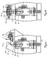
- FIG. 2ashows a first embodiment of a surveying system 50 according to the invention, wherein a scanning module 10 is combined with a surveying instrument 20, eg the theodolite or total station.
- the scan module 10corresponds to a module 10 according to the invention, as in FIG. 1a shown with mirror 11, protractor 13, motor 14, rotation axis 12, laser module 15 and camera 16.
- FIG. 1ashown with mirror 11, protractor 13, motor 14, rotation axis 12, laser module 15 and camera 16.
- the entire upper part of the surveying device 20, the structure 20a designed to receive the scanning module 10,can at the same time at a lower speed about the vertical pivot axis 22 relative to the base 20b of the Surveying device 20 pivoted or rotated. This can be effected by a motor 26 arranged in the surveying instrument 20.
- a laser beam 60can be emitted by the laser module 15, which is guided via an optical beam guiding element 17 onto the mirror 11 and from there, for example, to the measuring point.
- the laser beam 60its reflection on a surface and the detection with the detector, a distance measurement to the measuring point on the surface can thus be carried out.
- the coordinates of the measurement pointcan be calculated from the measured distance and from the vertical angle or rotation angle detected by the angle sensor 13 and a horizontal angle or swivel angle determined by an angle sensor 24 arranged in the swivel device 20.
- the surveying instrument 20also has a targeting unit 30, which can be pivoted or rotated about a second vertical axis 21, in particular a telescope.
- the pivoting of the target unit 30can be effected by means of a further motor 25, wherein a further pivot angle with an angle measuring sensor 23 can be measured.
- FIG. 2bshows a second embodiment of the inventive surveying system 50 with essay scanner 10 and surveying device 20.
- the telescope 30 of the surveying instrument 20can be aligned upward, substantially parallel to its vertical axis 22 and held or locked by means of the locking device 19 in this position.
- a laser beam 60from the laser emitter 27 in the telescope 30 via an optical deflection element 29 in the telescope 30 on an optical beam guide element 17a in the attachment scanner 10 and from there on the mirror 11 and optionally in Another consequence to be directed to the measuring point.
- the mirror 11 of the attachment scanner 10rotates at high speed about the rotation axis 12.
- the structure 20a of the surveying device 20can simultaneously pivot or rotate about the vertical axis 22 at a lower speed.
- the coordinates of the measuring pointcan be calculated from the measured distance and from the angle of rotation detected by the angle sensor 13 and the angle of rotation determined by the angle sensor 24.
- the rotation angle, tilt angle and distances for a respective measuring pointare linked, for example, by means of a processing unit provided on the measuring system 50.
- the image field of the camera 28 of the surveying instrument 20can be aligned with the measuring point via the elements 17 or 29 and 17a as well as the mirror 11 and image data can be acquired.
- FIGS 2c and 2dshow a third and a fourth embodiment of the inventive surveying system 50, each with a surveying device 20 and a scanning module 10 according to the embodiments according to Figures 1c and 1d ,
- Both embodiments of the measuring system 50use a laser beam 60, which is emitted by a beam source 27, in particular a laser diode, of the target unit 30 and guided into the scan module 10.
- a steel passage unit 9is provided in each case.
- the steel passage unit 9may be formed, for example, as a mirror protector or as a means of enlarging the field of view of the camera 28.
- the beam 60can be directed by means of a beam deflection element 17b onto the mirror 11 or onto the polygon mirror 11a and directed onto a surface to be measured.
- a beam deflection element 17bonto the mirror 11 or onto the polygon mirror 11a and directed onto a surface to be measured.
- Figure 2cwill the Laser beam 60 thereby emitted eccentrically to the pivot axis 22 from the mirror 11, wherein a laser plane can be generated, which is parallel to the axis 22.
- the respective angles and the distancewhich are detected at the same time or in defined, mutually assignable time intervals, can be linked.
- This detectioncan, for example, in the embodiment according to FIG. 2a be controlled by the surveying device by at the time of measuring the horizontal angle with the angle sensor 26 via a data interface, a trigger signal to the attachment scanner 10 is sent, which there triggers the measurement of the vertical angle with the angle sensor 13 and the distance.
- the attachment scanner 10can send a trigger signal to the surveying instrument 20 and initiate a simultaneous triggering there within a certain time interval of the horizontal angle measurement.
- the trigger signalcan be transmitted continuously, for example at each point measurement or at certain angular positions, for example once per revolution of the mirror 11, in particular in its nadir position.
- the measured datacan be interpolated between the trigger signals.
- the measurement data (vertical angle and / or distance) determined by the scan module 10can be transmitted to the surveying device 20 via a data interface. There they can be stored together with a determined by the surveying device 20 horizontal angle. In particular, in a control and processing unit of the surveying device 20 from the Angles and the distance point coordinates are calculated and stored.
- the transmission of the horizontal angle from the surveying device 20 to the attachment scanner 10is conceivable. There they can be stored together with the vertical angle and the distance on a memory module or calculated from it with a corresponding control and processing unit of the attachment scanner 10 point coordinates. If the horizontal angle is e.g. detected and transmitted at a lower measuring rate, the measured angles can be interpolated in the processing unit so that only a comparatively small number of angle values have to be transmitted from the surveying device 20 to the attachment scanner 10, e.g. only one value per vertical revolution of the mirror 11 or polygon mirror 11a. Furthermore, prior to data transmission or storage, compression, e.g. by filtering, measuring data or point coordinates.
- the angle sensor of the fast axis 12is the trigger source. In this case it is sufficient to store only the sequence of distance measurements with the slower axis 22 measurement angles. From such a greatly reduced sequence of measured values, the point positions and the associated point cloud can be generated.
- the horizontal angle of the surveying device 20 and the vertical angle and the distance from the attachment scanner 10can be transmitted to an external processing unit, for example to a mobile remote control, which is neither in the surveying device 20 nor in the attachment scanner 10.
- a controllermay be via a wired connection, by radio (e.g., Bluetooth or WLAN), and / or via an optical, inductive, or capacitive interface.
- radioe.g., Bluetooth or WLAN
- suitable transmitting and receiving unitscan be provided on the individual components of the inventive surveying system.
- the power supply of the attachment scanner 10can also be done by an integrated battery or by the surveying device 20 by means of electrical contact.
- an external orientation of the scanning module 10can be determined.
- the scanning module 10can be mounted on the surveying device 20 at a defined position (thus three translation parameters are known) as well as in a defined orientation (with which three rotational parameters are known).
- the surveying device 20may also measure in a measuring environment, in particular by aiming at target points with known coordinates, whereby the position and orientation of the surveying device 20 is known.
- a deviation from the defined position or orientationcan be detected by sensors and taken into account in, for example, the calculation of the coordinates of the measuring points.
- An assembly in a defined position and / or orientationcan in this case be realized for example by a mechanical fastening or centering device, whereby a high position accuracy can be made possible.
- a "scanning" with the surveying device 20can also take place at the same time.
- the telescope 30can rotate about the horizontal axis 21 at a comparatively low speed.
- the horizontal anglecan be measured with the angle sensor 24 and the vertical angle with the angle sensor 23 - the distance can be determined by means of laser module 27. From these measured data, the coordinates of measuring points can be calculated, which in sum can form a point cloud.
- the image acquisitioncan take place by means of a camera 28 provided on the surveying device 20.
- the telescope 30 of the surveying device 20can pivot or rotate about its horizontal axis 21 at a lower speed.
- the built-in telescope camera 28on-axis camera, ie, the camera 28 detects an image corresponding to the orientation of the laser beam 60, in particular coaxially
- imagescan be recorded and simultaneously the horizontal angle and the vertical angle of the telescope 30 are detected. Due to these angles, the image data can be linked to the scan data in the case of a known position and orientation of the attachment scanner 10.
- the surveying system 50with be equipped an overview camera
- the overview camerahas a larger field of view compared to the camera 28 and thus can capture a larger area of a measurement environment.
- the output of the images acquired therebycan, in particular, offer a user added value with regard to the orientation and targeting of targets in the field.
- FIG. 3is a surveying device 20 with scan module 10 according to the embodiment in FIG. 2a wherein the attachment scanner 10 is provided with an additional optical element 31, eg lens or filter, in order to ensure an optical imaging suitable for determining a position of a laser spot on the camera 16.
- distance measuring sensors 32are provided for determining position and orientation parameters. If the distance of the attachment scanner 10 from the surveying device 20 at at least three different positions (which are not on a straight line) detected with such sensors 32, a vertical distance and the longitudinal and transverse inclination of the scan module 10 can be derived from these measurements.
- Additional parameterscan be determined by directing the laser beam 60 from the surveying device 20 via the mirror 11 and the beam guiding element 17 onto the camera 16, which may have a position-sensitive sensor, of the scanning module 10.
- the telescope 30 of the surveying deviceis oriented upward parallel to the vertical axis 22 and the mirror 11 of the attachment scanner 10 downward.
- the parametersmay be derived from a detected position of the laser spot in a captured image of the position-sensitive sensor.
- the laser beam 60be imaged by the laser module 15 of the attachment scanner 10 on the camera sensor 28 of the surveying device 20 and derived from this position of the laser point offset parameters and angle parameters.
- the camera sensor 28can also be executed position-sensitive and evaluated.
- the angular deviation with the angle sensor 23and taken into account, for example, in a coordinate calculation.
- calibration parameters of the surveying instrument 20e.g., boresight error and / or tilt axis error corrections
- attachment scanner 10may be included in the calculation.
- the attachment scanner 10may be equipped with a tilt sensor, which detects the inclination in the longitudinal and transverse directions with respect to the gravitational field. This can be used to correct the measurements of the attachment scanner with respect to the deviation of the pivot axis (vertical axis) from a perpendicular direction.
- a relative inclination of the attachment scanner 10 in relation to the surveying device 20can be calculated.
- a horizontal pivoting of the attachment scanner 10 in relation to the surveying device 20can also by scanning a distinctive structure, such as a vertical house edge, by the attachment scanner 10th on the one hand and by the surveying device 20 on the other hand, wherein the difference angle can be determined based on a horizontal offset of the two thereby obtainable point clouds.
- the attachment scanner 10can also be equipped with a storage module so that the acquired measurement data can be stored directly in the attachment scanner.
- the measurement data of the surveying device 20can be stored on a memory arranged there.
- the synchronization of the attachment scanner 10 and the surveying device 20can take place by means of a trigger signal, which is transmitted from the surveying device 20 to the attachment scanner 20 (or vice versa).
- the synchronizationcan be carried out on the basis of a time signal received in each case with the surveying device 20 and the attachment scanner 10, wherein the two components are each assigned a time receiver.
- the synchronizationcan also be carried out by two GPS receivers which each receive the GPS time, wherein in each case a GPS receiver on the surveying device 20 and attachment scanner 20 is arranged.
- the detected time signalscan each be linked to measured values (for example, a time stamp can be assigned to the measured data), and a subsequent assignment of the measured values can be made by means of the link.
- FIG. 4ashows a scanning module 10 with a surveying instrument 20, wherein also a mechanical locking or centering of the two components, in particular in conjunction with the Figures 4b and 4c , is shown.
- the beam exit end 33, in particular the lens, of the telescope 30is thereby in its illustrated orientation of the Locking device 19 is received such that a lateral displacement caused thereby, which is made possible by the appropriate design of the fastening devices 18, a centering of the attachment scanner 10 relative to the surveying instrument 20 causes.
- a locking device 19is shown in which the attachment scanner 10 is locked with a coarse positioning relative to the beam exit end 33 and a remaining offset to a desired position by distance sensors 34 detected and calculated can be taken into account in the coordinate determination of the measuring point.
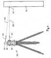
- FIG. 5is a measuring operation with an inventive measuring system 50, in particular for the calibration of the system 50 shown.
- parameterscan be determined which, for example, describe mechanical deviations from a desired geometry and are used to calculate compensations or corrections of the measured values.
- Internal calibration parameterssuch as the angle of the mirror 11 in relation to its axis of rotation 12 or the angle of incidence of the laser beam 60 on the mirror 11 can generally be determined after the production of the scanning module 10. These parameters can be checked after longer time intervals of use of the device with appropriate procedures and corrected if necessary, to ensure high precision of the system 50 can.
- the measurements described belowcan also serve to determine an external orientation of the attachment module 10 in relation to the surveying device 20, in particular in combination with measurement by additional sensors.
- the calibration parameterscan be determined-usually by means of a compensation calculation.
- the surveying device 20are aligned with a target point 41 on an object 70 of known distance. From the known distance and from the angles detected with the angle sensors 23 and 24, a reference aiming direction 42 in the coordinate system of the surveying device 20 can be determined.
- the mirror 11can be aligned with the point 41 marked by a laser beam 40 such that it is imaged as a laser spot in the image of the camera 16 of the scanning module 10.
- a direction 43can be determined.
- a determination of the calibration parameterscan be made by a comparison of the reference directions 42 and the directions 43 with multiple points, wherein the number and the spatial distribution of the point positions to be determined depends on the parameters to be determined.
- the surveying device 20is rotated horizontally by 180 ° with the attachment scanner 10 and then the telescope 30 of the surveying device 20 and the mirror 11 of the attachment scanner 10 vertically rotated such that the same point 41 in the second Circle position can be measured.
- the methodcan also be reversed by the laser beam 60 of the attachment scanner 10 a point 41 marked and this is detected by the camera 28 in the surveying device 20.
- a distance measurementcan be carried out by means of the laser module 27. From the distance and the angles determined by the angle sensors 23 and 24, the coordinates of this point 41 in the coordinate system of the surveying device 20 can be determined. From these coordinates, a reference targeting direction 43 for the attachment scanner 10 can be derived.
- the measurements required for the calibrationcan be carried out manually in a modified form.
- the laser beam 60 of the attachment scanner 10can be aligned to a significant point 41, for example a target mark.
- the anglesare measured with the angle sensors 13 and 24 and thus the direction 43 is determined.
- the alignment of the telescope 30can be done by bringing the laser beam 40 to coincide with the significant point 41, eg the target mark, or by conventional aiming by means of a crosshair.
- Calibration parameters related to the distance measurement of the attachment scanner 10, eg, distance offset and / or distance scaling,may be based on measurements of the distance at equal points in different distances with the surveying device 20 and the attachment scanner 10 are determined.
- the scan module 10can also be pivoted or rotated by means of a motorized swivel device 80.
- the Figures 6a and 6beach show a further embodiment of a surveying system 50 according to the invention with a pivoting device 80 and a scanning module 10 FIG. 6a an attachment scanner 10 is shown with a first embodiment of a pivoting device 80.
- the device 80has a lower base 80b and a pivotable about the vertical axis 81 upper structure 80a, wherein the pivoting can be done by a motor 83 and the pivoting angle can be detected with an angle sensor 82.
- FIG. 6bA second embodiment for the motorized pivot 80 is shown in FIG. 6b shown.
- Thisis additionally equipped with a laser module 84, a camera 85 and an optical deflecting element 86.
- a scanning process with these two embodimentscan analogously to the embodiments according to FIGS. 2a and 2b respectively.
- Both versionscan additionally be equipped with a, in particular two-dimensional, inclination sensor 87, a magnetic compass, a display, in particular a touch-sensitive display, and / or a detachable operating element.
- FIG. 7shows a further embodiment of an inventive surveying system 50 with pivoting device 80, scan module 10 and an attached GNSS unit or GNSS antenna 90.
- the essay scanner 10can be equipped with attachment devices 18a for mounting the GNSS antenna 90 for this purpose.
Landscapes
- Engineering & Computer Science (AREA)
- Physics & Mathematics (AREA)
- General Physics & Mathematics (AREA)
- Radar, Positioning & Navigation (AREA)
- Remote Sensing (AREA)
- Computer Networks & Wireless Communication (AREA)
- Electromagnetism (AREA)
- Optical Radar Systems And Details Thereof (AREA)
- Length Measuring Devices By Optical Means (AREA)
Description
Translated fromGermanDie Erfindung betrifft ein Vermessungssystem mit einem Vermessungsgerät und einem Scanmodul nach dem Oberbegriff des Anspruchs 1, ein erfindungsgemässes Scanmodul nach Anspruch 8, ein Vermessungsgerät nach Anspruch 13 sowie ein Scanverfahren nach Anspruch 14 und ein Computerprogrammprodukt nach Anspruch 15.The invention relates to a surveying system with a surveying device and a scanning module according to the preamble of
Zur Erfassung von Objekten oder Oberflächen werden häufig Verfahren verwendet, welche die Topographie einer Struktur, wie z.B. eines Bauwerks, sukzessive abtasten und dabei aufnehmen. Eine solche Topographie stellt dabei eine zusammenhängende und die Oberfläche des Objekts beschreibende Folge von Punkten oder aber ein entsprechendes Modell oder eine Beschreibung der Oberfläche dar. Ein gängiger Ansatz ist das Abtasten mittels eines Laserscanners, der jeweils die räumliche Position eines Oberflächenpunktes erfasst, indem durch den Laser die Entfernung zum angezielten Oberflächenpunkt gemessen und diese Messung mit den Winkelinformationen der Laseremission verknüpft werden. Aus diesen Entfernungs- und Winkelinformationen kann die räumliche Lage des erfassten Punktes bestimmt und die Oberfläche fortlaufend vermessen werden. In vielen Fällen wird parallel zu dieser rein geometrischen Erfassung der Oberfläche auch noch eine Bildaufnahme durch eine Kamera durchgeführt, welche neben der visuellen Gesamtansicht auch weitere Informationen, z.B. bzgl. der Oberflächentextur, bereitstellt.For detection of objects or surfaces, methods are often used which determine the topography of a structure, such as a surface. of a building, successive scanning and recording. Such a topography represents a coherent sequence of points describing the surface of the object or a corresponding model or description of the surface. A common approach is the scanning by means of a laser scanner, which respectively detects the spatial position of a surface point by moving through the Laser the distance to the targeted surface point measured and this measurement are linked to the angle information of the laser emission. From this distance and angle information, the spatial position of the detected point can be determined and the surface can be measured continuously. In many cases, parallel to this purely geometrical detection of the surface, an image acquisition is also performed by a camera which, in addition to the overall visual view, also contains further information, e.g. regarding the surface texture.
So wird beispielsweise in der
Daneben können scannende Funktionen in verschiedene andere Geräte als Zusatzfunktionen integriert werden. Aus der
Andere Verfahren verwenden mobile Systeme, die eine zu erfassende Struktur durch eine Bewegung des Scannersystems abtasten bzw. die Abtastung unterstützen oder ergänzen. Solche Systeme eignen sich besonders zur Erfassung von linearen oder linear befahrbaren Strukturen, wie beispielsweise Gleisanlagen, Strassen, Tunnelsysteme oder Flugfelder.Other methods use mobile systems that scan a structure to be detected by a movement of the scanner system or support the sampling or supplement. Such systems are particularly suitable for detecting linear or linearly drivable structures, such as track systems, roads, tunnel systems or airfields.
Durch solche Erfassungsvorgänge des Stands der Technik werden Bilder bzw. topographische Daten bereitgestellt, die im Wesentlichen die Information über die räumliche Verteilung oder Anordnungsbeziehung von Oberflächenpunkten repräsentieren. Gegebenenfalls erlauben zusätzlich aufgenommene Bilder die Ableitung weiterer Informationen. Damit sind die Struktur und der Verlauf der Oberfläche vergleichsweise gut rekonstruierbar. Nachteilig sind jedoch die fehlenden qualitativen Angaben über die Art und Beschaffenheit der Oberfläche, insbesondere in Hinblick auf die innere Struktur oder Zusammensetzung. So erlauben parallel zur Abtastung aufgenommene Bilder zumeist die Identifikation unterschiedlicher Helligkeitswerte. Ferner beschreibt die
Derartige Laserscanner nach dem Stand der Technik befähigen einen Benutzer grosse Oberflächen und Objekte mit einem relativ geringen Zeitaufwand - in Abhängigkeit einer gewünschten Punkt-Zu-Punkt-Auflösung - vollständig und gegebenenfalls mit zusätzlichen Objektinformationen zu erfassen, jedoch genügt die Genauigkeit der dabei ableitbaren Punktkoordinaten nicht den hohen geodätischen Genauigkeitsstandards, wie diese beispielsweise für moderne Vermessungsgeräte, insbesondere für Totalstationen oder Thoedoliten, etabliert sind.Such prior art laser scanners enable a user to acquire large surfaces and objects with a relatively small amount of time - depending on a desired point-to-point resolution - completely and optionally with additional object information, but the accuracy of the point coordinates derived thereby is insufficient the high geodetic accuracy standards, such as those for modern surveying equipment, especially for total stations or thedolites, are established.
Moderne Totalstationen weisen in der Regel eine kompakte und integrierte Bauweise auf, wobei meist koaxiale Distanzmesselemente sowie Rechen-, Steuer- und Speichereinheiten in einem Gerät vorhanden sind. Abhängig von der Ausbaustufe der Totalstation können zudem eine Motorisierung der Anziel- bzw. Visiereinrichtung sowie - im Fall der Verwendung von Retroreflektoren (etwa eines Rundum-Prismas) als Ziel-Objekte - Mittel zur automatischen Zielsuche und -verfolgung integriert sein. Als Mensch-Maschine-Schnittstelle kann die Totalstation eine elektronische Anzeige-Steuereinheit - im Allgemeinen eine Mikroprozessor-Recheneinheit mit elektronischen Datenspeichermitteln - mit Display und Eingabemitteln, z.B. einer Tastatur, aufweisen. Der Anzeige-Steuereinheit werden die elektrosensorisch erfassten Messdaten zugeführt, sodass die Position des Zielpunkts durch die Anzeige-Steuereinheit ermittelbar, optisch anzeigbar und speicherbar ist. Aus dem Stand der Technik bekannte Totalstationen können weiters über eine Funkdatenschnittstelle verfügen zum Aufbau einer Funkverbindung zu externen Peripheriekomponenten wie z.B. zu einem handhaltbaren Datenerfassungsgerät, welches insbesondere als Datenlogger oder Feldrechner ausgebildet sein kann.Modern total stations usually have a compact and integrated design, with mostly coaxial distance measuring elements and computing, control and storage units are available in a device. Depending on the expansion stage of the total station, a motorization of the sighting or sighting device and - in the case of the use of retroreflectors (such as a wrap-around prism) as target objects - means for automatic target search and tracking can also be integrated. As a human-machine interface the total station can have an electronic display control unit-generally a microprocessor processor with electronic data storage means-with display and input means, eg a keyboard. The display control unit is supplied with the electrosensory measurement data, so that the position of the target point by the display control unit can be determined, visually displayed and stored. Total stations known from the prior art can furthermore have a radio data interface for setting up a radio link to external peripheral components, such as a handheld data acquisition device, which can be configured in particular as a data logger or field computer.
Zum Anvisieren bzw. Anzielen des zu vermessenden Zielpunkts weisen gattungsgemässe geodätische Vermessungsgeräte ein Zielfernrohr, wie z.B. ein optisches Teleskop, als Visiereinrichtung auf. Das Zielfernrohr ist im Allgemeinen um eine vertikale Stehachse und um eine horizontale Kippachse relativ zu einer Basis des Messgeräts drehbar, sodass das Fernrohr durch Schwenken und Kippen auf den zu vermessenden Punkt ausgerichtet werden kann. Moderne Geräte können additiv zum optischen Sichtkanal eine in das Zielfernrohr integrierte und beispielsweise koaxial oder parallel ausgerichtete Kamera zum Anvisieren mit Winkelsekundengenauigkeit aufweisen. Die dabei erfassbaren Bilder oder Bildsequenzen, insbesondere ein Live-Bild, können auf dem Display der Anzeige-Steuereinheit und/oder auf einem Display des zur Fernsteuerung verwendeten Peripheriegeräts - wie z.B. des Datenloggers - dargestellt werden. Die Optik der Visiereinrichtung kann dabei einen manuellen Fokus - beispielsweise eine Stellschraube zur Veränderung der Position einer Fokussieroptik - aufweisen oder über einen Autofokus verfügen, wobei das Verändern der Fokusposition z.B. durch Servomotoren erfolgt. Beispielsweise ist eine solche Visiereinrichtung eines geodätischen Vermessungsgeräts in der
Da Zielobjekte (z.B. die für geodätische Zwecke meist verwendeten Lotstäbe mit Zielmarke wie einem Rundum-Prisma) anhand der Visiereinrichtung trotz der oft bereitgestellten 30-fachen optischen Vergrösserung mit blossem Auge nicht genügend präzise angezielt werden können (d.h. nicht geodätische Genauigkeitsanforderungen entsprechend), weisen gängige Vermessungsgeräte inzwischen standardmässig eine automatische Zielverfolgungs-Funktion für als Ziel-Reflektor dienende Prismen (ATR: "Automatic Target Recognition") auf. Dafür sind gängigerweise eine weitere separate ATR-Lichtquelle - z.B. ein Multimodefaserausgang, die optische Strahlung mit einer Wellenlänge im Bereich von 850 nm emittiert - und ein spezieller, für diese Wellenlänge sensitiver ATR-Detektor (z.B. CCD- oder CMOS-Flächensensor) zusätzlich im Teleskop integriert. Beispielsweise wird in der
Mit derartigen modernen Vermessungsgeräten können die Koordinaten von angemessenen Zielpunkten mit einer sehr hohen geodätischen Präzision bestimmt werden. Nachteilig dabei ist jedoch, dass eine grossflächige Objektvermessung z.B. mit einer Totalstation einen unverhältnismässig hohen Zeitaufwand - verglichen mit einem Messvorgang eines Laserscanners an dem Objekt - bedeutet.With such modern surveying equipment, the coordinates of appropriate target points can be determined with a very high geodetic precision. The disadvantage here is that a large-scale object measurement For example, with a total station a disproportionately high amount of time - compared to a measuring operation of a laser scanner on the object - means.
Es ist daher Aufgabe der vorliegenden Erfindung ein Zusatzgerät bereitzustellen, welches in Zusammenwirken mit einem Basisgerät eine schnellere und verbesserte punktweise Erfassung einer Oberfläche ermöglicht.It is therefore an object of the present invention to provide an attachment which, in cooperation with a base unit, enables a faster and improved point-by-point detection of a surface.
Es ist eine weitere Aufgabe der Erfindung ein verbessertes Messinstrument bereitzustellen, welches neben einer instrumenteigenen hoch präzisen Zielpunktbestimmungsmöglichkeit eine Funktionalität zur schnellen Erfassung einer Vielzahl von Zielpunkten mit - relativ zu einer mehrfachen präzisen Zielpunktbestimmung - kleinem Zeitaufwand ermöglicht.It is a further object of the invention to provide an improved measuring instrument which, in addition to an instrument's own highly accurate target point determination capability, provides functionality for rapidly acquiring a plurality of target points with little time overhead relative to multiple precise target point determination.
Eine weitere Aufgabe der Erfindung ist es, ein Vermessungsgerät nach dem Stand der Technik derart zu erweitern, dass dem Vermessungsgerät zusätzlich eine Scanfunktionalität bereitgestellt wird.A further object of the invention is to expand a prior art surveying device in such a way that a scanning functionality is additionally provided for the surveying device.
Diese Aufgaben werden durch die Verwirklichung der kennzeichnenden Merkmale der unabhängigen Ansprüche gelöst. Merkmale, die die Erfindung in alternativer oder vorteilhafter Weise weiterbilden, sind den abhängigen Patentansprüchen zu entnehmen.These objects are achieved by the realization of the characterizing features of the independent claims. Features which further develop the invention in an alternative or advantageous manner can be found in the dependent claims.
Ein erfindungsgemässes Vermessungssystem weist ein Vermessungsgerät, insbesondere Totalstation, Theodolit oder Lasertracker, mit einer Basis, einem auf der Basis angeordneten, um eine Schwenkachse schwenkbaren Aufbau, und einer Anzieleinheit auf, insbesondere Ziel-Fernrohr, wobei die Anzieleinheit wenigstens eine eine optische Zielachse definierende Emissionseinheit zur Emission eines ersten Laserstrahls, und eine erste Entfernungsmessfunktionalität zur Messung einer Entfernung zu einem Objekt aufweist. Zudem verfügt das Vermessungsgerät über eine erste Winkelmessfunktionalität zur hochpräzisen Erfassung zumindest eines durch eine relative Schwenkposition des Aufbaus zur Basis definierten Schwenkwinkels. Das Vermessungssystem weist ausserdem eine Steuerungs- und Verarbeitungseinheit zur Datenverarbeitung und zur Steuerung des Vermessungssystems auf.A surveying system according to the invention comprises a surveying device, in particular total station, theodolite or laser tracker, with a base, a structure arranged on the base, pivotable about a pivot axis, and a target unit, in particular a target telescope, wherein the target unit has at least one emission unit defining an optical target axis to issue a first Laser beam, and a first distance measuring functionality for measuring a distance to an object. In addition, the surveying device has a first angle measuring functionality for the high-precision detection of at least one pivoting angle defined by a relative pivoting position of the body to the base. The surveying system also has a control and processing unit for data processing and control of the surveying system.
Ferner verfügt das Vermessungssystem über ein Scanmodul mit Befestigungsmitteln zur Befestigung des Scanmoduls an einer mit den Befestigungsmitteln korrespondierenden Aufnahme, mit einem um eine Rotationsachse motorisiert rotierbares Strahlumlenkelement zur Ablenkung eines Scanlaserstrahls, wobei die Rotationsachse in einem aufgenommenen Zustand in einem definierten Winkel relativ zur Schwenkachse steht, insbesondere orthogonal, und mit einer zweiten Winkelmessfunktionalität zur Bestimmung eines Rotationswinkels aus einer Winkelstellung des Strahlumlenkelements. Darüber hinaus weist das Vermessungsgerät eine derart ausgebildete Aufnahme auf, dass das Scanmodul durch ein Zusammenwirken der Aufnahme mit den Befestigungsmittel auf dem Vermessungsgerät in einer definierten Positionierung modulartig befestigbar ist. Die Steuerungs- und Verarbeitungseinheit ist zudem derart ausgebildet, dass der jeweilige Rotationswinkel, der jeweilige Schwenkwinkel und die jeweilige Entfernung für einen Punkt auf dem Objekt verknüpft werden, sodass durch die Verknüpfung jeweils eine Punkt-Position definiert ist, und eine eine Anzahl der Punkt-Positionen aufweisende Punktwolke erzeugbar ist.Furthermore, the surveying system has a scanning module with fastening means for fastening the scanning module to a mounting with the fastening means, with a rotatable about a rotation axis rotatable Strahlumlenkelement for deflecting a Scanlaserstrahls, the rotation axis is in a recorded state at a defined angle relative to the pivot axis, in particular orthogonal, and with a second angle measuring functionality for determining a rotation angle from an angular position of the Strahlumlenkelements. In addition, the surveying device has a receptacle designed in such a way that the scanning module can be fastened in a modular manner by a cooperation of the receptacle with the fastening means on the surveying device in a defined positioning. The control and processing unit is also designed such that the respective rotation angle, the respective pivoting angle and the respective distance are linked for a point on the object, so that by the linkage in each case a point position is defined, and a number of points Positioned point cloud can be generated.
Mit einem derartigen Vermessungssystem kann durch die rotierende Bewegung des Umlenkelements, beispielsweise eines Spiegels, und der Ablenkung des darauf auftreffenden Scanlaserstrahls eine Laserebene bzw. eine Laserfläche, insbesondere höherer Ordnung, definiert werden. Dadurch dass das Scanmodul, in welchem der Spiegel rotiert, mittels des als Schwenkvorrichtung dienenden Vermessungsgeräts um eine zweite Achse geschwenkt wird, kann die Laserebene nun fortlaufend versetzt werden und somit eine Umgebung fortlaufend mit dem emittierten Laserstrahl abgetastet werden. Mit den beiden Winkelmessern wird zudem zu jedem Punkt, auf dem der Laserstrahl auftrifft, reflektiert wird und mit einem Detektor zum Zweck der Distanzmessung detektiert wird, eine Emissionsrichtung des Laserstrahls zum einen relativ zum Scanmodul und zum zweiten relativ zur Basis des Vermessungsgeräts bestimmt. Die Distanzmessung kann dabei z.B. nach dem Phasenmessprinzip oder mittels einer Laufzeitbestimmung durchgeführt werden. Durch die mittels der Steuerungs- und Verarbeitungseinheit vorgenommene Verknüpfung von jeweils zu einem Punkt gehörenden gemessenen Winkel- und jeweiligen Distanzgrössen können Wertearrays erzeugt werden, wobei jedes Array eine Koordinate des gemessenen Punkts repräsentiert. Beispielsweise können gleichzeitig bzw. innerhalb eines bestimmten Zeitintervalls bzw. in definierten Zeitabständen erfasste Winkel und Distanzen verknüpft werden. Eine die vermessene Umgebung verkörpernde Punktwolke kann weiters durch ein Zusammenfügen einer Vielzahl derartiger Wertearrays erzeugt werden. Erfindungsgemäss ist das Scanmodul derart ausgebildet, dass es von der Schwenkeinheit abnehmbar bzw. darauf modulartig mittels spezifisch dafür vorgesehener Befestigungsmittel aufsetzbar ist. Dabei kann beispielsweise ein Stativ mit einer mit einem Dreibein fest verbundener Basis und einem auf der Basis angebrachten, relativ dazu schwenkbaren Aufbau als Schwenkvorrichtung für das erfindungsgemässe Vermessungssystem dienen. Zusätzlich können an einer derartigen Vorrichtung Aufnahmen angeordnet sein, die jeweils dafür geeignet sind ein das Scanmodul aufzunehmen, sodass eine definierte Verbindung zwischen den Komponenten entsteht, welche auf einfache Weise wieder lösbar ist. Eine hierfür geeignete Aufnahme und korrespondierende Befestigungsmittel können prinzipiell nach einem Stecker-Steckdosen-Prinzip zusammenwirken und ausgebildet sein.With such a surveying system, a laser plane or a laser surface, in particular of a higher order, can be defined by the rotating movement of the deflecting element, for example a mirror, and the deflection of the scanning laser beam impinging thereon. By virtue of the fact that the scanning module, in which the mirror rotates, is pivoted about a second axis by means of the surveying device serving as a swiveling device, the laser plane can now be displaced continuously and thus an environment can be scanned continuously with the emitted laser beam. In addition, with the two protractors, an emission direction of the laser beam relative to the scan module and to the second relative to the base of the surveying apparatus is determined at each point on which the laser beam impinges and is detected by a detector for the purpose of distance measurement. The distance measurement can be carried out, for example, according to the phase measurement principle or by means of a transit time determination. By means of the linking of respective measured angle and respective distance variables belonging to one point by means of the control and processing unit, value arrays can be generated, each array representing a coordinate of the measured point. For example, angles and distances detected simultaneously or within a specific time interval or at defined time intervals can be linked. A point cloud embodying the measured environment may be further generated by assembling a plurality of such value arrays. According to the invention, the scanning module is designed such that it can be removed from the pivoting unit or placed thereon in a modular manner by means of fastening means provided specifically for this purpose. Here, for example, a tripod with a a tripod fixed base and a mounted on the base, relative thereto pivotable structure serve as a pivoting device for the inventive surveying system. In addition, recordings can be arranged on such a device, each of which is suitable for receiving the scan module, so that a defined connection arises between the components, which can be released again in a simple manner. A suitable receptacle and corresponding fastening means can in principle cooperate and be designed according to a plug-socket principle.
Insbesondere kann das Scanmodul erfindungsgemäss eine Strahldurchtrittseinheit aufweisen und die Anzieleinheit derart ausrichtbar sein, dass der erste Laserstrahl in einem Einkoppelzustand vermittels der Strahldurchtrittseinheit in das Scanmodul einkoppelbar ist und vermittels des Strahlumlenkelements um die Rotationsachse als Scanlaserstrahl rotierend ablenkbar ist, insbesondere wobei ein am Objekt reflektierte Scanlaserstrahl vermittels der Strahldurchtrittseinheit aus dem Scanmodul auskoppelbar ist.In particular, according to the invention, the scanning module can have a beam passage unit and the targeting unit can be aligned in such a way that the first laser beam can be coupled into the scanning module by means of the beam passage unit and can be rotationally deflected by the beam deflecting element about the axis of rotation as a scanning laser beam, in particular a scan laser beam reflected at the object can be decoupled from the scan module by means of the beam passage unit.
Das Scanmodul des Vermessungssystem kann erfindungsgemäss zudem eine derart ausgebildete Erfassungseinheit aufweisen, dass eine Auftreffposition des im Einkoppelzustand mittels des Strahlumlenkelements auf die Erfassungseinheit umlenkbaren ersten Laserstrahls auf der Erfassungseinheit erfassbar ist, wobei in Abhängigkeit der Auftreffposition ein eine relative Positionierung des Scanmoduls zum Vermessungsgerät angebender Positionierungsparameter erzeugbar ist, insbesondere wobei mittels des Positionierungsparameters die Punkt-Positionen korrigierbar sind.According to the invention, the scanning module of the surveying system can also have a detection unit designed in such a way that an incident position of the first laser beam which can be deflected onto the detection unit in the coupling-in state can be detected on the detection unit, wherein a positioning parameter indicative of relative positioning of the scanning module relative to the surveying device can be generated as a function of the impact position is, in particular wherein by means of the positioning parameter, the point positions are correctable.
Bei der Anordnung des Scanmoduls auf dem Vermessungsgerät, wobei die Befestigungsmittel des Scanmoduls mit den Aufnahmen des Vermessungsgeräts lösbar verbunden sind, kann der mittels der Anzieleinheit emittierbare erste Laserstrahl durch ein definiertes Ausrichten der Anzieleinheit derart ausgerichtet werden, dass der Strahl auf die Strahldurchtrittseinheit gerichtet ist und durch diese in das Scanmodul transmittiert bzw. eingekoppelt wird. Die Strahldurchtrittseinheit kann hierfür z.B. mit einem spezifischen optisch transparenten Material ausgebildet sein, sodass jeweils diejenige Strahlung der Emissionseinheit des Vermessungsgeräts mit einer spezifischen Wellenlänge durch das Material transmittiert wird. Die Laserstrahlung wird dann, beispielsweise mittels Spiegel, Prismen und/oder Linsen, zum Strahlumlenkelement geführt und dort in einem bestimmten Winkel abgelenkt und aus dem Scanmodul emittiert. Durch die Rotation des Strahlumlenkelements (und durch das gleichzeitige Schwenken des Vermessungsgeräts) und das Aussenden, das Reflektieren an einem Objekt und das Empfangen des Strahls kann so ein Scannen des Objekts erfolgen. Der reflektierte Strahl kann somit korrespondierend mit einem Emissionsstrahlgang aus dem Scanmodul ausgekoppelt und in das Vermessungsgerät eingekoppelt werden und somit wieder am Vermessungsgerät empfangen und die Entfernung zum Objekt somit mittels der Entfernungsmessfunktionalität der Anzieleinheit gemessen werden.In the arrangement of the scanning module on the surveying device, wherein the fastening means of the scanning module are detachably connected to the recordings of the surveying device, the emissive by means of the target unit first laser beam can be aligned by a defined alignment of the targeting unit such that the beam is directed to the beam passage unit and is transmitted or coupled by them into the scan module. The beam passage unit can be used for this purpose e.g. be formed with a specific optically transparent material, so that in each case that radiation of the emission unit of the surveying device is transmitted with a specific wavelength through the material. The laser radiation is then guided, for example by means of mirrors, prisms and / or lenses, to the beam deflecting element where it is deflected at a certain angle and emitted from the scanning module. As a result of the rotation of the beam deflection element (and the simultaneous pivoting of the surveying device) and the emission, reflection on an object and the reception of the beam, the object can be scanned in this way. The reflected beam can thus be decoupled from the scan module corresponding to an emission beam path and coupled into the surveying device and thus again received at the surveying device and the distance to the object thus measured by means of the distance measuring functionality of the target unit.
Erfindungsgemäss können ausserdem durch das Erfassen des von dem Vermessungsgerät emittierten Laserstrahls mit einer spezifischen Erfassungseinheit auf Seiten des Scanmoduls, z.B. mit einem Flächensensor (z.B. CMOS oder CCD-Array), Parameter ermittelt werden, mit welchen eine Bestimmung der Positionierung des Scanmoduls auf dem Vermessungsgerät vollzogen werden kann. Beispielsweise kann aus einer Ablage des auftreffenden Laserstrahls aus einem Bildzentrum der Erfassungseinheit - in Abhängigkeit der Richtung und Entfernung vom Zentrum - eine Information bezüglich der Position und Orientierung des Scanmoduls relativ zum Vermessungsgerät gewonnen werden. Die dabei ermittelten Parameter oder erzeugten Messsignale können der Steuerungs- und Verarbeitungseinheit zur Bestimmung von z.B. Korrekturparametern zur Verfügung gestellt werden. Diese wiederum können zudem zur allfälligen Kompensation von Messwerten herangezogen werden oder können einem Benutzer graphisch, z.B. auf einem Display, angezeigt werden, sodass dieser eine Positionskorrektur der beiden Komponenten (Vermessungsgerät und Scanmodul) relativ zueinander vornehmen kann.According to the invention, by detecting the laser beam emitted by the surveying device with a specific detection unit on the side of the scanning module, eg with an area sensor (eg CMOS or CCD array), parameters can be determined with which a determination of the Positioning of the scan module on the surveying device can be completed. For example, from a storage of the incident laser beam from an image center of the detection unit - depending on the direction and distance from the center - information regarding the position and orientation of the scanning module relative to the surveying device can be obtained. The parameters ascertained or generated measuring signals can be made available to the control and processing unit for determining eg correction parameters. These in turn can also be used for the compensation of measured values or can be displayed to a user graphically, for example on a display, so that the latter can perform a position correction of the two components (surveying device and scanning module) relative to one another.
Ferner kann das Scanmodul erfindungsgemäss eine Strahlquelle zur Emission eines zweiten Laserstrahls als Scanlaserstrahl aufweisen und der Scanlaserstrahl vermittels des Strahlumlenkelements um die Rotationsachse rotierend ablenkbar sein, insbesondere wobei das Scanmodul eine zweite Entfernungsmessfunktionalität zur Entfernungsmessung, insbesondere mittels des Scanlaserstrahls, aufweist.Furthermore, according to the invention, the scanning module can have a beam source for emitting a second laser beam as a scanning laser beam and the scanning laser beam can be rotationally deflected about the rotational axis by means of the beam deflecting element, in particular wherein the scanning module has a second distance measuring functionality for distance measurement, in particular by means of the scanning laser beam.
Durch die Anordnung dieser Strahlquelle z.B. im Scanmodul kann der Laserstrahl zum Scannen eines Objekts unabhängig von dem Vermessungsgerät emittiert werden und ein Einkoppeln des Stahls in das Scanmodul muss nicht vorgenommen werden, um die Scanfunktionalität bereitzustellen. Das Scanmodul kann zudem über eine weitere Entfernungsmessfunktionalität verfügen und durch ein Empfangen des reflektierten Scanstrahls am Scanmodul eine Entfernung zum Objekt messbar sein. In dieser Konfiguration kann somit sowohl der Rotationswinkel als auch die Entfernung seitens des Scanmoduls ermittelt werden. Der Schwenkwinkel kann mittels des Vermessungsgeräts bestimmt werden.By arranging this beam source, for example in the scan module, the laser beam can be emitted for scanning an object independently of the surveying device and coupling of the steel into the scan module need not be undertaken to provide the scan functionality. The scan module may also have further ranging capability and receive a reflected scan beam on the scan module Distance to the object be measurable. In this configuration, both the rotation angle and the distance can be determined by the scan module. The swivel angle can be determined by means of the surveying device.
Im Allgemeinen kann der Schwenkwinkel an eine dem Scanmodul zugeordneten Steuerungs- und Verarbeitungseinheit übermittelt werden und die Verknüpfung, Weiterverarbeitung und/oder Bereitstellung von Schwenkwinkel, Rotationswinkel und Entfernung kann dort erfolgen. Insbesondere können Rotationswinkel und Entfernung an eine dem Vermessungsgerät zugeordnete Steuerungs- und Verarbeitungseinheit übertragen und seitens des Vermessungsgeräts verknüpft und bereitgestellt werden. Weiters können die Daten zur Verknüpfung, Verarbeitung und/oder Bereitstellung einer mobilen oder stationären Einheit, z.B. Arbeitscomputer, Laptop oder Fernbedienung für das System, mit Steuerungs- und Verarbeitungseinheit zur Verfügung gestellt werden. Die Datenübertragung kann ferner kabelgebunden, mittels Funk, WLAN, Infrarot oder via Bluetooth erfolgen.In general, the swivel angle can be transmitted to a control and processing unit assigned to the scan module and the linking, further processing and / or provision of swivel angle, rotation angle and distance can take place there. In particular, rotation angle and distance can be transmitted to a control and processing unit associated with the surveying device and linked and provided by the surveying device. Furthermore, the data for linking, processing and / or providing a mobile or stationary unit, e.g. Work computer, laptop or remote control for the system to be provided with control and processing unit. The data transmission can also be wired, by radio, WLAN, infrared or via Bluetooth.
Insbesondere kann das Vermessungssystem mindestens einen Abstandsmesssensor zur Messung eines Abstands zwischen dem Scanmodul und dem Vermessungsgerät im aufgenommenen Zustand zur Erzeugung eines weiteren, die relative Positionierung des Scanmoduls zum Vermessungsgerät angebenden Positionierungsparameters aufweisen.In particular, the surveying system can have at least one distance measuring sensor for measuring a distance between the scanning module and the surveying device in the recorded state for generating a further positioning parameter indicating the relative positioning of the scanning module relative to the surveying device.
Mit einem derartigen Sensor kann eine relative Position des Scanmoduls auf dem Vermessungsgerät präzise bestimmt werden, insbesondere dann wenn zu dieser Positionsbestimmung drei - nicht auf einer Geraden liegende - solche Sensoren vorgesehen sind. So können Abstände zwischen den Komponenten gemessen und aus einem in Bezugsetzen der Abstände beispielsweise eine relative Neigung der Komponenten zueinander bestimmt werden. Ist demnach die Position und Ausrichtung des Vermessungsgeräts bekannt, kann mittels der Sensoren eine eindeutige Bestimmung der Ausrichtung und - bei einer definierten Positionierung des Scanmoduls auf dem Vermessungsgerät - gegebenenfalls der Position des Scanmoduls erfolgen. Dem System können aus diesen Messungen Informationen zur Position und Ausrichtung z.B. in einer definierten Parameterform bereitgestellt und beispielsweise zu Zwecken einer Kompensation oder Anpassung von zu bestimmenden Koordinaten weiterverarbeitet werden, insbesondere seitens der Steuerungs- und Verarbeitungseinheit.With such a sensor, a relative position of the scanning module on the surveying device can be precisely determined, in particular if three such sensors are provided for this position determination-not lying on a straight line. So can distances measured between the components and from a reference to the distances, for example, a relative inclination of the components are determined to each other. Accordingly, if the position and orientation of the surveying device is known, an unambiguous determination of the orientation and, if the positioning of the scanning module on the surveying device is defined, the position of the scanning module can be determined by means of the sensors. From these measurements, the system can be provided with information on the position and orientation, for example in a defined parameter form, and further processed for purposes of compensation or adaptation of coordinates to be determined, in particular by the control and processing unit.
Ausserdem kann das Vermessungssystem erfindungsgemäss eine zumindest zweikomponentige Zentriervorrichtung zur definierten Positionierung des Scanmoduls auf dem Vermessungsgerät aufweisen, wobei eine erste Komponente dem Scanmodul und eine zweite Komponente dem Vermessungsgerät zugeordnet ist, insbesondere wobei eine Positionierungsgenauigkeit mittels Sensoren zur Bestimmung einer relativen Positionierung der ersten zur zweiten Komponente messbar ist.In addition, according to the invention, the surveying system can have an at least two-component centering device for defined positioning of the scanning module on the surveying device, wherein a first component is assigned to the scanning module and a second component to the surveying device, in particular a positioning accuracy by means of sensors for determining a relative positioning of the first to the second component is measurable.
Um das Scanmodul in einer definierten Position und Ausrichtung auf dem Vermessungsgerät oder - im Allgemeinen - auf einer Schwenkvorrichtung mit einem relativ zu einer Basis schwenkbaren Aufbau befestigen zu können, kann eine derartige Zentriervorrichtung in das Vermessungssystem integriert werden bzw. daran angeordnet sein. Durch ein Zusammenwirken der ersten Komponente dieser Zentriervorrichtung mit der Zweiten, wobei jeweils eine der Komponenten dem Scanmodul und die Andere dem Vermessungsgerät bzw. der Schwenkvorrichtung zugeordnet sind, kann bei einer Montage des Scanmoduls auf dem Vermessungsgerät eine hohe Montagepräzision erreicht werden. Zudem können Sensoren vorgesehen sein, mit welchen Abstände der Zentrierkomponenten zueinander und damit eine Zentriergenauigkeit bestimmt werden können. Eine solche Zentriervorrichtung kann beispielsweise aus einem Zapfen als erste Komponente und einer Aufnahme als zweite Komponente, die zur präzisen Aufnahme des Zapfens, insbesondere unter Einhaltung einer definierten Toleranz, ausgestaltet ist, bestehen. An den in einem Zentrierzustand dem Zapfen zugewandten Seiten der Zapfenaufnahme können zudem Sensoren zur Abstandsmessung zum Zapfen angeordnet sein. Eine bekannte, lösbare Präzisionsverbindung mit spielfreier Zwangszentrierung ist als Schnittstelle zum Dreifuss am Theodolitenunterteil bekannt. Die Verbindung des Scanmoduls mit dem Vermessungsgerät kann in einer vergleichbaren Art ausgeführt sein.In order to fix the scanning module in a defined position and orientation on the surveying device or - in general - on a pivoting device with a pivotable relative to a base structure, such a centering device can be integrated into the surveying system or be arranged thereon. By an interaction of the first component of this centering device with the second, wherein each one of the components of the scan module and the other the Assigned surveying device or the pivoting device, a high mounting precision can be achieved when mounting the scanning module on the surveying equipment. In addition, sensors may be provided with which distances of the centering components to one another and thus a centering accuracy can be determined. Such a centering device can for example consist of a pin as a first component and a receptacle as a second component, which is designed for precise recording of the pin, in particular while maintaining a defined tolerance. In addition, sensors for measuring the distance to the pin can be arranged on the sides of the pin receptacle facing the pin in a centering state. A well-known, detachable precision connection with backlash-free positive centering is known as an interface to the tribrach on the theodolite base. The connection of the scanning module to the surveying device can be carried out in a comparable manner.
Ausserdem kann das Vermessungssystem erfindungsgemäss eine Kamera zur Erfassung eines Bildes aufweisen. Mittels dieser Kamera kann ein Bild der zu vermessenden Umgebung bzw. des Objekts aufgenommen werden, wobei im Bild erfasste Informationen zur Charakterisierung des Objekts bzw. dessen Oberfläche herangezogen werden können. Durch eine Verknüpfung der Bildinformation mit den im Scanprozess erzeugten Messdaten können zusätzliche Objekteigenschaften, insbesondere punktuell aufgelöst, abgeleitet und weiterverarbeitet werden. Weiters kann die Kamera derart im Vermessungssystem angeordnet und ausgebildet sein, dass ein Erfassen des Bildes vermittels des Strahlumlenkelements erfolgt, d.h. einfallendes Licht kann mit Hilfe des Strahlumlenkelements auf die Kamera gelenkt werden.In addition, according to the invention, the surveying system can have a camera for capturing an image. By means of this camera, an image of the environment or of the object to be measured can be recorded, wherein information captured in the image can be used to characterize the object or its surface. By linking the image information with the measurement data generated in the scanning process, additional object properties, in particular selectively resolved, can be derived and further processed. Furthermore, the camera can be arranged and configured in the surveying system in such a way that the image is detected by means of the beam deflection element, ie incident light can be directed onto the camera with the aid of the beam deflection element.
Darüber hinaus kann das Strahlumlenkelement durch einen Spiegel, insbesondere durch einen Polygonspiegel, verkörpert sein. Die Ablenkung des Laserstrahls kann somit in Abhängigkeit der Ausgestaltung des Spiegels und seiner relativen Neigung zu einer Einfallrichtung des Laserstrahls in einem definierten Winkel erfolgen. Weiters kann die Umlenkung des Laserstrahls dadurch innerhalb einer vollständigen Umdrehung des Polygonspiegels mehrmalig erfolgen.In addition, the beam deflection element can be embodied by a mirror, in particular by a polygon mirror. The deflection of the laser beam can thus take place in dependence on the configuration of the mirror and its relative inclination to a direction of incidence of the laser beam at a defined angle. Furthermore, the deflection of the laser beam can thereby take place several times within a complete revolution of the polygon mirror.
Erfindungsgemäss kann ausserdem eine Neigung oder Verkippung des Scanmoduls relativ zum Vermessungsgerät mittels eines Abscannens einer markanten Struktur (mit dem Scanmodul und dem Vermessungsgerät) bestimmbar sein, wobei die relative Neigung in Abhängigkeit eines Vergleichs einer mittels des Scanmoduls erzeugten, die markante Struktur repräsentierenden Scanpunktwolke und einer mittels des Vermessungsgeräts erzeugten, die markante Struktur repräsentierenden Vermessungspunktwolke bestimmt wird.According to the invention, an inclination or tilting of the scanning module relative to the surveying device can also be determined by scanning a distinctive structure (with the scanning module and the surveying device), the relative inclination depending on a comparison of a scanning point cloud generated by the scanning module and representing the distinctive structure determined by the surveying device, representing the distinctive structure survey point cloud is determined.
Die Erfindung betrifft weiterhin ein erfindungsgemässes Scanmodul für ein erfindungsgemässes Vermessungssystem mit einem um eine Rotationsachse motorisiert rotierbaren Strahlumlenkelement zur Ablenkung eines Scanlaserstrahls und einer Winkelmessfunktionalität zur Bestimmung eines Rotationswinkels aus einer Winkelstellung des Strahlumlenkelements. Ferner weist das Scanmodul Befestigungsmittel zur Befestigung des Scanmoduls an einer mit den Befestigungsmitteln korrespondierenden Aufnahme auf, wobei das Scanmodul durch ein Zusammenwirken der Befestigungsmittel mit der an einem Vermessungsgerät angeordneten Aufnahme, insbesondere Totalstation, Theodolit oder Lasertracker, auf dem Vermessungsgerät in einer definierten Positionierung modulartig befestigbar ist.The invention further relates to a scanning module according to the invention for a surveying system according to the invention with a beam deflection element rotatable about a rotation axis for deflecting a scanning laser beam and an angle measurement functionality for determining a rotation angle from an angular position of the beam deflection element. Furthermore, the scanning module has fastening means for fastening the scanning module to a receptacle corresponding to the fastening means, wherein the scanning module can be fastened to the surveying device in a defined positioning in a modular manner by cooperation of the fastening means with the receptacle arranged on a surveying device, in particular total station, theodolite or laser tracker is.
Zudem ist das Scanmodul zur Übergabe des Rotationswinkels an eine Steuerungs- und Verarbeitungseinheit gemäss dem erfindungsgemässen Vermessungssystem ausgebildet.In addition, the scanning module for transferring the rotation angle to a control and processing unit according to the inventive surveying system is formed.
Ein solches Scanmodul bzw. ein solcher Aufsatzscanner kann durch die Rotation des Laserstrahls um die Rotationsachse eine Laserebene erzeugen, wobei sowohl der emittierte Laserstrahl als auch ein an einem Objekt reflektierter Strahl mittels des Strahlumlenkelements geführt bzw. entsprechend einer bestimmten Messrichtung von der Strahlquelle zum Objekt und vom Objekt zum Detektor gelenkt werden kann. Durch einen eingebauten Winkelmesssensor können ferner die jeweilige Emissions- und Empfangsrichtung des Strahls bestimmt werden. Werden nun mittels des Laserstrahls Entfernungen zu Punkten gemessen und diese Entfernungen mit den zum Messzeitpunkt vorliegenden Winkeln verknüpft, so können aus jeder Entfernungs-WinkelKombination eine Koordinate des jeweiligen Zielpunktes bestimmt werden und mittels einer Ansammlung bzw. Kumulation dieser Punkte die Punktwolke erzeugt werden. Des Weiteren kann das Scanmodul mit den Befestigungsmitteln auf einer Vorrichtung, insbesondere mittels einer dafür vorgesehenen Aufnahmevorrichtung, platziert und befestigt werden. Mittels dieser Vorrichtung kann das Scanmodul um eine zweite Achse, die senkrecht zur Rotationsachse des Strahlumlenkelements steht, geschwenkt bzw. rotiert werden, wobei damit die Laserebene entsprechend geschwenkt wird und somit eine Erzeugung einer Punktwolke einer durchschwenkten Messumgebung oder eines abgeschwenkten Objekts durchführbar ist. Die seitens des Scanmoduls dabei erzeugten Daten, insbesondere Rotationswinkel, können der Steuerungs- und Verarbeitungseinheit, z.B. einer Totalstation, zur Verknüpfung von Rotationswinkeln mit Schwenkwinkeln und Entfernungen zur Verfügung gestellt werden.By means of the rotation of the laser beam about the axis of rotation, such a scanning module or a scanner scanner can generate a laser plane, wherein both the emitted laser beam and a beam reflected at an object are guided by the beam deflection element or from the beam source to the object and in accordance with a specific measurement direction can be directed from the object to the detector. By a built-angle sensor, the respective emission and reception direction of the beam can be further determined. If distances to points are now measured by means of the laser beam and these distances are linked to the angles existing at the time of measurement, a coordinate of the respective target point can be determined from each distance-angle combination and the point cloud can be generated by means of an accumulation or accumulation of these points. Furthermore, the scanning module can be placed and fastened with the fastening means on a device, in particular by means of a receiving device provided for this purpose. By means of this device, the scanning module about a second axis which is perpendicular to the axis of rotation of the Strahlumlenkelements be pivoted or rotated, whereby the laser plane is pivoted accordingly and thus generation of a point cloud of a durchschwenkten measurement environment or a pivoted object is feasible. The data generated by the scanning module, in particular rotation angles, can be used by the control and processing unit, eg a total station, for Linking rotation angles with swivel angles and distances can be provided.
Ferner kann das Scanmodul erfindungsgemäss eine Strahldurchtrittseinheit zur Einkopplung und/oder Auskopplung des Scanlaserstrahls aufweisen, sodass zumindest der eingekoppelte Scanlaserstrahl vermittels des Strahlumlenkelements um die Rotationsachse rotierend ablenkbar ist. Hierdurch kann ein Laserstrahl von einer körperlich vom Scanmodul getrennten Strahlquelle in das Scanmodul eingestrahlt werden und derart geführt werden, dass der Strahl als Scanlaserstrahl verwendet und mittels des Strahlumlenkelements abgelenkt werden kann. Die Entfernungsmessung zum Objekt kann dabei ebenfalls anhand des eingekoppelten Laserstrahls erfolgen. Dazu kann der am Objekt reflektierte Strahl wiederum seitens des Scanmoduls empfangen, von Strahlumlenkelement abgelenkt und durch die Strahldurchtrittseinheit, die beispielsweise mit optisch transparentem Material ausgebildet ist, ausgekoppelt werden, sodass der ausgekoppelte Strahl von einem Detektor zum Zweck der Entfernungsmessung erfasst wird.Furthermore, according to the invention, the scanning module can have a beam passage unit for coupling and / or decoupling the scan laser beam so that at least the coupled scanning laser beam can be deflected in a rotating manner about the rotation axis by means of the beam deflection element. In this way, a laser beam from a beam source physically separate from the scan module can be irradiated into the scan module and guided in such a way that the beam can be used as a scan laser beam and deflected by means of the beam deflection element. The distance measurement to the object can also be done on the basis of the coupled laser beam. For this purpose, the beam reflected by the object can again be received by the scanning module, deflected by the beam deflection element and coupled out by the beam passage unit, which is formed, for example, with optically transparent material, so that the coupled-out beam is detected by a detector for the purpose of distance measurement.
Insbesondere kann das Scanmodul erfindungsgemäss eine Erfassungseinheit zur Erfassung des Scanlaserstrahls aufweisen, wobei die Erfassungseinheit eine Entfernungsmessfunktionalität zur Entfernungsmessung zu einem Objekt und/oder einen positionssensitiven Sensor zur Bestimmung einer Auftreffposition des Scanlaserstrahls auf einem Sensor aufweist. Ausserdem kann das Scanmodul erfindungsgemäss eine Strahlquelle zur Emission des Scanlaserstrahls aufweisen und der Scanlaserstrahl vermittels des Strahlumlenkelements um die Rotationsachse rotierend ablenkbar sein. Mit diesen Ausführungen des Scanmoduls kann zum einen der Strahl unabhängig von externen Strahlquellen emittiert werden und zum zweiten die Entfernungsmessung ebenfalls unabhängig von zusätzlichen Entfernungsmessern bestimmt werden. In Kombination dieser Ausführungen können sowohl die Rotationswinkel als auch die Entfernungen für Punkte am Objekt mit dem Scanmodul bestimmt werden. Die Strahlquelle kann dabei einen Laserstrahl derart emittieren, dass dieser auf das Strahlumlenkelement trifft um von dort auf das Objekt umgelenkt wird. Ferner können weitere Strahlführungsmittel vorgesehen sein, die den emittierten Strahl derart führen, dass dieser auf das Strahlumlenkelement auftrifft und gegebenenfalls der reflektierte Laserstrahl hin zum Detektor geführt wird. Die Laserstrahlquelle kann dabei beispielsweise einen weitgehend kollimierten Laserstrahl oder einen definiert aufgeweiteten, divergenten Strahl emittieren.In particular, according to the invention, the scanning module can have a detection unit for detecting the scanning laser beam, wherein the detection unit has a distance measuring functionality for measuring the distance to an object and / or a position-sensitive sensor for determining an incident position of the scanning laser beam on a sensor. In addition, according to the invention, the scanning module can have a beam source for emitting the scanning laser beam and the scanning laser beam can be rotationally deflected about the rotational axis by means of the beam deflecting element. With these versions of the scan module, on the one hand, the beam can be used independently of External beam sources are emitted and second, the distance measurement are also determined independently of additional rangefinders. In combination of these embodiments, both the rotation angle and the distances for points on the object can be determined with the scan module. In this case, the beam source can emit a laser beam in such a way that it impinges on the beam deflection element and is deflected therefrom onto the object. Further, further beam guiding means can be provided, which guide the emitted beam such that it impinges on the beam deflecting element and optionally the reflected laser beam is guided towards the detector. The laser beam source can emit, for example, a largely collimated laser beam or a defined expanded, divergent beam.
Das erfindungsgemässe Scanmodul kann weiters eine derart ausgebildete Datenschnittstelle aufweisen, dass Information, insbesondere Winkelinformation und/oder Entfernungsinformation, vom Scanmodul zu einem mittels der Befestigungsmittel mit dem Scanmodul verbundenen Gerät, insbesondere Vermessungsgerät, übertragbar ist, insbesondere wobei die Information zwischen Scanmodul und Gerät übertragbar ist. Mittels einer derartigen Datenschnittstelle können die mit dem Scanmodul bestimmten Rotationswinkel beispielsweise an die Verarbeitungseinheit eines Vermessungsgeräts übertragen werden und dort mit Schwenkwinkel- und Entfernungsinformation für jeweilige Punkte verknüpft werden. Mit einer solchen Verknüpfung können jeweils Koordinaten für den jeweiligen Punkt erzeugt werden. Ferner kann der Datentransfer in umgekehrter Richtung, vom Vermessungsgerät zum Scanmodul, erfolgen und die Verarbeitung der Information mit einer entsprechenden Steuerungs- und Verarbeitungseinheit seitens des Scanmoduls ausgeführt werden.The scan module according to the invention can furthermore have a data interface designed in such a way that information, in particular angle information and / or distance information, can be transmitted from the scan module to a device, in particular a surveying device, connected to the scanning module by means of the fastening means, in particular wherein the information can be transmitted between the scan module and the device , By means of such a data interface, the rotation angle determined by the scan module can be transmitted, for example, to the processing unit of a surveying device, where it can be linked with swivel angle and distance information for respective points. With such a link, coordinates for each point can be generated. Furthermore, the data transfer in the opposite direction, from the surveying device to the scan module, done and the processing of the information is carried out with a corresponding control and processing unit by the scanning module.
Das Scanmodul kann erfindungsgemäss eine Steuerungs- und Verarbeitungseinheit zur Datenverarbeitung und zur Steuerung der Ausrichtung des Strahlumlenkelements aufweisen, wobei die Steuerungs- und Verarbeitungseinheit derart ausgebildet ist, dass nach Erhalt einer vom Vermessungsgerät erzeugten Schwenkwinkelinformation und insbesondere einer die Entfernung zu einem Objekt angebenden Entfernungsinformation der jeweilige Rotationswinkel, der jeweilige Schwenkwinkel und die jeweilige Entfernung für einen Punkt auf dem Objekt verknüpft werden, sodass durch die Verknüpfung jeweils eine Punkt-Position auf dem Objekt definiert ist. Zudem kann eine eine Anzahl der Punkt-Positionen aufweisende Punktwolke erzeugbar sein.According to the invention, the scanning module can have a control and processing unit for data processing and control of the orientation of the beam deflecting element, wherein the control and processing unit is designed such that upon receipt of a pivot angle information generated by the surveying device and in particular a distance information indicating the distance to an object Rotation angle, the respective pivoting angle and the respective distance for a point on the object are linked so that the linkage in each case a point position is defined on the object. In addition, a point cloud having a number of point positions can be generated.
Insbesondere kann das erfindungsgemässe Scanmodul einen Neigungssensor und/oder eine Kamera zur Erfassung eines Bildes aufweisen. Mittels des Neigungssensors kann so eine Positionierung des Scanmoduls, insbesondere unabhängig von einer Positionierung und Ausrichtung eines Vermessungsgeräts, bestimmt werden und das Scanmodul in eine definierte Position gebracht werden. Beispielsweise kann so mittels einer Libelle eine Horizontierung des Moduls eingestellt oder überprüft werden oder mittels eines elektronischen Neigungsmessers eine Kompensation bzw. Korrektur erfasster Punktkoordinaten erfolgen. Mit einer zusätzlich angeordneten Kamera können ferner z.B. Bilder derjenigen Umgebung erfasst werden, welche durch das Scanmodul bzw. durch das Schwenken der Laserebene erfasst werden. Dabei können durch ein Zusammenfügen mehrerer Bilder Panoramabilder erzeugt werden, welche die komplette Messumgebung repräsentieren. Weiterhin können Bildinformationen mit erzeugten Daten des Scanmoduls verknüpft und damit zusätzliche Oberflächeninformationen, z.B. Farbe, Konturen oder Reflexionsverhalten, vermessener Objekte erzeugt werden.In particular, the inventive scanning module can have an inclination sensor and / or a camera for capturing an image. By means of the inclination sensor, a positioning of the scanning module, in particular independent of a positioning and alignment of a surveying device, can be determined and the scanning module can be brought into a defined position. For example, a leveling of the module can be adjusted or checked by means of a level, or a compensation or correction of detected point coordinates can take place by means of an electronic inclinometer. With an additionally arranged camera, it is also possible, for example, to record images of those surroundings which are detected by the scanning module or by the pivoting of the laser plane. It can be done by joining several Pictures panorama images are generated, which represent the complete measurement environment. Furthermore, image information can be linked with generated data of the scan module and thus additional surface information, eg color, contours or reflection behavior, of measured objects can be generated.
Die Erfindung betrifft ausserdem ein Vermessungsgerät, insbesondere Totalstation, Theodolit oder Lasertracker, für ein erfindungsgemässes Vermessungssystem, mit einer Basis, einem auf der Basis angeordneten, um eine Schwenkachse schwenkbaren Aufbau und einer Anzieleinheit, insbesondere Ziel-Fernrohr, wobei die Anzieleinheit wenigstens eine eine optische Zielachse definierende Emissionseinheit zur Emission eines Laserstrahls und eine Entfernungsmessfunktionalität zur Messung einer ersten Entfernung zu einem Objekt aufweist. Zudem ist eine Winkelmessfunktionalität zur hochpräzisen Erfassung zumindest eines durch eine relative Schwenkposition des Aufbaus zur Basis definierten Schwenkwinkels vorgesehen.The invention also relates to a surveying apparatus, in particular total station, theodolite or laser tracker, for a surveying system according to the invention, with a base, a base arranged about a pivot axis pivotable structure and a target unit, in particular target telescope, wherein the target unit at least one an optical A target unit defining emission unit for emitting a laser beam and a distance measuring functionality for measuring a first distance to an object. In addition, an angle measuring functionality is provided for the high-precision detection of at least one pivoting angle defined by a relative pivoting position of the body to the base.
Das Vermessungsgerät weist weiter eine derart ausgebildete Aufnahme auf, dass ein Scanmodul durch ein Zusammenwirken der Aufnahme mit Befestigungsmitteln des Scanmoduls auf dem Vermessungsgerät in einer definierten Positionierung modulartig befestigbar ist. Ferner sind eine derart ausgebildete Datenschnittstelle, dass Information, insbesondere Winkelinformation und/oder Entfernungsinformation, erhaltbar ist, insbesondere vom Scanmodul, und eine Steuerungs- und Verarbeitungseinheit zur Datenverarbeitung und zur Steuerung des Vermessungsgeräts vorgesehen, wobei die Steuerungs- und Verarbeitungseinheit derart ausgebildet ist, dass nach Erhalt einer vom Scanmodul erzeugten Rotationswinkelinformation und insbesondere einer eine zweite Entfernung zum Objekt angebenden Entfernungsinformation der jeweilige Rotationswinkel, der jeweilige Schwenkwinkel und die jeweilige erste oder zweite Entfernung für einen Punkt auf dem Objekt verknüpft werden, sodass durch die Verknüpfung jeweils eine Punkt-Position auf dem Objekt definiert ist. Eine eine Anzahl der Punkt-Positionen aufweisende Punktwolke ist zudem erzeugbar.The surveying device further has a receptacle designed in such a way that a scanning module can be fastened in a modular manner in a defined positioning by interaction of the receptacle with fastening means of the scanning module on the surveying device. Furthermore, a data interface designed such that information, in particular angle information and / or distance information, is obtainable, in particular from the scan module, and a control and processing unit for data processing and control of the surveying device are provided, wherein the control and processing unit is designed such that upon receipt of a scan module generated Rotation angle information, and in particular a distance information indicating a second distance to the object, the respective rotation angle, the respective pivot angle and the respective first or second distance for a point on the object are linked, so that by the linkage in each case a point position is defined on the object. A point cloud having a number of point positions is also producible.
Mit einem erfindungsgemässen Vermessungsgerät kann durch eine Kombination mit einem erfindungsgemässen Scanmodul ein System erzeugt werden, welches sowohl die Vorteile z.B. eines Laserscanners, insbesondere hinsichtlich der Messgeschwindigkeitsvorteile, als auch die Vorteile z.B. einer Totalstation, insbesondere hinsichtlich der Messgenauigkeit, in sich vereint. Mittels des Vermessungsgeräts kann beispielsweise ein Zielpunkt hochpräzise vermessen und dessen Koordinaten exakt bestimmt werden. Wird jedoch z.B. ein schneller Überblickscan einer Umgebung zur Orientierung, groben Anzielung oder Erstellung eines Geländemodells benötigt, kann aufgrund einer deutlich höheren Messgeschwindigkeit ein auf dem Vermessungsgerät angebrachtes Scanmodul mittels Antrieben zur Ausrichtung der Anzieleinheit geschwenkt und so ein schneller Umgebungsscan durchgeführt werden. Das Vermessungsgerät kann somit eine Systemkomponente des Vermessungssystems bilden, mit welcher ein Scanmodul kombiniert werden kann und welches zur Schwenkung des Scanmoduls ausgebildet ist. Hierfür können mit Befestigungsmitteln des Scanmoduls korrespondierende Aufnahmen zur Befestigung vorgesehen sein.With a surveying device according to the invention, a system can be produced by a combination with a scanning module according to the invention which has both the advantages, e.g. a laser scanner, in particular with regard to the measuring speed advantages, as well as the advantages of e.g. a total station, in particular in terms of measurement accuracy, united in itself. By means of the surveying device, for example, a target point can be measured with high precision and its coordinates can be determined exactly. However, if e.g. a quick overview scan of an environment needed for orientation, coarse targeting or creation of a terrain model, a scanning module mounted on the surveying device can be swiveled by means of drives for aligning the targeting unit and thus a faster environment scan can be performed due to a significantly higher measuring speed. The surveying device can thus form a system component of the surveying system, with which a scanning module can be combined and which is designed to pivot the scanning module. For this purpose can be provided for attachment with mounting means of the scan module corresponding receptacles.
Ein weiterer Aspekt der Erfindung betrifft ein Scanverfahren zum Erzeugen einer Punktwolke mit
- einem Emittieren eines Scanlaserstrahls,
- einem rotativen Ablenken des Scanlaserstrahls um eine Rotationsachse,
- einem Schwenken des Scanlaserstrahls um eine in einem definierten Winkel, insbesondere senkrecht, zur Rotationsachse stehende Schwenkachse,
- einem Empfangen des Scanlaserstrahls nach Reflexion an einem Objekt,
- einem Entfernungsmessen zum Objekt und jeweiligem Bestimmen von Rotations- und Schwenkwinkeln,
- einem Verknüpfen des jeweiligen Rotationswinkels, des jeweiligen Schwenkwinkels und der jeweiligen Entfernung für einen Punkt auf dem Objekt, sodass durch das Verknüpfen jeweils eine Punkt-Position auf dem Objekt definiert wird, und
- einem Erzeugen einer eine Anzahl der Punkt-Positionen aufweisende Punktwolke.
- emitting a scan laser beam,
- a rotative deflection of the scan laser beam about an axis of rotation,
- a pivoting of the scanning laser beam about a pivot axis which is at a defined angle, in particular perpendicular, to the axis of rotation,
- receiving the scan laser beam after reflection on an object,
- a distance measurement to the object and respective determination of rotation and tilt angles,
- linking the respective angle of rotation, the respective pivoting angle and the respective distance for a point on the object, so that by linking a respective point position is defined on the object, and
- generating a point cloud having a number of point positions.
Dabei erfolgt zumindest das rotative Ablenken des Scanlaserstrahls mittels eines erfindungsgemässen Scanmoduls. Insbesondere kann erfindungsgemäss zumindest das Schwenken des Scanlaserstrahls mittels eines erfindungsgemässen Vermessungsgeräts erfolgen.In this case, at least the rotative deflection of the scan laser beam takes place by means of a scanning module according to the invention. In particular, according to the invention, at least the pivoting of the scanning laser beam can be effected by means of a surveying device according to the invention.
Insbesondere kann ein Austausch eines Synchronisationssignals erfolgen, um ein jeweiliges Verknüpfen der Messwerte (z.B. Rotationswinkel, Schwenkwinkels, Entfernung für einen Punkt auf dem Objekt) der Sensoren zu steuern bzw. zu koordinieren.In particular, an exchange of a synchronization signal can take place to coordinate the respective linking of the measured values (for example rotation angle, pivoting angle, distance for a point on the object) of the sensors.
Erfindungsgemäss ist weiters ein Computerprogrammprodukt mit Programmcode, der auf einem maschinenlesbaren Träger gespeichert ist, zur Steuerung bzw. Durchführung des erfindungsgemässen Scanverfahrens zum Erzeugen einer Punktwolke vorgesehen, insbesondere wenn das Programm auf einer als Steuerungs- und Verarbeitungseinheit eines erfindungsgemässen Vermessungssystems ausgebildeten elektronischen Datenverarbeitungseinheit ausgeführt wirdAccording to the invention, furthermore, a computer program product with program code, which is stored on a machine-readable carrier, for controlling or carrying out the inventive scanning method for generating a Point cloud provided, in particular when the program is executed on a designed as a control and processing unit of an inventive surveying system electronic data processing unit
Das erfindungsgemässe Verfahren, das erfindungsgemässe Vermessungssystem, das erfindungsgemässe Scanmodul und Vermessungsgerät werden nachfolgend anhand von in den Zeichnungen schematisch dargestellten konkreten Ausführungsbeispielen rein beispielhaft näher beschrieben, wobei auch auf weitere Vorteile der Erfindung eingegangen wird. Im Einzelnen zeigen:
- Fig. 1a-d
- jeweils eine Ausführungsform eines erfindungsgemässen Scanmoduls;
- Fig. 2a-d
- jeweils ein erfindungsgemässes Vermessungssystem mit einem Vermessungsgerät und einem daran befestigten Scanmodul;
- Fig. 3
- eine weitere Ausführungsform eines erfindungsgemässen Vermessungssystems mit Vermessungsgerät und Scanmodul mit Abstandssensoren und einem auf einen Detektor gerichteten Laserstrahl;
- Fig. 4a-c
- eine weitere Ausführungsform eines erfindungsgemässen Vermessungssystems mit einer Zentriervorrichtung;
- Fig. 5
- einen Messvorgang mit einem erfindungsgemässen Vermessungssystem zur Kalibrierung;
- Fig. 6a-b
- jeweils eine weitere Ausführungsform eines erfindungsgemässen Vermessungssystems mit einer Schwenkvorrichtung und einem Scanmodul;
- Fig. 7
- eine weitere Ausführungsform eines erfindungsgemässen Vermessungssystem mit Schwenkvorrichtung, Scanmodul und einem aufgesetzten GNSS-Modul.
- Fig. 1a-d
- in each case one embodiment of a scanning module according to the invention;
- Fig. 2a-d
- in each case an inventive surveying system with a surveying device and a scanning module attached thereto;
- Fig. 3
- a further embodiment of an inventive surveying system with surveying and scanning module with distance sensors and a laser beam directed onto a detector;
- Fig. 4a-c
- a further embodiment of a surveying system according to the invention with a centering device;
- Fig. 5
- a measuring operation with a measuring system according to the invention for calibration;
- Fig. 6a-b
- in each case a further embodiment of a surveying system according to the invention with a pivoting device and a scanning module;
- Fig. 7
- a further embodiment of an inventive surveying system with pivoting device, scan module and a patch GNSS module.
Die
In einer ersten Ausführungsform (
In einer zweiten Ausführungsform des erfindungsgemässen Scanmoduls 10 (
In der dritten Ausführungsform (
Der gesamte obere Teil des Vermessungsgeräts 20, der zur Aufnahme des Scanmoduls 10 ausgebildete Aufbau 20a, kann dabei gleichzeitig mit geringerer Geschwindigkeit um die vertikale Schwenkachse 22 relativ zur Basis 20b des Vermessungsgeräts 20 geschwenkt bzw. rotiert werden. Dies kann durch einen im Vermessungsinstrument 20 angeordneten Motor 26 bewirkt werden. Während des Scannens kann vom Lasermodul 15 ein Laserstrahl 60 emittiert werden, der über ein optisches Strahlführungselement 17 auf den Spiegel 11 und von dort z.B. auf den Messpunkt geführt wird. Mittels des Laserstrahls 60, seiner Reflexion an einer Oberfläche und des Erfassens mit dem Detektor kann so eine Distanzmessung zum Messpunkt auf der Oberfläche durchgeführt werden. Die Koordinaten des Messpunkts können aus der gemessenen Distanz sowie aus dem mit dem Winkelsensor 13 erfassten Vertikalwinkel bzw. Rotationswinkel und einem mit einem in der Schwenkvorrichtung 20 angeordneten Winkelsensor 24 bestimmten Horizontalwinkel bzw. Schwenkwinkel berechnet werden. Das Vermessungsinstrument 20 weist zudem eine um eine zweite vertikale Achse 21 schwenk- bzw. rotierbare Anzieleinheit 30 auf, insbesondere ein Fernrohr. Das Schwenken der Anzieleinheit 30 kann dabei mittels eines weiteren Motors 25 erfolgen, wobei ein weiterer Schwenkwinkel mit einem Winkelmesssensor 23 messbar ist.The entire upper part of the
Die
Für eine Punktmessung können die jeweiligen Winkel und die Distanz, die zur selben Zeit bzw. in definierten, einander zuordenbaren Zeitabständen erfasst werden, verknüpft werden. Dieses Erfassen kann beispielsweise in der Ausführungsform gemäss
Die vom Scanmodul 10 bestimmten Messdaten (Vertikalwinkel und/oder Distanz) können über eine Datenschnittstelle an das Vermessungsgerät 20 übermittelt werden. Dort können diese gemeinsam mit einem vom Vermessungsgerät 20 bestimmten Horizontalwinkel abgespeichert werden. Insbesondere können in einer Steuerungs- und Verarbeitungseinheit des Vermessungsgeräts 20 aus den Winkeln und der Distanz Punktkoordinaten berechnet und diese abgespeichert werden.The measurement data (vertical angle and / or distance) determined by the
Zudem ist auch die Übermittlung des Horizontalwinkels vom Vermessungsgerät 20 an den Aufsatzscanner 10 denkbar. Dort können dieser gemeinsam mit dem Vertikalwinkel und der Distanz auf einem Speichermodul gespeichert oder daraus mit einer entsprechenden Steuerungs- und Verarbeitungseinheit des Aufsatzscanners 10 Punktkoordinaten berechnet werden. Wird der Horizontalwinkel z.B. in einer geringeren Messrate erfasst und übertragen, können in der Verarbeitungseinheit die gemessenen Winkeln interpoliert werden, sodass nur eine vergleichsweise geringe Anzahl von Winkelwerten vom Vermessungsgerät 20 an den Aufsatzscanner 10 übertragen werden muss, z.B. nur ein Wert pro vertikaler Umdrehung des Spiegels 11 bzw. Polygonspiegels 11a. Weiters kann vor der Datenübertragung oder Speicherung eine Komprimierung, z.B. durch Filterung, der Messdaten oder Punktkoordinaten erfolgen. Mit einer Winkeltriggerung ist eine sehr effiziente Datenkomprimierung möglich, wobei der Winkelsensor der schnellen Achse 12 die Triggerquelle darstellt. In diesem Fall ist es ausreichend, lediglich die Folge der Distanzmesswerte mit den wenigeren Messwinkeln der langsamen Achse 22 abzuspeichern. Aus einer solchen stark reduzierten Folge von Messwerten können die Punktpositionen und die damit assoziierte Punktwolke erzeugt werden.In addition, the transmission of the horizontal angle from the surveying
Darüber hinaus kann der Horizontalwinkel vom Vermessungsgerät 20 sowie der Vertikalwinkel und die Distanz vom Aufsatzscanner 10 an eine externe Verarbeitungseinheit übermittelt werden, z.B. an eine mobile Fernsteuerung, welche sich weder im Vermessungsgerät 20 noch im Aufsatzscanner 10 befindet.In addition, the horizontal angle of the
Die Kommunikation zwischen Vermessungsinstrument 20, Aufsatzscanner 10 und z.B. einem Controller kann über eine Drahtverbindung, über Funk (z.B. Bluetooth oder WLAN) und/oder über eine optische, induktive oder kapazitive Schnittstelle erfolgen. Hierfür können an den einzelnen Komponenten des erfindungsgemässen Vermessungssystems 50 geeignete Sende- und Empfangseinheiten vorgesehen sein. Die Energieversorgung des Aufsatzscanners 10 kann ferner durch eine integrierte Batterie oder durch aus dem Vermessungsgerät 20 mittels elektrischer Kontaktierung erfolgen.Communication between surveying
Um eine hohe Genauigkeit für eine Koordinatenmessung mittels des Scanmoduls 10 zu gewährleisten, kann eine externe Orientierung des Scanmoduls 10 bestimmt werden. Hierfür kann das Scanmodul 10 an einer definierten Position (womit drei Translationsparameter bekannt sind) sowie in einer definierten Ausrichtung (womit drei Rotationsparameter bekannt sind) auf dem Vermessungsgerät 20 montiert werden. Das Vermessungsgerät 20 kann sich ferner in eine Messumgebung einmessen, insbesondere durch Anzielen von Zielpunkten mit bekannten Koordinaten, wodurch die Position und Ausrichtung des Vermessungsgeräts 20 bekannt ist. Zudem kann eine Abweichung von der definierten Position bzw. Ausrichtung durch Sensoren erfasst und bei z.B. der Berechnung der Koordinaten der Messpunkte berücksichtigt werden. Eine Montage in einer definierten Position und/oder Ausrichtung kann hierbei beispielsweise durch eine mechanische Befestigung oder Zentriereinrichtung realisiert werden, womit eine hohe Positionsgenauigkeit ermöglicht werden kann.In order to ensure a high accuracy for a coordinate measurement by means of the
Zusätzlich zum Scanvorgang mit dem Scanmodul 10 kann gleichzeitig auch ein "Scannen" mit dem Vermessungsgerät 20 erfolgen. Dabei kann das Fernrohr 30 mit vergleichsweise geringer Geschwindigkeit um die horizontale Achse 21 rotieren. Der Horizontalwinkel kann dabei mit den Winkelsensor 24 und der Vertikalwinkel mit dem Winkelsensor 23 gemessen - die Distanz mittels Lasermodul 27 ermittelt werden. Aus diesen Messdaten können die Koordinaten von Messpunkten berechnet werden, welche in Summe eine Punktwolke bilden können.In addition to the scanning process with the
Nach dem Scannen können somit zwei Punktwolken vorliegen. Eine erste mit hoher Auflösung aber geringer Genauigkeit, die mit dem Scanmodul 10 erfasst wurde, sowie eine zweite mit geringerer Auflösung aber hoher Genauigkeit, welche vom Vermessungsgerät 20 generiert wurde. Durch einen Abgleich der beiden Punktwolken können so systematische Fehler z.B. des Scanmoduls 10 detektiert bzw. korrigiert werden.After scanning, there can be two point clouds. A first high-resolution but low-accuracy, which was detected with the
Verfügt der Aufsatzscanner 10 über keine eigene Kamera, kann die Bildaufnahme durch eine am Vermessungsgerät 20 vorgesehene Kamera 28 erfolgen. Dafür kann während eines mittels des Aufsatzscanners 10 durchgeführten Scanvorgangs das Fernrohr 30 des Vermessungsgeräts 20 mit geringerer Geschwindigkeit um dessen horizontale Achse 21 schwenken bzw. rotieren. Mit der im Fernrohr 30 eingebauten Kamera 28 (On-axis Kamera, d.h. die Kamera 28 erfasst ein Bild korrespondierend zur Ausrichtung des Laserstrahls 60, insbesondere koaxial) können Bilder aufgenommen und gleichzeitig der Horizontalwinkel und der Vertikalwinkel des Fernrohrs 30 erfasst werden. Durch diese Winkel können bei bekannter Position und Ausrichtung des Aufsatzscanners 10 die Bilddaten mit den Scandaten verknüpft werden. Ferner kann das Vermessungssystem 50 mit einer Übersichtskamera ausgestattet sein, wobei die Übersichtskamera ein im Vergleich zur Kamera 28 grösseres Sichtfeld aufweist und somit einen grösseren Bereich einer Messumgebung erfassen kann. Die Ausgabe der damit erfassten Bilder kann insbesondere einem Benutzer einen Mehrnutzen hinsichtlich der Orientierung und Anzielung von Zielen im Gelände bieten.If the
In
Zusätzliche Parameter können dadurch bestimmt werden, dass der Laserstrahl 60 vom Vermessungsgerät 20 über den Spiegel 11 und das Strahlführungselement 17 auf die Kamera 16, welche über einen positionssensitiven Sensor verfügen kann, des Scanmoduls 10 gelenkt wird. Dazu wird das Fernrohr 30 des Vermessungsgeräts nach oben parallel zur vertikalen Achse 22 und der Spiegel 11 des Aufsatzscanners 10 nach unten ausgerichtet. Die Parameter können aus einer erfassten Position des Laserpunkts in einem aufgenommenen Bild des positionssensitiven Sensors abgeleitet werden. Umgekehrt kann auch der Laserstrahl 60 vom Lasermodul 15 des Aufsatzscanners 10 auf den Kamerasensor 28 des Vermessungsgeräts 20 abgebildet und aus dieser Position des Laserpunkts Versatzparameter und Winkelparameter abgeleitet werden. Hierfür kann der Kamerasensor 28 ebenfalls positionssensitiv ausgeführt sein und ausgewertet werden.Additional parameters can be determined by directing the
Insbesondere kann - z.B. bei einer groben Ausrichtung des Fernrohrs 30 parallel zur vertikalen Achse 22 - bei einer ungefähren Ausrichtung die Winkelabweichung mit dem Winkelsensor 23 erfasst und beispielsweise bei einer Koordinatenberechnung berücksichtigt werden. Zudem können in die Berechnung Kalibrationsparameter des Vermessungsinstruments 20 (z.B. Korrekturen des Ziellinienfehlers und/oder Kippachsfehlers) und des Aufsatzscanners 10 mit einfliessen.In particular, - e.g. in a coarse alignment of the
Zudem kann der Aufsatzscanner 10 mit einem Neigungssensor ausgestattet sein, welcher die Neigung in Längs- und Querrichtung in Bezug zum Schwerefeld erfasst. Dieser kann dazu verwendet werden, um die Messungen des Aufsatzscanners hinsichtlich der Abweichung der Schwenkachse (vertikalen Achse) von einer Lotrichtung zu korrigieren.In addition, the
Weiters kann aus der Differenz zwischen den gemessenen Neigungen des Aufsatzscanners 10 und einer Neigung, die mit einem Neigungssensor des Vermessungsgeräts 20 bestimmt wird, eine relative Neigung des Aufsatzscanners 10 in Relation zum Vermessungsgerät 20 berechnet werden.Furthermore, from the difference between the measured inclinations of the
Eine horizontale Verschwenkung des Aufsatzscanners 10 in Relation zum Vermessungsgerät 20 kann ausserdem durch Abscannen einer markanten Struktur, beispielsweise einer vertikalen Hauskante, durch den Aufsatzscanner 10 einerseits und durch das Vermessungsgerät 20 andererseits erfolgen, wobei der Differenzwinkel basierend auf einem horizontalen Versatz der beiden dabei gewinnbaren Punktwolken bestimmt werden kann.A horizontal pivoting of the
Der Aufsatzscanner 10 kann ferner mit einem Speichermodul ausgestattet sein, sodass die erfassten Messdaten direkt im Aufsatzscanner gespeichert werden können. Parallel dazu können die Messdaten des Vermessungsgeräts 20 auf einem dort angeordneten Speicher gespeichert werden. Die Synchronisierung des Aufsatzscanners 10 und des Vermessungsgeräts 20 kann mittels eins Triggersignals erfolgen, welches vom Vermessungsgerät 20 zum Aufsatzscanner 20 (oder umgekehrt) übermittelt wird. Dabei kann die Synchronisierung auf Basis eines jeweils mit dem Vermessungsgerät 20 und dem Aufsatzscanner 10 empfangenen Zeitsignals erfolgen, wobei den beiden Komponenten jeweils ein Zeitempfänger zugeordnet ist. Insbesondere kann die Synchronisierung auch durch zwei GPS-Empfänger erfolgen, welche jeweils die GPS-Zeit empfangen, wobei jeweils ein GPS-Empfänger am Vermessungsgerät 20 und Aufsatzscanner 20 angeordnet ist. Die erfassten Zeitsignale können jeweils mit Messwerten verknüpft (den Messdaten kann beispielsweise ein Zeitstempel zugeordnet werden) und mittels der Verknüpfung eine nachfolgende Zuordnung der der Messwerte erfolgen.The
In
Zur Kalibrierung werden Messungen durchgeführt, anhand derer die Kalibrationsparameter - meist durch eine Ausgleichsrechnung - bestimmt werden können. Dazu kann z.B. das Vermessungsgerät 20 auf einen Zielpunkt 41 auf einem Objekt 70 mit bekannter Entfernung ausgerichtet werden. Aus der bekannten Entfernung sowie aus den mit den Winkelsensoren 23 und 24 erfassten Winkeln kann eine Referenzzielrichtung 42 im Koordinatensystem des Vermessungsgeräts 20 bestimmt werden. Gleichzeitig kann der Spiegel 11 derart auf den durch einen Laserstrahl 40 markierten Punkt 41 ausgerichtet werden, dass dieser als Laserpunkt im Bild der Kamera 16 des Scanmoduls 10 abgebildet wird. Durch Messungen mit den Winkelsensoren 13 und 24 sowie der Bestimmung der Position des Laserpunkts 41 im aufgenommenen Kamerabild kann eine Richtung 43 bestimmt werden. Eine Bestimmung der Kalibrationsparameter kann durch einen Abgleich der Referenzrichtungen 42 und der Richtungen 43 mit mehreren Punkten erfolgen, wobei die Anzahl und die räumliche Verteilung der zu bestimmenden Punkt-Positionen von den zu bestimmenden Parametern abhängt.For calibration, measurements are carried out on the basis of which the calibration parameters can be determined-usually by means of a compensation calculation. For this, e.g. the surveying
Besonders vorteilhaft sind Messungen auf den selben Punkt 41 in zwei Kreislagen, d.h. nachdem der Punkt in der ersten Kreislage gemessen wurde, wird das Vermessungsgerät 20 mit dem Aufsatzscanner 10 horizontal um 180° gedreht und dann das Fernrohr 30 des Vermessungsgeräts 20 sowie der Spiegel 11 des Aufsatzscanners 10 vertikal derart gedreht, dass der selbe Punkt 41 in der zweiten Kreislage gemessen werden kann.Particularly advantageous are measurements on the
Das Verfahren kann auch umgekehrt erfolgen, indem der Laserstrahl 60 des Aufsatzscanners 10 einen Punkt 41 markiert und dieser mit der Kamera 28 im Vermessungsgerät 20 erfasst wird.The method can also be reversed by the
Ist die Entfernung zum Punkt nicht bekannt, kann eine Distanzmessung mittels des Lasermoduls 27 durchgeführt werden. Aus der Distanz und den mit den Winkelsensoren 23 und 24 bestimmten Winkeln können die Koordinaten dieses Punktes 41 im Koordinatensystem des Vermessungsgeräts 20 bestimmt werden. Aus diesen Koordinaten kann eine Referenzzielrichtung 43 für den Aufsatzscanner 10 abgeleitet werden.If the distance to the point is not known, a distance measurement can be carried out by means of the
Verfügen weder Vermessungsgerät 20 noch Aufsatzscanner 10 über eine Kamera, können die für die Kalibrierung benötigten Messungen manuell in abgewandelter Form durchgeführt werden. Dazu kann der Laserstrahl 60 des Aufsatzscanners 10 auf einen signifikanten Punkt 41, z.B. eine Zielmarke, ausgerichtet werden. Dabei werden die Winkel mit den Winkelsensoren 13 und 24 gemessen und somit die Richtung 43 bestimmt. Durch Drehen des Vermessungsgeräts 20 um die vertikale Achse 22 sowie durch Drehen des Fernrohrs 30 um die horizontale Achse 21 wird der Laserstrahl 40 des Vermessungsgeräts 20 auf exakt den selben Punkt ausgerichtet und die Winkel mit den Winkelsensoren 23 und 24 gemessen und daraus die Referenzrichtung 42 abgeleitet. Die Ausrichtung des Fernrohrs 30 kann durch zur Deckung bringen des Laserstrahls 40 mit dem signifikanten Punkt 41, z.B. der Zielmarke, oder durch herkömmliches Anzielen mittels eines Fadenkreuzes erfolgen. Kalibrationsparameter, die sich auf die Distanzmessung des Aufsatzscanners 10 beziehen, z.B. Distanzoffset und/oder Distanzskalierung, können basierend auf Messungen der Distanz auf gleiche Punkte in unterschiedlichen Abständen mit dem Vermessungsgerät 20 und dem Aufsatzscanner 10 ermittelt werden.If neither surveying
Insbesondere kann das Scanmodul 10 ferner mittels einer motorisierten Schwenkvorrichtung 80 geschwenkt bzw. rotiert werden. Die
Eine zweite Ausführungsform für die motorisierte Schwenkvorrichtung 80 wird in
Es versteht sich, dass diese dargestellten Figuren nur mögliche Ausführungsbeispiele schematisch darstellen. Die verschiedenen Ansätze können erfindungsgemäss ebenso miteinander sowie mit Systemen und Verfahren zum Vermessen von Oberflächen bzw. Objekten und mit Vermessungsgeräten des Stands der Technik kombiniert werden.It is understood that these illustrated figures represent only possible embodiments schematically. According to the invention, the various approaches can also be combined with one another and with systems and methods for measuring surfaces or objects and with surveying devices of the prior art.
Claims (15)
- Measurement system (50) comprising• a measuring device (20), in particular total station, theodolite or laser tracker, comprising□ a base (20b),□ a construction (20a) arranged on the base (20b) and pivotable about a pivoting axis (22),□ a targeting unit (30), in particular telescopic sight, wherein the targeting unit (30) has at least▪ an emission unit for emitting a first laser beam, said emission unit defining an optical target axis, and• a first distance measuring functionality for measuring a distance to an object (70), and□ a first angle measuring functionality (24) for highly precisely acquiring at least one pivoting angle defined by a relative pivoting position of the construction (20a) with respect to the base (20b),• a control and processing unit for data processing and for control of the measurement system (50),characterized in that• the measurement system (50) has a scanning module (10) comprising□ fixing means (18) for fixing the scanning module (10) to a receptacle corresponding to the fixing means,□ 3a beam deflection element (11, 11a) for deflecting a scanning laser beam (60), said beam deflection element being rotatable about a rotation axis (12) in a motorized fashion, wherein the rotation axis (12) in a received state is at a defined angle relative to the pivoting axis (22), in particular perpendicular, and□ a second angle measuring functionality (13) for determining a rotation angle from an angular position of the beam deflection element (11, 11a),• the measuring device (20) has a receptacle embodied in such a way that the scanning module (10) can be fixed in a modular manner in a defined positioning on the measuring device (20) as a result of an interaction of the receptacle with the fixing means (18),• the control and processing unit is embodied in such a way that□ the respective rotation angle, the respective pivoting angle and the respective distance for a point on the object (70) are combined, such that a respective point position is defined by the combination, and□ a point cloud having a number of the point positions can be generated.
- Measurement system (50) according to Claim 1,
characterized in that
the scanning module (10) has a beam passage unit (9), and the targeting unit (30) can be aligned in such a way that the first laser beam can be coupled into the scanning module (10) by means of the beam passage unit (9) in a coupling-in state and can be deflected in a rotating fashion as a scanning laser beam (60) about the rotation axis (12) by means of the beam deflection element (11, 11a), in particular wherein a scanning laser beam (60) reflected at the object (70) can be coupled out from the scanning module (10) by means of the beam passage unit (9). - Measurement system (50) according to Claim 2,
characterized in that
the scanning module (10) has an acquisition unit (16) embodied in such a way that an impingement position of the first laser beam, which can be deflected onto the acquisition unit (16) by means of the beam deflection element (11, 11a) in the coupling-in state, on the acquisition unit (16) can be acquired, wherein a positioning parameter indicating a relative positioning of the scanning module (10) with respect to the measuring device (20) can be generated depending on the impingement position, in particular wherein the point positions can be corrected by means of the positioning parameter. - Measurement system (50) according to any one of Claims 1 to 3,
characterized in that
the scanning module (10) has a beam source (15) for emitting a second laser beam as a scanning laser beam (60), and the scanning laser beam (60) can be deflected in a rotating fashion about the rotation axis (12) by means of the beam deflection element (11, 11a), in particular wherein the scanning module (10) has a second distance measuring functionality for distance measurement, in particular by means of the scanning laser beam (60). - Measurement system (50) according to any one of Claims 1 to 4,
characterized in that
the measurement system (50) has an at least two-component centering apparatus for the defined positioning of the scanning module (10) on the measuring device (20), wherein a first component (19) is assigned to the scanning module (10) and a second component (33) is assigned to the measuring device (20), in particular wherein a positioning accuracy can be measured by means of sensors (34) for determining a relative positioning of the first component (19) with respect to the second component (33). - Measurement system (50) according to any one of Claims 1 to 5,
characterized in that
the measurement system (50) has at least one distance measuring sensor (32) for measuring a distance between the scanning module (10) and the measuring device (20) in the received state for generating a further positioning parameter indicating the relative positioning of the scanning module (10) with respect to the measuring device (20),
and/or
the measurement system (50) has a camera (16, 28, 85) for acquiring an image. - Measurement system (50) according to any one of Claims 1 to 6,
characterized in that
an inclination of the scanning module (10) relative to the measuring device (20) can be determined by means of scanning of a prominent structure, wherein the inclination is determined depending on a comparison of a scanning point cloud representing the prominent structure and generated by means of the scanning module (10) and a measurement point cloud representing the prominent structure and generated by means of the measuring device (20). - Scanning module (10) for a measurement system (50) according to any one of Claims 1 to 7 comprising• a beam deflection element (11, 11a) for deflecting a scanning laser beam (60), said beam deflection element being rotatable about a rotation axis (12) in a motorized fashion,• an angle measuring functionality (13) for determining a rotation angle from an angular position of the beam deflection element (11, 11a),characterized in that• the scanning module (10) has fixing means (18) for fixing the scanning module (10) to a receptacle corresponding to the fixing means (18), wherein the scanning module (10) can be fixed in a modular manner in a defined positioning on the measuring device (20) as a result of an interaction of the fixing means (18) with the receptacle arranged on a measuring device (20), in particular total station, theodolite or laser tracker, and• the scanning module (10) is designed for transferring the rotation angle to a control and processing unit in accordance with the measurement system (50) according to Claim 1.
- Scanning module (10) according to Claim 8,
characterized in that
the scanning module (10) has a beam passage unit (9) for coupling in and/or coupling out the scanning laser beam (60), such that at least the coupled-in scanning laser beam (60) can be deflected in a rotating manner about the rotation axis (12) by means of the beam deflection element (11, 11a). - Scanning module (10) according to Claim 8 or 9,
characterized in that
the scanning module (10) has a beam source (15) for emitting the scanning laser beam (60), and the scanning laser beam (60) can be deflected in a rotating manner about the rotation axis (12) by means of the beam deflection element (11, 11a), and/or
the scanning module (10) has an acquisition unit (16) for acquiring the scanning laser beam (60), wherein the acquisition unit (16) has a distance measuring functionality for measuring distance with respect to an object (70) and/or a position-sensitive sensor for determining an impingement position of the scanning laser beam (60) on a sensor. - Scanning module (10) according to any one of Claims 8 to 10,
characterized in that
the scanning module (10) has a data interface embodied in such a way that information, in particular angle information and/or distance information, can be transmitted from the scanning module (10) to a device (20, 80), in particular measuring device (20), connected to the scanning module (10) by means of the fixing means (18), in particular wherein the information can be transmitted between scanning module (10) and device (20, 80). - Scanning module (10) according to any one of Claims 8 to 11,
characterized in that
the scanning module (10) has a control and processing unit for data processing and for controlling the alignment of the beam deflection element (11, 11a), wherein the control and processing unit is designed in such a way that, after obtaining pivoting angle information generated by the measuring device (20) and in particular distance information indicating the distance to an object (70),• the respective rotation angle, the respective pivoting angle and the respective distance for a point on the object (70) are combined, such that a respective point position on the object (70) is defined by the combination, and• a point cloud having a number of the point positions can be generated. - Measuring device (20), in particular total station, theodolite or laser tracker, for a measurement system according to any one of Claims 1 to 7 comprising• a base (20b),• a construction (20a) arranged on the base (20b) and pivotable about a pivoting axis (22),• a targeting unit (30), in particular telescopic sight, wherein the targeting unit (30) has at least□ an emission unit for emitting a laser beam, said emission unit defining an optical target axis, and□ a distance measuring functionality for measuring a first distance to an object (70), and• an angle measuring functionality (24) for highly precisely acquiring at least one pivoting angle defined by a relative pivoting position of the construction (20a) with respect to the base (20b),characterized in that
the measuring device (20) furthermore has• a receptacle embodied in such a way that a scanning module (10) can be fixed in a modular manner in a defined positioning on the measuring device (20) as a result of an interaction of the receptacle with fixing means (18) of the scanning module (10),• a data interface embodied in such a way that information, in particular angle information and/or distance information, can be obtained, in particular from the scanning module (10), and• a control and processing unit for data processing and for controlling the measuring device (20), wherein the control and processing unit is embodied in such a way that, after obtaining rotation angle information generated by the scanning module (10) and in particular distance information indicating a second distance to the object (70),□ the respective rotation angle, the respective pivoting angle and the respective first or second distance for a point on the object (70) are combined, such that a respective point position on the object (70) is defined by the combination, and□ a point cloud having a number of the point positions can be generated. - Scanning method for generating a point cloud comprising• emitting a scanning laser beam (60),• rotationally deflecting the scanning laser beam (60) about a rotation axis (12),• pivoting the scanning laser beam (60) about a pivoting axis (22) situated at a defined angle, in particular perpendicularly, with respect to the rotation axis (12),• receiving the scanning laser beam (60) after reflection at an object (70),• measuring the distance to the object (70) and respectively determining rotation and pivoting angles,• combining the respective rotation angle, the respective pivoting angle and the respective distance for a point on the object (70), such that a respective point position on the object (70) is defined by the combination, and• generating a point cloud having a number of the point positions,wherein• at least rotationally deflecting the scanning laser beam (60) is effected by means of a scanning module (10) according to any one of Claims 8 to 12.
- Computer program product comprising program code, stored on a machine-readable carrier, for controlling or carrying out the scanning method for generating a point cloud according to Claim 14, in particular if the program is executed on an electronic data processing unit embodied as a control and processing unit of a measurement system (50) according to any one of Claims 1 to 7.
Priority Applications (1)
| Application Number | Priority Date | Filing Date | Title |
|---|---|---|---|
| EP13701791.9AEP2810019B2 (en) | 2012-01-30 | 2013-01-30 | Measuring system with a measuring device and a scan module |
Applications Claiming Priority (3)
| Application Number | Priority Date | Filing Date | Title |
|---|---|---|---|
| EP12153162.8AEP2620745A1 (en) | 2012-01-30 | 2012-01-30 | Measuring system with a measuring device and a scan module |
| PCT/EP2013/051806WO2013113759A1 (en) | 2012-01-30 | 2013-01-30 | Measurement system with a measuring device and a scanning module |
| EP13701791.9AEP2810019B2 (en) | 2012-01-30 | 2013-01-30 | Measuring system with a measuring device and a scan module |
Publications (3)
| Publication Number | Publication Date |
|---|---|
| EP2810019A1 EP2810019A1 (en) | 2014-12-10 |
| EP2810019B1true EP2810019B1 (en) | 2016-04-06 |
| EP2810019B2 EP2810019B2 (en) | 2019-12-25 |
Family
ID=47628173
Family Applications (2)
| Application Number | Title | Priority Date | Filing Date |
|---|---|---|---|
| EP12153162.8AWithdrawnEP2620745A1 (en) | 2012-01-30 | 2012-01-30 | Measuring system with a measuring device and a scan module |
| EP13701791.9AActiveEP2810019B2 (en) | 2012-01-30 | 2013-01-30 | Measuring system with a measuring device and a scan module |
Family Applications Before (1)
| Application Number | Title | Priority Date | Filing Date |
|---|---|---|---|
| EP12153162.8AWithdrawnEP2620745A1 (en) | 2012-01-30 | 2012-01-30 | Measuring system with a measuring device and a scan module |
Country Status (3)
| Country | Link |
|---|---|
| US (1) | US9658335B2 (en) |
| EP (2) | EP2620745A1 (en) |
| WO (1) | WO2013113759A1 (en) |
Cited By (1)
| Publication number | Priority date | Publication date | Assignee | Title |
|---|---|---|---|---|
| EP3869152A1 (en) | 2020-02-18 | 2021-08-25 | Hexagon Technology Center GmbH | Surveying device with a coaxial beam deflection element |
Families Citing this family (53)
| Publication number | Priority date | Publication date | Assignee | Title |
|---|---|---|---|---|
| EP2453205A1 (en)* | 2010-11-11 | 2012-05-16 | Leica Geosystems AG | Construction and measuring device for measuring and marking points along contour lines running horizontally across a surface |
| RU2442960C1 (en)* | 2010-12-03 | 2012-02-20 | Алексей Владимирович Гулунов | Laser beam levelling instrument |
| DE102012217282B4 (en)* | 2012-09-25 | 2023-03-02 | Trimble Jena Gmbh | Method and device for assigning measuring points to a set of fixed points |
| DE102013001136B4 (en)* | 2013-01-23 | 2019-06-13 | Trimble Jena Gmbh | Geodetic device and method for determining a property of the device |
| EP2787323A1 (en)* | 2013-04-05 | 2014-10-08 | Leica Geosystems AG | Measuring device with function for calibrating a display image position of an electronic reticule |
| EP2789973B1 (en)* | 2013-04-12 | 2017-11-22 | Hexagon Technology Center GmbH | Rotation laser with lens that can be intentionally deformed by actuators |
| JP6253973B2 (en)* | 2013-12-27 | 2017-12-27 | 株式会社トプコン | Surveying equipment |
| JP6105518B2 (en)* | 2014-05-30 | 2017-03-29 | シナノケンシ株式会社 | 3D drive |
| CN104215967B (en)* | 2014-08-29 | 2017-02-15 | 中国科学院长春光学精密机械与物理研究所 | Precise measurement system and method for spatial positions between two ships |
| EP3006895B1 (en) | 2014-10-10 | 2020-02-19 | Leica Geosystems AG | Laser tracker with hot air flow shielding for the measurement beam |
| EP3032277B1 (en) | 2014-12-12 | 2021-04-07 | Leica Geosystems AG | Laser tracker |
| JP6498528B2 (en) | 2015-05-28 | 2019-04-10 | 株式会社トプコン | Surveying equipment |
| JP6539501B2 (en) | 2015-05-28 | 2019-07-03 | 株式会社トプコン | Surveying instrument |
| DE102015108762A1 (en)* | 2015-06-03 | 2016-12-08 | Valeo Schalter Und Sensoren Gmbh | Holding device for holding a drive unit of a Umlenkspiegelanordnung, detection device with a Umlenkspiegelanordnung and motor vehicle |
| CN105091911B (en)* | 2015-09-07 | 2018-08-31 | 中国人民解放军信息工程大学 | A kind of POS system dynamic locating accuracy detecting system and method |
| JP6680553B2 (en) | 2016-02-08 | 2020-04-15 | 株式会社トプコン | Surveying equipment |
| WO2017208270A1 (en)* | 2016-06-03 | 2017-12-07 | ENEA - Agenzia nazionale per le nuove tecnologie, l'energia e lo sviluppo economico sostenibile | Compact optical apparatus for laser radar sensors m hostile environments |
| CN106094879B (en)* | 2016-06-07 | 2019-09-06 | 中国海洋石油集团有限公司 | A kind of marine tow line array depth control apparatus |
| JP6713847B2 (en)* | 2016-06-14 | 2020-06-24 | 株式会社トプコン | Surveying system |
| JP6966184B2 (en)* | 2016-06-15 | 2021-11-10 | 株式会社トプコン | Surveying system |
| JP6844959B2 (en)* | 2016-06-17 | 2021-03-17 | 株式会社トプコン | Surveying device |
| US10048068B2 (en)* | 2016-06-28 | 2018-08-14 | Trimble Inc. | Integrating point cloud scans, image data, and total station data from a surveying instrument into one adjustment |
| DE102017205195A1 (en)* | 2016-07-28 | 2018-02-01 | Robert Bosch Gmbh | Laser distance measuring device |
| JP6817097B2 (en)* | 2017-02-07 | 2021-01-20 | 株式会社トプコン | Surveying system |
| JP6943528B2 (en)* | 2017-04-05 | 2021-10-06 | 株式会社トプコン | Laser scanner |
| EP3425333B1 (en)* | 2017-07-04 | 2020-10-14 | Hexagon Technology Center GmbH | Surveying instrument for scanning an object and image acquisition of the object |
| JP6982424B2 (en)* | 2017-07-14 | 2021-12-17 | 株式会社トプコン | Surveying system |
| CN109387826B (en)* | 2017-08-04 | 2024-03-19 | 美国西北仪器公司 | Method for measuring angle and distance, method for drawing track diagram and laser ranging system |
| CN107728022B (en)* | 2017-10-19 | 2024-03-26 | 上海电力学院 | Ultraviolet partial discharge photon number detection device and method based on laser radar ranging compensation |
| JP2019090653A (en)* | 2017-11-13 | 2019-06-13 | 株式会社トプコン | Surveying device, calibration confirmation method for surveying device, and program for surveying device calibration confirmation |
| JP7007167B2 (en)* | 2017-12-05 | 2022-01-24 | 株式会社トプコン | Surveying equipment, surveying equipment calibration method and surveying equipment calibration program |
| US10942244B2 (en)* | 2017-12-12 | 2021-03-09 | Waymo Llc | Systems and methods for LIDARs with adjustable resolution and failsafe operation |
| JP7060377B2 (en)* | 2017-12-26 | 2022-04-26 | 株式会社トプコン | Surveying device, surveying control device, surveying control method and surveying control processing program |
| JP7077013B2 (en)* | 2017-12-27 | 2022-05-30 | 株式会社トプコン | 3D information processing unit, device equipped with 3D information processing unit, unmanned aerial vehicle, notification device, moving object control method using 3D information processing unit, and program for moving object control processing |
| JP7022601B2 (en)* | 2018-01-23 | 2022-02-18 | 株式会社トプコン | Surveying equipment and surveying method |
| JP7017422B2 (en)* | 2018-01-31 | 2022-02-08 | 株式会社トプコン | Surveying device |
| US11656076B2 (en)* | 2018-05-15 | 2023-05-23 | Javad Gnss, Inc. | Method of calibrating a total station using a GNSS device |
| JP7257113B2 (en)* | 2018-08-01 | 2023-04-13 | 株式会社キーエンス | Three-dimensional coordinate measuring device |
| EP3633405B1 (en)* | 2018-10-03 | 2023-01-11 | Hexagon Technology Center GmbH | Measuring apparatus for geometric 3d-scanning of an environment having a plurality of emission channels and semiconductor photomultiplier sensors |
| EP3660451B1 (en)* | 2018-11-28 | 2022-04-27 | Hexagon Technology Center GmbH | Intelligent stationing module |
| US11808866B2 (en) | 2019-08-16 | 2023-11-07 | Javad Gnss, Inc. | Total station with GNSS device |
| US11435182B2 (en)* | 2019-12-20 | 2022-09-06 | Trimble, Inc. | Laser receiver and target with lighted indicators |
| US11435445B2 (en)* | 2019-12-20 | 2022-09-06 | Trimble, Inc. | Laser receiver and target with lighted indicators |
| EP3855112A1 (en)* | 2020-01-22 | 2021-07-28 | Leica Geosystems AG | Geodetic instrument comprising a base and a geodetic surveying and/or projection module |
| EP3855115A1 (en)* | 2020-01-22 | 2021-07-28 | Leica Geosystems AG | Geodetic instrument with a static base |
| JP7001800B2 (en)* | 2020-11-27 | 2022-01-20 | 株式会社トプコン | Surveying system |
| EP4012454B1 (en)* | 2020-12-10 | 2024-06-26 | Hexagon Technology Center GmbH | Scanning device with point-to point focusing |
| EP4063897A1 (en) | 2021-03-25 | 2022-09-28 | Hexagon Geosystems Services AG | Computer implemented method for identifying transparent and/or mirroring plane candidates and uav using the same |
| CN113109827B (en)* | 2021-04-07 | 2022-07-19 | 北京徕达泰科科技有限公司 | Movable three-dimensional laser scanner based on laser radar and panoramic camera |
| CN113205554B (en)* | 2021-04-08 | 2022-11-15 | 珠海一微半导体股份有限公司 | Laser point cloud processing system and chip based on hardware acceleration |
| EP4155664B1 (en)* | 2021-09-27 | 2025-06-25 | Leica Geosystems AG | Measuring device comprising a targeting unit and a scanning module |
| EP4242584B1 (en) | 2022-03-11 | 2025-05-21 | Leica Geosystems AG | A reference free calibration method for a point cloud measuring module combined with a geodetic single point measurement unit |
| EP4361558A1 (en) | 2022-10-24 | 2024-05-01 | Leica Geosystems AG | A point cloud aided calibration of a combined geodetic survey instrument |
Citations (9)
| Publication number | Priority date | Publication date | Assignee | Title |
|---|---|---|---|---|
| DE19623060C1 (en) | 1996-06-10 | 1997-07-24 | Zeiss Carl Jena Gmbh | Geodetic tacheometer and theodolite for coarse object seeking |
| EP0797072A2 (en) | 1996-03-19 | 1997-09-24 | Kabushiki Kaisha Topcon | Laser survey instrument |
| US20020093646A1 (en) | 1999-03-26 | 2002-07-18 | Yoshiaki Muraoka | Surveying system |
| US20030009891A1 (en) | 2001-07-13 | 2003-01-16 | Fumio Ohtomo | Laser sighting device |
| EP1686350A1 (en) | 2005-01-26 | 2006-08-02 | Leica Geosystems AG | Modularly expandable geodetic total station |
| EP1906141A2 (en) | 2006-09-26 | 2008-04-02 | Kabushiki Kaisha Topcon | Laser scanner |
| US20100133403A1 (en) | 2008-09-09 | 2010-06-03 | Kevin Parham | Mounting pedestal |
| EP2208964A1 (en) | 2009-01-19 | 2010-07-21 | Geodata Ziviltechnikergesellschaft m.b.h. | Device and method for measuring, in particular for measuring tunnel excavations |
| WO2010108642A1 (en) | 2009-03-25 | 2010-09-30 | Faro Technologies Inc. | Device for optically scanning and measuring an environment |
Family Cites Families (9)
| Publication number | Priority date | Publication date | Assignee | Title |
|---|---|---|---|---|
| DE19710722C2 (en) | 1996-03-15 | 2003-06-05 | Pentax Corp | Automatic focusing device for a telescope |
| US5988862A (en)* | 1996-04-24 | 1999-11-23 | Cyra Technologies, Inc. | Integrated system for quickly and accurately imaging and modeling three dimensional objects |
| JP3174551B2 (en) | 1998-06-11 | 2001-06-11 | 旭光学工業株式会社 | Focus adjustment lens position detector |
| JP3500077B2 (en) | 1998-10-14 | 2004-02-23 | ペンタックス株式会社 | Automatic focusing mechanism of collimating telescope |
| CN1688867B (en) | 2002-10-12 | 2012-09-05 | 莱卡地球系统公开股份有限公司 | Electronic display and control device for a measuring instrument |
| EP1610091A1 (en) | 2004-06-23 | 2005-12-28 | Leica Geosystems AG | Scanner system and method for surface acquisition |
| JP5057734B2 (en)* | 2006-09-25 | 2012-10-24 | 株式会社トプコン | Surveying method, surveying system, and surveying data processing program |
| JP5469894B2 (en) | 2008-07-05 | 2014-04-16 | 株式会社トプコン | Surveying device and automatic tracking method |
| EP2219011A1 (en) | 2009-02-11 | 2010-08-18 | Leica Geosystems AG | Geodesic measuring device |
- 2012
- 2012-01-30EPEP12153162.8Apatent/EP2620745A1/ennot_activeWithdrawn
- 2013
- 2013-01-30EPEP13701791.9Apatent/EP2810019B2/enactiveActive
- 2013-01-30WOPCT/EP2013/051806patent/WO2013113759A1/enactiveApplication Filing
- 2013-01-30USUS14/375,423patent/US9658335B2/enactiveActive
Patent Citations (9)
| Publication number | Priority date | Publication date | Assignee | Title |
|---|---|---|---|---|
| EP0797072A2 (en) | 1996-03-19 | 1997-09-24 | Kabushiki Kaisha Topcon | Laser survey instrument |
| DE19623060C1 (en) | 1996-06-10 | 1997-07-24 | Zeiss Carl Jena Gmbh | Geodetic tacheometer and theodolite for coarse object seeking |
| US20020093646A1 (en) | 1999-03-26 | 2002-07-18 | Yoshiaki Muraoka | Surveying system |
| US20030009891A1 (en) | 2001-07-13 | 2003-01-16 | Fumio Ohtomo | Laser sighting device |
| EP1686350A1 (en) | 2005-01-26 | 2006-08-02 | Leica Geosystems AG | Modularly expandable geodetic total station |
| EP1906141A2 (en) | 2006-09-26 | 2008-04-02 | Kabushiki Kaisha Topcon | Laser scanner |
| US20100133403A1 (en) | 2008-09-09 | 2010-06-03 | Kevin Parham | Mounting pedestal |
| EP2208964A1 (en) | 2009-01-19 | 2010-07-21 | Geodata Ziviltechnikergesellschaft m.b.h. | Device and method for measuring, in particular for measuring tunnel excavations |
| WO2010108642A1 (en) | 2009-03-25 | 2010-09-30 | Faro Technologies Inc. | Device for optically scanning and measuring an environment |
Cited By (2)
| Publication number | Priority date | Publication date | Assignee | Title |
|---|---|---|---|---|
| EP3869152A1 (en) | 2020-02-18 | 2021-08-25 | Hexagon Technology Center GmbH | Surveying device with a coaxial beam deflection element |
| US11933632B2 (en) | 2020-02-18 | 2024-03-19 | Hexagon Technology Center Gmbh | Surveying device with a coaxial beam deflection element |
Also Published As
| Publication number | Publication date |
|---|---|
| EP2810019B2 (en) | 2019-12-25 |
| US9658335B2 (en) | 2017-05-23 |
| EP2620745A1 (en) | 2013-07-31 |
| US20150042977A1 (en) | 2015-02-12 |
| WO2013113759A1 (en) | 2013-08-08 |
| CN104081157A (en) | 2014-10-01 |
| EP2810019A1 (en) | 2014-12-10 |
Similar Documents
| Publication | Publication Date | Title |
|---|---|---|
| EP2810019B1 (en) | Measuring system with a measuring device and a scan module | |
| EP3660451B1 (en) | Intelligent stationing module | |
| EP2810020B1 (en) | Surveying device with scan functionality and single-point measuring mode | |
| EP2916104B1 (en) | Reflector assembly with retroreflector and with sensor assembly for determining inclination and calibration | |
| EP2805180B1 (en) | Laser tracker with graphical targeting functionality | |
| EP2860550B1 (en) | Scanner for spatial measurement | |
| EP2787322B1 (en) | Georeferencing of point clouds | |
| EP2405236B1 (en) | Geodesic measuring device with automatic extremely precise targeting functionality | |
| EP1549909B1 (en) | Electronic display and control device for a measuring device | |
| EP2707745B1 (en) | Calibration method for a device with scan functionality | |
| EP2788791B1 (en) | Laser tracker with position-sensitive detectors for searching a target | |
| EP1859298B1 (en) | Method and system for determining position and orientation of an object | |
| EP3264034A1 (en) | Measuring device with height measurement system and method for measuring a height | |
| DE69005106T2 (en) | ARRANGEMENT FOR CREATING OR DETERMINING THE LOCATION OF A MEASURING POINT. | |
| DE112012007096B4 (en) | Tracker unit and method in a tracker unit | |
| WO2005031259A1 (en) | Method and system for determining the spatial position of a hand-held measuring appliance | |
| EP2353028A1 (en) | Position determination method and geodetic measuring system | |
| US9891320B2 (en) | Measurement system with a measuring device and a scanning module | |
| WO1997006409A1 (en) | Process and device for the rapid detection of the position of a target marking | |
| EP3627100A1 (en) | Retro reflector with fisheye lens |
Legal Events
| Date | Code | Title | Description |
|---|---|---|---|
| PUAI | Public reference made under article 153(3) epc to a published international application that has entered the european phase | Free format text:ORIGINAL CODE: 0009012 | |
| 17P | Request for examination filed | Effective date:20140624 | |
| AK | Designated contracting states | Kind code of ref document:A1 Designated state(s):AL AT BE BG CH CY CZ DE DK EE ES FI FR GB GR HR HU IE IS IT LI LT LU LV MC MK MT NL NO PL PT RO RS SE SI SK SM TR | |
| AX | Request for extension of the european patent | Extension state:BA ME | |
| DAX | Request for extension of the european patent (deleted) | ||
| GRAP | Despatch of communication of intention to grant a patent | Free format text:ORIGINAL CODE: EPIDOSNIGR1 | |
| INTG | Intention to grant announced | Effective date:20151022 | |
| GRAS | Grant fee paid | Free format text:ORIGINAL CODE: EPIDOSNIGR3 | |
| GRAA | (expected) grant | Free format text:ORIGINAL CODE: 0009210 | |
| AK | Designated contracting states | Kind code of ref document:B1 Designated state(s):AL AT BE BG CH CY CZ DE DK EE ES FI FR GB GR HR HU IE IS IT LI LT LU LV MC MK MT NL NO PL PT RO RS SE SI SK SM TR | |
| REG | Reference to a national code | Ref country code:GB Ref legal event code:FG4D Free format text:NOT ENGLISH | |
| REG | Reference to a national code | Ref country code:AT Ref legal event code:REF Ref document number:788302 Country of ref document:AT Kind code of ref document:T Effective date:20160415 Ref country code:CH Ref legal event code:EP | |
| REG | Reference to a national code | Ref country code:IE Ref legal event code:FG4D Free format text:LANGUAGE OF EP DOCUMENT: GERMAN | |
| REG | Reference to a national code | Ref country code:CH Ref legal event code:NV Representative=s name:KAMINSKI HARMANN PATENTANWAELTE AG, LI | |
| REG | Reference to a national code | Ref country code:DE Ref legal event code:R096 Ref document number:502013002465 Country of ref document:DE | |
| REG | Reference to a national code | Ref country code:NL Ref legal event code:FP | |
| REG | Reference to a national code | Ref country code:SE Ref legal event code:TRGR | |
| REG | Reference to a national code | Ref country code:LT Ref legal event code:MG4D | |
| PG25 | Lapsed in a contracting state [announced via postgrant information from national office to epo] | Ref country code:FI Free format text:LAPSE BECAUSE OF FAILURE TO SUBMIT A TRANSLATION OF THE DESCRIPTION OR TO PAY THE FEE WITHIN THE PRESCRIBED TIME-LIMIT Effective date:20160406 Ref country code:IS Free format text:LAPSE BECAUSE OF FAILURE TO SUBMIT A TRANSLATION OF THE DESCRIPTION OR TO PAY THE FEE WITHIN THE PRESCRIBED TIME-LIMIT Effective date:20160806 Ref country code:NO Free format text:LAPSE BECAUSE OF FAILURE TO SUBMIT A TRANSLATION OF THE DESCRIPTION OR TO PAY THE FEE WITHIN THE PRESCRIBED TIME-LIMIT Effective date:20160706 Ref country code:LT Free format text:LAPSE BECAUSE OF FAILURE TO SUBMIT A TRANSLATION OF THE DESCRIPTION OR TO PAY THE FEE WITHIN THE PRESCRIBED TIME-LIMIT Effective date:20160406 Ref country code:PL Free format text:LAPSE BECAUSE OF FAILURE TO SUBMIT A TRANSLATION OF THE DESCRIPTION OR TO PAY THE FEE WITHIN THE PRESCRIBED TIME-LIMIT Effective date:20160406 | |
| PG25 | Lapsed in a contracting state [announced via postgrant information from national office to epo] | Ref country code:LV Free format text:LAPSE BECAUSE OF FAILURE TO SUBMIT A TRANSLATION OF THE DESCRIPTION OR TO PAY THE FEE WITHIN THE PRESCRIBED TIME-LIMIT Effective date:20160406 Ref country code:ES Free format text:LAPSE BECAUSE OF FAILURE TO SUBMIT A TRANSLATION OF THE DESCRIPTION OR TO PAY THE FEE WITHIN THE PRESCRIBED TIME-LIMIT Effective date:20160406 Ref country code:RS Free format text:LAPSE BECAUSE OF FAILURE TO SUBMIT A TRANSLATION OF THE DESCRIPTION OR TO PAY THE FEE WITHIN THE PRESCRIBED TIME-LIMIT Effective date:20160406 Ref country code:PT Free format text:LAPSE BECAUSE OF FAILURE TO SUBMIT A TRANSLATION OF THE DESCRIPTION OR TO PAY THE FEE WITHIN THE PRESCRIBED TIME-LIMIT Effective date:20160808 Ref country code:HR Free format text:LAPSE BECAUSE OF FAILURE TO SUBMIT A TRANSLATION OF THE DESCRIPTION OR TO PAY THE FEE WITHIN THE PRESCRIBED TIME-LIMIT Effective date:20160406 Ref country code:GR Free format text:LAPSE BECAUSE OF FAILURE TO SUBMIT A TRANSLATION OF THE DESCRIPTION OR TO PAY THE FEE WITHIN THE PRESCRIBED TIME-LIMIT Effective date:20160707 | |
| PG25 | Lapsed in a contracting state [announced via postgrant information from national office to epo] | Ref country code:IT Free format text:LAPSE BECAUSE OF FAILURE TO SUBMIT A TRANSLATION OF THE DESCRIPTION OR TO PAY THE FEE WITHIN THE PRESCRIBED TIME-LIMIT Effective date:20160406 | |
| REG | Reference to a national code | Ref country code:DE Ref legal event code:R026 Ref document number:502013002465 Country of ref document:DE | |
| PLBI | Opposition filed | Free format text:ORIGINAL CODE: 0009260 | |
| REG | Reference to a national code | Ref country code:FR Ref legal event code:PLFP Year of fee payment:5 | |
| PG25 | Lapsed in a contracting state [announced via postgrant information from national office to epo] | Ref country code:SK Free format text:LAPSE BECAUSE OF FAILURE TO SUBMIT A TRANSLATION OF THE DESCRIPTION OR TO PAY THE FEE WITHIN THE PRESCRIBED TIME-LIMIT Effective date:20160406 Ref country code:CZ Free format text:LAPSE BECAUSE OF FAILURE TO SUBMIT A TRANSLATION OF THE DESCRIPTION OR TO PAY THE FEE WITHIN THE PRESCRIBED TIME-LIMIT Effective date:20160406 Ref country code:DK Free format text:LAPSE BECAUSE OF FAILURE TO SUBMIT A TRANSLATION OF THE DESCRIPTION OR TO PAY THE FEE WITHIN THE PRESCRIBED TIME-LIMIT Effective date:20160406 Ref country code:EE Free format text:LAPSE BECAUSE OF FAILURE TO SUBMIT A TRANSLATION OF THE DESCRIPTION OR TO PAY THE FEE WITHIN THE PRESCRIBED TIME-LIMIT Effective date:20160406 Ref country code:RO Free format text:LAPSE BECAUSE OF FAILURE TO SUBMIT A TRANSLATION OF THE DESCRIPTION OR TO PAY THE FEE WITHIN THE PRESCRIBED TIME-LIMIT Effective date:20160406 | |
| PLAX | Notice of opposition and request to file observation + time limit sent | Free format text:ORIGINAL CODE: EPIDOSNOBS2 | |
| 26 | Opposition filed | Opponent name:TOPCON CORPORATION Effective date:20170105 | |
| PG25 | Lapsed in a contracting state [announced via postgrant information from national office to epo] | Ref country code:SM Free format text:LAPSE BECAUSE OF FAILURE TO SUBMIT A TRANSLATION OF THE DESCRIPTION OR TO PAY THE FEE WITHIN THE PRESCRIBED TIME-LIMIT Effective date:20160406 | |
| PG25 | Lapsed in a contracting state [announced via postgrant information from national office to epo] | Ref country code:SI Free format text:LAPSE BECAUSE OF FAILURE TO SUBMIT A TRANSLATION OF THE DESCRIPTION OR TO PAY THE FEE WITHIN THE PRESCRIBED TIME-LIMIT Effective date:20160406 Ref country code:BE Free format text:LAPSE BECAUSE OF NON-PAYMENT OF DUE FEES Effective date:20170131 | |
| PLBB | Reply of patent proprietor to notice(s) of opposition received | Free format text:ORIGINAL CODE: EPIDOSNOBS3 | |
| PG25 | Lapsed in a contracting state [announced via postgrant information from national office to epo] | Ref country code:MC Free format text:LAPSE BECAUSE OF FAILURE TO SUBMIT A TRANSLATION OF THE DESCRIPTION OR TO PAY THE FEE WITHIN THE PRESCRIBED TIME-LIMIT Effective date:20160406 | |
| REG | Reference to a national code | Ref country code:IE Ref legal event code:MM4A | |
| PG25 | Lapsed in a contracting state [announced via postgrant information from national office to epo] | Ref country code:LU Free format text:LAPSE BECAUSE OF NON-PAYMENT OF DUE FEES Effective date:20170130 | |
| REG | Reference to a national code | Ref country code:FR Ref legal event code:PLFP Year of fee payment:6 | |
| REG | Reference to a national code | Ref country code:BE Ref legal event code:MM Effective date:20170131 | |
| PG25 | Lapsed in a contracting state [announced via postgrant information from national office to epo] | Ref country code:IE Free format text:LAPSE BECAUSE OF NON-PAYMENT OF DUE FEES Effective date:20170130 | |
| PG25 | Lapsed in a contracting state [announced via postgrant information from national office to epo] | Ref country code:MT Free format text:LAPSE BECAUSE OF FAILURE TO SUBMIT A TRANSLATION OF THE DESCRIPTION OR TO PAY THE FEE WITHIN THE PRESCRIBED TIME-LIMIT Effective date:20160406 | |
| PG25 | Lapsed in a contracting state [announced via postgrant information from national office to epo] | Ref country code:AL Free format text:LAPSE BECAUSE OF FAILURE TO SUBMIT A TRANSLATION OF THE DESCRIPTION OR TO PAY THE FEE WITHIN THE PRESCRIBED TIME-LIMIT Effective date:20160406 | |
| REG | Reference to a national code | Ref country code:AT Ref legal event code:MM01 Ref document number:788302 Country of ref document:AT Kind code of ref document:T Effective date:20180130 | |
| PG25 | Lapsed in a contracting state [announced via postgrant information from national office to epo] | Ref country code:AT Free format text:LAPSE BECAUSE OF NON-PAYMENT OF DUE FEES Effective date:20180130 | |
| PG25 | Lapsed in a contracting state [announced via postgrant information from national office to epo] | Ref country code:HU Free format text:LAPSE BECAUSE OF FAILURE TO SUBMIT A TRANSLATION OF THE DESCRIPTION OR TO PAY THE FEE WITHIN THE PRESCRIBED TIME-LIMIT; INVALID AB INITIO Effective date:20130130 | |
| PG25 | Lapsed in a contracting state [announced via postgrant information from national office to epo] | Ref country code:BG Free format text:LAPSE BECAUSE OF FAILURE TO SUBMIT A TRANSLATION OF THE DESCRIPTION OR TO PAY THE FEE WITHIN THE PRESCRIBED TIME-LIMIT Effective date:20160406 | |
| PG25 | Lapsed in a contracting state [announced via postgrant information from national office to epo] | Ref country code:CY Free format text:LAPSE BECAUSE OF FAILURE TO SUBMIT A TRANSLATION OF THE DESCRIPTION OR TO PAY THE FEE WITHIN THE PRESCRIBED TIME-LIMIT Effective date:20160406 | |
| PUAH | Patent maintained in amended form | Free format text:ORIGINAL CODE: 0009272 | |
| STAA | Information on the status of an ep patent application or granted ep patent | Free format text:STATUS: PATENT MAINTAINED AS AMENDED | |
| PG25 | Lapsed in a contracting state [announced via postgrant information from national office to epo] | Ref country code:MK Free format text:LAPSE BECAUSE OF FAILURE TO SUBMIT A TRANSLATION OF THE DESCRIPTION OR TO PAY THE FEE WITHIN THE PRESCRIBED TIME-LIMIT Effective date:20160406 | |
| REG | Reference to a national code | Ref country code:CH Ref legal event code:AELC | |
| 27A | Patent maintained in amended form | Effective date:20191225 | |
| AK | Designated contracting states | Kind code of ref document:B2 Designated state(s):AL AT BE BG CH CY CZ DE DK EE ES FI FR GB GR HR HU IE IS IT LI LT LU LV MC MK MT NL NO PL PT RO RS SE SI SK SM TR | |
| REG | Reference to a national code | Ref country code:DE Ref legal event code:R102 Ref document number:502013002465 Country of ref document:DE | |
| REG | Reference to a national code | Ref country code:NL Ref legal event code:FP | |
| PG25 | Lapsed in a contracting state [announced via postgrant information from national office to epo] | Ref country code:TR Free format text:LAPSE BECAUSE OF FAILURE TO SUBMIT A TRANSLATION OF THE DESCRIPTION OR TO PAY THE FEE WITHIN THE PRESCRIBED TIME-LIMIT Effective date:20160406 | |
| REG | Reference to a national code | Ref country code:SE Ref legal event code:RPEO | |
| PGFP | Annual fee paid to national office [announced via postgrant information from national office to epo] | Ref country code:SE Payment date:20200121 Year of fee payment:8 Ref country code:NL Payment date:20200121 Year of fee payment:8 | |
| PGFP | Annual fee paid to national office [announced via postgrant information from national office to epo] | Ref country code:CH Payment date:20200121 Year of fee payment:8 | |
| REG | Reference to a national code | Ref country code:CH Ref legal event code:PL Ref country code:SE Ref legal event code:EUG | |
| REG | Reference to a national code | Ref country code:NL Ref legal event code:MM Effective date:20210201 | |
| PG25 | Lapsed in a contracting state [announced via postgrant information from national office to epo] | Ref country code:NL Free format text:LAPSE BECAUSE OF NON-PAYMENT OF DUE FEES Effective date:20210201 | |
| PG25 | Lapsed in a contracting state [announced via postgrant information from national office to epo] | Ref country code:SE Free format text:LAPSE BECAUSE OF NON-PAYMENT OF DUE FEES Effective date:20210131 Ref country code:LI Free format text:LAPSE BECAUSE OF NON-PAYMENT OF DUE FEES Effective date:20210131 Ref country code:CH Free format text:LAPSE BECAUSE OF NON-PAYMENT OF DUE FEES Effective date:20210131 | |
| PGFP | Annual fee paid to national office [announced via postgrant information from national office to epo] | Ref country code:DE Payment date:20250121 Year of fee payment:13 | |
| PGFP | Annual fee paid to national office [announced via postgrant information from national office to epo] | Ref country code:FR Payment date:20250127 Year of fee payment:13 | |
| PGFP | Annual fee paid to national office [announced via postgrant information from national office to epo] | Ref country code:GB Payment date:20250128 Year of fee payment:13 |