EP2806782B1 - Capacitive eye tracking sensor - Google Patents
Capacitive eye tracking sensorDownload PDFInfo
- Publication number
- EP2806782B1 EP2806782B1EP12866908.2AEP12866908AEP2806782B1EP 2806782 B1EP2806782 B1EP 2806782B1EP 12866908 AEP12866908 AEP 12866908AEP 2806782 B1EP2806782 B1EP 2806782B1
- Authority
- EP
- European Patent Office
- Prior art keywords
- user
- eye
- sensor
- eyeglasses
- capacitive sensor
- Prior art date
- Legal status (The legal status is an assumption and is not a legal conclusion. Google has not performed a legal analysis and makes no representation as to the accuracy of the status listed.)
- Active
Links
Images


Classifications
- A—HUMAN NECESSITIES
- A61—MEDICAL OR VETERINARY SCIENCE; HYGIENE
- A61B—DIAGNOSIS; SURGERY; IDENTIFICATION
- A61B3/00—Apparatus for testing the eyes; Instruments for examining the eyes
- A61B3/10—Objective types, i.e. instruments for examining the eyes independent of the patients' perceptions or reactions
- A61B3/113—Objective types, i.e. instruments for examining the eyes independent of the patients' perceptions or reactions for determining or recording eye movement
- G—PHYSICS
- G02—OPTICS
- G02C—SPECTACLES; SUNGLASSES OR GOGGLES INSOFAR AS THEY HAVE THE SAME FEATURES AS SPECTACLES; CONTACT LENSES
- G02C11/00—Non-optical adjuncts; Attachment thereof
- G02C11/10—Electronic devices other than hearing aids
- G—PHYSICS
- G06—COMPUTING OR CALCULATING; COUNTING
- G06F—ELECTRIC DIGITAL DATA PROCESSING
- G06F3/00—Input arrangements for transferring data to be processed into a form capable of being handled by the computer; Output arrangements for transferring data from processing unit to output unit, e.g. interface arrangements
- G06F3/01—Input arrangements or combined input and output arrangements for interaction between user and computer
- G06F3/011—Arrangements for interaction with the human body, e.g. for user immersion in virtual reality
- G06F3/013—Eye tracking input arrangements
- G—PHYSICS
- G06—COMPUTING OR CALCULATING; COUNTING
- G06F—ELECTRIC DIGITAL DATA PROCESSING
- G06F3/00—Input arrangements for transferring data to be processed into a form capable of being handled by the computer; Output arrangements for transferring data from processing unit to output unit, e.g. interface arrangements
- G06F3/01—Input arrangements or combined input and output arrangements for interaction between user and computer
- G06F3/03—Arrangements for converting the position or the displacement of a member into a coded form
- G06F3/041—Digitisers, e.g. for touch screens or touch pads, characterised by the transducing means
Definitions
- the present applicationgenerally relates to eye tracking.
- the present applicationrelates to contactless eye tracking.
- Eye tracking devicesare often divided into contacting and contactless devices. There are devices that look into the eye using a camera system and deduce eye movements from optical signals. There are also devices in which a sensor is attached to the eye like a contact lens, or in which electric changes about the eye are measured with pads connected to the skin around the eye.
- WO-A-91/13584discloses an apparatus comprising a capacitive sensor configured to detect movements of an eye, a body configured to support the capacitive sensor and a driver configured to receive signals from the sensor and to determine eye movements based on the received signals.
- an apparatuscomprising:
- the apparatusmay be wearable by the user.
- the apparatusmay be wearable like eyeglasses.
- the sensormay be made of transparent material.
- the sensormay be formed in a sheet of transparent material.
- the sheetmay also form the body.
- the bodymay be supported by the nose of the user and /or by one or two ears of the user.
- the sensormay be integrated with a lens of eyeglasses.
- the sensormay be attached to a lens of eyeglasses or to a frame of eyeglasses so that the sensor resides between the eye of the user and a lens of the eyeglasses, when the eyeglasses are worn by the user.
- the sensormay be attached to a display of video glasses.
- the sensormay be comprise transparent conductive material selected from a group consisting of: Indium Tin Oxide; Carbon nanotube based conductive coatings; films of graphene; thin metal films; inherently conductive polymers (ICPs); aluminum zinc oxide (AZO), gallium zinc oxide (GZO) or indium zinc oxide (IZO).
- transparent conductive materialselected from a group consisting of: Indium Tin Oxide; Carbon nanotube based conductive coatings; films of graphene; thin metal films; inherently conductive polymers (ICPs); aluminum zinc oxide (AZO), gallium zinc oxide (GZO) or indium zinc oxide (IZO).
- the sensormay be covered by a protective coating.
- the sensormay comprise two layers of transparent conductive material sandwiching a layer of non-conductive material.
- the sensormay be attached to a lens of eyeglasses by optical adhesive.
- the apparatusmay comprise a flexible printed circuit (FPC) configured to operatively connect the sensor to the driver.
- FPCflexible printed circuit
- the apparatusmay comprise a printed wiring board (PWB) configured to operatively connect the sensor to the driver.
- PWBprinted wiring board
- the apparatusmay comprise a printed wiring board (PWB) configured to operatively connect the sensor to the driver.
- PWBprinted wiring board
- the apparatusmay comprise an analog-to-digital converter configured to convert analog signals produced by the sensor to digital signals.
- the drivermay comprise the analog-to-digital converter.
- the flexible printed circuitmay comprise the driver.
- the printed wiring boardmay comprise the driver.
- the flexible printed circuitmay comprise the analog-to-digital converter.
- the printed wiring boardmay comprise the analog-to-digital converter.
- the apparatusmay comprise a touch controller.
- the touch controllermay be configured to detect touching of the user at one or more touch sensitive areas in the body and/or on the driver.
- the apparatusmay further comprise a heartbeat detector.
- the heartbeat detectormay be integrated with or attached to the body.
- the heartbeat detectormay be arranged behind an ear of the user when the apparatus is worn by the user.
- the bodymay be formed of eyeglass frames.
- the bodymay be configured to support the transparent capacitive sensor in front of the eye of a user at a proximate distance.
- the proximate distancemay be such that the eyelash of the user does not reach to transparent materials in front of the eye.
- the proximate distancemay be such that the eyebrow of the user does not reach to transparent materials in the visible field of the eye.
- the proximate distancemay correspond to the distance of normal eyeglass lenses from eyes.
- the apparatusmay comprise two of the sensors.
- the apparatusmay be configured support one of the sensors in front of each of two eyes of the user.
- the apparatusmay comprise a wired connection interface for connecting with an external device.
- the apparatusmay be configured to provide the external device with eye tracking signals corresponding to the detected eye movements.
- the apparatusmay be configured to provide the external device with eye tracking signals corresponding to other sensory data collected by the apparatus, such as heartbeat information or touch information.
- the wired connection interfacemay comply with a standard.
- the standardmay be selected from a group consisting of Inter-Integrated Circuit (I2C) protocol, Serial Peripheral Interface (SPI), Universal serial bus (USB) and IEEE-1394.
- I2CInter-Integrated Circuit
- SPISerial Peripheral Interface
- USBUniversal serial bus
- IEEE-1394IEEE-1394
- the apparatusmay be configured to receive operating power from the external device.
- the apparatusmay comprise a wireless connection interface for connecting with an external device.
- the wireless connection interfacemay comply with a standard.
- the standardmay be selected from a group consisting of: low power Bluetooth, IEEE 802.11 (wireless LAN), ultra-wide band (UWB) radio link, and Infrared Data Association (IrDA) link.
- a computer programcomprising:
- an apparatuscomprising:
- Any foregoing memory mediummay comprise a digital data storage such as a data disc or diskette, optical storage, magnetic storage, holographic storage, opto-magnetic storage, phase-change memory, resistive random access memory, magnetic random access memory, solid-electrolyte memory, ferroelectric random access memory, organic memory or polymer memory.
- the memory mediummay be formed into a device without other substantial functions than storing memory or it may be formed as part of a device with other functions, including but not limited to a memory of a computer, a chip set, and a sub assembly of an electronic device.
- Figs. 1 and 2show a schematic drawing of a head-worn apparatus 100, when seen from front and side, respectively.
- the apparatus 100comprises a transparent capacitive sensor 102 supported by a body 101 or frame in front of an eye 112 of a user 110.
- the apparatus 100further comprises a driver 106 configured to receive signals from the sensor 102 and to determine eye movements based on the received signals.
- the sensor 102can detect movement of the eye 112 based on the electrostatic effect caused by the bulge of the cornea of the eye 112.
- the apparatusmay be wearable by the user.
- the apparatusmay be wearable like eyeglasses.
- the sensor 102 of Fig. 2is made of transparent conductive material so that the user 110 can see through the sensor 102.
- the sensorcan be formed of a sheet of transparent conductive material.
- the sheetalso forms the body 101.
- Such a sheetcan be attached to the head e.g. by adhesive material such as glue or tape or by forming it suitably to conform to the shapes of the head so that the sheet attaches to the head sufficiently to remain in place at least when the user 110 remains still.
- the body 101is supported by the nose 114 of the user and / or by one or two ears 116 of the user.
- the senoris attached to a lens or to the frame of eyeglasses so that the sensor 102 resides between the eye of the user and a lens of the eyeglasses, when the eyeglasses are worn by the user.
- the sensoris integrated with a lens of eyeglasses.
- the senor 102is adhesively attached to a lens of eyeglasses on the side towards the eye.
- the userwatches through a series of adjacent optically transparent layers of: protective coatings or layers 310 of thickness d 2 (e.g. 0.05 mm), a first conductive transparent layer 320, an insulating layer 330 such as a film of polyethylene terephthalate (PET), glass or isotropic plastics material and a second conductive transparent layer 340.
- the first and second transparent conductive layers 320, 340 and the insulating layer 330together form a sensor 102 of an example embodiment.
- the thickness of such a sensor 102is marked in Fig.
- Fig. 3shows an optical adhesive layer 350 of, for instance, optically clear adhesive (OCA) of thickness d 3 that is, for example, 0.05 mm to 0.1 mm thick. Behind the adhesive layer 350, Fig. 3 shows the lens of the eyeglasses 104. It is understood that through this description the presented examples of thicknesses and compositions of various layers merely represent particular example embodiments.
- OCAoptically clear adhesive
- the transparent conductive materialis selected from a group consisting of: Indium Tin Oxide; Carbon nanotube based conductive coatings; films of graphene; thin metal films; inherently conductive polymers (ICPs); aluminum zinc oxide (AZO), gallium zinc oxide (GZO) or indium zinc oxide (IZO).
- the apparatus 100comprises, in an example embodiment, a flexible printed circuit (FPC) configured to operatively connect the sensor 102 to the driver 106.
- the flexible printed circuitcan be used to enable hinging of the frame 101 as with normal eyeglasses.
- the apparatus 100comprises a printed wiring board (PWB) configured to operatively connect the sensor 102 to the driver 104.
- PWBprinted wiring board
- the frame 101is not hinged or the driver 104 can be so located that the frame 101 can be normally hinged.
- the driver 104can reside at a lower or upper portion of a frame surrounding the lens 104 or in the middle part of the frame 101 bridging the left and right lenses over the nose 114 of the user 110.
- the apparatus 100 of Figs. 1 and 2comprises an analog-to-digital converter configured to convert analog signals produced by the sensor 102 to digital signals.
- the analog-to-digital converteris embodied in an example embodiment in the driver 106.
- the analog-to-digital converterresides on the flexible printed circuit may comprise the driver or on the printed wiring board.
- the drivercan also be either separated or combined with the flexible printed circuit or with the printed wiring board.
- the apparatus 100further comprises a touch controller for detecting touching of the user at one or more touch sensitive areas of the apparatus 100.
- the touch sensitive areasare provided in the body and/or on the driver.
- the usercan be allowed to provide commands or information by touching one or more parts of the apparatus 100.
- the commands in questioncan be restricted to merely one command such as power on or power off.
- the commandsmay relate to controls of an application running in the apparatus 100 or at an external device.
- the apparatus 100further comprises a heartbeat detector 108.
- the heartbeat detectoris integrated with or attached to the body.
- the heartbeat detectoris shown in Fig. 2 arranged behind an ear of the user when the apparatus is worn by the user.
- the body 101is configured to support the transparent capacitive sensor 102 in front of the eye 112 of the user 110 at a proximate distance.
- the proximate distanceis, for instance, such that the eyelash of the user does not reach to transparent materials in front of the eye.
- the proximate distancecan also be that long that the eyebrow of the user does not reach to transparent materials in the visible field of the eye.
- the proximate distancecorresponds to the distance of normal eyeglass lenses from the eyes 112 of the user 110.
- the apparatus 100comprises two of the sensors 102.
- the apparatus 100is then configured support one of the sensors in front of each of two eyes of the user.
- the apparatushas one extended sensor that extends over both eyes of the user.
- the apparatusFor communicating with external devices, the apparatus has a connection interface in some example embodiments. Then, the apparatus can provide the external device with eye tracking signals corresponding to the detected eye movements. The apparatus can also be configured to provide the external device with eye tracking signals corresponding to other sensory data collected by the apparatus, such as heartbeat information or touch information.
- the communication interfacecomprises a wired connection interface.
- the wired connection interfaceis, for example, compliant with a standard, such as Inter-Integrated Circuit (I2C) protocol, Serial Peripheral Interface (SPI), Universal serial bus (USB) or IEEE-1394.
- I2CInter-Integrated Circuit
- SPISerial Peripheral Interface
- USBUniversal serial bus
- IEEE-1394IEEE-1394
- the apparatusis configured to receive operating power from the external device.
- the powercan be received through the wired communication interface.
- USB and IEEE-1394readily provide for power transfer simultaneously with data transfer.
- the communication interfacecomprises a wireless connection interface.
- the wireless connection interfaceis, for instance, compliant with a standard such as low power Bluetooth, IEEE 802.11 (wireless LAN), ultra-wide band (UWB) radio link or Infrared Data Association (IrDA) link.
- the apparatus 100 or an external device communicatively connectable with the apparatuscomprises in an example embodiment a controller 500 configured to use eye tracking information produced by the apparatus 100 for controlling an application, function of a controllable entity or a service accordingly.
- Fig. 5shows an example embodiment of equipment suited for illustration of the controller. Fig. 5 can also be suited for illustration of the driver according to some example embodiments.
- the device 500comprises a communication interface 520, a processor 510 coupled to the communication interface module 520, and a memory 540 coupled to the processor 510.
- the memory 540comprises a work memory and a non-volatile memory such as a read-only memory, flash memory, optical or magnetic memory.
- software 550operable to be loaded into and executed by the processor 510.
- the software 550may comprise one or more software modules and can be in the form of a computer program product that is software stored in a memory medium.
- the device 500further comprises a 102 and a driver 570 each coupled to the processor (when exemplifying the apparatus 100, but not necessarily when exemplifying an external device).
- the communication interface module 520is configured to provide local communications over one or more local links.
- the linksmay be wired and/or wireless links.
- the communication interface 520may further or alternatively implement telecommunication links suited for establishing links with other users or for data transfer (e.g. using the Internet).
- Such telecommunication linksmay be links using any of: wireless local area network links, Bluetooth, ultra-wideband, cellular or satellite communication links.
- the communication interface 520may be integrated into the device 500 or into an adapter, card or the like that may be inserted into a suitable slot or port of the device 500. While Fig. 5 shows one communication interface 520, the device may comprise a plurality of communication interfaces 520.
- the processor 510is, for instance, a central processing unit (CPU), a microprocessor, a digital signal processor (DSP), a graphics processing unit, an application specific integrated circuit (ASIC), a field programmable gate array, a microcontroller or a combination of such elements.
- Figure 5shows one processor 510, but the device 500 may comprise a plurality of processors.
- the memory 540may comprise volatile and a non-volatile memory, such as a read-only memory (ROM), a programmable read-only memory (PROM), erasable programmable read-only memory (EPROM), a random-access memory (RAM), a flash memory, a data disk, an optical storage, a magnetic storage, a smart card, or the like.
- ROMread-only memory
- PROMprogrammable read-only memory
- EPROMerasable programmable read-only memory
- RAMrandom-access memory
- flash memorya data disk
- an optical storagea magnetic storage
- the devicecomprises a plurality of memories.
- various elementsare integrated.
- the memory 540can be constructed as a part of the device 500 or inserted into a slot, port, or the like.
- the memory 540may serve the sole purpose of storing data, or it may be constructed as a part of an apparatus serving other purposes, such as processing data. Similar options are thinkable also for various other elements.
- the device 500may comprise other elements, such as microphones, displays, as well as additional circuitry such as further input/output (I/O) circuitries, memory chips, application-specific integrated circuits (ASIC), processing circuitry for specific purposes such as source coding/decoding circuitry, channel coding/decoding circuitry, ciphering/deciphering circuitry, and the like. Additionally, the device 500 may comprise a disposable or rechargeable battery (not shown) for powering the device when external power if external power supply is not available.
- I/Oinput/output
- ASICapplication-specific integrated circuits
- processing circuitryfor specific purposes such as source coding/decoding circuitry, channel coding/decoding circuitry, ciphering/deciphering circuitry, and the like.
- the device 500may comprise a disposable or rechargeable battery (not shown) for powering the device when external power if external power supply is not available.
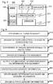
- Fig. 6shows a schematic flow chart illustrating a process according to an example embodiment.
- step 610the eye 112 moves i.e. turns in its socket so that the bulging cornea moves with respect to the sensor 102.
- the sensor 102detects 620 a change in the position of the cornea and produces respective or respectively changed analogue signals to the driver 104.
- the driver or an intervening analogue-to-digital converterconverts 630 the analogue signals into digital form.
- the driver 106determines 640 how the eye 112 has moved and outputs 650 corresponding eye tracking information.
- the driver 106 or another entity of the apparatus 100can also receive 660 other sensory information such as heartbeat sensor information, microphone signals and / or touch sensor information.
- the driver 106makes sensory determinations 670 such as determination of pulse of the user, surrounding noise (clapping of hands sensory determination information is output 680 for use of the controller 500, for instance.
- a technical effect of one or more of the example embodiments disclosed hereinis that the eyes of a user can be tracked with contactless arrangement. Another technical effect of one or more of the example embodiments disclosed herein is that the contactless arrangement can be portable. Another technical effect of one or more of the example embodiments disclosed herein is that further sensory determinations can be made in conjunction with eye tracking.
- Embodiments of the present inventionmay be implemented in software, hardware, application logic or a combination of software, hardware and application logic.
- the software, application logic and/or hardwaremay reside on a driver and/or on an external device communicatively connected with the driver.
- the application logic, software or an instruction setis maintained on any one of various conventional computer-readable media.
- a "computer-readable medium"may be any media or means that can contain, store, communicate, propagate or transport the instructions for use by or in connection with an instruction execution system, apparatus, or device, such as a computer, with an example of a computer described and depicted in Fig. 5 .
- a computer-readable mediummay comprise a computer-readable storage medium that may be any media or means that can contain or store the instructions for use by or in connection with an instruction execution system, apparatus, or device, such as a computer.
- the different functions discussed hereinmay be performed in a different order and/or concurrently with each other. Furthermore, if desired, one or more of the above-described functions may be optional or may be combined.
Landscapes
- Engineering & Computer Science (AREA)
- Physics & Mathematics (AREA)
- Health & Medical Sciences (AREA)
- General Engineering & Computer Science (AREA)
- Theoretical Computer Science (AREA)
- Life Sciences & Earth Sciences (AREA)
- Human Computer Interaction (AREA)
- General Physics & Mathematics (AREA)
- General Health & Medical Sciences (AREA)
- Ophthalmology & Optometry (AREA)
- Medical Informatics (AREA)
- Public Health (AREA)
- Biomedical Technology (AREA)
- Molecular Biology (AREA)
- Surgery (AREA)
- Animal Behavior & Ethology (AREA)
- Biophysics (AREA)
- Heart & Thoracic Surgery (AREA)
- Veterinary Medicine (AREA)
- Acoustics & Sound (AREA)
- Otolaryngology (AREA)
- Optics & Photonics (AREA)
- User Interface Of Digital Computer (AREA)
- Eye Examination Apparatus (AREA)
Description
- The present application generally relates to eye tracking. In particular, though not exclusively, the present application relates to contactless eye tracking.
- Eyes of human beings move for various reasons. There are voluntary movements and involuntary movements. The tracking of the eye movements has various applications such as detecting drowsiness of drivers.
- Eye tracking devices are often divided into contacting and contactless devices. There are devices that look into the eye using a camera system and deduce eye movements from optical signals. There are also devices in which a sensor is attached to the eye like a contact lens, or in which electric changes about the eye are measured with pads connected to the skin around the eye.
WO-A-91/13584 - Various aspects of examples of the invention are set out in the claims.
- According to a first example aspect of the present invention, there is provided an apparatus comprising:
- transparent capacitive sensor;
- a body configured to support the transparent capacitive sensor in front of an eye of a user; and
- a driver configured to receive signals from the sensor and to determine eye movements based on the received signals,
- the sensor being configured to detect movement of the eye based on the electrostatic effect caused by the bulge of the cornea.
- The apparatus may be wearable by the user. The apparatus may be wearable like eyeglasses.
- The sensor may be made of transparent material.
- The sensor may be formed in a sheet of transparent material. The sheet may also form the body.
- The body may be supported by the nose of the user and /or by one or two ears of the user.
- The sensor may be integrated with a lens of eyeglasses. Alternatively, the sensor may be attached to a lens of eyeglasses or to a frame of eyeglasses so that the sensor resides between the eye of the user and a lens of the eyeglasses, when the eyeglasses are worn by the user.
- The sensor may be attached to a display of video glasses.
- The sensor may be comprise transparent conductive material selected from a group consisting of: Indium Tin Oxide; Carbon nanotube based conductive coatings; films of graphene; thin metal films; inherently conductive polymers (ICPs); aluminum zinc oxide (AZO), gallium zinc oxide (GZO) or indium zinc oxide (IZO).
- The sensor may be covered by a protective coating.
- The sensor may comprise two layers of transparent conductive material sandwiching a layer of non-conductive material.
- The sensor may be attached to a lens of eyeglasses by optical adhesive.
- The apparatus may comprise a flexible printed circuit (FPC) configured to operatively connect the sensor to the driver.
- The apparatus may comprise a printed wiring board (PWB) configured to operatively connect the sensor to the driver.
- The apparatus may comprise a printed wiring board (PWB) configured to operatively connect the sensor to the driver.
- The apparatus may comprise an analog-to-digital converter configured to convert analog signals produced by the sensor to digital signals.
- The driver may comprise the analog-to-digital converter.
- The flexible printed circuit may comprise the driver. Alternatively, the printed wiring board may comprise the driver.
- The flexible printed circuit may comprise the analog-to-digital converter. Alternatively, the printed wiring board may comprise the analog-to-digital converter.
- The apparatus may comprise a touch controller. The touch controller may be configured to detect touching of the user at one or more touch sensitive areas in the body and/or on the driver.
- The apparatus may further comprise a heartbeat detector. The heartbeat detector may be integrated with or attached to the body. The heartbeat detector may be arranged behind an ear of the user when the apparatus is worn by the user.
- The body may be formed of eyeglass frames.
- The body may be configured to support the transparent capacitive sensor in front of the eye of a user at a proximate distance. The proximate distance may be such that the eyelash of the user does not reach to transparent materials in front of the eye. The proximate distance may be such that the eyebrow of the user does not reach to transparent materials in the visible field of the eye. The proximate distance may correspond to the distance of normal eyeglass lenses from eyes.
- The apparatus may comprise two of the sensors. The apparatus may be configured support one of the sensors in front of each of two eyes of the user.
- The apparatus may comprise a wired connection interface for connecting with an external device. The apparatus may be configured to provide the external device with eye tracking signals corresponding to the detected eye movements.
- The apparatus may be configured to provide the external device with eye tracking signals corresponding to other sensory data collected by the apparatus, such as heartbeat information or touch information.
- The wired connection interface may comply with a standard. The standard may be selected from a group consisting of Inter-Integrated Circuit (I2C) protocol, Serial Peripheral Interface (SPI), Universal serial bus (USB) and IEEE-1394.
- The apparatus may be configured to receive operating power from the external device.
- The apparatus may comprise a wireless connection interface for connecting with an external device. The wireless connection interface may comply with a standard. The standard may be selected from a group consisting of: low power Bluetooth, IEEE 802.11 (wireless LAN), ultra-wide band (UWB) radio link, and Infrared Data Association (IrDA) link.
- According to a second example aspect of the present invention, there is provided a method comprising:
- supporting a transparent capacitive sensor in front of an eye of a user;
- sensing movement of the eye of the user by the transparent capacitive sensor and producing corresponding signals; and
- determining eye movements based on the produced signals,
- receiving signals from a transparent capacitive sensor located in front of an eye of a user; and
- determining movement of the eye based on the received signals.
- According to fourth example aspect of the present invention, there is provided a computer program, comprising:
- code for receiving signals from a transparent capacitive sensor located in front of an eye of a user; and
- code for determining movement of the eye based on the received signal
- when the computer program is run on a processor.
- According to a fifth example aspect of the present invention, there is provided an apparatus comprising:
- means for transparent capacitive sensing;
- body means for supporting the means for transparent capacitive sensing in front of an eye of a user; and
- driver means for receiving signals from the transparent capacitive sensing means and for determining eye movements based on the received signals.
- Any foregoing memory medium may comprise a digital data storage such as a data disc or diskette, optical storage, magnetic storage, holographic storage, opto-magnetic storage, phase-change memory, resistive random access memory, magnetic random access memory, solid-electrolyte memory, ferroelectric random access memory, organic memory or polymer memory. The memory medium may be formed into a device without other substantial functions than storing memory or it may be formed as part of a device with other functions, including but not limited to a memory of a computer, a chip set, and a sub assembly of an electronic device.
- Different non-binding example aspects and embodiments of the present invention have been illustrated in the foregoing. The above embodiments are used merely to explain selected aspects or steps that may be utilized in implementations of the present invention. Some embodiments may be presented only with reference to certain example aspects of the invention. It should be appreciated that corresponding embodiments may apply to other example aspects as well.
- For a more complete understanding of example embodiments of the present invention, reference is now made to the following descriptions taken in connection with the accompanying drawings in which:
Figs. 1 and 2 show a schematic drawing of a head-worn apparatus, when seen from front and side, respectively;Fig. 3 is a schematic drawing of layers of a transparent capacitive sensor according to an example embodiment;Fig. 4 is a schematic drawing of layers of a transparent capacitive sensor according to an example embodiment;Fig. 5 shows equipment suited for illustration of a controller according to an example an example embodiment of; andFig. 6 shows a schematic flow chart illustrating a process according to an example embodiment.- An example embodiment of the present invention and its potential advantages are understood by referring to
Figs. 1 through 6 of the drawings. Figs. 1 and 2 show a schematic drawing of a head-worn apparatus 100, when seen from front and side, respectively. Theapparatus 100 comprises atransparent capacitive sensor 102 supported by abody 101 or frame in front of aneye 112 of auser 110. Theapparatus 100 further comprises adriver 106 configured to receive signals from thesensor 102 and to determine eye movements based on the received signals.- It is known that the human eye has a bulge at the cornea. The
sensor 102 can detect movement of theeye 112 based on the electrostatic effect caused by the bulge of the cornea of theeye 112. - The apparatus may be wearable by the user. The apparatus may be wearable like eyeglasses.
- The
sensor 102 ofFig. 2 is made of transparent conductive material so that theuser 110 can see through thesensor 102. For instance, the sensor can be formed of a sheet of transparent conductive material. In an example embodiment, unlike inFigs. 1 and 2 , the sheet also forms thebody 101. Such a sheet can be attached to the head e.g. by adhesive material such as glue or tape or by forming it suitably to conform to the shapes of the head so that the sheet attaches to the head sufficiently to remain in place at least when theuser 110 remains still. - In an example embodiment and in
Fig. 2 , thebody 101 is supported by thenose 114 of the user and / or by one or twoears 116 of the user. - In an example embodiment and in
Fig. 2 , the sensor is attached to a lens or to the frame of eyeglasses so that thesensor 102 resides between the eye of the user and a lens of the eyeglasses, when the eyeglasses are worn by the user. In an alternate example embodiment, the sensor is integrated with a lens of eyeglasses. - In an example embodiment and in
Fig. 3 , thesensor 102 is adhesively attached to a lens of eyeglasses on the side towards the eye. In such a case, the user watches through a series of adjacent optically transparent layers of: protective coatings orlayers 310 of thickness d2 (e.g. 0.05 mm), a first conductivetransparent layer 320, an insulatinglayer 330 such as a film of polyethylene terephthalate (PET), glass or isotropic plastics material and a second conductivetransparent layer 340. The first and second transparentconductive layers layer 330 together form asensor 102 of an example embodiment. The thickness of such asensor 102 is marked inFig. 3 as d1 that is, for instance, 0.1 mm to 0.125 mm thick. Further,Fig. 3 shows an opticaladhesive layer 350 of, for instance, optically clear adhesive (OCA) of thickness d3 that is, for example, 0.05 mm to 0.1 mm thick. Behind theadhesive layer 350,Fig. 3 shows the lens of theeyeglasses 104. It is understood that through this description the presented examples of thicknesses and compositions of various layers merely represent particular example embodiments. - In an example embodiment, the transparent conductive material is selected from a group consisting of: Indium Tin Oxide; Carbon nanotube based conductive coatings; films of graphene; thin metal films; inherently conductive polymers (ICPs); aluminum zinc oxide (AZO), gallium zinc oxide (GZO) or indium zinc oxide (IZO).
- The
apparatus 100 comprises, in an example embodiment, a flexible printed circuit (FPC) configured to operatively connect thesensor 102 to thedriver 106. The flexible printed circuit can be used to enable hinging of theframe 101 as with normal eyeglasses. In an alternative embodiment, theapparatus 100 comprises a printed wiring board (PWB) configured to operatively connect thesensor 102 to thedriver 104. In such an embodiment, theframe 101 is not hinged or thedriver 104 can be so located that theframe 101 can be normally hinged. For instance, thedriver 104 can reside at a lower or upper portion of a frame surrounding thelens 104 or in the middle part of theframe 101 bridging the left and right lenses over thenose 114 of theuser 110. - The
apparatus 100 ofFigs. 1 and 2 comprises an analog-to-digital converter configured to convert analog signals produced by thesensor 102 to digital signals. The analog-to-digital converter is embodied in an example embodiment in thedriver 106. Alternatively, in other example embodiments, the analog-to-digital converter resides on the flexible printed circuit may comprise the driver or on the printed wiring board. The driver can also be either separated or combined with the flexible printed circuit or with the printed wiring board. - In an example embodiment, the
apparatus 100 further comprises a touch controller for detecting touching of the user at one or more touch sensitive areas of theapparatus 100. The touch sensitive areas are provided in the body and/or on the driver. Thus, the user can be allowed to provide commands or information by touching one or more parts of theapparatus 100. In an example embodiment, the commands in question can be restricted to merely one command such as power on or power off. In other example embodiments, the commands may relate to controls of an application running in theapparatus 100 or at an external device. - In an example embodiment, the
apparatus 100 further comprises aheartbeat detector 108. In an example embodiment and inFig. 2 , the heartbeat detector is integrated with or attached to the body. The heartbeat detector is shown inFig. 2 arranged behind an ear of the user when the apparatus is worn by the user. - In an example embodiment and in
Fig. 2 , thebody 101 is configured to support thetransparent capacitive sensor 102 in front of theeye 112 of theuser 110 at a proximate distance. The proximate distance is, for instance, such that the eyelash of the user does not reach to transparent materials in front of the eye. The proximate distance can also be that long that the eyebrow of the user does not reach to transparent materials in the visible field of the eye. In an example embodiment and inFig. 2 , the proximate distance corresponds to the distance of normal eyeglass lenses from theeyes 112 of theuser 110. - In an example embodiment and in
Figs. 1 and 2 , theapparatus 100 comprises two of thesensors 102. Theapparatus 100 is then configured support one of the sensors in front of each of two eyes of the user. In an alternative two-eye implementation, the apparatus has one extended sensor that extends over both eyes of the user. - For communicating with external devices, the apparatus has a connection interface in some example embodiments. Then, the apparatus can provide the external device with eye tracking signals corresponding to the detected eye movements. The apparatus can also be configured to provide the external device with eye tracking signals corresponding to other sensory data collected by the apparatus, such as heartbeat information or touch information.
- In an example embodiment, the communication interface comprises a wired connection interface. The wired connection interface is, for example, compliant with a standard, such as Inter-Integrated Circuit (I2C) protocol, Serial Peripheral Interface (SPI), Universal serial bus (USB) or IEEE-1394.
- In an example embodiment, the apparatus is configured to receive operating power from the external device. The power can be received through the wired communication interface. For instance, USB and IEEE-1394 readily provide for power transfer simultaneously with data transfer.
- In an example embodiment, the communication interface comprises a wireless connection interface. The wireless connection interface is, for instance, compliant with a standard such as low power Bluetooth, IEEE 802.11 (wireless LAN), ultra-wide band (UWB) radio link or Infrared Data Association (IrDA) link.
- The
apparatus 100 or an external device communicatively connectable with the apparatus (wirelessly or with wires) comprises in an example embodiment acontroller 500 configured to use eye tracking information produced by theapparatus 100 for controlling an application, function of a controllable entity or a service accordingly.Fig. 5 shows an example embodiment of equipment suited for illustration of the controller.Fig. 5 can also be suited for illustration of the driver according to some example embodiments. - The
device 500 comprises acommunication interface 520, aprocessor 510 coupled to thecommunication interface module 520, and amemory 540 coupled to theprocessor 510. Thememory 540 comprises a work memory and a non-volatile memory such as a read-only memory, flash memory, optical or magnetic memory. In thememory 540, typically at least initially in the non-volatile memory, there is storedsoftware 550 operable to be loaded into and executed by theprocessor 510. Thesoftware 550 may comprise one or more software modules and can be in the form of a computer program product that is software stored in a memory medium. Thedevice 500 further comprises a 102 and adriver 570 each coupled to the processor (when exemplifying theapparatus 100, but not necessarily when exemplifying an external device). - It shall be understood that any coupling in this document refers to functional or operational coupling; there may be intervening components or circuitries in between coupled elements.
- The
communication interface module 520 is configured to provide local communications over one or more local links. The links may be wired and/or wireless links. Thecommunication interface 520 may further or alternatively implement telecommunication links suited for establishing links with other users or for data transfer (e.g. using the Internet). Such telecommunication links may be links using any of: wireless local area network links, Bluetooth, ultra-wideband, cellular or satellite communication links. Thecommunication interface 520 may be integrated into thedevice 500 or into an adapter, card or the like that may be inserted into a suitable slot or port of thedevice 500. WhileFig. 5 shows onecommunication interface 520, the device may comprise a plurality of communication interfaces 520. - The
processor 510 is, for instance, a central processing unit (CPU), a microprocessor, a digital signal processor (DSP), a graphics processing unit, an application specific integrated circuit (ASIC), a field programmable gate array, a microcontroller or a combination of such elements.Figure 5 shows oneprocessor 510, but thedevice 500 may comprise a plurality of processors. - As mentioned in the foregoing, the
memory 540 may comprise volatile and a non-volatile memory, such as a read-only memory (ROM), a programmable read-only memory (PROM), erasable programmable read-only memory (EPROM), a random-access memory (RAM), a flash memory, a data disk, an optical storage, a magnetic storage, a smart card, or the like. In some example embodiments, only volatile or non-volatile memory is present in thedevice 500. Moreover, in some example embodiments, the device comprises a plurality of memories. In some example embodiments, various elements are integrated. For instance, thememory 540 can be constructed as a part of thedevice 500 or inserted into a slot, port, or the like. Further still, thememory 540 may serve the sole purpose of storing data, or it may be constructed as a part of an apparatus serving other purposes, such as processing data. Similar options are thinkable also for various other elements. - A skilled person appreciates that in addition to the elements shown in
Figure 5 , thedevice 500 may comprise other elements, such as microphones, displays, as well as additional circuitry such as further input/output (I/O) circuitries, memory chips, application-specific integrated circuits (ASIC), processing circuitry for specific purposes such as source coding/decoding circuitry, channel coding/decoding circuitry, ciphering/deciphering circuitry, and the like. Additionally, thedevice 500 may comprise a disposable or rechargeable battery (not shown) for powering the device when external power if external power supply is not available. Fig. 6 shows a schematic flow chart illustrating a process according to an example embodiment.- In
step 610, theeye 112 moves i.e. turns in its socket so that the bulging cornea moves with respect to thesensor 102. In response, thesensor 102 detects 620 a change in the position of the cornea and produces respective or respectively changed analogue signals to thedriver 104. The driver or an intervening analogue-to-digital converter converts 630 the analogue signals into digital form. Armed with the digital signals, thedriver 106 determines 640 how theeye 112 has moved andoutputs 650 corresponding eye tracking information. Thedriver 106 or another entity of theapparatus 100 can also receive 660 other sensory information such as heartbeat sensor information, microphone signals and / or touch sensor information. In response, thedriver 106 makessensory determinations 670 such as determination of pulse of the user, surrounding noise (clapping of hands sensory determination information isoutput 680 for use of thecontroller 500, for instance. - The eye tracking information is used according to different example embodiments various uses such as:
- 1. Activity Recognition
- 2. Advertising studies
- 3. Cognitive Studies
- 4. Communication systems for disabled
- 5. Computer usability studies
- 6. Enriched image and video communications where eye movements indicate feelings or reactions
- 7. Fatigue Detection
- 8. Geriatric Research
- 9. In-vehicle Research
- 10. Medical Research
- 11. Training Simulators
- 12. Vehicle Simulators
- 13. Virtual Reality
- Without in any way limiting the scope, interpretation, or application of the claims appearing below, a technical effect of one or more of the example embodiments disclosed herein is that the eyes of a user can be tracked with contactless arrangement. Another technical effect of one or more of the example embodiments disclosed herein is that the contactless arrangement can be portable. Another technical effect of one or more of the example embodiments disclosed herein is that further sensory determinations can be made in conjunction with eye tracking.
- Embodiments of the present invention may be implemented in software, hardware, application logic or a combination of software, hardware and application logic. The software, application logic and/or hardware may reside on a driver and/or on an external device communicatively connected with the driver. In an example embodiment, the application logic, software or an instruction set is maintained on any one of various conventional computer-readable media. In the context of this document, a "computer-readable medium" may be any media or means that can contain, store, communicate, propagate or transport the instructions for use by or in connection with an instruction execution system, apparatus, or device, such as a computer, with an example of a computer described and depicted in
Fig. 5 . A computer-readable medium may comprise a computer-readable storage medium that may be any media or means that can contain or store the instructions for use by or in connection with an instruction execution system, apparatus, or device, such as a computer. - If desired, the different functions discussed herein may be performed in a different order and/or concurrently with each other. Furthermore, if desired, one or more of the above-described functions may be optional or may be combined.
- Although various aspects of the invention are set out in the independent claims, other aspects of the invention comprise other combinations of features from the described embodiments and/or the dependent claims with the features of the independent claims, and not solely the combinations explicitly set out in the claims.
- It is also noted herein that while the above describes example embodiments of the invention, these descriptions should not be viewed in a limiting sense. Rather, there are several variations and modifications which may be made without departing from the scope of the present invention as defined in the appended claims.
Claims (15)
- An apparatus, comprising:a capacitive sensor (102);a body (101) configured to support the capacitive sensor; anda driver (106) configured to receive signals from the capacitive sensor and to determine eye movements of a user based on the received signals;wherein the sensor is configured to detect movement of the eye;characterized in thatthe capacitive sensor is a transparent capacitive sensor;the body is configured to support the sensor in front of an eye of a user; andthe sensor is configured to detect movement of the eye based on electrostatic effect caused by a bulge of eye cornea.
- The apparatus of claim 1, wherein the apparatus is wearable by the user.
- The apparatus of any of the preceding claims, wherein the apparatus is wearable as eyeglasses.
- The apparatus of any of the preceding claims, wherein the apparatus is wearable as video glasses.
- The apparatus of any of the preceding claims, wherein the sensor comprises two layers of transparent conductive material sandwiching a layer of non-conductive material.
- The apparatus of any of the preceding claims, configured to track the eyes of a user with contactless arrangement.
- The apparatus of any of the preceding claims, wherein the sensor is integrated with a lens of eyeglasses.
- The apparatus of any of claims 1 to 6, wherein the sensor is attached to a lens of eyeglasses or to a frame of eyeglasses so that the sensor resides between the eye of the user and a lens of the eyeglasses, when the eyeglasses are worn by the user.
- The apparatus of any of the preceding claims, further comprising a touch controller that is configured to detect touching of the user at one or more touch sensitive areas in the body and/or on the driver.
- The apparatus of any of the preceding claims, further comprising a heartbeat detector.
- The apparatus of claim 10 wherein the heartbeat detector is integrated with or attached to the body.
- The apparatus of any of the preceding claims, further comprising a wireless connection interface for connecting with an external device.
- A method comprising:supporting a transparent capacitive sensor in front of an eye of a user;sensing movement of the eye of the user by the transparent capacitive sensor and producing corresponding signals; anddetermining eye movements based on the produced signals based on electrostatic effect caused by a bulge of eye cornea.
- The method of claim 13 comprising performing the method in an apparatus that is wearable by the user.
- The method of claim 14, comprising tracking the eyes of a user with contactless arrangement.
Applications Claiming Priority (1)
| Application Number | Priority Date | Filing Date | Title |
|---|---|---|---|
| PCT/FI2012/050071WO2013110846A1 (en) | 2012-01-26 | 2012-01-26 | Capacitive eye tracking sensor |
Publications (3)
| Publication Number | Publication Date |
|---|---|
| EP2806782A1 EP2806782A1 (en) | 2014-12-03 |
| EP2806782A4 EP2806782A4 (en) | 2015-09-23 |
| EP2806782B1true EP2806782B1 (en) | 2019-08-14 |
Family
ID=48872916
Family Applications (1)
| Application Number | Title | Priority Date | Filing Date |
|---|---|---|---|
| EP12866908.2AActiveEP2806782B1 (en) | 2012-01-26 | 2012-01-26 | Capacitive eye tracking sensor |
Country Status (4)
| Country | Link |
|---|---|
| US (1) | US9414746B2 (en) |
| EP (1) | EP2806782B1 (en) |
| CN (1) | CN104066371B (en) |
| WO (1) | WO2013110846A1 (en) |
Families Citing this family (112)
| Publication number | Priority date | Publication date | Assignee | Title |
|---|---|---|---|---|
| US9158116B1 (en) | 2014-04-25 | 2015-10-13 | Osterhout Group, Inc. | Temple and ear horn assembly for headworn computer |
| US9298007B2 (en) | 2014-01-21 | 2016-03-29 | Osterhout Group, Inc. | Eye imaging in head worn computing |
| US9965681B2 (en) | 2008-12-16 | 2018-05-08 | Osterhout Group, Inc. | Eye imaging in head worn computing |
| US9229233B2 (en) | 2014-02-11 | 2016-01-05 | Osterhout Group, Inc. | Micro Doppler presentations in head worn computing |
| US20150205111A1 (en) | 2014-01-21 | 2015-07-23 | Osterhout Group, Inc. | Optical configurations for head worn computing |
| US9366867B2 (en) | 2014-07-08 | 2016-06-14 | Osterhout Group, Inc. | Optical systems for see-through displays |
| US9715112B2 (en) | 2014-01-21 | 2017-07-25 | Osterhout Group, Inc. | Suppression of stray light in head worn computing |
| US9400390B2 (en) | 2014-01-24 | 2016-07-26 | Osterhout Group, Inc. | Peripheral lighting for head worn computing |
| US9952664B2 (en) | 2014-01-21 | 2018-04-24 | Osterhout Group, Inc. | Eye imaging in head worn computing |
| US20150277120A1 (en) | 2014-01-21 | 2015-10-01 | Osterhout Group, Inc. | Optical configurations for head worn computing |
| US9086881B2 (en)* | 2012-06-29 | 2015-07-21 | Intel Corporation | Mechanism for facilitating write tracking for following data eye movements across changing thermal conditions in memory systems |
| WO2015021624A1 (en)* | 2013-08-14 | 2015-02-19 | 宇龙计算机通信科技(深圳)有限公司 | Wearable device and data transmission method |
| US11227294B2 (en) | 2014-04-03 | 2022-01-18 | Mentor Acquisition One, Llc | Sight information collection in head worn computing |
| US11103122B2 (en) | 2014-07-15 | 2021-08-31 | Mentor Acquisition One, Llc | Content presentation in head worn computing |
| US10649220B2 (en) | 2014-06-09 | 2020-05-12 | Mentor Acquisition One, Llc | Content presentation in head worn computing |
| US9529195B2 (en) | 2014-01-21 | 2016-12-27 | Osterhout Group, Inc. | See-through computer display systems |
| US10254856B2 (en) | 2014-01-17 | 2019-04-09 | Osterhout Group, Inc. | External user interface for head worn computing |
| US9939934B2 (en) | 2014-01-17 | 2018-04-10 | Osterhout Group, Inc. | External user interface for head worn computing |
| US9594246B2 (en) | 2014-01-21 | 2017-03-14 | Osterhout Group, Inc. | See-through computer display systems |
| US20160019715A1 (en) | 2014-07-15 | 2016-01-21 | Osterhout Group, Inc. | Content presentation in head worn computing |
| US9810906B2 (en) | 2014-06-17 | 2017-11-07 | Osterhout Group, Inc. | External user interface for head worn computing |
| US20150277118A1 (en) | 2014-03-28 | 2015-10-01 | Osterhout Group, Inc. | Sensor dependent content position in head worn computing |
| US9671613B2 (en) | 2014-09-26 | 2017-06-06 | Osterhout Group, Inc. | See-through computer display systems |
| US9829707B2 (en) | 2014-08-12 | 2017-11-28 | Osterhout Group, Inc. | Measuring content brightness in head worn computing |
| US9746686B2 (en) | 2014-05-19 | 2017-08-29 | Osterhout Group, Inc. | Content position calibration in head worn computing |
| US10191279B2 (en) | 2014-03-17 | 2019-01-29 | Osterhout Group, Inc. | Eye imaging in head worn computing |
| US9841599B2 (en) | 2014-06-05 | 2017-12-12 | Osterhout Group, Inc. | Optical configurations for head-worn see-through displays |
| US20150228119A1 (en) | 2014-02-11 | 2015-08-13 | Osterhout Group, Inc. | Spatial location presentation in head worn computing |
| US9366868B2 (en) | 2014-09-26 | 2016-06-14 | Osterhout Group, Inc. | See-through computer display systems |
| US9448409B2 (en) | 2014-11-26 | 2016-09-20 | Osterhout Group, Inc. | See-through computer display systems |
| US9299194B2 (en) | 2014-02-14 | 2016-03-29 | Osterhout Group, Inc. | Secure sharing in head worn computing |
| US9575321B2 (en) | 2014-06-09 | 2017-02-21 | Osterhout Group, Inc. | Content presentation in head worn computing |
| US10684687B2 (en) | 2014-12-03 | 2020-06-16 | Mentor Acquisition One, Llc | See-through computer display systems |
| US9836122B2 (en) | 2014-01-21 | 2017-12-05 | Osterhout Group, Inc. | Eye glint imaging in see-through computer display systems |
| US9651784B2 (en) | 2014-01-21 | 2017-05-16 | Osterhout Group, Inc. | See-through computer display systems |
| US12093453B2 (en) | 2014-01-21 | 2024-09-17 | Mentor Acquisition One, Llc | Eye glint imaging in see-through computer display systems |
| US9310610B2 (en) | 2014-01-21 | 2016-04-12 | Osterhout Group, Inc. | See-through computer display systems |
| US11669163B2 (en) | 2014-01-21 | 2023-06-06 | Mentor Acquisition One, Llc | Eye glint imaging in see-through computer display systems |
| US9811152B2 (en) | 2014-01-21 | 2017-11-07 | Osterhout Group, Inc. | Eye imaging in head worn computing |
| US9615742B2 (en) | 2014-01-21 | 2017-04-11 | Osterhout Group, Inc. | Eye imaging in head worn computing |
| US12105281B2 (en) | 2014-01-21 | 2024-10-01 | Mentor Acquisition One, Llc | See-through computer display systems |
| US9753288B2 (en) | 2014-01-21 | 2017-09-05 | Osterhout Group, Inc. | See-through computer display systems |
| US9494800B2 (en) | 2014-01-21 | 2016-11-15 | Osterhout Group, Inc. | See-through computer display systems |
| US20150205135A1 (en) | 2014-01-21 | 2015-07-23 | Osterhout Group, Inc. | See-through computer display systems |
| US9651788B2 (en) | 2014-01-21 | 2017-05-16 | Osterhout Group, Inc. | See-through computer display systems |
| US11487110B2 (en) | 2014-01-21 | 2022-11-01 | Mentor Acquisition One, Llc | Eye imaging in head worn computing |
| US11737666B2 (en) | 2014-01-21 | 2023-08-29 | Mentor Acquisition One, Llc | Eye imaging in head worn computing |
| US9766463B2 (en) | 2014-01-21 | 2017-09-19 | Osterhout Group, Inc. | See-through computer display systems |
| US9740280B2 (en) | 2014-01-21 | 2017-08-22 | Osterhout Group, Inc. | Eye imaging in head worn computing |
| US11892644B2 (en) | 2014-01-21 | 2024-02-06 | Mentor Acquisition One, Llc | See-through computer display systems |
| US9846308B2 (en) | 2014-01-24 | 2017-12-19 | Osterhout Group, Inc. | Haptic systems for head-worn computers |
| US12112089B2 (en) | 2014-02-11 | 2024-10-08 | Mentor Acquisition One, Llc | Spatial location presentation in head worn computing |
| US9852545B2 (en) | 2014-02-11 | 2017-12-26 | Osterhout Group, Inc. | Spatial location presentation in head worn computing |
| US9401540B2 (en) | 2014-02-11 | 2016-07-26 | Osterhout Group, Inc. | Spatial location presentation in head worn computing |
| US20160187651A1 (en) | 2014-03-28 | 2016-06-30 | Osterhout Group, Inc. | Safety for a vehicle operator with an hmd |
| DE102014105374B4 (en)* | 2014-04-15 | 2017-02-09 | Deutsches Zentrum für Luft- und Raumfahrt e.V. | Driver assistance system |
| US10853589B2 (en) | 2014-04-25 | 2020-12-01 | Mentor Acquisition One, Llc | Language translation with head-worn computing |
| US9651787B2 (en) | 2014-04-25 | 2017-05-16 | Osterhout Group, Inc. | Speaker assembly for headworn computer |
| US9423842B2 (en) | 2014-09-18 | 2016-08-23 | Osterhout Group, Inc. | Thermal management for head-worn computer |
| US20150309534A1 (en) | 2014-04-25 | 2015-10-29 | Osterhout Group, Inc. | Ear horn assembly for headworn computer |
| US9672210B2 (en) | 2014-04-25 | 2017-06-06 | Osterhout Group, Inc. | Language translation with head-worn computing |
| US20160137312A1 (en) | 2014-05-06 | 2016-05-19 | Osterhout Group, Inc. | Unmanned aerial vehicle launch system |
| US10663740B2 (en) | 2014-06-09 | 2020-05-26 | Mentor Acquisition One, Llc | Content presentation in head worn computing |
| US9684172B2 (en) | 2014-12-03 | 2017-06-20 | Osterhout Group, Inc. | Head worn computer display systems |
| USD743963S1 (en) | 2014-12-22 | 2015-11-24 | Osterhout Group, Inc. | Air mouse |
| USD751552S1 (en) | 2014-12-31 | 2016-03-15 | Osterhout Group, Inc. | Computer glasses |
| USD753114S1 (en) | 2015-01-05 | 2016-04-05 | Osterhout Group, Inc. | Air mouse |
| US20160239985A1 (en) | 2015-02-17 | 2016-08-18 | Osterhout Group, Inc. | See-through computer display systems |
| US10878775B2 (en) | 2015-02-17 | 2020-12-29 | Mentor Acquisition One, Llc | See-through computer display systems |
| US9888843B2 (en) | 2015-06-03 | 2018-02-13 | Microsoft Technology Licensing, Llc | Capacitive sensors for determining eye gaze direction |
| US10139966B2 (en) | 2015-07-22 | 2018-11-27 | Osterhout Group, Inc. | External user interface for head worn computing |
| CN105260017A (en)* | 2015-09-28 | 2016-01-20 | 南京民办致远外国语小学 | Glasses mouse and working method therefor |
| US10444972B2 (en) | 2015-11-28 | 2019-10-15 | International Business Machines Corporation | Assisting a user with efficient navigation between a selection of entries with elements of interest to the user within a stream of entries |
| WO2017115010A1 (en)* | 2015-12-29 | 2017-07-06 | Teknologian Tutkimuskeskus Vtt Oy | Acoustic transducing apparatus and method |
| US10850116B2 (en) | 2016-12-30 | 2020-12-01 | Mentor Acquisition One, Llc | Head-worn therapy device |
| US10591728B2 (en) | 2016-03-02 | 2020-03-17 | Mentor Acquisition One, Llc | Optical systems for head-worn computers |
| US10667981B2 (en) | 2016-02-29 | 2020-06-02 | Mentor Acquisition One, Llc | Reading assistance system for visually impaired |
| US9826299B1 (en) | 2016-08-22 | 2017-11-21 | Osterhout Group, Inc. | Speaker systems for head-worn computer systems |
| US9880441B1 (en) | 2016-09-08 | 2018-01-30 | Osterhout Group, Inc. | Electrochromic systems for head-worn computer systems |
| US10824253B2 (en) | 2016-05-09 | 2020-11-03 | Mentor Acquisition One, Llc | User interface systems for head-worn computers |
| US9910284B1 (en) | 2016-09-08 | 2018-03-06 | Osterhout Group, Inc. | Optical systems for head-worn computers |
| US10684478B2 (en) | 2016-05-09 | 2020-06-16 | Mentor Acquisition One, Llc | User interface systems for head-worn computers |
| US10466491B2 (en) | 2016-06-01 | 2019-11-05 | Mentor Acquisition One, Llc | Modular systems for head-worn computers |
| US10690936B2 (en) | 2016-08-29 | 2020-06-23 | Mentor Acquisition One, Llc | Adjustable nose bridge assembly for headworn computer |
| EP3919969A1 (en)* | 2016-09-22 | 2021-12-08 | Essilor International | Health monitoring device and wearing detection module for spectacles frame |
| USD840395S1 (en) | 2016-10-17 | 2019-02-12 | Osterhout Group, Inc. | Head-worn computer |
| WO2018098436A1 (en) | 2016-11-28 | 2018-05-31 | Spy Eye, Llc | Unobtrusive eye mounted display |
| EP3554832B1 (en) | 2016-12-16 | 2021-06-16 | 3M Innovative Properties Company | Infrared-reflecting optically transparent assembly and method of making the same |
| USD864959S1 (en) | 2017-01-04 | 2019-10-29 | Mentor Acquisition One, Llc | Computer glasses |
| US11244315B2 (en) | 2017-03-21 | 2022-02-08 | Intelligent Technologies International, Inc. | Authentication system for controlling access and use based on heartbeat shape |
| US10162413B2 (en)* | 2017-03-28 | 2018-12-25 | Synaptics Incorporated | Non-contact eye gaze tracking |
| US10578869B2 (en) | 2017-07-24 | 2020-03-03 | Mentor Acquisition One, Llc | See-through computer display systems with adjustable zoom cameras |
| US10422995B2 (en) | 2017-07-24 | 2019-09-24 | Mentor Acquisition One, Llc | See-through computer display systems with stray light management |
| US11409105B2 (en) | 2017-07-24 | 2022-08-09 | Mentor Acquisition One, Llc | See-through computer display systems |
| CN107392156B (en)* | 2017-07-25 | 2020-08-25 | 北京七鑫易维信息技术有限公司 | Sight estimation method and device |
| US10969584B2 (en) | 2017-08-04 | 2021-04-06 | Mentor Acquisition One, Llc | Image expansion optic for head-worn computer |
| CN107506030B (en)* | 2017-08-16 | 2021-03-30 | 陈乾 | Visual control instrument |
| US10673414B2 (en) | 2018-02-05 | 2020-06-02 | Tectus Corporation | Adaptive tuning of a contact lens |
| US10505394B2 (en) | 2018-04-21 | 2019-12-10 | Tectus Corporation | Power generation necklaces that mitigate energy absorption in the human body |
| US10895762B2 (en) | 2018-04-30 | 2021-01-19 | Tectus Corporation | Multi-coil field generation in an electronic contact lens system |
| US10838239B2 (en) | 2018-04-30 | 2020-11-17 | Tectus Corporation | Multi-coil field generation in an electronic contact lens system |
| TWI637289B (en)* | 2018-05-18 | 2018-10-01 | 緯創資通股份有限公司 | Eye tracking-based display control system |
| US10790700B2 (en) | 2018-05-18 | 2020-09-29 | Tectus Corporation | Power generation necklaces with field shaping systems |
| CN112218753A (en)* | 2018-06-04 | 2021-01-12 | 3M创新有限公司 | Thermoformed wear-resistant multilayer optical film and method of making same |
| US11137622B2 (en) | 2018-07-15 | 2021-10-05 | Tectus Corporation | Eye-mounted displays including embedded conductive coils |
| US10529107B1 (en) | 2018-09-11 | 2020-01-07 | Tectus Corporation | Projector alignment in a contact lens |
| US10827922B2 (en)* | 2018-10-22 | 2020-11-10 | Zongqi Hu | Apparatus and method for objective visual acuity measurement using dynamic velocity threshold filter in optokinetic response processing |
| US10838232B2 (en) | 2018-11-26 | 2020-11-17 | Tectus Corporation | Eye-mounted displays including embedded solenoids |
| US10644543B1 (en) | 2018-12-20 | 2020-05-05 | Tectus Corporation | Eye-mounted display system including a head wearable object |
| US10944290B2 (en) | 2019-08-02 | 2021-03-09 | Tectus Corporation | Headgear providing inductive coupling to a contact lens |
| EP3791775B1 (en) | 2019-09-16 | 2023-12-13 | Nokia Technologies Oy | Eyewear device |
| US12254129B2 (en)* | 2022-06-28 | 2025-03-18 | Microsoft Technology Licensing, Llc | Determining charge on a facial-tracking sensor |
Citations (1)
| Publication number | Priority date | Publication date | Assignee | Title |
|---|---|---|---|---|
| EP2226703A2 (en)* | 2009-03-02 | 2010-09-08 | Honeywell International Inc. | Wearable eye tracking system |
Family Cites Families (10)
| Publication number | Priority date | Publication date | Assignee | Title |
|---|---|---|---|---|
| IL93579A0 (en)* | 1990-02-28 | 1990-11-29 | Srd Medical Ltd | Apparatus for rapidly preparing to obtain biosignals |
| US5726916A (en) | 1996-06-27 | 1998-03-10 | The United States Of America As Represented By The Secretary Of The Army | Method and apparatus for determining ocular gaze point of regard and fixation duration |
| US7731360B2 (en)* | 2003-11-07 | 2010-06-08 | Neuro Kinetics | Portable video oculography system |
| US20060115130A1 (en) | 2004-11-29 | 2006-06-01 | Douglas Kozlay | Eyewear with biometrics to protect displayed data |
| US7967439B2 (en)* | 2005-05-19 | 2011-06-28 | The Johns Hopkins University | Wireless scleral search coil including systems for measuring eye movement and methods related thereto |
| JP2009291391A (en)* | 2008-06-05 | 2009-12-17 | Yaskawa Electric Corp | Pupil detection method, pupil position detector, and transmission type eye-direction detector |
| US7958789B2 (en)* | 2008-08-08 | 2011-06-14 | Tokai Rubber Industries, Ltd. | Capacitive sensor |
| WO2011100436A1 (en) | 2010-02-10 | 2011-08-18 | Lead Technology Capital Management, Llc | System and method of determining an area of concentrated focus and controlling an image displayed in response |
| SG186700A1 (en)* | 2010-06-01 | 2013-02-28 | Elenza Inc | Implantable ophthalmic device with an aspheric lens |
| US8184067B1 (en)* | 2011-07-20 | 2012-05-22 | Google Inc. | Nose bridge sensor |
- 2012
- 2012-01-26EPEP12866908.2Apatent/EP2806782B1/enactiveActive
- 2012-01-26CNCN201280067854.0Apatent/CN104066371B/enactiveActive
- 2012-01-26USUS14/365,176patent/US9414746B2/enactiveActive
- 2012-01-26WOPCT/FI2012/050071patent/WO2013110846A1/enactiveApplication Filing
Patent Citations (1)
| Publication number | Priority date | Publication date | Assignee | Title |
|---|---|---|---|---|
| EP2226703A2 (en)* | 2009-03-02 | 2010-09-08 | Honeywell International Inc. | Wearable eye tracking system |
Also Published As
| Publication number | Publication date |
|---|---|
| EP2806782A4 (en) | 2015-09-23 |
| CN104066371B (en) | 2016-09-28 |
| EP2806782A1 (en) | 2014-12-03 |
| US20150015847A1 (en) | 2015-01-15 |
| CN104066371A (en) | 2014-09-24 |
| US9414746B2 (en) | 2016-08-16 |
| WO2013110846A1 (en) | 2013-08-01 |
Similar Documents
| Publication | Publication Date | Title |
|---|---|---|
| EP2806782B1 (en) | Capacitive eye tracking sensor | |
| US11650624B2 (en) | Biometric sensor and device including the same | |
| US11287930B2 (en) | Capacitive sensors for determining eye gaze direction | |
| US20220236795A1 (en) | Systems and methods for signaling the onset of a user's intent to interact | |
| KR102230076B1 (en) | Head-mounted display apparatus | |
| US10535320B2 (en) | Head-mounted display apparatus | |
| CN105122201B (en) | Multiple point touching interaction on glasses | |
| US20160140887A1 (en) | Wearable electronic device | |
| KR200478490Y1 (en) | Head-mounted device | |
| US20160342206A1 (en) | Eye and head tracking device | |
| WO2022164881A1 (en) | Systems and methods for predicting an intent to interact | |
| KR20180130151A (en) | Electronic device comprising a module mounted on sunken area of layer | |
| US20130241927A1 (en) | Computer device in form of wearable glasses and user interface thereof | |
| KR101655792B1 (en) | Head-mounted display apparatus | |
| KR20170087635A (en) | Arrangement structure of sensor of electronic apparatus | |
| US12282596B2 (en) | Eye detection methods and devices | |
| KR20170087218A (en) | Display and electronic device including the same | |
| US20130285921A1 (en) | Systems and Methods for a Rollable Illumination Device | |
| EP3680702A1 (en) | Wearable display apparatus | |
| KR20170000187A (en) | Display device | |
| JP2015205114A (en) | Eyeglass-type electronic equipment | |
| WO2019169310A1 (en) | Apparatus, systems, and methods for sharing power between devices via wearers' bodies | |
| US20220413308A1 (en) | Wearable electronic device for providing virtual image | |
| KR20210107436A (en) | Electronic device including electrode in contact with body | |
| KR20170021671A (en) | Electronic device and controlling method thereof |
Legal Events
| Date | Code | Title | Description |
|---|---|---|---|
| PUAI | Public reference made under article 153(3) epc to a published international application that has entered the european phase | Free format text:ORIGINAL CODE: 0009012 | |
| 17P | Request for examination filed | Effective date:20140618 | |
| AK | Designated contracting states | Kind code of ref document:A1 Designated state(s):AL AT BE BG CH CY CZ DE DK EE ES FI FR GB GR HR HU IE IS IT LI LT LU LV MC MK MT NL NO PL PT RO RS SE SI SK SM TR | |
| DAX | Request for extension of the european patent (deleted) | ||
| RAP1 | Party data changed (applicant data changed or rights of an application transferred) | Owner name:NOKIA TECHNOLOGIES OY | |
| RA4 | Supplementary search report drawn up and despatched (corrected) | Effective date:20150821 | |
| RIC1 | Information provided on ipc code assigned before grant | Ipc:A61B 5/00 20060101ALI20150817BHEP Ipc:A61B 3/113 20060101AFI20150817BHEP Ipc:G02C 11/00 20060101ALI20150817BHEP Ipc:G06F 3/041 20060101ALI20150817BHEP Ipc:A61B 5/0496 20060101ALI20150817BHEP Ipc:G06F 3/01 20060101ALI20150817BHEP | |
| STAA | Information on the status of an ep patent application or granted ep patent | Free format text:STATUS: EXAMINATION IS IN PROGRESS | |
| 17Q | First examination report despatched | Effective date:20181004 | |
| GRAP | Despatch of communication of intention to grant a patent | Free format text:ORIGINAL CODE: EPIDOSNIGR1 | |
| STAA | Information on the status of an ep patent application or granted ep patent | Free format text:STATUS: GRANT OF PATENT IS INTENDED | |
| INTG | Intention to grant announced | Effective date:20190226 | |
| GRAJ | Information related to disapproval of communication of intention to grant by the applicant or resumption of examination proceedings by the epo deleted | Free format text:ORIGINAL CODE: EPIDOSDIGR1 | |
| STAA | Information on the status of an ep patent application or granted ep patent | Free format text:STATUS: EXAMINATION IS IN PROGRESS | |
| INTC | Intention to grant announced (deleted) | ||
| GRAR | Information related to intention to grant a patent recorded | Free format text:ORIGINAL CODE: EPIDOSNIGR71 | |
| GRAS | Grant fee paid | Free format text:ORIGINAL CODE: EPIDOSNIGR3 | |
| STAA | Information on the status of an ep patent application or granted ep patent | Free format text:STATUS: GRANT OF PATENT IS INTENDED | |
| GRAA | (expected) grant | Free format text:ORIGINAL CODE: 0009210 | |
| STAA | Information on the status of an ep patent application or granted ep patent | Free format text:STATUS: THE PATENT HAS BEEN GRANTED | |
| AK | Designated contracting states | Kind code of ref document:B1 Designated state(s):AL AT BE BG CH CY CZ DE DK EE ES FI FR GB GR HR HU IE IS IT LI LT LU LV MC MK MT NL NO PL PT RO RS SE SI SK SM TR | |
| INTG | Intention to grant announced | Effective date:20190705 | |
| REG | Reference to a national code | Ref country code:GB Ref legal event code:FG4D | |
| REG | Reference to a national code | Ref country code:CH Ref legal event code:EP Ref country code:AT Ref legal event code:REF Ref document number:1166035 Country of ref document:AT Kind code of ref document:T Effective date:20190815 | |
| RAP2 | Party data changed (patent owner data changed or rights of a patent transferred) | Owner name:NOKIA TECHNOLOGIES OY | |
| REG | Reference to a national code | Ref country code:IE Ref legal event code:FG4D | |
| REG | Reference to a national code | Ref country code:DE Ref legal event code:R096 Ref document number:602012063024 Country of ref document:DE | |
| REG | Reference to a national code | Ref country code:NL Ref legal event code:MP Effective date:20190814 | |
| REG | Reference to a national code | Ref country code:LT Ref legal event code:MG4D | |
| PG25 | Lapsed in a contracting state [announced via postgrant information from national office to epo] | Ref country code:NO Free format text:LAPSE BECAUSE OF FAILURE TO SUBMIT A TRANSLATION OF THE DESCRIPTION OR TO PAY THE FEE WITHIN THE PRESCRIBED TIME-LIMIT Effective date:20191114 Ref country code:PT Free format text:LAPSE BECAUSE OF FAILURE TO SUBMIT A TRANSLATION OF THE DESCRIPTION OR TO PAY THE FEE WITHIN THE PRESCRIBED TIME-LIMIT Effective date:20191216 Ref country code:LT Free format text:LAPSE BECAUSE OF FAILURE TO SUBMIT A TRANSLATION OF THE DESCRIPTION OR TO PAY THE FEE WITHIN THE PRESCRIBED TIME-LIMIT Effective date:20190814 Ref country code:NL Free format text:LAPSE BECAUSE OF FAILURE TO SUBMIT A TRANSLATION OF THE DESCRIPTION OR TO PAY THE FEE WITHIN THE PRESCRIBED TIME-LIMIT Effective date:20190814 Ref country code:BG Free format text:LAPSE BECAUSE OF FAILURE TO SUBMIT A TRANSLATION OF THE DESCRIPTION OR TO PAY THE FEE WITHIN THE PRESCRIBED TIME-LIMIT Effective date:20191114 Ref country code:FI Free format text:LAPSE BECAUSE OF FAILURE TO SUBMIT A TRANSLATION OF THE DESCRIPTION OR TO PAY THE FEE WITHIN THE PRESCRIBED TIME-LIMIT Effective date:20190814 Ref country code:HR Free format text:LAPSE BECAUSE OF FAILURE TO SUBMIT A TRANSLATION OF THE DESCRIPTION OR TO PAY THE FEE WITHIN THE PRESCRIBED TIME-LIMIT Effective date:20190814 Ref country code:SE Free format text:LAPSE BECAUSE OF FAILURE TO SUBMIT A TRANSLATION OF THE DESCRIPTION OR TO PAY THE FEE WITHIN THE PRESCRIBED TIME-LIMIT Effective date:20190814 | |
| REG | Reference to a national code | Ref country code:AT Ref legal event code:MK05 Ref document number:1166035 Country of ref document:AT Kind code of ref document:T Effective date:20190814 | |
| PG25 | Lapsed in a contracting state [announced via postgrant information from national office to epo] | Ref country code:ES Free format text:LAPSE BECAUSE OF FAILURE TO SUBMIT A TRANSLATION OF THE DESCRIPTION OR TO PAY THE FEE WITHIN THE PRESCRIBED TIME-LIMIT Effective date:20190814 Ref country code:GR Free format text:LAPSE BECAUSE OF FAILURE TO SUBMIT A TRANSLATION OF THE DESCRIPTION OR TO PAY THE FEE WITHIN THE PRESCRIBED TIME-LIMIT Effective date:20191115 Ref country code:LV Free format text:LAPSE BECAUSE OF FAILURE TO SUBMIT A TRANSLATION OF THE DESCRIPTION OR TO PAY THE FEE WITHIN THE PRESCRIBED TIME-LIMIT Effective date:20190814 Ref country code:AL Free format text:LAPSE BECAUSE OF FAILURE TO SUBMIT A TRANSLATION OF THE DESCRIPTION OR TO PAY THE FEE WITHIN THE PRESCRIBED TIME-LIMIT Effective date:20190814 Ref country code:RS Free format text:LAPSE BECAUSE OF FAILURE TO SUBMIT A TRANSLATION OF THE DESCRIPTION OR TO PAY THE FEE WITHIN THE PRESCRIBED TIME-LIMIT Effective date:20190814 Ref country code:IS Free format text:LAPSE BECAUSE OF FAILURE TO SUBMIT A TRANSLATION OF THE DESCRIPTION OR TO PAY THE FEE WITHIN THE PRESCRIBED TIME-LIMIT Effective date:20191214 | |
| PG25 | Lapsed in a contracting state [announced via postgrant information from national office to epo] | Ref country code:TR Free format text:LAPSE BECAUSE OF FAILURE TO SUBMIT A TRANSLATION OF THE DESCRIPTION OR TO PAY THE FEE WITHIN THE PRESCRIBED TIME-LIMIT Effective date:20190814 | |
| PG25 | Lapsed in a contracting state [announced via postgrant information from national office to epo] | Ref country code:DK Free format text:LAPSE BECAUSE OF FAILURE TO SUBMIT A TRANSLATION OF THE DESCRIPTION OR TO PAY THE FEE WITHIN THE PRESCRIBED TIME-LIMIT Effective date:20190814 Ref country code:AT Free format text:LAPSE BECAUSE OF FAILURE TO SUBMIT A TRANSLATION OF THE DESCRIPTION OR TO PAY THE FEE WITHIN THE PRESCRIBED TIME-LIMIT Effective date:20190814 Ref country code:IT Free format text:LAPSE BECAUSE OF FAILURE TO SUBMIT A TRANSLATION OF THE DESCRIPTION OR TO PAY THE FEE WITHIN THE PRESCRIBED TIME-LIMIT Effective date:20190814 Ref country code:PL Free format text:LAPSE BECAUSE OF FAILURE TO SUBMIT A TRANSLATION OF THE DESCRIPTION OR TO PAY THE FEE WITHIN THE PRESCRIBED TIME-LIMIT Effective date:20190814 Ref country code:EE Free format text:LAPSE BECAUSE OF FAILURE TO SUBMIT A TRANSLATION OF THE DESCRIPTION OR TO PAY THE FEE WITHIN THE PRESCRIBED TIME-LIMIT Effective date:20190814 Ref country code:RO Free format text:LAPSE BECAUSE OF FAILURE TO SUBMIT A TRANSLATION OF THE DESCRIPTION OR TO PAY THE FEE WITHIN THE PRESCRIBED TIME-LIMIT Effective date:20190814 | |
| PG25 | Lapsed in a contracting state [announced via postgrant information from national office to epo] | Ref country code:IS Free format text:LAPSE BECAUSE OF FAILURE TO SUBMIT A TRANSLATION OF THE DESCRIPTION OR TO PAY THE FEE WITHIN THE PRESCRIBED TIME-LIMIT Effective date:20200224 Ref country code:SK Free format text:LAPSE BECAUSE OF FAILURE TO SUBMIT A TRANSLATION OF THE DESCRIPTION OR TO PAY THE FEE WITHIN THE PRESCRIBED TIME-LIMIT Effective date:20190814 Ref country code:CZ Free format text:LAPSE BECAUSE OF FAILURE TO SUBMIT A TRANSLATION OF THE DESCRIPTION OR TO PAY THE FEE WITHIN THE PRESCRIBED TIME-LIMIT Effective date:20190814 Ref country code:SM Free format text:LAPSE BECAUSE OF FAILURE TO SUBMIT A TRANSLATION OF THE DESCRIPTION OR TO PAY THE FEE WITHIN THE PRESCRIBED TIME-LIMIT Effective date:20190814 | |
| REG | Reference to a national code | Ref country code:DE Ref legal event code:R097 Ref document number:602012063024 Country of ref document:DE | |
| PLBE | No opposition filed within time limit | Free format text:ORIGINAL CODE: 0009261 | |
| STAA | Information on the status of an ep patent application or granted ep patent | Free format text:STATUS: NO OPPOSITION FILED WITHIN TIME LIMIT | |
| PG2D | Information on lapse in contracting state deleted | Ref country code:IS | |
| 26N | No opposition filed | Effective date:20200603 | |
| PG25 | Lapsed in a contracting state [announced via postgrant information from national office to epo] | Ref country code:SI Free format text:LAPSE BECAUSE OF FAILURE TO SUBMIT A TRANSLATION OF THE DESCRIPTION OR TO PAY THE FEE WITHIN THE PRESCRIBED TIME-LIMIT Effective date:20190814 Ref country code:MC Free format text:LAPSE BECAUSE OF FAILURE TO SUBMIT A TRANSLATION OF THE DESCRIPTION OR TO PAY THE FEE WITHIN THE PRESCRIBED TIME-LIMIT Effective date:20190814 | |
| REG | Reference to a national code | Ref country code:CH Ref legal event code:PL | |
| GBPC | Gb: european patent ceased through non-payment of renewal fee | Effective date:20200126 | |
| REG | Reference to a national code | Ref country code:BE Ref legal event code:MM Effective date:20200131 | |
| PG25 | Lapsed in a contracting state [announced via postgrant information from national office to epo] | Ref country code:FR Free format text:LAPSE BECAUSE OF NON-PAYMENT OF DUE FEES Effective date:20200131 Ref country code:GB Free format text:LAPSE BECAUSE OF NON-PAYMENT OF DUE FEES Effective date:20200126 Ref country code:LU Free format text:LAPSE BECAUSE OF NON-PAYMENT OF DUE FEES Effective date:20200126 | |
| PG25 | Lapsed in a contracting state [announced via postgrant information from national office to epo] | Ref country code:CH Free format text:LAPSE BECAUSE OF NON-PAYMENT OF DUE FEES Effective date:20200131 Ref country code:LI Free format text:LAPSE BECAUSE OF NON-PAYMENT OF DUE FEES Effective date:20200131 Ref country code:BE Free format text:LAPSE BECAUSE OF NON-PAYMENT OF DUE FEES Effective date:20200131 | |
| PG25 | Lapsed in a contracting state [announced via postgrant information from national office to epo] | Ref country code:IE Free format text:LAPSE BECAUSE OF NON-PAYMENT OF DUE FEES Effective date:20200126 | |
| PG25 | Lapsed in a contracting state [announced via postgrant information from national office to epo] | Ref country code:MT Free format text:LAPSE BECAUSE OF FAILURE TO SUBMIT A TRANSLATION OF THE DESCRIPTION OR TO PAY THE FEE WITHIN THE PRESCRIBED TIME-LIMIT Effective date:20190814 Ref country code:CY Free format text:LAPSE BECAUSE OF FAILURE TO SUBMIT A TRANSLATION OF THE DESCRIPTION OR TO PAY THE FEE WITHIN THE PRESCRIBED TIME-LIMIT Effective date:20190814 | |
| PG25 | Lapsed in a contracting state [announced via postgrant information from national office to epo] | Ref country code:MK Free format text:LAPSE BECAUSE OF FAILURE TO SUBMIT A TRANSLATION OF THE DESCRIPTION OR TO PAY THE FEE WITHIN THE PRESCRIBED TIME-LIMIT Effective date:20190814 | |
| P01 | Opt-out of the competence of the unified patent court (upc) registered | Effective date:20230527 | |
| PGFP | Annual fee paid to national office [announced via postgrant information from national office to epo] | Ref country code:DE Payment date:20241203 Year of fee payment:14 |