EP2806689B1 - A telecommunications method, telecommunications system, primary node, secondary node and use equipment - Google Patents
A telecommunications method, telecommunications system, primary node, secondary node and use equipmentDownload PDFInfo
- Publication number
- EP2806689B1 EP2806689B1EP13360009.8AEP13360009AEP2806689B1EP 2806689 B1EP2806689 B1EP 2806689B1EP 13360009 AEP13360009 AEP 13360009AEP 2806689 B1EP2806689 B1EP 2806689B1
- Authority
- EP
- European Patent Office
- Prior art keywords
- user equipment
- configuration information
- node
- radio resource
- resource control
- Prior art date
- Legal status (The legal status is an assumption and is not a legal conclusion. Google has not performed a legal analysis and makes no representation as to the accuracy of the status listed.)
- Active
Links
Images


Classifications
- H—ELECTRICITY
- H04—ELECTRIC COMMUNICATION TECHNIQUE
- H04W—WIRELESS COMMUNICATION NETWORKS
- H04W76/00—Connection management
- H04W76/10—Connection setup
- H04W76/15—Setup of multiple wireless link connections
- H—ELECTRICITY
- H04—ELECTRIC COMMUNICATION TECHNIQUE
- H04B—TRANSMISSION
- H04B7/00—Radio transmission systems, i.e. using radiation field
- H04B7/14—Relay systems
- H04B7/15—Active relay systems
- H04B7/155—Ground-based stations
- H—ELECTRICITY
- H04—ELECTRIC COMMUNICATION TECHNIQUE
- H04L—TRANSMISSION OF DIGITAL INFORMATION, e.g. TELEGRAPHIC COMMUNICATION
- H04L63/00—Network architectures or network communication protocols for network security
- H04L63/18—Network architectures or network communication protocols for network security using different networks or channels, e.g. using out of band channels
- H—ELECTRICITY
- H04—ELECTRIC COMMUNICATION TECHNIQUE
- H04W—WIRELESS COMMUNICATION NETWORKS
- H04W12/00—Security arrangements; Authentication; Protecting privacy or anonymity
- H04W12/04—Key management, e.g. using generic bootstrapping architecture [GBA]
- H04W12/041—Key generation or derivation
- H—ELECTRICITY
- H04—ELECTRIC COMMUNICATION TECHNIQUE
- H04W—WIRELESS COMMUNICATION NETWORKS
- H04W12/00—Security arrangements; Authentication; Protecting privacy or anonymity
- H04W12/04—Key management, e.g. using generic bootstrapping architecture [GBA]
- H04W12/043—Key management, e.g. using generic bootstrapping architecture [GBA] using a trusted network node as an anchor
- H—ELECTRICITY
- H04—ELECTRIC COMMUNICATION TECHNIQUE
- H04W—WIRELESS COMMUNICATION NETWORKS
- H04W16/00—Network planning, e.g. coverage or traffic planning tools; Network deployment, e.g. resource partitioning or cells structures
- H04W16/24—Cell structures
- H04W16/32—Hierarchical cell structures
- H—ELECTRICITY
- H04—ELECTRIC COMMUNICATION TECHNIQUE
- H04W—WIRELESS COMMUNICATION NETWORKS
- H04W72/00—Local resource management
- H04W72/20—Control channels or signalling for resource management
- H04W72/21—Control channels or signalling for resource management in the uplink direction of a wireless link, i.e. towards the network
- H—ELECTRICITY
- H04—ELECTRIC COMMUNICATION TECHNIQUE
- H04W—WIRELESS COMMUNICATION NETWORKS
- H04W72/00—Local resource management
- H04W72/20—Control channels or signalling for resource management
- H04W72/23—Control channels or signalling for resource management in the downlink direction of a wireless link, i.e. towards a terminal
- H—ELECTRICITY
- H04—ELECTRIC COMMUNICATION TECHNIQUE
- H04W—WIRELESS COMMUNICATION NETWORKS
- H04W12/00—Security arrangements; Authentication; Protecting privacy or anonymity
- H04W12/04—Key management, e.g. using generic bootstrapping architecture [GBA]
- H—ELECTRICITY
- H04—ELECTRIC COMMUNICATION TECHNIQUE
- H04W—WIRELESS COMMUNICATION NETWORKS
- H04W36/00—Hand-off or reselection arrangements
- H04W36/0005—Control or signalling for completing the hand-off
- H04W36/0055—Transmission or use of information for re-establishing the radio link
- H04W36/0069—Transmission or use of information for re-establishing the radio link in case of dual connectivity, e.g. decoupled uplink/downlink
- H04W36/00692—Transmission or use of information for re-establishing the radio link in case of dual connectivity, e.g. decoupled uplink/downlink using simultaneous multiple data streams, e.g. cooperative multipoint [CoMP], carrier aggregation [CA] or multiple input multiple output [MIMO]
Definitions
- the present inventionrelates to a telecommunications method for a telecommunications system comprising a user equipment in dual connection with a primary node and a secondary node, a telecommunications system, a primary node, a secondary node and to a user equipment.
- Small Cellsare low power, low-cost base stations that are able to provide cellular service in residential or enterprise environments, with a typical coverage range of tens of metres. They have auto-configuration and self-optimization capabilities that enable a simple plug and play deployment, and are designed to automatically integrate themselves into an existing macrocellular network. Small cells, often referred to as pico cell, or metro cell, typically use the customer's broadband internet connection, for example DSL, cable or the like, as backhaul towards the macrocellular network. Support of non-ideal backhaul (with one way latency of few milliseconds to few tens of milliseconds) between small cells and between small cell and macro cells is considered as the typical deployment scenario.
- Dual connectivity supportallows a User Equipment (UE) to be connected concurrently connected to a macro cell and a small cell, or indeed to two small cells. In other words, the UE can be connected to more than one cell at a time and the UE can be served by more than one cell at a time. Dual connectivity support is considered as a way to enable offloading of traffic when required.
- UEUser Equipment
- RRCRadio Resource Control
- US2007049278 A1discloses radio resource control signaling techniques for HSDPA systems, in which a radio network controller is operable in both a unicast signaling mode and a bi-cast signaling mode.
- the radio network controlleris operable to go into bi-cast signaling mode during a hard handover.
- the radio network controlleris operable to send radio resource control messages to the mobile station through both the current serving cell and a target cell.
- a telecommunications method for a telecommunications systemcomprising a user equipment in dual connection with a primary node and a secondary node, the method comprising: generating configuration information for the user equipment at a virtual radio resource control (RRC) entity of the secondary node or at the user equipment; transmitting the configuration information from the secondary node or the user equipment to a radio resource control entity of the primary node; and transmitting the configuration information from the primary node to the other of the user equipment or secondary node from where the configuration information is received.
- RRCradio resource control
- the proposed radio resource control plane architecturesimplifies the UE implementation/operation as well as avoiding the need for inter-protocol communication specification, which is seen cumbersome when considering inter-vendor operation where the inter-protocol layer communication is usually left to the vendor specific macro cell eNB implementation.
- the methodmay further comprise generating configuration information at a radio resource control entity of the user equipment.
- the radio resource control entity of the primary nodemay include configuration information from the secondary node in a downlink radio resource control message sent to the user equipment.
- the downlink radio resource control messagemay be transmitted from the primary node to the user equipment using a radio resource control connection between the radio resource control entity of the primary node and the user equipment.
- the user equipmentmay decode the radio resource control message as it is received from the primary node, using security and transmission channel parameters of the primary node.
- the radio resource control entity of the primary nodemay include configuration information from the user equipment in an uplink radio resource control message sent to the secondary node.
- the methodmay further comprise transmitting the configuration information from the primary node to the user equipment via the secondary node, using layer 2 and/or layer 1 protocols or transmitting the configuration information to the secondary node via the user equipment, using layer 2 and/or layer 1 protocols.
- the configuration informationmay be transmitted from the secondary node or user equipment to the primary node in a transparent container, wherein the transparent container may be forwarded to the other of the user equipment and secondary node, without the primary node decoding the configuration information in the transparent container.
- the methodmay further comprise the primary node performing ciphering and/or integrity checks on the configuration information based on security keys.
- the ciphering and/or integrity checksmay be performed by the packet data convergence protocol (PDCP) entity of the primary node.
- PDCPpacket data convergence protocol
- the configuration informationmay be transmitted from the secondary node to the radio resource control entity of the primary node using modified X2 communications protocols.
- An identificationmay be transmitted with the configuration informing, identifying the origin of the configuration information.
- the primary nodemay be a macro cell node and the secondary node is a small cell node.
- a telecommunications systemcomprising: a primary node comprising a radio resource control (RRC) entity; a secondary node comprising a virtual radio resource control entity; and a user equipment in dual connection with the primary node and the secondary node, wherein the virtual radio resource control entity is operable to generate configuration information for the user equipment and transmit the configuration information to the radio resource control entity of the primary node, the user equipment is operable to generate configuration information and transmit the configuration information to the radio resource control entity of the primary node; and the radio resource control entity of the primary node is operable to transmit received configuration information to the other of the user equipment or secondary node from where the configuration information is received.
- RRCradio resource control
- a primary node of a telecommunications systemcomprising a user equipment in dual connection with the primary node and a secondary node, the primary node comprising: a radio resource control (RRC) entity operable to receive configuration information for the user equipment from a virtual radio resource control entity of the secondary node or from the user equipment, and operable to transmit the received configuration information to the other of the user equipment or secondary node from where the configuration information is received.
- RRCradio resource control
- a secondary node of a telecommunications systemcomprising a user equipment in dual connection with the secondary node and a primary node, the secondary node comprising: a virtual radio resource control (RRC) entity operable to generate configuration information for the user equipment and transmit the configuration information to a radio resource control entity of the primary node for subsequent transmission to the user equipment, and operable to receive configuration information from the user equipment via the radio resource control entity of the primary node.
- RRCvirtual radio resource control
- a user equipment of a telecommunications systemcomprising a primary node and a secondary node, wherein the user equipment is operable to be in dual communication with the primary node and the secondary node, and the user equipment is operable to receive a configuration information for the user equipment from the secondary node via a radio resource control (RRC) entity of the primary node, and is operable to generate configuration information and transmit the configuration information to the radio resource control entity of the primary node for subsequent transmission to the secondary node.
- RRCradio resource control
- a computer program productoperable when executed on a computer to perform the method of the above first aspect.
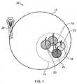
- Figure 1illustrates a heterogeneous telecommunications network 10 comprising a macro cell 12 and a cluster of small cells 14.
- the cluster of small cells 14comprises a first small cell 16, a second small cell 18, a third small cell 20, a fourth small cell 22 and a fifth small cell 24.
- the small cellsare distributed geographically to provide an area of coverage within the macro cell 12.
- User equipment(not shown) may roam through the network 10. When the user equipment is located within the macro cell 12, communications may be established between the user equipment and the macro cell base station 26 over an associated radio link. If the user equipment is located geographically within one of the small cells 16, 18, 20, 22 and 24, communications may be established between the user equipment and the base station of the associated small cell over an associated radio link.
- Figure 1shows only an example heterogeneous network and that a plurality of macro cells may be provided, more or less than five small cells may be provided and a plurality of small cell clusters may be provided.
- a plurality of small cell base stationswhich provide a plurality of small cells 16, 18, 20, 22, and 24.
- the small cellsprovide local communications coverage for a user in their vicinity.
- a handovermay occur between the base station 26 of the macro cell and the base station 28 of the small cell, when the base station of the small cell detects that user equipment has come within range.
- a handovermay occur between the base station of the current small cell and the base station of the new small cell, when the base station of the new small cell detects that user equipment has come within range.
- a user equipment in the telecommunications network 10 of Figure 1may be provided with dual connectivity support. That is, a user equipment may be connected to both the macro cell 12 and the small cell 16. Also, it should be appreciated that user equipment may be dual connected to small cell 16 and any of the other small cells 18 to 24.
- Figure 2shows proposed control plane architectures in which a user equipment (UE) is dual connected to a macro cell and a small cell,
- UEuser equipment
- a UE 100is dual connected to a macro cell 102 and a small cell 104.
- the macro cell 102is sometimes referred to as the anchor eNB and the small cell is sometimes referred to as the assisting eNB.
- An RRC entity 106is maintained in the UE 100 and an RRC entity 108 is maintained in the macro cell eNB 102.
- RRC signalingis transmitted arid received via radio resources provided by the macro cell 102.
- the small cell 104does not contain a RRC entity. It is therefore necessary for the small cell 104 to communicate-control plane/configuration information to the macro cell 102 using Layer 2/Layer 1 protocols, which must then in turn communicate this configuration information to the UE 100 using RRC communication protocols.
- the proposed architecture of Figure 2Ahas the disadvantage that it requires a new set of specifications for the inter-protocol layer communication between the RRC entity 108 located at the macro eNB 102 and the Layer 2 protocols located at the small cell 104.
- Such inter-protocol specificationsare not provided for in the current specification of LTE, as defined in 3GPP specification, TS 36 331 v11.3.0.
- a UE 110is dual connected to a macro cell 112 and a small cell 114.
- An RRC entity 116is maintained in the UE 110
- an RRC entity 118sometimes referred to as an anchor RRC entity
- an RRC entity 120is maintained in the small cell eNB 114.
- each node/cell involved in dual connectivitymaintains an RRC entity which partly interacts with the RRC entity 116 in the UE 110.
- RRC signalingcan be transmitted/received via radio recourses of the cell in which the corresponding function is maintained.
- RRC signalingcan be transmitted/received via radio recourses of the cell in which the corresponding function is maintained.
- a UE 130is dual connected to a macro cell 132 and a small cell 134.
- An RRC entity 138is maintained in the macro cell eNB 112 and an RRC entity 140 is maintained in the small cell eNB 114.
- the UE 130maintains a first RRC entity 142 corresponding to the macro cell 132 and a second RRC entity 144 corresponding to the small cell 134.
- an RRC entity per each node/cell involved in dual connectivityis maintained in the UE 130 and in the network.
- the RRC entitiescan be dependent or independent of each other.
- the mechanism for RRC transmission/reception signalling via radio recourses of the cellare similar those described in relation to Figure 2B .
- the RRC entities located at the macro and small celljointly provide the necessary lower parameter configuration for the lower protocol layer operations.
- the RRC entity at the small cellcontrols the functions and lower protocol parameters controlled by the small cell, while the RRC entity at the macro cell controls the global UE functions. Therefore, the RRC entity located at small cell is seen as secondary RRC entity while the RRC located at macro cell is seen as the primary RRC entity.
- From the functionality point of view operation of the control plane architectures of Figures 2B and 2Cis similar, the only difference being the RRC protocol modelling at the UE.
- RRCis modelled as a single RRC entity in Figure 2B while in Figure 2C , the RRC is modelled as two RRC entities.
- control plane architectures of Figures 2B and 2Chave the disadvantage that they require complex security architecture given that the RRC signal from the macro eNB and small cell eNB is required to be protected with sets of keys which are generated independently. This also increases the complexity at the UE.
- control plane architectures of Figures 2A, 2B and 2Chave a number of significant drawbacks. It is desirable to provide an RRC architecture which eliminates the problems seen in control plane architectures of Figures 2A, 2B and 2C for RRC protocol layer support for dual connectivity.
- FIG. 3shows a control plane architecture 200 according to a first embodiment.
- a UE 202is provided with two serving cells.
- UE 202is dual connected to a macro cell 204 (anchor eNB) and a small cell 206 (assisting eNB).
- anchor eNBanchor eNB
- small cell 206assisting eNB
- Both the macro cell 204 and the small cell 206will have RRC protocol functions/configuration information for the UE 202 during dual connectivity.
- the UE 202only has one RRC protocol entity/layer communicating with one of the serving cells, in the embodiment shown in Figure 3 , this is the macro cell 204.
- the UE 202has an RRC connection with the macro cell 204. This RRC connection is established between an RRC entity 208 maintained in the UE 202 and an RRC entity 210 maintained in the macro cell 204.
- the small cell 206must communicate its configuration information to the UE 202 via the macro cell 204.
- the macro cell 204may be considered to be a primary cell/node of the telecommunications network and the small cell 206 may be considered to be a secondary cell/node of the telecommunications network.
- the RRC entity 212 In the small cell 206may be considered to be a virtual RRC entity to the UE 202.
- the RRC entity 210 in the macro cell and the virtual RRC entity 212 in the small cellmay communicate over an Xx interface 214 between small and macro cells.
- This interface 214may be a modified version of the X2 interface, or may be a new interface not currently defined in the LTE specification or other backhaul link.
- the small cell 206may generate configuration information for the UE 202 and forward this configuration information to the macro cell RRC entity 210.
- the configuration informationmay be RRC configuration information and may comprise layer 3, layer 2, layer 1 configurations for the small cell.
- the virtual RRC protocol layer (entity) located at the small cell (assisting) eNBmay generate RRC configuration information relevant to the small cell including the small cell lower protocol parameter configuration, and may transmit this configuration information to the RRC entity 210 of the macro cell 204.
- the configuration informationmay be transmitted to the RRC entity 210 of the macro cell 204 in a transparent container. That is, the macro cell RRC entity 212 will not control the message in the transparent container and will not decode the configuration information delivered in the transparent container. The RRC entity 212 will simply forward the configuration information to the UE.
- the RRC entity 212 of the macro cellmay encapsulate the configuration information for transmission to the UE in an RRC configuration message.
- the RRC entity 212transmits the configuration information delivered from virtual RRC entity 212 of the small cell to the UE 202 over the Uu interface 216.
- the Uu interface 216may be an S1 communications interface or any other suitable radio interface.
- Ciphering and integrity protection for the configurationmay be performed at the macro cell 204 based on macro cell eNB security keys.
- the ciphering and integrity protection on the configuration informationmay be performed by the packet data convergence protocol (PDCP) located at the anchor eNB (layer L2).
- PDCPpacket data convergence protocol
- the UE 202decodes the configuration information/ RRC configuration message as it is received from the macro cell RRC entity 212, using security and transmission channel parameters of the macro cell eNB for the message decoding.
- RRC protocol located at the small cellmay be seen as virtual RRC layer to the UE.
- the lower layers (eg: layer2 /Layer 1) of small cellis controlled directly by the virtual RRC located at the small cell. Therefore, In the embodiment of Figure 3 , the need for additional specification to be provided for inter-protocol communication is eliminated as both the controller, the virtual RRC entity in the embodiment of Figure 3 , and the layer 2 protocols are located at the same cell, the small cell in the embodiment of Figure 3 .
- Figure 4shows the control place architecture 201 according to a second embodiment.
- the control information generationis the same as that described above in relation to Figure 3 , and like features share the same reference numerals.
- the transmission of the configuration information from the macro cell RRC entity 210 to the UE 202may additionally take a transmission path 218 via the small cell eNB 206.
- the virtual RRC entity 212 of the small cellmay generate configuration information and this may be transmitted to the RRC entity 210 of the macro cell over Xx interface 214.
- the RRC entitymay then transmit the configuration information to the UE 202 via the small cell over a transmission path 218.
- the transmission path 218may be an S1 communications interface or any other suitable radio interface.
- the small cell 206receives the configuration information from the RRC entity 210 of the macro cell over transmission path 218, and extracts the layer 2/layers 1 protocol information from the configuration information at a layer 2/layer 1 entity 219 and transmits this layer 2/layer 1 protocol information to the UE 202.
- the UE 202comprises a first layer 2/layer 1 protocol entity 220 associated with the macro cell 204 and a second layer 2/layer 1 protocol entity associated with the small cell 206.
- the second layer 2/layer 1 protocol entity 222receives the layer 2/layer 1 protocol information from the small cell 206 on transmission path 218, and decodes as necessary.
- Figure 4shows the UE 202 having first and second layer 2/layer 1 protocol entities, it should be appreciated that the function of these may be combined in a single layer 2/layer 1 protocol entity.
- layer 2/layer 1 protocol informationis sent form the small cell 206 to the UE 202 on transmission path 218, rather than RRC configuration information, the need for additional specification to be provided for inter-protocol communication is eliminated.
- transmission diversity for configuration information transmissionmay be provided, which may be beneficial should the configuration information experience different transmission qualities over different transmission paths.
- a cell identifiermay be transmitted together with the configuration information in the embodiments of Figures 3 and 4 , in order to identify the corresponding cell from which the configuration information relates.
- Figures 3 and 4are described with reference to downlink transmissions from the network to the UE, it will be appreciated that the embodiments are equally applicable to uplink transmission from the UE to the network.
- the UEmay generate configuration and this may be transmitted to the small cell via the macro cell.
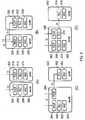
- Figure 5shows alternative architecture configurations for layer 2/layer 1 for the embodiments of Figure 3 and Figure 4 .
- the layer 2/layer 1 protocol architecture of Figure 3 and Figure 4may take any of the architecture option shown in Figures 5A, 5B, 5C and 5D .
- Figure 5Ashows the layer 2/layer 1 architecture for a macro cell 300 and a small cell 302.
- the macro cell 300comprises a Packet Data Convergence Protocol (PDCP) entity 304, a Radio Link Control (RLC) entity 306 and a Media Access Control (MAC) entity 308.
- the small cell 302comprises a PDCP entity 310, a RLC entity 312 and a MAC entity 314.
- both the PDCP entity 304 of the macro cell 300 and the PDCP entity 310 of the small cell 302receive information from core network with regards to the EPS bearer through S1 communications interfaces.
- Figure 5Bshows the layer 2/layer 1 architecture for a macro cell 320 and a small cell 322.
- the macro cell 320comprises a PDCP entity 324, a RLC entity 326 and a MAC entity 328.
- the small cell 322comprises a PDCP entity 330, a RLC entity 332 and a MAC entity 334.
- the PDCP entity 324 of the macro cell 320receives information through an S1 communications interface and the PDCP entity 330 of the small cell 322 receives information through an Xn interface, which may be a modified X2 interface, via the higher layer RRC protocol of the macro cell 320.
- Figure 5Cshows the layer 2/layer 1 architecture for a macro cell 340 and a small cell 342.
- the macro cell 340comprises a first PDCP entity 344 and a second PDCP entity 346, a RLC entity 348 and a MAC entity 350.
- the small cell 342comprises a RLC entity 352 and MAC entity 354.
- the first and second PDCP entities 344, 346 of the macro cell 340receive information through S1 communications interfaces.
- the RLC entity 352 of the small cell 342receives information through an Xn interface, which may be a modified X2 interface, from the second PDCP entity 346 of the macro cell 340.
- Figure 5Dshows the layer 2/layer 1 architecture for a macro cell 360 and a small cell 362.
- the macro cell 360comprises a first PDCP entity 364 and second PDCP entity 366, a first RLC entity 368 and a second RLC entity 370 and a MAC entity 372.
- the small cell 362comprises an RLC entity 374 and a MAC entity 376.
- the RLC entity 374is shown with a dotted line, because this RLC at the small cell may not perform the whole of RLC protocol functions/procedures and so may be considered to act as a sub-set of RLC.
- the first and second PDCP entities 364, 366 of the macro cell 360receive information through S1 communications interfaces.
- the RLC entity 374 of the small cell 362receives information through an Xn interface, which may be a modified X2 interface, from the second RLC entity 370 of the macro cell 360.
- Figure 5shows how lower level protocol control can be achieved in the architectures of the embodiments of Figures 3 and 4 .
- Figure 6shows how the lower protocol layers of the small cell of Figures 3 and 4 are controlled by the virtual RRC entity of the small cell.
- the virtual RRC entitymay directly control each of the PDCP entity, RLC entity and MAC entities of the small cell.
- the inter protocol layer communicationhere all occurs within the same node, it is not necessary to provide and additional control specifications for this inter-protocol layer communication.
- the inter-protocol layer communicationis left to the specific implementation at the small cell eNB.
- the messages or informationcould also be tagged with cell specific identification. This may take the form of implicit or explicit indication. if the messages and parameters for small cell is different from that of macro cell, the cell specific identification is implicitly indicated by the message or parameter itself.
Landscapes
- Engineering & Computer Science (AREA)
- Computer Networks & Wireless Communication (AREA)
- Signal Processing (AREA)
- Computer Security & Cryptography (AREA)
- Computer Hardware Design (AREA)
- Computing Systems (AREA)
- General Engineering & Computer Science (AREA)
- Mobile Radio Communication Systems (AREA)
Description
- The present invention relates to a telecommunications method for a telecommunications system comprising a user equipment in dual connection with a primary node and a secondary node, a telecommunications system, a primary node, a secondary node and to a user equipment.
- Small Cells are low power, low-cost base stations that are able to provide cellular service in residential or enterprise environments, with a typical coverage range of tens of metres. They have auto-configuration and self-optimization capabilities that enable a simple plug and play deployment, and are designed to automatically integrate themselves into an existing macrocellular network. Small cells, often referred to as pico cell, or metro cell, typically use the customer's broadband internet connection, for example DSL, cable or the like, as backhaul towards the macrocellular network. Support of non-ideal backhaul (with one way latency of few milliseconds to few tens of milliseconds) between small cells and between small cell and macro cells is considered as the typical deployment scenario.
- Small cell deployment for handling the capacity needs in high traffic areas, such as hot spot areas, is an area of current investigation. One proposal for handling the capacity needs in high traffic areas is to provide dual connectivity support for user equipment. Dual connectivity support allows a User Equipment (UE) to be connected concurrently connected to a macro cell and a small cell, or indeed to two small cells. In other words, the UE can be connected to more than one cell at a time and the UE can be served by more than one cell at a time. Dual connectivity support is considered as a way to enable offloading of traffic when required.
- However, dual connectivity support raises a number of issues relating to Radio Resource Control (RRC) plane architecture.
- It is desirable to provide a RRC architecture which simplifies UE implementation/operation as well as avoiding the need for inter-protocol communication over an open interface.
US2007049278 A1 discloses radio resource control signaling techniques for HSDPA systems, in which a radio network controller is operable in both a unicast signaling mode and a bi-cast signaling mode. The radio network controller is operable to go into bi-cast signaling mode during a hard handover. In the bi-cast signaling mode, the radio network controller is operable to send radio resource control messages to the mobile station through both the current serving cell and a target cell.- According to a first aspect of the invention, there is provided a telecommunications method for a telecommunications system comprising a user equipment in dual connection with a primary node and a secondary node, the method comprising: generating configuration information for the user equipment at a virtual radio resource control (RRC) entity of the secondary node or at the user equipment; transmitting the configuration information from the secondary node or the user equipment to a radio resource control entity of the primary node; and transmitting the configuration information from the primary node to the other of the user equipment or secondary node from where the configuration information is received.
- The proposed radio resource control plane architecture simplifies the UE implementation/operation as well as avoiding the need for inter-protocol communication specification, which is seen cumbersome when considering inter-vendor operation where the inter-protocol layer communication is usually left to the vendor specific macro cell eNB implementation.
- The method may further comprise generating configuration information at a radio resource control entity of the user equipment.
- The radio resource control entity of the primary node may include configuration information from the secondary node in a downlink radio resource control message sent to the user equipment.
- The downlink radio resource control message may be transmitted from the primary node to the user equipment using a radio resourcecontrol connection between the radio resource control entity of the primary node and the user equipment.
- The user equipment may decode theradio resourcecontrol message as it is received from the primary node, using security and transmission channel parameters of the primary node.
- The radio resourcecontrol entity of the primary node may include configuration information from the user equipment in an uplink radio resource control message sent to the secondary node.
- The method may further comprise transmitting the configuration information from the primary node to the user equipment via the secondary node, using layer 2 and/or layer 1 protocols or transmitting the configuration information to the secondary node via the user equipment, using layer 2 and/or layer 1 protocols.
- The configuration information may be transmitted from the secondary node or user equipment to the primary node in a transparent container, wherein the transparent container may be forwarded to the other of the user equipment and secondary node, without the primary node decoding the configuration information in the transparent container.
- The method may further comprise the primary node performing ciphering and/or integrity checks on the configuration information based on security keys. The ciphering and/or integrity checks may be performed by the packet data convergence protocol (PDCP) entity of the primary node.
- The configuration information may be transmitted from the secondary node to the radio resource control entity of the primary node using modified X2 communications protocols.
- An identification may be transmitted with the configuration informing, identifying the origin of the configuration information.
- The primary node may be a macro cell node and the secondary node is a small cell node.
- According to a second aspect of the invention, there is provided a telecommunications system, comprising: a primary node comprising a radio resource control (RRC) entity; a secondary node comprising a virtual radio resource control entity; and a user equipment in dual connection with the primary node and the secondary node, wherein the virtual radio resource control entity is operable to generate configuration information for the user equipment and transmit the configuration information to the radio resource control entity of the primary node, the user equipment is operable to generate configuration information and transmit the configuration information to the radio resource control entity of the primary node; and the radio resource control entity of the primary node is operable to transmit received configuration information to the other of the user equipment or secondary node from where the configuration information is received.
- According to a third aspect of the invention, there is provided a primary node of a telecommunications system comprising a user equipment in dual connection with the primary node and a secondary node, the primary node comprising: a radio resource control (RRC) entity operable to receive configuration information for the user equipment from a virtual radio resource control entity of the secondary node or from the user equipment, and operable to transmit the received configuration information to the other of the user equipment or secondary node from where the configuration information is received.
- According to a fourth aspect of the invention, there is provided a secondary node of a telecommunications system comprising a user equipment in dual connection with the secondary node and a primary node, the secondary node comprising: a virtual radio resource control (RRC) entity operable to generate configuration information for the user equipment and transmit the configuration information to a radio resource control entity of the primary node for subsequent transmission to the user equipment, and operable to receive configuration information from the user equipment via the radio resource control entity of the primary node.
- According to a fifth aspect of the invention, there is provided a user equipment of a telecommunications system comprising a primary node and a secondary node, wherein the user equipment is operable to be in dual communication with the primary node and the secondary node, and the user equipment is operable to receive a configuration information for the user equipment from the secondary node via a radio resource control (RRC) entity of the primary node, and is operable to generate configuration information and transmit the configuration information to the radio resource control entity of the primary node for subsequent transmission to the secondary node.
- According to a sixth aspect of the invention, there is provided a computer program product operable when executed on a computer to perform the method of the above first aspect.
- Further particular and preferred aspects of the invention are set out in the accompanying independent and dependent claims.
- Some embodiments of the apparatus and/or methods in accordance with embodiment of the present invention are now described, by way of example only, with reference to the accompanying drawings, in which:
Figure 1 shows an example of a telecommunicationsnetwork comprising a small cell cluster and a macro cell;Figure 2 shows proposed control plane architectures;Figure 3 shows the control plane architecture according to a first embodiment;Figure 4 shows the control place architecture according to a second embodiment;Figure 5 shows alternative architecture configurations of layer 2/layer 1; andFigure 6 shows the lower protocol layer control from the virtual RRC at the secondary/assisting cell.Figure 1 illustrates aheterogeneous telecommunications network 10 comprising amacro cell 12 and a cluster ofsmall cells 14. The cluster ofsmall cells 14 comprises a firstsmall cell 16, a secondsmall cell 18, a thirdsmall cell 20, a fourthsmall cell 22 and a fifthsmall cell 24. The small cells are distributed geographically to provide an area of coverage within themacro cell 12. User equipment (not shown) may roam through thenetwork 10. When the user equipment is located within themacro cell 12, communications may be established between the user equipment and the macrocell base station 26 over an associated radio link. If the user equipment is located geographically within one of thesmall cells Figure 1 shows only an example heterogeneous network and that a plurality of macro cells may be provided, more or less than five small cells may be provided and a plurality of small cell clusters may be provided.- As described above, within the
macro cell 12, there is provided a plurality of small cell base stations which provide a plurality ofsmall cells small cell 16, a handover may occur between thebase station 26 of the macro cell and the base station 28 of the small cell, when the base station of the small cell detects that user equipment has come within range. Likewise, as a user equipment comes within range of a different small cell, a handover may occur between the base station of the current small cell and the base station of the new small cell, when the base station of the new small cell detects that user equipment has come within range. - In order to handle the capacity needs of a high traffic area, a user equipment in the
telecommunications network 10 ofFigure 1 may be provided with dual connectivity support. That is, a user equipment may be connected to both themacro cell 12 and thesmall cell 16. Also, it should be appreciated that user equipment may be dual connected tosmall cell 16 and any of the othersmall cells 18 to 24. Figure 2 shows proposed control plane architectures in which a user equipment (UE) is dual connected to a macro cell and a small cell,- In
Figure 2A , a UE 100 is dual connected to amacro cell 102 and asmall cell 104. Themacro cell 102 is sometimes referred to as the anchor eNB and the small cell is sometimes referred to as the assisting eNB. AnRRC entity 106 is maintained in theUE 100 and anRRC entity 108 is maintained in the macro cell eNB 102. RRC signaling is transmitted arid received via radio resources provided by themacro cell 102. In the control plane architecture ofFigure 2A , thesmall cell 104 does not contain a RRC entity. It is therefore necessary for thesmall cell 104 to communicate-control plane/configuration information to themacro cell 102 using Layer 2/Layer 1 protocols,which must then in turn communicate this configuration information to theUE 100 using RRC communication protocols. - The proposed architecture of
Figure 2A has the disadvantage that it requires a new set of specifications for the inter-protocol layer communication between theRRC entity 108 located at the macro eNB 102 and the Layer 2 protocols located at thesmall cell 104. Such inter-protocol specifications are not provided for in the current specification of LTE, as defined in 3GPP specification, TS 36 331 v11.3.0. - In
Figure 2B , aUE 110 is dual connected to amacro cell 112 and asmall cell 114. AnRRC entity 116 is maintained in theUE 110, anRRC entity 118, sometimes referred to as an anchor RRC entity, is maintained in themacro cell eNB 112, and an RRC entity 120, sometimes referred to as an assisting RRC entity, is maintained in thesmall cell eNB 114. In the control plane architecture ofFigure 2B , each node/cell involved in dual connectivity maintains an RRC entity which partly interacts with theRRC entity 116 in theUE 110. - In
Figure 2B , RRC signaling can be transmitted/received via radio recourses of the cell in which the corresponding function is maintained. For example, it could be that physical radio resource configuration related parameters for thesmall cell 114 are controlled by and signaled from thesmall cell 114, whereas other parameters are controlled by and signaled from themacro cell 112. - In
Figure 2C , aUE 130 is dual connected to a macro cell 132 and asmall cell 134. AnRRC entity 138, is maintained in themacro cell eNB 112 and anRRC entity 140 is maintained in thesmall cell eNB 114. TheUE 130 maintains afirst RRC entity 142 corresponding to the macro cell 132 and asecond RRC entity 144 corresponding to thesmall cell 134. - In the control plane architecture of
Figure 2C , an RRC entity per each node/cell involved in dual connectivity is maintained in theUE 130 and in the network. The RRC entities can be dependent or independent of each other. The mechanism for RRC transmission/reception signalling via radio recourses of the cell are similar those described in relation toFigure 2B . - In the control plane architectures of
Figures 2B and 2C , the RRC entities located at the macro and small cell jointly provide the necessary lower parameter configuration for the lower protocol layer operations. The RRC entity at the small cell controls the functions and lower protocol parameters controlled by the small cell, while the RRC entity at the macro cell controls the global UE functions. Therefore, the RRC entity located at small cell is seen as secondary RRC entity while the RRC located at macro cell is seen as the primary RRC entity. From the functionality point of view operation of the control plane architectures ofFigures 2B and 2C is similar, the only difference being the RRC protocol modelling at the UE. RRC is modelled as a single RRC entity inFigure 2B while inFigure 2C , the RRC is modelled as two RRC entities. - The control plane architectures of
Figures 2B and 2C have the disadvantage that they require complex security architecture given that the RRC signal from the macro eNB and small cell eNB is required to be protected with sets of keys which are generated independently. This also increases the complexity at the UE. - As described above, the proposed control plane architectures of
Figures 2A, 2B and 2C have a number of significant drawbacks. It is desirable to provide an RRC architecture which eliminates the problems seen in control plane architectures ofFigures 2A, 2B and 2C for RRC protocol layer support for dual connectivity. Figure 3 shows acontrol plane architecture 200 according to a first embodiment. InFigure 3 , aUE 202 is provided with two serving cells.UE 202 is dual connected to a macro cell 204 (anchor eNB) and a small cell 206 (assisting eNB). It will be appreciated that althoughFigure 3 shows the UE in connection with a macro cell and a small cell, the UE may be in dual connection to a first and second small cell.- Both the
macro cell 204 and thesmall cell 206 will have RRC protocol functions/configuration information for theUE 202 during dual connectivity. However, theUE 202 only has one RRC protocol entity/layer communicating with one of the serving cells, in the embodiment shown inFigure 3 , this is themacro cell 204. InFigure 3 , theUE 202 has an RRC connection with themacro cell 204. This RRC connection is established between anRRC entity 208 maintained in theUE 202 and anRRC entity 210 maintained in themacro cell 204. - In other words, the
small cell 206 must communicate its configuration information to theUE 202 via themacro cell 204. In view of this, themacro cell 204 may be considered to be a primary cell/node of the telecommunications network and thesmall cell 206 may be considered to be a secondary cell/node of the telecommunications network. - As the
small cell 206 does not communicate RRC configuration information directly to theUE 202, theRRC entity 212 In thesmall cell 206 may be considered to be a virtual RRC entity to theUE 202. - The
RRC entity 210 in the macro cell and thevirtual RRC entity 212 in the small cell may communicate over anXx interface 214 between small and macro cells. Thisinterface 214 may be a modified version of the X2 interface, or may be a new interface not currently defined in the LTE specification or other backhaul link. - In the case that the
small cell 206 has configuration information to send to theUE 202, thesmall cell 206 may generate configuration information for theUE 202 and forward this configuration information to the macrocell RRC entity 210. The configuration information may be RRC configuration information and may comprise layer 3, layer 2, layer 1 configurations for the small cell. In other words, the virtual RRC protocol layer (entity) located at the small cell (assisting) eNB may generate RRC configuration information relevant to the small cell including the small cell lower protocol parameter configuration, and may transmit this configuration information to theRRC entity 210 of themacro cell 204. - The configuration information may be transmitted to the
RRC entity 210 of themacro cell 204 in a transparent container. That is, the macrocell RRC entity 212 will not control the message in the transparent container and will not decode the configuration information delivered in the transparent container. TheRRC entity 212 will simply forward the configuration information to the UE. - The
RRC entity 212 of the macro cell may encapsulate the configuration information for transmission to the UE in an RRC configuration message. TheRRC entity 212 transmits the configuration information delivered fromvirtual RRC entity 212 of the small cell to theUE 202 over theUu interface 216. TheUu interface 216 may be an S1 communications interface or any other suitable radio interface. - Ciphering and integrity protection for the configuration may be performed at the
macro cell 204 based on macro cell eNB security keys. The ciphering and integrity protection on the configuration information may be performed by the packet data convergence protocol (PDCP) located at the anchor eNB (layer L2). - The
UE 202 decodes the configuration information/ RRC configuration message as it is received from the macrocell RRC entity 212, using security and transmission channel parameters of the macro cell eNB for the message decoding. - In the above architecture RRC protocol located at the small cell may be seen as virtual RRC layer to the UE. However, the lower layers (eg: layer2 /Layer 1) of small cell is controlled directly by the virtual RRC located at the small cell. Therefore, In the embodiment of
Figure 3 , the need for additional specification to be provided for inter-protocol communication is eliminated as both the controller, the virtual RRC entity in the embodiment ofFigure 3 , and the layer 2 protocols are located at the same cell, the small cell in the embodiment ofFigure 3 . Figure 4 shows thecontrol place architecture 201 according to a second embodiment. In the embodiment ofFigure 4 , the control information generation is the same as that described above in relation toFigure 3 , and like features share the same reference numerals.- However, in
Figure 4 the transmission of the configuration information from the macrocell RRC entity 210 to theUE 202, may additionally take atransmission path 218 via thesmall cell eNB 206. - In other words, the
virtual RRC entity 212 of the small cell may generate configuration information and this may be transmitted to theRRC entity 210 of the macro cell overXx interface 214. The RRC entity may then transmit the configuration information to theUE 202 via the small cell over atransmission path 218. Thetransmission path 218 may be an S1 communications interface or any other suitable radio interface. - The
small cell 206 receives the configuration information from theRRC entity 210 of the macro cell overtransmission path 218, and extracts the layer 2/layers 1 protocol information from the configuration information at a layer 2/layer 1entity 219 and transmits this layer 2/layer 1 protocol information to theUE 202. - The
UE 202 comprises a first layer 2/layer 1protocol entity 220 associated with themacro cell 204 and a second layer 2/layer 1 protocol entity associated with thesmall cell 206. The second layer 2/layer 1protocol entity 222 receives the layer 2/layer 1 protocol information from thesmall cell 206 ontransmission path 218, and decodes as necessary. AlthoughFigure 4 shows theUE 202 having first and second layer 2/layer 1 protocol entities, it should be appreciated that the function of these may be combined in a single layer 2/layer 1 protocol entity. - As layer 2/layer 1 protocol information is sent form the
small cell 206 to theUE 202 ontransmission path 218, rather than RRC configuration information, the need for additional specification to be provided for inter-protocol communication is eliminated. - By providing this additional transmission path for the configuration information from the macro cell RRC entity, transmission diversity for configuration information transmission may be provided, which may be beneficial should the configuration information experience different transmission qualities over different transmission paths.
- It should also be appreciated that a cell identifier may be transmitted together with the configuration information in the embodiments of
Figures 3 and 4 , in order to identify the corresponding cell from which the configuration information relates. - Although
Figures 3 and 4 are described with reference to downlink transmissions from the network to the UE, it will be appreciated that the embodiments are equally applicable to uplink transmission from the UE to the network. In other words, the UE may generate configuration and this may be transmitted to the small cell via the macro cell. Figure 5 shows alternative architecture configurations for layer 2/layer 1 for the embodiments ofFigure 3 and Figure 4 . The layer 2/layer 1 protocol architecture ofFigure 3 and Figure 4 may take any of the architecture option shown inFigures 5A, 5B, 5C and 5D .Figure 5A shows the layer 2/layer 1 architecture for amacro cell 300 and asmall cell 302. Themacro cell 300 comprises a Packet Data Convergence Protocol (PDCP)entity 304, a Radio Link Control (RLC)entity 306 and a Media Access Control (MAC)entity 308. Thesmall cell 302 comprises aPDCP entity 310, aRLC entity 312 and aMAC entity 314. In the embodiment ofFigure 5A , both thePDCP entity 304 of themacro cell 300 and thePDCP entity 310 of thesmall cell 302 receive information from core network with regards to the EPS bearer through S1 communications interfaces.Figure 5B shows the layer 2/layer 1 architecture for amacro cell 320 and asmall cell 322. LikeFigure 5A , themacro cell 320 comprises aPDCP entity 324, aRLC entity 326 and aMAC entity 328. Thesmall cell 322 comprises aPDCP entity 330, aRLC entity 332 and aMAC entity 334. However; in the embodiment ofFigure 5B , thePDCP entity 324 of themacro cell 320 receives information through an S1 communications interface and thePDCP entity 330 of thesmall cell 322 receives information through an Xn interface, which may be a modified X2 interface, via the higher layer RRC protocol of themacro cell 320.Figure 5C shows the layer 2/layer 1 architecture for amacro cell 340 and asmall cell 342. InFigure 5C , themacro cell 340 comprises afirst PDCP entity 344 and asecond PDCP entity 346, aRLC entity 348 and aMAC entity 350. Thesmall cell 342 comprises aRLC entity 352 andMAC entity 354. In the embodiment ofFigure 5C , the first andsecond PDCP entities macro cell 340 receive information through S1 communications interfaces. TheRLC entity 352 of thesmall cell 342 receives information through an Xn interface, which may be a modified X2 interface, from thesecond PDCP entity 346 of themacro cell 340.Figure 5D shows the layer 2/layer 1 architecture for amacro cell 360 and asmall cell 362. InFigure 5D , themacro cell 360 comprises a first PDCP entity 364 andsecond PDCP entity 366, afirst RLC entity 368 and asecond RLC entity 370 and aMAC entity 372. Thesmall cell 362 comprises anRLC entity 374 and aMAC entity 376. TheRLC entity 374 is shown with a dotted line, because this RLC at the small cell may not perform the whole of RLC protocol functions/procedures and so may be considered to act as a sub-set of RLC. In the embodiment ofFigure 5D , the first andsecond PDCP entities 364, 366 of themacro cell 360 receive information through S1 communications interfaces. TheRLC entity 374 of thesmall cell 362 receives information through an Xn interface, which may be a modified X2 interface, from thesecond RLC entity 370 of themacro cell 360.Figure 5 shows how lower level protocol control can be achieved in the architectures of the embodiments ofFigures 3 and 4 .Figure 6 shows how the lower protocol layers of the small cell ofFigures 3 and 4 are controlled by the virtual RRC entity of the small cell. The virtual RRC entity may directly control each of the PDCP entity, RLC entity and MAC entities of the small cell. Given the inter protocol layer communication here all occurs within the same node, it is not necessary to provide and additional control specifications for this inter-protocol layer communication. The inter-protocol layer communication is left to the specific implementation at the small cell eNB.- In order to distinguish RRC messages which are corresponding to the macro cell from that of small cell, the messages or information could also be tagged with cell specific identification. This may take the form of implicit or explicit indication. if the messages and parameters for small cell is different from that of macro cell, the cell specific identification is implicitly indicated by the message or parameter itself.
- The present inventions may be embodied in other specific apparatus and/or methods. The described embodiments are to be considered in all respects as only illustrative and not restrictive. In particular, the scope of the invention is indicated by the appended claims rather than by the description and figures herein. All changes that come within the meaning and range of equivalency of the claims are to be embraced within their scope.
Claims (15)
- A telecommunications method for a telecommunications system comprising a user equipment (202) in dual connection with a primary node (204) and a secondary node (206), the method comprising:generating configuration information for the user equipment (202) at a virtual radio resource control entity (212) of the secondary node or at the user equipment (202);transmitting the configuration information from the secondary node (206) or the user equipment to a radio resource control entity (210) of the primary node (204); andtransmitting the configuration information from the primary node (204) to the other of the user equipment (202) or secondary node (206) from where the configuration information is received.
- A method according to Claim 1, wherein the radio resource control entity (210) of the primary node (204) includes configuration information from the secondary node (206) in a downlink radio resource control message sent to the user equipment (202).
- A method according to Claim 2, wherein the downlink radio resource control message is transmitted from the primary node (204) to the user equipment (202) using a radio resource control connection (216) between the radio resource control entity (210) of the primary node (204) and the user equipment (202).
- A method according to any preceding claim, wherein the user equipment (202) decodes the radio resource control message as it is received from the primary node (204), using security and transmission channel parameters of the primary node (204).
- A method according to Claim 1 or 2, wherein the radio resource control entity (210) of the primary node (204) includes configuration information from the user equipment (202) in an uplink radio resource control message sent to the secondary node (206).
- A method according to any preceding claim, further comprising transmitting the configuration information from the primary node (204) to the user equipment (202) via the secondary node (206), using layer 2 and/or layer 1 protocols or transmitting the configuration information to the secondary node (206) via the user equipment (202), using layer 2 and/or layer 1 protocols.
- A method according to any preceding claim, wherein the configuration information is transmitted from the secondary node (206) or user equipment (202) to the primary node (204) in a transparent container, wherein the transparent container is forwarded to the other of the user equipment (202) and secondary node (206), without the primary node (204) decoding the configuration information in the transparent container.
- A method according to any preceding claim, further comprising the primary node (204) performing ciphering and/or integrity checks on the configuration information based on security keys.
- A method according to any preceding claim, wherein the configuration information is transmitted from the secondary node (206) to the radio resource control entity (210) of the primary node (204) using modified X2 communications protocols.
- A method according to any preceding claim, wherein the primary node (204) is a macro cell node and the secondary node (206) is a small cell node.
- A telecommunications system (100), comprising:a primary node (204) comprising a radio resource control entity (210);a secondary node (206) comprising a virtual radio resource control entity (212); anda user equipment (202) in dual connection with the primary node (204) and the secondary node (206), whereinthe virtual radio resource control entity (212) is operable to generate configuration information for the user equipment and transmit the configuration information to the radio resource control entity (210) of the primary node (204), the user equipment is operable to generate configuration information and transmit the configuration information to the radio resource control entity (210) of the primary node; andthe radio resource control entity (210) of the primary node (204) is operable to transmit received configuration information to the other of the user equipment (202) or secondary node (206) from where the configuration information is received.
- A primary node (204) of a telecommunications system comprising a user equipment (202) in dual connection with the primary node (204) and a secondary node (206), the primary node comprising:a radio resource control entity (210) operable to receive configuration information for the user equipment (202) from a virtual radio resource control entity of the secondary node or from the user equipment (202), and operable to transmit the received configuration information to the other of the user equipment or secondary node from where the configuration information is received.
- A secondary node (206) of a telecommunications system comprising a user equipment (202) in dual connection with the secondary node (206) and a primary node (204), the secondary node comprising:a virtual radio resource control entity (212) operable to generate configuration information for the user equipment (202) and transmit the configuration information to a radio resource control entity of the primary node for subsequent transmission to the user equipment, and operable to receive configuration information from the user equipment (202) via the radio resource control entity of the primary node.
- A user equipment (202) of a telecommunications system comprising a primary node (204) and a secondary node (206), wheriein
the user equipment is operable to be in dual communication with the primary node and the secondary node, and
the user equipment (202) is operable to receive a configuration information for the user equipment (202) from a virtual radio resource control entity of the secondary node (206) via a radio resource contro entity of the primary node, and is operable to generate configuration information and transmit the configuration information to the radio resource control entity (210) of the primary node (204) for subsequent transmission to the secondary node; - A computer program product operable when executed on a computer to perform the method of any of claims 1 to 10.
Priority Applications (7)
| Application Number | Priority Date | Filing Date | Title |
|---|---|---|---|
| EP13360009.8AEP2806689B1 (en) | 2013-05-21 | 2013-05-21 | A telecommunications method, telecommunications system, primary node, secondary node and use equipment |
| US14/892,270US10779344B2 (en) | 2013-05-21 | 2014-03-27 | Telecommunications method, telecommunications system, primary node, secondary node and user equipment |
| PCT/EP2014/000850WO2014187515A1 (en) | 2013-05-21 | 2014-03-27 | A telecommunications method, telecommunications system, primary node, secondary node and user equipment |
| KR1020157035595AKR101804033B1 (en) | 2013-05-21 | 2014-03-27 | A telecommunications method, telecommunications system, primary node, secondary node and user equipment |
| CN201480029403.7ACN105230073A (en) | 2013-05-21 | 2014-03-27 | Telecommunication method, telecommunication system, primary node, secondary node and user equipment |
| JP2016514282AJP6219500B2 (en) | 2013-05-21 | 2014-03-27 | Telecommunication method, telecommunication system, primary node, secondary node and user equipment |
| CN202110001876.8ACN112738898A (en) | 2013-05-21 | 2014-03-27 | Telecommunication method, telecommunication system, primary node, secondary node and user equipment |
Applications Claiming Priority (1)
| Application Number | Priority Date | Filing Date | Title |
|---|---|---|---|
| EP13360009.8AEP2806689B1 (en) | 2013-05-21 | 2013-05-21 | A telecommunications method, telecommunications system, primary node, secondary node and use equipment |
Publications (2)
| Publication Number | Publication Date |
|---|---|
| EP2806689A1 EP2806689A1 (en) | 2014-11-26 |
| EP2806689B1true EP2806689B1 (en) | 2016-07-20 |
Family
ID=48626383
Family Applications (1)
| Application Number | Title | Priority Date | Filing Date |
|---|---|---|---|
| EP13360009.8AActiveEP2806689B1 (en) | 2013-05-21 | 2013-05-21 | A telecommunications method, telecommunications system, primary node, secondary node and use equipment |
Country Status (6)
| Country | Link |
|---|---|
| US (1) | US10779344B2 (en) |
| EP (1) | EP2806689B1 (en) |
| JP (1) | JP6219500B2 (en) |
| KR (1) | KR101804033B1 (en) |
| CN (2) | CN105230073A (en) |
| WO (1) | WO2014187515A1 (en) |
Families Citing this family (7)
| Publication number | Priority date | Publication date | Assignee | Title |
|---|---|---|---|---|
| WO2015146285A1 (en)* | 2014-03-25 | 2015-10-01 | ソニー株式会社 | Device |
| WO2016165127A1 (en)* | 2015-04-17 | 2016-10-20 | Mediatek Singapore Pte. Ltd. | Multiple conectivity in millimeter wave system |
| WO2017166300A1 (en) | 2016-04-01 | 2017-10-05 | 华为技术有限公司 | Method and apparatus for managing wireless resources |
| WO2018186782A1 (en)* | 2017-04-07 | 2018-10-11 | Telefonaktiebolaget Lm Ericsson (Publ) | Transport of rrc messages in dual connectivity communication |
| WO2020029074A1 (en)* | 2018-08-07 | 2020-02-13 | Oppo广东移动通信有限公司 | Wireless communication method, communication device, chip, and communication system |
| CN118612801A (en) | 2019-07-23 | 2024-09-06 | 北京三星通信技术研究有限公司 | A method for supporting switching in a mobile communication network |
| CN112312495B (en)* | 2019-07-23 | 2024-06-18 | 北京三星通信技术研究有限公司 | Method for supporting switching in mobile communication network |
Family Cites Families (24)
| Publication number | Priority date | Publication date | Assignee | Title |
|---|---|---|---|---|
| KR100407933B1 (en)* | 1998-11-11 | 2005-05-09 | 엘지전자 주식회사 | Handoff system between exchange |
| US7046678B2 (en)* | 2000-02-18 | 2006-05-16 | At & T Corp. | Channel efficiency based packet scheduling for interactive data in cellular networks |
| US8942706B2 (en)* | 2005-08-30 | 2015-01-27 | Telefonaktiebolaget Lm Ericsson (Publ) | Robust radio resource control signaling for HSDPA |
| CN101043714A (en)* | 2006-03-21 | 2007-09-26 | 华为技术有限公司 | Method and system for realizing mobility management of user equipment |
| US7957349B2 (en) | 2006-09-20 | 2011-06-07 | Samsung Electronics Co., Ltd | Handover method and apparatus in a mobile communication system |
| KR101384865B1 (en)* | 2007-01-09 | 2014-04-16 | 엘지전자 주식회사 | Random access method for enhancing contention resolution |
| US9392504B2 (en)* | 2007-06-19 | 2016-07-12 | Qualcomm Incorporated | Delivery of handover command |
| EP2028900A1 (en) | 2007-08-21 | 2009-02-25 | Nokia Siemens Networks Oy | Handover of a user equipment with forwarding and reusing a user equipment configuration |
| US9338811B2 (en)* | 2009-03-06 | 2016-05-10 | Apple Inc. | Methods and apparatus for providing selective access to wireless network resources using detailed information |
| US8532056B2 (en)* | 2009-04-13 | 2013-09-10 | Qualcomm Incorporated | Device mobility for split-cell relay networks |
| US8938247B2 (en)* | 2009-04-23 | 2015-01-20 | Qualcomm Incorporated | Sounding reference signal for coordinated multi-point operation |
| US8615013B2 (en)* | 2010-05-18 | 2013-12-24 | Agere Systems Llc | Packet scheduling with guaranteed minimum rate in a traffic manager of a network processor |
| GB2474077B (en)* | 2009-10-05 | 2013-07-24 | Samsung Electronics Co Ltd | Method and apparatus for configuring radio access functionality of a wireless commumication unit |
| EP2524437B1 (en)* | 2010-01-11 | 2019-05-22 | BlackBerry Limited | Control channel interference management and extended pdcch |
| CN108124287B (en) | 2010-02-12 | 2021-07-20 | 交互数字技术公司 | Wireless transmit and receive unit WTRU and method |
| EP2381719A1 (en)* | 2010-04-23 | 2011-10-26 | Alcatel- Lucent Shanghai Bell Co., Ltd | Configuration determination |
| US8989140B2 (en)* | 2010-06-28 | 2015-03-24 | Qualcomm Incorporated | System and method for mobility in a multi-point HSDPA communication network |
| US8934439B2 (en)* | 2010-07-15 | 2015-01-13 | Rivada Networks, Llc | Methods and systems for dynamic spectrum arbitrage based on a geographical area |
| CN105357773B (en)* | 2011-07-15 | 2020-06-02 | 华为技术有限公司 | A wireless broadband communication method, device and system |
| CN102932908B (en)* | 2011-08-12 | 2016-03-23 | 上海贝尔股份有限公司 | Control subscriber equipment in the method from the uplink on cell set Zhong Cong community |
| EP3541005A1 (en)* | 2012-03-23 | 2019-09-18 | HFI Innovation Inc. | Methods for multi-point carrier aggregation configuration and data forwarding |
| US9628251B2 (en)* | 2012-11-29 | 2017-04-18 | Mediatek, Inc. | UE measurement enhancement in adaptive TDD configuration networks |
| US9173147B2 (en)* | 2013-01-18 | 2015-10-27 | Blackberry Limited | Communicating data using a local wireless access network node |
| KR20140107088A (en)* | 2013-02-27 | 2014-09-04 | 주식회사 케이티 | Methods and apparatuses for transmitting buffer status report of a user equipment in small cell deployments |
- 2013
- 2013-05-21EPEP13360009.8Apatent/EP2806689B1/enactiveActive
- 2014
- 2014-03-27CNCN201480029403.7Apatent/CN105230073A/enactivePending
- 2014-03-27WOPCT/EP2014/000850patent/WO2014187515A1/enactiveApplication Filing
- 2014-03-27CNCN202110001876.8Apatent/CN112738898A/enactivePending
- 2014-03-27KRKR1020157035595Apatent/KR101804033B1/enactiveActive
- 2014-03-27JPJP2016514282Apatent/JP6219500B2/enactiveActive
- 2014-03-27USUS14/892,270patent/US10779344B2/enactiveActive
Also Published As
| Publication number | Publication date |
|---|---|
| WO2014187515A1 (en) | 2014-11-27 |
| EP2806689A1 (en) | 2014-11-26 |
| JP6219500B2 (en) | 2017-10-25 |
| US10779344B2 (en) | 2020-09-15 |
| KR101804033B1 (en) | 2017-12-01 |
| CN105230073A (en) | 2016-01-06 |
| US20160113052A1 (en) | 2016-04-21 |
| JP2016522638A (en) | 2016-07-28 |
| CN112738898A (en) | 2021-04-30 |
| KR20160009056A (en) | 2016-01-25 |
Similar Documents
| Publication | Publication Date | Title |
|---|---|---|
| US10721118B2 (en) | Method for configuring dual-connectivity by terminal, and apparatus therefor | |
| USRE47613E1 (en) | System and method for primary point handovers | |
| US10736009B2 (en) | Handover method and apparatus | |
| EP2806689B1 (en) | A telecommunications method, telecommunications system, primary node, secondary node and use equipment | |
| EP3496448A1 (en) | Cell configuration method and device | |
| EP3198940B1 (en) | Network device, terminal device and methods for facilitating handover of terminal device | |
| US10582381B2 (en) | Implementing radio access network slicing in a mobile network | |
| WO2018171573A1 (en) | Group handover methods and systems | |
| US20230189101A1 (en) | Methods and Apparatus for Change of Connection Link Involving Sidelink Relays | |
| KR20180004393A (en) | Methods for transmitting and receiving a data in Dual connectivity and Apparatuses thereof | |
| US11283777B2 (en) | Wireless telecommunications apparatus and methods | |
| EP2596656B1 (en) | Method and apparatus for interference management in heterogenous networks | |
| EP2836047B1 (en) | Method and system for initiating data transmission, a secundary node and computer program product | |
| EP3886511A2 (en) | Message identification method and apparatus | |
| CN105228171A (en) | The self-configuration method of the little base station of dual link and system in heterogeneous network | |
| US10880937B2 (en) | Method and devices for connecting a user equipment with a radio access network in a telecommunication network | |
| US10588066B2 (en) | Traffic offload | |
| CN117998442A (en) | Method performed by a first user equipment or a first network node and corresponding device | |
| EP3311599B1 (en) | Ultra dense network security architecture and method | |
| JP6470693B2 (en) | Communication control method and base station |
Legal Events
| Date | Code | Title | Description |
|---|---|---|---|
| PUAI | Public reference made under article 153(3) epc to a published international application that has entered the european phase | Free format text:ORIGINAL CODE: 0009012 | |
| 17P | Request for examination filed | Effective date:20140319 | |
| AK | Designated contracting states | Kind code of ref document:A1 Designated state(s):AL AT BE BG CH CY CZ DE DK EE ES FI FR GB GR HR HU IE IS IT LI LT LU LV MC MK MT NL NO PL PT RO RS SE SI SK SM TR | |
| AX | Request for extension of the european patent | Extension state:BA ME | |
| RBV | Designated contracting states (corrected) | Designated state(s):AL AT BE BG CH CY CZ DE DK EE ES FI FR GB GR HR HU IE IS IT LI LT LU LV MC MK MT NL NO PL PT RO RS SE SI SK SM TR | |
| GRAP | Despatch of communication of intention to grant a patent | Free format text:ORIGINAL CODE: EPIDOSNIGR1 | |
| INTG | Intention to grant announced | Effective date:20151014 | |
| INTG | Intention to grant announced | Effective date:20160205 | |
| GRAS | Grant fee paid | Free format text:ORIGINAL CODE: EPIDOSNIGR3 | |
| GRAA | (expected) grant | Free format text:ORIGINAL CODE: 0009210 | |
| AK | Designated contracting states | Kind code of ref document:B1 Designated state(s):AL AT BE BG CH CY CZ DE DK EE ES FI FR GB GR HR HU IE IS IT LI LT LU LV MC MK MT NL NO PL PT RO RS SE SI SK SM TR | |
| REG | Reference to a national code | Ref country code:GB Ref legal event code:FG4D | |
| REG | Reference to a national code | Ref country code:CH Ref legal event code:EP | |
| REG | Reference to a national code | Ref country code:IE Ref legal event code:FG4D | |
| REG | Reference to a national code | Ref country code:AT Ref legal event code:REF Ref document number:814947 Country of ref document:AT Kind code of ref document:T Effective date:20160815 | |
| REG | Reference to a national code | Ref country code:DE Ref legal event code:R096 Ref document number:602013009559 Country of ref document:DE | |
| REG | Reference to a national code | Ref country code:LT Ref legal event code:MG4D | |
| REG | Reference to a national code | Ref country code:NL Ref legal event code:MP Effective date:20160720 | |
| REG | Reference to a national code | Ref country code:AT Ref legal event code:MK05 Ref document number:814947 Country of ref document:AT Kind code of ref document:T Effective date:20160720 | |
| PG25 | Lapsed in a contracting state [announced via postgrant information from national office to epo] | Ref country code:HR Free format text:LAPSE BECAUSE OF FAILURE TO SUBMIT A TRANSLATION OF THE DESCRIPTION OR TO PAY THE FEE WITHIN THE PRESCRIBED TIME-LIMIT Effective date:20160720 Ref country code:LT Free format text:LAPSE BECAUSE OF FAILURE TO SUBMIT A TRANSLATION OF THE DESCRIPTION OR TO PAY THE FEE WITHIN THE PRESCRIBED TIME-LIMIT Effective date:20160720 Ref country code:IS Free format text:LAPSE BECAUSE OF FAILURE TO SUBMIT A TRANSLATION OF THE DESCRIPTION OR TO PAY THE FEE WITHIN THE PRESCRIBED TIME-LIMIT Effective date:20161120 Ref country code:RS Free format text:LAPSE BECAUSE OF FAILURE TO SUBMIT A TRANSLATION OF THE DESCRIPTION OR TO PAY THE FEE WITHIN THE PRESCRIBED TIME-LIMIT Effective date:20160720 Ref country code:NO Free format text:LAPSE BECAUSE OF FAILURE TO SUBMIT A TRANSLATION OF THE DESCRIPTION OR TO PAY THE FEE WITHIN THE PRESCRIBED TIME-LIMIT Effective date:20161020 Ref country code:FI Free format text:LAPSE BECAUSE OF FAILURE TO SUBMIT A TRANSLATION OF THE DESCRIPTION OR TO PAY THE FEE WITHIN THE PRESCRIBED TIME-LIMIT Effective date:20160720 Ref country code:IT Free format text:LAPSE BECAUSE OF FAILURE TO SUBMIT A TRANSLATION OF THE DESCRIPTION OR TO PAY THE FEE WITHIN THE PRESCRIBED TIME-LIMIT Effective date:20160720 Ref country code:NL Free format text:LAPSE BECAUSE OF FAILURE TO SUBMIT A TRANSLATION OF THE DESCRIPTION OR TO PAY THE FEE WITHIN THE PRESCRIBED TIME-LIMIT Effective date:20160720 | |
| PG25 | Lapsed in a contracting state [announced via postgrant information from national office to epo] | Ref country code:ES Free format text:LAPSE BECAUSE OF FAILURE TO SUBMIT A TRANSLATION OF THE DESCRIPTION OR TO PAY THE FEE WITHIN THE PRESCRIBED TIME-LIMIT Effective date:20160720 Ref country code:BE Free format text:LAPSE BECAUSE OF FAILURE TO SUBMIT A TRANSLATION OF THE DESCRIPTION OR TO PAY THE FEE WITHIN THE PRESCRIBED TIME-LIMIT Effective date:20160720 Ref country code:AT Free format text:LAPSE BECAUSE OF FAILURE TO SUBMIT A TRANSLATION OF THE DESCRIPTION OR TO PAY THE FEE WITHIN THE PRESCRIBED TIME-LIMIT Effective date:20160720 Ref country code:GR Free format text:LAPSE BECAUSE OF FAILURE TO SUBMIT A TRANSLATION OF THE DESCRIPTION OR TO PAY THE FEE WITHIN THE PRESCRIBED TIME-LIMIT Effective date:20161021 Ref country code:PT Free format text:LAPSE BECAUSE OF FAILURE TO SUBMIT A TRANSLATION OF THE DESCRIPTION OR TO PAY THE FEE WITHIN THE PRESCRIBED TIME-LIMIT Effective date:20161121 Ref country code:PL Free format text:LAPSE BECAUSE OF FAILURE TO SUBMIT A TRANSLATION OF THE DESCRIPTION OR TO PAY THE FEE WITHIN THE PRESCRIBED TIME-LIMIT Effective date:20160720 Ref country code:SE Free format text:LAPSE BECAUSE OF FAILURE TO SUBMIT A TRANSLATION OF THE DESCRIPTION OR TO PAY THE FEE WITHIN THE PRESCRIBED TIME-LIMIT Effective date:20160720 Ref country code:LV Free format text:LAPSE BECAUSE OF FAILURE TO SUBMIT A TRANSLATION OF THE DESCRIPTION OR TO PAY THE FEE WITHIN THE PRESCRIBED TIME-LIMIT Effective date:20160720 | |
| REG | Reference to a national code | Ref country code:DE Ref legal event code:R097 Ref document number:602013009559 Country of ref document:DE | |
| PG25 | Lapsed in a contracting state [announced via postgrant information from national office to epo] | Ref country code:EE Free format text:LAPSE BECAUSE OF FAILURE TO SUBMIT A TRANSLATION OF THE DESCRIPTION OR TO PAY THE FEE WITHIN THE PRESCRIBED TIME-LIMIT Effective date:20160720 Ref country code:RO Free format text:LAPSE BECAUSE OF FAILURE TO SUBMIT A TRANSLATION OF THE DESCRIPTION OR TO PAY THE FEE WITHIN THE PRESCRIBED TIME-LIMIT Effective date:20160720 | |
| REG | Reference to a national code | Ref country code:FR Ref legal event code:PLFP Year of fee payment:5 | |
| PLBE | No opposition filed within time limit | Free format text:ORIGINAL CODE: 0009261 | |
| STAA | Information on the status of an ep patent application or granted ep patent | Free format text:STATUS: NO OPPOSITION FILED WITHIN TIME LIMIT | |
| PG25 | Lapsed in a contracting state [announced via postgrant information from national office to epo] | Ref country code:CZ Free format text:LAPSE BECAUSE OF FAILURE TO SUBMIT A TRANSLATION OF THE DESCRIPTION OR TO PAY THE FEE WITHIN THE PRESCRIBED TIME-LIMIT Effective date:20160720 Ref country code:DK Free format text:LAPSE BECAUSE OF FAILURE TO SUBMIT A TRANSLATION OF THE DESCRIPTION OR TO PAY THE FEE WITHIN THE PRESCRIBED TIME-LIMIT Effective date:20160720 Ref country code:SK Free format text:LAPSE BECAUSE OF FAILURE TO SUBMIT A TRANSLATION OF THE DESCRIPTION OR TO PAY THE FEE WITHIN THE PRESCRIBED TIME-LIMIT Effective date:20160720 Ref country code:BG Free format text:LAPSE BECAUSE OF FAILURE TO SUBMIT A TRANSLATION OF THE DESCRIPTION OR TO PAY THE FEE WITHIN THE PRESCRIBED TIME-LIMIT Effective date:20161020 Ref country code:SM Free format text:LAPSE BECAUSE OF FAILURE TO SUBMIT A TRANSLATION OF THE DESCRIPTION OR TO PAY THE FEE WITHIN THE PRESCRIBED TIME-LIMIT Effective date:20160720 | |
| 26N | No opposition filed | Effective date:20170421 | |
| PG25 | Lapsed in a contracting state [announced via postgrant information from national office to epo] | Ref country code:SI Free format text:LAPSE BECAUSE OF FAILURE TO SUBMIT A TRANSLATION OF THE DESCRIPTION OR TO PAY THE FEE WITHIN THE PRESCRIBED TIME-LIMIT Effective date:20160720 Ref country code:LU Free format text:LAPSE BECAUSE OF NON-PAYMENT OF DUE FEES Effective date:20170531 | |
| REG | Reference to a national code | Ref country code:CH Ref legal event code:PL | |
| PG25 | Lapsed in a contracting state [announced via postgrant information from national office to epo] | Ref country code:MC Free format text:LAPSE BECAUSE OF FAILURE TO SUBMIT A TRANSLATION OF THE DESCRIPTION OR TO PAY THE FEE WITHIN THE PRESCRIBED TIME-LIMIT Effective date:20160720 | |
| REG | Reference to a national code | Ref country code:IE Ref legal event code:MM4A | |
| PG25 | Lapsed in a contracting state [announced via postgrant information from national office to epo] | Ref country code:LI Free format text:LAPSE BECAUSE OF NON-PAYMENT OF DUE FEES Effective date:20170531 Ref country code:CH Free format text:LAPSE BECAUSE OF NON-PAYMENT OF DUE FEES Effective date:20170531 | |
| PG25 | Lapsed in a contracting state [announced via postgrant information from national office to epo] | Ref country code:LU Free format text:LAPSE BECAUSE OF NON-PAYMENT OF DUE FEES Effective date:20170521 | |
| PG25 | Lapsed in a contracting state [announced via postgrant information from national office to epo] | Ref country code:IE Free format text:LAPSE BECAUSE OF NON-PAYMENT OF DUE FEES Effective date:20170521 | |
| REG | Reference to a national code | Ref country code:FR Ref legal event code:PLFP Year of fee payment:6 | |
| PG25 | Lapsed in a contracting state [announced via postgrant information from national office to epo] | Ref country code:MT Free format text:LAPSE BECAUSE OF NON-PAYMENT OF DUE FEES Effective date:20170521 | |
| PG25 | Lapsed in a contracting state [announced via postgrant information from national office to epo] | Ref country code:AL Free format text:LAPSE BECAUSE OF FAILURE TO SUBMIT A TRANSLATION OF THE DESCRIPTION OR TO PAY THE FEE WITHIN THE PRESCRIBED TIME-LIMIT Effective date:20160720 | |
| REG | Reference to a national code | Ref country code:DE Ref legal event code:R082 Ref document number:602013009559 Country of ref document:DE Representative=s name:LOUIS POEHLAU LOHRENTZ PATENTANWAELTE PARTNERS, DE Ref country code:DE Ref legal event code:R082 Ref document number:602013009559 Country of ref document:DE Representative=s name:LOUIS, POEHLAU, LOHRENTZ, DE Ref country code:DE Ref legal event code:R081 Ref document number:602013009559 Country of ref document:DE Owner name:NOKIA TECHNOLOGIES OY, FI Free format text:FORMER OWNER: ALCATEL LUCENT, BOULOGNE BILLANCOURT, FR | |
| PG25 | Lapsed in a contracting state [announced via postgrant information from national office to epo] | Ref country code:HU Free format text:LAPSE BECAUSE OF FAILURE TO SUBMIT A TRANSLATION OF THE DESCRIPTION OR TO PAY THE FEE WITHIN THE PRESCRIBED TIME-LIMIT; INVALID AB INITIO Effective date:20130521 | |
| PG25 | Lapsed in a contracting state [announced via postgrant information from national office to epo] | Ref country code:CY Free format text:LAPSE BECAUSE OF FAILURE TO SUBMIT A TRANSLATION OF THE DESCRIPTION OR TO PAY THE FEE WITHIN THE PRESCRIBED TIME-LIMIT Effective date:20160720 | |
| PG25 | Lapsed in a contracting state [announced via postgrant information from national office to epo] | Ref country code:MK Free format text:LAPSE BECAUSE OF FAILURE TO SUBMIT A TRANSLATION OF THE DESCRIPTION OR TO PAY THE FEE WITHIN THE PRESCRIBED TIME-LIMIT Effective date:20160720 | |
| PG25 | Lapsed in a contracting state [announced via postgrant information from national office to epo] | Ref country code:TR Free format text:LAPSE BECAUSE OF FAILURE TO SUBMIT A TRANSLATION OF THE DESCRIPTION OR TO PAY THE FEE WITHIN THE PRESCRIBED TIME-LIMIT Effective date:20160720 | |
| REG | Reference to a national code | Ref country code:GB Ref legal event code:732E Free format text:REGISTERED BETWEEN 20200402 AND 20200408 | |
| REG | Reference to a national code | Ref country code:FR Ref legal event code:PLFP Year of fee payment:11 | |
| PGFP | Annual fee paid to national office [announced via postgrant information from national office to epo] | Ref country code:DE Payment date:20250402 Year of fee payment:13 | |
| PGFP | Annual fee paid to national office [announced via postgrant information from national office to epo] | Ref country code:GB Payment date:20250401 Year of fee payment:13 | |
| PGFP | Annual fee paid to national office [announced via postgrant information from national office to epo] | Ref country code:FR Payment date:20250401 Year of fee payment:13 |