EP2805200B1 - Compact eye-tracked head-mounted display - Google Patents
Compact eye-tracked head-mounted displayDownload PDFInfo
- Publication number
- EP2805200B1 EP2805200B1EP13740989.2AEP13740989AEP2805200B1EP 2805200 B1EP2805200 B1EP 2805200B1EP 13740989 AEP13740989 AEP 13740989AEP 2805200 B1EP2805200 B1EP 2805200B1
- Authority
- EP
- European Patent Office
- Prior art keywords
- eye
- display
- optical
- mounted display
- tracked head
- Prior art date
- Legal status (The legal status is an assumption and is not a legal conclusion. Google has not performed a legal analysis and makes no representation as to the accuracy of the status listed.)
- Active
Links
Images


Classifications
- G—PHYSICS
- G02—OPTICS
- G02B—OPTICAL ELEMENTS, SYSTEMS OR APPARATUS
- G02B27/00—Optical systems or apparatus not provided for by any of the groups G02B1/00 - G02B26/00, G02B30/00
- G02B27/01—Head-up displays
- G02B27/017—Head mounted
- G02B27/0172—Head mounted characterised by optical features
- G—PHYSICS
- G02—OPTICS
- G02B—OPTICAL ELEMENTS, SYSTEMS OR APPARATUS
- G02B17/00—Systems with reflecting surfaces, with or without refracting elements
- G02B17/08—Catadioptric systems
- G02B17/0856—Catadioptric systems comprising a refractive element with a reflective surface, the reflection taking place inside the element, e.g. Mangin mirrors
- G02B17/086—Catadioptric systems comprising a refractive element with a reflective surface, the reflection taking place inside the element, e.g. Mangin mirrors wherein the system is made of a single block of optical material, e.g. solid catadioptric systems
- G—PHYSICS
- G02—OPTICS
- G02B—OPTICAL ELEMENTS, SYSTEMS OR APPARATUS
- G02B17/00—Systems with reflecting surfaces, with or without refracting elements
- G02B17/08—Catadioptric systems
- G02B17/0896—Catadioptric systems with variable magnification or multiple imaging planes, including multispectral systems
- G—PHYSICS
- G02—OPTICS
- G02B—OPTICAL ELEMENTS, SYSTEMS OR APPARATUS
- G02B27/00—Optical systems or apparatus not provided for by any of the groups G02B1/00 - G02B26/00, G02B30/00
- G02B27/0093—Optical systems or apparatus not provided for by any of the groups G02B1/00 - G02B26/00, G02B30/00 with means for monitoring data relating to the user, e.g. head-tracking, eye-tracking
- G—PHYSICS
- G02—OPTICS
- G02B—OPTICAL ELEMENTS, SYSTEMS OR APPARATUS
- G02B27/00—Optical systems or apparatus not provided for by any of the groups G02B1/00 - G02B26/00, G02B30/00
- G02B27/01—Head-up displays
- G02B27/017—Head mounted
- G—PHYSICS
- G02—OPTICS
- G02B—OPTICAL ELEMENTS, SYSTEMS OR APPARATUS
- G02B5/00—Optical elements other than lenses
- G02B5/04—Prisms
- G—PHYSICS
- G06—COMPUTING OR CALCULATING; COUNTING
- G06F—ELECTRIC DIGITAL DATA PROCESSING
- G06F3/00—Input arrangements for transferring data to be processed into a form capable of being handled by the computer; Output arrangements for transferring data from processing unit to output unit, e.g. interface arrangements
- G06F3/01—Input arrangements or combined input and output arrangements for interaction between user and computer
- G06F3/011—Arrangements for interaction with the human body, e.g. for user immersion in virtual reality
- G06F3/013—Eye tracking input arrangements
- G—PHYSICS
- G02—OPTICS
- G02B—OPTICAL ELEMENTS, SYSTEMS OR APPARATUS
- G02B27/00—Optical systems or apparatus not provided for by any of the groups G02B1/00 - G02B26/00, G02B30/00
- G02B27/01—Head-up displays
- G02B27/0101—Head-up displays characterised by optical features
- G02B2027/011—Head-up displays characterised by optical features comprising device for correcting geometrical aberrations, distortion
- G—PHYSICS
- G02—OPTICS
- G02B—OPTICAL ELEMENTS, SYSTEMS OR APPARATUS
- G02B27/00—Optical systems or apparatus not provided for by any of the groups G02B1/00 - G02B26/00, G02B30/00
- G02B27/01—Head-up displays
- G02B27/0101—Head-up displays characterised by optical features
- G02B2027/0138—Head-up displays characterised by optical features comprising image capture systems, e.g. camera
- G—PHYSICS
- G02—OPTICS
- G02B—OPTICAL ELEMENTS, SYSTEMS OR APPARATUS
- G02B27/00—Optical systems or apparatus not provided for by any of the groups G02B1/00 - G02B26/00, G02B30/00
- G02B27/01—Head-up displays
- G02B27/0179—Display position adjusting means not related to the information to be displayed
- G02B2027/0187—Display position adjusting means not related to the information to be displayed slaved to motion of at least a part of the body of the user, e.g. head, eye
Definitions
- the present inventionrelates generally to eye-tracked head-mounted displays, and more particularly, but not exclusively, to eye-tracked head-mounted displays which may utilize the same optics for eyetracking and image viewing, with a selected portion of the optics used for an eyetracking optical path and a selected portion of the display optics used for an image viewing optical path.
- Head-mounted display (HMD) technologieshave been applied to a wide range of scientific and engineering domains. Examples of applications include flight simulation, scientific visualization, medicine, engineering design, education and training, wearable computing, and entertainment systems.
- HMDsare one of the enabling technologies for merging virtual views with physical scenes, which may enable a physician to see a 3D rendering of the anatomical structures or CT images of a patient superimposed onto the patient's anatomy, such as the abdomen, for example.
- an HMDcreates a mobile display solution that offers much more attractive image quality and screen size than other popular mobile platforms such as smart phones and PDAs. In the foreseeable future, such mobile displays may appear as elegant as a pair of sunglasses and may become an integral part of many people's daily activities to retrieve information and connect with people instantly.
- ET-HMDeyetracked HMD
- An ET-HMDis able to display monocular or stereoscopic virtual images as a classical HMD does, while additionally tracking the gaze direction of the user.
- a fully-integrated ET-HMDoffers multi-fold benefits, not only to fundamental scientific research but also to emerging applications of such technology. For instance, many research efforts are concerned about how human users perceive and organize spatial information, interact with such information, and navigate within 3D virtual spaces. Eyetracking capability in HMDs adds a very valuable tool and objective metric for scientists to quantitatively assess user interaction with 3D environments and investigate the effectiveness of various 3D visualization technologies for various specific tasks including training, education, and augmented cognition tasks.
- Eyetracking capability integrated with HMD systemscan be utilized to improve size and depth perception accuracy in stereoscopic displays. Eyetracking capability may help to create solutions to the FOV-resolution tradeoff through a fovea-contingent display scheme and to the accommodation-convergence contradiction by using vari-focal plane display methodology.
- an ET-HMDoffers unique opportunities for novel interactive interfaces for people with proprioceptive disabilities where eye gaze instead of hands or feet can be used as a method of interaction and communication.
- Figure 1shows the first-order layout of the ET-HMD optical system, in which the optical system was simplified with ideal lens modules to emphasize the concept and the scale.
- Curatu, C., Hong Hua, and J. P. Rolland"Projection-based head-mounted display with eye-tracking capabilities," Proceedings of the SPIE International Society for Optical Engineering, Vol. 5875, San Diego, USA, August 2005 .
- Curatu, C., J.P. Rolland, and Hong Hua“Dual purpose lens for an eye-tracked projection head-mounted display," Proceedings of International Optical Design Conference, Vancouver, Canada, June 2006 .
- the designtook a full integration approach and combined most of the optical paths for the display and eyetracking subsystems.
- the same projection opticswas shared for both display and eye imaging functions.
- the main limitation of this designwas that the overall volume of the integrated ET-HMD system, although significantly improved over others, was still bulky and heavy.
- a head-mounted display involving an eye-tracking systemis disclosed in US 2001/009478 A1 .
- An ET-HMD system using a video-based feature tracking methodtypically requires at least three unique optical paths: an illumination path, an eye imaging path, and a virtual display path.
- an illumination paththe eye is illuminated by typically near infrared light-emitting diodes (NIR LEDs) to create imaging features such as darkened or brightened pupil and/or Purkinje features for tracking.
- NIR LEDsnear infrared light-emitting diodes
- an eye image with the tracking featuresis captured for feature detection and tracking.
- a virtual image displayed on a miniature display deviceis created through eyepiece optics for information viewing.
- One of the innovations of the present inventionis an optical scheme that can uniquely combine these three optical paths through the same core optics, which may be an eyepiece, projection lens, or other optics structure.
- the present inventionmay use freeform optical technology along with an innovative optical scheme that can uniquely combine eye imaging optics for eyetracking with the display optics for information viewing.
- display opticsand “imaging optics” may refer to the same physical optics, which physical optics may also be called the "core optics”.
- the eye illumination opticsmay also be combined.
- the present inventionavoids the limitation imposed by prior approaches where the optical systems for the HMD and eyetracking paths are treated separately, and where rotationally symmetric optical surfaces are mostly used.
- the optical scheme of integrating eyetracking with HMD disclosed in the present inventionis not limited to freeform optics.
- the core optics for the ET-HMD system in accordance with the present inventioncan be applied to conventional HMD optics.
- the eye-tracked head mounted displaymay include a stop at the first plane, where the stop has at least one aperture therein disposed at a location along the sensor optical path.
- the eye-tracked head-mounted displaymay include a stop having at least one aperture therein disposed at a location along the sensor optical path between the sensor and selected surface.
- the stop or aperturemay include a pin-hole like aperture.
- the display opticsmay include a freeform optical element, a rotationally symmetric optical element, and/or a freeform optical prism.
- the display opticsmay include an aspheric surface.
- the eye-tracked head-mounted displaymay include an illumination source for generating optical radiation to illuminate the second plane to effect illumination of the user's eye.
- the display opticsmay be configured to collimate the optical radiation from the illumination source.
- the illumination sourcemay be located in the first plane or at a different location, such as off axis from the optical axis of the display optics.
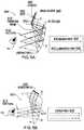
- Figure 3Aschematically illustrates an exemplary system layout 300 in accordance with the present invention for achieving a compact ET-HMD system.
- the same core optics 310may serve the functions of eye imaging, display viewing, and/or eye illumination. This simplification stems from an insightful observation on the unique conjugate planes in the eye illumination path 305, eye imaging path 307, and display path 309.
- differing portions along the clear aperture of the core optics 310may be used for the eye illumination path 305, eye imaging path 307, and display path 309.
- two or more of the eye illumination path 305, eye imaging path 307, and display path 309can impinge upon differing respective portions of the selected surface, though partial overlap is permitted.
- the core optics 310which in this context functions as display optics, forms a magnified virtual image of the microdisplay 320 seen by the eye 10.
- the microdisplay unit 320can be any type of self-emissive, or illuminated pixel arrays that can serve as an image source, including, but not limited to, a liquid crystal on silicon (LCoS) display device, a liquid crystal display (LCD) panel, an organic light emitting display (OLED), ferroelectric liquid crystal on silicon (FLCoS) device, digital mirror device (DMD), or a micro-projector built upon these aforementioned or other types of micro-display devices, and additional optional optics may be provided between the microdisplay 320 and core optics 310, as desired or required.
- LCDliquid crystal on silicon
- OLEDorganic light emitting display
- FLCoSferroelectric liquid crystal on silicon
- DMDdigital mirror device
- the magnified virtual imagewhich may appear to be at an infinite or finite distance from the eye 10, corresponds to the conjugate focal plane of the microdisplay 320.
- the eye pupil 12may be co-located with the exit pupil 312 of the display path 309.
- the chief rays of the display through the center of the pupil 12(shown in solid lines in Fig. 3A ) define the field height on the microdisplay 320, and thus they are separable on the microdisplay surface.
- NIR LEDsnear-infrared light-emitting diodes
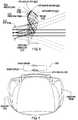
- 330may be mounted around the microdisplay 320 to illuminate the eye through the display/core optics 310, Fig. 3B .
- the display/core optics 310may collimate the LED light and create a uniformly illuminated area on the eye area through multiple virtual LED sources created through the display/core optics 310.
- Such an off-axis illumination arrangementcan create a dark-pupil effect and form multiple glint images of the NIR LEDs 330 through the reflection off the anterior cornea.
- the eye pupil 12becomes the object that needs to be imaged.
- a stop 340may be placed around the microdisplay 320.
- the chief rays of different object fields in the display pathbecome the marginal rays of the on-axis object point in the eye imaging path 307, and thus all the rays through the same point on the eye pupil 12 will be imaged onto the same point on the IR imaging sensor 360. These rays, however, intersect with the microdisplay surface at unique locations.
- a stop 340is properly designed and placed around the microdisplay 320 such that it does not affect the display path 309 and yet is sufficient to collect rays to form eye images in the eye imaging path 307.
- the stop 340may be provided in the form of pin-hole like small apertures 350 or may be a selected area surrounding the microdisplay 320.
- a separate image sensor 360may be associated with each pin-hole like aperture 350.
- the optical layout 300 for combining two or three unique optical functionshas applicability to virtually all types of optical structures suitable for HMD optics.
- an exemplary configuration with a conventional eyepiece optics based on rotationally symmetric optical elementshas been designed, as discussed below in connection with Fig. 16 .
- eyetracking function aspectspecifically, several different eyetracking techniques exist that may be used to monitor eye movements, which fall into three categories: electro-oclography, scleral search coil, and various video-based feature tracking approaches.
- electro-oclographyelectro-oclography
- scleral search coilvarious video-based feature tracking approaches.
- video-based feature trackingwhich detects and tracks features in captured eye images, can be the least intrusive and most convenient approach to track eye movement.
- the eye images 201, 202typically have two types of features that can be readily identified and measured, Figs. 2A, 2B .
- One featureis known as the first Purkinje image, or glint 6, which refers to the reflection image of a point light source formed by the anterior surface of the cornea, Fig. 2B .
- the second featureis the eye pupil 12.
- Figures 2A-2Bdemonstrate examples of IR-illuminated eye images 201, 202.
- an on-axis illumination strategywhere the IR illuminators are arranged nearly co-axial with the optical axis of the eye imaging optics leads to a bright pupil 2, Fig.
- an off-axis illumination strategywhere the IR illuminators are placed away from the optical axis of the eye imaging optics leads to a darkened pupil 4 with glint(s) 6, Fig. 2B .
- the pupil and glint featuresmay then be utilized for eye movement tracking.
- the pupil-corneal reflection tracking methodwhich relates the eye movements with the vector difference between the pupil center and the glint center, may be a most suitable approach in an ET-HMD system.
- NIR LEDNIR light emitting diodes
- the imaging sensor 360such as an infrared CCD.
- the eye pupil 12, the first Purkinje image (or glint), and/or the iris 11may be tracked simultaneously or separately.
- Each NIR LED 330may form a glint 6 or a first Purkinje image.
- the pupil 12 and first Purkinje featuresmove proportionally with eye rotation and differentially between each other.
- the differential vector between the two featuresmay be used to determine the point-of-regard of the eye 10. To some extent this method can tolerate helmet slippage in a HMD system, which causes orientation change of the imaging sensor 360 relative to the eye 10 and confuses the eye movements.
- the present inventionmay utilize freeform optical technology in the core optics 310 to achieve an ultra-compact and lightweight ET-HMD with see-through capability.
- Figure 4shows a block diagram 400 of an exemplary approach to a compact eyetracked HMD design in accordance with the present invention based on freeform optical technology.
- a wedge-shaped freeform prism 410 or waveguide-type freeform prismmay be used in the core optics 310, which allows the ray paths to be folded within a multi-surface prism structure and helps reduce the overall volume and weight of the display optics when compared with designs using rotationally symmetric elements.
- Applying freeform optical technologyenables full integration of the functions of HMD optics and eyetracking into a compact form.
- the freeform prism 410may be made of moldable plastic for lightweight and low cost.
- the freeform prism 410may serve two or more unique optical functions.
- the freeform prism 410may serve as the core element in the eye imaging path 407 that captures NIR-illuminated eye images 401 of a user and tracks eye movements using the captured eye images 401.
- the freeform prism 410folds the light path within a single element so that the image detector 460 may be placed on the side of the freeform prism 410.
- the same freeform prism 410may serve as display viewing optics for viewing images on the microdisplay 420 in the display path 409.
- the prism 410may serve as the core element in the illumination path 305 that collimates the light from one or multiple of the NIR LEDs 430.
- the NIR LEDsmay illuminate the eye area directly without passing through the prism 410 (or core optics 310).
- the NIR LEDs 430may uniformly and non-invasively illuminate the eye area and form critical features (e.g. glints 6 and darkened pupil 4) that are to be imaged for eyetracking.
- critical featurese.g. glints 6 and darkened pupil
- the prism 410may be cemented with a freeform corrective lens 415.
- the freeform corrector 415can correct the viewing axis deviation and undesirable aberrations introduced by the prism 410 and enables see-through capability of the system 400 which offers low peripheral obscurations and minimized distortions to the real-world view 411.
- the unique optical scheme of the present inventioncan enable the combination of the optical paths for the eye imaging 407 and the virtual display 409, and optionally eye illumination 405, through the same freeform prism 410 and can achieve the capabilities of eyetracking and display with minimum hardware cost.
- a first exemplary configuration 500 in accordance with the present inventionutilizes wedge-shaped freeform prism 510 with two reflections, Figs. 5A-5D .
- the freeform prism 510may serve as many as three core functions: (1) as an illumination optic that collimates the light from one or multiple NIR LEDs 530 to uniformly and non-invasively illuminate the eye area to be imaged; (2) as the core element of an eye imaging optic that captures NIR-illuminated eye images to enable eye movement tracking; and (3) as an eyepiece optic of an HMD system to view images on a microdisplay 520.
- These three unique optical pathsmay be combined by the same freeform prism 510 to achieve the capabilities of eyetracking and display.
- the same prism 510 when cemented with a freeform corrective lensenables the see-through capability of an optical see-through HMD system.
- freeform prism 510may omit the core function as an illumination optic.
- the wedge-shaped freeform prism 510may include three optical surfaces, at least of one of which may be an aspheric surface with or without rotational symmetry.
- One innovation of the present inventionis the optical approach that can uniquely combine the two or three unique optical paths (i.e ., two or more of the eye illumination path 505, eye imaging path 507, and display path 509) via the single freeform prism 510.
- Figure 5Ashows the schematic design of the eye illumination and imaging optics, which includes freeform prism 510. In the illumination path 505, a ray emitted from an NIR LED 530 is first refracted by the surface 3, followed by two consecutive reflections by the surfaces 1' and 2, and finally is transmitted through the surface 1 and reaches the eye 10.
- the reflection on surface 1'may satisfy the condition of total internal reflection (TIR).
- TIRtotal internal reflection
- the light emitted by the LEDs 530may be collimated by the prism 510, yielding a uniform illumination to the eye 10.
- the NIR illuminated eye 10may then be imaged by an IR image sensor 560.
- light rays scattered off the eye 10may be first refracted by the surface 1, followed by two consecutive reflections by the surface 2 and 1', and finally may be transmitted through the surface 3 and reach the sensor 560.
- Additional lenses 562may be inserted between the surface 3 of the prism 510 and the image sensor 560 to improve optical performance of the eye imaging.
- a small-aperture stop 550may be placed near or inside the lenses 562 to confine the light received by the imaging sensor 560.
- Figure 5Bschematically illustrates the display path 509 of HMD optics using the freeform prism 510 to magnify the image on a microdisplay 520, forming a virtual image at a comfortable viewing distance.
- a ray emitted from a point on the microdisplay 520may be first refracted by the surface 3 of the freeform prism 510, followed by two consecutive reflections by the surfaces 1' and 2, and finally may be transmitted through the surface 1 to reach the exit pupil 512 of the system 500.
- the reflection on surface 1'may satisfy the TIR condition.
- the optical pathis naturally folded within the prism structure. Additional lenses may be inserted between the surface 3 of the prism 510 and the microdisplay 520 to further improve optical performance of the display path 509.
- Figure 5Cschematically illustrates the integrated system 500 where the illumination, imaging and display optics comprise the same prism 510 and the illumination LEDs 530 and a pinhole-like stop 550 are placed around the edge 540 of the microdisplay 520 to form a high-quality eye image.
- the stop and LED configurationsis illustrated in Figure 5C . It is worth noting the stop 550 and LEDs 530 may be placed in other locations at the periphery around in the microdisplay 520. In addition, the stop 550 and LEDs 530 may or may not be coplanar with the microdisplay 520. Additional lenses may be used in one or more of the illumination path 505, eye imaging path 507, and display path 509 to improve the system performance. Moreover, at the surface closest to the microdisplay 520, surface 3, the illumination path 505, eye imaging path 507, and display path 509 may impinge upon differing respective portions of surface 3 (though partial overlap is permitted).
- the surface 2 of the prism 510may be coated as a half mirror.
- the rays from the microdisplay 520may be reflected by the surface 2 while the rays from a real-world scene are transmitted.
- Figure 5Dschematically illustrates a freeform auxiliary lens 515, consisting of two freeform surfaces 4 and 5, cemented with the prism 510 to correct the viewing axis deviation and aberrations introduced by the freeform prism 510 to the real world view path 511.
- the surface 4 of the auxiliary lens 515usually has the same prescription as the surface 2 of the prism 510 and the surface 5 of the auxiliary lens 515 is optimized to correct the axis deviation and the aberrations.
- the auxiliary lens 515does not noticeably increase the footprint or weight of the overall system.
- the exemplary system 500provides a lightweight, compact, robust, and eyetracked HMD solution with a less obtrusive form factor than any existing HMD approaches can potentially deliver, which is further demonstrated by computer analysis of the design.
- Figure 6schematically illustrates the two-dimensional optical layout of an optimized system based on the 2-reflection wedge-shaped freeform prism 510 depicted in Figure 5 .
- an imaging lens 562may be used to improve the performance of the eye imaging path 507.
- the stop 550may be positioned close to the surface 3 of the prism 510.
- the NIR-LED(s) 530may be positioned around the microdisplay 520.
- Figure 7schematically illustrates a 3D model 700 of the exemplary optical system of Fig. 5D
- Figure 8schematically illustrates the 3D model of a binocular ET-HMD prototype 800 based on the optical design shown in Figs. 6 and 7 .
- Table 1The specifications of the overall system are listed in Table 1.
- Table 1Optical System Specifications Parameter Values Virtual display system Display FOV 46° (Diagonal), 40° (Horizontal) x 22° (Vertical) Exit pupil diameter 10 mm (zero vignette), offer an eyebox of 18mm for a 4mm pupil.
- an exemplary optical prescription of the freeform prism 510is listed in the Tables 2-4 for surfaces 1, 2, and 3, respectively.
- the surface 1is an anamorphic aspheric surface (AAS).
- zis the sag of the free-form surface measured along the z-axis of a local x, y, z coordinate system
- cis the vertex curvature (CUY)
- kis the conic constant
- Cjis the coefficient for x m y n .
- Table 2Optical surface prescription of surface 1 of the freeform prism X Curvature (c x ) -1.348215E-02 Y Curvature (c y ) 2.004523E-03 Y Conic Constant (K Y ) 0.998125E+01 4th Order Symmetric Coefficient (AR) -3.9067945E-06 6th Order Symmetric Coefficient (BR) -9.5768964E-17 8th Order Symmetric Coefficient (CR) -2.8799927E-15 10th Order Symmetric Coefficient (DR) -8.7077963E-16 X Conic Constant (K X ) -1.5687534E+01 4th Order Asymmetric Coefficient (AP) -3.2949463E-01 6th Order Asymmetric Coefficient (BP) -2.0405356E+02 8th Order Asymmetric Coefficient (CP) -8.0782710E+00 10th Order Asymmetric Coefficient (DP) -2.72019184E-01 Table 4: Optical surface prescription of
- An exemplary optical prescription of surface 5 of the freeform corrector 515 lensis listed in Table 5.
- Surface 4 of the lens 515has the same prescription as the surface 2 of the prism 510 and the surface 5 of the lens 515 is an XY polynomial surface defined by the same equation as for surface 2.
- the prism 510provides a diagonal FOV of 46 degrees, or 40 degrees horizontally and 22 degrees vertically. It supports a microdisplay 520 with a pixel size of ⁇ 8 ⁇ m and a diagonal size of 0.9" or smaller. In the prototype that was fabricated, a 0.86" microdisplay with an aspect ratio of 16:9 and a resolution of 1920x1200 pixels was used.
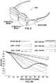
- FIGS 9A-9Dillustrate the polychromatic modulation transfer function (MTF) of 20 sampled fields across the field of view in the HMD path with a 4-mm centered pupil.
- the MTF curvesdemonstrate an average contrast of 0.2 at the cutoff resolution of 50 lps/mm (equivalent to a 10 ⁇ m pixel resolution) and an average contrast greater than 0.3 at the cutoff resolution of 35 lps/mm (equivalent of approximately 15-um pixel resolution).
- Figure 10further demonstrates the distortion grid of the virtual display path.
- one or more NIR LEDs 530are placed around the image source to create a uniformly illuminated eye area through the freeform prism 510.
- the freeform prism 510is able to provide uniform illumination for an eye area of approximately 30 mm x 20 mm in the horizontal and vertical directions, respectively.
- the same illuminated eye areais captured by a high resolution NIR sensor 560.
- the imaged areais sufficient to allow eye movement tracking.
- the resolvable pixel size of the eye imaging pathis about ⁇ 10um.
- Figure 11illustrates the modulation transfer function (MTF) of the eye imaging path.
- MTFmodulation transfer function
- the MTF curvesdemonstrate an average contrast of 0.1 at the cutoff resolution of 50 lps/mm (equivalent to a 10 ⁇ m pixel resolution) and an average contrast greater than 0.25 at the cutoff resolution of 30 lps/mm (equivalent of approximately 16-um pixel resolution).
- Figure 12further illustrates the distortion grid of the eye imaging path.
- the cemented prism 510 and freeform corrective lens 515provide a diagonal FOV of approximately 100 degrees, or 80 degrees horizontally and 50 degrees vertically.
- the see-through FOVis designed to be much larger than the virtual display FOV for improved situational awareness.
- the eyebox size of the see-through systemis optimized to be larger than the virtual display system to further improve ease of use and viewing comfort.
- This design embodimentachieves high image contrast and resolution.
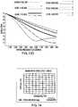
- Figures 13A-13Dillustrate the polychromatic modulation transfer function (MTF) of 20 sampled fields across the center 30x22 degrees of field of view in see-through path with a 4-mm centered pupil. The MTF curves demonstrate nearly diffraction limited performance. In Figs.
- MTFpolychromatic modulation transfer function
- 0.5 cycles/mincorresponds to 1 minute of arc spatial resolution, which is the resolvability of 20/20 vision
- 1 cycles/mincorresponds to 0.5 minute of arc spatial resolution, which is the resolvability of 20/15 vision.
- the average MTF across the sampled fieldsis greater than 0.5 at the cutoff resolution of 0.5 cycles/min (equivalent to 1 minute of arc angular resolution) and an average contrast greater than 0.4 at the cutoff resolution of 1 cycles/min (equivalent to 0.5 minutes of arc angular resolution).
- the average MTF across the entire 80x50 see-through FOVis greater than 0.35 at the cutoff frequency of 0.5 cycles/min.
- Figure 14further illustrates the distortion grid of the see-through display path across the entire FOV. The distortion in the central 40x22 degrees is less than 2% and the distortion across the whole field is less than 8%.
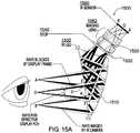
- FIGS 15A-15Bschematically illustrate an exemplary design of a second configuration of the present invention, where the stop 1540 of the imaging system 1500 may surround the microdisplay 1520.
- the microdisplay planeis divided into three regions: an IR-transmissive area 1527 that allows collecting the rays by an IR sensor 1560 and which may serve as the stop 1540 for eye imaging on IR sensor 1560; the active area of the microdisplay 1520 (non-transmissive) corresponding to the active display area which blocks the IR rays from reaching the IR sensor 1560; and, a third non-transmissive frame 1523 between the IR transmissive and microdisplay areas corresponding to a physical frame of the microdisplay which also blocks the rays from reaching the IR sensor 1560.
- the respective optical axes of the prism 1510, microdisplay 1520, and IR sensor 1560may be coaxial.
- the IR sensor 1560may be placed after the microdisplay 1520 to capture the image of the eye pupil.
- the distance from the IR sensor 1560 to the prism 1510depends on the image location of the eye pupil through the freeform prism 1510, which ultimately depends on the design of the display path. For instance, if the freeform prism 1510 is designed to be telecentric or close to telecentric in the display space, the chief rays will be nearly parallel to each other and perpendicular to the microdisplay surface before they intersect with the microdisplay 1520.
- the image of the eye pupil through the prism 1510is located at infinity or a significantly far distance.
- one or more additional imaging lenses 1562may need to be inserted between the IR sensor 1560 and the prism 1510 to reduce the overall length of the eye imaging path and achieve good image quality, Fig. 15A .
- the freeform prism 1510is designed to be non-telecentric (i.e ., the chief rays will converge to a point at some short distance behind the prism 1510), the eye pupil is imaged at a fairly close distance by the prism 1510 and the IR sensor 1560 can be placed directly behind the prism 1510 without the need for additional imaging lenses 1562.
- the condition of telecentricity or near-telecentricityis often desirable when designing the display path because the virtual image appears to be more uniform across the entire FOV. This condition may be required when the microdisplay 1520 only emits or reflects light within a narrow angle (e.g. devices such as LCoS type microdisplays). When the microdisplay 1520 offers a wide emission angle (e.g. OLED), the telecentricity condition can be relaxed.
- the NIR LEDsmay be placed around the stop 1540 in the similar way as described in Fig. 3B , or alternatively the NIR LEDs 1530 may be placed around the edge of the prism 1510 and directly illuminate the eye 10 as shown in Fig. 15A . Moreover, the NIR LEDs 1530 around the edge of the prism 1510 to directly illuminate the eye 10 without use of the prism 1530 may be implemented in any other configuration of the invention, including those depicted in Figs. 5A-6 or 16 , for example.
- Figure 16schematically illustrates an exemplary design 1600 of the optical scheme shown in Fig. 3 utilizing on rotationally symmetric optics for the core optics 310.
- a four-element viewing optics 1610is used as the core optics 310 for display viewing, eye imaging and eye illumination.
- the microdisplay 1620may be placed at the focal plane of the optics 1610.
- One light source 1630(such as an NIR-LED) may be placed around the image source 1620.
- a pinhole-like stop 1640 and micro-imaging lens 1662may also be placed around the edge of the image source 1620 to form eye images on the imaging sensor 1660.
- Additional light sources 1630 and imaging subsystemscan be arranged around the image source 1620 as needed for different applications.
- the respective optical axes of the display optics 1610 and microdisplay 1620maybe coaxial, while the respective optical axes of one or more of the image sensor 1660, light source 1630, and microdisplay 1620 may be tilted and/or decentered relative to one another.
- the illumination path, eye imaging path, and display pathimpinge upon differing respective portions of surface 8, though partial overlap is permitted, e.g., as illustrated between the imaging path and display path.
- the viewing optics 1610can provide a diagonal FOV of 40 degrees, 20-mm eye-relief and 10-mm eye-pupil size, and can support an image source 1620 with a diagonal size of 0.8" or smaller.
- One or more NIR LEDs 1630may be placed around the microdisplay 1620 to create a uniformly illuminated eye area through the viewing optics.
- the viewing optics 1610is able to provide uniform illumination for an eye area of approximately 15mm x 15mm.
- the same illuminated eye areamay be captured by a high resolution NIR sensor 1630.
- the imaged areais sufficient to allow eye movement tracking.
- Table 6Optical surface prescription of the viewing optics 1610 SURFACE NUMBER SURFACE TYPE RADIUS (MM) THICKNESS (MM) MATERIAL OBJECT INFINITY INFINITY AIR 1 (STOP) 0 20 AIR 2 SPHERE 38.747568 13 ACRYLIC 3 SPHERE -68.038477 2.940552 AIR 4 SPHERE 87.660626 4.795025 ACRYLIC 5 SPHERE -52.591345 0.1 AIR 6 SPHERE 29.845125 10.782261 NBK7 7 SPHERE -23.016798 8 SF61 8 SPHERE 30.000017 7.076910 AIR 9 (MICRODISPLAY) INFINITY 0
- Table 7Optical surface prescription of the imaging lens 1662 SURFACE NUMBER SURFACE TYPE RADIUS (MM) THICKNESS (MM) MATERIAL 10 (STOP)
- Table 8Optical surface prescription of surface 11 of the imaging lens Y Radius 41.495014 Conic Constant (K) -20 4th Order Coefficient (A) -1.021763E-02 6th Order Coefficient (B) -6.885433E-04 8th Order Coefficient (C) -3.263238E-04 10th Order Coefficient (D) 0
- Table 9Optical surface prescription of surface 12 of the imaging lens Y Radius -2.858167 Conic Constant (K) -1.750218 4th Order Coefficient (A) -7.851177E-03 6th Order Coefficient (B) -1.064232E-04 8th Order Coefficient (C) -4.912295E-05 10th Order Coefficient (D) 0
Landscapes
- Physics & Mathematics (AREA)
- General Physics & Mathematics (AREA)
- Optics & Photonics (AREA)
- Engineering & Computer Science (AREA)
- General Engineering & Computer Science (AREA)
- Theoretical Computer Science (AREA)
- Spectroscopy & Molecular Physics (AREA)
- Human Computer Interaction (AREA)
- Lenses (AREA)
- Eyeglasses (AREA)
- Eye Examination Apparatus (AREA)
Description
- The present invention relates generally to eye-tracked head-mounted displays, and more particularly, but not exclusively, to eye-tracked head-mounted displays which may utilize the same optics for eyetracking and image viewing, with a selected portion of the optics used for an eyetracking optical path and a selected portion of the display optics used for an image viewing optical path.
- Head-mounted display (HMD) technologies have been applied to a wide range of scientific and engineering domains. Examples of applications include flight simulation, scientific visualization, medicine, engineering design, education and training, wearable computing, and entertainment systems. In the domain of augmented reality, HMDs are one of the enabling technologies for merging virtual views with physical scenes, which may enable a physician to see a 3D rendering of the anatomical structures or CT images of a patient superimposed onto the patient's anatomy, such as the abdomen, for example. In the domain of wearable computing, an HMD creates a mobile display solution that offers much more attractive image quality and screen size than other popular mobile platforms such as smart phones and PDAs. In the foreseeable future, such mobile displays may appear as elegant as a pair of sunglasses and may become an integral part of many people's daily activities to retrieve information and connect with people instantly.
- In parallel with HMD technologies, various eyetracking technologies have been developed and applied to several disciplines including vision research, human computer interfaces, tele-operation environments, and visual communication. The benefits of eyetracking for multi-modal human-computer interfaces and the technical benefits of data compression have been well-recognized and studied. For instance, multi-resolution gaze-contingent display and image processing schemes have been proposed to effectively save data transmission bandwidth in communication, and improve rendering speed of 3D scenes using foveated level-of-detail management methods, and to achieve wide FOV high-resolution display and imaging systems.
- The concept of creating an integrated eyetracked HMD (ET-HMD) system has been explored in various levels. An ET-HMD is able to display monocular or stereoscopic virtual images as a classical HMD does, while additionally tracking the gaze direction of the user. A fully-integrated ET-HMD offers multi-fold benefits, not only to fundamental scientific research but also to emerging applications of such technology. For instance, many research efforts are concerned about how human users perceive and organize spatial information, interact with such information, and navigate within 3D virtual spaces. Eyetracking capability in HMDs adds a very valuable tool and objective metric for scientists to quantitatively assess user interaction with 3D environments and investigate the effectiveness of various 3D visualization technologies for various specific tasks including training, education, and augmented cognition tasks. From the technology point of view, eyetracking capability integrated with HMD systems can be utilized to improve size and depth perception accuracy in stereoscopic displays. Eyetracking capability may help to create solutions to the FOV-resolution tradeoff through a fovea-contingent display scheme and to the accommodation-convergence contradiction by using vari-focal plane display methodology. From the application point of view, an ET-HMD offers unique opportunities for novel interactive interfaces for people with proprioceptive disabilities where eye gaze instead of hands or feet can be used as a method of interaction and communication.
- Despite significant advancements and commercial availability of stand-alone HMD and eyetracking technologies, integrating these two stand-alone technologies imposes significant challenges in creating a compact, portable, accurate and robust system. Although several pioneering efforts were made to develop ET-HMD technologies and to optimize these two technologies in a systematic approach, none of the existing technological solutions offers a truly portable, lightweight, and robust system that conforms to the form factor of an eyeglass-style display. For many demanding applications, lightweight and compactness are critical. For instance, to support Amyotrophic Lateral Sclerosis (ALS) patient communication, the integrated system has to be lightweight so that the patients are able to bear the weight with their significantly weakened muscles and very limited mobility.
- Over the past decades, many different optical design approaches have been applied to HMD designs to improve the system performance. These methods include applying catadioptric technique, introducing new elements such as aspherical surfaces, using holographic and diffractive optical components, exploring new design principles such as using projection optics to replace an eyepiece or microscope type lens system in a conventional HMD design, and introducing tilt and decenter or even freeform surfaces. Few of these optical design methods are capable of creating a wide field-of-view, compact, and lightweight HMD that is nonintrusive and can be considered as being eyeglass-style near-eye displays. Integrating eyetracking capability to these technologies is very challenging and adds significant weight, volume, and complexity.
- Adding eyetracking capability to HMDs started as early as the high resolution inset displays by CAE Corporation. This pioneering work was not intended for mobile compact ET-HMD systems. Also, others used a mechanical driving device to move a high resolution inset in a bench-prototype stereoscopic display. ISCAN Corporation worked to integrate an ISCAN eyetracker into a V8-HMD from Virtual Research Corporation to study software-based fovea-contingent display scheme. This method of integrating commercially available HMDs and eye-trackers is referred to as the functionality integration approach, in which two separate instruments are brought together at a later stage of utilization. Though the functionality integration approach has the advantage of being a simple solution with low development cost, it generally does not take advantage of low-level optimization and lacks the attributes of compactness, accuracy, and robustness.
- In contrast to the functionality integration approach, a systematic approach, where the system is conceived and optimized as one single instrument from a fundamental design perspective, has many advantages in creating a fully integrated ET-HMD instrument. The significant benefits of the systematic approach include the ability to explore the design constraints and requirements for both the display and eyetracker units, conceive new solutions, and optimize the designs for a compact and robust system. Pioneering efforts have been made to explore the possibility of a complete integration with low-level optimization. Following these earlier efforts, Hua and Rolland collaboratively pursued a fully integrated design approach, developed robust eyetracking methods and algorithms for an ET-HMD system, and designed an optical see-through ET-HMD optical system based on the concept of head-mounted projection displays.
Figure 1 shows the first-order layout of the ET-HMD optical system, in which the optical system was simplified with ideal lens modules to emphasize the concept and the scale. (Curatu, C., Hong Hua, and J. P. Rolland, "Projection-based head-mounted display with eye-tracking capabilities," Proceedings of the SPIE International Society for Optical Engineering, Vol. 5875, San Diego, USA, August 2005.Curatu, C., J.P. Rolland, and Hong Hua, "Dual purpose lens for an eye-tracked projection head-mounted display," Proceedings of International Optical Design Conference, Vancouver, Canada, June 2006.). The design took a full integration approach and combined most of the optical paths for the display and eyetracking subsystems. The same projection optics was shared for both display and eye imaging functions. The main limitation of this design, however, was that the overall volume of the integrated ET-HMD system, although significantly improved over others, was still bulky and heavy. - A head-mounted display involving an eye-tracking system is disclosed in
US 2001/009478 A1 . - The key challenges of creating a truly portable, lightweight, compact ET-HMD solution lies in addressing two cornerstone issues: (1) an optical method that enables the design of an HMD system with an elegant form factor as compelling as a pair of sunglasses, which has been a persistent dream for both technology and application developers; and (2) an optical method that allows the integration of the eyetracking capability without adding significant weight and volume to the system.
- An ET-HMD system using a video-based feature tracking method typically requires at least three unique optical paths: an illumination path, an eye imaging path, and a virtual display path. Through the illumination path the eye is illuminated by typically near infrared light-emitting diodes (NIR LEDs) to create imaging features such as darkened or brightened pupil and/or Purkinje features for tracking. Through the imaging path, an eye image with the tracking features is captured for feature detection and tracking. Through the display path, a virtual image displayed on a miniature display device is created through eyepiece optics for information viewing. One of the innovations of the present invention is an optical scheme that can uniquely combine these three optical paths through the same core optics, which may be an eyepiece, projection lens, or other optics structure.
- For example, in one of its aspects, the present invention may use freeform optical technology along with an innovative optical scheme that can uniquely combine eye imaging optics for eyetracking with the display optics for information viewing. (Thus, as used herein in connection with description of the present invention, the terms "display optics" and "imaging optics" may refer to the same physical optics, which physical optics may also be called the "core optics".) Optionally, the eye illumination optics may also be combined. As such, in one of its advantages the present invention avoids the limitation imposed by prior approaches where the optical systems for the HMD and eyetracking paths are treated separately, and where rotationally symmetric optical surfaces are mostly used. However, though possibly more limiting, the optical scheme of integrating eyetracking with HMD disclosed in the present invention is not limited to freeform optics. The core optics for the ET-HMD system in accordance with the present invention can be applied to conventional HMD optics.
- The eye-tracked head mounted display according to the invention is disclosed in
claim 1. In addition, the eye-tracked head-mounted display may include a stop at the first plane, where the stop has at least one aperture therein disposed at a location along the sensor optical path. Likewise, the eye-tracked head-mounted display may include a stop having at least one aperture therein disposed at a location along the sensor optical path between the sensor and selected surface. In either configuration, the stop or aperture may include a pin-hole like aperture. In one exemplary configuration, the display optics may include a freeform optical element, a rotationally symmetric optical element, and/or a freeform optical prism. The display optics may include an aspheric surface. - In addition, the eye-tracked head-mounted display may include an illumination source for generating optical radiation to illuminate the second plane to effect illumination of the user's eye. The display optics may be configured to collimate the optical radiation from the illumination source. The illumination source may be located in the first plane or at a different location, such as off axis from the optical axis of the display optics.
- The foregoing summary and the following detailed description of exemplary embodiments of the present invention may be further understood when read in conjunction with the appended drawings, in which:
Figure 1 schematically illustrates a conventional eyetracked head-mounted display (ET-HMD) system based on rotationally symmetric optical technology;Figures 2A, 2B schematically illustrate images from two different IR illumination strategies, withFig. 2A showing an eye image of a bright eye pupil and four glints resulting from an on-axis illumination strategy where four NIR LEDs are arranged nearly co-axially with the optical axis of the eye imaging optics, andFig. 2B showing an eye image of a dark eye pupil and four glints resulting from an off-axis illumination strategy where the four NIR LEDs are placed away from the optical axis of the eye imaging optics;Figure 3A schematically illustrates an exemplary optical system in accordance with the present invention shown as a monocular optical module;Figure 3B schematically illustrates an exemplary system in accordance with the present invention of illumination units and eye imaging units disposed around a microdisplay panel;Figure 4 schematically illustrates a block diagram of an exemplary system based on freeform prism technology in accordance with the present invention shown as a monocular optical module;Figures 5A - 5D schematically illustrate an exemplary design of an optical see-through HMD in accordance with the present invention, withFig. 5A showing the eye illumination and imaging paths,Fig. 5B showing the virtual display path,Fig. 5C showing a freeform prism shared by eye illumination, eye imaging, and virtual display paths, andFig 5D showing a freeform auxiliary lens attached to the freeform prism, which enables see-through capability;Figure 6 schematically illustrates an optical layout and raytracing of an exemplary optimized ET-HMD system in accordance with the present invention using the 2-reflection freeform prism structure ofFig. 5D ;Figure 7 schematically illustrates a 3D model of an exemplary ET-HMD optical system in accordance with the present invention;Figure 8 schematically illustrates a model of an exemplary binocular ET-HMD prototype in accordance with the present invention based on the optical design inFigs. 6 and 7 ;Figures 9A-9D illustrate the polychromatic modulation transfer function (MTF) of 20 sampled fields across the field of view in the HMD virtual display path with a 4-mm centered pupil of the design ofFig. 6 ;Figure 10 illustrates the distortion grid across the field of view in the HMD virtual display path of the design ofFig. 6 ;Figure 11 illustrates the modulation transfer function of sampled fields across the field of view in the eye imaging path of the design ofFig. 6 ;Figure 12 illustrates the distortion grid across the field of view in the eye imaging path of the design ofFig. 6 ;Figures 13A-13D illustrate the polychromatic modulation transfer function (MTF) of 20 sampled fields across the central field of view of 30x22 degrees in the HMD see-through path with a 4-mm centered pupil of the design ofFig. 6 ;Figure 14 illustrates the distortion grid across the field of view in the HMD see-through path of the design ofFig. 6 ;Figures 15A ,15B illustrate an exemplary design of the optical scheme shown inFig. 3 in accordance with the present invention; andFigure 16 schematically illustrates an exemplary implementation of the optical scheme shown inFig. 3 in accordance with the present invention based on rotationally symmetric optics.- Referring now to the figures, wherein like elements are numbered alike throughout,
Figure 3A schematically illustrates anexemplary system layout 300 in accordance with the present invention for achieving a compact ET-HMD system. In thisexemplary layout 300, thesame core optics 310 may serve the functions of eye imaging, display viewing, and/or eye illumination. This simplification stems from an insightful observation on the unique conjugate planes in theeye illumination path 305,eye imaging path 307, anddisplay path 309. In addition, differing portions along the clear aperture of thecore optics 310 may be used for theeye illumination path 305,eye imaging path 307, anddisplay path 309. For instance, at a selected surface of thecore optics 310 located closest to the micro-display, two or more of theeye illumination path 305,eye imaging path 307, and display path 309 (e.g.eye imaging path 307 and display path 309) can impinge upon differing respective portions of the selected surface, though partial overlap is permitted. - In the
display path 309, thecore optics 310, which in this context functions as display optics, forms a magnified virtual image of themicrodisplay 320 seen by theeye 10. Themicrodisplay unit 320 can be any type of self-emissive, or illuminated pixel arrays that can serve as an image source, including, but not limited to, a liquid crystal on silicon (LCoS) display device, a liquid crystal display (LCD) panel, an organic light emitting display (OLED), ferroelectric liquid crystal on silicon (FLCoS) device, digital mirror device (DMD), or a micro-projector built upon these aforementioned or other types of micro-display devices, and additional optional optics may be provided between themicrodisplay 320 andcore optics 310, as desired or required. The magnified virtual image, which may appear to be at an infinite or finite distance from theeye 10, corresponds to the conjugate focal plane of themicrodisplay 320. Theeye pupil 12 may be co-located with theexit pupil 312 of thedisplay path 309. The chief rays of the display through the center of the pupil 12 (shown in solid lines inFig. 3A ) define the field height on themicrodisplay 320, and thus they are separable on the microdisplay surface. In theeye illumination path 305, one or multiple NIR LEDs (near-infrared light-emitting diodes) 330 may be mounted around themicrodisplay 320 to illuminate the eye through the display/core optics 310,Fig. 3B . The display/core optics 310 may collimate the LED light and create a uniformly illuminated area on the eye area through multiple virtual LED sources created through the display/core optics 310. Such an off-axis illumination arrangement can create a dark-pupil effect and form multiple glint images of theNIR LEDs 330 through the reflection off the anterior cornea. - In the
eye imaging path 307, theeye pupil 12 becomes the object that needs to be imaged. Astop 340 may be placed around themicrodisplay 320. Considering the pupil-field relationship of themicrodisplay 320 and theeye pupil 12 described earlier, the chief rays of different object fields in the display path become the marginal rays of the on-axis object point in theeye imaging path 307, and thus all the rays through the same point on theeye pupil 12 will be imaged onto the same point on theIR imaging sensor 360. These rays, however, intersect with the microdisplay surface at unique locations. Therefore, in theimaging path 307, astop 340 is properly designed and placed around themicrodisplay 320 such that it does not affect thedisplay path 309 and yet is sufficient to collect rays to form eye images in theeye imaging path 307. In the illustration shown inFigure 3B , thestop 340 may be provided in the form of pin-hole likesmall apertures 350 or may be a selected area surrounding themicrodisplay 320. Aseparate image sensor 360 may be associated with each pin-hole likeaperture 350. - As one of its benefits, the
optical layout 300 for combining two or three unique optical functions has applicability to virtually all types of optical structures suitable for HMD optics. For instance, an exemplary configuration with a conventional eyepiece optics based on rotationally symmetric optical elements has been designed, as discussed below in connection withFig. 16 . - As to the eyetracking function aspect specifically, several different eyetracking techniques exist that may be used to monitor eye movements, which fall into three categories: electro-oclography, scleral search coil, and various video-based feature tracking approaches. Among these methods, video-based feature tracking, which detects and tracks features in captured eye images, can be the least intrusive and most convenient approach to track eye movement.
- Under near infrared NIR illumination, the
eye images Figs. 2A, 2B . One feature is known as the first Purkinje image, orglint 6, which refers to the reflection image of a point light source formed by the anterior surface of the cornea,Fig. 2B . The second feature is theeye pupil 12.Figures 2A-2B demonstrate examples of IR-illuminatedeye images NIR LEDs 330, an on-axis illumination strategy where the IR illuminators are arranged nearly co-axial with the optical axis of the eye imaging optics leads to abright pupil 2,Fig. 2A , while an off-axis illumination strategy where the IR illuminators are placed away from the optical axis of the eye imaging optics leads to adarkened pupil 4 with glint(s) 6,Fig. 2B . The pupil and glint features may then be utilized for eye movement tracking. - Among the video-based feature tracking methods, the pupil-corneal reflection tracking method, which relates the eye movements with the vector difference between the pupil center and the glint center, may be a most suitable approach in an ET-HMD system. In this method, one or multiple NIR light emitting diodes (NIR LED),e.g.,
NIR LEDs 330, may be used to illuminate theeye 10, and theilluminated eye 10 may then imaged by theimaging sensor 360, such as an infrared CCD. Theeye pupil 12, the first Purkinje image (or glint), and/or theiris 11 may be tracked simultaneously or separately. EachNIR LED 330 may form aglint 6 or a first Purkinje image. Thepupil 12 and first Purkinje features move proportionally with eye rotation and differentially between each other. The differential vector between the two features may be used to determine the point-of-regard of theeye 10. To some extent this method can tolerate helmet slippage in a HMD system, which causes orientation change of theimaging sensor 360 relative to theeye 10 and confuses the eye movements. - In another of its significant aspects, the present invention may utilize freeform optical technology in the
core optics 310 to achieve an ultra-compact and lightweight ET-HMD with see-through capability.Figure 4 shows a block diagram 400 of an exemplary approach to a compact eyetracked HMD design in accordance with the present invention based on freeform optical technology. In one exemplary implementation, a wedge-shapedfreeform prism 410 or waveguide-type freeform prism may be used in thecore optics 310, which allows the ray paths to be folded within a multi-surface prism structure and helps reduce the overall volume and weight of the display optics when compared with designs using rotationally symmetric elements. Applying freeform optical technology enables full integration of the functions of HMD optics and eyetracking into a compact form. Thefreeform prism 410 may be made of moldable plastic for lightweight and low cost. - In this approach, the
freeform prism 410 may serve two or more unique optical functions. First, thefreeform prism 410 may serve as the core element in theeye imaging path 407 that captures NIR-illuminatedeye images 401 of a user and tracks eye movements using the capturedeye images 401. Unlike a conventional imaging system, which typically employs rotationally symmetrical optical surfaces in the lens construction and typically requires the imaging lenses remain collinear with thedetector 460 and the objects to be captured, thefreeform prism 410 folds the light path within a single element so that theimage detector 460 may be placed on the side of thefreeform prism 410. Second, the samefreeform prism 410 may serve as display viewing optics for viewing images on themicrodisplay 420 in thedisplay path 409. Third, theprism 410 may serve as the core element in theillumination path 305 that collimates the light from one or multiple of theNIR LEDs 430. Alternatively, the NIR LEDs may illuminate the eye area directly without passing through the prism 410 (or core optics 310). In either case, theNIR LEDs 430 may uniformly and non-invasively illuminate the eye area and form critical features (e.g. glints 6 and darkened pupil 4) that are to be imaged for eyetracking. Finally, if an optical see-through ET-HMD system is required for applications where a direct view of the real world is critical, theprism 410 may be cemented with a freeformcorrective lens 415. Thefreeform corrector 415 can correct the viewing axis deviation and undesirable aberrations introduced by theprism 410 and enables see-through capability of thesystem 400 which offers low peripheral obscurations and minimized distortions to the real-world view 411. Overall, the unique optical scheme of the present invention can enable the combination of the optical paths for theeye imaging 407 and thevirtual display 409, andoptionally eye illumination 405, through the samefreeform prism 410 and can achieve the capabilities of eyetracking and display with minimum hardware cost. - A first
exemplary configuration 500 in accordance with the present invention utilizes wedge-shapedfreeform prism 510 with two reflections,Figs. 5A-5D . In this embodiment, thefreeform prism 510 may serve as many as three core functions: (1) as an illumination optic that collimates the light from one ormultiple NIR LEDs 530 to uniformly and non-invasively illuminate the eye area to be imaged; (2) as the core element of an eye imaging optic that captures NIR-illuminated eye images to enable eye movement tracking; and (3) as an eyepiece optic of an HMD system to view images on amicrodisplay 520. These three unique optical paths may be combined by the samefreeform prism 510 to achieve the capabilities of eyetracking and display. Additionally, thesame prism 510 when cemented with a freeform corrective lens enables the see-through capability of an optical see-through HMD system. Alternatively,freeform prism 510 may omit the core function as an illumination optic. - The wedge-shaped
freeform prism 510 may include three optical surfaces, at least of one of which may be an aspheric surface with or without rotational symmetry. One innovation of the present invention is the optical approach that can uniquely combine the two or three unique optical paths (i.e., two or more of theeye illumination path 505,eye imaging path 507, and display path 509) via the singlefreeform prism 510.Figure 5A shows the schematic design of the eye illumination and imaging optics, which includesfreeform prism 510. In theillumination path 505, a ray emitted from anNIR LED 530 is first refracted by thesurface 3, followed by two consecutive reflections by thesurfaces 1' and 2, and finally is transmitted through thesurface 1 and reaches theeye 10. The reflection on surface 1' may satisfy the condition of total internal reflection (TIR). The light emitted by theLEDs 530 may be collimated by theprism 510, yielding a uniform illumination to theeye 10. The NIR illuminatedeye 10 may then be imaged by anIR image sensor 560. In theeye imaging path 507, light rays scattered off theeye 10 may be first refracted by thesurface 1, followed by two consecutive reflections by thesurface 2 and 1', and finally may be transmitted through thesurface 3 and reach thesensor 560.Additional lenses 562 may be inserted between thesurface 3 of theprism 510 and theimage sensor 560 to improve optical performance of the eye imaging. A small-aperture stop 550 may be placed near or inside thelenses 562 to confine the light received by theimaging sensor 560. Figure 5B schematically illustrates thedisplay path 509 of HMD optics using thefreeform prism 510 to magnify the image on amicrodisplay 520, forming a virtual image at a comfortable viewing distance. A ray emitted from a point on themicrodisplay 520 may be first refracted by thesurface 3 of thefreeform prism 510, followed by two consecutive reflections by thesurfaces 1' and 2, and finally may be transmitted through thesurface 1 to reach theexit pupil 512 of thesystem 500. The reflection on surface 1' may satisfy the TIR condition. Rather than requiring multiple elements, the optical path is naturally folded within the prism structure. Additional lenses may be inserted between thesurface 3 of theprism 510 and themicrodisplay 520 to further improve optical performance of thedisplay path 509.Figure 5C schematically illustrates theintegrated system 500 where the illumination, imaging and display optics comprise thesame prism 510 and theillumination LEDs 530 and a pinhole-like stop 550 are placed around theedge 540 of themicrodisplay 520 to form a high-quality eye image. One example of the stop and LED configurations is illustrated inFigure 5C . It is worth noting thestop 550 andLEDs 530 may be placed in other locations at the periphery around in themicrodisplay 520. In addition, thestop 550 andLEDs 530 may or may not be coplanar with themicrodisplay 520. Additional lenses may be used in one or more of theillumination path 505,eye imaging path 507, anddisplay path 509 to improve the system performance. Moreover, at the surface closest to themicrodisplay 520,surface 3, theillumination path 505,eye imaging path 507, anddisplay path 509 may impinge upon differing respective portions of surface 3 (though partial overlap is permitted).- To enable see-through capability, the
surface 2 of theprism 510 may be coated as a half mirror. The rays from themicrodisplay 520 may be reflected by thesurface 2 while the rays from a real-world scene are transmitted.Figure 5D schematically illustrates a freeformauxiliary lens 515, consisting of twofreeform surfaces prism 510 to correct the viewing axis deviation and aberrations introduced by thefreeform prism 510 to the realworld view path 511. Thesurface 4 of theauxiliary lens 515 usually has the same prescription as thesurface 2 of theprism 510 and thesurface 5 of theauxiliary lens 515 is optimized to correct the axis deviation and the aberrations. Theauxiliary lens 515 does not noticeably increase the footprint or weight of the overall system. Overall, theexemplary system 500 provides a lightweight, compact, robust, and eyetracked HMD solution with a less obtrusive form factor than any existing HMD approaches can potentially deliver, which is further demonstrated by computer analysis of the design. Figure 6 schematically illustrates the two-dimensional optical layout of an optimized system based on the 2-reflection wedge-shapedfreeform prism 510 depicted inFigure 5 . In this implementation, animaging lens 562 may be used to improve the performance of theeye imaging path 507. Thestop 550 may be positioned close to thesurface 3 of theprism 510. The NIR-LED(s) 530 may be positioned around themicrodisplay 520.Figure 7 schematically illustrates a3D model 700 of the exemplary optical system ofFig. 5D , andFigure 8 schematically illustrates the 3D model of a binocular ET-HMD prototype 800 based on the optical design shown inFigs. 6 and 7 . The specifications of the overall system are listed in Table 1.Table 1: Optical System Specifications Parameter Values Virtual display system Display FOV 46° (Diagonal), 40° (Horizontal) x 22° (Vertical) Exit pupil diameter 10 mm (zero vignette), offer an eyebox of 18mm for a 4mm pupil. Eye clearance 19 mm Display resolution 1920x1200 color pixels Distortion < 8% across FOV Image quality (MTF) Average 20% at 50 lps/mm and average 30% at 35lps/mm Design wavelength 450 - 650 nm See-through viewing optics See-through FOV Approximately 100° (Diagonal), 80° (Horizontal) x 50° (Vertical) Distortion < 10% at the edge and less than 2% at the center Image quality (MTF) > 50% at 0.5 cycles/min and greater than 0.3 at 1 cycles/min Design wavelength 450 - 650 nm Eye tracking sub-system FOV (Imaged eye area) 30 mm (H) x 20 mm (V) Image quality (MTF) Average 10% at 50 lps/mm and average 25% at 30lps/mm Distortion <5% across the imaged area Design wavelength 750-900 nm - An exemplary optical prescription of the
freeform prism 510 is listed in the Tables 2-4 forsurfaces prism 510, thesurface 1 is an anamorphic aspheric surface (AAS). The sag of an AAS surface is defined by
Surface 2 of theprism 510 may be an XY polynomial surface defined by:
Surface 3 may be an aspheric surface with a rotationally symmetric kinoform diffractive optical element, with the sag of the aspheric surface defined by:
Table 2: Optical surface prescription of surface 1 of the freeform prism X Curvature (cx) -1.348215E-02 Y Curvature (cy) 2.004523E-03 Y Conic Constant (KY) 0.998125E+01 4th Order Symmetric Coefficient (AR) -3.9067945E-06 6th Order Symmetric Coefficient (BR) -9.5768964E-17 8th Order Symmetric Coefficient (CR) -2.8799927E-15 10th Order Symmetric Coefficient (DR) -8.7077963E-16 X Conic Constant (KX) -1.5687534E+01 4th Order Asymmetric Coefficient (AP) -3.2949463E-01 6th Order Asymmetric Coefficient (BP) -2.0405356E+02 8th Order Asymmetric Coefficient (CP) -8.0782710E+00 10th Order Asymmetric Coefficient (DP) -2.72019184E-01 

Table 4: Optical surface prescription of surface 3 of the freeform prism 510 Y Radius -1.5000000000E+01 Conic Constant (K) -8.1715030467E+00 4th Order Coefficient (A) -3.5999478362E-05 6th Order Coefficient (B) 4.1811989405E-07 8th Order Coefficient (C) -2.0382499300E-09 10th Order Coefficient (D) 3.7498678418E-12 Diffraction Order 1 Construction Wavelength (nm) 550 R**2 (HCO C1) -3.2332326174E-03 R**4 (HCO C2) 4.1482610496E-05 R**6 (HCO C3) -4.2185152895E-07 R**8 (HCO C4) 1.8253428127E-09 R**10 (HCO C5) -2.7615741244E-12 - An exemplary optical prescription of
surface 5 of thefreeform corrector 515 lens is listed in Table 5.Surface 4 of thelens 515 has the same prescription as thesurface 2 of theprism 510 and thesurface 5 of thelens 515 is an XY polynomial surface defined by the same equation as forsurface 2.Table 5: Optical surface prescription of surface 5 of the freeform corrector lens Y Curvature -4.9680519947E-03 Y Radius -2.0836485397E+02 Conic Constant (SCO K | C1) 9.64085149870E+00 X (SCO X | C2) 0.00000000000E+00 Y (SCO Y | C3) 0.00000000000E+00 X**2 (SCO X2 | C4) -3.7131327715E-03 X * Y (SCO XY | C5) 0.00000000000E+00 Y**2 (SCO Y2 | C6) 3.49505772747E-03 X**3 (SCO Y3 | C7) 0.00000000000E+00 X**2 * Y (SCO X2Y | C8) -1.5261510919E-07 X Y**2 (SCO XY2 | C9) 0.0000000000E+00 Y**3 (SCO Y3 | C10) -9.571153875E-08 X**4 (SCO X4 | C11) -1.871425121E-07 X**3 * Y (SCO X3Y | C12) 0.000000000E+00 X**2 * Y**2 (SCO X2Y2 | C13) -2.91567230E-06 X * Y**3 (SCO XY3 | C14) 0.000000000E+00 Y**4 (SCO Y4 | C15) -8.129645853E-07 X**5 (SCO X5 | C16) 0.0000000000E+00 X**4 * Y (SCO X4Y | C17) 1.4913830346E-09 X**3 * Y**2 (SCO X3Y2 | C18) 0.0000000000E+00 X**2 * Y**3 (SCO X2Y3 | C19) 2.4358316954E-09 X * Y**4 (SCO XY4 | C20) 0.0000000000E+00 Y**5 (SCO Y5 | C21) 4.1849942311E-09 X**6 (SCO X6 | C22) -9.610954967E-10 X**5 * Y (SCO X5Y | C23) 0.0000000000E+00 X**4 * Y**2 (SCO X4Y2 | C24) 5.6221328063E-10 X**3 * Y**3 (SCO X3Y3 | C25) 0.0000000000E+00 X**2 * Y**4 (SCO X2Y4 | C26) 7.656820595E-10 X * Y**5 (SCOXY5 | C27) 0.000000000E+00 Y**6 (SCO Y6 | C28) -2.99368733E-09 X**7 (SCO X7 | C29) 0.00000000E+00 X**6 * Y (SCO X6Y | C30) -4.2039898E-12 X**5 * Y**2 (SCO X5Y2 | C31) 0.0000000E+00 X**4 * Y**3 (SCOX4Y3 | C32) -7.665313E-12 X**3 * Y**4 (SCO X3Y4 | C33) 0.000000000E+00 X**2 * Y**5 (SCO S2Y5 | C34) -1.546473120E-11 X* Y**6 (SCO XY6 | C35) 0.000000000E+00 Y**7 (SCO Y7 | C36) -2.36018874E-11 X**8 (SCO X8 | C37) -1.08111832E-12 X**7 * Y (SCO X7Y | C38) 0.00000000E+00 X**6 * Y**2 (SCO X6Y2 | C39) -9.9791583E-13 X**5 * Y**3 (SCO X5Y3 | C40) 0.0000000E+00 X**4 * Y**4 (SCO X4Y4 | C41) -8.6526761E-12 X**3 * Y**5 (SCO X3Y5 | C42) 0.00000000E+00 X**2 * Y**6 (SCO X2Y6 | C43) -3.9166253E-12 X * Y**7 (SCO XY7 | C44) 0.00000000E+00 Y**8 (SCO Y8 | C45) 1.45724979E-11 X**9 (SCO X9 | C46) 0.00000000E+00 X**8 * Y (SCO X8Y | C47) 3.51280116E-15 X**7 * Y**2 (SCO X7Y2 | C48) 0.00000000E+00 X**6 * Y**3 (SCO X6Y3 | C49) 6.69288844E-15 X**5 * Y**4 (SCO XSY4 | C50) 0.00000000E+00 X**4 * Y**5 (SCO X4Y5 | C51) 6.15758388E-14 X**3 * Y**6 (SCO X3Y6 | C52) 0.00000000E+00 X**2 * Y**7 (SCO X2Y7 | C53) 1.94985620E-14 X * Y**8 (SCO XY8 | C54) 0.00000000E+00 Y**9 (SCO Y9 | C55) 4.24428256E-14 X**10 (SCO X10 | C56) 9.43112860E-16 X**9 * Y (SCO X9Y | C57) 0.000000000E+00 X**8 * Y**2 (SCO X8Y2 | C58) 2.10137145E-15 X**7 * Y**3 (SCO X7Y3 | C59) 0.00000000E+00 X**6 * Y**4 (SCO X6Y4 | C60) 1.130922231E-14 X**5 * Y**5 (SCO X5Y5 | C61) 0.000000000E+00 X**4 * Y**6 (SCO X4Y6 | C62) -1.93900784E-15 X**3 * Y**7 (SCO X3Y7 | C63) 0.000000000E+00 X**2 * Y**8 (SCO X2Y8 | C64) 7.080929646E-15 X * Y**9 (SCO XY9 | C65) 0.000000000E+00 Y**10 (SCO Y10 | C66) -1.96970504E-14 - On the display side of the exemplary design, the
prism 510 provides a diagonal FOV of 46 degrees, or 40 degrees horizontally and 22 degrees vertically. It supports amicrodisplay 520 with a pixel size of ∼8µm and a diagonal size of 0.9" or smaller. In the prototype that was fabricated, a 0.86" microdisplay with an aspect ratio of 16:9 and a resolution of 1920x1200 pixels was used. - The exemplary design achieves high image contrast and resolution.
Figures 9A-9D illustrate the polychromatic modulation transfer function (MTF) of 20 sampled fields across the field of view in the HMD path with a 4-mm centered pupil. The MTF curves demonstrate an average contrast of 0.2 at the cutoff resolution of 50 lps/mm (equivalent to a 10µm pixel resolution) and an average contrast greater than 0.3 at the cutoff resolution of 35 lps/mm (equivalent of approximately 15-um pixel resolution).Figure 10 further demonstrates the distortion grid of the virtual display path. - On the eye imaging and illumination side, one or
more NIR LEDs 530 are placed around the image source to create a uniformly illuminated eye area through thefreeform prism 510. Thefreeform prism 510 is able to provide uniform illumination for an eye area of approximately 30 mm x 20 mm in the horizontal and vertical directions, respectively. The same illuminated eye area is captured by a highresolution NIR sensor 560. The imaged area is sufficient to allow eye movement tracking. The resolvable pixel size of the eye imaging path is about ∼10um.Figure 11 illustrates the modulation transfer function (MTF) of the eye imaging path. The MTF curves demonstrate an average contrast of 0.1 at the cutoff resolution of 50 lps/mm (equivalent to a 10µm pixel resolution) and an average contrast greater than 0.25 at the cutoff resolution of 30 lps/mm (equivalent of approximately 16-um pixel resolution).Figure 12 further illustrates the distortion grid of the eye imaging path. - On the see-through side of the
system 500, the cementedprism 510 and freeformcorrective lens 515 provide a diagonal FOV of approximately 100 degrees, or 80 degrees horizontally and 50 degrees vertically. The see-through FOV is designed to be much larger than the virtual display FOV for improved situational awareness. The eyebox size of the see-through system is optimized to be larger than the virtual display system to further improve ease of use and viewing comfort. This design embodiment achieves high image contrast and resolution.Figures 13A-13D illustrate the polychromatic modulation transfer function (MTF) of 20 sampled fields across the center 30x22 degrees of field of view in see-through path with a 4-mm centered pupil. The MTF curves demonstrate nearly diffraction limited performance. InFigs. 13A-13D , 0.5 cycles/min corresponds to 1 minute of arc spatial resolution, which is the resolvability of 20/20 vision, and 1 cycles/min corresponds to 0.5 minute of arc spatial resolution, which is the resolvability of 20/15 vision. The average MTF across the sampled fields is greater than 0.5 at the cutoff resolution of 0.5 cycles/min (equivalent to 1 minute of arc angular resolution) and an average contrast greater than 0.4 at the cutoff resolution of 1 cycles/min (equivalent to 0.5 minutes of arc angular resolution). The average MTF across the entire 80x50 see-through FOV is greater than 0.35 at the cutoff frequency of 0.5 cycles/min.Figure 14 further illustrates the distortion grid of the see-through display path across the entire FOV. The distortion in the central 40x22 degrees is less than 2% and the distortion across the whole field is less than 8%. Figures 15A-15B schematically illustrate an exemplary design of a second configuration of the present invention, where thestop 1540 of theimaging system 1500 may surround themicrodisplay 1520. The microdisplay plane is divided into three regions: an IR-transmissive area 1527 that allows collecting the rays by anIR sensor 1560 and which may serve as thestop 1540 for eye imaging onIR sensor 1560; the active area of the microdisplay 1520 (non-transmissive) corresponding to the active display area which blocks the IR rays from reaching theIR sensor 1560; and, a thirdnon-transmissive frame 1523 between the IR transmissive and microdisplay areas corresponding to a physical frame of the microdisplay which also blocks the rays from reaching theIR sensor 1560. In theimaging system 1500 the respective optical axes of theprism 1510,microdisplay 1520, andIR sensor 1560 may be coaxial. As such, theIR sensor 1560 may be placed after themicrodisplay 1520 to capture the image of the eye pupil. The distance from theIR sensor 1560 to theprism 1510 depends on the image location of the eye pupil through thefreeform prism 1510, which ultimately depends on the design of the display path. For instance, if thefreeform prism 1510 is designed to be telecentric or close to telecentric in the display space, the chief rays will be nearly parallel to each other and perpendicular to the microdisplay surface before they intersect with themicrodisplay 1520. This means the image of the eye pupil through theprism 1510 is located at infinity or a significantly far distance. In this case, one or moreadditional imaging lenses 1562 may need to be inserted between theIR sensor 1560 and theprism 1510 to reduce the overall length of the eye imaging path and achieve good image quality,Fig. 15A .- On the other hand, if the
freeform prism 1510 is designed to be non-telecentric (i.e., the chief rays will converge to a point at some short distance behind the prism 1510), the eye pupil is imaged at a fairly close distance by theprism 1510 and theIR sensor 1560 can be placed directly behind theprism 1510 without the need foradditional imaging lenses 1562. In practice, the condition of telecentricity or near-telecentricity is often desirable when designing the display path because the virtual image appears to be more uniform across the entire FOV. This condition may be required when themicrodisplay 1520 only emits or reflects light within a narrow angle (e.g. devices such as LCoS type microdisplays). When themicrodisplay 1520 offers a wide emission angle (e.g. OLED), the telecentricity condition can be relaxed. - The NIR LEDs may be placed around the
stop 1540 in the similar way as described inFig. 3B , or alternatively theNIR LEDs 1530 may be placed around the edge of theprism 1510 and directly illuminate theeye 10 as shown inFig. 15A . Moreover, theNIR LEDs 1530 around the edge of theprism 1510 to directly illuminate theeye 10 without use of theprism 1530 may be implemented in any other configuration of the invention, including those depicted inFigs. 5A-6 or16 , for example. Figure 16 schematically illustrates anexemplary design 1600 of the optical scheme shown inFig. 3 utilizing on rotationally symmetric optics for thecore optics 310. Instead of using a compact freeform basedprism 510, a four-element viewing optics 1610 is used as thecore optics 310 for display viewing, eye imaging and eye illumination. Themicrodisplay 1620 may be placed at the focal plane of theoptics 1610. One light source 1630 (such as an NIR-LED) may be placed around theimage source 1620. A pinhole-like stop 1640 andmicro-imaging lens 1662 may also be placed around the edge of theimage source 1620 to form eye images on theimaging sensor 1660. Additionallight sources 1630 and imaging subsystems (micro-imaging lens 1662 and imaging sensors 1660) can be arranged around theimage source 1620 as needed for different applications. In theexemplary design 1600 the respective optical axes of thedisplay optics 1610 andmicrodisplay 1620 maybe coaxial, while the respective optical axes of one or more of theimage sensor 1660,light source 1630, andmicrodisplay 1620 may be tilted and/or decentered relative to one another. As with the freeform configurations, at the surface closest to themicrodisplay 1620,surface 8, the illumination path, eye imaging path, and display path impinge upon differing respective portions ofsurface 8, though partial overlap is permitted, e.g., as illustrated between the imaging path and display path.- The
viewing optics 1610 can provide a diagonal FOV of 40 degrees, 20-mm eye-relief and 10-mm eye-pupil size, and can support animage source 1620 with a diagonal size of 0.8" or smaller. One ormore NIR LEDs 1630 may be placed around themicrodisplay 1620 to create a uniformly illuminated eye area through the viewing optics. Theviewing optics 1610 is able to provide uniform illumination for an eye area of approximately 15mm x 15mm. The same illuminated eye area may be captured by a highresolution NIR sensor 1630. The imaged area is sufficient to allow eye movement tracking. - An exemplary optical prescription of the
design 1600 is provided in Tables 6-9.Table 6: Optical surface prescription of the viewing optics 1610SURFACE NUMBER SURFACE TYPE RADIUS (MM) THICKNESS (MM) MATERIAL OBJECT INFINITY INFINITY AIR 1 (STOP) 0 20 AIR 2 SPHERE 38.747568 13 ACRYLIC 3 SPHERE -68.038477 2.940552 AIR 4 SPHERE 87.660626 4.795025 ACRYLIC 5 SPHERE -52.591345 0.1 AIR 6 SPHERE 29.845125 10.782261 NBK7 7 SPHERE -23.016798 8 SF61 8 SPHERE 30.000017 7.076910 AIR 9 (MICRODISPLAY) INFINITY 0 Table 7: Optical surface prescription of the imaging lens 1662SURFACE NUMBER SURFACE TYPE RADIUS (MM) THICKNESS (MM) MATERIAL 10 (STOP) INFINITY INFINITY AIR 11 ASPHERE 41.495014 3.183189 ACRYLIC 12 ASPHERE -2.858167 5.988505 AIR 13 (IR SENSOR) INFINITY 0 DECENTER COORDINATES OF SURFACE 10 (STOP) RELATIVE TO SURFACE 8 Y DECENTER (MM) Z DECENTER X TILT (ADE) 8.7401084 3 8.3216381 Surfaces 
Table 8: Optical surface prescription of surface 11 of the imaging lensY Radius 41.495014 Conic Constant (K) -20 4th Order Coefficient (A) -1.021763E-02 6th Order Coefficient (B) -6.885433E-04 8th Order Coefficient (C) -3.263238E-04 10th Order Coefficient (D) 0 Table 9: Optical surface prescription of surface 12 of the imaging lensY Radius -2.858167 Conic Constant (K) -1.750218 4th Order Coefficient (A) -7.851177E-03 6th Order Coefficient (B) -1.064232E-04 8th Order Coefficient (C) -4.912295E-05 10th Order Coefficient (D) 0 - These and other advantages of the present invention will be apparent to those skilled in the art from the foregoing specification. Accordingly, it will be recognized by those skilled in the art that changes or modifications may be made to the above-described embodiments without departing from the broad inventive concepts of the invention. It should therefore be understood that this invention is not limited to the particular embodiments described herein, but is intended to include all changes and modifications that are within the scope of the claims.


Claims (28)
- An eye-tracked head-mounted display, comprising:a micro-display for generating an image to be viewed by a user, the micro-display having a display optical path and an exit pupil associated therewith;a first plane located at the micro-display and a second plane located at the exit pupil;an image sensor configured to receive reflected optical radiation from the second plane via reflection from a user's eye, the image sensor having a sensor optical path associated therewith; anddisplay optics disposed in optical communication with the micro-display along the display optical path and in optical communication with the image sensor along the sensor optical path, the display optics having a selected surface closest to the micro-display and the image sensor, the display optics located relative to the micro-display and image sensor such that the display and image sensor optical paths impinge upon differing respective portions of the selected surface,wherein the display optical path differs from the sensor optical path such that the respective optical paths are tilted relative to one another at the second plane.
- The eye-tracked head-mounted display according to claim 1, wherein the display and image sensor optical paths partially overlap at the selected surface.
- The eye-tracked head-mounted display according to any one of the preceding claims, wherein the display optics is configured to create a virtual image of the micro-display for viewing at the second plane.
- The eye-tracked head-mounted display according to any one of the preceding claims, wherein the display optical path comprises an optical axis, and wherein the image sensor is located off the optical axis of the display optical path.
- The eye-tracked head-mounted display according to any one of the preceding claims, wherein the display optical path comprises an optical axis, and wherein the micro-display is located on the optical axis of the display optical path.
- The eye-tracked head-mounted display according to any one of the preceding claims, comprising a stop at the first plane, the stop having at least one aperture therein disposed at a location along the sensor optical path.
- The eye-tracked head-mounted display according to any one of the preceding claims, comprising a stop having at least one aperture therein disposed at a location along the sensor optical path between the sensor and selected surface.
- The eye-tracked head-mounted display according to any one of 6-7, wherein the at least one aperture comprises a pin-hole.
- The eye-tracked head-mounted display according to any one of the preceding claims, wherein the display optics comprises a freeform optical element.
- The eye-tracked head-mounted display according to any one of the preceding claims, wherein the display optics comprises a rotationally symmetric optical element.
- The eye-tracked head-mounted display according to any one of the preceding claims, wherein the display optics comprises a freeform optical prism.
- The eye-tracked head-mounted display according to claim 11, wherein the prism comprises a wedge-shaped prism.
- The eye-tracked head-mounted display according to claim 11, wherein the prism comprises an aspheric surface.
- The eye-tracked head-mounted display according to claim 11, wherein the prism is telecentric in display space.
- The eye-tracked head-mounted display according to claim 11, wherein the prism is non-telecentric in display space.
- The eye-tracked head-mounted display according to claim 11, wherein the prism comprises a TIR (total internal reflection) surface oriented to receive and totally internally reflect light from the micro-display.
- The eye-tracked head-mounted display according to claim 11, wherein the prism comprises a TIR (total internal reflection) surface oriented to totally internally reflect light to the image sensor.
- The eye-tracked head-mounted display according to claim 11, comprising a freeform corrective lens in optical communication with the prism.
- The eye-tracked head-mounted display according to claim 18, wherein field of view of the corrective lens is larger than a field of view of the display optics.
- The eye-tracked head-mounted display according to any one of the preceding claims, wherein the display optics comprise a half-mirrored surface.
- The eye-tracked head-mounted display according to any one of the preceding claims, comprising an illumination source for generating optical radiation and configured to illuminate the second plane to effect illumination of the user's eye, the illumination source having an illumination optical path associated therewith.
- The eye-tracked head-mounted display according to claim 21, wherein the display optics is disposed in optical communication with the illumination source along the illumination optical path.
- The eye-tracked head-mounted display according to any one of claims 21-22, wherein the display optics is configured to receive radiation from the illumination source and transmit the radiation to the second plane.
- The eye-tracked head-mounted display according to any one of claims 21-23, wherein the illumination source is located proximate the first plane.
- The eye-tracked head-mounted display according to any one of claims 21-24, wherein the illumination source comprises a plurality of light emitting diodes.
- The eye-tracked head-mounted display according to any one of claims 21-25, wherein the display optics is configured to collimate the optical radiation from the illumination source.
- The eye-tracked head-mounted display according to any one of claims 21-26, wherein the display optical path of the display optics comprises an optical axis and the illumination source is located off the optical axis.
- The eye-tracked head-mounted display according to any one of claims 21-27, wherein the prism comprises a TIR (total internal reflection) surface oriented to receive and totally internally reflect radiation from the illumination source.
Priority Applications (2)
| Application Number | Priority Date | Filing Date | Title |
|---|---|---|---|
| EP20192087.3AEP3761072A1 (en) | 2012-01-24 | 2013-01-24 | Compact eye-tracked head-mounted display |
| EP17184977.1AEP3270194B1 (en) | 2012-01-24 | 2013-01-24 | Compact eye-tracked head-mounted display |
Applications Claiming Priority (4)
| Application Number | Priority Date | Filing Date | Title |
|---|---|---|---|
| US201261632441P | 2012-01-24 | 2012-01-24 | |
| US201261687607P | 2012-04-27 | 2012-04-27 | |
| US201261699493P | 2012-09-11 | 2012-09-11 | |
| PCT/US2013/022918WO2013112705A1 (en) | 2012-01-24 | 2013-01-24 | Compact eye-tracked head-mounted display |
Related Child Applications (3)
| Application Number | Title | Priority Date | Filing Date |
|---|---|---|---|
| EP20192087.3ADivisionEP3761072A1 (en) | 2012-01-24 | 2013-01-24 | Compact eye-tracked head-mounted display |
| EP17184977.1ADivisionEP3270194B1 (en) | 2012-01-24 | 2013-01-24 | Compact eye-tracked head-mounted display |
| EP17184977.1ADivision-IntoEP3270194B1 (en) | 2012-01-24 | 2013-01-24 | Compact eye-tracked head-mounted display |
Publications (3)
| Publication Number | Publication Date |
|---|---|
| EP2805200A1 EP2805200A1 (en) | 2014-11-26 |
| EP2805200A4 EP2805200A4 (en) | 2015-09-16 |
| EP2805200B1true EP2805200B1 (en) | 2017-09-13 |
Family
ID=48873902
Family Applications (3)
| Application Number | Title | Priority Date | Filing Date |
|---|---|---|---|
| EP20192087.3APendingEP3761072A1 (en) | 2012-01-24 | 2013-01-24 | Compact eye-tracked head-mounted display |
| EP13740989.2AActiveEP2805200B1 (en) | 2012-01-24 | 2013-01-24 | Compact eye-tracked head-mounted display |
| EP17184977.1AActiveEP3270194B1 (en) | 2012-01-24 | 2013-01-24 | Compact eye-tracked head-mounted display |
Family Applications Before (1)
| Application Number | Title | Priority Date | Filing Date |
|---|---|---|---|
| EP20192087.3APendingEP3761072A1 (en) | 2012-01-24 | 2013-01-24 | Compact eye-tracked head-mounted display |
Family Applications After (1)
| Application Number | Title | Priority Date | Filing Date |
|---|---|---|---|
| EP17184977.1AActiveEP3270194B1 (en) | 2012-01-24 | 2013-01-24 | Compact eye-tracked head-mounted display |
Country Status (12)
| Country | Link |
|---|---|
| US (7) | US9720232B2 (en) |
| EP (3) | EP3761072A1 (en) |
| JP (3) | JP6141584B2 (en) |
| KR (3) | KR102524232B1 (en) |
| CN (2) | CN108333767A (en) |
| AU (4) | AU2013212169B2 (en) |
| BR (1) | BR112014018154A8 (en) |
| CA (1) | CA2860701C (en) |
| IL (4) | IL233502A (en) |
| NZ (2) | NZ627582A (en) |
| RU (1) | RU2623708C2 (en) |
| WO (1) | WO2013112705A1 (en) |
Families Citing this family (271)
| Publication number | Priority date | Publication date | Assignee | Title |
|---|---|---|---|---|
| IL166799A (en) | 2005-02-10 | 2014-09-30 | Lumus Ltd | Substrate-guided optical device utilizing beam splitters |
| US10073264B2 (en) | 2007-08-03 | 2018-09-11 | Lumus Ltd. | Substrate-guide optical device |
| GB2468997A (en) | 2008-01-22 | 2010-09-29 | Univ Arizona State | Head-mounted projection display using reflective microdisplays |
| US20150205111A1 (en) | 2014-01-21 | 2015-07-23 | Osterhout Group, Inc. | Optical configurations for head worn computing |
| US9298007B2 (en) | 2014-01-21 | 2016-03-29 | Osterhout Group, Inc. | Eye imaging in head worn computing |
| US9965681B2 (en) | 2008-12-16 | 2018-05-08 | Osterhout Group, Inc. | Eye imaging in head worn computing |
| US9952664B2 (en) | 2014-01-21 | 2018-04-24 | Osterhout Group, Inc. | Eye imaging in head worn computing |
| US9715112B2 (en) | 2014-01-21 | 2017-07-25 | Osterhout Group, Inc. | Suppression of stray light in head worn computing |
| US9366867B2 (en) | 2014-07-08 | 2016-06-14 | Osterhout Group, Inc. | Optical systems for see-through displays |
| US9400390B2 (en) | 2014-01-24 | 2016-07-26 | Osterhout Group, Inc. | Peripheral lighting for head worn computing |
| US20150277120A1 (en) | 2014-01-21 | 2015-10-01 | Osterhout Group, Inc. | Optical configurations for head worn computing |
| US9229233B2 (en) | 2014-02-11 | 2016-01-05 | Osterhout Group, Inc. | Micro Doppler presentations in head worn computing |
| WO2010123934A1 (en) | 2009-04-20 | 2010-10-28 | The Arizona Board Of Regents On Behalf Of The University Of Arizona | Optical see-through free-form head-mounted display |
| US20110075257A1 (en) | 2009-09-14 | 2011-03-31 | The Arizona Board Of Regents On Behalf Of The University Of Arizona | 3-Dimensional electro-optical see-through displays |
| EP2564259B1 (en) | 2010-04-30 | 2015-01-21 | Beijing Institute Of Technology | Wide angle and high resolution tiled head-mounted display device |
| NZ627582A (en) | 2012-01-24 | 2016-11-25 | Univ Arizona State | Compact eye-tracked head-mounted display |
| IL219907A (en) | 2012-05-21 | 2017-08-31 | Lumus Ltd | Head-mounted display eyeball tracker integrated system |
| US9345402B2 (en)* | 2012-09-11 | 2016-05-24 | Augmented Vision, Inc. | Compact eye imaging and eye tracking apparatus |
| CN110022472B (en) | 2012-10-18 | 2022-07-26 | 亚利桑那大学评议会 | Stereoscopic display with addressable focus cues |
| US9377902B2 (en)* | 2013-02-18 | 2016-06-28 | Microsoft Technology Licensing, Llc | Systems and methods for wedge-based imaging using flat surfaces |
| US9625723B2 (en)* | 2013-06-25 | 2017-04-18 | Microsoft Technology Licensing, Llc | Eye-tracking system using a freeform prism |
| US10228561B2 (en) | 2013-06-25 | 2019-03-12 | Microsoft Technology Licensing, Llc | Eye-tracking system using a freeform prism and gaze-detection light |
| US10345903B2 (en)* | 2013-07-30 | 2019-07-09 | Microsoft Technology Licensing, Llc | Feedback for optic positioning in display devices |
| WO2015038810A2 (en) | 2013-09-11 | 2015-03-19 | Firima Inc. | User interface based on optical sensing and tracking of user's eye movement and position |
| US20150085254A1 (en)* | 2013-09-26 | 2015-03-26 | Topcon Medical Laser Systems, Inc. | Micro-Display Based Slit Lamp Illumination System |
| CN106132284B (en) | 2013-11-09 | 2019-03-22 | 深圳市汇顶科技股份有限公司 | optical eye tracking |
| CN106663183B (en)* | 2013-11-27 | 2020-04-24 | 深圳市汇顶科技股份有限公司 | Eye tracking and user response detection |
| US20150157198A1 (en)* | 2013-12-11 | 2015-06-11 | Topcon Medical Laser Systems, Inc. | Ophthalmic Illumination System with Micro-Display Overlaid Image Source |
| US9459455B2 (en) | 2013-12-19 | 2016-10-04 | Google Inc. | See-through eyepiece for head wearable display |
| US9389422B1 (en) | 2013-12-23 | 2016-07-12 | Google Inc. | Eyepiece for head wearable display using partial and total internal reflections |
| US9459451B2 (en)* | 2013-12-26 | 2016-10-04 | Microsoft Technology Licensing, Llc | Eye tracking apparatus, method and system |
| US9594246B2 (en) | 2014-01-21 | 2017-03-14 | Osterhout Group, Inc. | See-through computer display systems |
| US9829707B2 (en) | 2014-08-12 | 2017-11-28 | Osterhout Group, Inc. | Measuring content brightness in head worn computing |
| US20160019715A1 (en) | 2014-07-15 | 2016-01-21 | Osterhout Group, Inc. | Content presentation in head worn computing |
| US20150277118A1 (en) | 2014-03-28 | 2015-10-01 | Osterhout Group, Inc. | Sensor dependent content position in head worn computing |
| US9299194B2 (en) | 2014-02-14 | 2016-03-29 | Osterhout Group, Inc. | Secure sharing in head worn computing |
| US9746686B2 (en) | 2014-05-19 | 2017-08-29 | Osterhout Group, Inc. | Content position calibration in head worn computing |
| US9366868B2 (en) | 2014-09-26 | 2016-06-14 | Osterhout Group, Inc. | See-through computer display systems |
| US10254856B2 (en) | 2014-01-17 | 2019-04-09 | Osterhout Group, Inc. | External user interface for head worn computing |
| US9448409B2 (en) | 2014-11-26 | 2016-09-20 | Osterhout Group, Inc. | See-through computer display systems |
| US9841599B2 (en) | 2014-06-05 | 2017-12-12 | Osterhout Group, Inc. | Optical configurations for head-worn see-through displays |
| US9810906B2 (en) | 2014-06-17 | 2017-11-07 | Osterhout Group, Inc. | External user interface for head worn computing |
| US10684687B2 (en) | 2014-12-03 | 2020-06-16 | Mentor Acquisition One, Llc | See-through computer display systems |
| US11103122B2 (en) | 2014-07-15 | 2021-08-31 | Mentor Acquisition One, Llc | Content presentation in head worn computing |
| US10191279B2 (en) | 2014-03-17 | 2019-01-29 | Osterhout Group, Inc. | Eye imaging in head worn computing |
| US9671613B2 (en) | 2014-09-26 | 2017-06-06 | Osterhout Group, Inc. | See-through computer display systems |
| US9575321B2 (en) | 2014-06-09 | 2017-02-21 | Osterhout Group, Inc. | Content presentation in head worn computing |
| US9529195B2 (en) | 2014-01-21 | 2016-12-27 | Osterhout Group, Inc. | See-through computer display systems |
| US9939934B2 (en) | 2014-01-17 | 2018-04-10 | Osterhout Group, Inc. | External user interface for head worn computing |
| US10649220B2 (en) | 2014-06-09 | 2020-05-12 | Mentor Acquisition One, Llc | Content presentation in head worn computing |
| US11227294B2 (en) | 2014-04-03 | 2022-01-18 | Mentor Acquisition One, Llc | Sight information collection in head worn computing |
| US11487110B2 (en) | 2014-01-21 | 2022-11-01 | Mentor Acquisition One, Llc | Eye imaging in head worn computing |
| US12105281B2 (en) | 2014-01-21 | 2024-10-01 | Mentor Acquisition One, Llc | See-through computer display systems |
| US9615742B2 (en) | 2014-01-21 | 2017-04-11 | Osterhout Group, Inc. | Eye imaging in head worn computing |
| US9310610B2 (en) | 2014-01-21 | 2016-04-12 | Osterhout Group, Inc. | See-through computer display systems |
| US11892644B2 (en) | 2014-01-21 | 2024-02-06 | Mentor Acquisition One, Llc | See-through computer display systems |
| US9753288B2 (en) | 2014-01-21 | 2017-09-05 | Osterhout Group, Inc. | See-through computer display systems |
| US9651788B2 (en) | 2014-01-21 | 2017-05-16 | Osterhout Group, Inc. | See-through computer display systems |
| US9740280B2 (en) | 2014-01-21 | 2017-08-22 | Osterhout Group, Inc. | Eye imaging in head worn computing |
| US9651784B2 (en) | 2014-01-21 | 2017-05-16 | Osterhout Group, Inc. | See-through computer display systems |
| US11737666B2 (en) | 2014-01-21 | 2023-08-29 | Mentor Acquisition One, Llc | Eye imaging in head worn computing |
| US20150205135A1 (en) | 2014-01-21 | 2015-07-23 | Osterhout Group, Inc. | See-through computer display systems |
| US12093453B2 (en) | 2014-01-21 | 2024-09-17 | Mentor Acquisition One, Llc | Eye glint imaging in see-through computer display systems |
| US9811152B2 (en) | 2014-01-21 | 2017-11-07 | Osterhout Group, Inc. | Eye imaging in head worn computing |
| US9766463B2 (en) | 2014-01-21 | 2017-09-19 | Osterhout Group, Inc. | See-through computer display systems |
| US11669163B2 (en) | 2014-01-21 | 2023-06-06 | Mentor Acquisition One, Llc | Eye glint imaging in see-through computer display systems |
| US9494800B2 (en) | 2014-01-21 | 2016-11-15 | Osterhout Group, Inc. | See-through computer display systems |
| US9836122B2 (en) | 2014-01-21 | 2017-12-05 | Osterhout Group, Inc. | Eye glint imaging in see-through computer display systems |
| US9846308B2 (en) | 2014-01-24 | 2017-12-19 | Osterhout Group, Inc. | Haptic systems for head-worn computers |
| US9401540B2 (en) | 2014-02-11 | 2016-07-26 | Osterhout Group, Inc. | Spatial location presentation in head worn computing |
| US9442292B1 (en) | 2014-02-18 | 2016-09-13 | Google Inc. | Directional array sensing module |
| CA2941655C (en) | 2014-03-05 | 2021-03-09 | Arizona Board Of Regents On Behalf Of The University Of Arizona | Wearable 3d augmented reality display with variable focus and/or object recognition |
| US9395544B2 (en) | 2014-03-13 | 2016-07-19 | Google Inc. | Eyepiece with switchable reflector for head wearable display |
| US20160187651A1 (en) | 2014-03-28 | 2016-06-30 | Osterhout Group, Inc. | Safety for a vehicle operator with an hmd |
| EP3129822A4 (en)* | 2014-04-09 | 2017-11-15 | 3M Innovative Properties Company | Head mounted display and low conspicuity pupil illuminator |
| US9651787B2 (en) | 2014-04-25 | 2017-05-16 | Osterhout Group, Inc. | Speaker assembly for headworn computer |
| US9672210B2 (en) | 2014-04-25 | 2017-06-06 | Osterhout Group, Inc. | Language translation with head-worn computing |
| US10853589B2 (en) | 2014-04-25 | 2020-12-01 | Mentor Acquisition One, Llc | Language translation with head-worn computing |
| US9423842B2 (en) | 2014-09-18 | 2016-08-23 | Osterhout Group, Inc. | Thermal management for head-worn computer |
| US9915823B1 (en) | 2014-05-06 | 2018-03-13 | Google Llc | Lightguide optical combiner for head wearable display |
| US10663740B2 (en) | 2014-06-09 | 2020-05-26 | Mentor Acquisition One, Llc | Content presentation in head worn computing |
| US9377623B2 (en) | 2014-08-11 | 2016-06-28 | Microsoft Technology Licensing, Llc | Waveguide eye tracking employing volume Bragg grating |
| US9494799B2 (en) | 2014-09-24 | 2016-11-15 | Microsoft Technology Licensing, Llc | Waveguide eye tracking employing switchable diffraction gratings |
| US9366869B2 (en) | 2014-11-10 | 2016-06-14 | Google Inc. | Thin curved eyepiece for see-through head wearable display |
| US9684172B2 (en) | 2014-12-03 | 2017-06-20 | Osterhout Group, Inc. | Head worn computer display systems |
| USD743963S1 (en) | 2014-12-22 | 2015-11-24 | Osterhout Group, Inc. | Air mouse |
| WO2016103525A1 (en)* | 2014-12-27 | 2016-06-30 | 株式会社Fove | Head mount display |
| USD751552S1 (en) | 2014-12-31 | 2016-03-15 | Osterhout Group, Inc. | Computer glasses |
| USD753114S1 (en) | 2015-01-05 | 2016-04-05 | Osterhout Group, Inc. | Air mouse |
| KR101638095B1 (en)* | 2015-01-16 | 2016-07-20 | 한국과학기술원 | Method for providing user interface through head mount display by using gaze recognition and bio-signal, and device, and computer-readable recording media using the same |
| KR102627249B1 (en)* | 2015-01-21 | 2024-01-18 | 테세랜드 엘엘씨 | Display with total internal reflection |
| US10176961B2 (en) | 2015-02-09 | 2019-01-08 | The Arizona Board Of Regents On Behalf Of The University Of Arizona | Small portable night vision system |
| US20160239985A1 (en) | 2015-02-17 | 2016-08-18 | Osterhout Group, Inc. | See-through computer display systems |
| US20180045962A1 (en)* | 2015-03-13 | 2018-02-15 | Konica Minolta, Inc. | Image Display Device and Optical See-Through Display |
| WO2016157486A1 (en)* | 2015-04-01 | 2016-10-06 | フォーブ インコーポレーテッド | Head mounted display |
| US10162180B2 (en) | 2015-06-04 | 2018-12-25 | Google Llc | Efficient thin curved eyepiece for see-through head wearable display |
| WO2017003719A2 (en) | 2015-06-30 | 2017-01-05 | 3M Innovative Properties Company | Illuminator |
| US10146054B2 (en) | 2015-07-06 | 2018-12-04 | Google Llc | Adding prescriptive correction to eyepieces for see-through head wearable displays |
| US10338451B2 (en) | 2015-08-03 | 2019-07-02 | Facebook Technologies, Llc | Devices and methods for removing zeroth order leakage in beam steering devices |
| US10297180B2 (en) | 2015-08-03 | 2019-05-21 | Facebook Technologies, Llc | Compensation of chromatic dispersion in a tunable beam steering device for improved display |
| US10459305B2 (en) | 2015-08-03 | 2019-10-29 | Facebook Technologies, Llc | Time-domain adjustment of phase retardation in a liquid crystal grating for a color display |
| US10552676B2 (en) | 2015-08-03 | 2020-02-04 | Facebook Technologies, Llc | Methods and devices for eye tracking based on depth sensing |
| US9989765B2 (en) | 2015-08-03 | 2018-06-05 | Oculus Vr, Llc | Tile array for near-ocular display |
| WO2017026371A1 (en) | 2015-08-11 | 2017-02-16 | 株式会社ソニー・インタラクティブエンタテインメント | Head-mounted display |
| US10302945B2 (en)* | 2015-08-12 | 2019-05-28 | Google Llc | Near-eye display with stacked lightguides |
| JP6334477B2 (en)* | 2015-08-24 | 2018-05-30 | Necフィールディング株式会社 | Image display device, image display method, and program |
| JP2017049762A (en) | 2015-09-01 | 2017-03-09 | 株式会社東芝 | System and method |
| JP2016127587A (en)* | 2015-09-03 | 2016-07-11 | 株式会社Fove | Head-mounted display |
| EP3349052A4 (en)* | 2015-09-13 | 2019-05-08 | Shenzhen Royole Technologies Co., Ltd. | Optical module, optical apparatus and wearable display apparatus |
| US10416454B2 (en) | 2015-10-25 | 2019-09-17 | Facebook Technologies, Llc | Combination prism array for focusing light |
| US10247858B2 (en) | 2015-10-25 | 2019-04-02 | Facebook Technologies, Llc | Liquid crystal half-wave plate lens |
| WO2017091477A1 (en) | 2015-11-25 | 2017-06-01 | Google Inc. | Prism-based eye tracking |
| US10203566B2 (en) | 2015-12-21 | 2019-02-12 | Facebook Technologies, Llc | Enhanced spatial resolution using a segmented electrode array |
| CN105662334B (en)* | 2016-01-18 | 2017-07-11 | 北京国承万通信息科技有限公司 | Eye optical parameter detection equipment and head mounted display |
| US10795316B2 (en) | 2016-02-22 | 2020-10-06 | Real View Imaging Ltd. | Wide field of view hybrid holographic display |
| WO2017145155A1 (en) | 2016-02-22 | 2017-08-31 | Real View Imaging Ltd. | A method and system for displaying holographic images within a real object |
| WO2017145158A1 (en) | 2016-02-22 | 2017-08-31 | Real View Imaging Ltd. | Zero order blocking and diverging for holographic imaging |
| US11663937B2 (en) | 2016-02-22 | 2023-05-30 | Real View Imaging Ltd. | Pupil tracking in an image display system |
| WO2018154564A1 (en)* | 2017-02-22 | 2018-08-30 | Real View Imaging Ltd. | Pupil tracking in an image display system |
| CN107229122B (en)* | 2016-03-23 | 2019-08-16 | 宏达国际电子股份有限公司 | Head-mounted display device |
| US9946074B2 (en) | 2016-04-07 | 2018-04-17 | Google Llc | See-through curved eyepiece with patterned optical combiner |
| US9897811B2 (en) | 2016-04-07 | 2018-02-20 | Google Llc | Curved eyepiece with color correction for head wearable display |
| US10824253B2 (en) | 2016-05-09 | 2020-11-03 | Mentor Acquisition One, Llc | User interface systems for head-worn computers |
| US9910284B1 (en) | 2016-09-08 | 2018-03-06 | Osterhout Group, Inc. | Optical systems for head-worn computers |
| US10684478B2 (en) | 2016-05-09 | 2020-06-16 | Mentor Acquisition One, Llc | User interface systems for head-worn computers |
| US10466491B2 (en) | 2016-06-01 | 2019-11-05 | Mentor Acquisition One, Llc | Modular systems for head-worn computers |
| CN105843397A (en)* | 2016-04-12 | 2016-08-10 | 公安部上海消防研究所 | Virtual reality interactive system based on pupil tracking technology |
| US10599215B2 (en)* | 2016-04-26 | 2020-03-24 | Facebook Technologies, Llc | Off-axis eye tracker |
| CN109416572A (en)* | 2016-04-29 | 2019-03-01 | 托比股份公司 | Enable the wearable device of eyes tracking |
| EP3455667A2 (en)* | 2016-05-11 | 2019-03-20 | Wayray Sa | Heads-up display with variable image plane |
| CN105934028B (en)* | 2016-05-25 | 2017-11-10 | 北京易迈医疗科技有限公司 | A kind of adaptive illumination adjustments system and medical helmet |
| US10338390B2 (en) | 2016-06-17 | 2019-07-02 | Google Llc | Method for fabricating a curved eyepiece |
| US10649209B2 (en) | 2016-07-08 | 2020-05-12 | Daqri Llc | Optical combiner apparatus |
| CN105954992B (en)* | 2016-07-22 | 2018-10-30 | 京东方科技集团股份有限公司 | Display system and display method |
| US10466474B2 (en) | 2016-08-04 | 2019-11-05 | International Business Machines Corporation | Facilitation of communication using shared visual cue |
| US20180045964A1 (en)* | 2016-08-12 | 2018-02-15 | Esight Corp. | Large exit pupil wearable near-to-eye vision systems exploiting freeform eyepieces |
| WO2018052590A2 (en) | 2016-08-12 | 2018-03-22 | Arizona Board Of Regents On Behalf Of The University Of Arizona | High-resolution freeform eyepiece design with a large exit pupil |
| US10659759B2 (en) | 2016-08-29 | 2020-05-19 | Stratus Systems, Inc. | Selective culling of multi-dimensional data sets |
| US10733439B1 (en)* | 2016-10-20 | 2020-08-04 | Facebook Technologies, Llc | Imaging retina in head-mounted displays |
| US9946075B1 (en)* | 2016-12-08 | 2018-04-17 | Darwin Hu | See-through display glasses for virtual reality and augmented reality applications |
| US10548567B2 (en)* | 2016-12-13 | 2020-02-04 | General Electric Company | System and method for displaying medical images of an object within a patient |
| US10816800B2 (en)* | 2016-12-23 | 2020-10-27 | Samsung Electronics Co., Ltd. | Electronic device and method of controlling the same |
| KR102296369B1 (en)* | 2016-12-31 | 2021-09-01 | 루머스 리미티드 | Retinal Imaging-Based Eye Tracker with Light-Guiding Optics |
| US10481678B2 (en) | 2017-01-11 | 2019-11-19 | Daqri Llc | Interface-based modeling and design of three dimensional spaces using two dimensional representations |
| CN110431467A (en) | 2017-01-28 | 2019-11-08 | 鲁姆斯有限公司 | Augmented reality imaging system |
| CN110291786A (en)* | 2017-02-20 | 2019-09-27 | 夏普株式会社 | head mounted display |
| CN106908951A (en)* | 2017-02-27 | 2017-06-30 | 阿里巴巴集团控股有限公司 | Virtual reality helmet |
| US10810753B2 (en)* | 2017-02-27 | 2020-10-20 | Microsoft Technology Licensing, Llc | Single-frequency time-of-flight depth computation using stereoscopic disambiguation |
| EP3589995A4 (en)* | 2017-03-02 | 2021-05-12 | Intevac, Inc. | HIGH-ORDER PRISM AXIAL TRANSPARENT |
| US10317670B2 (en)* | 2017-03-03 | 2019-06-11 | Microsoft Technology Licensing, Llc | MEMS scanning display device |
| US10365709B2 (en)* | 2017-03-03 | 2019-07-30 | Microsoft Technology Licensing, Llc | MEMS scanning display device |
| WO2018165123A1 (en)* | 2017-03-09 | 2018-09-13 | Arizona Board Of Regents On Behalf Of The University Of Arizona | Freeform prism and head-mounted display with increased field of view |
| CN107452031B (en)* | 2017-03-09 | 2020-06-26 | 叠境数字科技(上海)有限公司 | Virtual ray tracking method and light field dynamic refocusing display system |
| JP7182796B2 (en) | 2017-03-09 | 2022-12-05 | アリゾナ ボード オブ リージェンツ オン ビハーフ オブ ザ ユニバーシティ オブ アリゾナ | Head-mounted Lightfield Display Using Integral Imaging and Waveguide Prisms |
| US12078802B2 (en) | 2017-03-09 | 2024-09-03 | Arizona Board Of Regents On Behalf Of The University Of Arizona | Head-mounted light field display with integral imaging and relay optics |
| IL269289B2 (en) | 2017-03-21 | 2024-10-01 | Magic Leap Inc | Low-profile beam splitter |
| KR102579249B1 (en) | 2017-03-21 | 2023-09-15 | 매직 립, 인코포레이티드 | Methods, devices, and systems for illuminating spatial light modulators |
| US20200012101A1 (en)* | 2017-03-31 | 2020-01-09 | Sharp Kabushiki Kaisha | Head-mounted display |
| DE102017107346A1 (en)* | 2017-04-05 | 2018-10-11 | Carl Zeiss Ag | Device for power supply of and / or communication with an eye implant by means of illumination radiation |
| US11164352B2 (en)* | 2017-04-21 | 2021-11-02 | Intel Corporation | Low power foveated rendering to save power on GPU and/or display |
| US10928633B1 (en)* | 2017-05-26 | 2021-02-23 | Meta View, Inc. | Apparatuses, methods and systems for an off-axis display assembly |
| US10686996B2 (en) | 2017-06-26 | 2020-06-16 | Facebook Technologies, Llc | Digital pixel with extended dynamic range |
| US10521658B2 (en)* | 2017-07-07 | 2019-12-31 | Facebook Technologies, Llc | Embedded eye tracker with dichroic mirror |
| EP4215980A1 (en) | 2017-07-19 | 2023-07-26 | Lumus Ltd. | Lcos illumination via loe |
| US11409105B2 (en) | 2017-07-24 | 2022-08-09 | Mentor Acquisition One, Llc | See-through computer display systems |
| US10422995B2 (en) | 2017-07-24 | 2019-09-24 | Mentor Acquisition One, Llc | See-through computer display systems with stray light management |
| US10578869B2 (en) | 2017-07-24 | 2020-03-03 | Mentor Acquisition One, Llc | See-through computer display systems with adjustable zoom cameras |
| US10726627B2 (en)* | 2017-07-25 | 2020-07-28 | Facebook Technologies, Llc | Sensor system based on stacked sensor layers |
| US11568609B1 (en) | 2017-07-25 | 2023-01-31 | Meta Platforms Technologies, Llc | Image sensor having on-chip compute circuit |
| US10969584B2 (en) | 2017-08-04 | 2021-04-06 | Mentor Acquisition One, Llc | Image expansion optic for head-worn computer |
| US10394034B2 (en)* | 2017-08-15 | 2019-08-27 | Microsoft Technology Licensing, Llc | Eye-tracking with MEMS scanning and optical relay |
| US10598546B2 (en) | 2017-08-17 | 2020-03-24 | Facebook Technologies, Llc | Detecting high intensity light in photo sensor |
| US10976551B2 (en)* | 2017-08-30 | 2021-04-13 | Corning Incorporated | Wide field personal display device |
| US12114930B2 (en) | 2017-09-05 | 2024-10-15 | Neurolens, Inc. | System for measuring binocular alignment with adjustable displays and eye trackers |
| US11589745B2 (en) | 2017-09-05 | 2023-02-28 | Neurolens, Inc. | Method and system for measuring binocular alignment |
| US10420467B2 (en)* | 2017-09-05 | 2019-09-24 | eyeBrain Medical, Inc. | Method and system for measuring binocular alignment |
| DE102017217193B4 (en) | 2017-09-27 | 2019-07-25 | Audi Ag | Display device, in particular for a vehicle, and vehicle with such a display device |
| US11301036B1 (en) | 2017-09-28 | 2022-04-12 | Apple Inc. | Method and device for image display and eye tracking through a catadioptric lens |
| DE102017217375A1 (en)* | 2017-09-29 | 2019-04-04 | Carl Zeiss Meditec Ag | Device for reflecting parameters and / or image data into the stereoscopic observation beam path of ophthalmological devices |
| US10475834B1 (en)* | 2017-10-06 | 2019-11-12 | Facebook Technologies, Llc | Apparatuses, systems, and methods for disrupting light at a back-side of an image sensor array |
| CN109782441A (en)* | 2017-11-14 | 2019-05-21 | 塔普翊海(上海)智能科技有限公司 | A kind of aobvious optical system of the see-through head of nearly eye |
| CN107942416A (en)* | 2017-11-15 | 2018-04-20 | 中国科学院长春光学精密机械与物理研究所 | A kind of annulus freeform optics element and single-panel optical system |
| US11138301B1 (en)* | 2017-11-20 | 2021-10-05 | Snap Inc. | Eye scanner for user identification and security in an eyewear device |
| JP2018037107A (en)* | 2017-11-27 | 2018-03-08 | 株式会社東芝 | System and method |
| CA3084546C (en)* | 2017-12-03 | 2023-01-31 | Frank Jones | Enhancing the performance of near-to-eye vision systems |
| EP3729182B1 (en)* | 2017-12-21 | 2023-11-22 | BAE SYSTEMS plc | Eye tracking for head-worn display |
| CN107861247B (en)* | 2017-12-22 | 2020-08-25 | 联想(北京)有限公司 | Optical component and augmented reality device |
| US10949947B2 (en) | 2017-12-29 | 2021-03-16 | Intel Corporation | Foveated image rendering for head-mounted display devices |
| US10506220B2 (en) | 2018-01-02 | 2019-12-10 | Lumus Ltd. | Augmented reality displays with active alignment and corresponding methods |
| US11116663B2 (en) | 2018-01-19 | 2021-09-14 | Iridex Corporation | System and method for a patient-invisible laser treatment alignment pattern in ophthalmic photomedicine |
| US11057581B2 (en) | 2018-01-24 | 2021-07-06 | Facebook Technologies, Llc | Digital pixel array with multi-stage readouts |
| US10725292B2 (en)* | 2018-02-01 | 2020-07-28 | Varjo Technologies Oy | Gaze-tracking system and aperture device |
| JP2019154815A (en)* | 2018-03-13 | 2019-09-19 | 株式会社リコー | Device for detecting inclination position of eyeball, display device and optometry device |
| JP7185331B2 (en) | 2018-03-22 | 2022-12-07 | アリゾナ ボード オブ リージェンツ オン ビハーフ オブ ザ ユニバーシティ オブ アリゾナ | How to render light field images for integral imaging light field displays |
| US10497320B1 (en)* | 2018-05-07 | 2019-12-03 | Facebook Technologies, Llc | Transparent and reflective illumination source |
| IL259518B2 (en)* | 2018-05-22 | 2023-04-01 | Lumus Ltd | Optical system and method for improvement of light field uniformity |
| US12034015B2 (en) | 2018-05-25 | 2024-07-09 | Meta Platforms Technologies, Llc | Programmable pixel array |
| US11906353B2 (en) | 2018-06-11 | 2024-02-20 | Meta Platforms Technologies, Llc | Digital pixel with extended dynamic range |
| CN110596889A (en)* | 2018-06-13 | 2019-12-20 | 托比股份公司 | Eye tracking device and method of manufacturing an eye tracking device |
| US11463636B2 (en) | 2018-06-27 | 2022-10-04 | Facebook Technologies, Llc | Pixel sensor having multiple photodiodes |
| US10897586B2 (en) | 2018-06-28 | 2021-01-19 | Facebook Technologies, Llc | Global shutter image sensor |
| CN108957753A (en)* | 2018-07-25 | 2018-12-07 | 上海乐相科技有限公司 | A kind of head-mounted display apparatus |
| US10931884B2 (en) | 2018-08-20 | 2021-02-23 | Facebook Technologies, Llc | Pixel sensor having adaptive exposure time |
| US11956413B2 (en) | 2018-08-27 | 2024-04-09 | Meta Platforms Technologies, Llc | Pixel sensor having multiple photodiodes and shared comparator |
| TWI857974B (en)* | 2018-09-25 | 2024-10-11 | 美商蘋果公司 | Camera, computing device, and lens system |
| US11550095B2 (en)* | 2018-10-26 | 2023-01-10 | Google Llc | Curved optical see-through thin freeform lightguide with large field of view in eyewear formfactor |
| US11595602B2 (en) | 2018-11-05 | 2023-02-28 | Meta Platforms Technologies, Llc | Image sensor post processing |
| US11500185B2 (en)* | 2018-11-09 | 2022-11-15 | Meta Platforms Technologies, Llc | Catadioptric and refractive optical structures for beam shaping |
| CN113631986A (en)* | 2018-12-10 | 2021-11-09 | 脸谱科技有限责任公司 | Adaptive viewport for an hyper-focal viewport (HVP) display |
| US11221483B2 (en)* | 2018-12-10 | 2022-01-11 | Auroratech Company | Optical system for AR headsets, and method for design and manufacturing |
| US11125993B2 (en) | 2018-12-10 | 2021-09-21 | Facebook Technologies, Llc | Optical hyperfocal reflective systems and methods, and augmented reality and/or virtual reality displays incorporating same |
| US11888002B2 (en) | 2018-12-17 | 2024-01-30 | Meta Platforms Technologies, Llc | Dynamically programmable image sensor |
| US11962928B2 (en) | 2018-12-17 | 2024-04-16 | Meta Platforms Technologies, Llc | Programmable pixel array |
| US11409240B2 (en)* | 2018-12-17 | 2022-08-09 | Meta Platforms Technologies, Llc | Holographic pattern generation for head-mounted display (HMD) eye tracking using a diffractive optical element |
| TWI687733B (en) | 2018-12-20 | 2020-03-11 | 大立光電股份有限公司 | Imaging lens system, identification module and electronic device |
| CN113544573B (en) | 2019-01-09 | 2023-05-30 | 元平台技术有限公司 | Non-uniform sub-pupil reflectors and methods in optical waveguides for AR, HMD and HUD applications |
| US11237389B1 (en)* | 2019-02-11 | 2022-02-01 | Facebook Technologies, Llc | Wedge combiner for eye-tracking |
| CN115202037B (en)* | 2019-03-06 | 2024-12-10 | 株式会社理光 | Optical device, retinal projection display device, head mounted display device |
| TWI800657B (en) | 2019-03-12 | 2023-05-01 | 以色列商魯姆斯有限公司 | Image projector |
| US11218660B1 (en) | 2019-03-26 | 2022-01-04 | Facebook Technologies, Llc | Pixel sensor having shared readout structure |
| CN216434536U (en) | 2019-04-04 | 2022-05-03 | 鲁姆斯有限公司 | Near-eye display |
| US10948729B2 (en)* | 2019-04-16 | 2021-03-16 | Facebook Technologies, Llc | Keep-out zone for in-field light sources of a head mounted display |
| CA3136785A1 (en) | 2019-04-18 | 2020-10-22 | Bae Systems Plc | Optical arrangement for a display |
| US12158582B2 (en) | 2019-04-18 | 2024-12-03 | Bae Systems Plc | Optical arrangement for a display |
| US10997773B2 (en) | 2019-06-13 | 2021-05-04 | Facebook Technologies, Llc | Dynamic tiling for foveated rendering |
| US11943561B2 (en) | 2019-06-13 | 2024-03-26 | Meta Platforms Technologies, Llc | Non-linear quantization at pixel sensor |
| US12108141B2 (en) | 2019-08-05 | 2024-10-01 | Meta Platforms Technologies, Llc | Dynamically programmable image sensor |
| EP4028827B1 (en)* | 2019-09-13 | 2025-03-19 | Arizona Board of Regents on behalf of the University of Arizona | Pupil matched occlusion-capable optical see-through head-mounted display |
| CN112558751B (en)* | 2019-09-25 | 2022-07-01 | 武汉市天蝎科技有限公司 | Sight tracking method of intelligent glasses based on MEMS and optical waveguide lens |
| US11137608B2 (en) | 2019-09-25 | 2021-10-05 | Electronics And Telecommunications Research Institute | Slim immersive display device, slim visualization device, and user eye-tracking device |
| US11933949B2 (en) | 2019-09-27 | 2024-03-19 | Apple Inc. | Freeform folded optical system |
| JP2021056369A (en)* | 2019-09-30 | 2021-04-08 | セイコーエプソン株式会社 | Head-mounted display |
| US11936998B1 (en) | 2019-10-17 | 2024-03-19 | Meta Platforms Technologies, Llc | Digital pixel sensor having extended dynamic range |
| US11935291B2 (en) | 2019-10-30 | 2024-03-19 | Meta Platforms Technologies, Llc | Distributed sensor system |
| CN110879469A (en)* | 2019-10-31 | 2020-03-13 | 华为技术有限公司 | A head-mounted display device |
| US11948089B2 (en) | 2019-11-07 | 2024-04-02 | Meta Platforms Technologies, Llc | Sparse image sensing and processing |
| US11809619B1 (en) | 2019-11-12 | 2023-11-07 | Apple Inc. | Display systems with optical sensing |
| US11228745B2 (en)* | 2019-11-26 | 2022-01-18 | Varjo Technologies Oy | Display apparatus and method of correcting image distortion therefor |
| US11176637B2 (en) | 2019-12-03 | 2021-11-16 | Facebook Technologies, Llc | Foveated rendering using eye motion |
| WO2021118596A1 (en)* | 2019-12-13 | 2021-06-17 | Google Llc | A compact rim-mounted curved optical see-through lightguide based eyewear as mobile augmented reality display |
| US12141888B1 (en) | 2019-12-18 | 2024-11-12 | Meta Platforms Technologies, Llc | Dynamic and hierarchical image sensing and processing |
| CN113093378A (en)* | 2020-01-08 | 2021-07-09 | 宏碁股份有限公司 | Eyeball tracking device and head-mounted display equipment |
| US12148322B2 (en)* | 2020-04-17 | 2024-11-19 | Rockwell Collins, Inc. | Head tracking with virtual avionics training products |
| US11902685B1 (en) | 2020-04-28 | 2024-02-13 | Meta Platforms Technologies, Llc | Pixel sensor having hierarchical memory |
| US11825228B2 (en) | 2020-05-20 | 2023-11-21 | Meta Platforms Technologies, Llc | Programmable pixel array having multiple power domains |
| CN111783660B (en)* | 2020-07-01 | 2023-11-10 | 业成科技(成都)有限公司 | Eye movement tracking device and electronic device using same |
| US11910114B2 (en) | 2020-07-17 | 2024-02-20 | Meta Platforms Technologies, Llc | Multi-mode image sensor |
| TWI792033B (en)* | 2020-08-10 | 2023-02-11 | 見臻科技股份有限公司 | Wearable eye-tracking system |
| US11686927B2 (en) | 2020-08-26 | 2023-06-27 | Electronics And Telecommunications Research Institute | Slim immersive display device and slim visualization device |
| US12075175B1 (en) | 2020-09-08 | 2024-08-27 | Meta Platforms Technologies, Llc | Programmable smart sensor with adaptive readout |
| US11956560B2 (en) | 2020-10-09 | 2024-04-09 | Meta Platforms Technologies, Llc | Digital pixel sensor having reduced quantization operation |
| KR102803339B1 (en) | 2020-11-10 | 2025-05-07 | 삼성전자주식회사 | Wearable electronic device comprising display |
| US11935575B1 (en) | 2020-12-23 | 2024-03-19 | Meta Platforms Technologies, Llc | Heterogeneous memory system |
| US12022218B2 (en) | 2020-12-29 | 2024-06-25 | Meta Platforms Technologies, Llc | Digital image sensor using a single-input comparator based quantizer |
| US11741863B2 (en) | 2021-04-16 | 2023-08-29 | Tectus Corporation | Eyeglass-integrated display device using multiple embedded projectors and display windows |
| CN113204119A (en)* | 2021-04-30 | 2021-08-03 | 歌尔股份有限公司 | Cemented lens group and head-mounted display device |
| CN113325585B (en)* | 2021-05-27 | 2023-03-28 | 京东方科技集团股份有限公司 | Display device, wearable display equipment and method for determining position of fixation point |
| JP2024522302A (en) | 2021-06-07 | 2024-06-13 | パナモーフ,インコーポレイテッド | Near Eye Display System |
| US12204096B2 (en) | 2021-06-07 | 2025-01-21 | Panamorph, Inc. | Near-eye display system |
| CN115685542A (en)* | 2021-07-22 | 2023-02-03 | 中强光电股份有限公司 | Head-mounted display device |
| WO2023021724A1 (en)* | 2021-08-18 | 2023-02-23 | ソニーグループ株式会社 | Eyeball information detection device, display device, eyeball information detection method and display method |
| KR102659664B1 (en)* | 2021-09-30 | 2024-04-23 | 주식회사 피앤씨솔루션 | Geometric optical apparatus for augmented reality that uses aspherical surfaces to reduce the width |
| CN114185162B (en)* | 2021-11-16 | 2022-09-16 | 中国科学院上海技术物理研究所 | A Simple Search and Tracking Integrated Optical System |
| CN114035335B (en)* | 2021-11-29 | 2023-08-08 | 京东方科技集团股份有限公司 | Display device, control method thereof and display system |
| US11863730B2 (en) | 2021-12-07 | 2024-01-02 | Snap Inc. | Optical waveguide combiner systems and methods |
| JP2023086613A (en) | 2021-12-10 | 2023-06-22 | キヤノン株式会社 | Optical system and observation device having the same |
| CN116413911B (en)* | 2021-12-31 | 2025-08-01 | 北京耐德佳显示技术有限公司 | Ultra-thin lens, virtual image imaging device using same and near-eye display |
| US12244936B2 (en) | 2022-01-26 | 2025-03-04 | Meta Platforms Technologies, Llc | On-sensor image processor utilizing contextual data |
| US11935195B1 (en) | 2022-12-13 | 2024-03-19 | Astrovirtual, Inc. | Web browser derived content including real-time visualizations in a three-dimensional gaming environment |
| IL305075A (en)* | 2023-08-08 | 2025-03-01 | Elbit Systems Ltd | Head-mounted image display system |
| GB2635764A (en)* | 2023-11-27 | 2025-05-28 | Trulife Optics Ltd | Opthalmic light guide system |
Family Cites Families (197)
| Publication number | Priority date | Publication date | Assignee | Title |
|---|---|---|---|---|
| US3632184A (en) | 1970-03-02 | 1972-01-04 | Bell Telephone Labor Inc | Three-dimensional display |
| JPS503354A (en) | 1973-05-11 | 1975-01-14 | ||
| DE3266147D1 (en) | 1981-05-29 | 1985-10-17 | Gec Avionics | Night vision goggles |
| US4669810A (en) | 1984-02-03 | 1987-06-02 | Flight Dynamics, Inc. | Head up display system |
| US4753522A (en) | 1985-06-03 | 1988-06-28 | Ricoh Company, Ltd. | Plastic lens assembly for use in copying machines |
| US4863251A (en) | 1987-03-13 | 1989-09-05 | Xerox Corporation | Double gauss lens for a raster input scanner |
| US5880888A (en) | 1989-01-23 | 1999-03-09 | Hughes Aircraft Company | Helmet mounted display system |
| JPH02200074A (en) | 1989-01-30 | 1990-08-08 | Nippon Hoso Kyokai <Nhk> | Solid-state image pickup device with image intensifier |
| GB8916206D0 (en)* | 1989-07-14 | 1989-11-08 | Marconi Gec Ltd | Helmet systems |
| JP2692996B2 (en) | 1989-12-25 | 1997-12-17 | オリンパス光学工業株式会社 | Imaging lens |
| US5109469A (en) | 1990-11-01 | 1992-04-28 | Itt Corporation | Phosphor screen for correcting luminous non-uniformity and method for making same |
| US5172275A (en) | 1990-12-14 | 1992-12-15 | Eastman Kodak Company | Apochromatic relay lens systems suitable for use in a high definition telecine apparatus |
| DE4291016T1 (en) | 1991-04-22 | 1993-05-13 | Evans & Sutherland Computer Corp., Salt Lake City, Utah, Us | |
| DE69325607T2 (en) | 1992-04-07 | 2000-04-06 | Raytheon Co | Wide spectral band virtual image display optical system |
| US6008781A (en) | 1992-10-22 | 1999-12-28 | Board Of Regents Of The University Of Washington | Virtual retinal display |
| JPH0779914A (en)* | 1993-06-30 | 1995-03-28 | Canon Inc | Perimeter and line-of-sight operation device |
| HU212134B (en)* | 1993-07-27 | 1998-06-29 | László Holakovszky | An image, preferably a TV-imaging device, attached to glasses |
| US5526183A (en) | 1993-11-29 | 1996-06-11 | Hughes Electronics | Helmet visor display employing reflective, refractive and diffractive optical elements |
| US5416315A (en) | 1994-01-24 | 1995-05-16 | Night Vision General Partnership | Visor-mounted night vision visor |
| JP3566369B2 (en)* | 1994-12-22 | 2004-09-15 | キヤノン株式会社 | Observation optical device |
| JP3847799B2 (en)* | 1994-08-05 | 2006-11-22 | キヤノン株式会社 | Display device having gaze detection system |
| US7262919B1 (en)* | 1994-06-13 | 2007-08-28 | Canon Kabushiki Kaisha | Head-up display device with curved optical surface having total reflection |
| JP2911750B2 (en)* | 1994-06-13 | 1999-06-23 | キヤノン株式会社 | Observation optical system |
| US5621572A (en) | 1994-08-24 | 1997-04-15 | Fergason; James L. | Optical system for a head mounted display using a retro-reflector and method of displaying an image |
| JPH08160345A (en)* | 1994-12-05 | 1996-06-21 | Olympus Optical Co Ltd | Head mounted display device |
| US5625495A (en) | 1994-12-07 | 1997-04-29 | U.S. Precision Lens Inc. | Telecentric lens systems for forming an image of an object composed of pixels |
| JP3683934B2 (en)* | 1995-02-28 | 2005-08-17 | キヤノン株式会社 | Image observation device |
| JP3658034B2 (en) | 1995-02-28 | 2005-06-08 | キヤノン株式会社 | Image observation optical system and imaging optical system |
| US5818632A (en) | 1995-04-13 | 1998-10-06 | Melles Griot, Inc | Multi-element lens system |
| JP3599828B2 (en) | 1995-05-18 | 2004-12-08 | オリンパス株式会社 | Optical device |
| US6469683B1 (en) | 1996-01-17 | 2002-10-22 | Nippon Telegraph And Telephone Corporation | Liquid crystal optical device |
| JP3556389B2 (en) | 1996-05-01 | 2004-08-18 | 日本電信電話株式会社 | Head mounted display device |
| JPH09218375A (en) | 1996-02-08 | 1997-08-19 | Canon Inc | Fatigue determination method and observation device using the same |
| JPH09219832A (en) | 1996-02-13 | 1997-08-19 | Olympus Optical Co Ltd | Image display |
| JPH09262210A (en)* | 1996-03-28 | 1997-10-07 | Canon Inc | Optical system |
| US5959780A (en) | 1996-04-15 | 1999-09-28 | Olympus Optical Co., Ltd. | Head-mounted display apparatus comprising a rotationally asymmetric surface |
| US5880711A (en) | 1996-04-24 | 1999-03-09 | Sony Corporation | Three-dimensional image display method and its display apparatus |
| JP3758265B2 (en) | 1996-04-24 | 2006-03-22 | ソニー株式会社 | 3D image display method and display device thereof |
| US6028606A (en) | 1996-08-02 | 2000-02-22 | The Board Of Trustees Of The Leland Stanford Junior University | Camera simulation system |
| US5886822A (en)* | 1996-10-08 | 1999-03-23 | The Microoptical Corporation | Image combining system for eyeglasses and face masks |
| JP3924348B2 (en) | 1996-11-05 | 2007-06-06 | オリンパス株式会社 | Image display device |
| US6034823A (en) | 1997-02-07 | 2000-03-07 | Olympus Optical Co., Ltd. | Decentered prism optical system |
| US6204680B1 (en)* | 1997-04-15 | 2001-03-20 | Delaware Capital Formation, Inc. | Test socket |
| US6760169B2 (en) | 1997-05-07 | 2004-07-06 | Olympus Corporation | Prism optical element, image observation apparatus and image display apparatus |
| JPH10307263A (en)* | 1997-05-07 | 1998-11-17 | Olympus Optical Co Ltd | Prism optical element and image observation device |
| AU1050599A (en) | 1997-11-05 | 1999-05-24 | Omd Devices Llc | Focus error correction apparatus |
| KR20000070909A (en) | 1997-12-11 | 2000-11-25 | 요트.게.아. 롤페즈 | Image display device and head-mounted display comprising such a device |
| US6236521B1 (en) | 1998-02-09 | 2001-05-22 | Canon Kabushiki Kaisha | Objective lens and image pickup device using the same |
| US6198577B1 (en) | 1998-03-10 | 2001-03-06 | Glaxo Wellcome, Inc. | Doubly telecentric lens and imaging system for multiwell plates |
| JP3279265B2 (en) | 1998-03-26 | 2002-04-30 | 株式会社エム・アール・システム研究所 | Image display device |
| US6704149B2 (en) | 1998-04-21 | 2004-03-09 | Minolta Co., Ltd. | Lens optical system |
| JPH11326820A (en) | 1998-05-18 | 1999-11-26 | Olympus Optical Co Ltd | Observing optical system and observing device using it |
| JP2000075240A (en)* | 1998-08-26 | 2000-03-14 | Mr System Kenkyusho:Kk | Composite display |
| JP2000199853A (en) | 1998-10-26 | 2000-07-18 | Olympus Optical Co Ltd | Image-formation optical system and observation optical system |
| US6281862B1 (en) | 1998-11-09 | 2001-08-28 | University Of Washington | Scanned beam display with adjustable accommodation |
| JP2000171714A (en) | 1998-12-07 | 2000-06-23 | Olympus Optical Co Ltd | Image-formation optical system |
| US6433760B1 (en) | 1999-01-14 | 2002-08-13 | University Of Central Florida | Head mounted display with eyetracking capability |
| JP4550184B2 (en)* | 1999-07-02 | 2010-09-22 | オリンパス株式会社 | Observation optical system |
| JP2000231060A (en) | 1999-02-12 | 2000-08-22 | Olympus Optical Co Ltd | Image-formation optical system |
| JP2000249974A (en)* | 1999-03-02 | 2000-09-14 | Canon Inc | Display device and stereoscopic display device |
| US6480337B2 (en)* | 1999-03-04 | 2002-11-12 | Mixed Reality Systems Laboratory Inc. | Image display apparatus |
| WO2000060398A1 (en) | 1999-04-02 | 2000-10-12 | Olympus Optical Co., Ltd. | Viewing optical system and image display comprising the same |
| EP1054280A3 (en) | 1999-05-20 | 2004-08-18 | Konica Corporation | Zoom lens |
| JP2001066543A (en)* | 1999-08-25 | 2001-03-16 | Canon Inc | Composite optical device |
| US6243199B1 (en) | 1999-09-07 | 2001-06-05 | Moxtek | Broad band wire grid polarizing beam splitter for use in the visible wavelength region |
| JP2001091892A (en)* | 1999-09-24 | 2001-04-06 | Olympus Optical Co Ltd | Face mountign type video display device |
| JP3391342B2 (en) | 1999-10-29 | 2003-03-31 | ミノルタ株式会社 | Imaging lens device |
| JP2001145127A (en) | 1999-11-12 | 2001-05-25 | Shunichi Suda | Three-dimensional image display device |
| JP3854763B2 (en) | 1999-11-19 | 2006-12-06 | キヤノン株式会社 | Image display device |
| KR100360592B1 (en) | 1999-12-08 | 2002-11-13 | 동부전자 주식회사 | Semiconductor devic and method for fabricating it |
| US6758563B2 (en)* | 1999-12-30 | 2004-07-06 | Nokia Corporation | Eye-gaze tracking |
| JP2001238229A (en) | 2000-02-21 | 2001-08-31 | Nippon Hoso Kyokai <Nhk> | Stereoscopic image photographing device, stereoscopic image display device, and stereoscopic image photographing display system |
| JP2001264680A (en)* | 2000-03-14 | 2001-09-26 | Mixed Reality Systems Laboratory Inc | Image display device |
| US20010048561A1 (en) | 2000-08-24 | 2001-12-06 | Heacock Gregory L. | Virtual imaging system for small font text |
| KR100386725B1 (en) | 2000-07-31 | 2003-06-09 | 주식회사 대양이앤씨 | Optical System for Head Mount Display |
| JP4727025B2 (en) | 2000-08-01 | 2011-07-20 | オリンパス株式会社 | Image display device |
| JP2002055303A (en) | 2000-08-08 | 2002-02-20 | Olympus Optical Co Ltd | Picture display device provided with three-dimensional eccentric optical path |
| JP3658295B2 (en) | 2000-08-09 | 2005-06-08 | キヤノン株式会社 | Image display device |
| AU2001287094A1 (en) | 2000-09-07 | 2002-03-22 | Actuality Systems, Inc. | Graphics memory system for volumetric displays |
| JP4583569B2 (en) | 2000-09-22 | 2010-11-17 | オリンパス株式会社 | Observation optical system and imaging optical system |
| JP4646374B2 (en) | 2000-09-29 | 2011-03-09 | オリンパス株式会社 | Image observation optical system |
| US6563648B2 (en) | 2000-10-20 | 2003-05-13 | Three-Five Systems, Inc. | Compact wide field of view imaging system |
| JP2002148559A (en) | 2000-11-15 | 2002-05-22 | Mixed Reality Systems Laboratory Inc | Image observing device and image observing system using the device |
| JP4943580B2 (en) | 2000-12-25 | 2012-05-30 | オリンパス株式会社 | Imaging optics |
| US20020114077A1 (en) | 2001-01-23 | 2002-08-22 | Bahram Javidi | Integral three-dimensional imaging with digital reconstruction |
| JP3658330B2 (en)* | 2001-02-21 | 2005-06-08 | キヤノン株式会社 | Composite display device and head mounted display device using the same |
| JP2002258208A (en)* | 2001-03-01 | 2002-09-11 | Mixed Reality Systems Laboratory Inc | Optical element and composite display device utilizing it |
| US6529331B2 (en) | 2001-04-20 | 2003-03-04 | Johns Hopkins University | Head mounted display with full field of view and high resolution |
| US6963454B1 (en) | 2002-03-01 | 2005-11-08 | Research Foundation Of The University Of Central Florida | Head-mounted display by integration of phase-conjugate material |
| US6731434B1 (en) | 2001-05-23 | 2004-05-04 | University Of Central Florida | Compact lens assembly for the teleportal augmented reality system |
| US6999239B1 (en) | 2001-05-23 | 2006-02-14 | Research Foundation Of The University Of Central Florida, Inc | Head-mounted display by integration of phase-conjugate material |
| JP4751534B2 (en) | 2001-07-24 | 2011-08-17 | 大日本印刷株式会社 | Optical system and apparatus using the same |
| JP4129972B2 (en) | 2002-02-18 | 2008-08-06 | オリンパス株式会社 | Decentered optical system |
| US6943754B2 (en)* | 2002-09-27 | 2005-09-13 | The Boeing Company | Gaze tracking system, eye-tracking assembly and an associated method of calibration |
| KR100509370B1 (en) | 2002-12-30 | 2005-08-19 | 삼성테크윈 주식회사 | Photographing lens |
| DE10306578A1 (en) | 2003-02-17 | 2004-08-26 | Carl Zeiss | Display device for producing image, e.g. head-mounted display, has control unit which sets refractive index of lens so that object plane is coincident with image plane |
| MXPA05009442A (en) | 2003-03-05 | 2005-11-23 | 3M Innovative Properties Co | Diffractive lens. |
| JP4035476B2 (en) | 2003-04-23 | 2008-01-23 | キヤノン株式会社 | Scanning optical system, scanning image display apparatus, and image display system |
| US7152977B2 (en) | 2003-04-24 | 2006-12-26 | Qubic Light Corporation | Solid state light engine optical system |
| JP4072456B2 (en)* | 2003-05-08 | 2008-04-09 | キヤノン株式会社 | Display optical system, image display device, and image display system |
| JP2004341411A (en)* | 2003-05-19 | 2004-12-02 | Canon Inc | Optical system and image display device |
| US7077523B2 (en) | 2004-02-13 | 2006-07-18 | Angstorm Inc. | Three-dimensional display using variable focusing lens |
| US20070246641A1 (en) | 2004-02-27 | 2007-10-25 | Baun Kenneth W | Night vision system with video screen |
| US7339737B2 (en) | 2004-04-23 | 2008-03-04 | Microvision, Inc. | Beam multiplier that can be used as an exit-pupil expander and related system and method |
| CA2576026A1 (en) | 2004-08-03 | 2006-02-09 | Silverbrook Research Pty Ltd | Walk-up printing |
| EP1792225A4 (en) | 2004-09-01 | 2010-07-28 | Optical Res Associates | Compact head mounted display devices with tilted/decentered lens element |
| JP4639721B2 (en) | 2004-09-22 | 2011-02-23 | 株式会社ニコン | 3D image display device |
| JP4560368B2 (en) | 2004-10-08 | 2010-10-13 | キヤノン株式会社 | Eye detection device and image display device |
| US7249853B2 (en) | 2005-04-13 | 2007-07-31 | Eastman Kodak Company | Unpolished optical element with periodic surface roughness |
| US7405881B2 (en)* | 2005-05-30 | 2008-07-29 | Konica Minolta Holdings, Inc. | Image display apparatus and head mount display |
| US7360905B2 (en) | 2005-06-24 | 2008-04-22 | Texas Instruments Incorporated | Compact optical engine for very small personal projectors using LED illumination |
| JP2007101930A (en) | 2005-10-05 | 2007-04-19 | Matsushita Electric Ind Co Ltd | 3D image element image creation and display method and 3D image display device |
| US20070109505A1 (en) | 2005-10-05 | 2007-05-17 | Matsushita Electric Industrial Co., Ltd. | Projection three-dimensional display apparatus |
| US7522344B1 (en) | 2005-12-14 | 2009-04-21 | University Of Central Florida Research Foundation, Inc. | Projection-based head-mounted display with eye-tracking capabilities |
| WO2007085682A1 (en)* | 2006-01-26 | 2007-08-02 | Nokia Corporation | Eye tracker device |
| KR101255209B1 (en) | 2006-05-04 | 2013-04-23 | 삼성전자주식회사 | Hihg resolution autostereoscopic display apparatus with lnterlaced image |
| US20070273983A1 (en) | 2006-05-26 | 2007-11-29 | Hebert Raymond T | Devices, methods, and systems for image viewing |
| CN101455072A (en) | 2006-06-08 | 2009-06-10 | 株式会社岛津制作所 | Imaging device |
| JP2006276884A (en) | 2006-06-16 | 2006-10-12 | Olympus Corp | Eccentric prism optical system |
| US7515345B2 (en) | 2006-10-09 | 2009-04-07 | Drs Sensors & Targeting Systems, Inc. | Compact objective lens assembly |
| US8259239B2 (en) | 2007-01-18 | 2012-09-04 | The Arizona Board Of Regents On Behalf Of The University Of Arizona | Polarized head-mounted projection display |
| JP4906680B2 (en) | 2007-11-02 | 2012-03-28 | キヤノン株式会社 | Image display device |
| JP5268342B2 (en) | 2007-12-14 | 2013-08-21 | キヤノン株式会社 | Image display device |
| US20090168010A1 (en) | 2007-12-27 | 2009-07-02 | Igor Vinogradov | Adaptive focusing using liquid crystal lens in electro-optical readers |
| GB2468997A (en) | 2008-01-22 | 2010-09-29 | Univ Arizona State | Head-mounted projection display using reflective microdisplays |
| JP5169253B2 (en) | 2008-01-29 | 2013-03-27 | ブラザー工業株式会社 | Image display device |
| FR2928034B1 (en) | 2008-02-26 | 2010-03-19 | New Imaging Technologies Sas | MATRIX SENSOR FOR LIGHT AMPLIFIER TUBE |
| JP5329882B2 (en)* | 2008-09-17 | 2013-10-30 | パイオニア株式会社 | Display device |
| CN101359089B (en) | 2008-10-08 | 2010-08-11 | 北京理工大学 | Optical system of light and small-sized big angular field free curved surface prism helmet display |
| JP5341462B2 (en) | 2008-10-14 | 2013-11-13 | キヤノン株式会社 | Aberration correction method, image processing apparatus, and image processing system |
| JP5464839B2 (en) | 2008-10-31 | 2014-04-09 | キヤノン株式会社 | Image display device |
| CN101424788A (en) | 2008-12-09 | 2009-05-06 | 中国科学院长春光学精密机械与物理研究所 | Glasses type climbing helmet display optical system |
| US8331032B2 (en) | 2009-02-19 | 2012-12-11 | Drs Rsta, Inc. | Compact objective lens assembly for simultaneously imaging multiple spectral bands |
| WO2010123934A1 (en) | 2009-04-20 | 2010-10-28 | The Arizona Board Of Regents On Behalf Of The University Of Arizona | Optical see-through free-form head-mounted display |
| US8441733B2 (en) | 2009-04-24 | 2013-05-14 | David Kessler | Pupil-expanded volumetric display |
| GB0909126D0 (en) | 2009-05-27 | 2009-07-01 | Qinetiq Ltd | Eye tracking apparatus |
| US20110075257A1 (en) | 2009-09-14 | 2011-03-31 | The Arizona Board Of Regents On Behalf Of The University Of Arizona | 3-Dimensional electro-optical see-through displays |
| JP2011085769A (en)* | 2009-10-15 | 2011-04-28 | Canon Inc | Imaging display device |
| EP2502410B1 (en)* | 2009-11-19 | 2019-05-01 | eSight Corporation | A method for augmenting sight |
| WO2011106797A1 (en) | 2010-02-28 | 2011-09-01 | Osterhout Group, Inc. | Projection triggering through an external marker in an augmented reality eyepiece |
| US8467133B2 (en) | 2010-02-28 | 2013-06-18 | Osterhout Group, Inc. | See-through display with an optical assembly including a wedge-shaped illumination system |
| US9182596B2 (en) | 2010-02-28 | 2015-11-10 | Microsoft Technology Licensing, Llc | See-through near-eye display glasses with the optical assembly including absorptive polarizers or anti-reflective coatings to reduce stray light |
| GB201004346D0 (en)* | 2010-03-16 | 2010-04-28 | Qinetiq Ltd | Eye tracking apparatus |
| EP2564259B1 (en) | 2010-04-30 | 2015-01-21 | Beijing Institute Of Technology | Wide angle and high resolution tiled head-mounted display device |
| US20120013988A1 (en) | 2010-07-16 | 2012-01-19 | Hutchin Richard A | Head mounted display having a panoramic field of view |
| EP2857325A1 (en) | 2010-07-16 | 2015-04-08 | McGill Technology Limited | Dispensing apparatus |
| US20120019557A1 (en) | 2010-07-22 | 2012-01-26 | Sony Ericsson Mobile Communications Ab | Displaying augmented reality information |
| DE102010040030B4 (en) | 2010-08-31 | 2017-02-02 | Fraunhofer-Gesellschaft zur Förderung der angewandten Forschung e.V. | Lens and imaging system |
| JP5603716B2 (en) | 2010-09-06 | 2014-10-08 | オリンパス株式会社 | PRISM OPTICAL SYSTEM, IMAGE DISPLAY DEVICE AND IMAGING DEVICE USING PRISM OPTICAL SYSTEM |
| US8503087B1 (en) | 2010-11-02 | 2013-08-06 | Google Inc. | Structured optical surface |
| US9292973B2 (en) | 2010-11-08 | 2016-03-22 | Microsoft Technology Licensing, Llc | Automatic variable virtual focus for augmented reality displays |
| US10156722B2 (en) | 2010-12-24 | 2018-12-18 | Magic Leap, Inc. | Methods and systems for displaying stereoscopy with a freeform optical system with addressable focus for virtual and augmented reality |
| WO2012088478A1 (en) | 2010-12-24 | 2012-06-28 | Chunyu Gao | An ergonomic head mounted display device and optical system |
| US20120160302A1 (en) | 2010-12-27 | 2012-06-28 | Jeffrey Michael Citron | Trough shaped fresnel reflector solar concentrator |
| WO2012118575A2 (en) | 2011-02-28 | 2012-09-07 | Osterhout Group, Inc. | Alignment control in an augmented reality headpiece |
| TWI490587B (en) | 2011-04-12 | 2015-07-01 | Ability Entpr Co Ltd | Optical zoom lens |
| US11640050B2 (en) | 2011-10-19 | 2023-05-02 | Epic Optix Inc. | Microdisplay-based head-up display system |
| NZ627582A (en)* | 2012-01-24 | 2016-11-25 | Univ Arizona State | Compact eye-tracked head-mounted display |
| JP6111635B2 (en) | 2012-02-24 | 2017-04-12 | セイコーエプソン株式会社 | Virtual image display device |
| US8985803B2 (en) | 2012-03-21 | 2015-03-24 | Microsoft Technology Licensing, Llc | Freeform-prism eyepiece with illumination waveguide |
| JP6056171B2 (en) | 2012-03-29 | 2017-01-11 | 富士通株式会社 | Stereoscopic image display apparatus and method |
| US20130286053A1 (en) | 2012-04-25 | 2013-10-31 | Rod G. Fleck | Direct view augmented reality eyeglass-type display |
| US20130285885A1 (en) | 2012-04-25 | 2013-10-31 | Andreas G. Nowatzyk | Head-mounted light-field display |
| US20130300634A1 (en) | 2012-05-09 | 2013-11-14 | Nokia Corporation | Method and apparatus for determining representations of displayed information based on focus distance |
| JP5983056B2 (en)* | 2012-06-04 | 2016-08-31 | セイコーエプソン株式会社 | Image display device and head mounted display |
| US8754829B2 (en) | 2012-08-04 | 2014-06-17 | Paul Lapstun | Scanning light field camera and display |
| DE102013001097A1 (en) | 2012-08-10 | 2014-02-13 | Johnson Controls Gmbh | Head-up display and method for operating a head-up display |
| JP6019918B2 (en) | 2012-08-17 | 2016-11-02 | セイコーエプソン株式会社 | Virtual image display device |
| KR20150054967A (en) | 2012-09-11 | 2015-05-20 | 매직 립, 인코포레이티드 | Ergonomic head mounted display device and optical system |
| US9940901B2 (en) | 2012-09-21 | 2018-04-10 | Nvidia Corporation | See-through optical image processing |
| CN110022472B (en) | 2012-10-18 | 2022-07-26 | 亚利桑那大学评议会 | Stereoscopic display with addressable focus cues |
| JP6221223B2 (en) | 2012-11-16 | 2017-11-01 | セイコーエプソン株式会社 | Optical member and virtual image display device |
| US9858721B2 (en) | 2013-01-15 | 2018-01-02 | The University Of North Carolina At Chapel Hill | Methods, systems, and computer readable media for generating an augmented scene display |
| US9201193B1 (en) | 2013-02-18 | 2015-12-01 | Exelis, Inc. | Textured fiber optic coupled image intensified camera |
| WO2014144989A1 (en) | 2013-03-15 | 2014-09-18 | Ostendo Technologies, Inc. | 3d light field displays and methods with improved viewing angle depth and resolution |
| US9405124B2 (en) | 2013-04-09 | 2016-08-02 | Massachusetts Institute Of Technology | Methods and apparatus for light field projection |
| US9737209B2 (en)* | 2013-05-15 | 2017-08-22 | The Johns Hopkins University | Eye tracking and gaze fixation detection systems, components and methods using polarized light |
| CN103605214A (en) | 2013-11-21 | 2014-02-26 | 深圳市华星光电技术有限公司 | Stereoscopic display device |
| US9857591B2 (en) | 2014-05-30 | 2018-01-02 | Magic Leap, Inc. | Methods and system for creating focal planes in virtual and augmented reality |
| WO2015095737A2 (en) | 2013-12-19 | 2015-06-25 | The University Of North Carolina At Chapel Hill | Optical see-through near-eye display using point light source backlight |
| JP6264878B2 (en) | 2013-12-24 | 2018-01-24 | セイコーエプソン株式会社 | Light guide device, virtual image display device, and light guide device manufacturing method |
| US10244223B2 (en) | 2014-01-10 | 2019-03-26 | Ostendo Technologies, Inc. | Methods for full parallax compressed light field 3D imaging systems |
| CN106029000A (en) | 2014-02-21 | 2016-10-12 | 阿克伦大学 | Imaging and display systems for guiding medical interventions |
| CA2941655C (en) | 2014-03-05 | 2021-03-09 | Arizona Board Of Regents On Behalf Of The University Of Arizona | Wearable 3d augmented reality display with variable focus and/or object recognition |
| AU2015266670B2 (en) | 2014-05-30 | 2019-05-09 | Magic Leap, Inc. | Methods and systems for displaying stereoscopy with a freeform optical system with addressable focus for virtual and augmented reality |
| RU2551731C1 (en) | 2014-07-02 | 2015-05-27 | Константин Александрович Караваев | Method of virtual selection of clothes |
| WO2016033317A1 (en) | 2014-08-29 | 2016-03-03 | Arizona Board Of Regent On Behalf Of The University Of Arizona | Ultra-compact head-up displays based on freeform waveguide |
| US10176961B2 (en) | 2015-02-09 | 2019-01-08 | The Arizona Board Of Regents On Behalf Of The University Of Arizona | Small portable night vision system |
| US20160239985A1 (en) | 2015-02-17 | 2016-08-18 | Osterhout Group, Inc. | See-through computer display systems |
| WO2018052590A2 (en) | 2016-08-12 | 2018-03-22 | Arizona Board Of Regents On Behalf Of The University Of Arizona | High-resolution freeform eyepiece design with a large exit pupil |
| WO2018165123A1 (en) | 2017-03-09 | 2018-09-13 | Arizona Board Of Regents On Behalf Of The University Of Arizona | Freeform prism and head-mounted display with increased field of view |
| US12078802B2 (en) | 2017-03-09 | 2024-09-03 | Arizona Board Of Regents On Behalf Of The University Of Arizona | Head-mounted light field display with integral imaging and relay optics |
| JP7182796B2 (en) | 2017-03-09 | 2022-12-05 | アリゾナ ボード オブ リージェンツ オン ビハーフ オブ ザ ユニバーシティ オブ アリゾナ | Head-mounted Lightfield Display Using Integral Imaging and Waveguide Prisms |
| KR102270131B1 (en) | 2017-05-26 | 2021-06-28 | 구글 엘엘씨 | Near-eye display with sparse sampling super-resolution |
| JP7185331B2 (en) | 2018-03-22 | 2022-12-07 | アリゾナ ボード オブ リージェンツ オン ビハーフ オブ ザ ユニバーシティ オブ アリゾナ | How to render light field images for integral imaging light field displays |
| US20230221557A1 (en) | 2020-05-28 | 2023-07-13 | Arizona Board Of Regents On Behalf Of The University Of Arizona | Optical see-through head-mounted lightfield displays based on substrate-guided combiners |
| IL305779A (en) | 2021-03-09 | 2023-11-01 | Univ Arizona | Devices and methods for improving the performance of imaging-based integral light field displays using time division schemes |
- 2013
- 2013-01-24NZNZ627582Apatent/NZ627582A/enactiveIP Right Revival
- 2013-01-24KRKR1020217016749Apatent/KR102524232B1/enactiveActive
- 2013-01-24JPJP2014553548Apatent/JP6141584B2/enactiveActive
- 2013-01-24EPEP20192087.3Apatent/EP3761072A1/enactivePending
- 2013-01-24CNCN201810200993.5Apatent/CN108333767A/enactivePending
- 2013-01-24CNCN201380006559.9Apatent/CN104204904B/enactiveActive
- 2013-01-24NZNZ719204Apatent/NZ719204A/enunknown
- 2013-01-24KRKR1020147023437Apatent/KR101931406B1/enactiveActive
- 2013-01-24KRKR1020187035420Apatent/KR102264765B1/enactiveActive
- 2013-01-24WOPCT/US2013/022918patent/WO2013112705A1/enactiveApplication Filing
- 2013-01-24BRBR112014018154Apatent/BR112014018154A8/ennot_activeIP Right Cessation
- 2013-01-24CACA2860701Apatent/CA2860701C/enactiveActive
- 2013-01-24RURU2014134394Apatent/RU2623708C2/ennot_activeIP Right Cessation
- 2013-01-24EPEP13740989.2Apatent/EP2805200B1/enactiveActive
- 2013-01-24EPEP17184977.1Apatent/EP3270194B1/enactiveActive
- 2013-01-24USUS14/372,292patent/US9720232B2/enactiveActive
- 2013-01-24AUAU2013212169Apatent/AU2013212169B2/enactiveActive
- 2014
- 2014-07-03ILIL233502Apatent/IL233502A/enactiveIP Right Grant
- 2016
- 2016-11-17AUAU2016259369Apatent/AU2016259369B2/enactiveActive
- 2017
- 2017-03-01USUS15/446,134patent/US10613328B2/enactiveActive
- 2017-05-06JPJP2017092062Apatent/JP6744252B2/enactiveActive
- 2017-07-26ILIL253681Apatent/IL253681B/enactiveIP Right Grant
- 2017-12-21USUS15/850,692patent/US10606080B2/enactiveActive
- 2018
- 2018-02-18ILIL257590Apatent/IL257590B/enactiveIP Right Grant
- 2018-10-16AUAU2018250366Apatent/AU2018250366B2/enactiveActive
- 2019
- 2019-04-10USUS16/380,866patent/US10598939B2/enactiveActive
- 2020
- 2020-03-17USUS16/821,207patent/US10969592B2/enactiveActive
- 2020-07-30JPJP2020128743Apatent/JP7179039B2/enactiveActive
- 2020-10-08AUAU2020250245Apatent/AU2020250245B2/enactiveActive
- 2021
- 2021-01-28USUS17/160,492patent/US11181746B2/enactiveActive
- 2021-04-27ILIL282719Apatent/IL282719B/enunknown
- 2021-10-29USUS17/514,335patent/US12265223B2/enactiveActive
Non-Patent Citations (1)
| Title |
|---|
| HONG HUA ET AL: "A compact eyetracked optical see-through head-mounted display", OPTOMECHATRONIC MICRO/NANO DEVICES AND COMPONENTS III : 8 - 10 OCTOBER 2007, LAUSANNE, SWITZERLAND; [PROCEEDINGS OF SPIE , ISSN 0277-786X], SPIE, BELLINGHAM, WASH, vol. 8288, 9 February 2012 (2012-02-09), pages 82881F - 1, XP008166319, ISBN: 978-1-62841-730-2, DOI: 10.1117/12.909523* |
Also Published As
Similar Documents
| Publication | Publication Date | Title |
|---|---|---|
| US12265223B2 (en) | Compact eye-tracked head-mounted display | |
| Hua et al. | A compact eyetracked optical see-through head-mounted display | |
| HK40040136A (en) | Compact eye-tracked head-mounted display |
Legal Events
| Date | Code | Title | Description |
|---|---|---|---|
| PUAI | Public reference made under article 153(3) epc to a published international application that has entered the european phase | Free format text:ORIGINAL CODE: 0009012 | |
| 17P | Request for examination filed | Effective date:20140820 | |
| AK | Designated contracting states | Kind code of ref document:A1 Designated state(s):AL AT BE BG CH CY CZ DE DK EE ES FI FR GB GR HR HU IE IS IT LI LT LU LV MC MK MT NL NO PL PT RO RS SE SI SK SM TR | |
| RAP1 | Party data changed (applicant data changed or rights of an application transferred) | Owner name:AUGMENTED VISION INC. Owner name:THE ARIZONA BOARD OF REGENTS ON BEHALF OF THE UNIV | |
| DAX | Request for extension of the european patent (deleted) | ||
| REG | Reference to a national code | Ref country code:DE Ref legal event code:R079 Ref document number:602013026561 Country of ref document:DE Free format text:PREVIOUS MAIN CLASS: G02B0027020000 Ipc:G02B0005020000 | |
| RA4 | Supplementary search report drawn up and despatched (corrected) | Effective date:20150814 | |
| RIC1 | Information provided on ipc code assigned before grant | Ipc:G02B 5/02 20060101AFI20150810BHEP Ipc:G02B 17/08 20060101ALI20150810BHEP Ipc:G02B 27/01 20060101ALI20150810BHEP | |
| RIN1 | Information on inventor provided before grant (corrected) | Inventor name:HUA, HONG Inventor name:GAO, CHUNYU | |
| 17Q | First examination report despatched | Effective date:20160802 | |
| GRAP | Despatch of communication of intention to grant a patent | Free format text:ORIGINAL CODE: EPIDOSNIGR1 | |
| INTG | Intention to grant announced | Effective date:20170404 | |
| GRAS | Grant fee paid | Free format text:ORIGINAL CODE: EPIDOSNIGR3 | |
| GRAA | (expected) grant | Free format text:ORIGINAL CODE: 0009210 | |
| AK | Designated contracting states | Kind code of ref document:B1 Designated state(s):AL AT BE BG CH CY CZ DE DK EE ES FI FR GB GR HR HU IE IS IT LI LT LU LV MC MK MT NL NO PL PT RO RS SE SI SK SM TR | |
| REG | Reference to a national code | Ref country code:GB Ref legal event code:FG4D | |
| REG | Reference to a national code | Ref country code:CH Ref legal event code:EP | |
| REG | Reference to a national code | Ref country code:IE Ref legal event code:FG4D | |
| REG | Reference to a national code | Ref country code:AT Ref legal event code:REF Ref document number:928712 Country of ref document:AT Kind code of ref document:T Effective date:20171015 | |
| REG | Reference to a national code | Ref country code:DE Ref legal event code:R096 Ref document number:602013026561 Country of ref document:DE | |
| REG | Reference to a national code | Ref country code:CH Ref legal event code:NV Representative=s name:ISLER AND PEDRAZZINI AG, CH | |
| REG | Reference to a national code | Ref country code:NL Ref legal event code:MP Effective date:20170913 | |
| REG | Reference to a national code | Ref country code:LT Ref legal event code:MG4D Ref country code:FR Ref legal event code:PLFP Year of fee payment:6 | |
| PG25 | Lapsed in a contracting state [announced via postgrant information from national office to epo] | Ref country code:LT Free format text:LAPSE BECAUSE OF FAILURE TO SUBMIT A TRANSLATION OF THE DESCRIPTION OR TO PAY THE FEE WITHIN THE PRESCRIBED TIME-LIMIT Effective date:20170913 Ref country code:SE Free format text:LAPSE BECAUSE OF FAILURE TO SUBMIT A TRANSLATION OF THE DESCRIPTION OR TO PAY THE FEE WITHIN THE PRESCRIBED TIME-LIMIT Effective date:20170913 Ref country code:NO Free format text:LAPSE BECAUSE OF FAILURE TO SUBMIT A TRANSLATION OF THE DESCRIPTION OR TO PAY THE FEE WITHIN THE PRESCRIBED TIME-LIMIT Effective date:20171213 Ref country code:HR Free format text:LAPSE BECAUSE OF FAILURE TO SUBMIT A TRANSLATION OF THE DESCRIPTION OR TO PAY THE FEE WITHIN THE PRESCRIBED TIME-LIMIT Effective date:20170913 Ref country code:FI Free format text:LAPSE BECAUSE OF FAILURE TO SUBMIT A TRANSLATION OF THE DESCRIPTION OR TO PAY THE FEE WITHIN THE PRESCRIBED TIME-LIMIT Effective date:20170913 | |
| REG | Reference to a national code | Ref country code:AT Ref legal event code:MK05 Ref document number:928712 Country of ref document:AT Kind code of ref document:T Effective date:20170913 | |
| PG25 | Lapsed in a contracting state [announced via postgrant information from national office to epo] | Ref country code:LV Free format text:LAPSE BECAUSE OF FAILURE TO SUBMIT A TRANSLATION OF THE DESCRIPTION OR TO PAY THE FEE WITHIN THE PRESCRIBED TIME-LIMIT Effective date:20170913 Ref country code:ES Free format text:LAPSE BECAUSE OF FAILURE TO SUBMIT A TRANSLATION OF THE DESCRIPTION OR TO PAY THE FEE WITHIN THE PRESCRIBED TIME-LIMIT Effective date:20170913 Ref country code:GR Free format text:LAPSE BECAUSE OF FAILURE TO SUBMIT A TRANSLATION OF THE DESCRIPTION OR TO PAY THE FEE WITHIN THE PRESCRIBED TIME-LIMIT Effective date:20171214 Ref country code:BG Free format text:LAPSE BECAUSE OF FAILURE TO SUBMIT A TRANSLATION OF THE DESCRIPTION OR TO PAY THE FEE WITHIN THE PRESCRIBED TIME-LIMIT Effective date:20171213 Ref country code:RS Free format text:LAPSE BECAUSE OF FAILURE TO SUBMIT A TRANSLATION OF THE DESCRIPTION OR TO PAY THE FEE WITHIN THE PRESCRIBED TIME-LIMIT Effective date:20170913 | |
| PG25 | Lapsed in a contracting state [announced via postgrant information from national office to epo] | Ref country code:NL Free format text:LAPSE BECAUSE OF FAILURE TO SUBMIT A TRANSLATION OF THE DESCRIPTION OR TO PAY THE FEE WITHIN THE PRESCRIBED TIME-LIMIT Effective date:20170913 | |
| PG25 | Lapsed in a contracting state [announced via postgrant information from national office to epo] | Ref country code:PL Free format text:LAPSE BECAUSE OF FAILURE TO SUBMIT A TRANSLATION OF THE DESCRIPTION OR TO PAY THE FEE WITHIN THE PRESCRIBED TIME-LIMIT Effective date:20170913 Ref country code:CZ Free format text:LAPSE BECAUSE OF FAILURE TO SUBMIT A TRANSLATION OF THE DESCRIPTION OR TO PAY THE FEE WITHIN THE PRESCRIBED TIME-LIMIT Effective date:20170913 Ref country code:RO Free format text:LAPSE BECAUSE OF FAILURE TO SUBMIT A TRANSLATION OF THE DESCRIPTION OR TO PAY THE FEE WITHIN THE PRESCRIBED TIME-LIMIT Effective date:20170913 | |
| PG25 | Lapsed in a contracting state [announced via postgrant information from national office to epo] | Ref country code:EE Free format text:LAPSE BECAUSE OF FAILURE TO SUBMIT A TRANSLATION OF THE DESCRIPTION OR TO PAY THE FEE WITHIN THE PRESCRIBED TIME-LIMIT Effective date:20170913 Ref country code:IT Free format text:LAPSE BECAUSE OF FAILURE TO SUBMIT A TRANSLATION OF THE DESCRIPTION OR TO PAY THE FEE WITHIN THE PRESCRIBED TIME-LIMIT Effective date:20170913 Ref country code:IS Free format text:LAPSE BECAUSE OF FAILURE TO SUBMIT A TRANSLATION OF THE DESCRIPTION OR TO PAY THE FEE WITHIN THE PRESCRIBED TIME-LIMIT Effective date:20180113 Ref country code:SM Free format text:LAPSE BECAUSE OF FAILURE TO SUBMIT A TRANSLATION OF THE DESCRIPTION OR TO PAY THE FEE WITHIN THE PRESCRIBED TIME-LIMIT Effective date:20170913 Ref country code:AT Free format text:LAPSE BECAUSE OF FAILURE TO SUBMIT A TRANSLATION OF THE DESCRIPTION OR TO PAY THE FEE WITHIN THE PRESCRIBED TIME-LIMIT Effective date:20170913 Ref country code:SK Free format text:LAPSE BECAUSE OF FAILURE TO SUBMIT A TRANSLATION OF THE DESCRIPTION OR TO PAY THE FEE WITHIN THE PRESCRIBED TIME-LIMIT Effective date:20170913 | |
| REG | Reference to a national code | Ref country code:DE Ref legal event code:R097 Ref document number:602013026561 Country of ref document:DE | |
| PLBE | No opposition filed within time limit | Free format text:ORIGINAL CODE: 0009261 | |
| STAA | Information on the status of an ep patent application or granted ep patent | Free format text:STATUS: NO OPPOSITION FILED WITHIN TIME LIMIT | |
| PG25 | Lapsed in a contracting state [announced via postgrant information from national office to epo] | Ref country code:DK Free format text:LAPSE BECAUSE OF FAILURE TO SUBMIT A TRANSLATION OF THE DESCRIPTION OR TO PAY THE FEE WITHIN THE PRESCRIBED TIME-LIMIT Effective date:20170913 | |
| 26N | No opposition filed | Effective date:20180614 | |
| PG25 | Lapsed in a contracting state [announced via postgrant information from national office to epo] | Ref country code:LU Free format text:LAPSE BECAUSE OF NON-PAYMENT OF DUE FEES Effective date:20180124 | |
| REG | Reference to a national code | Ref country code:IE Ref legal event code:MM4A | |
| REG | Reference to a national code | Ref country code:BE Ref legal event code:MM Effective date:20180131 | |
| PG25 | Lapsed in a contracting state [announced via postgrant information from national office to epo] | Ref country code:SI Free format text:LAPSE BECAUSE OF FAILURE TO SUBMIT A TRANSLATION OF THE DESCRIPTION OR TO PAY THE FEE WITHIN THE PRESCRIBED TIME-LIMIT Effective date:20170913 Ref country code:BE Free format text:LAPSE BECAUSE OF NON-PAYMENT OF DUE FEES Effective date:20180131 | |
| PG25 | Lapsed in a contracting state [announced via postgrant information from national office to epo] | Ref country code:IE Free format text:LAPSE BECAUSE OF NON-PAYMENT OF DUE FEES Effective date:20180124 | |
| PG25 | Lapsed in a contracting state [announced via postgrant information from national office to epo] | Ref country code:MC Free format text:LAPSE BECAUSE OF FAILURE TO SUBMIT A TRANSLATION OF THE DESCRIPTION OR TO PAY THE FEE WITHIN THE PRESCRIBED TIME-LIMIT Effective date:20170913 | |
| REG | Reference to a national code | Ref country code:DE Ref legal event code:R082 Ref document number:602013026561 Country of ref document:DE Representative=s name:WALLINGER RICKER SCHLOTTER TOSTMANN PATENT- UN, DE Ref country code:DE Ref legal event code:R082 Ref document number:602013026561 Country of ref document:DE Representative=s name:BREUER FRIEDRICH HAHNER PATENTANWAELTE PARTG M, DE Ref country code:DE Ref legal event code:R082 Ref document number:602013026561 Country of ref document:DE Representative=s name:PAUSTIAN & PARTNER PATENTANWAELTE MBB, DE | |
| PG25 | Lapsed in a contracting state [announced via postgrant information from national office to epo] | Ref country code:MT Free format text:LAPSE BECAUSE OF NON-PAYMENT OF DUE FEES Effective date:20180124 | |
| PG25 | Lapsed in a contracting state [announced via postgrant information from national office to epo] | Ref country code:TR Free format text:LAPSE BECAUSE OF FAILURE TO SUBMIT A TRANSLATION OF THE DESCRIPTION OR TO PAY THE FEE WITHIN THE PRESCRIBED TIME-LIMIT Effective date:20170913 | |
| PG25 | Lapsed in a contracting state [announced via postgrant information from national office to epo] | Ref country code:HU Free format text:LAPSE BECAUSE OF FAILURE TO SUBMIT A TRANSLATION OF THE DESCRIPTION OR TO PAY THE FEE WITHIN THE PRESCRIBED TIME-LIMIT; INVALID AB INITIO Effective date:20130124 Ref country code:PT Free format text:LAPSE BECAUSE OF FAILURE TO SUBMIT A TRANSLATION OF THE DESCRIPTION OR TO PAY THE FEE WITHIN THE PRESCRIBED TIME-LIMIT Effective date:20170913 | |
| PG25 | Lapsed in a contracting state [announced via postgrant information from national office to epo] | Ref country code:CY Free format text:LAPSE BECAUSE OF FAILURE TO SUBMIT A TRANSLATION OF THE DESCRIPTION OR TO PAY THE FEE WITHIN THE PRESCRIBED TIME-LIMIT Effective date:20170913 Ref country code:MK Free format text:LAPSE BECAUSE OF NON-PAYMENT OF DUE FEES Effective date:20170913 | |
| PG25 | Lapsed in a contracting state [announced via postgrant information from national office to epo] | Ref country code:AL Free format text:LAPSE BECAUSE OF FAILURE TO SUBMIT A TRANSLATION OF THE DESCRIPTION OR TO PAY THE FEE WITHIN THE PRESCRIBED TIME-LIMIT Effective date:20170913 | |
| REG | Reference to a national code | Ref country code:DE Ref legal event code:R082 Ref document number:602013026561 Country of ref document:DE Representative=s name:WALLINGER RICKER SCHLOTTER TOSTMANN PATENT- UN, DE Ref country code:DE Ref legal event code:R082 Ref document number:602013026561 Country of ref document:DE Representative=s name:PAUSTIAN & PARTNER PATENTANWAELTE MBB, DE | |
| REG | Reference to a national code | Ref country code:DE Ref legal event code:R082 Ref document number:602013026561 Country of ref document:DE Representative=s name:WALLINGER RICKER SCHLOTTER TOSTMANN PATENT- UN, DE | |
| P01 | Opt-out of the competence of the unified patent court (upc) registered | Effective date:20230529 | |
| PGFP | Annual fee paid to national office [announced via postgrant information from national office to epo] | Ref country code:DE Payment date:20250129 Year of fee payment:13 | |
| PGFP | Annual fee paid to national office [announced via postgrant information from national office to epo] | Ref country code:CH Payment date:20250201 Year of fee payment:13 | |
| PGFP | Annual fee paid to national office [announced via postgrant information from national office to epo] | Ref country code:FR Payment date:20250127 Year of fee payment:13 | |
| PGFP | Annual fee paid to national office [announced via postgrant information from national office to epo] | Ref country code:GB Payment date:20250127 Year of fee payment:13 |