EP2804259A1 - Radome for a concave reflector antenna - Google Patents
Radome for a concave reflector antennaDownload PDFInfo
- Publication number
- EP2804259A1 EP2804259A1EP13305610.1AEP13305610AEP2804259A1EP 2804259 A1EP2804259 A1EP 2804259A1EP 13305610 AEP13305610 AEP 13305610AEP 2804259 A1EP2804259 A1EP 2804259A1
- Authority
- EP
- European Patent Office
- Prior art keywords
- radome
- absorbent
- reflector
- antenna
- edge
- Prior art date
- Legal status (The legal status is an assumption and is not a legal conclusion. Google has not performed a legal analysis and makes no representation as to the accuracy of the status listed.)
- Granted
Links
Images


Classifications
- H—ELECTRICITY
- H01—ELECTRIC ELEMENTS
- H01Q—ANTENNAS, i.e. RADIO AERIALS
- H01Q19/00—Combinations of primary active antenna elements and units with secondary devices, e.g. with quasi-optical devices, for giving the antenna a desired directional characteristic
- H01Q19/10—Combinations of primary active antenna elements and units with secondary devices, e.g. with quasi-optical devices, for giving the antenna a desired directional characteristic using reflecting surfaces
- H01Q19/12—Combinations of primary active antenna elements and units with secondary devices, e.g. with quasi-optical devices, for giving the antenna a desired directional characteristic using reflecting surfaces wherein the surfaces are concave
- H01Q19/13—Combinations of primary active antenna elements and units with secondary devices, e.g. with quasi-optical devices, for giving the antenna a desired directional characteristic using reflecting surfaces wherein the surfaces are concave the primary radiating source being a single radiating element, e.g. a dipole, a slot, a waveguide termination
- H—ELECTRICITY
- H01—ELECTRIC ELEMENTS
- H01Q—ANTENNAS, i.e. RADIO AERIALS
- H01Q1/00—Details of, or arrangements associated with, antennas
- H01Q1/42—Housings not intimately mechanically associated with radiating elements, e.g. radome
- H—ELECTRICITY
- H01—ELECTRIC ELEMENTS
- H01Q—ANTENNAS, i.e. RADIO AERIALS
- H01Q17/00—Devices for absorbing waves radiated from an antenna; Combinations of such devices with active antenna elements or systems
- H01Q17/001—Devices for absorbing waves radiated from an antenna; Combinations of such devices with active antenna elements or systems for modifying the directional characteristic of an aerial
- H—ELECTRICITY
- H01—ELECTRIC ELEMENTS
- H01Q—ANTENNAS, i.e. RADIO AERIALS
- H01Q17/00—Devices for absorbing waves radiated from an antenna; Combinations of such devices with active antenna elements or systems
- H01Q17/008—Devices for absorbing waves radiated from an antenna; Combinations of such devices with active antenna elements or systems with a particular shape
- H—ELECTRICITY
- H01—ELECTRIC ELEMENTS
- H01Q—ANTENNAS, i.e. RADIO AERIALS
- H01Q19/00—Combinations of primary active antenna elements and units with secondary devices, e.g. with quasi-optical devices, for giving the antenna a desired directional characteristic
- H01Q19/02—Details
- H01Q19/021—Means for reducing undesirable effects
- H01Q19/026—Means for reducing undesirable effects for reducing the primary feed spill-over
- H—ELECTRICITY
- H01—ELECTRIC ELEMENTS
- H01Q—ANTENNAS, i.e. RADIO AERIALS
- H01Q19/00—Combinations of primary active antenna elements and units with secondary devices, e.g. with quasi-optical devices, for giving the antenna a desired directional characteristic
- H01Q19/10—Combinations of primary active antenna elements and units with secondary devices, e.g. with quasi-optical devices, for giving the antenna a desired directional characteristic using reflecting surfaces
- H01Q19/18—Combinations of primary active antenna elements and units with secondary devices, e.g. with quasi-optical devices, for giving the antenna a desired directional characteristic using reflecting surfaces having two or more spaced reflecting surfaces
- H01Q19/19—Combinations of primary active antenna elements and units with secondary devices, e.g. with quasi-optical devices, for giving the antenna a desired directional characteristic using reflecting surfaces having two or more spaced reflecting surfaces comprising one main concave reflecting surface associated with an auxiliary reflecting surface
Definitions
- the present inventionrelates to a telecommunication antenna with concave reflector having for example the shape of at least one parabola portion.
- These antennasin particular of the microwave type, are usually used in mobile communication networks. These antennas operate indifferently in transmitter mode or in receiver mode, corresponding to two opposite directions of RF wave propagation.
- the value of the reflector diameteris determined by the central working frequency of the antenna. The lower the working frequency of the antenna, the greater the diameter of the reflector at equivalent antenna gain.
- the F / D ratiois less than or equal to 0.25.
- Fis the focal length of the reflector (distance between the top of the reflector and its focus)
- Dis the diameter of the reflector.
- radomewhich has an impervious protective surface partitioning the space defined by the reflector and the skirt vis-à-vis the outside.
- This radomecan be flexible or rigid, plane or not, and of any shape.
- a rigid circular radome, the most used at present,has the advantage of good resistance to the external climatic environment such as rain, wind or snow.
- the goalis to propose a radome to obtain a radiation pattern leading to satisfactory performance, consistent with existing standards, with a small impact on the gain of the antenna.
- the object of the present inventionis a radome for a concave reflector antenna, fixed directly to the edge of the reflector, the inner surface of the radome having at least one absorbent piece partially covering its surface and disposed along its peripheral edge.
- the radomeis "fixed directly to the reflector edge" because the reflector has no skirt so that the radome is not attached to a skirt, but directly to the reflector.
- the surface of the radome covered by the absorbent part (s)is less than 15% of the total area.
- the absorbent piecehas an annular shape.
- the absorbent parthas a substantially triangular shape, the base of the absorbent part being rounded along the edge of the radome.
- the absorbent piecehas a substantially triangular shape, a part of its surface having been removed laterally, the base of the absorbent piece following the edge of the radome.
- the removed surface portionis constituted by the removal of surfaces on each side of the triangle in an arcuate cut.
- the removed surface portionconsists of the elimination of surfaces on each side of the triangle in an isosceles triangle-shaped cutout.
- the radomecomprises two absorbent parts in diametrically opposite position.
- the radomehas been modified by the addition of absorbent material parts with a particularly studied shape to reduce the overflow and at least maintain the performance of the radiation pattern with the least impact on the gain, without it being necessary to add a skirt.
- the length of the base of the absorbent partis between D / 5 and 2D / 5 where D is the diameter of the radome.
- the ratio of the length of the base of the absorbent part to the height of the absorbent partis between 1 and 2.
- the inventionfurther relates to a concave reflector antenna having a radome fixed directly on the edge of the reflector, the inner surface of the radome having at least one absorbent piece partially covering its surface and disposed along its peripheral edge.
- the radomeis circular, plane and rigid.
- a microwave antenna with low overflowis a guarantee of transmission / reception quality because it makes it possible to achieve the radio link with very little interference between the neighboring antennas, in particular in a zone with a high density of antennas.
- this antennais less expensive, smaller in size and easier to transport than antennas of the prior art.
- the radiation R in dBis given in ordinate, and in abscissa the angle of emission / reception ⁇ in degrees.
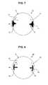
- the figure 1illustrates an antenna 1 comprising a concave primary reflector 2 and a secondary reflector 3.
- the antenna 1is fed by a waveguide 4 which may be a metal hollow tube, for example aluminum.
- the reflectors 2, 3are protected by a radome 5.
- This antenna 1does not have an absorbent skirt.
- the waveguide 4emits incident radiation towards the secondary reflector 3 which is reflected towards the primary reflector 2, forming the main beam 6 towards a receiver. However, part of the incident radiation is returned in a divergent direction and causes losses by overflow 7. Another part of the radiation is reflected by the primary reflector 2, but this reflected radiation is masked by the secondary reflector 3 which returns it again to the primary reflector 2. It is then reflected by the primary reflector 2 and returned in a divergent direction, causing loss by mask effect 8.
- an antenna 10comprises a concave primary reflector 11 and a secondary reflector 12.
- the antenna 10is powered by a waveguide 13.
- the reflectors 11, 12are protected by a radome 14.
- the waveguide 13emits a incident radiation towards the secondary reflector 12 , a portion 15 is returned in a divergent direction.
- Absorbent parts 16are disposed on the inner face of the radome 14 along the edge of the primary reflector 11. The diverging lateral radiation 15 is absorbed by the parts 16 and the overflow is thus avoided, without compromising the other characteristics.
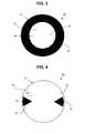
- the figure 3illustrates a first embodiment of a microwave antenna 30 reflector 31 deep concave circular opening, protected by a radome 32 which is here a rigid radome plan.
- a ring 33 of absorbent material of width H0is disposed on the inner face 34 of the radome 32 along the peripheral edge of the reflector 31.
- the width H0 of the absorbent ring 33depends on the reduction of the overflow.
- the presence of the absorbent ring 33makes it possible to significantly reduce the overflow losses.
- the impact of the absorbent ring 33 on the gain of the antenna 30will be relatively high because of the large area of the radome covered by the ring, which should not, however, exceed 25% of the surface area. total, and preferably not to exceed 15%.
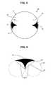
- Absorbent pieces 43are placed diametrically opposite to improve performance in the horizontal plane (azimuth plane) by acting in a skirt-like manner.
- the absorbent pieces 43are disposed on the inner face 44 of the radome 41 along its periphery which follows the edge of the reflector 41.
- the absorbent parts 43have a particular shape: here substantially triangular, the base of the absorbent part along the edge of the radome which is rounded. From the height H1 of the absorbent part depends the reduction of the overflow and the length B1 of the base of the absorbent part 43 acts on the forward / backward ratio of the antenna, that is to say the ratio between the intensity of the main lobe radiation at the front of the antenna and the intensity of the back lobe at 180 °, here in the horizontal plane.
- the absorbent parts 43cover at most 15% of the interior surface of the radome 42.
- Absorbent parts 53are arranged on the inner face 54 of the radome 52 along the edge of the reflector 51.
- the absorbent part 53is made of an absorbent material such as for example a carbon impregnated polyurethane foam.
- the thickness of an absorbent part 53is less than 20 mm, and preferably of the order of 12 mm.
- the absorbent pieces 53are placed diametrically opposite to improve the performance in the horizontal plane.
- the absorbent parts 53cover at most 15% of the inner surface of the radome 52. Above 15%, the impact of the presence of the absorbent parts 53 on the gain of the antenna becomes important and the secondary lobes of the radiation increase. In this case the absorbent parts 53 cover about 10% of the interior surface of the radome 52. The forward / backward ratio of the radiation pattern is then significantly improved with little impact on the gain (0.3 dB maximum).
- the length B2 of the base of the triangular absorbent piece 53is large enough to obtain a high forward / back ratio.
- the shape of the base of the absorbent part 53is adapted to that of the edge of the reflector to reduce effectively overflow without the need to increase the height H2 of the absorbent part 53.
- the height H2 of the absorbent part 53has a direct impact on the angle range around 60 ° of the radiation pattern of a deep parabolic reflector antenna.
- the length of the base B2is preferably between D / 5 and 2D / 5.
- the ratio B2 / H2 between the length of the base B2 and the height H2 of the absorbent part 53is preferably between 1 and 2: 1 ⁇ B2 / H2 ⁇ 2.
- the absorbent piecehas the shape of a triangle of which part of the surface has been removed.
- the particular shape of the absorbent piece 53is preferably obtained by eliminating rounded surfaces 60 on each side of the triangle in a cutout which may take the form of a circular arc 61, as shown in FIG. figure 6 for example, without modifying the height H2 of the absorbent part 53.
- the rounded surface or circular segment 60is a part of a disk 62 defined as a domain separated from the remainder of the disk 62 by a secant cord or straight line 63.
- the circular segment 60is the portion of the disk between the secant line 63 and the arc 61.
- the shape of the absorbent part 53is calculated to obtain a favorable compromise between the reduction of the overflow, the improvement of the forward / backward ratio and the impact on the gain of the antenna 50.
- the value of the electromagnetic field of the major part of the central surface of the radome 52decreases quite rapidly as one approaches the peripheral edge of the circular radome 52 .
- the particular shape of the absorbent part 53 placed near the edge of the radome 52makes it possible to create a progressive transition zone between the edge and the central surface of the radome 52.
- the particular shape of the absorbent pieceis preferably obtained from a substantially triangular shape by eliminating surfaces on the sides of the triangle so as to reduce the area corresponding to the tip of the triangle while preserving as much of the surface as possible. based.
- This shapeis obtained by a cutout which may in particular take the form of an arc 61 as illustrated on the Figures 5 and 6 , or a Gaussian curve, or else any other form to reach the purpose sought such as a triangle like on the figure 7 or a rectangle like on the figure 8 for example.
- the figure 7illustrates a fourth embodiment of a circular concave reflector 71 microwave antenna 70 protected by a radome 72 rigid plane of circular shape.
- Absorbent parts 73are disposed on the internal face 74 of the radome 72.
- the absorbent part 73has substantially the shape of a triangle of height H3 and a base length B3 whose surfaces 75 have been removed laterally by a substantially shaped cut. triangular.
- the base of the absorbent piece 73is rounded to conform to the shape of the edge of the circular opening of the reflector 72.
- the figure 8illustrates a fifth embodiment of a circular microwave antenna 80 reflector circular concave 81 protected by a radome 82 rigid plane of circular shape.
- Absorbent pieces 83are disposed on the inner face 84 of the radome 82.
- the absorbent piece 83has substantially the shape of a round-headed tee so as to match the shape of the edge of the circular opening of the reflector 82, of height H4 and base length B4. It derives from the triangular shape by removal of surfaces 85 substantially cut in the shape of an isosceles triangle, in particular a right isosceles triangle.
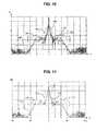
- the figure 9illustrates the radiation of a deep reflector antenna having a forward / backward ratio of 0.2.
- the main reflector of this antenna of the prior artdoes not have a skirt.
- Curve 90illustrates the radiation pattern in the 10GHz frequency band of the primary reflector in the horizontal plane.
- the reference curve 91represents the standard profile corresponding to the ETSI class 3 model. Zones 92 correspond to poor performance due to a high level of overflow losses. In zones 93, the side lobes exceed the ETSI standard. In the absence of a skirt, the direct consequence is that the radiation pattern has high overflow peaks in the angular areas 92 corresponding to the edge of the parabolic primary reflector, and an increase in the side lobes corresponding to the zones 93.
- the figure 10illustrates the radiation of a deep reflector antenna whose radome comprises absorbent parts according to the second embodiment.
- Curve 100illustrates the radiation pattern in the 10 GHz frequency band of the primary reflector in the horizontal plane.
- the reference curve 101represents the standard profile corresponding to the ETSI class 3 model.
- the zones 102correspond to the edge of the reflector where a smaller overflow occurs than in the previous figure.
- the zones 103correspond to the side lobes which are very much diminished.
- the values of the radiation diagramremain here within the limits of the maximum values allowed by the template of class 3 ETSI despite the absence of skirt.
- the figure 11illustrates the radiation pattern of a deep reflector antenna whose radome comprises absorbent parts according to the third embodiment.
- Curve 110illustrates the radiation pattern in the 10 GHz frequency band of the primary reflector in the horizontal plane.
- the reference curve 111represents the standard profile corresponding to the ETSI class 3 model.
- the zones 112correspond to the edge of the reflector where the overflow occurs and the zones 113 correspond to the side lobes.
- the present inventionis not limited to the described embodiments, but it is capable of many variants accessible to those skilled in the art without departing from the spirit of the invention.
- the described embodimentscomprise either an annular absorbent piece or two absorbent pieces in diametrically opposite position. It is possible to envisage using an even greater number (4, 6, 8, etc.) of absorbent part according to the compromise that one is willing to accept between the reduction of the parts by overflow and the impact on the gain. of the antenna.
- Several forms of the absorbent parthave been described in a nonlimiting manner, however, it will be possible to use different shapes obtained by removing side surfaces of various shapes.
Landscapes
- Aerials With Secondary Devices (AREA)
- Details Of Aerials (AREA)
Abstract
Translated fromFrench
Description
Translated fromFrenchLa présente invention se rapporte à une antenne de télécommunication à réflecteur concave ayant par exemple la forme d'au moins une portion de parabole,. Ces antennes, notamment de type micro-onde, sont utilisées habituellement dans les réseaux de communication mobile. Ces antennes fonctionnent indifféremment en mode transmetteur ou en mode récepteur, correspondant à deux sens opposés de propagation des ondes RF.The present invention relates to a telecommunication antenna with concave reflector having for example the shape of at least one parabola portion. These antennas, in particular of the microwave type, are usually used in mobile communication networks. These antennas operate indifferently in transmitter mode or in receiver mode, corresponding to two opposite directions of RF wave propagation.
Dans les antennes à réflecteur parabolique, la valeur du diamètre du réflecteur est déterminée par la fréquence centrale de travail de l'antenne. Plus la fréquence de travail de l'antenne est basse, plus le diamètre du réflecteur est important à gain d'antenne équivalent. Pour les antennes à réflecteur profond (« deep dish » en anglais), le rapport F/D est inférieur ou égal à 0,25. Dans ce rapport, F est la distance focale du réflecteur (distance entre le sommet du réflecteur et son foyer) et D est le diamètre du réflecteur. Ces antennes présentent des pertes par débordement (« spillover » en anglais) qui sont élevées et diminuent le rapport avant/arrière (« front-to-back ratio » en anglais) de l'antenne. Les pertes par débordement conduisent à une pollution de l'environnement par les ondes RF et doivent être limitées à des niveaux définis par des normes.In parabolic reflector antennas, the value of the reflector diameter is determined by the central working frequency of the antenna. The lower the working frequency of the antenna, the greater the diameter of the reflector at equivalent antenna gain. For antennas deep reflector ("deep dish" in English), the F / D ratio is less than or equal to 0.25. In this report, F is the focal length of the reflector (distance between the top of the reflector and its focus) and D is the diameter of the reflector. These antennas have spillover losses which are high and reduce the front-to-back ratio of the antenna. Overflow losses lead to environmental pollution by RF waves and must be limited to levels defined by standards.
Une solution habituelle est d'attacher à la périphérie du réflecteur parabolique une paroi cylindrique, appelée aussi jupe (« shroud » en anglais), de diamètre voisin de celui du réflecteur et de hauteur convenable, le plus souvent revêtue d'un matériau absorbant le rayonnement RF. L'utilisation d'une jupe absorbante onéreuse est nécessaire pour limiter l'effet de débordement et améliorer es performances de l'antenne. Néanmoins, cette solution augmente le coût de l'antenne, ses dimensions et rend plus complexe l'emballage pour le transportA usual solution is to attach to the periphery of the parabolic reflector a cylindrical wall, also called skirt ("shroud" in English), of diameter close to that of the reflector and of suitable height, most often coated with a material absorbing the RF radiation. The use of an expensive absorbent skirt is necessary to limit the overflow effect and improve the performance of the antenna. Nevertheless, this solution increases the cost of the antenna, its dimensions and makes more complex the packaging for the transport
Cependant la présence de la jupe augmente la prise au vent de l'antenne et le risque d'accumulation d'éléments polluant. Aussi on associe à la jupe un radôme qui présente une surface protectrice imperméable cloisonnant l'espace défini par le réflecteur et la jupe vis-à-vis de l'extérieur. Ce radôme peut être souple ou rigide, plan ou non, et de forme quelconque. Un radôme rigide circulaire, le plus utilisé actuellement, présente l'avantage d'une bonne résistance vis-à-vis de l'environnement climatique extérieur tel que pluie, vent ou neige.However the presence of the skirt increases the wind gain of the antenna and the risk of accumulation of pollutants. Also associated with the skirt a radome which has an impervious protective surface partitioning the space defined by the reflector and the skirt vis-à-vis the outside. This radome can be flexible or rigid, plane or not, and of any shape. A rigid circular radome, the most used at present, has the advantage of good resistance to the external climatic environment such as rain, wind or snow.
Pour éliminer ces inconvénients, on propose de supprimer la jupe. Toutefois en l'absence de jupe le rayonnement latéral de l'antenne subsiste et peut provoquer un débordement. On cherche donc à limiter ce débordement, tout en conservant des performances de même niveau que les antennes micro-ondes connues ayant un réflecteur parabolique munie d'une jupe.To eliminate these disadvantages, it is proposed to remove the skirt. However, in the absence of skirt, the lateral radiation of the antenna remains and can cause an overflow. It is therefore sought to limit this overflow, while maintaining performance at the same level as known microwave antennas having a parabolic reflector provided with a skirt.
Le but est donc de proposer un radôme permettant d'obtenir un diagramme de radiation conduisant à des performances satisfaisantes, conformes aux normes existantes, avec un faible impact sur le gain de l'antenne.The goal is to propose a radome to obtain a radiation pattern leading to satisfactory performance, consistent with existing standards, with a small impact on the gain of the antenna.
L'objet de la présente invention est un radôme pour une antenne à réflecteur concave, fixé directement sur le bord du réflecteur, la surface intérieure du radôme comportant au moins une pièce absorbante couvrant partiellement sa surface et disposée le long de son bord périphérique.The object of the present invention is a radome for a concave reflector antenna, fixed directly to the edge of the reflector, the inner surface of the radome having at least one absorbent piece partially covering its surface and disposed along its peripheral edge.
Le radôme est « fixé directement sur le bord du réflecteur » car le réflecteur ne comporte pas de jupe de telle sorte que le radôme n'est pas attaché à une jupe, mais directement au réflecteur.The radome is "fixed directly to the reflector edge" because the reflector has no skirt so that the radome is not attached to a skirt, but directly to the reflector.
De préférence la surface du radôme couverte par la ou les pièce(s) absorbante(s) est inférieure à 15% de la surface totale.Preferably the surface of the radome covered by the absorbent part (s) is less than 15% of the total area.
Selon un premier aspect, la pièce absorbante a une forme annulaire.According to a first aspect, the absorbent piece has an annular shape.
Selon un deuxième aspect, la pièce absorbante a une forme sensiblement triangulaire, la base de la pièce absorbante étant arrondie suivant le bord du radôme.According to a second aspect, the absorbent part has a substantially triangular shape, the base of the absorbent part being rounded along the edge of the radome.
Selon un mode de réalisation préféré, la pièce absorbante a une forme sensiblement triangulaire, une partie de sa surface ayant été enlevée latéralement, la base de la pièce absorbante suivant le bord du radôme.According to a preferred embodiment, the absorbent piece has a substantially triangular shape, a part of its surface having been removed laterally, the base of the absorbent piece following the edge of the radome.
Selon une variante, la partie de surface enlevée est constituée par l'élimination de surfaces de chaque côté du triangle selon une découpe en arc de cercle.Alternatively, the removed surface portion is constituted by the removal of surfaces on each side of the triangle in an arcuate cut.
Selon une autre variante, la partie de surface enlevée est constituée par l'élimination de surfaces de chaque côté du triangle selon une découpe en forme de triangle isocèle.According to another variant, the removed surface portion consists of the elimination of surfaces on each side of the triangle in an isosceles triangle-shaped cutout.
De préférence, le radôme comporte deux pièces absorbantes en position diamétralement opposée.Preferably, the radome comprises two absorbent parts in diametrically opposite position.
Le radôme a été modifié par l'ajout de pièces constituées d'un matériau absorbant avec une forme particulièrement étudiée pour réduire le débordement et au moins conserver les performances du diagramme de rayonnement avec le plus faible impact sur le gain, sans qu'il soit nécessaire d'ajouter une jupe.The radome has been modified by the addition of absorbent material parts with a particularly studied shape to reduce the overflow and at least maintain the performance of the radiation pattern with the least impact on the gain, without it being necessary to add a skirt.
Selon une forme d'exécution, la longueur de la base de la pièce absorbante est comprise entre D/5 et 2D/5 où D est le diamètre du radôme.According to one embodiment, the length of the base of the absorbent part is between D / 5 and 2D / 5 where D is the diameter of the radome.
Selon une autre forme d'exécution, le rapport de la longueur de la base de la pièce absorbante à la hauteur de la pièce absorbante est compris entre 1 et 2.According to another embodiment, the ratio of the length of the base of the absorbent part to the height of the absorbent part is between 1 and 2.
L'invention a encore pour objet une antenne à réflecteur concave comportant un radôme fixé directement sur le bord du réflecteur, la surface intérieure du radôme comportant au moins une pièce absorbante couvrant partiellement sa surface et disposée le long de son bord périphérique.The invention further relates to a concave reflector antenna having a radome fixed directly on the edge of the reflector, the inner surface of the radome having at least one absorbent piece partially covering its surface and disposed along its peripheral edge.
Selon un mode particulier de réalisation, le radôme est circulaire, plan et rigide.According to a particular embodiment, the radome is circular, plane and rigid.
Une antenne micro-ondes à faible débordement est une garantie de qualité d'émission/réception car elle permet de réaliser la liaison radio avec de très faibles interférences entre les antennes voisines, en particulier dans une zone à forte densité d'antennes. En outre cette antenne est moins onéreuse, de taille réduite et d'un transport plus facile que les antennes de l'art antérieur.A microwave antenna with low overflow is a guarantee of transmission / reception quality because it makes it possible to achieve the radio link with very little interference between the neighboring antennas, in particular in a zone with a high density of antennas. In addition this antenna is less expensive, smaller in size and easier to transport than antennas of the prior art.
D'autres caractéristiques et avantages de la présente invention apparaîtront à la lecture de la description qui suit d'un mode de réalisation, donné bien entendu à titre illustratif et non limitatif, et dans le dessin annexé sur lequel
- la
figure 1 illustre schématiquement en coupe une antenne micro-onde à double réflecteur ne comportant pas de jupe absorbante, - la
figure 2 illustre schématiquement en coupe une antenne micro-onde à double réflecteur selon un mode de réalisation, - la
figure 3 illustre schématiquement la face interne d'un radôme selon un premier mode de réalisation, - la
figure 4 illustre schématiquement la face interne d'un radôme selon un deuxième mode de réalisation, - la
figure 5 illustre schématiquement la face interne d'un radôme selon un troisième mode de réalisation, - la
figure 6 illustre schématiquement en détail la forme de la pièce diélectrique selon le troisième mode de réalisation, - la
figure 7 illustre schématiquement la face interne d'un radôme selon un quatrième mode de réalisation, - la
figure 8 illustre schématiquement la face interne d'un radôme selon un cinquième mode de réalisation, - la
figure 9 illustre le diagramme de rayonnement dans le plan horizontal d'une antenne de l'art antérieur ne comportant pas de jupe, - la
figure 10 illustre le diagramme de rayonnement dans le plan horizontal d'une antenne selon le deuxième mode de réalisation, - la
figure 11 illustre le diagramme de rayonnement dans le plan horizontal d'une antenne selon le troisième mode de réalisation.
- the
figure 1 schematically illustrates in section a microwave antenna with double reflector having no absorbent skirt, - the
figure 2 schematically illustrates in section a microwave antenna with double reflector according to one embodiment, - the
figure 3 schematically illustrates the internal face of a radome according to a first embodiment, - the
figure 4 schematically illustrates the internal face of a radome according to a second embodiment, - the
figure 5 schematically illustrates the internal face of a radome according to a third embodiment, - the
figure 6 schematically illustrates in detail the shape of the dielectric piece according to the third embodiment, - the
figure 7 schematically illustrates the internal face of a radome according to a fourth embodiment, - the
figure 8 schematically illustrates the internal face of a radome according to a fifth embodiment, - the
figure 9 illustrates the radiation pattern in the horizontal plane of a prior art antenna having no skirt, - the
figure 10 illustrates the radiation pattern in the horizontal plane of an antenna according to the second embodiment, - the
figure 11 illustrates the radiation pattern in the horizontal plane of an antenna according to the third embodiment.
Sur les
La
Dans le mode de réalisation de l'invention illustré sur la
La
On considérera maintenant la
Les pièces absorbantes43 ont une forme particulière : ici sensiblement triangulaire, la base de la pièce absorbante suivant le bord du radôme qui est arrondi. De la hauteurH1 de la pièce absorbante dépend la réduction du débordement et la longueurB1 de la base de la pièce absorbante43 agit sur le rapport avant/arrière de l'antenne, c'est-à-dire le rapport entre l'intensité de rayonnement du lobe principal à l'avant de l'antenne et l'intensité du lobe arrière à 180°, ici dans le plan horizontal. Les pièces absorbantes43 couvrent au plus 15% de la surface intérieure du radôme42.The
La
Les pièces absorbantes53 sont placées de manière diamétralement opposée pour améliorer les performances dans le plan horizontal. Les pièces absorbantes53 couvrent au plus 15% de la surface intérieure du radôme52. Au-delà de 15%, l'impact de la présence des pièces absorbantes53 sur le gain de l'antenne devient important et les lobes secondaires du diagramme de rayonnement augmentent. Dans le cas présent les pièces absorbantes53 couvrent environ 10% de la surface intérieure du radôme52. Le rapport avant/arrière du diagramme de rayonnement est alors significativement amélioré avec peu d'impact sur le gain (0,3 dB au maximum).The
La longueurB2 de la base de la pièce absorbante53 triangulaire est suffisamment importante pour obtenir un rapport avant/arrière élevé. La forme de la base de la pièce absorbante53 est adaptée à celle du bord du réflecteur afin de réduire efficacement le débordement sans qu'il soit nécessaire d'augmenter la hauteurH2 de la pièce absorbante53. La hauteurH2 de la pièce absorbante53 a un impact direct sur le domaine d'angle autour de 60° du diagramme de rayonnement d'une antenne à réflecteur parabolique profond. Par exemple, dans le cas d'un réflecteur concave à ouverture circulaire de diamètre D, la longueur de la baseB2 est de préférence comprise entre D/5 et 2D/5. Le rapport B2/H2 entre la longueur de la baseB2 et la hauteurH2 de la pièce absorbante53 est de préférence compris entre 1 et 2 : 1 ≤ B2/H2 ≤ 2. Ces valeurs permettent d'atteindre un résultat en termes de réduction du débordement et de rapport avant/arrière qui est significatif et permet un fonctionnement pleinement satisfaisant d'une telle antenne.The lengthB2 of the base of the triangular
Dans ce mode de réalisation la pièce absorbante a la forme d'un triangle dont une partie de la surface a été enlevée. La forme particulière de la pièce absorbante53 est obtenue de préférence en éliminant des surfaces60 arrondies de chaque côté du triangle selon une découpe qui peut prendre la forme d'un arc de cercle61, comme illustré sur la
La forme particulière de la pièce absorbante est de préférence obtenue à partir d'une forme sensiblement triangulaire en éliminant des surfaces sur les côtés du triangle de manière à réduire la surface correspondant à la pointe du triangle tout en préservant le plus possible de surface à la base. Cette forme est obtenue par une découpe qui peut notamment prendre la forme d'un arc de cercle61 comme illustré sur les
La
La
La
La
La
En comparant les courbes100 et110, relatives respectivement aux modes de réalisation des
Bien entendu, la présente invention n'est pas limitée aux modes de réalisation décrits, mais elle est susceptible de nombreuses variantes accessibles à l'homme de l'art sans que l'on s'écarte de l'esprit de l'invention. En particulier, on pourra sans sortir du cadre de l'invention modifier le nombre et la forme des pièces absorbantes. Les modes de réalisation décrits comporte soit une pièce absorbante annulaire, soit deux pièces absorbantes en position diamétralement opposées. On peut envisager d'utiliser un nombre pair supérieur (4, 6, 8, etc...) de pièce absorbante selon le compromis que l'on est disposé à accepter entre la réduction des partes par débordement et l'impact sur le gain de l'antenne. Plusieurs formes de la pièce absorbante ont été décrites de manière non limitative, néanmoins on pourra utiliser des formes différentes obtenues par enlèvement de surfaces latérales de formes variées.Of course, the present invention is not limited to the described embodiments, but it is capable of many variants accessible to those skilled in the art without departing from the spirit of the invention. In particular, without departing from the scope of the invention, it will be possible to modify the number and the shape of the absorbent parts. The described embodiments comprise either an annular absorbent piece or two absorbent pieces in diametrically opposite position. It is possible to envisage using an even greater number (4, 6, 8, etc.) of absorbent part according to the compromise that one is willing to accept between the reduction of the parts by overflow and the impact on the gain. of the antenna. Several forms of the absorbent part have been described in a nonlimiting manner, however, it will be possible to use different shapes obtained by removing side surfaces of various shapes.
Claims (12)
Translated fromFrenchPriority Applications (4)
| Application Number | Priority Date | Filing Date | Title |
|---|---|---|---|
| EP13305610.1AEP2804259B1 (en) | 2013-05-15 | 2013-05-15 | Radome for a concave reflector antenna |
| US14/890,701US10224640B2 (en) | 2013-05-15 | 2014-05-14 | Radome for an antenna with a concave-reflector |
| CN201480027457.XACN105556746B (en) | 2013-05-15 | 2014-05-14 | Radomes for Antennas with Concave Reflectors |
| PCT/IB2014/061437WO2014184755A2 (en) | 2013-05-15 | 2014-05-14 | Radome for an antenna with a concave-reflector |
Applications Claiming Priority (1)
| Application Number | Priority Date | Filing Date | Title |
|---|---|---|---|
| EP13305610.1AEP2804259B1 (en) | 2013-05-15 | 2013-05-15 | Radome for a concave reflector antenna |
Publications (2)
| Publication Number | Publication Date |
|---|---|
| EP2804259A1true EP2804259A1 (en) | 2014-11-19 |
| EP2804259B1 EP2804259B1 (en) | 2019-09-18 |
Family
ID=48577653
Family Applications (1)
| Application Number | Title | Priority Date | Filing Date |
|---|---|---|---|
| EP13305610.1AActiveEP2804259B1 (en) | 2013-05-15 | 2013-05-15 | Radome for a concave reflector antenna |
Country Status (4)
| Country | Link |
|---|---|
| US (1) | US10224640B2 (en) |
| EP (1) | EP2804259B1 (en) |
| CN (1) | CN105556746B (en) |
| WO (1) | WO2014184755A2 (en) |
Cited By (141)
| Publication number | Priority date | Publication date | Assignee | Title |
|---|---|---|---|---|
| WO2014184755A3 (en)* | 2013-05-15 | 2015-04-09 | Alcatel-Lucent Shanghai Bell Co.,Ltd | Radome for an antenna with a concave-reflector |
| EP2924804A1 (en)* | 2014-03-28 | 2015-09-30 | Alcatel- Lucent Shanghai Bell Co., Ltd | Radome with absorbent device, and antenna comprising same |
| WO2016089623A1 (en)* | 2014-12-02 | 2016-06-09 | Commscope Technologies Llc | Antenna radome with absorbers |
| US9608740B2 (en) | 2015-07-15 | 2017-03-28 | At&T Intellectual Property I, L.P. | Method and apparatus for launching a wave mode that mitigates interference |
| US9640850B2 (en) | 2015-06-25 | 2017-05-02 | At&T Intellectual Property I, L.P. | Methods and apparatus for inducing a non-fundamental wave mode on a transmission medium |
| US9667317B2 (en) | 2015-06-15 | 2017-05-30 | At&T Intellectual Property I, L.P. | Method and apparatus for providing security using network traffic adjustments |
| US9674711B2 (en) | 2013-11-06 | 2017-06-06 | At&T Intellectual Property I, L.P. | Surface-wave communications and methods thereof |
| US9685992B2 (en) | 2014-10-03 | 2017-06-20 | At&T Intellectual Property I, L.P. | Circuit panel network and methods thereof |
| US9705610B2 (en) | 2014-10-21 | 2017-07-11 | At&T Intellectual Property I, L.P. | Transmission device with impairment compensation and methods for use therewith |
| US9705561B2 (en) | 2015-04-24 | 2017-07-11 | At&T Intellectual Property I, L.P. | Directional coupling device and methods for use therewith |
| US9722318B2 (en) | 2015-07-14 | 2017-08-01 | At&T Intellectual Property I, L.P. | Method and apparatus for coupling an antenna to a device |
| US9729197B2 (en) | 2015-10-01 | 2017-08-08 | At&T Intellectual Property I, L.P. | Method and apparatus for communicating network management traffic over a network |
| US9735833B2 (en) | 2015-07-31 | 2017-08-15 | At&T Intellectual Property I, L.P. | Method and apparatus for communications management in a neighborhood network |
| US9742462B2 (en) | 2014-12-04 | 2017-08-22 | At&T Intellectual Property I, L.P. | Transmission medium and communication interfaces and methods for use therewith |
| US9742521B2 (en) | 2014-11-20 | 2017-08-22 | At&T Intellectual Property I, L.P. | Transmission device with mode division multiplexing and methods for use therewith |
| US9749053B2 (en) | 2015-07-23 | 2017-08-29 | At&T Intellectual Property I, L.P. | Node device, repeater and methods for use therewith |
| US9749013B2 (en) | 2015-03-17 | 2017-08-29 | At&T Intellectual Property I, L.P. | Method and apparatus for reducing attenuation of electromagnetic waves guided by a transmission medium |
| US9748626B2 (en) | 2015-05-14 | 2017-08-29 | At&T Intellectual Property I, L.P. | Plurality of cables having different cross-sectional shapes which are bundled together to form a transmission medium |
| US9762289B2 (en) | 2014-10-14 | 2017-09-12 | At&T Intellectual Property I, L.P. | Method and apparatus for transmitting or receiving signals in a transportation system |
| US9768833B2 (en) | 2014-09-15 | 2017-09-19 | At&T Intellectual Property I, L.P. | Method and apparatus for sensing a condition in a transmission medium of electromagnetic waves |
| US9769020B2 (en) | 2014-10-21 | 2017-09-19 | At&T Intellectual Property I, L.P. | Method and apparatus for responding to events affecting communications in a communication network |
| US9769128B2 (en) | 2015-09-28 | 2017-09-19 | At&T Intellectual Property I, L.P. | Method and apparatus for encryption of communications over a network |
| US9780834B2 (en) | 2014-10-21 | 2017-10-03 | At&T Intellectual Property I, L.P. | Method and apparatus for transmitting electromagnetic waves |
| US9788326B2 (en) | 2012-12-05 | 2017-10-10 | At&T Intellectual Property I, L.P. | Backhaul link for distributed antenna system |
| US9787412B2 (en) | 2015-06-25 | 2017-10-10 | At&T Intellectual Property I, L.P. | Methods and apparatus for inducing a fundamental wave mode on a transmission medium |
| US9793951B2 (en) | 2015-07-15 | 2017-10-17 | At&T Intellectual Property I, L.P. | Method and apparatus for launching a wave mode that mitigates interference |
| US9793955B2 (en) | 2015-04-24 | 2017-10-17 | At&T Intellectual Property I, Lp | Passive electrical coupling device and methods for use therewith |
| US9793954B2 (en) | 2015-04-28 | 2017-10-17 | At&T Intellectual Property I, L.P. | Magnetic coupling device and methods for use therewith |
| US9800327B2 (en) | 2014-11-20 | 2017-10-24 | At&T Intellectual Property I, L.P. | Apparatus for controlling operations of a communication device and methods thereof |
| US9820146B2 (en) | 2015-06-12 | 2017-11-14 | At&T Intellectual Property I, L.P. | Method and apparatus for authentication and identity management of communicating devices |
| US9838896B1 (en) | 2016-12-09 | 2017-12-05 | At&T Intellectual Property I, L.P. | Method and apparatus for assessing network coverage |
| US9838078B2 (en) | 2015-07-31 | 2017-12-05 | At&T Intellectual Property I, L.P. | Method and apparatus for exchanging communication signals |
| US9847850B2 (en) | 2014-10-14 | 2017-12-19 | At&T Intellectual Property I, L.P. | Method and apparatus for adjusting a mode of communication in a communication network |
| US9847566B2 (en) | 2015-07-14 | 2017-12-19 | At&T Intellectual Property I, L.P. | Method and apparatus for adjusting a field of a signal to mitigate interference |
| US9853342B2 (en) | 2015-07-14 | 2017-12-26 | At&T Intellectual Property I, L.P. | Dielectric transmission medium connector and methods for use therewith |
| US9860075B1 (en) | 2016-08-26 | 2018-01-02 | At&T Intellectual Property I, L.P. | Method and communication node for broadband distribution |
| US9866276B2 (en) | 2014-10-10 | 2018-01-09 | At&T Intellectual Property I, L.P. | Method and apparatus for arranging communication sessions in a communication system |
| US9866309B2 (en) | 2015-06-03 | 2018-01-09 | At&T Intellectual Property I, Lp | Host node device and methods for use therewith |
| US9865911B2 (en) | 2015-06-25 | 2018-01-09 | At&T Intellectual Property I, L.P. | Waveguide system for slot radiating first electromagnetic waves that are combined into a non-fundamental wave mode second electromagnetic wave on a transmission medium |
| US9871282B2 (en) | 2015-05-14 | 2018-01-16 | At&T Intellectual Property I, L.P. | At least one transmission medium having a dielectric surface that is covered at least in part by a second dielectric |
| US9871283B2 (en) | 2015-07-23 | 2018-01-16 | At&T Intellectual Property I, Lp | Transmission medium having a dielectric core comprised of plural members connected by a ball and socket configuration |
| US9871558B2 (en) | 2014-10-21 | 2018-01-16 | At&T Intellectual Property I, L.P. | Guided-wave transmission device and methods for use therewith |
| US9876264B2 (en) | 2015-10-02 | 2018-01-23 | At&T Intellectual Property I, Lp | Communication system, guided wave switch and methods for use therewith |
| US9876571B2 (en) | 2015-02-20 | 2018-01-23 | At&T Intellectual Property I, Lp | Guided-wave transmission device with non-fundamental mode propagation and methods for use therewith |
| US9876605B1 (en) | 2016-10-21 | 2018-01-23 | At&T Intellectual Property I, L.P. | Launcher and coupling system to support desired guided wave mode |
| US9882257B2 (en) | 2015-07-14 | 2018-01-30 | At&T Intellectual Property I, L.P. | Method and apparatus for launching a wave mode that mitigates interference |
| US9887447B2 (en) | 2015-05-14 | 2018-02-06 | At&T Intellectual Property I, L.P. | Transmission medium having multiple cores and methods for use therewith |
| US9893795B1 (en) | 2016-12-07 | 2018-02-13 | At&T Intellectual Property I, Lp | Method and repeater for broadband distribution |
| US9906269B2 (en) | 2014-09-17 | 2018-02-27 | At&T Intellectual Property I, L.P. | Monitoring and mitigating conditions in a communication network |
| US9913139B2 (en) | 2015-06-09 | 2018-03-06 | At&T Intellectual Property I, L.P. | Signal fingerprinting for authentication of communicating devices |
| US9912382B2 (en) | 2015-06-03 | 2018-03-06 | At&T Intellectual Property I, Lp | Network termination and methods for use therewith |
| US9912033B2 (en) | 2014-10-21 | 2018-03-06 | At&T Intellectual Property I, Lp | Guided wave coupler, coupling module and methods for use therewith |
| US9912027B2 (en) | 2015-07-23 | 2018-03-06 | At&T Intellectual Property I, L.P. | Method and apparatus for exchanging communication signals |
| US9912419B1 (en) | 2016-08-24 | 2018-03-06 | At&T Intellectual Property I, L.P. | Method and apparatus for managing a fault in a distributed antenna system |
| US9911020B1 (en) | 2016-12-08 | 2018-03-06 | At&T Intellectual Property I, L.P. | Method and apparatus for tracking via a radio frequency identification device |
| US9917341B2 (en) | 2015-05-27 | 2018-03-13 | At&T Intellectual Property I, L.P. | Apparatus and method for launching electromagnetic waves and for modifying radial dimensions of the propagating electromagnetic waves |
| US9929755B2 (en) | 2015-07-14 | 2018-03-27 | At&T Intellectual Property I, L.P. | Method and apparatus for coupling an antenna to a device |
| US9927517B1 (en) | 2016-12-06 | 2018-03-27 | At&T Intellectual Property I, L.P. | Apparatus and methods for sensing rainfall |
| US9930668B2 (en) | 2013-05-31 | 2018-03-27 | At&T Intellectual Property I, L.P. | Remote distributed antenna system |
| US9948355B2 (en) | 2014-10-21 | 2018-04-17 | At&T Intellectual Property I, L.P. | Apparatus for providing communication services and methods thereof |
| US9948333B2 (en) | 2015-07-23 | 2018-04-17 | At&T Intellectual Property I, L.P. | Method and apparatus for wireless communications to mitigate interference |
| US9948354B2 (en) | 2015-04-28 | 2018-04-17 | At&T Intellectual Property I, L.P. | Magnetic coupling device with reflective plate and methods for use therewith |
| US9954287B2 (en) | 2014-11-20 | 2018-04-24 | At&T Intellectual Property I, L.P. | Apparatus for converting wireless signals and electromagnetic waves and methods thereof |
| US9954286B2 (en) | 2014-10-21 | 2018-04-24 | At&T Intellectual Property I, L.P. | Guided-wave transmission device with non-fundamental mode propagation and methods for use therewith |
| US9967173B2 (en) | 2015-07-31 | 2018-05-08 | At&T Intellectual Property I, L.P. | Method and apparatus for authentication and identity management of communicating devices |
| US9973940B1 (en) | 2017-02-27 | 2018-05-15 | At&T Intellectual Property I, L.P. | Apparatus and methods for dynamic impedance matching of a guided wave launcher |
| US9973416B2 (en) | 2014-10-02 | 2018-05-15 | At&T Intellectual Property I, L.P. | Method and apparatus that provides fault tolerance in a communication network |
| US9991580B2 (en) | 2016-10-21 | 2018-06-05 | At&T Intellectual Property I, L.P. | Launcher and coupling system for guided wave mode cancellation |
| US9997819B2 (en) | 2015-06-09 | 2018-06-12 | At&T Intellectual Property I, L.P. | Transmission medium and method for facilitating propagation of electromagnetic waves via a core |
| US9999038B2 (en) | 2013-05-31 | 2018-06-12 | At&T Intellectual Property I, L.P. | Remote distributed antenna system |
| US9998870B1 (en) | 2016-12-08 | 2018-06-12 | At&T Intellectual Property I, L.P. | Method and apparatus for proximity sensing |
| US10009063B2 (en) | 2015-09-16 | 2018-06-26 | At&T Intellectual Property I, L.P. | Method and apparatus for use with a radio distributed antenna system having an out-of-band reference signal |
| US10009067B2 (en) | 2014-12-04 | 2018-06-26 | At&T Intellectual Property I, L.P. | Method and apparatus for configuring a communication interface |
| US10020844B2 (en) | 2016-12-06 | 2018-07-10 | T&T Intellectual Property I, L.P. | Method and apparatus for broadcast communication via guided waves |
| US10027398B2 (en) | 2015-06-11 | 2018-07-17 | At&T Intellectual Property I, Lp | Repeater and methods for use therewith |
| US10027397B2 (en) | 2016-12-07 | 2018-07-17 | At&T Intellectual Property I, L.P. | Distributed antenna system and methods for use therewith |
| US10033108B2 (en) | 2015-07-14 | 2018-07-24 | At&T Intellectual Property I, L.P. | Apparatus and methods for generating an electromagnetic wave having a wave mode that mitigates interference |
| US10044409B2 (en) | 2015-07-14 | 2018-08-07 | At&T Intellectual Property I, L.P. | Transmission medium and methods for use therewith |
| US10069535B2 (en) | 2016-12-08 | 2018-09-04 | At&T Intellectual Property I, L.P. | Apparatus and methods for launching electromagnetic waves having a certain electric field structure |
| US10079661B2 (en) | 2015-09-16 | 2018-09-18 | At&T Intellectual Property I, L.P. | Method and apparatus for use with a radio distributed antenna system having a clock reference |
| US10090606B2 (en) | 2015-07-15 | 2018-10-02 | At&T Intellectual Property I, L.P. | Antenna system with dielectric array and methods for use therewith |
| US10090594B2 (en) | 2016-11-23 | 2018-10-02 | At&T Intellectual Property I, L.P. | Antenna system having structural configurations for assembly |
| US10103422B2 (en) | 2016-12-08 | 2018-10-16 | At&T Intellectual Property I, L.P. | Method and apparatus for mounting network devices |
| US10103801B2 (en) | 2015-06-03 | 2018-10-16 | At&T Intellectual Property I, L.P. | Host node device and methods for use therewith |
| US10135145B2 (en) | 2016-12-06 | 2018-11-20 | At&T Intellectual Property I, L.P. | Apparatus and methods for generating an electromagnetic wave along a transmission medium |
| US10135147B2 (en) | 2016-10-18 | 2018-11-20 | At&T Intellectual Property I, L.P. | Apparatus and methods for launching guided waves via an antenna |
| US10135146B2 (en) | 2016-10-18 | 2018-11-20 | At&T Intellectual Property I, L.P. | Apparatus and methods for launching guided waves via circuits |
| US10136434B2 (en) | 2015-09-16 | 2018-11-20 | At&T Intellectual Property I, L.P. | Method and apparatus for use with a radio distributed antenna system having an ultra-wideband control channel |
| US10139820B2 (en) | 2016-12-07 | 2018-11-27 | At&T Intellectual Property I, L.P. | Method and apparatus for deploying equipment of a communication system |
| US10148016B2 (en) | 2015-07-14 | 2018-12-04 | At&T Intellectual Property I, L.P. | Apparatus and methods for communicating utilizing an antenna array |
| US10144036B2 (en) | 2015-01-30 | 2018-12-04 | At&T Intellectual Property I, L.P. | Method and apparatus for mitigating interference affecting a propagation of electromagnetic waves guided by a transmission medium |
| US10170840B2 (en) | 2015-07-14 | 2019-01-01 | At&T Intellectual Property I, L.P. | Apparatus and methods for sending or receiving electromagnetic signals |
| US10168695B2 (en) | 2016-12-07 | 2019-01-01 | At&T Intellectual Property I, L.P. | Method and apparatus for controlling an unmanned aircraft |
| US10178445B2 (en) | 2016-11-23 | 2019-01-08 | At&T Intellectual Property I, L.P. | Methods, devices, and systems for load balancing between a plurality of waveguides |
| US10205655B2 (en) | 2015-07-14 | 2019-02-12 | At&T Intellectual Property I, L.P. | Apparatus and methods for communicating utilizing an antenna array and multiple communication paths |
| US10224634B2 (en) | 2016-11-03 | 2019-03-05 | At&T Intellectual Property I, L.P. | Methods and apparatus for adjusting an operational characteristic of an antenna |
| US10225025B2 (en) | 2016-11-03 | 2019-03-05 | At&T Intellectual Property I, L.P. | Method and apparatus for detecting a fault in a communication system |
| US10243270B2 (en) | 2016-12-07 | 2019-03-26 | At&T Intellectual Property I, L.P. | Beam adaptive multi-feed dielectric antenna system and methods for use therewith |
| US10243784B2 (en) | 2014-11-20 | 2019-03-26 | At&T Intellectual Property I, L.P. | System for generating topology information and methods thereof |
| US10264586B2 (en) | 2016-12-09 | 2019-04-16 | At&T Mobility Ii Llc | Cloud-based packet controller and methods for use therewith |
| US10291311B2 (en) | 2016-09-09 | 2019-05-14 | At&T Intellectual Property I, L.P. | Method and apparatus for mitigating a fault in a distributed antenna system |
| US10291334B2 (en) | 2016-11-03 | 2019-05-14 | At&T Intellectual Property I, L.P. | System for detecting a fault in a communication system |
| US10298293B2 (en) | 2017-03-13 | 2019-05-21 | At&T Intellectual Property I, L.P. | Apparatus of communication utilizing wireless network devices |
| US10305190B2 (en) | 2016-12-01 | 2019-05-28 | At&T Intellectual Property I, L.P. | Reflecting dielectric antenna system and methods for use therewith |
| US10312567B2 (en) | 2016-10-26 | 2019-06-04 | At&T Intellectual Property I, L.P. | Launcher with planar strip antenna and methods for use therewith |
| US10320586B2 (en) | 2015-07-14 | 2019-06-11 | At&T Intellectual Property I, L.P. | Apparatus and methods for generating non-interfering electromagnetic waves on an insulated transmission medium |
| US10326494B2 (en) | 2016-12-06 | 2019-06-18 | At&T Intellectual Property I, L.P. | Apparatus for measurement de-embedding and methods for use therewith |
| US10326689B2 (en) | 2016-12-08 | 2019-06-18 | At&T Intellectual Property I, L.P. | Method and system for providing alternative communication paths |
| US10340983B2 (en) | 2016-12-09 | 2019-07-02 | At&T Intellectual Property I, L.P. | Method and apparatus for surveying remote sites via guided wave communications |
| US10341142B2 (en) | 2015-07-14 | 2019-07-02 | At&T Intellectual Property I, L.P. | Apparatus and methods for generating non-interfering electromagnetic waves on an uninsulated conductor |
| US10340573B2 (en) | 2016-10-26 | 2019-07-02 | At&T Intellectual Property I, L.P. | Launcher with cylindrical coupling device and methods for use therewith |
| US10340600B2 (en) | 2016-10-18 | 2019-07-02 | At&T Intellectual Property I, L.P. | Apparatus and methods for launching guided waves via plural waveguide systems |
| US10340601B2 (en) | 2016-11-23 | 2019-07-02 | At&T Intellectual Property I, L.P. | Multi-antenna system and methods for use therewith |
| US10340603B2 (en) | 2016-11-23 | 2019-07-02 | At&T Intellectual Property I, L.P. | Antenna system having shielded structural configurations for assembly |
| US10355367B2 (en) | 2015-10-16 | 2019-07-16 | At&T Intellectual Property I, L.P. | Antenna structure for exchanging wireless signals |
| US10361489B2 (en) | 2016-12-01 | 2019-07-23 | At&T Intellectual Property I, L.P. | Dielectric dish antenna system and methods for use therewith |
| US10359749B2 (en) | 2016-12-07 | 2019-07-23 | At&T Intellectual Property I, L.P. | Method and apparatus for utilities management via guided wave communication |
| US10374316B2 (en) | 2016-10-21 | 2019-08-06 | At&T Intellectual Property I, L.P. | System and dielectric antenna with non-uniform dielectric |
| US10382976B2 (en) | 2016-12-06 | 2019-08-13 | At&T Intellectual Property I, L.P. | Method and apparatus for managing wireless communications based on communication paths and network device positions |
| US10389037B2 (en) | 2016-12-08 | 2019-08-20 | At&T Intellectual Property I, L.P. | Apparatus and methods for selecting sections of an antenna array and use therewith |
| US10389029B2 (en) | 2016-12-07 | 2019-08-20 | At&T Intellectual Property I, L.P. | Multi-feed dielectric antenna system with core selection and methods for use therewith |
| US10411356B2 (en) | 2016-12-08 | 2019-09-10 | At&T Intellectual Property I, L.P. | Apparatus and methods for selectively targeting communication devices with an antenna array |
| US10439675B2 (en) | 2016-12-06 | 2019-10-08 | At&T Intellectual Property I, L.P. | Method and apparatus for repeating guided wave communication signals |
| US10446936B2 (en) | 2016-12-07 | 2019-10-15 | At&T Intellectual Property I, L.P. | Multi-feed dielectric antenna system and methods for use therewith |
| US10498044B2 (en) | 2016-11-03 | 2019-12-03 | At&T Intellectual Property I, L.P. | Apparatus for configuring a surface of an antenna |
| US10530505B2 (en) | 2016-12-08 | 2020-01-07 | At&T Intellectual Property I, L.P. | Apparatus and methods for launching electromagnetic waves along a transmission medium |
| US10535928B2 (en) | 2016-11-23 | 2020-01-14 | At&T Intellectual Property I, L.P. | Antenna system and methods for use therewith |
| US10547348B2 (en) | 2016-12-07 | 2020-01-28 | At&T Intellectual Property I, L.P. | Method and apparatus for switching transmission mediums in a communication system |
| US10601494B2 (en) | 2016-12-08 | 2020-03-24 | At&T Intellectual Property I, L.P. | Dual-band communication device and method for use therewith |
| US10637149B2 (en) | 2016-12-06 | 2020-04-28 | At&T Intellectual Property I, L.P. | Injection molded dielectric antenna and methods for use therewith |
| US10650940B2 (en) | 2015-05-15 | 2020-05-12 | At&T Intellectual Property I, L.P. | Transmission medium having a conductive material and methods for use therewith |
| US10694379B2 (en) | 2016-12-06 | 2020-06-23 | At&T Intellectual Property I, L.P. | Waveguide system with device-based authentication and methods for use therewith |
| US10727599B2 (en) | 2016-12-06 | 2020-07-28 | At&T Intellectual Property I, L.P. | Launcher with slot antenna and methods for use therewith |
| US10755542B2 (en) | 2016-12-06 | 2020-08-25 | At&T Intellectual Property I, L.P. | Method and apparatus for surveillance via guided wave communication |
| US10777873B2 (en) | 2016-12-08 | 2020-09-15 | At&T Intellectual Property I, L.P. | Method and apparatus for mounting network devices |
| US10797781B2 (en) | 2015-06-03 | 2020-10-06 | At&T Intellectual Property I, L.P. | Client node device and methods for use therewith |
| US10811767B2 (en) | 2016-10-21 | 2020-10-20 | At&T Intellectual Property I, L.P. | System and dielectric antenna with convex dielectric radome |
| US10819035B2 (en) | 2016-12-06 | 2020-10-27 | At&T Intellectual Property I, L.P. | Launcher with helical antenna and methods for use therewith |
| US10916969B2 (en) | 2016-12-08 | 2021-02-09 | At&T Intellectual Property I, L.P. | Method and apparatus for providing power using an inductive coupling |
| US10938108B2 (en) | 2016-12-08 | 2021-03-02 | At&T Intellectual Property I, L.P. | Frequency selective multi-feed dielectric antenna system and methods for use therewith |
| US11032819B2 (en) | 2016-09-15 | 2021-06-08 | At&T Intellectual Property I, L.P. | Method and apparatus for use with a radio distributed antenna system having a control channel reference signal |
Families Citing this family (4)
| Publication number | Priority date | Publication date | Assignee | Title |
|---|---|---|---|---|
| US9847584B2 (en)* | 2014-12-02 | 2017-12-19 | Ubiquiti Networks, Inc. | Multi-panel antenna system |
| EP3785321B1 (en)* | 2018-04-23 | 2023-06-07 | Netcomm Wireless Pty Ltd | Lightweight radome for housing an antenna |
| CN110048229B (en)* | 2019-04-01 | 2023-11-21 | 贵州航天电子科技有限公司 | Efficient anti-leakage protective cover |
| CN112928493B (en)* | 2021-01-28 | 2025-01-03 | Oppo广东移动通信有限公司 | Electronic devices |
Citations (4)
| Publication number | Priority date | Publication date | Assignee | Title |
|---|---|---|---|---|
| FR2671235A1 (en)* | 1990-12-28 | 1992-07-03 | Cgti | Offset antenna with radome |
| DE4219582A1 (en)* | 1992-06-15 | 1993-12-16 | Holger Dr Frenzel | Directive antenna with absorbent region around edge of reflector - has triangular slots or holes leading into absorbent cavity resonator formed by two paraboloids on common axis |
| US20050035923A1 (en)* | 2003-08-14 | 2005-02-17 | Andrew Corporation | Dual Radius Twist Lock Radome And Reflector Antenna for Radome |
| WO2013105086A1 (en)* | 2012-01-05 | 2013-07-18 | Sensible Medical Innovations Ltd. | Electromagnetic (em) probes, methods of using such em probes and systems which use such electromagnetic em probes |
Family Cites Families (5)
| Publication number | Priority date | Publication date | Assignee | Title |
|---|---|---|---|---|
| JP2006184130A (en)* | 2004-12-27 | 2006-07-13 | Tdk Corp | Radar device |
| WO2010064660A1 (en)* | 2008-12-05 | 2010-06-10 | 日本電気株式会社 | Antenna device and communication device provided therewith |
| CN102754279A (en) | 2010-02-15 | 2012-10-24 | 日本电气株式会社 | Radiowave absorber and parabolic antenna |
| FR2968848A1 (en)* | 2010-12-14 | 2012-06-15 | Alcatel Lucent | PARABOLIC REFLECTOR ANTENNA |
| EP2804259B1 (en) | 2013-05-15 | 2019-09-18 | Alcatel- Lucent Shanghai Bell Co., Ltd | Radome for a concave reflector antenna |
- 2013
- 2013-05-15EPEP13305610.1Apatent/EP2804259B1/enactiveActive
- 2014
- 2014-05-14WOPCT/IB2014/061437patent/WO2014184755A2/ennot_activeCeased
- 2014-05-14USUS14/890,701patent/US10224640B2/enactiveActive
- 2014-05-14CNCN201480027457.XApatent/CN105556746B/enactiveActive
Patent Citations (4)
| Publication number | Priority date | Publication date | Assignee | Title |
|---|---|---|---|---|
| FR2671235A1 (en)* | 1990-12-28 | 1992-07-03 | Cgti | Offset antenna with radome |
| DE4219582A1 (en)* | 1992-06-15 | 1993-12-16 | Holger Dr Frenzel | Directive antenna with absorbent region around edge of reflector - has triangular slots or holes leading into absorbent cavity resonator formed by two paraboloids on common axis |
| US20050035923A1 (en)* | 2003-08-14 | 2005-02-17 | Andrew Corporation | Dual Radius Twist Lock Radome And Reflector Antenna for Radome |
| WO2013105086A1 (en)* | 2012-01-05 | 2013-07-18 | Sensible Medical Innovations Ltd. | Electromagnetic (em) probes, methods of using such em probes and systems which use such electromagnetic em probes |
Cited By (160)
| Publication number | Priority date | Publication date | Assignee | Title |
|---|---|---|---|---|
| US9788326B2 (en) | 2012-12-05 | 2017-10-10 | At&T Intellectual Property I, L.P. | Backhaul link for distributed antenna system |
| US10224640B2 (en) | 2013-05-15 | 2019-03-05 | Nokia Shanghai Bell Co., Ltd. | Radome for an antenna with a concave-reflector |
| WO2014184755A3 (en)* | 2013-05-15 | 2015-04-09 | Alcatel-Lucent Shanghai Bell Co.,Ltd | Radome for an antenna with a concave-reflector |
| US10091787B2 (en) | 2013-05-31 | 2018-10-02 | At&T Intellectual Property I, L.P. | Remote distributed antenna system |
| US10051630B2 (en) | 2013-05-31 | 2018-08-14 | At&T Intellectual Property I, L.P. | Remote distributed antenna system |
| US9999038B2 (en) | 2013-05-31 | 2018-06-12 | At&T Intellectual Property I, L.P. | Remote distributed antenna system |
| US9930668B2 (en) | 2013-05-31 | 2018-03-27 | At&T Intellectual Property I, L.P. | Remote distributed antenna system |
| US9674711B2 (en) | 2013-11-06 | 2017-06-06 | At&T Intellectual Property I, L.P. | Surface-wave communications and methods thereof |
| EP2924804A1 (en)* | 2014-03-28 | 2015-09-30 | Alcatel- Lucent Shanghai Bell Co., Ltd | Radome with absorbent device, and antenna comprising same |
| US9768833B2 (en) | 2014-09-15 | 2017-09-19 | At&T Intellectual Property I, L.P. | Method and apparatus for sensing a condition in a transmission medium of electromagnetic waves |
| US10063280B2 (en) | 2014-09-17 | 2018-08-28 | At&T Intellectual Property I, L.P. | Monitoring and mitigating conditions in a communication network |
| US9906269B2 (en) | 2014-09-17 | 2018-02-27 | At&T Intellectual Property I, L.P. | Monitoring and mitigating conditions in a communication network |
| US9973416B2 (en) | 2014-10-02 | 2018-05-15 | At&T Intellectual Property I, L.P. | Method and apparatus that provides fault tolerance in a communication network |
| US9685992B2 (en) | 2014-10-03 | 2017-06-20 | At&T Intellectual Property I, L.P. | Circuit panel network and methods thereof |
| US9866276B2 (en) | 2014-10-10 | 2018-01-09 | At&T Intellectual Property I, L.P. | Method and apparatus for arranging communication sessions in a communication system |
| US9847850B2 (en) | 2014-10-14 | 2017-12-19 | At&T Intellectual Property I, L.P. | Method and apparatus for adjusting a mode of communication in a communication network |
| US9762289B2 (en) | 2014-10-14 | 2017-09-12 | At&T Intellectual Property I, L.P. | Method and apparatus for transmitting or receiving signals in a transportation system |
| US9948355B2 (en) | 2014-10-21 | 2018-04-17 | At&T Intellectual Property I, L.P. | Apparatus for providing communication services and methods thereof |
| US9912033B2 (en) | 2014-10-21 | 2018-03-06 | At&T Intellectual Property I, Lp | Guided wave coupler, coupling module and methods for use therewith |
| US9705610B2 (en) | 2014-10-21 | 2017-07-11 | At&T Intellectual Property I, L.P. | Transmission device with impairment compensation and methods for use therewith |
| US9876587B2 (en) | 2014-10-21 | 2018-01-23 | At&T Intellectual Property I, L.P. | Transmission device with impairment compensation and methods for use therewith |
| US9954286B2 (en) | 2014-10-21 | 2018-04-24 | At&T Intellectual Property I, L.P. | Guided-wave transmission device with non-fundamental mode propagation and methods for use therewith |
| US9769020B2 (en) | 2014-10-21 | 2017-09-19 | At&T Intellectual Property I, L.P. | Method and apparatus for responding to events affecting communications in a communication network |
| US9871558B2 (en) | 2014-10-21 | 2018-01-16 | At&T Intellectual Property I, L.P. | Guided-wave transmission device and methods for use therewith |
| US9780834B2 (en) | 2014-10-21 | 2017-10-03 | At&T Intellectual Property I, L.P. | Method and apparatus for transmitting electromagnetic waves |
| US9960808B2 (en) | 2014-10-21 | 2018-05-01 | At&T Intellectual Property I, L.P. | Guided-wave transmission device and methods for use therewith |
| US9954287B2 (en) | 2014-11-20 | 2018-04-24 | At&T Intellectual Property I, L.P. | Apparatus for converting wireless signals and electromagnetic waves and methods thereof |
| US9742521B2 (en) | 2014-11-20 | 2017-08-22 | At&T Intellectual Property I, L.P. | Transmission device with mode division multiplexing and methods for use therewith |
| US10243784B2 (en) | 2014-11-20 | 2019-03-26 | At&T Intellectual Property I, L.P. | System for generating topology information and methods thereof |
| US9800327B2 (en) | 2014-11-20 | 2017-10-24 | At&T Intellectual Property I, L.P. | Apparatus for controlling operations of a communication device and methods thereof |
| US9749083B2 (en) | 2014-11-20 | 2017-08-29 | At&T Intellectual Property I, L.P. | Transmission device with mode division multiplexing and methods for use therewith |
| WO2016089623A1 (en)* | 2014-12-02 | 2016-06-09 | Commscope Technologies Llc | Antenna radome with absorbers |
| US10770784B2 (en) | 2014-12-02 | 2020-09-08 | Commscope Technologies Llc | Antenna radome with absorbers |
| US10009067B2 (en) | 2014-12-04 | 2018-06-26 | At&T Intellectual Property I, L.P. | Method and apparatus for configuring a communication interface |
| US9742462B2 (en) | 2014-12-04 | 2017-08-22 | At&T Intellectual Property I, L.P. | Transmission medium and communication interfaces and methods for use therewith |
| US10144036B2 (en) | 2015-01-30 | 2018-12-04 | At&T Intellectual Property I, L.P. | Method and apparatus for mitigating interference affecting a propagation of electromagnetic waves guided by a transmission medium |
| US9876570B2 (en) | 2015-02-20 | 2018-01-23 | At&T Intellectual Property I, Lp | Guided-wave transmission device with non-fundamental mode propagation and methods for use therewith |
| US9876571B2 (en) | 2015-02-20 | 2018-01-23 | At&T Intellectual Property I, Lp | Guided-wave transmission device with non-fundamental mode propagation and methods for use therewith |
| US9749013B2 (en) | 2015-03-17 | 2017-08-29 | At&T Intellectual Property I, L.P. | Method and apparatus for reducing attenuation of electromagnetic waves guided by a transmission medium |
| US9831912B2 (en) | 2015-04-24 | 2017-11-28 | At&T Intellectual Property I, Lp | Directional coupling device and methods for use therewith |
| US10224981B2 (en) | 2015-04-24 | 2019-03-05 | At&T Intellectual Property I, Lp | Passive electrical coupling device and methods for use therewith |
| US9793955B2 (en) | 2015-04-24 | 2017-10-17 | At&T Intellectual Property I, Lp | Passive electrical coupling device and methods for use therewith |
| US9705561B2 (en) | 2015-04-24 | 2017-07-11 | At&T Intellectual Property I, L.P. | Directional coupling device and methods for use therewith |
| US9948354B2 (en) | 2015-04-28 | 2018-04-17 | At&T Intellectual Property I, L.P. | Magnetic coupling device with reflective plate and methods for use therewith |
| US9793954B2 (en) | 2015-04-28 | 2017-10-17 | At&T Intellectual Property I, L.P. | Magnetic coupling device and methods for use therewith |
| US9871282B2 (en) | 2015-05-14 | 2018-01-16 | At&T Intellectual Property I, L.P. | At least one transmission medium having a dielectric surface that is covered at least in part by a second dielectric |
| US9887447B2 (en) | 2015-05-14 | 2018-02-06 | At&T Intellectual Property I, L.P. | Transmission medium having multiple cores and methods for use therewith |
| US9748626B2 (en) | 2015-05-14 | 2017-08-29 | At&T Intellectual Property I, L.P. | Plurality of cables having different cross-sectional shapes which are bundled together to form a transmission medium |
| US10650940B2 (en) | 2015-05-15 | 2020-05-12 | At&T Intellectual Property I, L.P. | Transmission medium having a conductive material and methods for use therewith |
| US9917341B2 (en) | 2015-05-27 | 2018-03-13 | At&T Intellectual Property I, L.P. | Apparatus and method for launching electromagnetic waves and for modifying radial dimensions of the propagating electromagnetic waves |
| US10797781B2 (en) | 2015-06-03 | 2020-10-06 | At&T Intellectual Property I, L.P. | Client node device and methods for use therewith |
| US9935703B2 (en) | 2015-06-03 | 2018-04-03 | At&T Intellectual Property I, L.P. | Host node device and methods for use therewith |
| US10050697B2 (en) | 2015-06-03 | 2018-08-14 | At&T Intellectual Property I, L.P. | Host node device and methods for use therewith |
| US10103801B2 (en) | 2015-06-03 | 2018-10-16 | At&T Intellectual Property I, L.P. | Host node device and methods for use therewith |
| US9912382B2 (en) | 2015-06-03 | 2018-03-06 | At&T Intellectual Property I, Lp | Network termination and methods for use therewith |
| US9912381B2 (en) | 2015-06-03 | 2018-03-06 | At&T Intellectual Property I, Lp | Network termination and methods for use therewith |
| US9967002B2 (en) | 2015-06-03 | 2018-05-08 | At&T Intellectual I, Lp | Network termination and methods for use therewith |
| US9866309B2 (en) | 2015-06-03 | 2018-01-09 | At&T Intellectual Property I, Lp | Host node device and methods for use therewith |
| US10812174B2 (en) | 2015-06-03 | 2020-10-20 | At&T Intellectual Property I, L.P. | Client node device and methods for use therewith |
| US9913139B2 (en) | 2015-06-09 | 2018-03-06 | At&T Intellectual Property I, L.P. | Signal fingerprinting for authentication of communicating devices |
| US9997819B2 (en) | 2015-06-09 | 2018-06-12 | At&T Intellectual Property I, L.P. | Transmission medium and method for facilitating propagation of electromagnetic waves via a core |
| US10027398B2 (en) | 2015-06-11 | 2018-07-17 | At&T Intellectual Property I, Lp | Repeater and methods for use therewith |
| US10142010B2 (en) | 2015-06-11 | 2018-11-27 | At&T Intellectual Property I, L.P. | Repeater and methods for use therewith |
| US9820146B2 (en) | 2015-06-12 | 2017-11-14 | At&T Intellectual Property I, L.P. | Method and apparatus for authentication and identity management of communicating devices |
| US9667317B2 (en) | 2015-06-15 | 2017-05-30 | At&T Intellectual Property I, L.P. | Method and apparatus for providing security using network traffic adjustments |
| US9787412B2 (en) | 2015-06-25 | 2017-10-10 | At&T Intellectual Property I, L.P. | Methods and apparatus for inducing a fundamental wave mode on a transmission medium |
| US10069185B2 (en) | 2015-06-25 | 2018-09-04 | At&T Intellectual Property I, L.P. | Methods and apparatus for inducing a non-fundamental wave mode on a transmission medium |
| US9640850B2 (en) | 2015-06-25 | 2017-05-02 | At&T Intellectual Property I, L.P. | Methods and apparatus for inducing a non-fundamental wave mode on a transmission medium |
| US9865911B2 (en) | 2015-06-25 | 2018-01-09 | At&T Intellectual Property I, L.P. | Waveguide system for slot radiating first electromagnetic waves that are combined into a non-fundamental wave mode second electromagnetic wave on a transmission medium |
| US9722318B2 (en) | 2015-07-14 | 2017-08-01 | At&T Intellectual Property I, L.P. | Method and apparatus for coupling an antenna to a device |
| US10033108B2 (en) | 2015-07-14 | 2018-07-24 | At&T Intellectual Property I, L.P. | Apparatus and methods for generating an electromagnetic wave having a wave mode that mitigates interference |
| US10205655B2 (en) | 2015-07-14 | 2019-02-12 | At&T Intellectual Property I, L.P. | Apparatus and methods for communicating utilizing an antenna array and multiple communication paths |
| US10320586B2 (en) | 2015-07-14 | 2019-06-11 | At&T Intellectual Property I, L.P. | Apparatus and methods for generating non-interfering electromagnetic waves on an insulated transmission medium |
| US9847566B2 (en) | 2015-07-14 | 2017-12-19 | At&T Intellectual Property I, L.P. | Method and apparatus for adjusting a field of a signal to mitigate interference |
| US10170840B2 (en) | 2015-07-14 | 2019-01-01 | At&T Intellectual Property I, L.P. | Apparatus and methods for sending or receiving electromagnetic signals |
| US10044409B2 (en) | 2015-07-14 | 2018-08-07 | At&T Intellectual Property I, L.P. | Transmission medium and methods for use therewith |
| US9929755B2 (en) | 2015-07-14 | 2018-03-27 | At&T Intellectual Property I, L.P. | Method and apparatus for coupling an antenna to a device |
| US10341142B2 (en) | 2015-07-14 | 2019-07-02 | At&T Intellectual Property I, L.P. | Apparatus and methods for generating non-interfering electromagnetic waves on an uninsulated conductor |
| US9882257B2 (en) | 2015-07-14 | 2018-01-30 | At&T Intellectual Property I, L.P. | Method and apparatus for launching a wave mode that mitigates interference |
| US10148016B2 (en) | 2015-07-14 | 2018-12-04 | At&T Intellectual Property I, L.P. | Apparatus and methods for communicating utilizing an antenna array |
| US9853342B2 (en) | 2015-07-14 | 2017-12-26 | At&T Intellectual Property I, L.P. | Dielectric transmission medium connector and methods for use therewith |
| US9793951B2 (en) | 2015-07-15 | 2017-10-17 | At&T Intellectual Property I, L.P. | Method and apparatus for launching a wave mode that mitigates interference |
| US9608740B2 (en) | 2015-07-15 | 2017-03-28 | At&T Intellectual Property I, L.P. | Method and apparatus for launching a wave mode that mitigates interference |
| US10090606B2 (en) | 2015-07-15 | 2018-10-02 | At&T Intellectual Property I, L.P. | Antenna system with dielectric array and methods for use therewith |
| US9948333B2 (en) | 2015-07-23 | 2018-04-17 | At&T Intellectual Property I, L.P. | Method and apparatus for wireless communications to mitigate interference |
| US9912027B2 (en) | 2015-07-23 | 2018-03-06 | At&T Intellectual Property I, L.P. | Method and apparatus for exchanging communication signals |
| US9871283B2 (en) | 2015-07-23 | 2018-01-16 | At&T Intellectual Property I, Lp | Transmission medium having a dielectric core comprised of plural members connected by a ball and socket configuration |
| US9749053B2 (en) | 2015-07-23 | 2017-08-29 | At&T Intellectual Property I, L.P. | Node device, repeater and methods for use therewith |
| US9806818B2 (en) | 2015-07-23 | 2017-10-31 | At&T Intellectual Property I, Lp | Node device, repeater and methods for use therewith |
| US9838078B2 (en) | 2015-07-31 | 2017-12-05 | At&T Intellectual Property I, L.P. | Method and apparatus for exchanging communication signals |
| US9967173B2 (en) | 2015-07-31 | 2018-05-08 | At&T Intellectual Property I, L.P. | Method and apparatus for authentication and identity management of communicating devices |
| US9735833B2 (en) | 2015-07-31 | 2017-08-15 | At&T Intellectual Property I, L.P. | Method and apparatus for communications management in a neighborhood network |
| US10009063B2 (en) | 2015-09-16 | 2018-06-26 | At&T Intellectual Property I, L.P. | Method and apparatus for use with a radio distributed antenna system having an out-of-band reference signal |
| US10136434B2 (en) | 2015-09-16 | 2018-11-20 | At&T Intellectual Property I, L.P. | Method and apparatus for use with a radio distributed antenna system having an ultra-wideband control channel |
| US10079661B2 (en) | 2015-09-16 | 2018-09-18 | At&T Intellectual Property I, L.P. | Method and apparatus for use with a radio distributed antenna system having a clock reference |
| US9769128B2 (en) | 2015-09-28 | 2017-09-19 | At&T Intellectual Property I, L.P. | Method and apparatus for encryption of communications over a network |
| US9729197B2 (en) | 2015-10-01 | 2017-08-08 | At&T Intellectual Property I, L.P. | Method and apparatus for communicating network management traffic over a network |
| US9876264B2 (en) | 2015-10-02 | 2018-01-23 | At&T Intellectual Property I, Lp | Communication system, guided wave switch and methods for use therewith |
| US10355367B2 (en) | 2015-10-16 | 2019-07-16 | At&T Intellectual Property I, L.P. | Antenna structure for exchanging wireless signals |
| US9912419B1 (en) | 2016-08-24 | 2018-03-06 | At&T Intellectual Property I, L.P. | Method and apparatus for managing a fault in a distributed antenna system |
| US9860075B1 (en) | 2016-08-26 | 2018-01-02 | At&T Intellectual Property I, L.P. | Method and communication node for broadband distribution |
| US10291311B2 (en) | 2016-09-09 | 2019-05-14 | At&T Intellectual Property I, L.P. | Method and apparatus for mitigating a fault in a distributed antenna system |
| US11032819B2 (en) | 2016-09-15 | 2021-06-08 | At&T Intellectual Property I, L.P. | Method and apparatus for use with a radio distributed antenna system having a control channel reference signal |
| US10135147B2 (en) | 2016-10-18 | 2018-11-20 | At&T Intellectual Property I, L.P. | Apparatus and methods for launching guided waves via an antenna |
| US10340600B2 (en) | 2016-10-18 | 2019-07-02 | At&T Intellectual Property I, L.P. | Apparatus and methods for launching guided waves via plural waveguide systems |
| US10135146B2 (en) | 2016-10-18 | 2018-11-20 | At&T Intellectual Property I, L.P. | Apparatus and methods for launching guided waves via circuits |
| US10374316B2 (en) | 2016-10-21 | 2019-08-06 | At&T Intellectual Property I, L.P. | System and dielectric antenna with non-uniform dielectric |
| US10811767B2 (en) | 2016-10-21 | 2020-10-20 | At&T Intellectual Property I, L.P. | System and dielectric antenna with convex dielectric radome |
| US9991580B2 (en) | 2016-10-21 | 2018-06-05 | At&T Intellectual Property I, L.P. | Launcher and coupling system for guided wave mode cancellation |
| US9876605B1 (en) | 2016-10-21 | 2018-01-23 | At&T Intellectual Property I, L.P. | Launcher and coupling system to support desired guided wave mode |
| US10312567B2 (en) | 2016-10-26 | 2019-06-04 | At&T Intellectual Property I, L.P. | Launcher with planar strip antenna and methods for use therewith |
| US10340573B2 (en) | 2016-10-26 | 2019-07-02 | At&T Intellectual Property I, L.P. | Launcher with cylindrical coupling device and methods for use therewith |
| US10225025B2 (en) | 2016-11-03 | 2019-03-05 | At&T Intellectual Property I, L.P. | Method and apparatus for detecting a fault in a communication system |
| US10291334B2 (en) | 2016-11-03 | 2019-05-14 | At&T Intellectual Property I, L.P. | System for detecting a fault in a communication system |
| US10224634B2 (en) | 2016-11-03 | 2019-03-05 | At&T Intellectual Property I, L.P. | Methods and apparatus for adjusting an operational characteristic of an antenna |
| US10498044B2 (en) | 2016-11-03 | 2019-12-03 | At&T Intellectual Property I, L.P. | Apparatus for configuring a surface of an antenna |
| US10535928B2 (en) | 2016-11-23 | 2020-01-14 | At&T Intellectual Property I, L.P. | Antenna system and methods for use therewith |
| US10340601B2 (en) | 2016-11-23 | 2019-07-02 | At&T Intellectual Property I, L.P. | Multi-antenna system and methods for use therewith |
| US10340603B2 (en) | 2016-11-23 | 2019-07-02 | At&T Intellectual Property I, L.P. | Antenna system having shielded structural configurations for assembly |
| US10090594B2 (en) | 2016-11-23 | 2018-10-02 | At&T Intellectual Property I, L.P. | Antenna system having structural configurations for assembly |
| US10178445B2 (en) | 2016-11-23 | 2019-01-08 | At&T Intellectual Property I, L.P. | Methods, devices, and systems for load balancing between a plurality of waveguides |
| US10305190B2 (en) | 2016-12-01 | 2019-05-28 | At&T Intellectual Property I, L.P. | Reflecting dielectric antenna system and methods for use therewith |
| US10361489B2 (en) | 2016-12-01 | 2019-07-23 | At&T Intellectual Property I, L.P. | Dielectric dish antenna system and methods for use therewith |
| US10755542B2 (en) | 2016-12-06 | 2020-08-25 | At&T Intellectual Property I, L.P. | Method and apparatus for surveillance via guided wave communication |
| US10819035B2 (en) | 2016-12-06 | 2020-10-27 | At&T Intellectual Property I, L.P. | Launcher with helical antenna and methods for use therewith |
| US10439675B2 (en) | 2016-12-06 | 2019-10-08 | At&T Intellectual Property I, L.P. | Method and apparatus for repeating guided wave communication signals |
| US9927517B1 (en) | 2016-12-06 | 2018-03-27 | At&T Intellectual Property I, L.P. | Apparatus and methods for sensing rainfall |
| US10326494B2 (en) | 2016-12-06 | 2019-06-18 | At&T Intellectual Property I, L.P. | Apparatus for measurement de-embedding and methods for use therewith |
| US10135145B2 (en) | 2016-12-06 | 2018-11-20 | At&T Intellectual Property I, L.P. | Apparatus and methods for generating an electromagnetic wave along a transmission medium |
| US10637149B2 (en) | 2016-12-06 | 2020-04-28 | At&T Intellectual Property I, L.P. | Injection molded dielectric antenna and methods for use therewith |
| US10694379B2 (en) | 2016-12-06 | 2020-06-23 | At&T Intellectual Property I, L.P. | Waveguide system with device-based authentication and methods for use therewith |
| US10020844B2 (en) | 2016-12-06 | 2018-07-10 | T&T Intellectual Property I, L.P. | Method and apparatus for broadcast communication via guided waves |
| US10727599B2 (en) | 2016-12-06 | 2020-07-28 | At&T Intellectual Property I, L.P. | Launcher with slot antenna and methods for use therewith |
| US10382976B2 (en) | 2016-12-06 | 2019-08-13 | At&T Intellectual Property I, L.P. | Method and apparatus for managing wireless communications based on communication paths and network device positions |
| US10446936B2 (en) | 2016-12-07 | 2019-10-15 | At&T Intellectual Property I, L.P. | Multi-feed dielectric antenna system and methods for use therewith |
| US10547348B2 (en) | 2016-12-07 | 2020-01-28 | At&T Intellectual Property I, L.P. | Method and apparatus for switching transmission mediums in a communication system |
| US10027397B2 (en) | 2016-12-07 | 2018-07-17 | At&T Intellectual Property I, L.P. | Distributed antenna system and methods for use therewith |
| US10389029B2 (en) | 2016-12-07 | 2019-08-20 | At&T Intellectual Property I, L.P. | Multi-feed dielectric antenna system with core selection and methods for use therewith |
| US10139820B2 (en) | 2016-12-07 | 2018-11-27 | At&T Intellectual Property I, L.P. | Method and apparatus for deploying equipment of a communication system |
| US10359749B2 (en) | 2016-12-07 | 2019-07-23 | At&T Intellectual Property I, L.P. | Method and apparatus for utilities management via guided wave communication |
| US10168695B2 (en) | 2016-12-07 | 2019-01-01 | At&T Intellectual Property I, L.P. | Method and apparatus for controlling an unmanned aircraft |
| US10243270B2 (en) | 2016-12-07 | 2019-03-26 | At&T Intellectual Property I, L.P. | Beam adaptive multi-feed dielectric antenna system and methods for use therewith |
| US9893795B1 (en) | 2016-12-07 | 2018-02-13 | At&T Intellectual Property I, Lp | Method and repeater for broadband distribution |
| US9998870B1 (en) | 2016-12-08 | 2018-06-12 | At&T Intellectual Property I, L.P. | Method and apparatus for proximity sensing |
| US10777873B2 (en) | 2016-12-08 | 2020-09-15 | At&T Intellectual Property I, L.P. | Method and apparatus for mounting network devices |
| US10601494B2 (en) | 2016-12-08 | 2020-03-24 | At&T Intellectual Property I, L.P. | Dual-band communication device and method for use therewith |
| US10530505B2 (en) | 2016-12-08 | 2020-01-07 | At&T Intellectual Property I, L.P. | Apparatus and methods for launching electromagnetic waves along a transmission medium |
| US10069535B2 (en) | 2016-12-08 | 2018-09-04 | At&T Intellectual Property I, L.P. | Apparatus and methods for launching electromagnetic waves having a certain electric field structure |
| US9911020B1 (en) | 2016-12-08 | 2018-03-06 | At&T Intellectual Property I, L.P. | Method and apparatus for tracking via a radio frequency identification device |
| US10326689B2 (en) | 2016-12-08 | 2019-06-18 | At&T Intellectual Property I, L.P. | Method and system for providing alternative communication paths |
| US10938108B2 (en) | 2016-12-08 | 2021-03-02 | At&T Intellectual Property I, L.P. | Frequency selective multi-feed dielectric antenna system and methods for use therewith |
| US10916969B2 (en) | 2016-12-08 | 2021-02-09 | At&T Intellectual Property I, L.P. | Method and apparatus for providing power using an inductive coupling |
| US10103422B2 (en) | 2016-12-08 | 2018-10-16 | At&T Intellectual Property I, L.P. | Method and apparatus for mounting network devices |
| US10389037B2 (en) | 2016-12-08 | 2019-08-20 | At&T Intellectual Property I, L.P. | Apparatus and methods for selecting sections of an antenna array and use therewith |
| US10411356B2 (en) | 2016-12-08 | 2019-09-10 | At&T Intellectual Property I, L.P. | Apparatus and methods for selectively targeting communication devices with an antenna array |
| US10340983B2 (en) | 2016-12-09 | 2019-07-02 | At&T Intellectual Property I, L.P. | Method and apparatus for surveying remote sites via guided wave communications |
| US10264586B2 (en) | 2016-12-09 | 2019-04-16 | At&T Mobility Ii Llc | Cloud-based packet controller and methods for use therewith |
| US9838896B1 (en) | 2016-12-09 | 2017-12-05 | At&T Intellectual Property I, L.P. | Method and apparatus for assessing network coverage |
| US9973940B1 (en) | 2017-02-27 | 2018-05-15 | At&T Intellectual Property I, L.P. | Apparatus and methods for dynamic impedance matching of a guided wave launcher |
| US10298293B2 (en) | 2017-03-13 | 2019-05-21 | At&T Intellectual Property I, L.P. | Apparatus of communication utilizing wireless network devices |
Also Published As
| Publication number | Publication date |
|---|---|
| US10224640B2 (en) | 2019-03-05 |
| CN105556746A (en) | 2016-05-04 |
| EP2804259B1 (en) | 2019-09-18 |
| WO2014184755A2 (en) | 2014-11-20 |
| WO2014184755A3 (en) | 2015-04-09 |
| US20160087345A1 (en) | 2016-03-24 |
| CN105556746B (en) | 2019-05-07 |
Similar Documents
| Publication | Publication Date | Title |
|---|---|---|
| EP2804259B1 (en) | Radome for a concave reflector antenna | |
| EP2264832B1 (en) | Secondary reflector for a double reflector antenna | |
| FR2986376A1 (en) | SECONDARY REFLECTOR OF DOUBLE REFLECTOR ANTENNA | |
| EP2081258B1 (en) | Secondary reflector of an antenna with double reflector | |
| FR2963487A1 (en) | PARABOLIC REFLECTOR ANTENNA | |
| EP1445829A1 (en) | Subreflector for Cassegrain microwave antenna | |
| EP3109941B1 (en) | Microwave antenna with dual reflector | |
| EP0520851B1 (en) | Antenna combination for reception of signals from satellites and groundstations, particularly for the reception of digital audio broadcasting signals | |
| EP1489688B1 (en) | Feeding for reflector antenna | |
| FR3004586A1 (en) | WEATHER RADAR WITH ROTARY ANTENNA | |
| FR3091957A1 (en) | Antenna | |
| CA2814281C (en) | Horn with corrugated grille for antennae | |
| FR2699007A1 (en) | Reflector for polarimetric radar, especially for the use of caliber or beacon. | |
| EP2772985B1 (en) | System for attaching a planar radome to the concave reflector of an antenna | |
| EP2076937A2 (en) | Antenna using a pfb (photonic forbidden band) material, and system and method using this antenna | |
| FR2968848A1 (en) | PARABOLIC REFLECTOR ANTENNA | |
| EP3264531A1 (en) | Microwave antenna with dual reflector | |
| EP2610965B1 (en) | Compact broad-band antenna with double linear polarisation | |
| WO2008065148A2 (en) | Device for feeding a reflector antenna | |
| CA3130188A1 (en) | Wideband antenna, in particular for a microwave imaging system | |
| EP2264833B1 (en) | Secondary reflector of a parabolic antenna | |
| FR3002698A1 (en) | METHOD AND MONOPOLE ANTENNA FOR THE UNIFORMIZATION OF THE RADIATION OF THIS ANTENNA DISPOSED IN A RADOME. | |
| EP0778632B1 (en) | Radio altimeter protected against various detections | |
| FR3000844A1 (en) | Circular network antenna for use in e.g. rubber boat, has aerial elements, and support structure comprising base with upper part having external and internal walls, where external wall is designed planar and arranged transverse to axis | |
| EP2371032A1 (en) | Very wideband multidirectional antenna |
Legal Events
| Date | Code | Title | Description |
|---|---|---|---|
| PUAI | Public reference made under article 153(3) epc to a published international application that has entered the european phase | Free format text:ORIGINAL CODE: 0009012 | |
| 17P | Request for examination filed | Effective date:20130515 | |
| AK | Designated contracting states | Kind code of ref document:A1 Designated state(s):AL AT BE BG CH CY CZ DE DK EE ES FI FR GB GR HR HU IE IS IT LI LT LU LV MC MK MT NL NO PL PT RO RS SE SI SK SM TR | |
| AX | Request for extension of the european patent | Extension state:BA ME | |
| R17P | Request for examination filed (corrected) | Effective date:20150519 | |
| RBV | Designated contracting states (corrected) | Designated state(s):AL AT BE BG CH CY CZ DE DK EE ES FI FR GB GR HR HU IE IS IT LI LT LU LV MC MK MT NL NO PL PT RO RS SE SI SK SM TR | |
| STAA | Information on the status of an ep patent application or granted ep patent | Free format text:STATUS: EXAMINATION IS IN PROGRESS | |
| 17Q | First examination report despatched | Effective date:20171024 | |
| GRAP | Despatch of communication of intention to grant a patent | Free format text:ORIGINAL CODE: EPIDOSNIGR1 | |
| STAA | Information on the status of an ep patent application or granted ep patent | Free format text:STATUS: GRANT OF PATENT IS INTENDED | |
| RIC1 | Information provided on ipc code assigned before grant | Ipc:H01Q 19/19 20060101ALI20190315BHEP Ipc:H01Q 19/02 20060101ALI20190315BHEP Ipc:H01Q 17/00 20060101ALI20190315BHEP Ipc:H01Q 1/42 20060101AFI20190315BHEP | |
| INTG | Intention to grant announced | Effective date:20190411 | |
| GRAS | Grant fee paid | Free format text:ORIGINAL CODE: EPIDOSNIGR3 | |
| GRAA | (expected) grant | Free format text:ORIGINAL CODE: 0009210 | |
| STAA | Information on the status of an ep patent application or granted ep patent | Free format text:STATUS: THE PATENT HAS BEEN GRANTED | |
| AK | Designated contracting states | Kind code of ref document:B1 Designated state(s):AL AT BE BG CH CY CZ DE DK EE ES FI FR GB GR HR HU IE IS IT LI LT LU LV MC MK MT NL NO PL PT RO RS SE SI SK SM TR | |
| REG | Reference to a national code | Ref country code:GB Ref legal event code:FG4D Free format text:NOT ENGLISH | |
| REG | Reference to a national code | Ref country code:CH Ref legal event code:EP | |
| REG | Reference to a national code | Ref country code:DE Ref legal event code:R096 Ref document number:602013060636 Country of ref document:DE | |
| REG | Reference to a national code | Ref country code:AT Ref legal event code:REF Ref document number:1182390 Country of ref document:AT Kind code of ref document:T Effective date:20191015 | |
| REG | Reference to a national code | Ref country code:IE Ref legal event code:FG4D Free format text:LANGUAGE OF EP DOCUMENT: FRENCH | |
| REG | Reference to a national code | Ref country code:NL Ref legal event code:MP Effective date:20190918 | |
| PG25 | Lapsed in a contracting state [announced via postgrant information from national office to epo] | Ref country code:NO Free format text:LAPSE BECAUSE OF FAILURE TO SUBMIT A TRANSLATION OF THE DESCRIPTION OR TO PAY THE FEE WITHIN THE PRESCRIBED TIME-LIMIT Effective date:20191218 Ref country code:BG Free format text:LAPSE BECAUSE OF FAILURE TO SUBMIT A TRANSLATION OF THE DESCRIPTION OR TO PAY THE FEE WITHIN THE PRESCRIBED TIME-LIMIT Effective date:20191218 Ref country code:SE Free format text:LAPSE BECAUSE OF FAILURE TO SUBMIT A TRANSLATION OF THE DESCRIPTION OR TO PAY THE FEE WITHIN THE PRESCRIBED TIME-LIMIT Effective date:20190918 Ref country code:FI Free format text:LAPSE BECAUSE OF FAILURE TO SUBMIT A TRANSLATION OF THE DESCRIPTION OR TO PAY THE FEE WITHIN THE PRESCRIBED TIME-LIMIT Effective date:20190918 Ref country code:LT Free format text:LAPSE BECAUSE OF FAILURE TO SUBMIT A TRANSLATION OF THE DESCRIPTION OR TO PAY THE FEE WITHIN THE PRESCRIBED TIME-LIMIT Effective date:20190918 Ref country code:HR Free format text:LAPSE BECAUSE OF FAILURE TO SUBMIT A TRANSLATION OF THE DESCRIPTION OR TO PAY THE FEE WITHIN THE PRESCRIBED TIME-LIMIT Effective date:20190918 | |
| REG | Reference to a national code | Ref country code:LT Ref legal event code:MG4D | |
| PG25 | Lapsed in a contracting state [announced via postgrant information from national office to epo] | Ref country code:LV Free format text:LAPSE BECAUSE OF FAILURE TO SUBMIT A TRANSLATION OF THE DESCRIPTION OR TO PAY THE FEE WITHIN THE PRESCRIBED TIME-LIMIT Effective date:20190918 Ref country code:AL Free format text:LAPSE BECAUSE OF FAILURE TO SUBMIT A TRANSLATION OF THE DESCRIPTION OR TO PAY THE FEE WITHIN THE PRESCRIBED TIME-LIMIT Effective date:20190918 Ref country code:RS Free format text:LAPSE BECAUSE OF FAILURE TO SUBMIT A TRANSLATION OF THE DESCRIPTION OR TO PAY THE FEE WITHIN THE PRESCRIBED TIME-LIMIT Effective date:20190918 Ref country code:GR Free format text:LAPSE BECAUSE OF FAILURE TO SUBMIT A TRANSLATION OF THE DESCRIPTION OR TO PAY THE FEE WITHIN THE PRESCRIBED TIME-LIMIT Effective date:20191219 | |
| REG | Reference to a national code | Ref country code:AT Ref legal event code:MK05 Ref document number:1182390 Country of ref document:AT Kind code of ref document:T Effective date:20190918 | |
| PG25 | Lapsed in a contracting state [announced via postgrant information from national office to epo] | Ref country code:IT Free format text:LAPSE BECAUSE OF FAILURE TO SUBMIT A TRANSLATION OF THE DESCRIPTION OR TO PAY THE FEE WITHIN THE PRESCRIBED TIME-LIMIT Effective date:20190918 Ref country code:PT Free format text:LAPSE BECAUSE OF FAILURE TO SUBMIT A TRANSLATION OF THE DESCRIPTION OR TO PAY THE FEE WITHIN THE PRESCRIBED TIME-LIMIT Effective date:20200120 Ref country code:EE Free format text:LAPSE BECAUSE OF FAILURE TO SUBMIT A TRANSLATION OF THE DESCRIPTION OR TO PAY THE FEE WITHIN THE PRESCRIBED TIME-LIMIT Effective date:20190918 Ref country code:PL Free format text:LAPSE BECAUSE OF FAILURE TO SUBMIT A TRANSLATION OF THE DESCRIPTION OR TO PAY THE FEE WITHIN THE PRESCRIBED TIME-LIMIT Effective date:20190918 Ref country code:AT Free format text:LAPSE BECAUSE OF FAILURE TO SUBMIT A TRANSLATION OF THE DESCRIPTION OR TO PAY THE FEE WITHIN THE PRESCRIBED TIME-LIMIT Effective date:20190918 Ref country code:RO Free format text:LAPSE BECAUSE OF FAILURE TO SUBMIT A TRANSLATION OF THE DESCRIPTION OR TO PAY THE FEE WITHIN THE PRESCRIBED TIME-LIMIT Effective date:20190918 Ref country code:NL Free format text:LAPSE BECAUSE OF FAILURE TO SUBMIT A TRANSLATION OF THE DESCRIPTION OR TO PAY THE FEE WITHIN THE PRESCRIBED TIME-LIMIT Effective date:20190918 | |
| PG25 | Lapsed in a contracting state [announced via postgrant information from national office to epo] | Ref country code:IS Free format text:LAPSE BECAUSE OF FAILURE TO SUBMIT A TRANSLATION OF THE DESCRIPTION OR TO PAY THE FEE WITHIN THE PRESCRIBED TIME-LIMIT Effective date:20200224 Ref country code:CZ Free format text:LAPSE BECAUSE OF FAILURE TO SUBMIT A TRANSLATION OF THE DESCRIPTION OR TO PAY THE FEE WITHIN THE PRESCRIBED TIME-LIMIT Effective date:20190918 Ref country code:SK Free format text:LAPSE BECAUSE OF FAILURE TO SUBMIT A TRANSLATION OF THE DESCRIPTION OR TO PAY THE FEE WITHIN THE PRESCRIBED TIME-LIMIT Effective date:20190918 Ref country code:SM Free format text:LAPSE BECAUSE OF FAILURE TO SUBMIT A TRANSLATION OF THE DESCRIPTION OR TO PAY THE FEE WITHIN THE PRESCRIBED TIME-LIMIT Effective date:20190918 | |
| REG | Reference to a national code | Ref country code:DE Ref legal event code:R097 Ref document number:602013060636 Country of ref document:DE | |
| PLBE | No opposition filed within time limit | Free format text:ORIGINAL CODE: 0009261 | |
| STAA | Information on the status of an ep patent application or granted ep patent | Free format text:STATUS: NO OPPOSITION FILED WITHIN TIME LIMIT | |
| PG2D | Information on lapse in contracting state deleted | Ref country code:IS | |
| PG25 | Lapsed in a contracting state [announced via postgrant information from national office to epo] | Ref country code:DK Free format text:LAPSE BECAUSE OF FAILURE TO SUBMIT A TRANSLATION OF THE DESCRIPTION OR TO PAY THE FEE WITHIN THE PRESCRIBED TIME-LIMIT Effective date:20190918 Ref country code:IS Free format text:LAPSE BECAUSE OF FAILURE TO SUBMIT A TRANSLATION OF THE DESCRIPTION OR TO PAY THE FEE WITHIN THE PRESCRIBED TIME-LIMIT Effective date:20200119 | |
| 26N | No opposition filed | Effective date:20200619 | |
| PG25 | Lapsed in a contracting state [announced via postgrant information from national office to epo] | Ref country code:SI Free format text:LAPSE BECAUSE OF FAILURE TO SUBMIT A TRANSLATION OF THE DESCRIPTION OR TO PAY THE FEE WITHIN THE PRESCRIBED TIME-LIMIT Effective date:20190918 | |
| PG25 | Lapsed in a contracting state [announced via postgrant information from national office to epo] | Ref country code:ES Free format text:LAPSE BECAUSE OF FAILURE TO SUBMIT A TRANSLATION OF THE DESCRIPTION OR TO PAY THE FEE WITHIN THE PRESCRIBED TIME-LIMIT Effective date:20190918 | |
| PG25 | Lapsed in a contracting state [announced via postgrant information from national office to epo] | Ref country code:CH Free format text:LAPSE BECAUSE OF NON-PAYMENT OF DUE FEES Effective date:20200531 Ref country code:LI Free format text:LAPSE BECAUSE OF NON-PAYMENT OF DUE FEES Effective date:20200531 Ref country code:MC Free format text:LAPSE BECAUSE OF FAILURE TO SUBMIT A TRANSLATION OF THE DESCRIPTION OR TO PAY THE FEE WITHIN THE PRESCRIBED TIME-LIMIT Effective date:20190918 | |
| REG | Reference to a national code | Ref country code:BE Ref legal event code:MM Effective date:20200531 | |
| PG25 | Lapsed in a contracting state [announced via postgrant information from national office to epo] | Ref country code:LU Free format text:LAPSE BECAUSE OF NON-PAYMENT OF DUE FEES Effective date:20200515 | |
| PG25 | Lapsed in a contracting state [announced via postgrant information from national office to epo] | Ref country code:IE Free format text:LAPSE BECAUSE OF NON-PAYMENT OF DUE FEES Effective date:20200515 | |
| PG25 | Lapsed in a contracting state [announced via postgrant information from national office to epo] | Ref country code:BE Free format text:LAPSE BECAUSE OF NON-PAYMENT OF DUE FEES Effective date:20200531 | |
| PG25 | Lapsed in a contracting state [announced via postgrant information from national office to epo] | Ref country code:TR Free format text:LAPSE BECAUSE OF FAILURE TO SUBMIT A TRANSLATION OF THE DESCRIPTION OR TO PAY THE FEE WITHIN THE PRESCRIBED TIME-LIMIT Effective date:20190918 Ref country code:MT Free format text:LAPSE BECAUSE OF FAILURE TO SUBMIT A TRANSLATION OF THE DESCRIPTION OR TO PAY THE FEE WITHIN THE PRESCRIBED TIME-LIMIT Effective date:20190918 Ref country code:CY Free format text:LAPSE BECAUSE OF FAILURE TO SUBMIT A TRANSLATION OF THE DESCRIPTION OR TO PAY THE FEE WITHIN THE PRESCRIBED TIME-LIMIT Effective date:20190918 | |
| PG25 | Lapsed in a contracting state [announced via postgrant information from national office to epo] | Ref country code:MK Free format text:LAPSE BECAUSE OF FAILURE TO SUBMIT A TRANSLATION OF THE DESCRIPTION OR TO PAY THE FEE WITHIN THE PRESCRIBED TIME-LIMIT Effective date:20190918 | |
| REG | Reference to a national code | Ref country code:FR Ref legal event code:PLFP Year of fee payment:11 | |
| PGFP | Annual fee paid to national office [announced via postgrant information from national office to epo] | Ref country code:DE Payment date:20250402 Year of fee payment:13 | |
| PGFP | Annual fee paid to national office [announced via postgrant information from national office to epo] | Ref country code:GB Payment date:20250401 Year of fee payment:13 | |
| PGFP | Annual fee paid to national office [announced via postgrant information from national office to epo] | Ref country code:FR Payment date:20250401 Year of fee payment:13 |