EP2802089A1 - Repeater for a wireless communication network - Google Patents
Repeater for a wireless communication networkDownload PDFInfo
- Publication number
- EP2802089A1 EP2802089A1EP13002430.0AEP13002430AEP2802089A1EP 2802089 A1EP2802089 A1EP 2802089A1EP 13002430 AEP13002430 AEP 13002430AEP 2802089 A1EP2802089 A1EP 2802089A1
- Authority
- EP
- European Patent Office
- Prior art keywords
- repeater
- antenna
- signal
- donor
- beam pattern
- Prior art date
- Legal status (The legal status is an assumption and is not a legal conclusion. Google has not performed a legal analysis and makes no representation as to the accuracy of the status listed.)
- Granted
Links
Images


Classifications
- H—ELECTRICITY
- H04—ELECTRIC COMMUNICATION TECHNIQUE
- H04B—TRANSMISSION
- H04B7/00—Radio transmission systems, i.e. using radiation field
- H04B7/14—Relay systems
- H04B7/15—Active relay systems
- H04B7/155—Ground-based stations
- H04B7/15528—Control of operation parameters of a relay station to exploit the physical medium
- H04B7/1555—Selecting relay station antenna mode, e.g. selecting omnidirectional -, directional beams, selecting polarizations
Definitions
- the idea disclosedrelates to a repeater for a wireless communication network, the repeater comprising a coverage side, a donor side, a control unit and a signal line between the coverage and the donor side for repeating a downlink-signal (DL) from the donor side to the coverage side and for repeating an uplink-signal (UL) from the coverage side to the donor side, wherein at least at one of the donor side and the coverage side the signal line is coupled with an antenna.
- the idea disclosedalso relates to a wireless communication network comprising at least one aforementioned repeater and a base station, wherein the base station comprises an antenna for receiving the uplink-signal from the repeater and/or for emitting the downlink-signal to the repeater.
- the idea disclosedfurther relates to a wireless communication network comprising in a multi-hop configuration or in a cognitive radio configuration a multiple of the aforementioned repeaters, wherein the signal line of the repeaters is coupled at the donor side with a first antenna and at the coverage side with a second antenna.
- the idea disclosedparticularly deals with the problem that the demand for mobile data traffic is still increasing even though radio resources are very limited. This has led to an intensive research for using the available wireless communication spectrum more efficiently.
- MIMOmultiple in and multiple out
- a third possibilityis to sub-divide the coverage area in many small areas (small cells) by either reducing the transmit power (P Tx ) or shifting to higher frequencies thereby exploiting the with the frequency increasing propagation loss (L path ).
- An additional positive effect of the last mentioned methodis that higher carrier frequencies usually provide a larger (relative) bandwidth.
- Wireless Local Area networks in the 2.4 GHz rangefor example are allowed to use the spectrum from 2.4 to 2.4835 GHz (ETSI EN 300 328-2), i.e. a bandwith of 83.5 MHz only. Whereas in the 5 GHz band frequencies from 5.2 up to 5.8 GHz, resulting in a bandwidth of 600 MHz, can be used.
- UWBultra wide-band systems
- 8 GHz and 60 GHza bandwith of several GHz will be available.
- mobile communication frequenciesAccordingly, it has recently been decided to extend the mobile carrier frequencies beyond 3 GHz as well.
- bit error rateis less than 10 -3 )" a significant higher SNIR is required for high speed data links like GPRS as it is described in Anders Furuskär, Sara Mazur, Frank Müller, H ⁇ kan Olofsson; "EDGE: Enhanced data rates for GSM and TDMA/136 evolution", IEEE Personal Communications, vol. 6, pp. 56 - 66, June 1999 . Since nowadays the spatial diversity of the radio channel is exploited by MIMO technologies, by deploying multiple antennas on the transmitting and the receiving side, the SNIR requirements get even more stringent. As particularly known from S. Catreux, et al., “Adaptive Modulation and MIMO Coding for Broadband Wireless Data Networks", IEEE Communications Magazine, pp.
- LTELong Term Evolution
- HSPAHigh Speed Packet Access
- HOhard handover
- next generation mobile communication systemswill have to rely on significantly higher SNIR values in a large number of licensed and unlicensed spectrum ranges with a tendency to utilize higher carrier frequencies.
- Enhanced hard HO, as well as high frequency re-using schemes, required for small cell solutionswill have to mainly rely on sharp cell edge conditions, i.e. interference free radio coverage throughout its boundaries.
- sharp cell edge conditionsi.e. interference free radio coverage throughout its boundaries.
- the wireless attachment of small cellse.g. hotspots, it also would be appreciated to route radio signals through or around existing cells without causing, or at least minimizing interference.
- the first issueis to enhance the mobile network coverage to the rail or road corridor when the vehicle passes through underserved areas and to overcome the differing degree of signal attenuation through vehicles.
- the second challengeis related to the installation of on-train or on-bus active equipment, such as repeaters or gateways, for a mobile in-carriage signal enhancement. Since these devices have to be supported by passive equipment such as housings, wiring and interfaces, the strict space, weight and shortened power consumption constraints imposes many restrictions. However, it is the only technical way to overcome serious attenuation of mobile signals by the train or bus carriage walls and windows. As more modern trains and buses, which use metalized thermal protection glasses, are progressively introduced into the fleets, this attenuation problem will increase.
- the third task which has to be addressedis caused by the relative velocity of mobile systems with respect to the serving BTS's, resulting in a Doppler shift of the frequency.
- LOSline of sight
- the fourth issueis originated in the sharing of capacity with "other" users not on the mobile system (e.g. an in-train system), which will reduce the communication capacity within the vehicle.
- Thisis especially relevant in a dense urban area, where the regular macro network is also covering the area of the mobile system like a railway track.
- the customers in the moving systemlike in a train, are representing a moving hotspot. If this hotspot moves from a dedicated to a nondedicated cell, the available capacity has to be shared, resulting in a capacity reduction for customers on-board, as the scheduler of the network, like LTE, is not able to distinguish between the regular and the mobile in-train customers.
- dedicated rail track coveragewould be the preferred solution, like a signal distribution through a low loss transport media (e.g. a fiber optical waveguide) to a distributed antenna system (DAS).
- DASdistributed antenna system
- this solutionwould require the network operators having access to the rail track sites, which for ownership and security reasons is difficult to achieve and/or guarantee.
- the fifth problemrelates to the given issue, that a large group of fast moving users collectively have to be handed over from one stationary serving cell to another. Boosted by the aforementioned hard HO schemes used in high data rate communication standards, it becomes clear that fast handover is even more challenging.
- US 2008/0225931 A1discloses a repeater for a wireless communication network, the repeater comprising a metric module configured to perform calculations for weights used by the repeater, and to generate a composite metric derived from metric execution, and an adaptive antenna array cooperating with the metric module to condition signals as part of the calculating the composite metric.
- a vehicle integrated communications systemthat provides a solution to poor performance experienced at the cell edge in a cellular communications system due to weak signal strength and high interference levels.
- Multiple antennas in the body of the vehiclesare coupled to a multi-antenna transceiver.
- Multi-antenna techniquessuch as MIMO, beamforming and spatial multiplexing are proposed. Beamforming is used to increase the signal gain by constructive combining.
- US 2010/0284446 A1discloses a multi-hop repeater chain configured for MIMO operation.
- a repeater for a wireless communication networkcomprising a coverage side, a donor side, a control unit and a signal line between the coverage and the donor side for repeating a downlink-signal from the donor to the coverage side and for repeating an uplink-signal from the coverage to the donor side, wherein at least one of the donor side and the coverage side the signal line is coupled with an adaptive antenna, wherein at least one of the beam pattern characteristics of the adaptive antenna is adjustable, and wherein the control unit is configured to adjust the at least one adjustable beam pattern characteristic of the adaptive antenna based on location data of the repeater.
- an off-the air repeaterat the donor side and/or at the coverage side with a smart antenna, wherein at least one of the beam pattern characteristics of the smart antenna is adjustable, wherein at least one of the beam pattern characteristics of the smart antenna is adjusted according to the location data of the repeater.
- a wireless communication networkcomprising at least one of the aforementioned repeater and a base station, wherein also the base station comprises an adaptive antenna for receiving the uplink-signal from the repeater and/or for emitting the downlink-signal to the repeater, wherein at least one of the beam pattern characteristics of the base station antenna is adjustable, and wherein the base station is configured to receive the location data of the repeater and to adjust the at least one adjustable beam pattern characteristic of its antenna based on the location data of the repeater.
- a wireless communication networkcomprising in a multi-hop configuration or in a cognitive radio configuration a multiple of the aforementioned repeaters, the repeaters having the signal line coupled at the donor side with a first adaptive antenna and coupled at the coverage side with a second adaptive antenna.
- the location data used for the adjustment of the at least one beam pattern characteristic of the at least one adjustable antennaare dynamically updated current location data of the repeater.
- an adaptive directional antennais used, wherein at least the angle beam pattern characteristics of the at least one antenna is adjustable.
- the repeateris further comprising signal quality measurements means for indicating the signal quality of at least one received signal, in particular RSSI (Receive Signal Strength Indicator) means for indicating at least the signal strength of the received downlink-signal, wherein the control unit is further configured to adjust the at least one of the beam pattern characteristics of the at least one antenna based on the indicated signal quality, in particular the signal strength, of the received downlink-signal.
- uplink RSSI based adjustment of the at least one coverage side antenna beam patternis feasible as well.
- a navigation system sensorin particular a GPS sensor, being coupled with the repeater, in particular with the control unit of the repeater, could be implemented, wherein as location data the current location data of the repeater are received from said navigation system sensor.
- the repeater or the control unit respectivelybeing further configured to receive adjustment information of the at least one of the beam pattern characteristics for the least one antenna from a database, the received adjustment information being responsive to the location data of the repeater.
- the repeateris further comprising a modem interface port, where the control unit is being further configured to provide the indicated signal quality and/or the current location data of the repeater a database.
- the repeaterbeing further configured to receive adjustment information for the at least one of the beam pattern characteristics of the at least one antenna from a database, the received adjustment information being responsive to the location data, in particular the current location data of the repeater.
- the repeateris further comprising a spectrum analyzer for analyzing the spectrum currently used for the wireless communication and/or spectral ranges outside the band allocated for mobile communication.
- a spectrum analyzerfor analyzing the spectrum currently used for the wireless communication and/or spectral ranges outside the band allocated for mobile communication.
- the repeatercould obtain information about the actual spectrum utilization as well as information about interference issues originated from other in-band or out-of-band services.
- Such informationcould be used in a cognitive radio system to off-load wireless traffic to unused spectrum ranges like locally unused TV carriers (White spaces).
- Communication signalstypically contain pilot sequences or dedicated pilot carriers. Such pilot signals could be analyzed and be compared with predefined standard information. This comparison could be utilized to obtain deviations from the planned frequency.
- the repeatermay further comprise a frequency shifting means for shifting the frequency of the repeated signals, the control unit being further configured to report the analyzed spectrum information together with the current location data of the repeater to a central database, for receiving from the central database a frequency band available for the wireless communication of the repeater and for controlling the frequency shifting means to shift the frequencies of the repeated signals to the received frequency band.
- the repeateris further comprising distance means for calculating a distance and/or the direction of at least one donor emitting the received downlink-signal or receiving the emitted up-link-signal and/or at least one user (5) emitting the received up-link signal or receiving the emitted down-link signal in relation to the repeater respectively based on location data of the donor and based on the current location data of the repeater, wherein the means are coupled with the control unit, and wherein the control unit is configured to adjust the at least one of the beam pattern characteristics of the at least one antenna based on the calculated distance and/or direction.
- control unitis configured to determine from a change of the calculated distance and/or direction in time a current relative velocity between the donor and/or user and the repeater and wherein the control unit is configured to adjust the at least one of the beam pattern characteristics of the adaptive antenna based on the determined current relative velocity.
- control unitis further configured to compare a multiple of calculated current velocities relative to a multiple of donors and/or users and to adjust the at least one of the beam pattern characteristics of the at least one antenna in advance to an awaited next donor and/or user thereby improving the handover between different donors and/or different users.
- the Doppler shiftmay be, additionally or alternatively determined by utilizing a pilot frequency shift derived from a spectrum analyzer as described above or any other onboard navigation system like a digital compass where an accelerometer could be utilized.
- the control unitaccordingly is further configured to control the frequency shifting means for a Doppler shift correction based on the determined current relative velocity.
- the signal lineis coupled at the donor side with a first adaptive antenna for receiving a downlink signal and for emitting an uplink-signal and is coupled at the coverage side with a second adaptive antenna for receiving the uplink-signal and/or for emitting the downlink-signal, wherein at least one of the beam pattern characteristics of the first and of the second antenna is adjustable, and wherein the control unit is further configured to adjust the at least one adjustable beam pattern characteristic of the first and the second antenna based on the current location data of the repeater.
- a multiple beam antennain particular an antenna array, is comprised.
- the control unitin particular is further configured to adjust the at least one adjustable beam pattern characteristic of the multiple beam antenna for each of the multiple beams separately.
- wireless coverageis often provided by a RF repeater 1, that receives down-link signals in at least one frequency range from one or more BTS's or other repeaters 2 n its donor side 3 via a donor antenna 4.
- the at least one signalis filtered, amplified, and then retransmited to users or other repeaters 5 on its coverage side 6 via the coverage antenna 7.
- the complementary functionis performed in the uplink direction, i.e. receiving at least one signal from at least one mobile user or other repeater 5 on the coverage side 6, amplifying, filtering the signal, and transmitting it back to the serving BTS or repeater on the donor side 3.
- the repeater 1For adjusting and controlling the repeater's transceiving parameters, like the gain or the filtering characteristics, the repeater 1 usually is equipped with a control unit 8.
- This control unit 8could interface to a signal measurement device 9, where signal quality parameters are derived from at least one received signal.
- the control unit 8could be connected to an external or internal modem 10.
- the control unit 8may be connected to an external or internal navigation system 11 as well.
- the repeater 1further may comprise a donor antenna control unit 12 and a coverage control unit 13. It should be noted that the repeater 1 in all or just one band could be attached to the serving BTS or repeater 2 on the donor side 3 by a wired donor connection 14 as well. This concept in the following is referred to as a donor repeater. In many cases, on the coverage side, the repeater 1 in at least one frequency band is attached via a wired coverage connection 15 to a distributed antenna system DAS 16.
- antennas mostly used in indoor and mobile pick-up applicationsusually show vertical omni-directional antenna patterns 17.
- sectorized (e.g. 120 °) antennas 18are typically used.
- dedicated links like a repeater-BTS connectiona directional antenna 19 can be used for directing the power transmission or reception in the horizontal plane 19a and/or vertical plane 19b.
- a typical beam pattern of a directional antenna 19is drawn.
- BTSbase station
- a repeater 21When a base station (BTS) 20 and a repeater 21 are both installed in fixed stationary locations as shown in Figure 3 , static directional antennas 19 are often used to enhance the link quality between the base station 20 and repeater 21. This also enhances isolation between the donor beam 22 and the coverage area 23 of the repeater 21.
- the gain (G) of an antennafurther is proportional to the square of the ratio of the aperture diameter (D) above of the wavelength ( ⁇ ): G ⁇ D ⁇ 2
- the characteristics of the antenna, pointing towards the other end of the radio link,would have to be adjusted with an increased accuracy, which especially on a hand-held mobile device would result in a lot of effort and cost.
- this disadvantagecan be turned into an advantage in repeater applications.
- the coverage areacan be shaped in the vertical and horizontal plane. As depicted in Figure 3 this could be used to enhance the frequency re-use factor.
- High antenna directivitycan be used to bridge a re-use area 24.
- Inevitable side lobs 25, causing interference in the re-use area 24,can be controlled by a careful antenna alignment (e.g. beam pattern nulling), by their design and by selecting an appropriate installation location.
- Hidden node locations(behind a building, a hill, etc.), usually seen as a problem in wireless networking, can effectively be utilized. It is therefore one aspect of the idea disclosed to adjust the beam pattern characteristics of an adjustable antenna 19 based on the current location data of the repeater 21, particularly on the current geographic data of the repeater 21.
- a coverage area 26can be reused for the same frequencies.
- the coverage area 26might be shapeable by using antennas with an adjustable tilt angle (mechanical or electrical). Accordingly the cell size and the location of the handover zones might be formable.
- an outdoor distributed antenna system DAS 16could be attached on the coverage side.
- Figure 4depicts a multi-hop configuration of a multiple of repeaters 29, 30, 32, 33 and 34, each of them comprising an adjustable antenna on the donor and on the coverage side as well.
- the data trafficcan be flexibly routed from a source (repeater or BTS) 27 to the destination coverage area 28 via a multi-hop repeater network, when knowing the current location of each repeater.
- repeaters 29, 30, 32 and 33have to be equipped with adjustable antennas.
- Repeaters 29, 30, 32 and 33do not have to be fixed installations. Temporarily installation could be deployed to bypass RF links around highly loaded cells, e.g. during a large event.
- Each repeater 29, 30, 32, 33 and 34may have the further possibility to scan the spectrum in its near vicinity to check whether the range of frequencies is already in use (e.g. primary user).
- the trafficcould be routed via the repeater 30.
- too much interference (side lobes)being caused in the re-use area 31, the traffic might be routed via repeaters 32, 29, 33 towards 34.
- each repeateris equipped with a spectrum analyzer (functionality), permanently scanning in its location area for other users (e.g. primary user) and reporting the results to a central cognitive or auction based data base, as it is discussed in Y. Zhang, et al., "Auction-Based Resource Allocation in Cognitive Radio Systems", IEEE Communications Magazine, November 2012, pp. 108 - 129 .
- the repeatershall be able to request part of the available spectrum for its own use from the data base.
- EIRPIsotropically radiated power
- multiple streamscan be also optimized with adjustable antenna patterns and with a multi-beam approach as well.
- optimizing the polarization for several spatial streams individuallythe data throughput can be increased, as it is shown in Braz, O., et al., "LTE amplify and forward relay for indoor coverage extension", Funkschau Heft 7 April 2009 .
- a repeater 21 equipped with an adjustable antenna 36can be applied to provide radio coverage in a shielded area as it is shown in Figure 5 .
- the additional penetration losscan be utilized to reduce the interference from inside area 39 to outside area 40 and thus the re-use area 40 can be enlarged.
- a DAS 38 shown in Figure 5a single indoor antenna might be used.
- the DAS 38might be passive (e.g. coax. cable) or active (e.g. radio over fiber). Knowing the location of the repeater 21 allows a careful alignment of the beam pattern 22 of the smart antenna 36.
- both antennascan be mechanically or electrically adjusted respectively with the goal to pointing exactly to each other, i.e. along the LOS.
- the moving location of the mobile repeater 21is reported back to the donor site.
- a RSSI monitoringhelps to align the beam patterns in case of NLOS.
- a GPS based beam steeringeffectively could improve the SNIR.
- Figures 6 and Figure 7by focusing the transmit power or bundling the receive power (in advance) into an a-priori known direction will improve the link balance.
- Directional antennas at both ends of the radio linkmay be the best solution to obtain the maximum benefit.
- the BTScannot be equipped with directional antennas 35 or 42.
- the mobile system's pick-up antenna directivityhas to compensate for both sides, releasing the mobile from reporting its location.
- the BTScould take care about its primary users in its own coverage cell.
- the repeaterusually operating at lower RF power, could implement beam steering without violating the EIRP requirements.
- FIG. 7A schematic drawing is depicted in Figure 7 .
- the relative speed between the vehicle and its repeater and the respective BTS 45, 46can be determined. Consequently, the spectral misalignment according to the Doppler shift can be compensated by shifting the local oscillators used in digital repeaters as a function of the determined relative speed. In case the mobile vehicle 44 is approaching the BTS 45 the incoming signal frequency has to be shifted down and the outgoing signal frequency has to be shifted up. When departing from BTS 46 signal shifting has to be applied the other way around.
- BTS 45For load balancing reasons it may be advantageous to separate the down-link traffic from the up-link traffic, i.e. routing the signals to different locations. Assuming BTS 45 to be fully loaded with up-link traffic with smart antennas it may be possible to direct the up-link traffic to BTS 46 and vice-versa.
- the used repeatercan be an amplify-and-forward as well as a decode-and-forward type. It is neither limited to an on-frequency nor to a frequency shifting type.
- the shown donor and coverage linkscan comprise multiple antennas for MIMO streams with or without different polarizations.
- the radio linkcan be a line-of-sight (LOS) or a non-line-of-sight (NLOS) connection. Any communication standard (2G, 3G, 4G) and any duplex mode (FDD or TDD) can be used.
- the idea disclosedutilizes steerable directional antennas.
- Antenna steeringcould be realized mechanically or electronically.
- the antenna gaincould be achieved by multiple antenna elements or any other aperture based structure, e.g. dish antenna.
- a narrow beamcan be formed with substantially increasing the gain in the desired direction and decreasing the gain in the remaining directions. This has the benefit of increasing the SNIR by increasing the signal level of the desired signal and reducing the signal level of the interfering signals.
- an antenna arrayhas additionally the following beneficial features.
- several beamscan be formed which could, for example, be used to enhancing the RF link between multiple bases stations simultaneously.
- a single antenna arraycould be used to generate separate beam for uplink and downlink simultaneously.
- a nullcan be formed to reject the signal from an interfering source when digital combining of the antenna responses is utilized.
- a nullhas significantly more rejection than would be possible with a conventional directional antenna and can offer significant SINR increases over beam steering alone.
- the antenna array signal processingbeing performed digitally, the array pattern can be adapted very quickly to facility the rapidly changing location for the mobile repeater system.
- An antenna arraysupports space-time processing used in MIMO systems. Individual beams for each type of wireless airinterface standards can be formed.
- the array signal processingcould be performed digitally.
- the idea disclosed howeveris not restricted to such an embodiment.
- Beam formingis a well-developed technology that has been in use for many years, and any number of algorithms could be used in this idea disclosed.
- One implementationcould use blind beam forming, where the algorithm is able to steer the beam based on the signal characteristics of the received signal.
- a directed beam formercould be used. In this case, the bearing angle between the antenna array and the base station is determined and then a beam is directed in this direction. There are several methods for determining the bearing angle two of which are described below.
- the bearing anglecan be determined by using a direction finding algorithm.
- Direction findingis a robust algorithm that determines the bearing angle of a signal impinging on an array using only the received signals but without specific knowledge of the signal types.
- the bearing anglecan be computed from the geographic location of the repeater, the geographic location of the base station and the spatial orientation of the antenna array.
- the geographic location of the repeatercan be determined by a variety of techniques such as GPS, Inertial Navigation System (INS) and others.
- the spatial orientation of the antennacan be determined, for example, through the use of INS or a digital compass and the location of the antenna in the vehicle.
- the location of a target base stationcan be determined by decoding coordinates which are transmitted by the base station or decode identifying information transmitted by the base station and then determine the location from a database containing the geographic coordinates corresponding to this information. It can also use the current location of the repeater to index into a database to find the locations of base stations within the range of the repeater.
- the geographic location of the base stationcould be determine by defining a set of geographic areas (zones), in which each geographic area would have one or more target base stations and their geographic coordinates.
- a beam to each identified (predetermined) base stationwould be formed based on the location of the repeater and the base station. This beam would move to track the base station as the repeater moved.
- the beamcould be directed to the new target cell, or it could bring up a second beam, where the gain of the second beam was increased and the first beam was decreased to facilitate the handoff of any calls in progress while moving between the two base stations.
- Another method that can work in some casesis to widen the beam so both base stations can hear the UL signals. This process could take place independently in multiple bands and within a band (different beams could be directed to different base stations).
- the repeatercould steer two beams to two base stations using the same spectrum. This would be treated as two different sectors by the repeater, and could be retransmitted on the mobile side to two different antennas. If the repeater was driving a DAS system, the DAS could treat these as separate sectors and send each sector to two different sets of remote antennas, each using the same spectrum. This could be done for multiple base stations. This process can be done independently in different bands, and different subsets of each band. Typically this would be done for each licensed operator. This could also be accomplished.
- steerable antennascan allow better isolation between the donor-side antennas and mobile-side antenna. This can be accomplished by adjusting the beam so the path loss between the two antennas is increased.
- Repeatersare referred to in this disclosure, but this should be understood to include all types of RF distribution equipment that use off-the-air pickup from base stations or other devices, including distributed antenna systems that use off-air pickup.
Landscapes
- Engineering & Computer Science (AREA)
- Computer Networks & Wireless Communication (AREA)
- Signal Processing (AREA)
- Mobile Radio Communication Systems (AREA)
Abstract
Description
- The idea disclosed relates to a repeater for a wireless communication network, the repeater comprising a coverage side, a donor side, a control unit and a signal line between the coverage and the donor side for repeating a downlink-signal (DL) from the donor side to the coverage side and for repeating an uplink-signal (UL) from the coverage side to the donor side, wherein at least at one of the donor side and the coverage side the signal line is coupled with an antenna. The idea disclosed also relates to a wireless communication network comprising at least one aforementioned repeater and a base station, wherein the base station comprises an antenna for receiving the uplink-signal from the repeater and/or for emitting the downlink-signal to the repeater. The idea disclosed further relates to a wireless communication network comprising in a multi-hop configuration or in a cognitive radio configuration a multiple of the aforementioned repeaters, wherein the signal line of the repeaters is coupled at the donor side with a first antenna and at the coverage side with a second antenna.
- The idea disclosed particularly deals with the problem that the demand for mobile data traffic is still increasing even though radio resources are very limited. This has led to an intensive research for using the available wireless communication spectrum more efficiently.
- One possibility to use the spectrum more efficiently is to take advantage of the spatial diversity of the radio channel by deploying multiple in and multiple out (MIMO) antenna techniques as it described for example inG. J. Foschini and M. J. Gans, "On limits of wireless communications in a fading environment when using multiple antennas", Wireless Personal Communication, vol. 6, pp. 311-335, Mar. 1998.
- Another approach according toM. Mück et al., "ETSI reconfigurable radio systems: status and future directions on software defined radio and cognitive radio standards", IEEE Communications Magazine, Sept. 2010, S. 78-86, is to offload the crowded communication bands by utilizing ineffectively used TV bands (the socalled "White Spaces")
- A third possibility is to sub-divide the coverage area in many small areas (small cells) by either reducing the transmit power (PTx) or shifting to higher frequencies thereby exploiting the with the frequency increasing propagation loss (Lpath). An additional positive effect of the last mentioned method is that higher carrier frequencies usually provide a larger (relative) bandwidth. Wireless Local Area networks in the 2.4 GHz range for example are allowed to use the spectrum from 2.4 to 2.4835 GHz (ETSI EN 300 328-2), i.e. a bandwith of 83.5 MHz only. Whereas in the 5 GHz band frequencies from 5.2 up to 5.8 GHz, resulting in a bandwidth of 600 MHz, can be used. When taking into account so called ultra wide-band systems (UWB), currently developed at 8 GHz and 60 GHz, a bandwith of several GHz will be available. The same applies for mobile communication frequencies. Accordingly, it has recently been decided to extend the mobile carrier frequencies beyond 3 GHz as well.
- On the one hand, a decreased coverage area (due to the increased propagation loss) is desired to deploy plenty of small isolated cells, but on the other hand, it gets more complicated to distribute the signals throughout the network. This issue gets even worse when data services are used in addition to voice services.. Depending on the intended data throughput, a significantly higher signal to noise and interference ratio (SNIR) is required. Whereas usually 6 to 10 dB are sufficient to establish a voice call with a reasonable quality (e.g. the bit error rate (BER) is less than 10-3)" a significant higher SNIR is required for high speed data links like GPRS as it is described inAnders Furuskär, Sara Mazur, Frank Müller, Håkan Olofsson; "EDGE: Enhanced data rates for GSM and TDMA/136 evolution", IEEE Personal Communications, vol. 6, pp. 56 - 66, June 1999. Since nowadays the spatial diversity of the radio channel is exploited by MIMO technologies, by deploying multiple antennas on the transmitting and the receiving side, the SNIR requirements get even more stringent. As particularly known fromS. Catreux, et al., "Adaptive Modulation and MIMO Coding for Broadband Wireless Data Networks", IEEE Communications Magazine, pp. 108-115, June 2002, at least 30 dB of SNIR is required to achieve the full data rate in a 2x2 MIMO system under best channel conditions. Consequently, at least 20 dB improvement is necessary with respect to the legacy voice call based radio coverage planning. Assuming 4x4 or 8x8 MIMO schemes in the next generation communication standards, even higher SNIR requirements are needed.
- With respect to utilizing the existing radio spectrum most efficiently, data oriented communication systems like Long Term Evolution (LTE) or High Speed Packet Access (HSPA or HSPA+) rely on partial or full frequency reuse schemes with hard handover (HO) mechanisms. Based on the signal quality, (e.g. the signal strength ratio between the currently used signal of a serving cell base transceiver station (BTS) and the signal strength of an interfering adjacent cell BTS), at a certain point the communication link is switched from the one BTS to a second BTS. Since these handover areas usually are located between two BTS's, where the signal level at the cell edge is low, the reduced SNIR is also reducing the available capacity.
- In summary, it has to be noticed that next generation mobile communication systems will have to rely on significantly higher SNIR values in a large number of licensed and unlicensed spectrum ranges with a tendency to utilize higher carrier frequencies. Enhanced hard HO, as well as high frequency re-using schemes, required for small cell solutions, will have to mainly rely on sharp cell edge conditions, i.e. interference free radio coverage throughout its boundaries. With respect to the wireless attachment of small cells, e.g. hotspots, it also would be appreciated to route radio signals through or around existing cells without causing, or at least minimizing interference.
- For delivering wireless signals to passengers on board of a vehicle, like a train or a bus, there are five additional technical key challenges which have to be addressed.
- The first issue is to enhance the mobile network coverage to the rail or road corridor when the vehicle passes through underserved areas and to overcome the differing degree of signal attenuation through vehicles. The second challenge is related to the installation of on-train or on-bus active equipment, such as repeaters or gateways, for a mobile in-carriage signal enhancement. Since these devices have to be supported by passive equipment such as housings, wiring and interfaces, the strict space, weight and shortened power consumption constraints imposes many restrictions. However, it is the only technical way to overcome serious attenuation of mobile signals by the train or bus carriage walls and windows. As more modern trains and buses, which use metalized thermal protection glasses, are progressively introduced into the fleets, this attenuation problem will increase.
- One potential way to improve the SNIR along the trackside could be to place more BTS's. However to enhance the signal level by 20 dB (compared to e.g. GSM 1800) would require ∼ 9 additional eNode B's (or BTS's respectively) between two existing BTS's. With a current voice call based coverage the planning distance is 3-5 km. Consequently the required eNode B's separation would shrink to as little as 300 to 500 m. Assuming that for safety reasons the minimum distance between two trains, at a velocity of 160 km/h, shall not be less than 5 km, this would result in a 90% idle operation for each BTS, which from a cost point of view is assumed to be not acceptable.
- The third task which has to be addressed is caused by the relative velocity of mobile systems with respect to the serving BTS's, resulting in a Doppler shift of the frequency. The Doppler frequency shift (fd) can be calculated as,

- The fourth issue is originated in the sharing of capacity with "other" users not on the mobile system (e.g. an in-train system), which will reduce the communication capacity within the vehicle. This is especially relevant in a dense urban area, where the regular macro network is also covering the area of the mobile system like a railway track. The customers in the moving system, like in a train, are representing a moving hotspot. If this hotspot moves from a dedicated to a nondedicated cell, the available capacity has to be shared, resulting in a capacity reduction for customers on-board, as the scheduler of the network, like LTE, is not able to distinguish between the regular and the mobile in-train customers. Consequently, dedicated rail track coverage would be the preferred solution, like a signal distribution through a low loss transport media (e.g. a fiber optical waveguide) to a distributed antenna system (DAS). However, this solution would require the network operators having access to the rail track sites, which for ownership and security reasons is difficult to achieve and/or guarantee.
- The fifth problem relates to the given issue, that a large group of fast moving users collectively have to be handed over from one stationary serving cell to another. Boosted by the aforementioned hard HO schemes used in high data rate communication standards, it becomes clear that fast handover is even more challenging.
US 2008/0225931 A1 discloses a repeater for a wireless communication network, the repeater comprising a metric module configured to perform calculations for weights used by the repeater, and to generate a composite metric derived from metric execution, and an adaptive antenna array cooperating with the metric module to condition signals as part of the calculating the composite metric. By optimizing the array weighting settings the repeater performance, in particular the interference cancellation (or isolation), can be enhanced.- In
US 2010/0234071 A1 a vehicle integrated communications system is described that provides a solution to poor performance experienced at the cell edge in a cellular communications system due to weak signal strength and high interference levels. Multiple antennas in the body of the vehicles are coupled to a multi-antenna transceiver. Multi-antenna techniques such as MIMO, beamforming and spatial multiplexing are proposed. Beamforming is used to increase the signal gain by constructive combining. US 2010/0284446 A1 discloses a multi-hop repeater chain configured for MIMO operation.- It is one object of the idea disclosed to overcome the above mentioned problems, in particular to improve the insufficient SNIR, the insufficient cell edge power profile shaping and missing routing functions in stationary and especially in mobile applications.
- According to a first subject of the idea disclosed, a repeater for a wireless communication network is provided, the repeater comprising a coverage side, a donor side, a control unit and a signal line between the coverage and the donor side for repeating a downlink-signal from the donor to the coverage side and for repeating an uplink-signal from the coverage to the donor side, wherein at least one of the donor side and the coverage side the signal line is coupled with an adaptive antenna, wherein at least one of the beam pattern characteristics of the adaptive antenna is adjustable, and wherein the control unit is configured to adjust the at least one adjustable beam pattern characteristic of the adaptive antenna based on location data of the repeater. Accordingly, it is a subject of the idea disclosed to deploy an off-the air repeater at the donor side and/or at the coverage side with a smart antenna, wherein at least one of the beam pattern characteristics of the smart antenna is adjustable, wherein at least one of the beam pattern characteristics of the smart antenna is adjusted according to the location data of the repeater.
- According to another subject of the idea disclosed a wireless communication network is provided, the network comprising at least one of the aforementioned repeater and a base station, wherein also the base station comprises an adaptive antenna for receiving the uplink-signal from the repeater and/or for emitting the downlink-signal to the repeater, wherein at least one of the beam pattern characteristics of the base station antenna is adjustable, and wherein the base station is configured to receive the location data of the repeater and to adjust the at least one adjustable beam pattern characteristic of its antenna based on the location data of the repeater.
- According to yet another subject of the idea disclosed a wireless communication network is provided, the network comprising in a multi-hop configuration or in a cognitive radio configuration a multiple of the aforementioned repeaters, the repeaters having the signal line coupled at the donor side with a first adaptive antenna and coupled at the coverage side with a second adaptive antenna.
- In particular, the location data used for the adjustment of the at least one beam pattern characteristic of the at least one adjustable antenna are dynamically updated current location data of the repeater.
- In one preferred embodiment an adaptive directional antenna is used, wherein at least the angle beam pattern characteristics of the at least one antenna is adjustable. According to another embodiment of the idea disclosed the repeater is further comprising signal quality measurements means for indicating the signal quality of at least one received signal, in particular RSSI (Receive Signal Strength Indicator) means for indicating at least the signal strength of the received downlink-signal, wherein the control unit is further configured to adjust the at least one of the beam pattern characteristics of the at least one antenna based on the indicated signal quality, in particular the signal strength, of the received downlink-signal. In a second embodiment uplink RSSI based adjustment of the at least one coverage side antenna beam pattern is feasible as well.
- With regard to the location data, a navigation system sensor, in particular a GPS sensor, being coupled with the repeater, in particular with the control unit of the repeater, could be implemented, wherein as location data the current location data of the repeater are received from said navigation system sensor.
- According to yet another embodiment the repeater or the control unit respectively being further configured to receive adjustment information of the at least one of the beam pattern characteristics for the least one antenna from a database, the received adjustment information being responsive to the location data of the repeater.
- In another advantageous embodiment the repeater is further comprising a modem interface port, where the control unit is being further configured to provide the indicated signal quality and/or the current location data of the repeater a database.
- According to yet another embodiment the repeater being further configured to receive adjustment information for the at least one of the beam pattern characteristics of the at least one antenna from a database, the received adjustment information being responsive to the location data, in particular the current location data of the repeater.
- In another advantageous embodiment the repeater is further comprising a spectrum analyzer for analyzing the spectrum currently used for the wireless communication and/or spectral ranges outside the band allocated for mobile communication. As a result of such analysis the repeater could obtain information about the actual spectrum utilization as well as information about interference issues originated from other in-band or out-of-band services. Such information could be used in a cognitive radio system to off-load wireless traffic to unused spectrum ranges like locally unused TV carriers (White spaces). Communication signals typically contain pilot sequences or dedicated pilot carriers. Such pilot signals could be analyzed and be compared with predefined standard information. This comparison could be utilized to obtain deviations from the planned frequency. The repeater may further comprise a frequency shifting means for shifting the frequency of the repeated signals, the control unit being further configured to report the analyzed spectrum information together with the current location data of the repeater to a central database, for receiving from the central database a frequency band available for the wireless communication of the repeater and for controlling the frequency shifting means to shift the frequencies of the repeated signals to the received frequency band.
- In another configuration, the repeater is further comprising distance means for calculating a distance and/or the direction of at least one donor emitting the received downlink-signal or receiving the emitted up-link-signal and/or at least one user (5) emitting the received up-link signal or receiving the emitted down-link signal in relation to the repeater respectively based on location data of the donor and based on the current location data of the repeater, wherein the means are coupled with the control unit, and wherein the control unit is configured to adjust the at least one of the beam pattern characteristics of the at least one antenna based on the calculated distance and/or direction. According to a first improvement, the control unit is configured to determine from a change of the calculated distance and/or direction in time a current relative velocity between the donor and/or user and the repeater and wherein the control unit is configured to adjust the at least one of the beam pattern characteristics of the adaptive antenna based on the determined current relative velocity. According to another improvement the control unit is further configured to compare a multiple of calculated current velocities relative to a multiple of donors and/or users and to adjust the at least one of the beam pattern characteristics of the at least one antenna in advance to an awaited next donor and/or user thereby improving the handover between different donors and/or different users.
- Having determined the current relative velocity between the repeater and a respective donor cell and/or user cell, it will be possible to correct the Doppler shift in the transceived signals thereby increasing the performance of the repeater. The Doppler shift may be, additionally or alternatively determined by utilizing a pilot frequency shift derived from a spectrum analyzer as described above or any other onboard navigation system like a digital compass where an accelerometer could be utilized. In yet another embodiment of the repeater, the control unit accordingly is further configured to control the frequency shifting means for a Doppler shift correction based on the determined current relative velocity.
- In a further advantageous embodiment of the repeater the signal line is coupled at the donor side with a first adaptive antenna for receiving a downlink signal and for emitting an uplink-signal and is coupled at the coverage side with a second adaptive antenna for receiving the uplink-signal and/or for emitting the downlink-signal, wherein at least one of the beam pattern characteristics of the first and of the second antenna is adjustable, and wherein the control unit is further configured to adjust the at least one adjustable beam pattern characteristic of the first and the second antenna based on the current location data of the repeater.
- As the first and/or as the second antenna a multiple beam antenna, in particular an antenna array, is comprised. The control unit in particular is further configured to adjust the at least one adjustable beam pattern characteristic of the multiple beam antenna for each of the multiple beams separately.
- The following description and the annexed drawings set forth in detail certain illustrative aspects of the subject matter. These aspects are indicative, however, of but a few of the various ways in which the subject matter can be employed. The claimed subject matter is intended to include all such aspects and their equivalents. The idea disclosed however should not be limited by the specific details and aspects and combinations of details and aspects as shown in the drawings.
- FIG. 1
- is a schematic view of a RF-repeater
- FIG. 2
- is a schematic view of an exemplary coverage area of conventionally used antennas.
- FIG. 3
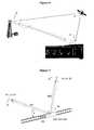
- is a schematic view of an exemplary outdoor hotspot binding scene where a serving cell and a repeater both are coupled via directional antennas.
- FIG. 4
- shows an exemplary wireless communication network comprising in a multi-hop configuration a multiple of repeaters with directional antennas.
- FIG. 5
- is a schematic view of an exemplary stationary shielded cell binding scene, where an indoor repeater is coupled with a directional antenna to an outdoor serving cell and transceives signals to an indoor DAS.
- FIG. 6
- is a schematic view of an exemplary mobile binding scene, where an on-train repeater is coupled with a directional antenna to a stationary outdoor serving cell and transceives signals to in-train cells.
- FIG. 7
- is a schematic view of an exemplary mobile binding scene explaining the handover between two stationary outdoor serving cells.
- As depicted in
Figure 1 wireless coverage is often provided by aRF repeater 1, that receives down-link signals in at least one frequency range from one or more BTS's or other repeaters 2 n itsdonor side 3 via adonor antenna 4. The at least one signal is filtered, amplified, and then retransmited to users orother repeaters 5 on itscoverage side 6 via thecoverage antenna 7. The complementary function is performed in the uplink direction, i.e. receiving at least one signal from at least one mobile user orother repeater 5 on thecoverage side 6, amplifying, filtering the signal, and transmitting it back to the serving BTS or repeater on thedonor side 3. For adjusting and controlling the repeater's transceiving parameters, like the gain or the filtering characteristics, therepeater 1 usually is equipped with acontrol unit 8. Thiscontrol unit 8 could interface to asignal measurement device 9, where signal quality parameters are derived from at least one received signal. For remote control or information exchange thecontrol unit 8 could be connected to an external orinternal modem 10. To obtain location related information thecontrol unit 8 may be connected to an external orinternal navigation system 11 as well. Therepeater 1 further may comprise a donorantenna control unit 12 and acoverage control unit 13. It should be noted that therepeater 1 in all or just one band could be attached to the serving BTS orrepeater 2 on thedonor side 3 by awired donor connection 14 as well. This concept in the following is referred to as a donor repeater. In many cases, on the coverage side, therepeater 1 in at least one frequency band is attached via awired coverage connection 15 to a distributedantenna system DAS 16. - According to
Figure 2 , antennas mostly used in indoor and mobile pick-up applications usually show vertical omni-directional antenna patterns 17. For a BTS signal distribution, sectorized (e.g. 120 °)antennas 18 are typically used. For dedicated links like a repeater-BTS connection adirectional antenna 19 can be used for directing the power transmission or reception in thehorizontal plane 19a and/orvertical plane 19b. A typical beam pattern of adirectional antenna 19 is drawn. - When a base station (BTS) 20 and a
repeater 21 are both installed in fixed stationary locations as shown inFigure 3 , staticdirectional antennas 19 are often used to enhance the link quality between thebase station 20 andrepeater 21. This also enhances isolation between thedonor beam 22 and thecoverage area 23 of therepeater 21. - The idea disclosed in this context realizes that directional antennas become more interesting at higher transmitted frequencies due to the fact that the dimensions needed to achieve a high directivity shrink as frequencies increase. According to
equation 1, the gain (G) of an antenna further is proportional to the square of the ratio of the aperture diameter (D) above of the wavelength (λ):
- The increased path loss insofar can be compensated by the use of high directional antennas at both ends of the radio link. However a disadvantage with respect to a mobile user is that in the same way the gain increases with the frequency that the angleϕ of the beam is decreasing according to
equation 3.
- As a consequence, the characteristics of the antenna, pointing towards the other end of the radio link, would have to be adjusted with an increased accuracy, which especially on a hand-held mobile device would result in a lot of effort and cost. However, this disadvantage can be turned into an advantage in repeater applications. By installing antennas with an adjustable pattern, the coverage area can be shaped in the vertical and horizontal plane. As depicted in
Figure 3 this could be used to enhance the frequency re-use factor. - High antenna directivity can be used to bridge a
re-use area 24. Inevitable side lobs 25, causing interference in there-use area 24, can be controlled by a careful antenna alignment (e.g. beam pattern nulling), by their design and by selecting an appropriate installation location. Hidden node locations (behind a building, a hill, etc.), usually seen as a problem in wireless networking, can effectively be utilized. It is therefore one aspect of the idea disclosed to adjust the beam pattern characteristics of anadjustable antenna 19 based on the current location data of therepeater 21, particularly on the current geographic data of therepeater 21. - For the same reason the isolation between the
donor beam 22 and thecoverage area 23 is increased by adjusting the beam pattern of theantenna 19 of therepeater 21 respectively. Acoverage area 26 can be reused for the same frequencies. Thecoverage area 26 might be shapeable by using antennas with an adjustable tilt angle (mechanical or electrical). Accordingly the cell size and the location of the handover zones might be formable. Instead of a "simple" antenna as shown an outdoor distributedantenna system DAS 16 could be attached on the coverage side. - It is further advantageous to distribute the signal to
several repeaters Figure 4 , which depicts a multi-hop configuration of a multiple ofrepeaters repeaters destination coverage area 28 via a multi-hop repeater network, when knowing the current location of each repeater. For this approach, at least the donor as well as the coverage side ofrepeaters Repeaters repeater exemplary repeater 29, the traffic could be routed via therepeater 30. In case of too much interference (side lobes) being caused in there-use area 31, the traffic might be routed viarepeaters re-use area 31 becoming connected to the inter-connect link, it might be also advantageous to transmit the signals in reverse frequency position. - According to another embodiment each repeater is equipped with a spectrum analyzer (functionality), permanently scanning in its location area for other users (e.g. primary user) and reporting the results to a central cognitive or auction based data base, as it is discussed inY. Zhang, et al., "Auction-Based Resource Allocation in Cognitive Radio Systems", IEEE Communications Magazine, November 2012, pp. 108 - 129. In return, the repeater shall be able to request part of the available spectrum for its own use from the data base.
- Due to field strength restrictions in many countries, the maximum equivalent Isotropically radiated power (EIRP) might be subjected to severe restrictions. This has to be considered when using high gain antennas in conjunction with high power BTS's. Since the antenna gains on both sides of a radio link can be summed, the best performance is obtained with directional antennas on both ends. However in case the EIRP limit is exceeded in one location, the gain on the other side can still be utilized.
- It is further mentioned that multiple streams (MIMO) pointing to one location as well as pointing to different locations (Coordinated Multi Point - CoMP) can be also optimized with adjustable antenna patterns and with a multi-beam approach as well. In this respect it may be beneficial to exploit polarization effects by adjusting the oscillation plane of the electric field component. This may be performed by the mechanical tilting of several antennas or could be done by weighting the parameters of an antenna array. Especially for optimally utilizing the spatial diversity effect it has been shown that optimizing the polarization for several spatial streams individually, the data throughput can be increased, as it is shown inBraz, O., et al., "LTE amplify and forward relay for indoor coverage extension",.
- According to yet another embodiment of the idea disclosed a
repeater 21 equipped with anadjustable antenna 36 can be applied to provide radio coverage in a shielded area as it is shown inFigure 5 . Basically the same as mentioned toFigure 3 applies. Favorably the additional penetration loss can be utilized to reduce the interference from insidearea 39 tooutside area 40 and thus there-use area 40 can be enlarged. Instead of aDAS 38 shown inFigure 5 , a single indoor antenna might be used. TheDAS 38 might be passive (e.g. coax. cable) or active (e.g. radio over fiber). Knowing the location of therepeater 21 allows a careful alignment of thebeam pattern 22 of thesmart antenna 36. - For moving shielded cells, like trains, buses, cars or trucks etc., as depicted in
Figures 6 and 7 it might be advantageous to utilize the current GPS location data provided viasatellite 41. Knowing the location of thedonor site 42 and the location of the moving shielded cell's pick upantenna 43, both antennas can be mechanically or electrically adjusted respectively with the goal to pointing exactly to each other, i.e. along the LOS. Particularly, the moving location of themobile repeater 21 is reported back to the donor site. Additionally, a RSSI monitoring helps to align the beam patterns in case of NLOS. A GPS based beam steering effectively could improve the SNIR. As shown inFigures 6 and Figure 7 by focusing the transmit power or bundling the receive power (in advance) into an a-priori known direction will improve the link balance. - Directional antennas at both ends of the radio link may be the best solution to obtain the maximum benefit. To be able to steer the
BTS antenna mobile antenna directional antennas BTS site 42. This approach would provide two advantages. The BTS could take care about its primary users in its own coverage cell. Secondly the repeater, usually operating at lower RF power, could implement beam steering without violating the EIRP requirements. - Not all communication services and/or operators might be located at the same mast/location. Knowing their location (in particular their geographical location) and their carrier frequencies, multiple beams could also be established optimizing the SNIR for each service individually. A schematic drawing is depicted in
Figure 7 . By monitoring the change in length over time of the vectors pointing from themobile vehicle 44 towards the BTS(s) 45, 46 for each service, showing at angles α(t) and β(t) respectively, the relative speed between the vehicle and its repeater and therespective BTS mobile vehicle 44 is approaching theBTS 45 the incoming signal frequency has to be shifted down and the outgoing signal frequency has to be shifted up. When departing fromBTS 46 signal shifting has to be applied the other way around. - For load balancing reasons it may be advantageous to separate the down-link traffic from the up-link traffic, i.e. routing the signals to different locations. Assuming
BTS 45 to be fully loaded with up-link traffic with smart antennas it may be possible to direct the up-link traffic toBTS 46 and vice-versa. - So far line of sight (LOS) aspects has been taken into account. It should be noted that in case of non line of sight (NLOS) conditions, the direct vector towards a BTS might not be the best choice for the communication link. To avoid complex beam forming algorithms for these scenarios, e.g. inside a tunnel, data obtained during calibration test might be stored in location (of the repeater) related look up tables.
- Interpreting the two BTS's 45, 46 as depicted in
Figure 7 as belonging to one service, e.g. two adjacent cells, it is obvious how the handover could be enhanced. At a certain location the antenna beam(s) is switched from one servingcell 46 to the next servingcell 45. - The used repeater can be an amplify-and-forward as well as a decode-and-forward type. It is neither limited to an on-frequency nor to a frequency shifting type. The shown donor and coverage links can comprise multiple antennas for MIMO streams with or without different polarizations. The radio link can be a line-of-sight (LOS) or a non-line-of-sight (NLOS) connection. Any communication standard (2G, 3G, 4G) and any duplex mode (FDD or TDD) can be used.
- To improve the performance of repeater systems, the idea disclosed utilizes steerable directional antennas. Antenna steering could be realized mechanically or electronically. The antenna gain could be achieved by multiple antenna elements or any other aperture based structure, e.g. dish antenna. By utilizing a large aperture or combining the responses of individual antenna elements of an array, a narrow beam can be formed with substantially increasing the gain in the desired direction and decreasing the gain in the remaining directions. This has the benefit of increasing the SNIR by increasing the signal level of the desired signal and reducing the signal level of the interfering signals.
- The use of an antenna array has additionally the following beneficial features. When the combining of the antenna responses is done digitally, several beams can be formed which could, for example, be used to enhancing the RF link between multiple bases stations simultaneously. With the appropriate RF hardware, a single antenna array could be used to generate separate beam for uplink and downlink simultaneously. In addition to steering a beam in the direction that enhances the reception of the desired signal, a null can be formed to reject the signal from an interfering source when digital combining of the antenna responses is utilized. A null has significantly more rejection than would be possible with a conventional directional antenna and can offer significant SINR increases over beam steering alone. With the antenna array signal processing being performed digitally, the array pattern can be adapted very quickly to facility the rapidly changing location for the mobile repeater system. An antenna array supports space-time processing used in MIMO systems. Individual beams for each type of wireless airinterface standards can be formed.
- For the above reasons along with cost and reliability concerns, it is envisioned that the array signal processing could be performed digitally. The idea disclosed however is not restricted to such an embodiment.
- Beam forming is a well-developed technology that has been in use for many years, and any number of algorithms could be used in this idea disclosed. One implementation could use blind beam forming, where the algorithm is able to steer the beam based on the signal characteristics of the received signal. As an alternative to a blind adaptive beam former, a directed beam former could be used. In this case, the bearing angle between the antenna array and the base station is determined and then a beam is directed in this direction. There are several methods for determining the bearing angle two of which are described below.
- The bearing angle can be determined by using a direction finding algorithm. Direction finding is a robust algorithm that determines the bearing angle of a signal impinging on an array using only the received signals but without specific knowledge of the signal types.
- Alternatively or even additionally, the bearing angle can be computed from the geographic location of the repeater, the geographic location of the base station and the spatial orientation of the antenna array. The geographic location of the repeater can be determined by a variety of techniques such as GPS, Inertial Navigation System (INS) and others. The spatial orientation of the antenna can be determined, for example, through the use of INS or a digital compass and the location of the antenna in the vehicle. Finally, the location of a target base station can be determined by decoding coordinates which are transmitted by the base station or decode identifying information transmitted by the base station and then determine the location from a database containing the geographic coordinates corresponding to this information. It can also use the current location of the repeater to index into a database to find the locations of base stations within the range of the repeater.
- As a variation on the second method, the geographic location of the base station could be determine by defining a set of geographic areas (zones), in which each geographic area would have one or more target base stations and their geographic coordinates. When the repeater was in a particular zone, a beam to each identified (predetermined) base station would be formed based on the location of the repeater and the base station. This beam would move to track the base station as the repeater moved. When the repeater crosses from one zone to the next, the beam could be directed to the new target cell, or it could bring up a second beam, where the gain of the second beam was increased and the first beam was decreased to facilitate the handoff of any calls in progress while moving between the two base stations. Another method that can work in some cases is to widen the beam so both base stations can hear the UL signals. This process could take place independently in multiple bands and within a band (different beams could be directed to different base stations).
- Additionally, the repeater could steer two beams to two base stations using the same spectrum. This would be treated as two different sectors by the repeater, and could be retransmitted on the mobile side to two different antennas. If the repeater was driving a DAS system, the DAS could treat these as separate sectors and send each sector to two different sets of remote antennas, each using the same spectrum. This could be done for multiple base stations. This process can be done independently in different bands, and different subsets of each band. Typically this would be done for each licensed operator. This could also be accomplished.
- In addition to receiving signals from base stations, steerable antennas can allow better isolation between the donor-side antennas and mobile-side antenna. This can be accomplished by adjusting the beam so the path loss between the two antennas is increased.
- Repeaters are referred to in this disclosure, but this should be understood to include all types of RF distribution equipment that use off-the-air pickup from base stations or other devices, including distributed antenna systems that use off-air pickup.


Claims (15)
- A repeater (1, 21, 29, 30, 32, 33, 34) for a wireless communication network, the repeater (1, 21, 29, 30, 32, 33, 34) comprising a donor side (3), a coverage side (6), a control unit (8, 11, 12) and a signal line between the donor side (3) and the coverage side (6) for repeating a downlink-signal from the donor side (3) to the coverage side (6) and for repeating an uplink-signal from the coverage side (6) to the donor side (3), wherein at least at one of the donor side (3) and the coverage side (6) the signal line is coupled with an adaptive antenna (19, 23, 36, 43), wherein at least one of the beam pattern characteristics of the at least one antenna (19, 23, 36, 43) is adjustable, and wherein the control unit (8, 11,12) is configured to adjust the at least one adjustable beam pattern characteristic of the antenna (19, 23, 36, 43) based on location data of the repeater (1, 21, 29, 30, 32, 33, 34).
- A repeater (1, 21, 29, 30, 32, 33, 34) according to claim 1,
wherein the at least one antenna (19, 23, 36, 43) is an adaptive directional antenna and wherein at least the angle beam pattern characteristic (6) of the at least one antenna (19, 23, 36, 43) is adjustable. - A repeater (1, 21, 29, 30, 32, 33, 34) according to claim 1 or 2,
further comprising signal quality measurement means (9) for indicating the signal quality of at least one received signal, wherein the control unit (8, 11,12) is further configured to adjust the at least one of the beam pattern characteristics of the at least one antenna (19, 23, 36, 43) based on the indicated signal quality of the at least one received signal. - A repeater (1, 21, 29, 30, 32, 33, 34) according to any of the preceding claims,
further being designed to be connected to a navigation system sensor, wherein the location data of the repeater are current location data derived from the navigation system sensor. - A repeater (1, 21, 29, 30, 32, 33, 34) according to claim 3 or 4 ,further comprising a modem interface port, where the control unit (8, 11,12) being further configured to provide the indicated signal quality and/or the current location data of the repeater (1, 21, 29, 30, 32, 33, 34) to a database.
- A repeater (1, 21, 29, 30, 32, 33, 34) according to any of the preceding claims, the repeater (1, 21, 29, 30, 32, 33, 34) being further configured to receive adjustment information for the at least one of the beam pattern characteristics of the at least one antenna (19, 23, 36, 43) from a database, the received adjustment information being responsive to the location data of the repeater.
- A repeater (1, 21, 29, 30, 32, 33, 34) any of the preceding claims, further comprising a frequency shifting means for shifting the frequency of the repeated signal on instruction.
- A repeater (1, 21, 29, 30, 32, 33, 34) according to any of the preceding claims, further comprising means for calculating a distance and/or the direction of at least one donor (20, 42) emitting the received down-link signal or receiving the emitted up-link signal and/or at least one user (5) emitting the received up-link signal or receiving the emitted down-link signal in relation to the repeater (1, 21, 29, 30, 32, 33, 34) based on location data of the at least one donor (20, 42) and based on the current loction data of the repeater (1, 21, 29, 30, 32, 33, 34), wherein the means are coupled with the control unit (8, 11,12), and wherein the control unit (8, 11,12) is configured to adjust the at least one of the beam pattern characteristics of the at least one antenna (19, 36) based on the calculated distance and/or based on the calculated direction.
- A repeater (1, 21, 29, 30, 32, 33, 34) according to claim 8,
wherein the control unit (8, 11,12) is further configured to compare a multiple of calculated distances and/or a multiple of calculated directions relative to a multiple of donors (20, 42, 45, 46) and/or users (5) and to adjust the at least one of the beam pattern characteristics of the at least one antenna (19, 36) in advance to an awaited next donor (20, 42, 45, 46) and/or user (5), thereby improving the handover between different donors (20, 42, 45, 46) and/or users (5). - A repeater (1, 21, 29, 30, 32, 33, 34) according to any of the preceding claims, wherein as the at least one antenna a multiple beam antenna, in particular an antenna array, is comprised.
- A repeater (1, 21, 29, 30, 32, 33, 34) according to claim 10,
wherein the control unit (8, 11,12) is further configured to adjust the at least one adjustable beam pattern characteristic of the multiple beam antenna for each of the multiple beams separately. - A wireless communication network comprising at least one repeater (21, 29, 30, 32, 33, 34) according to any of the preceding claims and a base station (20, 42, 45, 46), wherein the base station (20, 42, 45, 46) comprises a third adaptive antenna (35) for receiving the uplink-signal from the repeater (1, 21, 29, 30, 32, 33, 34) and/or for emitting the downlink-signal to the repeater (1, 21, 29, 30, 32, 33, 34), wherein at least one of the beam pattern characteristics of the third antenna (35) is adjustable, and wherein the base station (20, 42, 45, 46) is configured to receive the location data of the repeater (1, 21, 29, 30, 32, 33, 34) and to adjust the at least one adjustable beam pattern characteristic of the third antenna (35) based on the location data of the repeater (1 21, 29, 30, 32, 33, 34).
- A wireless communication network according to claim 12, wherein the base station (20, 42, 45, 46) is connected to a donor repeater (2) comprising an adaptive antenna (35) for receiving the uplink-signal from the repeater (1, 21, 29, 30, 32, 33, 34) and/or for emitting the downlink-signal to the repeater (1, 21, 29, 30, 32, 33, 34), wherein at least one of the beam pattern characteristics of the adaptive antenna (35) of the donor repeater (2) is adjustable, and wherein the donor repeater (2) is configured to receive the location data of the repeater (1, 21, 29, 30, 32, 33, 34) and to adjust the at least one adjustable beam pattern characteristic of the adaptive antenna (35) of the donor repater (2) based on the location data of the repeater (1, 21, 29, 30, 32, 33, 34).
- A wireless communication network comprising in a multi-hop configuration a multiple of repeaters (1, 21, 29, 30, 32, 33, 34), having the signal line coupled at the donor side (3) with a first adaptive antenna (20, 36) and coupled at the coverage side (6) with a second adaptive antenna according to any of claims 1 to 11.
- A wireless communication network comprising in a cognitive radio configuration a multiple of repeaters (1, 21, 29, 30, 32, 33, 34), having the signal line coupled at the donor side (3) with a first adaptive antenna (20, 36) and coupled at the coverage side (6) with a second adaptive antenna according to any of claims 1 to 11.
Priority Applications (2)
| Application Number | Priority Date | Filing Date | Title |
|---|---|---|---|
| EP13002430.0AEP2802089B1 (en) | 2013-05-07 | 2013-05-07 | Repeater for a wireless communication network |
| EP19158708.8AEP3512120A1 (en) | 2013-05-07 | 2013-05-07 | Repeater for a wireless communication network |
Applications Claiming Priority (1)
| Application Number | Priority Date | Filing Date | Title |
|---|---|---|---|
| EP13002430.0AEP2802089B1 (en) | 2013-05-07 | 2013-05-07 | Repeater for a wireless communication network |
Related Child Applications (1)
| Application Number | Title | Priority Date | Filing Date |
|---|---|---|---|
| EP19158708.8ADivisionEP3512120A1 (en) | 2013-05-07 | 2013-05-07 | Repeater for a wireless communication network |
Publications (2)
| Publication Number | Publication Date |
|---|---|
| EP2802089A1true EP2802089A1 (en) | 2014-11-12 |
| EP2802089B1 EP2802089B1 (en) | 2019-02-27 |
Family
ID=48366103
Family Applications (2)
| Application Number | Title | Priority Date | Filing Date |
|---|---|---|---|
| EP19158708.8AWithdrawnEP3512120A1 (en) | 2013-05-07 | 2013-05-07 | Repeater for a wireless communication network |
| EP13002430.0AActiveEP2802089B1 (en) | 2013-05-07 | 2013-05-07 | Repeater for a wireless communication network |
Family Applications Before (1)
| Application Number | Title | Priority Date | Filing Date |
|---|---|---|---|
| EP19158708.8AWithdrawnEP3512120A1 (en) | 2013-05-07 | 2013-05-07 | Repeater for a wireless communication network |
Country Status (1)
| Country | Link |
|---|---|
| EP (2) | EP3512120A1 (en) |
Cited By (12)
| Publication number | Priority date | Publication date | Assignee | Title |
|---|---|---|---|---|
| WO2016118795A1 (en)* | 2015-01-23 | 2016-07-28 | Microsoft Technology Licensing, Llc | Wireless connectivity using white spaces |
| JP2016174318A (en)* | 2015-03-18 | 2016-09-29 | 株式会社国際電気通信基礎技術研究所 | Digital radio transmission apparatus and digital radio communication system |
| US9780853B2 (en) | 2016-02-19 | 2017-10-03 | Elwha Llc | Receiver configured to provide a channel capacity that exceeds a saturation channel capacity |
| US9800310B2 (en)* | 2016-02-19 | 2017-10-24 | Elwha Llc | Transmitter configured to provide a channel capacity that exceeds a saturation channel capacity |
| WO2018132499A1 (en)* | 2017-01-10 | 2018-07-19 | Nextivity, Inc. | Managing the beam direction of the donor antenna of a mobile repeater |
| US10236955B2 (en) | 2016-02-19 | 2019-03-19 | Elwha Llc | System with transmitter and receiver remote from one another and configured to provide a channel capacity that exceeds a saturation channel capacity |
| US10236947B2 (en) | 2016-02-19 | 2019-03-19 | Elwha Llc | System with transmitter and receiver configured to provide a channel capacity that exceeds a saturation channel capacity |
| US10461825B2 (en) | 2016-12-23 | 2019-10-29 | Commscope Technologies Llc | Distributed MIMO and/or transmit diversity in a cloud-ran system |
| CN113286366A (en)* | 2020-02-20 | 2021-08-20 | 上海华为技术有限公司 | Beam management method, beam management system and related equipment |
| WO2022247832A1 (en)* | 2021-05-25 | 2022-12-01 | 维沃移动通信有限公司 | Wireless communication method, apparatus and device |
| US20230119096A1 (en)* | 2021-10-15 | 2023-04-20 | Nokia Technologies Oy | Multiple donor supported directional repeater |
| US12224837B2 (en)* | 2021-04-19 | 2025-02-11 | Outdoor Wireless Networks LLC | Systems and methods for reconfigurable repeaters for wireless telecommunications |
Families Citing this family (2)
| Publication number | Priority date | Publication date | Assignee | Title |
|---|---|---|---|---|
| WO2020102752A1 (en) | 2018-11-16 | 2020-05-22 | Commscope Technologies Llc | Interference suppression for multi-user multiple-input-multiple-output (mu-mimo) pre-coders using coordination among one or more radio points |
| US20250286605A1 (en)* | 2024-03-11 | 2025-09-11 | Dimitris Kolokotronis | Active antenna system for radio terminal device |
Citations (6)
| Publication number | Priority date | Publication date | Assignee | Title |
|---|---|---|---|---|
| US6642894B1 (en)* | 1999-09-13 | 2003-11-04 | Motorola, Inc. | Smart antenna for airborne cellular system |
| US20080225931A1 (en) | 2007-03-02 | 2008-09-18 | Qualcomm Incorporated | Use of Adaptive Antenna Array in Conjunction with an On-Channel Repeater to Improve Signal Quality |
| US20090079631A1 (en)* | 2002-04-27 | 2009-03-26 | Eads Deutschland Gmbh | Method for data exchange between military aircraft and device for carrying out this method |
| US20100234071A1 (en) | 2009-03-12 | 2010-09-16 | Comsys Communication & Signal Processing Ltd. | Vehicle integrated communications system |
| US20100284446A1 (en) | 2009-05-06 | 2010-11-11 | Fenghao Mu | Method and Apparatus for MIMO Repeater Chains in a Wireless Communication Network |
| US20100297937A1 (en)* | 2007-11-06 | 2010-11-25 | Kmw Inc. | Mobile Communication Repeating Method in Moving Object and Repeater Thereof |
Family Cites Families (3)
| Publication number | Priority date | Publication date | Assignee | Title |
|---|---|---|---|---|
| US6009124A (en)* | 1997-09-22 | 1999-12-28 | Intel Corporation | High data rate communications network employing an adaptive sectored antenna |
| JP5453875B2 (en)* | 2009-03-27 | 2014-03-26 | 富士通株式会社 | RELAY DEVICE, RELAY METHOD, RECEPTION DEVICE, AND RECEPTION METHOD |
| WO2013058673A1 (en)* | 2011-10-20 | 2013-04-25 | Limited Liability Company "Radio Gigabit" | System and method of relay communication with electronic beam adjustment |
- 2013
- 2013-05-07EPEP19158708.8Apatent/EP3512120A1/ennot_activeWithdrawn
- 2013-05-07EPEP13002430.0Apatent/EP2802089B1/enactiveActive
Patent Citations (6)
| Publication number | Priority date | Publication date | Assignee | Title |
|---|---|---|---|---|
| US6642894B1 (en)* | 1999-09-13 | 2003-11-04 | Motorola, Inc. | Smart antenna for airborne cellular system |
| US20090079631A1 (en)* | 2002-04-27 | 2009-03-26 | Eads Deutschland Gmbh | Method for data exchange between military aircraft and device for carrying out this method |
| US20080225931A1 (en) | 2007-03-02 | 2008-09-18 | Qualcomm Incorporated | Use of Adaptive Antenna Array in Conjunction with an On-Channel Repeater to Improve Signal Quality |
| US20100297937A1 (en)* | 2007-11-06 | 2010-11-25 | Kmw Inc. | Mobile Communication Repeating Method in Moving Object and Repeater Thereof |
| US20100234071A1 (en) | 2009-03-12 | 2010-09-16 | Comsys Communication & Signal Processing Ltd. | Vehicle integrated communications system |
| US20100284446A1 (en) | 2009-05-06 | 2010-11-11 | Fenghao Mu | Method and Apparatus for MIMO Repeater Chains in a Wireless Communication Network |
Non-Patent Citations (6)
| Title |
|---|
| ANDERS FURUSKAR; SARA MAZUR; FRANK MUIIER; HAKAN OLOFSSON: "EDGE; Enhanced data rates for GSM and TDMA/136 evolution", IEEE PERSONAL COMMUNICATIONS, vol. 6, June 1999 (1999-06-01), pages 56 - 66 |
| BRAZ, 0. ET AL.: "LTE amplify and forward relay for Indoor coverage extension", FUNKSCHAU HEFT, vol. 7, April 2009 (2009-04-01) |
| G. J. FOSCHLNI; M. J. GANS: "On limits of wireless communications in a fading environment when using multiple antennas", WIRELESS PERSONAL COMMUNICATION, vol. 6, March 1998 (1998-03-01), pages 311 - 335 |
| M. MUCK ET AL.: "ETSI reconfigurable radio systems: status and future directions on software defined radio and cognitive radio standards", IEEE COMMUNICATIONS MAGAZINE, September 2010 (2010-09-01), pages 78 - 86 |
| S. CATREUX ET AL.: "Adaptive Modulation and MIMO Coding for Broadband Wireless Data Networks", IEEE COMMUNICATIONS MAGAZINE, June 2002 (2002-06-01), pages 108 - 115 |
| Y. ZHANG ET AL.: "Auction-Based Resource Allocation in Cognitive Radio Systems", IEEE COMMUNICATIONS MAGAZINE, November 2012 (2012-11-01), pages 108 - 129 |
Cited By (13)
| Publication number | Priority date | Publication date | Assignee | Title |
|---|---|---|---|---|
| WO2016118795A1 (en)* | 2015-01-23 | 2016-07-28 | Microsoft Technology Licensing, Llc | Wireless connectivity using white spaces |
| JP2016174318A (en)* | 2015-03-18 | 2016-09-29 | 株式会社国際電気通信基礎技術研究所 | Digital radio transmission apparatus and digital radio communication system |
| US10236947B2 (en) | 2016-02-19 | 2019-03-19 | Elwha Llc | System with transmitter and receiver configured to provide a channel capacity that exceeds a saturation channel capacity |
| US9800310B2 (en)* | 2016-02-19 | 2017-10-24 | Elwha Llc | Transmitter configured to provide a channel capacity that exceeds a saturation channel capacity |
| US10236955B2 (en) | 2016-02-19 | 2019-03-19 | Elwha Llc | System with transmitter and receiver remote from one another and configured to provide a channel capacity that exceeds a saturation channel capacity |
| US9780853B2 (en) | 2016-02-19 | 2017-10-03 | Elwha Llc | Receiver configured to provide a channel capacity that exceeds a saturation channel capacity |
| US10461825B2 (en) | 2016-12-23 | 2019-10-29 | Commscope Technologies Llc | Distributed MIMO and/or transmit diversity in a cloud-ran system |
| WO2018132499A1 (en)* | 2017-01-10 | 2018-07-19 | Nextivity, Inc. | Managing the beam direction of the donor antenna of a mobile repeater |
| US10348393B2 (en) | 2017-01-10 | 2019-07-09 | Nextivity, Inc. | Managing the beam direction of the donor antenna of a mobile repeater |
| CN113286366A (en)* | 2020-02-20 | 2021-08-20 | 上海华为技术有限公司 | Beam management method, beam management system and related equipment |
| US12224837B2 (en)* | 2021-04-19 | 2025-02-11 | Outdoor Wireless Networks LLC | Systems and methods for reconfigurable repeaters for wireless telecommunications |
| WO2022247832A1 (en)* | 2021-05-25 | 2022-12-01 | 维沃移动通信有限公司 | Wireless communication method, apparatus and device |
| US20230119096A1 (en)* | 2021-10-15 | 2023-04-20 | Nokia Technologies Oy | Multiple donor supported directional repeater |
Also Published As
| Publication number | Publication date |
|---|---|
| EP3512120A1 (en) | 2019-07-17 |
| EP2802089B1 (en) | 2019-02-27 |
Similar Documents
| Publication | Publication Date | Title |
|---|---|---|
| EP2802089B1 (en) | Repeater for a wireless communication network | |
| KR101174727B1 (en) | Systems and method for providing in-flight broadband mobile communication services | |
| KR101517524B1 (en) | High data rate aircraft to ground communication antenna system | |
| US6735438B1 (en) | Antenna for air-to-ground communication | |
| US11146325B2 (en) | MIMO communication system for vehicles | |
| US7904085B2 (en) | Mobile device and radio interface arrangement method | |
| EP3057378B1 (en) | Wireless communications system, wireless mobile station, and wireless base station | |
| US12394883B2 (en) | Antenna system for vehicles | |
| US20160249233A1 (en) | Providing broadband service to trains | |
| CN109905150A (en) | Distributed wireless antennas and mmWave scanning repeaters | |
| EP0879507B1 (en) | Antenna arrangement | |
| JP2015501096A (en) | Interference mitigation techniques for air-to-ground systems | |
| EP2495882A1 (en) | Distributed antenna system | |
| EP3742626B1 (en) | Dynamic azimuth adjustment for cellular repeater antenna systems | |
| CN113573318B (en) | Spectrum use method, system, antenna and network equipment | |
| Cao et al. | Capacity enhancement for mmWave multi-beam satellite-terrestrial backhaul via beam sharing | |
| US8412125B2 (en) | Wireless communication system with transmit diversity designs | |
| KR100660141B1 (en) | Mobile satellite repeater and satellite repeater system using the same | |
| CA3074796A1 (en) | Electric train system with integrated communication system |
Legal Events
| Date | Code | Title | Description |
|---|---|---|---|
| PUAI | Public reference made under article 153(3) epc to a published international application that has entered the european phase | Free format text:ORIGINAL CODE: 0009012 | |
| 17P | Request for examination filed | Effective date:20140305 | |
| AK | Designated contracting states | Kind code of ref document:A1 Designated state(s):AL AT BE BG CH CY CZ DE DK EE ES FI FR GB GR HR HU IE IS IT LI LT LU LV MC MK MT NL NO PL PT RO RS SE SI SK SM TR | |
| AX | Request for extension of the european patent | Extension state:BA ME | |
| STAA | Information on the status of an ep patent application or granted ep patent | Free format text:STATUS: EXAMINATION IS IN PROGRESS | |
| 17Q | First examination report despatched | Effective date:20170118 | |
| GRAP | Despatch of communication of intention to grant a patent | Free format text:ORIGINAL CODE: EPIDOSNIGR1 | |
| STAA | Information on the status of an ep patent application or granted ep patent | Free format text:STATUS: GRANT OF PATENT IS INTENDED | |
| INTG | Intention to grant announced | Effective date:20180920 | |
| GRAS | Grant fee paid | Free format text:ORIGINAL CODE: EPIDOSNIGR3 | |
| GRAA | (expected) grant | Free format text:ORIGINAL CODE: 0009210 | |
| STAA | Information on the status of an ep patent application or granted ep patent | Free format text:STATUS: THE PATENT HAS BEEN GRANTED | |
| AK | Designated contracting states | Kind code of ref document:B1 Designated state(s):AL AT BE BG CH CY CZ DE DK EE ES FI FR GB GR HR HU IE IS IT LI LT LU LV MC MK MT NL NO PL PT RO RS SE SI SK SM TR | |
| REG | Reference to a national code | Ref country code:GB Ref legal event code:FG4D | |
| REG | Reference to a national code | Ref country code:CH Ref legal event code:EP | |
| REG | Reference to a national code | Ref country code:DE Ref legal event code:R096 Ref document number:602013051275 Country of ref document:DE | |
| REG | Reference to a national code | Ref country code:AT Ref legal event code:REF Ref document number:1102852 Country of ref document:AT Kind code of ref document:T Effective date:20190315 | |
| REG | Reference to a national code | Ref country code:IE Ref legal event code:FG4D | |
| REG | Reference to a national code | Ref country code:NL Ref legal event code:FP | |
| REG | Reference to a national code | Ref country code:LT Ref legal event code:MG4D | |
| PG25 | Lapsed in a contracting state [announced via postgrant information from national office to epo] | Ref country code:FI Free format text:LAPSE BECAUSE OF FAILURE TO SUBMIT A TRANSLATION OF THE DESCRIPTION OR TO PAY THE FEE WITHIN THE PRESCRIBED TIME-LIMIT Effective date:20190227 Ref country code:SE Free format text:LAPSE BECAUSE OF FAILURE TO SUBMIT A TRANSLATION OF THE DESCRIPTION OR TO PAY THE FEE WITHIN THE PRESCRIBED TIME-LIMIT Effective date:20190227 Ref country code:NO Free format text:LAPSE BECAUSE OF FAILURE TO SUBMIT A TRANSLATION OF THE DESCRIPTION OR TO PAY THE FEE WITHIN THE PRESCRIBED TIME-LIMIT Effective date:20190527 Ref country code:PT Free format text:LAPSE BECAUSE OF FAILURE TO SUBMIT A TRANSLATION OF THE DESCRIPTION OR TO PAY THE FEE WITHIN THE PRESCRIBED TIME-LIMIT Effective date:20190627 Ref country code:LT Free format text:LAPSE BECAUSE OF FAILURE TO SUBMIT A TRANSLATION OF THE DESCRIPTION OR TO PAY THE FEE WITHIN THE PRESCRIBED TIME-LIMIT Effective date:20190227 | |
| PG25 | Lapsed in a contracting state [announced via postgrant information from national office to epo] | Ref country code:RS Free format text:LAPSE BECAUSE OF FAILURE TO SUBMIT A TRANSLATION OF THE DESCRIPTION OR TO PAY THE FEE WITHIN THE PRESCRIBED TIME-LIMIT Effective date:20190227 Ref country code:BG Free format text:LAPSE BECAUSE OF FAILURE TO SUBMIT A TRANSLATION OF THE DESCRIPTION OR TO PAY THE FEE WITHIN THE PRESCRIBED TIME-LIMIT Effective date:20190527 Ref country code:HR Free format text:LAPSE BECAUSE OF FAILURE TO SUBMIT A TRANSLATION OF THE DESCRIPTION OR TO PAY THE FEE WITHIN THE PRESCRIBED TIME-LIMIT Effective date:20190227 Ref country code:GR Free format text:LAPSE BECAUSE OF FAILURE TO SUBMIT A TRANSLATION OF THE DESCRIPTION OR TO PAY THE FEE WITHIN THE PRESCRIBED TIME-LIMIT Effective date:20190528 Ref country code:LV Free format text:LAPSE BECAUSE OF FAILURE TO SUBMIT A TRANSLATION OF THE DESCRIPTION OR TO PAY THE FEE WITHIN THE PRESCRIBED TIME-LIMIT Effective date:20190227 Ref country code:IS Free format text:LAPSE BECAUSE OF FAILURE TO SUBMIT A TRANSLATION OF THE DESCRIPTION OR TO PAY THE FEE WITHIN THE PRESCRIBED TIME-LIMIT Effective date:20190627 | |
| REG | Reference to a national code | Ref country code:AT Ref legal event code:MK05 Ref document number:1102852 Country of ref document:AT Kind code of ref document:T Effective date:20190227 | |
| PG25 | Lapsed in a contracting state [announced via postgrant information from national office to epo] | Ref country code:AL Free format text:LAPSE BECAUSE OF FAILURE TO SUBMIT A TRANSLATION OF THE DESCRIPTION OR TO PAY THE FEE WITHIN THE PRESCRIBED TIME-LIMIT Effective date:20190227 Ref country code:EE Free format text:LAPSE BECAUSE OF FAILURE TO SUBMIT A TRANSLATION OF THE DESCRIPTION OR TO PAY THE FEE WITHIN THE PRESCRIBED TIME-LIMIT Effective date:20190227 Ref country code:DK Free format text:LAPSE BECAUSE OF FAILURE TO SUBMIT A TRANSLATION OF THE DESCRIPTION OR TO PAY THE FEE WITHIN THE PRESCRIBED TIME-LIMIT Effective date:20190227 Ref country code:RO Free format text:LAPSE BECAUSE OF FAILURE TO SUBMIT A TRANSLATION OF THE DESCRIPTION OR TO PAY THE FEE WITHIN THE PRESCRIBED TIME-LIMIT Effective date:20190227 Ref country code:CZ Free format text:LAPSE BECAUSE OF FAILURE TO SUBMIT A TRANSLATION OF THE DESCRIPTION OR TO PAY THE FEE WITHIN THE PRESCRIBED TIME-LIMIT Effective date:20190227 Ref country code:SK Free format text:LAPSE BECAUSE OF FAILURE TO SUBMIT A TRANSLATION OF THE DESCRIPTION OR TO PAY THE FEE WITHIN THE PRESCRIBED TIME-LIMIT Effective date:20190227 Ref country code:ES Free format text:LAPSE BECAUSE OF FAILURE TO SUBMIT A TRANSLATION OF THE DESCRIPTION OR TO PAY THE FEE WITHIN THE PRESCRIBED TIME-LIMIT Effective date:20190227 | |
| REG | Reference to a national code | Ref country code:DE Ref legal event code:R097 Ref document number:602013051275 Country of ref document:DE | |
| PG25 | Lapsed in a contracting state [announced via postgrant information from national office to epo] | Ref country code:SM Free format text:LAPSE BECAUSE OF FAILURE TO SUBMIT A TRANSLATION OF THE DESCRIPTION OR TO PAY THE FEE WITHIN THE PRESCRIBED TIME-LIMIT Effective date:20190227 Ref country code:PL Free format text:LAPSE BECAUSE OF FAILURE TO SUBMIT A TRANSLATION OF THE DESCRIPTION OR TO PAY THE FEE WITHIN THE PRESCRIBED TIME-LIMIT Effective date:20190227 | |
| REG | Reference to a national code | Ref country code:CH Ref legal event code:PL | |
| PG25 | Lapsed in a contracting state [announced via postgrant information from national office to epo] | Ref country code:AT Free format text:LAPSE BECAUSE OF FAILURE TO SUBMIT A TRANSLATION OF THE DESCRIPTION OR TO PAY THE FEE WITHIN THE PRESCRIBED TIME-LIMIT Effective date:20190227 | |
| PLBE | No opposition filed within time limit | Free format text:ORIGINAL CODE: 0009261 | |
| STAA | Information on the status of an ep patent application or granted ep patent | Free format text:STATUS: NO OPPOSITION FILED WITHIN TIME LIMIT | |
| GBPC | Gb: european patent ceased through non-payment of renewal fee | Effective date:20190527 | |
| PG25 | Lapsed in a contracting state [announced via postgrant information from national office to epo] | Ref country code:LI Free format text:LAPSE BECAUSE OF NON-PAYMENT OF DUE FEES Effective date:20190531 Ref country code:CH Free format text:LAPSE BECAUSE OF NON-PAYMENT OF DUE FEES Effective date:20190531 Ref country code:MC Free format text:LAPSE BECAUSE OF FAILURE TO SUBMIT A TRANSLATION OF THE DESCRIPTION OR TO PAY THE FEE WITHIN THE PRESCRIBED TIME-LIMIT Effective date:20190227 | |
| 26N | No opposition filed | Effective date:20191128 | |
| REG | Reference to a national code | Ref country code:BE Ref legal event code:MM Effective date:20190531 | |
| PG25 | Lapsed in a contracting state [announced via postgrant information from national office to epo] | Ref country code:SI Free format text:LAPSE BECAUSE OF FAILURE TO SUBMIT A TRANSLATION OF THE DESCRIPTION OR TO PAY THE FEE WITHIN THE PRESCRIBED TIME-LIMIT Effective date:20190227 Ref country code:LU Free format text:LAPSE BECAUSE OF NON-PAYMENT OF DUE FEES Effective date:20190507 | |
| PG25 | Lapsed in a contracting state [announced via postgrant information from national office to epo] | Ref country code:TR Free format text:LAPSE BECAUSE OF FAILURE TO SUBMIT A TRANSLATION OF THE DESCRIPTION OR TO PAY THE FEE WITHIN THE PRESCRIBED TIME-LIMIT Effective date:20190227 | |
| PG25 | Lapsed in a contracting state [announced via postgrant information from national office to epo] | Ref country code:IE Free format text:LAPSE BECAUSE OF NON-PAYMENT OF DUE FEES Effective date:20190507 Ref country code:GB Free format text:LAPSE BECAUSE OF NON-PAYMENT OF DUE FEES Effective date:20190527 | |
| PG25 | Lapsed in a contracting state [announced via postgrant information from national office to epo] | Ref country code:BE Free format text:LAPSE BECAUSE OF NON-PAYMENT OF DUE FEES Effective date:20190531 | |
| PG25 | Lapsed in a contracting state [announced via postgrant information from national office to epo] | Ref country code:CY Free format text:LAPSE BECAUSE OF FAILURE TO SUBMIT A TRANSLATION OF THE DESCRIPTION OR TO PAY THE FEE WITHIN THE PRESCRIBED TIME-LIMIT Effective date:20190227 | |
| PG25 | Lapsed in a contracting state [announced via postgrant information from national office to epo] | Ref country code:MT Free format text:LAPSE BECAUSE OF FAILURE TO SUBMIT A TRANSLATION OF THE DESCRIPTION OR TO PAY THE FEE WITHIN THE PRESCRIBED TIME-LIMIT Effective date:20190227 Ref country code:HU Free format text:LAPSE BECAUSE OF FAILURE TO SUBMIT A TRANSLATION OF THE DESCRIPTION OR TO PAY THE FEE WITHIN THE PRESCRIBED TIME-LIMIT; INVALID AB INITIO Effective date:20130507 | |
| PGFP | Annual fee paid to national office [announced via postgrant information from national office to epo] | Ref country code:NL Payment date:20210526 Year of fee payment:9 | |
| PG25 | Lapsed in a contracting state [announced via postgrant information from national office to epo] | Ref country code:MK Free format text:LAPSE BECAUSE OF FAILURE TO SUBMIT A TRANSLATION OF THE DESCRIPTION OR TO PAY THE FEE WITHIN THE PRESCRIBED TIME-LIMIT Effective date:20190227 | |
| REG | Reference to a national code | Ref country code:NL Ref legal event code:MM Effective date:20220601 | |
| PG25 | Lapsed in a contracting state [announced via postgrant information from national office to epo] | Ref country code:NL Free format text:LAPSE BECAUSE OF NON-PAYMENT OF DUE FEES Effective date:20220601 | |
| P01 | Opt-out of the competence of the unified patent court (upc) registered | Effective date:20230530 | |
| PGFP | Annual fee paid to national office [announced via postgrant information from national office to epo] | Ref country code:DE Payment date:20250529 Year of fee payment:13 | |
| PGFP | Annual fee paid to national office [announced via postgrant information from national office to epo] | Ref country code:IT Payment date:20250521 Year of fee payment:13 | |
| PGFP | Annual fee paid to national office [announced via postgrant information from national office to epo] | Ref country code:FR Payment date:20250526 Year of fee payment:13 |