EP2801231B1 - Wireless access point assignment - Google Patents
Wireless access point assignmentDownload PDFInfo
- Publication number
- EP2801231B1 EP2801231B1EP12864664.3AEP12864664AEP2801231B1EP 2801231 B1EP2801231 B1EP 2801231B1EP 12864664 AEP12864664 AEP 12864664AEP 2801231 B1EP2801231 B1EP 2801231B1
- Authority
- EP
- European Patent Office
- Prior art keywords
- wireless access
- access point
- client device
- network traffic
- network
- Prior art date
- Legal status (The legal status is an assumption and is not a legal conclusion. Google has not performed a legal analysis and makes no representation as to the accuracy of the status listed.)
- Active
Links
Images


Classifications
- H—ELECTRICITY
- H04—ELECTRIC COMMUNICATION TECHNIQUE
- H04W—WIRELESS COMMUNICATION NETWORKS
- H04W28/00—Network traffic management; Network resource management
- H04W28/02—Traffic management, e.g. flow control or congestion control
- H04W28/10—Flow control between communication endpoints
- H04W28/12—Flow control between communication endpoints using signalling between network elements
- H—ELECTRICITY
- H04—ELECTRIC COMMUNICATION TECHNIQUE
- H04W—WIRELESS COMMUNICATION NETWORKS
- H04W48/00—Access restriction; Network selection; Access point selection
- H04W48/20—Selecting an access point
- H—ELECTRICITY
- H04—ELECTRIC COMMUNICATION TECHNIQUE
- H04W—WIRELESS COMMUNICATION NETWORKS
- H04W28/00—Network traffic management; Network resource management
- H04W28/02—Traffic management, e.g. flow control or congestion control
- H04W28/08—Load balancing or load distribution
- H04W28/086—Load balancing or load distribution among access entities
- H04W28/0861—Load balancing or load distribution among access entities between base stations
- H—ELECTRICITY
- H04—ELECTRIC COMMUNICATION TECHNIQUE
- H04W—WIRELESS COMMUNICATION NETWORKS
- H04W72/00—Local resource management
- H04W72/20—Control channels or signalling for resource management
- H04W72/29—Control channels or signalling for resource management between an access point and the access point controlling device
- H—ELECTRICITY
- H04—ELECTRIC COMMUNICATION TECHNIQUE
- H04W—WIRELESS COMMUNICATION NETWORKS
- H04W28/00—Network traffic management; Network resource management
- H04W28/16—Central resource management; Negotiation of resources or communication parameters, e.g. negotiating bandwidth or QoS [Quality of Service]
- H—ELECTRICITY
- H04—ELECTRIC COMMUNICATION TECHNIQUE
- H04W—WIRELESS COMMUNICATION NETWORKS
- H04W72/00—Local resource management
- H04W72/50—Allocation or scheduling criteria for wireless resources
- H04W72/52—Allocation or scheduling criteria for wireless resources based on load
- H—ELECTRICITY
- H04—ELECTRIC COMMUNICATION TECHNIQUE
- H04W—WIRELESS COMMUNICATION NETWORKS
- H04W72/00—Local resource management
- H04W72/50—Allocation or scheduling criteria for wireless resources
- H04W72/56—Allocation or scheduling criteria for wireless resources based on priority criteria
- H—ELECTRICITY
- H04—ELECTRIC COMMUNICATION TECHNIQUE
- H04W—WIRELESS COMMUNICATION NETWORKS
- H04W88/00—Devices specially adapted for wireless communication networks, e.g. terminals, base stations or access point devices
- H04W88/08—Access point devices
Definitions
- Wireless networksallow client devices to wirelessly connect to wireless access points to receive network access.
- a central network controllermay control the wireless access points, for example, by selecting radio channels for transmission by the wireless access points.
- the central network controllermay control the network configuration, such as by determining which wireless access point a client device connects to.
- US 2007/0249291 A1discloses a wireless communication method in which the current state of an access terminal is monitored.
- US 2007/0217377 A1discloses a wireless communication method for access point selection.
- US 5,697,059discloses a system for dynamically allocating channels among base stations in a wireless communication system.
- a wireless networkmay involve client devices communicating wirelessly with a wireless access point to access a network.
- a network controllermay analyze network patterns, such as client device characteristics or traffic patterns, to determine how to configure wireless access points. For example, a network controller may determine which client devices to assign to a wireless access point and which radio channel to assign to a wireless access point.
- a network controllermay assign client devices to wireless access points based on the traffic patterns of the client devices. Client devices with greater traffic or a higher priority type of traffic may be assigned to a wireless access point likely to provide greater throughput to the client device than a client device previously associated with a lower amount of network traffic.
- client devicesmay be assigned to wireless access points based on the communication protocol use by the client devices. For example, client devices using an older wireless technology may connect to a different wireless access point than client devices communicating using a newer communication protocol. For example, client devices communicating using 802.11n may access a network through a first wireless access point and client devices communicating using 802.11a may access the network through a second wireless access point.
- a network controllermay analyze network traffic patterns associated with a wireless access point and assign a radio channel to the wireless access point based on the traffic patterns. For example, the radio channel may be selected to reduce co-channel interference and increase throughput for the wireless access point that has a greater level of traffic.
- the radio channelmay be assigned for a particular time period. For example, a first radio channel may be assigned to the wireless access point for Tuesdays, and a second radio channel may be assigned to the wireless access point for Saturdays.
- FIG. 1is a block diagram illustrating one example of a computing system 112.
- the computing system 112may be a network in which a central network controller determines which wireless access point to associate with a particular client device. For example, network traffic originating from the client devices may be analyzed to determine how to allocate the client devices among the wireless access points.
- the computing system 112may include an apparatus 100, a network 105, a wireless access point A 106, a wireless access point B 107, a client device 108, a client device 109, and a client device 110.
- the wireless access point A 106 and the wireless access point B 107may be any suitable wireless access points.
- the wireless access points A 106 and B 107may be used to provide wireless network access to client devices, such as by transmitting information wirelessly via radio frequencies to client devices 108, 109, and 110.
- the wireless access points A 106 and B 107may be combined with other network hardware, such as a router.
- the client devices 108, 109, and 110may be, for example, desktops, laptops, or mobile computing devices.
- the client device 108, 109, and 110may be client devices that wirelessly connect to the network 105.
- the client devices 108, 109, and 110may receive access to the network 105 via a wireless access point, such as wireless access point A 107 or wireless access point B 108.
- the wireless access points A 107 and B 108may wirelessly transmit data to the client devices associated with the wireless access points.
- wireless access point B 107may wirelessly transmit data to the client devices 108 and 109
- wireless access point A 106may wirelessly transmit data to the client device 110.
- the network 105may be, for example, the Internet or a Local Area Network (LAN).
- the network 105may be used to communicate information to the wireless access points A 106 and B 107 about which client devices they should associate with.
- the network 105may be a wired network for transmitting information to the wireless access points A 106 and B 107, and the wireless access points A 106 and 107 may wirelessly transmit the information to client devices.
- the apparatus 100may be any suitable apparatus for controlling network parameters.
- the apparatus 100may be a network controller, such as a wireless Local Area Network (LAN) controller, for centrally managing radio frequency power, channel, authentication, and security of wireless access points.
- the apparatus 100may determine which wireless access point to associate with a client device.
- the apparatus 100may include a transmitter 101, a wireless access point determiner 102, and a machine-readable storage medium 103.
- the wireless access point determiner 102may be, for example, a processor, such as a central processing unit (CPU), a semiconductor-based microprocessor, or any other device suitable for retrieval and execution of instructions.
- the wireless access point determiner 102includes logic instead of or in addition to a processor.
- the wireless access point determiner 102may include one or more integrated circuits (ICs) or other electronic circuits that comprise a plurality of electronic components for performing the functionality described below.
- the wireless access point determiner 102includes multiple processors. For example, one processor may perform some functionality and another processor may perform other functionality.
- the machine-readable storage medium 103may be any suitable machine readable medium, such as an electronic, magnetic, optical, or other physical storage device that stores executable instructions or other data (e.g., a hard disk drive, random access memory, flash memory, etc.).
- the machine-readable storage medium 103may be, for example, a computer readable non-transitory medium.
- the machine-readable storage medium 103may include client device network traffic data 104.
- the client device network traffic data 104may include data related to network traffic originating from each client device.
- the client device network traffic data 104may include information about time based traffic patterns related to, for example, a time of day or a day of the week.
- the machine-readable storage medium 103may include instructions 111 executable by the wireless access point determiner 102.
- the instructions 111may include instructions executable by the wireless access point determiner 102 to analyze the client device network traffic data 104 to determine which wireless access point to assign to a client device for network connectivity.
- the wireless access point determiner 102may use the client device network traffic data 104 to determine a wireless access point assignment for a client device likely to result in better throughput, such as by allocating client devices in a manner likely to more evenly distribute network traffic among wireless access points. For example, based on an analysis of the client device network traffic data 104, the wireless access point determiner 102 may assign client device 108 to wireless access point B 107.
- the transmitter 101may be, for example, a hardware component of the apparatus 100 for transmitting information via the network 105 to the wireless access points A 106 and B 107.
- the transmitter 101may transmit client device assignment information determined by the assignment determiner 102 to the wireless access points A 106 and B 107.
- the transmitter 101may transmit information to the wireless access point A 106 indicating that client device 108 and client device 109 is assigned to it, and wireless access point A 106 may connect to the client devices 108 and 109 when they attempt to connect to the network 105.
- Figure 2is a flow chart 200 illustrating one example of a method to assign a client device to a wireless access point based on stored network traffic data.
- network traffic history datamay be analyzed, and client devices may be assigned to a wireless access point based on the analysis.
- the past traffic pattern datamay be indicative of future traffic patterns.
- the traffic patternsmay be time based, for example, showing an average amount of past traffic at different time periods.
- the client devicesmay be assigned in a manner designed to increase the throughput of network traffic of client devices or a group of client devices. If a first wireless access point receives more network traffic than a second wireless access point, the first wireless access point may provide lower throughput to its client devices because more client devices may be communicating on the same radio channel used by the first wireless access point.
- the client devicesmay be assigned to different wireless access points at different time periods based on the time based traffic patterns. In some cases, a client device may not be assigned to the closest wireless access point to the client device.
- the methodmay be implemented, for example, by the apparatus 100 from Figure 1 .
- a wireless access point determinerdetermines a wireless access point to assign a client device to based on stored network traffic data associated with the client device. For example, the wireless access point determiner may examine historical network traffic data or patterns determined based on historical network traffic data. The wireless access point determiner may assign a client device to a wireless access point, for example, based on the amount of traffic associated with the client device or the type of network traffic associated with the client device. The assignment may be done to increase throughput for a particular type of network traffic, a particular type of client device, such as a client device associated with a particular type of user, or to even out the throughput across client devices. In some implementations, the assignment may be updated as new traffic pattern data is received or at a particular interval.
- the wireless access point determinermay collect the network traffic data or receive the network traffic data. In some cases, the wireless access point determiner receives summary information about the network traffic data, such as information about patterns of high network traffic.
- the assignmentmay be updated or may be different according to time. For example, a client device may be assigned to a first wireless access point in the morning and to a second wireless access point in the afternoon based on a pattern indicating that the client device in the past had more network traffic in the afternoon.
- a particular conference roommay create a greater amount of network traffic from 8 until 9 each morning due to a daily meeting.
- the wireless access point determinermay receive information about the pattern of traffic for the client devices indicating increased traffic during the time period of the meeting.
- the client devices in that conference roommay be assigned to different wireless access point during the meeting time than during the rest of the day.
- the client devicesare assigned to wireless access points in a manner designed to provide optimal network access for the client devices as a whole, such as where one client device does not have a much greater throughput than another client device.
- client devicesare prioritized relative to one another. For example, clients may be prioritized based on the type of network traffic or the type of user of the client device.
- the client devicesmay then be assigned to wireless access points in a manner that increases throughput for client devices of greater priority. For example, client devices showing historical network traffic data associated with video editing may be given a higher priority than client devices showing historical network traffic data associated with website surfing.
- a transmittersuch as the transmitter 101 transmits to the wireless access point information about the client device assigned to the wireless access point.
- the transmittermay transmit information to the wireless access point via a wired network.
- the wireless access point assigned to the client devicebegins to wirelessly communicate with the client device to provide network access to the client device.
- Figure 3is a diagram illustrating one example of assigning client devices to wireless access points based on network traffic data.
- Block 300shows historical network traffic data. For example, data collected about past network traffic indicates that client device 1 has high traffic, client device 2 has low traffic, and client device 3 has low traffic.
- Block 301shows the wireless access point assignments.
- the two client devices with low traffic, client devices 2 and 3,are associated with wireless access point A, and the client device with high traffic, client device 1, is associated with wireless access point B.
- the wireless access points A and Bmay communicate using different radio channels.
- Client devices 2 and 3may communicate using the same radio channel associated with wireless access point A.
- Client device 1may communicate using another radio channel associated with wireless access point B. As a result, client device 1 may not experience co-channel interference with client devices 2 and 3.
- client devices 2 and 3may not experience interference issues because of the lower traffic level predicted to be associated with each of them. If the higher traffic client device 1 shared a radio channel with client devices 2 or 3, interference may be more likely because of the high amount of traffic originating with client device 1.
- Figure 4is a diagram illustrating one example of assigning client devices to wireless access points based on time based network traffic data.
- Historical network traffic datamay reveal that a client device has a pattern of network traffic based on time, such as time of day, day of week, month of year, or other time based pattern. For example, a client device may have a low amount of network traffic on the weekends, but a high amount of network traffic during the week.
- Block 400shows historical time based network traffic data where the network traffic patterns are shown for morning and afternoon. For example, client device 1 has high traffic in the morning and low traffic in the afternoon.
- Block 401shows morning wireless access point assignments.
- client devices 2 and 3are assigned to wireless access point A and client device 1 is assigned to wireless access point B.
- Client device 1communicates on a radio channel associated with wireless access point B so that it does not create interference on the radio channel of wireless access point A due to the high volume morning network traffic of client device 1.
- Block 402shows client device afternoon wireless access point assignments.
- the client devicesmay be assigned to different wireless access points in the afternoon than in the morning due to different past network traffic patterns in the morning than in the afternoon.
- Client devices 1 and 2are assigned to wireless access point A, and client device 3 is assigned to wireless access point B.
- Figure 5is a diagram illustrating one example of assigning client devices to wireless access points based on network traffic priorities data.
- Block 500shows historical traffic patterns indicating the priority of network traffic.
- Client devices 1 and 3have low priority traffic data, and client 2 has high priority traffic data.
- Client devices with low priority, client devices 1 and 3are assigned to a different wireless access point than client devices with high priority network traffic, client device 2.
- client devices with different priority levelsmay be assigned to the same wireless access point where the configuration is designed to increase the throughput for the higher priority client device.
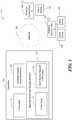
- FIG. 6is a block diagram illustrating one example of a computing system 612.
- the computing system 612may assign client devices to wireless access points for providing network access to the client devices.
- the client devicesmay be assigned to the wireless access points based on the communication protocols of the client devices. For example, client devices communicating with the same communication protocol may be assigned to the same wireless access point. As an example, the client devices may be assigned to the wireless access points in a manner to prevent a wireless anomaly problem caused by client devices using different communication protocols communicating with the same wireless access point.
- the computing system 612may include an apparatus 600, a network 605, a wireless access point A 606, a wireless access point B 607, and client devices 608, 609, and 610.
- the wireless access point A 606 and the wireless access point B 607may be any suitable wireless access points.
- the wireless access points A 606 and B 607may be used to provide network access to client devices 608, 609, and 610, such as by transmitting information wirelessly via radio frequencies to client devices.
- the wireless access points A 606 and B 607may be combined with other network hardware, such as a router.
- the client devices 608, 609, and 610may be desktop, laptop, or mobile computing, or other types of client devices.
- the client devices 608, 609, and 610may be client devices that wirelessly connect to the network 605.
- the client devices 608, 609, and 610may receive access to the network 605 via a wireless access point, such as wireless access point A 606 or wireless access point B 607.
- the wireless access points A 606 and B 607may wirelessly transmit data to the client devices associated with the wireless access points.
- wireless access point B 607may wirelessly transmit data to client devices 608 and 609
- wireless access point A 606may wirelessly transmit data to client device 610.
- the network 605may be, for example, the Internet or a Local Area Network (LAN).
- the network 605may be used to communicate information to the wireless access points A 606 and B 607 about which client devices they should associate with.
- the network 606may be a wired network for transmitting information to the wireless access points A 606 and B 607, and the wireless access points A 606 and 607 may wirelessly transmit the information to client devices 608, 609, and 610.
- the apparatus 600may be any suitable apparatus for controlling network parameters.
- the apparatus 600may be a network controller, such as a wireless Local Area Network (LAN) controller, for controlling wireless access point settings.
- the apparatus 600may determine which wireless access point to associate with a client device.
- the apparatus 600may include a transmitter 601, a wireless access point determiner 602, and a machine-readable storage medium 603.
- the wireless access point determiner 602may be, for example, a processor, such as a central processing unit (CPU), a semiconductor-based microprocessor, or any other device suitable for retrieval and execution of instructions.
- the wireless access point determiner 602includes logic instead of or in addition to a processor.
- the wireless access point determiner 602may include one or more integrated circuits (ICs) or other electronic circuits that comprise a plurality of electronic components for performing the functionality described below.
- the wireless access point determiner 602includes multiple processors. For example, one processor may perform some functionality and another processor may perform other functionality.
- the machine-readable storage medium 603may be any suitable machine readable medium, such as an electronic, magnetic, optical, or other physical storage device that stores executable instructions or other data (e.g., a hard disk drive, random access memory, flash memory, etc.).
- the machine-readable storage medium 603may be, for example, a computer readable non-transitory medium.
- the machine-readable storage medium 603may include client device communication protocol information 604.
- the client device communication protocol information 604may include information about communication protocol used by a client device.
- the machine-readable storage medium 603may include instructions 611 executable by the wireless access point determiner 602. In some implementations, the instructions 611 may be in a separate machine-readable storage medium.
- the instructions 611may include instructions executable by the wireless access point determiner 602 to assign a client device to a wireless access point based on the client device communication protocol information 604. For example, client devices communicating using a first communication protocol may be assigned to a first wireless access point, and client devices communicating using a second communication protocol may be assigned to a second wireless access point.
- the transmitter 601may be, for example, a hardware component of the apparatus 600 for transmitting information via the network 605 to the wireless access points A 606 and B 607.
- the transmitter 601may transmit client device assignment information determined by the wireless access point determiner 602 to the wireless access points A 606 and B 607.
- the transmitter 601may transmit information to the wireless access point A 606 indicating that client device 608 and client device 609 are assigned to it.
- the client devices assigned to the wireless access pointmay communicate wireless via the assigned wireless access point to receive network access.
- Figure 7is a flow chart 700 illustrating one example of a method to assign a client device to a wireless access point based on a communication protocol used by the client device.
- a wireless access pointmay be used for client devices using a particular communication protocol or a group of communication protocols.
- Each wireless access pointmay be configured to support the particular communication protocols.
- Limiting a wireless access point to a particular set of communication protocolsmay limit a small number of client devices using a different communication protocol from slowing down network access with the wireless access point.
- the methodmay result in a client device being assigned to a wireless access point that is not the closest wireless access point to the client device.
- the methodmay be implemented, for example, by the apparatus 700.
- a wireless access point determinerdetermines a wireless access point to assign to a client device based on a communication protocol of the client device.
- the wireless access point determinermay receive information about the communication protocol used by the client device.
- the assignment determinermonitors network traffic from the client device to determine a communication protocol associated with the client device.
- the wireless access pointmay be updated, for example, in response to a detection of an updated communication protocol associated with a client device.
- the wireless access pointmay be associated with the client device for the client device to access the network by communicating wirelessly with the wireless access point.
- a client devicemay communicate using an 802.11a protocol, and it may be assigned to a wireless access point for communicating with client devices communicating using the 802.11a protocol.
- client devices communicating with an older wireless protocolmay be assigned to a different wireless access point than a client device communication with a newer wireless protocol.
- a first wireless access pointmay be designated as a wireless access point for client devices communicating using 802.11n
- a second wireless access pointmay be designated for client devices communicating using 802.11a, 802.11b, or 802.11g.
- the wireless access point determinerdetermines how to allocate the client devices to wireless access points based on the communication protocols of the client devices attempting to connect to the network, and the wireless access points are not first assigned to a particular communication protocol or set of communication protocols.
- the wireless access pointis determined based on both the communication protocol and historical network traffic data associated with the client device. For example, the wireless access point may be selected in order to decrease the likelihood of co-channel interference and to group client devices based on their communication protocols. The wireless access point may be determined further based on a priority of the client device, such as a priority determined based on the type of network traffic historically associated with the client device.
- a transmittersuch as the transmitter 601 from Figure 6 , transmits information about the client device to the wireless access point.
- the transmittermay transmit information about the client device via a wired network. If the client device attempts to connect to the network, the wireless access point assigned to the client device allows the client device to connect to it to receive access to the network.
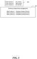
- Figure 8is a diagram illustrating one example of assigning client devices to wireless access points based on communication protocol characteristics of the client devices.
- Block 800shows client devices and their associated communication protocols. For example, client device 1 communicates using 802.11n and client devices 2 and 3 communicate using 802.11a.
- Block 801shows wireless access point assignments. The client devices 1, 2, and 3 assigned to wireless access points. For example, client devices communicating using 802.11a are assigned to wireless access point A, and the client device communicating using 802.11n are assigned to wireless access point B.
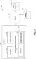
- FIG. 9is a diagram illustrating one example of a computing system 909.
- the computing system 909may be a computing system in which a radio channel is assigned to a wireless access point based on wireless access point network traffic data. For example, historical data of network traffic associated with wireless access points may be analyzed to determine how to assign channels to wireless access points in a manner designed to reduce the likelihood of co-channel interference.
- the datamay be time based such that a wireless access point is assigned a first channel during a first time period and a second channel during a second time period, such as having different channels for morning than for afternoon.
- the wireless access point A 906 and the wireless access point B 907may be any suitable wireless access points.
- the wireless access points A 906 and B 907may be used to provide network access to client devices (not shown), such as by transmitting information wirelessly via radio frequencies to client devices.
- the wireless access points A 906 and B 907may be combined with other network hardware, such as a router.
- the network 905may be, for example, the Internet or a Local Area Network (LAN).
- the network 905may be used to communicate information to the wireless access points A 906 and B 907 about which radio channels they should use to communicate.
- the network 905may be a wired network for transmitting information to the wireless access points A 906 and B 907, and the wireless access points A 906 and 907 may wirelessly transmit the information to client devices.
- the apparatus 900may be any suitable apparatus for controlling network parameters.
- the apparatus 900may be a network controller, such as a wireless Local Area Network (LAN) controller, for controlling wireless access point settings.
- the apparatus 900may determine a radio channel for a wireless access point to use to wirelessly communicate with client devices.
- the apparatus 900may include a transmitter 901, a channel determiner 902, and a machine-readable storage medium 903.
- the channel determiner 902may be, for example, a processor, such as a central processing unit (CPU), a semiconductor-based microprocessor, or any other device suitable for retrieval and execution of instructions.
- the channel determiner 902includes logic instead of or in addition to a processor.
- the channel determiner 902may include one or more integrated circuits (ICs) or other electronic circuits that comprise a plurality of electronic components for performing the functionality described below.
- the channel determiner 902includes multiple processors. For example, one processor may perform some functionality and another processor may perform other functionality.
- the machine-readable storage medium 903may be any suitable machine readable medium, such as an electronic, magnetic, optical, or other physical storage device that stores executable instructions or other data (e.g., a hard disk drive, random access memory, flash memory, etc.).
- the machine-readable storage medium 903may be, for example, a computer readable non-transitory medium.
- the machine-readable storage medium 903may include wireless access point network traffic data 904.
- the wireless access point network traffic data 904may include historical network traffic data associated with a wireless access point.
- the historical network traffic datamay indicate time based patterns of network traffic.
- the machine-readable storage medium 903, or a separate storagemay include instructions 908 executable by the channel determiner 902 to assign radio channels to wireless access points based on the wireless access point network traffic data 904.
- the channel determiner 902may analyze traffic patterns to determine the degree of interference if a wireless access point shared a radio channel with a nearby wireless access point.
- the transmitter 901may be, for example, a hardware component of the apparatus 900 for transmitting radio channel information via the network 905 to the wireless access points A 906 and B 907.
- the transmitter 901may transmit information to the wireless access point A 906 indicating that the wireless access point A 906 should transmit using a particular radio channel.
- the informationmay be transmitted to the wireless access points with the associated time information, or the transmitter 901 may transmit the channel information to the wireless access points at the point when the wireless access point should switch radio channels.
- FIG 10is a flow chart 1000 illustrating one example of a method to assign a radio channel to a wireless access point based on network traffic patterns.
- Traffic patternsmay be determined for a wireless access point. For example, historical network traffic data may be analyzed to determine typical amounts or types of network traffic during different time periods.
- the radio channelmay be assigned based on the concept that future network traffic is likely to resemble past traffic patterns. The pattern may be used to determine a radio channel to assign to the wireless access point for communicating wirelessly with client devices.
- the wireless access pointmay be assigned different channels at different times, such as a first channel during a time identified as a peak traffic time period in the past and a second channel during a time period associated with more moderate network traffic.
- the radio channelmay be assigned in a manner designed to reduce co-channel interference.
- a wireless access point predicted to have greater traffic based on the historical patternmay be assigned to a radio not assigned to another wireless access point or to a radio channel assigned to a wireless access point predicted to have a lower amount of traffic during the particular time period.
- the methodmay be implemented, for example, by the apparatus 900 of Figure 9 .
- a channel determinerdetermines a wireless access point network time based traffic pattern based on stored data related to previous network traffic associated with the wireless access point.
- the channel determinermay store the network traffic data or access data collected by another component or entity.
- the network traffic datamay indicate the amount and/or type of network traffic received by the wireless access point.
- the channel determinermay determine a pattern of network traffic based on time periods. The periods may be predetermined, and the channel determiner determines a typical past amount of traffic at each of the predetermined time periods.
- the channel determineranalyzes the network traffic data and groups the network traffic data into time periods based on the network traffic data.
- the patternsmay be based on, for example, a time of day or day of week. In some cases, the patterns may be related to an area of a building, such as related to a group of wireless access points located in an area of a building.
- the channel determinerselects a radio channel for the wireless access point based on the determined pattern.
- the radio channelmay be selected in a manner designed to decrease the likelihood of co-channel interference. For example, if two nearby wireless access points use the same radio channel, the amount of throughput for each wireless access point may be reduced.
- the radio channelmay be selected based on the projected throughput of the radio channel. For example, the projected throughput for each wireless access point may be 50% where two nearby wireless points use the same radio channel.
- a wireless access point with a greater amount of traffic predicted for a particular time periodmay be assigned to another radio channel not assigned to other wireless access points to increase the throughput for the wireless access point with greater traffic.
- the radio channelis selected based on the priority of the wireless access point. For example, a wireless access point in an auditorium may receive a higher priority than a wireless access point covering a guest office.
- the radio channelmay be selected in a manner designed to reduce co-channel interference for a wireless access point with a greater priority.
- the traffic patternis used both for the radio channel assignment and to update which client devices connect to the wireless access point. For example, a wireless access point with a pattern of high traffic during a particular period may not be assigned to an additional client device even if the wireless access point is the closest wireless access point to the client device. Information about the assignment may be transmitted to the wireless access point to be used when the client device attempts to connect to the network.
- a transmittersuch as the transmitter 901 from Figure 9 , transmits information related to the selected channel to the wireless access point.
- the transmittermay transmit information about the channel to the wireless access point via a wired network, and the wireless access point may then begin communicating with client devices via the selected radio channel.
- the wireless access pointmay store information about which radio channel to use during particular time periods.
- the transmittertransmits information about the radio channel at the beginning of each time period where the wireless access point is determined to switch radio channels.
- Figure 11is a diagram illustrating assigning radio channels to wireless access points based on historical network traffic data.
- block 1100shows channel assignments for wireless access point A
- block 1101shows channel assignment information for wireless access point B
- block 1102shows channel assignment information for wireless access point C.
- the channelsare assigned such that times of high traffic for a wireless access point do not have the wireless access point sharing a radio channel with another wireless access point with high traffic in order to reduce the likelihood of co-channel interference.
- wireless access point Ahas high traffic and wireless access points B and C have low traffic.
- Wireless access point Ais assigned to radio channel 1
- wireless access points B and Care assigned to radio channel 11.
Landscapes
- Engineering & Computer Science (AREA)
- Computer Networks & Wireless Communication (AREA)
- Signal Processing (AREA)
- Computer Security & Cryptography (AREA)
- Mobile Radio Communication Systems (AREA)
Description
- Wireless networks allow client devices to wirelessly connect to wireless access points to receive network access. A central network controller may control the wireless access points, for example, by selecting radio channels for transmission by the wireless access points. The central network controller may control the network configuration, such as by determining which wireless access point a client device connects to.
US 2007/0249291 A1 discloses a wireless communication method in which the current state of an access terminal is monitored.US 2007/0217377 A1 discloses a wireless communication method for access point selection.US 5,697,059 discloses a system for dynamically allocating channels among base stations in a wireless communication system.- The drawings describe examples. The following detailed description references the drawings, wherein:
Figure 1 is a block diagram illustrating one example of a computing system.Figure 2 is a flow chart illustrating one example of a method to assign a client device to a wireless access point based on stored network traffic data.Figure 3 is a diagram illustrating one example of assigning client devices to wireless access points based on network traffic data.Figure 4 is a diagram illustrating one example of assigning client devices to wireless access points based on time based network traffic data.Figure 5 is a diagram illustrating one example of assigning client devices to wireless access points based on network traffic priorities data.Figure 6 is a block diagram illustrating one example of a computing system.Figure 7 is a flow chart illustrating one example of a method to assign a client device to a wireless access point based on a communication protocol used by the client device.Figure 8 is a diagram illustrating one example of assigning client devices to wireless access points based on the communication protocols used by the client devices.Figure 9 is a diagram illustrating one example of a computing system.Figure 10 is a flow chart illustrating one example of a method to assign a radio channel to a wireless access point based on network traffic patterns.Figure 11 is a diagram illustrating one example of assigning radio channels to wireless access points based on historical network traffic data.- A wireless network may involve client devices communicating wirelessly with a wireless access point to access a network. A network controller may analyze network patterns, such as client device characteristics or traffic patterns, to determine how to configure wireless access points. For example, a network controller may determine which client devices to assign to a wireless access point and which radio channel to assign to a wireless access point.
- As an example, a network controller may assign client devices to wireless access points based on the traffic patterns of the client devices. Client devices with greater traffic or a higher priority type of traffic may be assigned to a wireless access point likely to provide greater throughput to the client device than a client device previously associated with a lower amount of network traffic.
- As another example, client devices may be assigned to wireless access points based on the communication protocol use by the client devices. For example, client devices using an older wireless technology may connect to a different wireless access point than client devices communicating using a newer communication protocol. For example, client devices communicating using 802.11n may access a network through a first wireless access point and client devices communicating using 802.11a may access the network through a second wireless access point.
- As another example, a network controller may analyze network traffic patterns associated with a wireless access point and assign a radio channel to the wireless access point based on the traffic patterns. For example, the radio channel may be selected to reduce co-channel interference and increase throughput for the wireless access point that has a greater level of traffic. The radio channel may be assigned for a particular time period. For example, a first radio channel may be assigned to the wireless access point for Tuesdays, and a second radio channel may be assigned to the wireless access point for Saturdays.
Figure 1 is a block diagram illustrating one example of acomputing system 112. Thecomputing system 112 may be a network in which a central network controller determines which wireless access point to associate with a particular client device. For example, network traffic originating from the client devices may be analyzed to determine how to allocate the client devices among the wireless access points. Thecomputing system 112 may include anapparatus 100, anetwork 105, a wirelessaccess point A 106, a wirelessaccess point B 107, aclient device 108, aclient device 109, and aclient device 110.- The wireless
access point A 106 and the wirelessaccess point B 107 may be any suitable wireless access points. The wireless access points A 106 and B 107 may be used to provide wireless network access to client devices, such as by transmitting information wirelessly via radio frequencies toclient devices - The
client devices client device network 105. For example, theclient devices network 105 via a wireless access point, such as wirelessaccess point A 107 or wirelessaccess point B 108. The wirelessaccess points A 107 andB 108 may wirelessly transmit data to the client devices associated with the wireless access points. For example, wirelessaccess point B 107 may wirelessly transmit data to theclient devices client device 110. - The
network 105 may be, for example, the Internet or a Local Area Network (LAN). Thenetwork 105 may be used to communicate information to the wirelessaccess points A 106 andB 107 about which client devices they should associate with. Thenetwork 105 may be a wired network for transmitting information to the wireless access points A 106 andB 107, and the wirelessaccess points A - The
apparatus 100 may be any suitable apparatus for controlling network parameters. For example, theapparatus 100 may be a network controller, such as a wireless Local Area Network (LAN) controller, for centrally managing radio frequency power, channel, authentication, and security of wireless access points. Theapparatus 100 may determine which wireless access point to associate with a client device. Theapparatus 100 may include atransmitter 101, a wireless access point determiner 102, and a machine-readable storage medium 103. - The wireless
access point determiner 102 may be, for example, a processor, such as a central processing unit (CPU), a semiconductor-based microprocessor, or any other device suitable for retrieval and execution of instructions. In one embodiment, the wireless access point determiner 102 includes logic instead of or in addition to a processor. As an alternative or in addition to fetching, decoding, and executing instructions, the wireless access point determiner 102 may include one or more integrated circuits (ICs) or other electronic circuits that comprise a plurality of electronic components for performing the functionality described below. In one implementation, the wireless access point determiner 102 includes multiple processors. For example, one processor may perform some functionality and another processor may perform other functionality. - The machine-
readable storage medium 103 may be any suitable machine readable medium, such as an electronic, magnetic, optical, or other physical storage device that stores executable instructions or other data (e.g., a hard disk drive, random access memory, flash memory, etc.). The machine-readable storage medium 103 may be, for example, a computer readable non-transitory medium. - The machine-
readable storage medium 103 may include client devicenetwork traffic data 104. The client devicenetwork traffic data 104 may include data related to network traffic originating from each client device. The client devicenetwork traffic data 104 may include information about time based traffic patterns related to, for example, a time of day or a day of the week. - The machine-
readable storage medium 103 may includeinstructions 111 executable by the wireless access point determiner 102. Theinstructions 111 may include instructions executable by the wireless access point determiner 102 to analyze the client devicenetwork traffic data 104 to determine which wireless access point to assign to a client device for network connectivity. The wirelessaccess point determiner 102 may use the client devicenetwork traffic data 104 to determine a wireless access point assignment for a client device likely to result in better throughput, such as by allocating client devices in a manner likely to more evenly distribute network traffic among wireless access points. For example, based on an analysis of the client devicenetwork traffic data 104, the wirelessaccess point determiner 102 may assignclient device 108 to wirelessaccess point B 107. - The
transmitter 101 may be, for example, a hardware component of theapparatus 100 for transmitting information via thenetwork 105 to the wireless access points A 106 andB 107. Thetransmitter 101 may transmit client device assignment information determined by theassignment determiner 102 to the wireless access points A 106 andB 107. For example, thetransmitter 101 may transmit information to the wirelessaccess point A 106 indicating thatclient device 108 andclient device 109 is assigned to it, and wirelessaccess point A 106 may connect to theclient devices network 105. Figure 2 is aflow chart 200 illustrating one example of a method to assign a client device to a wireless access point based on stored network traffic data. For example, network traffic history data may be analyzed, and client devices may be assigned to a wireless access point based on the analysis. The past traffic pattern data may be indicative of future traffic patterns. The traffic patterns may be time based, for example, showing an average amount of past traffic at different time periods. In some cases, the client devices may be assigned in a manner designed to increase the throughput of network traffic of client devices or a group of client devices. If a first wireless access point receives more network traffic than a second wireless access point, the first wireless access point may provide lower throughput to its client devices because more client devices may be communicating on the same radio channel used by the first wireless access point. The client devices may be assigned to different wireless access points at different time periods based on the time based traffic patterns. In some cases, a client device may not be assigned to the closest wireless access point to the client device. The method may be implemented, for example, by theapparatus 100 fromFigure 1 .- Beginning at 201, a wireless access point determiner, such as the wireless
access point determiner 102 fromFigure 1 , determines a wireless access point to assign a client device to based on stored network traffic data associated with the client device. For example, the wireless access point determiner may examine historical network traffic data or patterns determined based on historical network traffic data. The wireless access point determiner may assign a client device to a wireless access point, for example, based on the amount of traffic associated with the client device or the type of network traffic associated with the client device. The assignment may be done to increase throughput for a particular type of network traffic, a particular type of client device, such as a client device associated with a particular type of user, or to even out the throughput across client devices. In some implementations, the assignment may be updated as new traffic pattern data is received or at a particular interval. - The wireless access point determiner may collect the network traffic data or receive the network traffic data. In some cases, the wireless access point determiner receives summary information about the network traffic data, such as information about patterns of high network traffic.
- The assignment may be updated or may be different according to time. For example, a client device may be assigned to a first wireless access point in the morning and to a second wireless access point in the afternoon based on a pattern indicating that the client device in the past had more network traffic in the afternoon.
- As another example, a particular conference room may create a greater amount of network traffic from 8 until 9 each morning due to a daily meeting. The wireless access point determiner may receive information about the pattern of traffic for the client devices indicating increased traffic during the time period of the meeting. The dient devices in that conference room may be assigned to different wireless access point during the meeting time than during the rest of the day.
- In one implementation, the client devices are assigned to wireless access points in a manner designed to provide optimal network access for the client devices as a whole, such as where one client device does not have a much greater throughput than another client device. In one implementation, client devices are prioritized relative to one another. For example, clients may be prioritized based on the type of network traffic or the type of user of the client device. The client devices may then be assigned to wireless access points in a manner that increases throughput for client devices of greater priority. For example, client devices showing historical network traffic data associated with video editing may be given a higher priority than client devices showing historical network traffic data associated with website surfing.
- Continuing to 202, a transmitter, such as the
transmitter 101, transmits to the wireless access point information about the client device assigned to the wireless access point. The transmitter may transmit information to the wireless access point via a wired network. When the client device attempts to connect to the network, the wireless access point assigned to the client device begins to wirelessly communicate with the client device to provide network access to the client device. Figure 3 is a diagram illustrating one example of assigning client devices to wireless access points based on network traffic data.Block 300 shows historical network traffic data. For example, data collected about past network traffic indicates thatclient device 1 has high traffic,client device 2 has low traffic, andclient device 3 has low traffic.Block 301 shows the wireless access point assignments. The two client devices with low traffic,client devices client device 1, is associated with wireless access point B. The wireless access points A and B may communicate using different radio channels.Client devices A. Client device 1 may communicate using another radio channel associated with wireless access point B. As a result,client device 1 may not experience co-channel interference withclient devices client devices traffic client device 1 shared a radio channel withclient devices client device 1.Figure 4 is a diagram illustrating one example of assigning client devices to wireless access points based on time based network traffic data. Historical network traffic data may reveal that a client device has a pattern of network traffic based on time, such as time of day, day of week, month of year, or other time based pattern. For example, a client device may have a low amount of network traffic on the weekends, but a high amount of network traffic during the week.Block 400 shows historical time based network traffic data where the network traffic patterns are shown for morning and afternoon. For example,client device 1 has high traffic in the morning and low traffic in the afternoon.Block 401 shows morning wireless access point assignments. In the morning,client devices client device 1 is assigned to wireless access pointB. Client device 1 communicates on a radio channel associated with wireless access point B so that it does not create interference on the radio channel of wireless access point A due to the high volume morning network traffic ofclient device 1.Block 402 shows client device afternoon wireless access point assignments. The client devices may be assigned to different wireless access points in the afternoon than in the morning due to different past network traffic patterns in the morning than in the afternoon.Client devices client device 3 is assigned to wireless access point B.Figure 5 is a diagram illustrating one example of assigning client devices to wireless access points based on network traffic priorities data.Block 500 shows historical traffic patterns indicating the priority of network traffic.Client devices client 2 has high priority traffic data. Client devices with low priority,client devices client device 2. In some cases, client devices with different priority levels may be assigned to the same wireless access point where the configuration is designed to increase the throughput for the higher priority client device.Figure 6 is a block diagram illustrating one example of acomputing system 612. Thecomputing system 612 may assign client devices to wireless access points for providing network access to the client devices. The client devices may be assigned to the wireless access points based on the communication protocols of the client devices. For example, client devices communicating with the same communication protocol may be assigned to the same wireless access point. As an example, the client devices may be assigned to the wireless access points in a manner to prevent a wireless anomaly problem caused by client devices using different communication protocols communicating with the same wireless access point. Thecomputing system 612 may include anapparatus 600, anetwork 605, a wirelessaccess point A 606, a wirelessaccess point B 607, andclient devices - The wireless
access point A 606 and the wirelessaccess point B 607 may be any suitable wireless access points. The wireless access points A 606 andB 607 may be used to provide network access toclient devices B 607 may be combined with other network hardware, such as a router. - The
client devices client devices network 605. For example, theclient devices network 605 via a wireless access point, such as wirelessaccess point A 606 or wirelessaccess point B 607. The wireless access points A 606 andB 607 may wirelessly transmit data to the client devices associated with the wireless access points. For example, wirelessaccess point B 607 may wirelessly transmit data toclient devices access point A 606 may wirelessly transmit data toclient device 610. - The
network 605 may be, for example, the Internet or a Local Area Network (LAN). Thenetwork 605 may be used to communicate information to the wireless access points A 606 andB 607 about which client devices they should associate with. Thenetwork 606 may be a wired network for transmitting information to the wireless access points A 606 andB 607, and the wireless access points A 606 and 607 may wirelessly transmit the information toclient devices - The
apparatus 600 may be any suitable apparatus for controlling network parameters. For example, theapparatus 600 may be a network controller, such as a wireless Local Area Network (LAN) controller, for controlling wireless access point settings. Theapparatus 600 may determine which wireless access point to associate with a client device. Theapparatus 600 may include atransmitter 601, a wirelessaccess point determiner 602, and a machine-readable storage medium 603. - The wireless
access point determiner 602 may be, for example, a processor, such as a central processing unit (CPU), a semiconductor-based microprocessor, or any other device suitable for retrieval and execution of instructions. In one embodiment, the wirelessaccess point determiner 602 includes logic instead of or in addition to a processor. As an alternative or in addition to fetching, decoding, and executing instructions, the wirelessaccess point determiner 602 may include one or more integrated circuits (ICs) or other electronic circuits that comprise a plurality of electronic components for performing the functionality described below. In one implementation, the wirelessaccess point determiner 602 includes multiple processors. For example, one processor may perform some functionality and another processor may perform other functionality. - The machine-
readable storage medium 603 may be any suitable machine readable medium, such as an electronic, magnetic, optical, or other physical storage device that stores executable instructions or other data (e.g., a hard disk drive, random access memory, flash memory, etc.). The machine-readable storage medium 603 may be, for example, a computer readable non-transitory medium. - The machine-
readable storage medium 603 may include client devicecommunication protocol information 604. The client devicecommunication protocol information 604 may include information about communication protocol used by a client device. The machine-readable storage medium 603 may includeinstructions 611 executable by the wirelessaccess point determiner 602. In some implementations, theinstructions 611 may be in a separate machine-readable storage medium. Theinstructions 611 may include instructions executable by the wirelessaccess point determiner 602 to assign a client device to a wireless access point based on the client devicecommunication protocol information 604. For example, client devices communicating using a first communication protocol may be assigned to a first wireless access point, and client devices communicating using a second communication protocol may be assigned to a second wireless access point. - The
transmitter 601 may be, for example, a hardware component of theapparatus 600 for transmitting information via thenetwork 605 to the wireless access points A 606 andB 607. Thetransmitter 601 may transmit client device assignment information determined by the wirelessaccess point determiner 602 to the wireless access points A 606 andB 607. For example, thetransmitter 601 may transmit information to the wirelessaccess point A 606 indicating thatclient device 608 andclient device 609 are assigned to it. The client devices assigned to the wireless access point may communicate wireless via the assigned wireless access point to receive network access. Figure 7 is aflow chart 700 illustrating one example of a method to assign a client device to a wireless access point based on a communication protocol used by the client device. For example, a wireless access point may be used for client devices using a particular communication protocol or a group of communication protocols. Each wireless access point may be configured to support the particular communication protocols. Limiting a wireless access point to a particular set of communication protocols may limit a small number of client devices using a different communication protocol from slowing down network access with the wireless access point. In some cases, the method may result in a client device being assigned to a wireless access point that is not the closest wireless access point to the client device. The method may be implemented, for example, by theapparatus 700.- Beginning at 701, a wireless access point determiner, such as the wireless
access point determiner 602 fromFigure 6 , determines a wireless access point to assign to a client device based on a communication protocol of the client device. The wireless access point determiner may receive information about the communication protocol used by the client device. In some implementations, the assignment determiner monitors network traffic from the client device to determine a communication protocol associated with the client device. The wireless access point may be updated, for example, in response to a detection of an updated communication protocol associated with a client device. The wireless access point may be associated with the client device for the client device to access the network by communicating wirelessly with the wireless access point. As an example, a client device may communicate using an 802.11a protocol, and it may be assigned to a wireless access point for communicating with client devices communicating using the 802.11a protocol. - In some implementations, client devices communicating with an older wireless protocol may be assigned to a different wireless access point than a client device communication with a newer wireless protocol. For example, a first wireless access point may be designated as a wireless access point for client devices communicating using 802.11n, and a second wireless access point may be designated for client devices communicating using 802.11a, 802.11b, or 802.11g. In some implementations, the wireless access point determiner determines how to allocate the client devices to wireless access points based on the communication protocols of the client devices attempting to connect to the network, and the wireless access points are not first assigned to a particular communication protocol or set of communication protocols.
- In one implementation, the wireless access point is determined based on both the communication protocol and historical network traffic data associated with the client device. For example, the wireless access point may be selected in order to decrease the likelihood of co-channel interference and to group client devices based on their communication protocols. The wireless access point may be determined further based on a priority of the client device, such as a priority determined based on the type of network traffic historically associated with the client device.
- Continuing to 702, a transmitter, such as the
transmitter 601 fromFigure 6 , transmits information about the client device to the wireless access point. For example, the transmitter may transmit information about the client device via a wired network. If the client device attempts to connect to the network, the wireless access point assigned to the client device allows the client device to connect to it to receive access to the network. Figure 8 is a diagram illustrating one example of assigning client devices to wireless access points based on communication protocol characteristics of the client devices.Block 800 shows client devices and their associated communication protocols. For example,client device 1 communicates using 802.11n andclient devices Block 801 shows wireless access point assignments. Theclient devices Figure 9 is a diagram illustrating one example of acomputing system 909. Thecomputing system 909 may be a computing system in which a radio channel is assigned to a wireless access point based on wireless access point network traffic data. For example, historical data of network traffic associated with wireless access points may be analyzed to determine how to assign channels to wireless access points in a manner designed to reduce the likelihood of co-channel interference. The data may be time based such that a wireless access point is assigned a first channel during a first time period and a second channel during a second time period, such as having different channels for morning than for afternoon.- The wireless
access point A 906 and the wirelessaccess point B 907 may be any suitable wireless access points. The wireless access points A 906 andB 907 may be used to provide network access to client devices (not shown), such as by transmitting information wirelessly via radio frequencies to client devices. In some implementations, the wireless access points A 906 andB 907 may be combined with other network hardware, such as a router. - The
network 905 may be, for example, the Internet or a Local Area Network (LAN). Thenetwork 905 may be used to communicate information to the wireless access points A 906 andB 907 about which radio channels they should use to communicate. Thenetwork 905 may be a wired network for transmitting information to the wireless access points A 906 andB 907, and the wireless access points A 906 and 907 may wirelessly transmit the information to client devices. - The
apparatus 900 may be any suitable apparatus for controlling network parameters. For example, theapparatus 900 may be a network controller, such as a wireless Local Area Network (LAN) controller, for controlling wireless access point settings. Theapparatus 900 may determine a radio channel for a wireless access point to use to wirelessly communicate with client devices. Theapparatus 900 may include atransmitter 901, achannel determiner 902, and a machine-readable storage medium 903. - The
channel determiner 902 may be, for example, a processor, such as a central processing unit (CPU), a semiconductor-based microprocessor, or any other device suitable for retrieval and execution of instructions. In one embodiment, thechannel determiner 902 includes logic instead of or in addition to a processor. As an alternative or in addition to fetching, decoding, and executing instructions, thechannel determiner 902 may include one or more integrated circuits (ICs) or other electronic circuits that comprise a plurality of electronic components for performing the functionality described below. In one implementation, thechannel determiner 902 includes multiple processors. For example, one processor may perform some functionality and another processor may perform other functionality. - The machine-
readable storage medium 903 may be any suitable machine readable medium, such as an electronic, magnetic, optical, or other physical storage device that stores executable instructions or other data (e.g., a hard disk drive, random access memory, flash memory, etc.). The machine-readable storage medium 903 may be, for example, a computer readable non-transitory medium. - The machine-
readable storage medium 903 may include wireless access pointnetwork traffic data 904. The wireless access pointnetwork traffic data 904 may include historical network traffic data associated with a wireless access point. The historical network traffic data may indicate time based patterns of network traffic. The machine-readable storage medium 903, or a separate storage, may includeinstructions 908 executable by thechannel determiner 902 to assign radio channels to wireless access points based on the wireless access pointnetwork traffic data 904. For example, thechannel determiner 902 may analyze traffic patterns to determine the degree of interference if a wireless access point shared a radio channel with a nearby wireless access point. - The
transmitter 901 may be, for example, a hardware component of theapparatus 900 for transmitting radio channel information via thenetwork 905 to the wireless access points A 906 andB 907. For example, thetransmitter 901 may transmit information to the wirelessaccess point A 906 indicating that the wirelessaccess point A 906 should transmit using a particular radio channel. The information may be transmitted to the wireless access points with the associated time information, or thetransmitter 901 may transmit the channel information to the wireless access points at the point when the wireless access point should switch radio channels. Figure 10 is aflow chart 1000 illustrating one example of a method to assign a radio channel to a wireless access point based on network traffic patterns. Traffic patterns may be determined for a wireless access point. For example, historical network traffic data may be analyzed to determine typical amounts or types of network traffic during different time periods. The radio channel may be assigned based on the concept that future network traffic is likely to resemble past traffic patterns. The pattern may be used to determine a radio channel to assign to the wireless access point for communicating wirelessly with client devices. The wireless access point may be assigned different channels at different times, such as a first channel during a time identified as a peak traffic time period in the past and a second channel during a time period associated with more moderate network traffic. The radio channel may be assigned in a manner designed to reduce co-channel interference. For example, a wireless access point predicted to have greater traffic based on the historical pattern may be assigned to a radio not assigned to another wireless access point or to a radio channel assigned to a wireless access point predicted to have a lower amount of traffic during the particular time period. The method may be implemented, for example, by theapparatus 900 ofFigure 9 .- Beginning at 1001, a channel determiner, such as the
channel determiner 902 ofFigure 9 , determines a wireless access point network time based traffic pattern based on stored data related to previous network traffic associated with the wireless access point. The channel determiner may store the network traffic data or access data collected by another component or entity. The network traffic data may indicate the amount and/or type of network traffic received by the wireless access point. The channel determiner may determine a pattern of network traffic based on time periods. The periods may be predetermined, and the channel determiner determines a typical past amount of traffic at each of the predetermined time periods. In one implementation, the channel determiner analyzes the network traffic data and groups the network traffic data into time periods based on the network traffic data. The patterns may be based on, for example, a time of day or day of week. In some cases, the patterns may be related to an area of a building, such as related to a group of wireless access points located in an area of a building. - Continuing to 1002, the channel determiner selects a radio channel for the wireless access point based on the determined pattern. The radio channel may be selected in a manner designed to decrease the likelihood of co-channel interference. For example, if two nearby wireless access points use the same radio channel, the amount of throughput for each wireless access point may be reduced. The radio channel may be selected based on the projected throughput of the radio channel. For example, the projected throughput for each wireless access point may be 50% where two nearby wireless points use the same radio channel. A wireless access point with a greater amount of traffic predicted for a particular time period may be assigned to another radio channel not assigned to other wireless access points to increase the throughput for the wireless access point with greater traffic.
- In one implementation, the radio channel is selected based on the priority of the wireless access point. For example, a wireless access point in an auditorium may receive a higher priority than a wireless access point covering a guest office. The radio channel may be selected in a manner designed to reduce co-channel interference for a wireless access point with a greater priority.
- In one implementation, the traffic pattern is used both for the radio channel assignment and to update which client devices connect to the wireless access point. For example, a wireless access point with a pattern of high traffic during a particular period may not be assigned to an additional client device even if the wireless access point is the closest wireless access point to the client device. Information about the assignment may be transmitted to the wireless access point to be used when the client device attempts to connect to the network.
- Proceeding to 1003, a transmitter, such as the
transmitter 901 fromFigure 9 , transmits information related to the selected channel to the wireless access point. For example, the transmitter may transmit information about the channel to the wireless access point via a wired network, and the wireless access point may then begin communicating with client devices via the selected radio channel. The wireless access point may store information about which radio channel to use during particular time periods. In one implementation, the transmitter transmits information about the radio channel at the beginning of each time period where the wireless access point is determined to switch radio channels. Figure 11 is a diagram illustrating assigning radio channels to wireless access points based on historical network traffic data. For example, block 1100 shows channel assignments for wireless access point A,block 1101 shows channel assignment information for wireless access point B, and block 1102 shows channel assignment information for wireless access point C. The channels are assigned such that times of high traffic for a wireless access point do not have the wireless access point sharing a radio channel with another wireless access point with high traffic in order to reduce the likelihood of co-channel interference. For example, in the morning, wireless access point A has high traffic and wireless access points B and C have low traffic. Wireless access point A is assigned toradio channel 1, and wireless access points B and C are assigned toradio channel 11.
Claims (9)
- A method of assigning a client device to a wireless access point, comprising:analyzing stored network traffic data associated with the client device (108 -110);determining a time based pattern of network traffic associated with the client device using the analyzed stored network traffic data;determining the wireless access point (106, 107) to assign the client device to based on the time based pattern; andtransmitting to the wireless access point, information about the client device assigned to the wireless access point.
- The method of claim 1, wherein determining the wireless access point to assign the client device to is based on an amount of network traffic associated with the client device.
- The method of claim 1 further comprising:assigning a radio channel to the wireless access point based on the stored network traffic data; andtransmitting information about the radio channel to the wireless access point.
- The method of claim 1, wherein determining the wireless access point to assign the client device to is based on a type of network traffic associated with the client device.
- A non-transitory machine readable storage medium (603) including instructions (611) executable by a processor to:analyze stored network traffic data associated with a client device (608-610);determine a time based pattern of network traffic associated with the client device using the analyzed stored network traffic data;determine a wireless access point (606, 607) to assign the client device to based on the time based pattern; andtransmit information about the client device to the wireless access point.
- The non-transitory machine-readable medium of claim 5, wherein the instructions are to determine the wireless access point to assign the client device to further based on a communication protocol of the client device.
- The non-transitory machine-readable storage medium of claim 6, wherein one client device communicating with an older wireless protocol is associated with a different wireless access point than one client device communicating with a newer wireless protocol.
- The non-transitory machine-readable storage medium of claim 5, further comprising instructions to determine the wireless access point based on a priority for network connectivity of the client device.
- The non-transitory machine-readable storage medium of claim 5, further comprising instructions to:collect historical data about a communication protocol of the client device; andupdate the determination of the wireless access point based on changes in the communication protocol of the client device.
Applications Claiming Priority (1)
| Application Number | Priority Date | Filing Date | Title |
|---|---|---|---|
| PCT/US2012/020437WO2013103349A1 (en) | 2012-01-06 | 2012-01-06 | Wireless access point assignment |
Publications (3)
| Publication Number | Publication Date |
|---|---|
| EP2801231A1 EP2801231A1 (en) | 2014-11-12 |
| EP2801231A4 EP2801231A4 (en) | 2015-08-05 |
| EP2801231B1true EP2801231B1 (en) | 2021-03-03 |
Family
ID=48745339
Family Applications (1)
| Application Number | Title | Priority Date | Filing Date |
|---|---|---|---|
| EP12864664.3AActiveEP2801231B1 (en) | 2012-01-06 | 2012-01-06 | Wireless access point assignment |
Country Status (4)
| Country | Link |
|---|---|
| US (1) | US9351197B2 (en) |
| EP (1) | EP2801231B1 (en) |
| CN (1) | CN104025686A (en) |
| WO (1) | WO2013103349A1 (en) |
Families Citing this family (23)
| Publication number | Priority date | Publication date | Assignee | Title |
|---|---|---|---|---|
| CN102938880B (en)* | 2011-08-15 | 2015-12-16 | 宏碁股份有限公司 | Method for forming wireless communication group |
| US9049731B2 (en)* | 2012-12-03 | 2015-06-02 | At&T Mobility Ii Llc | Facilitation of bandwidth-based femto cell management |
| US9591562B2 (en)* | 2013-10-31 | 2017-03-07 | Aruba Networks, Inc. | Provisioning access point bandwidth based on predetermined events |
| US10070378B2 (en)* | 2014-02-07 | 2018-09-04 | Fortinet, Inc. | Steering inherently autonomous wireless devices to access points based on MIMO (multiple input/ multiple output) capabilities of network components |
| CN104902514A (en)* | 2014-03-07 | 2015-09-09 | 中兴通讯股份有限公司 | Load balance method and device |
| DE102014204886A1 (en)* | 2014-03-17 | 2015-10-01 | Rohde & Schwarz Gmbh & Co. Kg | Radio transmission system and radio transmission method with multiple channel access |
| US9918322B2 (en)* | 2014-05-23 | 2018-03-13 | embedUR systems, Inc. | Radio resources management system |
| US10904122B2 (en)* | 2014-10-28 | 2021-01-26 | Salesforce.Com, Inc. | Facilitating workload-aware shuffling and management of message types in message queues in an on-demand services environment |
| US9736719B2 (en)* | 2015-01-30 | 2017-08-15 | Aruba Networks, Inc. | Adaptive resource allocation in congested wireless local area network deployment |
| KR102441168B1 (en)* | 2015-05-08 | 2022-09-07 | 삼성전자주식회사 | Resource allocation apparatus and method for vehicle sevices |
| US9826479B2 (en)* | 2015-10-13 | 2017-11-21 | Aerohive Networks, Inc. | Hybrid low power network device |
| US20170111854A1 (en)* | 2015-10-15 | 2017-04-20 | Qualcomm Incorporated | Quality of service aware access point and device steering |
| US11841830B2 (en)* | 2015-11-01 | 2023-12-12 | International Business Machines Corporation | Dynamic switching of catalog sharing protocols |
| CN107484243B (en) | 2016-06-07 | 2021-02-23 | 华为技术有限公司 | Resource allocation notification method and device |
| US10573144B2 (en)* | 2016-10-10 | 2020-02-25 | Netgear, Inc. | Changing topology in a wireless network |
| EP3539314B1 (en) | 2016-11-11 | 2021-01-06 | Koninklijke Philips N.V. | Device-side testing and reporting for network infrastructure monitoring |
| US11363527B2 (en) | 2019-05-31 | 2022-06-14 | Hewlett Packard Enterprise Development Lp | Adjusting power states of access points |
| US12107875B2 (en)* | 2019-06-14 | 2024-10-01 | Zscaler, Inc. | Network device identification via similarity of operation and auto-labeling |
| CN114556872B (en)* | 2019-10-18 | 2023-10-03 | 深圳市欢太科技有限公司 | Wireless communication method, device, electronic equipment and storage medium |
| US11212188B2 (en)* | 2020-02-07 | 2021-12-28 | Facebook, Inc. | Communication network out-of-capacity predictions |
| US11570707B2 (en)* | 2021-01-11 | 2023-01-31 | Dell Products L.P. | Systems and methods for comparison and scoring of network access points |
| CN116193611A (en)* | 2021-11-24 | 2023-05-30 | 中兴通讯股份有限公司 | Service access point determination method, service access point information transmission method, communication node and storage medium |
| US12418821B2 (en) | 2022-06-07 | 2025-09-16 | HCL America Inc. | Awareness layers for managing access points in centralized wireless networks |
Citations (3)
| Publication number | Priority date | Publication date | Assignee | Title |
|---|---|---|---|---|
| US5697059A (en)* | 1994-05-19 | 1997-12-09 | Airnet Communications Corp. | System for dynamically allocating channels among base stations in a wireless communication system |
| US20070217377A1 (en)* | 2006-03-20 | 2007-09-20 | Nokia Corporation | Method, mobile station, and software product for access point selection |
| US20070249291A1 (en)* | 2006-04-20 | 2007-10-25 | Sanjiv Nanda | Wireless handoffs between multiple networks |
Family Cites Families (17)
| Publication number | Priority date | Publication date | Assignee | Title |
|---|---|---|---|---|
| KR100489683B1 (en)* | 2002-12-02 | 2005-05-17 | 삼성전자주식회사 | Apparatus for controlling the load balance in multi-access points and method thereof |
| KR20070058475A (en) | 2004-08-31 | 2007-06-08 | 에이티 앤드 티 코포레이션 | Method and system for allocating channels in WLAN |
| US8737920B2 (en) | 2004-11-10 | 2014-05-27 | Interdigital Technology Corporation | Method and apparatus for managing wireless communication network radio resources |
| WO2008037109A1 (en)* | 2006-09-22 | 2008-04-03 | 3Dsp(Beijing)Limited Corporation | A transceiver, wireless communication device and wireless communication method |
| US7809399B2 (en)* | 2006-02-10 | 2010-10-05 | Syntek International Holding Ltd. | Method and device for providing multiple communication protocols with a single transceiver |
| CN101421938B (en) | 2006-04-18 | 2012-11-28 | 艾利森电话股份有限公司 | Traffic load dependent power allocation in multi user wireless communication network with proportional fair scheduling in time and frequency domain |
| US20080043648A1 (en) | 2006-05-25 | 2008-02-21 | Proximetry, Inc. | Systems and methods for wireless resource management |
| CN101043755A (en)* | 2007-04-16 | 2007-09-26 | 华为技术有限公司 | Method, system and apparatus for admittance determination in mobile communication system |
| GB2453525B (en) | 2007-09-26 | 2011-11-02 | Motorola Inc | Radio resource management |
| US8638759B2 (en)* | 2008-01-30 | 2014-01-28 | Qualcomm Incorporated | Serving cell selection in wireless communications |
| WO2010099071A2 (en) | 2009-02-24 | 2010-09-02 | David Ryan | Usage-based radio resource management of self-optimizing network cells |
| US8391224B2 (en) | 2009-03-03 | 2013-03-05 | Avaya Inc. | Proactive load distribution for 802.111-based wireless LANs |
| US20100311435A1 (en) | 2009-06-08 | 2010-12-09 | Infineon Technologies Ag | Base station selecting devices and methods for establishing communication connections for radio communication terminal devices |
| US8737359B2 (en) | 2009-07-30 | 2014-05-27 | Qualcomm Incorporated | Apparatus and method for feedback-based radio resource management (RRM) parameter optimization |
| CN101938785B (en)* | 2010-09-15 | 2014-02-12 | 太仓市同维电子有限公司 | Method for WLAN Load Balancing Using Wireless Access Controller |
| US9060269B2 (en)* | 2010-12-15 | 2015-06-16 | At&T Intellectual Property I, L.P. | Optimization of cellular network architecture based on device type-specific traffic dynamics |
| US8917651B2 (en)* | 2011-10-05 | 2014-12-23 | Cisco Technology, Inc. | Associating wi-fi stations with an access point in a multi-access point infrastructure network |
- 2012
- 2012-01-06USUS14/347,286patent/US9351197B2/enactiveActive
- 2012-01-06CNCN201280066035.4Apatent/CN104025686A/enactivePending
- 2012-01-06EPEP12864664.3Apatent/EP2801231B1/enactiveActive
- 2012-01-06WOPCT/US2012/020437patent/WO2013103349A1/enactiveApplication Filing
Patent Citations (3)
| Publication number | Priority date | Publication date | Assignee | Title |
|---|---|---|---|---|
| US5697059A (en)* | 1994-05-19 | 1997-12-09 | Airnet Communications Corp. | System for dynamically allocating channels among base stations in a wireless communication system |
| US20070217377A1 (en)* | 2006-03-20 | 2007-09-20 | Nokia Corporation | Method, mobile station, and software product for access point selection |
| US20070249291A1 (en)* | 2006-04-20 | 2007-10-25 | Sanjiv Nanda | Wireless handoffs between multiple networks |
Also Published As
| Publication number | Publication date |
|---|---|
| WO2013103349A1 (en) | 2013-07-11 |
| EP2801231A1 (en) | 2014-11-12 |
| US20140313901A1 (en) | 2014-10-23 |
| CN104025686A (en) | 2014-09-03 |
| EP2801231A4 (en) | 2015-08-05 |
| US9351197B2 (en) | 2016-05-24 |
Similar Documents
| Publication | Publication Date | Title |
|---|---|---|
| EP2801231B1 (en) | Wireless access point assignment | |
| US11751067B2 (en) | Performance assurance and optimization for GAA and PAL devices in a CBRS network for private enterprise environment | |
| US11057907B2 (en) | Spectrum sharing optimization within a base station node | |
| US11895507B2 (en) | Spectrum sharing optimization within a base station node | |
| US10299248B2 (en) | Method and apparatus for transmitting system information, and method and apparatus for receiving system information | |
| EP3406045B1 (en) | Hierarchical spectrum coordination | |
| JP2020511099A (en) | System and method for adaptively tracking and allocating capacity in a widely distributed wireless network | |
| US11330551B2 (en) | Method and apparatus for location aware optimal wireless link selection system | |
| CN106255154B (en) | Load balancing system and method based on resource utilization rate | |
| US9591588B1 (en) | Determining access point power output | |
| US20180027506A1 (en) | Techniques for power zoning in a network environment | |
| EP3010303A1 (en) | Data packet transmission method, access point, and wireless communication system | |
| CN104938018B (en) | The scheduling for the access to shared wireless medium based on profile data | |
| CN106912075B (en) | Channel allocation method and device | |
| US10820234B2 (en) | Non-primary functionality executions | |
| US20150282136A1 (en) | Scheduling in a Communication Network | |
| CN106341284A (en) | Radio frequency parameter controlling method and device | |
| JP6450994B2 (en) | Management server, communication control method, and program | |
| US20170332246A1 (en) | Shared Spectrum Access | |
| KR20200144950A (en) | Method for managing resource in wireless local area network and apparatus therefor |
Legal Events
| Date | Code | Title | Description |
|---|---|---|---|
| PUAI | Public reference made under article 153(3) epc to a published international application that has entered the european phase | Free format text:ORIGINAL CODE: 0009012 | |
| 17P | Request for examination filed | Effective date:20140423 | |
| AK | Designated contracting states | Kind code of ref document:A1 Designated state(s):AL AT BE BG CH CY CZ DE DK EE ES FI FR GB GR HR HU IE IS IT LI LT LU LV MC MK MT NL NO PL PT RO RS SE SI SK SM TR | |
| DAX | Request for extension of the european patent (deleted) | ||
| RA4 | Supplementary search report drawn up and despatched (corrected) | Effective date:20150708 | |
| RIC1 | Information provided on ipc code assigned before grant | Ipc:H04W 88/12 20090101ALN20150702BHEP Ipc:H04W 28/08 20090101AFI20150702BHEP Ipc:H04W 48/20 20090101ALI20150702BHEP | |
| RAP1 | Party data changed (applicant data changed or rights of an application transferred) | Owner name:HEWLETT PACKARD ENTERPRISE DEVELOPMENT L.P. | |
| STAA | Information on the status of an ep patent application or granted ep patent | Free format text:STATUS: EXAMINATION IS IN PROGRESS | |
| 17Q | First examination report despatched | Effective date:20180426 | |
| REG | Reference to a national code | Ref country code:DE Ref legal event code:R079 Ref document number:602012074659 Country of ref document:DE Free format text:PREVIOUS MAIN CLASS: H04W0072040000 Ipc:H04W0028080000 | |
| GRAP | Despatch of communication of intention to grant a patent | Free format text:ORIGINAL CODE: EPIDOSNIGR1 | |
| STAA | Information on the status of an ep patent application or granted ep patent | Free format text:STATUS: GRANT OF PATENT IS INTENDED | |
| RIC1 | Information provided on ipc code assigned before grant | Ipc:H04W 28/16 20090101ALN20200827BHEP Ipc:H04W 28/08 20090101AFI20200827BHEP Ipc:H04W 88/08 20090101ALN20200827BHEP Ipc:H04W 48/20 20090101ALI20200827BHEP | |
| RIC1 | Information provided on ipc code assigned before grant | Ipc:H04W 88/08 20090101ALN20200828BHEP Ipc:H04W 28/16 20090101ALN20200828BHEP Ipc:H04W 28/08 20090101AFI20200828BHEP Ipc:H04W 48/20 20090101ALI20200828BHEP | |
| INTG | Intention to grant announced | Effective date:20200918 | |
| GRAS | Grant fee paid | Free format text:ORIGINAL CODE: EPIDOSNIGR3 | |
| GRAA | (expected) grant | Free format text:ORIGINAL CODE: 0009210 | |
| STAA | Information on the status of an ep patent application or granted ep patent | Free format text:STATUS: THE PATENT HAS BEEN GRANTED | |
| AK | Designated contracting states | Kind code of ref document:B1 Designated state(s):AL AT BE BG CH CY CZ DE DK EE ES FI FR GB GR HR HU IE IS IT LI LT LU LV MC MK MT NL NO PL PT RO RS SE SI SK SM TR | |
| REG | Reference to a national code | Ref country code:GB Ref legal event code:FG4D | |
| REG | Reference to a national code | Ref country code:AT Ref legal event code:REF Ref document number:1368616 Country of ref document:AT Kind code of ref document:T Effective date:20210315 Ref country code:CH Ref legal event code:EP | |
| REG | Reference to a national code | Ref country code:DE Ref legal event code:R096 Ref document number:602012074659 Country of ref document:DE | |
| REG | Reference to a national code | Ref country code:IE Ref legal event code:FG4D | |
| REG | Reference to a national code | Ref country code:LT Ref legal event code:MG9D | |
| PG25 | Lapsed in a contracting state [announced via postgrant information from national office to epo] | Ref country code:FI Free format text:LAPSE BECAUSE OF FAILURE TO SUBMIT A TRANSLATION OF THE DESCRIPTION OR TO PAY THE FEE WITHIN THE PRESCRIBED TIME-LIMIT Effective date:20210303 Ref country code:HR Free format text:LAPSE BECAUSE OF FAILURE TO SUBMIT A TRANSLATION OF THE DESCRIPTION OR TO PAY THE FEE WITHIN THE PRESCRIBED TIME-LIMIT Effective date:20210303 Ref country code:GR Free format text:LAPSE BECAUSE OF FAILURE TO SUBMIT A TRANSLATION OF THE DESCRIPTION OR TO PAY THE FEE WITHIN THE PRESCRIBED TIME-LIMIT Effective date:20210604 Ref country code:LT Free format text:LAPSE BECAUSE OF FAILURE TO SUBMIT A TRANSLATION OF THE DESCRIPTION OR TO PAY THE FEE WITHIN THE PRESCRIBED TIME-LIMIT Effective date:20210303 Ref country code:BG Free format text:LAPSE BECAUSE OF FAILURE TO SUBMIT A TRANSLATION OF THE DESCRIPTION OR TO PAY THE FEE WITHIN THE PRESCRIBED TIME-LIMIT Effective date:20210603 Ref country code:NO Free format text:LAPSE BECAUSE OF FAILURE TO SUBMIT A TRANSLATION OF THE DESCRIPTION OR TO PAY THE FEE WITHIN THE PRESCRIBED TIME-LIMIT Effective date:20210603 | |
| REG | Reference to a national code | Ref country code:NL Ref legal event code:MP Effective date:20210303 | |
| REG | Reference to a national code | Ref country code:AT Ref legal event code:MK05 Ref document number:1368616 Country of ref document:AT Kind code of ref document:T Effective date:20210303 | |
| PG25 | Lapsed in a contracting state [announced via postgrant information from national office to epo] | Ref country code:SE Free format text:LAPSE BECAUSE OF FAILURE TO SUBMIT A TRANSLATION OF THE DESCRIPTION OR TO PAY THE FEE WITHIN THE PRESCRIBED TIME-LIMIT Effective date:20210303 Ref country code:PL Free format text:LAPSE BECAUSE OF FAILURE TO SUBMIT A TRANSLATION OF THE DESCRIPTION OR TO PAY THE FEE WITHIN THE PRESCRIBED TIME-LIMIT Effective date:20210303 Ref country code:LV Free format text:LAPSE BECAUSE OF FAILURE TO SUBMIT A TRANSLATION OF THE DESCRIPTION OR TO PAY THE FEE WITHIN THE PRESCRIBED TIME-LIMIT Effective date:20210303 Ref country code:RS Free format text:LAPSE BECAUSE OF FAILURE TO SUBMIT A TRANSLATION OF THE DESCRIPTION OR TO PAY THE FEE WITHIN THE PRESCRIBED TIME-LIMIT Effective date:20210303 | |
| PG25 | Lapsed in a contracting state [announced via postgrant information from national office to epo] | Ref country code:NL Free format text:LAPSE BECAUSE OF FAILURE TO SUBMIT A TRANSLATION OF THE DESCRIPTION OR TO PAY THE FEE WITHIN THE PRESCRIBED TIME-LIMIT Effective date:20210303 | |
| PG25 | Lapsed in a contracting state [announced via postgrant information from national office to epo] | Ref country code:EE Free format text:LAPSE BECAUSE OF FAILURE TO SUBMIT A TRANSLATION OF THE DESCRIPTION OR TO PAY THE FEE WITHIN THE PRESCRIBED TIME-LIMIT Effective date:20210303 Ref country code:CZ Free format text:LAPSE BECAUSE OF FAILURE TO SUBMIT A TRANSLATION OF THE DESCRIPTION OR TO PAY THE FEE WITHIN THE PRESCRIBED TIME-LIMIT Effective date:20210303 Ref country code:SM Free format text:LAPSE BECAUSE OF FAILURE TO SUBMIT A TRANSLATION OF THE DESCRIPTION OR TO PAY THE FEE WITHIN THE PRESCRIBED TIME-LIMIT Effective date:20210303 Ref country code:AT Free format text:LAPSE BECAUSE OF FAILURE TO SUBMIT A TRANSLATION OF THE DESCRIPTION OR TO PAY THE FEE WITHIN THE PRESCRIBED TIME-LIMIT Effective date:20210303 | |
| PG25 | Lapsed in a contracting state [announced via postgrant information from national office to epo] | Ref country code:RO Free format text:LAPSE BECAUSE OF FAILURE TO SUBMIT A TRANSLATION OF THE DESCRIPTION OR TO PAY THE FEE WITHIN THE PRESCRIBED TIME-LIMIT Effective date:20210303 Ref country code:IS Free format text:LAPSE BECAUSE OF FAILURE TO SUBMIT A TRANSLATION OF THE DESCRIPTION OR TO PAY THE FEE WITHIN THE PRESCRIBED TIME-LIMIT Effective date:20210703 Ref country code:SK Free format text:LAPSE BECAUSE OF FAILURE TO SUBMIT A TRANSLATION OF THE DESCRIPTION OR TO PAY THE FEE WITHIN THE PRESCRIBED TIME-LIMIT Effective date:20210303 Ref country code:PT Free format text:LAPSE BECAUSE OF FAILURE TO SUBMIT A TRANSLATION OF THE DESCRIPTION OR TO PAY THE FEE WITHIN THE PRESCRIBED TIME-LIMIT Effective date:20210705 Ref country code:ES Free format text:LAPSE BECAUSE OF FAILURE TO SUBMIT A TRANSLATION OF THE DESCRIPTION OR TO PAY THE FEE WITHIN THE PRESCRIBED TIME-LIMIT Effective date:20210303 | |
| REG | Reference to a national code | Ref country code:DE Ref legal event code:R097 Ref document number:602012074659 Country of ref document:DE | |
| PLBE | No opposition filed within time limit | Free format text:ORIGINAL CODE: 0009261 | |
| STAA | Information on the status of an ep patent application or granted ep patent | Free format text:STATUS: NO OPPOSITION FILED WITHIN TIME LIMIT | |
| PG25 | Lapsed in a contracting state [announced via postgrant information from national office to epo] | Ref country code:AL Free format text:LAPSE BECAUSE OF FAILURE TO SUBMIT A TRANSLATION OF THE DESCRIPTION OR TO PAY THE FEE WITHIN THE PRESCRIBED TIME-LIMIT Effective date:20210303 Ref country code:DK Free format text:LAPSE BECAUSE OF FAILURE TO SUBMIT A TRANSLATION OF THE DESCRIPTION OR TO PAY THE FEE WITHIN THE PRESCRIBED TIME-LIMIT Effective date:20210303 | |
| 26N | No opposition filed | Effective date:20211206 | |
| PG25 | Lapsed in a contracting state [announced via postgrant information from national office to epo] | Ref country code:SI Free format text:LAPSE BECAUSE OF FAILURE TO SUBMIT A TRANSLATION OF THE DESCRIPTION OR TO PAY THE FEE WITHIN THE PRESCRIBED TIME-LIMIT Effective date:20210303 | |
| PG25 | Lapsed in a contracting state [announced via postgrant information from national office to epo] | Ref country code:IT Free format text:LAPSE BECAUSE OF FAILURE TO SUBMIT A TRANSLATION OF THE DESCRIPTION OR TO PAY THE FEE WITHIN THE PRESCRIBED TIME-LIMIT Effective date:20210303 | |
| PG25 | Lapsed in a contracting state [announced via postgrant information from national office to epo] | Ref country code:IS Free format text:LAPSE BECAUSE OF FAILURE TO SUBMIT A TRANSLATION OF THE DESCRIPTION OR TO PAY THE FEE WITHIN THE PRESCRIBED TIME-LIMIT Effective date:20210703 | |
| PG25 | Lapsed in a contracting state [announced via postgrant information from national office to epo] | Ref country code:MC Free format text:LAPSE BECAUSE OF FAILURE TO SUBMIT A TRANSLATION OF THE DESCRIPTION OR TO PAY THE FEE WITHIN THE PRESCRIBED TIME-LIMIT Effective date:20210303 | |
| REG | Reference to a national code | Ref country code:CH Ref legal event code:PL | |
| REG | Reference to a national code | Ref country code:BE Ref legal event code:MM Effective date:20220131 | |
| PG25 | Lapsed in a contracting state [announced via postgrant information from national office to epo] | Ref country code:LU Free format text:LAPSE BECAUSE OF NON-PAYMENT OF DUE FEES Effective date:20220106 | |
| PG25 | Lapsed in a contracting state [announced via postgrant information from national office to epo] | Ref country code:FR Free format text:LAPSE BECAUSE OF NON-PAYMENT OF DUE FEES Effective date:20220131 Ref country code:BE Free format text:LAPSE BECAUSE OF NON-PAYMENT OF DUE FEES Effective date:20220131 | |
| PG25 | Lapsed in a contracting state [announced via postgrant information from national office to epo] | Ref country code:LI Free format text:LAPSE BECAUSE OF NON-PAYMENT OF DUE FEES Effective date:20220131 Ref country code:CH Free format text:LAPSE BECAUSE OF NON-PAYMENT OF DUE FEES Effective date:20220131 | |
| REG | Reference to a national code | Ref country code:DE Ref legal event code:R082 Ref document number:602012074659 Country of ref document:DE Representative=s name:PROCK, THOMAS, DR., GB | |
| PG25 | Lapsed in a contracting state [announced via postgrant information from national office to epo] | Ref country code:IE Free format text:LAPSE BECAUSE OF NON-PAYMENT OF DUE FEES Effective date:20220106 | |
| REG | Reference to a national code | Ref country code:DE Ref legal event code:R081 Ref document number:602012074659 Country of ref document:DE Owner name:HEWLETT PACKARD ENTERPRISE DEVELOPMENT LP, SPR, US Free format text:FORMER OWNER: HEWLETT PACKARD ENTERPRISE DEVELOPMENT LP, HOUSTON, TEX., US | |
| PG25 | Lapsed in a contracting state [announced via postgrant information from national office to epo] | Ref country code:HU Free format text:LAPSE BECAUSE OF FAILURE TO SUBMIT A TRANSLATION OF THE DESCRIPTION OR TO PAY THE FEE WITHIN THE PRESCRIBED TIME-LIMIT; INVALID AB INITIO Effective date:20120106 | |
| PG25 | Lapsed in a contracting state [announced via postgrant information from national office to epo] | Ref country code:MK Free format text:LAPSE BECAUSE OF FAILURE TO SUBMIT A TRANSLATION OF THE DESCRIPTION OR TO PAY THE FEE WITHIN THE PRESCRIBED TIME-LIMIT Effective date:20210303 Ref country code:CY Free format text:LAPSE BECAUSE OF FAILURE TO SUBMIT A TRANSLATION OF THE DESCRIPTION OR TO PAY THE FEE WITHIN THE PRESCRIBED TIME-LIMIT Effective date:20210303 | |
| PG25 | Lapsed in a contracting state [announced via postgrant information from national office to epo] | Ref country code:TR Free format text:LAPSE BECAUSE OF FAILURE TO SUBMIT A TRANSLATION OF THE DESCRIPTION OR TO PAY THE FEE WITHIN THE PRESCRIBED TIME-LIMIT Effective date:20210303 | |
| PG25 | Lapsed in a contracting state [announced via postgrant information from national office to epo] | Ref country code:MT Free format text:LAPSE BECAUSE OF FAILURE TO SUBMIT A TRANSLATION OF THE DESCRIPTION OR TO PAY THE FEE WITHIN THE PRESCRIBED TIME-LIMIT Effective date:20210303 | |
| PGFP | Annual fee paid to national office [announced via postgrant information from national office to epo] | Ref country code:DE Payment date:20250129 Year of fee payment:14 | |
| PGFP | Annual fee paid to national office [announced via postgrant information from national office to epo] | Ref country code:GB Payment date:20250121 Year of fee payment:14 |