EP2800592B1 - Multi-staged filtration system for blood fluid removal - Google Patents
Multi-staged filtration system for blood fluid removalDownload PDFInfo
- Publication number
- EP2800592B1 EP2800592B1EP13733819.0AEP13733819AEP2800592B1EP 2800592 B1EP2800592 B1EP 2800592B1EP 13733819 AEP13733819 AEP 13733819AEP 2800592 B1EP2800592 B1EP 2800592B1
- Authority
- EP
- European Patent Office
- Prior art keywords
- plasma
- compartment
- blood
- fluid
- filter
- Prior art date
- Legal status (The legal status is an assumption and is not a legal conclusion. Google has not performed a legal analysis and makes no representation as to the accuracy of the status listed.)
- Active
Links
- 210000004369bloodAnatomy0.000titleclaimsdescription217
- 239000008280bloodSubstances0.000titleclaimsdescription217
- 239000012530fluidSubstances0.000titleclaimsdescription209
- 238000001914filtrationMethods0.000titledescription16
- 239000000835fiberSubstances0.000claimsdescription142
- 239000002594sorbentSubstances0.000claimsdescription50
- 238000004891communicationMethods0.000claimsdescription48
- 239000012528membraneSubstances0.000claimsdescription45
- 210000004027cellAnatomy0.000claimsdescription33
- 210000003850cellular structureAnatomy0.000claimsdescription16
- 150000003384small moleculesChemical class0.000claimsdescription5
- 239000000306componentSubstances0.000description88
- 239000011148porous materialSubstances0.000description71
- 238000000034methodMethods0.000description64
- 210000004379membraneAnatomy0.000description43
- 230000008569processEffects0.000description29
- 238000000502dialysisMethods0.000description11
- 238000000108ultra-filtrationMethods0.000description9
- 238000010586diagramMethods0.000description8
- 238000001631haemodialysisMethods0.000description8
- 230000000322hemodialysisEffects0.000description8
- 239000003792electrolyteSubstances0.000description6
- 239000000463materialSubstances0.000description6
- 239000002699waste materialSubstances0.000description6
- 102000015081Blood Coagulation FactorsHuman genes0.000description5
- 108010039209Blood Coagulation FactorsProteins0.000description5
- 239000003146anticoagulant agentSubstances0.000description5
- 229940127219anticoagulant drugDrugs0.000description5
- 239000003114blood coagulation factorSubstances0.000description5
- 230000001413cellular effectEffects0.000description5
- DDRJAANPRJIHGJ-UHFFFAOYSA-NcreatinineChemical compoundCN1CC(=O)NC1=NDDRJAANPRJIHGJ-UHFFFAOYSA-N0.000description4
- 238000002156mixingMethods0.000description4
- 238000001179sorption measurementMethods0.000description4
- 239000000126substanceSubstances0.000description4
- 230000008901benefitEffects0.000description3
- 239000012503blood componentSubstances0.000description3
- 238000002615hemofiltrationMethods0.000description3
- OKTJSMMVPCPJKN-UHFFFAOYSA-NCarbonChemical compound[C]OKTJSMMVPCPJKN-UHFFFAOYSA-N0.000description2
- 239000004695Polyether sulfoneSubstances0.000description2
- XSQUKJJJFZCRTK-UHFFFAOYSA-NUreaChemical compoundNC(N)=OXSQUKJJJFZCRTK-UHFFFAOYSA-N0.000description2
- 210000000601blood cellAnatomy0.000description2
- 239000000872bufferSubstances0.000description2
- 239000004202carbamideSubstances0.000description2
- 239000000356contaminantSubstances0.000description2
- 229940109239creatinineDrugs0.000description2
- 239000003822epoxy resinSubstances0.000description2
- 239000012510hollow fiberSubstances0.000description2
- 229920003229poly(methyl methacrylate)Polymers0.000description2
- 229920002492poly(sulfone)Polymers0.000description2
- 229920000647polyepoxidePolymers0.000description2
- 229920006393polyether sulfonePolymers0.000description2
- -1polyethylenePolymers0.000description2
- 239000004926polymethyl methacrylateSubstances0.000description2
- 230000009467reductionEffects0.000description2
- 230000001172regenerating effectEffects0.000description2
- 239000007787solidSubstances0.000description2
- 229910001220stainless steelInorganic materials0.000description2
- 239000010935stainless steelSubstances0.000description2
- 208000009304Acute Kidney InjuryDiseases0.000description1
- 206010053567CoagulopathiesDiseases0.000description1
- 206010019280Heart failuresDiseases0.000description1
- 229910019142PO4Inorganic materials0.000description1
- 239000004698PolyethyleneSubstances0.000description1
- 239000004743PolypropyleneSubstances0.000description1
- 239000004793PolystyreneSubstances0.000description1
- 208000033626Renal failure acuteDiseases0.000description1
- LEHOTFFKMJEONL-UHFFFAOYSA-NUric AcidChemical compoundN1C(=O)NC(=O)C2=C1NC(=O)N2LEHOTFFKMJEONL-UHFFFAOYSA-N0.000description1
- TVWHNULVHGKJHS-UHFFFAOYSA-NUric acidNatural productsN1C(=O)NC(=O)C2NC(=O)NC21TVWHNULVHGKJHS-UHFFFAOYSA-N0.000description1
- 238000010521absorption reactionMethods0.000description1
- 201000011040acute kidney failureDiseases0.000description1
- 102000015736beta 2-MicroglobulinHuman genes0.000description1
- 108010081355beta 2-MicroglobulinProteins0.000description1
- 230000002457bidirectional effectEffects0.000description1
- 239000011230binding agentSubstances0.000description1
- 239000000560biocompatible materialSubstances0.000description1
- 230000017531blood circulationEffects0.000description1
- 229920002678cellulosePolymers0.000description1
- 239000001913celluloseSubstances0.000description1
- 239000000919ceramicSubstances0.000description1
- 239000003795chemical substances by applicationSubstances0.000description1
- 208000020832chronic kidney diseaseDiseases0.000description1
- 238000004140cleaningMethods0.000description1
- 230000035602clottingEffects0.000description1
- 239000002934diureticSubstances0.000description1
- 229940030606diureticsDrugs0.000description1
- 201000000523end stage renal failureDiseases0.000description1
- 230000009969flowable effectEffects0.000description1
- 230000003993interactionEffects0.000description1
- 239000007788liquidSubstances0.000description1
- 239000007769metal materialSubstances0.000description1
- 239000000203mixtureSubstances0.000description1
- 230000004048modificationEffects0.000description1
- 238000012986modificationMethods0.000description1
- 238000012544monitoring processMethods0.000description1
- RVTZCBVAJQQJTK-UHFFFAOYSA-Noxygen(2-);zirconium(4+)Chemical compound[O-2].[O-2].[Zr+4]RVTZCBVAJQQJTK-UHFFFAOYSA-N0.000description1
- 239000002245particleSubstances0.000description1
- 210000003200peritoneal cavityAnatomy0.000description1
- 239000010452phosphateSubstances0.000description1
- NBIIXXVUZAFLBC-UHFFFAOYSA-KphosphateChemical compound[O-]P([O-])([O-])=ONBIIXXVUZAFLBC-UHFFFAOYSA-K0.000description1
- 210000002381plasmaAnatomy0.000description1
- 229920002239polyacrylonitrilePolymers0.000description1
- 239000004417polycarbonateSubstances0.000description1
- 229920000515polycarbonatePolymers0.000description1
- 229920000573polyethylenePolymers0.000description1
- 229920000642polymerPolymers0.000description1
- 239000002952polymeric resinSubstances0.000description1
- 229920001155polypropylenePolymers0.000description1
- 229920002223polystyrenePolymers0.000description1
- 238000004382pottingMethods0.000description1
- 238000011045prefiltrationMethods0.000description1
- 230000037452primingEffects0.000description1
- 230000008929regenerationEffects0.000description1
- 238000011069regeneration methodMethods0.000description1
- 239000010703siliconSubstances0.000description1
- 229910052710siliconInorganic materials0.000description1
- 229920003002synthetic resinPolymers0.000description1
- 238000012546transferMethods0.000description1
- 238000011144upstream manufacturingMethods0.000description1
- 229940116269uric acidDrugs0.000description1
- 239000010457zeoliteSubstances0.000description1
- 229910001928zirconium oxideInorganic materials0.000description1
- 229910000166zirconium phosphateInorganic materials0.000description1
- LEHFSLREWWMLPU-UHFFFAOYSA-Bzirconium(4+);tetraphosphateChemical compound[Zr+4].[Zr+4].[Zr+4].[O-]P([O-])([O-])=O.[O-]P([O-])([O-])=O.[O-]P([O-])([O-])=O.[O-]P([O-])([O-])=OLEHFSLREWWMLPU-UHFFFAOYSA-B0.000description1
- GFQYVLUOOAAOGM-UHFFFAOYSA-Nzirconium(iv) silicateChemical compound[Zr+4].[O-][Si]([O-])([O-])[O-]GFQYVLUOOAAOGM-UHFFFAOYSA-N0.000description1
Images


Classifications
- A—HUMAN NECESSITIES
- A61—MEDICAL OR VETERINARY SCIENCE; HYGIENE
- A61M—DEVICES FOR INTRODUCING MEDIA INTO, OR ONTO, THE BODY; DEVICES FOR TRANSDUCING BODY MEDIA OR FOR TAKING MEDIA FROM THE BODY; DEVICES FOR PRODUCING OR ENDING SLEEP OR STUPOR
- A61M1/00—Suction or pumping devices for medical purposes; Devices for carrying-off, for treatment of, or for carrying-over, body-liquids; Drainage systems
- A61M1/34—Filtering material out of the blood by passing it through a membrane, i.e. hemofiltration or diafiltration
- A61M1/3472—Filtering material out of the blood by passing it through a membrane, i.e. hemofiltration or diafiltration with treatment of the filtrate
- A—HUMAN NECESSITIES
- A61—MEDICAL OR VETERINARY SCIENCE; HYGIENE
- A61M—DEVICES FOR INTRODUCING MEDIA INTO, OR ONTO, THE BODY; DEVICES FOR TRANSDUCING BODY MEDIA OR FOR TAKING MEDIA FROM THE BODY; DEVICES FOR PRODUCING OR ENDING SLEEP OR STUPOR
- A61M1/00—Suction or pumping devices for medical purposes; Devices for carrying-off, for treatment of, or for carrying-over, body-liquids; Drainage systems
- A61M1/14—Dialysis systems; Artificial kidneys; Blood oxygenators ; Reciprocating systems for treatment of body fluids, e.g. single needle systems for hemofiltration or pheresis
- A61M1/16—Dialysis systems; Artificial kidneys; Blood oxygenators ; Reciprocating systems for treatment of body fluids, e.g. single needle systems for hemofiltration or pheresis with membranes
- A61M1/1621—Constructional aspects thereof
- A61M1/1633—Constructional aspects thereof with more than one dialyser unit
- A—HUMAN NECESSITIES
- A61—MEDICAL OR VETERINARY SCIENCE; HYGIENE
- A61M—DEVICES FOR INTRODUCING MEDIA INTO, OR ONTO, THE BODY; DEVICES FOR TRANSDUCING BODY MEDIA OR FOR TAKING MEDIA FROM THE BODY; DEVICES FOR PRODUCING OR ENDING SLEEP OR STUPOR
- A61M1/00—Suction or pumping devices for medical purposes; Devices for carrying-off, for treatment of, or for carrying-over, body-liquids; Drainage systems
- A61M1/34—Filtering material out of the blood by passing it through a membrane, i.e. hemofiltration or diafiltration
- A61M1/3472—Filtering material out of the blood by passing it through a membrane, i.e. hemofiltration or diafiltration with treatment of the filtrate
- A61M1/3475—Filtering material out of the blood by passing it through a membrane, i.e. hemofiltration or diafiltration with treatment of the filtrate with filtrate treatment agent in the same enclosure as the membrane
- B—PERFORMING OPERATIONS; TRANSPORTING
- B01—PHYSICAL OR CHEMICAL PROCESSES OR APPARATUS IN GENERAL
- B01D—SEPARATION
- B01D15/00—Separating processes involving the treatment of liquids with solid sorbents; Apparatus therefor
- B01D15/08—Selective adsorption, e.g. chromatography
- B—PERFORMING OPERATIONS; TRANSPORTING
- B01—PHYSICAL OR CHEMICAL PROCESSES OR APPARATUS IN GENERAL
- B01D—SEPARATION
- B01D61/00—Processes of separation using semi-permeable membranes, e.g. dialysis, osmosis or ultrafiltration; Apparatus, accessories or auxiliary operations specially adapted therefor
- B01D61/14—Ultrafiltration; Microfiltration
- B01D61/145—Ultrafiltration
- B—PERFORMING OPERATIONS; TRANSPORTING
- B01—PHYSICAL OR CHEMICAL PROCESSES OR APPARATUS IN GENERAL
- B01D—SEPARATION
- B01D61/00—Processes of separation using semi-permeable membranes, e.g. dialysis, osmosis or ultrafiltration; Apparatus, accessories or auxiliary operations specially adapted therefor
- B01D61/24—Dialysis ; Membrane extraction
- B01D61/243—Dialysis
- B—PERFORMING OPERATIONS; TRANSPORTING
- B01—PHYSICAL OR CHEMICAL PROCESSES OR APPARATUS IN GENERAL
- B01D—SEPARATION
- B01D61/00—Processes of separation using semi-permeable membranes, e.g. dialysis, osmosis or ultrafiltration; Apparatus, accessories or auxiliary operations specially adapted therefor
- B01D61/24—Dialysis ; Membrane extraction
- B01D61/28—Apparatus therefor
- B—PERFORMING OPERATIONS; TRANSPORTING
- B01—PHYSICAL OR CHEMICAL PROCESSES OR APPARATUS IN GENERAL
- B01D—SEPARATION
- B01D63/00—Apparatus in general for separation processes using semi-permeable membranes
- B—PERFORMING OPERATIONS; TRANSPORTING
- B01—PHYSICAL OR CHEMICAL PROCESSES OR APPARATUS IN GENERAL
- B01D—SEPARATION
- B01D63/00—Apparatus in general for separation processes using semi-permeable membranes
- B01D63/02—Hollow fibre modules
- B01D63/04—Hollow fibre modules comprising multiple hollow fibre assemblies
- B01D63/043—Hollow fibre modules comprising multiple hollow fibre assemblies with separate tube sheets
- A—HUMAN NECESSITIES
- A61—MEDICAL OR VETERINARY SCIENCE; HYGIENE
- A61M—DEVICES FOR INTRODUCING MEDIA INTO, OR ONTO, THE BODY; DEVICES FOR TRANSDUCING BODY MEDIA OR FOR TAKING MEDIA FROM THE BODY; DEVICES FOR PRODUCING OR ENDING SLEEP OR STUPOR
- A61M1/00—Suction or pumping devices for medical purposes; Devices for carrying-off, for treatment of, or for carrying-over, body-liquids; Drainage systems
- A61M1/34—Filtering material out of the blood by passing it through a membrane, i.e. hemofiltration or diafiltration
- A61M1/3472—Filtering material out of the blood by passing it through a membrane, i.e. hemofiltration or diafiltration with treatment of the filtrate
- A61M1/3479—Filtering material out of the blood by passing it through a membrane, i.e. hemofiltration or diafiltration with treatment of the filtrate by dialysing the filtrate
- A—HUMAN NECESSITIES
- A61—MEDICAL OR VETERINARY SCIENCE; HYGIENE
- A61M—DEVICES FOR INTRODUCING MEDIA INTO, OR ONTO, THE BODY; DEVICES FOR TRANSDUCING BODY MEDIA OR FOR TAKING MEDIA FROM THE BODY; DEVICES FOR PRODUCING OR ENDING SLEEP OR STUPOR
- A61M1/00—Suction or pumping devices for medical purposes; Devices for carrying-off, for treatment of, or for carrying-over, body-liquids; Drainage systems
- A61M1/34—Filtering material out of the blood by passing it through a membrane, i.e. hemofiltration or diafiltration
- A61M1/3472—Filtering material out of the blood by passing it through a membrane, i.e. hemofiltration or diafiltration with treatment of the filtrate
- A61M1/3482—Filtering material out of the blood by passing it through a membrane, i.e. hemofiltration or diafiltration with treatment of the filtrate by filtrating the filtrate using another cross-flow filter, e.g. a membrane filter
- A—HUMAN NECESSITIES
- A61—MEDICAL OR VETERINARY SCIENCE; HYGIENE
- A61M—DEVICES FOR INTRODUCING MEDIA INTO, OR ONTO, THE BODY; DEVICES FOR TRANSDUCING BODY MEDIA OR FOR TAKING MEDIA FROM THE BODY; DEVICES FOR PRODUCING OR ENDING SLEEP OR STUPOR
- A61M1/00—Suction or pumping devices for medical purposes; Devices for carrying-off, for treatment of, or for carrying-over, body-liquids; Drainage systems
- A61M1/34—Filtering material out of the blood by passing it through a membrane, i.e. hemofiltration or diafiltration
- A61M1/3472—Filtering material out of the blood by passing it through a membrane, i.e. hemofiltration or diafiltration with treatment of the filtrate
- A61M1/3486—Biological, chemical treatment, e.g. chemical precipitation; treatment by absorbents
- A—HUMAN NECESSITIES
- A61—MEDICAL OR VETERINARY SCIENCE; HYGIENE
- A61M—DEVICES FOR INTRODUCING MEDIA INTO, OR ONTO, THE BODY; DEVICES FOR TRANSDUCING BODY MEDIA OR FOR TAKING MEDIA FROM THE BODY; DEVICES FOR PRODUCING OR ENDING SLEEP OR STUPOR
- A61M2205/00—General characteristics of the apparatus
- A61M2205/75—General characteristics of the apparatus with filters
- B—PERFORMING OPERATIONS; TRANSPORTING
- B01—PHYSICAL OR CHEMICAL PROCESSES OR APPARATUS IN GENERAL
- B01D—SEPARATION
- B01D2313/00—Details relating to membrane modules or apparatus
- B01D2313/40—Adsorbents within the flow path
- B—PERFORMING OPERATIONS; TRANSPORTING
- B01—PHYSICAL OR CHEMICAL PROCESSES OR APPARATUS IN GENERAL
- B01D—SEPARATION
- B01D2317/00—Membrane module arrangements within a plant or an apparatus
- B01D2317/02—Elements in series
- B—PERFORMING OPERATIONS; TRANSPORTING
- B01—PHYSICAL OR CHEMICAL PROCESSES OR APPARATUS IN GENERAL
- B01D—SEPARATION
- B01D2319/00—Membrane assemblies within one housing
- B01D2319/06—Use of membranes of different materials or properties within one module
Definitions
- the present disclosurerelates generally to devices, systems and methods for hemodialysis, ultrafiltration, and the like.
- Blood fluid removal processessuch as hemodialysis and ultrafiltration, typically employ a filter or membrane across which fluid, and some waste products, may be removed from blood. The blood, with reduced fluid or waste products, is then returned to the patient.
- EP 0264695teaches an apparatus for filtering and cleaning blood taken from a patient and returning the filtered blood to the patient.
- This disclosuredescribes devices, systems and methods that include pre-filtering blood to separate plasma from cellular components of blood and subjecting the plasma to at least one additional fluid removal process.
- Pre-filteringreduces or eliminates cells and clotting factors that contact the filter used to remove fluid from the plasma, thereby reducing the likelihood of fouling secondary filtering systems, which may increase longevity of such secondary filtering systems or components thereof.
- the devices, systems and processes described hereinmay allow for lower concentrations of anticoagulants to be used in the blood fluid removal process, and thus may reduce the amount of anticoagulants present in blood returned to the patient.
- a methodincludes separating a patient's blood into a plasma component and a cell component. Fluid is then removed from the plasma component to obtain a reduced-fluid plasma.
- the fluidmay be removed by dialysis, ultrafiltration, or the like.
- the reduced-fluid plasmamay be combined with the cell component and may be returned to the patient.
- at least some of the reduced-fluid plasmais recirculated for additional fluid removal or treatment through the dialysis process, the ultrafiltration process, or the like.
- the plasma or reduced fluid plasmamay be contacted with a sorbent to remove or reduce the concentration of one or more additional components of the plasma or reduced-fluid plasma.
- a devicein embodiments described herein, includes (i) a housing defining an interior, wherein the interior has a blood compartment, a plasma compartment, and a fluid compartment; (ii) a first filter disposed in the interior of the housing, and (iii) a second filter disposed in the interior of the housing.
- the first filterseparates at least a portion of the blood compartment from at least a portion of the plasma compartment.
- the first filteris configured to allow plasma components, but not cell components, of blood to pass through the first filter from the blood compartment to the plasma compartment.
- the second filterseparates at least a portion of the plasma compartment from at least a portion of the fluid compartment.
- the second filteris configured to allow fluid and small molecules, but not larger components, to pass through the second filter from the plasma compartment to the fluid compartment.
- the devicemay include a sorbent in either the plasma or reduced-fluid compartment to remove or reduce the concentration of selected components of the plasma.
- a system including the deviceincludes a sorbent with which the plasma or reduced-fluid plasma may be contacted.
- One or more embodiments of the systems, devices and methods described hereinmay provide one or more advantages over prior systems, devices and methods for blood fluid removal in patients.
- the processes described hereinmay result in reduced likelihood of fouling of membranes, and thus may allow for use of lowered concentrations of anticoagulant.
- pre-filtering blood cells and other large componentssuch as clotting factors
- the efficiency of the blood fluid removal processmay be increased and may allow for a reduction in the size of the fluid removal filter employed.
- Pre-filtering blood cells and other large componentsmay allow more ready use of sorbents for selective removal of components from plasma, where the presence of cells and clotting factors may result in fouling, and inefficient use, of the sorbent.
- one or more efficienciesmay be obtained by having additional filtration systems or sorbent systems for use in the same compartments.
- Consisting essentially ofmeans that the device, system, or method includes only the recited components or steps of the device, system, or method and, optionally, other components or steps that do not materially affect the basic and novel properties of the device, system, or methods.
- a filter comprising a porous membranemay be a filter consisting essentially of, or consisting of, the porous membrane.
- any direction referred to herein, such as “top,” “bottom,” “left,” “right,” “upper,” “lower,” “above,” below,” and other directions and orientationsare described herein for clarity in reference to the figures and are not to be limiting of an actual device or system or use of the device or system. Many of the devices or systems described herein may be used in a number of directions and orientations.
- a "blood fluid removal process,” or the likerefers to a process from which fluid is removed from blood, or one or more components thereof, such as plasma. Often the blood, or component thereof, is returned to a patient after the fluid is removed. In many cases, the blood, or component thereof, is also cleaned; i.e., waste products are removed from the blood, or component thereof, and cleaned blood, or component thereof, is returned to the patient. Examples of blood fluid removal processes include ultrafiltration, hemofiltration, hemodialysis, hemodiafiltration, peritoneal dialysis and the like.
- fluidmay be introduced to blood, or components thereof, before it is returned to the patient, and thus the returned blood, or components thereof, may not have a reduced fluid volume even though it has been subjected to a blood fluid removal process.
- Any patient for which a blood fluid removal process is indicatedmay benefit from the devices, systems and methods described herein.
- a "patient for which a blood fluid removal process is indicated”is a patient that has undergone, is undergoing, or is likely to undergo at least one blood fluid removal process wherein the blood is further processed and returned to the patient.
- such patientsare fluid overloaded patients, such as patients suffering from heart failure, chronic kidney disease, or acute kidney failure.
- patientsare stage 3 to stage 5 chronic kidney disease patients, are often unresponsive or under-responsive to diuretics, or the like.
- plasmarefers to a liquid component of blood in which some or all cells or other large components, such as components greater than about 0.2 microns (e.g., greater than about 0.5 microns or greater than about 1 micron), have been removed.
- cells or other large componentsare removed by filtration; e.g., by passing across a filter having a molecular weight cutoff of about 500,000 Da.
- reduced-fluid plasmarefers to plasma from which at least some fluid has been removed or which has been subjected to a blood fluid removal process.
- cell-enriched bloodmeans blood from which at least some fluid, such as plasma, has been removed so that the concentration of cells in the remaining blood is enriched relative to the blood prior to fluid removal.
- filtered bloodmeans blood that has been subjected to a blood fluid removal process or blood that has been recombined with components of blood, such as plasma, that have been subjected to a blood fluid removal process.
- a "cell component" of bloodis a component of blood that retains cells when plasma has been removed the blood.
- the cell component of bloodmay include plasma.
- the cell componentmay retain some plasma when the blood has been separated into a cell component and a plasma component.
- filtering fluidmeans subjecting the fluid, such as plasma or blood, to a blood fluid removal process.
- dialyzed plasmameans plasma that has been subjected to a dialysis procedure, such as hemodialysis, hemodiafiltration, or the like.
- dialyzed bloodmeans blood that has been subjected to a dialysis procedure or blood that contains components, such as plasma, that have been subjected to a dialysis procedure.
- blood that contains dialyzed plasmais dialyzed blood for the purposes of this disclosure.
- a "porous fiber”is a membrane having a body forming a lumen, wherein the body contains pores within a size range that allow for passage of some solutes across the membrane through the pores but which restrict passage of other solutes across the membrane.
- the poresmay be a series of interconnected voids formed in the body.
- the membraneis configured to allow passage of plasma through the pores, but to restrict passage of cellular components of blood.
- a "sorbent”is a substance that has the property to collect molecules of another substance by sorption; .e.g., by adsorption or absorption.
- a sorbent mediumis a sorbent through, or around, which a substance, such as blood or plasma, may be passed so that molecules from the substance may be sorbed to the sorbent medium.
- blood compartmentis an enclosed space in which blood or cell-enriched blood is contained.
- a first filterconfigured to selectively allow plasma, but not cellular components of blood, to pass.
- plasma compartmentis an enclosed space in which plasma that has been separated from blood is contained.
- a first filterthat selectively allows plasma, but not cellular components of blood, to pass.
- At least a portion of the plasma compartmentmay be defined by second filter configured to allow smaller molecules (such as molecules less than about 60,000 Da), but not larger molecules (such as molecules greater than about 60,000 Da), to pass.
- a "first filter” that separates a blood compartment from a plasma compartmentis a membrane, which may be a porous fiber, configured to allow selective passage of plasma, but not cellular components of blood, across the membrane.
- a "second filter” that separates a plasma compartment from a fluid compartmentis a membrane, which may be a porous fiber, configured to allow selective passage of small molecules, but not larger molecules, across the membrane.
- the membraneis configured to allow selective passage of molecules of less than about 60,000 Da, but generally not molecules larger than about 60,000 Da.
- This disclosurerelates to devices, systems and methods that pre-filter blood to separate plasma from larger components, including cells.
- the plasmamay then be subjected to a fluid removal process.
- the likelihood of fouling the blood fluid removal filteris reduced, which may increase the efficiency of fluid removal, may allow for a reduction in overall filter size, or may allow for reduced concentrations of anticoagulants to be used.
- the separated plasmamay be more amenable to sorbent treatment than blood, which may tend to clot and foul sorbents configured to selectively remove components from blood.
- Any suitable device or system for removing fluid, or fluid and contaminants, from bloodmay be used in accordance with the teachings presented herein.
- the devices, or components thereof,may be traditional large console-type, wearable, or implantable.
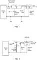
- FIGS. 1-3Block diagrams of some components of blood fluid devices or systems are shown in FIGS. 1-3 .
- bloodmay be removed from a patient 10 and may be filtered via a first filter 20 to separate the blood into plasma and cell enriched blood.
- cell enriched bloodmeans blood from which some fluid or plasma component has been removed. During most processes described herein, the cell enriched blood will retain some fluid or plasma component and will remain flowable in the device or system.
- the first filter 20may be any filter configured to allow plasma to pass through the filter and to block cells or other large components from blood from passing through the filter.
- the first filter 20has a pore size between about 0.1 microns and about 0.65 microns.
- Such filterspreferably restrict or exclude passage of cells and other large components of blood, such as clotting factors.
- Such filtersare well known in the art and are readily available from manufactures such as Millipore, Pall, Asahi Kasei, and Gambro.
- the filtersare made from materials that are biocompatible, such as polyethylene, polypropylene, PMMA, polysulfone, polyethersulfone, cellulose, silicon, ceramic, and the like.
- the first filter 20comprises one or more membranes.
- the first filter 20comprises one or more hollow fibers.
- the separated or filtered plasmais filtered via a second filter 30 to remove fluid.
- fluidmay be removed by filter 30 as typically done in ultrafiltration, hemofiltration, hemodialysis, or hemodiafiltration devices. Examples of such devices or components thereof that may be employed in accordance with the teachings presented herein are well known in the art. It will be understood that peritoneal dialysis, where dialysate is introduced into the peritoneal cavity, may also be employed. In embodiments where the blood fluid removal device or system, or components thereof, are implanted, the removed fluid may be diverted to the patient's bladder.
- the second filter 30may be any filter suitable for removal of fluid from plasma.
- filters used in ultrafiltration, hemofiltration, hemodialysis, or hemodiafiltrationmay be employed.
- the second filter 30has a molecular weight cut off of between about 10,000 and about 100,000 Da.
- Such filtersshould restrict or exclude passage of larger components of plasma to pass through the filter, while allowing fluid and smaller components (e.g., less than 60,000 Da), such as urea, creatinine, and the like, to pass through the filter.
- Such filtersare well known in the art and are readily available from manufactures such as Gambro, Nipro, and Fresenius.
- the filtersare made from materials that are biocompatible, such as polysulfone, polyethersulfone, polyacrylonitrile, PMMA, and the like.
- the second filter 30comprises one or more membranes.
- the second filter 30comprises one or more hollow fibers.
- the reduced fluid plasmais combined with the cell enriched blood and returned to the patient 10.
- fluidmay be removed at too great of a rate or amount.
- replacement fluidRF
- replacement fluidmay be introduced to the patient's blood, cell enriched blood, plasma, reduced fluid plasma, or the like, before the reconstituted blood is returned to the patient. While not shown in FIGS. 2-3 , it will be understood that replacement fluid may be added as described and shown with regard to FIG 1 .
- Replacement fluidmay be tailored to adjust the pH, electrolyte concentrations, etc. so that blood returned to the patient has a desired composition.
- dialysatemay be employed to assist in removal of contaminants from the patient's plasma and in maintaining proper pH and electrolyte balance. Used dialysate and fluid removed from the blood may be diverted. In some embodiments, particularly where the blood fluid removal device or system or components thereof are wearable or implantable, the used dialysate and removed fluid, or a portion thereof, may be regenerated to produce fresh dialysate for re-use in the blood fluid removal process.
- REDYregenerative dialysis
- Nephrology 4:275-278, 1998which system may be employed or readily modified for use in embodiments described herein.
- Another system for regenerative dialysishas been described in US Provisional Patent Application Serial No. 61/480,532 ( US 2012-0273420 ), entitled ELECTROLYTE AND pH MONITORING FOR FLUID REMOVAL PROCESSES , filed on April 29, 2011. While not shown in FIGS. 1 and 3 , it will be understood that dialysate may be used in these embodiments as described and shown with regard to FIG 2 .
- plasmamay be contacted with a sorbent medium 40 to selectively remove components from the plasma to produce sorbed plasma, which may be combined with cell enriched blood and returned to the patient 10.
- a sorbent medium 40to selectively remove components from the plasma to produce sorbed plasma, which may be combined with cell enriched blood and returned to the patient 10.
- Selective removal of components from blood via a sorbentpresents challenges due to clotting. However, by prefiltering the blood (via the first filter 20 ), cells and clotting factors may be removed or reduced, allowing for more efficient use of the sorbent 40 with plasma.
- the sorbent medium 40may be configured to remove one or more waste or other products from plasma, such as urea, uric acid, ⁇ 2-microglobulin, creatinine, phosphate, or the like.
- the sorbent medium 40may include selective binding agents, such as antibodies, receptors, or the like, bound to membranes, fibers, particles, or the like to selectively remove targeted components from plasma.
- the sorbent mediummay be contained in a packed column or in the flow path between the first 20 and second 30 filters.
- the sorbent mediumcontains materials such zirconium oxide, zirconium phosphate, activated carbon, zeolites, zirconium silicate, polymer resins, and the like.
- the sorbent medium 40is included in a cartridge or other container or module.
- the plasmamay be passed through or along the sorbent 40 before (dashed lines) or after (solid lines) fluid is removed from the plasma. While not shown in FIGS. 1-2 , it will be understood that a sorbent may be similarly employed in those embodiments.
- some or all of the reduced fluid plasma that has passed through filter 30may be recirculated back through filter 30 in a recirculation loop.
- a valve (not shown) or flow restrictor downstream of the recirculation loop (not shown)may be used to direct reduced fluid plasma into the recirculation loop.
- a recirculation loopmay result in increased efficiency of fluid removal per surface area of filter 30.
- Use of a recirculation loopmay also allow the filtration rate across the first filter 20 to be relatively low, which may allow use of a membrane having a smaller surface area and a lower blood flow rate, which may allow use of less anticoagulant.
- the recirculation ratecould be relatively higher, e.g., between 50 ml/min. to 200 ml/min. to allow more efficient dialysis or filtration across the second membrane 30.
- a pump(not shown) may be employed.
- first 20 and second 30 filtersmay be disposed in a single housing, cartridge, container or the like. Sorbent 40 may also be disposed in the housing, cartridge, etc. Alternatively, the first 20 and second 30 filters and sorbent 40, if employed, may be disposed within separate housings, cartridges, containers, etc.
- the depicted devices 100have a housing 199 defining an interior.
- the interiorincludes a blood compartment 190 through which blood and cell enriched blood (e.g., as described above with regard to FIGS. 1-3 ) may flow, a plasma compartment 192 through which plasma, reduced fluid plasma or sorbed plasma (e.g., as described above with regard to FIGS. 1-3 ) may flow, and a fluid compartment 194, through which fluid removed from plasma or dialysate may flow.
- a first filter 110is disposed in the housing 199 and separates at least a portion of the blood compartment 190 from the plasma compartment 192.
- the first filter 110 in the embodimentsmay be a filter as described above with regard to the first filter 20 in FIGS. 1-3 . That is, the first filter 110 is configured to allow plasma components, but not cell or larger components, of blood to pass through the filter from the blood compartment 190 to the plasma compartment 192.
- the devices 100 in FIGS. 4-6include an inlet 101 and an outlet 105 in fluid communication with the blood compartment. Blood from the patient may be introduced into the device 100 via inlet 101 and cell enriched blood may exit the device 100 via outlet 105.
- the devices shown in FIGS. 4-6include a second filter 120 disposed in the interior defined by the housing 199 and separates at least a portion of the plasma compartment 192 from the fluid compartment 194.
- the second filter 120may be a filter as described above with regard to the second filter 30 in FIGS. 1-3 . That is, the second filter 120 is configured to allow fluid and other small or dissolved components, but not larger components, of plasma to pass through the filter 120 from the plasma compartment 192 to the fluid compartment 194.
- the devices depicted in FIGS. 4-6include an outlet 107 in fluid communication with the fluid compartment, and may optionally contain an inlet 103 in fluid communication with the fluid compartment, as depicted.
- the inlet 103may serve to allow dialysate and/or enrichment fluid to be introduced into the fluid compartment 194.
- Enrichment fluidmay be fluid with predetermined concentrations of electrolytes, buffers, etc. to adjust the pH or electrolyte concentration of plasma in plasma compartment 192 across filter 120.
- the outlet 107allows fluid removed from plasma, and used dialysate or enrichment fluid (if employed), to exit the device 100. While not shown, the plasma compartment 192 may have an inlet for purposes of priming.
- the device 100may also include an outlet 109 in communication with the plasma compartment 192.
- Reduced fluid plasmamay exit outlet 109 and be combined with cell enriched blood that exits outlet 105 prior to return to the patient.
- the reduced fluid plasma and cell enriched bloodmay be combined prior to exiting device 100 via exit 105.
- cell enriched bloodexits the blood compartment 190 via port or opening 191 and reduced fluid plasma exits the plasma compartment 192 via port or opening 193 to enter mixing chamber 197.
- ports or openings 191, 193contain one way valves to prevent fluid flow from the mixing chamber 197 to fluid compartment 190 or plasma compartment 192.
- the plasma and blood componentsmay be mixed or combined within mixing chamber prior to exiting via outlet 105.
- fluid from the fluid compartment 190is added prior to returning the blood to the patient.
- the fluidmay be introduced into mixing chamber 197 or may be introduced into to recombined blood, plasma or cell-enriched blood at any suitable point.
- lines or conduits in communication with outlets 105, 107may be used to divert a portion of fluid from fluid compartment 194 to blood before the blood is returned to the patient.
- a valve 183, flow restrictor, or the like,may be employed to divert all or a portion of the fluid to the blood.
- a sorbent medium 40may be disposed within the plasma compartment 192 to selectively remove components from plasma at the same time fluid is removed from plasma via second membrane 120.
- a sorbent medium 40may be disposed with the fluid compartment 194 to sorb components from fluid removed from the plasma. It may be desirable or advantageous to employ sorbent medium 40 in the fluid compartment 194 when fluid, or a portion thereof, is to be combined with blood prior to returning blood to the patient.
- the housing 199 or other components of device that may contact blood, plasma, or dialysateare preferably biocompatible or may be coated with a biocompatible material.
- the housingis formed from a metallic material, such as stainless steel (, or a suitable polymeric material, such as polystyrene, polycarbonate, or the like. If stainless steel components are employed, blood is preferably isolated from such components.
- FIGS. 7-14embodiments of devices 100 or components thereof are depicted.
- the depicted devices 100may operate in accordance with the general principles described above with regard to the devices of FIGS. 1-6 . It will be understood that, while not necessarily shown, components of the devices or systems depicted with regard to FIGS. 1-6 may be employed with regard to the devices of FIGS. 7-15 .
- the device 100may have inlets 101, 103 and outlets 105, 107, 109 as described above with regard to, e.g., FIGS. 4 and 6 .
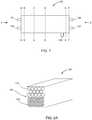
- the device 100 depicted in FIG. 7is in the form of a cartridge or module, but may be in any other suitable form. In embodiments, the device 100 is cylindrical (not shown).
- FIGS. 8-14are schematic sectional views of embodiments of the device 100 shown in FIG. 7 .
- FIGS. 8A and 10 -14various embodiments of devices taken through lines C-C and D-D of FIG. 7 are shown, with the section taken through line C-C shown in front.
- FIGS. 8B-8Eshow front views (8B) and back views (8C-E) of sections of embodiments of manifold 150 taken through lines A-A (8B) and B-B (8C-E) of FIG. 7 .
- FIGS. 8F-8Ishow back views (8G) and front views (8F, H, I) of embodiments of manifold 170 taken through lines E-E (8G) and F-F (8F, H, I ).
- the depicted blood fluid removal device 100includes a plurality of hollow large pore fibers 110 configured to allow plasma components, but not cell components, of blood to pass.
- the large pore fibers 110may function as first filter 110 as discussed above with regard to FIG. 5 .
- Bloodmay be introduced into lumens of the porous fibers 110 (and thus the lumens of the fibers 110 would constitute the blood compartment 190 as described above with regard to FIG. 5 ).
- Plasmamay pass through the pores of the fibers 110 and be located exterior to the fibers (and thus at least a portion of the plasma compartment 192 as described above with regard to FIG. 5 would be located exterior to the large pore fibers 110 in FIG. 8A ).
- the device 145preferably includes a dividing member 145, such as a wall (e.g., a wall impermeable by blood), to separate the large pore fibers 110 from the small pore fibers 120 and to isolate compartment containing fibers 110.
- a dividing member 145such as a wall (e.g., a wall impermeable by blood), to separate the large pore fibers 110 from the small pore fibers 120 and to isolate compartment containing fibers 110.
- the small pore fibers 120 depicted in FIG. 8Aare configured to allow fluid and smaller components, but not larger plasma components, of plasma to pass. Accordingly, the small pore fibers 120 may function as second filter 120 as discussed above with regard to FIG. 5 .
- the plasma compartmente.g., compartment 192 discussed with regard to FIG. 5
- fluid from the plasmamay cross the walls of the fibers to enter the lumen of the fibers 120.
- the lumen of the fibers 120constitutes the fluid compartment (e.g., compartment 194 discussed above with regard to FIG. 5 ).
- the device 100preferably does not include dividing member 145, if the blood compartment is defined by the lumens of the large pore fibers 110.
- plasma from blood in the lumen of the large fiber 110may flow through the wall of the fiber 110 to the exterior of the large fibers 110 and surround the small fibers 120 so that fluid may flow into the lumens of the small fibers 120 for removal.
- plasmais directed into the lumens of the small pore fibers 120.
- the plasma compartmentis defined by the lumens of the porous fibers 120.
- the fluid compartmentwould then be exterior to the small pore fibers 120.
- FIGS. 8B-Kshow various embodiments of sections of manifolds 150 (e.g. encompassing at least the portion of the device in FIG. 7 between lines A-A and B-B ), that may be used to direct blood or dialysate, if used, to an appropriate compartment (i.e., blood or fluid compartment) of a device as described with regard to FIG. 8A .
- the front of the manifold 150e.g., section A-A of FIG. 7 when viewed in the direction indicated by arrow Y
- the first opening 102is in communication with port or inlet 101 depicted in FIG. 7 for introducing blood into the device.
- the second opening 104is in communication with port or inlet 103 depicted in FIG. 7 for introducing dialysate into the device.
- FIGS. 8C-Gshow alternative back portions (e.g., section B-B of FIG. 7 when viewed in the direction indicated by arrow Z ) of the manifold of FIG. 8B for appropriately directing the blood or dialysate into the device of FIG. 8A .
- the manifoldmay have a plurality of openings 111 in communication with opening 102 of FIG. 8B .
- the openings 111are configured and positioned to allow blood to flow into the lumens of the large pore fibers 110 depicted in FIG. 8A .
- the manifoldmay have a plurality of openings 121 in communication with opening 102 of FIG. 8B .
- the openings 121are configured and positioned to allow dialysate to flow into the lumens of the small pore fibers 120 depicted in FIG. 8A .
- the fibersmay be sealed to the manifold such that the lumens of the fibers are in communication with the appropriate openings 111, 121 of the manifold 150.
- the fibersmay be sealed to the manifold in any suitable manner, such as via a polymeric material (e.g., an epoxy resin or the like).
- the open area 112 of the manifoldwhich is in communication with opening 102 depicted in FIG. 8B , is configured and positioned to allow blood to flow external to large pore fibers 110 of FIG. 8A .
- solid elements 113 of manifold 150are sealed to ends of large pore fibers 110 (e.g. via an appropriate polymer) to isolate the lumens of the large pore fibers from the blood.
- the ends of the large pore fibersmay be sealed, such as by potting in the ends with an appropriate polymeric material, such as an epoxy resin.
- the back portion of the manifold 150 in communication with opening 102(see, FIG. 8B ), which is the upper portion in FIG. 8E , may include one large opening 112.
- the open area 122 of the manifoldwhich is in communication with opening 104 depicted in FIG. 8B , is configured and positioned to allow dialysate to flow external to small pore fibers 120 of FIG. 8A .
- solid elements 127 of manifold 150are sealed to ends of small pore fibers 120 to isolate the lumens of the small pore fibers from the dialysate; e.g., as described above with regard to the large pore fibers with regard to blood.
- the open area 112may include one large opening 112 if the ends of the small pore fibers are sealed or potted.
- FIGS. 8H-8Idepict an embodiment of sections of manifolds 170 (e.g. encompassing at least the portion of the device in FIG. 7 between lines E-E and F-F ) that may be used to direct blood or fluid (or fluid and dialysate, if used) out of the device 100 shown in FIG. 8A , which is an embodiment of the device shown in FIG. 7 .
- the back of the manifold 170e.g., section F-F of FIG. 7 when viewed in the direction indicated by arrow Z
- the first opening 106is in communication with port or outlet 105 depicted in FIG. 7 for removal of cell enhanced blood from the device.
- FIG. 8Idepicts a front portion (e.g., section E-E of FIG. 7 when viewed in the direction indicated by arrow Y ) of manifold 170.
- the depicted manifold 170has a plurality of openings 113 in communication with opening 106 of FIG. 8H .
- the openings 113are configured and positioned to allow blood to flow from the lumens of the large pore fibers 110 depicted in FIG. 8A through the manifold 170 (and thus the fibers are sealed relative to the manifold such that the lumen of the fibers are in communication with the openings 113 ).
- the manifoldmay have a plurality of openings 123 in communication with opening 108 of FIG. 8H .
- the openings 123are configured and positioned to allow fluid or fluid and used dialysate to flow out of the lumens of the small pore fibers 120 depicted in FIG. 8A and through the manifold (and thus the fibers are sealed relative to the manifold such that the lumen of the fibers are in communication with the openings 123 ).
- FIGS. 8J-Kshow alternative front portions (e.g., section E-E of FIG. 7 when viewed in the direction indicated by arrow Y ) of manifold 170, for which the back portion is shown in FIG. 8H , for appropriately directing the blood or fluid out of the device of FIG. 8A .
- the manifold 170may have an opening 113 in communication with opening 106 of FIG. 8H .
- the opening 113is configured and positioned to allow blood exterior to the lumens of the large pore fibers 110 depicted in FIG. 8A to flow through the manifold 170 through the opening 113 and out opening 106 (see FIG. 8H ).
- FIG. 8Hshow alternative front portions (e.g., section E-E of FIG. 7 when viewed in the direction indicated by arrow Y ) of manifold 170, for which the back portion is shown in FIG. 8H , for appropriately directing the blood or fluid out of the device of FIG. 8A .
- the manifold 170may have a plurality of diverter conduits 115 defining openings 116 through which plasma within pores of large pore fibers may be diverted into the lower portion of manifold and back into the device through opening 127 (and this the large pore fibers are sealed relative to conduits 115 such that the lumens of the fibers are in communication with openings 116 ).
- opening 127is formed around structural elements 125 of the manifold 170.
- the structural elementsdefine openings 123 in communication with opening 108 (see FIG. 8H ).
- the openings 123are configured and positioned to allow fluid or fluid and used dialysate to flow out of the lumens of the small pore fibers 120 depicted in FIG. 8A and through the manifold (and thus the small pore fibers are sealed relative to the structural elements 125 such that the lumens of the fibers are in communication with the openings 123 ).
- the open area 123 of the manifold 170which is in communication with opening 108 depicted in FIG. 8G , is configured and positioned to allow to dialysate from the outside of the small pore fibers 120 of FIG. 8A to flow through the manifold and out of the device.
- the open area 123is defined around structural elements 125 which define openings 127, through which plasma is configured to flow back into the device.
- the top portion of the manifold 170 in FIG. 8Kis the same as the top portion of the manifold in FIG. 8J .
- the manifold 170is configured such that plasma within the diverter conduits 115 is diverted back into device through open area 123 (e.g., openings 116 defined by structural members 115 are in communication with open area 123.
- manifold configurations other than those depicted in FIGS. 8B-Kmay be used to direct blood, fluid or dialysate to, or from, appropriate compartments of a blood fluid removal device 100 as depicted in FIG. 8A .
- large pore fibers 110 and small pore fibers 120are interspersed.
- Such an arrangement of fibersmay be advantageous when the space surrounding the fibers is the plasma compartment (the blood compartment is within the lumens of the large pore fibers 110, and the fluid compartment is within the lumens of the small pore fibers 120 ).
- Any suitable manifoldmay be used to direct blood and dialysate, if used, into or out of the large 110 and small 120 pore fibers.
- FIG. 10illustrates an alternative embodiment, where a membrane 110 is disposed with and across the housing of the device 100.
- the membranes 100are configured to allow plasma components, but not cell components, of blood to pass.
- the membrane 110may function as first filter 110 as discussed above with regard to FIG. 5 .
- bloodmay be introduced between the membranes 110 (and thus the space between the membranes 110 would constitute the blood compartment 190 as described above with regard to FIG. 5 ).
- Plasmamay pass through the membranes 110 and surround the small pore fibers 120, which may be small pore fibers as described above.
- fluidmay pass from plasma into the lumens of the hollow porous fibers 120 or dialysate may be introduced into the lumens of the hollow porous fibers, e.g. as discussed above with regard to other embodiments.
- the device 100may include membranes 110 that span the housing of the device and define the blood compartment B. Plasma may pass the membranes 110.
- the plasma compartment Pis defined between membranes 110 and membranes 120.
- Membranes 120also span the housing and are configured to allow fluid and smaller components, but not larger plasma components, of plasma to pass. Accordingly, the membranes 120 may function as second filter 120 as discussed above with regard to FIG. 5 .
- the fluid compartmentis defined between the housing of the device and membranes 120 (at the topmost and bottommost portions of the depicted device).
- FIG. 12Another embodiment is depicted in FIG. 12 , where blood is passed through lumens of large pore fibers 110 (e.g., as described above with regard to other embodiments). Plasma may pass through the porous walls of the fibers 110 to the space exterior to the fibers. Fluid from plasma may cross membrane 120 which is disposed across the housing of the device 100.
- FIG. 13Yet another embodiment is depicted in FIG. 13 .
- the device 100 depicted in FIG. 13is similar to the device depicted in FIG. 12 .
- the device 100 depicted in FIG. 14includes sorbent material 130 disposed in the plasma compartment.
- Sorbent material 130may be sorbent material described above with regard to FIG. 3 . While not shown, it will be understood that sorbent may be similarly placed in the plasma compartment of any of the other embodiments of devices 100 described above.
- FIGS. 9-13it will be understood that suitable manifolds may be employed to direct blood, fluid, dialysate, or plasma to or from the appropriate location or compartment of the device. It will also be understood that the embodiments depicted in FIGS. 8-13 are merely illustrative of possible embodiments and that combinations of elements depicted in these figures, which combinations are not shown or described herein, may be readily made and are contemplated. It will be further understood that modification of elements described herein may be made without departing from the scope of the devices and systems defined by the claims.
- first 110 and second 120 filtersare disposed within interior 180 of housing 199 of device 100.
- the filters 110, 120may be fibers or membranes, but are shown as fibers for purposes of convenience.
- the interior 180may be divided into first 182 and second 184 chambers in some embodiments (see, e.g., FIGS. 15-17 ).
- "B"refers to blood within the blood compartment
- "P”refers to plasma within the plasma compartment
- "D”refers to dialysate in the fluid compartment. It will be understood that, while dialysate is shown in each of FIGS. 15-18 , similar principles apply when dialysate is not used.
- blood Bis shown in a lumen of a large pore fiber 110.
- Plasma Pmay cross the wall of the porous fiber 110 and enter the space with the interior 180 of the housing 199 surrounding the large pore fibers 110 and the small pore fibers 120.
- Dialysate Dflows through the lumen of the small pore fiber 120.
- Fluid and other agentsmay exchange between plasma P and dialysate D through the walls of the porous fiber 120.
- plasma Pwhich may also have adjusted pH, buffers, electrolytes, etc. if dialysate is used as shown.
- the reduced fluid plasma Pmay then be combined with cell enriched blood B that flows through the device 100 before being returned to a patient, or the plasma, or some percentage thereof, may be recirculated and become equilibrated with the blood in terms of protein content, but still allow fluid to transfer from the blood to the plasma and out fiber 120.
- the arrow between B and Pis shown as bidirectional because plasma, or components thereof, may cross between plasma and blood compartments, with equilibrium being driven by pressure and concentration gradients.
- blood Bis introduced exterior to the large pore fiber 110 in the first chamber 182.
- Plasma Pmay flow across the wall and into the lumen of the porous fiber 110.
- the plasma Pis then directed to exterior to the small pore fiber 120 in the second chamber 184, e.g., via a manifold as described above, where fluid from plasma P may cross the wall, and enter the lumen, of the porous fiber 120.
- dialysate Dmay flow through the lumen of the small pore fiber 120 if desired.
- blood Bis introduced into the lumen of the large pore fiber 110 in the first chamber 182.
- Plasma Pmay flow across the wall and into the first chamber 182 in the space surrounding the porous fiber 110.
- the plasma Pis then directed to into the lumen of the small pore fiber 120 in the second chamber 184, e.g., via a manifold as described above, where fluid from plasma P may cross the wall, and enter the second chamber 184 in the space surrounding the porous fiber 120.
- dialysate Dmay flow the second chamber 184 in the space surrounding the small pore fiber 120 if desired.
- blood Bis introduced exterior to the large pore fiber 110 in the first chamber 182.
- Plasma Pmay flow across the wall and into the lumen of the porous fiber 110.
- the plasma Pis then directed to into the lumen of the small pore fiber 120 in the second chamber 184, e.g., via a manifold as described above, where fluid from plasma P may cross the wall, and enter the second chamber 184 in the space surrounding the porous fiber 120.
- dialysate Dmay flow the second chamber 184 in the space surrounding the small pore fiber 120 if desired.
- blood Bis introduced into lumens of the large pore fibers 110.
- Plasma Pmay flow across the wall of the large pore fibers 110 and into in the first chamber 182.
- the plasma Pis then directed to into the lumen of the small pore fiber 120 in the second chamber 184, e.g., via a manifold as described above, where fluid from plasma P may cross the wall, and enter the second chamber 184 in the space surrounding the porous fiber 120.
- dialysate Dmay flow the second chamber 184 in the space surrounding the small pore fiber 120 if desired.
- FIGS. 14-18represent only some examples of ways in which plasma may be separated from blood and fluid may be removed from the plasma and that other ways of accomplishing separating plasma from blood prior to fluid removal from plasma are contemplated herein. It will also be understood that sorbent may be placed at any suitable location in the plasma compartment, either upstream or downstream of fluid removal.
- sorbentmay be place in the lumens of the fibers; (ii) if blood is introduced external to large pore fibers so that plasma flows into the lumens of the fibers, sorbent may be place in the lumens of the fibers; (ii) if blood is introduced into the lumens of the large pore fibers, sorbent may be placed in the space external to the large pore fibers; (iii) if plasma is introduced into lumens of the small pore fibers, sorbent may be placed in the lumens of the small pore fibers; (iv) if plasma is introduced into the space surrounding the small pore fibers, sorbent may be placed in the space around the small pore fibers; (v) etc.
- FIG. 19an overview of a scheme for separating plasma from blood and removing fluid from the separated plasma is shown. Any suitable device or system for accomplishing this scheme may be used in accordance with the teachings herein.
- blood from the patient 200is filtered to separate cell enriched blood 210 and plasma 220.
- the plasma 220is then filtered or dialyzed (and optionally sorbed) to remove fluid 230 from the plasma and leave reduced fluid plasma 240.
- the reduced fluid plasma 240may be further filtered or contacted with a sorbent to produce sorbed plasma 250.
- the reduced fluid plasma 240 or sorbed plasma 250is then combined with the cell enriched blood 210 and returned to the patient 260.
- the reduced fluid plasmais recirculated and further subjected to filtering, dialysis or sorption.
- Replacement or enrichment fluid RFmay be added to reduced fluid or sorbed plasma or cell-enriched blood prior to returning the reduced-fluid blood to the patient. While not shown, it will be understood that some or all of the fluid 230 removed from plasma 220 may be returned to blood (e.g., added to cell enriched blood 210 or reduced fluid plasma 240 ) prior to returning to the patient 260. In such situations it may be desirable to remove waste products from the fluid 230 by sorption.
- the methodincludes separating blood in a plasma component and a blood component ( 300 ); e.g. with a large pore filter.
- the methodfurther includes subjecting the plasma component to a fluid removal process ( 310 ), such as ultrafiltration or hemodialysis via a small pore filter.
- the separated blood component and the plasma with fluid removedare combined ( 320 ) and returned to the patient ( 330 ).
- the reduced fluid plasmamay be recirculated to undergo further fluid removal as indicated by the dashed lines in FIG. 20 .
- the method in FIG. 21is similar to the method depicted in FIG. 20 , but further includes removing elements from plasma ( 340 ). While this is shown in FIG. 21 as occurring after the plasma is subjected to the fluid removal process ( 310 ), it will be understood that elements may be removed from plasma ( 340 ) prior to or during the fluid removal process ( 310 ).
- the dashed lines in FIG. 21indicate optional recirculation of reduced-fluid plasma, or a percentage thereof (e.g., as described with regard to FIG. 20 ).
- a medical devicein a first aspect, includes (i) a housing defining an interior, wherein the interior has a blood compartment, a plasma compartment, and a fluid compartment; (ii) a first filter disposed in the interior of the housing, wherein the first filter separates at least a portion of the blood compartment from at least a portion of the plasma compartment and wherein the first filter is configured to allow plasma components, but not cell components, of blood to pass through the first filter from the blood compartment to the plasma compartment; and (iii) a second filter disposed in the interior of the housing, wherein the second filter separates at least a portion of the plasma compartment from at least a portion of the fluid compartment, wherein the second filter is configured to allow fluid and small molecules, but not larger components, to pass through the second filter from the plasma compartment to the fluid compartment.
- a second aspectis a device of the first aspect, further comprising: (i) an inlet in communication with the blood compartment; (ii) a first outlet in communication with the blood compartment; and (iii) a second outlet in communication with the fluid compartment.
- a third aspectis a device of the second aspect, wherein the first outlet is in communication with the plasma compartment.
- a fourth aspectis a device of the second aspect, further comprising a third outlet in communication with the plasma compartment.
- a fifth aspectis a device of any of the first four aspects, further comprising a dialysate inlet in communication with the fluid compartment.
- a sixth aspectis a device of any of the first five aspects, wherein the first filter comprises a porous fiber having a lumen, and wherein at least a portion of the blood compartment is defined by the lumen of the first filter porous fiber.
- a seventh aspectis a device according to the sixth aspect, wherein the second filter comprises a porous fiber having a lumen, and wherein at least a portion of the fluid compartment is defined by the lumen of the second filter porous fiber.
- An eighth aspectis a device according to the sixth aspect, wherein the second filter comprises a porous fiber having a lumen, and wherein at least a portion of the plasma compartment is defined by the lumen of the second filter porous fiber.
- a ninth aspectis a device according to the eighth aspect, wherein a first portion of the plasma compartment is defined by the exterior of the first filter porous fiber, and wherein the device further comprises a manifold having at least one opening in communication with the first portion of the plasma compartment and the lumen of the second filter porous fiber.
- a tenth aspectis a device according to the sixth aspect, wherein the second filter comprises a membrane.
- An eleventh aspectis a device according to the tenth aspect, wherein the membrane is disposed across the housing.
- a twelfth aspectis a device according to any of the first five aspects, wherein the first filter comprises a porous fiber having a lumen, and wherein at least a portion of the plasma compartment is defined by the lumen of the first filter porous fiber.
- a thirteenth aspectis a device according to the twelfth aspect, wherein the second filter comprises a porous fiber having a lumen, and wherein at least a portion of the fluid compartment is defined by the lumen of the second filter porous fiber.
- a fourteenth aspectis a device according to the twelfth aspect, wherein the second filter comprises a porous fiber having a lumen, and wherein at least a portion of the plasma compartment is defined by the lumen of the second filter porous fiber.
- a fifteenth aspectis a device according to the fourteenth aspect, further comprising a manifold having at least one opening in communication with the lumen of the first filter porous fiber and the lumen of the second filter porous fiber.
- a sixteenth aspectis a device according to the twelfth aspect, wherein the second filter comprises a membrane.
- a seventeenth aspectis a device according to the sixteenth aspect, wherein the membrane is disposed across the housing.
- An eighteenth aspectis a device according to any of the first five aspects, wherein the first filter comprises a membrane.
- a nineteenth aspectis a device according to the eighteenth aspect, wherein the membrane is disposed across the housing.
- a twentieth aspectis a device according to the eighteenth or nineteenth aspects, wherein the second filter comprises a porous fiber having a lumen, and wherein at least a portion of the fluid compartment is defined by the lumen of the second filter porous fiber.
- a twenty-first aspectis a device according to the eighteenth or nineteenth aspects, wherein the second filter comprises a porous fiber having a lumen, and wherein at least a portion of the plasma compartment is defined by the lumen of the second filter porous fiber.
- a twenty-second aspectis a device according to according to the eighteenth or nineteenth aspects, wherein the second filter comprises a membrane.
- a twenty-third aspectis a device according to the twenty-second aspect, wherein the membrane is disposed across the housing.
- a twenty-fourth aspectis a device according to any of the first twenty-three aspects, further comprising a sorbent disposed within the plasma compartment, wherein the sorbent is configured to selectively absorb one or more components from plasma.
- a twenty-fifth aspectis a device according to any of the first twenty-four aspects, wherein the device is in the form of a cartridge.
- a twenty-sixth aspectis a system including (i) a device according to any of aspects 1-25, wherein the device comprises the third outlet of aspect 4; and (ii) a sorbent medium in fluid communication with the plasma compartment of the device and downstream of the third outlet.
- a twenty-seventh aspectis a system according to the twenty-sixth aspect, further comprising a manifold having a first inlet in communication with the blood compartment of the device, a second inlet in communication with the plasma compartment of the device and downstream of the sorbent medium, and an outlet in communication with the first and second manifold inlets.
- a twenty-eighth aspectis a method including (i) separating a patient's blood into a plasma component and a cell component; (ii) dialyzing the plasma component to obtain dialyzed plasma; and (iii) combining the cell component and the dialyzed plasma to generate dialyzed blood.
- a twenty-ninth aspectis a method according to the twenty-eighth aspect, further comprising introducing the dialyzed blood into the patient.
- a thirtieth aspectis a method according to the twenty-eighth or twenty-ninth aspects, further comprising removing selected elements from the plasma component via a sorbent.
- a thirty-first aspectis a method according to the twenty-eighth or twenty-ninth aspects, further comprising removing selected elements from the dialyzed plasma via a sorbent.
- a thirty-second aspectis a method including (i) separating a patient's blood into a plasma component and a cell component; (ii) filtering fluid from the plasma component to obtain reduced fluid plasma; and (iii) combining the cell component and the reduced fluid plasma to generate filtered blood.
- a thirty-third aspectis a method according to the thirty-second aspect, further comprising introducing the filtered blood into the patient.
- a thirty-fourth aspectis a method according to the thirty-second or thirty-third aspect, further comprising removing selected elements from the plasma component via a sorbent.
- a thirty-fifth aspectis a method according to the thirty-second or thirty-third aspect, further comprising removing selected elements from the filtered plasma via a sorbent.
- pumps, valves, or other componentsthat may be employed in the field of hemodialysis, ultrafiltration, or the like, while not shown, may be used in the devices, systems and methods described herein to facilitate the removal of fluid from blood or plasma; to drive flow of blood, plasma, replacement fluid, dialysate, enrichment fluid, or the like; or the like.
Landscapes
- Health & Medical Sciences (AREA)
- Heart & Thoracic Surgery (AREA)
- Engineering & Computer Science (AREA)
- Chemical & Material Sciences (AREA)
- Urology & Nephrology (AREA)
- Chemical Kinetics & Catalysis (AREA)
- Vascular Medicine (AREA)
- Anesthesiology (AREA)
- Biomedical Technology (AREA)
- Hematology (AREA)
- Life Sciences & Earth Sciences (AREA)
- Animal Behavior & Ethology (AREA)
- General Health & Medical Sciences (AREA)
- Public Health (AREA)
- Veterinary Medicine (AREA)
- Water Supply & Treatment (AREA)
- Emergency Medicine (AREA)
- Analytical Chemistry (AREA)
- External Artificial Organs (AREA)
Description
- The present disclosure relates generally to devices, systems and methods for hemodialysis, ultrafiltration, and the like.
- Blood fluid removal processes, such as hemodialysis and ultrafiltration, typically employ a filter or membrane across which fluid, and some waste products, may be removed from blood. The blood, with reduced fluid or waste products, is then returned to the patient.
EP 0264695 teaches an apparatus for filtering and cleaning blood taken from a patient and returning the filtered blood to the patient. - The present invention is defined by the appended claims.
- This disclosure, among other things, describes devices, systems and methods that include pre-filtering blood to separate plasma from cellular components of blood and subjecting the plasma to at least one additional fluid removal process. Pre-filtering reduces or eliminates cells and clotting factors that contact the filter used to remove fluid from the plasma, thereby reducing the likelihood of fouling secondary filtering systems, which may increase longevity of such secondary filtering systems or components thereof. The devices, systems and processes described herein may allow for lower concentrations of anticoagulants to be used in the blood fluid removal process, and thus may reduce the amount of anticoagulants present in blood returned to the patient.
- In embodiments described herein, a method includes separating a patient's blood into a plasma component and a cell component. Fluid is then removed from the plasma component to obtain a reduced-fluid plasma. The fluid may be removed by dialysis, ultrafiltration, or the like. The reduced-fluid plasma may be combined with the cell component and may be returned to the patient. In embodiments, at least some of the reduced-fluid plasma is recirculated for additional fluid removal or treatment through the dialysis process, the ultrafiltration process, or the like. The plasma or reduced fluid plasma may be contacted with a sorbent to remove or reduce the concentration of one or more additional components of the plasma or reduced-fluid plasma.
- In embodiments described herein, a device includes (i) a housing defining an interior, wherein the interior has a blood compartment, a plasma compartment, and a fluid compartment; (ii) a first filter disposed in the interior of the housing, and (iii) a second filter disposed in the interior of the housing. The first filter separates at least a portion of the blood compartment from at least a portion of the plasma compartment. The first filter is configured to allow plasma components, but not cell components, of blood to pass through the first filter from the blood compartment to the plasma compartment. The second filter separates at least a portion of the plasma compartment from at least a portion of the fluid compartment. The second filter is configured to allow fluid and small molecules, but not larger components, to pass through the second filter from the plasma compartment to the fluid compartment. The device may include a sorbent in either the plasma or reduced-fluid compartment to remove or reduce the concentration of selected components of the plasma. In embodiments, a system including the device includes a sorbent with which the plasma or reduced-fluid plasma may be contacted.
- One or more embodiments of the systems, devices and methods described herein may provide one or more advantages over prior systems, devices and methods for blood fluid removal in patients. For example, the processes described herein may result in reduced likelihood of fouling of membranes, and thus may allow for use of lowered concentrations of anticoagulant. By pre-filtering blood cells and other large components, such as clotting factors, the efficiency of the blood fluid removal process may be increased and may allow for a reduction in the size of the fluid removal filter employed. Pre-filtering blood cells and other large components may allow more ready use of sorbents for selective removal of components from plasma, where the presence of cells and clotting factors may result in fouling, and inefficient use, of the sorbent. These and other advantages will be apparent to those of skill in the art upon reading the following detailed description.
- In one or more embodiments of the systems, devices and methods described herein, one or more efficiencies may be obtained by having additional filtration systems or sorbent systems for use in the same compartments.
- The accompanying drawings, which are incorporated into and form a part of the specification, illustrate several embodiments of the present disclosure and, together with the description, serve to explain the principles of the disclosure. The drawings are only for the purpose of illustrating embodiments of the disclosure and are not to be construed as limiting the disclosure.
FIGS. 1-3 are schematic block diagrams showing interaction of components of embodiments of blood fluid removal devices or systems with a patient illustrating flow of blood and fluid.FIGS. 4-6 are schematic block diagrams of embodiments of blood fluid removal devices in accordance with embodiments described herein.FIG 7 is a schematic diagram of a side view of an embodiment of a blood fluid removal module in accordance with embodiments described herein.FIGS. 8A-J are schematic views of various embodiments of the module ofFIG. 7 , taken through various sections.FIGS. 9-13 are partial sectional views of alternative embodiments of a blood fluid removal module taken through lineC-C ofFIG. 7 .FIGS. 14-18 are schematic diagrams illustrating principles by which various embodiments of devices, systems and methods described herein may operate.FIG. 19 is a schematic overview for removing plasma from blood and removing fluid from the plasma according to embodiments described herein.FIGS. 20-21 are flow diagrams illustrating embodiments of methods described herein.- The schematic drawings presented herein are not necessarily to scale. Like numbers used in the figures refer to like components, steps and the like. However, it will be understood that the use of a number to refer to a component in a given figure is not intended to limit the component in another figure labeled with the same number. In addition, the use of different numbers to refer to components is not intended to indicate that the different numbered components cannot be the same or similar.
- In the following detailed description, reference is made to the accompanying drawings that form a part hereof, and in which are shown by way of illustration several embodiments of devices, systems and methods. It is to be understood that other embodiments are contemplated and may be made without departing from the scope of the present invention as defined by the claims. The following detailed description, therefore, is not to be taken in a limiting sense.
- All scientific and technical terms used herein have meanings commonly used in the art unless otherwise specified. The definitions provided herein are to facilitate understanding of certain terms used frequently herein and are not meant to limit the scope of the present disclosure.
- As used in this specification and the appended claims, the singular forms "a", "an", and "the" encompass embodiments having plural referents, unless the content clearly dictates otherwise.
- As used in this specification and the appended claims, the term "or" is generally employed in its sense including "and/or" unless the content clearly dictates otherwise.
- As used herein, "have", "having", "include", "including", "comprise", "comprising" or the like are used in their open ended sense, and generally mean "including, but not limited to."
- "Consisting essentially of", as it relates to a device, system, or method, means that the device, system, or method includes only the recited components or steps of the device, system, or method and, optionally, other components or steps that do not materially affect the basic and novel properties of the device, system, or methods.
- "Consisting of' and "consisting essentially of' are subsumed within "comprising." For example, a filter comprising a porous membrane may be a filter consisting essentially of, or consisting of, the porous membrane.
- Any direction referred to herein, such as "top," "bottom," "left," "right," "upper," "lower," "above," below," and other directions and orientations are described herein for clarity in reference to the figures and are not to be limiting of an actual device or system or use of the device or system. Many of the devices or systems described herein may be used in a number of directions and orientations.
- As used herein, a "blood fluid removal process," or the like, refers to a process from which fluid is removed from blood, or one or more components thereof, such as plasma. Often the blood, or component thereof, is returned to a patient after the fluid is removed. In many cases, the blood, or component thereof, is also cleaned; i.e., waste products are removed from the blood, or component thereof, and cleaned blood, or component thereof, is returned to the patient. Examples of blood fluid removal processes include ultrafiltration, hemofiltration, hemodialysis, hemodiafiltration, peritoneal dialysis and the like. It will be understood that, during some of these processes, fluid may be introduced to blood, or components thereof, before it is returned to the patient, and thus the returned blood, or components thereof, may not have a reduced fluid volume even though it has been subjected to a blood fluid removal process. Any patient for which a blood fluid removal process is indicated may benefit from the devices, systems and methods described herein.
- As used herein, a "patient for which a blood fluid removal process is indicated" is a patient that has undergone, is undergoing, or is likely to undergo at least one blood fluid removal process wherein the blood is further processed and returned to the patient. In general, such patients are fluid overloaded patients, such as patients suffering from heart failure, chronic kidney disease, or acute kidney failure. Often such patients are stage 3 to stage 5 chronic kidney disease patients, are often unresponsive or under-responsive to diuretics, or the like.
- As used herein, "plasma," "plasma component of blood," or the like, refer to a liquid component of blood in which some or all cells or other large components, such as components greater than about 0.2 microns (e.g., greater than about 0.5 microns or greater than about 1 micron), have been removed. In embodiments, cells or other large components are removed by filtration; e.g., by passing across a filter having a molecular weight cutoff of about 500,000 Da.
- As used herein, "reduced-fluid plasma" refers to plasma from which at least some fluid has been removed or which has been subjected to a blood fluid removal process.
- As used herein, "cell-enriched blood" means blood from which at least some fluid, such as plasma, has been removed so that the concentration of cells in the remaining blood is enriched relative to the blood prior to fluid removal.
- As used herein, "filtered blood" means blood that has been subjected to a blood fluid removal process or blood that has been recombined with components of blood, such as plasma, that have been subjected to a blood fluid removal process.
- As used herein, a "cell component" of blood is a component of blood that retains cells when plasma has been removed the blood. The cell component of blood may include plasma. For example, the cell component may retain some plasma when the blood has been separated into a cell component and a plasma component.
- As used herein, "filtering fluid" means subjecting the fluid, such as plasma or blood, to a blood fluid removal process.
- As used herein, "dialyzed plasma" means plasma that has been subjected to a dialysis procedure, such as hemodialysis, hemodiafiltration, or the like.
- As used herein, "dialyzed blood" means blood that has been subjected to a dialysis procedure or blood that contains components, such as plasma, that have been subjected to a dialysis procedure. For example, blood that contains dialyzed plasma is dialyzed blood for the purposes of this disclosure.
- As used herein, a "porous fiber" is a membrane having a body forming a lumen, wherein the body contains pores within a size range that allow for passage of some solutes across the membrane through the pores but which restrict passage of other solutes across the membrane. The pores may be a series of interconnected voids formed in the body. In some embodiments, the membrane is configured to allow passage of plasma through the pores, but to restrict passage of cellular components of blood.
- As used herein, a "sorbent" is a substance that has the property to collect molecules of another substance by sorption; .e.g., by adsorption or absorption. A sorbent medium is a sorbent through, or around, which a substance, such as blood or plasma, may be passed so that molecules from the substance may be sorbed to the sorbent medium.
- As used herein, in the context of a blood fluid removal device, system, or components thereof, "blood compartment" is an enclosed space in which blood or cell-enriched blood is contained. Typically, at least a portion of the blood compartment is defined by a first filter configured to selectively allow plasma, but not cellular components of blood, to pass.
- As used herein, in the context of a blood fluid removal device, system, or components thereof, "plasma compartment" is an enclosed space in which plasma that has been separated from blood is contained. Typically, at least a portion of the plasma compartment is defined by a first filter that selectively allows plasma, but not cellular components of blood, to pass. At least a portion of the plasma compartment may be defined by second filter configured to allow smaller molecules (such as molecules less than about 60,000 Da), but not larger molecules (such as molecules greater than about 60,000 Da), to pass.
- As used herein, a "first filter" that separates a blood compartment from a plasma compartment is a membrane, which may be a porous fiber, configured to allow selective passage of plasma, but not cellular components of blood, across the membrane.
- As used herein, a "second filter" that separates a plasma compartment from a fluid compartment is a membrane, which may be a porous fiber, configured to allow selective passage of small molecules, but not larger molecules, across the membrane. In embodiments, the membrane is configured to allow selective passage of molecules of less than about 60,000 Da, but generally not molecules larger than about 60,000 Da.
- This disclosure, among other things, relates to devices, systems and methods that pre-filter blood to separate plasma from larger components, including cells. The plasma may then be subjected to a fluid removal process. By subjecting plasma, rather than blood, to a fluid removal process, the likelihood of fouling the blood fluid removal filter is reduced, which may increase the efficiency of fluid removal, may allow for a reduction in overall filter size, or may allow for reduced concentrations of anticoagulants to be used. Further, the separated plasma may be more amenable to sorbent treatment than blood, which may tend to clot and foul sorbents configured to selectively remove components from blood.
- Any suitable device or system for removing fluid, or fluid and contaminants, from blood may be used in accordance with the teachings presented herein. The devices, or components thereof, may be traditional large console-type, wearable, or implantable.
- Block diagrams of some components of blood fluid devices or systems are shown in
FIGS. 1-3 . As shown in, e.g.,FIG. 1 blood may be removed from apatient 10 and may be filtered via afirst filter 20 to separate the blood into plasma and cell enriched blood. As used herein, "cell enriched blood" means blood from which some fluid or plasma component has been removed. During most processes described herein, the cell enriched blood will retain some fluid or plasma component and will remain flowable in the device or system. - The
first filter 20 may be any filter configured to allow plasma to pass through the filter and to block cells or other large components from blood from passing through the filter. In embodiments, thefirst filter 20 has a pore size between about 0.1 microns and about 0.65 microns. Such filters preferably restrict or exclude passage of cells and other large components of blood, such as clotting factors. Such filters are well known in the art and are readily available from manufactures such as Millipore, Pall, Asahi Kasei, and Gambro. Preferably, the filters are made from materials that are biocompatible, such as polyethylene, polypropylene, PMMA, polysulfone, polyethersulfone, cellulose, silicon, ceramic, and the like. In embodiments, thefirst filter 20 comprises one or more membranes. In some embodiments, thefirst filter 20 comprises one or more hollow fibers. - Still with reference to
FIGS. 1-3 , the separated or filtered plasma is filtered via asecond filter 30 to remove fluid. By way of example, fluid may be removed byfilter 30 as typically done in ultrafiltration, hemofiltration, hemodialysis, or hemodiafiltration devices. Examples of such devices or components thereof that may be employed in accordance with the teachings presented herein are well known in the art. It will be understood that peritoneal dialysis, where dialysate is introduced into the peritoneal cavity, may also be employed. In embodiments where the blood fluid removal device or system, or components thereof, are implanted, the removed fluid may be diverted to the patient's bladder. - The
second filter 30 may be any filter suitable for removal of fluid from plasma. By way of example, filters used in ultrafiltration, hemofiltration, hemodialysis, or hemodiafiltration may be employed. In embodiments, thesecond filter 30 has a molecular weight cut off of between about 10,000 and about 100,000 Da. Such filters should restrict or exclude passage of larger components of plasma to pass through the filter, while allowing fluid and smaller components (e.g., less than 60,000 Da), such as urea, creatinine, and the like, to pass through the filter. Such filters are well known in the art and are readily available from manufactures such as Gambro, Nipro, and Fresenius. Preferably, the filters are made from materials that are biocompatible, such as polysulfone, polyethersulfone, polyacrylonitrile, PMMA, and the like. In embodiments, thesecond filter 30 comprises one or more membranes. In some embodiments, thesecond filter 30 comprises one or more hollow fibers. - As shown in
FIGS. 1-3 , the reduced fluid plasma is combined with the cell enriched blood and returned to thepatient 10. With some processes, devices or systems, fluid may be removed at too great of a rate or amount. As shown inFIG. 1 , replacement fluid(RF) may be introduced to the patient's blood, cell enriched blood, plasma, reduced fluid plasma, or the like, before the reconstituted blood is returned to the patient. While not shown inFIGS. 2-3 , it will be understood that replacement fluid may be added as described and shown with regard toFIG 1 . Replacement fluid may be tailored to adjust the pH, electrolyte concentrations, etc. so that blood returned to the patient has a desired composition. - As shown in the embodiment depicted in
FIG 2 , dialysate may be employed to assist in removal of contaminants from the patient's plasma and in maintaining proper pH and electrolyte balance. Used dialysate and fluid removed from the blood may be diverted. In some embodiments, particularly where the blood fluid removal device or system or components thereof are wearable or implantable, the used dialysate and removed fluid, or a portion thereof, may be regenerated to produce fresh dialysate for re-use in the blood fluid removal process. One system for regeneration of dialysate is the REDY system, such as described inRoberts, M, "The regenerative dialysis (REDY) sorbent system," Nephrology 4:275-278, 1998, which system may be employed or readily modified for use in embodiments described herein. Another system for regenerative dialysis has been described inUS Provisional Patent Application Serial No. 61/480,532 US 2012-0273420 ), entitled ELECTROLYTE AND pH MONITORING FOR FLUID REMOVAL PROCESSES , filed on April 29, 2011. While not shown inFIGS. 1 and3 , it will be understood that dialysate may be used in these embodiments as described and shown with regard toFIG 2 . - Referring now to
FIG 3 , plasma may be contacted with asorbent medium 40 to selectively remove components from the plasma to produce sorbed plasma, which may be combined with cell enriched blood and returned to thepatient 10. Selective removal of components from blood via a sorbent presents challenges due to clotting. However, by prefiltering the blood (via the first filter20), cells and clotting factors may be removed or reduced, allowing for more efficient use of thesorbent 40 with plasma. Thesorbent medium 40 may be configured to remove one or more waste or other products from plasma, such as urea, uric acid, β2-microglobulin, creatinine, phosphate, or the like. Thesorbent medium 40 may include selective binding agents, such as antibodies, receptors, or the like, bound to membranes, fibers, particles, or the like to selectively remove targeted components from plasma. The sorbent medium may be contained in a packed column or in the flow path between the first20 and second30 filters. In embodiments, the sorbent medium contains materials such zirconium oxide, zirconium phosphate, activated carbon, zeolites, zirconium silicate, polymer resins, and the like. In embodiments, thesorbent medium 40 is included in a cartridge or other container or module. - As shown in
FIG. 3 , the plasma may be passed through or along thesorbent 40 before (dashed lines) or after (solid lines) fluid is removed from the plasma. While not shown inFIGS. 1-2 , it will be understood that a sorbent may be similarly employed in those embodiments. - As further shown in
FIGS. 1-3 , some or all of the reduced fluid plasma that has passed throughfilter 30 may be recirculated back throughfilter 30 in a recirculation loop. A valve (not shown) or flow restrictor downstream of the recirculation loop (not shown) may be used to direct reduced fluid plasma into the recirculation loop. A recirculation loop may result in increased efficiency of fluid removal per surface area offilter 30. Use of a recirculation loop may also allow the filtration rate across thefirst filter 20 to be relatively low, which may allow use of a membrane having a smaller surface area and a lower blood flow rate, which may allow use of less anticoagulant. The recirculation rate could be relatively higher, e.g., between 50 ml/min. to 200 ml/min. to allow more efficient dialysis or filtration across thesecond membrane 30. To achieve the higher rates of flow in the recirculation loop, a pump (not shown) may be employed. - While not shown in
FIGS. 1-3 , it will be understood that the first20 and second30 filters may be disposed in a single housing, cartridge, container or the like.Sorbent 40 may also be disposed in the housing, cartridge, etc. Alternatively, the first20 and second30 filters andsorbent 40, if employed, may be disposed within separate housings, cartridges, containers, etc. - Referring now to
FIGS. 4-6 , schematic diagrams of bloodfluid removal devices 100 are shown. The depicteddevices 100 have ahousing 199 defining an interior. The interior includes ablood compartment 190 through which blood and cell enriched blood (e.g., as described above with regard toFIGS. 1-3 ) may flow, aplasma compartment 192 through which plasma, reduced fluid plasma or sorbed plasma (e.g., as described above with regard toFIGS. 1-3 ) may flow, and afluid compartment 194, through which fluid removed from plasma or dialysate may flow. Afirst filter 110 is disposed in thehousing 199 and separates at least a portion of theblood compartment 190 from theplasma compartment 192. Thefirst filter 110 in the embodiments may be a filter as described above with regard to thefirst filter 20 inFIGS. 1-3 . That is, thefirst filter 110 is configured to allow plasma components, but not cell or larger components, of blood to pass through the filter from theblood compartment 190 to theplasma compartment 192. - The
devices 100 inFIGS. 4-6 include aninlet 101 and anoutlet 105 in fluid communication with the blood compartment. Blood from the patient may be introduced into thedevice 100 viainlet 101 and cell enriched blood may exit thedevice 100 viaoutlet 105. - The devices shown in
FIGS. 4-6 , include asecond filter 120 disposed in the interior defined by thehousing 199 and separates at least a portion of theplasma compartment 192 from thefluid compartment 194. Thesecond filter 120 may be a filter as described above with regard to thesecond filter 30 inFIGS. 1-3 . That is, thesecond filter 120 is configured to allow fluid and other small or dissolved components, but not larger components, of plasma to pass through thefilter 120 from theplasma compartment 192 to thefluid compartment 194. - The devices depicted in
FIGS. 4-6 include anoutlet 107 in fluid communication with the fluid compartment, and may optionally contain aninlet 103 in fluid communication with the fluid compartment, as depicted. Theinlet 103 may serve to allow dialysate and/or enrichment fluid to be introduced into thefluid compartment 194. Enrichment fluid may be fluid with predetermined concentrations of electrolytes, buffers, etc. to adjust the pH or electrolyte concentration of plasma inplasma compartment 192 acrossfilter 120. Theoutlet 107 allows fluid removed from plasma, and used dialysate or enrichment fluid (if employed), to exit thedevice 100. While not shown, theplasma compartment 192 may have an inlet for purposes of priming. - The
device 100 may also include anoutlet 109 in communication with theplasma compartment 192. Reduced fluid plasma may exitoutlet 109 and be combined with cell enriched blood that exitsoutlet 105 prior to return to the patient. Alternatively, as depicted inFIG. 5A , the reduced fluid plasma and cell enriched blood may be combined prior to exitingdevice 100 viaexit 105. In the embodiment depicted inFIG. 5A , cell enriched blood exits theblood compartment 190 via port oropening 191 and reduced fluid plasma exits theplasma compartment 192 via port or opening193 to enter mixingchamber 197. Preferably, ports oropenings chamber 197 tofluid compartment 190 orplasma compartment 192. The plasma and blood components may be mixed or combined within mixing chamber prior to exiting viaoutlet 105. - When too much fluid is removed from plasma, and thus the fluid levels of recombined blood is too low, it may be desirable or advantageous to add additional fluid to the blood before the blood is returned to the patient. In embodiments, fluid from the
fluid compartment 190 is added prior to returning the blood to the patient. The fluid may be introduced into mixingchamber 197 or may be introduced into to recombined blood, plasma or cell-enriched blood at any suitable point. In embodiments and as shown inFIG. 5B , lines or conduits in communication withoutlets fluid compartment 194 to blood before the blood is returned to the patient. Avalve 183, flow restrictor, or the like, may be employed to divert all or a portion of the fluid to the blood. - As depicted in
FIG. 6A , asorbent medium 40 may be disposed within theplasma compartment 192 to selectively remove components from plasma at the same time fluid is removed from plasma viasecond membrane 120. As depicted inFIG. 6B , asorbent medium 40 may be disposed with thefluid compartment 194 to sorb components from fluid removed from the plasma. It may be desirable or advantageous to employsorbent medium 40 in thefluid compartment 194 when fluid, or a portion thereof, is to be combined with blood prior to returning blood to the patient. - The
housing 199 or other components of device that may contact blood, plasma, or dialysate are preferably biocompatible or may be coated with a biocompatible material. In embodiments, the housing is formed from a metallic material, such as stainless steel (, or a suitable polymeric material, such as polystyrene, polycarbonate, or the like. If stainless steel components are employed, blood is preferably isolated from such components. - Referring now to
FIGS. 7-14 , embodiments ofdevices 100 or components thereof are depicted. The depicteddevices 100 may operate in accordance with the general principles described above with regard to the devices ofFIGS. 1-6 . It will be understood that, while not necessarily shown, components of the devices or systems depicted with regard toFIGS. 1-6 may be employed with regard to the devices ofFIGS. 7-15 . - As shown in
FIG. 7 , thedevice 100 may haveinlets outlets FIGS. 4 and6 . Thedevice 100 depicted inFIG. 7 is in the form of a cartridge or module, but may be in any other suitable form. In embodiments, thedevice 100 is cylindrical (not shown). FIGS. 8-14 are schematic sectional views of embodiments of thedevice 100 shown inFIG. 7 . InFIGS. 8A and10 -14, various embodiments of devices taken through linesC-C andD-D ofFIG. 7 are shown, with the section taken through lineC-C shown in front.FIGS. 8B-8E show front views(8B) and back views(8C-E) of sections of embodiments ofmanifold 150 taken through linesA-A (8B) andB-B (8C-E) ofFIG. 7 .FIGS. 8F-8I show back views(8G) and front views(8F, H, I) of embodiments ofmanifold 170 taken through linesE-E (8G) andF-F (8F, H, I).- Referring now to
FIG. 8A , the depicted bloodfluid removal device 100 includes a plurality of hollowlarge pore fibers 110 configured to allow plasma components, but not cell components, of blood to pass. Accordingly, thelarge pore fibers 110 may function asfirst filter 110 as discussed above with regard toFIG. 5 . Blood may be introduced into lumens of the porous fibers110 (and thus the lumens of thefibers 110 would constitute theblood compartment 190 as described above with regard toFIG. 5 ). Plasma may pass through the pores of thefibers 110 and be located exterior to the fibers (and thus at least a portion of theplasma compartment 192 as described above with regard toFIG. 5 would be located exterior to thelarge pore fibers 110 inFIG. 8A ). - Alternatively, blood may be introduced into the
device 100 exterior to theporous fibers 110 and plasma may pass through the pores of the fiber and enter the lumens of thefibers 110. Thus, at least a portion of the plasma compartment would be defined by the lumens of thefibers 110, and the blood compartment would be defined exterior to thefibers 110. In such an embodiment, thedevice 145 preferably includes a dividingmember 145, such as a wall (e.g., a wall impermeable by blood), to separate thelarge pore fibers 110 from thesmall pore fibers 120 and to isolatecompartment containing fibers 110. - The
small pore fibers 120 depicted inFIG. 8A are configured to allow fluid and smaller components, but not larger plasma components, of plasma to pass. Accordingly, thesmall pore fibers 120 may function assecond filter 120 as discussed above with regard toFIG. 5 . In embodiments, at least a portion of the plasma compartment (e.g.,compartment 192 discussed with regard toFIG. 5 ) is defined by the space immediately surrounding the smallporous fibers 120. In such embodiments, fluid from the plasma may cross the walls of the fibers to enter the lumen of thefibers 120. Thus, the lumen of thefibers 120 constitutes the fluid compartment (e.g.,compartment 194 discussed above with regard toFIG. 5 ). In such embodiments, thedevice 100 preferably does not include dividingmember 145, if the blood compartment is defined by the lumens of thelarge pore fibers 110. Thus plasma from blood in the lumen of thelarge fiber 110 may flow through the wall of thefiber 110 to the exterior of thelarge fibers 110 and surround thesmall fibers 120 so that fluid may flow into the lumens of thesmall fibers 120 for removal. - In embodiments, plasma is directed into the lumens of the
small pore fibers 120. Thus, at least a portion of the plasma compartment is defined by the lumens of theporous fibers 120. The fluid compartment would then be exterior to thesmall pore fibers 120. FIGS. 8B-K show various embodiments of sections of manifolds150 (e.g. encompassing at least the portion of the device inFIG. 7 between linesA-A andB-B), that may be used to direct blood or dialysate, if used, to an appropriate compartment (i.e., blood or fluid compartment) of a device as described with regard toFIG. 8A . As shown inFIG. 8B , the front of the manifold150 (e.g., sectionA-A ofFIG. 7 when viewed in the direction indicated by arrowY) includes first102 and second104 openings. Thefirst opening 102 is in communication with port orinlet 101 depicted inFIG. 7 for introducing blood into the device. Thesecond opening 104 is in communication with port orinlet 103 depicted inFIG. 7 for introducing dialysate into the device.FIGS. 8C-G show alternative back portions (e.g., sectionB-B ofFIG. 7 when viewed in the direction indicated by arrowZ) of the manifold ofFIG. 8B for appropriately directing the blood or dialysate into the device ofFIG. 8A . As shown inFIG. 8C , the manifold may have a plurality ofopenings 111 in communication withopening 102 ofFIG. 8B . Theopenings 111 are configured and positioned to allow blood to flow into the lumens of thelarge pore fibers 110 depicted inFIG. 8A . As further shown inFIG. 8C , the manifold may have a plurality ofopenings 121 in communication withopening 102 ofFIG. 8B . Theopenings 121 are configured and positioned to allow dialysate to flow into the lumens of thesmall pore fibers 120 depicted inFIG. 8A . The fibers may be sealed to the manifold such that the lumens of the fibers are in communication with theappropriate openings manifold 150. The fibers may be sealed to the manifold in any suitable manner, such as via a polymeric material (e.g., an epoxy resin or the like).- In the embodiments depicted in
FIG. 8D , theopen area 112 of the manifold, which is in communication withopening 102 depicted inFIG. 8B , is configured and positioned to allow blood to flow external tolarge pore fibers 110 ofFIG. 8A . In this embodiment,solid elements 113 ofmanifold 150 are sealed to ends of large pore fibers110 (e.g. via an appropriate polymer) to isolate the lumens of the large pore fibers from the blood. Alternatively, the ends of the large pore fibers may be sealed, such as by potting in the ends with an appropriate polymeric material, such as an epoxy resin. In such cases, the back portion of the manifold150 in communication with opening102 (see,FIG. 8B ), which is the upper portion inFIG. 8E , may include onelarge opening 112. - In the embodiment depicted in
FIG. 8F , theopen area 122 of the manifold, which is in communication withopening 104 depicted inFIG. 8B , is configured and positioned to allow dialysate to flow external tosmall pore fibers 120 ofFIG. 8A . In this embodiment,solid elements 127 ofmanifold 150 are sealed to ends ofsmall pore fibers 120 to isolate the lumens of the small pore fibers from the dialysate; e.g., as described above with regard to the large pore fibers with regard to blood. As shown inFIG. 8G theopen area 112 may include onelarge opening 112 if the ends of the small pore fibers are sealed or potted. FIGS. 8H-8I depict an embodiment of sections of manifolds170 (e.g. encompassing at least the portion of the device inFIG. 7 between linesE-E andF-F) that may be used to direct blood or fluid (or fluid and dialysate, if used) out of thedevice 100 shown inFIG. 8A , which is an embodiment of the device shown inFIG. 7 . As shown inFIG. 8H , the back of the manifold170 (e.g., sectionF-F ofFIG. 7 when viewed in the direction indicated by arrowZ) includes first106 and second108 openings. Thefirst opening 106 is in communication with port oroutlet 105 depicted inFIG. 7 for removal of cell enhanced blood from the device. Thesecond opening 108 is in communication with port oroutlet 107 depicted inFIG. 7 for removal of fluid or fluid and used dialysate from the device.FIG. 8I depicts a front portion (e.g., sectionE-E ofFIG. 7 when viewed in the direction indicated by arrowY) ofmanifold 170. The depictedmanifold 170 has a plurality ofopenings 113 in communication withopening 106 ofFIG. 8H . Theopenings 113 are configured and positioned to allow blood to flow from the lumens of thelarge pore fibers 110 depicted inFIG. 8A through the manifold170 (and thus the fibers are sealed relative to the manifold such that the lumen of the fibers are in communication with the openings113). As further shown inFIG. 8I , the manifold may have a plurality ofopenings 123 in communication withopening 108 ofFIG. 8H . Theopenings 123 are configured and positioned to allow fluid or fluid and used dialysate to flow out of the lumens of thesmall pore fibers 120 depicted inFIG. 8A and through the manifold (and thus the fibers are sealed relative to the manifold such that the lumen of the fibers are in communication with the openings123).FIGS. 8J-K show alternative front portions (e.g., sectionE-E ofFIG. 7 when viewed in the direction indicated by arrowY) ofmanifold 170, for which the back portion is shown inFIG. 8H , for appropriately directing the blood or fluid out of the device ofFIG. 8A . As shown inFIG. 8J , the manifold170 may have anopening 113 in communication withopening 106 ofFIG. 8H . Theopening 113 is configured and positioned to allow blood exterior to the lumens of thelarge pore fibers 110 depicted inFIG. 8A to flow through the manifold170 through theopening 113 and out opening106 (seeFIG. 8H ). As further shown inFIG. 8J , the manifold170 may have a plurality ofdiverter conduits 115 definingopenings 116 through which plasma within pores of large pore fibers may be diverted into the lower portion of manifold and back into the device through opening127 (and this the large pore fibers are sealed relative toconduits 115 such that the lumens of the fibers are in communication with openings116). In the depicted embodiment, opening127 is formed aroundstructural elements 125 of themanifold 170. The structural elements defineopenings 123 in communication with opening108 (seeFIG. 8H ). Theopenings 123 are configured and positioned to allow fluid or fluid and used dialysate to flow out of the lumens of thesmall pore fibers 120 depicted inFIG. 8A and through the manifold (and thus the small pore fibers are sealed relative to thestructural elements 125 such that the lumens of the fibers are in communication with the openings123).- In the embodiment depicted in
FIG. 8K , theopen area 123 of the manifold170, which is in communication withopening 108 depicted inFIG. 8G , is configured and positioned to allow to dialysate from the outside of thesmall pore fibers 120 ofFIG. 8A to flow through the manifold and out of the device. Theopen area 123 is defined aroundstructural elements 125 which defineopenings 127, through which plasma is configured to flow back into the device. The top portion of the manifold170 inFIG. 8K is the same as the top portion of the manifold inFIG. 8J . The manifold170 is configured such that plasma within thediverter conduits 115 is diverted back into device through open area123 (e.g.,openings 116 defined bystructural members 115 are in communication withopen area 123. - It will be understood that manifold configurations other than those depicted in
FIGS. 8B-K may be used to direct blood, fluid or dialysate to, or from, appropriate compartments of a bloodfluid removal device 100 as depicted inFIG. 8A . - Referring now to
FIG. 9 , an alternative embodiment of a device is shown. In the depicted embodiment,large pore fibers 110 andsmall pore fibers 120 are interspersed. Such an arrangement of fibers may be advantageous when the space surrounding the fibers is the plasma compartment (the blood compartment is within the lumens of thelarge pore fibers 110, and the fluid compartment is within the lumens of the small pore fibers120). Any suitable manifold may be used to direct blood and dialysate, if used, into or out of the large110 and small120 pore fibers. FIG. 10 illustrates an alternative embodiment, where amembrane 110 is disposed with and across the housing of thedevice 100. In the depicted embodiment, themembranes 100 are configured to allow plasma components, but not cell components, of blood to pass. Accordingly, themembrane 110 may function asfirst filter 110 as discussed above with regard toFIG. 5 . In the embodiment depicted inFIG. 10 , blood may be introduced between the membranes110 (and thus the space between themembranes 110 would constitute theblood compartment 190 as described above with regard toFIG. 5 ). Plasma may pass through themembranes 110 and surround thesmall pore fibers 120, which may be small pore fibers as described above. Thus, fluid may pass from plasma into the lumens of the hollowporous fibers 120 or dialysate may be introduced into the lumens of the hollow porous fibers, e.g. as discussed above with regard to other embodiments.- An alternative embodiment of a
device 100 is depicted inFIG. 11 . As shown, thedevice 100 may includemembranes 110 that span the housing of the device and define the blood compartmentB. Plasma may pass themembranes 110. In this embodiment, the plasma compartmentP is defined betweenmembranes 110 andmembranes 120.Membranes 120 also span the housing and are configured to allow fluid and smaller components, but not larger plasma components, of plasma to pass. Accordingly, themembranes 120 may function assecond filter 120 as discussed above with regard toFIG. 5 . In the depicted embodiment, the fluid compartment is defined between the housing of the device and membranes120 (at the topmost and bottommost portions of the depicted device). - Another embodiment is depicted in
FIG. 12 , where blood is passed through lumens of large pore fibers110 (e.g., as described above with regard to other embodiments). Plasma may pass through the porous walls of thefibers 110 to the space exterior to the fibers. Fluid from plasma may crossmembrane 120 which is disposed across the housing of thedevice 100. - Yet another embodiment is depicted in
FIG. 13 . Thedevice 100 depicted inFIG. 13 is similar to the device depicted inFIG. 12 . However, thedevice 100 depicted inFIG. 14 includessorbent material 130 disposed in the plasma compartment. Thus, selected components may be removed from plasma at the same time that fluid is removed from plasma acrossmembrane 120.Sorbent material 130 may be sorbent material described above with regard toFIG. 3 . While not shown, it will be understood that sorbent may be similarly placed in the plasma compartment of any of the other embodiments ofdevices 100 described above. - With regard to the embodiments shown in
FIGS. 9-13 , it will be understood that suitable manifolds may be employed to direct blood, fluid, dialysate, or plasma to or from the appropriate location or compartment of the device. It will also be understood that the embodiments depicted inFIGS. 8-13 are merely illustrative of possible embodiments and that combinations of elements depicted in these figures, which combinations are not shown or described herein, may be readily made and are contemplated. It will be further understood that modification of elements described herein may be made without departing from the scope of the devices and systems defined by the claims. - Referring now to
FIGS. 14-18 , schematic diagrams are shown that illustrate some principles of operation of embodiments of the devices described above. In the embodiments depicted, first110 and second120 filters are disposed withininterior 180 ofhousing 199 ofdevice 100. Thefilters FIGS. 15-17 ). In the depicted embodiments,"B" refers to blood within the blood compartment,"P" refers to plasma within the plasma compartment, and"D" refers to dialysate in the fluid compartment. It will be understood that, while dialysate is shown in each ofFIGS. 15-18 , similar principles apply when dialysate is not used. - Referring now to
FIG. 14 , bloodB is shown in a lumen of alarge pore fiber 110. PlasmaP may cross the wall of theporous fiber 110 and enter the space with theinterior 180 of thehousing 199 surrounding thelarge pore fibers 110 and thesmall pore fibers 120. DialysateD flows through the lumen of thesmall pore fiber 120. Fluid and other agents may exchange between plasmaP and dialysateD through the walls of theporous fiber 120. Thus fluid, and possibly waste products, is removed from plasmaP, which may also have adjusted pH, buffers, electrolytes, etc. if dialysate is used as shown. The reduced fluid plasmaP may then be combined with cell enriched bloodB that flows through thedevice 100 before being returned to a patient, or the plasma, or some percentage thereof, may be recirculated and become equilibrated with the blood in terms of protein content, but still allow fluid to transfer from the blood to the plasma and outfiber 120. InFIG. 14 andFIGS. 15 -18 that follow, the arrow betweenB andP is shown as bidirectional because plasma, or components thereof, may cross between plasma and blood compartments, with equilibrium being driven by pressure and concentration gradients. - Referring now to
FIG. 15 , bloodB is introduced exterior to thelarge pore fiber 110 in thefirst chamber 182. PlasmaP may flow across the wall and into the lumen of theporous fiber 110. The plasmaP is then directed to exterior to thesmall pore fiber 120 in thesecond chamber 184, e.g., via a manifold as described above, where fluid from plasmaP may cross the wall, and enter the lumen, of theporous fiber 120. As shown, dialysateD may flow through the lumen of thesmall pore fiber 120 if desired. - Referring now to
FIG. 16 , bloodB is introduced into the lumen of thelarge pore fiber 110 in thefirst chamber 182. PlasmaP may flow across the wall and into thefirst chamber 182 in the space surrounding theporous fiber 110. The plasmaP is then directed to into the lumen of thesmall pore fiber 120 in thesecond chamber 184, e.g., via a manifold as described above, where fluid from plasmaP may cross the wall, and enter thesecond chamber 184 in the space surrounding theporous fiber 120. As shown, dialysateD may flow thesecond chamber 184 in the space surrounding thesmall pore fiber 120 if desired. - Referring now to
FIG. 17 , bloodB is introduced exterior to thelarge pore fiber 110 in thefirst chamber 182. PlasmaP may flow across the wall and into the lumen of theporous fiber 110. The plasmaP is then directed to into the lumen of thesmall pore fiber 120 in thesecond chamber 184, e.g., via a manifold as described above, where fluid from plasmaP may cross the wall, and enter thesecond chamber 184 in the space surrounding theporous fiber 120. As shown, dialysateD may flow thesecond chamber 184 in the space surrounding thesmall pore fiber 120 if desired. - Referring now to
FIG. 18 , bloodB is introduced into lumens of thelarge pore fibers 110. PlasmaP may flow across the wall of thelarge pore fibers 110 and into in thefirst chamber 182. The plasmaP is then directed to into the lumen of thesmall pore fiber 120 in thesecond chamber 184, e.g., via a manifold as described above, where fluid from plasmaP may cross the wall, and enter thesecond chamber 184 in the space surrounding theporous fiber 120. As shown, dialysateD may flow thesecond chamber 184 in the space surrounding thesmall pore fiber 120 if desired. - It will be understood that
FIGS. 14-18 represent only some examples of ways in which plasma may be separated from blood and fluid may be removed from the plasma and that other ways of accomplishing separating plasma from blood prior to fluid removal from plasma are contemplated herein. It will also be understood that sorbent may be placed at any suitable location in the plasma compartment, either upstream or downstream of fluid removal. For example, (i) if blood is introduced external to large pore fibers so that plasma flows into the lumens of the fibers, sorbent may be place in the lumens of the fibers; (ii) if blood is introduced into the lumens of the large pore fibers, sorbent may be placed in the space external to the large pore fibers; (iii) if plasma is introduced into lumens of the small pore fibers, sorbent may be placed in the lumens of the small pore fibers; (iv) if plasma is introduced into the space surrounding the small pore fibers, sorbent may be placed in the space around the small pore fibers; (v) etc. - Referring now to
FIG. 19 , an overview of a scheme for separating plasma from blood and removing fluid from the separated plasma is shown. Any suitable device or system for accomplishing this scheme may be used in accordance with the teachings herein. In the depicted scheme, blood from thepatient 200 is filtered to separate cell enrichedblood 210 andplasma 220. Theplasma 220 is then filtered or dialyzed (and optionally sorbed) to remove fluid230 from the plasma and leave reducedfluid plasma 240. The reducedfluid plasma 240 may be further filtered or contacted with a sorbent to producesorbed plasma 250. The reducedfluid plasma 240 orsorbed plasma 250 is then combined with the cell enrichedblood 210 and returned to thepatient 260. In addition or alternatively, the reduced fluid plasma is recirculated and further subjected to filtering, dialysis or sorption. Replacement or enrichment fluidRF may be added to reduced fluid or sorbed plasma or cell-enriched blood prior to returning the reduced-fluid blood to the patient. While not shown, it will be understood that some or all of the fluid230 removed fromplasma 220 may be returned to blood (e.g., added to cell enrichedblood 210 or reduced fluid plasma240) prior to returning to thepatient 260. In such situations it may be desirable to remove waste products from the fluid230 by sorption. - Referring now to
FIGS. 20 and21 , overviews of methods are depicted. The methods summarize many of the concepts described above. InFIG. 20 , the method includes separating blood in a plasma component and a blood component (300); e.g. with a large pore filter. The method further includes subjecting the plasma component to a fluid removal process (310), such as ultrafiltration or hemodialysis via a small pore filter. The separated blood component and the plasma with fluid removed are combined (320) and returned to the patient (330). In addition, or alternatively, the reduced fluid plasma may be recirculated to undergo further fluid removal as indicated by the dashed lines inFIG. 20 . - The method in
FIG. 21 is similar to the method depicted inFIG. 20 , but further includes removing elements from plasma (340). While this is shown inFIG. 21 as occurring after the plasma is subjected to the fluid removal process (310), it will be understood that elements may be removed from plasma (340) prior to or during the fluid removal process (310). The dashed lines inFIG. 21 indicate optional recirculation of reduced-fluid plasma, or a percentage thereof (e.g., as described with regard toFIG. 20 ). - A summary of selected aspects of methods, devices and systems described herein is provided below.
- In a first aspect, a medical device includes (i) a housing defining an interior, wherein the interior has a blood compartment, a plasma compartment, and a fluid compartment; (ii) a first filter disposed in the interior of the housing, wherein the first filter separates at least a portion of the blood compartment from at least a portion of the plasma compartment and wherein the first filter is configured to allow plasma components, but not cell components, of blood to pass through the first filter from the blood compartment to the plasma compartment; and (iii) a second filter disposed in the interior of the housing, wherein the second filter separates at least a portion of the plasma compartment from at least a portion of the fluid compartment, wherein the second filter is configured to allow fluid and small molecules, but not larger components, to pass through the second filter from the plasma compartment to the fluid compartment.
- A second aspect is a device of the first aspect, further comprising: (i) an inlet in communication with the blood compartment; (ii) a first outlet in communication with the blood compartment; and (iii) a second outlet in communication with the fluid compartment.
- A third aspect is a device of the second aspect, wherein the first outlet is in communication with the plasma compartment.
- A fourth aspect is a device of the second aspect, further comprising a third outlet in communication with the plasma compartment.
- A fifth aspect is a device of any of the first four aspects, further comprising a dialysate inlet in communication with the fluid compartment.
- A sixth aspect is a device of any of the first five aspects, wherein the first filter comprises a porous fiber having a lumen, and wherein at least a portion of the blood compartment is defined by the lumen of the first filter porous fiber.
- A seventh aspect is a device according to the sixth aspect, wherein the second filter comprises a porous fiber having a lumen, and wherein at least a portion of the fluid compartment is defined by the lumen of the second filter porous fiber.
- An eighth aspect is a device according to the sixth aspect, wherein the second filter comprises a porous fiber having a lumen, and wherein at least a portion of the plasma compartment is defined by the lumen of the second filter porous fiber.
- A ninth aspect is a device according to the eighth aspect, wherein a first portion of the plasma compartment is defined by the exterior of the first filter porous fiber, and wherein the device further comprises a manifold having at least one opening in communication with the first portion of the plasma compartment and the lumen of the second filter porous fiber.
- A tenth aspect is a device according to the sixth aspect, wherein the second filter comprises a membrane.
- An eleventh aspect is a device according to the tenth aspect, wherein the membrane is disposed across the housing.
- A twelfth aspect is a device according to any of the first five aspects, wherein the first filter comprises a porous fiber having a lumen, and wherein at least a portion of the plasma compartment is defined by the lumen of the first filter porous fiber.
- A thirteenth aspect is a device according to the twelfth aspect, wherein the second filter comprises a porous fiber having a lumen, and wherein at least a portion of the fluid compartment is defined by the lumen of the second filter porous fiber.
- A fourteenth aspect is a device according to the twelfth aspect, wherein the second filter comprises a porous fiber having a lumen, and wherein at least a portion of the plasma compartment is defined by the lumen of the second filter porous fiber.
- A fifteenth aspect is a device according to the fourteenth aspect, further comprising a manifold having at least one opening in communication with the lumen of the first filter porous fiber and the lumen of the second filter porous fiber.
- A sixteenth aspect is a device according to the twelfth aspect, wherein the second filter comprises a membrane.
- A seventeenth aspect is a device according to the sixteenth aspect, wherein the membrane is disposed across the housing.
- An eighteenth aspect is a device according to any of the first five aspects, wherein the first filter comprises a membrane.
- A nineteenth aspect is a device according to the eighteenth aspect, wherein the membrane is disposed across the housing.
- A twentieth aspect is a device according to the eighteenth or nineteenth aspects, wherein the second filter comprises a porous fiber having a lumen, and wherein at least a portion of the fluid compartment is defined by the lumen of the second filter porous fiber.
- A twenty-first aspect is a device according to the eighteenth or nineteenth aspects, wherein the second filter comprises a porous fiber having a lumen, and wherein at least a portion of the plasma compartment is defined by the lumen of the second filter porous fiber.
- A twenty-second aspect is a device according to according to the eighteenth or nineteenth aspects, wherein the second filter comprises a membrane.
- A twenty-third aspect is a device according to the twenty-second aspect, wherein the membrane is disposed across the housing.
- A twenty-fourth aspect is a device according to any of the first twenty-three aspects, further comprising a sorbent disposed within the plasma compartment, wherein the sorbent is configured to selectively absorb one or more components from plasma.
- A twenty-fifth aspect is a device according to any of the first twenty-four aspects, wherein the device is in the form of a cartridge.
- A twenty-sixth aspect is a system including (i) a device according to any of aspects 1-25, wherein the device comprises the third outlet of aspect 4; and (ii) a sorbent medium in fluid communication with the plasma compartment of the device and downstream of the third outlet.
- A twenty-seventh aspect is a system according to the twenty-sixth aspect, further comprising a manifold having a first inlet in communication with the blood compartment of the device, a second inlet in communication with the plasma compartment of the device and downstream of the sorbent medium, and an outlet in communication with the first and second manifold inlets.
- A twenty-eighth aspect is a method including (i) separating a patient's blood into a plasma component and a cell component; (ii) dialyzing the plasma component to obtain dialyzed plasma; and (iii) combining the cell component and the dialyzed plasma to generate dialyzed blood.
- A twenty-ninth aspect is a method according to the twenty-eighth aspect, further comprising introducing the dialyzed blood into the patient.
- A thirtieth aspect is a method according to the twenty-eighth or twenty-ninth aspects, further comprising removing selected elements from the plasma component via a sorbent.
- A thirty-first aspect is a method according to the twenty-eighth or twenty-ninth aspects, further comprising removing selected elements from the dialyzed plasma via a sorbent.
- A thirty-second aspect is a method including (i) separating a patient's blood into a plasma component and a cell component; (ii) filtering fluid from the plasma component to obtain reduced fluid plasma; and (iii) combining the cell component and the reduced fluid plasma to generate filtered blood.
- A thirty-third aspect is a method according to the thirty-second aspect, further comprising introducing the filtered blood into the patient.
- A thirty-fourth aspect is a method according to the thirty-second or thirty-third aspect, further comprising removing selected elements from the plasma component via a sorbent.
- A thirty-fifth aspect is a method according to the thirty-second or thirty-third aspect, further comprising removing selected elements from the filtered plasma via a sorbent.
- Thus, systems, devices and methods for TWO STAGE FILTRATION FOR BLOOD FLUID REMOVAL PROCESSES are described. Those skilled in the art will recognize that the preferred embodiments described herein may be altered or amended without departing from the scope of the invention, as defined in the accompanying claims.
- It will be understood that pumps, valves, or other components that may be employed in the field of hemodialysis, ultrafiltration, or the like, while not shown, may be used in the devices, systems and methods described herein to facilitate the removal of fluid from blood or plasma; to drive flow of blood, plasma, replacement fluid, dialysate, enrichment fluid, or the like; or the like.
- In the claims that follow, the designators "first", "second", "third" and the like are used for purposes of distinguishing between elements and not for purposes of enumerating the elements or for defining a sequence of the elements. For example, a "third" outlet does not necessarily imply that there are three outlets but rather that the "third" outlet is distinct from the "first" outlet. By way of further example, a "third" outlet does not necessarily come later in time than a "first" outlet.
Claims (11)
- A medical device comprising:a housing (199) defining an interior (180), wherein the interior has a blood compartment (190), a plasma compartment (192), and a fluid compartment (194) and means separating the compartments from each other;a first filter (20, 110) disposed in the interior of the housing, wherein the first filter forms the means separating the blood compartment from the plasma compartment and wherein the first filter is configured to allow plasma components, but not cell components, of blood to pass through the first filter from the blood compartment to the plasma compartment;a second filter (30, 120) disposed in the interior of the housing, wherein the second filter forms the means separating the plasma compartment from the fluid compartment, and wherein the second filter is configured to allow fluid and small
molecules less than 60,000 Da, but generally not larger components greater than 60,000Da, to pass through the second filter from the plasma compartment to the fluid compartment;a first outlet (105) positioned on the blood compartment to exit cell enriched fluid from the blood compartment of the housing;an inlet (103) in communication with the plasma compartment or the fluid compartment;an inlet (101) in communication with the blood compartment; anda second outlet (107) in communication with the fluid compartment. - A medical device according to claim 1, wherein the first outlet is in communication with the plasma compartment.
- A medical device according to claim 1, further comprising a third outlet (109) in communication with the plasma compartment.
- A medical device according to any preceding claim, wherein the first filter comprises a porous fiber (110) having a lumen, and wherein at least a portion of either the blood
compartment or the plasma compartment is defined by the lumen of the first filter porous fiber. - A medical device according to claim 4, wherein the second filter comprises a porous fiber (120) having a lumen, and wherein at least a portion of either the fluid compartment or the plasma compartment is defined by the lumen of the second filter porous fiber.
- A medical device according to claim 5, wherein a first portion of the plasma compartment is defined by the exterior of the first filter porous fiber, and wherein the device further comprises a manifold having at least one opening in communication with the first portion of the plasma compartment and the lumen of the second filter porous fiber.
- A medical device according to claim 5, further comprising a manifold (150) having at least one opening in communication with the lumen of the first filter porous fiber and the lumen of the second filter porous fiber.
- A medical device according to claim 1, wherein either the first filter, the second filter, or both the first and the second filters, comprise a membrane, and wherein the membrane is disposed across the housing.
- A medical device, comprising
a housing (199) defining an interior (180), wherein the interior has a blood compartment (190), a plasma compartment (192), and a fluid compartment (194) and means separating the compartment from each other;
a first filter (20, 110) disposed in the interior of the housing, wherein the first filter forms the means separating the blood compartment from the plasma compartment, and wherein the first filter is configured to allow plasma components, but not cell components, of blood to pass through the first filter from the blood compartment to the plasma compartment;
a second filter (30, 120) disposed in the interior of the housing, wherein the second filter forms the means separating the plasma compartment from the fluid compartment, and wherein the second filter is configured to allow fluid and small
molecules less than 60,000 Da, but generally not larger components greater than 60,000 Da, to pass through the second filter from the plasma compartment to the fluid compartment;
a first outlet (105) positioned on the blood compartment to exit cell enriched fluid from the blood compartment of the housing; and
a sorbent (40, 130) disposed within the plasma compartment or within the fluid compartment, wherein the sorbent is configured to selectively absorb one or more components from plasma or reduced plasma, respectively; and
further comprising a manifold (150) having a first inlet (101) in communication with the blood compartment of the device, a second inlet (103) in communication with the plasma compartment of the device and downstream of the sorbent medium, and an outlet (107) in communication with the first and second manifold inlets. - A medical device according to claim 1 or 9, wherein the device is in the form of a cartridge.
- A system comprising:a medical device according to claim 3; anda sorbent medium in fluid communication with the plasma compartment of the device and downstream of the third outlet.
Applications Claiming Priority (2)
| Application Number | Priority Date | Filing Date | Title |
|---|---|---|---|
| US201261583001P | 2012-01-04 | 2012-01-04 | |
| PCT/US2013/020404WO2013103906A1 (en) | 2012-01-04 | 2013-01-04 | Multi-staged filtration system for blood fluid removal |
Publications (3)
| Publication Number | Publication Date |
|---|---|
| EP2800592A1 EP2800592A1 (en) | 2014-11-12 |
| EP2800592A4 EP2800592A4 (en) | 2015-02-25 |
| EP2800592B1true EP2800592B1 (en) | 2019-03-06 |
Family
ID=48745460
Family Applications (1)
| Application Number | Title | Priority Date | Filing Date |
|---|---|---|---|
| EP13733819.0AActiveEP2800592B1 (en) | 2012-01-04 | 2013-01-04 | Multi-staged filtration system for blood fluid removal |
Country Status (3)
| Country | Link |
|---|---|
| US (1) | US9713668B2 (en) |
| EP (1) | EP2800592B1 (en) |
| WO (1) | WO2013103906A1 (en) |
Families Citing this family (71)
| Publication number | Priority date | Publication date | Assignee | Title |
|---|---|---|---|---|
| WO2006086490A1 (en) | 2005-02-07 | 2006-08-17 | Medtronic, Inc. | Ion imbalance detector |
| US9399091B2 (en) | 2009-09-30 | 2016-07-26 | Medtronic, Inc. | System and method to regulate ultrafiltration |
| US9848778B2 (en) | 2011-04-29 | 2017-12-26 | Medtronic, Inc. | Method and device to monitor patients with kidney disease |
| US9561316B2 (en) | 2011-04-29 | 2017-02-07 | Medtronic, Inc. | Intersession monitoring for blood fluid removal therapy |
| US9456755B2 (en) | 2011-04-29 | 2016-10-04 | Medtronic, Inc. | Method and device to monitor patients with kidney disease |
| CN103889481B (en) | 2011-08-02 | 2016-03-09 | 美敦力公司 | Hemodialysis system with flow path with controlled compliance volume |
| EP2744537B1 (en) | 2011-08-16 | 2018-01-24 | Medtronic, Inc. | Modular hemodialysis system |
| EP2747808B1 (en) | 2011-08-22 | 2016-11-30 | Medtronic Inc. | Dual flow sorbent cartridge |
| EP2800592B1 (en) | 2012-01-04 | 2019-03-06 | Medtronic Inc. | Multi-staged filtration system for blood fluid removal |
| US10905816B2 (en) | 2012-12-10 | 2021-02-02 | Medtronic, Inc. | Sodium management system for hemodialysis |
| US9707328B2 (en) | 2013-01-09 | 2017-07-18 | Medtronic, Inc. | Sorbent cartridge to measure solute concentrations |
| US11154648B2 (en) | 2013-01-09 | 2021-10-26 | Medtronic, Inc. | Fluid circuits for sorbent cartridge with sensors |
| US9713666B2 (en) | 2013-01-09 | 2017-07-25 | Medtronic, Inc. | Recirculating dialysate fluid circuit for blood measurement |
| US11565029B2 (en) | 2013-01-09 | 2023-01-31 | Medtronic, Inc. | Sorbent cartridge with electrodes |
| US9526822B2 (en) | 2013-02-01 | 2016-12-27 | Medtronic, Inc. | Sodium and buffer source cartridges for use in a modular controlled compliant flow path |
| US10850016B2 (en) | 2013-02-01 | 2020-12-01 | Medtronic, Inc. | Modular fluid therapy system having jumpered flow paths and systems and methods for cleaning and disinfection |
| US9623164B2 (en) | 2013-02-01 | 2017-04-18 | Medtronic, Inc. | Systems and methods for multifunctional volumetric fluid control |
| US10543052B2 (en) | 2013-02-01 | 2020-01-28 | Medtronic, Inc. | Portable dialysis cabinet |
| US10010663B2 (en) | 2013-02-01 | 2018-07-03 | Medtronic, Inc. | Fluid circuit for delivery of renal replacement therapies |
| US9144640B2 (en) | 2013-02-02 | 2015-09-29 | Medtronic, Inc. | Sorbent cartridge configurations for improved dialysate regeneration |
| US9827361B2 (en) | 2013-02-02 | 2017-11-28 | Medtronic, Inc. | pH buffer measurement system for hemodialysis systems |
| US10076283B2 (en) | 2013-11-04 | 2018-09-18 | Medtronic, Inc. | Method and device to manage fluid volumes in the body |
| US9884145B2 (en) | 2013-11-26 | 2018-02-06 | Medtronic, Inc. | Parallel modules for in-line recharging of sorbents using alternate duty cycles |
| US10052612B2 (en) | 2013-11-26 | 2018-08-21 | Medtronic, Inc. | Zirconium phosphate recharging method and apparatus |
| US10004839B2 (en) | 2013-11-26 | 2018-06-26 | Medtronic, Inc. | Multi-use sorbent cartridge |
| US10537875B2 (en) | 2013-11-26 | 2020-01-21 | Medtronic, Inc. | Precision recharging of sorbent materials using patient and session data |
| US9943780B2 (en) | 2013-11-26 | 2018-04-17 | Medtronic, Inc. | Module for in-line recharging of sorbent materials with optional bypass |
| US9895477B2 (en) | 2013-11-26 | 2018-02-20 | Medtronic, Inc. | Detachable module for recharging sorbent materials with optional bypass |
| EP3073911B8 (en) | 2013-11-27 | 2025-09-03 | Mozarc Medical US LLC | Precision dialysis monitoring and synchonization system |
| ES2989503T3 (en) | 2014-06-24 | 2024-11-26 | Mozarc Medical Us Llc | Modular dialysate regeneration assembly |
| CN106604752B (en) | 2014-06-24 | 2019-07-09 | 美敦力公司 | Urase for supplementing the urase in adsorbent box introduces system |
| WO2015199761A1 (en) | 2014-06-24 | 2015-12-30 | Medtronic, Inc. | Sorbent pouch |
| CN106659827B (en) | 2014-06-24 | 2019-07-09 | 美敦力公司 | Use the urase in urase bag supplement dialysis system |
| WO2015199760A1 (en) | 2014-06-24 | 2015-12-30 | Medtronic, Inc. | Replenisihing urease in dialysis systems using a urease introducer |
| WO2015199768A1 (en) | 2014-06-24 | 2015-12-30 | Medtronic, Inc. | Stacked sorbent assembly |
| US10098993B2 (en) | 2014-12-10 | 2018-10-16 | Medtronic, Inc. | Sensing and storage system for fluid balance |
| US9713665B2 (en) | 2014-12-10 | 2017-07-25 | Medtronic, Inc. | Degassing system for dialysis |
| US9895479B2 (en) | 2014-12-10 | 2018-02-20 | Medtronic, Inc. | Water management system for use in dialysis |
| US10874787B2 (en) | 2014-12-10 | 2020-12-29 | Medtronic, Inc. | Degassing system for dialysis |
| EP3302616A4 (en)* | 2015-05-28 | 2019-01-16 | Cook Medical Technologies LLC | PERITONEAL DIALYSIS SYSTEMS AND METHODS |
| WO2017078965A1 (en) | 2015-11-06 | 2017-05-11 | Medtronic, Inc | Dialysis prescription optimization for decreased arrhythmias |
| CN108367103B (en)* | 2015-12-04 | 2021-06-25 | 奇德尼实验室公司 | Implantable renal replacement therapy |
| US10994064B2 (en) | 2016-08-10 | 2021-05-04 | Medtronic, Inc. | Peritoneal dialysate flow path sensing |
| US10874790B2 (en) | 2016-08-10 | 2020-12-29 | Medtronic, Inc. | Peritoneal dialysis intracycle osmotic agent adjustment |
| US12329892B2 (en) | 2016-04-04 | 2025-06-17 | Mozarc Medical Us Llc | Dextrose concentration sensor for a peritoneal dialysis system |
| US11013843B2 (en) | 2016-09-09 | 2021-05-25 | Medtronic, Inc. | Peritoneal dialysis fluid testing system |
| CN106621544A (en)* | 2016-11-17 | 2017-05-10 | 张家港高品诚医械科技有限公司 | Blood component separation device and blood component separation method |
| CN108114334B (en)* | 2016-11-28 | 2024-01-12 | 健帆生物科技集团股份有限公司 | Blood purifier, blood purification system and pre-flush method |
| US10981148B2 (en) | 2016-11-29 | 2021-04-20 | Medtronic, Inc. | Zirconium oxide module conditioning |
| US11167070B2 (en) | 2017-01-30 | 2021-11-09 | Medtronic, Inc. | Ganged modular recharging system |
| US10960381B2 (en) | 2017-06-15 | 2021-03-30 | Medtronic, Inc. | Zirconium phosphate disinfection recharging and conditioning |
| US11278654B2 (en) | 2017-12-07 | 2022-03-22 | Medtronic, Inc. | Pneumatic manifold for a dialysis system |
| US11033667B2 (en) | 2018-02-02 | 2021-06-15 | Medtronic, Inc. | Sorbent manifold for a dialysis system |
| US11110215B2 (en) | 2018-02-23 | 2021-09-07 | Medtronic, Inc. | Degasser and vent manifolds for dialysis |
| US12285552B2 (en) | 2018-08-14 | 2025-04-29 | Mozarc Medical Us Llc | Precision dialysis therapy based on sorbent effluent analysis |
| US11213616B2 (en) | 2018-08-24 | 2022-01-04 | Medtronic, Inc. | Recharge solution for zirconium phosphate |
| JP7305758B2 (en)* | 2018-09-29 | 2023-07-10 | フレセニウス・メディカル・ケア・ドイチュラント・ゲーエムベーハー | Dialysis devices for use with interfacial media, dialysis systems, uses of dialysis devices, methods for establishing a dialysis system, methods for filling and/or priming a dialysis system, and for removing air from a dialysis system Method |
| WO2020076945A1 (en)* | 2018-10-11 | 2020-04-16 | Awesome Medical Company, Llc | Plasma dialysis systems and methods of use thereof |
| US11806457B2 (en) | 2018-11-16 | 2023-11-07 | Mozarc Medical Us Llc | Peritoneal dialysis adequacy meaurements |
| US11806456B2 (en) | 2018-12-10 | 2023-11-07 | Mozarc Medical Us Llc | Precision peritoneal dialysis therapy based on dialysis adequacy measurements |
| US12433976B2 (en) | 2019-01-08 | 2025-10-07 | Mozarc Medical Us Llc | Bicarbonate sensor for dialysis |
| JP7449956B2 (en) | 2019-02-28 | 2024-03-14 | イヴィヴァ メディカル, インコーポレイテッド | Biofluid purification using biocompatible membranes |
| US10926019B2 (en) | 2019-06-05 | 2021-02-23 | Choon Kee Lee | Gradient dialysate hemodiafiltration |
| WO2021203144A1 (en)* | 2020-04-02 | 2021-10-07 | Nuwellis, Inc. | Multi-stage blood filtration |
| US12128165B2 (en) | 2020-04-27 | 2024-10-29 | Mozarc Medical Us Llc | Dual stage degasser |
| US11219707B1 (en)* | 2021-04-28 | 2022-01-11 | Shaare Zedek Scientific Ltd | Implantable renal replacement therapy device |
| US12397093B2 (en) | 2021-05-18 | 2025-08-26 | Mozarc Medical Us Llc | Sorbent cartridge designs |
| US12154673B2 (en) | 2021-08-02 | 2024-11-26 | Mozarc Medical Us Llc | Artificial intelligence assisted home therapy settings for dialysis |
| US11850344B2 (en) | 2021-08-11 | 2023-12-26 | Mozarc Medical Us Llc | Gas bubble sensor |
| US11965763B2 (en) | 2021-11-12 | 2024-04-23 | Mozarc Medical Us Llc | Determining fluid flow across rotary pump |
| US11944733B2 (en) | 2021-11-18 | 2024-04-02 | Mozarc Medical Us Llc | Sodium and bicarbonate control |
Family Cites Families (229)
| Publication number | Priority date | Publication date | Assignee | Title |
|---|---|---|---|---|
| GB1189458A (en) | 1967-09-27 | 1970-04-29 | Nat Res Dev | Improvements in or relating to dialysers |
| US3669878A (en) | 1968-12-02 | 1972-06-13 | Health Education And Welfare U | Treatment of dialysate solution for removal of urea |
| US3669880A (en) | 1969-06-30 | 1972-06-13 | Cci Aerospace Corp | Recirculation dialysate system for use with an artificial kidney machine |
| US3776819A (en) | 1969-12-22 | 1973-12-04 | Monsanto Co | Urea determination and electrode therefor |
| DE2239254C2 (en) | 1970-12-30 | 1983-08-04 | Organon Teknika Corp., Oklahoma City, Okla. | "Column for regenerating a circulating dialysate solution and using this column". |
| US3850835A (en) | 1971-11-08 | 1974-11-26 | Cci Life Systems Inc | Method of making granular zirconium hydrous oxide ion exchangers, such as zirconium phosphate and hydrous zirconium oxide, particularly for column use |
| US3884808A (en) | 1973-06-20 | 1975-05-20 | Res Dev Systems Inc | Wearable, self-regenerating dialysis appliance |
| US3902490A (en) | 1974-03-27 | 1975-09-02 | Univ Utah | Portable artificial kidney system |
| US4060485A (en) | 1975-06-09 | 1977-11-29 | I T L Technology, Inc. | Dialysis apparatus |
| US4581141A (en) | 1978-02-27 | 1986-04-08 | Purdue Research Foundation | Dialysis material and method for removing uremic substances |
| US4209392A (en) | 1978-05-15 | 1980-06-24 | Wallace Richard A | Portable hepatic-assist method and apparatus for same |
| US4376707A (en) | 1979-05-21 | 1983-03-15 | Gambro Dialysatoren G.M.B.H. & Co. K.G. | Process for the removal of urea from blood wash fluids and blood |
| US4556063A (en) | 1980-10-07 | 1985-12-03 | Medtronic, Inc. | Telemetry system for a medical device |
| US4374382A (en) | 1981-01-16 | 1983-02-15 | Medtronic, Inc. | Marker channel telemetry system for a medical device |
| US4381999A (en) | 1981-04-28 | 1983-05-03 | Cobe Laboratories, Inc. | Automatic ultrafiltration control system |
| US4371385A (en) | 1981-04-28 | 1983-02-01 | Cobe Laboratories, Inc. | Deaerating liquid |
| US4750494A (en) | 1981-05-12 | 1988-06-14 | Medtronic, Inc. | Automatic implantable fibrillation preventer |
| US4460555A (en) | 1983-08-25 | 1984-07-17 | Organon Teknika Corporation | Ammonia scavenger |
| US4650587A (en) | 1982-09-09 | 1987-03-17 | Akzona Incorporated | Ammonia scavenger |
| US4562751A (en) | 1984-01-06 | 1986-01-07 | Nason Clyde K | Solenoid drive apparatus for an external infusion pump |
| US4678408A (en) | 1984-01-06 | 1987-07-07 | Pacesetter Infusion, Ltd. | Solenoid drive apparatus for an external infusion pump |
| US4685903A (en) | 1984-01-06 | 1987-08-11 | Pacesetter Infusion, Ltd. | External infusion pump apparatus |
| DE3422435A1 (en) | 1984-06-16 | 1986-01-16 | B. Braun Melsungen Ag, 3508 Melsungen | METHOD AND DEVICE FOR SELECTIVELY SEPARATING PATHOLOGICAL AND / OR TOXIC SPECIES FROM BLOOD OR BLOOD PLASMA USING FILTER CANDLES |
| IT1191613B (en) | 1985-05-15 | 1988-03-23 | Eniricerche Spa | ZIRCONIUM PHOSPHATE AND ITS PREPARATION METHOD |
| DE3634763A1 (en)* | 1986-10-11 | 1988-04-28 | Josef Magasi | DEVICE AND METHOD FOR CLEANING BLOOD |
| EP0266795B2 (en) | 1986-11-07 | 1996-03-27 | Asahi Kasei Kogyo Kabushiki Kaisha | Improved regenerated cellulose membrane and process for preparation thereof |
| US4828693A (en) | 1987-09-22 | 1989-05-09 | Baxter Travenol Laboratories, Inc. | Water pressure regulator for hemodialysis apparatus |
| GB8722854D0 (en) | 1987-09-29 | 1987-11-04 | Hardy S M | Implantable artificial kidney |
| FR2628974A1 (en)* | 1988-03-25 | 1989-09-29 | Hospal Ind | INTEGRATED DEVICE FOR THE BIOSPECIFIC PURIFICATION OF A LIQUID COMPRISING CELLULAR ELEMENTS |
| CA1327838C (en) | 1988-06-13 | 1994-03-15 | Fred Zacouto | Implantable device to prevent blood clotting disorders |
| US5127404A (en) | 1990-01-22 | 1992-07-07 | Medtronic, Inc. | Telemetry format for implanted medical device |
| US5080653A (en) | 1990-04-16 | 1992-01-14 | Pacesetter Infusion, Ltd. | Infusion pump with dual position syringe locator |
| US5097122A (en) | 1990-04-16 | 1992-03-17 | Pacesetter Infusion, Ltd. | Medication infusion system having optical motion sensor to detect drive mechanism malfunction |
| US5230702A (en) | 1991-01-16 | 1993-07-27 | Paradigm Biotechnologies Partnership | Hemodialysis method |
| FR2687307B1 (en) | 1992-02-14 | 1999-06-04 | Lascombes Jean Jacques | DEVICE FOR THE PREPARATION OF A SOLUTION FOR MEDICAL USE. |
| US5849179A (en) | 1992-10-13 | 1998-12-15 | Baxter International Inc. | Automatic apparatus for obtaining equilibration samples of dialysate |
| WO1994008641A1 (en) | 1992-10-13 | 1994-04-28 | Baxter International Inc. | Hemodialysis monitoring system for hemodialysis machines |
| US5284470A (en) | 1992-11-02 | 1994-02-08 | Beltz Alex D | Wearable, portable, light-weight artificial kidney |
| US5302288A (en) | 1993-03-19 | 1994-04-12 | Zimpro Environmental, Inc. | Treatment of highly colored wastewaters |
| DE4321927C2 (en) | 1993-07-01 | 1998-07-09 | Sartorius Gmbh | Filter unit with degassing device |
| US5308315A (en) | 1993-07-27 | 1994-05-03 | Raja N. Khuri | Method for determining the adequacy of dialysis |
| US5507723A (en) | 1994-05-24 | 1996-04-16 | Baxter International, Inc. | Method and system for optimizing dialysis clearance |
| CA2196161C (en) | 1994-07-29 | 2007-12-04 | Raymond Edgson | Method and device for measuring the concentration of a substance in a solution |
| US5591344A (en) | 1995-02-13 | 1997-01-07 | Aksys, Ltd. | Hot water disinfection of dialysis machines, including the extracorporeal circuit thereof |
| US5944684A (en) | 1995-08-31 | 1999-08-31 | The Regents Of The University Of California | Wearable peritoneum-based system for continuous renal function replacement and other biomedical applications |
| US6363279B1 (en) | 1996-01-08 | 2002-03-26 | Impulse Dynamics N.V. | Electrical muscle controller |
| US5683432A (en) | 1996-01-11 | 1997-11-04 | Medtronic, Inc. | Adaptive, performance-optimizing communication system for communicating with an implanted medical device |
| US6048732A (en) | 1996-10-16 | 2000-04-11 | Board Of Regents, The University Of Texas System | Receptor and method for citrate determination |
| US5858186A (en) | 1996-12-20 | 1999-01-12 | The Regents Of The University Of California | Urea biosensor for hemodialysis monitoring |
| SE513034C2 (en) | 1997-06-02 | 2000-06-19 | Gambro Lundia Ab | Calculation of dialysis efficiency, especially by monitoring urea concentration |
| EP1927370B1 (en) | 1997-08-13 | 2013-10-02 | Fresenius Medical Care Deutschland GmbH | Method for setting parameters for hemodialysis and blood processing device with a device for setting parameters for hemodialysis |
| SE9703600D0 (en) | 1997-10-02 | 1997-10-02 | Pacesetter Ab | Heart stimulator |
| US6088608A (en) | 1997-10-20 | 2000-07-11 | Alfred E. Mann Foundation | Electrochemical sensor and integrity tests therefor |
| SE9703958D0 (en) | 1997-10-29 | 1997-10-29 | Pacesetter Ab | Method and device for determination of concentration |
| SE520638C2 (en) | 1998-01-21 | 2003-08-05 | Gambro Lundia Ab | Safety device for dialysis machine |
| SE9800407D0 (en) | 1998-02-12 | 1998-02-12 | Pacesetter Ab | Heart stimulator |
| US6197197B1 (en) | 1998-04-23 | 2001-03-06 | Dialysis Systems, Inc. | Method for fluid delivery in a dialysis clinic |
| US6058331A (en) | 1998-04-27 | 2000-05-02 | Medtronic, Inc. | Apparatus and method for treating peripheral vascular disease and organ ischemia by electrical stimulation with closed loop feedback control |
| SE525639C2 (en) | 1998-06-04 | 2005-03-22 | Thore Falkvall | Determination of slag products in dialysis fluid by means of optical sensor |
| US6554798B1 (en) | 1998-08-18 | 2003-04-29 | Medtronic Minimed, Inc. | External infusion device with remote programming, bolus estimator and/or vibration alarm capabilities |
| CA2345439C (en) | 1998-10-29 | 2005-08-09 | Minimed, Inc. | Compact pump drive system |
| US6248093B1 (en) | 1998-10-29 | 2001-06-19 | Minimed Inc. | Compact pump drive system |
| ATE354386T1 (en) | 1998-12-24 | 2007-03-15 | Fresenius Medical Care De Gmbh | DEVICE FOR DETERMINING THE DISTRIBUTION VOLUME OF A BLOOD CONTENT DURING BLOOD TREATMENT |
| US6254567B1 (en) | 1999-02-26 | 2001-07-03 | Nxstage Medical, Inc. | Flow-through peritoneal dialysis systems and methods with on-line dialysis solution regeneration |
| US6274103B1 (en) | 1999-03-26 | 2001-08-14 | Prismedical Corporation | Apparatus and method for preparation of a peritoneal dialysis solution |
| US6230059B1 (en) | 1999-03-17 | 2001-05-08 | Medtronic, Inc. | Implantable monitor |
| SE9901165D0 (en) | 1999-03-30 | 1999-03-30 | Gambro Lundia Ab | Method, apparatus and components of dialysis systems |
| US6780322B1 (en) | 1999-04-30 | 2004-08-24 | Children's Hospital Medical Center | Hemofiltration system |
| US6602399B1 (en) | 2000-03-22 | 2003-08-05 | Max-Planck-Gesellschaft Zur Forderung Der Wissenchaften E.V. | Signal recording of a receptor-effector-system by an extracellular planar potential-sensitive electrode |
| US20010041869A1 (en) | 2000-03-23 | 2001-11-15 | Causey James D. | Control tabs for infusion devices and methods of using the same |
| IL136079A0 (en) | 2000-04-19 | 2001-05-20 | Cheetah Medical Inc C O Pepper | Method and apparatus for monitoring the cardiovascular condition, particularly the degree of arteriosclerosis in individuals |
| WO2001085295A2 (en) | 2000-05-05 | 2001-11-15 | Hemocleanse, Inc. | Use of magnetic particles or other particles having relatively high density in a fluid for mixing and/or leak detection |
| US6589229B1 (en) | 2000-07-31 | 2003-07-08 | Becton, Dickinson And Company | Wearable, self-contained drug infusion device |
| US7033498B2 (en) | 2000-11-28 | 2006-04-25 | Renal Solutions, Inc. | Cartridges useful in cleaning dialysis solutions |
| US6627164B1 (en) | 2000-11-28 | 2003-09-30 | Renal Solutions, Inc. | Sodium zirconium carbonate and zirconium basic carbonate and methods of making the same |
| CA2470339C (en) | 2000-12-12 | 2007-07-17 | Jurag Separation A/S | A method and apparatus for isolation of ionic species by electrodialysis |
| US7788038B2 (en) | 2000-12-27 | 2010-08-31 | Koninklijke Philips Electronics N.V. | Biological information and blood treating device information control system, biological information and blood treating device information control device, and biological information and blood treating device information control method |
| US7241272B2 (en) | 2001-11-13 | 2007-07-10 | Baxter International Inc. | Method and composition for removing uremic toxins in dialysis processes |
| US6960179B2 (en) | 2001-11-16 | 2005-11-01 | National Quality Care, Inc | Wearable continuous renal replacement therapy device |
| SE525132C2 (en) | 2001-11-23 | 2004-12-07 | Gambro Lundia Ab | Method of operation of dialysis device |
| US6878283B2 (en) | 2001-11-28 | 2005-04-12 | Renal Solutions, Inc. | Filter cartridge assemblies and methods for filtering fluids |
| US20030114787A1 (en) | 2001-12-13 | 2003-06-19 | Victor Gura | Wearable peritoneal dialysis system |
| US6711439B1 (en) | 2002-02-14 | 2004-03-23 | Pacesetter, Inc. | Evoked response variability as an indicator of autonomic tone and surrogate for patient condition |
| US7153286B2 (en) | 2002-05-24 | 2006-12-26 | Baxter International Inc. | Automated dialysis system |
| WO2004000387A2 (en) | 2002-06-19 | 2003-12-31 | The Board Of Regents Of The University Of Texas System | Dialysis system for treatment of vulnerable patients and methods of use |
| WO2004009156A2 (en) | 2002-07-19 | 2004-01-29 | Baxter International Inc. | Systems and methods for peritoneal dialysis |
| DE60336724D1 (en) | 2002-07-19 | 2011-05-26 | Baxter Healthcare Sa | SYSTEM FOR PERITONEAL DIALYSIS |
| MXPA05000817A (en) | 2002-07-19 | 2005-04-28 | Baxter Int | Systems and methods for performing peritoneal dialysis. |
| EP1396274B2 (en) | 2002-09-05 | 2013-05-22 | Gambro Lundia AB | Controller for a blood treatment equipment |
| US7128727B2 (en) | 2002-09-30 | 2006-10-31 | Flaherty J Christopher | Components and methods for patient infusion device |
| US7144384B2 (en) | 2002-09-30 | 2006-12-05 | Insulet Corporation | Dispenser components and methods for patient infusion device |
| ATE417639T1 (en) | 2002-10-30 | 2009-01-15 | Gambro Lundia Ab | DEVICE FOR DETERMINING DIALYSIS EFFICIENCY |
| US20040099593A1 (en) | 2002-11-25 | 2004-05-27 | Potito De Paolis | Concurrent dialysate purification cartridge |
| WO2004062710A2 (en) | 2003-01-07 | 2004-07-29 | Nxstage Medical Inc. | Batch filtration system for preparation of sterile replacement fluid for renal therapy |
| US7276042B2 (en) | 2003-01-23 | 2007-10-02 | National Quality Care, Inc. | Low hydraulic resistance cartridge |
| US6861473B2 (en) | 2003-02-28 | 2005-03-01 | Baxter International Inc. | Macromolecular ketoaldehydes |
| US20060076295A1 (en)* | 2004-03-15 | 2006-04-13 | The Trustees Of Columbia University In The City Of New York | Systems and methods of blood-based therapies having a microfluidic membraneless exchange device |
| US7326576B2 (en) | 2003-04-09 | 2008-02-05 | Prescient Medical, Inc. | Raman spectroscopic monitoring of hemodialysis |
| DE10317024A1 (en) | 2003-04-11 | 2004-11-11 | Fresenius Medical Care Deutschland Gmbh | Blood treatment device |
| ITPD20030076A1 (en)* | 2003-04-16 | 2003-07-15 | Federico Nalesso | PLASMA MACHINE COMBINED PLASMA PURIFICATION ADSORPTION-PERFUSION BY USING A THREE-COMPARTMENTAL DIALIZER |
| US7330750B2 (en) | 2003-04-25 | 2008-02-12 | Instrumentarium Corp. | Estimation of cardiac death risk |
| US7169303B2 (en) | 2003-05-28 | 2007-01-30 | Hemocleanse Technologies, Llc | Sorbent reactor for extracorporeal blood treatment systems, peritoneal dialysis systems, and other body fluid treatment systems |
| US7920906B2 (en) | 2005-03-10 | 2011-04-05 | Dexcom, Inc. | System and methods for processing analyte sensor data for sensor calibration |
| US8026729B2 (en) | 2003-09-16 | 2011-09-27 | Cardiomems, Inc. | System and apparatus for in-vivo assessment of relative position of an implant |
| US20050065760A1 (en) | 2003-09-23 | 2005-03-24 | Robert Murtfeldt | Method for advising patients concerning doses of insulin |
| EP1680155B2 (en) | 2003-10-28 | 2015-11-04 | Baxter International Inc. | Dialysis machine with improved integrity test |
| US8029454B2 (en) | 2003-11-05 | 2011-10-04 | Baxter International Inc. | High convection home hemodialysis/hemofiltration and sorbent system |
| US7744553B2 (en) | 2003-12-16 | 2010-06-29 | Baxter International Inc. | Medical fluid therapy flow control systems and methods |
| US7435342B2 (en) | 2003-12-24 | 2008-10-14 | Chemica Technologies, Inc. | Dialysate regeneration system for portable human dialysis |
| DE102004013814A1 (en) | 2004-03-20 | 2005-10-13 | B. Braun Medizintechnologie Gmbh | A method of allowing operator input on a medical device |
| US7776210B2 (en) | 2004-06-09 | 2010-08-17 | Renal Solutions, Inc. | Dialysis system |
| ITMO20040191A1 (en) | 2004-07-23 | 2004-10-23 | Gambro Lundia Ab | MACHINE AND METHOD FOR EXTRA-BODY BLOOD TREATMENT. |
| US7356366B2 (en) | 2004-08-02 | 2008-04-08 | Cardiac Pacemakers, Inc. | Device for monitoring fluid status |
| JP4868772B2 (en) | 2004-08-24 | 2012-02-01 | 日機装株式会社 | Blood purification equipment |
| EP2599547B1 (en) | 2004-12-28 | 2019-03-27 | Renal Solutions, Inc. | Method of synthesizing zirconium phosphate particles |
| US7756572B1 (en) | 2005-01-25 | 2010-07-13 | Pacesetter, Inc. | System and method for efficiently distinguishing among cardiac ischemia, hypoglycemia and hyperglycemia using an implantable medical device and an external system |
| WO2006086490A1 (en) | 2005-02-07 | 2006-08-17 | Medtronic, Inc. | Ion imbalance detector |
| US20060195064A1 (en) | 2005-02-28 | 2006-08-31 | Fresenius Medical Care Holdings, Inc. | Portable apparatus for peritoneal dialysis therapy |
| JP4726045B2 (en) | 2005-04-08 | 2011-07-20 | 日機装株式会社 | Hemodialysis machine |
| EP1883433B1 (en) | 2005-05-06 | 2014-03-26 | Quanta Fluid Solutions Ltd | Dialysis machine |
| US7699833B2 (en) | 2005-05-06 | 2010-04-20 | Moberg Sheldon B | Pump assembly and method for infusion device |
| WO2006123197A1 (en) | 2005-05-18 | 2006-11-23 | Gambro Lundia Ab | An apparatus for controlling blood flow in an extracorporeal circuit. |
| JP5189360B2 (en) | 2005-05-23 | 2013-04-24 | 旭化成メディカル株式会社 | Body fluid treatment filter device |
| US7674231B2 (en) | 2005-08-22 | 2010-03-09 | Massachusetts Institute Of Technology | Wearable pulse wave velocity blood pressure sensor and methods of calibration thereof |
| US8372025B2 (en) | 2005-09-22 | 2013-02-12 | Baxter International Inc. | Automation and optimization of CRRT treatment using regional citrate anticoagulation |
| US8303532B2 (en) | 2005-10-18 | 2012-11-06 | Jms Co., Ltd. | Pertioneal membrane function test method, peritoneal membrane function test apparatus and peritoneal membrane function test program |
| US20100137693A1 (en) | 2005-11-01 | 2010-06-03 | Fresenius Medical Care Holdings, Inc. | Methods and systems for patient care |
| DE102005060866B4 (en) | 2005-12-20 | 2009-01-15 | Bruker Biospin Gmbh | Combined titration and pH electrode for the preparation of liquid samples, especially for NMR spectroscopy |
| AU2007211317B2 (en) | 2006-01-30 | 2012-05-31 | The Regents Of The University Of California | Peritoneal dialysis methods and apparatus |
| US8246563B2 (en) | 2006-02-02 | 2012-08-21 | Cardiac Pacemakers, Inc. | Cardiac rhythm management device and sensor-suite for the optimal control of ultrafiltration and renal replacement therapies |
| US8715221B2 (en) | 2006-03-08 | 2014-05-06 | Fresenius Medical Care Holdings, Inc. | Wearable kidney |
| US8012118B2 (en) | 2006-03-08 | 2011-09-06 | Fresenius Medical Care Holdings, Inc. | Artificial kidney dialysis system |
| US7785463B2 (en) | 2006-03-17 | 2010-08-31 | Children's Hospital Medical Center | Extracorporeal renal replacement modeling system |
| US7794141B2 (en) | 2006-04-14 | 2010-09-14 | Deka Products Limited Partnership | Thermal and coductivity sensing systems, devices and methods |
| US8366316B2 (en) | 2006-04-14 | 2013-02-05 | Deka Products Limited Partnership | Sensor apparatus systems, devices and methods |
| US8273049B2 (en) | 2007-02-27 | 2012-09-25 | Deka Products Limited Partnership | Pumping cassette |
| US7942844B2 (en) | 2006-04-28 | 2011-05-17 | Medtronic Minimed, Inc. | Remote monitoring for networked fluid infusion systems |
| US7572232B2 (en) | 2006-07-24 | 2009-08-11 | Cardiac Pacemakers, Inc. | Cardiac signal display and event detection using multiresolution Z-score transform |
| SE532971C2 (en) | 2006-08-16 | 2010-05-25 | Triomed Ab | Liquid regeneration system |
| US7887502B2 (en) | 2006-09-15 | 2011-02-15 | University Of Florida Research Foundation, Inc. | Method for using photoplethysmography to optimize fluid removal during renal replacement therapy by hemodialysis or hemofiltration |
| WO2008036011A1 (en) | 2006-09-19 | 2008-03-27 | Gambro Lundia Ab | Estimation of propensity to symptomatic hypotension |
| JP2010507464A (en)* | 2006-10-23 | 2010-03-11 | アルビオス システムズ インコーポレーティッド | Liquid-saving cascade hemofiltration |
| WO2008075951A1 (en) | 2006-12-21 | 2008-06-26 | Nederlandse Organisatie Voor Toegepast-Natuurwetenschappelijk Onderzoek Tno | Device for the removal of toxic substances from blood |
| US8183046B2 (en) | 2007-01-11 | 2012-05-22 | The Board Of Trustees Of The University Of Illinois | Temperature resistant pH buffers for use at low temperatures |
| KR102444304B1 (en) | 2007-02-27 | 2022-09-19 | 데카 프로덕츠 리미티드 파트너쉽 | hemodialysis system |
| US8409441B2 (en) | 2007-02-27 | 2013-04-02 | Deka Products Limited Partnership | Blood treatment systems and methods |
| US8042563B2 (en) | 2007-02-27 | 2011-10-25 | Deka Products Limited Partnership | Cassette system integrated apparatus |
| CA2693303C (en) | 2007-07-20 | 2017-11-07 | Mayo Foundation For Medical Education And Research | Natriuretic polypeptides |
| US7981082B2 (en) | 2007-08-21 | 2011-07-19 | Hospira, Inc. | System and method for reducing air bubbles in a fluid delivery line |
| AT505690B1 (en) | 2007-08-31 | 2012-09-15 | Zentrum Fuer Biomedizinische Technologie Der Donau Uni Krems | METHOD OF DETERMINING ION CONCENTRATION IN CITRATE ANTICOAGULATED EXTRACORPORAL BLOOD CLEANING |
| KR101071402B1 (en)* | 2007-09-11 | 2011-10-07 | (주) 비에이치케이 | Apparatus for purifying blood |
| US20090101577A1 (en) | 2007-09-28 | 2009-04-23 | Fulkerson Barry N | Methods and Systems for Controlling Ultrafiltration Using Central Venous Pressure Measurements |
| US8889004B2 (en) | 2007-11-16 | 2014-11-18 | Fresenius Medical Care Holdings, Inc. | Dialysis systems and methods |
| AU2008322546B2 (en) | 2007-11-16 | 2013-10-03 | Fresenius Medical Care Holdings, Inc. | Dialysis systems and methods |
| US8414772B2 (en) | 2007-11-19 | 2013-04-09 | Pacar Holding Ab | Method for differentiation of substances |
| AU2007362210B2 (en) | 2007-12-03 | 2012-12-20 | Hepa Wash Gmbh | Dialysate regeneration unit |
| EP3520837A1 (en) | 2008-01-18 | 2019-08-07 | Fresenius Medical Care Holdings, Inc. | A wearable dialysis system |
| JP5595930B2 (en) | 2008-01-23 | 2014-09-24 | デカ・プロダクツ・リミテッド・パートナーシップ | Disposable components for fluid line automatic connection systems |
| US8019406B2 (en) | 2008-03-10 | 2011-09-13 | Biotronik Crm Patent Ag | Apparatus and method to assess the risk of R-on-T event |
| US20110087187A1 (en) | 2008-04-30 | 2011-04-14 | Gambro Lundia Ab | Hydrophobic deaeration membrane |
| US8233973B2 (en) | 2008-05-02 | 2012-07-31 | Spacelabs Healthcare, Llc | Methods for detection of cardiac arrhythmias |
| US8882700B2 (en) | 2008-05-02 | 2014-11-11 | Baxter International Inc. | Smart patient transfer set for peritoneal dialysis |
| US8220643B2 (en) | 2008-06-06 | 2012-07-17 | Fresenius Medical Care Holdings, Inc. | Urea sorbent |
| EP2303354B1 (en) | 2008-06-23 | 2020-08-12 | Temasek Polytechnic | A sorbent for a dialysis device |
| US9821105B2 (en) | 2008-07-01 | 2017-11-21 | Baxter International Inc. | Nanoclay sorbents for dialysis |
| JP5172508B2 (en) | 2008-07-09 | 2013-03-27 | 株式会社ジャパンディスプレイセントラル | Liquid crystal display |
| US8057679B2 (en) | 2008-07-09 | 2011-11-15 | Baxter International Inc. | Dialysis system having trending and alert generation |
| EP2313125B1 (en)* | 2008-07-15 | 2016-04-06 | Mirimedical Llc | Double fiber bundle dialyzer |
| US8696626B2 (en) | 2008-07-30 | 2014-04-15 | Claudia F. E. Kirsch | Debubbler |
| AU2009285598B2 (en) | 2008-08-28 | 2015-07-02 | Deka Products Limited Partnership | Product dispensing system |
| EP2163272B1 (en) | 2008-09-15 | 2014-06-25 | B. Braun Avitum AG | Device to early predict the Kt/V parameter in kidney substitution treatments |
| US8497107B2 (en) | 2008-09-30 | 2013-07-30 | Fresenius Medical Care Holdings, Inc. | Covalently immobilized enzyme and method to make the same |
| US8409444B2 (en) | 2008-09-30 | 2013-04-02 | Fresenius Medical Care Holdings, Inc. | Acid zirconium phosphate and alkaline hydrous zirconium oxide materials for sorbent dialysis |
| EP2328834B1 (en) | 2008-10-03 | 2018-09-05 | Fresenius Medical Care Holdings, Inc. | Zirconium phosphate particles having improved adsorption capacity and method of synthesizing the same |
| CN101725811A (en) | 2008-10-24 | 2010-06-09 | 鸿富锦精密工业(深圳)有限公司 | Supporting device |
| MX2011004631A (en) | 2008-11-03 | 2011-06-17 | Fresenius Med Care Hldg Inc | Portable peritoneal dialysis system. |
| WO2010102190A1 (en) | 2009-03-06 | 2010-09-10 | Baxter International Inc. | Hemodialysis and peritoneal dialysis systems having electrodeionization capabilities |
| US8080161B2 (en) | 2009-06-11 | 2011-12-20 | Baxter International Inc. | Dialysis treatment devices for removing urea |
| EP2449129B1 (en) | 2009-07-01 | 2014-04-16 | Board Of Regents, The University Of Texas System | Methods of determining the presence and/or concentration of an analyte in a sample |
| US8180574B2 (en) | 2009-07-07 | 2012-05-15 | Baxter International | Simplified peritoneal equilibration test for peritoneal dialysis |
| WO2011017215A1 (en) | 2009-08-04 | 2011-02-10 | Fresenius Medical Care Holdings, Inc. | Dialysis systems, components, and methods |
| US8404091B2 (en) | 2009-08-27 | 2013-03-26 | Baxter International Inc. | Dialysis treatment devices for removing urea |
| US20110066043A1 (en) | 2009-09-14 | 2011-03-17 | Matt Banet | System for measuring vital signs during hemodialysis |
| US9399091B2 (en) | 2009-09-30 | 2016-07-26 | Medtronic, Inc. | System and method to regulate ultrafiltration |
| US8518260B2 (en) | 2009-10-01 | 2013-08-27 | Fresenius Medical Care Holdings, Inc. | Method of controlling diffusive sodium transport in dialysis |
| US20110130666A1 (en) | 2009-11-30 | 2011-06-02 | Yanting Dong | Enhanced reporting of pathological episodes |
| US9132219B2 (en) | 2010-04-16 | 2015-09-15 | Baxter International Inc. | Therapy prediction and optimization of serum potassium for renal failure blood therapy, especially home hemodialysis |
| WO2011140268A2 (en) | 2010-05-04 | 2011-11-10 | C-Tech Biomedical, Inc. | Dual mode hemodialysis machine |
| MX360794B (en) | 2010-05-24 | 2018-11-16 | Baxter Healthcare S A Star | Systems and methods for removing hydrogen peroxide from water purification systems. |
| US8784668B2 (en) | 2010-10-12 | 2014-07-22 | Fresenius Medical Care Holdings, Inc. | Systems and methods for compensation of compliant behavior in regenerative dialysis systems |
| WO2012087798A2 (en) | 2010-12-20 | 2012-06-28 | Fresenius Medical Care Holdings, Inc. | Medical fluid cassettes and related systems and methods |
| WO2012115771A2 (en) | 2011-02-25 | 2012-08-30 | Medtronic, Inc. | Systems and methods for therapy of kidney disease and/or heart failure using chimeric natriuretic peptides |
| ITMI20110441A1 (en) | 2011-03-21 | 2012-09-22 | Gambro Lundia Ab | EQUIPMENT FOR EXTRACORPROUS TREATMENT OF BLOOD. |
| WO2013012463A1 (en) | 2011-04-08 | 2013-01-24 | Life Technologies Corporation | AUTOMATED ON-INSTRUMENT pH ADJUSTMENT |
| US9561316B2 (en) | 2011-04-29 | 2017-02-07 | Medtronic, Inc. | Intersession monitoring for blood fluid removal therapy |
| WO2012148784A2 (en) | 2011-04-29 | 2012-11-01 | Medtronic, Inc. | Method and device to monitor patients with kidney disease |
| US9456755B2 (en) | 2011-04-29 | 2016-10-04 | Medtronic, Inc. | Method and device to monitor patients with kidney disease |
| US9132217B2 (en) | 2011-04-29 | 2015-09-15 | Medtronic, Inc. | Multimodal dialysis system |
| EP2701758A1 (en) | 2011-04-29 | 2014-03-05 | Medtronic, Inc. | Multimodal dialysis system |
| US9848778B2 (en) | 2011-04-29 | 2017-12-26 | Medtronic, Inc. | Method and device to monitor patients with kidney disease |
| EP3205362B1 (en) | 2011-05-24 | 2022-07-06 | DEKA Products Limited Partnership | Hemodialysis system |
| CA2840715C (en) | 2011-07-29 | 2018-07-31 | Baxter International Inc. | Sodium management for dialysis systems |
| CN103889481B (en) | 2011-08-02 | 2016-03-09 | 美敦力公司 | Hemodialysis system with flow path with controlled compliance volume |
| EP2744537B1 (en) | 2011-08-16 | 2018-01-24 | Medtronic, Inc. | Modular hemodialysis system |
| EP2747808B1 (en) | 2011-08-22 | 2016-11-30 | Medtronic Inc. | Dual flow sorbent cartridge |
| US8906240B2 (en) | 2011-08-29 | 2014-12-09 | Fresenius Medical Care Holdings, Inc. | Early detection of low bicarbonate level |
| JP5099464B1 (en) | 2011-12-29 | 2012-12-19 | 富田製薬株式会社 | Bicarbonate ion concentration-variable dialysate preparation device and preparation method, bicarbonate ion concentration-variable dialysate, and bicarbonate ion concentration-variable dialyzing system |
| EP2800591B1 (en) | 2012-01-04 | 2016-01-13 | Fresenius Medical Care Holdings, Inc. | Method and system of enhancing removal of toxic anions and organic solutes in sorbent dialysis |
| EP2800592B1 (en) | 2012-01-04 | 2019-03-06 | Medtronic Inc. | Multi-staged filtration system for blood fluid removal |
| EP2809374B1 (en) | 2012-02-02 | 2017-12-27 | Quanta Dialysis Technologies Limited | Dialysis machine |
| US9682183B2 (en) | 2012-02-14 | 2017-06-20 | Quanta Fluid Solutions Ltd. | Dialysis machine |
| US9610392B2 (en) | 2012-06-08 | 2017-04-04 | Fresenius Medical Care Holdings, Inc. | Medical fluid cassettes and related systems and methods |
| US9500188B2 (en) | 2012-06-11 | 2016-11-22 | Fresenius Medical Care Holdings, Inc. | Medical fluid cassettes and related systems and methods |
| US9231692B2 (en) | 2012-09-04 | 2016-01-05 | Viasat Inc. | Paired-beam transponder satellite communication |
| US9138520B2 (en) | 2012-10-22 | 2015-09-22 | Baxter International Inc. | Total chlorine water detection system and method for medical fluid treatments |
| US9162021B2 (en) | 2012-10-22 | 2015-10-20 | Baxter International Inc. | Integrated water testing system and method for ultra-low total chlorine detection |
| JP2014097224A (en) | 2012-11-15 | 2014-05-29 | Tatsunori Kato | Dialysis unit and method for measuring access recirculation rate |
| US20140158588A1 (en) | 2012-12-10 | 2014-06-12 | Medtronic, Inc. | pH AND BUFFER MANAGEMENT SYSTEM FOR HEMODIALYSIS SYSTEMS |
| US10905816B2 (en) | 2012-12-10 | 2021-02-02 | Medtronic, Inc. | Sodium management system for hemodialysis |
| US9399090B2 (en) | 2012-12-10 | 2016-07-26 | Medtronic, Inc. | Potassium loaded ion-exchange material for use in a dialysate regeneration system |
| US9707328B2 (en) | 2013-01-09 | 2017-07-18 | Medtronic, Inc. | Sorbent cartridge to measure solute concentrations |
| EP2950836B1 (en) | 2013-02-01 | 2019-11-06 | Medtronic, Inc. | Sorbent cartridge to measure solute concentrations |
| US9526822B2 (en) | 2013-02-01 | 2016-12-27 | Medtronic, Inc. | Sodium and buffer source cartridges for use in a modular controlled compliant flow path |
| US9827361B2 (en) | 2013-02-02 | 2017-11-28 | Medtronic, Inc. | pH buffer measurement system for hemodialysis systems |
| US9144640B2 (en) | 2013-02-02 | 2015-09-29 | Medtronic, Inc. | Sorbent cartridge configurations for improved dialysate regeneration |
| US10004839B2 (en) | 2013-11-26 | 2018-06-26 | Medtronic, Inc. | Multi-use sorbent cartridge |
| US9884145B2 (en) | 2013-11-26 | 2018-02-06 | Medtronic, Inc. | Parallel modules for in-line recharging of sorbents using alternate duty cycles |
| US9943780B2 (en) | 2013-11-26 | 2018-04-17 | Medtronic, Inc. | Module for in-line recharging of sorbent materials with optional bypass |
| US9764073B2 (en) | 2014-02-26 | 2017-09-19 | Medtronic, Inc. | Authentication and tracking system |
- 2013
- 2013-01-04EPEP13733819.0Apatent/EP2800592B1/enactiveActive
- 2013-01-04USUS14/369,602patent/US9713668B2/enactiveActive
- 2013-01-04WOPCT/US2013/020404patent/WO2013103906A1/enactiveApplication Filing
Non-Patent Citations (1)
| Title |
|---|
| None* |
Also Published As
| Publication number | Publication date |
|---|---|
| EP2800592A4 (en) | 2015-02-25 |
| US20150258268A1 (en) | 2015-09-17 |
| EP2800592A1 (en) | 2014-11-12 |
| WO2013103906A1 (en) | 2013-07-11 |
| US9713668B2 (en) | 2017-07-25 |
Similar Documents
| Publication | Publication Date | Title |
|---|---|---|
| EP2800592B1 (en) | Multi-staged filtration system for blood fluid removal | |
| US6866783B2 (en) | Module with membrane elements in cross-flow and in a dead-end arrangement | |
| US5858238A (en) | Salvage of autologous blood via selective membrane/sorption technologies | |
| EP2735326B1 (en) | Liver support system | |
| JP4167058B2 (en) | Dual stage filtration cartridge | |
| AU2013349975B2 (en) | Integrated device for liver support system | |
| EP2076297A2 (en) | Fluid-conserving cascade hemofiltration | |
| JPH0261265B2 (en) | ||
| JP2024514111A (en) | filtration media | |
| US10835868B2 (en) | Filter device, system and method for filtration of fluids | |
| WO2000072898A1 (en) | Blood-purifying apparatus and artificial kidney using the same | |
| US4832839A (en) | Hemopurification apparatus | |
| JPS6045359A (en) | Blood purifier | |
| US20170266362A1 (en) | System for removal of pro-inflammatory mediators as well as granulocytes and monocytes from blood | |
| EP1002566B1 (en) | Filter for adsorbing heparin and/or endotoxins in plasma and/or blood | |
| EP2363196B1 (en) | Diffusion and/or filtration device | |
| US11179678B2 (en) | System and method for filtration and/or dilution of fluids | |
| WO2015011290A1 (en) | Blood purification systems and devices with internally generated replacement fluid | |
| Nosé et al. | Plasma filtration detoxification on hepatic patients: its optimal operating conditions | |
| CN111202880A (en) | Purifying column, device and method for purifying blood | |
| CN119055867A (en) | Hemodialysis equipment | |
| JPS63302862A (en) | Composite blood purifier | |
| CS223162B1 (en) | Equipment for hemodialysis, hemodialysis, hemodialysis, hemofialrooxygenation | |
| JP2007082818A (en) | Blood plasma purifying device |
Legal Events
| Date | Code | Title | Description |
|---|---|---|---|
| PUAI | Public reference made under article 153(3) epc to a published international application that has entered the european phase | Free format text:ORIGINAL CODE: 0009012 | |
| 17P | Request for examination filed | Effective date:20140703 | |
| AK | Designated contracting states | Kind code of ref document:A1 Designated state(s):AL AT BE BG CH CY CZ DE DK EE ES FI FR GB GR HR HU IE IS IT LI LT LU LV MC MK MT NL NO PL PT RO RS SE SI SK SM TR | |
| A4 | Supplementary search report drawn up and despatched | Effective date:20150128 | |
| RIC1 | Information provided on ipc code assigned before grant | Ipc:B01D 61/14 20060101ALN20150122BHEP Ipc:B01D 61/28 20060101ALI20150122BHEP Ipc:A61M 1/16 20060101ALI20150122BHEP Ipc:B01D 63/04 20060101ALI20150122BHEP Ipc:B01D 61/24 20060101ALN20150122BHEP Ipc:A61M 1/34 20060101AFI20150122BHEP Ipc:B01D 63/08 20060101ALI20150122BHEP | |
| DAX | Request for extension of the european patent (deleted) | ||
| STAA | Information on the status of an ep patent application or granted ep patent | Free format text:STATUS: EXAMINATION IS IN PROGRESS | |
| 17Q | First examination report despatched | Effective date:20161124 | |
| GRAP | Despatch of communication of intention to grant a patent | Free format text:ORIGINAL CODE: EPIDOSNIGR1 | |
| STAA | Information on the status of an ep patent application or granted ep patent | Free format text:STATUS: GRANT OF PATENT IS INTENDED | |
| RIC1 | Information provided on ipc code assigned before grant | Ipc:B01D 61/14 20060101ALN20180814BHEP Ipc:A61M 1/34 20060101AFI20180814BHEP Ipc:B01D 61/24 20060101ALN20180814BHEP Ipc:B01D 63/04 20060101ALI20180814BHEP Ipc:A61M 1/16 20060101ALI20180814BHEP Ipc:B01D 63/08 20060101ALI20180814BHEP Ipc:B01D 61/28 20060101ALI20180814BHEP | |
| INTG | Intention to grant announced | Effective date:20180910 | |
| GRAS | Grant fee paid | Free format text:ORIGINAL CODE: EPIDOSNIGR3 | |
| GRAA | (expected) grant | Free format text:ORIGINAL CODE: 0009210 | |
| STAA | Information on the status of an ep patent application or granted ep patent | Free format text:STATUS: THE PATENT HAS BEEN GRANTED | |
| AK | Designated contracting states | Kind code of ref document:B1 Designated state(s):AL AT BE BG CH CY CZ DE DK EE ES FI FR GB GR HR HU IE IS IT LI LT LU LV MC MK MT NL NO PL PT RO RS SE SI SK SM TR | |
| REG | Reference to a national code | Ref country code:GB Ref legal event code:FG4D | |
| REG | Reference to a national code | Ref country code:CH Ref legal event code:EP Ref country code:AT Ref legal event code:REF Ref document number:1103687 Country of ref document:AT Kind code of ref document:T Effective date:20190315 | |
| REG | Reference to a national code | Ref country code:DE Ref legal event code:R096 Ref document number:602013051818 Country of ref document:DE | |
| REG | Reference to a national code | Ref country code:IE Ref legal event code:FG4D | |
| REG | Reference to a national code | Ref country code:NL Ref legal event code:MP Effective date:20190306 | |
| REG | Reference to a national code | Ref country code:LT Ref legal event code:MG4D | |
| PG25 | Lapsed in a contracting state [announced via postgrant information from national office to epo] | Ref country code:SE Free format text:LAPSE BECAUSE OF FAILURE TO SUBMIT A TRANSLATION OF THE DESCRIPTION OR TO PAY THE FEE WITHIN THE PRESCRIBED TIME-LIMIT Effective date:20190306 Ref country code:NO Free format text:LAPSE BECAUSE OF FAILURE TO SUBMIT A TRANSLATION OF THE DESCRIPTION OR TO PAY THE FEE WITHIN THE PRESCRIBED TIME-LIMIT Effective date:20190606 Ref country code:FI Free format text:LAPSE BECAUSE OF FAILURE TO SUBMIT A TRANSLATION OF THE DESCRIPTION OR TO PAY THE FEE WITHIN THE PRESCRIBED TIME-LIMIT Effective date:20190306 Ref country code:LT Free format text:LAPSE BECAUSE OF FAILURE TO SUBMIT A TRANSLATION OF THE DESCRIPTION OR TO PAY THE FEE WITHIN THE PRESCRIBED TIME-LIMIT Effective date:20190306 | |
| PG25 | Lapsed in a contracting state [announced via postgrant information from national office to epo] | Ref country code:BG Free format text:LAPSE BECAUSE OF FAILURE TO SUBMIT A TRANSLATION OF THE DESCRIPTION OR TO PAY THE FEE WITHIN THE PRESCRIBED TIME-LIMIT Effective date:20190606 Ref country code:NL Free format text:LAPSE BECAUSE OF FAILURE TO SUBMIT A TRANSLATION OF THE DESCRIPTION OR TO PAY THE FEE WITHIN THE PRESCRIBED TIME-LIMIT Effective date:20190306 Ref country code:RS Free format text:LAPSE BECAUSE OF FAILURE TO SUBMIT A TRANSLATION OF THE DESCRIPTION OR TO PAY THE FEE WITHIN THE PRESCRIBED TIME-LIMIT Effective date:20190306 Ref country code:HR Free format text:LAPSE BECAUSE OF FAILURE TO SUBMIT A TRANSLATION OF THE DESCRIPTION OR TO PAY THE FEE WITHIN THE PRESCRIBED TIME-LIMIT Effective date:20190306 Ref country code:GR Free format text:LAPSE BECAUSE OF FAILURE TO SUBMIT A TRANSLATION OF THE DESCRIPTION OR TO PAY THE FEE WITHIN THE PRESCRIBED TIME-LIMIT Effective date:20190607 Ref country code:LV Free format text:LAPSE BECAUSE OF FAILURE TO SUBMIT A TRANSLATION OF THE DESCRIPTION OR TO PAY THE FEE WITHIN THE PRESCRIBED TIME-LIMIT Effective date:20190306 | |
| REG | Reference to a national code | Ref country code:AT Ref legal event code:MK05 Ref document number:1103687 Country of ref document:AT Kind code of ref document:T Effective date:20190306 | |
| PG25 | Lapsed in a contracting state [announced via postgrant information from national office to epo] | Ref country code:AL Free format text:LAPSE BECAUSE OF FAILURE TO SUBMIT A TRANSLATION OF THE DESCRIPTION OR TO PAY THE FEE WITHIN THE PRESCRIBED TIME-LIMIT Effective date:20190306 Ref country code:CZ Free format text:LAPSE BECAUSE OF FAILURE TO SUBMIT A TRANSLATION OF THE DESCRIPTION OR TO PAY THE FEE WITHIN THE PRESCRIBED TIME-LIMIT Effective date:20190306 Ref country code:RO Free format text:LAPSE BECAUSE OF FAILURE TO SUBMIT A TRANSLATION OF THE DESCRIPTION OR TO PAY THE FEE WITHIN THE PRESCRIBED TIME-LIMIT Effective date:20190306 Ref country code:PT Free format text:LAPSE BECAUSE OF FAILURE TO SUBMIT A TRANSLATION OF THE DESCRIPTION OR TO PAY THE FEE WITHIN THE PRESCRIBED TIME-LIMIT Effective date:20190706 Ref country code:IT Free format text:LAPSE BECAUSE OF FAILURE TO SUBMIT A TRANSLATION OF THE DESCRIPTION OR TO PAY THE FEE WITHIN THE PRESCRIBED TIME-LIMIT Effective date:20190306 Ref country code:EE Free format text:LAPSE BECAUSE OF FAILURE TO SUBMIT A TRANSLATION OF THE DESCRIPTION OR TO PAY THE FEE WITHIN THE PRESCRIBED TIME-LIMIT Effective date:20190306 Ref country code:SK Free format text:LAPSE BECAUSE OF FAILURE TO SUBMIT A TRANSLATION OF THE DESCRIPTION OR TO PAY THE FEE WITHIN THE PRESCRIBED TIME-LIMIT Effective date:20190306 Ref country code:ES Free format text:LAPSE BECAUSE OF FAILURE TO SUBMIT A TRANSLATION OF THE DESCRIPTION OR TO PAY THE FEE WITHIN THE PRESCRIBED TIME-LIMIT Effective date:20190306 | |
| PG25 | Lapsed in a contracting state [announced via postgrant information from national office to epo] | Ref country code:PL Free format text:LAPSE BECAUSE OF FAILURE TO SUBMIT A TRANSLATION OF THE DESCRIPTION OR TO PAY THE FEE WITHIN THE PRESCRIBED TIME-LIMIT Effective date:20190306 Ref country code:SM Free format text:LAPSE BECAUSE OF FAILURE TO SUBMIT A TRANSLATION OF THE DESCRIPTION OR TO PAY THE FEE WITHIN THE PRESCRIBED TIME-LIMIT Effective date:20190306 | |
| REG | Reference to a national code | Ref country code:DE Ref legal event code:R097 Ref document number:602013051818 Country of ref document:DE | |
| PG25 | Lapsed in a contracting state [announced via postgrant information from national office to epo] | Ref country code:IS Free format text:LAPSE BECAUSE OF FAILURE TO SUBMIT A TRANSLATION OF THE DESCRIPTION OR TO PAY THE FEE WITHIN THE PRESCRIBED TIME-LIMIT Effective date:20190706 Ref country code:AT Free format text:LAPSE BECAUSE OF FAILURE TO SUBMIT A TRANSLATION OF THE DESCRIPTION OR TO PAY THE FEE WITHIN THE PRESCRIBED TIME-LIMIT Effective date:20190306 | |
| PLBE | No opposition filed within time limit | Free format text:ORIGINAL CODE: 0009261 | |
| STAA | Information on the status of an ep patent application or granted ep patent | Free format text:STATUS: NO OPPOSITION FILED WITHIN TIME LIMIT | |
| PG25 | Lapsed in a contracting state [announced via postgrant information from national office to epo] | Ref country code:DK Free format text:LAPSE BECAUSE OF FAILURE TO SUBMIT A TRANSLATION OF THE DESCRIPTION OR TO PAY THE FEE WITHIN THE PRESCRIBED TIME-LIMIT Effective date:20190306 | |
| 26N | No opposition filed | Effective date:20191209 | |
| PG25 | Lapsed in a contracting state [announced via postgrant information from national office to epo] | Ref country code:SI Free format text:LAPSE BECAUSE OF FAILURE TO SUBMIT A TRANSLATION OF THE DESCRIPTION OR TO PAY THE FEE WITHIN THE PRESCRIBED TIME-LIMIT Effective date:20190306 | |
| PG25 | Lapsed in a contracting state [announced via postgrant information from national office to epo] | Ref country code:TR Free format text:LAPSE BECAUSE OF FAILURE TO SUBMIT A TRANSLATION OF THE DESCRIPTION OR TO PAY THE FEE WITHIN THE PRESCRIBED TIME-LIMIT Effective date:20190306 | |
| PG25 | Lapsed in a contracting state [announced via postgrant information from national office to epo] | Ref country code:MC Free format text:LAPSE BECAUSE OF FAILURE TO SUBMIT A TRANSLATION OF THE DESCRIPTION OR TO PAY THE FEE WITHIN THE PRESCRIBED TIME-LIMIT Effective date:20190306 | |
| REG | Reference to a national code | Ref country code:CH Ref legal event code:PL | |
| GBPC | Gb: european patent ceased through non-payment of renewal fee | Effective date:20200104 | |
| REG | Reference to a national code | Ref country code:BE Ref legal event code:MM Effective date:20200131 | |
| PG25 | Lapsed in a contracting state [announced via postgrant information from national office to epo] | Ref country code:GB Free format text:LAPSE BECAUSE OF NON-PAYMENT OF DUE FEES Effective date:20200104 Ref country code:LU Free format text:LAPSE BECAUSE OF NON-PAYMENT OF DUE FEES Effective date:20200104 | |
| PG25 | Lapsed in a contracting state [announced via postgrant information from national office to epo] | Ref country code:BE Free format text:LAPSE BECAUSE OF NON-PAYMENT OF DUE FEES Effective date:20200131 Ref country code:CH Free format text:LAPSE BECAUSE OF NON-PAYMENT OF DUE FEES Effective date:20200131 Ref country code:LI Free format text:LAPSE BECAUSE OF NON-PAYMENT OF DUE FEES Effective date:20200131 | |
| PG25 | Lapsed in a contracting state [announced via postgrant information from national office to epo] | Ref country code:IE Free format text:LAPSE BECAUSE OF NON-PAYMENT OF DUE FEES Effective date:20200104 | |
| PGFP | Annual fee paid to national office [announced via postgrant information from national office to epo] | Ref country code:FR Payment date:20201217 Year of fee payment:9 | |
| PG25 | Lapsed in a contracting state [announced via postgrant information from national office to epo] | Ref country code:MT Free format text:LAPSE BECAUSE OF FAILURE TO SUBMIT A TRANSLATION OF THE DESCRIPTION OR TO PAY THE FEE WITHIN THE PRESCRIBED TIME-LIMIT Effective date:20190306 Ref country code:CY Free format text:LAPSE BECAUSE OF FAILURE TO SUBMIT A TRANSLATION OF THE DESCRIPTION OR TO PAY THE FEE WITHIN THE PRESCRIBED TIME-LIMIT Effective date:20190306 | |
| PG25 | Lapsed in a contracting state [announced via postgrant information from national office to epo] | Ref country code:MK Free format text:LAPSE BECAUSE OF FAILURE TO SUBMIT A TRANSLATION OF THE DESCRIPTION OR TO PAY THE FEE WITHIN THE PRESCRIBED TIME-LIMIT Effective date:20190306 | |
| PG25 | Lapsed in a contracting state [announced via postgrant information from national office to epo] | Ref country code:FR Free format text:LAPSE BECAUSE OF NON-PAYMENT OF DUE FEES Effective date:20220131 | |
| REG | Reference to a national code | Ref country code:DE Ref legal event code:R081 Ref document number:602013051818 Country of ref document:DE Owner name:MOZARC MEDICAL US LLC (N.D.GES. DES STAATES DE, US Free format text:FORMER OWNER: MEDTRONIC, INC., MINNEAPOLIS, MN, US | |
| PGFP | Annual fee paid to national office [announced via postgrant information from national office to epo] | Ref country code:DE Payment date:20241218 Year of fee payment:13 |