EP2800527B1 - Tissue stapler safety switch feature to prevent premature jaw opening - Google Patents
Tissue stapler safety switch feature to prevent premature jaw openingDownload PDFInfo
- Publication number
- EP2800527B1 EP2800527B1EP12814066.2AEP12814066AEP2800527B1EP 2800527 B1EP2800527 B1EP 2800527B1EP 12814066 AEP12814066 AEP 12814066AEP 2800527 B1EP2800527 B1EP 2800527B1
- Authority
- EP
- European Patent Office
- Prior art keywords
- anvil
- safety
- driver
- safety latch
- staple
- Prior art date
- Legal status (The legal status is an assumption and is not a legal conclusion. Google has not performed a legal analysis and makes no representation as to the accuracy of the status listed.)
- Active
Links
- 230000002028prematureEffects0.000title1
- 230000033001locomotionEffects0.000claimsdescription35
- 239000012636effectorSubstances0.000claimsdescription7
- 238000010304firingMethods0.000description35
- 230000003874surgical anastomosisEffects0.000description16
- 230000007246mechanismEffects0.000description12
- 238000000034methodMethods0.000description10
- 238000004891communicationMethods0.000description8
- 230000003872anastomosisEffects0.000description5
- 238000001356surgical procedureMethods0.000description5
- 238000003780insertionMethods0.000description4
- 230000037431insertionEffects0.000description4
- 230000005855radiationEffects0.000description4
- 238000004140cleaningMethods0.000description3
- 238000005520cutting processMethods0.000description3
- 230000014509gene expressionEffects0.000description3
- 238000012986modificationMethods0.000description3
- 230000004048modificationEffects0.000description3
- 210000000056organAnatomy0.000description3
- 238000007789sealingMethods0.000description3
- 238000002955isolationMethods0.000description2
- 241000894006BacteriaSpecies0.000description1
- IAYPIBMASNFSPL-UHFFFAOYSA-NEthylene oxideChemical compoundC1CO1IAYPIBMASNFSPL-UHFFFAOYSA-N0.000description1
- 239000004775TyvekSubstances0.000description1
- 229920000690TyvekPolymers0.000description1
- 230000009471actionEffects0.000description1
- 230000006978adaptationEffects0.000description1
- 239000000853adhesiveSubstances0.000description1
- 230000001070adhesive effectEffects0.000description1
- 238000000418atomic force spectrumMethods0.000description1
- 230000005540biological transmissionEffects0.000description1
- 210000001072colonAnatomy0.000description1
- 230000008878couplingEffects0.000description1
- 238000010168coupling processMethods0.000description1
- 238000005859coupling reactionMethods0.000description1
- 230000000994depressogenic effectEffects0.000description1
- 239000012530fluidSubstances0.000description1
- 210000001035gastrointestinal tractAnatomy0.000description1
- 230000000968intestinal effectEffects0.000description1
- 238000005304joiningMethods0.000description1
- 239000000463materialSubstances0.000description1
- 238000002360preparation methodMethods0.000description1
- 230000002265preventionEffects0.000description1
- 230000004044responseEffects0.000description1
- 125000006850spacer groupChemical group0.000description1
- 230000001954sterilising effectEffects0.000description1
- 238000004659sterilization and disinfectionMethods0.000description1
- 230000007704transitionEffects0.000description1
- 210000001835visceraAnatomy0.000description1
- 230000000007visual effectEffects0.000description1
Images


Classifications
- A—HUMAN NECESSITIES
- A61—MEDICAL OR VETERINARY SCIENCE; HYGIENE
- A61B—DIAGNOSIS; SURGERY; IDENTIFICATION
- A61B17/00—Surgical instruments, devices or methods
- A61B17/11—Surgical instruments, devices or methods for performing anastomosis; Buttons for anastomosis
- A61B17/115—Staplers for performing anastomosis, e.g. in a single operation
- A61B17/1155—Circular staplers comprising a plurality of staples
- A—HUMAN NECESSITIES
- A61—MEDICAL OR VETERINARY SCIENCE; HYGIENE
- A61B—DIAGNOSIS; SURGERY; IDENTIFICATION
- A61B17/00—Surgical instruments, devices or methods
- A61B17/28—Surgical forceps
- A61B17/29—Forceps for use in minimally invasive surgery
- A61B2017/2946—Locking means
- A—HUMAN NECESSITIES
- A61—MEDICAL OR VETERINARY SCIENCE; HYGIENE
- A61B—DIAGNOSIS; SURGERY; IDENTIFICATION
- A61B90/00—Instruments, implements or accessories specially adapted for surgery or diagnosis and not covered by any of the groups A61B1/00 - A61B50/00, e.g. for luxation treatment or for protecting wound edges
- A61B90/08—Accessories or related features not otherwise provided for
- A61B2090/0807—Indication means
- A61B2090/0811—Indication means for the position of a particular part of an instrument with respect to the rest of the instrument, e.g. position of the anvil of a stapling instrument
Definitions
- two pieces of lumen or tubular tissuee.g., intestinal tissue
- the two pieces of tubular tissuemay be attached end to end or one piece of tubular tissue may be attached laterally around an opening formed in the side of another piece of tubular tissue.
- the two pieces of tubular tissueare clamped together between an anvil provided with a circular array of staple forming grooves and a staple holder provided with a plurality of staple receiving slots arranged in a circular array in which the staples are received.
- a staple pusheris advanced to drive the staples into the tissue and form the staples against the anvil.
- a circular knifeis advanced to cut the excess tissue clamped between the anvil and the staple holder.
- a donut-shaped section of tissueis severed from each lumen and remains on the anvil shaft.
- the tubular tissue joined by the circular ring of staplesis unclamped by advancing the anvil shaft distally to move the anvil away from the staple holder.
- the stapling instrumentis removed by pulling the anvil through the circular opening between the pieces of tubular tissue attached by the ring of staples.
- U.S. Patent No. 5,685,474describes a surgical instrument for applying a circular array of fasteners.
- the instrumentincludes an elongate body portion and a handle section.
- the handle sectionincludes an anvil adjustment member, a lever lockout or safety member and fastener firing levers.
- a fastener head portion and an anvil memberare disposed at the distal end of the body portion.
- Also disposed on the instrumentare two lockout devices, a first lockout member formed to lockout the firing levers and a second lockout member formed to lockout movement of an elongated member that controls approximation of the anvil and fastener firing member.
- the first lockout memberis preferably spring biased to the locked out position by a spring.
- Each of these lockout membersis preferably mounted on the instrument in such a way that they are fixed relative to each other and upon pivoting of the first lockout member, the second lockout member also pivots.
- a surgical staplercomprising: (a) an end operable to drive a plurality of staples into tissue, wherein the end effector comprises an anvil assembly that is slidable longitudinally relative to a stapling head assembly to define an anvil gap between them; (b) a staple driver operable to actuate the end effector to drive the plurality of staples into tissue; (c) a trigger operable to actuate the staple driver to thereby actuate the end effector; (d) a safety latch moveable between a locked position and an unlocked position, wherein the safety latch is operable to prevent operation of the trigger when the safety latch is in the locked position, wherein the safety latch is operable to enable operation of the trigger when the safety latch is in the unlocked position, wherein the safety latch is prevented from moving to the unlocked position when the anvil gap is outside a predetermined operating range; and (e) a safety feature configured to prevent operation of the staple driver when the safety latch is in the unlocked position; where
- the actuating switchmay comprise at least one button, wherein the at least one button is operable to be actuated between at least two positions, wherein the at least one button is configured to direct brake pads to grip the driver actuating member, wherein the at least one button is further configured to direct brake pads to release the driver actuating member.
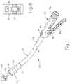
- FIG. 1illustrates a circular anastomosis surgical stapling instrument (50) that includes a distal stapling head assembly (60) connected by a longitudinally curved support shaft assembly (70) to a proximal actuator handle assembly (80).
- Stapling instrument (50)may be constructed in accordance with at least some of the teachings of U.S. Pat. No. 5,205,459 , entitled “Surgical anastomosis stapling instrument,” issued on April 27, 1993; U.S. Pat. No. 5,271,544 , entitled "Surgical anastomosis stapling instrument,” issued on December 21, 1993; U.S. Pat. No.
- Stapling instrument (50)includes an anvil assembly (100) that is slidable longitudinally relative to stapling head assembly (60).
- a rotatable adjusting knob (82)is provided at the proximal end of actuator handle assembly (80) operable to adjust the spacing between stapling head assembly (60) and anvil assembly (100).
- Adjusting knob (82)is in communication with control rod (300) (shown, for example, in FIG. 5 ) such that rotation of adjusting knob (82) causes control rod (300) to translate.
- adjusting knob (82)When adjusting knob (82) is rotated in one direction, the gap between stapling head assembly (60) and anvil assembly (100) closes, whereas when adjusting knob (82) is rotated in a different direction, the gap between stapling head assembly (60) and anvil assembly (100) opens.
- adjusting knob (82)may be operable to open the gap between stapling head assembly (60) and anvil assembly (100) in more than one manner.
- adjusting knob (82)may be moveable in two positions once an operation is complete. In the first position, adjusting knob (82) may create a small gap, whereas in a second position, adjusting knob (82) may create a larger gap. Adjusting knob (82) may be moved to the first position, for example, when stapling instrument (50) is removed from a surgical site; and adjusting knob (82) may be moved to the second position, for example, to remove anvil assembly (100) from stapling head assembly (60). In some versions, the above described gap adjustment mechanism may be controllable through adjusting knob (82).
- a separate actuatormay be integrated into stapling instrument (50) such that when the actuator is used to control the gap between stapling head assembly (60) and anvil assembly (100) after operation, adjusting knob (82) becomes locked out such that the user cannot subsequently operate adjusting knob (82).
- a movable indicator (84)is visible through a window (85) on top of handle assembly (80) to indicate the staple height selected by rotation of adjusting knob (82). As shown in FIG. 5 , indicator (84) is movable along a scale (87) which indicates that the anvil gap is within a desired operating range of stapling instrument (50). The position of indicator (84) also indicates whether the formed staple height will be large or small.
- a staple actuating lever (86)is pivotally mounted on actuator handle assembly (80) for driving the surgical staples from stapling head assembly (60) when anvil assembly (100) is closed to provide the desired staple height.
- a pivotal safety latch (88)is mounted on handle assembly (80) for locking staple actuating lever (86) against movement to preclude actuation of stapling head assembly (60) when the anvil gap is outside of a predetermined range.
- stapling head assembly (60)includes a tubular casing (61) which slidably receives a staple driver (62) which can be advanced and retracted by operation of actuator handle assembly (80).
- Staple driver (62)includes a plurality of fingers (63) for engaging and driving a plurality of staples (90) from a staple holder (68) mounted at the distal end of casing (61).
- Staple holder (68)includes a plurality of staple receiving slots (65) into which staples (90) are inserted.
- Staple driver (62)further supports a circular knife and/or scalpel (69) which is advanced and retracted with staple driver (62).
- Stapling head assembly (60)includes a hollow tubular connector (64) at the proximal end of casing (61) which receives the distal end of support shaft (70).
- a ferrule or sleeve (72)overlaps the joint between tubular connector (64) and the distal end of support shaft (70).
- the proximal end of support shaft (70)is received by a tubular extension (74) at the distal end of actuator handle assembly (80).
- a ferrule or sleeve (76)overlaps the joint between the proximal end of support shaft (70) and the distal end of tubular extension (74).
- anvil assembly (100)includes a generally circular anvil (102) mounted on a hollow axially extending shaft (104) which is detachably secured to a trocar (73) slidably supported by stapling head assembly (60).
- Trocar (73)includes a pointed trocar tip (75) which is inserted into a hollow sleeve (105) at the proximal end of anvil shaft (104). While the illustrated version shows one exemplary orientation for trocar (73) and anvil shaft (104), it will be appreciated that in some versions, the position of trocar (73) and anvil shaft (104) may be reversed such that trocar (73) is positioned on anvil assembly (100) and pointed towards stapling head assembly (60).
- Trocar (73)is slidably received within a central support tube (66) (shown in FIG. 2 ) formed on tubular casing (61) for longitudinal movement relative to staple holder (68) mounted at the distal end of casing (61).
- Staple receiving slots (65) in staple holder (68)are arranged in a circular array for receiving surgical staples (90).
- Staple receiving slots (65) of the exemplary versionare arranged in two closely spaced concentric annular rows.
- Anvil (102)includes an annular rim (106) having a plurality of staple forming grooves for forming staples (90) when driven against anvil (102).
- Anvil assembly (100)includes a pair of elongated, spring-like retainer clips (110) extending longitudinally along anvil shaft (104) for engaging trocar tip (75) when trocar (73) is inserted into anvil shaft (104).
- trocar tip (75)has a low force profile.
- trocar tip (75)is tapered at a shallow angle to reduce the force required to bias open retainer clips (110).
- Retainer clips (110)permit anvil assembly (100) to be attached to or detached from trocar (73) by pushing or pulling, respectively, on anvil assembly (100).
- trocar (73)With stapling instrument (50) in its closed position as shown in FIG. 3 , trocar (73) is retracted into central support tube (66) which restricts radial movement of retainer clips (110) so that detents are held in place against trocar tip (75).
- anvil assembly (100)is locked to trocar (73) so that anvil (102) can resist the full firing force of stapling instrument (50) without disengagement of retainer clips (110) from trocar tip (75).
- Raised circumferential section (152)defines a circumferential notch on anvil shaft (104) which is convenient for purse stringing of the tubular tissue.
- the purse stringed tissuecannot easily slip over raised circumferential section (152).
- the purse stringed tissueis confined to the distal region of anvil shaft (104) beyond raised circumferential section (152) and anvil shaft (104) cannot inadvertently slip through the purse stringed tissue.
- support shaft (70)contains a driver actuating member (92) operable to transmit compressive forces and motion from actuator handle assembly (80) to operate staple driver (62) in stapling head assembly (60). Also, support shaft (70) contains a tension member (94) comprising a pair of elongated flexible bands (95, 96) operable to transmit the tension from actuator handle assembly (80) to anvil assembly (100) to resist the compressive forces exerted on anvil assembly (100). Tension bands (95, 96) transmit longitudinal motion from actuator handle assembly (80) to allow anvil assembly (100) to be adjusted in position relative to stapling head assembly (60).
- a driver actuating member (92)operable to transmit compressive forces and motion from actuator handle assembly (80) to operate staple driver (62) in stapling head assembly (60).
- support shaft (70)contains a tension member (94) comprising a pair of elongated flexible bands (95, 96) operable to transmit the tension from actuator handle assembly (80) to anvil assembly (100) to
- tension member (94)is coupled with control rod (300) such that tension member (94) and control rod (300) translate unitarily.
- An elongated flexible spacer bandis contained within the space between support shaft (70) and flexible tension bands (95, 96).
- control rod (300)By rotating adjusting knob (82) in the opposite direction, i.e., clockwise, control rod (300) is retracted to move tension member (94) in the proximal direction to close the gap between anvil assembly (100) and stapling head assembly (60).
- a stop (309) on cap (89)limits the proximal movement of control rod (300).
- Stapling instrument (50)further comprises a safety release bracket (312), which is translated based on movement of control rod (300).
- a clip (306) that is secured to control rod (300)is configured to engage an upstanding flange (318) of safety release bracket (312) when control rod (300) reaches a certain proximal position. Thereafter, continued proximal movement of control rod (300) will move safety release bracket (312) proximally.
- a coil spring (320)is positioned between flange (318) and a rib (315) of handle assembly (80), and thereby provides a distal bias to safety release bracket (312).
- Safety release bracket (312)is operable to control the movement of indicator (84).
- safety release bracket (312)is operable to communicate movement to an indicator lever (326) via a transversely oriented finger of safety release bracket (312), based on the longitudinal position of control rod (300).
- Indicator (84)is integrally formed at a free end of indicator lever (326).
- FIGS. 2 and 5stapling instrument (50) is shown with anvil assembly (100) fully open and actuator handle assembly (80) in an unfired and unlocked configuration.
- safety release bracket (312)is biased distally by coil spring (320) to urge upstanding flange (318) against rib (315) with the transverse finger of safety release bracket (312) advanced distally and disengaged from indicator lever (326).
- control rod (300)is retracted, as shown in FIG. 6 , clip (306) on control rod (300) is moved in a proximal direction to engage flange (318) and move safety release bracket (312) in the proximal direction.
- the transverse finger of safety release bracket (312)remains disengaged from indicator lever (326).
- the fingerengages and pivots indicator lever (326) to move indicator (84) proximally along scale (87) on window (85) to provide an indication of the selected staple height to be produced when the stapling instrument is fired.
- Safety release bracket (312)is also operable to selectively prevent movement of safety latch (88).
- a portion of safety release bracket (312)physically obstructs pivotal movement of safety latch (88) when control rod (300) is outside of a predetermined longitudinal range; while safety release bracket (312) enables pivotal movement of safety latch (88) when control rod (300) is within the predetermined longitudinal range.
- a longitudinal rangemay correlate with a preferred range of formed staple heights at anvil assembly (100).
- Safety latch (88)is pivotally mounted beneath safety release bracket (312) by a pivot pin (330) extending between handle sections (81). Safety latch (88) is operable to physically prevent actuating lever (86) from being squeezed. For example, in one position shown in FIG. 5 , safety latch (88) blocks actuation of actuating lever (86). In another position shown in FIG. 6 , safety latch (88) is moved to permit actuation of actuating lever (86). Safety latch (88) includes a ledge that, in its latched position, is disposed horizontally underneath safety release bracket (312). If the anvil gap is outside the predetermined range of the stapling instrument (shown in FIGS.
- safety release bracket (312)overlaps ledge on safety latch (88) and prevents safety latch (88) from being disengaged from staple actuating lever (86).
- scale (87)the user can see movable indicator (84) falling outside the zone indicated by scale (87).
- safety release bracket (312)is retracted and ledge on safety latch (88) is disengaged from rectangular plate (314) of safety release bracket (312).
- Safety latch (88)can be pivoted to its unlatched position to enable staple actuating lever (86) to be operated. It will be appreciated that as movable indicator (84) moves into the zone shown by scale (87), movable indicator (84) may be utilized as a visual signal to the user that stapling instrument (50) may be fired.
- safety latch (88)is pivoted clockwise to disengage staple actuating lever (86).
- Stapling instrument (50)is fired by grasping and pivoting staple actuating lever (86) clockwise to move staple actuating lever (86) to its operative position.
- actuator fingers (350) on trigger arm (340)drive firing clip (352) in the distal direction to advance driver actuating member (92) longitudinally along shaft assembly (70).
- Driver actuating member (92)advances staple driver (62) to move driver fingers (63) distally in staple receiving slots (65) to engage staples (90).
- Driver actuating member (92)transmits the required motion and compressive forces from trigger arm (340) to staple driver (62) to drive staples (90) from staple holder (68) into tissue and against anvil (102).
- Each staple (90)is formed into a B-shaped configuration to staple tissue sections (52, 54) together.
- circular knife (69)is advanced by staple driver (62) to cut the tissue against backup washer (160). As shown in FIG. 4 , circular knife (69) splits backup washer (160) into two annular sections.
- staple actuating lever (86)is biased by a spring back to its open, unactuated position shown in FIG. 5 .
- Actuator fingers (350) of trigger arm (340)pivot counterclockwise, as viewed in FIG. 6 , to move firing clip (352) and driver actuating member (92) in the proximal direction.
- staple driver (62)which is connected by locator fingers to driver actuating member (92), and circular knife (69) are retracted into stapling head assembly (60).
- Stapled tissue between anvil (102) and staple holder (68)is released by rotating adjusting knob (82) counterclockwise to advance anvil assembly (100) away from stapling head assembly (60) e.g., by approximately 1/2 of a turn or 3/4 of a turn, etc.
- Anvil (102)is moved through the lumen by manipulating the stapled tissue in a suitable manner to slip the anvil through the stapled lumen. Then, stapling instrument (50) is withdrawn from the patient leaving behind the stapled lumen between tubular tissue sections (52, 54).
- Surgical stapling instrument (50)can be used to perform an intraluminal anastomosis in which two sections of tissue are attached together by an array of staples.
- stapling instrument (50)may be used in a procedure for joining a pair of hollow organ sections (e.g., in a patient's colon or other section of gastro-intestinal tract) end to end with a plurality of surgical staples arranged in a circular array around a hollow lumen between the organ sections.
- purse string suturesare placed in the hollow organs to be anastomosed.
- two tubular tissue sections (52) and (54)are prepared by threading purse string sutures (56) and (58), respectively, into the tissue in purse string fashion adjacent to the open ends of tubular tissue sections (52) and (54).
- stapling instrument (50)is inserted into first tubular tissue section (52), e.g., by insertion into the anal opening of the patient, with anvil assembly (100) attached to stapling head assembly (60) and completely closed.
- adjusting knob (82)is rotated clockwise to retract trocar (73) into support tube (66) and to clamp anvil (102) against staple holder (68).
- Stapling head assembly (60)is positioned adjacent to purse stringed end of tubular tissue section (52).
- adjusting knob (82)is rotated clockwise to advance control rod (300) and tension member (94) until trocar (73) is fully advanced to move anvil assembly (100) to its fully open position ( FIG. 2 ).
- the purse stringed end of tubular tissue section (52)is drawn together about cylindrical trocar body (130) by pulling and tightening purse string suture (56).
- the purse stringed tissueis drawn against cylindrical trocar body (130) and purse string suture (56) is tied to hold the tissue against trocar body (130).
- Anvil assembly (100)is inserted into the purse stringed end of the tubular tissue section (54) and the tissue is drawn together about anvil shaft (104) by pulling and tightening purse string suture (58).
- the purse stringed tissueis pulled against anvil shaft (104) in tying notch (158) distally adjacent to raised circumferential section (152) on anvil shaft (104) and purse stringed suture (58) is tied together.
- anvil assembly (100)may be detached from trocar (73) to facilitate the insertion of anvil assembly (100) into tubular tissue section (54).
- purse string suture (58)After the purse stringed end of tubular tissue section (54) is tied against anvil shaft (104) by purse string suture (58), anvil assembly (100) is re-attached to trocar (73).
- adjusting knob (82)is rotated clockwise to retract trocar (73) into support tube (66) to move anvil (102) toward staple holder (68).
- trocar body (130)slides through the purse stringed end of tissue section (52) in the proximal direction to pull anvil shaft (104) through the purse stringed tissue into support tube (66).
- Stapling instrument (50)eventually reaches the configuration shown in FIG. 3 .
- Actuator handle assembly (80)remains in the fully advanced or open configuration shown in FIG. 5 during this transition.
- safety latch (88, 488, 588, 688)is pivoted upward ( FIGS. 6 , 9 , 11 , 13 , 19 , 22 and 24) to disengage staple actuating lever (86).
- safety latch (88, 488, 588, 688)engages either control rod (300, 400) or adjusting knob (82, 682, 782, 882) to prevent rotation of adjusting knob (82, 682, 782, 882) and to thereby maintain the selected staple height.
- Stapling instrument (50)is fired by grasping and pivoting staple actuating lever (86) clockwise, as viewed in FIG. 7 , to move staple actuating lever (86) to its fired position.
- actuator fingers (350) on trigger arm (340)drive firing clip (352) in the distal direction to advance driver actuating member (92) longitudinally along shaft assembly (70).
- Driver actuating member (92)advances staple driver (62) to move driver fingers (63) distally in staple receiving slots (65) to engage staples (90).
- Driver actuating member (92)transmits the required motion and compressive forces from trigger arm (340) to staple driver (62) to drive staples (90) from staple holder (68) into the tissue and against anvil (102).
- circular knife (69)is advanced by staple driver (62) to cut the tissue against backup washer (160). As shown in FIG. 4 , circular knife (69) splits backup washer (160) into two annular sections. Staples (90) join the ends of tissue sections (52) and (54) with a fluid tight seal formed by concentric annular rows of staples (90). Circular knife (69) cuts away excess tissue within the anastomosis near the stapled region. The severed excess tissue may be trapped within stapling head assembly (60) (e.g., between the interior of circular knife and the exterior of the assembly of trocar (73) and anvil shaft (104)).
- stapling head assembly60
- staple actuating lever (86)is biased by spring (346) to its fully open position ( FIG. 6 ).
- Actuator fingers (350) of trigger arm (340)pivot counterclockwise, as viewed in FIG. 6 , to move firing clip (352) and driver actuating member (92) in the proximal direction.
- staple driver (62)which is connected by locator fingers (230) to driver actuating member (92), and circular knife (69) are retracted into stapling head assembly (60).
- staple driver (62)In case of entrapment of staples, tissue or other debris between staple holder (68) and driver fingers (63), the retraction of staple driver (62) frees stapling head assembly (60) from the tissue before stapling instrument (50) is withdrawn from the patient. If a high force is required, staple actuating lever (86) can be returned manually to its fully advanced position to retract staple driver (62).
- safety latch (88, 488, 588, 688)is pivoted downward to lock staple actuating lever (86) and release adjusting knob (82, 682, 782, 882) so that adjusting knob (82, 682, 782, 882) may freely rotate.
- the stapled tissue between anvil (102) and staple holder (68)is released by rotating adjusting knob (82) counterclockwise to advance anvil assembly (100) away from stapling head assembly (60).
- Anvil (102)is moved through the lumen by manipulating the stapled tissue in a suitable manner to slip the anvil through the stapled lumen.
- stapling instrument (50)is withdrawn from the patient leaving behind the stapled lumen between tubular tissue sections (52) and (54).
- inadvertent firingsare generally undesirable and may be caused for a variety of reasons.
- inadvertent firingsmay be caused simply through unintentional contact with actuating lever (86) after safety latch (88) has been flipped up ( FIG. 6 ).
- inadvertent or incomplete firingsmay be caused by firing stapling instrument (50) when anvil assembly (100) is not properly placed on anvil shaft (104).
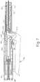
- FIG. 9shows an exemplary stapling instrument (450) comprising an anvil assembly (410) mounted on a shaft (404).
- Stapling instrument (450) of FIG. 9operates substantially similar to stapling instrument (50) described above.
- Stapling instrument (450)comprises an actuator safety switch (451).
- Actuator safety switch (451) in the present exampleis positioned on tubular extension (474).
- actuator safety switch (451)is positioned on tubular extension (474) such that a user is unlikely to inadvertently trigger actuator safety switch (451) as the user holds actuator handle assembly (480) to position stapling instrument (450) for stapling.
- actuator safety switch (451)shows a side view of actuator safety switch (451) as actuator safety switch (451) is in communication with driver actuating member (492) within tubular extension (474).
- Actuator safety switch (451)comprises two opposingly oriented buttons and/or actuators that may be pressed by squeezing the buttons and/or switches toward each other.
- Actuator safety switch (451)is in communication with brake pads (453), which squeeze driver actuating member (492).
- brake pads (453)provides friction that substantially prevents driver actuating member (492) from translating longitudinally, such that brake pads (453) substantially prevent motion and compressive forces to staple driver (62).
- actuator safety switch (451)is connected to brake pads (453) through a scissoring mechanism such that the user may actuate brake pads (453) by squeezing actuator safety switch (451).
- brake pads (453)are resiliently biased to grip driver actuating member (492).
- driver actuating member (492)When a user squeezes actuator safety switch (451), brake pads (453) release driver actuating member (492).
- brake pads (453)selectively grip driver actuating member (492) in the present example, it will be appreciated that brake pads (453) may grip any suitable component of stapling instrument (450) in order to prevent firing of stapling instrument (450) until the user manually releases brake pads (453).
- brake pads (453)prevent the movement of driver actuating member (492) through a frictional grip.
- brake pads (453)may prevent movement of driver actuating member (492) by mechanically coupling with driver actuating member (492).
- brake pads (453)may have pawls operable to engage teeth on driver actuating member (492) such that when engaged, brake pads (453) prevent movement of driver actuating member (492).
- brake pads (453)may be equipped with teeth where driver actuating member (492) is equipped with pawls.
- Other suitable variationswill be apparent to one of ordinary skill in the art in view of the teachings herein.
- actuator safety switch (451)acts in isolation from other components of stapling instrument (450) such that the user can simply operate actuator safety switch (451) to enable driver actuating member (492) to translate staple driver (62).
- actuator safety switch (451)is in communication with safety latch (488) through, for example, a communication rod or linkage, electrical communication, etc. or any other suitable communication mechanism such that actuator safety switch (451) is not operable to release brake pads (453) until safety latch (488) is released.
- safety latch (488)must first be actuated before actuator safety switch (451) may be squeezed to release brake pads (453).
- FIG. 11shows safety latch (488) engaged such that actuating lever (486) cannot be actuated.
- actuator safety switch (451)cannot release brake pads (453) to release driver actuating member (492) until safety latch (488) is released.
- FIGS. 19A-19Cshow a merely illustrative variation where a mechanical linkage (855) is coupled with safety latch (888), such that mechanical linkage (855) moves longitudinally in response to pivoting of safety latch (888).
- safety latch (888)is positioned to prevent actuation of a staple actuating lever (such as staple actuating lever (86) described above, etc.)
- mechanical linkage (855)is positioned to block outward movement of brake pads (853) as shown in FIGS. 19A-19B .
- Mechanical linkage (855)thus keeps brake pads (853) in engagement with driver actuating member (892), thereby preventing driver actuating member (892) from driving staples into tissue, when in the position shown in FIGS. 19A-19B .
- actuator safety switch (451)may be coupled to safety latch (488) such that actuator safety switch (451) engages brake pads (453) to grip driver actuating member (492) only after safety latch (488) is disengaged.
- safety latch (488)operates to prevent firing of stapling instrument (450) until safety latch (488) is disengaged.
- Brake pads (453)are disengaged from driver actuating member (492) while safety latch (488) engages actuating lever (486).
- brake pads (453)engage driver actuating member (492) to prevent stapling instrument (450) from firing.
- brake pads (453)may disengage driver actuating member (492) by the user operating a manual release, by re-engaging safety latch (488) and/or safety switch (451).
- safety switch (451)may be inoperable until movable indicator (84) moves into the zone shown by scale (87).
- safety switch (451)may be inoperable until anvil assembly (410) is fully seated on shaft (404) or a trocar, such as one shown in FIG. 2 .
- safety switch (451)Once safety switch (451) has been enabled and is preventing movement of driver actuating member (492), the user may press actuator safety switch (451) to release brake pads (453) from driver actuating member (492), thereby allowing stapling instrument (450) to fire.
- actuator safety switch (451)may comprise two separately operable buttons and/or switches where one button/switch is operable to cause brake pads (453) to grip and prevent movement of driver actuating member (492), and where the other button/switch is operable to cause brake pads (453) to release driver actuating member (492).
- actuator safety switch (451)may comprise a single switch operable to be switched between two or more positions, where each position of actuator safety switch (451) corresponds to a different action for brake pads (453). For example, one position of actuator safety switch (451) causes brake pads (453) to grip driver actuating member (492), whereas another position of actuator safety switch (451) causes brake pads (453) to release driver actuating member (492).
- Other suitable components, features, configurations, and operabilities that may be included in safety switch (451)will be apparent to one of ordinary skill in the art in view of the teachings herein.
- FIGS. 12-14show an exemplary version of stapling instrument (550) where safety latch (588) comprises a safety feature in the form of a peg (551) that is operable to prevent inadvertent releasing of safety latch (588).
- Peg (551)is movable between a blocked position and an unblocked position. In the blocked position as shown in FIG. 13 , peg (551) prevents safety latch (588) from being moved, such that safety latch continues to prevent the user from being able to move staple actuating lever (586).
- peg (551)In the unblocked position, as shown in FIG. 14 , peg (551) enables the safety latch (588) to be moved, to thereby enable movement of staple actuating lever (586).
- the userfirst moves peg (551) from the blocked position to the unblocked position, thereby allowing safety latch (588) to be released and stapling instrument (550) to be fired.
- Peg (551) of this examplehas a cylindrical shape, though it should be understood that any other suitable shape or configuration may be used.
- pin (551)may be substituted or supplemented with a latch, a sliding lock, etc. or any other suitable mechanism operable to selectively prevent safety latch (588) from moving.
- FIG. 15shows an exemplary version of a stapling instrument (650) having a feature that is operable to verify that anvil assembly (100) is positioned properly on anvil shaft (104) before allowing stapling instrument (650) to fire.
- Stapling instrument (650)is understood to be substantially similar to stapling instrument (550) shown in FIG. 12 , though stapling instrument (650) of this example further comprises an anvil rod (651).
- Anvil rod (651)extends longitudinally through stapling instrument (650) and is in communication with anvil assembly (100).
- FIG. 15shows driver actuating member (92) and control rod (300) in schematic form, just for clarity.
- Driver actuating member (92) and control rod (300) of this examplemay be configured and operable just like the same components described above.
- Anvil rod (651)may be positioned alongside driver actuating member (92) and control rod (300) and may freely translate within shaft (70).
- FIGS. 17A-17Bshow a pivoting safety latch (688) with anvil rod (651) extending through safety latch (688).
- Safety latch (688)includes a safety opening (655) that is shaped and sized to fit a pin (657) inserted into safety opening (655).
- pin (657) of this examplehas a dumbbell shape with a first lobe (670) and second lobe (672) connected by a middle portion (674). It should be understood, however, that pin (657) may have any other suitable shape may be used as would be apparent to one of ordinary skill in the art in view of the teachings herein. For example, an elongate rod having a smaller middle and larger ends may be used for pin (657).
- pin (657)is sized to fit completely through safety opening (655), such that pin (657) may pass entirely through safety opening (655) in either direction.
- pin (657)prevents safety latch (688) from being actuated, such that actuating lever (686) is locked in place by safety latch (688).
- safety latch (688)may be actuated to allow actuating lever (686) to move, thereby allowing stapling instrument (650) to fire.
- anvil rod (651)defines an opening (653) positioned on a proximal end of anvil rod (651).
- Pin (657)is sized and shaped with fit through safety opening (655).
- Opening (653) of anvil rod (651)has a smaller portion (660) and a larger portion (662).
- Pin (657) and opening (653)are sized such that pin (657) can pass through larger portion (662), but not smaller portion (660).
- anvil assembly (100)may effectively be used to control anvil rod (651) to align either smaller portion (660) or larger portion (662) of opening (653) with pin (657).
- pin (657)is aligned with smaller portion (660).
- safety latch (688)remains engaged so as to prevent the user from operating stapling instrument (650).
- anvil rod (651)moves proximally in relation to pin (657) such that pin (657) aligns with larger portion (662) of opening (653), thereby allowing pin (657) to be removed such that safety latch (688) may be actuated.
- proximal movement of anvil rod (651)can only occur if anvil assembly (100) is placed completely on anvil shaft (104).
- safety latch (688)can only be actuated when anvil assembly (100) is properly placed on anvil shaft (104).
- opening (653)is shown as having a generally dumbbell-type shape; however, any suitable shape for opening may be used as would be apparent to one of ordinary skill in the art in view of the teachings herein.
- stapling instrument50, 450, 550, 650
- anvil assembly (100)may be distally moved such that stapling instrument (50, 450, 550, 650) can be removed from the surgical site.
- stapling instrument (50, 450, 550, 650)it may be desirable to avoid firing stapling instrument (50, 450, 550, 650) again.
- stapling instrument (50, 450, 550, 650)uses adjusting knob (82), as shown, for example, in FIG.
- anvil rod (751)may be coupled to adjusting knob (82) such that if adjusting knob (82) is rotated a predetermined amount after stapling instrument (50, 450, 550, 650) completes a firing cycle, anvil rod (751) may be move distally such that safety latch (688) re-engages actuating lever (686) to lock-out actuating lever (686) from firing.
- adjusting knob (82)may be mechanically coupled to any suitable safety related component such that when the user turns adjustment knob (82) in a particular direction after the surgical procedure, stapling instrument (50, 450, 550, 650) is prevented from firing again.
- safety latch (88, 488, 588, 688)may be spring-biased such that safety latch (88, 488, 588, 688) springs back into place after a successful firing of stapling instrument, thereby preventing the user from inadvertently operating actuating lever (86, 486, 586, 686) more than once.
- the usermay subsequently disengage safety latch (88, 488, 588, 688) such that actuating lever (86, 486, 586, 686) can be operated again, but such functionality is not required and in some cases may not be desirable.
- Embodiments of the present inventionhave application in conventional endoscopic and open surgical instrumentation as well as application in robotic-assisted surgery.
- Embodiments of the devices disclosed hereincan be designed to be disposed of after a single use, or they can be designed to be used multiple times. Embodiments may, in either or both cases, be reconditioned for reuse after at least one use. Reconditioning may include any combination of the steps of disassembly of the device, followed by cleaning or replacement of particular pieces, and subsequent reassembly. In particular, embodiments of the device may be disassembled, and any number of the particular pieces or parts of the device may be selectively replaced or removed in any combination. Upon cleaning and/or replacement of particular parts, embodiments of the device may be reassembled for subsequent use either at a reconditioning facility, or by a surgical team immediately prior to a surgical procedure.
- reconditioning of a devicemay utilize a variety of techniques for disassembly, cleaning/replacement, and reassembly. Use of such techniques, and the resulting reconditioned device, are all within the scope of the present application.
- a new or used instrumentmay be obtained and if necessary cleaned.
- the instrumentmay then be sterilized.
- the instrumentis placed in a closed and sealed container, such as a plastic or TYVEK bag.
- the container and instrumentmay then be placed in a field of radiation that can penetrate the container, such as gamma radiation, x-rays, or high-energy electrons.
- the radiationmay kill bacteria on the instrument and in the container.
- the sterilized instrumentmay then be stored in the sterile container.
- the sealed containermay keep the instrument sterile until it is opened in a medical facility.
- a devicemay also be sterilized using any other technique known in the art, including but not limited to beta or gamma radiation, ethylene oxide, or steam.
Landscapes
- Health & Medical Sciences (AREA)
- Life Sciences & Earth Sciences (AREA)
- Surgery (AREA)
- Heart & Thoracic Surgery (AREA)
- Engineering & Computer Science (AREA)
- Biomedical Technology (AREA)
- Nuclear Medicine, Radiotherapy & Molecular Imaging (AREA)
- Medical Informatics (AREA)
- Molecular Biology (AREA)
- Animal Behavior & Ethology (AREA)
- General Health & Medical Sciences (AREA)
- Public Health (AREA)
- Veterinary Medicine (AREA)
- Surgical Instruments (AREA)
Description
- Generally, in the performance of a surgical anastomotic stapling operation, two pieces of lumen or tubular tissue, e.g., intestinal tissue, are attached together by a ring of staples. The two pieces of tubular tissue may be attached end to end or one piece of tubular tissue may be attached laterally around an opening formed in the side of another piece of tubular tissue. In performing the anastomosis with a stapling instrument, the two pieces of tubular tissue are clamped together between an anvil provided with a circular array of staple forming grooves and a staple holder provided with a plurality of staple receiving slots arranged in a circular array in which the staples are received. A staple pusher is advanced to drive the staples into the tissue and form the staples against the anvil. Also, a circular knife is advanced to cut the excess tissue clamped between the anvil and the staple holder. As a result, a donut-shaped section of tissue is severed from each lumen and remains on the anvil shaft. The tubular tissue joined by the circular ring of staples is unclamped by advancing the anvil shaft distally to move the anvil away from the staple holder. The stapling instrument is removed by pulling the anvil through the circular opening between the pieces of tubular tissue attached by the ring of staples.
- Examples of such circular surgical staplers are described in
U.S. Pat. No. 5,205,459 , entitled "Surgical Anastomosis Stapling Instrument," issued April 27, 1993;U.S. Pat. No. 5,271,544 , entitled "Surgical Anastomosis Stapling Instrument," issued December 21, 1993;U.S. Pat. No. 5,275,322 , entitled "Surgical Anastomosis Stapling Instrument," issued January 4, 1994;U.S. Pat. No. 5,285,945 , entitled "Surgical Anastomosis Stapling Instrument," issued February 15, 1994;U.S. Pat. No. 5,292,053 , entitled "Surgical Anastomosis Stapling Instrument," issued March 8, 1994;U.S. Pat. No. 5,333,773 , entitled "Surgical Anastomosis Stapling Instrument," issued August 2, 1994;U.S. Pat. No. 5,350,104 , entitled "Surgical Anastomosis Stapling Instrument," issued September 27, 1994; andU.S. Pat. No. 5,533,661 , entitled "Surgical Anastomosis Stapling Instrument," issued July 9, 1996. Some such staplers are operable to clamp down on layers of tissue, cut through the clamped layers of tissue, and drive staples through the layers of tissue to substantially seal the severed layers of tissue together near the severed ends of the tissue layers. - Merely additional other exemplary surgical staplers are disclosed in
U.S. Pat. No. 4,805,823 , entitled "Pocket Configuration for Internal Organ Staplers," issued February 21, 1989;U.S. Pat. No. 5,415,334 , entitled "Surgical Stapler and Staple Cartridge," issued May 16, 1995;U.S. Pat. No. 5,465,895 , entitled "Surgical Stapler Instrument," issued November 14, 1995;U.S. Pat. No. 5,597,107 , entitled "Surgical Stapler Instrument," issued January 28, 1997;U.S. Pat. No. 5,632,432 , entitled "Surgical Instrument," issued May 27, 1997;U.S. Pat. No. 5,673,840 , entitled "Surgical Instrument," issued October 7, 1997;U.S. Pat. No. 5,704,534 , entitled "Articulation Assembly for Surgical Instruments," issued January 6, 1998;U.S. Pat. No. 5,814,055 , entitled "Surgical Clamping Mechanism," issued September 29, 1998;U.S. Pat. No. 6,978,921 , entitled "Surgical Stapling Instrument Incorporating an E-Beam Firing Mechanism," issued December 27, 2005;U.S. Pat. No. 7,000,818 , entitled "Surgical Stapling Instrument Having Separate Distinct Closing and Firing Systems," issued February 21, 2006;U.S. Pat. No. 7,143,923 , entitled "Surgical Stapling Instrument Having a Firing Lockout for an Unclosed Anvil," issued December 5, 2006;U.S. Pat. No. 7,303,108 , entitled "Surgical Stapling Instrument Incorporating a Multi-Stroke Firing Mechanism with a Flexible Rack," issued December 4, 2007;U.S. Pat. No. 7,367,485 , entitled "Surgical Stapling Instrument Incorporating a Multistroke Firing Mechanism Having a Rotary Transmission," issued May 6, 2008;U.S. Pat. No. 7,380,695 , entitled "Surgical Stapling Instrument Having a Single Lockout Mechanism for Prevention of Firing," issued June 3, 2008;U.S. Pat. No. 7,380,696 , entitled "Articulating Surgical Stapling Instrument Incorporating a Two-Piece E-Beam Firing Mechanism," issued June 3, 2008;U.S. Pat. No. 7,404,508 , entitled "Surgical Stapling and Cutting Device," issued July 29, 2008;U.S. Pat. No. 7,434,715 , entitled "Surgical Stapling Instrument Having Multistroke Firing with Opening Lockout," issued October 14, 2008; andU.S. Pat. No. 7,721,930 , entitled "Disposable Cartridge with Adhesive for Use with a Stapling Device," issued May 25, 2010. While the surgical staplers referred to above are described as being used in endoscopic procedures, it should be understood that such surgical staplers may also be used in open procedures and/or other non-endoscopic procedures. U.S. Patent No. 5,685,474 describes a surgical instrument for applying a circular array of fasteners. The instrument includes an elongate body portion and a handle section. The handle section includes an anvil adjustment member, a lever lockout or safety member and fastener firing levers. A fastener head portion and an anvil member are disposed at the distal end of the body portion. Also disposed on the instrument are two lockout devices, a first lockout member formed to lockout the firing levers and a second lockout member formed to lockout movement of an elongated member that controls approximation of the anvil and fastener firing member. The first lockout member is preferably spring biased to the locked out position by a spring. Each of these lockout members is preferably mounted on the instrument in such a way that they are fixed relative to each other and upon pivoting of the first lockout member, the second lockout member also pivots. Once the user has the instrument inserted and the tissue to be joined is properly situated about the distal end of the instrument, the anvil is approximated to its proper position by rotation of the anvil adjustment member, and the instrument is positioned for firing. In that position, however, the fastener firing member remains blocked from movement due to the first lockout member being oriented in the "safety on" position, in which lever locking extended portions are aligned with the structure of the firing levers so that they cannot be depressed. Pivoting of the first lockout member is prevented when the elongated member is out of the desired approximation range for firing the staples.- While a variety of surgical staplers have been made and used, it is believed that no one prior to the inventor(s) has made or used an invention as described herein.
- According to the invention a surgical stapler is provided, the surgical stapler comprising: (a) an end operable to drive a plurality of staples into tissue, wherein the end effector comprises an anvil assembly that is slidable longitudinally relative to a stapling head assembly to define an anvil gap between them; (b) a staple driver operable to actuate the end effector to drive the plurality of staples into tissue; (c) a trigger operable to actuate the staple driver to thereby actuate the end effector; (d) a safety latch moveable between a locked position and an unlocked position, wherein the safety latch is operable to prevent operation of the trigger when the safety latch is in the locked position, wherein the safety latch is operable to enable operation of the trigger when the safety latch is in the unlocked position, wherein the safety latch is prevented from moving to the unlocked position when the anvil gap is outside a predetermined operating range; and (e) a safety feature configured to prevent operation of the staple driver when the safety latch is in the unlocked position; wherein the safety feature comprises an actuating switch and a braking assembly, the staple driver is actuated by movement of a translating driver actuating member, and the actuating switch is operable to control the braking assembly such that the braking assembly is operable to selectively grip or release the driver actuating member.
- Further, the actuating switch may comprise at least one button, wherein the at least one button is operable to be actuated between at least two positions, wherein the at least one button is configured to direct brake pads to grip the driver actuating member, wherein the at least one button is further configured to direct brake pads to release the driver actuating member.
- While the specification concludes with claims which particularly point out and distinctly claim the invention, it is believed the present invention will be better understood from the following description of certain examples taken in conjunction with the accompanying drawings, in which like reference numerals identify the same elements and in which:
FIG. 1 depicts a perspective view of an exemplary stapler instrument;FIG. 2 depicts a side, cross sectional view of a stapling head assembly of the stapler instrument ofFIG. 1 ;FIG. 3 depicts a side, cross sectional view of the stapling head assembly ofFIG. 2 in a closed position;FIG. 4 depicts a side, cross sectional view of the stapling head assembly ofFIG. 2 showing a staple driver in a fired position;FIG. 5 depicts a side, cross sectional view of the stapler instrument ofFIG. 1 showing the actuator handle assembly in a locked position;FIG. 6 depicts a side, cross sectional view of the actuator handle assembly ofFIG. 5 in an unlocked position;FIG. 7 depicts a side, cross sectional view of the actuator handle assembly ofFIG. 5 in a fired position;FIG. 8 depicts a front view of an indictor window on top of the actuator handle assembly ofFIG. 5 ;FIG. 9 depicts a perspective view of an exemplary stapler instrument with a safety feature;FIG. 10 depicts a side view of a brake and driver actuating member inside the stapler instrument ofFIG. 9 ;FIG. 11 depicts a side, cross sectional view of the stapler instrument ofFIG. 9 ;FIG. 12 depicts a side cross sectional view of another exemplary stapler instrument having a safety feature;FIG. 13 depicts a perspective view of the safety feature ofFIG. 12 in a locked position;FIG. 14 depicts a perspective view of the safety feature ofFIG. 12 in an unlocked position;FIG. 15 depicts a side, cross sectional view of an exemplary stapler instrument having an alternative safety feature;FIG. 16 depicts a front, elevational view of a pin for use with the safety feature ofFIG. 15 ;FIG. 17A depicts a side view of the safety feature ofFIG. 15 with an anvil rod in a distal position;FIG. 17B depicts a side view of the safety feature ofFIG. 15 with the anvil rod in a proximal position;FIG. 18 depicts a side view of an exemplary anvil rod for use with the stapler instrument ofFIG. 15 ;FIG. 19A depicts a side view of a brake and driver actuating member inside the stapler instrument, with a mechanical linkage in a first position to restrict movement of the brake and driver actuating member;FIG. 19B depicts a top view of a brake, driver actuating member, and mechanical linkage ofFIG. 19A inside the stapler instrument, with the mechanical linkage in the first position; andFIG. 19C depicts a top view of a brake, driver actuating member, and mechanical linkage ofFIG. 19A inside the stapler instrument, with the mechanical linkage moved to a second position to enable outward movement of the brake and driver actuating member.- The drawings are not intended to be limiting in any way, and it is contemplated that various embodiments of the invention may be carried out in a variety of other ways, including those not necessarily depicted in the drawings. The accompanying drawings incorporated in and forming a part of the specification illustrate several aspects of the present invention, and together with the description serve to explain the principles of the invention; it being understood, however, that this invention is not limited to the precise arrangements shown.
- The following description of certain examples of the invention should not be used to limit the scope of the present invention. Other examples, features, aspects, embodiments, and advantages of the invention will become apparent to those skilled in the art from the following description, which is by way of illustration, one of the best modes contemplated for carrying out the invention. As will be realized, the invention is capable of other different and obvious aspects, all without departing from the invention. Accordingly, the drawings and descriptions should be regarded as illustrative in nature and not restrictive.
FIG. 1 illustrates a circular anastomosis surgical stapling instrument (50) that includes a distal stapling head assembly (60) connected by a longitudinally curved support shaft assembly (70) to a proximal actuator handle assembly (80). Stapling instrument (50) may be constructed in accordance with at least some of the teachings ofU.S. Pat. No. 5,205,459 , entitled "Surgical anastomosis stapling instrument," issued on April 27, 1993;U.S. Pat. No. 5,271,544 , entitled "Surgical anastomosis stapling instrument," issued on December 21, 1993;U.S. Pat. No. 5,275,322 , entitled "Surgical anastomosis stapling instrument," issued on January 4, 1994;U.S. Pat. No. 5,285,945 , entitled "Surgical anastomosis stapling instrument," issued on February 15, 1994;U.S. Pat. No. 5,292,053 , entitled "Surgical anastomosis stapling instrument," issued on March 10, 1993;U.S. Pat. No. 5,333,773 , entitled "Sealing means for endoscopic surgical anastomosis stapling instrument," issued on April 2, 1994;U.S. Pat. No. 5,350,104 , entitled "Sealing means for endoscopic surgical anastomosis stapling instrument," issued on September 27, 1994; and/orU.S. Pat. No. 5,533,661 entitled "Sealing means for endoscopic surgical anastomosis stapling instrument," issued on July 9, 1996.- Stapling instrument (50) includes an anvil assembly (100) that is slidable longitudinally relative to stapling head assembly (60). A rotatable adjusting knob (82) is provided at the proximal end of actuator handle assembly (80) operable to adjust the spacing between stapling head assembly (60) and anvil assembly (100). Adjusting knob (82) is in communication with control rod (300) (shown, for example, in
FIG. 5 ) such that rotation of adjusting knob (82) causes control rod (300) to translate. When adjusting knob (82) is rotated in one direction, the gap between stapling head assembly (60) and anvil assembly (100) closes, whereas when adjusting knob (82) is rotated in a different direction, the gap between stapling head assembly (60) and anvil assembly (100) opens. While the exemplary version comprises adjusting knob (82), it will be appreciated that a button, actuator, or any other suitable mechanism may be used in place of adjusting knob (82) as would be apparent to one of ordinary skill in the art in view of the teachings herein. In some versions, adjusting knob (82) may be operable to open the gap between stapling head assembly (60) and anvil assembly (100) in more than one manner. For example, adjusting knob (82) may be moveable in two positions once an operation is complete. In the first position, adjusting knob (82) may create a small gap, whereas in a second position, adjusting knob (82) may create a larger gap. Adjusting knob (82) may be moved to the first position, for example, when stapling instrument (50) is removed from a surgical site; and adjusting knob (82) may be moved to the second position, for example, to remove anvil assembly (100) from stapling head assembly (60). In some versions, the above described gap adjustment mechanism may be controllable through adjusting knob (82). In some other versions, a separate actuator may be integrated into stapling instrument (50) such that when the actuator is used to control the gap between stapling head assembly (60) and anvil assembly (100) after operation, adjusting knob (82) becomes locked out such that the user cannot subsequently operate adjusting knob (82). - A movable indicator (84) is visible through a window (85) on top of handle assembly (80) to indicate the staple height selected by rotation of adjusting knob (82). As shown in
FIG. 5 , indicator (84) is movable along a scale (87) which indicates that the anvil gap is within a desired operating range of stapling instrument (50). The position of indicator (84) also indicates whether the formed staple height will be large or small. - A staple actuating lever (86) is pivotally mounted on actuator handle assembly (80) for driving the surgical staples from stapling head assembly (60) when anvil assembly (100) is closed to provide the desired staple height. A pivotal safety latch (88) is mounted on handle assembly (80) for locking staple actuating lever (86) against movement to preclude actuation of stapling head assembly (60) when the anvil gap is outside of a predetermined range.
- Referring to
FIG. 2 , stapling head assembly (60) includes a tubular casing (61) which slidably receives a staple driver (62) which can be advanced and retracted by operation of actuator handle assembly (80). Staple driver (62) includes a plurality of fingers (63) for engaging and driving a plurality of staples (90) from a staple holder (68) mounted at the distal end of casing (61). Staple holder (68) includes a plurality of staple receiving slots (65) into which staples (90) are inserted. Staple driver (62) further supports a circular knife and/or scalpel (69) which is advanced and retracted with staple driver (62). - Stapling head assembly (60) includes a hollow tubular connector (64) at the proximal end of casing (61) which receives the distal end of support shaft (70). A ferrule or sleeve (72) overlaps the joint between tubular connector (64) and the distal end of support shaft (70). Similarly, the proximal end of support shaft (70) is received by a tubular extension (74) at the distal end of actuator handle assembly (80). A ferrule or sleeve (76) overlaps the joint between the proximal end of support shaft (70) and the distal end of tubular extension (74).
- Still referring to
FIG. 2 , anvil assembly (100) includes a generally circular anvil (102) mounted on a hollow axially extending shaft (104) which is detachably secured to a trocar (73) slidably supported by stapling head assembly (60). Trocar (73) includes a pointed trocar tip (75) which is inserted into a hollow sleeve (105) at the proximal end of anvil shaft (104). While the illustrated version shows one exemplary orientation for trocar (73) and anvil shaft (104), it will be appreciated that in some versions, the position of trocar (73) and anvil shaft (104) may be reversed such that trocar (73) is positioned on anvil assembly (100) and pointed towards stapling head assembly (60). Other suitable variations may be used as would be apparent to one of ordinary skill the art in view of the teachings herein. Trocar (73) is slidably received within a central support tube (66) (shown inFIG. 2 ) formed on tubular casing (61) for longitudinal movement relative to staple holder (68) mounted at the distal end of casing (61). Staple receiving slots (65) in staple holder (68) are arranged in a circular array for receiving surgical staples (90). Staple receiving slots (65) of the exemplary version are arranged in two closely spaced concentric annular rows. Anvil (102) includes an annular rim (106) having a plurality of staple forming grooves for forming staples (90) when driven against anvil (102). - Anvil assembly (100) includes a pair of elongated, spring-like retainer clips (110) extending longitudinally along anvil shaft (104) for engaging trocar tip (75) when trocar (73) is inserted into anvil shaft (104). To facilitate the insertion of trocar (73) into anvil shaft (104), trocar tip (75) has a low force profile. In the exemplary version, trocar tip (75) is tapered at a shallow angle to reduce the force required to bias open retainer clips (110).
- Retainer clips (110) permit anvil assembly (100) to be attached to or detached from trocar (73) by pushing or pulling, respectively, on anvil assembly (100). With stapling instrument (50) in its closed position as shown in
FIG. 3 , trocar (73) is retracted into central support tube (66) which restricts radial movement of retainer clips (110) so that detents are held in place against trocar tip (75). As a result, anvil assembly (100) is locked to trocar (73) so that anvil (102) can resist the full firing force of stapling instrument (50) without disengagement of retainer clips (110) from trocar tip (75). - Raised circumferential section (152) defines a circumferential notch on anvil shaft (104) which is convenient for purse stringing of the tubular tissue. As shown in
FIG. 2 , if the tissue is tightly purse stringed to shaft (104), the purse stringed tissue cannot easily slip over raised circumferential section (152). As a result, the purse stringed tissue is confined to the distal region of anvil shaft (104) beyond raised circumferential section (152) and anvil shaft (104) cannot inadvertently slip through the purse stringed tissue. - Referring to
FIGS. 4 and5 , support shaft (70) contains a driver actuating member (92) operable to transmit compressive forces and motion from actuator handle assembly (80) to operate staple driver (62) in stapling head assembly (60). Also, support shaft (70) contains a tension member (94) comprising a pair of elongated flexible bands (95, 96) operable to transmit the tension from actuator handle assembly (80) to anvil assembly (100) to resist the compressive forces exerted on anvil assembly (100). Tension bands (95, 96) transmit longitudinal motion from actuator handle assembly (80) to allow anvil assembly (100) to be adjusted in position relative to stapling head assembly (60). In particular, tension member (94) is coupled with control rod (300) such that tension member (94) and control rod (300) translate unitarily. An elongated flexible spacer band is contained within the space between support shaft (70) and flexible tension bands (95, 96). By rotating adjusting knob (82) in the counterclockwise direction, as viewed, for example, inFIG. 1 , control rod (300) is advanced to move tension member (94) in the distal direction to open the gap between anvil assembly (100) and stapling head assembly (60). A stop (307) (shown inFIG. 5 ) on one of handle sections (81) engages screw (308) to limit the distal movement of control rod (300). By rotating adjusting knob (82) in the opposite direction, i.e., clockwise, control rod (300) is retracted to move tension member (94) in the proximal direction to close the gap between anvil assembly (100) and stapling head assembly (60). A stop (309) on cap (89) limits the proximal movement of control rod (300). - Stapling instrument (50) further comprises a safety release bracket (312), which is translated based on movement of control rod (300). In particular, a clip (306) that is secured to control rod (300) is configured to engage an upstanding flange (318) of safety release bracket (312) when control rod (300) reaches a certain proximal position. Thereafter, continued proximal movement of control rod (300) will move safety release bracket (312) proximally. A coil spring (320) is positioned between flange (318) and a rib (315) of handle assembly (80), and thereby provides a distal bias to safety release bracket (312). Thus, when safety release bracket (312) is in a proximal position and control rod (300) is advanced distally, coil spring (320) will move safety release bracket (312) distally. Safety release bracket (312) is operable to control the movement of indicator (84). In particular, safety release bracket (312) is operable to communicate movement to an indicator lever (326) via a transversely oriented finger of safety release bracket (312), based on the longitudinal position of control rod (300). Indicator (84) is integrally formed at a free end of indicator lever (326).
- In
FIGS. 2 and5 , stapling instrument (50) is shown with anvil assembly (100) fully open and actuator handle assembly (80) in an unfired and unlocked configuration. With anvil assembly (100) fully open, safety release bracket (312) is biased distally by coil spring (320) to urge upstanding flange (318) against rib (315) with the transverse finger of safety release bracket (312) advanced distally and disengaged from indicator lever (326). When control rod (300) is retracted, as shown inFIG. 6 , clip (306) on control rod (300) is moved in a proximal direction to engage flange (318) and move safety release bracket (312) in the proximal direction. Initially, as anvil assembly (100) begins to close, the transverse finger of safety release bracket (312) remains disengaged from indicator lever (326). When the gap between anvil assembly (100) and stapling assembly (60) is adjusted into a predetermined range of the instrument, the finger engages and pivots indicator lever (326) to move indicator (84) proximally along scale (87) on window (85) to provide an indication of the selected staple height to be produced when the stapling instrument is fired. - Safety release bracket (312) is also operable to selectively prevent movement of safety latch (88). In particular, as will be described in greater detail below, a portion of safety release bracket (312) physically obstructs pivotal movement of safety latch (88) when control rod (300) is outside of a predetermined longitudinal range; while safety release bracket (312) enables pivotal movement of safety latch (88) when control rod (300) is within the predetermined longitudinal range. Such a longitudinal range may correlate with a preferred range of formed staple heights at anvil assembly (100).
- Safety latch (88) is pivotally mounted beneath safety release bracket (312) by a pivot pin (330) extending between handle sections (81). Safety latch (88) is operable to physically prevent actuating lever (86) from being squeezed. For example, in one position shown in
FIG. 5 , safety latch (88) blocks actuation of actuating lever (86). In another position shown inFIG. 6 , safety latch (88) is moved to permit actuation of actuating lever (86). Safety latch (88) includes a ledge that, in its latched position, is disposed horizontally underneath safety release bracket (312). If the anvil gap is outside the predetermined range of the stapling instrument (shown inFIGS. 2 and5 ), rectangular plate (314) of safety release bracket (312) overlaps ledge on safety latch (88) and prevents safety latch (88) from being disengaged from staple actuating lever (86). On scale (87), the user can see movable indicator (84) falling outside the zone indicated by scale (87). On the other hand, when the anvil gap is within the predetermined range (shown inFIGS. 3 and6 ), safety release bracket (312) is retracted and ledge on safety latch (88) is disengaged from rectangular plate (314) of safety release bracket (312). Safety latch (88) can be pivoted to its unlatched position to enable staple actuating lever (86) to be operated. It will be appreciated that as movable indicator (84) moves into the zone shown by scale (87), movable indicator (84) may be utilized as a visual signal to the user that stapling instrument (50) may be fired. - When the gap between anvil (102) and staple holder (68) is set to produce a desired staple height within the operating range of stapling instrument (50), safety latch (88) is pivoted clockwise to disengage staple actuating lever (86). Stapling instrument (50) is fired by grasping and pivoting staple actuating lever (86) clockwise to move staple actuating lever (86) to its operative position. As a result, actuator fingers (350) on trigger arm (340) drive firing clip (352) in the distal direction to advance driver actuating member (92) longitudinally along shaft assembly (70). Driver actuating member (92) advances staple driver (62) to move driver fingers (63) distally in staple receiving slots (65) to engage staples (90). Driver actuating member (92) transmits the required motion and compressive forces from trigger arm (340) to staple driver (62) to drive staples (90) from staple holder (68) into tissue and against anvil (102). Each staple (90) is formed into a B-shaped configuration to staple tissue sections (52, 54) together. Also, circular knife (69) is advanced by staple driver (62) to cut the tissue against backup washer (160). As shown in
FIG. 4 , circular knife (69) splits backup washer (160) into two annular sections. - After the stapling and cutting of the tissue is completed, staple actuating lever (86) is biased by a spring back to its open, unactuated position shown in
FIG. 5 . Actuator fingers (350) of trigger arm (340) pivot counterclockwise, as viewed inFIG. 6 , to move firing clip (352) and driver actuating member (92) in the proximal direction. As a result, staple driver (62), which is connected by locator fingers to driver actuating member (92), and circular knife (69) are retracted into stapling head assembly (60). - Stapled tissue between anvil (102) and staple holder (68) is released by rotating adjusting knob (82) counterclockwise to advance anvil assembly (100) away from stapling head assembly (60) e.g., by approximately 1/2 of a turn or 3/4 of a turn, etc. Anvil (102) is moved through the lumen by manipulating the stapled tissue in a suitable manner to slip the anvil through the stapled lumen. Then, stapling instrument (50) is withdrawn from the patient leaving behind the stapled lumen between tubular tissue sections (52, 54).
- Surgical stapling instrument (50) can be used to perform an intraluminal anastomosis in which two sections of tissue are attached together by an array of staples. By way of example, stapling instrument (50) may be used in a procedure for joining a pair of hollow organ sections (e.g., in a patient's colon or other section of gastro-intestinal tract) end to end with a plurality of surgical staples arranged in a circular array around a hollow lumen between the organ sections. In preparation for the anastomosis, purse string sutures are placed in the hollow organs to be anastomosed. For example, as shown in
FIG. 2 , two tubular tissue sections (52) and (54) are prepared by threading purse string sutures (56) and (58), respectively, into the tissue in purse string fashion adjacent to the open ends of tubular tissue sections (52) and (54). - If the surgical procedure is performed using a double purse string suturing technique, stapling instrument (50) is inserted into first tubular tissue section (52), e.g., by insertion into the anal opening of the patient, with anvil assembly (100) attached to stapling head assembly (60) and completely closed. Prior to insertion of stapling instrument (50) into the patient, adjusting knob (82) is rotated clockwise to retract trocar (73) into support tube (66) and to clamp anvil (102) against staple holder (68). Stapling head assembly (60) is positioned adjacent to purse stringed end of tubular tissue section (52). Next, adjusting knob (82) is rotated clockwise to advance control rod (300) and tension member (94) until trocar (73) is fully advanced to move anvil assembly (100) to its fully open position (
FIG. 2 ). With trocar (73) fully advanced, the purse stringed end of tubular tissue section (52) is drawn together about cylindrical trocar body (130) by pulling and tightening purse string suture (56). The purse stringed tissue is drawn against cylindrical trocar body (130) and purse string suture (56) is tied to hold the tissue against trocar body (130). - Anvil assembly (100) is inserted into the purse stringed end of the tubular tissue section (54) and the tissue is drawn together about anvil shaft (104) by pulling and tightening purse string suture (58). The purse stringed tissue is pulled against anvil shaft (104) in tying notch (158) distally adjacent to raised circumferential section (152) on anvil shaft (104) and purse stringed suture (58) is tied together. If desired, anvil assembly (100) may be detached from trocar (73) to facilitate the insertion of anvil assembly (100) into tubular tissue section (54). After the purse stringed end of tubular tissue section (54) is tied against anvil shaft (104) by purse string suture (58), anvil assembly (100) is re-attached to trocar (73).
- After the purse stringed ends of tubular tissue sections (52) and (54) are tied, adjusting knob (82) is rotated clockwise to retract trocar (73) into support tube (66) to move anvil (102) toward staple holder (68). As trocar (73) is retracted, trocar body (130) slides through the purse stringed end of tissue section (52) in the proximal direction to pull anvil shaft (104) through the purse stringed tissue into support tube (66). Stapling instrument (50) eventually reaches the configuration shown in
FIG. 3 . Actuator handle assembly (80) remains in the fully advanced or open configuration shown inFIG. 5 during this transition. - When the gap between anvil (102) and staple holder (68) is set to produce a desired staple height within the operating range of stapling instrument (50), safety latch (88, 488, 588, 688) is pivoted upward (
FIGS. 6 ,9 ,11 ,13 ,19 , 22 and 24) to disengage staple actuating lever (86). In the pivoted position, safety latch (88, 488, 588, 688) engages either control rod (300, 400) or adjusting knob (82, 682, 782, 882) to prevent rotation of adjusting knob (82, 682, 782, 882) and to thereby maintain the selected staple height. Stapling instrument (50) is fired by grasping and pivoting staple actuating lever (86) clockwise, as viewed inFIG. 7 , to move staple actuating lever (86) to its fired position. As a result, actuator fingers (350) on trigger arm (340) drive firing clip (352) in the distal direction to advance driver actuating member (92) longitudinally along shaft assembly (70). Driver actuating member (92) advances staple driver (62) to move driver fingers (63) distally in staple receiving slots (65) to engage staples (90). Driver actuating member (92) transmits the required motion and compressive forces from trigger arm (340) to staple driver (62) to drive staples (90) from staple holder (68) into the tissue and against anvil (102). Also, circular knife (69) is advanced by staple driver (62) to cut the tissue against backup washer (160). As shown inFIG. 4 , circular knife (69) splits backup washer (160) into two annular sections. Staples (90) join the ends of tissue sections (52) and (54) with a fluid tight seal formed by concentric annular rows of staples (90). Circular knife (69) cuts away excess tissue within the anastomosis near the stapled region. The severed excess tissue may be trapped within stapling head assembly (60) (e.g., between the interior of circular knife and the exterior of the assembly of trocar (73) and anvil shaft (104)). - After the stapling and cutting of the tissue is completed, staple actuating lever (86) is biased by spring (346) to its fully open position (
FIG. 6 ). Actuator fingers (350) of trigger arm (340) pivot counterclockwise, as viewed inFIG. 6 , to move firing clip (352) and driver actuating member (92) in the proximal direction. As a result, staple driver (62), which is connected by locator fingers (230) to driver actuating member (92), and circular knife (69) are retracted into stapling head assembly (60). In case of entrapment of staples, tissue or other debris between staple holder (68) and driver fingers (63), the retraction of staple driver (62) frees stapling head assembly (60) from the tissue before stapling instrument (50) is withdrawn from the patient. If a high force is required, staple actuating lever (86) can be returned manually to its fully advanced position to retract staple driver (62). - Next, safety latch (88, 488, 588, 688) is pivoted downward to lock staple actuating lever (86) and release adjusting knob (82, 682, 782, 882) so that adjusting knob (82, 682, 782, 882) may freely rotate. The stapled tissue between anvil (102) and staple holder (68) is released by rotating adjusting knob (82) counterclockwise to advance anvil assembly (100) away from stapling head assembly (60). Anvil (102) is moved through the lumen by manipulating the stapled tissue in a suitable manner to slip the anvil through the stapled lumen. Then, stapling instrument (50) is withdrawn from the patient leaving behind the stapled lumen between tubular tissue sections (52) and (54).
- It will be appreciated that inadvertent firings are generally undesirable and may be caused for a variety of reasons. In some instances, inadvertent firings may be caused simply through unintentional contact with actuating lever (86) after safety latch (88) has been flipped up (
FIG. 6 ). Thus, it may be desirable to prevent movement of actuating lever (86), even after movable indicator (84) is positioned in scale (87) and safety latch (88) is flipped up, until the user is ready to insert staples into tissue. In some instances, inadvertent or incomplete firings may be caused by firing stapling instrument (50) when anvil assembly (100) is not properly placed on anvil shaft (104). Thus, in those instances, it may be desirable to prevent the firing of surgical instrument (50) until anvil assembly (100) is properly placed on anvil shaft (104). It will further be appreciated that firings may be generally undesirable if movable indicator (84) is not positioned in scale (87) (i.e., when the anvil gap is outside of the "green zone"). FIG. 9 shows an exemplary stapling instrument (450) comprising an anvil assembly (410) mounted on a shaft (404). Stapling instrument (450) ofFIG. 9 operates substantially similar to stapling instrument (50) described above. Stapling instrument (450) comprises an actuator safety switch (451). Actuator safety switch (451) in the present example is positioned on tubular extension (474). Furthermore, actuator safety switch (451) is positioned on tubular extension (474) such that a user is unlikely to inadvertently trigger actuator safety switch (451) as the user holds actuator handle assembly (480) to position stapling instrument (450) for stapling.FIG. 10 shows a side view of actuator safety switch (451) as actuator safety switch (451) is in communication with driver actuating member (492) within tubular extension (474). Actuator safety switch (451) comprises two opposingly oriented buttons and/or actuators that may be pressed by squeezing the buttons and/or switches toward each other. Actuator safety switch (451) is in communication with brake pads (453), which squeeze driver actuating member (492). Such squeezing by brake pads (453) provides friction that substantially prevents driver actuating member (492) from translating longitudinally, such that brake pads (453) substantially prevent motion and compressive forces to staple driver (62).- In the present example, actuator safety switch (451) is connected to brake pads (453) through a scissoring mechanism such that the user may actuate brake pads (453) by squeezing actuator safety switch (451). In some versions, brake pads (453) are resiliently biased to grip driver actuating member (492). Thus, when a user squeezes actuator safety switch (451), brake pads (453) release driver actuating member (492). While brake pads (453) selectively grip driver actuating member (492) in the present example, it will be appreciated that brake pads (453) may grip any suitable component of stapling instrument (450) in order to prevent firing of stapling instrument (450) until the user manually releases brake pads (453). In some versions, brake pads (453) prevent the movement of driver actuating member (492) through a frictional grip. As another merely illustrative variation, brake pads (453) may prevent movement of driver actuating member (492) by mechanically coupling with driver actuating member (492). For example, brake pads (453) may have pawls operable to engage teeth on driver actuating member (492) such that when engaged, brake pads (453) prevent movement of driver actuating member (492). As yet another merely illustrative variation, brake pads (453) may be equipped with teeth where driver actuating member (492) is equipped with pawls. Other suitable variations will be apparent to one of ordinary skill in the art in view of the teachings herein.
- In some versions, actuator safety switch (451) acts in isolation from other components of stapling instrument (450) such that the user can simply operate actuator safety switch (451) to enable driver actuating member (492) to translate staple driver (62). In some versions, actuator safety switch (451) is in communication with safety latch (488) through, for example, a communication rod or linkage, electrical communication, etc. or any other suitable communication mechanism such that actuator safety switch (451) is not operable to release brake pads (453) until safety latch (488) is released. Thus, during operation in some versions, safety latch (488) must first be actuated before actuator safety switch (451) may be squeezed to release brake pads (453). For example,
FIG. 11 shows safety latch (488) engaged such that actuating lever (486) cannot be actuated. In addition, actuator safety switch (451) cannot release brake pads (453) to release driver actuating member (492) until safety latch (488) is released. FIGS. 19A-19C show a merely illustrative variation where a mechanical linkage (855) is coupled with safety latch (888), such that mechanical linkage (855) moves longitudinally in response to pivoting of safety latch (888). When safety latch (888) is positioned to prevent actuation of a staple actuating lever (such as staple actuating lever (86) described above, etc.), mechanical linkage (855) is positioned to block outward movement of brake pads (853) as shown inFIGS. 19A-19B . Mechanical linkage (855) thus keeps brake pads (853) in engagement with driver actuating member (892), thereby preventing driver actuating member (892) from driving staples into tissue, when in the position shown inFIGS. 19A-19B . When safety latch (888) is moved to a position to permit actuation of the staple actuating lever, mechanical linkage (855) is positioned to enable outward movement of brake pads (853) as shown inFIG. 19C , to thereby release and enable driver actuating member (892) to drive staples into tissue. The user may freely manipulate actuator safety switch (851) to release brake pads (853), thereby allowing driver actuating member (892) to communicate motion, once safety latch (888) and mechanical linkage (855) are moved to the position shown inFIG. 19C . Thus, brake pads (853) are prevented from releasing driver actuating member (892) until safety latch (888) is flipped to provide clearance for movement of the staple actuating lever.- As another merely illustrative variation (not shown), actuator safety switch (451) may be coupled to safety latch (488) such that actuator safety switch (451) engages brake pads (453) to grip driver actuating member (492) only after safety latch (488) is disengaged. In other words, initially, safety latch (488) operates to prevent firing of stapling instrument (450) until safety latch (488) is disengaged. Brake pads (453) are disengaged from driver actuating member (492) while safety latch (488) engages actuating lever (486). Once safety latch (488) is disengaged from actuating lever (486), brake pads (453) engage driver actuating member (492) to prevent stapling instrument (450) from firing. In some versions, brake pads (453) may disengage driver actuating member (492) by the user operating a manual release, by re-engaging safety latch (488) and/or safety switch (451). Furthermore, in some versions, safety switch (451) may be inoperable until movable indicator (84) moves into the zone shown by scale (87). In addition or in the alternative, safety switch (451) may be inoperable until anvil assembly (410) is fully seated on shaft (404) or a trocar, such as one shown in
FIG. 2 . Once safety switch (451) has been enabled and is preventing movement of driver actuating member (492), the user may press actuator safety switch (451) to release brake pads (453) from driver actuating member (492), thereby allowing stapling instrument (450) to fire. - In yet other exemplary versions, actuator safety switch (451) may comprise two separately operable buttons and/or switches where one button/switch is operable to cause brake pads (453) to grip and prevent movement of driver actuating member (492), and where the other button/switch is operable to cause brake pads (453) to release driver actuating member (492). In some versions, actuator safety switch (451) may comprise a single switch operable to be switched between two or more positions, where each position of actuator safety switch (451) corresponds to a different action for brake pads (453). For example, one position of actuator safety switch (451) causes brake pads (453) to grip driver actuating member (492), whereas another position of actuator safety switch (451) causes brake pads (453) to release driver actuating member (492). Other suitable components, features, configurations, and operabilities that may be included in safety switch (451) will be apparent to one of ordinary skill in the art in view of the teachings herein.
- It will be appreciated that in some instances, inadvertent firings may be prevented by providing an additional manually operable way of controlling a safety latch (588) such that safety latch (588) is not inadvertently flipped.
FIGS. 12-14 show an exemplary version of stapling instrument (550) where safety latch (588) comprises a safety feature in the form of a peg (551) that is operable to prevent inadvertent releasing of safety latch (588). Peg (551) is movable between a blocked position and an unblocked position. In the blocked position as shown inFIG. 13 , peg (551) prevents safety latch (588) from being moved, such that safety latch continues to prevent the user from being able to move staple actuating lever (586). In the unblocked position, as shown inFIG. 14 , peg (551) enables the safety latch (588) to be moved, to thereby enable movement of staple actuating lever (586). Thus, in operation, when anvil assembly (100) is appropriately positioned and the user is prepared to fire stapling instrument (550), the user first moves peg (551) from the blocked position to the unblocked position, thereby allowing safety latch (588) to be released and stapling instrument (550) to be fired. Peg (551) of this example has a cylindrical shape, though it should be understood that any other suitable shape or configuration may be used. For example, pin (551) may be substituted or supplemented with a latch, a sliding lock, etc. or any other suitable mechanism operable to selectively prevent safety latch (588) from moving. - In some instances, an incomplete firing may be caused by anvil assembly (100) not being positioned properly on anvil shaft (104).
FIG. 15 shows an exemplary version of a stapling instrument (650) having a feature that is operable to verify that anvil assembly (100) is positioned properly on anvil shaft (104) before allowing stapling instrument (650) to fire. Stapling instrument (650) is understood to be substantially similar to stapling instrument (550) shown inFIG. 12 , though stapling instrument (650) of this example further comprises an anvil rod (651). Anvil rod (651) extends longitudinally through stapling instrument (650) and is in communication with anvil assembly (100). As anvil assembly (100) is placed on anvil shaft (104), anvil rod (651) is pushed proximally. When anvil assembly (100) is not connected to anvil shaft (104), anvil rod (651) is distally biased by, for example, a spring, piston, resilient wire, or any other suitable distally biasing mechanism. It should be noted thatFIG. 15 shows driver actuating member (92) and control rod (300) in schematic form, just for clarity. Driver actuating member (92) and control rod (300) of this example may be configured and operable just like the same components described above. Anvil rod (651) may be positioned alongside driver actuating member (92) and control rod (300) and may freely translate within shaft (70). FIGS. 17A-17B show a pivoting safety latch (688) with anvil rod (651) extending through safety latch (688). Safety latch (688) includes a safety opening (655) that is shaped and sized to fit a pin (657) inserted into safety opening (655). As shown inFIG. 16 , pin (657) of this example has a dumbbell shape with a first lobe (670) and second lobe (672) connected by a middle portion (674). It should be understood, however, that pin (657) may have any other suitable shape may be used as would be apparent to one of ordinary skill in the art in view of the teachings herein. For example, an elongate rod having a smaller middle and larger ends may be used for pin (657). It will be appreciated that pin (657) is sized to fit completely through safety opening (655), such that pin (657) may pass entirely through safety opening (655) in either direction. When pin (657) is positioned within safety opening (655), pin (657) prevents safety latch (688) from being actuated, such that actuating lever (686) is locked in place by safety latch (688). When pin (657) is removed from safety opening (655), safety latch (688) may be actuated to allow actuating lever (686) to move, thereby allowing stapling instrument (650) to fire.- As seen in
FIG. 18 , anvil rod (651) defines an opening (653) positioned on a proximal end of anvil rod (651). Pin (657) is sized and shaped with fit through safety opening (655). Opening (653) of anvil rod (651) has a smaller portion (660) and a larger portion (662). Pin (657) and opening (653) are sized such that pin (657) can pass through larger portion (662), but not smaller portion (660). When anvil rod (651) is distally advanced (i.e. anvil not fully seated on shaft) as shown inFIG. 17A , smaller portion (660) of opening (653) is aligned with pin (657), which prevents pin (657) from being removed from opening (653). When anvil rod (651) is proximally positioned (i.e. anvil fully seated on shaft) as shown inFIG. 17B , larger portion (662) of opening (653) is aligned with pin (657), thus allowing pin (657) to be removed from opening (653). As a result, anvil assembly (100) may effectively be used to control anvil rod (651) to align either smaller portion (660) or larger portion (662) of opening (653) with pin (657). - Initially, pin (657) is aligned with smaller portion (660). As a result, safety latch (688) remains engaged so as to prevent the user from operating stapling instrument (650). Once anvil assembly (100) is properly placed on anvil shaft (104), anvil rod (651) moves proximally in relation to pin (657) such that pin (657) aligns with larger portion (662) of opening (653), thereby allowing pin (657) to be removed such that safety latch (688) may be actuated. It will be appreciated that such proximal movement of anvil rod (651) can only occur if anvil assembly (100) is placed completely on anvil shaft (104). Thus, safety latch (688) can only be actuated when anvil assembly (100) is properly placed on anvil shaft (104). In
FIG. 18 , opening (653) is shown as having a generally dumbbell-type shape; however, any suitable shape for opening may be used as would be apparent to one of ordinary skill in the art in view of the teachings herein. - In any of the above versions of stapling instrument (50, 450, 550, 650), it will be appreciated that once stapling instrument (50, 450, 550, 650) has fired, anvil assembly (100) may be distally moved such that stapling instrument (50, 450, 550, 650) can be removed from the surgical site. It will be appreciated that as stapling instrument (50, 450, 550, 650) is removed from the surgical site, it may be desirable to avoid firing stapling instrument (50, 450, 550, 650) again. In the exemplary version, stapling instrument (50, 450, 550, 650) uses adjusting knob (82), as shown, for example, in
FIG. 1 , which may be used to close or widen gap between anvil assembly (100) and stapling head assembly (60). In some versions, anvil rod (751) may be coupled to adjusting knob (82) such that if adjusting knob (82) is rotated a predetermined amount after stapling instrument (50, 450, 550, 650) completes a firing cycle, anvil rod (751) may be move distally such that safety latch (688) re-engages actuating lever (686) to lock-out actuating lever (686) from firing. In some versions, it will be appreciated that adjusting knob (82) may be mechanically coupled to any suitable safety related component such that when the user turns adjustment knob (82) in a particular direction after the surgical procedure, stapling instrument (50, 450, 550, 650) is prevented from firing again. - It may also be desirable to prevent stapling instrument (50, 450, 550, 650) from firing a second time (e.g., inadvertently) after stapling instrument (50, 450, 550, 650) has been fired successfully once. Thus, in some versions, safety latch (88, 488, 588, 688) may be spring-biased such that safety latch (88, 488, 588, 688) springs back into place after a successful firing of stapling instrument, thereby preventing the user from inadvertently operating actuating lever (86, 486, 586, 686) more than once. In some such versions, the user may subsequently disengage safety latch (88, 488, 588, 688) such that actuating lever (86, 486, 586, 686) can be operated again, but such functionality is not required and in some cases may not be desirable.
- It should be understood that any one or more of the teachings, expressions, embodiments, examples, etc. described herein may be combined with any one or more of the other teachings, expressions, embodiments, examples, etc. that are described herein. The above-described teachings, expressions, embodiments, examples, etc. should therefore not be viewed in isolation relative to each other. Various suitable ways in which the teachings herein may be combined will be readily apparent to those of ordinary skill in the art in view of the teachings herein. Such modifications and variations are intended to be included within the scope of the claims.
- Embodiments of the present invention have application in conventional endoscopic and open surgical instrumentation as well as application in robotic-assisted surgery.
- Embodiments of the devices disclosed herein can be designed to be disposed of after a single use, or they can be designed to be used multiple times. Embodiments may, in either or both cases, be reconditioned for reuse after at least one use. Reconditioning may include any combination of the steps of disassembly of the device, followed by cleaning or replacement of particular pieces, and subsequent reassembly. In particular, embodiments of the device may be disassembled, and any number of the particular pieces or parts of the device may be selectively replaced or removed in any combination. Upon cleaning and/or replacement of particular parts, embodiments of the device may be reassembled for subsequent use either at a reconditioning facility, or by a surgical team immediately prior to a surgical procedure. Those skilled in the art will appreciate that reconditioning of a device may utilize a variety of techniques for disassembly, cleaning/replacement, and reassembly. Use of such techniques, and the resulting reconditioned device, are all within the scope of the present application.
- By way of example only, embodiments described herein may be processed before surgery. First, a new or used instrument may be obtained and if necessary cleaned. The instrument may then be sterilized. In one sterilization technique, the instrument is placed in a closed and sealed container, such as a plastic or TYVEK bag. The container and instrument may then be placed in a field of radiation that can penetrate the container, such as gamma radiation, x-rays, or high-energy electrons. The radiation may kill bacteria on the instrument and in the container. The sterilized instrument may then be stored in the sterile container. The sealed container may keep the instrument sterile until it is opened in a medical facility. A device may also be sterilized using any other technique known in the art, including but not limited to beta or gamma radiation, ethylene oxide, or steam.
- Having shown and described various embodiments of the present invention, further adaptations of the methods and systems described herein may be accomplished by appropriate modifications by one of ordinary skill in the art without departing from the scope of the present invention. Several of such potential modifications have been mentioned, and others will be apparent to those skilled in the art. For instance, the examples, embodiments, geometries, materials, dimensions, ratios, steps, and the like discussed above are illustrative and are not required. Accordingly, the scope of the present invention should be considered in terms of the following claims and is understood not to be limited to the details of structure and operation shown and described in the specification and drawings.
Claims (2)
- A surgical stapler comprising:(a) an end effector (60) operable to drive a plurality of staples into tissue, wherein the end effector comprises an anvil assembly (410) that is slidable longitudinally relative to a stapling head assembly (60) to define an anvil gap between them;(b) a staple driver (62) operable to actuate the end effector to drive the plurality of staples into tissue;(c) a trigger (486, 586, 686) operable to actuate the staple driver (62) to thereby actuate the end effector;(d) a safety latch (88, 488, 588, 688, 888) moveable between a locked position and an unlocked position, wherein the safety latch (488, 588, 688, 888) is operable to prevent operation of the trigger (486, 586, 686) when the safety latch (488, 588, 688, 888) is in the locked position, wherein the safety latch (488, 588, 688, 888) is operable to enable operation of the trigger (486, 586, 686) when the safety latch (488, 588, 688, 888) is in the unlocked position, wherein the safety latch (88) is prevented from moving to the unlocked position when the anvil gap is outside a predetermined operating range; and(e) a safety feature (451, 453, 851, 853) configured to prevent operation of the staple driver (62) when the safety latch (488, 588, 688, 888) is in the unlocked position;wherein the safety feature comprises an actuating switch (451, 851) and a braking assembly (453, 853), the staple driver (62) is actuated by movement of a translating driver actuating member (492, 892), and the actuating switch (451, 851) is operable to control the braking assembly (453, 843) such that the braking assembly (453, 853) is operable to selectively grip or release the driver actuating member (492, 892).
- The surgical stapler of claim 1, wherein the actuating switch comprises at least one button (451, 851), wherein the at least one button is operable to be actuated between at least two positions, wherein the at least one button is configured to direct brake pads (453, 853) to grip the driver actuating member (492, 892), wherein the at least one button is further configured to direct brake pads (453, 853) to release the driver actuating member (492, 892).
Applications Claiming Priority (2)
| Application Number | Priority Date | Filing Date | Title |
|---|---|---|---|
| US13/344,071US9095340B2 (en) | 2012-01-05 | 2012-01-05 | Tissue stapler safety switch feature to prevent premature jaw opening |
| PCT/US2012/069995WO2013103506A2 (en) | 2012-01-05 | 2012-12-17 | Tissue stapler safety switch feature to prevent premature jaw opening |
Publications (2)
| Publication Number | Publication Date |
|---|---|
| EP2800527A2 EP2800527A2 (en) | 2014-11-12 |
| EP2800527B1true EP2800527B1 (en) | 2021-08-04 |
Family
ID=47557497
Family Applications (1)
| Application Number | Title | Priority Date | Filing Date |
|---|---|---|---|
| EP12814066.2AActiveEP2800527B1 (en) | 2012-01-05 | 2012-12-17 | Tissue stapler safety switch feature to prevent premature jaw opening |
Country Status (8)
| Country | Link |
|---|---|
| US (1) | US9095340B2 (en) |
| EP (1) | EP2800527B1 (en) |
| JP (1) | JP6258218B2 (en) |
| CN (1) | CN104039243B (en) |
| BR (1) | BR112014016620B1 (en) |
| MX (1) | MX346747B (en) |
| RU (1) | RU2620903C2 (en) |
| WO (1) | WO2013103506A2 (en) |
Families Citing this family (150)
| Publication number | Priority date | Publication date | Assignee | Title |
|---|---|---|---|---|
| JP2985431B2 (en) | 1991-10-15 | 1999-11-29 | 松下電器産業株式会社 | Transistor overcurrent protection circuit |
| US8360296B2 (en) | 2010-09-09 | 2013-01-29 | Ethicon Endo-Surgery, Inc. | Surgical stapling head assembly with firing lockout for a surgical stapler |
| US9211122B2 (en) | 2011-03-14 | 2015-12-15 | Ethicon Endo-Surgery, Inc. | Surgical access devices with anvil introduction and specimen retrieval structures |
| CN102772234B (en)* | 2012-06-05 | 2017-05-17 | 北京派尔特医疗科技股份有限公司 | Disposable anastomat with anti-secondary-percussion mechanism |
| CN103142274B (en)* | 2012-12-27 | 2016-09-14 | 苏州天臣国际医疗科技有限公司 | Circular-pipe anastomat |
| CN104042292A (en) | 2013-03-15 | 2014-09-17 | 柯惠Lp公司 | Surgical anastomosis device comprising assemblies capable of being repeatedly utilized |
| US10271843B2 (en) | 2013-06-17 | 2019-04-30 | Covidien Lp | Surgical instrument with lockout mechanism |
| US9517070B2 (en) | 2013-11-13 | 2016-12-13 | Covidien Lp | Anvil assembly and delivery system |
| US9554802B2 (en) | 2013-11-13 | 2017-01-31 | Covidien Lp | Anvil assembly with frangible retaining member |
| US9707005B2 (en) | 2014-02-14 | 2017-07-18 | Ethicon Llc | Lockout mechanisms for surgical devices |
| US9913643B2 (en) | 2014-05-09 | 2018-03-13 | Covidien Lp | Interlock assemblies for replaceable loading unit |
| CA2949253A1 (en) | 2014-06-12 | 2015-12-17 | Covidien Lp | Surgical stapling apparatus |
| US9867619B2 (en) | 2014-06-24 | 2018-01-16 | Covidien Lp | System for delivering an anvil assembly to a surgical site |
| US9861367B2 (en) | 2014-06-24 | 2018-01-09 | Covidien Lp | Anvil assembly delivery systems |
| WO2016000247A1 (en) | 2014-07-04 | 2016-01-07 | Covidien Lp | Loading unit with shipping member for surgical stapling device |
| US9757133B2 (en) | 2014-07-09 | 2017-09-12 | Covidien Lp | Methods and devices for performing a surgical anastomosis |
| US10085744B2 (en) | 2014-12-08 | 2018-10-02 | Covidien Lp | Loading unit attachment band for surgical stapling instrument |
| US9855045B2 (en) | 2014-12-09 | 2018-01-02 | Covidien Lp | Anvil assembly delivery system |
| WO2016090594A1 (en) | 2014-12-11 | 2016-06-16 | Covidien Lp | Surgical stapling loading unit |
| EP3229708B1 (en) | 2014-12-11 | 2019-08-28 | Covidien LP | Stapler with automatic lockout mechanism |
| JP6518766B2 (en) | 2014-12-17 | 2019-05-22 | コヴィディエン リミテッド パートナーシップ | Surgical stapling device with firing indicator |
| US10117656B2 (en) | 2015-01-07 | 2018-11-06 | Covidien Lp | Loading unit locking collar |
| US10039549B2 (en) | 2015-01-07 | 2018-08-07 | Covidien Lp | Loading unit retention clip for surgical stapling instrument |
| US10022126B2 (en) | 2015-01-07 | 2018-07-17 | Covidien Lp | Loading unit locking collar |
| WO2016127433A1 (en) | 2015-02-15 | 2016-08-18 | Covidien Lp | Surgical stapling device with firing indicator of unitary construction |
| US10881408B2 (en) | 2015-04-22 | 2021-01-05 | Covidien Lp | Interlock assembly for replaceable loading units |
| US10426480B2 (en) | 2015-04-29 | 2019-10-01 | Covidien Lp | Cutting ring assembly with rigid cutting member |
| US9987001B2 (en) | 2015-06-12 | 2018-06-05 | Covidien Lp | Surgical anastomosis apparatus |
| US10111668B2 (en) | 2015-07-02 | 2018-10-30 | Covidien Lp | Anvil assembly with snap backup ring |
| US9974536B2 (en) | 2015-07-02 | 2018-05-22 | Covidien Lp | Anvil assemblies and delivery systems |
| US10117655B2 (en) | 2015-07-22 | 2018-11-06 | Covidien Lp | Loading unit locking band for surgical stapling instrument |
| US10085756B2 (en) | 2015-07-24 | 2018-10-02 | Covidien Lp | Anvil assembly and anvil assembly delivery system |
| US10117675B2 (en) | 2015-07-28 | 2018-11-06 | Covidien Lp | Trocar tip protector |
| US9980730B2 (en) | 2015-09-21 | 2018-05-29 | Covidien Lp | Loading unit locking collar with rotational actuated release |
| US10111684B2 (en) | 2015-09-25 | 2018-10-30 | Covidien Lp | Adapter assembly including a removable trocar assembly |
| US10542992B2 (en) | 2015-10-19 | 2020-01-28 | Covidien Lp | Loading unit with stretchable bushing |
| CN111803163B (en)* | 2015-10-20 | 2024-04-26 | 柯惠有限合伙公司 | Circular stapler with tissue gap indicator assembly |
| US10842495B2 (en) | 2015-10-21 | 2020-11-24 | Covidien Lp | Annular knife for a surgical stapler |
| US10512466B2 (en) | 2015-11-05 | 2019-12-24 | Covidien Lp | Adapter assembly for surgical device |
| WO2017079970A1 (en) | 2015-11-13 | 2017-05-18 | Covidien Lp | Circular stapler with audible indicator mechanism |
| WO2017096502A1 (en) | 2015-12-07 | 2017-06-15 | Covidien Lp | Anvil assembly and delivery system |
| US10390835B2 (en) | 2015-12-10 | 2019-08-27 | Covidien Lp | Surgical fastener apparatus with linear position sensor |
| US10524797B2 (en) | 2016-01-13 | 2020-01-07 | Covidien Lp | Adapter assembly including a removable trocar assembly |
| EP3410957B1 (en) | 2016-02-04 | 2020-06-03 | Covidien LP | Circular stapler with visual indicator mechanism |
| US10398439B2 (en) | 2016-02-10 | 2019-09-03 | Covidien Lp | Adapter, extension, and connector assemblies for surgical devices |
| US10603042B2 (en) | 2016-02-10 | 2020-03-31 | Covidien Lp | Flexible circular stapler |
| US10420552B2 (en) | 2016-04-01 | 2019-09-24 | Ethicon Llc | Surgical stapling system configured to provide selective cutting of tissue |
| CN109310434B (en)* | 2016-04-01 | 2021-05-11 | 伊西康有限责任公司 | Surgical stapling system including non-clamping lockout |
| US10531874B2 (en) | 2016-04-01 | 2020-01-14 | Ethicon Llc | Surgical cutting and stapling end effector with anvil concentric drive member |
| US11284890B2 (en) | 2016-04-01 | 2022-03-29 | Cilag Gmbh International | Circular stapling system comprising an incisable tissue support |
| JP7010838B2 (en) | 2016-04-01 | 2022-01-26 | エシコン エルエルシー | Surgical staple fasteners |
| US10413297B2 (en) | 2016-04-01 | 2019-09-17 | Ethicon Llc | Surgical stapling system configured to apply annular rows of staples having different heights |
| US10595871B2 (en) | 2016-05-10 | 2020-03-24 | Covidien Lp | Insertion instrument, adapter assemblies and protector assemblies for a flexible circular stapler |
| US20170340348A1 (en)* | 2016-05-31 | 2017-11-30 | Covidien Lp | Trocar tip protector |
| US11141162B2 (en) | 2016-07-08 | 2021-10-12 | Covidien Lp | Loading unit locking collar with linearly actuated release |
| US11452522B2 (en) | 2016-08-15 | 2022-09-27 | Covidien Lp | Circular stapling device with articulating anvil retainer assembly |
| US10499922B2 (en) | 2016-11-04 | 2019-12-10 | Covidien Lp | Stapling device with self-releasing knife carrier pusher |
| US10426470B2 (en) | 2016-11-04 | 2019-10-01 | Covidien Lp | Stapling device with releasable knife carrier |
| US11241232B2 (en) | 2017-01-24 | 2022-02-08 | Covidien Lp | Surgical stapling device with resettable anvil assembly |
| EP3573543A4 (en) | 2017-01-25 | 2021-03-03 | Covidien LP | Circular stapling device and method of use |
| US10542993B2 (en) | 2017-02-24 | 2020-01-28 | Covidien Lp | Anvil assembly of circular stapling device including alignment splines |
| WO2018161301A1 (en) | 2017-03-09 | 2018-09-13 | Covidien Lp | End effector assembly for circular stapler apparatus |
| WO2018161314A1 (en) | 2017-03-09 | 2018-09-13 | Covidien Lp | Surgical stapling device with audible indicator mechanism |
| US11071549B2 (en) | 2017-03-23 | 2021-07-27 | Covidien Lp | Circular stapling device with alignment splines |
| US10342534B2 (en) | 2017-03-23 | 2019-07-09 | Covidien Lp | Surgical stapling device with releasable knife carrier |
| US10881409B2 (en) | 2017-05-02 | 2021-01-05 | Covidien Lp | Rotation assembly for a surgical device |
| EP4470486A3 (en)* | 2017-05-26 | 2025-02-19 | Covidien LP | Handle assemblies for robotic surgical systems |
| US10932784B2 (en) | 2017-06-09 | 2021-03-02 | Covidien Lp | Handheld electromechanical surgical system |
| US11045199B2 (en) | 2017-06-09 | 2021-06-29 | Covidien Lp | Handheld electromechanical surgical system |
| US11596400B2 (en) | 2017-06-09 | 2023-03-07 | Covidien Lp | Handheld electromechanical surgical system |
| US10987107B2 (en) | 2017-07-05 | 2021-04-27 | Covidien Lp | Surgical stapling device |
| US11090054B2 (en) | 2017-08-07 | 2021-08-17 | Covidien Lp | Stapling device with resettable tilt anvil assembly |
| US10828026B2 (en) | 2017-08-08 | 2020-11-10 | Covidien Lp | Tiltable anvil assembly |
| US10695069B2 (en) | 2017-08-23 | 2020-06-30 | Covidien Lp | Circular stapling device with offset spline tip |
| EP3675748B1 (en) | 2017-09-01 | 2024-06-12 | Covidien LP | Circular stapling device with position ribs |
| US11058428B2 (en)* | 2017-09-27 | 2021-07-13 | Cilag Gmbh International | Circular stapling instrument with asymmetric molded shroud components |
| USD851249S1 (en)* | 2017-09-27 | 2019-06-11 | Ethicon Llc | Surgical stapler |
| US11324507B2 (en) | 2017-11-03 | 2022-05-10 | Covidien Lp | Device and method for attachment of a stomal sleeve |
| US11497501B2 (en) | 2018-03-26 | 2022-11-15 | Covidien Lp | Circular stapling device with A-frame splines |
| US10952734B2 (en) | 2018-04-23 | 2021-03-23 | Covidien Lp | Stapling device with cut ring biasing member |
| US11197676B2 (en) | 2018-06-28 | 2021-12-14 | Covidien Lp | Tie-down method for anvil assembly delivery system |
| US11241234B2 (en) | 2018-08-14 | 2022-02-08 | Covidien Lp | Anvil assembly with self-retaining backup member |
| US11564691B2 (en) | 2018-08-24 | 2023-01-31 | Covidien Lp | Powered circular stapling device |
| US10973544B2 (en) | 2018-10-02 | 2021-04-13 | Covidien Lp | Retaining mechanism for trocar assembly |
| US11141163B2 (en) | 2018-10-04 | 2021-10-12 | Covidien Lp | Circular stapling device with anvil rotation locking structure |
| US11065005B2 (en) | 2018-11-07 | 2021-07-20 | Covidien Lp | Reload assembly for a circular stapling device |
| US11147561B2 (en) | 2018-11-28 | 2021-10-19 | Covidien Lp | Reload assembly for a circular stapling device |
| US11389263B2 (en) | 2018-12-13 | 2022-07-19 | Covidien Lp | Lockout mechanisms for surgical instruments |
| US11166728B2 (en) | 2019-02-08 | 2021-11-09 | Covidien Lp | Reload assembly for a circular stapling device |
| US11547411B2 (en) | 2019-02-22 | 2023-01-10 | Covidien Lp | Anastomosis wound protector |
| US11529144B2 (en) | 2019-02-22 | 2022-12-20 | Covidien Lp | Encapsulated plug assembly for electromechanical surgical devices |
| US11331782B2 (en) | 2019-03-01 | 2022-05-17 | Covidien Lp | Reload assembly for a circular stapling device |
| US11337701B2 (en) | 2019-03-01 | 2022-05-24 | Covidien Lp | Devices and methods for assembling adapter assemblies |
| US11457921B2 (en) | 2019-03-26 | 2022-10-04 | Covidien Lp | Anvil assembly for surgical stapling instrument |
| US11534164B2 (en) | 2019-04-05 | 2022-12-27 | Covidien Lp | Strain gauge stabilization in a surgical device |
| US11596410B2 (en) | 2019-04-05 | 2023-03-07 | Covidien Lp | Surgical stapling device |
| US11317945B2 (en) | 2019-04-16 | 2022-05-03 | Covidien Lp | Trocar assemblies for adapter assemblies for surgical stapling instruments |
| US11344330B2 (en) | 2019-04-16 | 2022-05-31 | Covidien Lp | Trocar assemblies for adapter assemblies for surgical stapling instruments |
| US11660116B2 (en) | 2019-04-16 | 2023-05-30 | Covidien Lp | Trocar assemblies for adapter assemblies for surgical stapling instruments |
| US11419631B2 (en) | 2019-04-16 | 2022-08-23 | Covidien Lp | Trocar assemblies for adapter assemblies for surgical stapling instruments |
| US11839378B2 (en) | 2019-04-19 | 2023-12-12 | Covidien Lp | Circular stapling instruments |
| US11399838B2 (en) | 2019-04-22 | 2022-08-02 | Covidien Lp | Reload assembly for circular stapling devices |
| US11246599B2 (en) | 2019-04-25 | 2022-02-15 | Covidien Lp | End effector for circular stapling instrument |
| CA3139541A1 (en) | 2019-05-31 | 2020-12-03 | Covidien Lp | Circular stapling device |
| US11690624B2 (en) | 2019-06-21 | 2023-07-04 | Covidien Lp | Reload assembly injection molded strain gauge |
| US11446035B2 (en) | 2019-06-24 | 2022-09-20 | Covidien Lp | Retaining mechanisms for trocar assemblies |
| US11123101B2 (en) | 2019-07-05 | 2021-09-21 | Covidien Lp | Retaining mechanisms for trocar assemblies |
| US11357509B2 (en) | 2019-07-11 | 2022-06-14 | Covidien Lp | Reload assembly for a circular stapling device |
| US11192227B2 (en) | 2019-07-16 | 2021-12-07 | Covidien Lp | Reload assembly for circular stapling devices |
| US11464510B2 (en) | 2019-07-26 | 2022-10-11 | Covidien Lp | Reload assembly with knife carrier lockout |
| US11253255B2 (en) | 2019-07-26 | 2022-02-22 | Covidien Lp | Knife lockout wedge |
| US11399825B2 (en) | 2019-10-28 | 2022-08-02 | Covidien Lp | Reload assembly with knife carrier lockout |
| US11553918B2 (en) | 2019-12-16 | 2023-01-17 | Covidien Lp | Reload assembly with knife carrier lockout |
| US11730481B2 (en) | 2020-01-06 | 2023-08-22 | Covidien Lp | Assemblies for retaining a trocar assembly |
| US11517317B2 (en) | 2020-01-06 | 2022-12-06 | Covidien Lp | Trocar release assemblies for a surgical stapler |
| US11911038B2 (en) | 2020-01-13 | 2024-02-27 | Covidien Lp | Cut optimization for excessive tissue conditions |
| US11523828B2 (en) | 2020-01-28 | 2022-12-13 | Covidien Lp | Sealed reload assembly for stapling device |
| US11622767B2 (en) | 2020-02-19 | 2023-04-11 | Covidien Lp | Sealed trocar assembly for stapling device |
| US11547438B2 (en) | 2020-02-24 | 2023-01-10 | Covidien Lp | Tip protector for ensuring trocar insertion |
| US11382630B2 (en) | 2020-02-25 | 2022-07-12 | Covidien Lp | Surgical stapling device with two part knife assembly |
| US11779343B2 (en) | 2020-02-26 | 2023-10-10 | Covidien Lp | Staple reload assembly with releasable knife |
| US11298152B2 (en) | 2020-02-28 | 2022-04-12 | Covidien Lp | Trocar retaining mechanism including band support |
| US11272998B2 (en) | 2020-03-04 | 2022-03-15 | Covidien Lp | Strain gage fixation in tension |
| US11426170B2 (en) | 2020-03-24 | 2022-08-30 | Covidien Lp | Retaining mechanisms for trocar assemblies |
| US11426169B2 (en) | 2020-03-24 | 2022-08-30 | Covidien Lp | Retaining mechanisms for trocar assemblies |
| US11350939B2 (en) | 2020-03-24 | 2022-06-07 | Covidien Lp | Retaining mechanisms for trocar assemblies |
| US11653925B2 (en) | 2020-05-21 | 2023-05-23 | Covidien Lp | Tissue relaxation monitoring for optimized tissue stapling |
| US11547405B2 (en) | 2020-05-22 | 2023-01-10 | Covidien Lp | Surgical stapling device |
| US11553921B2 (en) | 2020-07-15 | 2023-01-17 | Covidien Lp | Surgical stapling device with flexible shaft |
| US11547412B2 (en) | 2020-07-22 | 2023-01-10 | Covidien Lp | Surgical instruments and methods of assembly |
| US11877744B2 (en) | 2020-08-14 | 2024-01-23 | Covidien Lp | Low-cost powered stapler with end stop selection |
| US11627966B2 (en) | 2020-08-26 | 2023-04-18 | Covidien Lp | Surgical stapling device |
| US11801054B2 (en) | 2020-09-22 | 2023-10-31 | Covidien Lp | Surgical stapler with oval tool assembly |
| US11712509B2 (en) | 2020-10-02 | 2023-08-01 | Covidien Lp | Seal assembly for circular stapling instrument |
| US11627967B2 (en) | 2020-11-23 | 2023-04-18 | Covidien Lp | Trans-anastomotic insertion device |
| EP4262580B1 (en) | 2020-12-15 | 2025-10-08 | Covidien LP | Surgical stapling device rotatable camming element |
| US11877750B2 (en) | 2021-01-21 | 2024-01-23 | Covidien Lp | Surgical stapler with powered and manual functions |
| US11986187B2 (en) | 2021-01-29 | 2024-05-21 | Covidien Lp | Circular stapling device with integrated visualization device |
| US11786241B2 (en) | 2021-02-16 | 2023-10-17 | Covidien Lp | Surgical stapling device including a hydraulic staple formation mechanism |
| US11553920B2 (en) | 2021-05-03 | 2023-01-17 | Covidien Lp | Trocar retainer assembly for surgical stapler |
| US11490894B1 (en) | 2021-05-12 | 2022-11-08 | Covidien Lp | Surgical device with grease filter |
| US11642131B2 (en) | 2021-05-17 | 2023-05-09 | Covidien Lp | Devices and methods for shortening a rectal stump during a lower anterior resection procedure |
| CN117715596A (en) | 2021-05-24 | 2024-03-15 | 柯惠有限合伙公司 | Anvil and delivery system components with automatic holding suture release |
| US11612400B2 (en) | 2021-05-24 | 2023-03-28 | Covidien Lp | Trocar assembly with bearing assembly for load sharing |
| US11819208B2 (en) | 2021-08-05 | 2023-11-21 | Covidien Lp | Handheld electromechanical surgical device with strain gauge drift detection |
| US11744592B2 (en) | 2021-08-05 | 2023-09-05 | Covidien Lp | Handheld electromechanical stapler with tissue thickness detection |
| US11737759B2 (en) | 2021-08-05 | 2023-08-29 | Covidien Lp | Surgical stapling device accommodating prolapsed tissue |
| US11883028B2 (en) | 2021-09-08 | 2024-01-30 | Covidien Lp | Systems and methods for post-operative anastomotic leak detection |
| US11717299B2 (en) | 2021-10-12 | 2023-08-08 | Covidien Lp | Surgical stapling device with probiotics |
| US12213674B2 (en) | 2021-12-08 | 2025-02-04 | Covidien Lp | Determination of premature staple ejection |
Family Cites Families (32)
| Publication number | Priority date | Publication date | Assignee | Title |
|---|---|---|---|---|
| SU1475611A1 (en)* | 1987-06-10 | 1989-04-30 | Предприятие П/Я А-3697 | Device for joining tubular organs |
| US4805823A (en) | 1988-03-18 | 1989-02-21 | Ethicon, Inc. | Pocket configuration for internal organ staplers |
| US5137198A (en) | 1991-05-16 | 1992-08-11 | Ethicon, Inc. | Fast closure device for linear surgical stapling instrument |
| US5333773A (en) | 1991-08-23 | 1994-08-02 | Ethicon, Inc. | Sealing means for endoscopic surgical anastomosis stapling instrument |
| GR920100358A (en) | 1991-08-23 | 1993-06-07 | Ethicon Inc | Surgical anastomosis stapling instrument. |
| US5350104A (en) | 1991-08-23 | 1994-09-27 | Ethicon, Inc. | Sealing means for endoscopic surgical anastomosis stapling instrument |
| US5415334A (en) | 1993-05-05 | 1995-05-16 | Ethicon Endo-Surgery | Surgical stapler and staple cartridge |
| US5465895A (en) | 1994-02-03 | 1995-11-14 | Ethicon Endo-Surgery, Inc. | Surgical stapler instrument |
| US5597107A (en) | 1994-02-03 | 1997-01-28 | Ethicon Endo-Surgery, Inc. | Surgical stapler instrument |
| US5685474A (en) | 1994-10-04 | 1997-11-11 | United States Surgical Corporation | Tactile indicator for surgical instrument |
| US5704534A (en) | 1994-12-19 | 1998-01-06 | Ethicon Endo-Surgery, Inc. | Articulation assembly for surgical instruments |
| US5632432A (en) | 1994-12-19 | 1997-05-27 | Ethicon Endo-Surgery, Inc. | Surgical instrument |
| US5814055A (en) | 1995-09-19 | 1998-09-29 | Ethicon Endo-Surgery, Inc. | Surgical clamping mechanism |
| US6010054A (en) | 1996-02-20 | 2000-01-04 | Imagyn Medical Technologies | Linear stapling instrument with improved staple cartridge |
| EP2397080B1 (en) | 2001-04-03 | 2018-08-01 | Covidien LP | Surgical stapling device |
| CA2500785C (en) | 2002-10-04 | 2011-04-26 | Philip C. Roy | Pneumatic powered surgical stapling device |
| US7380695B2 (en) | 2003-05-20 | 2008-06-03 | Ethicon Endo-Surgery, Inc. | Surgical stapling instrument having a single lockout mechanism for prevention of firing |
| US6978921B2 (en) | 2003-05-20 | 2005-12-27 | Ethicon Endo-Surgery, Inc. | Surgical stapling instrument incorporating an E-beam firing mechanism |
| US20070010838A1 (en) | 2003-05-20 | 2007-01-11 | Shelton Frederick E Iv | Surgical stapling instrument having a firing lockout for an unclosed anvil |
| US7143923B2 (en) | 2003-05-20 | 2006-12-05 | Ethicon Endo-Surgery, Inc. | Surgical stapling instrument having a firing lockout for an unclosed anvil |
| US7380696B2 (en) | 2003-05-20 | 2008-06-03 | Ethicon Endo-Surgery, Inc. | Articulating surgical stapling instrument incorporating a two-piece E-beam firing mechanism |
| US7434715B2 (en) | 2003-09-29 | 2008-10-14 | Ethicon Endo-Surgery, Inc. | Surgical stapling instrument having multistroke firing with opening lockout |
| US7303108B2 (en) | 2003-09-29 | 2007-12-04 | Ethicon Endo-Surgery, Inc. | Surgical stapling instrument incorporating a multi-stroke firing mechanism with a flexible rack |
| US7367485B2 (en) | 2004-06-30 | 2008-05-06 | Ethicon Endo-Surgery, Inc. | Surgical stapling instrument incorporating a multistroke firing mechanism having a rotary transmission |
| US8579176B2 (en) | 2005-07-26 | 2013-11-12 | Ethicon Endo-Surgery, Inc. | Surgical stapling and cutting device and method for using the device |
| US7422138B2 (en) | 2006-02-01 | 2008-09-09 | Ethicon Endo-Surgery, Inc. | Elliptical intraluminal surgical stapler for anastomosis |
| US8062236B2 (en)* | 2006-02-02 | 2011-11-22 | Tyco Healthcare Group, Lp | Method and system to determine an optimal tissue compression time to implant a surgical element |
| US7721930B2 (en) | 2006-11-10 | 2010-05-25 | Thicon Endo-Surgery, Inc. | Disposable cartridge with adhesive for use with a stapling device |
| US7918377B2 (en) | 2008-10-16 | 2011-04-05 | Ethicon Endo-Surgery, Inc. | Surgical stapling instrument with apparatus for providing anvil position feedback |
| US8066167B2 (en)* | 2009-03-23 | 2011-11-29 | Ethicon Endo-Surgery, Inc. | Circular surgical stapling instrument with anvil locking system |
| CN101843511A (en)* | 2010-06-07 | 2010-09-29 | 常州威克医疗器械有限公司 | Triggering safety mechanism of disposable linear anastomat |
| US9603599B2 (en) | 2011-12-16 | 2017-03-28 | Ethicon Endo-Surgery, Llc | Feature to reengage safety switch of tissue stapler |
- 2012
- 2012-01-05USUS13/344,071patent/US9095340B2/enactiveActive
- 2012-12-17BRBR112014016620-0Apatent/BR112014016620B1/enactiveIP Right Grant
- 2012-12-17JPJP2014551260Apatent/JP6258218B2/enactiveActive
- 2012-12-17RURU2014132171Apatent/RU2620903C2/ennot_activeIP Right Cessation
- 2012-12-17MXMX2014008263Apatent/MX346747B/enactiveIP Right Grant
- 2012-12-17WOPCT/US2012/069995patent/WO2013103506A2/enactiveApplication Filing
- 2012-12-17CNCN201280066096.0Apatent/CN104039243B/enactiveActive
- 2012-12-17EPEP12814066.2Apatent/EP2800527B1/enactiveActive
Non-Patent Citations (1)
| Title |
|---|
| None* |
Also Published As
| Publication number | Publication date |
|---|---|
| MX346747B (en) | 2017-03-29 |
| US9095340B2 (en) | 2015-08-04 |
| BR112014016620B1 (en) | 2021-10-26 |
| EP2800527A2 (en) | 2014-11-12 |
| BR112014016620A2 (en) | 2017-06-13 |
| RU2014132171A (en) | 2016-02-20 |
| BR112014016620A8 (en) | 2017-07-04 |
| JP6258218B2 (en) | 2018-01-10 |
| CN104039243B (en) | 2016-11-23 |
| RU2620903C2 (en) | 2017-05-30 |
| CN104039243A (en) | 2014-09-10 |
| MX2014008263A (en) | 2014-09-22 |
| JP2015506224A (en) | 2015-03-02 |
| US20130175319A1 (en) | 2013-07-11 |
| WO2013103506A2 (en) | 2013-07-11 |
| WO2013103506A3 (en) | 2013-11-28 |
Similar Documents
| Publication | Publication Date | Title |
|---|---|---|
| EP2800527B1 (en) | Tissue stapler safety switch feature to prevent premature jaw opening | |
| US11701120B2 (en) | Circular anvil introduction system with alignment feature | |
| US9717496B2 (en) | Surgical stapling instrument with locking feature to lock anvil actuator | |
| US10743866B2 (en) | Trans-oral circular anvil introduction system with dilation feature | |
| JP6262149B2 (en) | Ratchet feature on tissue staple trigger to prevent premature jaw opening | |
| EP2859853B1 (en) | Control features for motorized surgical stapling instrument | |
| JP7427680B2 (en) | Latch to prevent back-driving of circular surgical stapler | |
| EP3461430B1 (en) | Circular stapling instrument with torque limiting feature | |
| EP3639762B1 (en) | Dual lever to reduce force to fire in circular surgical stapler |
Legal Events
| Date | Code | Title | Description |
|---|---|---|---|
| PUAI | Public reference made under article 153(3) epc to a published international application that has entered the european phase | Free format text:ORIGINAL CODE: 0009012 | |
| 17P | Request for examination filed | Effective date:20140804 | |
| AK | Designated contracting states | Kind code of ref document:A2 Designated state(s):AL AT BE BG CH CY CZ DE DK EE ES FI FR GB GR HR HU IE IS IT LI LT LU LV MC MK MT NL NO PL PT RO RS SE SI SK SM TR | |
| DAX | Request for extension of the european patent (deleted) | ||
| STAA | Information on the status of an ep patent application or granted ep patent | Free format text:STATUS: EXAMINATION IS IN PROGRESS | |
| 17Q | First examination report despatched | Effective date:20170406 | |
| GRAP | Despatch of communication of intention to grant a patent | Free format text:ORIGINAL CODE: EPIDOSNIGR1 | |
| STAA | Information on the status of an ep patent application or granted ep patent | Free format text:STATUS: GRANT OF PATENT IS INTENDED | |
| INTG | Intention to grant announced | Effective date:20200716 | |
| GRAJ | Information related to disapproval of communication of intention to grant by the applicant or resumption of examination proceedings by the epo deleted | Free format text:ORIGINAL CODE: EPIDOSDIGR1 | |
| STAA | Information on the status of an ep patent application or granted ep patent | Free format text:STATUS: EXAMINATION IS IN PROGRESS | |
| INTC | Intention to grant announced (deleted) | ||
| GRAP | Despatch of communication of intention to grant a patent | Free format text:ORIGINAL CODE: EPIDOSNIGR1 | |
| STAA | Information on the status of an ep patent application or granted ep patent | Free format text:STATUS: GRANT OF PATENT IS INTENDED | |
| INTG | Intention to grant announced | Effective date:20210112 | |
| GRAS | Grant fee paid | Free format text:ORIGINAL CODE: EPIDOSNIGR3 | |
| GRAA | (expected) grant | Free format text:ORIGINAL CODE: 0009210 | |
| STAA | Information on the status of an ep patent application or granted ep patent | Free format text:STATUS: THE PATENT HAS BEEN GRANTED | |
| AK | Designated contracting states | Kind code of ref document:B1 Designated state(s):AL AT BE BG CH CY CZ DE DK EE ES FI FR GB GR HR HU IE IS IT LI LT LU LV MC MK MT NL NO PL PT RO RS SE SI SK SM TR | |
| RAP1 | Party data changed (applicant data changed or rights of an application transferred) | Owner name:CILAG GMBH INTERNATIONAL | |
| REG | Reference to a national code | Ref country code:GB Ref legal event code:FG4D | |
| REG | Reference to a national code | Ref country code:AT Ref legal event code:REF Ref document number:1416150 Country of ref document:AT Kind code of ref document:T Effective date:20210815 | |
| REG | Reference to a national code | Ref country code:CH Ref legal event code:EP | |
| REG | Reference to a national code | Ref country code:DE Ref legal event code:R096 Ref document number:602012076310 Country of ref document:DE | |
| REG | Reference to a national code | Ref country code:IE Ref legal event code:FG4D | |
| REG | Reference to a national code | Ref country code:LT Ref legal event code:MG9D | |
| REG | Reference to a national code | Ref country code:NL Ref legal event code:MP Effective date:20210804 | |
| REG | Reference to a national code | Ref country code:AT Ref legal event code:MK05 Ref document number:1416150 Country of ref document:AT Kind code of ref document:T Effective date:20210804 | |
| PG25 | Lapsed in a contracting state [announced via postgrant information from national office to epo] | Ref country code:AT Free format text:LAPSE BECAUSE OF FAILURE TO SUBMIT A TRANSLATION OF THE DESCRIPTION OR TO PAY THE FEE WITHIN THE PRESCRIBED TIME-LIMIT Effective date:20210804 Ref country code:BG Free format text:LAPSE BECAUSE OF FAILURE TO SUBMIT A TRANSLATION OF THE DESCRIPTION OR TO PAY THE FEE WITHIN THE PRESCRIBED TIME-LIMIT Effective date:20211104 Ref country code:LT Free format text:LAPSE BECAUSE OF FAILURE TO SUBMIT A TRANSLATION OF THE DESCRIPTION OR TO PAY THE FEE WITHIN THE PRESCRIBED TIME-LIMIT Effective date:20210804 Ref country code:RS Free format text:LAPSE BECAUSE OF FAILURE TO SUBMIT A TRANSLATION OF THE DESCRIPTION OR TO PAY THE FEE WITHIN THE PRESCRIBED TIME-LIMIT Effective date:20210804 Ref country code:NO Free format text:LAPSE BECAUSE OF FAILURE TO SUBMIT A TRANSLATION OF THE DESCRIPTION OR TO PAY THE FEE WITHIN THE PRESCRIBED TIME-LIMIT Effective date:20211104 Ref country code:PT Free format text:LAPSE BECAUSE OF FAILURE TO SUBMIT A TRANSLATION OF THE DESCRIPTION OR TO PAY THE FEE WITHIN THE PRESCRIBED TIME-LIMIT Effective date:20211206 Ref country code:FI Free format text:LAPSE BECAUSE OF FAILURE TO SUBMIT A TRANSLATION OF THE DESCRIPTION OR TO PAY THE FEE WITHIN THE PRESCRIBED TIME-LIMIT Effective date:20210804 Ref country code:ES Free format text:LAPSE BECAUSE OF FAILURE TO SUBMIT A TRANSLATION OF THE DESCRIPTION OR TO PAY THE FEE WITHIN THE PRESCRIBED TIME-LIMIT Effective date:20210804 Ref country code:HR Free format text:LAPSE BECAUSE OF FAILURE TO SUBMIT A TRANSLATION OF THE DESCRIPTION OR TO PAY THE FEE WITHIN THE PRESCRIBED TIME-LIMIT Effective date:20210804 Ref country code:SE Free format text:LAPSE BECAUSE OF FAILURE TO SUBMIT A TRANSLATION OF THE DESCRIPTION OR TO PAY THE FEE WITHIN THE PRESCRIBED TIME-LIMIT Effective date:20210804 | |
| PG25 | Lapsed in a contracting state [announced via postgrant information from national office to epo] | Ref country code:PL Free format text:LAPSE BECAUSE OF FAILURE TO SUBMIT A TRANSLATION OF THE DESCRIPTION OR TO PAY THE FEE WITHIN THE PRESCRIBED TIME-LIMIT Effective date:20210804 Ref country code:LV Free format text:LAPSE BECAUSE OF FAILURE TO SUBMIT A TRANSLATION OF THE DESCRIPTION OR TO PAY THE FEE WITHIN THE PRESCRIBED TIME-LIMIT Effective date:20210804 Ref country code:GR Free format text:LAPSE BECAUSE OF FAILURE TO SUBMIT A TRANSLATION OF THE DESCRIPTION OR TO PAY THE FEE WITHIN THE PRESCRIBED TIME-LIMIT Effective date:20211105 | |
| PG25 | Lapsed in a contracting state [announced via postgrant information from national office to epo] | Ref country code:NL Free format text:LAPSE BECAUSE OF FAILURE TO SUBMIT A TRANSLATION OF THE DESCRIPTION OR TO PAY THE FEE WITHIN THE PRESCRIBED TIME-LIMIT Effective date:20210804 | |
| PG25 | Lapsed in a contracting state [announced via postgrant information from national office to epo] | Ref country code:DK Free format text:LAPSE BECAUSE OF FAILURE TO SUBMIT A TRANSLATION OF THE DESCRIPTION OR TO PAY THE FEE WITHIN THE PRESCRIBED TIME-LIMIT Effective date:20210804 | |
| REG | Reference to a national code | Ref country code:DE Ref legal event code:R097 Ref document number:602012076310 Country of ref document:DE | |
| PG25 | Lapsed in a contracting state [announced via postgrant information from national office to epo] | Ref country code:SM Free format text:LAPSE BECAUSE OF FAILURE TO SUBMIT A TRANSLATION OF THE DESCRIPTION OR TO PAY THE FEE WITHIN THE PRESCRIBED TIME-LIMIT Effective date:20210804 Ref country code:SK Free format text:LAPSE BECAUSE OF FAILURE TO SUBMIT A TRANSLATION OF THE DESCRIPTION OR TO PAY THE FEE WITHIN THE PRESCRIBED TIME-LIMIT Effective date:20210804 Ref country code:RO Free format text:LAPSE BECAUSE OF FAILURE TO SUBMIT A TRANSLATION OF THE DESCRIPTION OR TO PAY THE FEE WITHIN THE PRESCRIBED TIME-LIMIT Effective date:20210804 Ref country code:EE Free format text:LAPSE BECAUSE OF FAILURE TO SUBMIT A TRANSLATION OF THE DESCRIPTION OR TO PAY THE FEE WITHIN THE PRESCRIBED TIME-LIMIT Effective date:20210804 Ref country code:CZ Free format text:LAPSE BECAUSE OF FAILURE TO SUBMIT A TRANSLATION OF THE DESCRIPTION OR TO PAY THE FEE WITHIN THE PRESCRIBED TIME-LIMIT Effective date:20210804 Ref country code:AL Free format text:LAPSE BECAUSE OF FAILURE TO SUBMIT A TRANSLATION OF THE DESCRIPTION OR TO PAY THE FEE WITHIN THE PRESCRIBED TIME-LIMIT Effective date:20210804 | |
| PLBE | No opposition filed within time limit | Free format text:ORIGINAL CODE: 0009261 | |
| STAA | Information on the status of an ep patent application or granted ep patent | Free format text:STATUS: NO OPPOSITION FILED WITHIN TIME LIMIT | |
| 26N | No opposition filed | Effective date:20220506 | |
| PG25 | Lapsed in a contracting state [announced via postgrant information from national office to epo] | Ref country code:MC Free format text:LAPSE BECAUSE OF FAILURE TO SUBMIT A TRANSLATION OF THE DESCRIPTION OR TO PAY THE FEE WITHIN THE PRESCRIBED TIME-LIMIT Effective date:20210804 | |
| REG | Reference to a national code | Ref country code:CH Ref legal event code:PL | |
| PG25 | Lapsed in a contracting state [announced via postgrant information from national office to epo] | Ref country code:SI Free format text:LAPSE BECAUSE OF FAILURE TO SUBMIT A TRANSLATION OF THE DESCRIPTION OR TO PAY THE FEE WITHIN THE PRESCRIBED TIME-LIMIT Effective date:20210804 | |
| REG | Reference to a national code | Ref country code:BE Ref legal event code:MM Effective date:20211231 | |
| PG25 | Lapsed in a contracting state [announced via postgrant information from national office to epo] | Ref country code:LU Free format text:LAPSE BECAUSE OF NON-PAYMENT OF DUE FEES Effective date:20211217 Ref country code:IE Free format text:LAPSE BECAUSE OF NON-PAYMENT OF DUE FEES Effective date:20211217 | |
| PG25 | Lapsed in a contracting state [announced via postgrant information from national office to epo] | Ref country code:BE Free format text:LAPSE BECAUSE OF NON-PAYMENT OF DUE FEES Effective date:20211231 | |
| PG25 | Lapsed in a contracting state [announced via postgrant information from national office to epo] | Ref country code:LI Free format text:LAPSE BECAUSE OF NON-PAYMENT OF DUE FEES Effective date:20211231 Ref country code:CH Free format text:LAPSE BECAUSE OF NON-PAYMENT OF DUE FEES Effective date:20211231 | |
| PG25 | Lapsed in a contracting state [announced via postgrant information from national office to epo] | Ref country code:HU Free format text:LAPSE BECAUSE OF FAILURE TO SUBMIT A TRANSLATION OF THE DESCRIPTION OR TO PAY THE FEE WITHIN THE PRESCRIBED TIME-LIMIT; INVALID AB INITIO Effective date:20121217 Ref country code:CY Free format text:LAPSE BECAUSE OF FAILURE TO SUBMIT A TRANSLATION OF THE DESCRIPTION OR TO PAY THE FEE WITHIN THE PRESCRIBED TIME-LIMIT Effective date:20210804 | |
| PG25 | Lapsed in a contracting state [announced via postgrant information from national office to epo] | Ref country code:MK Free format text:LAPSE BECAUSE OF FAILURE TO SUBMIT A TRANSLATION OF THE DESCRIPTION OR TO PAY THE FEE WITHIN THE PRESCRIBED TIME-LIMIT Effective date:20210804 | |
| PG25 | Lapsed in a contracting state [announced via postgrant information from national office to epo] | Ref country code:MT Free format text:LAPSE BECAUSE OF FAILURE TO SUBMIT A TRANSLATION OF THE DESCRIPTION OR TO PAY THE FEE WITHIN THE PRESCRIBED TIME-LIMIT Effective date:20210804 | |
| PGFP | Annual fee paid to national office [announced via postgrant information from national office to epo] | Ref country code:DE Payment date:20241029 Year of fee payment:13 | |
| PGFP | Annual fee paid to national office [announced via postgrant information from national office to epo] | Ref country code:GB Payment date:20241031 Year of fee payment:13 | |
| PGFP | Annual fee paid to national office [announced via postgrant information from national office to epo] | Ref country code:FR Payment date:20241111 Year of fee payment:13 | |
| PGFP | Annual fee paid to national office [announced via postgrant information from national office to epo] | Ref country code:IT Payment date:20241112 Year of fee payment:13 |