EP2795497B1 - Laboratory instrument control system - Google Patents
Laboratory instrument control systemDownload PDFInfo
- Publication number
- EP2795497B1 EP2795497B1EP12859708.5AEP12859708AEP2795497B1EP 2795497 B1EP2795497 B1EP 2795497B1EP 12859708 AEP12859708 AEP 12859708AEP 2795497 B1EP2795497 B1EP 2795497B1
- Authority
- EP
- European Patent Office
- Prior art keywords
- user
- computer system
- server computer
- instruments
- biological reagent
- Prior art date
- Legal status (The legal status is an assumption and is not a legal conclusion. Google has not performed a legal analysis and makes no representation as to the accuracy of the status listed.)
- Active
Links
Images


Classifications
- G—PHYSICS
- G16—INFORMATION AND COMMUNICATION TECHNOLOGY [ICT] SPECIALLY ADAPTED FOR SPECIFIC APPLICATION FIELDS
- G16H—HEALTHCARE INFORMATICS, i.e. INFORMATION AND COMMUNICATION TECHNOLOGY [ICT] SPECIALLY ADAPTED FOR THE HANDLING OR PROCESSING OF MEDICAL OR HEALTHCARE DATA
- G16H10/00—ICT specially adapted for the handling or processing of patient-related medical or healthcare data
- G16H10/40—ICT specially adapted for the handling or processing of patient-related medical or healthcare data for data related to laboratory analysis, e.g. patient specimen analysis
- G—PHYSICS
- G05—CONTROLLING; REGULATING
- G05B—CONTROL OR REGULATING SYSTEMS IN GENERAL; FUNCTIONAL ELEMENTS OF SUCH SYSTEMS; MONITORING OR TESTING ARRANGEMENTS FOR SUCH SYSTEMS OR ELEMENTS
- G05B15/00—Systems controlled by a computer
- G05B15/02—Systems controlled by a computer electric
- G—PHYSICS
- G16—INFORMATION AND COMMUNICATION TECHNOLOGY [ICT] SPECIALLY ADAPTED FOR SPECIFIC APPLICATION FIELDS
- G16H—HEALTHCARE INFORMATICS, i.e. INFORMATION AND COMMUNICATION TECHNOLOGY [ICT] SPECIALLY ADAPTED FOR THE HANDLING OR PROCESSING OF MEDICAL OR HEALTHCARE DATA
- G16H40/00—ICT specially adapted for the management or administration of healthcare resources or facilities; ICT specially adapted for the management or operation of medical equipment or devices
- G16H40/60—ICT specially adapted for the management or administration of healthcare resources or facilities; ICT specially adapted for the management or operation of medical equipment or devices for the operation of medical equipment or devices
- G16H40/67—ICT specially adapted for the management or administration of healthcare resources or facilities; ICT specially adapted for the management or operation of medical equipment or devices for the operation of medical equipment or devices for remote operation
- H—ELECTRICITY
- H04—ELECTRIC COMMUNICATION TECHNIQUE
- H04L—TRANSMISSION OF DIGITAL INFORMATION, e.g. TELEGRAPHIC COMMUNICATION
- H04L67/00—Network arrangements or protocols for supporting network services or applications
- H04L67/01—Protocols
- H04L67/12—Protocols specially adapted for proprietary or special-purpose networking environments, e.g. medical networks, sensor networks, networks in vehicles or remote metering networks
- H04L67/125—Protocols specially adapted for proprietary or special-purpose networking environments, e.g. medical networks, sensor networks, networks in vehicles or remote metering networks involving control of end-device applications over a network
- G—PHYSICS
- G05—CONTROLLING; REGULATING
- G05B—CONTROL OR REGULATING SYSTEMS IN GENERAL; FUNCTIONAL ELEMENTS OF SUCH SYSTEMS; MONITORING OR TESTING ARRANGEMENTS FOR SUCH SYSTEMS OR ELEMENTS
- G05B2219/00—Program-control systems
- G05B2219/30—Nc systems
- G05B2219/31—From computer integrated manufacturing till monitoring
- G05B2219/31392—Lims laboratory information and management system
Definitions
- the present inventionrelates to a laboratory instrument control system, and in particular to a network control system for controlling biological reagent instruments.
- Computer-based control systemshave been developed to directly control biological reagent instruments.
- the instrumentsare used to automatically apply biological reagents to samples, tissue samples in particular, placed on slides held by the instruments. Instruments of this type are described in International Patent Publications WO 04/001390 and WO 04/08857 .
- a small number of instruments, for example up to five, in one locationmay be considered to form a "pod", and can be directly controlled by a dedicated computer system.
- the podsare isolated from each other, and there is no communication or data sharing between them.
- a user of a control systemalso has to attend a laboratory and the location of the control system and pod to effect control and operate the system.
- Laboratory Information Systems (LIS's)also are required to be independently connected to the control system of each pod.
- US 2002/0072048 A1discloses a server computer system for providing user interfaces at client computer devices in order to control virtual pods. In contrast to the present invention, it does not relate to biological reagent instruments processing tissue samples and which are located in different laboratories, it does also not receive control information from a laboratory information system storing patient data and the names of tests required to be applied to patient samples, and not all of its instruments are configured to exclusively perform at least one specific task or type of task.
- the present inventionprovides a server computer system connected to a first communications network and a method of generating a user-interface (UI) instance for use by a client computer device, according to the independent claims.
- UIuser-interface
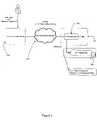
- Figure 1illustrates an architecture in which a server computer system 110 is connected, through a communications network 115, to a plurality of biological reagent instruments 120a - 120f
- the communications network 115may be a private local area network, a wide area network, the Internet, a virtual private network or any other kind of communications network, and may include either wireless or wired communication links, or both.
- LISlaboratory information system
- LIS'sare information systems maintained and controlled by laboratories that use biological reagent instruments to process tissue and other medical samples. LIS's often store patient data, including diagnostic tests or procedures that may need to be run on samples from specific patients. LIS's are typically off the shelf systems or systems that are customized to the needs of each laboratory.
- the biological reagent instruments 120a - 120fmay be any biological reagent instruments such as advanced staining instruments, autostainers, tissue processors, coverslippers and microarray (DNA, RNA, protein, tissue) instruments, although embodiments of the present invention are particularly suited for use with fully automated instruments, such as the BOND-MAX and Bond III immunohistochemistry and in-situ hybridisation instruments sold by Leica Microsystems, for example.
- the biological reagent instrumentsmay also include one or more of the various types of biological instruments.
- the biological reagent instruments of one embodiment of the inventionmay include a combination of advanced staining instruments and tissue processors. Descriptions of exemplary biological reagent instruments can be found in International Patent Application no. WO 2004/001390 A1 entitled "Biological Reaction Apparatus with Draining Mechanism" and in WO 2009/152569 entitled “Improvements in Staining Instruments and Methods", both in the name of the present applicant.
- the biological reagent instruments 120a - 120fmay be located in any site to which a computer network connection such as, but not limited to, an internet connection, data transfer connection, wired or wireless connection may be achieved.
- the biological reagent instruments 120a - 120fare located in in different laboratories located at the same or at different sites. It may be useful to have biological reagent instruments 120a - 120f spatially co-located in groups, such that a single operator has easy simultaneous physical access to a group of instruments 120a - 120f.
- Each of the biological reagent instruments 120a - 120fis controlled by the server computer system 110, and more specifically, an instrument communications component 110a of the server computer system 110.
- the instrument communications component 110asends instructions through the communications network 115 to the biological reagent instruments 120a - 120f, and receives messages (including status messages) from biological reagent instruments 120a - 120f.
- Server computer system 110can be of any configuration, including, for example, a single computer having at least one CPU, or multiple distributed multi-CPU machines acting in concert.
- the instrument communications component 110amay be a software application, a configurable hardware component such as a Field Programmable Gate Array (FPGA), or a dedicated hard ware component such as an Application Specific Integrated Circuit (ASIC) or any combination of these.
- FPGAField Programmable Gate Array
- ASICApplication Specific Integrated Circuit
- the server computer system 110also includes a user interface component 110b.
- the user interface component 110bgenerates and sends user interface (UI) instances to one or more client computer devices connected to the server computer system 110 by a communications link or network.
- the communications link or networkmay be the same network 115 by which the server computer system 110 communications with biological reagent instruments 120a - 120f (communications network 115), or may be a different communications link or network.
- Figure 1shows, as an example, two client computer devices 130a and 130b. Each UI instance is displayed on one or more display devices (eg video display units, monitors etc) (not shown) associated with a client computer device (130a, 130b). This enables a user at either client computer device 130a, 130b to interact with the corresponding UI instance, and therefore to interact with the server computer system 110, to send instructions to, and receive messages from, the one or more biological reagent instruments 120a - 120f.
- display deviceseg video display units, monitors etc
- the user interface component 110bmay generate and send the user interface instances indirectly by generating and sending to the one or more client computer devices 130a, 130b instructions for launching or generating the user interface instances.
- user interface component 110bmay generate and send user interface instances by generating and sending to the one or more client computer devices 130, 130b instructions for client software already installed at the one or more client computer devices (including, for example, instructions to the client software to launch a user interface instance).
- the server computer system 110may also be at any location, as long as it is connected, via one or more communications networks, to client computer devices 130, 130b and biological reagent instruments 120a-120f.
- a virtual podrepresents one or more of the biological reagent instruments 120a - 120f.
- Figure 1shows the biological reagent instruments 120a - 120f divided into two virtual pods, with biological reagent instruments 120a, 120b and 120c grouped into a first virtual pod 140a, and biological reagent instruments 120d, 120e and 120f grouped into a second virtual pod 140b.
- the UI instance invoked and sent by the clinical user interface 110b to client computer device 130ais used to control the first virtual pod 140a.
- the UI instance invoked and sent by the clinical user interface 110b to client computer device 130bis used to control the second virtual pod 140b.
- the size of the virtual podmay be of an unlimited scale. However, in practice the size of a virtual pod is usually based on the physical space available at each site, or by the number of biological reagent instruments that arc desired to be controlled by a single user or client computer device.
- a virtual podmay include more than 500 biological reagent instruments. In a further embodiment, a virtual pod may include from 250 to 500 biological reagent instruments. In one embodiment, a virtual pod may include from 100 to 250 biological reagent instruments. In a further embodiment, a virtual pod may include from 20 to 100 biological reagent instruments. In a further embodiment, a virtual pod may include 6 to 20 biological reagent instruments. In a further embodiment, a virtual pod may include from 1 to 5 biological reagent instruments.
- the biological reagent instruments 120a-120fmay be grouped into virtual pods on the basis of any criterion or criteria.
- commonly configured biological reagent instrumentsare grouped together in a virtual pod.
- biological reagent instruments 120a, 120b and 120cmay be configured exclusively to undertake research activities, virtual pod 140a becoming a "research pod”.
- biological reagent instruments 120d, 120e and 120fmay form a "clinical pod" 140b, each of the instruments 120d, 120e and 120f being configured to exclusively undertake clinical activities.
- client computer system 130acontrols, by means of the server computer system 110, the research pod 140a
- client computer system 130bcontrols, again by means of the server computer system 110, the clinical pod 140b.
- All of the members of the clinical pod 140bmay be configured to use only a predetermined set of procedures, being those procedures suitable for clinical activities.
- the research pod biological reagent instruments 120a, 120b and 120cmay be configured to use a predetermined set of reagents, some of which may be suitable for research use but have not yet been sufficiently tested for clinical use, and a predetermined set of procedures (again, some of which may not be suitable for clinical use).
- twenty biological reagent instrumentsmay be grouped into two virtual pods.
- a first virtual podmay contain nine biological reagent instruments used to assist with clinical diagnosis.
- the second virtual podmay contain eleven biological reagent instruments, used for research only.
- the biological reagent instruments in the first virtual podmay be configured to only run protocols or procedures that have been approved by an independent third party.
- twenty-five biological instrumentsmay be grouped into three virtual pods.
- the first virtual podmay be for test protocols and procedures, and the six biological instruments in this pod may be configured to use experimental procedures, possibly with experimental reagents.
- the second virtual podmay consist of ten biological reagent instruments used for clinical diagnosis.
- the third virtual podconsisting of nine biological reagent instruments, may be used for research purposes only.
- a virtual pod of five instrumentsmay consist of three instruments that are used for clinical diagnosis, and two instruments used for research purposes.
- virtual podsmay be of any size, and may consist of biological reagent instruments that are similarly configured, or alternatively may consist of biological reagent instruments that are otherwise related (for example, instruments in the same geographic location). Alternatively, the virtual pods may consist of biological reagent instruments that are not similarly configured or located in the same geographic location.
- the UI instance invoked and sent by the user interface component 110b to the client computer device (130a, 130b)may control one or more peripheral devices.
- the biological reagent instruments of the research pod 140a120a, 120b and 120c
- the biological reagent instruments of the research pod 140amay be commonly configured to use a common set of peripheral devices such, for example, a label printer 135a, standard printer, barcode scanner/reader 138a, RFID scanner/reader, biometric scanner/reader, and other digital imaging devices.
- the peripheral devices, such as the label printer 135a and barcode scanner 138amay be directly connected to the server computer system 110 through the communications network 115.
- the peripheral devicesmay be connected directly to the client computer device 130a. Regardless of how the peripheral devices are connected, they arc associated exclusively or non-exclusively with a corresponding virtual pod.
- the virtual pods 140a, 140bare defined by pod definition data, which is stored in a database component 110c of the server computer system 110.
- Pod definition dataincludes data identifying the specific biological reagent instruments 120a - 120f that are part of the pod.
- Pod definition datamay also include data identifying the peripheral devices for which the biological reagent instruments in the pod are configured.
- the pod definition datamay be modified by a user to reconfigure the membership and existence of virtual pods. This allows for dynamic grouping of biological reagent instruments 120a-120f, and virtual pod membership may be altered without reconfiguring any part of the biological reagent instruments 120a - 120f themselves.
- An example of a database schema for the pod definition datais shown in Figure 2 .
- the user interface component 110bmay request pod definition data from the database component 110c. This enables the user interface component 110b to include information about virtual pod membership in the one or more UI instances it generates. It also enables the user interface component 110b to bind specific UI instances to specific pods, which is done if a single specific UI instance is to control only a single corresponding virtual pod, or is to control a predetermined number of virtual pods.
- the server computer system 110is connected to LIS 125 through the communication network 115.
- the server computer system 110includes an LIS interface component 110d that enables the server computer system 110 to receive information from the LIS 125, thereby enabling the server computer system 110 to control the biological reagent instruments 120a-120f in accordance with appropriate protocols.
- the LIS 125may store patient data and the names of tests required to be applied to patient samples. In some configurations, it may store additional data, including protocol-related data.
- Users at client computer devices 130a and 130bmay be required to be authenticated in order to control any of the virtual pods 140a, 140b.
- the usermay enter their username and password (or other identification data) into the UI instance at the client computer device 130a, 130b.
- This identification datais sent to an authentication computer system.
- This authentication computer systemmay be in the form of a user management component 200, as illustrated in Figure 3 .
- User management component 200may be a component within server computer system 110. Alternatively, it may be or be part of a distinct computer system. In the latter case, the server computer system 110 may include an interception component 110e for intercepting any identification data sent to the server computer system 110 from a client computer device 130a, 130b, and redirecting (or resending) that identification data to the user management component 200.
- client computer devices 130a, 130bmay be configured to send identification data directly to the user management component 200, for example where the user management component 200 is a computer system distinct from the server computer system 110.
- the identification datamay be sent using HTTP Basic authentication, during a HTTPS session.
- HTTP Basic authenticationmay be used instead of Basic authentication, again preferably over an HTTPS session.
- Digest authentication or Form-Based authenticationmay be used instead of Basic authentication, again preferably over an HTTPS session.
- the authentication computer systemmay be an existing system that at least in part operates independently of the server computer system 110, such as an Active Directory authentication system, or an authentication system that uses LDAP lookups. Such systems may already be operational and in place at the laboratory, and may be reconfigured to operate as described above.
- the user management component 200Upon receipt of the identification data, the user management component 200 invokes the execution of an authentication process to generate credential data for authenticating the client computer device for a communications session with the server computer system 110, the communications session enabling a user at the client computer device to control one or more biological reagent instruments in one or more virtual pods.
- the credential datais sent to the server computer system 110.
- authentication computer systemuser management component 200
- authentication and user detailsneed not be stored in the server computer system 110 (where the authentication computer system 200 is distinct from the server computer system 110), or may be compartmentalised in a separate component (where the authentication computer system is a sub-system of computer system 110).
- the user interface component 110bis a web server, such as the Apache HTTP Server, which may execute scripts (such as those written in PHP), and can read to or write from database storage using an appropriate language, such as SQL.
- the user interface componentreceives HTTP requests including user credentials in the HTTP Authentication header. These requests are redirected to, and authenticated by, the authentication computer system 200 before the HTTP requests are passed on to the server computer system 110.
- the UI instancesmay be rendered at the client computer device 130a, 130b using a standard web browser application.
- the user interface instancesmay take the form of a markup language such as HTML or XML, together with scripts such as those written in PHP or JavaScript.
- a suitable application frameworksuch as Microsoft Silverlight or Adobe Flash may be used.
- the user interface component 110bmay not be a web server, and may be a UI server which modifies the behaviour or appearance of user interface instances created by software executing on the client computer devices 130a, 130b.
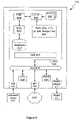
- Figure 4illustrates a process that may be undertaken by server computer system 110 to generate a user-interface instance for use by a client computer device (for example, client computer device 130a) to control, through a communications network 115, a virtual pod 140a, 140b representing one or more biological reagent instruments 120a-120f.
- the server computer system 110receives from the client computer device 130a a request for the UI instance.
- the client computer device 130amay generate this request automatically upon booting up of the client computer device 130a.
- the requestmay be generated upon the launch of a dedicated application, or a standard web browser application, on client computer device 130a.
- the server computer system 110In response to the request, at step 305, the server computer system 110 generates and sends a first UI instance to the client computer device 130a through communications network 115. This may involve the server computer 110 sending instructions to the client computer device 130a to launch a first UI instance generated at the client computer device 130a.
- the first UI instanceprompts the user to enter identification data unique to the user (for example, a username and password). As discussed above, this identification data is sent to an authentication computer system 200 (either directly, or through a redirection).
- the server computer system 110receives from the user management component 200, at step 310, credential data for authenticating the client computer device 130a.
- the authentication of the client computer device 130ais a substitute for authenticating the user directly, the authentication enabling the client computer device 130a, on instructions from the user, to control one or more biological reagent instruments 120a - 120f in a virtual pod.
- Each user of the server computer system 110is associated with one or more roles. Each role is associated with rule data that identifies the actions that are allowed to be performed by users having that role, and the results data visible to users having the role.
- the server computer system 110retrieves the user-specific information (for example, role information) from a database component (for example, database 110c, or another database) (step 315).
- the server computer system 110also retrieves from the database (for example, database 110c), at step 320, virtual pod definitions (in the form of pod definition data) using the user-specific information.
- the virtual pod definitions that are retrievedare only those definitions for virtual pods associated with a specific user (or a specific role associated with the user).
- the user interface component 110b of the server computer system 110generates and sends to the client computer device 130a the user-interface instance based on the user-specific information and the one or more virtual pod definitions, the user-interface instance enabling a user at the client computer device 130a to control only the virtual pods defined by the (retrieved) virtual pod definitions,
- the user interface component 110btailors the user interface instance by only showing (or enabling the activation of) user interface elements for actions that the user is able to lake (based on the user or the role definitions associated with the user), and only showing information relating to virtual pods that the user has the authority to control.
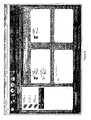
- An example screenshot of a user interface, showing the virtual pods that the user has the authority to control,is shown in Figure 5 .
- the user interfaceshows only, for each virtual pod over which the user has control:
- the server computer system 110is a standard computer system such as an 32-bit or 64-bit Intel Architecture based computer system, as shown in Figure 6 , and the process described above with reference to Figure 4 executed by the server computer system 110 is implemented in the form of programming instructions of one or more software modules 602 stored on non-volatile (e.g., hard disk) storage 604 associated with the computer system, as shown in Figure 6 .
- non-volatile (e.g., hard disk) storage 604associated with the computer system, as shown in Figure 6 .
- ASICsapplication-specific integrated circuits
- FPGAsfield programmable gate arrays
- the server computer system 110includes standard computer components, including random access memory (RAM) 606, at least one processor 608, and external interfaces 610, 612, 614, all interconnected by a bus 616.
- the external interfacesinclude universal serial bus (USB) interfaces 610, at least one of which is connected to a keyboard and a pointing device such as a mouse 618, a network interface connector (NIC) 612 which connects the system 110 to a communications network 115, and a display adapter 614, which is connected to a display device such as an LCD panel display 622.
- USBuniversal serial bus
- NICnetwork interface connector
- the system 110also includes a number of standard software modules 626 to 630, including an operating system 624 such as Linux or Microsoft Windows, web server software 626 such as Apache, available at http://www.apache.org , scripting language support 628 such as PHP, available at http://www.php.net, or Microsoft ASP, and structured query language (SQL) support 630 such as MySQL, available from http://www.mysql.com, which allows data to be stored in and retrieved from an SQL database 632.
- an operating system 624such as Linux or Microsoft Windows
- web server software 626such as Apache, available at http://www.apache.org
- scripting language support 628such as PHP, available at http://www.php.net, or Microsoft ASP
- SQLstructured query language
- the web server 626, scripting language 628, and SQL modules 630provide the system 110 with the general ability to allow client computing devices 130a, 130b equipped with standard web browser software to access the system 110 and in particular to provide data to and receive data from the database 632.
- scripts accessible by the web server 626including the one or more software modules 602 implementing the process described above with reference to Figure 4 , and also any other scripts and supporting data 634, including markup language (e.g., HTML, XML) scripts, PHP (or ASP), and/or CGI scripts, image files, style sheets, and the like.
- markup languagee.g., HTML, XML
- PHPor ASP
- CGI scriptsimage files, style sheets, and the like.
Landscapes
- Engineering & Computer Science (AREA)
- Health & Medical Sciences (AREA)
- General Health & Medical Sciences (AREA)
- Medical Informatics (AREA)
- Biomedical Technology (AREA)
- Primary Health Care (AREA)
- Public Health (AREA)
- Epidemiology (AREA)
- General Business, Economics & Management (AREA)
- Business, Economics & Management (AREA)
- Computer Networks & Wireless Communication (AREA)
- Signal Processing (AREA)
- Computing Systems (AREA)
- General Engineering & Computer Science (AREA)
- Physics & Mathematics (AREA)
- General Physics & Mathematics (AREA)
- Automation & Control Theory (AREA)
- Automatic Analysis And Handling Materials Therefor (AREA)
- User Interface Of Digital Computer (AREA)
Description
- The present invention relates to a laboratory instrument control system, and in particular to a network control system for controlling biological reagent instruments.
- Computer-based control systems have been developed to directly control biological reagent instruments. The instruments are used to automatically apply biological reagents to samples, tissue samples in particular, placed on slides held by the instruments. Instruments of this type are described in International Patent Publications
WO 04/001390 WO 04/08857 - There are a number of technical problems and limitations associated with existing control systems. For example, the pods are isolated from each other, and there is no communication or data sharing between them. A user of a control system also has to attend a laboratory and the location of the control system and pod to effect control and operate the system. Laboratory Information Systems (LIS's) also are required to be independently connected to the control system of each pod.
US 2002/0072048 A1 discloses a server computer system for providing user interfaces at client computer devices in order to control virtual pods. In contrast to the present invention, it does not relate to biological reagent instruments processing tissue samples and which are located in different laboratories, it does also not receive control information from a laboratory information system storing patient data and the names of tests required to be applied to patient samples, and not all of its instruments are configured to exclusively perform at least one specific task or type of task.- It is desired to alleviate one or more difficulties with the prior art, or at least provide a useful alternative.
- The present invention provides a server computer system connected to a first communications network and a method of generating a user-interface (UI) instance for use by a client computer device, according to the independent claims.
- Some embodiments of the present invention are described herein, by way of example only, with reference to the accompanying drawings, wherein:
Figure 1 is an architecture diagram illustrating a communications network connected to a number of peripheral devices.Figure 2 is a data schema for virtual pod definition data.Figure 3 is an architecture diagram illustrating a client device connected to an authentication computer system.Figure 4 illustrates a process that may be undertaken by a server computer system to generate a user-interface instance for use by a client computer device.Figure 5 is an illustration of an exemplary user interface.Figure 6 is an illustration of an exemplary architecture of a server computer system configured to generate a user-interface instance for use by a client computer device.- The examples, aspects and embodiments, if any, disclosed in the following description that do not fall within the scope of the claims are for reference only, and are to be interpreted as examples useful for understanding various embodiments of the invention.
Figure 1 illustrates an architecture in which aserver computer system 110 is connected, through acommunications network 115, to a plurality ofbiological reagent instruments 120a - 120f, Thecommunications network 115 may be a private local area network, a wide area network, the Internet, a virtual private network or any other kind of communications network, and may include either wireless or wired communication links, or both. Also connected. to thecommunications network 115 is a laboratory information system (LIS) 125.- LIS's are information systems maintained and controlled by laboratories that use biological reagent instruments to process tissue and other medical samples. LIS's often store patient data, including diagnostic tests or procedures that may need to be run on samples from specific patients. LIS's are typically off the shelf systems or systems that are customized to the needs of each laboratory.
- The
biological reagent instruments 120a - 120f may be any biological reagent instruments such as advanced staining instruments, autostainers, tissue processors, coverslippers and microarray (DNA, RNA, protein, tissue) instruments, although embodiments of the present invention are particularly suited for use with fully automated instruments, such as the BOND-MAX and Bond III immunohistochemistry and in-situ hybridisation instruments sold by Leica Microsystems, for example. The biological reagent instruments may also include one or more of the various types of biological instruments. For example, the biological reagent instruments of one embodiment of the invention may include a combination of advanced staining instruments and tissue processors. Descriptions of exemplary biological reagent instruments can be found in International Patent Application no.WO 2004/001390 A1 entitled "Biological Reaction Apparatus with Draining Mechanism" and inWO 2009/152569 entitled "Improvements in Staining Instruments and Methods", both in the name of the present applicant. - The
biological reagent instruments 120a - 120f may be located in any site to which a computer network connection such as, but not limited to, an internet connection, data transfer connection, wired or wireless connection may be achieved. Thebiological reagent instruments 120a - 120f are located in in different laboratories located at the same or at different sites. It may be useful to havebiological reagent instruments 120a - 120f spatially co-located in groups, such that a single operator has easy simultaneous physical access to a group ofinstruments 120a - 120f. - Each of the
biological reagent instruments 120a - 120f is controlled by theserver computer system 110, and more specifically, an instrument communications component 110a of theserver computer system 110. The instrument communications component 110a sends instructions through thecommunications network 115 to thebiological reagent instruments 120a - 120f, and receives messages (including status messages) frombiological reagent instruments 120a - 120f.Server computer system 110 can be of any configuration, including, for example, a single computer having at least one CPU, or multiple distributed multi-CPU machines acting in concert. The instrument communications component 110a may be a software application, a configurable hardware component such as a Field Programmable Gate Array (FPGA), or a dedicated hard ware component such as an Application Specific Integrated Circuit (ASIC) or any combination of these. - The
server computer system 110 also includes auser interface component 110b. Theuser interface component 110b generates and sends user interface (UI) instances to one or more client computer devices connected to theserver computer system 110 by a communications link or network. The communications link or network may be thesame network 115 by which theserver computer system 110 communications withbiological reagent instruments 120a - 120f (communications network 115), or may be a different communications link or network.Figure 1 shows, as an example, twoclient computer devices client computer device server computer system 110, to send instructions to, and receive messages from, the one or morebiological reagent instruments 120a - 120f. - The
user interface component 110b may generate and send the user interface instances indirectly by generating and sending to the one or moreclient computer devices user interface component 110b may generate and send user interface instances by generating and sending to the one or moreclient computer devices 130, 130b instructions for client software already installed at the one or more client computer devices (including, for example, instructions to the client software to launch a user interface instance). - The
server computer system 110 may also be at any location, as long as it is connected, via one or more communications networks, toclient computer devices 130, 130b andbiological reagent instruments 120a-120f. - Each UI instance controls a respective virtual pod. A virtual pod represents one or more of the
biological reagent instruments 120a - 120f.Figure 1 shows thebiological reagent instruments 120a - 120f divided into two virtual pods, withbiological reagent instruments biological reagent instruments virtual pod 140b. The UI instance invoked and sent by theclinical user interface 110b toclient computer device 130a is used to control the first virtual pod 140a. Similarly, the UI instance invoked and sent by theclinical user interface 110b toclient computer device 130b is used to control the secondvirtual pod 140b. In a general sense, the size of the virtual pod may be of an unlimited scale. However, in practice the size of a virtual pod is usually based on the physical space available at each site, or by the number of biological reagent instruments that arc desired to be controlled by a single user or client computer device. - In one embodiment, a virtual pod may include more than 500 biological reagent instruments. In a further embodiment, a virtual pod may include from 250 to 500 biological reagent instruments. In one embodiment, a virtual pod may include from 100 to 250 biological reagent instruments. In a further embodiment, a virtual pod may include from 20 to 100 biological reagent instruments. In a further embodiment, a virtual pod may include 6 to 20 biological reagent instruments. In a further embodiment, a virtual pod may include from 1 to 5 biological reagent instruments.
- The
biological reagent instruments 120a-120f may be grouped into virtual pods on the basis of any criterion or criteria. In some embodiments, commonly configured biological reagent instruments are grouped together in a virtual pod. For example,biological reagent instruments biological reagent instruments instruments client computer system 130a controls, by means of theserver computer system 110, the research pod 140a, whileclient computer system 130b controls, again by means of theserver computer system 110, theclinical pod 140b. All of the members of theclinical pod 140b (namelybiological reagent instruments biological reagent instruments - As one example, twenty biological reagent instruments may be grouped into two virtual pods. A first virtual pod may contain nine biological reagent instruments used to assist with clinical diagnosis. The second virtual pod may contain eleven biological reagent instruments, used for research only. The biological reagent instruments in the first virtual pod may be configured to only run protocols or procedures that have been approved by an independent third party.
- In another example, twenty-five biological instruments may be grouped into three virtual pods. The first virtual pod may be for test protocols and procedures, and the six biological instruments in this pod may be configured to use experimental procedures, possibly with experimental reagents. The second virtual pod may consist of ten biological reagent instruments used for clinical diagnosis. The third virtual pod, consisting of nine biological reagent instruments, may be used for research purposes only.
- In a further example, a virtual pod of five instruments may consist of three instruments that are used for clinical diagnosis, and two instruments used for research purposes.
- As indicated above, virtual pods may be of any size, and may consist of biological reagent instruments that are similarly configured, or alternatively may consist of biological reagent instruments that are otherwise related (for example, instruments in the same geographic location). Alternatively, the virtual pods may consist of biological reagent instruments that are not similarly configured or located in the same geographic location.
- In addition to controlling a virtual pod representing a group of biological reagent instruments, the UI instance invoked and sent by the
user interface component 110b to the client computer device (130a, 130b) may control one or more peripheral devices. For example, the biological reagent instruments of the research pod 140a (120a, 120b and 120c) may be commonly configured to use a common set of peripheral devices such, for example, alabel printer 135a, standard printer, barcode scanner/reader 138a, RFID scanner/reader, biometric scanner/reader, and other digital imaging devices. The peripheral devices, such as thelabel printer 135a andbarcode scanner 138a may be directly connected to theserver computer system 110 through thecommunications network 115. Alternatively, the peripheral devices may be connected directly to theclient computer device 130a. Regardless of how the peripheral devices are connected, they arc associated exclusively or non-exclusively with a corresponding virtual pod. - The
virtual pods 140a, 140b are defined by pod definition data, which is stored in a database component 110c of theserver computer system 110. Pod definition data includes data identifying the specificbiological reagent instruments 120a - 120f that are part of the pod. Pod definition data may also include data identifying the peripheral devices for which the biological reagent instruments in the pod are configured. The pod definition data may be modified by a user to reconfigure the membership and existence of virtual pods. This allows for dynamic grouping ofbiological reagent instruments 120a-120f, and virtual pod membership may be altered without reconfiguring any part of thebiological reagent instruments 120a - 120f themselves. An example of a database schema for the pod definition data is shown inFigure 2 . - The
user interface component 110b may request pod definition data from the database component 110c. This enables theuser interface component 110b to include information about virtual pod membership in the one or more UI instances it generates. It also enables theuser interface component 110b to bind specific UI instances to specific pods, which is done if a single specific UI instance is to control only a single corresponding virtual pod, or is to control a predetermined number of virtual pods. - To enable the execution of appropriate sample processing protocols, as described above the
server computer system 110 is connected toLIS 125 through thecommunication network 115. Theserver computer system 110 includes an LIS interface component 110d that enables theserver computer system 110 to receive information from theLIS 125, thereby enabling theserver computer system 110 to control thebiological reagent instruments 120a-120f in accordance with appropriate protocols. TheLIS 125 may store patient data and the names of tests required to be applied to patient samples. In some configurations, it may store additional data, including protocol-related data. - Users at
client computer devices virtual pods 140a, 140b. The user may enter their username and password (or other identification data) into the UI instance at theclient computer device user management component 200, as illustrated inFigure 3 .User management component 200 may be a component withinserver computer system 110. Alternatively, it may be or be part of a distinct computer system. In the latter case, theserver computer system 110 may include aninterception component 110e for intercepting any identification data sent to theserver computer system 110 from aclient computer device user management component 200. Alternatively,client computer devices user management component 200, for example where theuser management component 200 is a computer system distinct from theserver computer system 110. - Where the UI instances are displayed on the
client computer device - The authentication computer system may be an existing system that at least in part operates independently of the
server computer system 110, such as an Active Directory authentication system, or an authentication system that uses LDAP lookups. Such systems may already be operational and in place at the laboratory, and may be reconfigured to operate as described above. - Upon receipt of the identification data, the
user management component 200 invokes the execution of an authentication process to generate credential data for authenticating the client computer device for a communications session with theserver computer system 110, the communications session enabling a user at the client computer device to control one or more biological reagent instruments in one or more virtual pods. The credential data is sent to theserver computer system 110. - By having a separate authentication computer system (user management component 200) undertake the task of user authentication, authentication and user details need not be stored in the server computer system 110 (where the
authentication computer system 200 is distinct from the server computer system 110), or may be compartmentalised in a separate component (where the authentication computer system is a sub-system of computer system 110). - In one embodiment, the
user interface component 110b is a web server, such as the Apache HTTP Server, which may execute scripts (such as those written in PHP), and can read to or write from database storage using an appropriate language, such as SQL. In such an embodiment, the user interface component receives HTTP requests including user credentials in the HTTP Authentication header. These requests are redirected to, and authenticated by, theauthentication computer system 200 before the HTTP requests are passed on to theserver computer system 110. - Where the
user interface component 110b is a web server, the UI instances may be rendered at theclient computer device - As described above, in other embodiments the
user interface component 110b may not be a web server, and may be a UI server which modifies the behaviour or appearance of user interface instances created by software executing on theclient computer devices Figure 4 illustrates a process that may be undertaken byserver computer system 110 to generate a user-interface instance for use by a client computer device (for example,client computer device 130a) to control, through acommunications network 115, avirtual pod 140a, 140b representing one or morebiological reagent instruments 120a-120f. Atstep 300, theserver computer system 110 receives from theclient computer device 130a a request for the UI instance. Theclient computer device 130a may generate this request automatically upon booting up of theclient computer device 130a. Alternatively, the request may be generated upon the launch of a dedicated application, or a standard web browser application, onclient computer device 130a. In response to the request, atstep 305, theserver computer system 110 generates and sends a first UI instance to theclient computer device 130a throughcommunications network 115. This may involve theserver computer 110 sending instructions to theclient computer device 130a to launch a first UI instance generated at theclient computer device 130a. The first UI instance prompts the user to enter identification data unique to the user (for example, a username and password). As discussed above, this identification data is sent to an authentication computer system 200 (either directly, or through a redirection).- The
server computer system 110 receives from theuser management component 200, atstep 310, credential data for authenticating theclient computer device 130a. The authentication of theclient computer device 130a is a substitute for authenticating the user directly, the authentication enabling theclient computer device 130a, on instructions from the user, to control one or morebiological reagent instruments 120a - 120f in a virtual pod. - Each user of the
server computer system 110 is associated with one or more roles. Each role is associated with rule data that identifies the actions that are allowed to be performed by users having that role, and the results data visible to users having the role. Theserver computer system 110 retrieves the user-specific information (for example, role information) from a database component (for example, database 110c, or another database) (step 315). Theserver computer system 110 also retrieves from the database (for example, database 110c), atstep 320, virtual pod definitions (in the form of pod definition data) using the user-specific information. The virtual pod definitions that are retrieved are only those definitions for virtual pods associated with a specific user (or a specific role associated with the user). - At
step 325, theuser interface component 110b of theserver computer system 110 generates and sends to theclient computer device 130a the user-interface instance based on the user-specific information and the one or more virtual pod definitions, the user-interface instance enabling a user at theclient computer device 130a to control only the virtual pods defined by the (retrieved) virtual pod definitions, Theuser interface component 110b tailors the user interface instance by only showing (or enabling the activation of) user interface elements for actions that the user is able to lake (based on the user or the role definitions associated with the user), and only showing information relating to virtual pods that the user has the authority to control. An example screenshot of a user interface, showing the virtual pods that the user has the authority to control, is shown inFigure 5 . Preferably, the user interface shows only, for each virtual pod over which the user has control: - the instruments allocated to that virtual pod;
- the cases and slides that arc being processed on that virtual pod;
- the maintenance schedule for the instruments in that virtual pod;
- the test procedures and reagents that are allowed to be used on that virtual pod.
- In the described embodiment, the
server computer system 110 is a standard computer system such as an 32-bit or 64-bit Intel Architecture based computer system, as shown inFigure 6 , and the process described above with reference toFigure 4 executed by theserver computer system 110 is implemented in the form of programming instructions of one ormore software modules 602 stored on non-volatile (e.g., hard disk)storage 604 associated with the computer system, as shown inFigure 6 . However, it will be apparent that at least parts of the process described above with reference toFigure 4 could alternatively be implemented as one or more dedicated hardware components, such as application-specific integrated circuits (ASICs) and/or field programmable gate arrays (FPGAs). - The
server computer system 110 includes standard computer components, including random access memory (RAM) 606, at least oneprocessor 608, andexternal interfaces system 110 to acommunications network 115, and adisplay adapter 614, which is connected to a display device such as anLCD panel display 622. - The
system 110 also includes a number ofstandard software modules 626 to 630, including anoperating system 624 such as Linux or Microsoft Windows,web server software 626 such as Apache, available athttp://www.apache.org,scripting language support 628 such as PHP, available at http://www.php.net, or Microsoft ASP, and structured query language (SQL)support 630 such as MySQL, available from http://www.mysql.com, which allows data to be stored in and retrieved from anSQL database 632. - Together, the
web server 626,scripting language 628, andSQL modules 630 provide thesystem 110 with the general ability to allowclient computing devices system 110 and in particular to provide data to and receive data from thedatabase 632. - However, it will be understood by those skilled in the art that the specific functionality provided by the
system 110 to such users is provided by scripts accessible by theweb server 626, including the one ormore software modules 602 implementing the process described above with reference toFigure 4 , and also any other scripts and supportingdata 634, including markup language (e.g., HTML, XML) scripts, PHP (or ASP), and/or CGI scripts, image files, style sheets, and the like. - The use of virtual pods, as described above, has at least the following advantages:
- laboratory users can easily configure and reconfigure groups of laboratory reagent instruments and associated peripheral devices without having to physically re-connect or rewire instruments or peripheral devices;
- instruments and peripheral devices may be physically moved without the need for any reconfiguration;
- users can be assigned pods having instruments configured appropriately to their role and/or experience;
- users are presented with a user interface uncluttered by instruments and functions to which they do not have access;
- reagents can be restricted to specific instruments; for example reagents for research purposes can be restricted to research only instruments (that may form a research-only virtual pod); or tests approved by government agencies (such as the United States Food and Drug Administration) may only run on certified instruments or instruments listed in the government registration for that particular test; and
- tests can be allocated (and confined) to instruments which have been the subject of regulatory approval.
- Many modifications will be apparent to those skilled in the art without parting from the scope of the present invention.
- The reference in this specification to any prior publication (or information derived from it), or to any matter which is known, is not, and should not be taken as an acknowledgment or admission or any form of suggestion that that prior publication (or information derived from it) or known matter forms part of the common general knowledge in the field of endeavour to which this specification relates.
Claims (10)
- A server computer system (110) connected to a first communications network (115) and including:an instrument communications component (110a) configured to communicate with and control a plurality of biological reagent instruments (120a - 120f) using the first communications network (115), said control exercised according to laboratory information received from a laboratory information system (125) connected to the first communications network (115), wherein the biological reagent instruments (120a - 120f) are configured to process tissue samples, wherein the laboratory information system (125) stores patient data and the names of tests required to be applied to patient samples; anda user interface component (110b) configured to cause, upon receiving a request, user interface instances to be displayed by a client computer device (130a, 130b) connected by a second communications network (115) to said server computer system (110), one of the user interfaceinstances enabling a user to enter identification data of the user;wherein said user interface instances enable a user at the client computer device (130a, 130b) to control respective virtual pods (140a, 140b) via communication with the server computer system (110) over the second communications network (115), with each virtual pod (140a, 140b) representing more than one of said biological reagent instruments;wherein the biological reagent instruments of each virtual pod are located in different laboratories,such that the control of the virtual pod (140a, 140b) by the user causes the instrument communications component (110a) to correspondingly communicate with and control the more than one biological reagent instruments (120a -120f) represented by said controlled virtual pod (140a, 140b) according to said laboratory information,wherein all of the more than one biological reagent instruments represented by said controlled virtual pod are configured to exclusively perform at least one specific task or type of task and to use one or more of:a predetermined set of reagents;a predetermined set of procedures; anda common set of peripheral devices (135a, 138a);the server computer system (110) further including a laboratory information system interface component (110d) configured to interface with, and receive the laboratory information from the laboratory information system (125), the laboratory information relating to the configuration and/or operation of one or more of the virtual pods (140a, 140b),the server computer system (110) including a user management component (200) and a database component (110c) configured to store pod definition data representing one or more virtual pod definitions, the server computer system (110) being configured to receive, from the user management component, credential data for authenticating the client computer device (130a, 130b), and to retrieve user-specific information from the database component (110c) using the credential data, and to retrieve from said database component (110c) one or more virtual pod definitions using the retrieved user-specific information.
- A server computer system as claimed in claim 1, wherein the different laboratories are located at different sites.
- A server computer system as claimed in claim 1 or 2, wherein the common set of peripheral devices includes one or more of:a label printer (135a); anda barcode scanner (138a).
- A server computer system as claimed in any one of the preceding claims, wherein the database component (110c) provides the pod definition data to the user interface component (110b) on request by the user interface component.
- A server computer system as claimed in any one of the preceding claims, wherein the user interface component (110b) is configured to generate and send user interface instances to be rendered at the client computer (130a, 130b) device using a web browser.
- A server computer system as claimed in any one of claims 1-5 wherein the user interface component (110b) generates and sends instructions to the client computer device (130a, 130b) to launch, or modify the behaviour or appearance of, a user interface generated at the client computer device (130a, 130b).
- A server computer system as claimed in any one of the preceding claims, wherein the biological reagent instruments are fully automated instruments.
- A server computer system as claimed in any one of the preceding claims, wherein the biological reagent instruments are any one or more of advanced staining instruments, autostainers, tissue processors, coverslippers and microarray instruments.
- A server computer system as claimed in any one of the preceding claims, wherein the virtual pod includes from 250 to 500, from 100 to 250, from 20 to 100, from 6 to 20, or up to 5 biological reagent instruments.
- A method of generating a user-interface instance for use by a client computer device (130a, 130b) to control, through a server computer system (110) connected to the client computer device over a communications network (115), a virtual pod (140a, 140b) representing more than one biological reagent instruments (120a - 120f), wherein the biological reagent instruments (120a - 120f) are configured to process tissue samples, said control exercised according to laboratory information received from a laboratory information system (125) connected to the communications network (115), wherein the laboratory information system (125) stores patient data and the names of tests required to be applied to patient samples, the server computer system (110) including a laboratory information system interface component (110d) configured to interface with, and receive the laboratory information from the laboratory information system (125), the laboratory information relating to the configuration and/or operation of one or more of the virtual pods (140a, 140b), the method including the steps of:receiving from the client computer device (130a, 130b) through the communications network (115) a request for the user interface instance;generating and sending a first user interfaceinstance to the client computer device (130a, 130b) through the communications network (115), the first user interface instance enabling a user to enter identification data of the user;receiving, from a user management component, credential data for authenticating the client computer device (130a, 130b);retrieving user-specific information from a database component (110c) using the credential data, and retrieving from said or another database component (110c) one or more virtual pod definitions using the retrieved user-specific information;generating and sending to the client computer device (130a, 130b) the user-interface instance based on the user-specific information and the one or more virtual pod definitions, the user-interface instance enabling a user at the client computer device to control only the virtual pods (140a, 140b) defined by the virtual pod definitions via communication with the server computer system (110), such that the control of a virtual pod by the user causes the server computer system to engage in corresponding communication with and control of the more than one biological reagent instruments (120a - 120f) represented by said controlled virtual pod (140a, 140b) according to said laboratory information,wherein all of the more than one biological reagent instruments represented by said controlled virtual pod are configured to exclusively perform at least one specific task or type of task, and to use one or more of:a predetermined set of reagents;a predetermined set of procedures; anda common set of peripheral devices (135a, 138a);and wherein the biological reagent instruments of each virtual pod are located in different laboratories.
Applications Claiming Priority (2)
| Application Number | Priority Date | Filing Date | Title |
|---|---|---|---|
| US201161579409P | 2011-12-22 | 2011-12-22 | |
| PCT/AU2012/001606WO2013091026A1 (en) | 2011-12-22 | 2012-12-21 | Laboratory instrument control system |
Publications (3)
| Publication Number | Publication Date |
|---|---|
| EP2795497A1 EP2795497A1 (en) | 2014-10-29 |
| EP2795497A4 EP2795497A4 (en) | 2015-09-02 |
| EP2795497B1true EP2795497B1 (en) | 2022-05-04 |
Family
ID=48667528
Family Applications (1)
| Application Number | Title | Priority Date | Filing Date |
|---|---|---|---|
| EP12859708.5AActiveEP2795497B1 (en) | 2011-12-22 | 2012-12-21 | Laboratory instrument control system |
Country Status (4)
| Country | Link |
|---|---|
| US (3) | US10054913B2 (en) |
| EP (1) | EP2795497B1 (en) |
| AU (3) | AU2012357656A1 (en) |
| WO (1) | WO2013091026A1 (en) |
Families Citing this family (4)
| Publication number | Priority date | Publication date | Assignee | Title |
|---|---|---|---|---|
| EP2795497B1 (en)* | 2011-12-22 | 2022-05-04 | Leica Biosystems Melbourne Pty Ltd | Laboratory instrument control system |
| US9785560B2 (en)* | 2013-04-19 | 2017-10-10 | Salesforce.Com, Inc. | Scene-isolated internet application |
| JP6101230B2 (en)* | 2014-03-28 | 2017-03-22 | シスメックス株式会社 | ANALYZER SYSTEM, PROCESSING METHOD, AND COMPUTER PROGRAM |
| CN114999262A (en)* | 2022-07-12 | 2022-09-02 | 东莞职业技术学院 | Industrial internet practical training system based on OPC-UA |
Family Cites Families (22)
| Publication number | Priority date | Publication date | Assignee | Title |
|---|---|---|---|---|
| US5532941A (en)* | 1994-07-08 | 1996-07-02 | Lin; Lawrence I. | Inter-laboratory performance monitoring system |
| US5841975A (en)* | 1996-12-10 | 1998-11-24 | The Regents Of The University Of California | Method and apparatus for globally-accessible automated testing |
| US6802053B1 (en)* | 1997-08-18 | 2004-10-05 | National Instruments Corporation | Graphical programming system with distributed block diagram execution and front panel display |
| US6085227A (en)* | 1998-03-20 | 2000-07-04 | International Business Machines Corporation | System and method for operating scientific instruments over wide area networks |
| ITMI981528A1 (en)* | 1998-07-03 | 2000-01-03 | Recordati Ind Chimica E Farma | TOPICAL FORMULATIONS OF ACICLOVIR |
| US6514085B2 (en) | 1999-07-30 | 2003-02-04 | Element K Online Llc | Methods and apparatus for computer based training relating to devices |
| US7555492B2 (en)* | 1999-11-05 | 2009-06-30 | The Board Of Trustees At The Leland Stanford Junior University | System and method for internet-accessible tools and knowledge base for protocol design, metadata capture and laboratory experiment management |
| US7010448B1 (en)* | 2000-03-06 | 2006-03-07 | Bio-Rad Laboratories, Inc. | Method and structure for mitigating instrumentation differences |
| US6937323B2 (en)* | 2000-11-08 | 2005-08-30 | Burstein Technologies, Inc. | Interactive system for analyzing biological samples and processing related information and the use thereof |
| US20020156756A1 (en)* | 2000-12-06 | 2002-10-24 | Biosentients, Inc. | Intelligent molecular object data structure and method for application in heterogeneous data environments with high data density and dynamic application needs |
| US8099257B2 (en)* | 2001-08-24 | 2012-01-17 | Bio-Rad Laboratories, Inc. | Biometric quality control process |
| US7491367B2 (en)* | 2002-06-04 | 2009-02-17 | Applera Corporation | System and method for providing a standardized state interface for instrumentation |
| US20060120921A1 (en) | 2002-06-20 | 2006-06-08 | Stuart Elliot | Biological reaction apparatus with draining mechanism |
| WO2004008857A1 (en) | 2002-07-18 | 2004-01-29 | Basf Aktiengesellschaft | Fungicidal mixtures |
| US7661127B2 (en)* | 2002-11-12 | 2010-02-09 | Millipore Corporation | Instrument access control system |
| US20040093516A1 (en)* | 2002-11-12 | 2004-05-13 | Hornbeek Marc William Anthony | System for enabling secure remote switching, robotic operation and monitoring of multi-vendor equipment |
| US7860727B2 (en)* | 2003-07-17 | 2010-12-28 | Ventana Medical Systems, Inc. | Laboratory instrumentation information management and control network |
| US20060264749A1 (en)* | 2004-11-24 | 2006-11-23 | Weiner Allison L | Adaptable user interface for diagnostic imaging |
| US8041437B2 (en)* | 2008-04-15 | 2011-10-18 | International Business Machines Corporation | System and method for virtual control of laboratory equipment |
| JP2011174844A (en)* | 2010-02-25 | 2011-09-08 | Sysmex Corp | Clinical test information managing device, clinical inspection information management system, and computer program |
| EP2616925A4 (en)* | 2010-09-16 | 2014-02-12 | Omnyx LLC | Histology workflow management system |
| EP2795497B1 (en)* | 2011-12-22 | 2022-05-04 | Leica Biosystems Melbourne Pty Ltd | Laboratory instrument control system |
- 2012
- 2012-12-21EPEP12859708.5Apatent/EP2795497B1/enactiveActive
- 2012-12-21USUS14/366,814patent/US10054913B2/enactiveActive
- 2012-12-21AUAU2012357656Apatent/AU2012357656A1/ennot_activeAbandoned
- 2012-12-21WOPCT/AU2012/001606patent/WO2013091026A1/enactiveApplication Filing
- 2018
- 2018-08-03USUS16/054,545patent/US10579029B2/enactiveActive
- 2018-08-03USUS16/054,571patent/US11550275B2/enactiveActive
- 2018-10-17AUAU2018250415Apatent/AU2018250415A1/ennot_activeAbandoned
- 2020
- 2020-12-14AUAU2020286340Apatent/AU2020286340B2/enactiveActive
Also Published As
| Publication number | Publication date |
|---|---|
| AU2020286340B2 (en) | 2022-12-08 |
| AU2018250415A1 (en) | 2018-11-08 |
| US20180341238A1 (en) | 2018-11-29 |
| US20180341237A1 (en) | 2018-11-29 |
| AU2020286340A1 (en) | 2021-01-21 |
| EP2795497A4 (en) | 2015-09-02 |
| US10054913B2 (en) | 2018-08-21 |
| US20140371884A1 (en) | 2014-12-18 |
| AU2012357656A1 (en) | 2014-07-24 |
| EP2795497A1 (en) | 2014-10-29 |
| US10579029B2 (en) | 2020-03-03 |
| US11550275B2 (en) | 2023-01-10 |
| WO2013091026A1 (en) | 2013-06-27 |
Similar Documents
| Publication | Publication Date | Title |
|---|---|---|
| AU2020286340B2 (en) | Laboratory instrument control system | |
| US20220301668A1 (en) | Location-based anticipatory resource provisioning | |
| CN107683509A (en) | Point-of-Care Testing POCT Systems | |
| JP5749699B2 (en) | Method and system for managing patient data using analytical instruments that communicate directly with each other | |
| US20150310228A1 (en) | Secured mobile genome browsing devices and methods therefor | |
| US20160048652A1 (en) | Platform for providing medical care recommendations | |
| US20140019149A1 (en) | Scheduling a Patient for a Remote, Virtual Consultation | |
| US11308433B2 (en) | Point-of-care testing system | |
| WO2007123930A2 (en) | Method and architecture for goal oriented applications, configurations and workflow solutions on-the-fly | |
| JP6332494B2 (en) | Architecture customization in the user application tier | |
| EP3654338A1 (en) | Method and devices for exchanging health data | |
| US12193850B2 (en) | Multi-user surgical cart | |
| US20180075223A1 (en) | Point of care testing (poct) system | |
| US20090240441A1 (en) | System and method for analysis and presentation of genomic data | |
| Li et al. | Web-based bioinformatics workflows for end-to-end RNA-seq data computation and analysis in agricultural animal species | |
| CN106998277A (en) | Web service method of testing and device | |
| US20080140446A1 (en) | System and method for managing medical records | |
| US20240304318A1 (en) | Facilitating remote configuration | |
| KR20220026743A (en) | Neuroimaging analysis system and method | |
| US20190147457A1 (en) | Protected data transfer coordinated with service request | |
| CN209608686U (en) | A kind of VPN hardware system for realizing multiport linkage | |
| US20240331806A1 (en) | Machine Learning Based Genomics Test Predictor | |
| KATTER | DEVELOPMENT OF A MESSAGE SYSTEM FOR ICT-BASED INTERVENTION | |
| Hill et al. | Method transfer between bioanalytical laboratories | |
| Clarke | Point-of-Care Testing connectivity-The new generation |
Legal Events
| Date | Code | Title | Description |
|---|---|---|---|
| PUAI | Public reference made under article 153(3) epc to a published international application that has entered the european phase | Free format text:ORIGINAL CODE: 0009012 | |
| 17P | Request for examination filed | Effective date:20140722 | |
| AK | Designated contracting states | Kind code of ref document:A1 Designated state(s):AL AT BE BG CH CY CZ DE DK EE ES FI FR GB GR HR HU IE IS IT LI LT LU LV MC MK MT NL NO PL PT RO RS SE SI SK SM TR | |
| DAX | Request for extension of the european patent (deleted) | ||
| RA4 | Supplementary search report drawn up and despatched (corrected) | Effective date:20150804 | |
| RIC1 | Information provided on ipc code assigned before grant | Ipc:G06F 19/00 20110101AFI20150729BHEP | |
| STAA | Information on the status of an ep patent application or granted ep patent | Free format text:STATUS: EXAMINATION IS IN PROGRESS | |
| 17Q | First examination report despatched | Effective date:20180719 | |
| REG | Reference to a national code | Ref country code:DE Ref legal event code:R079 Ref document number:602012078165 Country of ref document:DE Free format text:PREVIOUS MAIN CLASS: G06F0019000000 Ipc:G16H0010400000 | |
| GRAP | Despatch of communication of intention to grant a patent | Free format text:ORIGINAL CODE: EPIDOSNIGR1 | |
| STAA | Information on the status of an ep patent application or granted ep patent | Free format text:STATUS: GRANT OF PATENT IS INTENDED | |
| RIC1 | Information provided on ipc code assigned before grant | Ipc:G16H 40/67 20180101ALI20211025BHEP Ipc:G16H 10/40 20180101AFI20211025BHEP | |
| INTG | Intention to grant announced | Effective date:20211123 | |
| GRAS | Grant fee paid | Free format text:ORIGINAL CODE: EPIDOSNIGR3 | |
| GRAA | (expected) grant | Free format text:ORIGINAL CODE: 0009210 | |
| STAA | Information on the status of an ep patent application or granted ep patent | Free format text:STATUS: THE PATENT HAS BEEN GRANTED | |
| AK | Designated contracting states | Kind code of ref document:B1 Designated state(s):AL AT BE BG CH CY CZ DE DK EE ES FI FR GB GR HR HU IE IS IT LI LT LU LV MC MK MT NL NO PL PT RO RS SE SI SK SM TR | |
| REG | Reference to a national code | Ref country code:GB Ref legal event code:FG4D | |
| REG | Reference to a national code | Ref country code:CH Ref legal event code:EP | |
| REG | Reference to a national code | Ref country code:AT Ref legal event code:REF Ref document number:1489985 Country of ref document:AT Kind code of ref document:T Effective date:20220515 | |
| REG | Reference to a national code | Ref country code:DE Ref legal event code:R096 Ref document number:602012078165 Country of ref document:DE | |
| REG | Reference to a national code | Ref country code:IE Ref legal event code:FG4D | |
| REG | Reference to a national code | Ref country code:LT Ref legal event code:MG9D | |
| REG | Reference to a national code | Ref country code:NL Ref legal event code:MP Effective date:20220504 | |
| REG | Reference to a national code | Ref country code:AT Ref legal event code:MK05 Ref document number:1489985 Country of ref document:AT Kind code of ref document:T Effective date:20220504 | |
| PG25 | Lapsed in a contracting state [announced via postgrant information from national office to epo] | Ref country code:SE Free format text:LAPSE BECAUSE OF FAILURE TO SUBMIT A TRANSLATION OF THE DESCRIPTION OR TO PAY THE FEE WITHIN THE PRESCRIBED TIME-LIMIT Effective date:20220504 Ref country code:PT Free format text:LAPSE BECAUSE OF FAILURE TO SUBMIT A TRANSLATION OF THE DESCRIPTION OR TO PAY THE FEE WITHIN THE PRESCRIBED TIME-LIMIT Effective date:20220905 Ref country code:NO Free format text:LAPSE BECAUSE OF FAILURE TO SUBMIT A TRANSLATION OF THE DESCRIPTION OR TO PAY THE FEE WITHIN THE PRESCRIBED TIME-LIMIT Effective date:20220804 Ref country code:NL Free format text:LAPSE BECAUSE OF FAILURE TO SUBMIT A TRANSLATION OF THE DESCRIPTION OR TO PAY THE FEE WITHIN THE PRESCRIBED TIME-LIMIT Effective date:20220504 Ref country code:LT Free format text:LAPSE BECAUSE OF FAILURE TO SUBMIT A TRANSLATION OF THE DESCRIPTION OR TO PAY THE FEE WITHIN THE PRESCRIBED TIME-LIMIT Effective date:20220504 Ref country code:HR Free format text:LAPSE BECAUSE OF FAILURE TO SUBMIT A TRANSLATION OF THE DESCRIPTION OR TO PAY THE FEE WITHIN THE PRESCRIBED TIME-LIMIT Effective date:20220504 Ref country code:GR Free format text:LAPSE BECAUSE OF FAILURE TO SUBMIT A TRANSLATION OF THE DESCRIPTION OR TO PAY THE FEE WITHIN THE PRESCRIBED TIME-LIMIT Effective date:20220805 Ref country code:FI Free format text:LAPSE BECAUSE OF FAILURE TO SUBMIT A TRANSLATION OF THE DESCRIPTION OR TO PAY THE FEE WITHIN THE PRESCRIBED TIME-LIMIT Effective date:20220504 Ref country code:ES Free format text:LAPSE BECAUSE OF FAILURE TO SUBMIT A TRANSLATION OF THE DESCRIPTION OR TO PAY THE FEE WITHIN THE PRESCRIBED TIME-LIMIT Effective date:20220504 Ref country code:BG Free format text:LAPSE BECAUSE OF FAILURE TO SUBMIT A TRANSLATION OF THE DESCRIPTION OR TO PAY THE FEE WITHIN THE PRESCRIBED TIME-LIMIT Effective date:20220804 Ref country code:AT Free format text:LAPSE BECAUSE OF FAILURE TO SUBMIT A TRANSLATION OF THE DESCRIPTION OR TO PAY THE FEE WITHIN THE PRESCRIBED TIME-LIMIT Effective date:20220504 | |
| PG25 | Lapsed in a contracting state [announced via postgrant information from national office to epo] | Ref country code:RS Free format text:LAPSE BECAUSE OF FAILURE TO SUBMIT A TRANSLATION OF THE DESCRIPTION OR TO PAY THE FEE WITHIN THE PRESCRIBED TIME-LIMIT Effective date:20220504 Ref country code:PL Free format text:LAPSE BECAUSE OF FAILURE TO SUBMIT A TRANSLATION OF THE DESCRIPTION OR TO PAY THE FEE WITHIN THE PRESCRIBED TIME-LIMIT Effective date:20220504 Ref country code:LV Free format text:LAPSE BECAUSE OF FAILURE TO SUBMIT A TRANSLATION OF THE DESCRIPTION OR TO PAY THE FEE WITHIN THE PRESCRIBED TIME-LIMIT Effective date:20220504 Ref country code:IS Free format text:LAPSE BECAUSE OF FAILURE TO SUBMIT A TRANSLATION OF THE DESCRIPTION OR TO PAY THE FEE WITHIN THE PRESCRIBED TIME-LIMIT Effective date:20220904 | |
| PG25 | Lapsed in a contracting state [announced via postgrant information from national office to epo] | Ref country code:SM Free format text:LAPSE BECAUSE OF FAILURE TO SUBMIT A TRANSLATION OF THE DESCRIPTION OR TO PAY THE FEE WITHIN THE PRESCRIBED TIME-LIMIT Effective date:20220504 Ref country code:SK Free format text:LAPSE BECAUSE OF FAILURE TO SUBMIT A TRANSLATION OF THE DESCRIPTION OR TO PAY THE FEE WITHIN THE PRESCRIBED TIME-LIMIT Effective date:20220504 Ref country code:RO Free format text:LAPSE BECAUSE OF FAILURE TO SUBMIT A TRANSLATION OF THE DESCRIPTION OR TO PAY THE FEE WITHIN THE PRESCRIBED TIME-LIMIT Effective date:20220504 Ref country code:EE Free format text:LAPSE BECAUSE OF FAILURE TO SUBMIT A TRANSLATION OF THE DESCRIPTION OR TO PAY THE FEE WITHIN THE PRESCRIBED TIME-LIMIT Effective date:20220504 Ref country code:DK Free format text:LAPSE BECAUSE OF FAILURE TO SUBMIT A TRANSLATION OF THE DESCRIPTION OR TO PAY THE FEE WITHIN THE PRESCRIBED TIME-LIMIT Effective date:20220504 Ref country code:CZ Free format text:LAPSE BECAUSE OF FAILURE TO SUBMIT A TRANSLATION OF THE DESCRIPTION OR TO PAY THE FEE WITHIN THE PRESCRIBED TIME-LIMIT Effective date:20220504 | |
| REG | Reference to a national code | Ref country code:DE Ref legal event code:R097 Ref document number:602012078165 Country of ref document:DE | |
| PLBE | No opposition filed within time limit | Free format text:ORIGINAL CODE: 0009261 | |
| STAA | Information on the status of an ep patent application or granted ep patent | Free format text:STATUS: NO OPPOSITION FILED WITHIN TIME LIMIT | |
| PG25 | Lapsed in a contracting state [announced via postgrant information from national office to epo] | Ref country code:AL Free format text:LAPSE BECAUSE OF FAILURE TO SUBMIT A TRANSLATION OF THE DESCRIPTION OR TO PAY THE FEE WITHIN THE PRESCRIBED TIME-LIMIT Effective date:20220504 | |
| 26N | No opposition filed | Effective date:20230207 | |
| PG25 | Lapsed in a contracting state [announced via postgrant information from national office to epo] | Ref country code:SI Free format text:LAPSE BECAUSE OF FAILURE TO SUBMIT A TRANSLATION OF THE DESCRIPTION OR TO PAY THE FEE WITHIN THE PRESCRIBED TIME-LIMIT Effective date:20220504 | |
| P01 | Opt-out of the competence of the unified patent court (upc) registered | Effective date:20230525 | |
| REG | Reference to a national code | Ref country code:CH Ref legal event code:PL | |
| REG | Reference to a national code | Ref country code:BE Ref legal event code:MM Effective date:20221231 | |
| PG25 | Lapsed in a contracting state [announced via postgrant information from national office to epo] | Ref country code:LU Free format text:LAPSE BECAUSE OF NON-PAYMENT OF DUE FEES Effective date:20221221 | |
| PG25 | Lapsed in a contracting state [announced via postgrant information from national office to epo] | Ref country code:LI Free format text:LAPSE BECAUSE OF NON-PAYMENT OF DUE FEES Effective date:20221231 Ref country code:IE Free format text:LAPSE BECAUSE OF NON-PAYMENT OF DUE FEES Effective date:20221221 Ref country code:CH Free format text:LAPSE BECAUSE OF NON-PAYMENT OF DUE FEES Effective date:20221231 | |
| PG25 | Lapsed in a contracting state [announced via postgrant information from national office to epo] | Ref country code:BE Free format text:LAPSE BECAUSE OF NON-PAYMENT OF DUE FEES Effective date:20221231 | |
| PG25 | Lapsed in a contracting state [announced via postgrant information from national office to epo] | Ref country code:IT Free format text:LAPSE BECAUSE OF FAILURE TO SUBMIT A TRANSLATION OF THE DESCRIPTION OR TO PAY THE FEE WITHIN THE PRESCRIBED TIME-LIMIT Effective date:20220504 | |
| PG25 | Lapsed in a contracting state [announced via postgrant information from national office to epo] | Ref country code:HU Free format text:LAPSE BECAUSE OF FAILURE TO SUBMIT A TRANSLATION OF THE DESCRIPTION OR TO PAY THE FEE WITHIN THE PRESCRIBED TIME-LIMIT; INVALID AB INITIO Effective date:20121221 | |
| PG25 | Lapsed in a contracting state [announced via postgrant information from national office to epo] | Ref country code:CY Free format text:LAPSE BECAUSE OF FAILURE TO SUBMIT A TRANSLATION OF THE DESCRIPTION OR TO PAY THE FEE WITHIN THE PRESCRIBED TIME-LIMIT Effective date:20220504 | |
| PG25 | Lapsed in a contracting state [announced via postgrant information from national office to epo] | Ref country code:MK Free format text:LAPSE BECAUSE OF FAILURE TO SUBMIT A TRANSLATION OF THE DESCRIPTION OR TO PAY THE FEE WITHIN THE PRESCRIBED TIME-LIMIT Effective date:20220504 | |
| PG25 | Lapsed in a contracting state [announced via postgrant information from national office to epo] | Ref country code:MC Free format text:LAPSE BECAUSE OF FAILURE TO SUBMIT A TRANSLATION OF THE DESCRIPTION OR TO PAY THE FEE WITHIN THE PRESCRIBED TIME-LIMIT Effective date:20220504 | |
| PG25 | Lapsed in a contracting state [announced via postgrant information from national office to epo] | Ref country code:MC Free format text:LAPSE BECAUSE OF FAILURE TO SUBMIT A TRANSLATION OF THE DESCRIPTION OR TO PAY THE FEE WITHIN THE PRESCRIBED TIME-LIMIT Effective date:20220504 | |
| PG25 | Lapsed in a contracting state [announced via postgrant information from national office to epo] | Ref country code:MT Free format text:LAPSE BECAUSE OF FAILURE TO SUBMIT A TRANSLATION OF THE DESCRIPTION OR TO PAY THE FEE WITHIN THE PRESCRIBED TIME-LIMIT Effective date:20220504 | |
| PG25 | Lapsed in a contracting state [announced via postgrant information from national office to epo] | Ref country code:BG Free format text:LAPSE BECAUSE OF FAILURE TO SUBMIT A TRANSLATION OF THE DESCRIPTION OR TO PAY THE FEE WITHIN THE PRESCRIBED TIME-LIMIT Effective date:20220504 | |
| PG25 | Lapsed in a contracting state [announced via postgrant information from national office to epo] | Ref country code:BG Free format text:LAPSE BECAUSE OF FAILURE TO SUBMIT A TRANSLATION OF THE DESCRIPTION OR TO PAY THE FEE WITHIN THE PRESCRIBED TIME-LIMIT Effective date:20220504 | |
| PGFP | Annual fee paid to national office [announced via postgrant information from national office to epo] | Ref country code:DE Payment date:20241029 Year of fee payment:13 | |
| PGFP | Annual fee paid to national office [announced via postgrant information from national office to epo] | Ref country code:GB Payment date:20241001 Year of fee payment:13 | |
| PGFP | Annual fee paid to national office [announced via postgrant information from national office to epo] | Ref country code:FR Payment date:20241008 Year of fee payment:13 |