EP2789318A2 - Glaucoma shunts with flow management and improved surgical performance - Google Patents
Glaucoma shunts with flow management and improved surgical performanceDownload PDFInfo
- Publication number
- EP2789318A2 EP2789318A2EP14164712.3AEP14164712AEP2789318A2EP 2789318 A2EP2789318 A2EP 2789318A2EP 14164712 AEP14164712 AEP 14164712AEP 2789318 A2EP2789318 A2EP 2789318A2
- Authority
- EP
- European Patent Office
- Prior art keywords
- plate
- drainage tube
- tube
- eye
- glaucoma
- Prior art date
- Legal status (The legal status is an assumption and is not a legal conclusion. Google has not performed a legal analysis and makes no representation as to the accuracy of the status listed.)
- Granted
Links
Images


Classifications
- A—HUMAN NECESSITIES
- A61—MEDICAL OR VETERINARY SCIENCE; HYGIENE
- A61F—FILTERS IMPLANTABLE INTO BLOOD VESSELS; PROSTHESES; DEVICES PROVIDING PATENCY TO, OR PREVENTING COLLAPSING OF, TUBULAR STRUCTURES OF THE BODY, e.g. STENTS; ORTHOPAEDIC, NURSING OR CONTRACEPTIVE DEVICES; FOMENTATION; TREATMENT OR PROTECTION OF EYES OR EARS; BANDAGES, DRESSINGS OR ABSORBENT PADS; FIRST-AID KITS
- A61F9/00—Methods or devices for treatment of the eyes; Devices for putting in contact-lenses; Devices to correct squinting; Apparatus to guide the blind; Protective devices for the eyes, carried on the body or in the hand
- A61F9/007—Methods or devices for eye surgery
- A61F9/00781—Apparatus for modifying intraocular pressure, e.g. for glaucoma treatment
Definitions
- the present inventionrelates to treatments for glaucoma in the eye and, more particularly, to glaucoma shunts and methods of use for draining fluid from the eye at a controlled rate.
- Intraocular pressure in the eyeis maintained by the formation and drainage of aqueous humor, a clear, colorless fluid that fills the anterior and posterior chambers of the eye.
- Aqueous humornormally flows from the anterior chamber of the eye out through an aqueous outflow channel at a rate of 2 to 3 microliters per minute.
- Glaucomais a progressive disease of the eye characterized by a gradual increase of intraocular pressure (IOP). This increase in pressure is most commonly caused by stenosis or blockage of the aqueous outflow channel, resulting in excessive buildup of aqueous fluid within the eye. Other causes include increase in venous pressure outside the eye which is reflected back through the aqueous drainage channels and increased production of aqueous humor. In a "normal" eye, IOP ranges from 8 to 21 mm mercury. In an eye with glaucoma, IOP can range between normal pressures up to as much as 50 mm mercury. This increase in IOP produces gradual and permanent loss of vision in the afflicted eye.
- IOPintraocular pressure
- Surgical procedureshave been developed in an effort to treat victims of glaucoma.
- An iridectomyremoval of a portion of the iris, is often used in angle-closure glaucoma wherein there is an occlusion of the trabecular meshwork by iris contact. Removal of a piece of the iris then gives the aqueous humor free passage from the posterior to the anterior chambers in the eye.
- a trabeculotomyopening the inner wall of Schlemm's canal, is often performed in cases of developmental or juvenile glaucoma so as to increase the outflow of the aqueous humor, thereby decreasing IOP.
- a trabeculectomyshunts fluid through a trapdoor flap in the eye that performs a valve-like function for the first few weeks after surgery.
- Ocular implantsare often used in long-term glaucoma treatment.
- One early implantis described in the paper entitled " Use of Molteno Implants to Treat Secondary Glaucoma" by A. C. B. Molteno and published by Grune & Stratton, Ltd, 1986, pp 211-238 .
- the implantwas a small circular plate with a rigid translimbal drainage tube attached thereto.
- the platewas 8.5 mm in diameter and formed a surface area of about 100 mm 2 .
- This early Molteno implantwas sutured to the sclera in the anterior segment of the eye at the limbus and the drainage tube was inserted into the anterior chamber of the eye. Once implanted, the body forms scar tissue around this plate.
- a blebis a fluid filled space surrounded by scar tissue, somewhat akin to a blister. The fluid within the bleb then flows through the scar tissue, at a rate which desirably regulates IOP.
- Dr. Moltenoredesigned his implant for insertion into the posterior segment of the eye to avoid the problems with his early anterior device, as disclosed in U.S. Pat. No. 4,457,757 entitled "Device for Draining Aqueous Humor.”
- This implantis commercially available as the Molteno® Seton Implant and is also referred to as the long tube Molteno implant.
- the implantcomprises a flexible drainage tube connected to one or more rigid plate reservoirs.
- the platesare shaped to conform to the curvature of the eye.
- the long tube Molteno implantis disadvantageous as the plates are formed of a rigid plastic which makes insertion beneath the eye tissue difficult and time-consuming.
- the reservoir plateis placed under Tenon's capsule in the posterior segment of the eye and sutured to the sclera.
- the drainage tubeis implanted into the anterior chamber through a scleral incision.
- IOPtends to fall as aqueous fluid flows immediately through the drainage tube.
- An open drainage tubemay release too much of the fluid too fast, which is detrimental to the eye. It is not until 2-6 weeks later that the bleb forms around the plate to sufficiently regulate the fluid flow.
- Some prior deviceshave therefore incorporated valves in the fluid drain path designed to function for a limited time until the bleb forms. However, such valved devices sometimes clog later, requiring another surgery.
- U.S. Patent Nos. 5,476,445 and 6,050,970 to Dr. George Baerveldt, et al.disclose glaucoma implants or shunts featuring a flexible plate that attaches to the sclera and a drainage tube positioned for insertion into the anterior chamber of the eye. A bleb forms around the plate and fluid drains into and out of the bleb to regulate IOP.
- This type of shuntis sold under the tradename Baerveldt® BG Series of glaucoma implants by Abbott Medical Optics (AMO) of Santa Ana, CA.
- the Baerveldt® devicehas an open tube with no flow restricting elements.
- Temporary suturesare used to restrict fluid flow for a predetermined period after which the bleb forms and fluid drainage is properly regulated.
- the temporary suturesare either biodegradable or removed in a separate procedure. This method works well, but the timing of suture dissolution is necessarily inexact, and a second procedure undesirable.
- the Baerveldt® shuntsalso include four fenestrations (perforations or holes) through the plate to promote fibrous adhesion, which may reduce bleb height.
- a blebis thought to have a beneficial function in regulating aqueous humor diffusion, too large of a bleb may cause the patient some pain or may be aesthetically unacceptable.
- Some doctorseven prefer to use anti-proliferatives such as mitomycin C or 5-FU at the time of surgery to prevent formation of the fibrous bleb.
- Another potential complicationis endophthalmitis, or an inflammation of the internal tissue of the eye. This complication may occur in any intraocular surgery, with possible loss of vision and the eye itself.
- Infectious etiologyis the most common cause, and various bacteria and fungi have been isolated as the cause of the endophthalmitis.
- the risk of infectionis more pronounced early in a glaucoma shunt procedure when a passage to the interior of the eye is created and fluid flows therethrough. Later, a bleb forms which acts as a filter to prevent microorganisms such as bacteria from entering the eye.
- a glaucoma shunt having a pliable plate attached to the sclera and a drainage tube that extends into the inner eyecauses a bleb to form around the plate which effectively regulates intraocular pressure (IOP).
- IOPintraocular pressure
- the pliable platehas a reduced size and may be microtextured in particular areas to control cell adhesion thereto.
- a flow restrictor within the drainage tubehelps prevent excessive pressure buildup or dropoff immediately post-op, and an anti-microbial coating reduces the chance of infection.
- an implantable glaucoma shunt for treating glaucoma in an eyeincludes a plate adapted to be positioned on the sclera, the plate having microtexturing on at least an outer or an inner face comprising an average peak-to-valley depth normal to the outer face of between about 0.5 - 10 microns.
- An elastomeric drainage tubehas an outflow end that connects to the plate, opening at the outer face thereof, and an inflow end extending away from the plate.
- the drainage tubehas an open lumen and a length sufficient to extend into the anterior chamber of the eye.
- the glaucoma shunt microtexturingmay comprise surface features that collectively have an average peak-to-valley depth, an average width perpendicular to the depth, and an average pitch separating individual features, all of which are between about 0.5 - 10 microns.
- the average peak-to-valley depthmay be about 0.5 microns and the average pitch separating individual features about 4 microns.
- the microtexturingcomprises uniform, regular shaped elements with sharp corners, or the microtexturing elements may be selected from the group consisting of grooves, ridges, wells, and pillars.
- the platehas a concave inner face and a convex outer face, and further includes a plurality of fenestrations extending therethrough from the inner face to the outer face.
- Both the inner and outer facesmay have the microtexturing, which may be provided in different patterns on the inner and outer faces.
- the microtexturingencircles the fenestrations within radii of about 1 mm to about 5 mm.
- the microtexturingmay also be located on the periphery of the outer face of the plate, or the microtexturing may be only on the periphery of the outer face of the plate.
- the microtexturingpromotes cell adhesion with adjacent tissue and is located in a pattern that channels allowing fluid flow between regions with microtexturing.
- the platemay further include a chemical coating to promote cellular adhesion, which may be selected from the group consisting of polyethylene glycol (PEG), heparin, nano-coatings of titanium selectively sputter-coated, silicone oxide, and silicone oxide with polyethylene glycol.
- the microtexturingis further provided on the exterior of the elastomeric drainage tube.
- an implantable glaucoma shunt for treating glaucoma in an eyewhich has a plate adapted to be positioned on the sclera having on at least an outer face cell adhesion regions with increased propensity for cell adhesion alternating with surface regions that have relatively lower propensity for cell adhesion.
- An elastomeric drainage tubehas an outflow end that connects to the plate, opening at the outer face thereof, and an inflow end extending away from the plate.
- the drainage tubehas an open lumen and a length sufficient to extend into the anterior chamber of the eye.
- the surface regionsmay form interconnected channels that isolate at least one of the cell adhesion regions from the other cell adhesion regions.
- the cell adhesion regionscomprise regions of texturing, and in particular may comprise microtexturing having an average peak-to-valley depth normal to the outer face of between about 0.5 - 10 microns.
- the microtexturingmay comprise uniform, regular shaped elements with sharp corners.
- the cell adhesion regionscomprise regions of chemical coating.
- Another implantable glaucoma shunt for treating glaucoma in an eyefeatures a plate adapted to be positioned on the sclera, and an elastomeric drainage tube.
- the tubehas an outflow end connected to the plate, opening at the outer face thereof, and an inflow end extending away from the plate.
- the drainage tubefurther has an open lumen and a length sufficient to extend into the anterior chamber of the eye.
- the exterior of the drainage tube near the outflow endhas microtexturing thereon with an average peak-to-valley depth normal to the exterior of between about 0.5-10 microns.
- a still further implantable glaucoma shunt for treating glaucoma in an eye of the present applicationcomprises a plate adapted to be positioned on the sclera and having an effective surface area A eff of 250 mm 2 or less.
- the platealso has at least 8 fenestrations extending between an outer face and an inner face.
- An elastomeric drainage tubehas an outflow end that connects to the plate, opening at the outer face thereof, and an inflow end extending away from the plate.
- the drainage tubehas an open lumen and a length sufficient to extend into the anterior chamber of the eye.
- the effective surface area A eff of the platemay be determined by the formula A + G, where:
- tissue surface area A surrounding the plate within its peripheryshould be around 200-400 mm 2 (based on the satisfactory clinical use of the Baerveldt® BG Series shunt having plate areas of 250mm 2 and 350 mm 2 ). Also, a maximum reduction in plate surface will be reached if radius of fenestration hole is identical to the bleb height.
- an implantable glaucoma shunt for treating glaucoma in an eyeincludes a plate adapted to be positioned on the sclera, and an elastomeric drainage tube having an outflow end connected to the plate, opening at the outer face thereof, and an inflow end extending away from the plate.
- the drainage tubehas an open lumen and a length sufficient to extend into the anterior chamber of the eye, the inner lumen of the tube having a radius of less than 50 microns.
- a still further implantable glaucoma shunt for treating glaucoma in an eye described hereinincludes a plate adapted to be positioned on the sclera, and an elastomeric drainage tube.
- the tubehas an outflow end connected to the plate and opens at the outer face thereof.
- An inflow end of the tubeextends away from the plate, and the tube has an open lumen and a length sufficient to extend into the anterior chamber of the eye.
- the tubehas a non-circular radial outer cross-section. For instance, the radial outer cross-section of the tube may be oval.
- an implantable glaucoma shunt for treating glaucoma in an eyeincluding a plate adapted to be positioned on the sclera, and an elastomeric drainage tube having an outflow end connected to the plate and opening at the outer face thereof.
- An inflow end of the tubeextends away from the plate, and the tube has a lumen and a length sufficient to extend into the anterior chamber of the eye.
- a flow restrictor positioned within the drainage tubehas an open throughbore smaller than the lumen.
- the flow restrictormay be made of a material that may dissolve in aqueous fluid, or may be a non-dissolving material.
- a short length of flow restrictormay be installed in the drainage tube and temporarily held in place by a fixation ligature. After the ligature resorbs or is removed, the flow restrictor migrates from fluid flow out of the tube and into the bleb.
- a method of implanting a glaucoma shunt for treating glaucoma in an eyeincludes first providing a glaucoma shunt having a plate adapted to be positioned on the sclera and an elastomeric drainage tube having an outflow end connected to the plate and opening at the outer face thereof.
- the drainage tubealso has an inflow end extending away from the plate, and a lumen and a length sufficient to extend into the anterior chamber of the eye.
- the methodinvolves forming a groove in the sclera, attaching the shunt plate to the sclera, inserting the inflow end of the drainage tube through an incision into the eye, and positioning and securing a mid-portion of the drainage tube in the groove.
- FIG. 1illustrates a glaucoma shunt 10 constructed in accordance with the present application positioned within the tissue of an eye 12 (looking upward relative to the page).
- the relevant structures of the eye 12will be described briefly below to provide background for the anatomical terms incorporated herein, however, it should be realized that a number of anatomical details have been omitted for clarity of understanding.
- the tough outer membrane known as the sclera 14covers all of the eye 12 except that portion covered by the cornea 16, the thin, transparent membrane which enables light to enter the pupil 18 defined by the iris aperture in front of the lens 20.
- the cornea 16merges into the sclera 14 at a juncture referred to as the limbus 22.
- the ciliary body 26begins near the limbus 22 and extends along the interior of the sclera 14.
- aqueous humoris produced by the ciliary body 26 and reaches the anterior chamber 30 formed between the iris 18 and the cornea 16 through the pupil.
- most of the aqueous humoris removed through the trabecular meshwork 32, though there is also minor uveoscleral outflow.
- the aqueous humorpasses through Schlemm's canal 36 and through veins which merge with blood-carrying veins and into venous circulation.
- Intraocular pressureis maintained in the eye 12 by the intricate balance of secretion and absorption or outflow of the aqueous humor in the manner described above.
- the condition of glaucomaresults from excessive buildup of aqueous fluid in the anterior chamber 30 which produces an increase in intraocular pressure.
- the present inventionis designed for treatment of glaucoma by facilitating the outflow of the aqueous humor from the anterior chamber 30 of the eye 12.
- the glaucoma shunt 10comprises a pliable plate 40, also referred to as a pliable seton in the ophthalmic field, having oppositely disposed convex outer 42 and concave inner 44 faces.
- the curvature of the plate 40conforms to the sclera 14 and connects to a discharge or drainage tube 46 that extends into the anterior chamber 30 of the eye 12.
- the plate 40is preferably formed of silicone elastomer, such as SILASTIC®, Medical Grade Q7-4765, 65 Shore A, manufactured by Dow Corning Corporation of Midland, MI or Nusil Corp. of Santa Barbara, CA, although other silicone elastomers in the range of 40-85 Shore A and having good elastic memory are also suitable.
- silicone elastomermay be mixed or doped with a radiopaque material, such as Barium Sulfate, so that the implant is visible in X-rays procedures.
- the drainage tube 46comprises an outflow end 50 and an inflow end 52, wherein the outflow end 50 attaches to the plate 40 and opens to the outer face 42.
- the plate 40has a generally spherical curvature with an elliptical perimeter looking down or in plan view, as in Figure 4 .
- the surface area of the plate 40is preferably in the range of approximately 100 to 600 mm 2 depending on glaucoma conditions and the radius of curvature of the plate 40 is preferably 12-14 mm.
- An optional raised border 54projects outward from the outer convex face 42 and extends around the perimetric edge of the plate 40.
- the inner face 44 of the plate 40curves to conform to the curvature of the eye 12, specifically the curvature of the sclera 14, and the border 54 follows that curvature.
- the thickness of the plate 40 in combination with the raised border 54is desirably about 150-200% the thickness of the plate itself.
- the peripheral border 54provides rigidity to the plate 40 to assist a surgeon to manipulate it through an incision and into proper placement. Moreover, the structural strength provided by the peripheral border 54 permits the central portion of the plate 40 to be made thinner, potentially 0.2 mm thinner than previous designs, or 10-50% thinner in relative terms.
- a thinner plate 40forms a thinner bleb, which assists in the eventual pressure regulating function of the shunt 10. That is, a thicker bleb wall has a higher IOP in the eye. Conversely, reducing the bleb thickness increases outflow, which in turn decreases the ocular IOP.
- the precisely engineered plate 10then governs the increased outflow of aqueous fluid.
- the drainage tube 46connects to the plate 40 with adhesive, such as Clear Silicone Rubber Adhesive RTV-118 manufactured by General Electric Silicone Products of Waterford, N.Y., via a small hole formed in a ridge 56.
- adhesivesuch as Clear Silicone Rubber Adhesive RTV-118 manufactured by General Electric Silicone Products of Waterford, N.Y.
- the ridge 56comprises a segment of the raised border 54, though in the absence of the border the ridge 56 would have a width similar to the width of a tab or extension 58 described below.
- the outflow end 50 of the tube 46opens to and thus drains to the outer face 42 of the plate 40, and into the shallow outer recess circumscribed by the raised border 54.
- the tab 58 of the shunt 10 formed adjacent the ridge 56extends from one long side of the plate 40 and includes two pairs of suture holes 60, 62.
- the extension 58is desirably larger in size than previous such tabs to facilitate implant. That is, the plate 40 can be positioned relatively far back around the eye 12 with the suture holes 60, 62 on the extension 58 plainly visible and accessible.
- the plate 40attaches to the sclera such that the ridge 56, and thus the outflow end 50 of the drainage tube 46, is located between about 8-12 mm posteriorly from the limbus 22.
- the extension 58has a width of about 4-12 mm and a length of about 2-10 mm.
- the plate 40 of the embodiment of Figures 3-4includes a series of holes or fenestrations 64 from the outer face 42 through to the inner face 44.
- the fenestrations 64permit aqueous fluid to pass from one side of the plate 40 to the other, and also tissue to form therethrough.
- other arrangements of fenestrationsare contemplated, as described below with reference to Figures 5A and 5B .
- the present inventioncan be implanted using known ophthalmological surgical techniques and, with reference to Figure 1 , the surgical implant procedure will be briefly described. It should be understood that the following procedure may be used for any of the exemplary glaucoma shunts described herein.
- An initial incisionis made in the Tenon's capsule 70 parallel to the limbus 22.
- the plate 40is inserted through the initial incision and positioned beneath the Tenon's capsule 70 and a portion of the rectus muscle (not shown) or extending totally under one or more muscles, thus covering the sclera 14.
- the plate 40can be sutured to the sclera 14, or alternatively, to the rectus muscle if the sclera 14 is thinned by disease, with the suture holes 60, 62.
- non-absorbable nylon suturesare used in the suture holes 60, 62 to secure the plate 40, such as 8-O nylon or polypropylene sutures.
- the drainage tube 46tunnels out through the sclera 14 and the cornea 16 beneath Tenon's capsule 70 and in through an incision 72 in the region of the limbus 22 such that the inflow end 52 of the tube 46 extends into the anterior chamber 30 of the eye 12.
- a sutureis typically used inside the tube as a stent to maintain stiffness during insertion.
- a dissolvable holding suturemay be used to secure the tube 46 to the exterior of the sclera.
- a bendforms in the tube 46 just before entering the incision 72.
- a scleral reinforcing elementsuch as a connective tissue graft, i.e., a sclera graft, dura mater graft, fascia lata graft, or a graft formed from other biocompatible materials.
- a large drainage bleb 74eventually surrounds the plate 40 and lifts the layer of Tenon's capsule 70 above the sclera 14.
- the plate 40acts as a permanent bleb-controlling stent to inhibit the tendency of the body to heal itself which would eliminate the bleb.
- Fibrous rivets of scar tissue 76form on both sides of the plate 40, causing a low bleb.
- the tube 46 and plate 40are designed to initially restrict fluid flow after implant, but gradually permit flow. No valve is required.
- One advantage of the presently disclosed glaucoma shuntis a reduced bleb size, both in footprint and height.
- Several structural features incorporated into the glaucoma shunt 10 of Figures 3 and 4bring about a smaller bleb, and the use of selective areas of cell adhesion, described below, may be used in conjunction.
- One such featureis a decreased size of the plate 40 combined with more fenestrations 64.
- Another featureis a reduced height ridge 56 for attaching the outflow end 50 of the drainage tube 46.
- a variety of novel drainage tube designsmay lower complication rate with regard to tube mobility and tube erosion. Each of these features will be described below.
- the currently available glaucoma shuntshave plates with a surface area of about 350 mm 2 .
- Commercially available plateshave four fenestration holes, which has a proven track record. The overall surface area of the plate could be reduced by increasing the number of fenestrations from the current four.
- the thickness of the plate 40is preferably in the range of about 0.5 to 3.0 mm, and in an exemplary embodiment is about 0.94 mm.
- an assumed bleb heightis about double that, or 1 mm, though a range of between 0.5-1.0 mm is possible.
- the flow of aqueous fluid around a functioning implanted shuntfirst emerges from the outflow end 50 of the drainage tube 46 on the outer face 42 of the plate 40.
- Aqueous fluiddistributes within any spaces defined within the bleb 74 around the plate 40, including through fenestrations 64 to the inner face.
- aqueousdiffuses through the surrounding tissue at a rate that is determined by the surface area of that tissue exposed to fluid. Consequently, the flow rate may be managed by designing a shunt to optimize the surface area of tissue exposed to fluid. It has been recognized that each plug of tissue that grows through the fenestrations 64 presents a cylindrical surface into which fluid also diffuses.
- a new effective plate surface area A effis equal to the reference surface area A (e.g., 350 mm 2 ) plus G (which is negative):
- a effA + G
- the ratio Fshould not be too high, and preferably is lower than 0.8.
- tissue reference surface area350 mm 2 Plate thickness (mm) 0.5 0.5 1 1 Bleb height (mm) 1 1 2 2 Hole radius (mm) 1 1 2 2 A (mm 2 ) 350 350 350 350 G (mm 2 ) -101 -157 -101 -151 A eff (mm 2 ) 249 193 249 199 M 32 50 8 12 F 0.40 0.81 0.4 0.76
- tissue reference surface area250 mm 2 Plate thickness (mm) 0.5 0.5 1 1 Bleb height (mm) 1 1 2 2 Hole radius (mm) 1 1 2 2 A (mm 2 ) 250 250 250 250 G (mm 2 ) -63 -110 -101 -113 A eff (mm 2 ) 187 140 149 137 M 20 35 8 9 F 0.34 0.79 0.67 0.83
- tissue reference surface area400 mm 2 Plate thickness (mm) 0.5 0.5 1 1 Bleb height (mm) 1 1 2 2 Hole radius (mm) 1 1 2 2 A (mm 2 ) 400 400 400 400 400 400 400 G (mm 2 ) -101 -173 -101 -151 A eff (mm 2 ) 299 227 299 249 M 32 55 8 12 F 0.34 0.76 0.
- Another way to reduce the size/height of the blebis to reduce the size of the ridge 56. Since the ridge 56 acts as an anchor for the drainage tube 46, reducing the size of the tube enables a reduction in the height of the ridge 56.
- the drainage tube 46is preferably about 5 mm to 35 mm in length, formed of SILASTIC®, Medical Grade RX-50, also available from Dow Corning Corporation or Nusil Corp. of Santa Barbara. In addition to Silicone, Teflon or polyurethane are also materials that may be suitable for the tube 46.
- the tube 46may be extremely thin so as to function as a temporary flow restrictor to stem the loss of aqueous fluid prior to proper formation of a bleb.
- the wall thicknessshould strike a balance between stiffness and flexibility.
- a minimum stiffnessis required to insert the inflow end of the tube into the eye, unless a suture stent is used, while at the same time the tube must be flexible to make an angle from the sclera into the eye without kinking.
- certain fluid flow characteristicsmust be considered.
- the total facility (conductance) of aqueous flow in the human eyeis considered to be 0.3 ⁇ l/minute per mmHg (as found in Adler's physiology of the eye p. 257).
- the desired fluid resistanceis the inverse of the facility, or 3.33 mmHg per ⁇ l/minute. This value could also be obtained from the pressure difference between the eye chamber (normal value is 15-16 mmHg) and the epi sclera (9-10 mmHg), divided by the aqueous flow ranging from 1.5 to 4.0 ⁇ l/minute.
- the edges of the plate 40are desirably radiused, tapered and blended so as to facilitate insertion. Additionally, the rounded edge of the plate 40 discourages unwanted growth of scar tissue on the plate 40 which may lock the plate 40 into an undesirable position. The rounded edge of the plate 40 also presents a smooth surface from which scar tissue preferably slides off and is therefore unable to completely anchor onto the plate 40.
- Figures 5A-5Dshow outer face plan views of alternative glaucoma shunts 100, 200, 300, 400 having selective cell adhesion regions 120, 220, 320, 420 having increased propensity for cell adhesion, such as texturing, alternating with surface regions 122, 222, 322, 422 that have relatively lower propensity for cell adhesion.
- regions of increased cell adhesionmeans regions on surfaces of the plates of the glaucoma shunts 100, 200, 300, 400 that have greater tendency to adhere to surrounding tissue than other regions. Typically, that means regions with texturing or a chemical coating adjacent to smooth untreated regions.
- Texturing a polymeric surface such as siliconeenhances fibroblast and epithelial cell adhesion, and the same response may be created with surface treatments.
- the benefits of providing selective regions of increased cell adhesiondoes not depend on a binary construction, and the terms increased and decreased cell adhesion may be relative, with regions of lesser cell adhesion actually inducing some cell adhesion.
- the ideais to promote greater cellular and tissue attachment in pre-selected locations to improve the performance of the implant.
- glaucoma shunts disclosed hereinmay be engineered such that regions of increased cell adhesion promote cellular attachment/tissue adhesion in desired locations only, while other regions have lessened or no tissue adhesion.
- Benefits of such a structure and attendant tissue responseinclude more controlled intraocular pressure (IOP) reduction, a smaller bleb, and better implant fixation. Selective texturing is believed to prevent and/or reduce micro motion at the implant-tissue interface which in turn reduces the thickness of the bleb, prevents extrusion of the shunt, and may even reduce the need for human pericardium or sclera allograft.
- IOPintraocular pressure
- the outer face plan views of glaucoma shunts 100, 200, 300, 400 shown in Figures 5A-5Dare representative of either or both the inner and outer faces thereof. That is, the selective cell adhesion regions may be provided on only the inner face, only the outer face, or both. Furthermore, numerous patterns of the cell adhesion regions are contemplated, and if they are provided on both inner and outer faces of the shunts they may be identical or different. For instance, a desired pattern of cell adhesion regions for the outer face may not be optimal for the inner face. Finally, regions of increased cell adhesion may be provided only on the periphery of the shunts or only on the drainage tube, or either location in conjunction with other areas. Of course, numerous other configurations of alternating cell adhesion regions and surface regions are possible, the illustrated versions being shown only for example.
- the glaucoma shunt 100comprises a generally oval-shaped pliable plate 102 having oppositely disposed convex outer 104 and concave inner (not shown) faces.
- the curvature of the plate 102desirably conforms to the sclera 14 and connects to a discharge or drainage tube 106 with a length sufficient to extend into the anterior chamber 30 of the eye 12.
- Certain other elementsare not numbered or discussed and may be the same as in the earlier shunt 40 of Figures 3 and 4 , but are only shown as exemplary and may be omitted.
- the peripheral ridgemay be omitted in favor of a constant thickness plate 102 at the peripheral edge.
- the glaucoma shunt 100includes an exemplary fenestration pattern with twelve fenestrations 110 distributed generally evenly across the plate 102.
- the fenestrations 110comprise round holes extending completely through the plate 102.
- the twelve fenestrations 110are distributed in three rows of four, with the upper row extending in a slight arc to mirror the curved contour of the nearest outer edge of the plate 102.
- the number and arrangement of fenestrations 110may be altered, though a generally even distribution across the plate 102 is believed to best spread out the flow of fluid therethrough and therefore influence formation of an even height bleb and consistent fixation across the plate.
- the outer face 104features select cell adhesion regions 120 of increased cell adhesion alternating with surface regions of reduced cell adhesion 122.
- the cell adhesion regions 120comprise texturing, preferably microtexturing.
- the selective pattern that resembles leaf veinsforms interconnected channels that isolate at least one of the cell adhesion regions 120 from the others. That is, the surface regions 122 of reduced cell adhesion define a plurality of channels for fluid flow.
- the channelsdesirably connect adjacent fenestrations 110, and more preferably connect each group of four fenestrations 110 to each other with a rectangular pattern of channels around the periphery and channels that extend across diagonally.
- aqueous fluidacross and from inner face to outer face 104 in a highly distributed manner.
- a V-shaped channel leading from the outflow end of a drainage tube 106helps initially distribute fluid laterally. Conversely, if the entire outer face 104 were textured, then much less fluid flow across the face would occur. In the illustrated embodiment, fluid can flow between fenestrations 110 and from one face of the plate 102 to the other, thus equilibrating fluid pressure more effectively.
- Microtexturing or a surface with increased cell adhesionmay also be provided on the exterior of the drainage tube 106. Such microtexturing helps the tube 106 adhere to the pathway through the sclera, and thus helps prevent undesired movement therein which may prevent extrusion of the tube.
- the glaucoma shunt 200 shown in Figure 5Bis similarly constructed as the version in Figure 5A , with select cell adhesion regions 220 of increased cell adhesion alternating with surface regions 222 of reduced cell adhesion in a leaf-vein-like pattern. In this embodiment, however, the cell adhesion regions 220 are increased to reduce the number of flow channels formed therebetween.
- a V-shaped channel leading from the outflow end of a drainage tube 206helps initially distribute fluid laterally, and there are lateral channels across the lower row of fenestrations 210, but otherwise the plate 202 only features vertical channels (or those parallel with the direction of the outflow end of the drainage tube 206).
- the glaucoma shunt 300 shown in Figure 5Calso has select cell adhesion regions 320 of increased cell adhesion alternating with surface regions 322 of reduced cell adhesion.
- a peripheral cell adhesion region 320ais provided around the peripheral edge of the plate 302 and circular regions 320b surround each fenestration 310.
- the circular regions 320b surrounding each fenestration 310are desirably spaced from the fenestration by between about 1-5 mm.
- the shunt 300may have just the peripheral cell adhesion region 320a, or just the circular regions 320b, or only some of the latter, etc. Many variations are contemplated.
- Figure 5Dillustrates a glaucoma shunt 400 with concentric oval-shaped cell adhesion regions 420 of increased cell adhesion alternating with oval-shaped surface regions 422 of reduced cell adhesion.
- a plurality of fenestrations 410are provided within the surface regions 422, or alternatively they could overlap the cell adhesion regions 420. Breaks in the oval-shaped cell adhesion regions 420 may be provided to permit fluid flow between the channels defined by the surface regions 422.
- microtexturingpreferably refers to elements protruding outward to peaks (or etched down into the surface) from whatever surface they are on and separated by valleys, wherein the average peak-to-valley depth normal to the outer face is between about 0.5 - 10 microns.
- texturingthat is uniform and has dimensions smaller than rounded cells (typically > 15 microns) has better outcomes in in vitro and in vivo models. It is believed that cells agglomerate and adhere more reliably on uniform, regular structures with sharp corners with smaller dimensions, and the resulting fibrous encapsulation (i.e., bleb formation thickness) will be much less. That is, texturing with sharp corners promotes focal adhesions.
- the texturingincludes grooves, ridges, wells or pillars.
- the pitchcould be 4 microns (2 micron groove, 2 micron ridge) and 0.5 micron depth.
- the texturingmay comprise a plurality of periodically-spaced protrusions, each protrusion having a smooth distal face and at least one sharp corner edge configured to engage at least one cell.
- the protrusionsextend from the surface portion (or up from etched depressions) by an amount that is between about 0.5 micron and about 10 microns, preferably between 0.5 micron and about 2 microns, and more preferably between 0.5-1.0 microns.
- the sharp corner edgespreferably have a radius that is less than about 200 nanometers, more preferably less than 100 nanometers, and even more preferably less than 20 nanometers.
- the smooth distal faces of the protrusionsgenerally have an RA surface roughness that is less than about 200 nanometers, preferably less than 50 nanometers, even more preferably less than about 20 nanometers.
- the roughness of the other surfaces of the textured surfacemay be greater than that of the smooth distal faces.
- the texturing protrusionscomprise a plurality of pillars and the smooth distal faces are circular; however, other shapes and configurations of the protrusions are possible (e.g., smooth distal faces may be rectangular, oval, or some other shape; the protrusions may be configured to form concentric rings, as discussed below herein).
- Each protrusionmay further comprise a side wall, such that the sharp corner edge 134 is formed along an intersection of the side wall and the smooth distal face.
- the sharp corner edgesare desirably perpendicular to the smooth distal face, though the two surfaces may form an angle that is between about 60-120° so as to form more of a cone or inverted cone.
- the moldcan be textured by induced texturing, or ion bombardment sputtering techniques, in which a seeding material acts like a mask on the base mold (such as titanium) allowing for selective erosion.
- the silicone plate 102could also be textured by embossing. That is, the silicone plate 102 could be placed between 2 microtextured plates or 1 microtextured plate and 1 non-textured plate in a Carver press for a given time and temperature.
- etchingmay be used to form the selective texturing or microtexturing.
- the texturingcould be achieved by adding coatings such as chemical coatings.
- Potential coatingsinclude: polyethylene glycol (PEG), heparin, nano-coatings of titanium selectively sputter-coated, silicone oxide, and silicone oxide with polyethylene glycol.
- PEGpolyethylene glycol
- heparinheparin
- nano-coatings of titanium selectively sputter-coatedsilicone oxide
- silicone oxide with polyethylene glycolsilicone oxide
- a coating of titaniummay be selectively sputter-coated, or silicone oxide or silicone oxide with poly(ethylene oxide) with the correct dimension may be "grown" on the silicone plate.
- the coatingmay be on both surfaces, one surface, partial surface (patterns), with or without microtexturing.
- glaucoma shunt implantAnother problem area with glaucoma shunt implant is irritation to the eye from the physical presence of the implant, or even erosion of surrounding tissue from frictional movement of the structure, in particular the drainage tube. Because the tube is a cylinder, it may roll on the sclera and irritate or even erode the sclera or the encompassing conjunctiva.
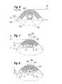
- Figure 6shows the cross-section of a typical drainage tube 500 fixated on the sclera 502.
- a section of donor tissue or graft 504is secured over the tube 500 and under the conjunctiva C.
- the graft 504helps distribute contact forces along the generatrix of the tube 500, but movement from rubbing the eye sometimes erodes the sclera 502.
- the overall height H of the structurepresents an irritation to the patient.
- One solutionis to reduce the diameter of the tube 500, as mentioned above.
- the profile of the tubemay be modified to retain the fluid flow characteristics but lower its height.
- Figure 7shows an oval-shaped drainage tube 520 having a minor dimension A 1 and a major dimension B 1 .
- Two lumens 522, 524 separated by a bridge 526transmit the same volume of fluid as with a single circular lumen, but the overall height h of the structure is reduced.
- the lessened height hpresents a smaller physical bulge in the eye and consequent reduction in patient discomfort.
- the flatter profilereduces the likelihood of the tube 520 rolling upon the patient rubbing the spot on the eye.
- the bridge 526provides a structural stiffener to help prevent kinking of the tube as it bends into the inner chamber of the eye.
- a single oval-shaped lumenmay be used as long as the structure resists kinking.
- the minor dimension A 1is 0.4 mm
- the major dimension B 1is 0.7 mm
- the diameter of the two identical lumens 522, 524is 0.2 mm.
- Figure 8depicts an alternative oval-shaped drainage tube 540 having a minor dimension A 2 and a major dimension B 2 .
- two lumens 542, 544 separated by a bridge 546transmit the same volume of fluid as with a single circular lumen, but again the overall height h of the structure is reduced.
- the oval shapeis modified so that the lateral edges are even further contoured to more comfortably fit inside the graft and conjunctiva. This contouring further reduces patient discomfort and the likelihood of movement of the tube.
- the minor dimension A 2is 0.35 mm
- the major dimension B 2is 0.8 mm
- the height C of the two identical lumens 522, 524is 0.15 mm
- the width D of the two lumensis 0.25 mm.
- a groovemay be formed in the sclera to receive the tube.
- Figures 9 and 10illustrate an exemplary tool 600 for forming such a groove.
- the tool 600includes a blade 602 having a two-dimensional leading edge, in this case rectangular, though other shapes such as V-shaped or semicircular may be suitable.
- Two wings 604flank the blade 602, and the tool further includes a pair of manipulators 606 connected to a handle 608.
- Figure 10shows the tool 600 in the process of forming a trough or groove 610 in the sclera by removing a section of tissue 612.
- the depth of the blade 602is controlled by the relative position of the wings 604.
- the wings 604are rounded and formed of a soft or lubricious material to reduce any incident damage to the sclera.
- the drainage tubemay be placed therein and covered with the aforementioned tissue graft and conjunctiva C.
- a conventional drainage tube 500is seen in a groove 610 in Figure 11A .
- the strip of sclera tissue 612 cut during the formation of the groove 610may be used for the tissue graft.
- the overall height his reduced from the conventional arrangement seen in Figure 6 .
- Figures 11B and 11Cshow placement of the modified tubes 520 and 540 in grooves 610, which even further reduces the overall height of the assembly.
- the present applicationalso presents a solution for the initial period before adequate formation of the bleb. That is, for a period of between 1-2 months while the scar tissue heals around the implant, aqueous should not flow freely through the drainage tube for risk of inducing a harmful low IOP. Consequently, the present application contemplates a flow restrictor for use in non-valved glaucoma drainage devices in order to control aqueous flow directly after implantation, but that also immediately lowers the intraocular pressure (IOP).
- IOPintraocular pressure
- the flow restrictors described hereinare positioned in the drainage tube between the scleral plate and the bend in the drainage tube which enters an incision toward the eye chamber.
- the flow restrictormay be held in position by an absorbable suture tied around the tube during the first weeks of the post-operative period until the bleb around the plate is formed, or by an internal feature in the tube as shown. Early aqueous flow is controlled by the flow restrictor until the flow restrictor dissolves, after which the bleb controls the aqueous flow.
- the presence of the tubular flow restrictor within the drainage tubealso helps reduce instances of tube fracture which may occur if the surgeon applies a suture ligature.
- flow restrictors described hereinhave an outer diameter that fits the inner tube diameter of the glaucoma shunt (e.g., 0.3mm for the current Baerveldt shunt).
- the flow restrictorsare also desirably placed an appropriate distance between the plate and the bend in the drainage tube that descends into the eye (typically a length between about 1-4 mm).
- the most straight forward geometry for the flow restrictoris based on a tube, though other geometrical configurations are possible (also multiple holes) as long as the desired facility is obtained to flow aqueous so that the desired IOP level is reached.
- Figures 12A and 12Bare longitudinal sectional views of an exemplary flow restrictor 700 positioned within a first lumen 702 of a shunt drainage tube 704.
- the restrictor 700has a tubular configuration with a cylindrical exterior shape that fits against a shoulder between the first lumen 702 and a second, smaller lumen 706 in the tube 704. The step between the two lumens prevents the flow restrictor 700 from entering the chamber of the eye.
- the restrictor 700defines a relatively small throughbore 708 that initially permits a small flow of aqueous therethough, thus relieving some of the built up IOP. Over time, as indicated in Figure 12B and Figure 13A , the material of the flow restrictor 700 dissolves in the aqueous and a larger throughbore 710 forms. The flow gradually increases to a magnitude at which the downstream bleb functions as the pressure regulator.
- the flow restrictor 70could be made of existing available resorbable suture material. A hole of 0.02 mm in a length of suture having a 0.3 mm outer diameter could be laser manufactured or extruded. After bleb formation the suture holding the flow restrictor could be released, and the flow restrictor will flow towards the bleb.
- the total facility (conductance) of aqueous flow in the human eyeis considered to be 0.3 ⁇ l/minute per mmHg.
- the desired resistance for the flow restrictoris the inverse of the facility, or 3.33 mmHg per ⁇ l/minute. This value could also be obtained from the pressure difference between the eye chamber (normal value is 15-16 mmHg) and the epi sclera (9-10mmHg), divided by the aqueous flow ranging from 1.5 to 4.0 ⁇ l/minute.
- the radius rangeis only up to about 5 ⁇ m which is close to manufacturing tolerances.
- the typical geometry of a cylindrical two millimeters long flow restrictoris an outer diameter almost equal to inner diameter of the tube of the glaucoma shunt involved (0.3mm is applicable for the Baerveldt shunt), and an inner diameter of 0.02mm.
- Figures 13B-13Care cross-sectional views of alternative flow restrictors within shunt drainage tubes.
- Figure 13Bshows a cylindrical flow restrictor 720 having a keyhole-shaped throughbore 722. The resulting eroded shape 724 is shown to the right. Any non-symmetric or otherwise non-circular throughbore could be used if it adequately prevented full flow for the desired time frame, after which it no longer presented an appreciable drag on flow.
- Figure 13Cshows a flow restrictor 730 with three spaced triangular notches 732 on its periphery. Aqueous eventually dissolves the material to leave remnants 734, or none at all if the flow washes them downstream.
- FIGS 14A and 14Bare cross-sectional view of the human eye in which a glaucoma shunt 800 constructed in accordance with the present application is positioned.
- a curved pliable plate 802also referred to as a pliable seton, conforms to the sclera 804 and connects to a discharge or drainage tube 806 that extends into the anterior chamber 810 of the eye.
- a drainage bleb 812eventually surrounds the plate 802.
- the tube 806 and plate 802are designed to initially restrict fluid flow after implant, but gradually permit flow. This is done using a movable flow restrictor 820 that extends into a lumen of the drainage tube 806.
- the flow restrictor 820comprises an elongated thin filament, tube or flexible rod that desirably conforms closely to the inner diameter of the drainage tube 806, permitting some flow but substantially occluding maximum flow therethrough.
- the length of the flow restrictor 820is such that a distal portion 822 extends a predetermined distance into the tube 806 and a proximal portion 824 projects upward through the bleb 812.
- the flow restrictor 820includes a through lumen or longitudinal flow channel in at least the distal portion 822, but such a channel does not extend completely along the proximal portion 824 so that a flow passage past the bleb 812 is not created.
- the proximal portion 824 extending past the bleb 812provides a convenient length that can be grabbed and manipulated post-op.
- the proximal portion 824projects through the covering tissue (conjunctiva, muscular capsule) far enough to be accessible by a surgeon with minimally-invasive surgery.
- the configuration of the flow restrictor 820is such that it modifies the pressure gradient and flow through the drainage tube 806 depending on how much of the length of the flow restrictor is in the tube.
- the flow restrictor 820may comprises a tube thinner than the inner lumen of the drainage tube 806 and having a lumen that permits some flow therethrough.
- An open side channel or a porous side wallpermits lateral flow out of the proximal portion 824 of the flow restrictor 820 that is not within the drainage tube 806, while the distal portion 822 in the drainage tube limits flow. Therefore, the greater the distal portion 822 in the drainage tube, the more flow is limited.
- Figures 15A-15Fare perspective views of several alternative flow restrictors having position indicators thereon.
- Figure 15Ashows a constant diameter tube 830 having a series of length indicator bands 832 spaced apart at regular increments along its exterior.
- the indicator bands 832may be printed on the tube 830 or formed by physical indents.
- the bands 832may be formed by a laser, for example.
- the bandsmay be color coded to convey relative position information, but in any event serve to communicate the relative position change of the flow restrictor tube 830 in the drainage tube 806. That is, the flow restrictor tube 830 may be initially placed at a predetermined distance into the drainage tube 806, and then moved farther in or out depending on the measured IOP.
- means for visualizing at least the tip of the restrictor within the tube/shuntis provided.
- a colored tip visible through the clear/opaque tube/shuntmay be utilized, such as fluorescent material when seen under blue or violet light.
- FIGS 15B and 15Cshow additional tubular flow restrictors 840, 850 that have exterior markings 842, 852, respectively.
- the markings 842provide numerical indicators of the position of the tube 840, while the marking 852 provides a relative position indicator in the form of a gradually increasing slider-like icon.
- Both tubular flow restrictors 840, 850function in essentially the same manner as the flow restrictor 830.
- Figure 15Dis slightly different, in that a tubular flow restrictor 860 includes a plurality of side holes or ports 862 along its length. These ports 862 permit flow laterally out of the lumen of the flow restrictor 860 in the proximal portion that is outside of the drainage tube 806.
- Figure 15Eshows a still further flow restrictor 870 that has a C-shaped cross-section including an open longitudinal channel 872 along its length. As with the side ports, the channel 872 permits flow past the restrictor 870 in the proximal portion that is outside of the drainage tube 806.
- FIG. 15FAnother controllable flow restrictor solution shown in Figure 15F is a tapered solid obturator 880 with a narrow distal end 882 that gradually widens in a proximal direction. As the tapered obturator 880 is pulled from within the drainage tube 806 the spacing therebetween gradually increases, thus permitting more flow through the drainage tube.
- the various flow restrictors in Figures 14-15are desirably non-dissolvable, but may also be resorbable as desired.
- the flow restrictoris inserted into the drainage tube prior to implant, most likely during assembly.
- the surgeonimplants the glaucoma shunt and positions the drainage tube in the eye.
- the flow restrictormay be adjusted relative to the tube to increase or decrease flow. This may be done in several stages, which is facilitated if the flow restrictor extends a distance beyond the shunt plate.
- the surgeonapplies a ligating suture to secure the drainage tube, which also secures the flow restrictor therein.
- One benefit of having the flow restrictor in the drainage tubeis to prevent common complications like tube breakage when surgeons apply ligature sutures.
- a ligature suture around a tube with a flow restrictor insidewill be less likely to collapse, kink or cut through the drainage tube.
- the fixating suture around the tubeis removed, or dissolves, which releases constriction on the flow restrictor.
- the flow restrictorwhich in this embodiment is 1-3 mm in length, may then migrate from fluid pressure out of the drainage tube, ending up within the bleb, which is harmless.
- a short length of polypropylene suture having a through lumenmay be suitable for such a flow restrictor.
- a mini pressure sensoronto the glaucoma shunt, with which the IOP can be rapidly measured during implant.
- a mini pressure sensormay be provided in a graft that fixes the drainage tube to the outside of the sclera, and have a probe that extends into the tube to measure pressure therein.
- the flow restrictormay be installed at a presumed proper length within the drainage tube based on an initial estimation of flow volume versus flow restrictor position. The flow restrictor will be set at the default position and then adjusted after equilibrium pressure is established and measured (out for lower pressure, in for greater pressure).
- NXPa former division of the Dutch firm Philips, is able to produce mini pressure sensors having dimensions of approximately 80x150x150 microns that may be suitable.
- Research into intraocular pressure sensinghas been done by Kakaday, et al. in "Advances in Telemetric Continuous Intraocular Pressure Assessment," British Journal of Ophthalmology 2009; 93:992-996 , and by Mokwa in "Ophthalmic Implants," 2003 IEEE Publication, 980-986, Institute of Materials in Electrical Engineering, RWTH Aachen Univ., Aachen, Germany , the disclosures of which are incorporated by reference herein.
- Alternatives for fixating the flow restrictor within the drainage tubeinclude applying an exterior resorbable suture around the tube until it is itself absorbed and stops exerting pressure on the flow restrictor from outside the tube.
- the absorbable suturescan be assembled during manufacturing.
- the forcecan be applied by a flow restrictor of a polymeric biocompatible memory material that expands when heated to 40°C, e.g. Such an active flow restrictor may be caused to break up or otherwise flow through upon exposure to laser light post-surgery.
- Another aspect of the present application that helps prevent endophthalmitis, or an inflammation of the inner eye,is to coat the various implant surfaces with an anti-bacterial coating or agent.
- surfaces on the pliable plate 40 or drainage tube 46 shown in Figures 1-4may be covered with an anti-bacterial.
- the inner lumen of any of the drainage tubes described hereinis coated with an anti-bacterial to ensure exposure of the fluid passing therethrough.
- the bioresorbable flow restrictors see in Figures 12-13may include an anti-bacterial component which elutes as the device dissolves.
- the movable flow restrictors seen in Figures 14-15are good candidates to have an anti-bacterial coating.
- Each of these deviceshas direct contact with the fluid that passes to and from the inner eye, and is thus optimally positioned to effect a reduction in infection during the early post-op stages of the procedure.
- an anti-microbial coatingis most beneficial begins immediately post-op and extends at least 2 weeks, and potentially up to 2 months.
- a blebforms and effectively closes the fluid system from outside bacteria.
- the amount of time it takes for the bleb to formdepends on a number of factors, including the age and health of the patient, and the use of topical medications such as antibiotics or steroids are administered.
- an anti-microbial coating that lasts for about 2 monthswill provide the intended protection.
- a coating on a flexible silicone or other polymer shuntconforms to uneven surfaces and reduces irritation as compared to a metallic shunt and may improve adhesion to the surrounding tissues.
- a number of suitable anti-bacterial coatingsare available, including those that release silver ions (Ag+) or silver nano particles.
- One supplier of such coatingsis Bio-Gate AG of Nurnberg, Germany, which markets antimicrobial additives and antimicrobial materials that can prevent the growth of undesired bacteria and other micro-organisms.
- the surfacesare coated with microsized or nanosized silver particles to offer protection against bacteria, fungi, and other unwanted germs.
- U.S. Patent Nos. 6,984,392 and 7,476,698 assigned to Bio Gate AGdescribes certain formulations of anti-microbial coatings.
- anti-microbial coatingswhich may be suitable, including Boston Scientific Scimed, Inc. of Maple Grove, MN in U.S. Patent No. 7,635,358 and 1-Flow Corp. of Lake Forest, CA in U.S. Patent No. 7,547,302 , whose disclosures are expressly incorporated herein by reference.
- the Boston Scientific patentproposes a substrate formed from the anti-microbial agent such as an iodine-polycarbonate material.
- the I-Flow patentdiscloses anti-microbial layers or materials configured to provide the sustained release of anti-microbial agents.
- the anti-microbial layer or materialmay be a heavy metal such as gold, platinum, silver, zinc or copper, including heavy metal ions.
- Other anti-microbial substancesmay also be used such as antibiotics or germicidal chemicals. Of course, these are just a few examples, and numerous other suitable anti-microbial coatings or agents may be used in the present application.
- anti-microbial coatings or agentsare desirable not just for the glaucoma shunts described herein, but also for other glaucoma shunts for relieving intraocular pressure.
- devices that create a direct passage from the anterior chamber to the conjunctivasuch as the Ex-PRESS Mini Glaucoma Shunt from Optonol of Neve Ilan, Israel, may benefit from an antimicrobial coating to help prevent infection post-op.
- Another type of device that would likely be improved with an anti-microbial coatingis a micro filter on the outer end of a drainage tube inserted into the anterior chamber, such as that disclosed in U.S. Patent No. 7,641,627 to Camras .
- SOLX® Gold Shuntdevices that create a bridge between the supraciliary space and the anterior chamber, such as the SOLX® Gold Shunt, may be improved with the addition of an anti-microbial coating.
- the SOLX devicecan be seen in U.S. Patent No. 7,207,965 .
- a desirable glaucoma shuntmay have a pliable plate with a decreased surface area in accordance with the principles described above and at least 8 fenestration holes, microtexturing on an outer or inner face and also on the elastomeric drainage tube, an inner tube lumen having a radius of less than 50 microns, a flow restrictor that either dissolves or is movable in the drainage tube, and an anti-microbial coating on at least the lumen of the drainage tube.
- the improved glaucoma shuntswill produce a lower bleb height, which reduces any detrimental interaction with eye muscle coordination.
- the improved shuntwill also effectively regulate IOP, and prevent endophthalmitis.
Landscapes
- Health & Medical Sciences (AREA)
- Ophthalmology & Optometry (AREA)
- Heart & Thoracic Surgery (AREA)
- Surgery (AREA)
- Engineering & Computer Science (AREA)
- Biomedical Technology (AREA)
- Nuclear Medicine, Radiotherapy & Molecular Imaging (AREA)
- Vascular Medicine (AREA)
- Life Sciences & Earth Sciences (AREA)
- Animal Behavior & Ethology (AREA)
- General Health & Medical Sciences (AREA)
- Public Health (AREA)
- Veterinary Medicine (AREA)
- Prostheses (AREA)
- External Artificial Organs (AREA)
Abstract
Description
- The present application claims priority under 35 U.S.C. §119(e) to Provisional Application No.
61/163,862, filed on March 26,2009 - The present invention relates to treatments for glaucoma in the eye and, more particularly, to glaucoma shunts and methods of use for draining fluid from the eye at a controlled rate.
- Intraocular pressure in the eye is maintained by the formation and drainage of aqueous humor, a clear, colorless fluid that fills the anterior and posterior chambers of the eye. Aqueous humor normally flows from the anterior chamber of the eye out through an aqueous outflow channel at a rate of 2 to 3 microliters per minute.
- Glaucoma is a progressive disease of the eye characterized by a gradual increase of intraocular pressure (IOP). This increase in pressure is most commonly caused by stenosis or blockage of the aqueous outflow channel, resulting in excessive buildup of aqueous fluid within the eye. Other causes include increase in venous pressure outside the eye which is reflected back through the aqueous drainage channels and increased production of aqueous humor. In a "normal" eye, IOP ranges from 8 to 21 mm mercury. In an eye with glaucoma, IOP can range between normal pressures up to as much as 50 mm mercury. This increase in IOP produces gradual and permanent loss of vision in the afflicted eye.
- Existing corrective methods for the treatment of glaucoma include drugs, surgery, and implants. Pharmacological treatment is prohibitively expensive to a large majority of glaucoma patients. In addition, many people afflicted with the disease live in remote or undeveloped remote areas where the drugs are not readily accessible. The drugs used in the treatment, in particular steroids, often have undesirable side effects and many of the long-term effects resulting from prolonged use are not yet known. Additionally, patient compliance is an issue and, for example, patients often forget their medication.
- Surgical procedures have been developed in an effort to treat victims of glaucoma. An iridectomy, removal of a portion of the iris, is often used in angle-closure glaucoma wherein there is an occlusion of the trabecular meshwork by iris contact. Removal of a piece of the iris then gives the aqueous humor free passage from the posterior to the anterior chambers in the eye. A trabeculotomy, opening the inner wall of Schlemm's canal, is often performed in cases of developmental or juvenile glaucoma so as to increase the outflow of the aqueous humor, thereby decreasing IOP. In adults, a trabeculectomy shunts fluid through a trapdoor flap in the eye that performs a valve-like function for the first few weeks after surgery.
- While often successful, these surgical techniques possess inherent risks associated with invasive surgery on an already afflicted or compromised eye. Furthermore, the tissue of the eye can scar over this small area and the eye reverts to the pre-operative condition, thereby necessitating the need for further treatment.
- Ocular implants are often used in long-term glaucoma treatment. One early implant is described in the paper entitled "Use of Molteno Implants to Treat Secondary Glaucoma" by A. C. B. Molteno and published by Grune & Stratton, Ltd, 1986, pp 211-238. The implant was a small circular plate with a rigid translimbal drainage tube attached thereto. The plate was 8.5 mm in diameter and formed a surface area of about 100 mm2. This early Molteno implant was sutured to the sclera in the anterior segment of the eye at the limbus and the drainage tube was inserted into the anterior chamber of the eye. Once implanted, the body forms scar tissue around this plate. Fluid causes the tissues above the plate to lift and form a bleb into which aqueous humor flows from the anterior chamber via the drainage tube. A bleb is a fluid filled space surrounded by scar tissue, somewhat akin to a blister. The fluid within the bleb then flows through the scar tissue, at a rate which desirably regulates IOP.
- Many problems occurred with the early Molteno device. The bleb that formed on the sclera was elevated, which resulted in Dellen formation (sterile corneal ulcers). The implant sometimes had to be removed in another surgery to cure the ulcers. Further, this early device often did not reduce the IOP enough to treat the glaucoma without the use of additional medications.
- Dr. Molteno redesigned his implant for insertion into the posterior segment of the eye to avoid the problems with his early anterior device, as disclosed in
U.S. Pat. No. 4,457,757 entitled "Device for Draining Aqueous Humor." This implant is commercially available as the Molteno® Seton Implant and is also referred to as the long tube Molteno implant. The implant comprises a flexible drainage tube connected to one or more rigid plate reservoirs. The plates are shaped to conform to the curvature of the eye. The long tube Molteno implant is disadvantageous as the plates are formed of a rigid plastic which makes insertion beneath the eye tissue difficult and time-consuming. The reservoir plate is placed under Tenon's capsule in the posterior segment of the eye and sutured to the sclera. The drainage tube is implanted into the anterior chamber through a scleral incision. - After a glaucoma implant is attached, IOP tends to fall as aqueous fluid flows immediately through the drainage tube. An open drainage tube may release too much of the fluid too fast, which is detrimental to the eye. It is not until 2-6 weeks later that the bleb forms around the plate to sufficiently regulate the fluid flow. Some prior devices have therefore incorporated valves in the fluid drain path designed to function for a limited time until the bleb forms. However, such valved devices sometimes clog later, requiring another surgery.
- More recently,
U.S. Patent Nos. 5,476,445 and6,050,970 to Dr. George Baerveldt, et al. disclose glaucoma implants or shunts featuring a flexible plate that attaches to the sclera and a drainage tube positioned for insertion into the anterior chamber of the eye. A bleb forms around the plate and fluid drains into and out of the bleb to regulate IOP. This type of shunt is sold under the tradename Baerveldt® BG Series of glaucoma implants by Abbott Medical Optics (AMO) of Santa Ana, CA. The Baerveldt® device has an open tube with no flow restricting elements. Temporary sutures are used to restrict fluid flow for a predetermined period after which the bleb forms and fluid drainage is properly regulated. The temporary sutures are either biodegradable or removed in a separate procedure. This method works well, but the timing of suture dissolution is necessarily inexact, and a second procedure undesirable. - The Baerveldt® shunts also include four fenestrations (perforations or holes) through the plate to promote fibrous adhesion, which may reduce bleb height. Though a bleb is thought to have a beneficial function in regulating aqueous humor diffusion, too large of a bleb may cause the patient some pain or may be aesthetically unacceptable. Some doctors even prefer to use anti-proliferatives such as mitomycin C or 5-FU at the time of surgery to prevent formation of the fibrous bleb. Another potential complication is endophthalmitis, or an inflammation of the internal tissue of the eye. This complication may occur in any intraocular surgery, with possible loss of vision and the eye itself. Infectious etiology is the most common cause, and various bacteria and fungi have been isolated as the cause of the endophthalmitis. The risk of infection is more pronounced early in a glaucoma shunt procedure when a passage to the interior of the eye is created and fluid flows therethrough. Later, a bleb forms which acts as a filter to prevent microorganisms such as bacteria from entering the eye.
- Despite accepted treatments for regulation of intraocular pressure using glaucoma shunts, there is a need for an implant that better manages 1) the configuration of the bleb and attendant aqueous flow performance,and 2) flow performance directly after implantation and before bleb formation.
- The present application provides various solutions for improving glaucoma shunts and reducing post-op complications. In a preferred embodiment, a glaucoma shunt having a pliable plate attached to the sclera and a drainage tube that extends into the inner eye causes a bleb to form around the plate which effectively regulates intraocular pressure (IOP). The pliable plate has a reduced size and may be microtextured in particular areas to control cell adhesion thereto. A flow restrictor within the drainage tube helps prevent excessive pressure buildup or dropoff immediately post-op, and an anti-microbial coating reduces the chance of infection.
- In accordance with one aspect, an implantable glaucoma shunt for treating glaucoma in an eye includes a plate adapted to be positioned on the sclera, the plate having microtexturing on at least an outer or an inner face comprising an average peak-to-valley depth normal to the outer face of between about 0.5 - 10 microns. An elastomeric drainage tube has an outflow end that connects to the plate, opening at the outer face thereof, and an inflow end extending away from the plate. The drainage tube has an open lumen and a length sufficient to extend into the anterior chamber of the eye. The glaucoma shunt microtexturing may comprise surface features that collectively have an average peak-to-valley depth, an average width perpendicular to the depth, and an average pitch separating individual features, all of which are between about 0.5 - 10 microns. For instance, the average peak-to-valley depth may be about 0.5 microns and the average pitch separating individual features about 4 microns. In one embodiment, the microtexturing comprises uniform, regular shaped elements with sharp corners, or the microtexturing elements may be selected from the group consisting of grooves, ridges, wells, and pillars.
- In a preferred embodiment, the plate has a concave inner face and a convex outer face, and further includes a plurality of fenestrations extending therethrough from the inner face to the outer face. Both the inner and outer faces may have the microtexturing, which may be provided in different patterns on the inner and outer faces. In one version, the microtexturing encircles the fenestrations within radii of about 1 mm to about 5 mm. The microtexturing may also be located on the periphery of the outer face of the plate, or the microtexturing may be only on the periphery of the outer face of the plate. Desirably, the microtexturing promotes cell adhesion with adjacent tissue and is located in a pattern that channels allowing fluid flow between regions with microtexturing. The plate may further include a chemical coating to promote cellular adhesion, which may be selected from the group consisting of polyethylene glycol (PEG), heparin, nano-coatings of titanium selectively sputter-coated, silicone oxide, and silicone oxide with polyethylene glycol. In another embodiment, the microtexturing is further provided on the exterior of the elastomeric drainage tube.
- Another aspect of the present invention is an implantable glaucoma shunt for treating glaucoma in an eye which has a plate adapted to be positioned on the sclera having on at least an outer face cell adhesion regions with increased propensity for cell adhesion alternating with surface regions that have relatively lower propensity for cell adhesion. An elastomeric drainage tube has an outflow end that connects to the plate, opening at the outer face thereof, and an inflow end extending away from the plate. The drainage tube has an open lumen and a length sufficient to extend into the anterior chamber of the eye. The surface regions may form interconnected channels that isolate at least one of the cell adhesion regions from the other cell adhesion regions. Desirably, the cell adhesion regions comprise regions of texturing, and in particular may comprise microtexturing having an average peak-to-valley depth normal to the outer face of between about 0.5 - 10 microns. The microtexturing may comprise uniform, regular shaped elements with sharp corners. Alternatively, the cell adhesion regions comprise regions of chemical coating.
- Another implantable glaucoma shunt for treating glaucoma in an eye disclosed herein features a plate adapted to be positioned on the sclera, and an elastomeric drainage tube. The tube has an outflow end connected to the plate, opening at the outer face thereof, and an inflow end extending away from the plate. The drainage tube further has an open lumen and a length sufficient to extend into the anterior chamber of the eye. The exterior of the drainage tube near the outflow end has microtexturing thereon with an average peak-to-valley depth normal to the exterior of between about 0.5-10 microns.
- A still further implantable glaucoma shunt for treating glaucoma in an eye of the present application, comprises a plate adapted to be positioned on the sclera and having an effective surface area Aeff of 250 mm2 or less. The plate also has at least 8 fenestrations extending between an outer face and an inner face. An elastomeric drainage tube has an outflow end that connects to the plate, opening at the outer face thereof, and an inflow end extending away from the plate. The drainage tube has an open lumen and a length sufficient to extend into the anterior chamber of the eye. The effective surface area Aeff of the plate may be determined by the formula A + G, where:
- A = the tissue surface area surrounding the plate within its periphery, and
- G = a reduction in plate effective surface area determined by:

and where:- M = number of fenestration holes,
- R = radius of fenestration holes, and
- B = bleb height.
- Currently, a good estimation is that the tissue surface area A surrounding the plate within its periphery should be around 200-400 mm2 (based on the satisfactory clinical use of the Baerveldt® BG Series shunt having plate areas of 250mm2 and 350 mm2). Also, a maximum reduction in plate surface will be reached if radius of fenestration hole is identical to the bleb height.
- In accordance with a still further aspect of the application, an implantable glaucoma shunt for treating glaucoma in an eye includes a plate adapted to be positioned on the sclera, and an elastomeric drainage tube having an outflow end connected to the plate, opening at the outer face thereof, and an inflow end extending away from the plate. The drainage tube has an open lumen and a length sufficient to extend into the anterior chamber of the eye, the inner lumen of the tube having a radius of less than 50 microns. The inner tube lumen radius is desirably less than 50 microns and greater than or equal to a magnitude determined by the following formula:

where: - average aqueous resistance R = 3.333 mmHg/microliter/minute,
- 1 mmHg = 133.3 Pa (kgm/s2),
- 1 microliter/minute = 1.667 × 10⁻¹¹ m3/s,
- L = length of tube (mm),
- average aqueous resistance R = 2.666 × 10¹³ kg/s2, and
- dynamic viscosity η = 7.50 × 10⁻⁴ kg/sm.
- A still further implantable glaucoma shunt for treating glaucoma in an eye described herein includes a plate adapted to be positioned on the sclera, and an elastomeric drainage tube. The tube has an outflow end connected to the plate and opens at the outer face thereof. An inflow end of the tube extends away from the plate, and the tube has an open lumen and a length sufficient to extend into the anterior chamber of the eye. Furthermore, the tube has a non-circular radial outer cross-section. For instance, the radial outer cross-section of the tube may be oval.
- Another aspect of the application is an implantable glaucoma shunt for treating glaucoma in an eye including a plate adapted to be positioned on the sclera, and an elastomeric drainage tube having an outflow end connected to the plate and opening at the outer face thereof. An inflow end of the tube extends away from the plate, and the tube has a lumen and a length sufficient to extend into the anterior chamber of the eye. A flow restrictor positioned within the drainage tube has an open throughbore smaller than the lumen. The flow restrictor may be made of a material that may dissolve in aqueous fluid, or may be a non-dissolving material. In the latter embodiment, a short length of flow restrictor may be installed in the drainage tube and temporarily held in place by a fixation ligature. After the ligature resorbs or is removed, the flow restrictor migrates from fluid flow out of the tube and into the bleb.
- A method of implanting a glaucoma shunt for treating glaucoma in an eye is also disclosed, and includes first providing a glaucoma shunt having a plate adapted to be positioned on the sclera and an elastomeric drainage tube having an outflow end connected to the plate and opening at the outer face thereof. The drainage tube also has an inflow end extending away from the plate, and a lumen and a length sufficient to extend into the anterior chamber of the eye. The method involves forming a groove in the sclera, attaching the shunt plate to the sclera, inserting the inflow end of the drainage tube through an incision into the eye, and positioning and securing a mid-portion of the drainage tube in the groove.
- Features and advantages of the present invention will become appreciated as the same become better understood with reference to the specification, claims, and appended drawings wherein:
Figure 1 is a cross-sectional view of the human eye which illustrates the glaucoma shunt of the present application after implant;Figure 2 is a cross-sectional view of the glaucoma shunt ofFigure 1 ;Figure 3 is a perspective view of an exemplary glaucoma shunt disclosed herein having a plurality of fenestration holes and a raised peripheral ridge;Figure 4 is an outer face plan view of the glaucoma shunt ofFigure 3 ;Figures 5A-5D are outer face plan views of alternative glaucoma shunts disclosed herein having regions of increased cell adhesion, e.g., texturing, alternating with smooth surface regions;Figure 6 is a cross-sectional view of a drainage tube used with glaucoma shunts of the prior art;Figures 7 and 8 are cross-sectional views of exemplary drainage tubes for use with various glaucoma shunts disclosed herein;Figure 9 is a perspective view of a tool that may be used to create a scleral groove for receiving glaucoma shunt drainage tubes;Figure 10 is a perspective view of use of the tool ofFigure 9 ;Figures 11A-11C are cross-sectional views of exemplary scleral grooves with the drainage tubes ofFigures 6-8 , respectively, positioned therein and a flap of tissue or other material thereover to fix the tubes within the grooves;Figures 12A and 12B are longitudinal sectional views of an exemplary flow restrictor within a shunt drainage tube;Figures 13A-13C are cross-sectional views of alternative flow restrictors within shunt drainage tubes;Figures 14A and 14B are cross-sectional view of the human eye showing an alternative flow restrictor within a glaucoma shunt drainage tube; andFigures 15A-15F are perspective views of several alternative flow restrictors having position indicators thereon.Figure 1 illustrates aglaucoma shunt 10 constructed in accordance with the present application positioned within the tissue of an eye 12 (looking upward relative to the page). The relevant structures of theeye 12 will be described briefly below to provide background for the anatomical terms incorporated herein, however, it should be realized that a number of anatomical details have been omitted for clarity of understanding. The tough outer membrane known as the sclera 14 covers all of theeye 12 except that portion covered by thecornea 16, the thin, transparent membrane which enables light to enter thepupil 18 defined by the iris aperture in front of thelens 20. Thecornea 16 merges into the sclera 14 at a juncture referred to as thelimbus 22. Theciliary body 26 begins near thelimbus 22 and extends along the interior of thesclera 14.- It is well-known that aqueous humor is produced by the
ciliary body 26 and reaches theanterior chamber 30 formed between theiris 18 and thecornea 16 through the pupil. In a normal eye, most of the aqueous humor is removed through thetrabecular meshwork 32, though there is also minor uveoscleral outflow. From there the aqueous humor passes through Schlemm'scanal 36 and through veins which merge with blood-carrying veins and into venous circulation. Intraocular pressure is maintained in theeye 12 by the intricate balance of secretion and absorption or outflow of the aqueous humor in the manner described above. The condition of glaucoma results from excessive buildup of aqueous fluid in theanterior chamber 30 which produces an increase in intraocular pressure. The present invention is designed for treatment of glaucoma by facilitating the outflow of the aqueous humor from theanterior chamber 30 of theeye 12. - With reference to
Figures 2-4 as well asFigure 1 , theglaucoma shunt 10 comprises apliable plate 40, also referred to as a pliable seton in the ophthalmic field, having oppositely disposed convex outer 42 and concave inner 44 faces. The curvature of theplate 40 conforms to thesclera 14 and connects to a discharge ordrainage tube 46 that extends into theanterior chamber 30 of theeye 12. - The
plate 40 is preferably formed of silicone elastomer, such as SILASTIC®, Medical Grade Q7-4765, 65 Shore A, manufactured by Dow Corning Corporation of Midland, MI or Nusil Corp. of Santa Barbara, CA, although other silicone elastomers in the range of 40-85 Shore A and having good elastic memory are also suitable. The silicone elastomer may be mixed or doped with a radiopaque material, such as Barium Sulfate, so that the implant is visible in X-rays procedures. - With reference now to
Figures 3 and 4 , elements of theglaucoma shunt 10 can be more clearly described. Thedrainage tube 46 comprises anoutflow end 50 and aninflow end 52, wherein theoutflow end 50 attaches to theplate 40 and opens to theouter face 42. Theplate 40 has a generally spherical curvature with an elliptical perimeter looking down or in plan view, as inFigure 4 . The surface area of theplate 40 is preferably in the range of approximately 100 to 600 mm2 depending on glaucoma conditions and the radius of curvature of theplate 40 is preferably 12-14 mm. An optional raisedborder 54 projects outward from the outerconvex face 42 and extends around the perimetric edge of theplate 40. Theinner face 44 of theplate 40 curves to conform to the curvature of theeye 12, specifically the curvature of thesclera 14, and theborder 54 follows that curvature. - The thickness of the
plate 40 in combination with the raisedborder 54 is desirably about 150-200% the thickness of the plate itself. Theperipheral border 54 provides rigidity to theplate 40 to assist a surgeon to manipulate it through an incision and into proper placement. Moreover, the structural strength provided by theperipheral border 54 permits the central portion of theplate 40 to be made thinner, potentially 0.2 mm thinner than previous designs, or 10-50% thinner in relative terms. Athinner plate 40 forms a thinner bleb, which assists in the eventual pressure regulating function of theshunt 10. That is, a thicker bleb wall has a higher IOP in the eye. Conversely, reducing the bleb thickness increases outflow, which in turn decreases the ocular IOP. The precisely engineeredplate 10 then governs the increased outflow of aqueous fluid. - The
drainage tube 46 connects to theplate 40 with adhesive, such as Clear Silicone Rubber Adhesive RTV-118 manufactured by General Electric Silicone Products of Waterford, N.Y., via a small hole formed in aridge 56. In the illustrated embodiment, theridge 56 comprises a segment of the raisedborder 54, though in the absence of the border theridge 56 would have a width similar to the width of a tab orextension 58 described below. Theoutflow end 50 of thetube 46 opens to and thus drains to theouter face 42 of theplate 40, and into the shallow outer recess circumscribed by the raisedborder 54. - The
tab 58 of theshunt 10 formed adjacent theridge 56 extends from one long side of theplate 40 and includes two pairs of suture holes 60, 62. Theextension 58 is desirably larger in size than previous such tabs to facilitate implant. That is, theplate 40 can be positioned relatively far back around theeye 12 with the suture holes 60, 62 on theextension 58 plainly visible and accessible. In a preferred embodiment, theplate 40 attaches to the sclera such that theridge 56, and thus theoutflow end 50 of thedrainage tube 46, is located between about 8-12 mm posteriorly from thelimbus 22. To permit this desirable positioning, theextension 58 has a width of about 4-12 mm and a length of about 2-10 mm. - The
plate 40 of the embodiment ofFigures 3-4 includes a series of holes orfenestrations 64 from theouter face 42 through to theinner face 44. Thefenestrations 64 permit aqueous fluid to pass from one side of theplate 40 to the other, and also tissue to form therethrough. In the illustrated embodiment there are sixteenfenestrations 64 spaced evenly around the periphery of theplate 40 just inside theborder 54, and four spaced generally evenly across the middle portion of the plate. Of course, other arrangements of fenestrations are contemplated, as described below with reference toFigures 5A and 5B . - The present invention can be implanted using known ophthalmological surgical techniques and, with reference to
Figure 1 , the surgical implant procedure will be briefly described. It should be understood that the following procedure may be used for any of the exemplary glaucoma shunts described herein. An initial incision is made in the Tenon'scapsule 70 parallel to thelimbus 22. Theplate 40 is inserted through the initial incision and positioned beneath the Tenon'scapsule 70 and a portion of the rectus muscle (not shown) or extending totally under one or more muscles, thus covering thesclera 14. Theplate 40 can be sutured to thesclera 14, or alternatively, to the rectus muscle if thesclera 14 is thinned by disease, with the suture holes 60, 62. Preferably, non-absorbable nylon sutures are used in the suture holes 60, 62 to secure theplate 40, such as 8-O nylon or polypropylene sutures. - The
drainage tube 46 tunnels out through thesclera 14 and thecornea 16 beneath Tenon'scapsule 70 and in through anincision 72 in the region of thelimbus 22 such that theinflow end 52 of thetube 46 extends into theanterior chamber 30 of theeye 12. A suture is typically used inside the tube as a stent to maintain stiffness during insertion. A dissolvable holding suture may be used to secure thetube 46 to the exterior of the sclera. A bend forms in thetube 46 just before entering theincision 72. The exposed portion of thedrainage tube 46 is then typically covered with a scleral reinforcing element (not shown), such as a connective tissue graft, i.e., a sclera graft, dura mater graft, fascia lata graft, or a graft formed from other biocompatible materials. - A
large drainage bleb 74 eventually surrounds theplate 40 and lifts the layer of Tenon'scapsule 70 above thesclera 14. Theplate 40 acts as a permanent bleb-controlling stent to inhibit the tendency of the body to heal itself which would eliminate the bleb. Fibrous rivets ofscar tissue 76 form on both sides of theplate 40, causing a low bleb. Thetube 46 andplate 40 are designed to initially restrict fluid flow after implant, but gradually permit flow. No valve is required. - One advantage of the presently disclosed glaucoma shunt is a reduced bleb size, both in footprint and height. Several structural features incorporated into the
glaucoma shunt 10 ofFigures 3 and 4 bring about a smaller bleb, and the use of selective areas of cell adhesion, described below, may be used in conjunction. One such feature is a decreased size of theplate 40 combined with more fenestrations 64. Another feature is a reducedheight ridge 56 for attaching theoutflow end 50 of thedrainage tube 46. Furthermore, a variety of novel drainage tube designs may lower complication rate with regard to tube mobility and tube erosion. Each of these features will be described below. - It should be understood that the diverse modifications to prior glaucoma shunts described herein may be independently implemented or combined with each other or other features. For instance, a smaller plate in conjunction with texturing on the plate and/or drainage tube may be utilized, or a lower plate ridge with a modified drainage tube. Moreover, known solutions such as flow restrictors or valves may be added. In short, it should be understood that various combinations of the solutions disclosed herein are within the scope of the invention.
- In terms of modifications to the size of the
plate 40, a decreased surface area in comparison with earlier plates is believed to reduce complications post surgery as well as ease implantation. The currently available glaucoma shunts have plates with a surface area of about 350 mm2. Commercially available plates have four fenestration holes, which has a proven track record. The overall surface area of the plate could be reduced by increasing the number of fenestrations from the current four. - Certain assumptions can be made with regard to glaucoma shunts in order to predict fluid flow and design a plate for controlled flow management. With reference again to
Figures 3 and 4 , the thickness of theplate 40 is preferably in the range of about 0.5 to 3.0 mm, and in an exemplary embodiment is about 0.94 mm. For the smallest thickness of 0.5 mm, an assumed bleb height is about double that, or 1 mm, though a range of between 0.5-1.0 mm is possible. That assumption stems from examination of images of implanted shunts fromLloyd, M.A., et al., "Intermediate-Term Results of a Randomized Clinical Trial of the 350-Versus the 500 mm2 Baerveldt Implant," Ophthalmology, August, 1994, 101(8). In accordance with the formula below, the reduction in plate area G will be maximized if the radius of fenestration hole is identical to the bleb height. - With reference to
Figure 1 , the flow of aqueous fluid around a functioning implanted shunt first emerges from theoutflow end 50 of thedrainage tube 46 on theouter face 42 of theplate 40. Aqueous fluid distributes within any spaces defined within thebleb 74 around theplate 40, including throughfenestrations 64 to the inner face. Gradually, aqueous diffuses through the surrounding tissue at a rate that is determined by the surface area of that tissue exposed to fluid. Consequently, the flow rate may be managed by designing a shunt to optimize the surface area of tissue exposed to fluid. It has been recognized that each plug of tissue that grows through thefenestrations 64 presents a cylindrical surface into which fluid also diffuses. Therefore, adding fenestrations 64 supplies that cylindrical tissue surface area in lieu of a circular area of tissue that would otherwise be exposed above the plate. That increase in tissue surface area can then be accounted for when designing the overall plate dimensions. The following equation represents the reduction in plate size G based on these observations:
where: - M = number of fenestration holes,
- R = radius of fenestration holes, and
- B = bleb height.
- Furthermore, a new effective plate surface area Aeff is equal to the reference surface area A (e.g., 350 mm2) plus G (which is negative):

- Another term that is useful is the ratio of the area of the fenestration holes divided by Aeff:

- To assure stability of the plate the ratio F should not be too high, and preferably is lower than 0.8.
- Finally, by setting the radius of the fenestration holes R to the bleb height B, which, again, maximizes the reduction in plate size G, the equation may be simplified to derive an optimum number of holes M for a given plate size reduction G, as follows:

- Several exemplary configurations are presented in the tables below.
Table I-A - Reduction in plate size, tissue reference surface area = 350 mm2 Plate thickness (mm) 0.5 0.5 1 1 Bleb height (mm) 1 1 2 2 Hole radius (mm) 1 1 2 2 A (mm2) 350 350 350 350 G (mm2) -101 -157 -101 -151 Aeff (mm2) 249 193 249 199 M 32 50 8 12 F 0.40 0.81 0.4 0.76 - These values are considered practical alternatives to reduce the overall plate size. Other values may be obtained by assuming a reference plate surface area A of between 200-400 mm2, as follows:
Table I-B - Reduction in plate size, tissue reference surface area = 250 mm2 Plate thickness (mm) 0.5 0.5 1 1 Bleb height (mm) 1 1 2 2 Hole radius (mm) 1 1 2 2 A (mm2) 250 250 250 250 G (mm2) -63 -110 -101 -113 Aeff (mm2) 187 140 149 137 M 20 35 8 9 F 0.34 0.79 0.67 0.83 Table I-C - Reduction in plate size, tissue reference surface area = 400 mm2 Plate thickness (mm) 0.5 0.5 1 1 Bleb height (mm) 1 1 2 2 Hole radius (mm) 1 1 2 2 A (mm2) 400 400 400 400 G (mm2) -101 -173 -101 -151 Aeff(mm2) 299 227 299 249 M 32 55 8 12 F 0.34 0.76 0.34 0.61 - Another way to reduce the size/height of the bleb is to reduce the size of the
ridge 56. Since theridge 56 acts as an anchor for thedrainage tube 46, reducing the size of the tube enables a reduction in the height of theridge 56. - The
drainage tube 46 is preferably about 5 mm to 35 mm in length, formed of SILASTIC®, Medical Grade RX-50, also available from Dow Corning Corporation or Nusil Corp. of Santa Barbara. In addition to Silicone, Teflon or polyurethane are also materials that may be suitable for thetube 46. Thetube 46 may be extremely thin so as to function as a temporary flow restrictor to stem the loss of aqueous fluid prior to proper formation of a bleb. - In determining the minimum size of the
drainage tube 46, the wall thickness should strike a balance between stiffness and flexibility. A minimum stiffness is required to insert the inflow end of the tube into the eye, unless a suture stent is used, while at the same time the tube must be flexible to make an angle from the sclera into the eye without kinking. Also, certain fluid flow characteristics must be considered. The total facility (conductance) of aqueous flow in the human eye is considered to be 0.3µl/minute per mmHg (as found in Adler's physiology of the eye p. 257). The desired fluid resistance is the inverse of the facility, or 3.33 mmHg per µl/minute. This value could also be obtained from the pressure difference between the eye chamber (normal value is 15-16 mmHg) and the epi sclera (9-10 mmHg), divided by the aqueous flow ranging from 1.5 to 4.0 µl/minute. - Preferably, an elastomeric drainage tube having an open lumen and a length sufficient to extend into the anterior chamber of the eye, should have a lumen diameter of less than 100 microns (radius of less than 50 microns). More preferably, the inner tube lumen radius should be less than 50 microns and greater than or equal to a magnitude determined by the Hagen-Poiseuille equation:

where: - average aqueous resistance R = 3.333 mmHg/microliter/minute,
- 1 mmHg = 133.3 Pa (kgm/s2),
- 1 microliter/minute = 1.667 × 10⁻¹¹ m3/s,
- L = length of tube (mm),
- Average aqueous resistance R = 2.666 × 10¹³ kg/s2, and
- dynamic viscosity η = 7.50 × 10⁻⁴ kg/sm.
- The following table shows parameters for four different tube configurations:
Table II - Drainage tube radius vs. length Length (mm) Radius (micrometer) max. velocity (m/s) Reynolds No. 30 38.3 0.013 521 25 36.6 0.014 476 20 34.6 0.016 426 15 32.2 0.018 369 - The edges of the
plate 40 are desirably radiused, tapered and blended so as to facilitate insertion. Additionally, the rounded edge of theplate 40 discourages unwanted growth of scar tissue on theplate 40 which may lock theplate 40 into an undesirable position. The rounded edge of theplate 40 also presents a smooth surface from which scar tissue preferably slides off and is therefore unable to completely anchor onto theplate 40. Figures 5A-5D show outer face plan views of alternative glaucoma shunts 100, 200, 300, 400 having selectivecell adhesion regions surface regions - It should be understood that the outer face plan views of glaucoma shunts 100, 200, 300, 400 shown in
Figures 5A-5D are representative of either or both the inner and outer faces thereof. That is, the selective cell adhesion regions may be provided on only the inner face, only the outer face, or both. Furthermore, numerous patterns of the cell adhesion regions are contemplated, and if they are provided on both inner and outer faces of the shunts they may be identical or different. For instance, a desired pattern of cell adhesion regions for the outer face may not be optimal for the inner face. Finally, regions of increased cell adhesion may be provided only on the periphery of the shunts or only on the drainage tube, or either location in conjunction with other areas. Of course, numerous other configurations of alternating cell adhesion regions and surface regions are possible, the illustrated versions being shown only for example. - With reference to
Figure 5A , theglaucoma shunt 100 comprises a generally oval-shapedpliable plate 102 having oppositely disposed convex outer 104 and concave inner (not shown) faces. As before, the curvature of theplate 102 desirably conforms to thesclera 14 and connects to a discharge ordrainage tube 106 with a length sufficient to extend into theanterior chamber 30 of theeye 12. Certain other elements are not numbered or discussed and may be the same as in theearlier shunt 40 ofFigures 3 and 4 , but are only shown as exemplary and may be omitted. For instance, the peripheral ridge may be omitted in favor of aconstant thickness plate 102 at the peripheral edge. - The
glaucoma shunt 100 includes an exemplary fenestration pattern with twelve fenestrations 110 distributed generally evenly across theplate 102. As before, the fenestrations 110 comprise round holes extending completely through theplate 102. In the illustrated embodiment, the twelve fenestrations 110 are distributed in three rows of four, with the upper row extending in a slight arc to mirror the curved contour of the nearest outer edge of theplate 102. Of course, the number and arrangement of fenestrations 110 may be altered, though a generally even distribution across theplate 102 is believed to best spread out the flow of fluid therethrough and therefore influence formation of an even height bleb and consistent fixation across the plate. - As seen in
Figure 5A , theouter face 104 features selectcell adhesion regions 120 of increased cell adhesion alternating with surface regions ofreduced cell adhesion 122. In the illustrated embodiment, and for purpose of discussion, thecell adhesion regions 120 comprise texturing, preferably microtexturing. The selective pattern that resembles leaf veins forms interconnected channels that isolate at least one of thecell adhesion regions 120 from the others. That is, thesurface regions 122 of reduced cell adhesion define a plurality of channels for fluid flow. The channels desirably connect adjacent fenestrations 110, and more preferably connect each group of four fenestrations 110 to each other with a rectangular pattern of channels around the periphery and channels that extend across diagonally. The aim of such channels is to conduct aqueous fluid across and from inner face toouter face 104 in a highly distributed manner. Also, a V-shaped channel leading from the outflow end of adrainage tube 106 helps initially distribute fluid laterally. Conversely, if the entireouter face 104 were textured, then much less fluid flow across the face would occur. In the illustrated embodiment, fluid can flow between fenestrations 110 and from one face of theplate 102 to the other, thus equilibrating fluid pressure more effectively. - Microtexturing or a surface with increased cell adhesion may also be provided on the exterior of the
drainage tube 106. Such microtexturing helps thetube 106 adhere to the pathway through the sclera, and thus helps prevent undesired movement therein which may prevent extrusion of the tube. - The
glaucoma shunt 200 shown inFigure 5B is similarly constructed as the version inFigure 5A , with selectcell adhesion regions 220 of increased cell adhesion alternating withsurface regions 222 of reduced cell adhesion in a leaf-vein-like pattern. In this embodiment, however, thecell adhesion regions 220 are increased to reduce the number of flow channels formed therebetween. A V-shaped channel leading from the outflow end of adrainage tube 206 helps initially distribute fluid laterally, and there are lateral channels across the lower row offenestrations 210, but otherwise the plate 202 only features vertical channels (or those parallel with the direction of the outflow end of the drainage tube 206). - The
glaucoma shunt 300 shown inFigure 5C also has select cell adhesion regions 320 of increased cell adhesion alternating withsurface regions 322 of reduced cell adhesion. In this embodiment, a peripheralcell adhesion region 320a is provided around the peripheral edge of theplate 302 andcircular regions 320b surround eachfenestration 310. Thecircular regions 320b surrounding eachfenestration 310 are desirably spaced from the fenestration by between about 1-5 mm. Theshunt 300 may have just the peripheralcell adhesion region 320a, or just thecircular regions 320b, or only some of the latter, etc. Many variations are contemplated. Figure 5D illustrates aglaucoma shunt 400 with concentric oval-shapedcell adhesion regions 420 of increased cell adhesion alternating with oval-shapedsurface regions 422 of reduced cell adhesion. A plurality offenestrations 410 are provided within thesurface regions 422, or alternatively they could overlap thecell adhesion regions 420. Breaks in the oval-shapedcell adhesion regions 420 may be provided to permit fluid flow between the channels defined by thesurface regions 422.- The term "microtexturing" preferably refers to elements protruding outward to peaks (or etched down into the surface) from whatever surface they are on and separated by valleys, wherein the average peak-to-valley depth normal to the outer face is between about 0.5 - 10 microns. Furthermore, texturing that is uniform and has dimensions smaller than rounded cells (typically > 15 microns) has better outcomes inin vitro andin vivo models. It is believed that cells agglomerate and adhere more reliably on uniform, regular structures with sharp corners with smaller dimensions, and the resulting fibrous encapsulation (i.e., bleb formation thickness) will be much less. That is, texturing with sharp corners promotes focal adhesions. Preferably, the texturing includes grooves, ridges, wells or pillars. For example, for grooves, the pitch could be 4 microns (2 micron groove, 2 micron ridge) and 0.5 micron depth.
- More particularly, the texturing may comprise a plurality of periodically-spaced protrusions, each protrusion having a smooth distal face and at least one sharp corner edge configured to engage at least one cell. The protrusions extend from the surface portion (or up from etched depressions) by an amount that is between about 0.5 micron and about 10 microns, preferably between 0.5 micron and about 2 microns, and more preferably between 0.5-1.0 microns. The sharp corner edges preferably have a radius that is less than about 200 nanometers, more preferably less than 100 nanometers, and even more preferably less than 20 nanometers. The smooth distal faces of the protrusions generally have an RA surface roughness that is less than about 200 nanometers, preferably less than 50 nanometers, even more preferably less than about 20 nanometers. The roughness of the other surfaces of the textured surface may be greater than that of the smooth distal faces.
- In one embodiment, the texturing protrusions comprise a plurality of pillars and the smooth distal faces are circular; however, other shapes and configurations of the protrusions are possible (e.g., smooth distal faces may be rectangular, oval, or some other shape; the protrusions may be configured to form concentric rings, as discussed below herein). Each protrusion may further comprise a side wall, such that the sharp corner edge 134 is formed along an intersection of the side wall and the smooth distal face. The sharp corner edges are desirably perpendicular to the smooth distal face, though the two surfaces may form an angle that is between about 60-120° so as to form more of a cone or inverted cone. Further details of exemplary texturing may be seen in the discussion of protrusions on intraocular lenses described in
U.S. Patent Publication 2008/0077238 to Deacon, et al., filed September 21, 2006 , and expressly incorporated by reference herein. - To form the selective texturing or microtexturing the most straight-forward method is to reverse texture the mold. The mold can be textured by induced texturing, or ion bombardment sputtering techniques, in which a seeding material acts like a mask on the base mold (such as titanium) allowing for selective erosion. The
silicone plate 102 could also be textured by embossing. That is, thesilicone plate 102 could be placed between 2 microtextured plates or 1 microtextured plate and 1 non-textured plate in a Carver press for a given time and temperature. Alternatively, etching may be used to form the selective texturing or microtexturing. Still further, the texturing could be achieved by adding coatings such as chemical coatings. Potential coatings include: polyethylene glycol (PEG), heparin, nano-coatings of titanium selectively sputter-coated, silicone oxide, and silicone oxide with polyethylene glycol. For instance, a coating of titanium may be selectively sputter-coated, or silicone oxide or silicone oxide with poly(ethylene oxide) with the correct dimension may be "grown" on the silicone plate. To be clear, like the microtexturing, the coating may be on both surfaces, one surface, partial surface (patterns), with or without microtexturing. - Another problem area with glaucoma shunt implant is irritation to the eye from the physical presence of the implant, or even erosion of surrounding tissue from frictional movement of the structure, in particular the drainage tube. Because the tube is a cylinder, it may roll on the sclera and irritate or even erode the sclera or the encompassing conjunctiva.
Figure 6 shows the cross-section of atypical drainage tube 500 fixated on thesclera 502. Often, a section of donor tissue orgraft 504 is secured over thetube 500 and under the conjunctiva C. Thegraft 504 helps distribute contact forces along the generatrix of thetube 500, but movement from rubbing the eye sometimes erodes thesclera 502. Furthermore, the overall height H of the structure presents an irritation to the patient. One solution is to reduce the diameter of thetube 500, as mentioned above.- Furthermore, the profile of the tube may be modified to retain the fluid flow characteristics but lower its height. For instance,
Figure 7 shows an oval-shapeddrainage tube 520 having a minor dimension A1 and a major dimension B1. Twolumens bridge 526 transmit the same volume of fluid as with a single circular lumen, but the overall height h of the structure is reduced. Several benefits accrue. For one, the lessened height h presents a smaller physical bulge in the eye and consequent reduction in patient discomfort. Secondly, the flatter profile reduces the likelihood of thetube 520 rolling upon the patient rubbing the spot on the eye. Finally, thebridge 526 provides a structural stiffener to help prevent kinking of the tube as it bends into the inner chamber of the eye. Indeed, in an alternative, a single oval-shaped lumen may be used as long as the structure resists kinking. In one embodiment, the minor dimension A1 is 0.4 mm, the major dimension B1 is 0.7 mm, and the diameter of the twoidentical lumens Figure 8 depicts an alternative oval-shapeddrainage tube 540 having a minor dimension A2 and a major dimension B2. As before, twolumens bridge 546 transmit the same volume of fluid as with a single circular lumen, but again the overall height h of the structure is reduced. The oval shape is modified so that the lateral edges are even further contoured to more comfortably fit inside the graft and conjunctiva. This contouring further reduces patient discomfort and the likelihood of movement of the tube. In one embodiment, the minor dimension A2 is 0.35 mm, the major dimension B2 is 0.8 mm, the height C of the twoidentical lumens - To further prevent tube movement, a groove may be formed in the sclera to receive the tube.
Figures 9 and 10 illustrate anexemplary tool 600 for forming such a groove. Thetool 600 includes ablade 602 having a two-dimensional leading edge, in this case rectangular, though other shapes such as V-shaped or semicircular may be suitable. Twowings 604 flank theblade 602, and the tool further includes a pair ofmanipulators 606 connected to ahandle 608. Figure 10 shows thetool 600 in the process of forming a trough or groove 610 in the sclera by removing a section oftissue 612. The depth of theblade 602 is controlled by the relative position of thewings 604. Desirably, thewings 604 are rounded and formed of a soft or lubricious material to reduce any incident damage to the sclera.- Once the
groove 610 is formed, the drainage tube may be placed therein and covered with the aforementioned tissue graft and conjunctiva C. For instance, aconventional drainage tube 500 is seen in agroove 610 inFigure 11A . The strip ofsclera tissue 612 cut during the formation of thegroove 610 may be used for the tissue graft. The overall height h is reduced from the conventional arrangement seen inFigure 6 .Figures 11B and 11C show placement of the modifiedtubes grooves 610, which even further reduces the overall height of the assembly. It should be noted that the use of a groove, especially with a contoured tube profile as inFigures 11B and 11C , may obviate the need for a graft over the top of the tube as the tube remains stationary with a relatively low profile, reducing tube movement as well as the irritation sometimes felt with larger profiles and the subsequent rubbing and tube movement. - In addition to aspects of glaucoma shunts that manage flow after a predetermined time, the present application also presents a solution for the initial period before adequate formation of the bleb. That is, for a period of between 1-2 months while the scar tissue heals around the implant, aqueous should not flow freely through the drainage tube for risk of inducing a harmful low IOP. Consequently, the present application contemplates a flow restrictor for use in non-valved glaucoma drainage devices in order to control aqueous flow directly after implantation, but that also immediately lowers the intraocular pressure (IOP).
- The flow restrictors described herein are positioned in the drainage tube between the scleral plate and the bend in the drainage tube which enters an incision toward the eye chamber. The flow restrictor may be held in position by an absorbable suture tied around the tube during the first weeks of the post-operative period until the bleb around the plate is formed, or by an internal feature in the tube as shown. Early aqueous flow is controlled by the flow restrictor until the flow restrictor dissolves, after which the bleb controls the aqueous flow. The presence of the tubular flow restrictor within the drainage tube also helps reduce instances of tube fracture which may occur if the surgeon applies a suture ligature. Surgeons want to be sure that there is no aqueous flow before bleb formation and sometimes they applied too much force on the suture thereby breaking the tube. However, if the suture is applied around the tube where the flow restrictor sits, then the chance for tube fracture will be significantly reduced.
- Preferably, flow restrictors described herein have an outer diameter that fits the inner tube diameter of the glaucoma shunt (e.g., 0.3mm for the current Baerveldt shunt). The flow restrictors are also desirably placed an appropriate distance between the plate and the bend in the drainage tube that descends into the eye (typically a length between about 1-4 mm).
- The most straight forward geometry for the flow restrictor is based on a tube, though other geometrical configurations are possible (also multiple holes) as long as the desired facility is obtained to flow aqueous so that the desired IOP level is reached.
Figures 12A and 12B are longitudinal sectional views of anexemplary flow restrictor 700 positioned within afirst lumen 702 of ashunt drainage tube 704. Therestrictor 700 has a tubular configuration with a cylindrical exterior shape that fits against a shoulder between thefirst lumen 702 and a second,smaller lumen 706 in thetube 704. The step between the two lumens prevents the flow restrictor 700 from entering the chamber of the eye. Therestrictor 700 defines a relativelysmall throughbore 708 that initially permits a small flow of aqueous therethough, thus relieving some of the built up IOP. Over time, as indicated inFigure 12B and Figure 13A , the material of theflow restrictor 700 dissolves in the aqueous and alarger throughbore 710 forms. The flow gradually increases to a magnitude at which the downstream bleb functions as the pressure regulator.- The flow restrictor 70 could be made of existing available resorbable suture material. A hole of 0.02 mm in a length of suture having a 0.3 mm outer diameter could be laser manufactured or extruded. After bleb formation the suture holding the flow restrictor could be released, and the flow restrictor will flow towards the bleb.
- In designing a cylindrical flow restrictor, certain fluid flow characteristics must be considered. The total facility (conductance) of aqueous flow in the human eye is considered to be 0.3µl/minute per mmHg. The desired resistance for the flow restrictor is the inverse of the facility, or 3.33 mmHg per µl/minute. This value could also be obtained from the pressure difference between the eye chamber (normal value is 15-16 mmHg) and the epi sclera (9-10mmHg), divided by the aqueous flow ranging from 1.5 to 4.0 µl/minute.
- From the law of Hagen-Poiseuille for a laminar flow through a cylindrical tube of length L, inner radius r, the resistance equals 8ηL/πr4, where η is the dynamic viscosity with value of 7.50 × 10⁻⁴Kg/ms for aqueous humor at 37°C.
- For one length the radius range is only up to about 5 µm which is close to manufacturing tolerances. The typical geometry of a cylindrical two millimeters long flow restrictor is an outer diameter almost equal to inner diameter of the tube of the glaucoma shunt involved (0.3mm is applicable for the Baerveldt shunt), and an inner diameter of 0.02mm.
- In the table below the flow conditions are checked by calculating Reynolds number for the typical resistance values of 3.33 mmHg per µl/minute.
Table III - Flow restrictor throughbore radius vs. length Length (mm) Radius (micrometer) max. velocity (m/s) Reynolds No. 4 23.1 0.036 190 3 21.5 0.041 165 2 19.5 0.050 135 1 16.4 0.071 95 - The flow is thus very laminar, validating use of the law of Hagen-Poiseuille as applied to calculate the dimensions of the flow restrictor.
Figures 13B-13C are cross-sectional views of alternative flow restrictors within shunt drainage tubes.Figure 13B shows acylindrical flow restrictor 720 having a keyhole-shapedthroughbore 722. The resulting erodedshape 724 is shown to the right. Any non-symmetric or otherwise non-circular throughbore could be used if it adequately prevented full flow for the desired time frame, after which it no longer presented an appreciable drag on flow. For instance,Figure 13C shows aflow restrictor 730 with three spacedtriangular notches 732 on its periphery. Aqueous eventually dissolves the material to leaveremnants 734, or none at all if the flow washes them downstream.- In addition to resorbable flow restrictors as described above, the present application contemplates flow restrictors that can be moved to control the pressure gradient through the drainage tube, thus more accurately regulating the intraocular pressure (IOP).
Figures 14A and 14B are cross-sectional view of the human eye in which aglaucoma shunt 800 constructed in accordance with the present application is positioned. As described above, a curvedpliable plate 802, also referred to as a pliable seton, conforms to thesclera 804 and connects to a discharge ordrainage tube 806 that extends into theanterior chamber 810 of the eye. Adrainage bleb 812 eventually surrounds theplate 802. - The
tube 806 andplate 802 are designed to initially restrict fluid flow after implant, but gradually permit flow. This is done using amovable flow restrictor 820 that extends into a lumen of thedrainage tube 806. The flow restrictor 820 comprises an elongated thin filament, tube or flexible rod that desirably conforms closely to the inner diameter of thedrainage tube 806, permitting some flow but substantially occluding maximum flow therethrough. The length of theflow restrictor 820 is such that adistal portion 822 extends a predetermined distance into thetube 806 and aproximal portion 824 projects upward through thebleb 812. In one embodiment, theflow restrictor 820 includes a through lumen or longitudinal flow channel in at least thedistal portion 822, but such a channel does not extend completely along theproximal portion 824 so that a flow passage past thebleb 812 is not created. Theproximal portion 824 extending past thebleb 812, however, provides a convenient length that can be grabbed and manipulated post-op. Preferably, theproximal portion 824 projects through the covering tissue (conjunctiva, muscular capsule) far enough to be accessible by a surgeon with minimally-invasive surgery. - The configuration of the
flow restrictor 820 is such that it modifies the pressure gradient and flow through thedrainage tube 806 depending on how much of the length of the flow restrictor is in the tube. For instance, theflow restrictor 820 may comprises a tube thinner than the inner lumen of thedrainage tube 806 and having a lumen that permits some flow therethrough. An open side channel or a porous side wall permits lateral flow out of theproximal portion 824 of theflow restrictor 820 that is not within thedrainage tube 806, while thedistal portion 822 in the drainage tube limits flow. Therefore, the greater thedistal portion 822 in the drainage tube, the more flow is limited. Figures 15A-15F are perspective views of several alternative flow restrictors having position indicators thereon.Figure 15A shows aconstant diameter tube 830 having a series oflength indicator bands 832 spaced apart at regular increments along its exterior. Theindicator bands 832 may be printed on thetube 830 or formed by physical indents. Thebands 832 may be formed by a laser, for example. The bands may be color coded to convey relative position information, but in any event serve to communicate the relative position change of the flowrestrictor tube 830 in thedrainage tube 806. That is, the flowrestrictor tube 830 may be initially placed at a predetermined distance into thedrainage tube 806, and then moved farther in or out depending on the measured IOP. If the IOP is too great, more flow is required, and the surgeon will pull the flowrestrictor tube 830 farther out of thedrainage tube 806 in increments until a desired IOP is attained. In one embodiment, means for visualizing at least the tip of the restrictor within the tube/shunt is provided. For example, a colored tip visible through the clear/opaque tube/shunt may be utilized, such as fluorescent material when seen under blue or violet light.Figures 15B and 15C show additionaltubular flow restrictors exterior markings markings 842 provide numerical indicators of the position of thetube 840, while the marking 852 provides a relative position indicator in the form of a gradually increasing slider-like icon. Bothtubular flow restrictors flow restrictor 830.Figure 15D is slightly different, in that atubular flow restrictor 860 includes a plurality of side holes orports 862 along its length. Theseports 862 permit flow laterally out of the lumen of theflow restrictor 860 in the proximal portion that is outside of thedrainage tube 806.Figure 15E shows a still further flow restrictor 870 that has a C-shaped cross-section including an open longitudinal channel 872 along its length. As with the side ports, the channel 872 permits flow past the restrictor 870 in the proximal portion that is outside of thedrainage tube 806.- Another controllable flow restrictor solution shown in
Figure 15F is a taperedsolid obturator 880 with a narrowdistal end 882 that gradually widens in a proximal direction. As thetapered obturator 880 is pulled from within thedrainage tube 806 the spacing therebetween gradually increases, thus permitting more flow through the drainage tube. - The various flow restrictors in
Figures 14-15 are desirably non-dissolvable, but may also be resorbable as desired. In use, the flow restrictor is inserted into the drainage tube prior to implant, most likely during assembly. The surgeon implants the glaucoma shunt and positions the drainage tube in the eye. Based on pressure measurements, the flow restrictor may be adjusted relative to the tube to increase or decrease flow. This may be done in several stages, which is facilitated if the flow restrictor extends a distance beyond the shunt plate. At some point, the surgeon applies a ligating suture to secure the drainage tube, which also secures the flow restrictor therein. One benefit of having the flow restrictor in the drainage tube is to prevent common complications like tube breakage when surgeons apply ligature sutures. That is, a ligature suture around a tube with a flow restrictor inside will be less likely to collapse, kink or cut through the drainage tube. After a period the fixating suture around the tube is removed, or dissolves, which releases constriction on the flow restrictor. The flow restrictor, which in this embodiment is 1-3 mm in length, may then migrate from fluid pressure out of the drainage tube, ending up within the bleb, which is harmless. A short length of polypropylene suture having a through lumen may be suitable for such a flow restrictor. - At the time of implantation it is difficult to measure the intraocular pressure (IOP), which complicates positioning of a movable flow restrictor. One solution is to incorporate a mini pressure sensor onto the glaucoma shunt, with which the IOP can be rapidly measured during implant. For instance, a mini pressure sensor may be provided in a graft that fixes the drainage tube to the outside of the sclera, and have a probe that extends into the tube to measure pressure therein. The flow restrictor may be installed at a presumed proper length within the drainage tube based on an initial estimation of flow volume versus flow restrictor position. The flow restrictor will be set at the default position and then adjusted after equilibrium pressure is established and measured (out for lower pressure, in for greater pressure). NXP, a former division of the Dutch firm Philips, is able to produce mini pressure sensors having dimensions of approximately 80x150x150 microns that may be suitable. Research into intraocular pressure sensing has been done byKakaday, et al. in "Advances in Telemetric Continuous Intraocular Pressure Assessment," British Journal of Ophthalmology 2009; 93:992-996, and byMokwa in "Ophthalmic Implants," 2003 IEEE Publication, 980-986, Institute of Materials in Electrical Engineering, RWTH Aachen Univ., Aachen, Germany, the disclosures of which are incorporated by reference herein.
- Alternatives for fixating the flow restrictor within the drainage tube include applying an exterior resorbable suture around the tube until it is itself absorbed and stops exerting pressure on the flow restrictor from outside the tube. Or, the absorbable sutures can be assembled during manufacturing. Still further, the force can be applied by a flow restrictor of a polymeric biocompatible memory material that expands when heated to 40°C, e.g. Such an active flow restrictor may be caused to break up or otherwise flow through upon exposure to laser light post-surgery.
- Another aspect of the present application that helps prevent endophthalmitis, or an inflammation of the inner eye, is to coat the various implant surfaces with an anti-bacterial coating or agent. For instance, surfaces on the
pliable plate 40 ordrainage tube 46 shown inFigures 1-4 may be covered with an anti-bacterial. In a preferred embodiment, the inner lumen of any of the drainage tubes described herein is coated with an anti-bacterial to ensure exposure of the fluid passing therethrough. Also, the bioresorbable flow restrictors see inFigures 12-13 may include an anti-bacterial component which elutes as the device dissolves. Likewise, the movable flow restrictors seen inFigures 14-15 are good candidates to have an anti-bacterial coating. Each of these devices has direct contact with the fluid that passes to and from the inner eye, and is thus optimally positioned to effect a reduction in infection during the early post-op stages of the procedure. - The period during which an anti-microbial coating is most beneficial begins immediately post-op and extends at least 2 weeks, and potentially up to 2 months. Eventually, a bleb forms and effectively closes the fluid system from outside bacteria. The amount of time it takes for the bleb to form depends on a number of factors, including the age and health of the patient, and the use of topical medications such as antibiotics or steroids are administered. Preferably, an anti-microbial coating that lasts for about 2 months will provide the intended protection. A coating on a flexible silicone or other polymer shunt conforms to uneven surfaces and reduces irritation as compared to a metallic shunt and may improve adhesion to the surrounding tissues.
- A number of suitable anti-bacterial coatings are available, including those that release silver ions (Ag+) or silver nano particles. One supplier of such coatings is Bio-Gate AG of Nurnberg, Germany, which markets antimicrobial additives and antimicrobial materials that can prevent the growth of undesired bacteria and other micro-organisms. The surfaces are coated with microsized or nanosized silver particles to offer protection against bacteria, fungi, and other unwanted germs.
U.S. Patent Nos. 6,984,392 and7,476,698 assigned to Bio Gate AG describes certain formulations of anti-microbial coatings. - Others have disclosed anti-microbial coatings which may be suitable, including Boston Scientific Scimed, Inc. of Maple Grove, MN in
U.S. Patent No. 7,635,358 and 1-Flow Corp. of Lake Forest, CA inU.S. Patent No. 7,547,302 , whose disclosures are expressly incorporated herein by reference. The Boston Scientific patent proposes a substrate formed from the anti-microbial agent such as an iodine-polycarbonate material. The I-Flow patent discloses anti-microbial layers or materials configured to provide the sustained release of anti-microbial agents. The anti-microbial layer or material may be a heavy metal such as gold, platinum, silver, zinc or copper, including heavy metal ions. Other anti-microbial substances may also be used such as antibiotics or germicidal chemicals. Of course, these are just a few examples, and numerous other suitable anti-microbial coatings or agents may be used in the present application. - It should also be mentioned that anti-microbial coatings or agents are desirable not just for the glaucoma shunts described herein, but also for other glaucoma shunts for relieving intraocular pressure. For instance, devices that create a direct passage from the anterior chamber to the conjunctiva, such as the Ex-PRESS Mini Glaucoma Shunt from Optonol of Neve Ilan, Israel, may benefit from an antimicrobial coating to help prevent infection post-op. Another type of device that would likely be improved with an anti-microbial coating is a micro filter on the outer end of a drainage tube inserted into the anterior chamber, such as that disclosed in
U.S. Patent No. 7,641,627 to Camras . Finally, devices that create a bridge between the supraciliary space and the anterior chamber, such as the SOLX® Gold Shunt, may be improved with the addition of an anti-microbial coating. The SOLX device can be seen inU.S. Patent No. 7,207,965 . - Each of the aspects disclosed herein may be used in combination with one or more of the others to provide an improved glaucoma shunt. For instance, a desirable glaucoma shunt may have a pliable plate with a decreased surface area in accordance with the principles described above and at least 8 fenestration holes, microtexturing on an outer or inner face and also on the elastomeric drainage tube, an inner tube lumen having a radius of less than 50 microns, a flow restrictor that either dissolves or is movable in the drainage tube, and an anti-microbial coating on at least the lumen of the drainage tube. This is just one example, and many other permutations are possible. In general, the improved glaucoma shunts will produce a lower bleb height, which reduces any detrimental interaction with eye muscle coordination. The improved shunt will also effectively regulate IOP, and prevent endophthalmitis.
- While the invention has been described in its preferred embodiments, it is to be understood that the words which have been used are words of description and not of limitation. Therefore, changes may be made within the appended claims without departing from the true scope of the invention.
- The following numbered items correspond to the claims as originally published and form part of the present disclosure:
- 1. An implantable glaucoma shunt for treating glaucoma in an eye, comprising:
- a plate adapted to be positioned on the sclera and having an effective surface area Aeff of 250 mm2 or less, the plate also having at least 8 fenestrations extending between an outer face and an inner face; and
- an elastomeric drainage tube having an outflow end connected to the plate and opening at the outer face thereof, and an inflow end extending away from the plate, the drainage tube having an open lumen and a length sufficient to extend into the anterior chamber of the eye.
- 2. The glaucoma shunt of 1, wherein the effective surface area Aeff of the plate is determined by the formula A + G, where:
- A = the tissue area surrounding the plate being around 200-400 mm2, and
- G = a reduction in effective plate surface area determined by:

where:- M = number of fenestration holes,
- R = radius of fenestration holes, and
- B = bleb height.
- 3. The glaucoma shunt of 1, wherein the plate has microtexturing on at least an outer or an inner face comprising an average peak-to-valley depth normal to the outer face of between about 0.5-10 microns.
- 4. The glaucoma shunt of 3, wherein both the inner and outer faces have the microtexturing, and the microtexturing is provided in different patterns on the inner and outer faces.
- 5. The glaucoma shunt of 3, wherein the microtexturing is further provided on the exterior of the elastomeric drainage tube.
- 6. The glaucoma shunt of 1, wherein the drainage tube has a coating of anti¬microbial material within its lumen.
- 7. The glaucoma shunt of 1, further including a flow restrictor positioned within the drainage tube having an open throughbore smaller than the lumen.
- 8. The glaucoma shunt of 1, further including a flow restrictor positioned within the drainage tube and being movable therein, the flow restrictor having exterior length markings and a length sufficient to extend from within the drainage tube to a location past a bleb that forms over the plate after implant.
- 9. An implantable glaucoma shunt for treating glaucoma in an eye, comprising:
- a plate adapted to be positioned on the sclera; and
- an elastomeric drainage tube having an outflow end connected to the plate and opening at the outer face thereof, and an inflow end extending away from the plate, the drainage tube having an open lumen and a length sufficient to extend into the anterior chamber of the eye, the inner lumen of the tube having a radius of less than 50 microns.
- 10. The glaucoma shunt of 9, wherein the inner tube lumen radius is less than 50 microns and greater than or equal to a magnitude determined by the following formula:

where:- average aqueous resistance R = 3.333 mmHg/microliter/minute,
- 1 mmHg = 133.3 Pa (kgm/s2),
- 1 microliter/minute = 1.667 x 10⁻¹¹ m3/s,
- L = length of tube (mm),
- average aqueous resistance R = 2.666 x 10¹³ kg/s2, and
- dynamic viscosity η= 7.50 x 10⁻⁴ kg/sm.
- 11. The glaucoma shunt of 9, wherein the plate has microtexturing on at least an outer or an inner face comprising an average peak-to-valley depth normal to the outer face of between about 0.5 - 10 microns.
- 12. The glaucoma shunt of 11, wherein both the inner and outer faces have the microtexturing, and the microtexturing is provided in different patterns on the inner and outer faces.
- 13. The glaucoma shunt of 11, wherein the microtexturing is further provided on the exterior of the elastomeric drainage tube.
- 14. The glaucoma shunt of 9, wherein the drainage tube has a coating of anti¬microbial material within its lumen.
- 15. The glaucoma shunt of 9, further including a flow restrictor positioned within the drainage tube having an open throughbore smaller than the lumen.
- 16. The glaucoma shunt of 9, further including a flow restrictor positioned within the drainage tube and being movable therein, the flow restrictor having exterior length markings and a length sufficient to extend from within the drainage tube to a location past a bleb that forms over the plate after implant.
- 17. An implantable glaucoma shunt for treating glaucoma in an eye, comprising:
- a plate adapted to be positioned on the sclera; and
- an elastomeric drainage tube having an outflow end connected to the plate and opening at the outer face thereof, and an inflow end extending away from the plate, the drainage tube having an open lumen and a length sufficient to extend into the anterior chamber of the eye, the tube having a non-circular radial outer cross-section.
- 18. The glaucoma shunt of 17, wherein the radial outer cross-section of the tube is oval.
- 19. The glaucoma shunt of 17, further including microtexturing provided on the exterior of the elastomeric drainage tube.
- 20. The glaucoma shunt of 17, wherein the drainage tube has a coating of anti¬microbial material within its lumen.


Claims (15)
- An implantable glaucoma shunt for treating glaucoma in an eye, comprising:a plate adapted to be positioned on the sclera, the plate also having at least 8 fenestrations extending between an outer face and an inner face; andan elastomeric drainage tube having an outflow end connected to the plate and opening at the outer face thereof, and an inflow end extending away from the plate, the drainage tube having an open lumen and a length sufficient to extend into the anterior chamber of the eye.
- The glaucoma shunt of claim 1, the plate having an effective surface area Aeff of 250 mm2 or less, wherein the effective surface area Aeff of the plate is determined by the formula A + G, where:A = the tissue area surrounding the plate being around 200-400 mm2, andG = a reduction in effective plate surface area determined by:

where:M = number of fenestration holes,R = radius of fenestration holes, andB = bleb height. - An implantable glaucoma shunt for treating glaucoma in an eye, comprising:a plate adapted to be positioned on the sclera; andan elastomeric drainage tube having an outflow end connected to the plate and opening at the outer face thereof, and an inflow end extending away from the plate, the drainage tube having an open lumen and a length sufficient to extend into the anterior chamber of the eye, the inner lumen of the tube having a radius of less than 50 microns.
- The glaucoma shunt of claim 3, wherein the inner tube lumen radius is less than 50 microns and greater than or equal to a magnitude determined by the following formula:

where:average aqueous resistance R=3.333 mmHg/microliter/ minute,1 mmHg = 133.3 Pa (kgm/s2),1 microliter/minute = 1.667 x 10⁻¹¹ m3/s,L = length of tube (mm),average aqueous resistance R = 2.666 x 10¹³ kg/s2, anddynamic viscosity η = 7.50 x 10⁻⁴ kg/sm. - An implantable glaucoma shunt for treating glaucoma in an eye, comprising:a plate adapted to be positioned on the sclera; andan elastomeric drainage tube having an outflow end connected to the plate and opening at the outer face thereof, and an inflow end extending away from the plate, the drainage tube having an open lumen and a length sufficient to extend into the anterior chamber of the eye, the tube having a non-circular radial outer cross-section.
- The glaucoma shunt of claim 5, wherein the radial outer cross-section of the tube is oval.
- The glaucoma shunt of any preceding claim, wherein the plate has microtexturing on at least an outer or an inner face comprising an average peak-to-valley depth normal to the outer face of between about 0.5 - 10 microns.
- The glaucoma shunt of claim 7, wherein both the inner and outer faces have the microtexturing, and the microtexturing is provided in different patterns on the inner and outer faces.
- The glaucoma shunt of any preceding claim, further including a flow restrictor positioned within the drainage tube having an open throughbore smaller than the lumen.
- The glaucoma shunt of any one of claims 1 to 8, further including a flow restrictor positioned within the drainage tube and being movable therein, the flow restrictor having exterior length markings and a length sufficient to extend from within the drainage tube to a location past a bleb that forms over the plate after implant.
- The glaucoma shunt of any preceding claim, further including microtexturing provided on the exterior of the elastomeric drainage tube.
- The glaucoma shunt of any preceding claim, wherein the drainage tube has a coating of antimicrobial material within its lumen.
- The glaucoma shunt of any preceding claim, wherein the tissue surface area A within a periphery of the plate is 200-400mm2, the plate thickness is 0.5 mm or 1 mm, a radius of fenestration holes through the plate is 1 mm or 2 mm for 0.5 mm and 1 mm plate thickness, respectively, and a height of a bleb surrounding the glaucoma shunt in situ is assumed to be the same as the radius of the fenestration holes.
- The glaucoma shunt of any preceding claim, comprising a raised border projecting outward from an outer face of the plate and extending around a perimetric edge of the plate for providing rigidity to the plate.
- The glaucoma shunt of any preceding claim, wherein the drainage tube has an oval shaped cross-section, the oval shape having a minor height dimension and a major dimension, the drainage tube comprising two lumens separated by a bridge, wherein the bridge serves to provide a structural stiffener to aid in preventing kinking of the tube.


Applications Claiming Priority (3)
| Application Number | Priority Date | Filing Date | Title |
|---|---|---|---|
| US16386209P | 2009-03-26 | 2009-03-26 | |
| PCT/US2010/028722WO2010111528A2 (en) | 2009-03-26 | 2010-03-25 | Glaucoma shunts with flow management and improved surgical performance |
| EP10722457.8AEP2410959B1 (en) | 2009-03-26 | 2010-03-25 | Glaucoma shunts with flow management and improved surgical performance |
Related Parent Applications (2)
| Application Number | Title | Priority Date | Filing Date |
|---|---|---|---|
| EP10722457.8ADivisionEP2410959B1 (en) | 2009-03-26 | 2010-03-25 | Glaucoma shunts with flow management and improved surgical performance |
| EP10722457.8ADivision-IntoEP2410959B1 (en) | 2009-03-26 | 2010-03-25 | Glaucoma shunts with flow management and improved surgical performance |
Publications (3)
| Publication Number | Publication Date |
|---|---|
| EP2789318A2true EP2789318A2 (en) | 2014-10-15 |
| EP2789318A3 EP2789318A3 (en) | 2015-02-18 |
| EP2789318B1 EP2789318B1 (en) | 2023-03-15 |
Family
ID=42781886
Family Applications (2)
| Application Number | Title | Priority Date | Filing Date |
|---|---|---|---|
| EP10722457.8AActiveEP2410959B1 (en) | 2009-03-26 | 2010-03-25 | Glaucoma shunts with flow management and improved surgical performance |
| EP14164712.3AActiveEP2789318B1 (en) | 2009-03-26 | 2010-03-25 | Glaucoma shunts with flow management |
Family Applications Before (1)
| Application Number | Title | Priority Date | Filing Date |
|---|---|---|---|
| EP10722457.8AActiveEP2410959B1 (en) | 2009-03-26 | 2010-03-25 | Glaucoma shunts with flow management and improved surgical performance |
Country Status (5)
| Country | Link |
|---|---|
| US (2) | US8702639B2 (en) |
| EP (2) | EP2410959B1 (en) |
| AU (1) | AU2010229789B2 (en) |
| CA (1) | CA2756672A1 (en) |
| WO (1) | WO2010111528A2 (en) |
Cited By (1)
| Publication number | Priority date | Publication date | Assignee | Title |
|---|---|---|---|---|
| KR20200104642A (en)* | 2019-02-27 | 2020-09-04 | 사회복지법인 삼성생명공익재단 | Implant for ophthalmopathy comprising coating layer |
Families Citing this family (115)
| Publication number | Priority date | Publication date | Assignee | Title |
|---|---|---|---|---|
| KR20020035476A (en) | 1999-04-26 | 2002-05-11 | 지엠피 비젼 솔루션즈 인코포레이티드 | Shunt device and method for treating glaucoma |
| US6638239B1 (en) | 2000-04-14 | 2003-10-28 | Glaukos Corporation | Apparatus and method for treating glaucoma |
| US7867186B2 (en) | 2002-04-08 | 2011-01-11 | Glaukos Corporation | Devices and methods for treatment of ocular disorders |
| AU2002258754B2 (en) | 2001-04-07 | 2006-08-17 | Glaukos Corporation | Glaucoma stent and methods thereof for glaucoma treatment |
| US7431710B2 (en) | 2002-04-08 | 2008-10-07 | Glaukos Corporation | Ocular implants with anchors and methods thereof |
| US7331984B2 (en) | 2001-08-28 | 2008-02-19 | Glaukos Corporation | Glaucoma stent for treating glaucoma and methods of use |
| US8852256B2 (en) | 2010-11-15 | 2014-10-07 | Aquesys, Inc. | Methods for intraocular shunt placement |
| US20120123316A1 (en) | 2010-11-15 | 2012-05-17 | Aquesys, Inc. | Intraocular shunts for placement in the intra-tenon's space |
| US10085884B2 (en) | 2006-06-30 | 2018-10-02 | Aquesys, Inc. | Intraocular devices |
| US9095411B2 (en) | 2010-11-15 | 2015-08-04 | Aquesys, Inc. | Devices for deploying intraocular shunts |
| US8308701B2 (en) | 2010-11-15 | 2012-11-13 | Aquesys, Inc. | Methods for deploying intraocular shunts |
| US8721702B2 (en) | 2010-11-15 | 2014-05-13 | Aquesys, Inc. | Intraocular shunt deployment devices |
| US8663303B2 (en) | 2010-11-15 | 2014-03-04 | Aquesys, Inc. | Methods for deploying an intraocular shunt from a deployment device and into an eye |
| JP5396272B2 (en) | 2006-06-30 | 2014-01-22 | アクエシス インコーポレイテッド | Method, system and apparatus for reducing pressure in an organ |
| ES2564519T3 (en) | 2006-10-13 | 2016-03-23 | Bluesky Medical Group Inc. | Pressure control of a medical vacuum pump |
| GB0715211D0 (en)* | 2007-08-06 | 2007-09-12 | Smith & Nephew | Apparatus |
| US9408954B2 (en) | 2007-07-02 | 2016-08-09 | Smith & Nephew Plc | Systems and methods for controlling operation of negative pressure wound therapy apparatus |
| US20100324543A1 (en)* | 2007-09-18 | 2010-12-23 | Kurtz Ronald M | Method And Apparatus For Integrating Cataract Surgery With Glaucoma Or Astigmatism Surgery |
| US9247942B2 (en) | 2010-06-29 | 2016-02-02 | Artventive Medical Group, Inc. | Reversible tubal contraceptive device |
| EP2588042A4 (en) | 2010-06-29 | 2015-03-18 | Artventive Medical Group Inc | Reducing flow through a tubular structure |
| US9022967B2 (en) | 2010-10-08 | 2015-05-05 | Sinopsys Surgical, Inc. | Implant device, tool, and methods relating to treatment of paranasal sinuses |
| US9149277B2 (en) | 2010-10-18 | 2015-10-06 | Artventive Medical Group, Inc. | Expandable device delivery |
| US20160256320A1 (en) | 2010-11-15 | 2016-09-08 | Aquesys, Inc. | Intraocular shunt placement in the suprachoroidal space |
| EP2517619B1 (en) | 2011-04-27 | 2013-05-22 | Istar Medical | Improvements in or relating to glaucoma management and treatment |
| US9072588B2 (en)* | 2011-10-03 | 2015-07-07 | Alcon Research, Ltd. | Selectable varied control valve systems for IOP control systems |
| GR1007794B (en)* | 2011-11-23 | 2013-01-03 | Ευσταθιος Θεοχαρη Δετορακης | Intrascleral-cavity antiglaukoma valve |
| US8852136B2 (en) | 2011-12-08 | 2014-10-07 | Aquesys, Inc. | Methods for placing a shunt into the intra-scleral space |
| US10080682B2 (en) | 2011-12-08 | 2018-09-25 | Aquesys, Inc. | Intrascleral shunt placement |
| US9808373B2 (en)* | 2013-06-28 | 2017-11-07 | Aquesys, Inc. | Intraocular shunt implantation |
| US8765210B2 (en) | 2011-12-08 | 2014-07-01 | Aquesys, Inc. | Systems and methods for making gelatin shunts |
| US9610195B2 (en) | 2013-02-27 | 2017-04-04 | Aquesys, Inc. | Intraocular shunt implantation methods and devices |
| CN103190983A (en)* | 2012-01-05 | 2013-07-10 | 首都医科大学 | Aqueous humor drainage implant |
| CA2868341C (en) | 2012-03-26 | 2021-01-12 | Glaukos Corporation | System and method for delivering multiple ocular implants |
| WO2013154843A1 (en) | 2012-04-11 | 2013-10-17 | Sinopsys Surgical, Inc. | Implantation tools, tool assemblies, kits and methods |
| WO2013155252A1 (en)* | 2012-04-11 | 2013-10-17 | Baylor College Of Medicine | Ophthalmic implant |
| BR112015007758A2 (en)* | 2012-10-08 | 2017-08-08 | Peter Iseli Hans | device for medical treatment of a sclera, method for treating the sclera in a subject and method for treating a pathological disorder or eye disease. |
| US9528633B2 (en) | 2012-12-17 | 2016-12-27 | Novartis Ag | MEMS check valve |
| US9572712B2 (en) | 2012-12-17 | 2017-02-21 | Novartis Ag | Osmotically actuated fluidic valve |
| US9295389B2 (en) | 2012-12-17 | 2016-03-29 | Novartis Ag | Systems and methods for priming an intraocular pressure sensor in an intraocular implant |
| DK2903575T3 (en) | 2013-01-25 | 2018-01-22 | Dcs Surgical Inc | IMPLANT DEVICE AND NUTRITIONAL ACCESS KIT |
| US8984733B2 (en) | 2013-02-05 | 2015-03-24 | Artventive Medical Group, Inc. | Bodily lumen occlusion |
| US9095344B2 (en) | 2013-02-05 | 2015-08-04 | Artventive Medical Group, Inc. | Methods and apparatuses for blood vessel occlusion |
| US9125723B2 (en)* | 2013-02-19 | 2015-09-08 | Aquesys, Inc. | Adjustable glaucoma implant |
| US10159600B2 (en) | 2013-02-19 | 2018-12-25 | Aquesys, Inc. | Adjustable intraocular flow regulation |
| WO2014145858A2 (en)* | 2013-03-15 | 2014-09-18 | Bitol Designs, Llc | Occlusion resistant catheter and method of use |
| US8939951B1 (en)* | 2013-03-15 | 2015-01-27 | James G. Getsay | Fluid collection device |
| US10517759B2 (en) | 2013-03-15 | 2019-12-31 | Glaukos Corporation | Glaucoma stent and methods thereof for glaucoma treatment |
| ITMI20130783A1 (en)* | 2013-05-13 | 2014-11-14 | Asag | IMPROVED IMPLANTABLE DRAINAGE VALVE IN THE PATIENT EYE FOR THE TREATMENT OF GLAUCOMA |
| US9636116B2 (en) | 2013-06-14 | 2017-05-02 | Artventive Medical Group, Inc. | Implantable luminal devices |
| US9737308B2 (en) | 2013-06-14 | 2017-08-22 | Artventive Medical Group, Inc. | Catheter-assisted tumor treatment |
| US9737306B2 (en) | 2013-06-14 | 2017-08-22 | Artventive Medical Group, Inc. | Implantable luminal devices |
| US10149968B2 (en) | 2013-06-14 | 2018-12-11 | Artventive Medical Group, Inc. | Catheter-assisted tumor treatment |
| RU2531133C1 (en)* | 2013-08-02 | 2014-10-20 | федеральное государственное бюджетное учреждение "Межотраслевой научно-технический комплекс "Микрохирургия глаза" имени академика С.Н. Федорова" Министерства здравоохранения Российской Федерации | Method of treating secondary glaucoma caused by silicone emulsification |
| US20150057523A1 (en)* | 2013-08-21 | 2015-02-26 | Alcon Research, Ltd. | Systems and methods for priming an intraocular pressure sensor chamber |
| US9283114B2 (en) | 2013-08-24 | 2016-03-15 | Novartis Ag | Systems and methods for priming a microfluidic chamber |
| US20150057594A1 (en) | 2013-08-24 | 2015-02-26 | Alcon Research, Ltd. | Bubble-free microfluidic valve systems and methods |
| EP3057549B1 (en) | 2013-10-16 | 2020-08-19 | Sinopsys Surgical, Inc. | Apparatuses, tools and kits relating to fluid manipulation treatments of paranasal sinuses |
| WO2015069767A1 (en)* | 2013-11-06 | 2015-05-14 | The Regents Of The University Of Colorado, A Body Corporate | Devices and methods for controlling intraocular pressure with a modular aqueous drainage device system |
| EP3068354B1 (en) | 2013-11-14 | 2023-06-28 | Aquesys, Inc. | Intraocular shunt inserter |
| EP3060180B1 (en)* | 2014-02-24 | 2024-10-09 | National University of Singapore | Ocular drainage device and method of manufacturing thereof |
| US10363043B2 (en) | 2014-05-01 | 2019-07-30 | Artventive Medical Group, Inc. | Treatment of incompetent vessels |
| EP3677229A1 (en) | 2014-05-29 | 2020-07-08 | Glaukos Corporation | Implants with controlled drug delivery features |
| US10898375B2 (en) | 2014-07-24 | 2021-01-26 | Sinopsys Surgical, Inc. | Paranasal sinus access implant devices and related products and methods |
| US10507101B2 (en) | 2014-10-13 | 2019-12-17 | W. L. Gore & Associates, Inc. | Valved conduit |
| US20230346598A1 (en)* | 2015-06-03 | 2023-11-02 | Aquesys, Inc. | Ab externo intraocular shunt placement |
| MA42406A (en) | 2015-06-03 | 2018-05-16 | Aquesys Inc | IMPLEMENTATION OF INTRAOCULAR AB EXTERNO SHUNT |
| WO2016210346A1 (en) | 2015-06-24 | 2016-12-29 | Healionics Corporation | Injectable porous device for treatment of dry and wet age-related macular degeneration or diabetic retinopathy |
| US11083624B2 (en) | 2015-06-25 | 2021-08-10 | The Regents Of The University Of Michigan | Magnetoelastic implantable actuation device and method |
| CN105147428B (en)* | 2015-07-28 | 2019-03-05 | 苏州大学附属第一医院 | A kind of Ventriculo peritoneal shunt pipe abdominal end Anti-adhering device |
| US11925578B2 (en) | 2015-09-02 | 2024-03-12 | Glaukos Corporation | Drug delivery implants with bi-directional delivery capacity |
| US10813644B2 (en) | 2016-04-01 | 2020-10-27 | Artventive Medical Group, Inc. | Occlusive implant and delivery system |
| MX2018014763A (en) | 2016-06-02 | 2019-04-29 | Aquesys Inc | Intraocular drug delivery. |
| WO2018156687A1 (en)* | 2017-02-22 | 2018-08-30 | Board Of Regents, The University Of Texas System | A novel flexible microfluidic meshwork for glaucoma surgery |
| US11406533B2 (en) | 2017-03-17 | 2022-08-09 | W. L. Gore & Associates, Inc. | Integrated aqueous shunt for glaucoma treatment |
| US11166849B2 (en) | 2017-07-20 | 2021-11-09 | Shifamed Holdings, Llc | Adjustable flow glaucoma shunts and methods for making and using same |
| EP4218692A3 (en) | 2017-07-20 | 2023-09-06 | Shifamed Holdings, LLC | Adjustable flow glaucoma shunts and methods for making and using same |
| DE102017117657A1 (en)* | 2017-08-03 | 2019-02-07 | Carl Zeiss Meditec Ag | Device for influencing an intraocular pressure |
| ES3012747T3 (en) | 2017-09-20 | 2025-04-10 | Sinopsys Surgical Inc | Paranasal sinus fluid access implantation tools and assemblies |
| US11116625B2 (en) | 2017-09-28 | 2021-09-14 | Glaukos Corporation | Apparatus and method for controlling placement of intraocular implants |
| US11246753B2 (en) | 2017-11-08 | 2022-02-15 | Aquesys, Inc. | Manually adjustable intraocular flow regulation |
| US11717440B2 (en)* | 2018-01-23 | 2023-08-08 | Avisi Technologies, Inc. | Method and device for treating eye disease |
| US10952898B2 (en) | 2018-03-09 | 2021-03-23 | Aquesys, Inc. | Intraocular shunt inserter |
| US11135089B2 (en) | 2018-03-09 | 2021-10-05 | Aquesys, Inc. | Intraocular shunt inserter |
| WO2019195419A1 (en)* | 2018-04-03 | 2019-10-10 | Jack Chu | A new ocular device and method for glaucoma treatment |
| WO2019213377A1 (en)* | 2018-05-04 | 2019-11-07 | University Of Florida Research Foundation, Inc. | Glaucoma drainage implant venting assembly |
| WO2020047221A1 (en) | 2018-08-29 | 2020-03-05 | W. L. Gore & Associates, Inc. | Drug therapy delivery systems and methods |
| US20210212858A1 (en)* | 2018-08-31 | 2021-07-15 | New World Medical, Inc. | Ocular implants, ocular core assemblies and methods for making ocular implants |
| CN117159273A (en)* | 2018-08-31 | 2023-12-05 | 新世界医学有限公司 | Inserter device for ocular implantation procedure |
| CN112689488B (en)* | 2018-09-06 | 2024-04-12 | 洛桑联邦理工学院 | Device for treating excess intraocular fluid with elastic membrane |
| USD949342S1 (en)* | 2018-10-22 | 2022-04-19 | New World Medical, Inc. | Ocular implant |
| USD877911S1 (en) | 2018-10-22 | 2020-03-10 | New World Medical, Inc. | Ocular implant |
| US11672701B2 (en) | 2018-10-25 | 2023-06-13 | Amo Groningen B.V. | Bleb control glaucoma shunts |
| US11678983B2 (en) | 2018-12-12 | 2023-06-20 | W. L. Gore & Associates, Inc. | Implantable component with socket |
| CA3126939A1 (en)* | 2019-01-18 | 2020-07-23 | Avisi Technologies, Inc. | Method and device for treating eye disease |
| EP3911285A4 (en)* | 2019-01-18 | 2022-10-19 | Shifamed Holdings, LLC | Adjustable flow glaucoma shunts and methods for making and using same |
| US20220387217A1 (en)* | 2019-10-10 | 2022-12-08 | Shifamed Holdings, Llc | Adjustable flow glaucoma shunts and associated systems and methods |
| JP7614193B2 (en) | 2019-10-10 | 2025-01-15 | シファメド・ホールディングス・エルエルシー | Adjustable flow glaucoma shunts and related systems and methods |
| IT201900023106A1 (en)* | 2019-12-05 | 2021-06-05 | Paolo Cecchini | PERFECTED MEDICAL DEVICE FOR GLAUCOMA SURGERY AND WITH CONTROLLED AND MODULABLE FILTRATION |
| AU2021209698A1 (en) | 2020-01-23 | 2022-08-04 | Shifamed Holdings, Llc | Adjustable flow glaucoma shunts and associated systems and methods |
| US11291585B2 (en) | 2020-02-14 | 2022-04-05 | Shifamed Holdings, Llc | Shunting systems with rotation-based flow control assemblies, and associated systems and methods |
| US11737920B2 (en) | 2020-02-18 | 2023-08-29 | Shifamed Holdings, Llc | Adjustable flow glaucoma shunts having non-linearly arranged flow control elements, and associated systems and methods |
| EP4103258A4 (en)* | 2020-03-04 | 2024-04-03 | Western Sydney Local Health District | EYE IMPLANT AND METHOD FOR MANUFACTURING THE SAME |
| WO2021188952A1 (en) | 2020-03-19 | 2021-09-23 | Shifamed Holdings, Llc | Intraocular shunts with low-profile actuation elements and associated systems and methods |
| CN115867237A (en) | 2020-04-16 | 2023-03-28 | 施菲姆德控股有限责任公司 | Adjustable glaucoma treatment devices and related systems and methods |
| KR102574844B1 (en)* | 2020-11-30 | 2023-09-07 | 주식회사 마이크로트 | Implant device for eye disease with adjusted pressure formed in anterior chamber |
| WO2022139081A1 (en)* | 2020-12-23 | 2022-06-30 | 주식회사 티엠디랩 | Novel glaucoma drainage device for controlling intraocular pressure |
| EP4281144A4 (en) | 2021-01-22 | 2024-11-27 | Shifamed Holdings, LLC | ADJUSTABLE SHUNTING SYSTEMS WITH PLATE ARRANGEMENTS AND RELATED SYSTEMS AND METHODS |
| IT202100009812A1 (en)* | 2021-04-19 | 2022-10-19 | Michele Vetrugno | IMPLANTABLE DEVICE FOR OPHTHALMIC SURGERY |
| EP4376784A4 (en)* | 2021-07-30 | 2025-01-29 | Shifamed Holdings, LLC | SHUNTING SYSTEMS WITH FORMABLE ELEMENTS AND ASSOCIATED DEVICES AND METHODS |
| US20230142430A1 (en)* | 2021-11-05 | 2023-05-11 | W. L. Gore & Associates, Inc. | Fluid drainage devices, systems, and methods |
| EP4176855A1 (en)* | 2021-11-09 | 2023-05-10 | Valsigna GmbH | Glaucoma implant device |
| JP2025501667A (en)* | 2022-01-14 | 2025-01-22 | リキッド メディカル プロプライエタリー リミテッド | Shunts and methods for treating glaucoma - Patents.com |
| GB202210216D0 (en)* | 2022-07-12 | 2022-08-24 | Univ Oxford Innovation Ltd | Ocular implant, kit, method of deploying |
| WO2025050183A1 (en)* | 2023-09-07 | 2025-03-13 | Nova Eye, Inc. | Intraocular glaucoma drainage device implant |
| WO2025122726A1 (en)* | 2023-12-05 | 2025-06-12 | Avisi Technologies, Inc. | Thin-film ocular implant having a control structure for regulating aqueous flow |
Citations (10)
| Publication number | Priority date | Publication date | Assignee | Title |
|---|---|---|---|---|
| US4457757A (en) | 1981-07-20 | 1984-07-03 | Molteno Anthony C B | Device for draining aqueous humour |
| US5476445A (en) | 1990-05-31 | 1995-12-19 | Iovision, Inc. | Glaucoma implant with a temporary flow restricting seal |
| US6050970A (en) | 1997-05-08 | 2000-04-18 | Pharmacia & Upjohn Company | Method and apparatus for inserting a glaucoma implant in an anterior and posterior segment of the eye |
| US6984392B2 (en) | 2000-08-31 | 2006-01-10 | Bio-Gate Bioinnovative Materials Gmbh | Antimicrobial material for implanting in bones |
| US7207965B2 (en) | 2003-06-16 | 2007-04-24 | Solx, Inc. | Shunt for the treatment of glaucoma |
| US20080077238A1 (en) | 2006-09-21 | 2008-03-27 | Advanced Medical Optics, Inc. | Intraocular lenses for managing glare, adhesion, and cell migration |
| US7476698B2 (en) | 2001-09-18 | 2009-01-13 | Bio-Gate Ag | Antimicrobial adhesive and coating substance and method for the production thereof |
| US7547302B2 (en) | 1999-07-19 | 2009-06-16 | I-Flow Corporation | Anti-microbial catheter |
| US7635358B2 (en) | 2003-10-15 | 2009-12-22 | Boston Scientific Scimed, Inc. | Medical device having anti-microbial properties and a false lumen and method of making the same |
| US7641627B2 (en) | 2005-02-23 | 2010-01-05 | Camras Carl B | Method and apparatus for reducing intraocular pressure |
Family Cites Families (71)
| Publication number | Priority date | Publication date | Assignee | Title |
|---|---|---|---|---|
| US1246971A (en) | 1915-11-27 | 1917-11-20 | Friedrich Maier | Eye-washing device. |
| US2969066A (en) | 1956-10-02 | 1961-01-24 | Holter Company | Device for draining ventricular fluid in cases of hydrocephalus |
| US3109429A (en) | 1962-01-30 | 1963-11-05 | Schwartz Samuel | Ventriculo-venous shunt device for treatment of hydrocephalus |
| US3159161A (en) | 1962-11-14 | 1964-12-01 | Ness Richard Alton | Fistulizing canaliculus |
| US3527226A (en) | 1966-02-03 | 1970-09-08 | Cordis Corp | Ventricular catheter with valve and pump flushing means |
| US3915172A (en) | 1970-05-27 | 1975-10-28 | Ceskoslovenska Akademie Ved | Capillary drain for glaucoma |
| US3788327A (en) | 1971-03-30 | 1974-01-29 | H Donowitz | Surgical implant device |
| US3726284A (en) | 1971-04-05 | 1973-04-10 | R Parker | Replacement tube for the lacrimal drainage ducts |
| FR2233028A1 (en) | 1973-06-12 | 1975-01-10 | Bonnaud Philippe | Drainer for secretions from wounds - is of rubber strip with channels for plastics tubes |
| US3860008A (en) | 1973-10-03 | 1975-01-14 | Dow Corning | Flat drain |
| US4030480A (en) | 1976-05-13 | 1977-06-21 | Ernst Jochen Meyer | Ocular decompression process |
| US4240434A (en) | 1978-10-10 | 1980-12-23 | Newkirk John B | Peritoneo-venous shunt |
| US4298994A (en) | 1979-10-26 | 1981-11-10 | Clayman Henry M | Posterior chamber intra-ocular transplant device |
| SU906561A1 (en) | 1979-11-11 | 1982-02-23 | Военно-Медицинская Ордена Ленина Краснознаменная Академия Им.С.М.Кирова | Apparatus for draining eye anterior chamber |
| US4402681A (en) | 1980-08-23 | 1983-09-06 | Haas Joseph S | Artificial implant valve for the regulation of intraocular pressure |
| US4373218A (en) | 1980-11-17 | 1983-02-15 | Schachar Ronald A | Variable power intraocular lens and method of implanting into the posterior chamber |
| GB2101891A (en) | 1981-07-18 | 1983-01-26 | Anthony Christopher Be Molteno | Device for draining aqueous humour |
| US4428746A (en) | 1981-07-29 | 1984-01-31 | Antonio Mendez | Glaucoma treatment device |
| US4554918A (en) | 1982-07-28 | 1985-11-26 | White Thomas C | Ocular pressure relief device |
| US4521210A (en) | 1982-12-27 | 1985-06-04 | Wong Vernon G | Eye implant for relieving glaucoma, and device and method for use therewith |
| US4634418A (en) | 1984-04-06 | 1987-01-06 | Binder Perry S | Hydrogel seton |
| AU590198B2 (en) | 1984-06-28 | 1989-11-02 | Neil Howard Joseph | Aqueous humour drainage device |
| US4604087A (en) | 1985-02-26 | 1986-08-05 | Joseph Neil H | Aqueous humor drainage device |
| US4729761A (en) | 1985-11-27 | 1988-03-08 | White Thomas C | Tissue-implantable, fluid-dissipating device |
| NZ215409A (en) | 1986-03-07 | 1989-02-24 | Anthony Christopher Be Molteno | Implant for drainage of aqueous humour in glaucoma |
| US4722724A (en) | 1986-06-23 | 1988-02-02 | Stanley Schocket | Anterior chamber tube shunt to an encircling band, and related surgical procedure |
| DE3624826A1 (en) | 1986-07-23 | 1988-02-04 | Lindemann Maschfab Gmbh | RUST FOR CRUSHING MACHINES |
| US4863457A (en) | 1986-11-24 | 1989-09-05 | Lee David A | Drug delivery device |
| GB8707503D0 (en) | 1987-03-30 | 1987-05-07 | Joseph N H | Vitreous body prosthesis |
| US4865601A (en) | 1987-07-07 | 1989-09-12 | Caldwell Delmar R | Intraocular prostheses |
| US4932968A (en) | 1987-07-07 | 1990-06-12 | Caldwell Delmar R | Intraocular prostheses |
| US5282851A (en) | 1987-07-07 | 1994-02-01 | Jacob Labarre Jean | Intraocular prostheses |
| US4886488A (en) | 1987-08-06 | 1989-12-12 | White Thomas C | Glaucoma drainage the lacrimal system and method |
| US4767400A (en) | 1987-10-27 | 1988-08-30 | Cordis Corporation | Porous ventricular catheter |
| US4936825A (en) | 1988-04-11 | 1990-06-26 | Ungerleider Bruce A | Method for reducing intraocular pressure caused by glaucoma |
| US4915684A (en) | 1988-06-21 | 1990-04-10 | Mackeen Donald L | Method and apparatus for modulating the flow of lacrimal fluid through a punctum and associated canaliculus |
| US5071408A (en) | 1988-10-07 | 1991-12-10 | Ahmed Abdul Mateen | Medical valve |
| US4955909A (en) | 1989-01-31 | 1990-09-11 | Bioplasty, Inc. | Textured silicone implant prosthesis |
| US4946436A (en) | 1989-11-17 | 1990-08-07 | Smith Stewart G | Pressure-relieving device and process for implanting |
| US5092837A (en) | 1989-12-20 | 1992-03-03 | Robert Ritch | Method for the treatment of glaucoma |
| US4968296A (en) | 1989-12-20 | 1990-11-06 | Robert Ritch | Transscleral drainage implant device for the treatment of glaucoma |
| SE9000491L (en)* | 1990-02-12 | 1991-08-13 | Atos Medical Ab | GLAUCOMA VALVE |
| CA2082823A1 (en) | 1990-05-30 | 1991-12-01 | Alejandro Cedeno | Liquid antiperspirant compositions |
| US5178604A (en) | 1990-05-31 | 1993-01-12 | Iovision, Inc. | Glaucoma implant |
| US5397300A (en) | 1990-05-31 | 1995-03-14 | Iovision, Inc. | Glaucoma implant |
| US5300020A (en) | 1991-05-31 | 1994-04-05 | Medflex Corporation | Surgically implantable device for glaucoma relief |
| US5171213A (en) | 1991-08-14 | 1992-12-15 | Price Jr Francis W | Technique for fistulization of the eye and an eye filtration prosthesis useful therefor |
| FR2682194B1 (en)* | 1991-10-08 | 1994-11-18 | Thomson Csf | OPTICAL INTERCONNECTION RULE. |
| US5192315A (en) | 1992-03-24 | 1993-03-09 | Jacob Labarre Jean T | Total ocular replacement apparatus with muscle attachment sites |
| WO1993020783A1 (en) | 1992-04-13 | 1993-10-28 | Iovision, Inc. | Glaucoma implant |
| WO1994002081A1 (en) | 1992-07-16 | 1994-02-03 | Wong Vernon G | Eye implant suitable for relief of glaucoma |
| US5338291A (en) | 1993-02-03 | 1994-08-16 | Pudenz-Schulte Medical Research Corporation | Glaucoma shunt and method for draining aqueous humor |
| US5704907A (en) | 1994-07-22 | 1998-01-06 | Wound Healing Of Oklahoma | Method and apparatus for lowering the intraocular pressure of an eye |
| US5725493A (en) | 1994-12-12 | 1998-03-10 | Avery; Robert Logan | Intravitreal medicine delivery |
| US5433701A (en)* | 1994-12-21 | 1995-07-18 | Rubinstein; Mark H. | Apparatus for reducing ocular pressure |
| US5549670A (en) | 1995-05-09 | 1996-08-27 | Allergan, Inc. | IOL for reducing secondary opacification |
| US5882327A (en)* | 1997-04-17 | 1999-03-16 | Jacob; Jean T. | Long-term glaucoma drainage implant |
| US6203513B1 (en) | 1997-11-20 | 2001-03-20 | Optonol Ltd. | Flow regulating implant, method of manufacture, and delivery device |
| US20050119601A9 (en) | 1999-04-26 | 2005-06-02 | Lynch Mary G. | Shunt device and method for treating glaucoma |
| US20050119737A1 (en)* | 2000-01-12 | 2005-06-02 | Bene Eric A. | Ocular implant and methods for making and using same |
| US6638239B1 (en) | 2000-04-14 | 2003-10-28 | Glaukos Corporation | Apparatus and method for treating glaucoma |
| WO2002036052A1 (en)* | 2000-11-01 | 2002-05-10 | Glaukos Corporation | Glaucoma treatment device |
| AU2002258754B2 (en) | 2001-04-07 | 2006-08-17 | Glaukos Corporation | Glaucoma stent and methods thereof for glaucoma treatment |
| US7160264B2 (en) | 2002-12-19 | 2007-01-09 | Medtronic-Xomed, Inc. | Article and method for ocular aqueous drainage |
| US7291125B2 (en)* | 2003-11-14 | 2007-11-06 | Transcend Medical, Inc. | Ocular pressure regulation |
| US7431709B2 (en) | 2003-12-05 | 2008-10-07 | Innfocus, Llc | Glaucoma implant device |
| US7357778B2 (en) | 2004-05-20 | 2008-04-15 | Ajay Bhalla | Aqueous drainage and flow regulating implant |
| US20050267398A1 (en) | 2004-05-27 | 2005-12-01 | Dimitri Protopsaltis | Glaucoma shunt |
| US7862531B2 (en) | 2004-06-25 | 2011-01-04 | Optonol Ltd. | Flow regulating implants |
| WO2007087061A2 (en) | 2006-01-17 | 2007-08-02 | Transcend Medical, Inc. | Glaucoma treatment device |
| US7458953B2 (en)* | 2006-06-20 | 2008-12-02 | Gholam A. Peyman | Ocular drainage device |
- 2010
- 2010-03-25CACA2756672Apatent/CA2756672A1/ennot_activeAbandoned
- 2010-03-25EPEP10722457.8Apatent/EP2410959B1/enactiveActive
- 2010-03-25WOPCT/US2010/028722patent/WO2010111528A2/enactiveApplication Filing
- 2010-03-25USUS12/732,030patent/US8702639B2/enactiveActive
- 2010-03-25AUAU2010229789Apatent/AU2010229789B2/ennot_activeCeased
- 2010-03-25EPEP14164712.3Apatent/EP2789318B1/enactiveActive
- 2014
- 2014-02-26USUS14/190,515patent/US20140236068A1/ennot_activeAbandoned
Patent Citations (10)
| Publication number | Priority date | Publication date | Assignee | Title |
|---|---|---|---|---|
| US4457757A (en) | 1981-07-20 | 1984-07-03 | Molteno Anthony C B | Device for draining aqueous humour |
| US5476445A (en) | 1990-05-31 | 1995-12-19 | Iovision, Inc. | Glaucoma implant with a temporary flow restricting seal |
| US6050970A (en) | 1997-05-08 | 2000-04-18 | Pharmacia & Upjohn Company | Method and apparatus for inserting a glaucoma implant in an anterior and posterior segment of the eye |
| US7547302B2 (en) | 1999-07-19 | 2009-06-16 | I-Flow Corporation | Anti-microbial catheter |
| US6984392B2 (en) | 2000-08-31 | 2006-01-10 | Bio-Gate Bioinnovative Materials Gmbh | Antimicrobial material for implanting in bones |
| US7476698B2 (en) | 2001-09-18 | 2009-01-13 | Bio-Gate Ag | Antimicrobial adhesive and coating substance and method for the production thereof |
| US7207965B2 (en) | 2003-06-16 | 2007-04-24 | Solx, Inc. | Shunt for the treatment of glaucoma |
| US7635358B2 (en) | 2003-10-15 | 2009-12-22 | Boston Scientific Scimed, Inc. | Medical device having anti-microbial properties and a false lumen and method of making the same |
| US7641627B2 (en) | 2005-02-23 | 2010-01-05 | Camras Carl B | Method and apparatus for reducing intraocular pressure |
| US20080077238A1 (en) | 2006-09-21 | 2008-03-27 | Advanced Medical Optics, Inc. | Intraocular lenses for managing glare, adhesion, and cell migration |
Non-Patent Citations (4)
| Title |
|---|
| A. C. B. MOLTENO: "Use of Molteno Implants to Treat Secondary Glaucoma", 1986, GRUNE & STRATTON, LTD, pages: 211 - 238 |
| KAKADAY ET AL.: "Advances in Telemetric Continuous Intraocular Pressure Assessment", BRITISH JOURNAL OF OPHTHALMOLOGY, vol. 93, 2009, pages 992 - 996 |
| LLOYD, M.A. ET AL.: "Intermediate-Term Results of a Randomized Clinical Trial of the 350-Versus the 500 mm2 Baerveldt Implant", OPHTHALMOLOGY, vol. 101, no. 8, August 1994 (1994-08-01) |
| MOKWA: "Institute of Materials in Electrical Engineering", 2003, RWTH AACHEN UNIV., article "Ophthalmic Implants", pages: 980 - 986 |
Cited By (1)
| Publication number | Priority date | Publication date | Assignee | Title |
|---|---|---|---|---|
| KR20200104642A (en)* | 2019-02-27 | 2020-09-04 | 사회복지법인 삼성생명공익재단 | Implant for ophthalmopathy comprising coating layer |
Also Published As
| Publication number | Publication date |
|---|---|
| AU2010229789A1 (en) | 2011-10-06 |
| WO2010111528A8 (en) | 2011-04-21 |
| EP2789318B1 (en) | 2023-03-15 |
| WO2010111528A2 (en) | 2010-09-30 |
| WO2010111528A4 (en) | 2011-06-16 |
| EP2410959B1 (en) | 2014-06-11 |
| WO2010111528A3 (en) | 2011-03-24 |
| US20140236068A1 (en) | 2014-08-21 |
| US20100249691A1 (en) | 2010-09-30 |
| EP2789318A3 (en) | 2015-02-18 |
| EP2410959A2 (en) | 2012-02-01 |
| CA2756672A1 (en) | 2010-09-30 |
| AU2010229789B2 (en) | 2014-11-13 |
| US8702639B2 (en) | 2014-04-22 |
Similar Documents
| Publication | Publication Date | Title |
|---|---|---|
| EP2410959B1 (en) | Glaucoma shunts with flow management and improved surgical performance | |
| US10492948B2 (en) | Glaucoma drainage shunts and methods of use | |
| US11723804B2 (en) | Device and method for reducing intraocular pressure | |
| US20220395397A1 (en) | New ocular device and method for glaucoma treatment | |
| US6783544B2 (en) | Stent device and method for treating glaucoma | |
| US7220238B2 (en) | Shunt device and method for treating glaucoma | |
| US20210161713A1 (en) | Drainage device and methods | |
| US20070293807A1 (en) | Dual drainage pathway shunt device and method for treating glaucoma | |
| AU2014280907B2 (en) | Glaucoma shunts with flow management and improved surgical performance | |
| CN114795652B (en) | Ocular implants and their systems | |
| AU2016228241A1 (en) | Glaucoma shunts with flow management and improved surgical performance |
Legal Events
| Date | Code | Title | Description |
|---|---|---|---|
| PUAI | Public reference made under article 153(3) epc to a published international application that has entered the european phase | Free format text:ORIGINAL CODE: 0009012 | |
| 17P | Request for examination filed | Effective date:20140415 | |
| AC | Divisional application: reference to earlier application | Ref document number:2410959 Country of ref document:EP Kind code of ref document:P | |
| AK | Designated contracting states | Kind code of ref document:A2 Designated state(s):AT BE BG CH CY CZ DE DK EE ES FI FR GB GR HR HU IE IS IT LI LT LU LV MC MK MT NL NO PL PT RO SE SI SK SM TR | |
| PUAL | Search report despatched | Free format text:ORIGINAL CODE: 0009013 | |
| AK | Designated contracting states | Kind code of ref document:A3 Designated state(s):AT BE BG CH CY CZ DE DK EE ES FI FR GB GR HR HU IE IS IT LI LT LU LV MC MK MT NL NO PL PT RO SE SI SK SM TR | |
| RIC1 | Information provided on ipc code assigned before grant | Ipc:A61F 9/007 20060101AFI20150114BHEP | |
| R17P | Request for examination filed (corrected) | Effective date:20150805 | |
| RBV | Designated contracting states (corrected) | Designated state(s):AT BE BG CH CY CZ DE DK EE ES FI FR GB GR HR HU IE IS IT LI LT LU LV MC MK MT NL NO PL PT RO SE SI SK SM TR | |
| STAA | Information on the status of an ep patent application or granted ep patent | Free format text:STATUS: EXAMINATION IS IN PROGRESS | |
| 17Q | First examination report despatched | Effective date:20180718 | |
| RAP1 | Party data changed (applicant data changed or rights of an application transferred) | Owner name:JOHNSON & JOHNSON SURGICAL VISION, INC. | |
| RAP3 | Party data changed (applicant data changed or rights of an application transferred) | Owner name:JOHNSON & JOHNSON SURGICAL VISION, INC. | |
| GRAP | Despatch of communication of intention to grant a patent | Free format text:ORIGINAL CODE: EPIDOSNIGR1 | |
| STAA | Information on the status of an ep patent application or granted ep patent | Free format text:STATUS: GRANT OF PATENT IS INTENDED | |
| INTG | Intention to grant announced | Effective date:20221010 | |
| GRAS | Grant fee paid | Free format text:ORIGINAL CODE: EPIDOSNIGR3 | |
| GRAA | (expected) grant | Free format text:ORIGINAL CODE: 0009210 | |
| STAA | Information on the status of an ep patent application or granted ep patent | Free format text:STATUS: THE PATENT HAS BEEN GRANTED | |
| AC | Divisional application: reference to earlier application | Ref document number:2410959 Country of ref document:EP Kind code of ref document:P | |
| AK | Designated contracting states | Kind code of ref document:B1 Designated state(s):AT BE BG CH CY CZ DE DK EE ES FI FR GB GR HR HU IE IS IT LI LT LU LV MC MK MT NL NO PL PT RO SE SI SK SM TR | |
| REG | Reference to a national code | Ref country code:CH Ref legal event code:EP Ref country code:GB Ref legal event code:FG4D | |
| REG | Reference to a national code | Ref country code:DE Ref legal event code:R096 Ref document number:602010068728 Country of ref document:DE | |
| REG | Reference to a national code | Ref country code:IE Ref legal event code:FG4D | |
| REG | Reference to a national code | Ref country code:AT Ref legal event code:REF Ref document number:1553563 Country of ref document:AT Kind code of ref document:T Effective date:20230415 | |
| PGFP | Annual fee paid to national office [announced via postgrant information from national office to epo] | Ref country code:GB Payment date:20230324 Year of fee payment:14 | |
| REG | Reference to a national code | Ref country code:LT Ref legal event code:MG9D | |
| REG | Reference to a national code | Ref country code:NL Ref legal event code:MP Effective date:20230315 | |
| PG25 | Lapsed in a contracting state [announced via postgrant information from national office to epo] | Ref country code:NO Free format text:LAPSE BECAUSE OF FAILURE TO SUBMIT A TRANSLATION OF THE DESCRIPTION OR TO PAY THE FEE WITHIN THE PRESCRIBED TIME-LIMIT Effective date:20230615 Ref country code:LV Free format text:LAPSE BECAUSE OF FAILURE TO SUBMIT A TRANSLATION OF THE DESCRIPTION OR TO PAY THE FEE WITHIN THE PRESCRIBED TIME-LIMIT Effective date:20230315 Ref country code:LT Free format text:LAPSE BECAUSE OF FAILURE TO SUBMIT A TRANSLATION OF THE DESCRIPTION OR TO PAY THE FEE WITHIN THE PRESCRIBED TIME-LIMIT Effective date:20230315 Ref country code:HR Free format text:LAPSE BECAUSE OF FAILURE TO SUBMIT A TRANSLATION OF THE DESCRIPTION OR TO PAY THE FEE WITHIN THE PRESCRIBED TIME-LIMIT Effective date:20230315 | |
| REG | Reference to a national code | Ref country code:AT Ref legal event code:MK05 Ref document number:1553563 Country of ref document:AT Kind code of ref document:T Effective date:20230315 | |
| PG25 | Lapsed in a contracting state [announced via postgrant information from national office to epo] | Ref country code:SE Free format text:LAPSE BECAUSE OF FAILURE TO SUBMIT A TRANSLATION OF THE DESCRIPTION OR TO PAY THE FEE WITHIN THE PRESCRIBED TIME-LIMIT Effective date:20230315 Ref country code:NL Free format text:LAPSE BECAUSE OF FAILURE TO SUBMIT A TRANSLATION OF THE DESCRIPTION OR TO PAY THE FEE WITHIN THE PRESCRIBED TIME-LIMIT Effective date:20230315 Ref country code:GR Free format text:LAPSE BECAUSE OF FAILURE TO SUBMIT A TRANSLATION OF THE DESCRIPTION OR TO PAY THE FEE WITHIN THE PRESCRIBED TIME-LIMIT Effective date:20230616 Ref country code:FI Free format text:LAPSE BECAUSE OF FAILURE TO SUBMIT A TRANSLATION OF THE DESCRIPTION OR TO PAY THE FEE WITHIN THE PRESCRIBED TIME-LIMIT Effective date:20230315 | |
| PG25 | Lapsed in a contracting state [announced via postgrant information from national office to epo] | Ref country code:SM Free format text:LAPSE BECAUSE OF FAILURE TO SUBMIT A TRANSLATION OF THE DESCRIPTION OR TO PAY THE FEE WITHIN THE PRESCRIBED TIME-LIMIT Effective date:20230315 Ref country code:RO Free format text:LAPSE BECAUSE OF FAILURE TO SUBMIT A TRANSLATION OF THE DESCRIPTION OR TO PAY THE FEE WITHIN THE PRESCRIBED TIME-LIMIT Effective date:20230315 Ref country code:PT Free format text:LAPSE BECAUSE OF FAILURE TO SUBMIT A TRANSLATION OF THE DESCRIPTION OR TO PAY THE FEE WITHIN THE PRESCRIBED TIME-LIMIT Effective date:20230717 Ref country code:ES Free format text:LAPSE BECAUSE OF FAILURE TO SUBMIT A TRANSLATION OF THE DESCRIPTION OR TO PAY THE FEE WITHIN THE PRESCRIBED TIME-LIMIT Effective date:20230315 Ref country code:EE Free format text:LAPSE BECAUSE OF FAILURE TO SUBMIT A TRANSLATION OF THE DESCRIPTION OR TO PAY THE FEE WITHIN THE PRESCRIBED TIME-LIMIT Effective date:20230315 Ref country code:CZ Free format text:LAPSE BECAUSE OF FAILURE TO SUBMIT A TRANSLATION OF THE DESCRIPTION OR TO PAY THE FEE WITHIN THE PRESCRIBED TIME-LIMIT Effective date:20230315 Ref country code:AT Free format text:LAPSE BECAUSE OF FAILURE TO SUBMIT A TRANSLATION OF THE DESCRIPTION OR TO PAY THE FEE WITHIN THE PRESCRIBED TIME-LIMIT Effective date:20230315 | |
| REG | Reference to a national code | Ref country code:CH Ref legal event code:PL | |
| PG25 | Lapsed in a contracting state [announced via postgrant information from national office to epo] | Ref country code:SK Free format text:LAPSE BECAUSE OF FAILURE TO SUBMIT A TRANSLATION OF THE DESCRIPTION OR TO PAY THE FEE WITHIN THE PRESCRIBED TIME-LIMIT Effective date:20230315 Ref country code:PL Free format text:LAPSE BECAUSE OF FAILURE TO SUBMIT A TRANSLATION OF THE DESCRIPTION OR TO PAY THE FEE WITHIN THE PRESCRIBED TIME-LIMIT Effective date:20230315 Ref country code:IS Free format text:LAPSE BECAUSE OF FAILURE TO SUBMIT A TRANSLATION OF THE DESCRIPTION OR TO PAY THE FEE WITHIN THE PRESCRIBED TIME-LIMIT Effective date:20230715 | |
| REG | Reference to a national code | Ref country code:BE Ref legal event code:MM Effective date:20230331 | |
| REG | Reference to a national code | Ref country code:DE Ref legal event code:R097 Ref document number:602010068728 Country of ref document:DE | |
| PG25 | Lapsed in a contracting state [announced via postgrant information from national office to epo] | Ref country code:LU Free format text:LAPSE BECAUSE OF NON-PAYMENT OF DUE FEES Effective date:20230325 | |
| PG25 | Lapsed in a contracting state [announced via postgrant information from national office to epo] | Ref country code:MC Free format text:LAPSE BECAUSE OF FAILURE TO SUBMIT A TRANSLATION OF THE DESCRIPTION OR TO PAY THE FEE WITHIN THE PRESCRIBED TIME-LIMIT Effective date:20230315 | |
| REG | Reference to a national code | Ref country code:IE Ref legal event code:MM4A | |
| PLBE | No opposition filed within time limit | Free format text:ORIGINAL CODE: 0009261 | |
| STAA | Information on the status of an ep patent application or granted ep patent | Free format text:STATUS: NO OPPOSITION FILED WITHIN TIME LIMIT | |
| PG25 | Lapsed in a contracting state [announced via postgrant information from national office to epo] | Ref country code:SI Free format text:LAPSE BECAUSE OF FAILURE TO SUBMIT A TRANSLATION OF THE DESCRIPTION OR TO PAY THE FEE WITHIN THE PRESCRIBED TIME-LIMIT Effective date:20230315 Ref country code:MC Free format text:LAPSE BECAUSE OF FAILURE TO SUBMIT A TRANSLATION OF THE DESCRIPTION OR TO PAY THE FEE WITHIN THE PRESCRIBED TIME-LIMIT Effective date:20230315 Ref country code:LI Free format text:LAPSE BECAUSE OF NON-PAYMENT OF DUE FEES Effective date:20230331 Ref country code:IE Free format text:LAPSE BECAUSE OF NON-PAYMENT OF DUE FEES Effective date:20230325 Ref country code:DK Free format text:LAPSE BECAUSE OF FAILURE TO SUBMIT A TRANSLATION OF THE DESCRIPTION OR TO PAY THE FEE WITHIN THE PRESCRIBED TIME-LIMIT Effective date:20230315 Ref country code:CH Free format text:LAPSE BECAUSE OF NON-PAYMENT OF DUE FEES Effective date:20230331 | |
| 26N | No opposition filed | Effective date:20231218 | |
| PG25 | Lapsed in a contracting state [announced via postgrant information from national office to epo] | Ref country code:BE Free format text:LAPSE BECAUSE OF NON-PAYMENT OF DUE FEES Effective date:20230331 | |
| PG25 | Lapsed in a contracting state [announced via postgrant information from national office to epo] | Ref country code:IT Free format text:LAPSE BECAUSE OF FAILURE TO SUBMIT A TRANSLATION OF THE DESCRIPTION OR TO PAY THE FEE WITHIN THE PRESCRIBED TIME-LIMIT Effective date:20230315 | |
| PG25 | Lapsed in a contracting state [announced via postgrant information from national office to epo] | Ref country code:BG Free format text:LAPSE BECAUSE OF FAILURE TO SUBMIT A TRANSLATION OF THE DESCRIPTION OR TO PAY THE FEE WITHIN THE PRESCRIBED TIME-LIMIT Effective date:20230315 | |
| GBPC | Gb: european patent ceased through non-payment of renewal fee | Effective date:20240325 | |
| PG25 | Lapsed in a contracting state [announced via postgrant information from national office to epo] | Ref country code:BG Free format text:LAPSE BECAUSE OF FAILURE TO SUBMIT A TRANSLATION OF THE DESCRIPTION OR TO PAY THE FEE WITHIN THE PRESCRIBED TIME-LIMIT Effective date:20230315 | |
| PG25 | Lapsed in a contracting state [announced via postgrant information from national office to epo] | Ref country code:GB Free format text:LAPSE BECAUSE OF NON-PAYMENT OF DUE FEES Effective date:20240325 | |
| PG25 | Lapsed in a contracting state [announced via postgrant information from national office to epo] | Ref country code:GB Free format text:LAPSE BECAUSE OF NON-PAYMENT OF DUE FEES Effective date:20240325 | |
| PGFP | Annual fee paid to national office [announced via postgrant information from national office to epo] | Ref country code:DE Payment date:20250128 Year of fee payment:16 | |
| PGFP | Annual fee paid to national office [announced via postgrant information from national office to epo] | Ref country code:FR Payment date:20250210 Year of fee payment:16 | |
| PG25 | Lapsed in a contracting state [announced via postgrant information from national office to epo] | Ref country code:CY Free format text:LAPSE BECAUSE OF FAILURE TO SUBMIT A TRANSLATION OF THE DESCRIPTION OR TO PAY THE FEE WITHIN THE PRESCRIBED TIME-LIMIT; INVALID AB INITIO Effective date:20100325 | |
| PG25 | Lapsed in a contracting state [announced via postgrant information from national office to epo] | Ref country code:HU Free format text:LAPSE BECAUSE OF FAILURE TO SUBMIT A TRANSLATION OF THE DESCRIPTION OR TO PAY THE FEE WITHIN THE PRESCRIBED TIME-LIMIT; INVALID AB INITIO Effective date:20100325 |