EP2789299B1 - Powered surgical stapling device - Google Patents
Powered surgical stapling deviceDownload PDFInfo
- Publication number
- EP2789299B1 EP2789299B1EP14158013.4AEP14158013AEP2789299B1EP 2789299 B1EP2789299 B1EP 2789299B1EP 14158013 AEP14158013 AEP 14158013AEP 2789299 B1EP2789299 B1EP 2789299B1
- Authority
- EP
- European Patent Office
- Prior art keywords
- instrument
- motor
- firing rod
- powered surgical
- loading unit
- Prior art date
- Legal status (The legal status is an assumption and is not a legal conclusion. Google has not performed a legal analysis and makes no representation as to the accuracy of the status listed.)
- Active
Links
Images


Classifications
- A—HUMAN NECESSITIES
- A61—MEDICAL OR VETERINARY SCIENCE; HYGIENE
- A61B—DIAGNOSIS; SURGERY; IDENTIFICATION
- A61B17/00—Surgical instruments, devices or methods
- A61B17/068—Surgical staplers, e.g. containing multiple staples or clamps
- A61B17/072—Surgical staplers, e.g. containing multiple staples or clamps for applying a row of staples in a single action, e.g. the staples being applied simultaneously
- A61B17/07207—Surgical staplers, e.g. containing multiple staples or clamps for applying a row of staples in a single action, e.g. the staples being applied simultaneously the staples being applied sequentially
- A—HUMAN NECESSITIES
- A61—MEDICAL OR VETERINARY SCIENCE; HYGIENE
- A61B—DIAGNOSIS; SURGERY; IDENTIFICATION
- A61B17/00—Surgical instruments, devices or methods
- A61B2017/00017—Electrical control of surgical instruments
- A—HUMAN NECESSITIES
- A61—MEDICAL OR VETERINARY SCIENCE; HYGIENE
- A61B—DIAGNOSIS; SURGERY; IDENTIFICATION
- A61B17/00—Surgical instruments, devices or methods
- A61B2017/00017—Electrical control of surgical instruments
- A61B2017/00022—Sensing or detecting at the treatment site
- A—HUMAN NECESSITIES
- A61—MEDICAL OR VETERINARY SCIENCE; HYGIENE
- A61B—DIAGNOSIS; SURGERY; IDENTIFICATION
- A61B17/00—Surgical instruments, devices or methods
- A61B2017/00017—Electrical control of surgical instruments
- A61B2017/00115—Electrical control of surgical instruments with audible or visual output
- A—HUMAN NECESSITIES
- A61—MEDICAL OR VETERINARY SCIENCE; HYGIENE
- A61B—DIAGNOSIS; SURGERY; IDENTIFICATION
- A61B17/00—Surgical instruments, devices or methods
- A61B2017/00367—Details of actuation of instruments, e.g. relations between pushing buttons, or the like, and activation of the tool, working tip, or the like
- A61B2017/00398—Details of actuation of instruments, e.g. relations between pushing buttons, or the like, and activation of the tool, working tip, or the like using powered actuators, e.g. stepper motors, solenoids
- A—HUMAN NECESSITIES
- A61—MEDICAL OR VETERINARY SCIENCE; HYGIENE
- A61B—DIAGNOSIS; SURGERY; IDENTIFICATION
- A61B17/00—Surgical instruments, devices or methods
- A61B2017/00681—Aspects not otherwise provided for
- A61B2017/00734—Aspects not otherwise provided for battery operated
- A—HUMAN NECESSITIES
- A61—MEDICAL OR VETERINARY SCIENCE; HYGIENE
- A61B—DIAGNOSIS; SURGERY; IDENTIFICATION
- A61B17/00—Surgical instruments, devices or methods
- A61B17/28—Surgical forceps
- A61B17/29—Forceps for use in minimally invasive surgery
- A61B2017/2926—Details of heads or jaws
- A61B2017/2927—Details of heads or jaws the angular position of the head being adjustable with respect to the shaft
- A—HUMAN NECESSITIES
- A61—MEDICAL OR VETERINARY SCIENCE; HYGIENE
- A61B—DIAGNOSIS; SURGERY; IDENTIFICATION
- A61B90/00—Instruments, implements or accessories specially adapted for surgery or diagnosis and not covered by any of the groups A61B1/00 - A61B50/00, e.g. for luxation treatment or for protecting wound edges
- A61B90/06—Measuring instruments not otherwise provided for
- A61B2090/064—Measuring instruments not otherwise provided for for measuring force, pressure or mechanical tension
Definitions
- Figs. 2-4illustrate an articulation mechanism 170, including an articulation housing 172, a powered articulation switch 174, an articulation motor 132 and a manual articulation knob 176.
- Translation of the powered articulation switch 174 or pivoting of the manual articulation knob 176activates the articulation motor 132 which then actuates an articulation gear 233 of the articulation mechanism 170 as shown in Fig. C.
- Actuation of articulation mechanism 170causes the end effector 160 to move from its first position, where longitudinal axis B-B is substantially aligned with longitudinal axis A-A, towards a position in which longitudinal axis B-B is disposed at an angle to longitudinal axis A-A.
- a plurality of articulated positionsis achieved.
- the powered articulation switch 174may also incorporate similar non-linear speed controls as the clamping mechanism as controlled by the switches 114a and 114b.
- the power source 400may be removable along with the drive motor 200 to provide for recycling of theses components and reuse of the instrument 10.
- the power source 400may be an external battery pack which is worn on a belt and/or harness by the user and wired to the instrument 10 during use.
- the speed calculator 422is coupled to the rotation speed detecting apparatus 424 which includes the encoder 426.
- the encoder 426transmits the pulses correlating to the rotation of the drive motor 200 which the speed calculator 422 then uses to calculate the linear speed of the firing rod 220.
- the speed calculator 422is coupled to a rotational sensor 239 which detects the rotation of the drive tube 210, thus, measuring the rate of rotation of the drive tube 210 which allows for determination of the linear velocity of the firing rod 220.
- the speed calculator 422may also be coupled to a second voltage sensor (not explicitly shown) for determining the voltage within the power source 400 thereby calculating the power draw directly from the source.
- a second voltage sensor(not explicitly shown) for determining the voltage within the power source 400 thereby calculating the power draw directly from the source.
- the change in current over time (dl/dt)can be monitored to detect quick spikes in the measurements which correspond to a large increase in applied torque by the drive motor 200.
- the current sensor 430is used to determine the speed and the load of the drive motor 200.
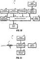
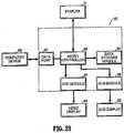
- the feedback controller 603is configured to store the data transmitted thereto by the instrument 10 as well as process and analyze the data.
- the feedback controller 603is also connected to other devices, such as a video display 604, a video processor 605 and a computing device 606 (e.g., a personal computer, a PDA, a smartphone, a storage device, etc.).
- the video processor 605is used for processing output data generated by the feedback controller 603 for output on the video display 604.
- the computing device 606is used for additional processing of the feedback data.
- the results of the sensor feedback analysis performed by the microcontroller 600may be stored internally for later retrieval by the computing device 606.
- the microcontroller 600is connected to the drive motor 200 and is configured and arranged to monitor the battery impedance, voltage, temperature and/or current draw and to control the operation of the instrument 10.
- the load or loads on battery 400, transmission, drive motor 200 and drive components of the instrument 10are determined to control a motor speed if the load or loads indicate a damaging limitation is reached or approached. For example, the energy remaining in battery 400, the number of firings remaining, whether battery 400 must be replaced or charged, and/or approaching the potential loading limits of the instrument 10 may be determined.
- the microcontroller 600may also be connected to one or more of the sensors of the instrument 10 discussed above.
- Figs. 24-25illustrate another embodiment of the instrument 10'.
- the instrument 10'includes a power source 400' having a plurality of cells 401 arranged in a straight configuration.
- the power source 400'is inserted vertically into a vertical battery chamber 800 within the handle portion 112.
- the battery chamber 800includes a spring 802 within the top portion thereof to push downward the power source 400'.
- the spring 802may include contacts to electrically couple with the power source 400'.
- the power source 400'is held within the battery chamber 800 via a battery cap 804 which is configured to slide in a distal direction to lock in place.
- the cap 804 and the handle 112may include tongue and groove couplings to keep the cap 804 from sliding out.
- the power source 400'is biased against the cap 804 due to the downward force of the spring 802. As the cap 804 is slid in a proximal direction, the power source 400' is ejected from the battery chamber 800 by the spring 802.
- the outer edge of the wheel 810is disposed between the opposing edges of the optical reader 812 such that the light being transmitted between the edges 814 and 816 shine through the slits 811.
- the light beam between the edges 814 and 816is interrupted by the wheel 810 as the drive tube 210 is rotated.
- the optical reader 812measures the number of interruptions in the light beam and rate of occurrences thereof and transmits these measurements to the speed calculator 422 which then determines the speed of the drive rod 220 as discussed above.
- the retraction gear 824is coupled to a first spindle 828 which is disposed in a substantially perpendicular manner between the top and bottom portions 823 and 825 of the retraction chassis 822 and is rotatable around a longitudinal axis defined thereby.
- the first spindle 828further includes a first spur gear 830 attached thereto and to the retraction gear 824.
- the first spur gear 830interfaces with a second spur gear 832 disposed on a second spindle 834 which is also is disposed in a substantially perpendicular manner between the top and bottom portions 823 and 825 of the retraction chassis 822 and is rotatable around a longitudinal axis defined thereby.
- the first and second clutch portions 838 and 842include a plurality of interlocking teeth 844 having a flat interlocking surface 846 and a sloping slip surface 848.
- the second clutch portion 842is pushed downwards by a retraction lever 845 thereby interfacing the teeth 844.
- the slip surfaces 848allow for the interlocking surfaces 846 to come in contact with each other thereby allowing rotation of the second clutch portion 842 to rotate the first clutch portion 838 and all of the interfacing gears.
- the lever 845can be rotated for a predetermined amount until the handle 849 abuts the housing 110 as shown in Fig. 28 . Thereafter, the lever 845 is brought back to its first configuration by the return extension spring 862. This raises the camming portion 847 allowing the second clutch portion 842 to also move upward and disengage the first clutch portion 838. The needle clutch 855 releases the fitting 856 allowing the lever 845 to return to the first configuration without affecting the movement of the drive tube 210. Once the lever 845 is returned to the first configuration, the lever 845 may be retracted once again to continue to ratchet the driving rod 220.
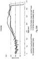
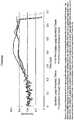
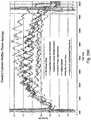
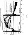
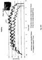
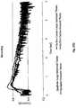
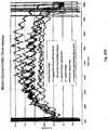
- the data storage module 502stores data from successful firing procedures (e.g., the waveform shown in Figs. 33A-33L , and Figs. 37A-37L ) which is used by the microcontroller 500 to determine whether each surgical fastener or row of fasteners are successfully deployed.
- the datamay be previously stored in the data storage module 502 by a manufacturer, uploaded by a user, or saved from a previous operation of the powered surgical instrument where all of the surgical fasteners were correctly deployed.
Landscapes
- Health & Medical Sciences (AREA)
- Life Sciences & Earth Sciences (AREA)
- Surgery (AREA)
- Heart & Thoracic Surgery (AREA)
- Engineering & Computer Science (AREA)
- Biomedical Technology (AREA)
- Nuclear Medicine, Radiotherapy & Molecular Imaging (AREA)
- Medical Informatics (AREA)
- Molecular Biology (AREA)
- Animal Behavior & Ethology (AREA)
- General Health & Medical Sciences (AREA)
- Public Health (AREA)
- Veterinary Medicine (AREA)
- Surgical Instruments (AREA)
Description
- The present disclosure relates to a surgical stapler for implanting mechanical surgical fasteners into the tissue of a patient, and, in particular, to a surgical stapler which is powered by a motor for firing surgical fasteners into tissue and a controller for determining one or more conditions related to the firing of the surgical fasteners and controlling the stapler in response to one or more sensed feedback signals.
- Current known devices can typically require 4.5kg to 27.2kg (10-60 pounds ) of manual hand force to clamp tissue and deploy and form surgical fasteners in tissue which, over repeated use, can cause a surgeon's hand to become fatigued. Gas powered pneumatic staplers which implant surgical fasteners into tissue are known in the art. Certain of these instruments utilize a pressurized gas supply which connects to a trigger mechanism. The trigger mechanism, when depressed, simply releases pressurized gas to implant a fastener into tissue.
- Motor-powered surgical staplers are also known in the art. These include powered surgical staplers having motors which activate staple firing mechanisms. In some instances, the stapler firing mechanism may improperly deploy surgical fasteners that may have negative effects on the patient. Thus, there is a need for new and improved powered surgical staplers that include various sensors. The sensors detect improperly deployed surgical fasteners and provide relevant feedback to a controller or user regarding the same. Document
EP2055243 discloses a powered surgical stapler according to the preamble ofclaim 1. - According to one aspect of the present disclosure, a powered surgical stapler is disclosed. The stapler includes a housing, an endoscopic portion extending distally from the housing and defining a first longitudinal axis, a drive motor disposed at least partially within a housing and a firing rod disposed in mechanical cooperation with the drive motor. The firing rod is translated longitudinally and is rotatable by the motor about the first longitudinal axis extending therethrough. The stapler also includes an end effector disposed adjacent a distal portion of the endoscopic portion. The end effector is in mechanical cooperation with the firing rod to fire a surgical fastener. The stapler further includes a current sensor configured to measure a current draw on the motor and a controller configured to determine whether the surgical fastener is successfully deployed based on the current draw on the motor.
- According to another aspect of the present disclosure, a method for detecting a successful deployment of a surgical fastener is provided. The method includes providing a powered surgical stapler. The stapler includes a housing, an endoscopic portion extending distally from the housing and defining a first longitudinal axis, a drive motor disposed at least partially within a housing and a firing rod disposed in mechanical cooperation with the drive motor. The firing rod is translated longitudinally and is rotatable by the motor about the first longitudinal axis extending therethrough. The stapler also includes an end effector disposed adjacent a distal portion of the endoscopic portion. The end effector is in mechanical cooperation with the firing rod to fire a surgical fastener. The stapler further includes a current sensor configured to measure a current draw on the motor and a controller configured to determine whether the surgical fastener is successfully deployed based on the current draw on the motor. The stapler fires the surgical fastener and detects the current draw on the motor. The detected current draw is compared to successful test firing data and the result of the comparison between the detected current draw and the successful test firing data is outputted.
- Various embodiments of the subject instrument are described herein with reference to the drawings wherein:
Fig. 1 is a perspective view of a powered surgical instrument according to an embodiment of the present disclosure;Fig. 2 is a partial enlarged perspective view of the powered surgical instrument according to the embodiment of the present disclosure ofFig. 1 ;Fig. 3 is a partial enlarged plan view of the powered surgical instrument according to the embodiment of the present disclosure ofFig. 1 ;Fig. 4 is a partial perspective sectional view of internal components of the powered surgical instrument ofFig. 1 in accordance with an embodiment of the present disclosure;Fig. 5 is a perspective view of an articulation mechanism with parts separated of the powered surgical instrument ofFig. 1 in accordance with an embodiment of the present disclosure;Fig. 6 is a partial cross-sectional view showing internal components of the powered surgical instrument according to the embodiment of the present disclosure ofFig. 1 disposed in a first position;Fig. 7 is a partial cross-sectional view showing internal components of the powered surgical instrument according to the embodiment of the present disclosure ofFig. 1 disposed in a second position;FIG. 8 is a perspective view of the mounting assembly and the proximal body portion of a loading unit with parts separated of the powered surgical instrument ofFig. 1 in accordance with an embodiment of the present disclosure;FIG. 9 is a side cross-sectional view of an end effector of the powered surgical instrument ofFig. 1 in accordance with an embodiment of the present disclosure;Fig. 10 is a partial enlarged side view showing internal components of the powered surgical instrument according to the embodiment of the present disclosure ofFig. 1 ;Fig. 11 is a perspective view of a unidirectional clutch plate of the powered surgical instrument ofFig. 1 in accordance with an embodiment of the present disclosure;Fig. 12 is a partial enlarged side view showing internal components of the powered surgical instrument according to the embodiment of the present disclosure ofFig. 1 ;Fig. 13 is a schematic diagram of a power source of the powered surgical instrument according to the embodiment of the present disclosure ofFig. 1 ;Fig. 14 is a flow chart diagram illustrating a method for authenticating the power source of the powered surgical instrument ofFig. 1 ;Figs. 15A-B are partial perspective rear views of a loading unit of the powered surgical instrument according to the embodiment of the present disclosure ofFig. 1 ;Fig. 16 is a flow chart diagram illustrating a method for authenticating the loading unit of the powered surgical instrument according to the embodiment of the present disclosure ofFig. 1 ;Fig. 17 is a perspective view of the loading unit of the powered surgical instrument according to the embodiment of the present disclosure ofFig. 1 ;Fig. 18 is a side cross-sectional view of the end effector of the powered surgical instrument ofFig. 1 in accordance with an embodiment of the present disclosure;Fig. 19 is a side cross-sectional view of the powered surgical instrument ofFig. 1 in accordance with an embodiment of the present disclosure;Fig. 20 is a schematic diagram of a control system of the powered surgical instrument according to the embodiment of the present disclosure ofFig. 1 ;Fig. 21 is a schematic diagram of a feedback control system according to the present disclosure;Figs. 22A-B are perspective front and rear views of a feedback controller of the feedback control system according to the embodiment of the present disclosure;Fig. 23 is a schematic diagram of the feedback controller according to the embodiment of the present disclosure;Fig. 24 is a partial sectional view of internal components of a powered surgical instrument in accordance with an embodiment of the present disclosure;Fig. 25 is a partial perspective sectional view of internal components of the powered surgical instrument in accordance with an embodiment of the present disclosure;Fig. 26 is a partial perspective view of a nose assembly of the powered surgical instrument in accordance with an embodiment of the present disclosure;Fig. 27 is a partial perspective view of a retraction lever of the powered surgical instrument in accordance with an embodiment of the present disclosure;Fig. 28 is a partial perspective view of the powered surgical instrument in accordance with an embodiment of the present disclosure;Fig. 29 is a perspective view of the powered surgical instrument in accordance with an embodiment of the present disclosure;Fig. 30 is a perspective view of a modular retraction assembly of the powered surgical instrument in accordance with an embodiment of the present disclosure;Fig. 31 is an enlarged partial sectional view of internal components of a powered surgical instrument in accordance with an embodiment of the present disclosure;Fig. 32 is an enlarged partial sectional view of internal components of a powered surgical instrument in accordance with an embodiment of the present disclosure;Figs. 33A - 33L are color charts depicting the current drawn by a motor versus time in a powered surgical instrument in accordance with embodiments of the present disclosure;Fig. 34 is a schematic diagram of a surgical fastener detection system in accordance with an embodiment of the present disclosure;Fig. 35 is a schematic of a current sensing circuit in accordance with an embodiment of the present invention;Fig. 36 is a flow chart diagram illustrating a method for detecting successful deployment of one or more surgical fasteners; andFigs. 31A-31L are gray-scale representations of the color charts provided inFigs. 33A-33L .- Embodiments of the presently disclosed powered surgical instrument are now described in detail with reference to the drawings, in which like reference numerals designate identical or corresponding elements in each of the several views. As used herein the term "distal" refers to that portion of the powered surgical instrument, or component thereof, farther from the user while the term "proximal" refers to that portion of the powered surgical instrument or component thereof, closer to the user.
- A powered surgical instrument, e.g., a surgical stapler, in accordance with the present disclosure is referred to in the figures as
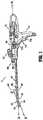
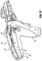
reference numeral 10. Referring initially toFig. 1 , poweredsurgical instrument 10 includes ahousing 110, anendoscopic portion 140 defining a first longitudinal axis A-A extending therethrough, and anend effector 160, defining a second longitudinal axis B-B extending therethrough.Endoscopic portion 140 extends distally fromhousing 110 and theend effector 160 is disposed adjacent a distal portion ofendoscopic portion 140. In an embodiment, the components of thehousing 110 are sealed against infiltration of particulate and/or fluid contamination and help prevent damage of the component by the sterilization process. - According to an embodiment of the present disclosure,
end effector 160 includes a first jaw member having one or more surgical fasteners (e.g., cartridge assembly 164) and a second opposing jaw member including an anvil portion for deploying and forming the surgical fasteners (e.g., an anvil assembly 162). In certain embodiments, the staples are housed incartridge assembly 164 to apply linear rows of staples to body tissue either in simultaneous or sequential manner. Either one or both of theanvil assembly 162 and thecartridge assembly 164 are movable in relation to one another between an open position in which theanvil assembly 162 is spaced fromcartridge assembly 164 and an approximated or clamped position in which theanvil assembly 162 is in juxtaposed alignment withcartridge assembly 164. - It is further envisioned that
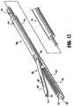
end effector 160 is attached to a mountingportion 166, which is pivotably attached to abody portion 168.Body portion 168 may be integral withendoscopic portion 140 of poweredsurgical instrument 10, or may be removably attached to theinstrument 10 to provide a replaceable, disposable loading unit (DLU) or single use loading unit (SULU) (e.g., loading unit 169). In certain embodiments, the reusable portion may be configured for sterilization and re-use in a subsequent surgical procedure. - The
loading unit 169 may be connectable toendoscopic portion 140 through a bayonet connection. It is envisioned that theloading unit 169 has an articulation link connected to mountingportion 166 of theloading unit 169 and the articulation link is connected to a linkage rod so that theend effector 160 is articulated as the linkage rod is translated in the distal-proximal direction along first longitudinal axis A-A. Other means of connectingend effector 160 toendoscopic portion 140 to allow articulation may be used, such as a flexible tube or a tube comprising a plurality of pivotable members. - The
loading unit 169 may incorporate or be configured to incorporate various end effectors, such as vessel sealing devices, linear stapling devices, circular stapling devices, cutters, etc. Such end effectors may be coupled toendoscopic portion 140 of poweredsurgical instrument 10. Theloading unit 169 may include a linear stapling end effector that does not articulate. An intermediate flexible shaft may be included betweenhandle portion 112 and loading unit. It is envisioned that the incorporation of a flexible shaft may facilitate access to and/or within certain areas of the body. - With reference to
Fig. 2 , an enlarged view of thehousing 110 is illustrated according to an embodiment of the present disclosure. In the illustrated embodiment,housing 110 includes ahandle portion 112 having amain drive switch 114 disposed thereon. Theswitch 114 may include first andsecond switches handle portion 112, which defines a handle axis H-H, is configured to be grasped by fingers of a user. Thehandle portion 112 has an ergonomic shape providing ample palm grip leverage which helps prevent thehandle portion 112 from being squeezed out of the user's hand during operation. Eachswitch handle portion 112 to facilitate its depression by a user's finger or fingers. - Additionally, and with reference to
Figs. 1 and2 ,switches Fig. 4 ). In one embodiment, theswitch 114a is configured to activate thedrive motor 200 in a first direction to advance firing rod 220 (Fig. 5 ) in a distal direction thereby clamping the anvil and thecartridge assemblies switch 114b may be configured to retract thefiring rod 220 to open the anvil andcartridge assemblies drive motor 200 in a reverse direction. The retraction mode initiates a mechanical lock out, preventing further progression of stapling and cutting by theloading unit 169. The toggle has a first position for activatingswitch 114a, a second position for activatingswitch 114b, and a neutral position between the first and second positions. The details of operation of the drive components of theinstrument 10 are discussed in more detail below. - The
housing 110, in particular thehandle portion 112, includes switch shields 117a and 117b. The switch shields 117a and 117b may have a rib-like shape surrounding the bottom portion of theswitch 114a and the top portion of theswitch 114b, respectively. Theswitch shield 117a and 117b prevent accidental activation of theswitch 114. Further, theswitches - In one embodiment, the
switches drive motor 200 and thefiring rod 220 in a non-linear manner. For example,switches 114a, b can be pressure-sensitive. This type of control interface allows for gradual increase in the rate of speed of the drive components from a slower and more precise mode to a faster operation. To prevent accidental activation of retraction, the switch 914b may be disconnected electronically until a fail safe switch is pressed. In addition athird switch 114c may also be used for this purpose. Additionally or alternatively, the fail safe can be overcome by pressing and holding theswitch 114b for a predetermined period of time from about 100 ms to about 2 seconds. The firingrod 220 then automatically retracts to its initial position unless theswitch 114b is activated (e.g., pressed and released) during the retraction mode to stop the retraction. Subsequent pressing of theswitch 114b after the release thereof resumes the retraction. Alternatively, the retraction of the firingrod 220 can continue to full retraction even if theswitch 114b is released, in other embodiments. - The
switches switches 114a and 144b may interface with the control circuit 115 by displacing or actuating variable control devices, such as rheostatic devices, multiple position switch circuit, linear and/or rotary variable displacement transducers, linear and/or rotary potentiometers, optical encoders, ferromagnetic sensors, and Hall Effect sensors. This allows theswitches drive motor 200 in multiple speed modes, such as gradually increasing the speed of thedrive motor 200 either incrementally or gradually depending on the type of the control circuit 115 being used, based on the depression of theswitches - In a particular embodiment, the
switch 114c may also be included (Figs. 1 ,2 and4 ), wherein depression thereof may mechanically and/or electrically change the mode of operation from clamping to firing. Theswitch 114c is recessed within the housing 11D and has high tactile feedback to prevent false actuations. Providing of a separate control switch to initialize the firing mode allows for the jaws of the end effector to be repeatedly opened and closed, so that theinstrument 10 is used as a grasper until theswitch 114c is pressed, thus activating the stapling and/or cutting. Theswitch 114 may include one or more microelectronic membrane switches, for example. Such a microelectronic membrane switch includes a relatively low actuation force, small package size, ergonomic size and shape, low profile, the ability to include molded letters on the switch, symbols, depictions and/or indications, and a low material cost. Additionally, switches 114 (such as microelectronic membrane switches) may be sealed to help facilitate sterilization of theinstrument 10, as well as helping to prevent particle and/or fluid contamination. - As an alternative to, or in addition to
switches 114, other input devices may include voice input technology, which may include hardware and/or software incorporated in a control system 501 (Fig. 20 ), or a separate digital module connected thereto. The voice input technology may include voice recognition, voice activation, voice rectification and/or embedded speech. The user may be able to control the operation of the instrument in whole or in part through voice commands, thus freeing one or both of the user's hands for operating other instruments. Voice or other audible output may also be used to provide the user with feedback. - Referring to
Fig. 3 , a proximal area 118 ofhousing 110 having auser interface 120 is shown. Theuser interface 120 includes a screen 122 and a plurality ofswitches 124. Theuser interface 120 may display various types of operational parameters of theinstrument 10 such as "mode" (e.g., rotation, articulation or actuation), which may be communicated to user interface via a sensor, "status" (e.g., angle of articulation, speed of rotation, or type of actuation) and "feedback," such as whether staples have been fired based on the information reported by the sensors disposed in theinstrument 10. - The screen 122 may be an LCD screen, a plasma screen, electroluminescent screen and the like. In one embodiment the screen 122 may be a touch screen, obviating the need for the
switches 124. The touch screen may incorporate resistive, surface wave, capacitive, infrared, strain gauge, optical, dispersive signal or acoustic pulse recognition touch screen technologies. The touch screen may be used to allow the user to provide input while viewing operational feedback. This approach may enable facilitation of sealing screen components to help sterilize theinstrument 10, as well as preventing particle and/or fluid contamination. In certain embodiments, screen is pivotably or rotatably mounted to theinstrument 10 for flexibility in viewing screen during use or preparation (e.g., via a hinge or ball-and-socket mount). - The
switches 124 may be used for starting and/or stopping movement of theinstrument 10 as well as selecting the pivot direction, speed and/or torque. It is also envisioned that at least oneswitch 124 can be used for selecting an emergency mode that overrides various settings. Theswitches 124 may also be used for selecting various options on the screen 122, such as responding to prompts while navigating user interface menus and selecting various settings, allowing a user input different tissue types, and various sizes and lengths of staple cartridges. - The
switches 124 may be formed from a micro-electronic tactile or non-tactile membrane, a polyester membrane, elastomer, plastic or metal keys of various shapes and sizes. Additionally, switches may be positioned at different heights from one another and/or may include raised indicia or other textural features (e.g., concavity or convexity) to allow a user to depress an appropriate switch without the need to look atuser interface 120. - In addition to the screen 122, the
user interface 120 may include one or more visual outputs 123 which may include one or more colored visible lights or light emitting diodes ("LED") to relay feedback to the user. The visual outputs 123 may include corresponding indicators of various shapes, sizes and colors having numbers and/or text which identify the visual outputs 123. The visual outputs 123 are disposed on top of thehousing 110 such that the outputs 123 are raised and protrude in relation to thehousing 110 providing for better visibility thereof. - The multiple lights display in a certain combination to illustrate a specific operational mode to the user. In one embodiment, the visual outputs 123 include a first light (e.g., yellow) 123a, a second light (e.g., green) 123b and a third light (e.g., red) 123c. The lights are operated in a particular combination associated with a particular operational mode as listed in Table 1 below.
Table 1 Light Combination Operational Mode Light Status No loading unit 169 or staple cartridge is loaded.First Light Off Second Light Off Third Light Off Light Status The loading unit 169 and/or staple cartridge are loaded and power is activated, allowing theend effector 160 to clamp as a grasper and articulate.First Light On Second Light Off Third Light Off Light Status A used loading unit 169 or staple cartridge is loaded.First Light Flashing Second Light Off Third Light Off Light Status Instrument 10 is deactivated and prevented from firing staples or cutting. First Light N/A Second Light Off Third Light N/A Light Status A new loading unit 169 is loaded, theend effector 160 is fully clamped and theinstrument 10 is in firing staple and cutting modes.First Light On Second Light On Third Light Off Light Status Due to high stapling forces a pulse mode is in effect, providing for a time delay during which tissue is compressed. First Light On Second Light Flashing Third Light Off Light Status No system errors detected. First Light N/A Second Light N/A Third Light Off Light Status Tissue thickness and/or firing load is too high, this warning can be overridden. First Light On Second Light On Third Light On Light Status Functional system error is detected, instrument 10 should be replaced.First Light N/A Second Light N/A Third Light Flashing - In another embodiment, the visual output 123 may include a single multicolored LED which display a particular color associated with the operational modes as discussed above with respect to the first, second and third lights in Table 1.
- The
user interface 120 also includes audio outputs 125 (e.g., tones, bells, buzzers, integrated speaker, etc.) to communicate various status changes to the user such as lower battery, empty cartridge, etc. The audible feedback can be used in conjunction with or in lieu of the visual outputs 123. The audible feedback may be provided in the forms of clicks, snaps, beeps, rings and buzzers in single or multiple pulse sequences. In one embodiment, a simulated mechanical sound may be prerecorded which replicates the click and/or snap sounds generated by mechanical lockouts and mechanisms of conventional non-powered instruments. This eliminates the need to generate such mechanical sounds through the actual components of theinstrument 10 and also avoids the use of beeps and other electronic sounds which are usually associated with other operating room equipment, thereby preventing confusion from extraneous audible feedback. - The
instrument 10 may also provide for haptic or vibratory feedback through a haptic mechanism (not explicitly shown) within thehousing 110. The haptic feedback may be used in conjunction with the auditory and visual feedback or in lieu thereof to avoid confusion with the operating room equipment which relies on audio and visual feedback. The haptic mechanism may be an asynchronous motor that vibrates in a pulsating manner. In one embodiment, the vibrations are at a frequency of about 30 Hz or above providing a displacement having an amplitude of 1.5 mm or lower to limit the vibratory effects from reaching theloading unit 169. - It is also envisioned that
user interface 120 includes different colors and/or intensities of text on screen and/or on switches for further differentiation between the displayed items. The visual, auditory or haptic feedback can be increased or decreased in intensity. For example, the intensity of the feedback may be used to indicate that the forces on the instrument are becoming excessive. Figs. 2-4 illustrate anarticulation mechanism 170, including anarticulation housing 172, apowered articulation switch 174, an articulation motor 132 and amanual articulation knob 176. Translation of thepowered articulation switch 174 or pivoting of themanual articulation knob 176 activates the articulation motor 132 which then actuates anarticulation gear 233 of thearticulation mechanism 170 as shown in Fig. C. Actuation ofarticulation mechanism 170 causes theend effector 160 to move from its first position, where longitudinal axis B-B is substantially aligned with longitudinal axis A-A, towards a position in which longitudinal axis B-B is disposed at an angle to longitudinal axis A-A. Preferably, a plurality of articulated positions is achieved. Thepowered articulation switch 174 may also incorporate similar non-linear speed controls as the clamping mechanism as controlled by theswitches - Further, the
housing 110 includes switch shields 169 having a wing-like shape and extending from the top surface of thehousing 110 over theswitch 174. The switch shields 169 prevent accidental activation of theswitch 174 and require the user to reach below theshield 169 in order to activate thearticulation mechanism 170. - Additionally,
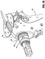
articulation housing 172 andpowered articulation switch 174 are mounted to arotating housing assembly 180. Rotation of arotation knob 182 about first longitudinal axis A-A causeshousing assembly 180 as well asarticulation housing 172 andpowered articulation switch 174 to rotate about first longitudinal axis A-A, and thus causes corresponding rotation ofdistal portion 224 of firingrod 220 andend effector 160 about first longitudinal axis A-A. Thearticulation mechanism 170 is electromechanically coupled to first and secondconductive rings housing nose assembly 155 as shown inFigs. 4 and26 . The conductive rings 157 and 159 may be soldered and/or crimped onto thenose assembly 155 and are in electrical contact with thepower source 400 thereby providing electrical power to thearticulation mechanism 170. Thenose assembly 155 may be modular and may be attached to thehousing 110 during assembly to allow for easier soldering and/or crimping of the rings. Thearticulation mechanism 170 includes one or more brush and/or spring loaded contacts in contact with theconductive rings housing assembly 180 is rotated along with thearticulation housing 172 thearticulation mechanism 170 is in continuous contact with theconductive rings power source 400. - Further details of
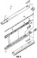
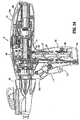
articulation housing 172,powered articulation switch 174,manual articulation knob 176 and providing articulation to endeffector 160 are described in detail in commonly-ownedU.S. Patent Application Serial No. 11/724,733 filed March 15, 2007 housing 110, may be utilized to control and/or record an articulation angle ofend effector 160 and/or position of the firingrod 220. Figs. 4-8 illustrate various internal components of theinstrument 10, including adrive motor 200, adrive tube 210 and afiring rod 220 having aproximal portion 222 and adistal portion 224. Thedrive tube 210 is rotatable about drive tube axis C-C extending therethrough.Drive motor 200 is disposed in mechanical cooperation withdrive tube 210 and is configured to rotate thedrive tube 210 about drive gear axis C-C. In one embodiment, thedrive motor 200 may be an electrical motor or a gear motor, which may include gearing incorporated within its housing.- The
housing 110 may be formed from twohalves 110a and 110b as illustrated inFig. 3 . The twohousing portion halves 110a and 110b may be attached to each other using screws atboss locators 111 which align thehousing portions 110a and 110b. In addition, thehousing 110 may be formed from plastic and may include rubber support members applied to the internal surface of thehousing 110 via a two-shot molding process. The rubber support members may isolate the vibration of the drive components (e.g., drive motor 200) form the rest of theinstrument 10. - The
housing halves 110a and 110b may be attached to each via a thin section of plastic (e.g., a living hinge) that interconnects thehalves 110a and 110b allowing thehousing 110 to be opened by breaking away thehalves 110a and 110b. - In one embodiment, the drive components (e.g., including a
drive motor 200, adrive tube 210 and afiring rod 220, etc.) may be mounted on a support plate allowing the drive components to be removed from thehousing 110 after theinstrument 10 has been used. The support plate mounting in conjunction with the hingedhousing halves 110a and 110b provide for reusability and recyclability of specific internal components while limiting contamination thereof. - With reference to
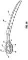
Figs. 4-6 , a firingrod coupling 190 is illustrated. Firingrod coupling 190 provides a link between theproximal portion 222 and thedistal portion 224 of the firingrod 220. Specifically, the firingrod coupling 190 enables rotation of thedistal portion 224 of the firingrod 220 with respect toproximal portion 222 of firingrod 220. Thus, firingrod coupling 190 enablesproximal portion 222 of firingrod 220 to remain non-rotatable, as discussed below with reference to analignment plate 350, while allowing rotation ofdistal portion 224 of firing rod 220 (e.g., upon rotation of rotation knob 182). - With reference to
Figs. 5 and6 , theproximal portion 222 of firingrod 220 includes a threadedportion 226, which extends through an internally-threadedportion 212 ofdrive tube 210. This relationship between firingrod 220 and drivetube 210causes firing rod 220 to move distally and/or proximally, in the directions of arrows D and E, along threadedportion 212 ofdrive tube 210 upon rotation ofdrive tube 210 in response to the rotation of thedrive motor 200. As thedrive tube 210 rotates in a first direction (e.g., clockwise), firingrod 220 moves proximally as illustrated inFig. 5 , the firingrod 220 is disposed at its proximal-most position. As thedrive tube 210 rotates in a second direction (e.g., counter-clockwise), firingrod 220 moves distally as illustrated inFig. 6 , the firingrod 220 is disposed at its distal-most position. - The firing
rod 220 is distally and proximally translatable within particular limits. Specifically, afirst end 222a ofproximal portion 222 of firingrod 220 acts as a mechanical stop in combination with analignment plate 350. That is, upon retraction when firingrod 220 is translated proximally,first end 222a contacts adistal surface 351 ofalignment plate 350, thus preventing continued proximal translation of firingrod 220 as shown inFig. 5 . Additionally, threadedportion 226 of theproximal portion 222 acts as a mechanical stop in combination withalignment plate 350. That is, when firingrod 220 is translated distally, the threadedportion 226 contacts aproximal surface 353 of thealignment plate 350, thus preventing further distal translation of firingrod 220 as shownFig. 6 . Thealignment plate 350 includes an aperture therethrough, which has a non-round cross-section. The non-round cross-section of the aperture prevents rotation ofproximal portion 222 of firingrod 220, thus limitingproximal portion 222 of firingrod 220 to axial translation therethrough. Further, aproximal bearing 354 and adistal bearing 356 are disposed at least partially arounddrive tube 210 for facilitation of rotation ofdrive tube 210, while helping aligndrive tube 210 withinhousing 110. - Rotation of
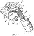
drive tube 210 in a first direction (e.g., counter-clockwise) corresponds with distal translation of the firingrod 220 which actuatesjaw members end effector 160 to grasp or clamp tissue held therebetween. Additional distal translation of firingrod 220 ejects surgical fasteners from theend effector 160 to fasten tissue by actuating cam bars and/or an actuation sled 74 (Fig. 9 ). Further, the firingrod 220 may also be configured to actuate a knife (not explicitly shown) to sever tissue. Proximal translation of firingrod 220 corresponding with rotation of thedrive tube 210 in a second direction (e.g., clockwise) actuatesjaw members end effector 160 are described in detail in commonly-ownedU.S. Patent No. 6,953,139 to Milliman et al. (the '139 Milliman patent). Fig. 8 shows an exploded view of theloading unit 169. Theend effector 160 may be actuated by anaxial drive assembly 213 having a drive beam or drive member 266. The distal end of thedrive beam 213 may include a knife blade. In addition, thedrive beam 213 includes aretention flange 40 having a pair of cam members 40a which engage the anvil and thecartridge assembly drive beam 213 longitudinally. Thedrive beam 213 advances anactuation sled 74 longitudinally through thestaple cartridge 164. Thesled 74 has cam wedges for engaging pushers 68 disposed in slots of thecartridge assembly 164, as thesled 74 is advanced. Staples 66 disposed in the slots are driven through tissue and against theanvil assembly 162 by the pushers 66.- With reference to
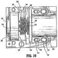
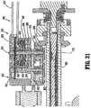
Fig. 8 , adrive motor shaft 202 is shown extending from aplanetary gear 204 that is attached to drivemotor 200. Drivemotor shaft 202 is in mechanical cooperation withclutch 300. Drivemotor shaft 202 is rotated by thedrive motor 200, thus resulting in rotation ofclutch 300.Clutch 300 includes aclutch plate 302 and aspring 304 and is shown having wedgedportions 306 disposed onclutch plate 302, which are configured to mate with an interface (e.g., wedges 214) disposed on aproximal face 216 ofdrive tube 210. Spring 304 is illustrated betweenplanetary gear 204 and drivetube 210. Specifically, and in accordance with the embodiment illustrated inFig. 8 ,spring 304 is illustrated betweenclutch face 302 and aclutch washer 308. Additionally, drivemotor 200 andplanetary gear 204 are mounted on amotor mount 310. As illustrated inFig. 8 ,motor mount 310 is adjustable proximally and distally with respect tohousing 110 viaslots 312 disposed inmotor mount 310 andprotrusions 314 disposed onhousing 110.- In an embodiment of the disclosure, the clutch 300 is implemented as a slip unidirectional clutch to limit torque and high inertia loads on the drive components.
Wedged portions 306 ofclutch 300 are configured and arranged to slip with respect towedges 214 ofproximal face 216 ofdrive tube 210 unless a threshold force is applied toclutch plate 302 viaclutch spring 304. Further, whenspring 304 applies the threshold force needed for wedgedportions 306 andwedges 214 to engage without slipping,drive tube 210 will rotate upon rotation ofdrive motor 200. It is envisioned that wedgedportions 306 and/orwedges 214 are configured to slip in one and/or both directions (i.e., clockwise and/or counter-clockwise) with respect to one another until a threshold force is attained. - As illustrated in
Figs. 10 and11 , the clutch 300 is shown with a unidirectionalclutch plate 700. Theclutch plate 700 includes a plurality of wedgedportions 702 having aslip face 704 and agrip face 706. Theslip face 704 has a curved edge which engages thewedges 214 of thedrive tube 210 up to a predetermined load. Thegrip face 706 has a flat edge which fully engages thedrive tube 210 and prevents slippage. When theclutch plate 700 is rotated in a first direction (e.g., clockwise) thegrip face 706 of the wedgedportions 702 engage thewedges 214 without slipping, providing for full torque from thedrive motor 200. When theclutch plate 700 is rotated in a reverse direction (e.g., counterclockwise) theslip face 704 of the wedgedportions 702 engage thewedges 214 and limit the torque being transferred to thedrive tube 210. Thus, if the load being applied to theslip face 704 is over the limit, the clutch 300 slips and thedrive tube 210 is not rotated. This prevents high load damage to theend effector 160 or tissue which can occur due to the momentum and dynamic friction of the drive components. More specifically, the drive mechanism of theinstrument 10 can drive thedrive rod 220 in a forward direction with less torque than in reverse. Use of a unidirectional clutch eliminates this problem. In addition electronic clutch may also be used to increase the motor potential during retraction (e.g., driving thedrive rod 220 in reverse) as discussed in more detail below. - It is further envisioned that drive
motor shaft 202 includes a D-shapedcross-section 708, which includes a substantiallyflat portion 710 and arounded portion 712. Thus, whiledrive motor shaft 202 is translatable with respect toclutch plate 302, drivemotor shaft 202 will not "slip" with respect toclutch plate 302 upon rotation ofdrive motor shaft 202. That is, rotation ofdrive motor shaft 202 will result in a slip-less rotation ofclutch plate 302. - The loading unit, in certain embodiments according to the present disclosure, includes an axial drive assembly that cooperates with firing
rod 220 toapproximate anvil assembly 162 andcartridge assembly 164 ofend effector 160, and fire staples from the staple cartridge. The axial drive assembly may include a beam that travels distally through the staple cartridge and may be retracted after the staples have been fired, as discussed above and as disclosed in certain embodiments of the '139 Milliman patent. - With reference to
Fig. 4 , theinstrument 10 includes apower source 400 which may be a rechargeable battery (e.g., lead-based, nickel-based, lithium-ion based, etc.). It is also envisioned that thepower source 400 includes at least one disposable battery. The disposable battery may be between about 9 volts and about 30 volts. - The
power source 400 includes one ormore battery cells 401 depending on the current load needs of theinstrument 10. Further, thepower source 400 includes one ormore ultracapacitors 402 which act as supplemental power storage due to their much higher energy density than conventional capacitors. Ultracapacitors 402 can be used in conjunction with thecells 401 during high energy draw. Theultracapacitors 402 can be used for a burst of power when energy is desired/required more quickly than can be provided solely by the cells 401 (e.g., when clamping thick tissue, rapid firing, clamping, etc.), ascells 401 are typically slow-drain devices from which current cannot be quickly drawn. This configuration can reduce the current load on the cells thereby reducing the number ofcells 401. It is envisioned thatcells 401 can be connected to theultracapacitors 402 to charge the capacitors. - The
power source 400 may be removable along with thedrive motor 200 to provide for recycling of theses components and reuse of theinstrument 10. In another embodiment, thepower source 400 may be an external battery pack which is worn on a belt and/or harness by the user and wired to theinstrument 10 during use. - The
power source 400 is enclosed within an insulatingshield 404 which may be formed from an absorbent, flame resistant and retardant material. Theshield 404 prevents heat generated by thepower source 400 from heating other components of theinstrument 10. In addition, theshield 404 may also be configured to absorb any chemicals or fluids which may leak from thecells 402 during heavy use and/or damage. - The
power source 400 is coupled to a power adapter 406 which is configured to connect to an external power source (e.g., DC transformer). The external power source may be used to recharge thepower source 400 or provide for additional power requirements. The power adapter 406 may also be configured to interface with electrosurgical generators which can then supply power to theinstrument 10. In this configuration, theinstrument 10 also includes an AC-to-DC power source which converts RF energy from the electrosurgical generators and powers theinstrument 10. - In another embodiment the
power source 400 is recharged using an inductive charging interface. Thepower source 400 is coupled to an inductive coil (not explicitly shown) disposed within the proximal portion of thehousing 110. Upon being placed within an electromagnetic field, the inductive coil converts the energy into electrical current that is then used to charge thepower source 400. The electromagnetic field may be produced by a base station (not explicitly shown) which is configured to interface with the proximal portion of thehousing 110, such that the inductive coil is enveloped by the electromagnetic field. This configuration eliminates the need for external contacts and allows for the proximal portion of thehousing 110 to seal thepower source 400 and the inductive coil within a water-proof environment which prevents exposure to fluids and contamination. - With reference to
Fig. 5 , theinstrument 10 also includes one or more safety circuits such as a discharge circuit 410 and a motor andbattery operating module 412. For clarity, wires and other circuit elements interconnecting various electronic components of theinstrument 10 are not shown, but such electromechanical connections wires are contemplated by the present disclosure. Certain components of theinstrument 10 communicate wirelessly. - The discharge circuit 410 is coupled to a
switch 414 and aresistive load 417 which are in turn coupled to thepower source 400. Theswitch 414 may be a user activated or an automatic (e.g., timer, counter) switch which is activated when thepower source 400 needs to be fully discharged for a safe and low temperature disposal (e.g., at the end of surgical procedure). Once theswitch 414 is activated, theload 417 is electrically connected to thepower source 400 such that the potential of thepower source 400 is directed to theload 417. The automatic switch may be a timer or a counter which is automatically activated after a predetermined operational time period or number of uses to discharge thepower source 400. Theload 417 has a predetermined resistance sufficient to fully and safely discharge all of thecells 401. - The motor and
battery operating module 412 is coupled to one or morethermal sensors 413 which determine the temperature within thedrive motor 200 and thepower source 400 to ensure safe operation of theinstrument 10. The sensors may be an ammeter for determining the current draw within thepower source 400, a thermistor, a thermopile, a thermocouple, a thermal infrared sensor and the like. Monitoring temperature of these components allows for a determination of the load being placed thereon. The increase in the current flowing through these components causes an increase in temperature therein. The temperature and/or current draw data may then be used to control the power consumption in an efficient manner or assure safe levels of operation. - In order to ensure safe and reliable operation of the
instrument 10, it is desirable to ensure that thepower source 400 is authentic and/or valid (e.g., conforms to strict quality and safety standards) and operating within a predetermined temperature range. Authentication that thepower source 400 is valid minimizes risk of injury to the patient and/or the user due to poor quality. - With reference to
Fig. 9 , thepower source 400 is shown having one ormore battery cells 401, a temperature sensor 403 and an embeddedmicrocontroller 405 coupled thereto. Themicrocontroller 405 is coupled through wired and/or wireless communication protocols to microcontroller 500 (Fig. 14 ) of theinstrument 10 to authenticate thepower source 400. In one embodiment, the temperature sensor 403 can be coupled directly to themicrocontroller 500 instead of being coupled to the embeddedmicrocontroller 405. The temperature sensor 403 may be a thermistor, a thermopile, a thermocouple, a thermal infrared sensor, a resistance temperature detector, linear active thermistor, temperature-responsive color changing strips, bimetallic contact switches, and the like. The temperature sensor 403 reports the measured temperature to themicrocontroller 405 and/ormicrocontroller 500. - The embedded
microcontroller 405 executes a so-called challenge-response authentication algorithm with themicrocontroller 500 which is illustrated inFig. 10 . Instep 630, thepower source 400 is connected to theinstrument 10 and theinstrument 10 is switched on. Themicrocontroller 500 sends a challenge request to the embeddedmicrocontroller 405. Instep 632, themicrocontroller 405 interprets the challenge request and generates a response as a reply to the request. The response may include an identifier, such as a unique serial number stored in a radio frequency identification tag or in memory of themicrocontroller 405, a unique electrical measurable value of the power source 400 (e.g., resistance, capacitance, inductance, etc.). In addition, the response includes the temperature measured by the temperature sensor 403. - In step 634, the
microcontroller 500 decodes the response to obtain the identifier and the measured temperature. In step 636, themicrocontroller 500 determines if thepower source 400 is authentic based on the identifier, by comparing the identifier against a pre-approved list of authentic identifiers. If the identifier is not valid, theinstrument 10 is not going to operate and displays a "failure to authenticate battery" message via theuser interface 120. If the identifier is valid, the process proceeds to step 640 where the measured temperature is analyzed to determine if the measurement is within a predetermined operating range. If the temperature is outside the limit, theinstrument 10 also displays the failure message. Thus, if the temperature is within the predetermined limit and the identifier is valid, instep 642, the instrument commences operation, which may include providing a "battery authenticated" message to the user. - Referring back to
Figs. 4 and5 a plurality of sensors for providing feedback information relating to the function of theinstrument 10 are illustrated. Any combination of sensors may be disposed within theinstrument 10 to determine its operating stage, such as, staple cartridge load detection as well as status thereof, articulation, clamping, rotation, stapling, cutting and retracting, and the like. The sensors can be actuated by proximity, displacement or contact of various internal components of the instrument 10 (e.g., firingrod 220, drivemotor 200, etc.). - In the illustrated embodiments, the sensors can be rheostats (e.g., variable resistance devices), current monitors, conductive sensors, capacitive sensors, inductive sensors, thermal-based sensors, limit actuated switches, multiple position switch circuits, pressure transducers, linear and/or rotary variable displacement transducers, linear and/or rotary potentiometers, optical encoders, ferromagnetic sensors, Hall Effect sensors, and proximity switches. The sensors measure rotation, velocity, acceleration, deceleration, linear and/or angular displacement, detection of mechanical limits (e.g., stops), etc. This is attained by implementing multiple indicators arranged in either linear or rotational arrays on the mechanical drive components of the
instrument 10. The sensors then transmit the measurements to themicrocontroller 500 which determines the operating status of theinstrument 10. In addition, themicrocontroller 500 also adjusts the motor speed or torque of theinstrument 10 based on the measured feedback. - In embodiments where the clutch 300 is implemented as a slip clutch as shown in
Figs. 10 and11 , linear displacement sensors (e.g., linear displacement sensor 237) are positioned distally of the clutch 300 to provide accurate measurements. In this configuration, slippage of the clutch 300 does not affect the position, velocity and acceleration measurements recorded by the sensors. - With reference to
Fig. 4 , aload switch 230 is disposed within thearticulation housing 172. Theswitch 230 is connected in series with theswitch 114, preventing activation of theinstrument 10 unless theloading unit 169 is properly loaded into theinstrument 10. If theloading unit 169 is not loaded into theinstrument 10, the main power switch (e.g., switch 114) is open, thereby preventing use of any electronic or electric components of theinstrument 10. This also prevents any possible current draw from thepower source 400 allowing thepower source 400 to maintain a maximum potential over its specified shelf life. - Thus, the
switch 230 acts as a so-called "lock-out" switch which prevents false activation of theinstrument 10 since the switch is inaccessible to external manipulation and can only be activated by the insertion of theloading unit 169. Theswitch 230 is activated by displacement of a plunger or sensor tube as theloading unit 169 is inserted into theendoscopic portion 140. Once theswitch 230 is activated, the power from thepower source 400 is supplied to the electronic components (e.g., sensors,microcontroller 500, etc.) of theinstrument 10 providing the user with access to theuser interface 120 and other inputs/outputs. This also activates the visual outputs 123 to light up according to the light combination indicative of a properly loadedloading unit 169 wherein all the lights are off as described in Table 1. - More specifically, as shown in
Figs. 18 and19 , theendoscopic portion 140 includes a sensor plate 360 therein which is in mechanical contact with a sensor tube also disposed within theendoscopic portion 140 and around thedistal portion 224 of firingrod 220. Thedistal portion 224 of the firingrod 220 passes through an opening 368 at a distal end of a sensor cap 364. The sensor cap 364 includes a spring and abuts theswitch 230. This allows the sensor cap 364 to be biased against the sensor tube 362 which rests on the distal end of the sensor cap 364 without passing through the opening 368. Biasing of the sensor tube 362 then pushes out the sensor plate 360 accordingly. - When the
loading unit 169 is loaded into theendoscopic portion 140, theproximal portion 171 abuts the sensor plate 360 and displaces the plate 360 in a proximal direction. The sensor plate 360 then pushes the sensor tube 362 in the proximal direction which then applies pressure on the sensor cap 364 thereby compressing the spring 366 and activating theswitch 230 denoting that theloading unit 169 has been properly inserted. - Once the
loading unit 169 is inserted into the endoscopic portion, theswitch 230 also determines whether theloading unit 169 is loaded correctly based on the position thereof. If theloading unit 169 is improperly loaded, theswitch 114 is not activated and an error code is relayed to the user via the user interface 120 (e.g., all the lights are off as described in Table 1). If theloading unit 169 has already been fired, any mechanical lockouts have been previously activated or the staple cartridge has been used, theinstrument 10 relays the error via theuser interface 120, e.g., the first light 123a is flashing. - In one embodiment, a second lock-out switch 259 (
Fig. 4 ) coupled to themain switch 114 may be implemented in theinstrument 10 as a bioimpedance, capacitance or pressure sensor disposed on the top surface of thehandle portion 112 configured to be activated when the user grasps theinstrument 10. Thus, unless theinstrument 10 is grasped properly, the operation of theswitch 114 is disabled. - With reference to
Fig. 5 , theinstrument 10 includes aposition calculator 416 for determining and outputting current linear position of the firingrod 220. Theposition calculator 416 is electrically connected to alinear displacement sensor 237 and a rotationspeed detecting apparatus 418 is coupled to thedrive motor 200. Theapparatus 418 includes anencoder 420 coupled to the motor for producing two or more encoder pulse signals in response to the rotation of thedrive motor 200. Theencoder 420 transmits the pulse signals to theapparatus 418 which then determines the rotational speed of thedrive motor 200. Theposition calculator 416 thereafter determines the linear speed and position of the firing rod based on the rotational speed of thedrive motor 200 since the rotation speed is directly proportional to the linear speed of the firingrod 220. Theposition calculator 416 and thespeed calculator 422 are coupled to themicrocontroller 500 which controls thedrive motor 200 in response to the sensed feedback from thecalculators Fig. 20 . - The
instrument 10 includes first andsecond indicators firing rod 220, which determine the speed of firingrod 220 and the location of firingrod 220 with respect to drivetube 210 and/orhousing 110. For instance, a limit switch may be activated (e.g., shaftstart position sensor 231 and clamp position sensor 232) by sensing first andsecond indicators 320a and/or 320b (e.g., bumps, grooves, indentations, etc.) passing thereby to determine position of firingrod 220, speed of firingrod 220 and mode of the instrument 10 (e.g., clamping, grasping, firing, sealing, cutting, retracting). Further, the feedback received from first andsecond indicators rod 220 should stop its axial movement (e.g., whendrive motor 200 should cease) depending on the size of the particular loading unit attached thereto. - More specifically, as the firing
rod 220 is moved in the distal direction from its resting (e.g., initial) position, the first actuation of theposition sensor 231 is activated by thefirst indicator 320a which denotes that operation of theinstrument 10 has commenced. As the operation continues, the firingrod 220 is moved further distally to initiate clamping, which movesfirst indicator 320a to interface withclamp position sensor 232. Further advancement of the firingrod 220 moves thesecond indicator 320b to interface with theposition sensor 232 which indicates that theinstrument 10 has been fired. - As discussed above, the
position calculator 416 is coupled to alinear displacement sensor 237 disposed adjacent to thefiring rod 220. In one embodiment, thelinear displacement sensor 237 may be a magnetic sensor. The firingrod 220 may be magnetized or may include magnetic material therein. The magnetic sensor may be a ferromagnetic sensor or a Hall Effect sensor which is configured to detect changes in a magnetic field. As thefiring rod 220 is translated linearly due to the rotation of thedrive motor 200, the change in the magnetic field in response to the translation motion is registered by the magnetic sensor. The magnetic sensor transmits data relating to the changes in the magnetic field to theposition calculator 416 which then determines the position of the firingrod 220 as a function of the magnetic field data. - In one embodiment, a select portion of the firing
rod 220 may be magnetized, such as the threads of the internally-threadedportion 212 or other notches (e.g.,indicators 320a and/or 320b) disposed on thefiring rod 220 may include or be made from a magnetic material. This allows for correlation of the cyclical variations in the magnetic field with each discrete translation of the threads as the magnetized portions of the firingrod 220 are linearly translated. Theposition calculator 416 thereafter determines the distance and the position of the firingrod 220 by summing the number of cyclical changes in the magnetic field and multiplies the sum by a predetermined distance between the threads and/or notches. - In one embodiment, the
linear displacement sensor 237 may be a potentiometer or a rheostat. The firingrod 220 includes a contact (e.g., wiper terminal) disposed in electromechanical contact with thelinear displacement sensor 237. The contact slides along the surface of thelinear displacement sensor 237 as the firingrod 220 is moved in the distal direction by thedrive motor 200. As the contact slides across the potentiometer and/or the rheostat, the voltage of the potentiometer and the resistance of the rheostat vary accordingly. Thus, the variation in voltage and resistance is transmitted to theposition calculator 416 which then extrapolates the distance traveled by the firingrod 220 and/or thefiring rod coupling 190 and the position thereof. - In one embodiment, the
position calculator 416 is coupled to one ormore switches 421 which are actuated by the threads of the internally-threadedportion 212 or theindicators 320a and/or 320b as the firingrod 220 and thefiring rod coupling 190 are moved in the distal direction. Theposition calculator 416 counts the number of threads which activated theswitch 421 and then multiplies the number by a predetermined distance between the threads or theindicators 320a and/or 320b. - The
instrument 10 also includes aspeed calculator 422 which determines the current speed of a linearly movingfiring rod 220 and/or the torque being provided by thedrive motor 200. Thespeed calculator 422 is connected to thelinear displacement sensor 237 which allows thespeed calculator 422 to determine the speed of the firingrod 220 based on the rate of change of the displacement thereof. - The
speed calculator 422 is coupled to the rotationspeed detecting apparatus 424 which includes theencoder 426. Theencoder 426 transmits the pulses correlating to the rotation of thedrive motor 200 which thespeed calculator 422 then uses to calculate the linear speed of the firingrod 220. In another embodiment, thespeed calculator 422 is coupled to arotational sensor 239 which detects the rotation of thedrive tube 210, thus, measuring the rate of rotation of thedrive tube 210 which allows for determination of the linear velocity of the firingrod 220. - The
speed calculator 422 is also coupled to avoltage sensor 428 which measures the back electromotive force ("EMF") induced in thedrive motor 200. The back EMF voltage of thedrive motor 200 is directly proportional to the rotational speed of thedrive motor 200 which, as discussed above, is used to determine the linear speed of the firingrod 220. - Monitoring of the speed of the
drive motor 200 can also be accomplished by measuring the voltage across the terminals thereof under constant current conditions. An increase in a load of thedrive motor 200 yields a decrease in the voltage applied at the motor terminals, which is directly related to the decrease in the speed of the motor. Thus, measuring the voltage across thedrive motor 200 provides for determining the load being placed thereon. In addition, by monitoring the change of the voltage over time (dV/dt), themicroprocessor 500 can detect a quick drop in voltage which correlates to a large change in the load or an increase in temperature of thedrive motor 200 and/or thepower source 400. - In a further embodiment, the
speed calculator 422 is coupled to a current sensor 430 (e.g., an ammeter). Thecurrent sensor 430 is in electrical communication with ashunt resistor 432 which is coupled to thedrive motor 200. Thecurrent sensor 430 measures the current being drawn by thedrive motor 200 by measuring the voltage drop across theresistor 432. Since the current used to power thedrive motor 200 is proportional to the rotational speed of thedrive motor 200 and, hence, the linear speed of the firingrod 220, thespeed calculator 422 determines the speed of the firingrod 220 based on the current draw of thedrive motor 200. - The
speed calculator 422 may also be coupled to a second voltage sensor (not explicitly shown) for determining the voltage within thepower source 400 thereby calculating the power draw directly from the source. In addition, the change in current over time (dl/dt) can be monitored to detect quick spikes in the measurements which correspond to a large increase in applied torque by thedrive motor 200. Thus, thecurrent sensor 430 is used to determine the speed and the load of thedrive motor 200. - In addition, the velocity of the firing
rod 220 as measured by thespeed calculator 422 may be then compared to the current draw of thedrive motor 200 to determine whether thedrive motor 200 is operating properly. Namely, if the current draw is not commensurate (e.g., large) with the velocity (e.g., low) of the firingrod 220 then themotor 200 is malfunctioning (e.g., locked, stalled, etc.). If a stall situation is detected, or the current draw exceeds predetermined limits, theposition calculator 416 then determines whether the firingrod 220 is at a mechanical stop. If this is the case, then themicrocontroller 500 can shut down thedrive motor 200 or enters a pulse and/or pause mode (e.g., discontinuous supply of power to the drive motor 200) to unlock theinstrument 10 and retract thefiring rod 220. - In one embodiment, the
speed calculator 422 compares the rotation speed of thedrive tube 210 as detected by therotation sensor 239 and that of thedrive motor 200 based on the measurements from and the rotationspeed detecting apparatus 424. This comparison allows thespeed calculator 422 to determine whether there is clutch activation problem (e.g., slippage) if there is a discrepancy between the rotation of the clutch 300 and that of thedrive tube 210. If slippage is detected, theposition calculator 416 then determines whether the firingrod 220 is at a mechanical stop. If this is the case, then themicrocontroller 500 can shut down theinstrument 10 or enter a pulse and/or pause mode (e.g., discontinuous supply of power to the drive motor 200), or retract thefiring rod 220. - In addition to linear and/or rotational displacement of the firing
rod 220 and other drive components, theinstrument 10 also includes sensors adapted to detect articulation of theend effector 160. With reference toFig. 4 , theinstrument 10 includes arotation sensor 241 adapted to indicate the start position, the rotational direction and the angular displacement of therotating housing assembly 180 at the start of the procedure as detected by the shaftstart position sensor 231. Therotation sensor 241 operates by counting the number of indicators disposed on the inner surface of therotation knob 182 by which therotation knob 182 has been rotated. The count is then transmitted to themicrocontroller 500 which then determines the rotational position of the endoscopic portion 142. This can be communicated wirelessly or through an electrical connection on the endoscopic portion and wires to themicrocontroller 500. - The
instrument 10 also includes anarticulation sensor 235 which determines articulation of theend effector 160. Thearticulation sensor 235 counts the number of 263 disposed on thearticulation gear 233 by which thearticulation knob 176 has been rotated from its 0° position, namely the center position of thearticulation knob 176 and, hence, of theend effector 160 as shown inFig. 5 . The 0° position and can be designated by a central unique indicator 265 also disposed on thearticulation gear 233 which corresponds with the first position of theend effector 160, where longitudinal axis B-B is substantially aligned with longitudinal axis A-A. The count is then transmitted to themicrocontroller 500 which then determines the articulation position of theend effector 160 and reports the articulation angle via theinterface 120. - In addition, the articulation angle can be used for the so-called "auto stop" mode. During this operational mode, the
instrument 10 automatically stops the articulation of theend effector 160 when theend effector 160 is at its central first position. Namely, as theend effector 160 is articulated from a position in which longitudinal axis B-B is disposed at an angle to longitudinal axis A-A towards the first position, the articulation is stopped when the longitudinal axis B-B is substantially aligned with longitudinal axis A-A. This position is detected by thearticulation sensor 235 based on the central indicator. This mode allows theendoscopic portion 140 to be extracted without the user having to manually align theend effector 160. - With reference to
Fig. 1 , the present disclosure provides a loadingunit identification system 440 which allows theinstrument 10 to identify theloading unit 169 and to determine operational status thereof. Theidentification system 440 provides information to theinstrument 10 on staple size, cartridge length, type of theloading unit 169, status of cartridge, proper engagement, and the like. This information allows the instrument to adjust clamping forces, speed of clamping and firing and end of stroke for various length staple cartridges. - The loading
unit identification system 440 may also be adapted to determine and communicate to the instrument 10 (e.g., acontrol system 501 shown inFig. 20 ) various information, including the speed, power, torque, clamping, travel length and strength limitations for operating theparticular end effector 160. Thecontrol system 501 may also determine the operational mode and adjust the voltage, clutch spring loading and stop points for travel of the components. More specifically, the identification system may include a component (e.g., a microchip, emitter or transmitter) disposed in theend effector 160 that communicates (e.g., wirelessly, via infrared signals, etc.) with thecontrol system 501, or a receiver therein. It is also envisioned that a signal may be sent via firingrod 220, such that firingrod 220 functions as a conduit for communications between thecontrol system 501 andend effector 160. In another embodiment, the signals can be sent through an intermediate interface, such as a feedback controlled 603 (Figs. 15-17 ). - By way of example, the sensors discussed above may be used to determine if the staples have been fired from the staple cartridge, whether they have been fully fired, whether and the extent to which the beam has been retracted proximally through the staple cartridge and other information regarding the operation of the loading unit. In certain embodiments of the present disclosure, the loading unit incorporates components for identifying the type of loading unit, and/or staple cartridge loaded on the
instrument 10, including infra red, cellular, or radio frequency identification chips. The type of loading unit and/or staple cartridge may be received by an associated receiver within thecontrol system 501, or an external device in the operating room for providing feedback, control and/or inventory analysis. - Information can be transmitted to the
instrument 10 via a variety of communication protocols (e.g., wired or wireless) between theloading unit 169 and theinstrument 10. The information can be stored within theloading unit 169 in a microcontroller, microprocessor, non-volatile memory, radio frequency identification tags, and identifiers of various types such as optical, color, displacement, magnetic, electrical, binary and gray coding (e.g., conductance, resistance, capacitance, impedance). - In one embodiment, the
loading unit 169 and theinstrument 10 include corresponding wireless transceivers, anidentifier 442 and aninterrogator 444 respectively. Theidentifier 442 includes memory or may be coupled to a microcontroller for storing various identification and status information regarding theloading unit 169. Once theloading unit 169 is coupled to theinstrument 10, theinstrument 10 interrogates theidentifier 442 via theinterrogator 444 for an identifying code. In response to the interrogatory, theidentifier 442 replies with the identifying code corresponding to theloading unit 169. During operation, once identification has occurred, theidentifier 442 is configured to provide theinstrument 10 with updates as to the status of the loading unit 169 (e.g., mechanical and/or electrical malfunction, position, articulation, etc.). - The
identifier 442 and theinterrogator 444 are configured to communicate with each other using one or more of the following communication protocols such as Bfuetooth®, ANT3®, KNX®, ZWave®, X10® Wireless USB®, IrDA®, Nanonet®, Tiny OS®, ZigBee®, 802.11 IEEE, and other radio, infrared, UHF, VHF communications and the like. In one embodiment, thetransceiver 400 may be a radio frequency identification (RFID) tag either active or passive, depending on the interrogator capabilities of thetransceiver 402. Figs. 11A and B illustrate additional embodiments of theloading unit 169 having various types of identification devices. With reference toFig. 11A , aproximal end 171 of theloading unit 169 having an electrical identifier 173 is shown. The identifier 173 may include one or more resistors, capacitors, inductors and is coupled with a correspondingelectrical contact 181 disposed on the distal end of theendoscopic portion 140. The contact may include slip rings, brushes and/or fixed contacts disposed in the endoscopic portion. The identifier 173 may be disposed on any location of theloading unit 168 and may be formed on a flexible or fixed circuit or may be traced directly on the surface of theloading unit 169.- When the
loading unit 169 is coupled with theendoscopic portion 140, the contact applies a small current through the electrical identifier 173. The interrogator contact also includes a corresponding electrical sensor which measures the resistance, impedance, capacitance, and/or impedance of the identifier 173. The identifier 173 has a unique electrical property (e.g., resistance, capacitance, inductance, etc.) which corresponds to the identifying code of theloading unit 169, thus, when the electrical property thereof is determined, theinstrument 10 determines the identity of theloading unit 169 based on the measured property. - In one embodiment, the identifier 173 may be a magnetic identifier such as gray coded magnets and/or ferrous nodes incorporating predetermined unique magnetic patterns identifying the
loading unit 169 by the identifying code. The magnetic identifier is read via a magnetic sensor (e.g., ferromagnetic sensor, Hall Effect sensor, etc.) disposed at the distal end of theendoscopic portion 140. The magnetic sensor transmits the magnetic data to theinstrument 10 which then determines the identity of theloading unit 169. Fig. 11B illustrates theproximal end 171 of theloading unit 169 having one or more protrusions 175. The protrusions 175 can be of any shape, such as divots, bumps, strips, etc., of various dimensions. The protrusions 175 interface withcorresponding displacement sensors 183 disposed within the proximal segment of theendoscopic portion 140. The sensors are displaced when the protrusions 175 are inserted into the endoscopic portion. The amount of the displacement is analyzed by the sensors and converted into identification data, allowing theinstrument 10 to determine staple size, cartridge length, type of theloading unit 169, proper engagement, and the like. The displacement sensors can be switches, contacts, magnetic sensors, optical sensors, variable resistors, linear and rotary variable displacement transducers which can be spring loaded. The switches are configured to transmit binary code to theinstrument 10 based on their activation status. More specifically, some protrusions 175 extend a distance sufficient to selectively activate some of the switches, thereby generating a unique code based on the combination of the protrusions 175.- In another embodiment, the protrusion 175 can be color coded. The
displacement sensors 183 include a color sensor configured to determine the color of the protrusion 175 to measure one or more properties of theloading unit 169 based on the color and transmits the information to theinstrument 10. Fig. 12 shows a method for identifying theloading unit 169 and providing status information concerning theloading unit 169 to theinstrument 10. In step 650 it is determined whether theloading unit 169 is properly loaded into theinstrument 10. This may be determined by detecting whether contact has been made with the identifier 173 and/or protrusions 175. If theloading unit 169 is properly loaded, in step 652, theloading unit 169 communicates to the instrument 10 a ready status (e.g., turning on the first light of the visual outputs 123).- In 654, the
instrument 10 verifies whether theloading unit 169 has been previously fired. Theidentifier 442 stores a value indicative of the previously fired status. If theloading unit 169 was fired, in step 656, theinstrument 10 provides an error response (e.g., flashing the first light of the visual outputs 123). If theloading unit 169 has not been fired, instep 658 theloading unit 169 provides identification and status information (e.g., first light is turned on) to theinstrument 10 via theidentification system 440. The determination whether theloading unit 169 has been fired is made based on the saved "previously fired" signal saved in the memory of theidentifier 442 as discussed in more detail below with respect to step 664. In step 660, theinstrument 10 adjusts its operating parameters in response to the information received from theloading unit 169. - The user performs a surgical procedure via the
instrument 10 in step 662. Once the procedure is complete and theloading unit 169 has been fired, theinstrument 10 transmits a "previously fired" signal to theloading unit 169. In step 664, theloading unit 169 saves the "previously fired" signal in the memory of theidentifier 442 for future interrogations by theinstrument 10 as discussed with respect to step 654. - With reference to
Fig. 13 , theloading unit 169 includes one or more tissue sensors disposed within theend effector 160 for detecting the type of object being grasped, such recognizing non-tissue objects and the tissue type of the object. The sensors are also configured to determine amount of blood flow being passed between the jaw members of theend effector 160. More specifically, afirst tissue sensor 177 is disposed at a distal portion of theanvil assembly 162 and a second tissue sensor 179 is disposed at a distal portion of thecartridge assembly 164. Thesensors 177 and 179 are coupled to theidentifier 442 allowing for transmission of sensor data to themicrocontroller 500 of theinstrument 10. - The
sensors 177 and 179 are adapted to generate a field and/or waves in one or more arrays or frequencies therebetween. Thesensors 177 and 179 may be acoustic, ultrasonic, ferromagnetic, Hall Effect sensors, laser, infrared, radio frequency, or piezoelectric devices. Thesensors 177 and 179 are calibrated for ignoring commonly occurring material, such as air, bodily fluids and various types of human tissue and for detecting certain types of foreign matter. The foreign matter may be bone, tendons, cartilage, nerves, major arteries and non-tissue matter, such as ceramic, metal, plastic, etc. - The
sensors 177 and 179 detect the foreign passing between the anvil andcartridge assemblies sensors 177 and 179 transmit the interference information to themicrocontroller 500 which then determines the type of the material being grasped by theend effector 160. The determination may be made by comparing the interference signals with a look up table listing various types of materials and their associated interference ranges. Themicrocontroller 500 then alerts the user of the foreign material being grasped as well as the identity thereof. This allows the user to prevent clamping, cutting or stapling through areas containing foreign matter. Fig. 20 illustrates acontrol system 501 including themicrocontroller 500 which is coupled to the position andspeed calculators unit identification system 440, theuser interface 120, thedrive motor 200, and adata storage module 502. In addition themicrocontroller 500 may be directly coupled to various sensors (e.g., first andsecond tissue sensors 177 and 179, theload switch 230, shaftstart position sensor 231, clampposition sensor 232,articulation sensor 235,linear displacement sensor 237,rotational sensor 239, firingrod rotation sensor 241, motor andbattery operating module 412, rotationspeed detecting apparatus 418, switches 421,voltage sensor 428,current sensor 430, theinterrogator 444, etc.).- The
microcontroller 500 includes internal memory which stores one or more software applications (e.g., firmware) for controlling the operation and functionality of theinstrument 10. Themicrocontroller 500 processes input data from theuser interface 120 and adjusts the operation of theinstrument 10 in response to the inputs. The adjustments to theinstrument 10 may including powering theinstrument 10 on or off, speed control by means of voltage regulation or voltage pulse width modulation, torque limitation by reducing duty cycle or pulsing the voltage on and off to limit average current delivery during a predetermined period of time. - The
microcontroller 500 is coupled to theuser interface 120 via auser feedback module 504 which is configured to inform the user of operational parameters of theinstrument 10. Theuser feedback module 504 instructs theuser interface 120 to output operational data on the screen 122. In particular, the outputs from the sensors are transmitted to themicrocontroller 500 which then sends feedback to the user instructing the user to select a specific mode, speed or function for theinstrument 10 in response thereto. - The loading
unit identification system 440 instructs themicrocontroller 500 which end effector is on the loading unit. In an embodiment, thecontrol system 501 is capable of storing information relating to the force applied to firingrod 220 and/orend effector 160, such that when theloading unit 169 is identified themicrocontroller 500 automatically selects the operating parameters for theinstrument 10. This allows for control of the force being applied to thefiring rod 220 so that firingrod 220 can drive theparticular end effector 160 that is on the loading unit in use at the time. - The
microcontroller 500 also analyzes the calculations from the position andspeed calculators rod 220 and operating status of components of theinstrument 10. The analysis may include interpretation of the sensed feedback signal from thecalculators rod 220 and other components of theinstrument 10 in response to the sensed signal. Themicrocontroller 500 is configured to limit the travel of the firingrod 220 once the firingrod 220 has moved beyond a predetermined point as reported by theposition calculator 416. Additional parameters which may be used by themicrocontroller 500 to control theinstrument 10 include motor and/or battery temperature, number of cycles remaining and used, remaining battery life, tissue thickness, current status of the end effector, transmission and reception, external device connection status, etc. - In one embodiment, the
instrument 10 includes various sensors configured to measure current (e.g., ammeter), voltage (e.g., voltmeter), proximity (e.g., optical sensors), temperature (e.g., thermocouples, thermistors, etc.), and force (e.g., strain gauges, load cells, etc.) to determine for loading conditions on theloading unit 169. During operation of theinstrument 10 it is desirable to know the forces being exerted by theinstrument 10 on the target tissue during the approximation process and during the firing process. Detection of abnormal loads (e.g., outside a predetermined load range) indicates a problem with theinstrument 10 and/or clamped tissue which is communicated to the user. - Monitoring of load conditions may be performed by one or more of the following methods: monitoring speed of the
drive motor 200, monitoring torque being applied by the motor, proximity ofjaw members instrument 10, measuring the load on thefiring rod 220 via a strain sensor 185 (Fig. 4 ) and/or other load bearing components of theinstrument 10. Speed and torque monitoring is discussed above with respect toFig. 5 and thespeed calculator 422. - Measuring the distance between the
jaw members end effector 160 and/or theinstrument 10. When large amounts of force are imparted on thejaw members jaw members jaw members strain gauges 187 and 189 as shown inFig. 13 to directly measure the load being exerted thereon. Alternatively, one or more proximity sensors 191 and 193 can be disposed at the distal tips of thejaw members microcontroller 500 which analyzes the angle and/or strain measurements and alerts the user of the stress on theend effector 160. - In another embodiment, the firing
rod 220 or other load-bearing components include one or more strain gauges and/or load sensors disposed thereon. Under high strain conditions, the pressure exerted on theinstrument 10 and/or theend effector 160 is translated to thefiring rod 220 causing the firingrod 220 to deflect, leading to increased strain thereon. The strain gauges then report the stress measurements to themicrocontroller 500. In another embodiment, a position, strain or force sensor may be disposed on theclutch plate 302. - During the approximation process, as the
end effector 160 is clamped about tissue, the sensors disposed in theinstrument 10 and/or theend effector 160 indicate to themicroprocessor 500 that theend effector 160 is deployed about abnormal tissue (e.g., low or high load conditions). Low load conditions are indicative of a small amount of tissue being grasped by theend effector 160 and high load conditions denote that too much tissue and/or a foreign object (e.g., tube, staple line, clips, etc.) is being grasped. Themicroprocessor 500 thereafter indicates to the user via theuser interface 120 that a moreappropriate loading unit 169 and/orinstrument 10 should be chosen. - During the firing process, the sensors can alert the user of a variety of errors. Sensors may communicate to the
microcontroller 500 that a staple cartridge or a portion of theinstrument 10 is faulty. In addition, the sensors can detect sudden spikes in the force exerted on the knife, which is indicative of encountering a foreign body. Monitoring of force spikes could also be used to detect the end of the firing stroke, such as when the firingrod 220 encounters the end of the stapling cartridge and runs into a hard stop. This hard stop creates a force spike which is relatively larger than those observed during normal operation of theinstrument 10 and could be used to indicate to the microcontroller that the firingrod 220 has reached the end ofloading unit 169. Measuring of the force spikes can be combined with positional feedback measurements (e.g., from an encoder, linear variable displacement transducer, linear potentiometer, etc.) as discussed with respect to position andspeed calculators instrument 10 without modifying theend effector 160. - When force spikes are encountered, the
instrument 10 notifies the user of the condition and takes preventative measures by entering a so-called "pulse" or an electronic clutching mode, which is discussed in more detail below. During this mode thedrive motor 200 is controlled to run only in short bursts to allow for the pressure between the grasped tissue and theend effector 160 to equalize. The electronic clutching limits the torque exerted by thedrive motor 200 and prevents situations where high amounts of current are drawn from thepower source 400. This, in turn, prevents damage to electronic and mechanical components due to overheating which accompanies overloading and high current draw situations. - The
microcontroller 500 controls thedrive motor 200 through a motor driver via a pulse width modulated control signal. The motor driver is configured to adjust the speed of thedrive motor 200 either in clockwise or counter-clockwise direction. The motor driver is also configured to switch between a plurality of operational modes which include an electronic motor braking mode, a constant speed mode, an electronic clutching mode, and a controlled current activation mode. In electronic braking mode, two terminal of thedrive motor 200 are shorted and the generated back EMF counteracts the rotation of thedrive motor 200 allowing for faster stopping and greater positional precision in adjusting the linear position of the firingrod 220. - In the constant speed mode, the
speed calculator 422 in conjunction with themicrocontroller 500 and/or the motor driver adjust the rotational speed of thedrive motor 200 to ensure constant linear speed of the firingrod 220. The electronic clutching mode involves repeat engagement and/or disengagement of the clutch 300 from thedrive motor 200 in response to sensed feedback signals from the position andspeed calculators - The
data storage module 502 records the data from the sensors coupled to themicrocontroller 500. In addition, thedata storage module 502 records the identifying code of theloading unit 169, the status of theend effector 100, number of stapling cycles during the procedure, etc. Thedata storage module 502 is also configured to connect to an external device such as a personal computer, a PDA, a smartphone, a storage device (e.g., Secure Digital® card, Compact Flash® card, MemoryStick®, etc. through a wireless or wireddata port 503. This allows thedata storage module 502 to transmit performance data to the external device for subsequent analysis and/or storage. Thedata port 503 also allows for so-called "in the field" upgrades of firmware of themicrocontroller 500. - A
feedback control system 601 is shown inFigs. 15-17 . The system includes afeedback controller 603 which is shown inFigs. 16A-B . Theinstrument 10 is connected to thefeedback controller 603 via thedata port 502 which may be either wired (e.g., Firewire®, USB®, Serial RS232®, Serial RS485®, USART®, Ethernet®, etc.) or wireless (e.g., Bluetooth®, ANT3®, KNX®, ZWave®, X10® Wireless USB®, IrDA®, Nanonet®, Tiny OS®, ZigBee®, 802.11 IEEE, and other radio, infrared, UHF, VHF communications and the like). - With reference to
Fig. 15 , thefeedback controller 603 is configured to store the data transmitted thereto by theinstrument 10 as well as process and analyze the data. Thefeedback controller 603 is also connected to other devices, such as avideo display 604, avideo processor 605 and a computing device 606 (e.g., a personal computer, a PDA, a smartphone, a storage device, etc.). Thevideo processor 605 is used for processing output data generated by thefeedback controller 603 for output on thevideo display 604. The computing device 606 is used for additional processing of the feedback data. In one embodiment, the results of the sensor feedback analysis performed by themicrocontroller 600 may be stored internally for later retrieval by the computing device 606. - The
feedback controller 603 includes a data port 607 (Fig. 16B ) coupled to themicrocontroller 600 which allows thefeedback controller 603 to be connected to the computing device 606. Thedata port 607 may provide for wired and/or wireless communication with the computing device 606 providing for an interface between the computing device 606 and thefeedback controller 603 for retrieval of stored feedback data, configuration of operating parameters of thefeedback controller 603 and upgrade of firmware and/or other software of thefeedback controller 603. - The
feedback controller 603 is further illustrated inFigs. 16A-B . Thefeedback controller 603 includes a housing 610 and a plurality of input and output ports, such as a video input 614, a video output 616, a heads-up ("HUD")display output 618. Thefeedback controller 603 also includes a screen 620 for displaying status information concerning thefeedback controller 603. - Components of the
feedback controller 603 are shown inFig. 17 . Thefeedback controller 603 includes amicrocontroller 600 and adata storage module 602. Themicrocontroller 600 and thedata storage module 602 provide a similar functionality as themicrocontroller 500 and thedata storage module 502 of theinstrument 10. Providing these components in a stand-alone module, in the form of thefeedback controller 603, alleviates the need to have these components within theinstrument 10. - The
data storage module 602 may include one or more internal and/or external storage devices, such as magnetic hard drives, flash memory (e.g., Secure Digital® card, Compact Flash® card, MemoryStick®, etc.) Thedata storage module 602 is used by thefeedback controller 603 to store feedback data from theinstrument 10 for later analysis of the data by the computing device 606. The feedback data includes information supplied by the sensors disposed within theinstrument 10 and the like. - The
microcontroller 600 is configured to supplant and/or supplement the control circuitry, if present, of theinstrument 10. Themicrocontroller 600 includes internal memory which stores one or more software application (e.g., firmware) for controlling the operation and functionality of theinstrument 10. Themicrocontroller 600 processes input data from theuser interface 120 and adjusts the operation of theinstrument 10 in response to the inputs. Themicrocontroller 600 is coupled to theuser interface 120 via auser feedback module 504 which is configured to inform the user of operational parameters of theinstrument 10. More specifically, theinstrument 10 is configured to connect to thefeedback controller 603 wirelessly or through a wired connection via a data port 407 (Fig. 5 ). - In a disclosed embodiment, the
microcontroller 600 is connected to thedrive motor 200 and is configured and arranged to monitor the battery impedance, voltage, temperature and/or current draw and to control the operation of theinstrument 10. The load or loads onbattery 400, transmission, drivemotor 200 and drive components of theinstrument 10 are determined to control a motor speed if the load or loads indicate a damaging limitation is reached or approached. For example, the energy remaining inbattery 400, the number of firings remaining, whetherbattery 400 must be replaced or charged, and/or approaching the potential loading limits of theinstrument 10 may be determined. Themicrocontroller 600 may also be connected to one or more of the sensors of theinstrument 10 discussed above. - The
microcontroller 600 is also configured to control the operation ofdrive motor 200 in response to the monitored information. Pulse modulation control schemes, which may include an electronic clutch, may be used in controlling theinstrument 10. For example, themicrocontroller 600 can regulate the voltage supply of thedrive motor 200 or supply a pulse modulated signal thereto to adjust the power and/or torque output to prevent system damage or optimize energy usage. - In one embodiment, an electric braking circuit may be used for controlling
drive motor 200, which uses the existing back electromotive force of rotatingdrive motor 200 to counteract and substantially reduce the momentum ofdrive tube 210. The electric braking circuit may improve the control ofdrive motor 200 and/or drivetube 210 for stopping accuracy and/or shift location of poweredsurgical instrument 10. Sensors for monitoring components of poweredsurgical instrument 10 and to help prevent overloading of poweredsurgical instrument 10 may include thermal-type sensors, such as thermal sensors, thermistors, thermopiles, thermo-couples and/or thermal infrared imaging and provide feedback to themicrocontroller 600. Themicrocontroller 600 may control the components of poweredsurgical instrument 10 in the event that limits are reached or approached and such control can include cutting off the power from thepower source 400, temporarily interrupting the power or going into a pause mode and/or pulse modulation to limit the energy used. Themicrocontroller 600 can also monitor the temperature of components to determine when operation can be resumed. The above uses of themicrocontroller 600 may be used independently of or factored with current, voltage, temperature and/or impedance measurements. - The result of the analysis and processing of the data by the
microcontroller 600 is output onvideo display 604 and/or theHUD display 622. Thevideo display 604 may be any type of display such as an LCD screen, a plasma screen, electroluminescent screen and the like. In one embodiment, thevideo display 604 may include a touch screen and may incorporate resistive, surface wave, capacitive, infrared, strain gauge, optical, dispersive signal or acoustic pulse recognition touch screen technologies. The touch screen may be used to allow the user to provide input while viewing operational feedback. TheHUD display 622 may be projected onto any surface visible to the user during surgical procedures, such as lenses of a pair of glasses and/or goggles, a face shield, and the like. This allows the user to visualize vital feedback information from thefeedback controller 603 without loosing focus on the procedure. - The
feedback controller 603 includes an on-screen display module 624 and a HUD module 626. The modules 626 process the output of themicrocontroller 600 for display on therespective displays OSD module 624 overlays text and/or graphical information from thefeedback controller 603 over other video images received from the surgical site via cameras disposed therein. The modified video signal having overlaid text is transmitted to thevideo display 604 allowing the user to visualize useful feedback information from theinstrument 10 and/orfeedback controller 603 while still observing the surgical site. Figs. 24-25 illustrate another embodiment of the instrument 10'. The instrument 10' includes a power source 400' having a plurality ofcells 401 arranged in a straight configuration. The power source 400' is inserted vertically into avertical battery chamber 800 within thehandle portion 112. Thebattery chamber 800 includes aspring 802 within the top portion thereof to push downward the power source 400'. In one embodiment, thespring 802 may include contacts to electrically couple with the power source 400'. The power source 400' is held within thebattery chamber 800 via abattery cap 804 which is configured to slide in a distal direction to lock in place. Thecap 804 and thehandle 112 may include tongue and groove couplings to keep thecap 804 from sliding out. The power source 400' is biased against thecap 804 due to the downward force of thespring 802. As thecap 804 is slid in a proximal direction, the power source 400' is ejected from thebattery chamber 800 by thespring 802.Fig. 25 shows another embodiment of therotational sensor 239 which detects the rotation of thedrive tube 210, thus, measuring the rate of rotation of thedrive tube 210 which allows for determination of the linear velocity of the firingrod 220. Therotational sensor 239 includes anencoder wheel 810 mounted to drivetube 210 and an optical reader 812 (e.g., photo interrupter). Theoptical reader 812 is configured to determine the number of interruptions in a light beam which is continuously provided between two opposingedges 814 and 816 thereof. Thewheel 810 rotates with thedrive tube 210 and includes a plurality ofslits 811 therethrough.- The outer edge of the
wheel 810 is disposed between the opposing edges of theoptical reader 812 such that the light being transmitted between theedges 814 and 816 shine through theslits 811. In other words, the light beam between theedges 814 and 816 is interrupted by thewheel 810 as thedrive tube 210 is rotated. Theoptical reader 812 measures the number of interruptions in the light beam and rate of occurrences thereof and transmits these measurements to thespeed calculator 422 which then determines the speed of thedrive rod 220 as discussed above. Fig. 27-32 show the instrument 10' having aretraction assembly 820 for retracting the firingrod 220 from its fired position. Theretraction assembly 820 provides for a manually driven mechanical interface with thedrive tube 210 allowing for manual retraction of the firingrod 210 via ratcheting action of theretraction assembly 820 in emergency situations (e.g., electrical malfunction,stuck end effector 160, etc.). Theretraction assembly 820 may be configured as a modular assembly which can be inserted into the instrument 10'.- With reference to
Fig. 30 , theretraction assembly 820 includes aretraction chassis 822 havingtop portion 823 and abottom portion 825. Theretraction assembly 820 interfaces mechanically with thedrive tube 210 via adrive gear 826 and aretraction gear 824. Thedrive gear 826 is attached to thedrive tube 210 and is translated in response to the rotation of thedrive tube 210. Conversely, rotation of thedrive gear 826 imparts rotation on thedrive tube 210. Thedrive gear 826 and theretraction gear 824 may be bevel gears allowing thegears - The
retraction gear 824 is coupled to afirst spindle 828 which is disposed in a substantially perpendicular manner between the top andbottom portions retraction chassis 822 and is rotatable around a longitudinal axis defined thereby. Thefirst spindle 828 further includes afirst spur gear 830 attached thereto and to theretraction gear 824. Thefirst spur gear 830 interfaces with asecond spur gear 832 disposed on asecond spindle 834 which is also is disposed in a substantially perpendicular manner between the top andbottom portions retraction chassis 822 and is rotatable around a longitudinal axis defined thereby. - The
second spur gear 832 interfaces mechanically with athird spur gear 836 which is disposed on thefirst spindle 828. Thethird spur gear 836 is attached to a firstclutch portion 838 of a unidirectionalclutch assembly 840. Theclutch assembly 840 further includes a secondclutch portion 840 rotatably disposed on thefirst spindle 828 above the firstclutch portion 838 with aspring 843 disposed between the first and secondclutch portions clutch portions Fig. 31 . - Rotation of the
drive tube 210 and/or thedrive gear 826 imparts rotation on theretraction gear 824 and the first, second and third spur gears 830, 832 and 836 along with thefirst portion 838 and therespective spindles clutch portion 842 can rotate about thespindle 828 and is separated from the firstclutch portion 838 by thespring 843, the rotation of thefirst portion 838 is not translated thereto. - The first and second
clutch portions teeth 844 having a flat interlocking surface 846 and a sloping slip surface 848. In a second configuration as shown inFig. 32 , the secondclutch portion 842 is pushed downwards by aretraction lever 845 thereby interfacing theteeth 844. The slip surfaces 848 allow for the interlocking surfaces 846 to come in contact with each other thereby allowing rotation of the secondclutch portion 842 to rotate the firstclutch portion 838 and all of the interfacing gears. - The
retraction lever 845 includes a camming portion 847 and ahandle 849 attached thereto. The camming portion 847 includes an opening 853 which houses a unidirectional needle clutch 855 which is mechanical cooperation with a fitting 856 attached to thefirst spindle 828 thereby allowing theretraction lever 845 to rotate about thefirst spindle 828. With reference toFig. 29 , thelever 845 includes a one ormore camming members 850 having acamming surface 852. In the first configuration, thelever 845 is disposed along alever pocket 860 of thehousing 110 as shown inFig. 27 . Thelever 845 is pushed up by thespring 843 against thetop portion 823 and thecamming members 850 are disposed within corresponding cam pockets 858. Thelever 845 is maintained in the first configuration by areturn extension spring 862 mounted between thetop portion 823 and the camping portion 847. Thecamming members 850 and thelever pocket 860 prevent further rotation of thelever 845. - As the
lever 845 is pulled out of thelever pocket 860, thecamming members 850 interface with the corresponding cam pockets 823 and push the camming portion 847 of thelever 845 in a downward direction. The downward movement compresses thespring 843 and pushes the first and secondclutch portions teeth 844 thereby engaging theportions needle clutch 855 which interfaces with the fitting 856 and thefirst spindle 828. Continual rotation of thelever 845 rotates theclutch assembly 840 which in turn rotates the spur gears 836, 832 and 830 and the retraction and drivegears drive tube 210 and retracts thedrive rod 220. - The
lever 845 can be rotated for a predetermined amount until thehandle 849 abuts thehousing 110 as shown inFig. 28 . Thereafter, thelever 845 is brought back to its first configuration by thereturn extension spring 862. This raises the camming portion 847 allowing the secondclutch portion 842 to also move upward and disengage the firstclutch portion 838. Theneedle clutch 855 releases the fitting 856 allowing thelever 845 to return to the first configuration without affecting the movement of thedrive tube 210. Once thelever 845 is returned to the first configuration, thelever 845 may be retracted once again to continue to ratchet the drivingrod 220. - Referring to
Figs. 33A through 33L (and correspondingFigs. 37A through 37L ), the successful firing of any of the powered surgical instruments described herein may yield predictable waveforms when plotting the current (I) being drawn by the motor against time. For instance,Fig. 33A (andFig. 37A ) depictswaveforms 910 that are obtained by firing 15 full rows of staples from a 60 mm long, 3.5 mm (staple height), staple cartridge using a powered surgical instrument through synthetic tissue, canine tissue, or red foam. As shown inFig. 33A (andFig. 37A ), each successful firing of a row of staples yields a peak 912 inwaveforms 910. Fig. 33B (andFig. 37B ) depicts the current drawn by the motor during a clamping and compression procedure of synthetic and canine tissue.Fig. 33C (andFig. 37C ) depicts the current drawn by the motor during a stapling procedure. As shown inFig. 33C (andFig. 37C ), the current needed for proper staple formation in stomach tissue is greater than the current needed for intestinal tissue.Fig. 33D (andFig. 37D ) depicts the current drawn by the motor during a knife retraction procedure.Fig. 33E (andFig. 37E ) depicts the current drawn by a motor for three separatestaple cartridges 930, 932, 934.Staple cartridge 930 was missing 12 staples, staple cartridge 932 was missing 6 staples, and staple cartridge 934 was not missing any staples. As shown inFig. 33E (andFig. 37E ), when there are missing staples in one of the staple cartrides, the current drop is notable as shown in region 922, which corresponds to staple cartridge 932, and region 924, which corresponds tostaple cartridge 930.Fig. 33F (andFig. 37F ) depicts the current drawn by a motor during a stapling procedure performed on various types of stomach tissue. As shown inFig. 33F (andFig. 37F ), porcine stomach tissue draws more current than canine stomach tissue.Fig. 33G (andFig. 37G ) depicts the current drawn by a motor during a stapling procedure performed on various types of intestinal tissue.Fig. 33H (andFig. 37H ) depicts the current drawn by a motor during a stapling procedure performed on various types of synthetic intestinal tissue and canine intestinal tissue.Fig. 33I (andFig. 37I ) depicts the current drawn by a motor during a stapling procedure performed on red foam having different thicknesses.Fig. 33J (andFig. 37J ) depicts the current drawn by a motor during a stapling procedure performed on red foam and in vivo canine tissue. As seen inFig. 33J (andFig. 37J ), organic tissue behaves differently than red foam. While the force needed to staple red foam is consistent through firing, the force to staple the in vivo canine tissue varies.Fig. 33K (andFig. 37K ) depicts the current drawn by the motor on different tissue analogs.Fig. 33L (andFig. 37L ) depicts linear force the tissue experiences during a stapling procedure as the tissue is compressed and then stapled.- Referring to
Fig. 34 , the powered surgical instrument may include a surgicalfastener detection system 1001 that includes themicrocontroller 500, thedata storage module 502, thedata port 503, theuser feedback module 504, theuser interface 120, and thedrive motor 200. In addition,system 1001 may also include acurrent sensor 1010 and aposition calculator 1012. - The
data storage module 502 stores data from successful firing procedures (e.g., the waveform shown inFigs. 33A-33L , andFigs. 37A-37L ) which is used by themicrocontroller 500 to determine whether each surgical fastener or row of fasteners are successfully deployed. The data may be previously stored in thedata storage module 502 by a manufacturer, uploaded by a user, or saved from a previous operation of the powered surgical instrument where all of the surgical fasteners were correctly deployed. - In one embodiment of the present disclosure, the
current sensor 1010 measures the current draw on themotor 200 and provides the current draw as a signal to themicrocontroller 500. Themicrocontroller 500 compares the signal from thecurrent sensor 1010 to the successful firing data stored in thedata module 502. If the signal from thecurrent sensor 1010 is within an acceptable tolerance window when compared to the data from successful firing procedures, themicrocontroller 500 may report a successful surgical fastener deployment to a user via screen 122 or visual outputs 123 inuser interface 120. If the signal from thecurrent sensor 1010 is not within an acceptable tolerance window when compared to the data from successful firing procedures, themicrocontroller 500 may report a unsuccessful surgical fastener deployment to a user via screen 122 or visual outputs 123 inuser interface 120. Further, the powered surgical instrument may power down preventing further operation of the instrument. The data from the current firing procedure may be stored indata storage module 502 or stored in a separate computer viadata port 503. - As shown above in the
Fig. 33A-33L (and 37A-37L), different tissues require different current draws on the motor. Therefore, in the embodiments disclosed herein, a user may select the type of tissue involved during a procedure and themicrocontroller 500 will determine the appropriate successful firing data to be used bymicrocontroller 500 to determine whether there is a successful surgical fastener deployment. - The
system 1001 may record the current draw (I) of themotor 200 vs. the distance (x) that the firing rod 220 (Fig. 5 ) travels. Distance (x) may be obtained via position calculator 1016 which may include an optical or magnetic encoder, a linear variable differential transformer (LVDT), limit switch, or any other positioning method. Position calculator 1016 may also calculate the distance that the firingrod 220 travels in a manner similar to that described above with respect toposition calculator 416. Fig. 35 depicts an example of a current sensor arrangement that may be used to obtain the current draw onmotor 200. As shown inFig. 35 , a shunt resistor RSHUNT of known value is placed in series between the common source of metal-oxide-semiconductor field-effect transistors Q2 and Q4 and ground.Microcontroller 500 reads the voltage drop across RSHUNT and calculates the current via Ohm's law (I=V/RSHUNT). Themicroprocessor 500 then uses the calculated current value and a tolerance value to determine whether the surgical fastener has been correctly deployed.Fig. 36 is a flow chart diagram illustrating an example of a method that may be used for the detection of successful deployment of one or more surgical fasteners. As shown inFig. 36 , the method starts withstep 1110 where a surgical fastener is fired and then the current draw onmotor 200 is measured instep 1112. The detected current draw is compared to data from a successful firing procedure (DataSFP). If the detected current draw is within an acceptable tolerance window when compared to DataSFP the process proceeds to step 1117 where a determination is made as to whether or not all surgical fasteners have been fired. If there is a need for more surgical fasteners, the method starts again instep 1110. If there are no more surgical fasteners that need to be fired, the method ends instep 1120. Instep 1116, if the detected current draw is not within an acceptable tolerance window when compared to DataSFP the process proceeds to step 1118 where the user is informed of the error (i.e., staple misfire, jam, etc.). This method may be employed individually or in conjunction with any other method described herein.- It will be understood that various modifications may be made to the embodiments shown herein. Therefore, the above description should not be construed as limiting, but merely as exemplifications of preferred embodiments. Those skilled in the art will envision other modifications within the scope of the claims appended hereto.
Claims (6)
- A powered surgical stapler comprising:a housing (110)an endoscopic portion (140)extending distally from the housing and defining a first longitudinal axis;a drive motor (200) disposed at least partially within a housing;a firing rod (220) disposed in mechanical cooperation with the drive motor;an end effector (160)disposed adjacent a distal portion of the endoscopic portion, the end effector being in mechanical cooperation with the firing rod to file a surgical fastener;a current sensor (1010) configured to measure a current draw on the motor;a controller (500)configured to determine whether the surgical fastener is successfully deployed based on a first waveform of the current draw on the motor; andsaid powered surgical stapler beingcharacterized in that it further comprises a memory (502) configured to store successful test firing data comprising a second waveform of the current draw on the motor during successful firing of the powered surgical stapler, wherein the controller compares the first waveform of the current draw on the motor to the second waveform of the successful test firing data to determine whether the surgical fastener is successfully deployed.
- A powered surgical stapler according to claim 1, wherein when the current draw on the motor is within an acceptable tolerance window of the successful test firing data, the controller indicates a successful test firing of the surgical fastener.
- A powered surgical stapler according to claim 1, wherein when the current draw on the motor is not within an acceptable tolerance window of the successful test firing data, the controller outputs an error to a user via a user interface.
- A powered surgical stapler according to claim 1 or claim 3, wherein when the current draw on the motor is not within an acceptable tolerance window of the successful test firing data, the powered surgical stapler is powered down.
- A powered surgical stapler according to any preceding claim, further comprising a position calculator configured to determine a travel distance for the firing rod.
- A powered surgical stapler according to claim 5, wherein the memory stores the current draw on the motor versus the travel distance of the firing rod.
Priority Applications (1)
| Application Number | Priority Date | Filing Date | Title |
|---|---|---|---|
| EP17161135.3AEP3195815B1 (en) | 2013-03-07 | 2014-03-06 | Powered surgical stapling device |
Applications Claiming Priority (1)
| Application Number | Priority Date | Filing Date | Title |
|---|---|---|---|
| US13/788,293US20130214025A1 (en) | 2007-10-05 | 2013-03-07 | Powered surgical stapling device |
Related Child Applications (2)
| Application Number | Title | Priority Date | Filing Date |
|---|---|---|---|
| EP17161135.3ADivision-IntoEP3195815B1 (en) | 2013-03-07 | 2014-03-06 | Powered surgical stapling device |
| EP17161135.3ADivisionEP3195815B1 (en) | 2013-03-07 | 2014-03-06 | Powered surgical stapling device |
Publications (2)
| Publication Number | Publication Date |
|---|---|
| EP2789299A1 EP2789299A1 (en) | 2014-10-15 |
| EP2789299B1true EP2789299B1 (en) | 2017-05-03 |
Family
ID=50239420
Family Applications (2)
| Application Number | Title | Priority Date | Filing Date |
|---|---|---|---|
| EP17161135.3AActiveEP3195815B1 (en) | 2013-03-07 | 2014-03-06 | Powered surgical stapling device |
| EP14158013.4AActiveEP2789299B1 (en) | 2013-03-07 | 2014-03-06 | Powered surgical stapling device |
Family Applications Before (1)
| Application Number | Title | Priority Date | Filing Date |
|---|---|---|---|
| EP17161135.3AActiveEP3195815B1 (en) | 2013-03-07 | 2014-03-06 | Powered surgical stapling device |
Country Status (6)
| Country | Link |
|---|---|
| EP (2) | EP3195815B1 (en) |
| JP (1) | JP2014171879A (en) |
| CN (1) | CN104224255B (en) |
| AU (4) | AU2014200501B2 (en) |
| CA (1) | CA2844035A1 (en) |
| ES (1) | ES2632064T3 (en) |
Cited By (421)
| Publication number | Priority date | Publication date | Assignee | Title |
|---|---|---|---|---|
| US10111679B2 (en) | 2014-09-05 | 2018-10-30 | Ethicon Llc | Circuitry and sensors for powered medical device |
| US10117653B2 (en) | 2014-03-26 | 2018-11-06 | Ethicon Llc | Systems and methods for controlling a segmented circuit |
| US10130366B2 (en) | 2011-05-27 | 2018-11-20 | Ethicon Llc | Automated reloading devices for replacing used end effectors on robotic surgical systems |
| US10149682B2 (en) | 2010-09-30 | 2018-12-11 | Ethicon Llc | Stapling system including an actuation system |
| US10149680B2 (en) | 2013-04-16 | 2018-12-11 | Ethicon Llc | Surgical instrument comprising a gap setting system |
| US10149683B2 (en) | 2008-10-10 | 2018-12-11 | Ethicon Llc | Powered surgical cutting and stapling apparatus with manually retractable firing system |
| US10149679B2 (en) | 2005-11-09 | 2018-12-11 | Ethicon Llc | Surgical instrument comprising drive systems |
| US10159483B2 (en) | 2015-02-27 | 2018-12-25 | Ethicon Llc | Surgical apparatus configured to track an end-of-life parameter |
| US10172616B2 (en) | 2006-09-29 | 2019-01-08 | Ethicon Llc | Surgical staple cartridge |
| US10172620B2 (en) | 2015-09-30 | 2019-01-08 | Ethicon Llc | Compressible adjuncts with bonding nodes |
| US10180463B2 (en) | 2015-02-27 | 2019-01-15 | Ethicon Llc | Surgical apparatus configured to assess whether a performance parameter of the surgical apparatus is within an acceptable performance band |
| US10188385B2 (en) | 2014-12-18 | 2019-01-29 | Ethicon Llc | Surgical instrument system comprising lockable systems |
| US10194910B2 (en) | 2010-09-30 | 2019-02-05 | Ethicon Llc | Stapling assemblies comprising a layer |
| US10201364B2 (en) | 2014-03-26 | 2019-02-12 | Ethicon Llc | Surgical instrument comprising a rotatable shaft |
| US10201363B2 (en) | 2006-01-31 | 2019-02-12 | Ethicon Llc | Motor-driven surgical instrument |
| US10201349B2 (en) | 2013-08-23 | 2019-02-12 | Ethicon Llc | End effector detection and firing rate modulation systems for surgical instruments |
| US10206676B2 (en) | 2008-02-14 | 2019-02-19 | Ethicon Llc | Surgical cutting and fastening instrument |
| US10206678B2 (en) | 2006-10-03 | 2019-02-19 | Ethicon Llc | Surgical stapling instrument with lockout features to prevent advancement of a firing assembly unless an unfired surgical staple cartridge is operably mounted in an end effector portion of the instrument |
| US10206605B2 (en) | 2015-03-06 | 2019-02-19 | Ethicon Llc | Time dependent evaluation of sensor data to determine stability, creep, and viscoelastic elements of measures |
| US10206677B2 (en) | 2014-09-26 | 2019-02-19 | Ethicon Llc | Surgical staple and driver arrangements for staple cartridges |
| US10211586B2 (en) | 2017-06-28 | 2019-02-19 | Ethicon Llc | Surgical shaft assemblies with watertight housings |
| US10213262B2 (en) | 2006-03-23 | 2019-02-26 | Ethicon Llc | Manipulatable surgical systems with selectively articulatable fastening device |
| US10213201B2 (en) | 2015-03-31 | 2019-02-26 | Ethicon Llc | Stapling end effector configured to compensate for an uneven gap between a first jaw and a second jaw |
| US10226249B2 (en) | 2013-03-01 | 2019-03-12 | Ethicon Llc | Articulatable surgical instruments with conductive pathways for signal communication |
| US10238391B2 (en) | 2013-03-14 | 2019-03-26 | Ethicon Llc | Drive train control arrangements for modular surgical instruments |
| US10238386B2 (en) | 2015-09-23 | 2019-03-26 | Ethicon Llc | Surgical stapler having motor control based on an electrical parameter related to a motor current |
| US10245029B2 (en) | 2016-02-09 | 2019-04-02 | Ethicon Llc | Surgical instrument with articulating and axially translatable end effector |
| US10245027B2 (en) | 2014-12-18 | 2019-04-02 | Ethicon Llc | Surgical instrument with an anvil that is selectively movable about a discrete non-movable axis relative to a staple cartridge |
| US10245035B2 (en) | 2005-08-31 | 2019-04-02 | Ethicon Llc | Stapling assembly configured to produce different formed staple heights |
| US10245032B2 (en) | 2005-08-31 | 2019-04-02 | Ethicon Llc | Staple cartridges for forming staples having differing formed staple heights |
| US10245033B2 (en) | 2015-03-06 | 2019-04-02 | Ethicon Llc | Surgical instrument comprising a lockable battery housing |
| US10258418B2 (en) | 2017-06-29 | 2019-04-16 | Ethicon Llc | System for controlling articulation forces |
| US10258333B2 (en) | 2012-06-28 | 2019-04-16 | Ethicon Llc | Surgical fastening apparatus with a rotary end effector drive shaft for selective engagement with a motorized drive system |
| US10258332B2 (en) | 2010-09-30 | 2019-04-16 | Ethicon Llc | Stapling system comprising an adjunct and a flowable adhesive |
| US10258331B2 (en) | 2016-02-12 | 2019-04-16 | Ethicon Llc | Mechanisms for compensating for drivetrain failure in powered surgical instruments |
| US10265068B2 (en) | 2015-12-30 | 2019-04-23 | Ethicon Llc | Surgical instruments with separable motors and motor control circuits |
| US10265074B2 (en) | 2010-09-30 | 2019-04-23 | Ethicon Llc | Implantable layers for surgical stapling devices |
| US10271846B2 (en) | 2005-08-31 | 2019-04-30 | Ethicon Llc | Staple cartridge for use with a surgical stapler |
| US10271849B2 (en) | 2015-09-30 | 2019-04-30 | Ethicon Llc | Woven constructs with interlocked standing fibers |
| US10278780B2 (en) | 2007-01-10 | 2019-05-07 | Ethicon Llc | Surgical instrument for use with robotic system |
| US10278702B2 (en) | 2004-07-28 | 2019-05-07 | Ethicon Llc | Stapling system comprising a firing bar and a lockout |
| US10293100B2 (en) | 2004-07-28 | 2019-05-21 | Ethicon Llc | Surgical stapling instrument having a medical substance dispenser |
| US10292704B2 (en) | 2015-12-30 | 2019-05-21 | Ethicon Llc | Mechanisms for compensating for battery pack failure in powered surgical instruments |
| US10299878B2 (en) | 2015-09-25 | 2019-05-28 | Ethicon Llc | Implantable adjunct systems for determining adjunct skew |
| US10299787B2 (en) | 2007-06-04 | 2019-05-28 | Ethicon Llc | Stapling system comprising rotary inputs |
| US10299792B2 (en) | 2014-04-16 | 2019-05-28 | Ethicon Llc | Fastener cartridge comprising non-uniform fasteners |
| US10307163B2 (en) | 2008-02-14 | 2019-06-04 | Ethicon Llc | Detachable motor powered surgical instrument |
| US10307170B2 (en) | 2017-06-20 | 2019-06-04 | Ethicon Llc | Method for closed loop control of motor velocity of a surgical stapling and cutting instrument |
| US10314589B2 (en) | 2006-06-27 | 2019-06-11 | Ethicon Llc | Surgical instrument including a shifting assembly |
| USD851762S1 (en) | 2017-06-28 | 2019-06-18 | Ethicon Llc | Anvil |
| US10327767B2 (en) | 2017-06-20 | 2019-06-25 | Ethicon Llc | Control of motor velocity of a surgical stapling and cutting instrument based on angle of articulation |
| US10327769B2 (en) | 2015-09-23 | 2019-06-25 | Ethicon Llc | Surgical stapler having motor control based on a drive system component |
| US10335145B2 (en) | 2016-04-15 | 2019-07-02 | Ethicon Llc | Modular surgical instrument with configurable operating mode |
| USD854151S1 (en) | 2017-06-28 | 2019-07-16 | Ethicon Llc | Surgical instrument shaft |
| US10357247B2 (en) | 2016-04-15 | 2019-07-23 | Ethicon Llc | Surgical instrument with multiple program responses during a firing motion |
| US10363037B2 (en) | 2016-04-18 | 2019-07-30 | Ethicon Llc | Surgical instrument system comprising a magnetic lockout |
| US10363036B2 (en) | 2015-09-23 | 2019-07-30 | Ethicon Llc | Surgical stapler having force-based motor control |
| US10363031B2 (en) | 2010-09-30 | 2019-07-30 | Ethicon Llc | Tissue thickness compensators for surgical staplers |
| US10368864B2 (en) | 2017-06-20 | 2019-08-06 | Ethicon Llc | Systems and methods for controlling displaying motor velocity for a surgical instrument |
| US10368865B2 (en) | 2015-12-30 | 2019-08-06 | Ethicon Llc | Mechanisms for compensating for drivetrain failure in powered surgical instruments |
| US10376263B2 (en) | 2016-04-01 | 2019-08-13 | Ethicon Llc | Anvil modification members for surgical staplers |
| US10390829B2 (en) | 2015-08-26 | 2019-08-27 | Ethicon Llc | Staples comprising a cover |
| US10390841B2 (en) | 2017-06-20 | 2019-08-27 | Ethicon Llc | Control of motor velocity of a surgical stapling and cutting instrument based on angle of articulation |
| US10398434B2 (en) | 2017-06-29 | 2019-09-03 | Ethicon Llc | Closed loop velocity control of closure member for robotic surgical instrument |
| US10398433B2 (en) | 2007-03-28 | 2019-09-03 | Ethicon Llc | Laparoscopic clamp load measuring devices |
| US10405859B2 (en) | 2016-04-15 | 2019-09-10 | Ethicon Llc | Surgical instrument with adjustable stop/start control during a firing motion |
| US10413294B2 (en) | 2012-06-28 | 2019-09-17 | Ethicon Llc | Shaft assembly arrangements for surgical instruments |
| US10420550B2 (en) | 2009-02-06 | 2019-09-24 | Ethicon Llc | Motor driven surgical fastener device with switching system configured to prevent firing initiation until activated |
| US10420549B2 (en) | 2008-09-23 | 2019-09-24 | Ethicon Llc | Motorized surgical instrument |
| US10426471B2 (en) | 2016-12-21 | 2019-10-01 | Ethicon Llc | Surgical instrument with multiple failure response modes |
| US10426481B2 (en) | 2014-02-24 | 2019-10-01 | Ethicon Llc | Implantable layer assemblies |
| US10426467B2 (en) | 2016-04-15 | 2019-10-01 | Ethicon Llc | Surgical instrument with detection sensors |
| US10426463B2 (en) | 2006-01-31 | 2019-10-01 | Ehticon LLC | Surgical instrument having a feedback system |
| US10441285B2 (en) | 2012-03-28 | 2019-10-15 | Ethicon Llc | Tissue thickness compensator comprising tissue ingrowth features |
| US10448950B2 (en) | 2016-12-21 | 2019-10-22 | Ethicon Llc | Surgical staplers with independently actuatable closing and firing systems |
| US10448948B2 (en) | 2016-02-12 | 2019-10-22 | Ethicon Llc | Mechanisms for compensating for drivetrain failure in powered surgical instruments |
| US10456137B2 (en) | 2016-04-15 | 2019-10-29 | Ethicon Llc | Staple formation detection mechanisms |
| US10463370B2 (en) | 2008-02-14 | 2019-11-05 | Ethicon Llc | Motorized surgical instrument |
| US10485536B2 (en) | 2010-09-30 | 2019-11-26 | Ethicon Llc | Tissue stapler having an anti-microbial agent |
| US10485539B2 (en) | 2006-01-31 | 2019-11-26 | Ethicon Llc | Surgical instrument with firing lockout |
| US10485543B2 (en) | 2016-12-21 | 2019-11-26 | Ethicon Llc | Anvil having a knife slot width |
| US10492785B2 (en) | 2016-12-21 | 2019-12-03 | Ethicon Llc | Shaft assembly comprising a lockout |
| US10492783B2 (en) | 2016-04-15 | 2019-12-03 | Ethicon, Llc | Surgical instrument with improved stop/start control during a firing motion |
| US10499914B2 (en) | 2016-12-21 | 2019-12-10 | Ethicon Llc | Staple forming pocket arrangements |
| US10517596B2 (en) | 2016-12-21 | 2019-12-31 | Ethicon Llc | Articulatable surgical instruments with articulation stroke amplification features |
| US10517590B2 (en) | 2007-01-10 | 2019-12-31 | Ethicon Llc | Powered surgical instrument having a transmission system |
| US10517594B2 (en) | 2014-10-29 | 2019-12-31 | Ethicon Llc | Cartridge assemblies for surgical staplers |
| US10524790B2 (en) | 2011-05-27 | 2020-01-07 | Ethicon Llc | Robotically-controlled surgical stapling devices that produce formed staples having different lengths |
| US10524787B2 (en) | 2015-03-06 | 2020-01-07 | Ethicon Llc | Powered surgical instrument with parameter-based firing rate |
| US10531887B2 (en) | 2015-03-06 | 2020-01-14 | Ethicon Llc | Powered surgical instrument including speed display |
| US10537325B2 (en) | 2016-12-21 | 2020-01-21 | Ethicon Llc | Staple forming pocket arrangement to accommodate different types of staples |
| US10568626B2 (en) | 2016-12-21 | 2020-02-25 | Ethicon Llc | Surgical instruments with jaw opening features for increasing a jaw opening distance |
| US10568652B2 (en) | 2006-09-29 | 2020-02-25 | Ethicon Llc | Surgical staples having attached drivers of different heights and stapling instruments for deploying the same |
| US10568625B2 (en) | 2016-12-21 | 2020-02-25 | Ethicon Llc | Staple cartridges and arrangements of staples and staple cavities therein |
| US10575868B2 (en) | 2013-03-01 | 2020-03-03 | Ethicon Llc | Surgical instrument with coupler assembly |
| US10588632B2 (en) | 2016-12-21 | 2020-03-17 | Ethicon Llc | Surgical end effectors and firing members thereof |
| US10588623B2 (en) | 2010-09-30 | 2020-03-17 | Ethicon Llc | Adhesive film laminate |
| US10588633B2 (en) | 2017-06-28 | 2020-03-17 | Ethicon Llc | Surgical instruments with open and closable jaws and axially movable firing member that is initially parked in close proximity to the jaws prior to firing |
| US10588626B2 (en) | 2014-03-26 | 2020-03-17 | Ethicon Llc | Surgical instrument displaying subsequent step of use |
| USD879808S1 (en) | 2017-06-20 | 2020-03-31 | Ethicon Llc | Display panel with graphical user interface |
| USD879809S1 (en) | 2017-06-20 | 2020-03-31 | Ethicon Llc | Display panel with changeable graphical user interface |
| US10617417B2 (en) | 2014-11-06 | 2020-04-14 | Ethicon Llc | Staple cartridge comprising a releasable adjunct material |
| US10617416B2 (en) | 2013-03-14 | 2020-04-14 | Ethicon Llc | Control systems for surgical instruments |
| US10617418B2 (en) | 2015-08-17 | 2020-04-14 | Ethicon Llc | Implantable layers for a surgical instrument |
| US10617412B2 (en) | 2015-03-06 | 2020-04-14 | Ethicon Llc | System for detecting the mis-insertion of a staple cartridge into a surgical stapler |
| US10617413B2 (en) | 2016-04-01 | 2020-04-14 | Ethicon Llc | Closure system arrangements for surgical cutting and stapling devices with separate and distinct firing shafts |
| US10624633B2 (en) | 2017-06-20 | 2020-04-21 | Ethicon Llc | Systems and methods for controlling motor velocity of a surgical stapling and cutting instrument |
| US10624861B2 (en) | 2010-09-30 | 2020-04-21 | Ethicon Llc | Tissue thickness compensator configured to redistribute compressive forces |
| US10631859B2 (en) | 2017-06-27 | 2020-04-28 | Ethicon Llc | Articulation systems for surgical instruments |
| US10639115B2 (en) | 2012-06-28 | 2020-05-05 | Ethicon Llc | Surgical end effectors having angled tissue-contacting surfaces |
| US10646220B2 (en) | 2017-06-20 | 2020-05-12 | Ethicon Llc | Systems and methods for controlling displacement member velocity for a surgical instrument |
| US10660640B2 (en) | 2008-02-14 | 2020-05-26 | Ethicon Llc | Motorized surgical cutting and fastening instrument |
| US10667808B2 (en) | 2012-03-28 | 2020-06-02 | Ethicon Llc | Staple cartridge comprising an absorbable adjunct |
| US10667809B2 (en) | 2016-12-21 | 2020-06-02 | Ethicon Llc | Staple cartridge and staple cartridge channel comprising windows defined therein |
| US10675028B2 (en) | 2006-01-31 | 2020-06-09 | Ethicon Llc | Powered surgical instruments with firing system lockout arrangements |
| US10682134B2 (en) | 2017-12-21 | 2020-06-16 | Ethicon Llc | Continuous use self-propelled stapling instrument |
| US10682142B2 (en) | 2008-02-14 | 2020-06-16 | Ethicon Llc | Surgical stapling apparatus including an articulation system |
| US10687813B2 (en) | 2017-12-15 | 2020-06-23 | Ethicon Llc | Adapters with firing stroke sensing arrangements for use in connection with electromechanical surgical instruments |
| US10687806B2 (en) | 2015-03-06 | 2020-06-23 | Ethicon Llc | Adaptive tissue compression techniques to adjust closure rates for multiple tissue types |
| US10695062B2 (en) | 2010-10-01 | 2020-06-30 | Ethicon Llc | Surgical instrument including a retractable firing member |
| US10695063B2 (en) | 2012-02-13 | 2020-06-30 | Ethicon Llc | Surgical cutting and fastening instrument with apparatus for determining cartridge and firing motion status |
| US10695058B2 (en) | 2014-12-18 | 2020-06-30 | Ethicon Llc | Surgical instrument systems comprising an articulatable end effector and means for adjusting the firing stroke of a firing member |
| US10702267B2 (en) | 2007-03-15 | 2020-07-07 | Ethicon Llc | Surgical stapling instrument having a releasable buttress material |
| US10716565B2 (en) | 2017-12-19 | 2020-07-21 | Ethicon Llc | Surgical instruments with dual articulation drivers |
| USD890784S1 (en) | 2017-06-20 | 2020-07-21 | Ethicon Llc | Display panel with changeable graphical user interface |
| US10716614B2 (en) | 2017-06-28 | 2020-07-21 | Ethicon Llc | Surgical shaft assemblies with slip ring assemblies with increased contact pressure |
| US10729501B2 (en) | 2017-09-29 | 2020-08-04 | Ethicon Llc | Systems and methods for language selection of a surgical instrument |
| US10729509B2 (en) | 2017-12-19 | 2020-08-04 | Ethicon Llc | Surgical instrument comprising closure and firing locking mechanism |
| US10736636B2 (en) | 2014-12-10 | 2020-08-11 | Ethicon Llc | Articulatable surgical instrument system |
| US10736630B2 (en) | 2014-10-13 | 2020-08-11 | Ethicon Llc | Staple cartridge |
| US10736628B2 (en) | 2008-09-23 | 2020-08-11 | Ethicon Llc | Motor-driven surgical cutting instrument |
| US10743873B2 (en) | 2014-12-18 | 2020-08-18 | Ethicon Llc | Drive arrangements for articulatable surgical instruments |
| US10743875B2 (en) | 2017-12-15 | 2020-08-18 | Ethicon Llc | Surgical end effectors with jaw stiffener arrangements configured to permit monitoring of firing member |
| US10743851B2 (en) | 2008-02-14 | 2020-08-18 | Ethicon Llc | Interchangeable tools for surgical instruments |
| US10743849B2 (en) | 2006-01-31 | 2020-08-18 | Ethicon Llc | Stapling system including an articulation system |
| US10743874B2 (en) | 2017-12-15 | 2020-08-18 | Ethicon Llc | Sealed adapters for use with electromechanical surgical instruments |
| US10743870B2 (en) | 2008-02-14 | 2020-08-18 | Ethicon Llc | Surgical stapling apparatus with interlockable firing system |
| US10743872B2 (en) | 2017-09-29 | 2020-08-18 | Ethicon Llc | System and methods for controlling a display of a surgical instrument |
| US10751076B2 (en) | 2009-12-24 | 2020-08-25 | Ethicon Llc | Motor-driven surgical cutting instrument with electric actuator directional control assembly |
| US10758233B2 (en) | 2009-02-05 | 2020-09-01 | Ethicon Llc | Articulatable surgical instrument comprising a firing drive |
| US10758230B2 (en) | 2016-12-21 | 2020-09-01 | Ethicon Llc | Surgical instrument with primary and safety processors |
| US10758229B2 (en) | 2016-12-21 | 2020-09-01 | Ethicon Llc | Surgical instrument comprising improved jaw control |
| US10765427B2 (en) | 2017-06-28 | 2020-09-08 | Ethicon Llc | Method for articulating a surgical instrument |
| US10765425B2 (en) | 2008-09-23 | 2020-09-08 | Ethicon Llc | Robotically-controlled motorized surgical instrument with an end effector |
| US10765429B2 (en) | 2017-09-29 | 2020-09-08 | Ethicon Llc | Systems and methods for providing alerts according to the operational state of a surgical instrument |
| US10772629B2 (en) | 2017-06-27 | 2020-09-15 | Ethicon Llc | Surgical anvil arrangements |
| US10772625B2 (en) | 2015-03-06 | 2020-09-15 | Ethicon Llc | Signal and power communication system positioned on a rotatable shaft |
| US10779825B2 (en) | 2017-12-15 | 2020-09-22 | Ethicon Llc | Adapters with end effector position sensing and control arrangements for use in connection with electromechanical surgical instruments |
| US10779824B2 (en) | 2017-06-28 | 2020-09-22 | Ethicon Llc | Surgical instrument comprising an articulation system lockable by a closure system |
| US10780539B2 (en) | 2011-05-27 | 2020-09-22 | Ethicon Llc | Stapling instrument for use with a robotic system |
| US10779820B2 (en) | 2017-06-20 | 2020-09-22 | Ethicon Llc | Systems and methods for controlling motor speed according to user input for a surgical instrument |
| US10779826B2 (en) | 2017-12-15 | 2020-09-22 | Ethicon Llc | Methods of operating surgical end effectors |
| US10779821B2 (en) | 2018-08-20 | 2020-09-22 | Ethicon Llc | Surgical stapler anvils with tissue stop features configured to avoid tissue pinch |
| US10779903B2 (en) | 2017-10-31 | 2020-09-22 | Ethicon Llc | Positive shaft rotation lock activated by jaw closure |
| US10796471B2 (en) | 2017-09-29 | 2020-10-06 | Ethicon Llc | Systems and methods of displaying a knife position for a surgical instrument |
| US10806448B2 (en) | 2014-12-18 | 2020-10-20 | Ethicon Llc | Surgical instrument assembly comprising a flexible articulation system |
| US10813639B2 (en) | 2017-06-20 | 2020-10-27 | Ethicon Llc | Closed loop feedback control of motor velocity of a surgical stapling and cutting instrument based on system conditions |
| US10828033B2 (en) | 2017-12-15 | 2020-11-10 | Ethicon Llc | Handheld electromechanical surgical instruments with improved motor control arrangements for positioning components of an adapter coupled thereto |
| US10828028B2 (en) | 2016-04-15 | 2020-11-10 | Ethicon Llc | Surgical instrument with multiple program responses during a firing motion |
| US10835330B2 (en) | 2017-12-19 | 2020-11-17 | Ethicon Llc | Method for determining the position of a rotatable jaw of a surgical instrument attachment assembly |
| US10842492B2 (en) | 2018-08-20 | 2020-11-24 | Ethicon Llc | Powered articulatable surgical instruments with clutching and locking arrangements for linking an articulation drive system to a firing drive system |
| US10842490B2 (en) | 2017-10-31 | 2020-11-24 | Ethicon Llc | Cartridge body design with force reduction based on firing completion |
| US10842491B2 (en) | 2006-01-31 | 2020-11-24 | Ethicon Llc | Surgical system with an actuation console |
| US10856869B2 (en) | 2017-06-27 | 2020-12-08 | Ethicon Llc | Surgical anvil arrangements |
| US10856870B2 (en) | 2018-08-20 | 2020-12-08 | Ethicon Llc | Switching arrangements for motor powered articulatable surgical instruments |
| US10863986B2 (en) | 2015-09-23 | 2020-12-15 | Ethicon Llc | Surgical stapler having downstream current-based motor control |
| US10869666B2 (en) | 2017-12-15 | 2020-12-22 | Ethicon Llc | Adapters with control systems for controlling multiple motors of an electromechanical surgical instrument |
| USD906355S1 (en) | 2017-06-28 | 2020-12-29 | Ethicon Llc | Display screen or portion thereof with a graphical user interface for a surgical instrument |
| US10881399B2 (en) | 2017-06-20 | 2021-01-05 | Ethicon Llc | Techniques for adaptive control of motor velocity of a surgical stapling and cutting instrument |
| US10881396B2 (en) | 2017-06-20 | 2021-01-05 | Ethicon Llc | Surgical instrument with variable duration trigger arrangement |
| USD907647S1 (en) | 2017-09-29 | 2021-01-12 | Ethicon Llc | Display screen or portion thereof with animated graphical user interface |
| US10888321B2 (en) | 2017-06-20 | 2021-01-12 | Ethicon Llc | Systems and methods for controlling velocity of a displacement member of a surgical stapling and cutting instrument |
| USD907648S1 (en) | 2017-09-29 | 2021-01-12 | Ethicon Llc | Display screen or portion thereof with animated graphical user interface |
| US10898183B2 (en) | 2017-06-29 | 2021-01-26 | Ethicon Llc | Robotic surgical instrument with closed loop feedback techniques for advancement of closure member during firing |
| US10903685B2 (en) | 2017-06-28 | 2021-01-26 | Ethicon Llc | Surgical shaft assemblies with slip ring assemblies forming capacitive channels |
| US10905418B2 (en) | 2014-10-16 | 2021-02-02 | Ethicon Llc | Staple cartridge comprising a tissue thickness compensator |
| US10912559B2 (en) | 2018-08-20 | 2021-02-09 | Ethicon Llc | Reinforced deformable anvil tip for surgical stapler anvil |
| US10912575B2 (en) | 2007-01-11 | 2021-02-09 | Ethicon Llc | Surgical stapling device having supports for a flexible drive mechanism |
| US10918380B2 (en) | 2006-01-31 | 2021-02-16 | Ethicon Llc | Surgical instrument system including a control system |
| USD910847S1 (en) | 2017-12-19 | 2021-02-16 | Ethicon Llc | Surgical instrument assembly |
| US10932772B2 (en) | 2017-06-29 | 2021-03-02 | Ethicon Llc | Methods for closed loop velocity control for robotic surgical instrument |
| US10945728B2 (en) | 2014-12-18 | 2021-03-16 | Ethicon Llc | Locking arrangements for detachable shaft assemblies with articulatable surgical end effectors |
| US10945731B2 (en) | 2010-09-30 | 2021-03-16 | Ethicon Llc | Tissue thickness compensator comprising controlled release and expansion |
| USD914878S1 (en) | 2018-08-20 | 2021-03-30 | Ethicon Llc | Surgical instrument anvil |
| US10959725B2 (en) | 2012-06-15 | 2021-03-30 | Ethicon Llc | Articulatable surgical instrument comprising a firing drive |
| US10966718B2 (en) | 2017-12-15 | 2021-04-06 | Ethicon Llc | Dynamic clamping assemblies with improved wear characteristics for use in connection with electromechanical surgical instruments |
| US10980537B2 (en) | 2017-06-20 | 2021-04-20 | Ethicon Llc | Closed loop feedback control of motor velocity of a surgical stapling and cutting instrument based on measured time over a specified number of shaft rotations |
| US10980539B2 (en) | 2015-09-30 | 2021-04-20 | Ethicon Llc | Implantable adjunct comprising bonded layers |
| US10987102B2 (en) | 2010-09-30 | 2021-04-27 | Ethicon Llc | Tissue thickness compensator comprising a plurality of layers |
| USD917500S1 (en) | 2017-09-29 | 2021-04-27 | Ethicon Llc | Display screen or portion thereof with graphical user interface |
| US10993716B2 (en) | 2017-06-27 | 2021-05-04 | Ethicon Llc | Surgical anvil arrangements |
| US11006951B2 (en) | 2007-01-10 | 2021-05-18 | Ethicon Llc | Surgical instrument with wireless communication between control unit and sensor transponders |
| US11006955B2 (en) | 2017-12-15 | 2021-05-18 | Ethicon Llc | End effectors with positive jaw opening features for use with adapters for electromechanical surgical instruments |
| US11007004B2 (en) | 2012-06-28 | 2021-05-18 | Ethicon Llc | Powered multi-axial articulable electrosurgical device with external dissection features |
| US11007022B2 (en) | 2017-06-29 | 2021-05-18 | Ethicon Llc | Closed loop velocity control techniques based on sensed tissue parameters for robotic surgical instrument |
| US11013511B2 (en) | 2007-06-22 | 2021-05-25 | Ethicon Llc | Surgical stapling instrument with an articulatable end effector |
| US11020115B2 (en) | 2014-02-12 | 2021-06-01 | Cilag Gmbh International | Deliverable surgical instrument |
| US11020112B2 (en) | 2017-12-19 | 2021-06-01 | Ethicon Llc | Surgical tools configured for interchangeable use with different controller interfaces |
| US11033267B2 (en) | 2017-12-15 | 2021-06-15 | Ethicon Llc | Systems and methods of controlling a clamping member firing rate of a surgical instrument |
| US11039836B2 (en) | 2007-01-11 | 2021-06-22 | Cilag Gmbh International | Staple cartridge for use with a surgical stapling instrument |
| US11039834B2 (en) | 2018-08-20 | 2021-06-22 | Cilag Gmbh International | Surgical stapler anvils with staple directing protrusions and tissue stability features |
| US11045192B2 (en) | 2018-08-20 | 2021-06-29 | Cilag Gmbh International | Fabricating techniques for surgical stapler anvils |
| US11045270B2 (en) | 2017-12-19 | 2021-06-29 | Cilag Gmbh International | Robotic attachment comprising exterior drive actuator |
| US11051807B2 (en) | 2019-06-28 | 2021-07-06 | Cilag Gmbh International | Packaging assembly including a particulate trap |
| US11051813B2 (en) | 2006-01-31 | 2021-07-06 | Cilag Gmbh International | Powered surgical instruments with firing system lockout arrangements |
| US11071554B2 (en) | 2017-06-20 | 2021-07-27 | Cilag Gmbh International | Closed loop feedback control of motor velocity of a surgical stapling and cutting instrument based on magnitude of velocity error measurements |
| US11071543B2 (en) | 2017-12-15 | 2021-07-27 | Cilag Gmbh International | Surgical end effectors with clamping assemblies configured to increase jaw aperture ranges |
| US11071545B2 (en) | 2014-09-05 | 2021-07-27 | Cilag Gmbh International | Smart cartridge wake up operation and data retention |
| US11076853B2 (en) | 2017-12-21 | 2021-08-03 | Cilag Gmbh International | Systems and methods of displaying a knife position during transection for a surgical instrument |
| US11083458B2 (en) | 2018-08-20 | 2021-08-10 | Cilag Gmbh International | Powered surgical instruments with clutching arrangements to convert linear drive motions to rotary drive motions |
| US11090046B2 (en) | 2017-06-20 | 2021-08-17 | Cilag Gmbh International | Systems and methods for controlling displacement member motion of a surgical stapling and cutting instrument |
| US11090075B2 (en) | 2017-10-30 | 2021-08-17 | Cilag Gmbh International | Articulation features for surgical end effector |
| US11129680B2 (en) | 2017-12-21 | 2021-09-28 | Cilag Gmbh International | Surgical instrument comprising a projector |
| US11133106B2 (en) | 2013-08-23 | 2021-09-28 | Cilag Gmbh International | Surgical instrument assembly comprising a retraction assembly |
| US11134942B2 (en) | 2016-12-21 | 2021-10-05 | Cilag Gmbh International | Surgical stapling instruments and staple-forming anvils |
| US11134944B2 (en) | 2017-10-30 | 2021-10-05 | Cilag Gmbh International | Surgical stapler knife motion controls |
| US11141153B2 (en) | 2014-10-29 | 2021-10-12 | Cilag Gmbh International | Staple cartridges comprising driver arrangements |
| US11147551B2 (en) | 2019-03-25 | 2021-10-19 | Cilag Gmbh International | Firing drive arrangements for surgical systems |
| US11147553B2 (en) | 2019-03-25 | 2021-10-19 | Cilag Gmbh International | Firing drive arrangements for surgical systems |
| US11154301B2 (en) | 2015-02-27 | 2021-10-26 | Cilag Gmbh International | Modular stapling assembly |
| US11172929B2 (en) | 2019-03-25 | 2021-11-16 | Cilag Gmbh International | Articulation drive arrangements for surgical systems |
| US11179150B2 (en) | 2016-04-15 | 2021-11-23 | Cilag Gmbh International | Systems and methods for controlling a surgical stapling and cutting instrument |
| US11197671B2 (en) | 2012-06-28 | 2021-12-14 | Cilag Gmbh International | Stapling assembly comprising a lockout |
| US11197670B2 (en) | 2017-12-15 | 2021-12-14 | Cilag Gmbh International | Surgical end effectors with pivotal jaws configured to touch at their respective distal ends when fully closed |
| US11202633B2 (en) | 2014-09-26 | 2021-12-21 | Cilag Gmbh International | Surgical stapling buttresses and adjunct materials |
| US11207065B2 (en) | 2018-08-20 | 2021-12-28 | Cilag Gmbh International | Method for fabricating surgical stapler anvils |
| US11207064B2 (en) | 2011-05-27 | 2021-12-28 | Cilag Gmbh International | Automated end effector component reloading system for use with a robotic system |
| US11213293B2 (en) | 2016-02-09 | 2022-01-04 | Cilag Gmbh International | Articulatable surgical instruments with single articulation link arrangements |
| US11219455B2 (en) | 2019-06-28 | 2022-01-11 | Cilag Gmbh International | Surgical instrument including a lockout key |
| US11224426B2 (en) | 2016-02-12 | 2022-01-18 | Cilag Gmbh International | Mechanisms for compensating for drivetrain failure in powered surgical instruments |
| US11224423B2 (en) | 2015-03-06 | 2022-01-18 | Cilag Gmbh International | Smart sensors with local signal processing |
| US11224428B2 (en) | 2016-12-21 | 2022-01-18 | Cilag Gmbh International | Surgical stapling systems |
| US11224497B2 (en) | 2019-06-28 | 2022-01-18 | Cilag Gmbh International | Surgical systems with multiple RFID tags |
| US11224427B2 (en) | 2006-01-31 | 2022-01-18 | Cilag Gmbh International | Surgical stapling system including a console and retraction assembly |
| US11229437B2 (en) | 2019-06-28 | 2022-01-25 | Cilag Gmbh International | Method for authenticating the compatibility of a staple cartridge with a surgical instrument |
| US11241230B2 (en) | 2012-06-28 | 2022-02-08 | Cilag Gmbh International | Clip applier tool for use with a robotic surgical system |
| US11246592B2 (en) | 2017-06-28 | 2022-02-15 | Cilag Gmbh International | Surgical instrument comprising an articulation system lockable to a frame |
| US11246590B2 (en) | 2005-08-31 | 2022-02-15 | Cilag Gmbh International | Staple cartridge including staple drivers having different unfired heights |
| US11246678B2 (en) | 2019-06-28 | 2022-02-15 | Cilag Gmbh International | Surgical stapling system having a frangible RFID tag |
| US11253256B2 (en) | 2018-08-20 | 2022-02-22 | Cilag Gmbh International | Articulatable motor powered surgical instruments with dedicated articulation motor arrangements |
| US11253254B2 (en) | 2019-04-30 | 2022-02-22 | Cilag Gmbh International | Shaft rotation actuator on a surgical instrument |
| US11259803B2 (en) | 2019-06-28 | 2022-03-01 | Cilag Gmbh International | Surgical stapling system having an information encryption protocol |
| US11259799B2 (en) | 2014-03-26 | 2022-03-01 | Cilag Gmbh International | Interface systems for use with surgical instruments |
| US11259805B2 (en) | 2017-06-28 | 2022-03-01 | Cilag Gmbh International | Surgical instrument comprising firing member supports |
| US11266409B2 (en) | 2014-04-16 | 2022-03-08 | Cilag Gmbh International | Fastener cartridge comprising a sled including longitudinally-staggered ramps |
| US11266405B2 (en) | 2017-06-27 | 2022-03-08 | Cilag Gmbh International | Surgical anvil manufacturing methods |
| US11272927B2 (en) | 2008-02-15 | 2022-03-15 | Cilag Gmbh International | Layer arrangements for surgical staple cartridges |
| US11278279B2 (en) | 2006-01-31 | 2022-03-22 | Cilag Gmbh International | Surgical instrument assembly |
| US11284898B2 (en) | 2014-09-18 | 2022-03-29 | Cilag Gmbh International | Surgical instrument including a deployable knife |
| US11291451B2 (en) | 2019-06-28 | 2022-04-05 | Cilag Gmbh International | Surgical instrument with battery compatibility verification functionality |
| US11291441B2 (en) | 2007-01-10 | 2022-04-05 | Cilag Gmbh International | Surgical instrument with wireless communication between control unit and remote sensor |
| US11291440B2 (en) | 2018-08-20 | 2022-04-05 | Cilag Gmbh International | Method for operating a powered articulatable surgical instrument |
| US11291449B2 (en) | 2009-12-24 | 2022-04-05 | Cilag Gmbh International | Surgical cutting instrument that analyzes tissue thickness |
| US11291447B2 (en) | 2019-12-19 | 2022-04-05 | Cilag Gmbh International | Stapling instrument comprising independent jaw closing and staple firing systems |
| US11298132B2 (en) | 2019-06-28 | 2022-04-12 | Cilag GmbH Inlernational | Staple cartridge including a honeycomb extension |
| US11298127B2 (en) | 2019-06-28 | 2022-04-12 | Cilag GmbH Interational | Surgical stapling system having a lockout mechanism for an incompatible cartridge |
| US11298125B2 (en) | 2010-09-30 | 2022-04-12 | Cilag Gmbh International | Tissue stapler having a thickness compensator |
| US11304695B2 (en) | 2017-08-03 | 2022-04-19 | Cilag Gmbh International | Surgical system shaft interconnection |
| US11304696B2 (en) | 2019-12-19 | 2022-04-19 | Cilag Gmbh International | Surgical instrument comprising a powered articulation system |
| US11311294B2 (en) | 2014-09-05 | 2022-04-26 | Cilag Gmbh International | Powered medical device including measurement of closure state of jaws |
| US11311290B2 (en) | 2017-12-21 | 2022-04-26 | Cilag Gmbh International | Surgical instrument comprising an end effector dampener |
| US11317917B2 (en) | 2016-04-18 | 2022-05-03 | Cilag Gmbh International | Surgical stapling system comprising a lockable firing assembly |
| US11317913B2 (en) | 2016-12-21 | 2022-05-03 | Cilag Gmbh International | Lockout arrangements for surgical end effectors and replaceable tool assemblies |
| US11324501B2 (en) | 2018-08-20 | 2022-05-10 | Cilag Gmbh International | Surgical stapling devices with improved closure members |
| US11324503B2 (en) | 2017-06-27 | 2022-05-10 | Cilag Gmbh International | Surgical firing member arrangements |
| US11350928B2 (en) | 2016-04-18 | 2022-06-07 | Cilag Gmbh International | Surgical instrument comprising a tissue thickness lockout and speed control system |
| US11376098B2 (en) | 2019-06-28 | 2022-07-05 | Cilag Gmbh International | Surgical instrument system comprising an RFID system |
| US11382638B2 (en) | 2017-06-20 | 2022-07-12 | Cilag Gmbh International | Closed loop feedback control of motor velocity of a surgical stapling and cutting instrument based on measured time over a specified displacement distance |
| US11382627B2 (en) | 2014-04-16 | 2022-07-12 | Cilag Gmbh International | Surgical stapling assembly comprising a firing member including a lateral extension |
| US11399829B2 (en) | 2017-09-29 | 2022-08-02 | Cilag Gmbh International | Systems and methods of initiating a power shutdown mode for a surgical instrument |
| US11399837B2 (en) | 2019-06-28 | 2022-08-02 | Cilag Gmbh International | Mechanisms for motor control adjustments of a motorized surgical instrument |
| US11419606B2 (en) | 2016-12-21 | 2022-08-23 | Cilag Gmbh International | Shaft assembly comprising a clutch configured to adapt the output of a rotary firing member to two different systems |
| US11426251B2 (en) | 2019-04-30 | 2022-08-30 | Cilag Gmbh International | Articulation directional lights on a surgical instrument |
| US11432816B2 (en) | 2019-04-30 | 2022-09-06 | Cilag Gmbh International | Articulation pin for a surgical instrument |
| US11446029B2 (en) | 2019-12-19 | 2022-09-20 | Cilag Gmbh International | Staple cartridge comprising projections extending from a curved deck surface |
| US11452526B2 (en) | 2020-10-29 | 2022-09-27 | Cilag Gmbh International | Surgical instrument comprising a staged voltage regulation start-up system |
| US11452528B2 (en) | 2019-04-30 | 2022-09-27 | Cilag Gmbh International | Articulation actuators for a surgical instrument |
| US11464512B2 (en) | 2019-12-19 | 2022-10-11 | Cilag Gmbh International | Staple cartridge comprising a curved deck surface |
| USD966512S1 (en) | 2020-06-02 | 2022-10-11 | Cilag Gmbh International | Staple cartridge |
| US11464601B2 (en) | 2019-06-28 | 2022-10-11 | Cilag Gmbh International | Surgical instrument comprising an RFID system for tracking a movable component |
| US11464513B2 (en) | 2012-06-28 | 2022-10-11 | Cilag Gmbh International | Surgical instrument system including replaceable end effectors |
| US11471155B2 (en) | 2017-08-03 | 2022-10-18 | Cilag Gmbh International | Surgical system bailout |
| USD967421S1 (en) | 2020-06-02 | 2022-10-18 | Cilag Gmbh International | Staple cartridge |
| US11471157B2 (en) | 2019-04-30 | 2022-10-18 | Cilag Gmbh International | Articulation control mapping for a surgical instrument |
| US11478241B2 (en) | 2019-06-28 | 2022-10-25 | Cilag Gmbh International | Staple cartridge including projections |
| US11478247B2 (en) | 2010-07-30 | 2022-10-25 | Cilag Gmbh International | Tissue acquisition arrangements and methods for surgical stapling devices |
| US11484312B2 (en) | 2005-08-31 | 2022-11-01 | Cilag Gmbh International | Staple cartridge comprising a staple driver arrangement |
| US11497492B2 (en) | 2019-06-28 | 2022-11-15 | Cilag Gmbh International | Surgical instrument including an articulation lock |
| US11504116B2 (en) | 2011-04-29 | 2022-11-22 | Cilag Gmbh International | Layer of material for a surgical end effector |
| US11504122B2 (en) | 2019-12-19 | 2022-11-22 | Cilag Gmbh International | Surgical instrument comprising a nested firing member |
| US11517390B2 (en) | 2020-10-29 | 2022-12-06 | Cilag Gmbh International | Surgical instrument comprising a limited travel switch |
| US11517325B2 (en) | 2017-06-20 | 2022-12-06 | Cilag Gmbh International | Closed loop feedback control of motor velocity of a surgical stapling and cutting instrument based on measured displacement distance traveled over a specified time interval |
| US11523821B2 (en) | 2014-09-26 | 2022-12-13 | Cilag Gmbh International | Method for creating a flexible staple line |
| US11523823B2 (en) | 2016-02-09 | 2022-12-13 | Cilag Gmbh International | Surgical instruments with non-symmetrical articulation arrangements |
| US11523822B2 (en) | 2019-06-28 | 2022-12-13 | Cilag Gmbh International | Battery pack including a circuit interrupter |
| US11529137B2 (en) | 2019-12-19 | 2022-12-20 | Cilag Gmbh International | Staple cartridge comprising driver retention members |
| US11529139B2 (en) | 2019-12-19 | 2022-12-20 | Cilag Gmbh International | Motor driven surgical instrument |
| USD974560S1 (en) | 2020-06-02 | 2023-01-03 | Cilag Gmbh International | Staple cartridge |
| USD975278S1 (en) | 2020-06-02 | 2023-01-10 | Cilag Gmbh International | Staple cartridge |
| US11553971B2 (en) | 2019-06-28 | 2023-01-17 | Cilag Gmbh International | Surgical RFID assemblies for display and communication |
| USD975850S1 (en) | 2020-06-02 | 2023-01-17 | Cilag Gmbh International | Staple cartridge |
| USD975851S1 (en) | 2020-06-02 | 2023-01-17 | Cilag Gmbh International | Staple cartridge |
| USD976401S1 (en) | 2020-06-02 | 2023-01-24 | Cilag Gmbh International | Staple cartridge |
| US11559304B2 (en) | 2019-12-19 | 2023-01-24 | Cilag Gmbh International | Surgical instrument comprising a rapid closure mechanism |
| US11564682B2 (en) | 2007-06-04 | 2023-01-31 | Cilag Gmbh International | Surgical stapler device |
| US11564686B2 (en) | 2017-06-28 | 2023-01-31 | Cilag Gmbh International | Surgical shaft assemblies with flexible interfaces |
| US11571215B2 (en) | 2010-09-30 | 2023-02-07 | Cilag Gmbh International | Layer of material for a surgical end effector |
| US11576672B2 (en) | 2019-12-19 | 2023-02-14 | Cilag Gmbh International | Surgical instrument comprising a closure system including a closure member and an opening member driven by a drive screw |
| USD980425S1 (en) | 2020-10-29 | 2023-03-07 | Cilag Gmbh International | Surgical instrument assembly |
| US11607219B2 (en) | 2019-12-19 | 2023-03-21 | Cilag Gmbh International | Staple cartridge comprising a detachable tissue cutting knife |
| US11607239B2 (en) | 2016-04-15 | 2023-03-21 | Cilag Gmbh International | Systems and methods for controlling a surgical stapling and cutting instrument |
| US11617577B2 (en) | 2020-10-29 | 2023-04-04 | Cilag Gmbh International | Surgical instrument comprising a sensor configured to sense whether an articulation drive of the surgical instrument is actuatable |
| US11622763B2 (en) | 2013-04-16 | 2023-04-11 | Cilag Gmbh International | Stapling assembly comprising a shiftable drive |
| US11622766B2 (en) | 2012-06-28 | 2023-04-11 | Cilag Gmbh International | Empty clip cartridge lockout |
| US11627959B2 (en) | 2019-06-28 | 2023-04-18 | Cilag Gmbh International | Surgical instruments including manual and powered system lockouts |
| US11627960B2 (en) | 2020-12-02 | 2023-04-18 | Cilag Gmbh International | Powered surgical instruments with smart reload with separately attachable exteriorly mounted wiring connections |
| US11638587B2 (en) | 2019-06-28 | 2023-05-02 | Cilag Gmbh International | RFID identification systems for surgical instruments |
| US11638582B2 (en) | 2020-07-28 | 2023-05-02 | Cilag Gmbh International | Surgical instruments with torsion spine drive arrangements |
| US11648009B2 (en) | 2019-04-30 | 2023-05-16 | Cilag Gmbh International | Rotatable jaw tip for a surgical instrument |
| US11648005B2 (en) | 2008-09-23 | 2023-05-16 | Cilag Gmbh International | Robotically-controlled motorized surgical instrument with an end effector |
| US11653914B2 (en) | 2017-06-20 | 2023-05-23 | Cilag Gmbh International | Systems and methods for controlling motor velocity of a surgical stapling and cutting instrument according to articulation angle of end effector |
| US11653920B2 (en) | 2020-12-02 | 2023-05-23 | Cilag Gmbh International | Powered surgical instruments with communication interfaces through sterile barrier |
| US11653915B2 (en) | 2020-12-02 | 2023-05-23 | Cilag Gmbh International | Surgical instruments with sled location detection and adjustment features |
| US11660163B2 (en) | 2019-06-28 | 2023-05-30 | Cilag Gmbh International | Surgical system with RFID tags for updating motor assembly parameters |
| US11678877B2 (en) | 2014-12-18 | 2023-06-20 | Cilag Gmbh International | Surgical instrument including a flexible support configured to support a flexible firing member |
| US11678882B2 (en) | 2020-12-02 | 2023-06-20 | Cilag Gmbh International | Surgical instruments with interactive features to remedy incidental sled movements |
| US11684434B2 (en) | 2019-06-28 | 2023-06-27 | Cilag Gmbh International | Surgical RFID assemblies for instrument operational setting control |
| US11696761B2 (en) | 2019-03-25 | 2023-07-11 | Cilag Gmbh International | Firing drive arrangements for surgical systems |
| US11696757B2 (en) | 2021-02-26 | 2023-07-11 | Cilag Gmbh International | Monitoring of internal systems to detect and track cartridge motion status |
| US11701113B2 (en) | 2021-02-26 | 2023-07-18 | Cilag Gmbh International | Stapling instrument comprising a separate power antenna and a data transfer antenna |
| US11701111B2 (en) | 2019-12-19 | 2023-07-18 | Cilag Gmbh International | Method for operating a surgical stapling instrument |
| US11717291B2 (en) | 2021-03-22 | 2023-08-08 | Cilag Gmbh International | Staple cartridge comprising staples configured to apply different tissue compression |
| US11717294B2 (en) | 2014-04-16 | 2023-08-08 | Cilag Gmbh International | End effector arrangements comprising indicators |
| US11717289B2 (en) | 2020-10-29 | 2023-08-08 | Cilag Gmbh International | Surgical instrument comprising an indicator which indicates that an articulation drive is actuatable |
| US11723657B2 (en) | 2021-02-26 | 2023-08-15 | Cilag Gmbh International | Adjustable communication based on available bandwidth and power capacity |
| US11723658B2 (en) | 2021-03-22 | 2023-08-15 | Cilag Gmbh International | Staple cartridge comprising a firing lockout |
| US11723662B2 (en) | 2021-05-28 | 2023-08-15 | Cilag Gmbh International | Stapling instrument comprising an articulation control display |
| US11730473B2 (en) | 2021-02-26 | 2023-08-22 | Cilag Gmbh International | Monitoring of manufacturing life-cycle |
| US11737749B2 (en) | 2021-03-22 | 2023-08-29 | Cilag Gmbh International | Surgical stapling instrument comprising a retraction system |
| US11737751B2 (en) | 2020-12-02 | 2023-08-29 | Cilag Gmbh International | Devices and methods of managing energy dissipated within sterile barriers of surgical instrument housings |
| US11744581B2 (en) | 2020-12-02 | 2023-09-05 | Cilag Gmbh International | Powered surgical instruments with multi-phase tissue treatment |
| US11749877B2 (en) | 2021-02-26 | 2023-09-05 | Cilag Gmbh International | Stapling instrument comprising a signal antenna |
| US11744603B2 (en) | 2021-03-24 | 2023-09-05 | Cilag Gmbh International | Multi-axis pivot joints for surgical instruments and methods for manufacturing same |
| US11744583B2 (en) | 2021-02-26 | 2023-09-05 | Cilag Gmbh International | Distal communication array to tune frequency of RF systems |
| US11751869B2 (en) | 2021-02-26 | 2023-09-12 | Cilag Gmbh International | Monitoring of multiple sensors over time to detect moving characteristics of tissue |
| US11759202B2 (en) | 2021-03-22 | 2023-09-19 | Cilag Gmbh International | Staple cartridge comprising an implantable layer |
| US11766259B2 (en) | 2016-12-21 | 2023-09-26 | Cilag Gmbh International | Method of deforming staples from two different types of staple cartridges with the same surgical stapling instrument |
| US11766260B2 (en) | 2016-12-21 | 2023-09-26 | Cilag Gmbh International | Methods of stapling tissue |
| US11771419B2 (en) | 2019-06-28 | 2023-10-03 | Cilag Gmbh International | Packaging for a replaceable component of a surgical stapling system |
| US11779330B2 (en) | 2020-10-29 | 2023-10-10 | Cilag Gmbh International | Surgical instrument comprising a jaw alignment system |
| US11786239B2 (en) | 2021-03-24 | 2023-10-17 | Cilag Gmbh International | Surgical instrument articulation joint arrangements comprising multiple moving linkage features |
| US11786243B2 (en) | 2021-03-24 | 2023-10-17 | Cilag Gmbh International | Firing members having flexible portions for adapting to a load during a surgical firing stroke |
| US11793516B2 (en) | 2021-03-24 | 2023-10-24 | Cilag Gmbh International | Surgical staple cartridge comprising longitudinal support beam |
| US11793514B2 (en) | 2021-02-26 | 2023-10-24 | Cilag Gmbh International | Staple cartridge comprising sensor array which may be embedded in cartridge body |
| US11793518B2 (en) | 2006-01-31 | 2023-10-24 | Cilag Gmbh International | Powered surgical instruments with firing system lockout arrangements |
| US11793522B2 (en) | 2015-09-30 | 2023-10-24 | Cilag Gmbh International | Staple cartridge assembly including a compressible adjunct |
| US11806011B2 (en) | 2021-03-22 | 2023-11-07 | Cilag Gmbh International | Stapling instrument comprising tissue compression systems |
| US11812964B2 (en) | 2021-02-26 | 2023-11-14 | Cilag Gmbh International | Staple cartridge comprising a power management circuit |
| US11826132B2 (en) | 2015-03-06 | 2023-11-28 | Cilag Gmbh International | Time dependent evaluation of sensor data to determine stability, creep, and viscoelastic elements of measures |
| US11826012B2 (en) | 2021-03-22 | 2023-11-28 | Cilag Gmbh International | Stapling instrument comprising a pulsed motor-driven firing rack |
| US11826048B2 (en) | 2017-06-28 | 2023-11-28 | Cilag Gmbh International | Surgical instrument comprising selectively actuatable rotatable couplers |
| US11826042B2 (en) | 2021-03-22 | 2023-11-28 | Cilag Gmbh International | Surgical instrument comprising a firing drive including a selectable leverage mechanism |
| US11832816B2 (en) | 2021-03-24 | 2023-12-05 | Cilag Gmbh International | Surgical stapling assembly comprising nonplanar staples and planar staples |
| US11844518B2 (en) | 2020-10-29 | 2023-12-19 | Cilag Gmbh International | Method for operating a surgical instrument |
| US11844520B2 (en) | 2019-12-19 | 2023-12-19 | Cilag Gmbh International | Staple cartridge comprising driver retention members |
| US11849943B2 (en) | 2020-12-02 | 2023-12-26 | Cilag Gmbh International | Surgical instrument with cartridge release mechanisms |
| US11849952B2 (en) | 2010-09-30 | 2023-12-26 | Cilag Gmbh International | Staple cartridge comprising staples positioned within a compressible portion thereof |
| US11849941B2 (en) | 2007-06-29 | 2023-12-26 | Cilag Gmbh International | Staple cartridge having staple cavities extending at a transverse angle relative to a longitudinal cartridge axis |
| US11849945B2 (en) | 2021-03-24 | 2023-12-26 | Cilag Gmbh International | Rotary-driven surgical stapling assembly comprising eccentrically driven firing member |
| US11849944B2 (en) | 2021-03-24 | 2023-12-26 | Cilag Gmbh International | Drivers for fastener cartridge assemblies having rotary drive screws |
| US11857183B2 (en) | 2021-03-24 | 2024-01-02 | Cilag Gmbh International | Stapling assembly components having metal substrates and plastic bodies |
| US11877745B2 (en) | 2021-10-18 | 2024-01-23 | Cilag Gmbh International | Surgical stapling assembly having longitudinally-repeating staple leg clusters |
| US11883026B2 (en) | 2014-04-16 | 2024-01-30 | Cilag Gmbh International | Fastener cartridge assemblies and staple retainer cover arrangements |
| USD1013170S1 (en) | 2020-10-29 | 2024-01-30 | Cilag Gmbh International | Surgical instrument assembly |
| US11890012B2 (en) | 2004-07-28 | 2024-02-06 | Cilag Gmbh International | Staple cartridge comprising cartridge body and attached support |
| US11890010B2 (en) | 2020-12-02 | 2024-02-06 | Cllag GmbH International | Dual-sided reinforced reload for surgical instruments |
| US11896219B2 (en) | 2021-03-24 | 2024-02-13 | Cilag Gmbh International | Mating features between drivers and underside of a cartridge deck |
| US11896217B2 (en) | 2020-10-29 | 2024-02-13 | Cilag Gmbh International | Surgical instrument comprising an articulation lock |
| US11896218B2 (en) | 2021-03-24 | 2024-02-13 | Cilag Gmbh International | Method of using a powered stapling device |
| US11903581B2 (en) | 2019-04-30 | 2024-02-20 | Cilag Gmbh International | Methods for stapling tissue using a surgical instrument |
| US11903582B2 (en) | 2021-03-24 | 2024-02-20 | Cilag Gmbh International | Leveraging surfaces for cartridge installation |
| US11911032B2 (en) | 2019-12-19 | 2024-02-27 | Cilag Gmbh International | Staple cartridge comprising a seating cam |
| US11925349B2 (en) | 2021-02-26 | 2024-03-12 | Cilag Gmbh International | Adjustment to transfer parameters to improve available power |
| US11931025B2 (en) | 2020-10-29 | 2024-03-19 | Cilag Gmbh International | Surgical instrument comprising a releasable closure drive lock |
| US11931033B2 (en) | 2019-12-19 | 2024-03-19 | Cilag Gmbh International | Staple cartridge comprising a latch lockout |
| US11937816B2 (en) | 2021-10-28 | 2024-03-26 | Cilag Gmbh International | Electrical lead arrangements for surgical instruments |
| US11944300B2 (en) | 2017-08-03 | 2024-04-02 | Cilag Gmbh International | Method for operating a surgical system bailout |
| US11944296B2 (en) | 2020-12-02 | 2024-04-02 | Cilag Gmbh International | Powered surgical instruments with external connectors |
| US11944338B2 (en) | 2015-03-06 | 2024-04-02 | Cilag Gmbh International | Multiple level thresholds to modify operation of powered surgical instruments |
| US11944336B2 (en) | 2021-03-24 | 2024-04-02 | Cilag Gmbh International | Joint arrangements for multi-planar alignment and support of operational drive shafts in articulatable surgical instruments |
| US11950777B2 (en) | 2021-02-26 | 2024-04-09 | Cilag Gmbh International | Staple cartridge comprising an information access control system |
| US11950779B2 (en) | 2021-02-26 | 2024-04-09 | Cilag Gmbh International | Method of powering and communicating with a staple cartridge |
| US11957337B2 (en) | 2021-10-18 | 2024-04-16 | Cilag Gmbh International | Surgical stapling assembly with offset ramped drive surfaces |
| US11974742B2 (en) | 2017-08-03 | 2024-05-07 | Cilag Gmbh International | Surgical system comprising an articulation bailout |
| US11980363B2 (en) | 2021-10-18 | 2024-05-14 | Cilag Gmbh International | Row-to-row staple array variations |
| US11980366B2 (en) | 2006-10-03 | 2024-05-14 | Cilag Gmbh International | Surgical instrument |
| US11980362B2 (en) | 2021-02-26 | 2024-05-14 | Cilag Gmbh International | Surgical instrument system comprising a power transfer coil |
| US11986183B2 (en) | 2008-02-14 | 2024-05-21 | Cilag Gmbh International | Surgical cutting and fastening instrument comprising a plurality of sensors to measure an electrical parameter |
| US11998198B2 (en) | 2004-07-28 | 2024-06-04 | Cilag Gmbh International | Surgical stapling instrument incorporating a two-piece E-beam firing mechanism |
| US12004745B2 (en) | 2016-12-21 | 2024-06-11 | Cilag Gmbh International | Surgical instrument system comprising an end effector lockout and a firing assembly lockout |
| US12004740B2 (en) | 2019-06-28 | 2024-06-11 | Cilag Gmbh International | Surgical stapling system having an information decryption protocol |
| US12035913B2 (en) | 2019-12-19 | 2024-07-16 | Cilag Gmbh International | Staple cartridge comprising a deployable knife |
| US12053175B2 (en) | 2020-10-29 | 2024-08-06 | Cilag Gmbh International | Surgical instrument comprising a stowed closure actuator stop |
| US12076194B2 (en) | 2020-10-29 | 2024-09-03 | Cilag Gmbh International | Surgical instrument comprising an articulation indicator |
| US12089841B2 (en) | 2021-10-28 | 2024-09-17 | Cilag CmbH International | Staple cartridge identification systems |
| US12102323B2 (en) | 2021-03-24 | 2024-10-01 | Cilag Gmbh International | Rotary-driven surgical stapling assembly comprising a floatable component |
| US12108951B2 (en) | 2021-02-26 | 2024-10-08 | Cilag Gmbh International | Staple cartridge comprising a sensing array and a temperature control system |
| US12171507B2 (en) | 2016-08-16 | 2024-12-24 | Cilag Gmbh International | Surgical tool with manual control of end effector jaws |
| EP3880093B1 (en)* | 2018-11-16 | 2025-01-15 | EFI Holding B.V. | Surgical instrument |
| US12213666B2 (en) | 2010-09-30 | 2025-02-04 | Cilag Gmbh International | Tissue thickness compensator comprising layers |
| US12232723B2 (en) | 2014-03-26 | 2025-02-25 | Cilag Gmbh International | Systems and methods for controlling a segmented circuit |
| US12239317B2 (en) | 2021-10-18 | 2025-03-04 | Cilag Gmbh International | Anvil comprising an arrangement of forming pockets proximal to tissue stop |
| US12245764B2 (en) | 2016-12-21 | 2025-03-11 | Cilag Gmbh International | Shaft assembly comprising a lockout |
| US12262888B2 (en) | 2018-08-20 | 2025-04-01 | Cilag Gmbh International | Surgical instruments with progressive jaw closure arrangements |
| US12274442B2 (en) | 2016-12-21 | 2025-04-15 | Cilag Gmbh International | Surgical staple cartridge alignment features |
| US20250160993A1 (en)* | 2023-11-22 | 2025-05-22 | Cilag Gmbh International | Processing and display of tissue tension |
| US12324580B2 (en) | 2021-02-26 | 2025-06-10 | Cilag Gmbh International | Method of powering and communicating with a staple cartridge |
| US12336705B2 (en) | 2017-12-21 | 2025-06-24 | Cilag Gmbh International | Continuous use self-propelled stapling instrument |
| US12383267B2 (en) | 2012-06-28 | 2025-08-12 | Cilag Gmbh International | Robotically powered surgical device with manually-actuatable reversing system |
| US12432790B2 (en) | 2021-10-28 | 2025-09-30 | Cilag Gmbh International | Method and device for transmitting UART communications over a security short range wireless communication |
| US12440208B2 (en) | 2023-08-23 | 2025-10-14 | Cilag Gmbh International | Powered surgical instrument |
Families Citing this family (46)
| Publication number | Priority date | Publication date | Assignee | Title |
|---|---|---|---|---|
| US10041822B2 (en)* | 2007-10-05 | 2018-08-07 | Covidien Lp | Methods to shorten calibration times for powered devices |
| US8012170B2 (en) | 2009-04-27 | 2011-09-06 | Tyco Healthcare Group Lp | Device and method for controlling compression of tissue |
| US10271844B2 (en) | 2009-04-27 | 2019-04-30 | Covidien Lp | Surgical stapling apparatus employing a predictive stapling algorithm |
| BR112016021974B1 (en)* | 2014-03-26 | 2022-07-12 | Ethicon Endo-Surgery, Llc | SURGICAL INSTRUMENT |
| BR112017018221B1 (en)* | 2015-02-27 | 2022-08-30 | Ethicon Llc | DEVICE |
| KR102760033B1 (en)* | 2016-01-29 | 2025-02-03 | 인튜어티브 서지컬 오퍼레이션즈 인코포레이티드 | Systems and methods for variable speed surgical devices |
| KR102456430B1 (en) | 2016-09-09 | 2022-10-19 | 인튜어티브 서지컬 오퍼레이션즈 인코포레이티드 | Stapler reload detection and identification |
| US10390858B2 (en)* | 2017-05-02 | 2019-08-27 | Covidien Lp | Powered surgical device with speed and current derivative motor shut off |
| AU2018202813A1 (en)* | 2017-05-03 | 2018-11-22 | Covidien Lp | Surgical stapling apparatus employing a predictive stapling algorithm |
| US10420551B2 (en)* | 2017-05-30 | 2019-09-24 | Covidien Lp | Authentication and information system for reusable surgical instruments |
| US10820920B2 (en)* | 2017-07-05 | 2020-11-03 | Ethicon Llc | Reusable ultrasonic medical devices and methods of their use |
| US11179203B2 (en)* | 2017-10-26 | 2021-11-23 | Biosense Webster (Israel) Ltd. | Position-tracking-enabling connector for an ear-nose-throat (ENT) tool |
| WO2019089305A1 (en)* | 2017-10-30 | 2019-05-09 | Ethicon Llc | Surgical suturing instrument configured to manipulate tissue using mechanical and electrical power |
| JP7539364B2 (en)* | 2018-07-09 | 2024-08-23 | コヴィディエン リミテッド パートナーシップ | Handheld electromechanical surgical system |
| CN109350157A (en)* | 2018-11-08 | 2019-02-19 | 北京派尔特医疗科技股份有限公司 | A kind of electronic stapler of recognizable nail kit information |
| CN109381236B (en)* | 2018-12-09 | 2024-01-30 | 江苏凯尔特医疗科技有限公司 | Pre-anastomosis pressure magnetic induction tubular anastomat |
| CN110236677B (en)* | 2019-04-30 | 2024-04-30 | 汕头大学 | Parallelogram structure minimally invasive surgery mechanical arm |
| US20200345357A1 (en)* | 2019-04-30 | 2020-11-05 | Ethicon Llc | Intelligent firing associated with a surgical instrument |
| US11853835B2 (en) | 2019-06-28 | 2023-12-26 | Cilag Gmbh International | RFID identification systems for surgical instruments |
| US11426167B2 (en) | 2019-06-28 | 2022-08-30 | Cilag Gmbh International | Mechanisms for proper anvil attachment surgical stapling head assembly |
| US11361176B2 (en) | 2019-06-28 | 2022-06-14 | Cilag Gmbh International | Surgical RFID assemblies for compatibility detection |
| TWI772716B (en)* | 2019-11-21 | 2022-08-01 | 財團法人金屬工業研究發展中心 | Stitching instrument |
| US11234698B2 (en) | 2019-12-19 | 2022-02-01 | Cilag Gmbh International | Stapling system comprising a clamp lockout and a firing lockout |
| WO2021128088A1 (en)* | 2019-12-25 | 2021-07-01 | 北京博辉瑞进生物科技有限公司 | Intelligent driven surgical stapler |
| CN111227895B (en)* | 2020-03-06 | 2024-11-12 | 河南省驼人医疗科技有限公司 | A ligation stapler |
| CN114176689B (en)* | 2020-09-14 | 2024-04-19 | 苏州英途康医疗科技有限公司 | Positioning method and device for electric anastomat and driving mechanism of electric anastomat and storage medium |
| US11992372B2 (en) | 2020-10-02 | 2024-05-28 | Cilag Gmbh International | Cooperative surgical displays |
| US20220104806A1 (en)* | 2020-10-02 | 2022-04-07 | Ethicon Llc | Surgical instrument with adaptive configuration control |
| US11963683B2 (en) | 2020-10-02 | 2024-04-23 | Cilag Gmbh International | Method for operating tiered operation modes in a surgical system |
| US12064293B2 (en) | 2020-10-02 | 2024-08-20 | Cilag Gmbh International | Field programmable surgical visualization system |
| US12016566B2 (en) | 2020-10-02 | 2024-06-25 | Cilag Gmbh International | Surgical instrument with adaptive function controls |
| US12213801B2 (en) | 2020-10-02 | 2025-02-04 | Cilag Gmbh International | Surgical visualization and particle trend analysis system |
| CN112799145B (en)* | 2021-01-25 | 2023-06-06 | 常州安康医疗器械有限公司 | Anastomotic nail detector of linear type and arc-shaped anastomat |
| CN112932580B (en)* | 2021-01-26 | 2022-01-18 | 江苏明朗医疗器械科技有限公司 | Disposable electric intracavity cutting anastomat with quick-release replacement osculating component |
| CN113659879B (en)* | 2021-07-26 | 2025-01-17 | 极限人工智能有限公司 | Motor closed-loop control device and method for surgical robot |
| US12171428B2 (en)* | 2021-08-16 | 2024-12-24 | Cilag Gmbh International | Firing member tracking feature for surgical stapler |
| US12161341B2 (en)* | 2021-09-07 | 2024-12-10 | Covidien Lp | Slow speed staple and staple relaxation for stapling optimization |
| CN113907823B (en)* | 2021-09-10 | 2023-07-04 | 北京派尔特医疗科技股份有限公司 | Anastomat and control method thereof |
| US20240367303A1 (en)* | 2021-09-10 | 2024-11-07 | Milwaukee Electric Tool Corporation | Systems and Methods for Tool Location Tracking |
| US12343012B2 (en) | 2021-09-10 | 2025-07-01 | B. J. Zh. F. Panther Medical Equipment Co., Ltd. | Surgical stapler and a control method therefor |
| US20240246219A1 (en)* | 2023-01-19 | 2024-07-25 | Milwaukee Electric Tool Corporation | Smart accessory storage device |
| US20240246215A1 (en)* | 2023-01-25 | 2024-07-25 | Milwaukee Electric Tool Corporation | Systems and methods for identification of power tool accessories |
| CN116370002A (en)* | 2023-05-10 | 2023-07-04 | 常州市新能源吻合器总厂有限公司 | Anastomat with battery pack and error proofing mechanism |
| CN116531036B (en)* | 2023-06-02 | 2025-06-20 | 苏州贝诺医疗器械有限公司 | A battery compartment structure for an electric stapler |
| CN116807543A (en)* | 2023-07-18 | 2023-09-29 | 北京派尔特医疗科技股份有限公司 | Electric anastomat |
| WO2025037241A1 (en)* | 2023-08-15 | 2025-02-20 | Covidien Lp | System and method for identifying events during powered stapling |
Family Cites Families (12)
| Publication number | Priority date | Publication date | Assignee | Title |
|---|---|---|---|---|
| US5865361A (en) | 1997-09-23 | 1999-02-02 | United States Surgical Corporation | Surgical stapling apparatus |
| US6443973B1 (en)* | 1999-06-02 | 2002-09-03 | Power Medical Interventions, Inc. | Electromechanical driver device for use with anastomosing, stapling, and resecting instruments |
| CA2814279C (en)* | 2001-06-22 | 2015-12-29 | Tyco Healthcare Group Lp | Electro-mechanical surgical device with data memory unit |
| WO2003090630A2 (en)* | 2002-04-25 | 2003-11-06 | Tyco Healthcare Group, Lp | Surgical instruments including micro-electromechanical systems (mems) |
| US10588629B2 (en)* | 2009-11-20 | 2020-03-17 | Covidien Lp | Surgical console and hand-held surgical device |
| US20070106317A1 (en)* | 2005-11-09 | 2007-05-10 | Shelton Frederick E Iv | Hydraulically and electrically actuated articulation joints for surgical instruments |
| US8967443B2 (en)* | 2007-10-05 | 2015-03-03 | Covidien Lp | Method and apparatus for determining parameters of linear motion in a surgical instrument |
| US8517241B2 (en)* | 2010-04-16 | 2013-08-27 | Covidien Lp | Hand-held surgical devices |
| US8012170B2 (en)* | 2009-04-27 | 2011-09-06 | Tyco Healthcare Group Lp | Device and method for controlling compression of tissue |
| US7922063B2 (en)* | 2007-10-31 | 2011-04-12 | Tyco Healthcare Group, Lp | Powered surgical instrument |
| AU2011200961B2 (en)* | 2010-03-12 | 2014-05-29 | Covidien Lp | Method and apparatus for determining parameters of linear motion in a surgical instrument |
| US8523043B2 (en)* | 2010-12-07 | 2013-09-03 | Immersion Corporation | Surgical stapler having haptic feedback |
- 2014
- 2014-01-30AUAU2014200501Apatent/AU2014200501B2/enactiveActive
- 2014-02-27CACA2844035Apatent/CA2844035A1/ennot_activeAbandoned
- 2014-03-04JPJP2014041537Apatent/JP2014171879A/enactivePending
- 2014-03-06ESES14158013.4Tpatent/ES2632064T3/enactiveActive
- 2014-03-06EPEP17161135.3Apatent/EP3195815B1/enactiveActive
- 2014-03-06EPEP14158013.4Apatent/EP2789299B1/enactiveActive
- 2014-03-07CNCN201410083679.5Apatent/CN104224255B/enactiveActive
- 2017
- 2017-11-21AUAU2017265019Apatent/AU2017265019B2/enactiveActive
- 2019
- 2019-04-03AUAU2019202294Apatent/AU2019202294B2/enactiveActive
- 2019-12-06AUAU2019275668Apatent/AU2019275668B2/enactiveActive
Cited By (1008)
| Publication number | Priority date | Publication date | Assignee | Title |
|---|---|---|---|---|
| US10799240B2 (en) | 2004-07-28 | 2020-10-13 | Ethicon Llc | Surgical instrument comprising a staple firing lockout |
| US10485547B2 (en) | 2004-07-28 | 2019-11-26 | Ethicon Llc | Surgical staple cartridges |
| US12011165B2 (en) | 2004-07-28 | 2024-06-18 | Cilag Gmbh International | Surgical stapling instrument comprising replaceable staple cartridge |
| US11998198B2 (en) | 2004-07-28 | 2024-06-04 | Cilag Gmbh International | Surgical stapling instrument incorporating a two-piece E-beam firing mechanism |
| US12029423B2 (en) | 2004-07-28 | 2024-07-09 | Cilag Gmbh International | Surgical stapling instrument comprising a staple cartridge |
| US11963679B2 (en) | 2004-07-28 | 2024-04-23 | Cilag Gmbh International | Articulating surgical stapling instrument incorporating a two-piece E-beam firing mechanism |
| US10568629B2 (en) | 2004-07-28 | 2020-02-25 | Ethicon Llc | Articulating surgical stapling instrument |
| US11896225B2 (en) | 2004-07-28 | 2024-02-13 | Cilag Gmbh International | Staple cartridge comprising a pan |
| US10383634B2 (en) | 2004-07-28 | 2019-08-20 | Ethicon Llc | Stapling system incorporating a firing lockout |
| US11083456B2 (en) | 2004-07-28 | 2021-08-10 | Cilag Gmbh International | Articulating surgical instrument incorporating a two-piece firing mechanism |
| US11890012B2 (en) | 2004-07-28 | 2024-02-06 | Cilag Gmbh International | Staple cartridge comprising cartridge body and attached support |
| US11882987B2 (en) | 2004-07-28 | 2024-01-30 | Cilag Gmbh International | Articulating surgical stapling instrument incorporating a two-piece E-beam firing mechanism |
| US10687817B2 (en) | 2004-07-28 | 2020-06-23 | Ethicon Llc | Stapling device comprising a firing member lockout |
| US10314590B2 (en) | 2004-07-28 | 2019-06-11 | Ethicon Llc | Articulating surgical stapling instrument incorporating a two-piece e-beam firing mechanism |
| US11116502B2 (en) | 2004-07-28 | 2021-09-14 | Cilag Gmbh International | Surgical stapling instrument incorporating a two-piece firing mechanism |
| US11812960B2 (en) | 2004-07-28 | 2023-11-14 | Cilag Gmbh International | Method of segmenting the operation of a surgical stapling instrument |
| US10716563B2 (en) | 2004-07-28 | 2020-07-21 | Ethicon Llc | Stapling system comprising an instrument assembly including a lockout |
| US10293100B2 (en) | 2004-07-28 | 2019-05-21 | Ethicon Llc | Surgical stapling instrument having a medical substance dispenser |
| US10292707B2 (en) | 2004-07-28 | 2019-05-21 | Ethicon Llc | Articulating surgical stapling instrument incorporating a firing mechanism |
| US10278702B2 (en) | 2004-07-28 | 2019-05-07 | Ethicon Llc | Stapling system comprising a firing bar and a lockout |
| US11135352B2 (en) | 2004-07-28 | 2021-10-05 | Cilag Gmbh International | End effector including a gradually releasable medical adjunct |
| US11684365B2 (en) | 2004-07-28 | 2023-06-27 | Cilag Gmbh International | Replaceable staple cartridges for surgical instruments |
| US11839375B2 (en) | 2005-08-31 | 2023-12-12 | Cilag Gmbh International | Fastener cartridge assembly comprising an anvil and different staple heights |
| US11771425B2 (en) | 2005-08-31 | 2023-10-03 | Cilag Gmbh International | Stapling assembly for forming staples to different formed heights |
| US10463369B2 (en) | 2005-08-31 | 2019-11-05 | Ethicon Llc | Disposable end effector for use with a surgical instrument |
| US11246590B2 (en) | 2005-08-31 | 2022-02-15 | Cilag Gmbh International | Staple cartridge including staple drivers having different unfired heights |
| US11484312B2 (en) | 2005-08-31 | 2022-11-01 | Cilag Gmbh International | Staple cartridge comprising a staple driver arrangement |
| US11172927B2 (en) | 2005-08-31 | 2021-11-16 | Cilag Gmbh International | Staple cartridges for forming staples having differing formed staple heights |
| US11134947B2 (en) | 2005-08-31 | 2021-10-05 | Cilag Gmbh International | Fastener cartridge assembly comprising a camming sled with variable cam arrangements |
| US10869664B2 (en) | 2005-08-31 | 2020-12-22 | Ethicon Llc | End effector for use with a surgical stapling instrument |
| US11484311B2 (en) | 2005-08-31 | 2022-11-01 | Cilag Gmbh International | Staple cartridge comprising a staple driver arrangement |
| US10271845B2 (en) | 2005-08-31 | 2019-04-30 | Ethicon Llc | Fastener cartridge assembly comprising a cam and driver arrangement |
| US10420553B2 (en) | 2005-08-31 | 2019-09-24 | Ethicon Llc | Staple cartridge comprising a staple driver arrangement |
| US10271846B2 (en) | 2005-08-31 | 2019-04-30 | Ethicon Llc | Staple cartridge for use with a surgical stapler |
| US11730474B2 (en) | 2005-08-31 | 2023-08-22 | Cilag Gmbh International | Fastener cartridge assembly comprising a movable cartridge and a staple driver arrangement |
| US10842488B2 (en) | 2005-08-31 | 2020-11-24 | Ethicon Llc | Fastener cartridge assembly comprising a fixed anvil and different staple heights |
| US10245035B2 (en) | 2005-08-31 | 2019-04-02 | Ethicon Llc | Stapling assembly configured to produce different formed staple heights |
| US10278697B2 (en) | 2005-08-31 | 2019-05-07 | Ethicon Llc | Staple cartridge comprising a staple driver arrangement |
| US10245032B2 (en) | 2005-08-31 | 2019-04-02 | Ethicon Llc | Staple cartridges for forming staples having differing formed staple heights |
| US11793512B2 (en) | 2005-08-31 | 2023-10-24 | Cilag Gmbh International | Staple cartridges for forming staples having differing formed staple heights |
| US10932774B2 (en) | 2005-08-31 | 2021-03-02 | Ethicon Llc | Surgical end effector for forming staples to different heights |
| US11399828B2 (en) | 2005-08-31 | 2022-08-02 | Cilag Gmbh International | Fastener cartridge assembly comprising a fixed anvil and different staple heights |
| US11090045B2 (en) | 2005-08-31 | 2021-08-17 | Cilag Gmbh International | Staple cartridges for forming staples having differing formed staple heights |
| US10729436B2 (en) | 2005-08-31 | 2020-08-04 | Ethicon Llc | Robotically-controlled surgical stapling devices that produce formed staples having different lengths |
| US10321909B2 (en) | 2005-08-31 | 2019-06-18 | Ethicon Llc | Staple cartridge comprising a staple including deformable members |
| US11272928B2 (en) | 2005-08-31 | 2022-03-15 | Cilag GmbH Intemational | Staple cartridges for forming staples having differing formed staple heights |
| US10842489B2 (en) | 2005-08-31 | 2020-11-24 | Ethicon Llc | Fastener cartridge assembly comprising a cam and driver arrangement |
| US11179153B2 (en) | 2005-08-31 | 2021-11-23 | Cilag Gmbh International | Staple cartridges for forming staples having differing formed staple heights |
| US11793511B2 (en) | 2005-11-09 | 2023-10-24 | Cilag Gmbh International | Surgical instruments |
| US10149679B2 (en) | 2005-11-09 | 2018-12-11 | Ethicon Llc | Surgical instrument comprising drive systems |
| US10993713B2 (en) | 2005-11-09 | 2021-05-04 | Ethicon Llc | Surgical instruments |
| US10806449B2 (en) | 2005-11-09 | 2020-10-20 | Ethicon Llc | End effectors for surgical staplers |
| US10653417B2 (en) | 2006-01-31 | 2020-05-19 | Ethicon Llc | Surgical instrument |
| US11648008B2 (en) | 2006-01-31 | 2023-05-16 | Cilag Gmbh International | Surgical instrument having force feedback capabilities |
| US11801051B2 (en) | 2006-01-31 | 2023-10-31 | Cilag Gmbh International | Accessing data stored in a memory of a surgical instrument |
| US10278722B2 (en) | 2006-01-31 | 2019-05-07 | Ethicon Llc | Motor-driven surgical cutting and fastening instrument |
| US10806479B2 (en) | 2006-01-31 | 2020-10-20 | Ethicon Llc | Motor-driven surgical cutting and fastening instrument with tactile position feedback |
| US10463383B2 (en) | 2006-01-31 | 2019-11-05 | Ethicon Llc | Stapling instrument including a sensing system |
| US10201363B2 (en) | 2006-01-31 | 2019-02-12 | Ethicon Llc | Motor-driven surgical instrument |
| US11278279B2 (en) | 2006-01-31 | 2022-03-22 | Cilag Gmbh International | Surgical instrument assembly |
| US11020113B2 (en) | 2006-01-31 | 2021-06-01 | Cilag Gmbh International | Surgical instrument having force feedback capabilities |
| US11660110B2 (en) | 2006-01-31 | 2023-05-30 | Cilag Gmbh International | Motor-driven surgical cutting and fastening instrument with tactile position feedback |
| US10299817B2 (en) | 2006-01-31 | 2019-05-28 | Ethicon Llc | Motor-driven fastening assembly |
| US11224427B2 (en) | 2006-01-31 | 2022-01-18 | Cilag Gmbh International | Surgical stapling system including a console and retraction assembly |
| US10709468B2 (en) | 2006-01-31 | 2020-07-14 | Ethicon Llc | Motor-driven surgical cutting and fastening instrument |
| US10485539B2 (en) | 2006-01-31 | 2019-11-26 | Ethicon Llc | Surgical instrument with firing lockout |
| US11612393B2 (en) | 2006-01-31 | 2023-03-28 | Cilag Gmbh International | Robotically-controlled end effector |
| US10743849B2 (en) | 2006-01-31 | 2020-08-18 | Ethicon Llc | Stapling system including an articulation system |
| US11648024B2 (en) | 2006-01-31 | 2023-05-16 | Cilag Gmbh International | Motor-driven surgical cutting and fastening instrument with position feedback |
| US12433584B2 (en) | 2006-01-31 | 2025-10-07 | Cilag Gmbh International | Robotically-controlled end effector |
| US10463384B2 (en) | 2006-01-31 | 2019-11-05 | Ethicon Llc | Stapling assembly |
| US11000275B2 (en) | 2006-01-31 | 2021-05-11 | Ethicon Llc | Surgical instrument |
| US11793518B2 (en) | 2006-01-31 | 2023-10-24 | Cilag Gmbh International | Powered surgical instruments with firing system lockout arrangements |
| US10426463B2 (en) | 2006-01-31 | 2019-10-01 | Ehticon LLC | Surgical instrument having a feedback system |
| US11224454B2 (en) | 2006-01-31 | 2022-01-18 | Cilag Gmbh International | Motor-driven surgical cutting and fastening instrument with tactile position feedback |
| US11103269B2 (en) | 2006-01-31 | 2021-08-31 | Cilag Gmbh International | Motor-driven surgical cutting and fastening instrument with tactile position feedback |
| US10675028B2 (en) | 2006-01-31 | 2020-06-09 | Ethicon Llc | Powered surgical instruments with firing system lockout arrangements |
| US10993717B2 (en) | 2006-01-31 | 2021-05-04 | Ethicon Llc | Surgical stapling system comprising a control system |
| US11051813B2 (en) | 2006-01-31 | 2021-07-06 | Cilag Gmbh International | Powered surgical instruments with firing system lockout arrangements |
| US11246616B2 (en) | 2006-01-31 | 2022-02-15 | Cilag Gmbh International | Motor-driven surgical cutting and fastening instrument with tactile position feedback |
| US11166717B2 (en) | 2006-01-31 | 2021-11-09 | Cilag Gmbh International | Surgical instrument with firing lockout |
| US10918380B2 (en) | 2006-01-31 | 2021-02-16 | Ethicon Llc | Surgical instrument system including a control system |
| US11944299B2 (en) | 2006-01-31 | 2024-04-02 | Cilag Gmbh International | Surgical instrument having force feedback capabilities |
| US11051811B2 (en) | 2006-01-31 | 2021-07-06 | Ethicon Llc | End effector for use with a surgical instrument |
| US10653435B2 (en) | 2006-01-31 | 2020-05-19 | Ethicon Llc | Motor-driven surgical cutting and fastening instrument with tactile position feedback |
| US11058420B2 (en) | 2006-01-31 | 2021-07-13 | Cilag Gmbh International | Surgical stapling apparatus comprising a lockout system |
| US10959722B2 (en) | 2006-01-31 | 2021-03-30 | Ethicon Llc | Surgical instrument for deploying fasteners by way of rotational motion |
| US11364046B2 (en) | 2006-01-31 | 2022-06-21 | Cilag Gmbh International | Motor-driven surgical cutting and fastening instrument with tactile position feedback |
| US12161329B2 (en) | 2006-01-31 | 2024-12-10 | Cilag Gmbh International | Surgical systems comprising a control circuit including a timer |
| US11883020B2 (en) | 2006-01-31 | 2024-01-30 | Cilag Gmbh International | Surgical instrument having a feedback system |
| US10842491B2 (en) | 2006-01-31 | 2020-11-24 | Ethicon Llc | Surgical system with an actuation console |
| US11890008B2 (en) | 2006-01-31 | 2024-02-06 | Cilag Gmbh International | Surgical instrument with firing lockout |
| US11350916B2 (en) | 2006-01-31 | 2022-06-07 | Cilag Gmbh International | Endoscopic surgical instrument with a handle that can articulate with respect to the shaft |
| US10952728B2 (en) | 2006-01-31 | 2021-03-23 | Ethicon Llc | Powered surgical instruments with firing system lockout arrangements |
| US10893853B2 (en) | 2006-01-31 | 2021-01-19 | Ethicon Llc | Stapling assembly including motor drive systems |
| US11890029B2 (en) | 2006-01-31 | 2024-02-06 | Cilag Gmbh International | Motor-driven surgical cutting and fastening instrument |
| US10213262B2 (en) | 2006-03-23 | 2019-02-26 | Ethicon Llc | Manipulatable surgical systems with selectively articulatable fastening device |
| US12171508B2 (en) | 2006-03-23 | 2024-12-24 | Cilag Gmbh International | Robotically-controlled surgical instrument with selectively articulatable end effector |
| US11272938B2 (en) | 2006-06-27 | 2022-03-15 | Cilag Gmbh International | Surgical instrument including dedicated firing and retraction assemblies |
| US10314589B2 (en) | 2006-06-27 | 2019-06-11 | Ethicon Llc | Surgical instrument including a shifting assembly |
| US10420560B2 (en) | 2006-06-27 | 2019-09-24 | Ethicon Llc | Manually driven surgical cutting and fastening instrument |
| US10172616B2 (en) | 2006-09-29 | 2019-01-08 | Ethicon Llc | Surgical staple cartridge |
| US10448952B2 (en) | 2006-09-29 | 2019-10-22 | Ethicon Llc | End effector for use with a surgical fastening instrument |
| US10595862B2 (en) | 2006-09-29 | 2020-03-24 | Ethicon Llc | Staple cartridge including a compressible member |
| US11571231B2 (en) | 2006-09-29 | 2023-02-07 | Cilag Gmbh International | Staple cartridge having a driver for driving multiple staples |
| US10568652B2 (en) | 2006-09-29 | 2020-02-25 | Ethicon Llc | Surgical staples having attached drivers of different heights and stapling instruments for deploying the same |
| US11622785B2 (en) | 2006-09-29 | 2023-04-11 | Cilag Gmbh International | Surgical staples having attached drivers and stapling instruments for deploying the same |
| US11877748B2 (en) | 2006-10-03 | 2024-01-23 | Cilag Gmbh International | Robotically-driven surgical instrument with E-beam driver |
| US10206678B2 (en) | 2006-10-03 | 2019-02-19 | Ethicon Llc | Surgical stapling instrument with lockout features to prevent advancement of a firing assembly unless an unfired surgical staple cartridge is operably mounted in an end effector portion of the instrument |
| US11980366B2 (en) | 2006-10-03 | 2024-05-14 | Cilag Gmbh International | Surgical instrument |
| US11382626B2 (en) | 2006-10-03 | 2022-07-12 | Cilag Gmbh International | Surgical system including a knife bar supported for rotational and axial travel |
| US10342541B2 (en) | 2006-10-03 | 2019-07-09 | Ethicon Llc | Surgical instruments with E-beam driver and rotary drive arrangements |
| US12178434B2 (en) | 2006-10-03 | 2024-12-31 | Cilag Gmbh International | Surgical stapling system including control circuit to monitor clamping pressure |
| US11937814B2 (en) | 2007-01-10 | 2024-03-26 | Cilag Gmbh International | Surgical instrument for use with a robotic system |
| US10433918B2 (en) | 2007-01-10 | 2019-10-08 | Ethicon Llc | Surgical instrument system configured to evaluate the load applied to a firing member at the initiation of a firing stroke |
| US11166720B2 (en) | 2007-01-10 | 2021-11-09 | Cilag Gmbh International | Surgical instrument including a control module for assessing an end effector |
| US11291441B2 (en) | 2007-01-10 | 2022-04-05 | Cilag Gmbh International | Surgical instrument with wireless communication between control unit and remote sensor |
| US11849947B2 (en) | 2007-01-10 | 2023-12-26 | Cilag Gmbh International | Surgical system including a control circuit and a passively-powered transponder |
| US10751138B2 (en) | 2007-01-10 | 2020-08-25 | Ethicon Llc | Surgical instrument for use with a robotic system |
| US11771426B2 (en) | 2007-01-10 | 2023-10-03 | Cilag Gmbh International | Surgical instrument with wireless communication |
| US11000277B2 (en) | 2007-01-10 | 2021-05-11 | Ethicon Llc | Surgical instrument with wireless communication between control unit and remote sensor |
| US11844521B2 (en) | 2007-01-10 | 2023-12-19 | Cilag Gmbh International | Surgical instrument for use with a robotic system |
| US10517682B2 (en) | 2007-01-10 | 2019-12-31 | Ethicon Llc | Surgical instrument with wireless communication between control unit and remote sensor |
| US11931032B2 (en) | 2007-01-10 | 2024-03-19 | Cilag Gmbh International | Surgical instrument with wireless communication between a control unit of a robotic system and remote sensor |
| US11666332B2 (en) | 2007-01-10 | 2023-06-06 | Cilag Gmbh International | Surgical instrument comprising a control circuit configured to adjust the operation of a motor |
| US10517590B2 (en) | 2007-01-10 | 2019-12-31 | Ethicon Llc | Powered surgical instrument having a transmission system |
| US10918386B2 (en) | 2007-01-10 | 2021-02-16 | Ethicon Llc | Interlock and surgical instrument including same |
| US11006951B2 (en) | 2007-01-10 | 2021-05-18 | Ethicon Llc | Surgical instrument with wireless communication between control unit and sensor transponders |
| US11064998B2 (en) | 2007-01-10 | 2021-07-20 | Cilag Gmbh International | Surgical instrument with wireless communication between a control unit of a robotic system and remote sensor |
| US10952727B2 (en) | 2007-01-10 | 2021-03-23 | Ethicon Llc | Surgical instrument for assessing the state of a staple cartridge |
| US10441369B2 (en) | 2007-01-10 | 2019-10-15 | Ethicon Llc | Articulatable surgical instrument configured for detachable use with a robotic system |
| US11134943B2 (en) | 2007-01-10 | 2021-10-05 | Cilag Gmbh International | Powered surgical instrument including a control unit and sensor |
| US10278780B2 (en) | 2007-01-10 | 2019-05-07 | Ethicon Llc | Surgical instrument for use with robotic system |
| US12004743B2 (en) | 2007-01-10 | 2024-06-11 | Cilag Gmbh International | Staple cartridge comprising a sloped wall |
| US11918211B2 (en) | 2007-01-10 | 2024-03-05 | Cilag Gmbh International | Surgical stapling instrument for use with a robotic system |
| US10945729B2 (en) | 2007-01-10 | 2021-03-16 | Ethicon Llc | Interlock and surgical instrument including same |
| US12082806B2 (en) | 2007-01-10 | 2024-09-10 | Cilag Gmbh International | Surgical instrument with wireless communication between control unit and sensor transponders |
| US11812961B2 (en) | 2007-01-10 | 2023-11-14 | Cilag Gmbh International | Surgical instrument including a motor control system |
| US11039836B2 (en) | 2007-01-11 | 2021-06-22 | Cilag Gmbh International | Staple cartridge for use with a surgical stapling instrument |
| US10912575B2 (en) | 2007-01-11 | 2021-02-09 | Ethicon Llc | Surgical stapling device having supports for a flexible drive mechanism |
| US11839352B2 (en) | 2007-01-11 | 2023-12-12 | Cilag Gmbh International | Surgical stapling device with an end effector |
| US10702267B2 (en) | 2007-03-15 | 2020-07-07 | Ethicon Llc | Surgical stapling instrument having a releasable buttress material |
| US11337693B2 (en) | 2007-03-15 | 2022-05-24 | Cilag Gmbh International | Surgical stapling instrument having a releasable buttress material |
| US10398433B2 (en) | 2007-03-28 | 2019-09-03 | Ethicon Llc | Laparoscopic clamp load measuring devices |
| US11911028B2 (en) | 2007-06-04 | 2024-02-27 | Cilag Gmbh International | Surgical instruments for use with a robotic surgical system |
| US11559302B2 (en) | 2007-06-04 | 2023-01-24 | Cilag Gmbh International | Surgical instrument including a firing member movable at different speeds |
| US11857181B2 (en) | 2007-06-04 | 2024-01-02 | Cilag Gmbh International | Robotically-controlled shaft based rotary drive systems for surgical instruments |
| US10363033B2 (en) | 2007-06-04 | 2019-07-30 | Ethicon Llc | Robotically-controlled surgical instruments |
| US11564682B2 (en) | 2007-06-04 | 2023-01-31 | Cilag Gmbh International | Surgical stapler device |
| US10368863B2 (en) | 2007-06-04 | 2019-08-06 | Ethicon Llc | Robotically-controlled shaft based rotary drive systems for surgical instruments |
| US11672531B2 (en) | 2007-06-04 | 2023-06-13 | Cilag Gmbh International | Rotary drive systems for surgical instruments |
| US11147549B2 (en) | 2007-06-04 | 2021-10-19 | Cilag Gmbh International | Stapling instrument including a firing system and a closure system |
| US12035906B2 (en) | 2007-06-04 | 2024-07-16 | Cilag Gmbh International | Surgical instrument including a handle system for advancing a cutting member |
| US11154298B2 (en) | 2007-06-04 | 2021-10-26 | Cilag Gmbh International | Stapling system for use with a robotic surgical system |
| US11648006B2 (en) | 2007-06-04 | 2023-05-16 | Cilag Gmbh International | Robotically-controlled shaft based rotary drive systems for surgical instruments |
| US10441280B2 (en) | 2007-06-04 | 2019-10-15 | Ethicon Llc | Robotically-controlled shaft based rotary drive systems for surgical instruments |
| US10299787B2 (en) | 2007-06-04 | 2019-05-28 | Ethicon Llc | Stapling system comprising rotary inputs |
| US11992208B2 (en) | 2007-06-04 | 2024-05-28 | Cilag Gmbh International | Rotary drive systems for surgical instruments |
| US12023024B2 (en) | 2007-06-04 | 2024-07-02 | Cilag Gmbh International | Robotically-controlled shaft based rotary drive systems for surgical instruments |
| US10327765B2 (en) | 2007-06-04 | 2019-06-25 | Ethicon Llc | Drive systems for surgical instruments |
| US11998200B2 (en) | 2007-06-22 | 2024-06-04 | Cilag Gmbh International | Surgical stapling instrument with an articulatable end effector |
| US11013511B2 (en) | 2007-06-22 | 2021-05-25 | Ethicon Llc | Surgical stapling instrument with an articulatable end effector |
| US11849941B2 (en) | 2007-06-29 | 2023-12-26 | Cilag Gmbh International | Staple cartridge having staple cavities extending at a transverse angle relative to a longitudinal cartridge axis |
| US12023025B2 (en) | 2007-06-29 | 2024-07-02 | Cilag Gmbh International | Surgical stapling instrument having a releasable buttress material |
| US11925346B2 (en) | 2007-06-29 | 2024-03-12 | Cilag Gmbh International | Surgical staple cartridge including tissue supporting surfaces |
| US10925605B2 (en) | 2008-02-14 | 2021-02-23 | Ethicon Llc | Surgical stapling system |
| US11801047B2 (en) | 2008-02-14 | 2023-10-31 | Cilag Gmbh International | Surgical stapling system comprising a control circuit configured to selectively monitor tissue impedance and adjust control of a motor |
| US10307163B2 (en) | 2008-02-14 | 2019-06-04 | Ethicon Llc | Detachable motor powered surgical instrument |
| US11571212B2 (en) | 2008-02-14 | 2023-02-07 | Cilag Gmbh International | Surgical stapling system including an impedance sensor |
| US10206676B2 (en) | 2008-02-14 | 2019-02-19 | Ethicon Llc | Surgical cutting and fastening instrument |
| US11464514B2 (en) | 2008-02-14 | 2022-10-11 | Cilag Gmbh International | Motorized surgical stapling system including a sensing array |
| US12213671B2 (en) | 2008-02-14 | 2025-02-04 | Cilag Gmbh International | Motorized system having a plurality of power sources |
| US10542974B2 (en) | 2008-02-14 | 2020-01-28 | Ethicon Llc | Surgical instrument including a control system |
| US11612395B2 (en) | 2008-02-14 | 2023-03-28 | Cilag Gmbh International | Surgical system including a control system having an RFID tag reader |
| US10888330B2 (en) | 2008-02-14 | 2021-01-12 | Ethicon Llc | Surgical system |
| US10716568B2 (en) | 2008-02-14 | 2020-07-21 | Ethicon Llc | Surgical stapling apparatus with control features operable with one hand |
| US10806450B2 (en) | 2008-02-14 | 2020-10-20 | Ethicon Llc | Surgical cutting and fastening instrument having a control system |
| US10238387B2 (en) | 2008-02-14 | 2019-03-26 | Ethicon Llc | Surgical instrument comprising a control system |
| US10682141B2 (en) | 2008-02-14 | 2020-06-16 | Ethicon Llc | Surgical device including a control system |
| US10682142B2 (en) | 2008-02-14 | 2020-06-16 | Ethicon Llc | Surgical stapling apparatus including an articulation system |
| US10470763B2 (en) | 2008-02-14 | 2019-11-12 | Ethicon Llc | Surgical cutting and fastening instrument including a sensing system |
| US10722232B2 (en) | 2008-02-14 | 2020-07-28 | Ethicon Llc | Surgical instrument for use with different cartridges |
| US10905426B2 (en) | 2008-02-14 | 2021-02-02 | Ethicon Llc | Detachable motor powered surgical instrument |
| US11446034B2 (en) | 2008-02-14 | 2022-09-20 | Cilag Gmbh International | Surgical stapling assembly comprising first and second actuation systems configured to perform different functions |
| US10238385B2 (en) | 2008-02-14 | 2019-03-26 | Ethicon Llc | Surgical instrument system for evaluating tissue impedance |
| US10905427B2 (en) | 2008-02-14 | 2021-02-02 | Ethicon Llc | Surgical System |
| US10463370B2 (en) | 2008-02-14 | 2019-11-05 | Ethicon Llc | Motorized surgical instrument |
| US10898195B2 (en) | 2008-02-14 | 2021-01-26 | Ethicon Llc | Detachable motor powered surgical instrument |
| US11484307B2 (en) | 2008-02-14 | 2022-11-01 | Cilag Gmbh International | Loading unit coupleable to a surgical stapling system |
| US10779822B2 (en) | 2008-02-14 | 2020-09-22 | Ethicon Llc | System including a surgical cutting and fastening instrument |
| US10898194B2 (en) | 2008-02-14 | 2021-01-26 | Ethicon Llc | Detachable motor powered surgical instrument |
| US10888329B2 (en) | 2008-02-14 | 2021-01-12 | Ethicon Llc | Detachable motor powered surgical instrument |
| US11986183B2 (en) | 2008-02-14 | 2024-05-21 | Cilag Gmbh International | Surgical cutting and fastening instrument comprising a plurality of sensors to measure an electrical parameter |
| US11717285B2 (en) | 2008-02-14 | 2023-08-08 | Cilag Gmbh International | Surgical cutting and fastening instrument having RF electrodes |
| US10660640B2 (en) | 2008-02-14 | 2020-05-26 | Ethicon Llc | Motorized surgical cutting and fastening instrument |
| US10874396B2 (en) | 2008-02-14 | 2020-12-29 | Ethicon Llc | Stapling instrument for use with a surgical robot |
| US10639036B2 (en) | 2008-02-14 | 2020-05-05 | Ethicon Llc | Robotically-controlled motorized surgical cutting and fastening instrument |
| US11998206B2 (en) | 2008-02-14 | 2024-06-04 | Cilag Gmbh International | Detachable motor powered surgical instrument |
| US10765432B2 (en) | 2008-02-14 | 2020-09-08 | Ethicon Llc | Surgical device including a control system |
| US10743851B2 (en) | 2008-02-14 | 2020-08-18 | Ethicon Llc | Interchangeable tools for surgical instruments |
| US10265067B2 (en) | 2008-02-14 | 2019-04-23 | Ethicon Llc | Surgical instrument including a regulator and a control system |
| US10743870B2 (en) | 2008-02-14 | 2020-08-18 | Ethicon Llc | Surgical stapling apparatus with interlockable firing system |
| US11638583B2 (en) | 2008-02-14 | 2023-05-02 | Cilag Gmbh International | Motorized surgical system having a plurality of power sources |
| US11154297B2 (en) | 2008-02-15 | 2021-10-26 | Cilag Gmbh International | Layer arrangements for surgical staple cartridges |
| US11058418B2 (en) | 2008-02-15 | 2021-07-13 | Cilag Gmbh International | Surgical end effector having buttress retention features |
| US10856866B2 (en) | 2008-02-15 | 2020-12-08 | Ethicon Llc | Surgical end effector having buttress retention features |
| US11272927B2 (en) | 2008-02-15 | 2022-03-15 | Cilag Gmbh International | Layer arrangements for surgical staple cartridges |
| US11998194B2 (en) | 2008-02-15 | 2024-06-04 | Cilag Gmbh International | Surgical stapling assembly comprising an adjunct applicator |
| US10390823B2 (en) | 2008-02-15 | 2019-08-27 | Ethicon Llc | End effector comprising an adjunct |
| US10765425B2 (en) | 2008-09-23 | 2020-09-08 | Ethicon Llc | Robotically-controlled motorized surgical instrument with an end effector |
| US11812954B2 (en) | 2008-09-23 | 2023-11-14 | Cilag Gmbh International | Robotically-controlled motorized surgical instrument with an end effector |
| US12029415B2 (en) | 2008-09-23 | 2024-07-09 | Cilag Gmbh International | Motor-driven surgical cutting instrument |
| US11648005B2 (en) | 2008-09-23 | 2023-05-16 | Cilag Gmbh International | Robotically-controlled motorized surgical instrument with an end effector |
| US11103241B2 (en) | 2008-09-23 | 2021-08-31 | Cilag Gmbh International | Motor-driven surgical cutting instrument |
| US11517304B2 (en) | 2008-09-23 | 2022-12-06 | Cilag Gmbh International | Motor-driven surgical cutting instrument |
| US10485537B2 (en) | 2008-09-23 | 2019-11-26 | Ethicon Llc | Motorized surgical instrument |
| US11871923B2 (en) | 2008-09-23 | 2024-01-16 | Cilag Gmbh International | Motorized surgical instrument |
| US10736628B2 (en) | 2008-09-23 | 2020-08-11 | Ethicon Llc | Motor-driven surgical cutting instrument |
| US10898184B2 (en) | 2008-09-23 | 2021-01-26 | Ethicon Llc | Motor-driven surgical cutting instrument |
| US10420549B2 (en) | 2008-09-23 | 2019-09-24 | Ethicon Llc | Motorized surgical instrument |
| US11045189B2 (en) | 2008-09-23 | 2021-06-29 | Cilag Gmbh International | Robotically-controlled motorized surgical instrument with an end effector |
| US11406380B2 (en) | 2008-09-23 | 2022-08-09 | Cilag Gmbh International | Motorized surgical instrument |
| US10456133B2 (en) | 2008-09-23 | 2019-10-29 | Ethicon Llc | Motorized surgical instrument |
| US10980535B2 (en) | 2008-09-23 | 2021-04-20 | Ethicon Llc | Motorized surgical instrument with an end effector |
| US11684361B2 (en) | 2008-09-23 | 2023-06-27 | Cilag Gmbh International | Motor-driven surgical cutting instrument |
| US11617576B2 (en) | 2008-09-23 | 2023-04-04 | Cilag Gmbh International | Motor-driven surgical cutting instrument |
| US11793521B2 (en) | 2008-10-10 | 2023-10-24 | Cilag Gmbh International | Powered surgical cutting and stapling apparatus with manually retractable firing system |
| US11730477B2 (en) | 2008-10-10 | 2023-08-22 | Cilag Gmbh International | Powered surgical system with manually retractable firing system |
| US10149683B2 (en) | 2008-10-10 | 2018-12-11 | Ethicon Llc | Powered surgical cutting and stapling apparatus with manually retractable firing system |
| US11583279B2 (en) | 2008-10-10 | 2023-02-21 | Cilag Gmbh International | Powered surgical cutting and stapling apparatus with manually retractable firing system |
| US10932778B2 (en) | 2008-10-10 | 2021-03-02 | Ethicon Llc | Powered surgical cutting and stapling apparatus with manually retractable firing system |
| US11129615B2 (en) | 2009-02-05 | 2021-09-28 | Cilag Gmbh International | Surgical stapling system |
| US10758233B2 (en) | 2009-02-05 | 2020-09-01 | Ethicon Llc | Articulatable surgical instrument comprising a firing drive |
| US10420550B2 (en) | 2009-02-06 | 2019-09-24 | Ethicon Llc | Motor driven surgical fastener device with switching system configured to prevent firing initiation until activated |
| US10751076B2 (en) | 2009-12-24 | 2020-08-25 | Ethicon Llc | Motor-driven surgical cutting instrument with electric actuator directional control assembly |
| US12207835B2 (en) | 2009-12-24 | 2025-01-28 | Cilag Gmbh International | Motor-driven surgical cutting instrument with electric actuator directional control assembly |
| US11291449B2 (en) | 2009-12-24 | 2022-04-05 | Cilag Gmbh International | Surgical cutting instrument that analyzes tissue thickness |
| US11478247B2 (en) | 2010-07-30 | 2022-10-25 | Cilag Gmbh International | Tissue acquisition arrangements and methods for surgical stapling devices |
| US11925354B2 (en) | 2010-09-30 | 2024-03-12 | Cilag Gmbh International | Staple cartridge comprising staples positioned within a compressible portion thereof |
| US11737754B2 (en) | 2010-09-30 | 2023-08-29 | Cilag Gmbh International | Surgical stapler with floating anvil |
| US10869669B2 (en) | 2010-09-30 | 2020-12-22 | Ethicon Llc | Surgical instrument assembly |
| US11812965B2 (en) | 2010-09-30 | 2023-11-14 | Cilag Gmbh International | Layer of material for a surgical end effector |
| US10149682B2 (en) | 2010-09-30 | 2018-12-11 | Ethicon Llc | Stapling system including an actuation system |
| US10463372B2 (en) | 2010-09-30 | 2019-11-05 | Ethicon Llc | Staple cartridge comprising multiple regions |
| US12213666B2 (en) | 2010-09-30 | 2025-02-04 | Cilag Gmbh International | Tissue thickness compensator comprising layers |
| US10485536B2 (en) | 2010-09-30 | 2019-11-26 | Ethicon Llc | Tissue stapler having an anti-microbial agent |
| US11571215B2 (en) | 2010-09-30 | 2023-02-07 | Cilag Gmbh International | Layer of material for a surgical end effector |
| US11850310B2 (en) | 2010-09-30 | 2023-12-26 | Cilag Gmbh International | Staple cartridge including an adjunct |
| US11849952B2 (en) | 2010-09-30 | 2023-12-26 | Cilag Gmbh International | Staple cartridge comprising staples positioned within a compressible portion thereof |
| US11395651B2 (en) | 2010-09-30 | 2022-07-26 | Cilag Gmbh International | Adhesive film laminate |
| US10335150B2 (en) | 2010-09-30 | 2019-07-02 | Ethicon Llc | Staple cartridge comprising an implantable layer |
| US11857187B2 (en) | 2010-09-30 | 2024-01-02 | Cilag Gmbh International | Tissue thickness compensator comprising controlled release and expansion |
| US10182819B2 (en) | 2010-09-30 | 2019-01-22 | Ethicon Llc | Implantable layer assemblies |
| US10265072B2 (en) | 2010-09-30 | 2019-04-23 | Ethicon Llc | Surgical stapling system comprising an end effector including an implantable layer |
| US10835251B2 (en) | 2010-09-30 | 2020-11-17 | Ethicon Llc | Surgical instrument assembly including an end effector configurable in different positions |
| US10194910B2 (en) | 2010-09-30 | 2019-02-05 | Ethicon Llc | Stapling assemblies comprising a layer |
| US11957795B2 (en) | 2010-09-30 | 2024-04-16 | Cilag Gmbh International | Tissue thickness compensator configured to redistribute compressive forces |
| US10335148B2 (en) | 2010-09-30 | 2019-07-02 | Ethicon Llc | Staple cartridge including a tissue thickness compensator for a surgical stapler |
| US12178432B2 (en) | 2010-09-30 | 2024-12-31 | Cilag Gmbh International | Tissue thickness compensator comprising laterally offset layers |
| US10265074B2 (en) | 2010-09-30 | 2019-04-23 | Ethicon Llc | Implantable layers for surgical stapling devices |
| US11883025B2 (en) | 2010-09-30 | 2024-01-30 | Cilag Gmbh International | Tissue thickness compensator comprising a plurality of layers |
| US10363031B2 (en) | 2010-09-30 | 2019-07-30 | Ethicon Llc | Tissue thickness compensators for surgical staplers |
| US11672536B2 (en) | 2010-09-30 | 2023-06-13 | Cilag Gmbh International | Layer of material for a surgical end effector |
| US10743877B2 (en) | 2010-09-30 | 2020-08-18 | Ethicon Llc | Surgical stapler with floating anvil |
| US11083452B2 (en) | 2010-09-30 | 2021-08-10 | Cilag Gmbh International | Staple cartridge including a tissue thickness compensator |
| US11944292B2 (en) | 2010-09-30 | 2024-04-02 | Cilag Gmbh International | Anvil layer attached to a proximal end of an end effector |
| US10624861B2 (en) | 2010-09-30 | 2020-04-21 | Ethicon Llc | Tissue thickness compensator configured to redistribute compressive forces |
| US10258330B2 (en) | 2010-09-30 | 2019-04-16 | Ethicon Llc | End effector including an implantable arrangement |
| US10548600B2 (en) | 2010-09-30 | 2020-02-04 | Ethicon Llc | Multiple thickness implantable layers for surgical stapling devices |
| US10258332B2 (en) | 2010-09-30 | 2019-04-16 | Ethicon Llc | Stapling system comprising an adjunct and a flowable adhesive |
| US11583277B2 (en) | 2010-09-30 | 2023-02-21 | Cilag Gmbh International | Layer of material for a surgical end effector |
| US11406377B2 (en) | 2010-09-30 | 2022-08-09 | Cilag Gmbh International | Adhesive film laminate |
| US11684360B2 (en) | 2010-09-30 | 2023-06-27 | Cilag Gmbh International | Staple cartridge comprising a variable thickness compressible portion |
| US11911027B2 (en) | 2010-09-30 | 2024-02-27 | Cilag Gmbh International | Adhesive film laminate |
| US10898193B2 (en) | 2010-09-30 | 2021-01-26 | Ethicon Llc | End effector for use with a surgical instrument |
| US10987102B2 (en) | 2010-09-30 | 2021-04-27 | Ethicon Llc | Tissue thickness compensator comprising a plurality of layers |
| US11298125B2 (en) | 2010-09-30 | 2022-04-12 | Cilag Gmbh International | Tissue stapler having a thickness compensator |
| US11154296B2 (en) | 2010-09-30 | 2021-10-26 | Cilag Gmbh International | Anvil layer attached to a proximal end of an end effector |
| US10945731B2 (en) | 2010-09-30 | 2021-03-16 | Ethicon Llc | Tissue thickness compensator comprising controlled release and expansion |
| US11540824B2 (en) | 2010-09-30 | 2023-01-03 | Cilag Gmbh International | Tissue thickness compensator |
| US10398436B2 (en) | 2010-09-30 | 2019-09-03 | Ethicon Llc | Staple cartridge comprising staples positioned within a compressible portion thereof |
| US11602340B2 (en) | 2010-09-30 | 2023-03-14 | Cilag Gmbh International | Adhesive film laminate |
| US10888328B2 (en) | 2010-09-30 | 2021-01-12 | Ethicon Llc | Surgical end effector |
| US10588623B2 (en) | 2010-09-30 | 2020-03-17 | Ethicon Llc | Adhesive film laminate |
| US11559496B2 (en) | 2010-09-30 | 2023-01-24 | Cilag Gmbh International | Tissue thickness compensator configured to redistribute compressive forces |
| US11529142B2 (en) | 2010-10-01 | 2022-12-20 | Cilag Gmbh International | Surgical instrument having a power control circuit |
| US10695062B2 (en) | 2010-10-01 | 2020-06-30 | Ethicon Llc | Surgical instrument including a retractable firing member |
| US11504116B2 (en) | 2011-04-29 | 2022-11-22 | Cilag Gmbh International | Layer of material for a surgical end effector |
| US11266410B2 (en) | 2011-05-27 | 2022-03-08 | Cilag Gmbh International | Surgical device for use with a robotic system |
| US12290261B2 (en) | 2011-05-27 | 2025-05-06 | Cilag Gmbh International | Robotically-driven surgical instrument with E-beam driver |
| US11918208B2 (en) | 2011-05-27 | 2024-03-05 | Cilag Gmbh International | Robotically-controlled shaft based rotary drive systems for surgical instruments |
| US11439470B2 (en) | 2011-05-27 | 2022-09-13 | Cilag Gmbh International | Robotically-controlled surgical instrument with selectively articulatable end effector |
| US11207064B2 (en) | 2011-05-27 | 2021-12-28 | Cilag Gmbh International | Automated end effector component reloading system for use with a robotic system |
| US10420561B2 (en) | 2011-05-27 | 2019-09-24 | Ethicon Llc | Robotically-driven surgical instrument |
| US10231794B2 (en) | 2011-05-27 | 2019-03-19 | Ethicon Llc | Surgical stapling instruments with rotatable staple deployment arrangements |
| US10980534B2 (en) | 2011-05-27 | 2021-04-20 | Ethicon Llc | Robotically-controlled motorized surgical instrument with an end effector |
| US10617420B2 (en) | 2011-05-27 | 2020-04-14 | Ethicon Llc | Surgical system comprising drive systems |
| US10736634B2 (en) | 2011-05-27 | 2020-08-11 | Ethicon Llc | Robotically-driven surgical instrument including a drive system |
| US11974747B2 (en) | 2011-05-27 | 2024-05-07 | Cilag Gmbh International | Surgical stapling instruments with rotatable staple deployment arrangements |
| US10383633B2 (en) | 2011-05-27 | 2019-08-20 | Ethicon Llc | Robotically-driven surgical assembly |
| US12239316B2 (en) | 2011-05-27 | 2025-03-04 | Cilag Gmbh International | Automated end effector component reloading system for use with a robotic system |
| US12256930B2 (en) | 2011-05-27 | 2025-03-25 | Cilag Gmbh International | Robotically-driven surgical instrument with E-beam driver |
| US10130366B2 (en) | 2011-05-27 | 2018-11-20 | Ethicon Llc | Automated reloading devices for replacing used end effectors on robotic surgical systems |
| US11129616B2 (en) | 2011-05-27 | 2021-09-28 | Cilag Gmbh International | Surgical stapling system |
| US12059154B2 (en) | 2011-05-27 | 2024-08-13 | Cilag Gmbh International | Surgical instrument with detachable motor control unit |
| US11612394B2 (en) | 2011-05-27 | 2023-03-28 | Cilag Gmbh International | Automated end effector component reloading system for use with a robotic system |
| US10813641B2 (en) | 2011-05-27 | 2020-10-27 | Ethicon Llc | Robotically-driven surgical instrument |
| US10524790B2 (en) | 2011-05-27 | 2020-01-07 | Ethicon Llc | Robotically-controlled surgical stapling devices that produce formed staples having different lengths |
| US11583278B2 (en) | 2011-05-27 | 2023-02-21 | Cilag Gmbh International | Surgical stapling system having multi-direction articulation |
| US10335151B2 (en) | 2011-05-27 | 2019-07-02 | Ethicon Llc | Robotically-driven surgical instrument |
| US10426478B2 (en) | 2011-05-27 | 2019-10-01 | Ethicon Llc | Surgical stapling systems |
| US10485546B2 (en) | 2011-05-27 | 2019-11-26 | Ethicon Llc | Robotically-driven surgical assembly |
| US10780539B2 (en) | 2011-05-27 | 2020-09-22 | Ethicon Llc | Stapling instrument for use with a robotic system |
| US10695063B2 (en) | 2012-02-13 | 2020-06-30 | Ethicon Llc | Surgical cutting and fastening instrument with apparatus for determining cartridge and firing motion status |
| US11406378B2 (en) | 2012-03-28 | 2022-08-09 | Cilag Gmbh International | Staple cartridge comprising a compressible tissue thickness compensator |
| US10441285B2 (en) | 2012-03-28 | 2019-10-15 | Ethicon Llc | Tissue thickness compensator comprising tissue ingrowth features |
| US10667808B2 (en) | 2012-03-28 | 2020-06-02 | Ethicon Llc | Staple cartridge comprising an absorbable adjunct |
| US12121234B2 (en) | 2012-03-28 | 2024-10-22 | Cilag Gmbh International | Staple cartridge assembly comprising a compensator |
| US11918220B2 (en) | 2012-03-28 | 2024-03-05 | Cilag Gmbh International | Tissue thickness compensator comprising tissue ingrowth features |
| US11793509B2 (en) | 2012-03-28 | 2023-10-24 | Cilag Gmbh International | Staple cartridge including an implantable layer |
| US11707273B2 (en) | 2012-06-15 | 2023-07-25 | Cilag Gmbh International | Articulatable surgical instrument comprising a firing drive |
| US10959725B2 (en) | 2012-06-15 | 2021-03-30 | Ethicon Llc | Articulatable surgical instrument comprising a firing drive |
| US11806013B2 (en) | 2012-06-28 | 2023-11-07 | Cilag Gmbh International | Firing system arrangements for surgical instruments |
| US12343013B2 (en) | 2012-06-28 | 2025-07-01 | Cilag Gmbh International | Interconnected joint segments forming drive tube for stapling assembly |
| US11109860B2 (en) | 2012-06-28 | 2021-09-07 | Cilag Gmbh International | Surgical end effectors for use with hand-held and robotically-controlled rotary powered surgical systems |
| US10874391B2 (en) | 2012-06-28 | 2020-12-29 | Ethicon Llc | Surgical instrument system including replaceable end effectors |
| US11083457B2 (en) | 2012-06-28 | 2021-08-10 | Cilag Gmbh International | Surgical instrument system including replaceable end effectors |
| US11202631B2 (en) | 2012-06-28 | 2021-12-21 | Cilag Gmbh International | Stapling assembly comprising a firing lockout |
| US11141156B2 (en) | 2012-06-28 | 2021-10-12 | Cilag Gmbh International | Surgical stapling assembly comprising flexible output shaft |
| US10383630B2 (en) | 2012-06-28 | 2019-08-20 | Ethicon Llc | Surgical stapling device with rotary driven firing member |
| US11141155B2 (en) | 2012-06-28 | 2021-10-12 | Cilag Gmbh International | Drive system for surgical tool |
| US10258333B2 (en) | 2012-06-28 | 2019-04-16 | Ethicon Llc | Surgical fastening apparatus with a rotary end effector drive shaft for selective engagement with a motorized drive system |
| US11058423B2 (en) | 2012-06-28 | 2021-07-13 | Cilag Gmbh International | Stapling system including first and second closure systems for use with a surgical robot |
| US11464513B2 (en) | 2012-06-28 | 2022-10-11 | Cilag Gmbh International | Surgical instrument system including replaceable end effectors |
| US10413294B2 (en) | 2012-06-28 | 2019-09-17 | Ethicon Llc | Shaft assembly arrangements for surgical instruments |
| US11602346B2 (en) | 2012-06-28 | 2023-03-14 | Cilag Gmbh International | Robotically powered surgical device with manually-actuatable reversing system |
| US10420555B2 (en) | 2012-06-28 | 2019-09-24 | Ethicon Llc | Hand held rotary powered surgical instruments with end effectors that are articulatable about multiple axes |
| US11622766B2 (en) | 2012-06-28 | 2023-04-11 | Cilag Gmbh International | Empty clip cartridge lockout |
| US11039837B2 (en) | 2012-06-28 | 2021-06-22 | Cilag Gmbh International | Firing system lockout arrangements for surgical instruments |
| US10687812B2 (en) | 2012-06-28 | 2020-06-23 | Ethicon Llc | Surgical instrument system including replaceable end effectors |
| US11154299B2 (en) | 2012-06-28 | 2021-10-26 | Cilag Gmbh International | Stapling assembly comprising a firing lockout |
| US11510671B2 (en) | 2012-06-28 | 2022-11-29 | Cilag Gmbh International | Firing system lockout arrangements for surgical instruments |
| US10485541B2 (en) | 2012-06-28 | 2019-11-26 | Ethicon Llc | Robotically powered surgical device with manually-actuatable reversing system |
| US11007004B2 (en) | 2012-06-28 | 2021-05-18 | Ethicon Llc | Powered multi-axial articulable electrosurgical device with external dissection features |
| US11779420B2 (en) | 2012-06-28 | 2023-10-10 | Cilag Gmbh International | Robotic surgical attachments having manually-actuated retraction assemblies |
| US12369911B2 (en) | 2012-06-28 | 2025-07-29 | Cilag Gmbh International | Firing system lockout arrangements for surgical instruments |
| US11534162B2 (en) | 2012-06-28 | 2022-12-27 | Cilag GmbH Inlernational | Robotically powered surgical device with manually-actuatable reversing system |
| US11540829B2 (en) | 2012-06-28 | 2023-01-03 | Cilag Gmbh International | Surgical instrument system including replaceable end effectors |
| US12383267B2 (en) | 2012-06-28 | 2025-08-12 | Cilag Gmbh International | Robotically powered surgical device with manually-actuatable reversing system |
| US11918213B2 (en) | 2012-06-28 | 2024-03-05 | Cilag Gmbh International | Surgical stapler including couplers for attaching a shaft to an end effector |
| US11241230B2 (en) | 2012-06-28 | 2022-02-08 | Cilag Gmbh International | Clip applier tool for use with a robotic surgical system |
| US11278284B2 (en) | 2012-06-28 | 2022-03-22 | Cilag Gmbh International | Rotary drive arrangements for surgical instruments |
| US10932775B2 (en) | 2012-06-28 | 2021-03-02 | Ethicon Llc | Firing system lockout arrangements for surgical instruments |
| US10639115B2 (en) | 2012-06-28 | 2020-05-05 | Ethicon Llc | Surgical end effectors having angled tissue-contacting surfaces |
| US11197671B2 (en) | 2012-06-28 | 2021-12-14 | Cilag Gmbh International | Stapling assembly comprising a lockout |
| US11857189B2 (en) | 2012-06-28 | 2024-01-02 | Cilag Gmbh International | Surgical instrument including first and second articulation joints |
| US11373755B2 (en) | 2012-08-23 | 2022-06-28 | Cilag Gmbh International | Surgical device drive system including a ratchet mechanism |
| US12433627B2 (en) | 2013-03-01 | 2025-10-07 | Cilag Gmbh International | Surgical instrument soft stop |
| US10575868B2 (en) | 2013-03-01 | 2020-03-03 | Ethicon Llc | Surgical instrument with coupler assembly |
| US10285695B2 (en) | 2013-03-01 | 2019-05-14 | Ethicon Llc | Articulatable surgical instruments with conductive pathways |
| US11246618B2 (en) | 2013-03-01 | 2022-02-15 | Cilag Gmbh International | Surgical instrument soft stop |
| US11529138B2 (en) | 2013-03-01 | 2022-12-20 | Cilag Gmbh International | Powered surgical instrument including a rotary drive screw |
| US11957345B2 (en) | 2013-03-01 | 2024-04-16 | Cilag Gmbh International | Articulatable surgical instruments with conductive pathways for signal communication |
| US10226249B2 (en) | 2013-03-01 | 2019-03-12 | Ethicon Llc | Articulatable surgical instruments with conductive pathways for signal communication |
| US10893867B2 (en) | 2013-03-14 | 2021-01-19 | Ethicon Llc | Drive train control arrangements for modular surgical instruments |
| US10470762B2 (en) | 2013-03-14 | 2019-11-12 | Ethicon Llc | Multi-function motor for a surgical instrument |
| US11266406B2 (en) | 2013-03-14 | 2022-03-08 | Cilag Gmbh International | Control systems for surgical instruments |
| US11992214B2 (en) | 2013-03-14 | 2024-05-28 | Cilag Gmbh International | Control systems for surgical instruments |
| US10238391B2 (en) | 2013-03-14 | 2019-03-26 | Ethicon Llc | Drive train control arrangements for modular surgical instruments |
| US10617416B2 (en) | 2013-03-14 | 2020-04-14 | Ethicon Llc | Control systems for surgical instruments |
| US12178429B2 (en) | 2013-04-16 | 2024-12-31 | Cilag Gmbh International | Surgical instruments having modular end effector selectively coupleable to housing assembly |
| US11690615B2 (en) | 2013-04-16 | 2023-07-04 | Cilag Gmbh International | Surgical system including an electric motor and a surgical instrument |
| US11564679B2 (en) | 2013-04-16 | 2023-01-31 | Cilag Gmbh International | Powered surgical stapler |
| US12161320B2 (en) | 2013-04-16 | 2024-12-10 | Cilag Gmbh International | Powered surgical stapler |
| US11622763B2 (en) | 2013-04-16 | 2023-04-11 | Cilag Gmbh International | Stapling assembly comprising a shiftable drive |
| US10888318B2 (en) | 2013-04-16 | 2021-01-12 | Ethicon Llc | Powered surgical stapler |
| US10405857B2 (en) | 2013-04-16 | 2019-09-10 | Ethicon Llc | Powered linear surgical stapler |
| US11406381B2 (en) | 2013-04-16 | 2022-08-09 | Cilag Gmbh International | Powered surgical stapler |
| US11633183B2 (en) | 2013-04-16 | 2023-04-25 | Cilag International GmbH | Stapling assembly comprising a retraction drive |
| US11395652B2 (en) | 2013-04-16 | 2022-07-26 | Cilag Gmbh International | Powered surgical stapler |
| US10149680B2 (en) | 2013-04-16 | 2018-12-11 | Ethicon Llc | Surgical instrument comprising a gap setting system |
| US10702266B2 (en) | 2013-04-16 | 2020-07-07 | Ethicon Llc | Surgical instrument system |
| US11638581B2 (en) | 2013-04-16 | 2023-05-02 | Cilag Gmbh International | Powered surgical stapler |
| US10201349B2 (en) | 2013-08-23 | 2019-02-12 | Ethicon Llc | End effector detection and firing rate modulation systems for surgical instruments |
| US11918209B2 (en) | 2013-08-23 | 2024-03-05 | Cilag Gmbh International | Torque optimization for surgical instruments |
| US12053176B2 (en) | 2013-08-23 | 2024-08-06 | Cilag Gmbh International | End effector detention systems for surgical instruments |
| US10898190B2 (en) | 2013-08-23 | 2021-01-26 | Ethicon Llc | Secondary battery arrangements for powered surgical instruments |
| US10828032B2 (en) | 2013-08-23 | 2020-11-10 | Ethicon Llc | End effector detection systems for surgical instruments |
| US11134940B2 (en) | 2013-08-23 | 2021-10-05 | Cilag Gmbh International | Surgical instrument including a variable speed firing member |
| US11000274B2 (en) | 2013-08-23 | 2021-05-11 | Ethicon Llc | Powered surgical instrument |
| US10624634B2 (en) | 2013-08-23 | 2020-04-21 | Ethicon Llc | Firing trigger lockout arrangements for surgical instruments |
| US11376001B2 (en) | 2013-08-23 | 2022-07-05 | Cilag Gmbh International | Surgical stapling device with rotary multi-turn retraction mechanism |
| US11504119B2 (en) | 2013-08-23 | 2022-11-22 | Cilag Gmbh International | Surgical instrument including an electronic firing lockout |
| US11389160B2 (en) | 2013-08-23 | 2022-07-19 | Cilag Gmbh International | Surgical system comprising a display |
| US11133106B2 (en) | 2013-08-23 | 2021-09-28 | Cilag Gmbh International | Surgical instrument assembly comprising a retraction assembly |
| US11109858B2 (en) | 2013-08-23 | 2021-09-07 | Cilag Gmbh International | Surgical instrument including a display which displays the position of a firing element |
| US10441281B2 (en) | 2013-08-23 | 2019-10-15 | Ethicon Llc | surgical instrument including securing and aligning features |
| US11701110B2 (en) | 2013-08-23 | 2023-07-18 | Cilag Gmbh International | Surgical instrument including a drive assembly movable in a non-motorized mode of operation |
| US10869665B2 (en) | 2013-08-23 | 2020-12-22 | Ethicon Llc | Surgical instrument system including a control system |
| US11026680B2 (en) | 2013-08-23 | 2021-06-08 | Cilag Gmbh International | Surgical instrument configured to operate in different states |
| US11020115B2 (en) | 2014-02-12 | 2021-06-01 | Cilag Gmbh International | Deliverable surgical instrument |
| US10426481B2 (en) | 2014-02-24 | 2019-10-01 | Ethicon Llc | Implantable layer assemblies |
| US11259799B2 (en) | 2014-03-26 | 2022-03-01 | Cilag Gmbh International | Interface systems for use with surgical instruments |
| US10201364B2 (en) | 2014-03-26 | 2019-02-12 | Ethicon Llc | Surgical instrument comprising a rotatable shaft |
| US10588626B2 (en) | 2014-03-26 | 2020-03-17 | Ethicon Llc | Surgical instrument displaying subsequent step of use |
| US11497488B2 (en) | 2014-03-26 | 2022-11-15 | Cilag Gmbh International | Systems and methods for controlling a segmented circuit |
| US10863981B2 (en) | 2014-03-26 | 2020-12-15 | Ethicon Llc | Interface systems for use with surgical instruments |
| US10898185B2 (en) | 2014-03-26 | 2021-01-26 | Ethicon Llc | Surgical instrument power management through sleep and wake up control |
| US12232723B2 (en) | 2014-03-26 | 2025-02-25 | Cilag Gmbh International | Systems and methods for controlling a segmented circuit |
| US12023023B2 (en) | 2014-03-26 | 2024-07-02 | Cilag Gmbh International | Interface systems for use with surgical instruments |
| US12023022B2 (en) | 2014-03-26 | 2024-07-02 | Cilag Gmbh International | Systems and methods for controlling a segmented circuit |
| US12285166B2 (en) | 2014-03-26 | 2025-04-29 | Cilag Gmbh International | Feedback algorithms for manual bailout systems for surgical instruments |
| US10117653B2 (en) | 2014-03-26 | 2018-11-06 | Ethicon Llc | Systems and methods for controlling a segmented circuit |
| US10136889B2 (en) | 2014-03-26 | 2018-11-27 | Ethicon Llc | Systems and methods for controlling a segmented circuit |
| US11974746B2 (en) | 2014-04-16 | 2024-05-07 | Cilag Gmbh International | Anvil for use with a surgical stapling assembly |
| US11883026B2 (en) | 2014-04-16 | 2024-01-30 | Cilag Gmbh International | Fastener cartridge assemblies and staple retainer cover arrangements |
| US12324585B2 (en) | 2014-04-16 | 2025-06-10 | Cilag Gmbh International | Fastener cartridges including extensions having different configurations |
| US10299792B2 (en) | 2014-04-16 | 2019-05-28 | Ethicon Llc | Fastener cartridge comprising non-uniform fasteners |
| US11717294B2 (en) | 2014-04-16 | 2023-08-08 | Cilag Gmbh International | End effector arrangements comprising indicators |
| US12256931B2 (en) | 2014-04-16 | 2025-03-25 | Cilag Gmbh International | Fastener cartridges including extensions having different configurations |
| US11963678B2 (en) | 2014-04-16 | 2024-04-23 | Cilag Gmbh International | Fastener cartridges including extensions having different configurations |
| US10542988B2 (en) | 2014-04-16 | 2020-01-28 | Ethicon Llc | End effector comprising an anvil including projections extending therefrom |
| US11944307B2 (en) | 2014-04-16 | 2024-04-02 | Cilag Gmbh International | Surgical stapling system including jaw windows |
| US11382627B2 (en) | 2014-04-16 | 2022-07-12 | Cilag Gmbh International | Surgical stapling assembly comprising a firing member including a lateral extension |
| US11517315B2 (en) | 2014-04-16 | 2022-12-06 | Cilag Gmbh International | Fastener cartridges including extensions having different configurations |
| US12274445B2 (en) | 2014-04-16 | 2025-04-15 | Cilag Gmbh International | Fastener cartridges including extensions having different configurations |
| US10561422B2 (en) | 2014-04-16 | 2020-02-18 | Ethicon Llc | Fastener cartridge comprising deployable tissue engaging members |
| US11382625B2 (en) | 2014-04-16 | 2022-07-12 | Cilag Gmbh International | Fastener cartridge comprising non-uniform fasteners |
| US10327776B2 (en) | 2014-04-16 | 2019-06-25 | Ethicon Llc | Surgical stapling buttresses and adjunct materials |
| US12089849B2 (en) | 2014-04-16 | 2024-09-17 | Cilag Gmbh International | Staple cartridges including a projection |
| US11298134B2 (en) | 2014-04-16 | 2022-04-12 | Cilag Gmbh International | Fastener cartridge comprising non-uniform fasteners |
| US11596406B2 (en) | 2014-04-16 | 2023-03-07 | Cilag Gmbh International | Fastener cartridges including extensions having different configurations |
| US11266409B2 (en) | 2014-04-16 | 2022-03-08 | Cilag Gmbh International | Fastener cartridge comprising a sled including longitudinally-staggered ramps |
| US11185330B2 (en) | 2014-04-16 | 2021-11-30 | Cilag Gmbh International | Fastener cartridge assemblies and staple retainer cover arrangements |
| US11925353B2 (en) | 2014-04-16 | 2024-03-12 | Cilag Gmbh International | Surgical stapling instrument comprising internal passage between stapling cartridge and elongate channel |
| US12285171B2 (en) | 2014-04-16 | 2025-04-29 | Cilag Gmbh International | Fastener cartridges including extensions having different configurations |
| US10470768B2 (en) | 2014-04-16 | 2019-11-12 | Ethicon Llc | Fastener cartridge including a layer attached thereto |
| US11918222B2 (en) | 2014-04-16 | 2024-03-05 | Cilag Gmbh International | Stapling assembly having firing member viewing windows |
| US11311294B2 (en) | 2014-09-05 | 2022-04-26 | Cilag Gmbh International | Powered medical device including measurement of closure state of jaws |
| US11071545B2 (en) | 2014-09-05 | 2021-07-27 | Cilag Gmbh International | Smart cartridge wake up operation and data retention |
| US12414768B2 (en) | 2014-09-05 | 2025-09-16 | Cilag Gmbh International | Staple cartridge electrical contacts |
| US11389162B2 (en) | 2014-09-05 | 2022-07-19 | Cilag Gmbh International | Smart cartridge wake up operation and data retention |
| US11406386B2 (en) | 2014-09-05 | 2022-08-09 | Cilag Gmbh International | End effector including magnetic and impedance sensors |
| US10905423B2 (en) | 2014-09-05 | 2021-02-02 | Ethicon Llc | Smart cartridge wake up operation and data retention |
| US11076854B2 (en) | 2014-09-05 | 2021-08-03 | Cilag Gmbh International | Smart cartridge wake up operation and data retention |
| US12336709B2 (en) | 2014-09-05 | 2025-06-24 | Cilag Gmbh International | Smart cartridge wake up operation and data retention |
| US10111679B2 (en) | 2014-09-05 | 2018-10-30 | Ethicon Llc | Circuitry and sensors for powered medical device |
| US11653918B2 (en) | 2014-09-05 | 2023-05-23 | Cilag Gmbh International | Local display of tissue parameter stabilization |
| US11717297B2 (en) | 2014-09-05 | 2023-08-08 | Cilag Gmbh International | Smart cartridge wake up operation and data retention |
| US12042147B2 (en) | 2014-09-05 | 2024-07-23 | Cllag GmbH International | Smart cartridge wake up operation and data retention |
| US10135242B2 (en) | 2014-09-05 | 2018-11-20 | Ethicon Llc | Smart cartridge wake up operation and data retention |
| US12076017B2 (en) | 2014-09-18 | 2024-09-03 | Cilag Gmbh International | Surgical instrument including a deployable knife |
| US11284898B2 (en) | 2014-09-18 | 2022-03-29 | Cilag Gmbh International | Surgical instrument including a deployable knife |
| US10426477B2 (en) | 2014-09-26 | 2019-10-01 | Ethicon Llc | Staple cartridge assembly including a ramp |
| US10426476B2 (en) | 2014-09-26 | 2019-10-01 | Ethicon Llc | Circular fastener cartridges for applying radially expandable fastener lines |
| US11523821B2 (en) | 2014-09-26 | 2022-12-13 | Cilag Gmbh International | Method for creating a flexible staple line |
| US10327764B2 (en) | 2014-09-26 | 2019-06-25 | Ethicon Llc | Method for creating a flexible staple line |
| US12383259B2 (en) | 2014-09-26 | 2025-08-12 | Cilag Gmbh International | Method for creating a flexible staple line |
| US10751053B2 (en) | 2014-09-26 | 2020-08-25 | Ethicon Llc | Fastener cartridges for applying expandable fastener lines |
| US10206677B2 (en) | 2014-09-26 | 2019-02-19 | Ethicon Llc | Surgical staple and driver arrangements for staple cartridges |
| US12016564B2 (en) | 2014-09-26 | 2024-06-25 | Cilag Gmbh International | Circular fastener cartridges for applying radially expandable fastener lines |
| US11202633B2 (en) | 2014-09-26 | 2021-12-21 | Cilag Gmbh International | Surgical stapling buttresses and adjunct materials |
| US10736630B2 (en) | 2014-10-13 | 2020-08-11 | Ethicon Llc | Staple cartridge |
| US11185325B2 (en) | 2014-10-16 | 2021-11-30 | Cilag Gmbh International | End effector including different tissue gaps |
| US12004741B2 (en) | 2014-10-16 | 2024-06-11 | Cilag Gmbh International | Staple cartridge comprising a tissue thickness compensator |
| US11931031B2 (en) | 2014-10-16 | 2024-03-19 | Cilag Gmbh International | Staple cartridge comprising a deck including an upper surface and a lower surface |
| US10905418B2 (en) | 2014-10-16 | 2021-02-02 | Ethicon Llc | Staple cartridge comprising a tissue thickness compensator |
| US11918210B2 (en) | 2014-10-16 | 2024-03-05 | Cilag Gmbh International | Staple cartridge comprising a cartridge body including a plurality of wells |
| US11701114B2 (en) | 2014-10-16 | 2023-07-18 | Cilag Gmbh International | Staple cartridge |
| US11141153B2 (en) | 2014-10-29 | 2021-10-12 | Cilag Gmbh International | Staple cartridges comprising driver arrangements |
| US11457918B2 (en) | 2014-10-29 | 2022-10-04 | Cilag Gmbh International | Cartridge assemblies for surgical staplers |
| US10517594B2 (en) | 2014-10-29 | 2019-12-31 | Ethicon Llc | Cartridge assemblies for surgical staplers |
| US11864760B2 (en) | 2014-10-29 | 2024-01-09 | Cilag Gmbh International | Staple cartridges comprising driver arrangements |
| US11241229B2 (en) | 2014-10-29 | 2022-02-08 | Cilag Gmbh International | Staple cartridges comprising driver arrangements |
| US11931038B2 (en) | 2014-10-29 | 2024-03-19 | Cilag Gmbh International | Cartridge assemblies for surgical staplers |
| US10617417B2 (en) | 2014-11-06 | 2020-04-14 | Ethicon Llc | Staple cartridge comprising a releasable adjunct material |
| US11337698B2 (en) | 2014-11-06 | 2022-05-24 | Cilag Gmbh International | Staple cartridge comprising a releasable adjunct material |
| US12114859B2 (en) | 2014-12-10 | 2024-10-15 | Cilag Gmbh International | Articulatable surgical instrument system |
| US10736636B2 (en) | 2014-12-10 | 2020-08-11 | Ethicon Llc | Articulatable surgical instrument system |
| US11382628B2 (en) | 2014-12-10 | 2022-07-12 | Cilag Gmbh International | Articulatable surgical instrument system |
| US11547404B2 (en) | 2014-12-18 | 2023-01-10 | Cilag Gmbh International | Surgical instrument assembly comprising a flexible articulation system |
| US10695058B2 (en) | 2014-12-18 | 2020-06-30 | Ethicon Llc | Surgical instrument systems comprising an articulatable end effector and means for adjusting the firing stroke of a firing member |
| US11547403B2 (en) | 2014-12-18 | 2023-01-10 | Cilag Gmbh International | Surgical instrument having a laminate firing actuator and lateral buckling supports |
| US11517311B2 (en) | 2014-12-18 | 2022-12-06 | Cilag Gmbh International | Surgical instrument systems comprising an articulatable end effector and means for adjusting the firing stroke of a firing member |
| US10945728B2 (en) | 2014-12-18 | 2021-03-16 | Ethicon Llc | Locking arrangements for detachable shaft assemblies with articulatable surgical end effectors |
| US10245027B2 (en) | 2014-12-18 | 2019-04-02 | Ethicon Llc | Surgical instrument with an anvil that is selectively movable about a discrete non-movable axis relative to a staple cartridge |
| US11571207B2 (en) | 2014-12-18 | 2023-02-07 | Cilag Gmbh International | Surgical system including lateral supports for a flexible drive member |
| US10188385B2 (en) | 2014-12-18 | 2019-01-29 | Ethicon Llc | Surgical instrument system comprising lockable systems |
| US11678877B2 (en) | 2014-12-18 | 2023-06-20 | Cilag Gmbh International | Surgical instrument including a flexible support configured to support a flexible firing member |
| US10806448B2 (en) | 2014-12-18 | 2020-10-20 | Ethicon Llc | Surgical instrument assembly comprising a flexible articulation system |
| US11083453B2 (en) | 2014-12-18 | 2021-08-10 | Cilag Gmbh International | Surgical stapling system including a flexible firing actuator and lateral buckling supports |
| US11553911B2 (en) | 2014-12-18 | 2023-01-17 | Cilag Gmbh International | Surgical instrument assembly comprising a flexible articulation system |
| US11399831B2 (en) | 2014-12-18 | 2022-08-02 | Cilag Gmbh International | Drive arrangements for articulatable surgical instruments |
| US11812958B2 (en) | 2014-12-18 | 2023-11-14 | Cilag Gmbh International | Locking arrangements for detachable shaft assemblies with articulatable surgical end effectors |
| US10743873B2 (en) | 2014-12-18 | 2020-08-18 | Ethicon Llc | Drive arrangements for articulatable surgical instruments |
| US12029419B2 (en) | 2014-12-18 | 2024-07-09 | Cilag Gmbh International | Surgical instrument including a flexible support configured to support a flexible firing member |
| US12108950B2 (en) | 2014-12-18 | 2024-10-08 | Cilag Gmbh International | Surgical instrument assembly comprising a flexible articulation system |
| US12076018B2 (en) | 2015-02-27 | 2024-09-03 | Cilag Gmbh International | Modular stapling assembly |
| US10159483B2 (en) | 2015-02-27 | 2018-12-25 | Ethicon Llc | Surgical apparatus configured to track an end-of-life parameter |
| US10245028B2 (en) | 2015-02-27 | 2019-04-02 | Ethicon Llc | Power adapter for a surgical instrument |
| US10180463B2 (en) | 2015-02-27 | 2019-01-15 | Ethicon Llc | Surgical apparatus configured to assess whether a performance parameter of the surgical apparatus is within an acceptable performance band |
| US11154301B2 (en) | 2015-02-27 | 2021-10-26 | Cilag Gmbh International | Modular stapling assembly |
| US10321907B2 (en) | 2015-02-27 | 2019-06-18 | Ethicon Llc | System for monitoring whether a surgical instrument needs to be serviced |
| US10182816B2 (en) | 2015-02-27 | 2019-01-22 | Ethicon Llc | Charging system that enables emergency resolutions for charging a battery |
| US10729432B2 (en) | 2015-03-06 | 2020-08-04 | Ethicon Llc | Methods for operating a powered surgical instrument |
| US10548504B2 (en) | 2015-03-06 | 2020-02-04 | Ethicon Llc | Overlaid multi sensor radio frequency (RF) electrode system to measure tissue compression |
| US10524787B2 (en) | 2015-03-06 | 2020-01-07 | Ethicon Llc | Powered surgical instrument with parameter-based firing rate |
| US10206605B2 (en) | 2015-03-06 | 2019-02-19 | Ethicon Llc | Time dependent evaluation of sensor data to determine stability, creep, and viscoelastic elements of measures |
| US10772625B2 (en) | 2015-03-06 | 2020-09-15 | Ethicon Llc | Signal and power communication system positioned on a rotatable shaft |
| US11826132B2 (en) | 2015-03-06 | 2023-11-28 | Cilag Gmbh International | Time dependent evaluation of sensor data to determine stability, creep, and viscoelastic elements of measures |
| US11109859B2 (en) | 2015-03-06 | 2021-09-07 | Cilag Gmbh International | Surgical instrument comprising a lockable battery housing |
| US11224423B2 (en) | 2015-03-06 | 2022-01-18 | Cilag Gmbh International | Smart sensors with local signal processing |
| US10966627B2 (en) | 2015-03-06 | 2021-04-06 | Ethicon Llc | Time dependent evaluation of sensor data to determine stability, creep, and viscoelastic elements of measures |
| US10687806B2 (en) | 2015-03-06 | 2020-06-23 | Ethicon Llc | Adaptive tissue compression techniques to adjust closure rates for multiple tissue types |
| US10245033B2 (en) | 2015-03-06 | 2019-04-02 | Ethicon Llc | Surgical instrument comprising a lockable battery housing |
| US11350843B2 (en) | 2015-03-06 | 2022-06-07 | Cilag Gmbh International | Time dependent evaluation of sensor data to determine stability, creep, and viscoelastic elements of measures |
| US10531887B2 (en) | 2015-03-06 | 2020-01-14 | Ethicon Llc | Powered surgical instrument including speed display |
| US11426160B2 (en) | 2015-03-06 | 2022-08-30 | Cilag Gmbh International | Smart sensors with local signal processing |
| US11944338B2 (en) | 2015-03-06 | 2024-04-02 | Cilag Gmbh International | Multiple level thresholds to modify operation of powered surgical instruments |
| US10617412B2 (en) | 2015-03-06 | 2020-04-14 | Ethicon Llc | System for detecting the mis-insertion of a staple cartridge into a surgical stapler |
| US10390825B2 (en) | 2015-03-31 | 2019-08-27 | Ethicon Llc | Surgical instrument with progressive rotary drive systems |
| US11918212B2 (en) | 2015-03-31 | 2024-03-05 | Cilag Gmbh International | Surgical instrument with selectively disengageable drive systems |
| US10433844B2 (en) | 2015-03-31 | 2019-10-08 | Ethicon Llc | Surgical instrument with selectively disengageable threaded drive systems |
| US10213201B2 (en) | 2015-03-31 | 2019-02-26 | Ethicon Llc | Stapling end effector configured to compensate for an uneven gap between a first jaw and a second jaw |
| US10835249B2 (en) | 2015-08-17 | 2020-11-17 | Ethicon Llc | Implantable layers for a surgical instrument |
| US10617418B2 (en) | 2015-08-17 | 2020-04-14 | Ethicon Llc | Implantable layers for a surgical instrument |
| US11058425B2 (en) | 2015-08-17 | 2021-07-13 | Ethicon Llc | Implantable layers for a surgical instrument |
| US10390829B2 (en) | 2015-08-26 | 2019-08-27 | Ethicon Llc | Staples comprising a cover |
| US10433845B2 (en) | 2015-08-26 | 2019-10-08 | Ethicon Llc | Surgical staple strips for permitting varying staple properties and enabling easy cartridge loading |
| US10363036B2 (en) | 2015-09-23 | 2019-07-30 | Ethicon Llc | Surgical stapler having force-based motor control |
| US10238386B2 (en) | 2015-09-23 | 2019-03-26 | Ethicon Llc | Surgical stapler having motor control based on an electrical parameter related to a motor current |
| US11026678B2 (en) | 2015-09-23 | 2021-06-08 | Cilag Gmbh International | Surgical stapler having motor control based on an electrical parameter related to a motor current |
| US11344299B2 (en) | 2015-09-23 | 2022-05-31 | Cilag Gmbh International | Surgical stapler having downstream current-based motor control |
| US11490889B2 (en) | 2015-09-23 | 2022-11-08 | Cilag Gmbh International | Surgical stapler having motor control based on an electrical parameter related to a motor current |
| US10863986B2 (en) | 2015-09-23 | 2020-12-15 | Ethicon Llc | Surgical stapler having downstream current-based motor control |
| US11849946B2 (en) | 2015-09-23 | 2023-12-26 | Cilag Gmbh International | Surgical stapler having downstream current-based motor control |
| US10327769B2 (en) | 2015-09-23 | 2019-06-25 | Ethicon Llc | Surgical stapler having motor control based on a drive system component |
| US11076929B2 (en) | 2015-09-25 | 2021-08-03 | Cilag Gmbh International | Implantable adjunct systems for determining adjunct skew |
| US10299878B2 (en) | 2015-09-25 | 2019-05-28 | Ethicon Llc | Implantable adjunct systems for determining adjunct skew |
| US12245901B2 (en) | 2015-09-25 | 2025-03-11 | Cilag Gmbh International | Implantable layer comprising boundary indicators |
| US11712244B2 (en) | 2015-09-30 | 2023-08-01 | Cilag Gmbh International | Implantable layer with spacer fibers |
| US10433846B2 (en) | 2015-09-30 | 2019-10-08 | Ethicon Llc | Compressible adjunct with crossing spacer fibers |
| US11890015B2 (en) | 2015-09-30 | 2024-02-06 | Cilag Gmbh International | Compressible adjunct with crossing spacer fibers |
| US12137912B2 (en) | 2015-09-30 | 2024-11-12 | Cilag Gmbh International | Compressible adjunct with attachment regions |
| US11690623B2 (en) | 2015-09-30 | 2023-07-04 | Cilag Gmbh International | Method for applying an implantable layer to a fastener cartridge |
| US10285699B2 (en) | 2015-09-30 | 2019-05-14 | Ethicon Llc | Compressible adjunct |
| US10271849B2 (en) | 2015-09-30 | 2019-04-30 | Ethicon Llc | Woven constructs with interlocked standing fibers |
| US10603039B2 (en) | 2015-09-30 | 2020-03-31 | Ethicon Llc | Progressively releasable implantable adjunct for use with a surgical stapling instrument |
| US10307160B2 (en) | 2015-09-30 | 2019-06-04 | Ethicon Llc | Compressible adjunct assemblies with attachment layers |
| US11944308B2 (en) | 2015-09-30 | 2024-04-02 | Cilag Gmbh International | Compressible adjunct with crossing spacer fibers |
| US10561420B2 (en) | 2015-09-30 | 2020-02-18 | Ethicon Llc | Tubular absorbable constructs |
| US11903586B2 (en) | 2015-09-30 | 2024-02-20 | Cilag Gmbh International | Compressible adjunct with crossing spacer fibers |
| US10327777B2 (en) | 2015-09-30 | 2019-06-25 | Ethicon Llc | Implantable layer comprising plastically deformed fibers |
| US10932779B2 (en) | 2015-09-30 | 2021-03-02 | Ethicon Llc | Compressible adjunct with crossing spacer fibers |
| US11553916B2 (en) | 2015-09-30 | 2023-01-17 | Cilag Gmbh International | Compressible adjunct with crossing spacer fibers |
| US10736633B2 (en) | 2015-09-30 | 2020-08-11 | Ethicon Llc | Compressible adjunct with looping members |
| US10980539B2 (en) | 2015-09-30 | 2021-04-20 | Ethicon Llc | Implantable adjunct comprising bonded layers |
| US10524788B2 (en) | 2015-09-30 | 2020-01-07 | Ethicon Llc | Compressible adjunct with attachment regions |
| US11793522B2 (en) | 2015-09-30 | 2023-10-24 | Cilag Gmbh International | Staple cartridge assembly including a compressible adjunct |
| US10172620B2 (en) | 2015-09-30 | 2019-01-08 | Ethicon Llc | Compressible adjuncts with bonding nodes |
| US10478188B2 (en) | 2015-09-30 | 2019-11-19 | Ethicon Llc | Implantable layer comprising a constricted configuration |
| US12156653B2 (en) | 2015-12-30 | 2024-12-03 | Cilag Gmbh International | Surgical instruments with motor control circuits |
| US11484309B2 (en) | 2015-12-30 | 2022-11-01 | Cilag Gmbh International | Surgical stapling system comprising a controller configured to cause a motor to reset a firing sequence |
| US11058422B2 (en) | 2015-12-30 | 2021-07-13 | Cilag Gmbh International | Mechanisms for compensating for battery pack failure in powered surgical instruments |
| US10368865B2 (en) | 2015-12-30 | 2019-08-06 | Ethicon Llc | Mechanisms for compensating for drivetrain failure in powered surgical instruments |
| US11083454B2 (en) | 2015-12-30 | 2021-08-10 | Cilag Gmbh International | Mechanisms for compensating for drivetrain failure in powered surgical instruments |
| US11759208B2 (en) | 2015-12-30 | 2023-09-19 | Cilag Gmbh International | Mechanisms for compensating for battery pack failure in powered surgical instruments |
| US10292704B2 (en) | 2015-12-30 | 2019-05-21 | Ethicon Llc | Mechanisms for compensating for battery pack failure in powered surgical instruments |
| US11129613B2 (en) | 2015-12-30 | 2021-09-28 | Cilag Gmbh International | Surgical instruments with separable motors and motor control circuits |
| US12324579B2 (en) | 2015-12-30 | 2025-06-10 | Cilag Gmbh International | Mechanisms for compensating for battery pack failure in powered surgical instruments |
| US10265068B2 (en) | 2015-12-30 | 2019-04-23 | Ethicon Llc | Surgical instruments with separable motors and motor control circuits |
| US11730471B2 (en) | 2016-02-09 | 2023-08-22 | Cilag Gmbh International | Articulatable surgical instruments with single articulation link arrangements |
| US10470764B2 (en) | 2016-02-09 | 2019-11-12 | Ethicon Llc | Surgical instruments with closure stroke reduction arrangements |
| US11523823B2 (en) | 2016-02-09 | 2022-12-13 | Cilag Gmbh International | Surgical instruments with non-symmetrical articulation arrangements |
| US10653413B2 (en) | 2016-02-09 | 2020-05-19 | Ethicon Llc | Surgical instruments with an end effector that is highly articulatable relative to an elongate shaft assembly |
| US11213293B2 (en) | 2016-02-09 | 2022-01-04 | Cilag Gmbh International | Articulatable surgical instruments with single articulation link arrangements |
| US10413291B2 (en) | 2016-02-09 | 2019-09-17 | Ethicon Llc | Surgical instrument articulation mechanism with slotted secondary constraint |
| US10245030B2 (en) | 2016-02-09 | 2019-04-02 | Ethicon Llc | Surgical instruments with tensioning arrangements for cable driven articulation systems |
| US10588625B2 (en) | 2016-02-09 | 2020-03-17 | Ethicon Llc | Articulatable surgical instruments with off-axis firing beam arrangements |
| US10433837B2 (en) | 2016-02-09 | 2019-10-08 | Ethicon Llc | Surgical instruments with multiple link articulation arrangements |
| US10245029B2 (en) | 2016-02-09 | 2019-04-02 | Ethicon Llc | Surgical instrument with articulating and axially translatable end effector |
| US11224426B2 (en) | 2016-02-12 | 2022-01-18 | Cilag Gmbh International | Mechanisms for compensating for drivetrain failure in powered surgical instruments |
| US11779336B2 (en) | 2016-02-12 | 2023-10-10 | Cilag Gmbh International | Mechanisms for compensating for drivetrain failure in powered surgical instruments |
| US10258331B2 (en) | 2016-02-12 | 2019-04-16 | Ethicon Llc | Mechanisms for compensating for drivetrain failure in powered surgical instruments |
| US11344303B2 (en) | 2016-02-12 | 2022-05-31 | Cilag Gmbh International | Mechanisms for compensating for drivetrain failure in powered surgical instruments |
| US11826045B2 (en) | 2016-02-12 | 2023-11-28 | Cilag Gmbh International | Mechanisms for compensating for drivetrain failure in powered surgical instruments |
| US10448948B2 (en) | 2016-02-12 | 2019-10-22 | Ethicon Llc | Mechanisms for compensating for drivetrain failure in powered surgical instruments |
| US10376263B2 (en) | 2016-04-01 | 2019-08-13 | Ethicon Llc | Anvil modification members for surgical staplers |
| US10617413B2 (en) | 2016-04-01 | 2020-04-14 | Ethicon Llc | Closure system arrangements for surgical cutting and stapling devices with separate and distinct firing shafts |
| US11517306B2 (en) | 2016-04-15 | 2022-12-06 | Cilag Gmbh International | Surgical instrument with detection sensors |
| US11051810B2 (en) | 2016-04-15 | 2021-07-06 | Cilag Gmbh International | Modular surgical instrument with configurable operating mode |
| US12144500B2 (en) | 2016-04-15 | 2024-11-19 | Cilag Gmbh International | Surgical instrument with multiple program responses during a firing motion |
| US10456137B2 (en) | 2016-04-15 | 2019-10-29 | Ethicon Llc | Staple formation detection mechanisms |
| US11026684B2 (en) | 2016-04-15 | 2021-06-08 | Ethicon Llc | Surgical instrument with multiple program responses during a firing motion |
| US10492783B2 (en) | 2016-04-15 | 2019-12-03 | Ethicon, Llc | Surgical instrument with improved stop/start control during a firing motion |
| US11311292B2 (en) | 2016-04-15 | 2022-04-26 | Cilag Gmbh International | Surgical instrument with detection sensors |
| US11350932B2 (en) | 2016-04-15 | 2022-06-07 | Cilag Gmbh International | Surgical instrument with improved stop/start control during a firing motion |
| US10357247B2 (en) | 2016-04-15 | 2019-07-23 | Ethicon Llc | Surgical instrument with multiple program responses during a firing motion |
| US10426467B2 (en) | 2016-04-15 | 2019-10-01 | Ethicon Llc | Surgical instrument with detection sensors |
| US10335145B2 (en) | 2016-04-15 | 2019-07-02 | Ethicon Llc | Modular surgical instrument with configurable operating mode |
| US11607239B2 (en) | 2016-04-15 | 2023-03-21 | Cilag Gmbh International | Systems and methods for controlling a surgical stapling and cutting instrument |
| US11771454B2 (en) | 2016-04-15 | 2023-10-03 | Cilag Gmbh International | Stapling assembly including a controller for monitoring a clamping laod |
| US11317910B2 (en) | 2016-04-15 | 2022-05-03 | Cilag Gmbh International | Surgical instrument with detection sensors |
| US10405859B2 (en) | 2016-04-15 | 2019-09-10 | Ethicon Llc | Surgical instrument with adjustable stop/start control during a firing motion |
| US11284891B2 (en) | 2016-04-15 | 2022-03-29 | Cilag Gmbh International | Surgical instrument with multiple program responses during a firing motion |
| US11191545B2 (en) | 2016-04-15 | 2021-12-07 | Cilag Gmbh International | Staple formation detection mechanisms |
| US11179150B2 (en) | 2016-04-15 | 2021-11-23 | Cilag Gmbh International | Systems and methods for controlling a surgical stapling and cutting instrument |
| US10828028B2 (en) | 2016-04-15 | 2020-11-10 | Ethicon Llc | Surgical instrument with multiple program responses during a firing motion |
| US11931028B2 (en) | 2016-04-15 | 2024-03-19 | Cilag Gmbh International | Surgical instrument with multiple program responses during a firing motion |
| US11642125B2 (en) | 2016-04-15 | 2023-05-09 | Cilag Gmbh International | Robotic surgical system including a user interface and a control circuit |
| US12261471B2 (en) | 2016-04-18 | 2025-03-25 | Cilag Gmbh International | Technologies for detection of drive train failures in a surgical instrument |
| US11147554B2 (en) | 2016-04-18 | 2021-10-19 | Cilag Gmbh International | Surgical instrument system comprising a magnetic lockout |
| US10426469B2 (en) | 2016-04-18 | 2019-10-01 | Ethicon Llc | Surgical instrument comprising a primary firing lockout and a secondary firing lockout |
| US11317917B2 (en) | 2016-04-18 | 2022-05-03 | Cilag Gmbh International | Surgical stapling system comprising a lockable firing assembly |
| US11350928B2 (en) | 2016-04-18 | 2022-06-07 | Cilag Gmbh International | Surgical instrument comprising a tissue thickness lockout and speed control system |
| US11559303B2 (en) | 2016-04-18 | 2023-01-24 | Cilag Gmbh International | Cartridge lockout arrangements for rotary powered surgical cutting and stapling instruments |
| US11811253B2 (en) | 2016-04-18 | 2023-11-07 | Cilag Gmbh International | Surgical robotic system with fault state detection configurations based on motor current draw |
| US10433840B2 (en) | 2016-04-18 | 2019-10-08 | Ethicon Llc | Surgical instrument comprising a replaceable cartridge jaw |
| US10368867B2 (en) | 2016-04-18 | 2019-08-06 | Ethicon Llc | Surgical instrument comprising a lockout |
| US10478181B2 (en) | 2016-04-18 | 2019-11-19 | Ethicon Llc | Cartridge lockout arrangements for rotary powered surgical cutting and stapling instruments |
| US10363037B2 (en) | 2016-04-18 | 2019-07-30 | Ethicon Llc | Surgical instrument system comprising a magnetic lockout |
| US12171507B2 (en) | 2016-08-16 | 2024-12-24 | Cilag Gmbh International | Surgical tool with manual control of end effector jaws |
| US11957344B2 (en) | 2016-12-21 | 2024-04-16 | Cilag Gmbh International | Surgical stapler having rows of obliquely oriented staples |
| US11849948B2 (en) | 2016-12-21 | 2023-12-26 | Cilag Gmbh International | Method for resetting a fuse of a surgical instrument shaft |
| US10524789B2 (en) | 2016-12-21 | 2020-01-07 | Ethicon Llc | Laterally actuatable articulation lock arrangements for locking an end effector of a surgical instrument in an articulated configuration |
| US10517595B2 (en) | 2016-12-21 | 2019-12-31 | Ethicon Llc | Jaw actuated lock arrangements for preventing advancement of a firing member in a surgical end effector unless an unfired cartridge is installed in the end effector |
| US10517596B2 (en) | 2016-12-21 | 2019-12-31 | Ethicon Llc | Articulatable surgical instruments with articulation stroke amplification features |
| US10695055B2 (en) | 2016-12-21 | 2020-06-30 | Ethicon Llc | Firing assembly comprising a lockout |
| US11992213B2 (en) | 2016-12-21 | 2024-05-28 | Cilag Gmbh International | Surgical stapling instruments with replaceable staple cartridges |
| US10499914B2 (en) | 2016-12-21 | 2019-12-10 | Ethicon Llc | Staple forming pocket arrangements |
| US11224428B2 (en) | 2016-12-21 | 2022-01-18 | Cilag Gmbh International | Surgical stapling systems |
| US10736629B2 (en) | 2016-12-21 | 2020-08-11 | Ethicon Llc | Surgical tool assemblies with clutching arrangements for shifting between closure systems with closure stroke reduction features and articulation and firing systems |
| US10603036B2 (en) | 2016-12-21 | 2020-03-31 | Ethicon Llc | Articulatable surgical instrument with independent pivotable linkage distal of an articulation lock |
| US11134942B2 (en) | 2016-12-21 | 2021-10-05 | Cilag Gmbh International | Surgical stapling instruments and staple-forming anvils |
| US10492785B2 (en) | 2016-12-21 | 2019-12-03 | Ethicon Llc | Shaft assembly comprising a lockout |
| US10537325B2 (en) | 2016-12-21 | 2020-01-21 | Ethicon Llc | Staple forming pocket arrangement to accommodate different types of staples |
| US11918215B2 (en) | 2016-12-21 | 2024-03-05 | Cilag Gmbh International | Staple cartridge with array of staple pockets |
| US10980536B2 (en) | 2016-12-21 | 2021-04-20 | Ethicon Llc | No-cartridge and spent cartridge lockout arrangements for surgical staplers |
| US10687809B2 (en) | 2016-12-21 | 2020-06-23 | Ethicon Llc | Surgical staple cartridge with movable camming member configured to disengage firing member lockout features |
| US10542982B2 (en) | 2016-12-21 | 2020-01-28 | Ethicon Llc | Shaft assembly comprising first and second articulation lockouts |
| US10973516B2 (en) | 2016-12-21 | 2021-04-13 | Ethicon Llc | Surgical end effectors and adaptable firing members therefor |
| US10610224B2 (en) | 2016-12-21 | 2020-04-07 | Ethicon Llc | Lockout arrangements for surgical end effectors and replaceable tool assemblies |
| US10485543B2 (en) | 2016-12-21 | 2019-11-26 | Ethicon Llc | Anvil having a knife slot width |
| US10682138B2 (en) | 2016-12-21 | 2020-06-16 | Ethicon Llc | Bilaterally asymmetric staple forming pocket pairs |
| US11497499B2 (en) | 2016-12-21 | 2022-11-15 | Cilag Gmbh International | Articulatable surgical stapling instruments |
| US12004745B2 (en) | 2016-12-21 | 2024-06-11 | Cilag Gmbh International | Surgical instrument system comprising an end effector lockout and a firing assembly lockout |
| US11096689B2 (en) | 2016-12-21 | 2021-08-24 | Cilag Gmbh International | Shaft assembly comprising a lockout |
| US10758230B2 (en) | 2016-12-21 | 2020-09-01 | Ethicon Llc | Surgical instrument with primary and safety processors |
| US10959727B2 (en) | 2016-12-21 | 2021-03-30 | Ethicon Llc | Articulatable surgical end effector with asymmetric shaft arrangement |
| US11369376B2 (en) | 2016-12-21 | 2022-06-28 | Cilag Gmbh International | Surgical stapling systems |
| US12274442B2 (en) | 2016-12-21 | 2025-04-15 | Cilag Gmbh International | Surgical staple cartridge alignment features |
| US11090048B2 (en) | 2016-12-21 | 2021-08-17 | Cilag Gmbh International | Method for resetting a fuse of a surgical instrument shaft |
| US10758229B2 (en) | 2016-12-21 | 2020-09-01 | Ethicon Llc | Surgical instrument comprising improved jaw control |
| US11766260B2 (en) | 2016-12-21 | 2023-09-26 | Cilag Gmbh International | Methods of stapling tissue |
| US11564688B2 (en) | 2016-12-21 | 2023-01-31 | Cilag Gmbh International | Robotic surgical tool having a retraction mechanism |
| US10588630B2 (en) | 2016-12-21 | 2020-03-17 | Ethicon Llc | Surgical tool assemblies with closure stroke reduction features |
| US11766259B2 (en) | 2016-12-21 | 2023-09-26 | Cilag Gmbh International | Method of deforming staples from two different types of staple cartridges with the same surgical stapling instrument |
| US12011166B2 (en) | 2016-12-21 | 2024-06-18 | Cilag Gmbh International | Articulatable surgical stapling instruments |
| US10918385B2 (en) | 2016-12-21 | 2021-02-16 | Ethicon Llc | Surgical system comprising a firing member rotatable into an articulation state to articulate an end effector of the surgical system |
| US10588631B2 (en) | 2016-12-21 | 2020-03-17 | Ethicon Llc | Surgical instruments with positive jaw opening features |
| US11571210B2 (en) | 2016-12-21 | 2023-02-07 | Cilag Gmbh International | Firing assembly comprising a multiple failed-state fuse |
| US10905422B2 (en) | 2016-12-21 | 2021-02-02 | Ethicon Llc | Surgical instrument for use with a robotic surgical system |
| US10588632B2 (en) | 2016-12-21 | 2020-03-17 | Ethicon Llc | Surgical end effectors and firing members thereof |
| US10617414B2 (en) | 2016-12-21 | 2020-04-14 | Ethicon Llc | Closure member arrangements for surgical instruments |
| US11419606B2 (en) | 2016-12-21 | 2022-08-23 | Cilag Gmbh International | Shaft assembly comprising a clutch configured to adapt the output of a rotary firing member to two different systems |
| US10448950B2 (en) | 2016-12-21 | 2019-10-22 | Ethicon Llc | Surgical staplers with independently actuatable closing and firing systems |
| US10675025B2 (en) | 2016-12-21 | 2020-06-09 | Ethicon Llc | Shaft assembly comprising separately actuatable and retractable systems |
| US10898186B2 (en) | 2016-12-21 | 2021-01-26 | Ethicon Llc | Staple forming pocket arrangements comprising primary sidewalls and pocket sidewalls |
| US10893864B2 (en) | 2016-12-21 | 2021-01-19 | Ethicon | Staple cartridges and arrangements of staples and staple cavities therein |
| US11191543B2 (en) | 2016-12-21 | 2021-12-07 | Cilag Gmbh International | Assembly comprising a lock |
| US11350935B2 (en) | 2016-12-21 | 2022-06-07 | Cilag Gmbh International | Surgical tool assemblies with closure stroke reduction features |
| US11350934B2 (en) | 2016-12-21 | 2022-06-07 | Cilag Gmbh International | Staple forming pocket arrangement to accommodate different types of staples |
| US11191540B2 (en) | 2016-12-21 | 2021-12-07 | Cilag Gmbh International | Protective cover arrangements for a joint interface between a movable jaw and actuator shaft of a surgical instrument |
| US10426471B2 (en) | 2016-12-21 | 2019-10-01 | Ethicon Llc | Surgical instrument with multiple failure response modes |
| US10888322B2 (en) | 2016-12-21 | 2021-01-12 | Ethicon Llc | Surgical instrument comprising a cutting member |
| US11160551B2 (en) | 2016-12-21 | 2021-11-02 | Cilag Gmbh International | Articulatable surgical stapling instruments |
| US10881401B2 (en) | 2016-12-21 | 2021-01-05 | Ethicon Llc | Staple firing member comprising a missing cartridge and/or spent cartridge lockout |
| US10675026B2 (en) | 2016-12-21 | 2020-06-09 | Ethicon Llc | Methods of stapling tissue |
| US12245764B2 (en) | 2016-12-21 | 2025-03-11 | Cilag Gmbh International | Shaft assembly comprising a lockout |
| US10667809B2 (en) | 2016-12-21 | 2020-06-02 | Ethicon Llc | Staple cartridge and staple cartridge channel comprising windows defined therein |
| US10568626B2 (en) | 2016-12-21 | 2020-02-25 | Ethicon Llc | Surgical instruments with jaw opening features for increasing a jaw opening distance |
| US11317913B2 (en) | 2016-12-21 | 2022-05-03 | Cilag Gmbh International | Lockout arrangements for surgical end effectors and replaceable tool assemblies |
| US11191539B2 (en) | 2016-12-21 | 2021-12-07 | Cilag Gmbh International | Shaft assembly comprising a manually-operable retraction system for use with a motorized surgical instrument system |
| US10667811B2 (en) | 2016-12-21 | 2020-06-02 | Ethicon Llc | Surgical stapling instruments and staple-forming anvils |
| US11160553B2 (en) | 2016-12-21 | 2021-11-02 | Cilag Gmbh International | Surgical stapling systems |
| US12226100B2 (en) | 2016-12-21 | 2025-02-18 | Cilag Gmbh International | Method of deforming staples from two different types of staple cartridges with the same surgical stapling instrument |
| US10779823B2 (en) | 2016-12-21 | 2020-09-22 | Ethicon Llc | Firing member pin angle |
| US10667810B2 (en) | 2016-12-21 | 2020-06-02 | Ethicon Llc | Closure members with cam surface arrangements for surgical instruments with separate and distinct closure and firing systems |
| US11701115B2 (en) | 2016-12-21 | 2023-07-18 | Cilag Gmbh International | Methods of stapling tissue |
| US10624635B2 (en) | 2016-12-21 | 2020-04-21 | Ethicon Llc | Firing members with non-parallel jaw engagement features for surgical end effectors |
| US10568625B2 (en) | 2016-12-21 | 2020-02-25 | Ethicon Llc | Staple cartridges and arrangements of staples and staple cavities therein |
| US10856868B2 (en) | 2016-12-21 | 2020-12-08 | Ethicon Llc | Firing member pin configurations |
| US11179155B2 (en) | 2016-12-21 | 2021-11-23 | Cilag Gmbh International | Anvil arrangements for surgical staplers |
| US11931034B2 (en) | 2016-12-21 | 2024-03-19 | Cilag Gmbh International | Surgical stapling instruments with smart staple cartridges |
| US10639034B2 (en) | 2016-12-21 | 2020-05-05 | Ethicon Llc | Surgical instruments with lockout arrangements for preventing firing system actuation unless an unspent staple cartridge is present |
| US10813638B2 (en) | 2016-12-21 | 2020-10-27 | Ethicon Llc | Surgical end effectors with expandable tissue stop arrangements |
| US10568624B2 (en) | 2016-12-21 | 2020-02-25 | Ethicon Llc | Surgical instruments with jaws that are pivotable about a fixed axis and include separate and distinct closure and firing systems |
| US10835247B2 (en) | 2016-12-21 | 2020-11-17 | Ethicon Llc | Lockout arrangements for surgical end effectors |
| US10835245B2 (en) | 2016-12-21 | 2020-11-17 | Ethicon Llc | Method for attaching a shaft assembly to a surgical instrument and, alternatively, to a surgical robot |
| US10582928B2 (en) | 2016-12-21 | 2020-03-10 | Ethicon Llc | Articulation lock arrangements for locking an end effector in an articulated position in response to actuation of a jaw closure system |
| US11653917B2 (en) | 2016-12-21 | 2023-05-23 | Cilag Gmbh International | Surgical stapling systems |
| US10639035B2 (en) | 2016-12-21 | 2020-05-05 | Ethicon Llc | Surgical stapling instruments and replaceable tool assemblies thereof |
| US12185946B2 (en) | 2016-12-21 | 2025-01-07 | Cilag Gmbh International | Articulatable surgical stapling instruments |
| US10327767B2 (en) | 2017-06-20 | 2019-06-25 | Ethicon Llc | Control of motor velocity of a surgical stapling and cutting instrument based on angle of articulation |
| US10624633B2 (en) | 2017-06-20 | 2020-04-21 | Ethicon Llc | Systems and methods for controlling motor velocity of a surgical stapling and cutting instrument |
| US11672532B2 (en) | 2017-06-20 | 2023-06-13 | Cilag Gmbh International | Techniques for adaptive control of motor velocity of a surgical stapling and cutting instrument |
| US11382638B2 (en) | 2017-06-20 | 2022-07-12 | Cilag Gmbh International | Closed loop feedback control of motor velocity of a surgical stapling and cutting instrument based on measured time over a specified displacement distance |
| US11653914B2 (en) | 2017-06-20 | 2023-05-23 | Cilag Gmbh International | Systems and methods for controlling motor velocity of a surgical stapling and cutting instrument according to articulation angle of end effector |
| US11517325B2 (en) | 2017-06-20 | 2022-12-06 | Cilag Gmbh International | Closed loop feedback control of motor velocity of a surgical stapling and cutting instrument based on measured displacement distance traveled over a specified time interval |
| USD890784S1 (en) | 2017-06-20 | 2020-07-21 | Ethicon Llc | Display panel with changeable graphical user interface |
| US10646220B2 (en) | 2017-06-20 | 2020-05-12 | Ethicon Llc | Systems and methods for controlling displacement member velocity for a surgical instrument |
| US10813639B2 (en) | 2017-06-20 | 2020-10-27 | Ethicon Llc | Closed loop feedback control of motor velocity of a surgical stapling and cutting instrument based on system conditions |
| USD1039559S1 (en) | 2017-06-20 | 2024-08-20 | Cilag Gmbh International | Display panel with changeable graphical user interface |
| USD879809S1 (en) | 2017-06-20 | 2020-03-31 | Ethicon Llc | Display panel with changeable graphical user interface |
| US11871939B2 (en) | 2017-06-20 | 2024-01-16 | Cilag Gmbh International | Method for closed loop control of motor velocity of a surgical stapling and cutting instrument |
| US10881396B2 (en) | 2017-06-20 | 2021-01-05 | Ethicon Llc | Surgical instrument with variable duration trigger arrangement |
| US10307170B2 (en) | 2017-06-20 | 2019-06-04 | Ethicon Llc | Method for closed loop control of motor velocity of a surgical stapling and cutting instrument |
| US10980537B2 (en) | 2017-06-20 | 2021-04-20 | Ethicon Llc | Closed loop feedback control of motor velocity of a surgical stapling and cutting instrument based on measured time over a specified number of shaft rotations |
| US11793513B2 (en) | 2017-06-20 | 2023-10-24 | Cilag Gmbh International | Systems and methods for controlling motor speed according to user input for a surgical instrument |
| US10390841B2 (en) | 2017-06-20 | 2019-08-27 | Ethicon Llc | Control of motor velocity of a surgical stapling and cutting instrument based on angle of articulation |
| US11213302B2 (en) | 2017-06-20 | 2022-01-04 | Cilag Gmbh International | Method for closed loop control of motor velocity of a surgical stapling and cutting instrument |
| US12274438B2 (en) | 2017-06-20 | 2025-04-15 | Cilag Gmbh International | Systems and methods for controlling motor velocity of a surgical stapling and cutting instrument according to articulation angle of end effector |
| US10888321B2 (en) | 2017-06-20 | 2021-01-12 | Ethicon Llc | Systems and methods for controlling velocity of a displacement member of a surgical stapling and cutting instrument |
| USD879808S1 (en) | 2017-06-20 | 2020-03-31 | Ethicon Llc | Display panel with graphical user interface |
| US11071554B2 (en) | 2017-06-20 | 2021-07-27 | Cilag Gmbh International | Closed loop feedback control of motor velocity of a surgical stapling and cutting instrument based on magnitude of velocity error measurements |
| US10368864B2 (en) | 2017-06-20 | 2019-08-06 | Ethicon Llc | Systems and methods for controlling displaying motor velocity for a surgical instrument |
| US10779820B2 (en) | 2017-06-20 | 2020-09-22 | Ethicon Llc | Systems and methods for controlling motor speed according to user input for a surgical instrument |
| US10881399B2 (en) | 2017-06-20 | 2021-01-05 | Ethicon Llc | Techniques for adaptive control of motor velocity of a surgical stapling and cutting instrument |
| US11090046B2 (en) | 2017-06-20 | 2021-08-17 | Cilag Gmbh International | Systems and methods for controlling displacement member motion of a surgical stapling and cutting instrument |
| US10595882B2 (en) | 2017-06-20 | 2020-03-24 | Ethicon Llc | Methods for closed loop control of motor velocity of a surgical stapling and cutting instrument |
| US10993716B2 (en) | 2017-06-27 | 2021-05-04 | Ethicon Llc | Surgical anvil arrangements |
| US11766258B2 (en) | 2017-06-27 | 2023-09-26 | Cilag Gmbh International | Surgical anvil arrangements |
| US11266405B2 (en) | 2017-06-27 | 2022-03-08 | Cilag Gmbh International | Surgical anvil manufacturing methods |
| US10856869B2 (en) | 2017-06-27 | 2020-12-08 | Ethicon Llc | Surgical anvil arrangements |
| US11141154B2 (en) | 2017-06-27 | 2021-10-12 | Cilag Gmbh International | Surgical end effectors and anvils |
| US11090049B2 (en) | 2017-06-27 | 2021-08-17 | Cilag Gmbh International | Staple forming pocket arrangements |
| US12161326B2 (en) | 2017-06-27 | 2024-12-10 | Cilag Gmbh International | Surgical anvil manufacturing methods |
| US10631859B2 (en) | 2017-06-27 | 2020-04-28 | Ethicon Llc | Articulation systems for surgical instruments |
| US10772629B2 (en) | 2017-06-27 | 2020-09-15 | Ethicon Llc | Surgical anvil arrangements |
| US12207820B2 (en) | 2017-06-27 | 2025-01-28 | Cilag Gmbh International | Surgical anvil arrangements |
| US11324503B2 (en) | 2017-06-27 | 2022-05-10 | Cilag Gmbh International | Surgical firing member arrangements |
| US10758232B2 (en) | 2017-06-28 | 2020-09-01 | Ethicon Llc | Surgical instrument with positive jaw opening features |
| US11642128B2 (en) | 2017-06-28 | 2023-05-09 | Cilag Gmbh International | Method for articulating a surgical instrument |
| US11478242B2 (en) | 2017-06-28 | 2022-10-25 | Cilag Gmbh International | Jaw retainer arrangement for retaining a pivotable surgical instrument jaw in pivotable retaining engagement with a second surgical instrument jaw |
| US11826048B2 (en) | 2017-06-28 | 2023-11-28 | Cilag Gmbh International | Surgical instrument comprising selectively actuatable rotatable couplers |
| US10211586B2 (en) | 2017-06-28 | 2019-02-19 | Ethicon Llc | Surgical shaft assemblies with watertight housings |
| US11389161B2 (en) | 2017-06-28 | 2022-07-19 | Cilag Gmbh International | Surgical instrument comprising selectively actuatable rotatable couplers |
| USD906355S1 (en) | 2017-06-28 | 2020-12-29 | Ethicon Llc | Display screen or portion thereof with a graphical user interface for a surgical instrument |
| US11484310B2 (en) | 2017-06-28 | 2022-11-01 | Cilag Gmbh International | Surgical instrument comprising a shaft including a closure tube profile |
| US10695057B2 (en) | 2017-06-28 | 2020-06-30 | Ethicon Llc | Surgical instrument lockout arrangement |
| US11000279B2 (en) | 2017-06-28 | 2021-05-11 | Ethicon Llc | Surgical instrument comprising an articulation system ratio |
| US10903685B2 (en) | 2017-06-28 | 2021-01-26 | Ethicon Llc | Surgical shaft assemblies with slip ring assemblies forming capacitive channels |
| US10588633B2 (en) | 2017-06-28 | 2020-03-17 | Ethicon Llc | Surgical instruments with open and closable jaws and axially movable firing member that is initially parked in close proximity to the jaws prior to firing |
| US10779824B2 (en) | 2017-06-28 | 2020-09-22 | Ethicon Llc | Surgical instrument comprising an articulation system lockable by a closure system |
| US11564686B2 (en) | 2017-06-28 | 2023-01-31 | Cilag Gmbh International | Surgical shaft assemblies with flexible interfaces |
| US11678880B2 (en) | 2017-06-28 | 2023-06-20 | Cilag Gmbh International | Surgical instrument comprising a shaft including a housing arrangement |
| US10716614B2 (en) | 2017-06-28 | 2020-07-21 | Ethicon Llc | Surgical shaft assemblies with slip ring assemblies with increased contact pressure |
| US10765427B2 (en) | 2017-06-28 | 2020-09-08 | Ethicon Llc | Method for articulating a surgical instrument |
| USD1018577S1 (en) | 2017-06-28 | 2024-03-19 | Cilag Gmbh International | Display screen or portion thereof with a graphical user interface for a surgical instrument |
| US11083455B2 (en) | 2017-06-28 | 2021-08-10 | Cilag Gmbh International | Surgical instrument comprising an articulation system ratio |
| USD851762S1 (en) | 2017-06-28 | 2019-06-18 | Ethicon Llc | Anvil |
| US11058424B2 (en) | 2017-06-28 | 2021-07-13 | Cilag Gmbh International | Surgical instrument comprising an offset articulation joint |
| US11020114B2 (en) | 2017-06-28 | 2021-06-01 | Cilag Gmbh International | Surgical instruments with articulatable end effector with axially shortened articulation joint configurations |
| US11696759B2 (en) | 2017-06-28 | 2023-07-11 | Cilag Gmbh International | Surgical stapling instruments comprising shortened staple cartridge noses |
| US11246592B2 (en) | 2017-06-28 | 2022-02-15 | Cilag Gmbh International | Surgical instrument comprising an articulation system lockable to a frame |
| US10639037B2 (en) | 2017-06-28 | 2020-05-05 | Ethicon Llc | Surgical instrument with axially movable closure member |
| USD854151S1 (en) | 2017-06-28 | 2019-07-16 | Ethicon Llc | Surgical instrument shaft |
| US11259805B2 (en) | 2017-06-28 | 2022-03-01 | Cilag Gmbh International | Surgical instrument comprising firing member supports |
| US12324581B2 (en) | 2017-06-28 | 2025-06-10 | Cilag Gmbh International | Surgical instrument comprising selectively actuatable rotatable couplers |
| US11529140B2 (en) | 2017-06-28 | 2022-12-20 | Cilag Gmbh International | Surgical instrument lockout arrangement |
| US10786253B2 (en) | 2017-06-28 | 2020-09-29 | Ethicon Llc | Surgical end effectors with improved jaw aperture arrangements |
| US11007022B2 (en) | 2017-06-29 | 2021-05-18 | Ethicon Llc | Closed loop velocity control techniques based on sensed tissue parameters for robotic surgical instrument |
| US10898183B2 (en) | 2017-06-29 | 2021-01-26 | Ethicon Llc | Robotic surgical instrument with closed loop feedback techniques for advancement of closure member during firing |
| US11890005B2 (en) | 2017-06-29 | 2024-02-06 | Cilag Gmbh International | Methods for closed loop velocity control for robotic surgical instrument |
| US10258418B2 (en) | 2017-06-29 | 2019-04-16 | Ethicon Llc | System for controlling articulation forces |
| US10398434B2 (en) | 2017-06-29 | 2019-09-03 | Ethicon Llc | Closed loop velocity control of closure member for robotic surgical instrument |
| US10932772B2 (en) | 2017-06-29 | 2021-03-02 | Ethicon Llc | Methods for closed loop velocity control for robotic surgical instrument |
| US11944300B2 (en) | 2017-08-03 | 2024-04-02 | Cilag Gmbh International | Method for operating a surgical system bailout |
| US11304695B2 (en) | 2017-08-03 | 2022-04-19 | Cilag Gmbh International | Surgical system shaft interconnection |
| US11471155B2 (en) | 2017-08-03 | 2022-10-18 | Cilag Gmbh International | Surgical system bailout |
| US11974742B2 (en) | 2017-08-03 | 2024-05-07 | Cilag Gmbh International | Surgical system comprising an articulation bailout |
| US11998199B2 (en) | 2017-09-29 | 2024-06-04 | Cllag GmbH International | System and methods for controlling a display of a surgical instrument |
| US10729501B2 (en) | 2017-09-29 | 2020-08-04 | Ethicon Llc | Systems and methods for language selection of a surgical instrument |
| USD907647S1 (en) | 2017-09-29 | 2021-01-12 | Ethicon Llc | Display screen or portion thereof with animated graphical user interface |
| USD917500S1 (en) | 2017-09-29 | 2021-04-27 | Ethicon Llc | Display screen or portion thereof with graphical user interface |
| USD907648S1 (en) | 2017-09-29 | 2021-01-12 | Ethicon Llc | Display screen or portion thereof with animated graphical user interface |
| US11399829B2 (en) | 2017-09-29 | 2022-08-02 | Cilag Gmbh International | Systems and methods of initiating a power shutdown mode for a surgical instrument |
| US10743872B2 (en) | 2017-09-29 | 2020-08-18 | Ethicon Llc | System and methods for controlling a display of a surgical instrument |
| US10796471B2 (en) | 2017-09-29 | 2020-10-06 | Ethicon Llc | Systems and methods of displaying a knife position for a surgical instrument |
| US10765429B2 (en) | 2017-09-29 | 2020-09-08 | Ethicon Llc | Systems and methods for providing alerts according to the operational state of a surgical instrument |
| US12076011B2 (en) | 2017-10-30 | 2024-09-03 | Cilag Gmbh International | Surgical stapler knife motion controls |
| US11134944B2 (en) | 2017-10-30 | 2021-10-05 | Cilag Gmbh International | Surgical stapler knife motion controls |
| US11090075B2 (en) | 2017-10-30 | 2021-08-17 | Cilag Gmbh International | Articulation features for surgical end effector |
| US11963680B2 (en) | 2017-10-31 | 2024-04-23 | Cilag Gmbh International | Cartridge body design with force reduction based on firing completion |
| US11478244B2 (en) | 2017-10-31 | 2022-10-25 | Cilag Gmbh International | Cartridge body design with force reduction based on firing completion |
| US10842490B2 (en) | 2017-10-31 | 2020-11-24 | Ethicon Llc | Cartridge body design with force reduction based on firing completion |
| US10779903B2 (en) | 2017-10-31 | 2020-09-22 | Ethicon Llc | Positive shaft rotation lock activated by jaw closure |
| US10779826B2 (en) | 2017-12-15 | 2020-09-22 | Ethicon Llc | Methods of operating surgical end effectors |
| US10743874B2 (en) | 2017-12-15 | 2020-08-18 | Ethicon Llc | Sealed adapters for use with electromechanical surgical instruments |
| US10966718B2 (en) | 2017-12-15 | 2021-04-06 | Ethicon Llc | Dynamic clamping assemblies with improved wear characteristics for use in connection with electromechanical surgical instruments |
| US10743875B2 (en) | 2017-12-15 | 2020-08-18 | Ethicon Llc | Surgical end effectors with jaw stiffener arrangements configured to permit monitoring of firing member |
| US11071543B2 (en) | 2017-12-15 | 2021-07-27 | Cilag Gmbh International | Surgical end effectors with clamping assemblies configured to increase jaw aperture ranges |
| US11033267B2 (en) | 2017-12-15 | 2021-06-15 | Ethicon Llc | Systems and methods of controlling a clamping member firing rate of a surgical instrument |
| US10687813B2 (en) | 2017-12-15 | 2020-06-23 | Ethicon Llc | Adapters with firing stroke sensing arrangements for use in connection with electromechanical surgical instruments |
| US11896222B2 (en) | 2017-12-15 | 2024-02-13 | Cilag Gmbh International | Methods of operating surgical end effectors |
| US11197670B2 (en) | 2017-12-15 | 2021-12-14 | Cilag Gmbh International | Surgical end effectors with pivotal jaws configured to touch at their respective distal ends when fully closed |
| US10869666B2 (en) | 2017-12-15 | 2020-12-22 | Ethicon Llc | Adapters with control systems for controlling multiple motors of an electromechanical surgical instrument |
| US10828033B2 (en) | 2017-12-15 | 2020-11-10 | Ethicon Llc | Handheld electromechanical surgical instruments with improved motor control arrangements for positioning components of an adapter coupled thereto |
| US11006955B2 (en) | 2017-12-15 | 2021-05-18 | Ethicon Llc | End effectors with positive jaw opening features for use with adapters for electromechanical surgical instruments |
| US10779825B2 (en) | 2017-12-15 | 2020-09-22 | Ethicon Llc | Adapters with end effector position sensing and control arrangements for use in connection with electromechanical surgical instruments |
| USD910847S1 (en) | 2017-12-19 | 2021-02-16 | Ethicon Llc | Surgical instrument assembly |
| US11045270B2 (en) | 2017-12-19 | 2021-06-29 | Cilag Gmbh International | Robotic attachment comprising exterior drive actuator |
| US10835330B2 (en) | 2017-12-19 | 2020-11-17 | Ethicon Llc | Method for determining the position of a rotatable jaw of a surgical instrument attachment assembly |
| US12076096B2 (en) | 2017-12-19 | 2024-09-03 | Cilag Gmbh International | Method for determining the position of a rotatable jaw of a surgical instrument attachment assembly |
| US11020112B2 (en) | 2017-12-19 | 2021-06-01 | Ethicon Llc | Surgical tools configured for interchangeable use with different controller interfaces |
| US10729509B2 (en) | 2017-12-19 | 2020-08-04 | Ethicon Llc | Surgical instrument comprising closure and firing locking mechanism |
| US10716565B2 (en) | 2017-12-19 | 2020-07-21 | Ethicon Llc | Surgical instruments with dual articulation drivers |
| US11883019B2 (en) | 2017-12-21 | 2024-01-30 | Cilag Gmbh International | Stapling instrument comprising a staple feeding system |
| US11576668B2 (en) | 2017-12-21 | 2023-02-14 | Cilag Gmbh International | Staple instrument comprising a firing path display |
| US11179152B2 (en) | 2017-12-21 | 2021-11-23 | Cilag Gmbh International | Surgical instrument comprising a tissue grasping system |
| US11129680B2 (en) | 2017-12-21 | 2021-09-28 | Cilag Gmbh International | Surgical instrument comprising a projector |
| US12336705B2 (en) | 2017-12-21 | 2025-06-24 | Cilag Gmbh International | Continuous use self-propelled stapling instrument |
| US10743868B2 (en) | 2017-12-21 | 2020-08-18 | Ethicon Llc | Surgical instrument comprising a pivotable distal head |
| US11311290B2 (en) | 2017-12-21 | 2022-04-26 | Cilag Gmbh International | Surgical instrument comprising an end effector dampener |
| US11179151B2 (en) | 2017-12-21 | 2021-11-23 | Cilag Gmbh International | Surgical instrument comprising a display |
| US11076853B2 (en) | 2017-12-21 | 2021-08-03 | Cilag Gmbh International | Systems and methods of displaying a knife position during transection for a surgical instrument |
| US11849939B2 (en) | 2017-12-21 | 2023-12-26 | Cilag Gmbh International | Continuous use self-propelled stapling instrument |
| US10682134B2 (en) | 2017-12-21 | 2020-06-16 | Ethicon Llc | Continuous use self-propelled stapling instrument |
| US11369368B2 (en) | 2017-12-21 | 2022-06-28 | Cilag Gmbh International | Surgical instrument comprising synchronized drive systems |
| US11364027B2 (en) | 2017-12-21 | 2022-06-21 | Cilag Gmbh International | Surgical instrument comprising speed control |
| US11337691B2 (en) | 2017-12-21 | 2022-05-24 | Cilag Gmbh International | Surgical instrument configured to determine firing path |
| US11751867B2 (en) | 2017-12-21 | 2023-09-12 | Cilag Gmbh International | Surgical instrument comprising sequenced systems |
| US11583274B2 (en) | 2017-12-21 | 2023-02-21 | Cilag Gmbh International | Self-guiding stapling instrument |
| US10842492B2 (en) | 2018-08-20 | 2020-11-24 | Ethicon Llc | Powered articulatable surgical instruments with clutching and locking arrangements for linking an articulation drive system to a firing drive system |
| US11324501B2 (en) | 2018-08-20 | 2022-05-10 | Cilag Gmbh International | Surgical stapling devices with improved closure members |
| US10912559B2 (en) | 2018-08-20 | 2021-02-09 | Ethicon Llc | Reinforced deformable anvil tip for surgical stapler anvil |
| US11045192B2 (en) | 2018-08-20 | 2021-06-29 | Cilag Gmbh International | Fabricating techniques for surgical stapler anvils |
| US10856870B2 (en) | 2018-08-20 | 2020-12-08 | Ethicon Llc | Switching arrangements for motor powered articulatable surgical instruments |
| US12076008B2 (en) | 2018-08-20 | 2024-09-03 | Cilag Gmbh International | Method for operating a powered articulatable surgical instrument |
| US11207065B2 (en) | 2018-08-20 | 2021-12-28 | Cilag Gmbh International | Method for fabricating surgical stapler anvils |
| US11039834B2 (en) | 2018-08-20 | 2021-06-22 | Cilag Gmbh International | Surgical stapler anvils with staple directing protrusions and tissue stability features |
| US11291440B2 (en) | 2018-08-20 | 2022-04-05 | Cilag Gmbh International | Method for operating a powered articulatable surgical instrument |
| US12262888B2 (en) | 2018-08-20 | 2025-04-01 | Cilag Gmbh International | Surgical instruments with progressive jaw closure arrangements |
| US11083458B2 (en) | 2018-08-20 | 2021-08-10 | Cilag Gmbh International | Powered surgical instruments with clutching arrangements to convert linear drive motions to rotary drive motions |
| USD914878S1 (en) | 2018-08-20 | 2021-03-30 | Ethicon Llc | Surgical instrument anvil |
| US11253256B2 (en) | 2018-08-20 | 2022-02-22 | Cilag Gmbh International | Articulatable motor powered surgical instruments with dedicated articulation motor arrangements |
| US10779821B2 (en) | 2018-08-20 | 2020-09-22 | Ethicon Llc | Surgical stapler anvils with tissue stop features configured to avoid tissue pinch |
| US11957339B2 (en) | 2018-08-20 | 2024-04-16 | Cilag Gmbh International | Method for fabricating surgical stapler anvils |
| EP3880093B1 (en)* | 2018-11-16 | 2025-01-15 | EFI Holding B.V. | Surgical instrument |
| US11696761B2 (en) | 2019-03-25 | 2023-07-11 | Cilag Gmbh International | Firing drive arrangements for surgical systems |
| US11147553B2 (en) | 2019-03-25 | 2021-10-19 | Cilag Gmbh International | Firing drive arrangements for surgical systems |
| US11172929B2 (en) | 2019-03-25 | 2021-11-16 | Cilag Gmbh International | Articulation drive arrangements for surgical systems |
| US11147551B2 (en) | 2019-03-25 | 2021-10-19 | Cilag Gmbh International | Firing drive arrangements for surgical systems |
| US12290259B2 (en) | 2019-03-25 | 2025-05-06 | Cilag Gmbh International | Firing drive arrangements for surgical systems |
| US11426251B2 (en) | 2019-04-30 | 2022-08-30 | Cilag Gmbh International | Articulation directional lights on a surgical instrument |
| US11471157B2 (en) | 2019-04-30 | 2022-10-18 | Cilag Gmbh International | Articulation control mapping for a surgical instrument |
| US11452528B2 (en) | 2019-04-30 | 2022-09-27 | Cilag Gmbh International | Articulation actuators for a surgical instrument |
| US11903581B2 (en) | 2019-04-30 | 2024-02-20 | Cilag Gmbh International | Methods for stapling tissue using a surgical instrument |
| US11648009B2 (en) | 2019-04-30 | 2023-05-16 | Cilag Gmbh International | Rotatable jaw tip for a surgical instrument |
| US11432816B2 (en) | 2019-04-30 | 2022-09-06 | Cilag Gmbh International | Articulation pin for a surgical instrument |
| US11253254B2 (en) | 2019-04-30 | 2022-02-22 | Cilag Gmbh International | Shaft rotation actuator on a surgical instrument |
| US11627959B2 (en) | 2019-06-28 | 2023-04-18 | Cilag Gmbh International | Surgical instruments including manual and powered system lockouts |
| US11684369B2 (en) | 2019-06-28 | 2023-06-27 | Cilag Gmbh International | Method of using multiple RFID chips with a surgical assembly |
| US11771419B2 (en) | 2019-06-28 | 2023-10-03 | Cilag Gmbh International | Packaging for a replaceable component of a surgical stapling system |
| US12004740B2 (en) | 2019-06-28 | 2024-06-11 | Cilag Gmbh International | Surgical stapling system having an information decryption protocol |
| US11259803B2 (en) | 2019-06-28 | 2022-03-01 | Cilag Gmbh International | Surgical stapling system having an information encryption protocol |
| US11553971B2 (en) | 2019-06-28 | 2023-01-17 | Cilag Gmbh International | Surgical RFID assemblies for display and communication |
| US11744593B2 (en) | 2019-06-28 | 2023-09-05 | Cilag Gmbh International | Method for authenticating the compatibility of a staple cartridge with a surgical instrument |
| US11246678B2 (en) | 2019-06-28 | 2022-02-15 | Cilag Gmbh International | Surgical stapling system having a frangible RFID tag |
| US11219455B2 (en) | 2019-06-28 | 2022-01-11 | Cilag Gmbh International | Surgical instrument including a lockout key |
| US11464601B2 (en) | 2019-06-28 | 2022-10-11 | Cilag Gmbh International | Surgical instrument comprising an RFID system for tracking a movable component |
| US11350938B2 (en) | 2019-06-28 | 2022-06-07 | Cilag Gmbh International | Surgical instrument comprising an aligned rfid sensor |
| US11553919B2 (en) | 2019-06-28 | 2023-01-17 | Cilag Gmbh International | Method for authenticating the compatibility of a staple cartridge with a surgical instrument |
| US11376098B2 (en) | 2019-06-28 | 2022-07-05 | Cilag Gmbh International | Surgical instrument system comprising an RFID system |
| US11497492B2 (en) | 2019-06-28 | 2022-11-15 | Cilag Gmbh International | Surgical instrument including an articulation lock |
| US11224497B2 (en) | 2019-06-28 | 2022-01-18 | Cilag Gmbh International | Surgical systems with multiple RFID tags |
| US11478241B2 (en) | 2019-06-28 | 2022-10-25 | Cilag Gmbh International | Staple cartridge including projections |
| US11399837B2 (en) | 2019-06-28 | 2022-08-02 | Cilag Gmbh International | Mechanisms for motor control adjustments of a motorized surgical instrument |
| US11241235B2 (en) | 2019-06-28 | 2022-02-08 | Cilag Gmbh International | Method of using multiple RFID chips with a surgical assembly |
| US11298127B2 (en) | 2019-06-28 | 2022-04-12 | Cilag GmbH Interational | Surgical stapling system having a lockout mechanism for an incompatible cartridge |
| US11229437B2 (en) | 2019-06-28 | 2022-01-25 | Cilag Gmbh International | Method for authenticating the compatibility of a staple cartridge with a surgical instrument |
| US11298132B2 (en) | 2019-06-28 | 2022-04-12 | Cilag GmbH Inlernational | Staple cartridge including a honeycomb extension |
| US11638587B2 (en) | 2019-06-28 | 2023-05-02 | Cilag Gmbh International | RFID identification systems for surgical instruments |
| US11523822B2 (en) | 2019-06-28 | 2022-12-13 | Cilag Gmbh International | Battery pack including a circuit interrupter |
| US11660163B2 (en) | 2019-06-28 | 2023-05-30 | Cilag Gmbh International | Surgical system with RFID tags for updating motor assembly parameters |
| US11291451B2 (en) | 2019-06-28 | 2022-04-05 | Cilag Gmbh International | Surgical instrument with battery compatibility verification functionality |
| US11051807B2 (en) | 2019-06-28 | 2021-07-06 | Cilag Gmbh International | Packaging assembly including a particulate trap |
| US11684434B2 (en) | 2019-06-28 | 2023-06-27 | Cilag Gmbh International | Surgical RFID assemblies for instrument operational setting control |
| US11701111B2 (en) | 2019-12-19 | 2023-07-18 | Cilag Gmbh International | Method for operating a surgical stapling instrument |
| US11559304B2 (en) | 2019-12-19 | 2023-01-24 | Cilag Gmbh International | Surgical instrument comprising a rapid closure mechanism |
| US11291447B2 (en) | 2019-12-19 | 2022-04-05 | Cilag Gmbh International | Stapling instrument comprising independent jaw closing and staple firing systems |
| US11529137B2 (en) | 2019-12-19 | 2022-12-20 | Cilag Gmbh International | Staple cartridge comprising driver retention members |
| US11844520B2 (en) | 2019-12-19 | 2023-12-19 | Cilag Gmbh International | Staple cartridge comprising driver retention members |
| US11607219B2 (en) | 2019-12-19 | 2023-03-21 | Cilag Gmbh International | Staple cartridge comprising a detachable tissue cutting knife |
| US11576672B2 (en) | 2019-12-19 | 2023-02-14 | Cilag Gmbh International | Surgical instrument comprising a closure system including a closure member and an opening member driven by a drive screw |
| US11304696B2 (en) | 2019-12-19 | 2022-04-19 | Cilag Gmbh International | Surgical instrument comprising a powered articulation system |
| US11464512B2 (en) | 2019-12-19 | 2022-10-11 | Cilag Gmbh International | Staple cartridge comprising a curved deck surface |
| US11911032B2 (en) | 2019-12-19 | 2024-02-27 | Cilag Gmbh International | Staple cartridge comprising a seating cam |
| US11446029B2 (en) | 2019-12-19 | 2022-09-20 | Cilag Gmbh International | Staple cartridge comprising projections extending from a curved deck surface |
| US11931033B2 (en) | 2019-12-19 | 2024-03-19 | Cilag Gmbh International | Staple cartridge comprising a latch lockout |
| US11529139B2 (en) | 2019-12-19 | 2022-12-20 | Cilag Gmbh International | Motor driven surgical instrument |
| US12035913B2 (en) | 2019-12-19 | 2024-07-16 | Cilag Gmbh International | Staple cartridge comprising a deployable knife |
| US11504122B2 (en) | 2019-12-19 | 2022-11-22 | Cilag Gmbh International | Surgical instrument comprising a nested firing member |
| USD975850S1 (en) | 2020-06-02 | 2023-01-17 | Cilag Gmbh International | Staple cartridge |
| USD975851S1 (en) | 2020-06-02 | 2023-01-17 | Cilag Gmbh International | Staple cartridge |
| USD966512S1 (en) | 2020-06-02 | 2022-10-11 | Cilag Gmbh International | Staple cartridge |
| USD975278S1 (en) | 2020-06-02 | 2023-01-10 | Cilag Gmbh International | Staple cartridge |
| USD974560S1 (en) | 2020-06-02 | 2023-01-03 | Cilag Gmbh International | Staple cartridge |
| USD967421S1 (en) | 2020-06-02 | 2022-10-18 | Cilag Gmbh International | Staple cartridge |
| USD976401S1 (en) | 2020-06-02 | 2023-01-24 | Cilag Gmbh International | Staple cartridge |
| US11638582B2 (en) | 2020-07-28 | 2023-05-02 | Cilag Gmbh International | Surgical instruments with torsion spine drive arrangements |
| US12220126B2 (en) | 2020-07-28 | 2025-02-11 | Cilag Gmbh International | Surgical instruments with double pivot articulation joint arrangements |
| US12161323B2 (en) | 2020-07-28 | 2024-12-10 | Cilag Gmbh International | Surgical instruments with torsion spine drive arrangements |
| US11974741B2 (en) | 2020-07-28 | 2024-05-07 | Cilag Gmbh International | Surgical instruments with differential articulation joint arrangements for accommodating flexible actuators |
| US12064107B2 (en) | 2020-07-28 | 2024-08-20 | Cilag Gmbh International | Articulatable surgical instruments with articulation joints comprising flexible exoskeleton arrangements |
| US11826013B2 (en) | 2020-07-28 | 2023-11-28 | Cilag Gmbh International | Surgical instruments with firing member closure features |
| US11737748B2 (en) | 2020-07-28 | 2023-08-29 | Cilag Gmbh International | Surgical instruments with double spherical articulation joints with pivotable links |
| US11660090B2 (en) | 2020-07-28 | 2023-05-30 | Cllag GmbH International | Surgical instruments with segmented flexible drive arrangements |
| US11883024B2 (en) | 2020-07-28 | 2024-01-30 | Cilag Gmbh International | Method of operating a surgical instrument |
| US11871925B2 (en) | 2020-07-28 | 2024-01-16 | Cilag Gmbh International | Surgical instruments with dual spherical articulation joint arrangements |
| US11864756B2 (en) | 2020-07-28 | 2024-01-09 | Cilag Gmbh International | Surgical instruments with flexible ball chain drive arrangements |
| US11857182B2 (en) | 2020-07-28 | 2024-01-02 | Cilag Gmbh International | Surgical instruments with combination function articulation joint arrangements |
| US12029421B2 (en) | 2020-10-29 | 2024-07-09 | Cilag Gmbh International | Surgical instrument comprising a staged voltage regulation start-up system |
| US11779330B2 (en) | 2020-10-29 | 2023-10-10 | Cilag Gmbh International | Surgical instrument comprising a jaw alignment system |
| US12226099B2 (en) | 2020-10-29 | 2025-02-18 | Cilag Gmbh International | Surgical stapler with pulse width modulated driven adjustable speed staple firing stroke |
| US11844518B2 (en) | 2020-10-29 | 2023-12-19 | Cilag Gmbh International | Method for operating a surgical instrument |
| USD980425S1 (en) | 2020-10-29 | 2023-03-07 | Cilag Gmbh International | Surgical instrument assembly |
| US11717289B2 (en) | 2020-10-29 | 2023-08-08 | Cilag Gmbh International | Surgical instrument comprising an indicator which indicates that an articulation drive is actuatable |
| US12053175B2 (en) | 2020-10-29 | 2024-08-06 | Cilag Gmbh International | Surgical instrument comprising a stowed closure actuator stop |
| US11617577B2 (en) | 2020-10-29 | 2023-04-04 | Cilag Gmbh International | Surgical instrument comprising a sensor configured to sense whether an articulation drive of the surgical instrument is actuatable |
| USD1013170S1 (en) | 2020-10-29 | 2024-01-30 | Cilag Gmbh International | Surgical instrument assembly |
| US11931025B2 (en) | 2020-10-29 | 2024-03-19 | Cilag Gmbh International | Surgical instrument comprising a releasable closure drive lock |
| US11896217B2 (en) | 2020-10-29 | 2024-02-13 | Cilag Gmbh International | Surgical instrument comprising an articulation lock |
| US11452526B2 (en) | 2020-10-29 | 2022-09-27 | Cilag Gmbh International | Surgical instrument comprising a staged voltage regulation start-up system |
| US12076194B2 (en) | 2020-10-29 | 2024-09-03 | Cilag Gmbh International | Surgical instrument comprising an articulation indicator |
| US11517390B2 (en) | 2020-10-29 | 2022-12-06 | Cilag Gmbh International | Surgical instrument comprising a limited travel switch |
| US11678882B2 (en) | 2020-12-02 | 2023-06-20 | Cilag Gmbh International | Surgical instruments with interactive features to remedy incidental sled movements |
| US12232724B2 (en) | 2020-12-02 | 2025-02-25 | Cilag Gmbh International | Surgical instruments with sled location detection and adjustment features |
| US11627960B2 (en) | 2020-12-02 | 2023-04-18 | Cilag Gmbh International | Powered surgical instruments with smart reload with separately attachable exteriorly mounted wiring connections |
| US12016559B2 (en) | 2020-12-02 | 2024-06-25 | Cllag GmbH International | Powered surgical instruments with communication interfaces through sterile barrier |
| US11744581B2 (en) | 2020-12-02 | 2023-09-05 | Cilag Gmbh International | Powered surgical instruments with multi-phase tissue treatment |
| US12369912B2 (en) | 2020-12-02 | 2025-07-29 | Cilag Gmbh International | Surgical instruments with interactive features to remedy incidental sled movements |
| US11890010B2 (en) | 2020-12-02 | 2024-02-06 | Cllag GmbH International | Dual-sided reinforced reload for surgical instruments |
| US11653920B2 (en) | 2020-12-02 | 2023-05-23 | Cilag Gmbh International | Powered surgical instruments with communication interfaces through sterile barrier |
| US11653915B2 (en) | 2020-12-02 | 2023-05-23 | Cilag Gmbh International | Surgical instruments with sled location detection and adjustment features |
| US11944296B2 (en) | 2020-12-02 | 2024-04-02 | Cilag Gmbh International | Powered surgical instruments with external connectors |
| US12133648B2 (en) | 2020-12-02 | 2024-11-05 | Cilag Gmbh International | Surgical instrument with cartridge release mechanisms |
| US11737751B2 (en) | 2020-12-02 | 2023-08-29 | Cilag Gmbh International | Devices and methods of managing energy dissipated within sterile barriers of surgical instrument housings |
| US11849943B2 (en) | 2020-12-02 | 2023-12-26 | Cilag Gmbh International | Surgical instrument with cartridge release mechanisms |
| US12171427B2 (en) | 2020-12-02 | 2024-12-24 | Cilag Gmbh International | Powered surgical instruments with smart reload with separately attachable exteriorly mounted wiring connections |
| US11749877B2 (en) | 2021-02-26 | 2023-09-05 | Cilag Gmbh International | Stapling instrument comprising a signal antenna |
| US11925349B2 (en) | 2021-02-26 | 2024-03-12 | Cilag Gmbh International | Adjustment to transfer parameters to improve available power |
| US12035910B2 (en) | 2021-02-26 | 2024-07-16 | Cllag GmbH International | Monitoring of internal systems to detect and track cartridge motion status |
| US11980362B2 (en) | 2021-02-26 | 2024-05-14 | Cilag Gmbh International | Surgical instrument system comprising a power transfer coil |
| US11950777B2 (en) | 2021-02-26 | 2024-04-09 | Cilag Gmbh International | Staple cartridge comprising an information access control system |
| US11812964B2 (en) | 2021-02-26 | 2023-11-14 | Cilag Gmbh International | Staple cartridge comprising a power management circuit |
| US11730473B2 (en) | 2021-02-26 | 2023-08-22 | Cilag Gmbh International | Monitoring of manufacturing life-cycle |
| US11950779B2 (en) | 2021-02-26 | 2024-04-09 | Cilag Gmbh International | Method of powering and communicating with a staple cartridge |
| US12035912B2 (en) | 2021-02-26 | 2024-07-16 | Cilag Gmbh International | Adjustable communication based on available bandwidth and power capacity |
| US11751869B2 (en) | 2021-02-26 | 2023-09-12 | Cilag Gmbh International | Monitoring of multiple sensors over time to detect moving characteristics of tissue |
| US12144501B2 (en) | 2021-02-26 | 2024-11-19 | Cilag Gmbh International | Monitoring of manufacturing life-cycle |
| US11696757B2 (en) | 2021-02-26 | 2023-07-11 | Cilag Gmbh International | Monitoring of internal systems to detect and track cartridge motion status |
| US11701113B2 (en) | 2021-02-26 | 2023-07-18 | Cilag Gmbh International | Stapling instrument comprising a separate power antenna and a data transfer antenna |
| US11793514B2 (en) | 2021-02-26 | 2023-10-24 | Cilag Gmbh International | Staple cartridge comprising sensor array which may be embedded in cartridge body |
| US12108951B2 (en) | 2021-02-26 | 2024-10-08 | Cilag Gmbh International | Staple cartridge comprising a sensing array and a temperature control system |
| US12035911B2 (en) | 2021-02-26 | 2024-07-16 | Cilag Gmbh International | Stapling instrument comprising a separate power antenna and a data transfer antenna |
| US12369909B2 (en) | 2021-02-26 | 2025-07-29 | Cilag Gmbh International | Monitoring of multiple sensors over time to detect moving characteristics of tissue |
| US12357309B2 (en) | 2021-02-26 | 2025-07-15 | Cilag Gmbh International | Staple cartridge comprising a power management circuit |
| US12324580B2 (en) | 2021-02-26 | 2025-06-10 | Cilag Gmbh International | Method of powering and communicating with a staple cartridge |
| US11744583B2 (en) | 2021-02-26 | 2023-09-05 | Cilag Gmbh International | Distal communication array to tune frequency of RF systems |
| US11723657B2 (en) | 2021-02-26 | 2023-08-15 | Cilag Gmbh International | Adjustable communication based on available bandwidth and power capacity |
| US12023026B2 (en) | 2021-03-22 | 2024-07-02 | Cilag Gmbh International | Staple cartridge comprising a firing lockout |
| US11717291B2 (en) | 2021-03-22 | 2023-08-08 | Cilag Gmbh International | Staple cartridge comprising staples configured to apply different tissue compression |
| US12042146B2 (en) | 2021-03-22 | 2024-07-23 | Cilag Gmbh International | Surgical stapling instrument comprising a retraction system |
| US11806011B2 (en) | 2021-03-22 | 2023-11-07 | Cilag Gmbh International | Stapling instrument comprising tissue compression systems |
| US11737749B2 (en) | 2021-03-22 | 2023-08-29 | Cilag Gmbh International | Surgical stapling instrument comprising a retraction system |
| US11826042B2 (en) | 2021-03-22 | 2023-11-28 | Cilag Gmbh International | Surgical instrument comprising a firing drive including a selectable leverage mechanism |
| US11826012B2 (en) | 2021-03-22 | 2023-11-28 | Cilag Gmbh International | Stapling instrument comprising a pulsed motor-driven firing rack |
| US11759202B2 (en) | 2021-03-22 | 2023-09-19 | Cilag Gmbh International | Staple cartridge comprising an implantable layer |
| US11723658B2 (en) | 2021-03-22 | 2023-08-15 | Cilag Gmbh International | Staple cartridge comprising a firing lockout |
| US11944336B2 (en) | 2021-03-24 | 2024-04-02 | Cilag Gmbh International | Joint arrangements for multi-planar alignment and support of operational drive shafts in articulatable surgical instruments |
| US11849944B2 (en) | 2021-03-24 | 2023-12-26 | Cilag Gmbh International | Drivers for fastener cartridge assemblies having rotary drive screws |
| US11857183B2 (en) | 2021-03-24 | 2024-01-02 | Cilag Gmbh International | Stapling assembly components having metal substrates and plastic bodies |
| US11849945B2 (en) | 2021-03-24 | 2023-12-26 | Cilag Gmbh International | Rotary-driven surgical stapling assembly comprising eccentrically driven firing member |
| US11793516B2 (en) | 2021-03-24 | 2023-10-24 | Cilag Gmbh International | Surgical staple cartridge comprising longitudinal support beam |
| US11832816B2 (en) | 2021-03-24 | 2023-12-05 | Cilag Gmbh International | Surgical stapling assembly comprising nonplanar staples and planar staples |
| US11744603B2 (en) | 2021-03-24 | 2023-09-05 | Cilag Gmbh International | Multi-axis pivot joints for surgical instruments and methods for manufacturing same |
| US11786243B2 (en) | 2021-03-24 | 2023-10-17 | Cilag Gmbh International | Firing members having flexible portions for adapting to a load during a surgical firing stroke |
| US12102323B2 (en) | 2021-03-24 | 2024-10-01 | Cilag Gmbh International | Rotary-driven surgical stapling assembly comprising a floatable component |
| US11896218B2 (en) | 2021-03-24 | 2024-02-13 | Cilag Gmbh International | Method of using a powered stapling device |
| US11896219B2 (en) | 2021-03-24 | 2024-02-13 | Cilag Gmbh International | Mating features between drivers and underside of a cartridge deck |
| US11786239B2 (en) | 2021-03-24 | 2023-10-17 | Cilag Gmbh International | Surgical instrument articulation joint arrangements comprising multiple moving linkage features |
| US11903582B2 (en) | 2021-03-24 | 2024-02-20 | Cilag Gmbh International | Leveraging surfaces for cartridge installation |
| US11998201B2 (en) | 2021-05-28 | 2024-06-04 | Cilag CmbH International | Stapling instrument comprising a firing lockout |
| US11723662B2 (en) | 2021-05-28 | 2023-08-15 | Cilag Gmbh International | Stapling instrument comprising an articulation control display |
| US11826047B2 (en) | 2021-05-28 | 2023-11-28 | Cilag Gmbh International | Stapling instrument comprising jaw mounts |
| US11918217B2 (en) | 2021-05-28 | 2024-03-05 | Cilag Gmbh International | Stapling instrument comprising a staple cartridge insertion stop |
| US11957337B2 (en) | 2021-10-18 | 2024-04-16 | Cilag Gmbh International | Surgical stapling assembly with offset ramped drive surfaces |
| US12239317B2 (en) | 2021-10-18 | 2025-03-04 | Cilag Gmbh International | Anvil comprising an arrangement of forming pockets proximal to tissue stop |
| US11980363B2 (en) | 2021-10-18 | 2024-05-14 | Cilag Gmbh International | Row-to-row staple array variations |
| US11877745B2 (en) | 2021-10-18 | 2024-01-23 | Cilag Gmbh International | Surgical stapling assembly having longitudinally-repeating staple leg clusters |
| US11937816B2 (en) | 2021-10-28 | 2024-03-26 | Cilag Gmbh International | Electrical lead arrangements for surgical instruments |
| US12432790B2 (en) | 2021-10-28 | 2025-09-30 | Cilag Gmbh International | Method and device for transmitting UART communications over a security short range wireless communication |
| US12089841B2 (en) | 2021-10-28 | 2024-09-17 | Cilag CmbH International | Staple cartridge identification systems |
| US12440213B2 (en) | 2022-12-05 | 2025-10-14 | Cilag Gmbh International | Surgical instrument having a power control circuit |
| US12440209B2 (en) | 2023-05-09 | 2025-10-14 | Cilag Gmbh International | Surgical instrument with multiple program responses during a firing motion |
| US12440208B2 (en) | 2023-08-23 | 2025-10-14 | Cilag Gmbh International | Powered surgical instrument |
| US20250160993A1 (en)* | 2023-11-22 | 2025-05-22 | Cilag Gmbh International | Processing and display of tissue tension |
Also Published As
| Publication number | Publication date |
|---|---|
| AU2014200501B2 (en) | 2017-08-24 |
| AU2019275668B2 (en) | 2020-11-26 |
| AU2017265019B2 (en) | 2019-01-17 |
| CN104224255B (en) | 2017-10-13 |
| EP2789299A1 (en) | 2014-10-15 |
| AU2019275668A1 (en) | 2020-01-02 |
| AU2017265019A1 (en) | 2017-12-14 |
| EP3195815B1 (en) | 2019-12-18 |
| CN104224255A (en) | 2014-12-24 |
| EP3195815A1 (en) | 2017-07-26 |
| ES2632064T3 (en) | 2017-09-08 |
| AU2019202294A1 (en) | 2019-04-18 |
| JP2014171879A (en) | 2014-09-22 |
| AU2019202294B2 (en) | 2019-10-03 |
| CA2844035A1 (en) | 2014-09-07 |
| AU2014200501A1 (en) | 2014-09-25 |
Similar Documents
| Publication | Publication Date | Title |
|---|---|---|
| AU2019275668B2 (en) | Powered surgical stapling device | |
| AU2019257371B2 (en) | Powered surgical stapling device | |
| EP3047806B1 (en) | Powered surgical stapling device | |
| US10498269B2 (en) | Powered surgical stapling device | |
| EP3406205B1 (en) | Powered surgical stapling device | |
| US20130214025A1 (en) | Powered surgical stapling device | |
| US10779818B2 (en) | Powered surgical stapling device |
Legal Events
| Date | Code | Title | Description |
|---|---|---|---|
| PUAI | Public reference made under article 153(3) epc to a published international application that has entered the european phase | Free format text:ORIGINAL CODE: 0009012 | |
| 17P | Request for examination filed | Effective date:20140306 | |
| AK | Designated contracting states | Kind code of ref document:A1 Designated state(s):AL AT BE BG CH CY CZ DE DK EE ES FI FR GB GR HR HU IE IS IT LI LT LU LV MC MK MT NL NO PL PT RO RS SE SI SK SM TR | |
| AX | Request for extension of the european patent | Extension state:BA ME | |
| R17P | Request for examination filed (corrected) | Effective date:20150302 | |
| RBV | Designated contracting states (corrected) | Designated state(s):AL AT BE BG CH CY CZ DE DK EE ES FI FR GB GR HR HU IE IS IT LI LT LU LV MC MK MT NL NO PL PT RO RS SE SI SK SM TR | |
| 17Q | First examination report despatched | Effective date:20150814 | |
| GRAP | Despatch of communication of intention to grant a patent | Free format text:ORIGINAL CODE: EPIDOSNIGR1 | |
| INTG | Intention to grant announced | Effective date:20160615 | |
| RIN1 | Information on inventor provided before grant (corrected) | Inventor name:ZEMLOK, MICHAEL Inventor name:ROSS, ADAM | |
| GRAJ | Information related to disapproval of communication of intention to grant by the applicant or resumption of examination proceedings by the epo deleted | Free format text:ORIGINAL CODE: EPIDOSDIGR1 | |
| GRAP | Despatch of communication of intention to grant a patent | Free format text:ORIGINAL CODE: EPIDOSNIGR1 | |
| INTC | Intention to grant announced (deleted) | ||
| INTG | Intention to grant announced | Effective date:20161103 | |
| GRAS | Grant fee paid | Free format text:ORIGINAL CODE: EPIDOSNIGR3 | |
| GRAA | (expected) grant | Free format text:ORIGINAL CODE: 0009210 | |
| AK | Designated contracting states | Kind code of ref document:B1 Designated state(s):AL AT BE BG CH CY CZ DE DK EE ES FI FR GB GR HR HU IE IS IT LI LT LU LV MC MK MT NL NO PL PT RO RS SE SI SK SM TR | |
| REG | Reference to a national code | Ref country code:GB Ref legal event code:FG4D | |
| REG | Reference to a national code | Ref country code:AT Ref legal event code:REF Ref document number:889067 Country of ref document:AT Kind code of ref document:T Effective date:20170515 Ref country code:CH Ref legal event code:EP | |
| REG | Reference to a national code | Ref country code:IE Ref legal event code:FG4D | |
| REG | Reference to a national code | Ref country code:DE Ref legal event code:R096 Ref document number:602014009179 Country of ref document:DE | |
| REG | Reference to a national code | Ref country code:NL Ref legal event code:MP Effective date:20170503 | |
| REG | Reference to a national code | Ref country code:ES Ref legal event code:FG2A Ref document number:2632064 Country of ref document:ES Kind code of ref document:T3 Effective date:20170908 | |
| REG | Reference to a national code | Ref country code:AT Ref legal event code:MK05 Ref document number:889067 Country of ref document:AT Kind code of ref document:T Effective date:20170503 | |
| REG | Reference to a national code | Ref country code:LT Ref legal event code:MG4D | |
| PG25 | Lapsed in a contracting state [announced via postgrant information from national office to epo] | Ref country code:GR Free format text:LAPSE BECAUSE OF FAILURE TO SUBMIT A TRANSLATION OF THE DESCRIPTION OR TO PAY THE FEE WITHIN THE PRESCRIBED TIME-LIMIT Effective date:20170804 Ref country code:FI Free format text:LAPSE BECAUSE OF FAILURE TO SUBMIT A TRANSLATION OF THE DESCRIPTION OR TO PAY THE FEE WITHIN THE PRESCRIBED TIME-LIMIT Effective date:20170503 Ref country code:HR Free format text:LAPSE BECAUSE OF FAILURE TO SUBMIT A TRANSLATION OF THE DESCRIPTION OR TO PAY THE FEE WITHIN THE PRESCRIBED TIME-LIMIT Effective date:20170503 Ref country code:NO Free format text:LAPSE BECAUSE OF FAILURE TO SUBMIT A TRANSLATION OF THE DESCRIPTION OR TO PAY THE FEE WITHIN THE PRESCRIBED TIME-LIMIT Effective date:20170803 Ref country code:LT Free format text:LAPSE BECAUSE OF FAILURE TO SUBMIT A TRANSLATION OF THE DESCRIPTION OR TO PAY THE FEE WITHIN THE PRESCRIBED TIME-LIMIT Effective date:20170503 Ref country code:AT Free format text:LAPSE BECAUSE OF FAILURE TO SUBMIT A TRANSLATION OF THE DESCRIPTION OR TO PAY THE FEE WITHIN THE PRESCRIBED TIME-LIMIT Effective date:20170503 | |
| PG25 | Lapsed in a contracting state [announced via postgrant information from national office to epo] | Ref country code:PL Free format text:LAPSE BECAUSE OF FAILURE TO SUBMIT A TRANSLATION OF THE DESCRIPTION OR TO PAY THE FEE WITHIN THE PRESCRIBED TIME-LIMIT Effective date:20170503 Ref country code:IS Free format text:LAPSE BECAUSE OF FAILURE TO SUBMIT A TRANSLATION OF THE DESCRIPTION OR TO PAY THE FEE WITHIN THE PRESCRIBED TIME-LIMIT Effective date:20170903 Ref country code:NL Free format text:LAPSE BECAUSE OF FAILURE TO SUBMIT A TRANSLATION OF THE DESCRIPTION OR TO PAY THE FEE WITHIN THE PRESCRIBED TIME-LIMIT Effective date:20170503 Ref country code:LV Free format text:LAPSE BECAUSE OF FAILURE TO SUBMIT A TRANSLATION OF THE DESCRIPTION OR TO PAY THE FEE WITHIN THE PRESCRIBED TIME-LIMIT Effective date:20170503 Ref country code:RS Free format text:LAPSE BECAUSE OF FAILURE TO SUBMIT A TRANSLATION OF THE DESCRIPTION OR TO PAY THE FEE WITHIN THE PRESCRIBED TIME-LIMIT Effective date:20170503 Ref country code:BG Free format text:LAPSE BECAUSE OF FAILURE TO SUBMIT A TRANSLATION OF THE DESCRIPTION OR TO PAY THE FEE WITHIN THE PRESCRIBED TIME-LIMIT Effective date:20170803 Ref country code:SE Free format text:LAPSE BECAUSE OF FAILURE TO SUBMIT A TRANSLATION OF THE DESCRIPTION OR TO PAY THE FEE WITHIN THE PRESCRIBED TIME-LIMIT Effective date:20170503 | |
| PG25 | Lapsed in a contracting state [announced via postgrant information from national office to epo] | Ref country code:SK Free format text:LAPSE BECAUSE OF FAILURE TO SUBMIT A TRANSLATION OF THE DESCRIPTION OR TO PAY THE FEE WITHIN THE PRESCRIBED TIME-LIMIT Effective date:20170503 Ref country code:CZ Free format text:LAPSE BECAUSE OF FAILURE TO SUBMIT A TRANSLATION OF THE DESCRIPTION OR TO PAY THE FEE WITHIN THE PRESCRIBED TIME-LIMIT Effective date:20170503 Ref country code:RO Free format text:LAPSE BECAUSE OF FAILURE TO SUBMIT A TRANSLATION OF THE DESCRIPTION OR TO PAY THE FEE WITHIN THE PRESCRIBED TIME-LIMIT Effective date:20170503 Ref country code:EE Free format text:LAPSE BECAUSE OF FAILURE TO SUBMIT A TRANSLATION OF THE DESCRIPTION OR TO PAY THE FEE WITHIN THE PRESCRIBED TIME-LIMIT Effective date:20170503 Ref country code:DK Free format text:LAPSE BECAUSE OF FAILURE TO SUBMIT A TRANSLATION OF THE DESCRIPTION OR TO PAY THE FEE WITHIN THE PRESCRIBED TIME-LIMIT Effective date:20170503 | |
| REG | Reference to a national code | Ref country code:DE Ref legal event code:R097 Ref document number:602014009179 Country of ref document:DE | |
| REG | Reference to a national code | Ref country code:FR Ref legal event code:PLFP Year of fee payment:5 | |
| PG25 | Lapsed in a contracting state [announced via postgrant information from national office to epo] | Ref country code:SM Free format text:LAPSE BECAUSE OF FAILURE TO SUBMIT A TRANSLATION OF THE DESCRIPTION OR TO PAY THE FEE WITHIN THE PRESCRIBED TIME-LIMIT Effective date:20170503 | |
| PLBE | No opposition filed within time limit | Free format text:ORIGINAL CODE: 0009261 | |
| STAA | Information on the status of an ep patent application or granted ep patent | Free format text:STATUS: NO OPPOSITION FILED WITHIN TIME LIMIT | |
| 26N | No opposition filed | Effective date:20180206 | |
| PG25 | Lapsed in a contracting state [announced via postgrant information from national office to epo] | Ref country code:SI Free format text:LAPSE BECAUSE OF FAILURE TO SUBMIT A TRANSLATION OF THE DESCRIPTION OR TO PAY THE FEE WITHIN THE PRESCRIBED TIME-LIMIT Effective date:20170503 | |
| PGFP | Annual fee paid to national office [announced via postgrant information from national office to epo] | Ref country code:IE Payment date:20180221 Year of fee payment:5 | |
| REG | Reference to a national code | Ref country code:CH Ref legal event code:PL | |
| PG25 | Lapsed in a contracting state [announced via postgrant information from national office to epo] | Ref country code:MC Free format text:LAPSE BECAUSE OF FAILURE TO SUBMIT A TRANSLATION OF THE DESCRIPTION OR TO PAY THE FEE WITHIN THE PRESCRIBED TIME-LIMIT Effective date:20170503 | |
| REG | Reference to a national code | Ref country code:BE Ref legal event code:MM Effective date:20180331 | |
| PG25 | Lapsed in a contracting state [announced via postgrant information from national office to epo] | Ref country code:LU Free format text:LAPSE BECAUSE OF NON-PAYMENT OF DUE FEES Effective date:20180306 | |
| PG25 | Lapsed in a contracting state [announced via postgrant information from national office to epo] | Ref country code:LI Free format text:LAPSE BECAUSE OF NON-PAYMENT OF DUE FEES Effective date:20180331 Ref country code:BE Free format text:LAPSE BECAUSE OF NON-PAYMENT OF DUE FEES Effective date:20180331 Ref country code:CH Free format text:LAPSE BECAUSE OF NON-PAYMENT OF DUE FEES Effective date:20180331 | |
| PG25 | Lapsed in a contracting state [announced via postgrant information from national office to epo] | Ref country code:IE Free format text:LAPSE BECAUSE OF NON-PAYMENT OF DUE FEES Effective date:20190306 Ref country code:MT Free format text:LAPSE BECAUSE OF NON-PAYMENT OF DUE FEES Effective date:20180306 | |
| PG25 | Lapsed in a contracting state [announced via postgrant information from national office to epo] | Ref country code:TR Free format text:LAPSE BECAUSE OF FAILURE TO SUBMIT A TRANSLATION OF THE DESCRIPTION OR TO PAY THE FEE WITHIN THE PRESCRIBED TIME-LIMIT Effective date:20170503 | |
| PG25 | Lapsed in a contracting state [announced via postgrant information from national office to epo] | Ref country code:HU Free format text:LAPSE BECAUSE OF FAILURE TO SUBMIT A TRANSLATION OF THE DESCRIPTION OR TO PAY THE FEE WITHIN THE PRESCRIBED TIME-LIMIT; INVALID AB INITIO Effective date:20140306 Ref country code:PT Free format text:LAPSE BECAUSE OF FAILURE TO SUBMIT A TRANSLATION OF THE DESCRIPTION OR TO PAY THE FEE WITHIN THE PRESCRIBED TIME-LIMIT Effective date:20170503 | |
| PG25 | Lapsed in a contracting state [announced via postgrant information from national office to epo] | Ref country code:MK Free format text:LAPSE BECAUSE OF NON-PAYMENT OF DUE FEES Effective date:20170503 Ref country code:CY Free format text:LAPSE BECAUSE OF FAILURE TO SUBMIT A TRANSLATION OF THE DESCRIPTION OR TO PAY THE FEE WITHIN THE PRESCRIBED TIME-LIMIT Effective date:20170503 | |
| PG25 | Lapsed in a contracting state [announced via postgrant information from national office to epo] | Ref country code:AL Free format text:LAPSE BECAUSE OF FAILURE TO SUBMIT A TRANSLATION OF THE DESCRIPTION OR TO PAY THE FEE WITHIN THE PRESCRIBED TIME-LIMIT Effective date:20170503 | |
| PGFP | Annual fee paid to national office [announced via postgrant information from national office to epo] | Ref country code:IT Payment date:20210217 Year of fee payment:8 | |
| PG25 | Lapsed in a contracting state [announced via postgrant information from national office to epo] | Ref country code:IT Free format text:LAPSE BECAUSE OF NON-PAYMENT OF DUE FEES Effective date:20220306 | |
| PGFP | Annual fee paid to national office [announced via postgrant information from national office to epo] | Ref country code:DE Payment date:20250218 Year of fee payment:12 | |
| PGFP | Annual fee paid to national office [announced via postgrant information from national office to epo] | Ref country code:FR Payment date:20250218 Year of fee payment:12 | |
| PGFP | Annual fee paid to national office [announced via postgrant information from national office to epo] | Ref country code:GB Payment date:20250221 Year of fee payment:12 | |
| PGFP | Annual fee paid to national office [announced via postgrant information from national office to epo] | Ref country code:ES Payment date:20250401 Year of fee payment:12 |