EP2788075B1 - Device for reducing patient transthoracic impedance - Google Patents
Device for reducing patient transthoracic impedanceDownload PDFInfo
- Publication number
- EP2788075B1 EP2788075B1EP12854632.2AEP12854632AEP2788075B1EP 2788075 B1EP2788075 B1EP 2788075B1EP 12854632 AEP12854632 AEP 12854632AEP 2788075 B1EP2788075 B1EP 2788075B1
- Authority
- EP
- European Patent Office
- Prior art keywords
- defibrillator
- microneedles
- microneedle
- skin
- microneedle array
- Prior art date
- Legal status (The legal status is an assumption and is not a legal conclusion. Google has not performed a legal analysis and makes no representation as to the accuracy of the status listed.)
- Not-in-force
Links
- 238000004520electroporationMethods0.000claimsdescription23
- 230000035939shockEffects0.000claimsdescription15
- 230000001225therapeutic effectEffects0.000claimsdescription11
- 230000035515penetrationEffects0.000claimsdescription8
- VYPSYNLAJGMNEJ-UHFFFAOYSA-NSilicium dioxideChemical compoundO=[Si]=OVYPSYNLAJGMNEJ-UHFFFAOYSA-N0.000claimsdescription5
- 239000010703siliconSubstances0.000claimsdescription5
- 239000010936titaniumSubstances0.000claimsdescription5
- OKTJSMMVPCPJKN-UHFFFAOYSA-NCarbonChemical compound[C]OKTJSMMVPCPJKN-UHFFFAOYSA-N0.000claimsdescription4
- XEEYBQQBJWHFJM-UHFFFAOYSA-NIronChemical compound[Fe]XEEYBQQBJWHFJM-UHFFFAOYSA-N0.000claimsdescription4
- PXHVJJICTQNCMI-UHFFFAOYSA-NNickelChemical compound[Ni]PXHVJJICTQNCMI-UHFFFAOYSA-N0.000claimsdescription4
- RTAQQCXQSZGOHL-UHFFFAOYSA-NTitaniumChemical compound[Ti]RTAQQCXQSZGOHL-UHFFFAOYSA-N0.000claimsdescription4
- PCHJSUWPFVWCPO-UHFFFAOYSA-NgoldChemical compound[Au]PCHJSUWPFVWCPO-UHFFFAOYSA-N0.000claimsdescription4
- 229910052737goldInorganic materials0.000claimsdescription4
- 239000010931goldSubstances0.000claimsdescription4
- BASFCYQUMIYNBI-UHFFFAOYSA-NplatinumChemical compound[Pt]BASFCYQUMIYNBI-UHFFFAOYSA-N0.000claimsdescription4
- 229920000642polymerPolymers0.000claimsdescription4
- 229910052710siliconInorganic materials0.000claimsdescription4
- 239000010935stainless steelSubstances0.000claimsdescription4
- 229910001220stainless steelInorganic materials0.000claimsdescription4
- 229910052719titaniumInorganic materials0.000claimsdescription3
- VYZAMTAEIAYCRO-UHFFFAOYSA-NChromiumChemical compound[Cr]VYZAMTAEIAYCRO-UHFFFAOYSA-N0.000claimsdescription2
- RYGMFSIKBFXOCR-UHFFFAOYSA-NCopperChemical compound[Cu]RYGMFSIKBFXOCR-UHFFFAOYSA-N0.000claimsdescription2
- ATJFFYVFTNAWJD-UHFFFAOYSA-NTinChemical compound[Sn]ATJFFYVFTNAWJD-UHFFFAOYSA-N0.000claimsdescription2
- 229910045601alloyInorganic materials0.000claimsdescription2
- 239000000956alloySubstances0.000claimsdescription2
- 239000000560biocompatible materialSubstances0.000claimsdescription2
- 229910052799carbonInorganic materials0.000claimsdescription2
- 239000011651chromiumSubstances0.000claimsdescription2
- 229910052804chromiumInorganic materials0.000claimsdescription2
- 239000010949copperSubstances0.000claimsdescription2
- 229910052802copperInorganic materials0.000claimsdescription2
- 229910002804graphiteInorganic materials0.000claimsdescription2
- 239000010439graphiteSubstances0.000claimsdescription2
- 229910052742ironInorganic materials0.000claimsdescription2
- 229910052759nickelInorganic materials0.000claimsdescription2
- 230000000149penetrating effectEffects0.000claimsdescription2
- 229910052697platinumInorganic materials0.000claimsdescription2
- 239000000377silicon dioxideSubstances0.000claimsdescription2
- 235000012239silicon dioxideNutrition0.000claimsdescription2
- 229910052718tinInorganic materials0.000claimsdescription2
- 239000011135tinSubstances0.000claimsdescription2
- 210000003491skinAnatomy0.000description52
- 210000001519tissueAnatomy0.000description27
- 210000000434stratum corneumAnatomy0.000description25
- 238000000034methodMethods0.000description19
- 239000010410layerSubstances0.000description17
- 239000000758substrateSubstances0.000description14
- 239000007787solidSubstances0.000description13
- 239000003990capacitorSubstances0.000description11
- 239000003814drugSubstances0.000description9
- 239000000017hydrogelSubstances0.000description9
- 229940079593drugDrugs0.000description8
- 239000000126substanceSubstances0.000description8
- 206010049418Sudden Cardiac DeathDiseases0.000description7
- 238000003491arrayMethods0.000description7
- 210000004027cellAnatomy0.000description7
- 230000006378damageEffects0.000description7
- 239000000463materialSubstances0.000description7
- 208000014221sudden cardiac arrestDiseases0.000description7
- 206010003119arrhythmiaDiseases0.000description6
- 230000004888barrier functionEffects0.000description6
- 210000002615epidermisAnatomy0.000description6
- 239000000499gelSubstances0.000description6
- 210000001124body fluidAnatomy0.000description5
- 239000010839body fluidSubstances0.000description5
- 210000000170cell membraneAnatomy0.000description5
- 210000004207dermisAnatomy0.000description5
- 230000005684electric fieldEffects0.000description5
- 229910052751metalInorganic materials0.000description5
- 239000002184metalSubstances0.000description5
- 239000000853adhesiveSubstances0.000description4
- 230000000694effectsEffects0.000description4
- 230000006870functionEffects0.000description4
- 230000002427irreversible effectEffects0.000description4
- 230000008569processEffects0.000description4
- 238000011084recoveryMethods0.000description4
- 230000002441reversible effectEffects0.000description4
- 241001465754MetazoaSpecies0.000description3
- 230000001070adhesive effectEffects0.000description3
- 229960003965antiepilepticsDrugs0.000description3
- 239000008280bloodSubstances0.000description3
- 210000004369bloodAnatomy0.000description3
- 238000009792diffusion processMethods0.000description3
- 230000003292diminished effectEffects0.000description3
- 239000012530fluidSubstances0.000description3
- 208000014674injuryDiseases0.000description3
- 210000000056organAnatomy0.000description3
- 230000036278prepulseEffects0.000description3
- 230000001681protective effectEffects0.000description3
- 230000009467reductionEffects0.000description3
- 239000000523sampleSubstances0.000description3
- 238000005070samplingMethods0.000description3
- 229910001200FerrotitaniumInorganic materials0.000description2
- 241000282412HomoSpecies0.000description2
- 108010076876KeratinsProteins0.000description2
- 102000011782KeratinsHuman genes0.000description2
- XUIMIQQOPSSXEZ-UHFFFAOYSA-NSiliconChemical compound[Si]XUIMIQQOPSSXEZ-UHFFFAOYSA-N0.000description2
- 208000000453Skin NeoplasmsDiseases0.000description2
- 238000002679ablationMethods0.000description2
- 238000013459approachMethods0.000description2
- 239000003012bilayer membraneSubstances0.000description2
- 230000000740bleeding effectEffects0.000description2
- 238000005229chemical vapour depositionMethods0.000description2
- 150000001875compoundsChemical class0.000description2
- 238000009713electroplatingMethods0.000description2
- 238000002474experimental methodMethods0.000description2
- 238000002847impedance measurementMethods0.000description2
- 238000003780insertionMethods0.000description2
- 230000037431insertionEffects0.000description2
- 150000002500ionsChemical class0.000description2
- 238000004519manufacturing processMethods0.000description2
- 239000012528membraneSubstances0.000description2
- 150000002739metalsChemical class0.000description2
- 239000000203mixtureSubstances0.000description2
- 235000015097nutrientsNutrition0.000description2
- 238000004806packaging method and processMethods0.000description2
- 230000037361pathwayEffects0.000description2
- 230000035699permeabilityEffects0.000description2
- 230000008823permeabilizationEffects0.000description2
- 238000005086pumpingMethods0.000description2
- 230000002829reductive effectEffects0.000description2
- 230000033764rhythmic processEffects0.000description2
- 238000000926separation methodMethods0.000description2
- 201000000849skin cancerDiseases0.000description2
- 230000008961swellingEffects0.000description2
- 239000003440toxic substanceSubstances0.000description2
- 238000012546transferMethods0.000description2
- 230000008733traumaEffects0.000description2
- 230000001960triggered effectEffects0.000description2
- 238000002604ultrasonographyMethods0.000description2
- 206010004146Basal cell carcinomaDiseases0.000description1
- ZOXJGFHDIHLPTG-UHFFFAOYSA-NBoronChemical compound[B]ZOXJGFHDIHLPTG-UHFFFAOYSA-N0.000description1
- 208000034656ContusionsDiseases0.000description1
- 208000010496Heart ArrestDiseases0.000description1
- 206010020649HyperkeratosisDiseases0.000description1
- 239000000232Lipid BilayerSubstances0.000description1
- 206010025323LymphomasDiseases0.000description1
- 206010028980NeoplasmDiseases0.000description1
- 244000137852Petrea volubilisSpecies0.000description1
- OAICVXFJPJFONN-UHFFFAOYSA-NPhosphorusChemical compound[P]OAICVXFJPJFONN-UHFFFAOYSA-N0.000description1
- 208000027418Wounds and injuryDiseases0.000description1
- 238000005299abrasionMethods0.000description1
- 239000013543active substanceSubstances0.000description1
- 230000004075alterationEffects0.000description1
- 230000002421anti-septic effectEffects0.000description1
- 229910052787antimonyInorganic materials0.000description1
- WATWJIUSRGPENY-UHFFFAOYSA-Nantimony atomChemical compound[Sb]WATWJIUSRGPENY-UHFFFAOYSA-N0.000description1
- 230000006793arrhythmiaEffects0.000description1
- 229910052785arsenicInorganic materials0.000description1
- RQNWIZPPADIBDY-UHFFFAOYSA-Narsenic atomChemical compound[As]RQNWIZPPADIBDY-UHFFFAOYSA-N0.000description1
- 230000000712assemblyEffects0.000description1
- 238000000429assemblyMethods0.000description1
- QVGXLLKOCUKJST-UHFFFAOYSA-Natomic oxygenChemical compound[O]QVGXLLKOCUKJST-UHFFFAOYSA-N0.000description1
- 230000002238attenuated effectEffects0.000description1
- 230000003190augmentative effectEffects0.000description1
- 230000005540biological transmissionEffects0.000description1
- 230000036770blood supplyEffects0.000description1
- 229910052796boronInorganic materials0.000description1
- 210000004556brainAnatomy0.000description1
- 201000011510cancerDiseases0.000description1
- 230000000747cardiac effectEffects0.000description1
- 238000013194cardioversionMethods0.000description1
- 230000015556catabolic processEffects0.000description1
- 239000000919ceramicSubstances0.000description1
- 230000008859changeEffects0.000description1
- 239000003795chemical substances by applicationSubstances0.000description1
- 231100000481chemical toxicantToxicity0.000description1
- 230000004087circulationEffects0.000description1
- 239000002131composite materialSubstances0.000description1
- 239000004020conductorSubstances0.000description1
- 238000011109contaminationMethods0.000description1
- 208000035250cutaneous malignant susceptibility to 1 melanomaDiseases0.000description1
- 230000007423decreaseEffects0.000description1
- 230000001419dependent effectEffects0.000description1
- 238000000151depositionMethods0.000description1
- 230000008021depositionEffects0.000description1
- 238000013461designMethods0.000description1
- 238000012377drug deliveryMethods0.000description1
- 230000009977dual effectEffects0.000description1
- 238000010894electron beam technologyMethods0.000description1
- 238000001962electrophoresisMethods0.000description1
- 238000005516engineering processMethods0.000description1
- 239000003623enhancerSubstances0.000description1
- 238000000407epitaxyMethods0.000description1
- 238000005530etchingMethods0.000description1
- 238000011156evaluationMethods0.000description1
- 230000008020evaporationEffects0.000description1
- 238000001704evaporationMethods0.000description1
- 108010025899gelatin filmProteins0.000description1
- 230000004217heart functionEffects0.000description1
- 230000003100immobilizing effectEffects0.000description1
- 208000015181infectious diseaseDiseases0.000description1
- 238000002347injectionMethods0.000description1
- 239000007924injectionSubstances0.000description1
- 238000005468ion implantationMethods0.000description1
- 230000001788irregularEffects0.000description1
- 238000003475laminationMethods0.000description1
- 238000000608laser ablationMethods0.000description1
- 230000003902lesionEffects0.000description1
- 239000007788liquidSubstances0.000description1
- 239000007791liquid phaseSubstances0.000description1
- 238000001459lithographyMethods0.000description1
- 239000006210lotionSubstances0.000description1
- 238000003754machiningMethods0.000description1
- 229920002521macromoleculePolymers0.000description1
- 238000005259measurementMethods0.000description1
- 230000007246mechanismEffects0.000description1
- 201000001441melanomaDiseases0.000description1
- 244000005700microbiomeSpecies0.000description1
- 238000004377microelectronicMethods0.000description1
- 238000005459micromachiningMethods0.000description1
- 239000002991molded plasticSubstances0.000description1
- 210000004165myocardiumAnatomy0.000description1
- 210000001640nerve endingAnatomy0.000description1
- 229910001000nickel titaniumInorganic materials0.000description1
- 230000003647oxidationEffects0.000description1
- 238000007254oxidation reactionMethods0.000description1
- 229910052760oxygenInorganic materials0.000description1
- 239000001301oxygenSubstances0.000description1
- 230000002085persistent effectEffects0.000description1
- 229910052698phosphorusInorganic materials0.000description1
- 239000011574phosphorusSubstances0.000description1
- 229920002120photoresistant polymerPolymers0.000description1
- 238000007747platingMethods0.000description1
- 231100000614poisonToxicity0.000description1
- 239000011148porous materialSubstances0.000description1
- 238000007781pre-processingMethods0.000description1
- 239000002243precursorSubstances0.000description1
- 238000003825pressingMethods0.000description1
- 239000011241protective layerSubstances0.000description1
- 108090000623proteins and genesProteins0.000description1
- 230000001105regulatory effectEffects0.000description1
- 238000011160researchMethods0.000description1
- 238000007650screen-printingMethods0.000description1
- 239000004065semiconductorSubstances0.000description1
- 229910052814silicon oxideInorganic materials0.000description1
- 241000894007speciesSpecies0.000description1
- 238000004544sputter depositionMethods0.000description1
- 206010041823squamous cell carcinomaDiseases0.000description1
- 230000000638stimulationEffects0.000description1
- 238000003860storageMethods0.000description1
- 210000000438stratum basaleAnatomy0.000description1
- 210000000498stratum granulosumAnatomy0.000description1
- 210000000437stratum spinosumAnatomy0.000description1
- 210000004003subcutaneous fatAnatomy0.000description1
- 230000036561sun exposureEffects0.000description1
- 230000001839systemic circulationEffects0.000description1
- 230000000451tissue damageEffects0.000description1
- 231100000827tissue damageToxicity0.000description1
- 230000001052transient effectEffects0.000description1
- 239000012808vapor phaseSubstances0.000description1
- 230000037303wrinklesEffects0.000description1
Images


Classifications
- A—HUMAN NECESSITIES
- A61—MEDICAL OR VETERINARY SCIENCE; HYGIENE
- A61N—ELECTROTHERAPY; MAGNETOTHERAPY; RADIATION THERAPY; ULTRASOUND THERAPY
- A61N1/00—Electrotherapy; Circuits therefor
- A61N1/02—Details
- A61N1/04—Electrodes
- A61N1/0404—Electrodes for external use
- A61N1/0472—Structure-related aspects
- A61N1/0492—Patch electrodes
- A—HUMAN NECESSITIES
- A61—MEDICAL OR VETERINARY SCIENCE; HYGIENE
- A61B—DIAGNOSIS; SURGERY; IDENTIFICATION
- A61B5/00—Measuring for diagnostic purposes; Identification of persons
- A61B5/05—Detecting, measuring or recording for diagnosis by means of electric currents or magnetic fields; Measuring using microwaves or radio waves
- A61B5/053—Measuring electrical impedance or conductance of a portion of the body
- A61B5/0531—Measuring skin impedance
- A—HUMAN NECESSITIES
- A61—MEDICAL OR VETERINARY SCIENCE; HYGIENE
- A61N—ELECTROTHERAPY; MAGNETOTHERAPY; RADIATION THERAPY; ULTRASOUND THERAPY
- A61N1/00—Electrotherapy; Circuits therefor
- A61N1/02—Details
- A61N1/04—Electrodes
- A61N1/0404—Electrodes for external use
- A61N1/0408—Use-related aspects
- A61N1/046—Specially adapted for shock therapy, e.g. defibrillation
- A—HUMAN NECESSITIES
- A61—MEDICAL OR VETERINARY SCIENCE; HYGIENE
- A61N—ELECTROTHERAPY; MAGNETOTHERAPY; RADIATION THERAPY; ULTRASOUND THERAPY
- A61N1/00—Electrotherapy; Circuits therefor
- A61N1/02—Details
- A61N1/04—Electrodes
- A61N1/05—Electrodes for implantation or insertion into the body, e.g. heart electrode
- A61N1/0502—Skin piercing electrodes
- A—HUMAN NECESSITIES
- A61—MEDICAL OR VETERINARY SCIENCE; HYGIENE
- A61N—ELECTROTHERAPY; MAGNETOTHERAPY; RADIATION THERAPY; ULTRASOUND THERAPY
- A61N1/00—Electrotherapy; Circuits therefor
- A61N1/18—Applying electric currents by contact electrodes
- A61N1/32—Applying electric currents by contact electrodes alternating or intermittent currents
- A61N1/38—Applying electric currents by contact electrodes alternating or intermittent currents for producing shock effects
- A61N1/39—Heart defibrillators
- A61N1/3904—External heart defibrillators [EHD]
- A—HUMAN NECESSITIES
- A61—MEDICAL OR VETERINARY SCIENCE; HYGIENE
- A61N—ELECTROTHERAPY; MAGNETOTHERAPY; RADIATION THERAPY; ULTRASOUND THERAPY
- A61N1/00—Electrotherapy; Circuits therefor
- A61N1/18—Applying electric currents by contact electrodes
- A61N1/32—Applying electric currents by contact electrodes alternating or intermittent currents
- A61N1/38—Applying electric currents by contact electrodes alternating or intermittent currents for producing shock effects
- A61N1/39—Heart defibrillators
- A61N1/3968—Constructional arrangements, e.g. casings
- A—HUMAN NECESSITIES
- A61—MEDICAL OR VETERINARY SCIENCE; HYGIENE
- A61N—ELECTROTHERAPY; MAGNETOTHERAPY; RADIATION THERAPY; ULTRASOUND THERAPY
- A61N1/00—Electrotherapy; Circuits therefor
- A61N1/02—Details
- A61N1/04—Electrodes
- A61N1/0404—Electrodes for external use
- A61N1/0472—Structure-related aspects
- A61N1/0476—Array electrodes (including any electrode arrangement with more than one electrode for at least one of the polarities)
- A—HUMAN NECESSITIES
- A61—MEDICAL OR VETERINARY SCIENCE; HYGIENE
- A61N—ELECTROTHERAPY; MAGNETOTHERAPY; RADIATION THERAPY; ULTRASOUND THERAPY
- A61N1/00—Electrotherapy; Circuits therefor
- A61N1/18—Applying electric currents by contact electrodes
- A61N1/32—Applying electric currents by contact electrodes alternating or intermittent currents
- A61N1/327—Applying electric currents by contact electrodes alternating or intermittent currents for enhancing the absorption properties of tissue, e.g. by electroporation
- A—HUMAN NECESSITIES
- A61—MEDICAL OR VETERINARY SCIENCE; HYGIENE
- A61N—ELECTROTHERAPY; MAGNETOTHERAPY; RADIATION THERAPY; ULTRASOUND THERAPY
- A61N1/00—Electrotherapy; Circuits therefor
- A61N1/18—Applying electric currents by contact electrodes
- A61N1/32—Applying electric currents by contact electrodes alternating or intermittent currents
- A61N1/38—Applying electric currents by contact electrodes alternating or intermittent currents for producing shock effects
- A61N1/39—Heart defibrillators
- A61N1/3925—Monitoring; Protecting
- A—HUMAN NECESSITIES
- A61—MEDICAL OR VETERINARY SCIENCE; HYGIENE
- A61N—ELECTROTHERAPY; MAGNETOTHERAPY; RADIATION THERAPY; ULTRASOUND THERAPY
- A61N1/00—Electrotherapy; Circuits therefor
- A61N1/18—Applying electric currents by contact electrodes
- A61N1/32—Applying electric currents by contact electrodes alternating or intermittent currents
- A61N1/38—Applying electric currents by contact electrodes alternating or intermittent currents for producing shock effects
- A61N1/39—Heart defibrillators
- A61N1/3993—User interfaces for automatic external defibrillators
- B—PERFORMING OPERATIONS; TRANSPORTING
- B33—ADDITIVE MANUFACTURING TECHNOLOGY
- B33Y—ADDITIVE MANUFACTURING, i.e. MANUFACTURING OF THREE-DIMENSIONAL [3-D] OBJECTS BY ADDITIVE DEPOSITION, ADDITIVE AGGLOMERATION OR ADDITIVE LAYERING, e.g. BY 3-D PRINTING, STEREOLITHOGRAPHY OR SELECTIVE LASER SINTERING
- B33Y80/00—Products made by additive manufacturing
Definitions
- the disclosurerelates generally to a device and method for reducing patient transthoracic impedance for the purpose of delivering a therapeutic current in any animal such as human or non-human animal.
- a primary task of the heartis to pump oxygenated, nutrient-rich blood throughout the body. Electrical impulses generated by a portion of the heart regulate the pumping cycle. When the electrical impulses follow a regular and consistent pattern, the heart functions normally and the pumping of blood is optimized. When the electrical impulses of the heart are disrupted (i.e., cardiac arrhythmia), sudden cardiac arrest may result, which inhibits the circulation of blood. As a result, the brain and other critical organs are deprived of nutrients and oxygen. A person experiencing sudden cardiac arrest may suddenly lose consciousness and die shortly thereafter if left untreated.
- ICDimplantable cardioverter-defibrillators
- FIG. 1illustrates a conventional AED 100, which includes a base unit 102 and two pads 104. Sometimes paddles with handles are used instead of the pads 104. The pads 104 are connected to the base unit 102 using electrical cables 106.
- a typical protocol for using the AED 100is as follows. Initially, the person who has suffered from sudden cardiac arrest is placed on the floor. Clothing is removed to reveal the person's chest 108. The pads 104 are applied to appropriate locations on the chest 108, as illustrated in FIG. 1 . The electrical system within the base unit 102 generates a high voltage between the two pads 104, which delivers an electrical shock to the person. Ideally, the shock restores a normal cardiac rhythm. In some cases, multiple shocks are required.
- the main mechanism available to reduce the patient impedanceis to increase the size of the electrode pads.
- these electrode padsmake use of conductive hydrogel to help ensure that as much of each electrode is in conductive contact with the patient's skin as possible.
- a defibrillatorin one aspect of the invention, includes two paddles that each include a defibrillator electrode covered in a protective housing. The two paddles are sealed together using a releasable seal to form a paddle module such that the housings of the paddles form the exterior of the paddle module.
- An electrical systemincluding at least a battery and a capacitor is electrically coupled with the paddles. The battery is arranged to charge the capacitor. The capacitor is arranged to apply a voltage at the defibrillator electrodes, which generates an electrical shock for arresting a cardiac arrhythmia.
- US 6 256 533 B1provides a microneedle array, constructed of silicon and silicon dioxide compounds or of a molded plastic material to penetrate the stratum corneum and epidermis layers of skin, but not into the dermis.
- the microneedlescan be used to either dispense a liquid drug, or to sample a body fluid.
- the delivery of drugs and sampling of fluidscan be performed by way of passive diffusion (time release), instantaneous injection, or iontophoresis.
- a complete closed-loop systemcan be manufactured including active elements, such as micro-machined pumps, as well as passive elements such as sensors.
- a "smart patch"can thereby be fabricated that samples body fluids, performs chemistry to decide on the appropriate drug dosage, and then administers the corresponding amount of drug.
- An electric fieldmay be used to increase transdermal flow rate.
- Such a systemcan be made disposable, and can be used with medical devices to dispense drugs by iontophoretic/microneedle enhancement, to sample body fluids (while providing an iontophoretically/microneedle-enhanced body-fluid sensor), and as a closed-loop drug delivery system with fluid sampling feedback using a combination of the other two devices.
- the microneedle arrayincludes electrodes that apply an electric potential to the skin between the electrode locations. One of the electrode assemblies is filled with an ionized drug, and the charged drug molecules move into the body due to the applied electric potential.
- the microneedle arrayalso includes electrodes to assist in moving fluid from the body into a receiving chamber, and which further includes a bioelectrochemical sensor to measure the concentration of a particular substance.
- US 2007/135729 A1describes a medical apparatus for diagnosing of a diseased condition of the skin of a subject.
- the apparatuscomprises an electrically conducting probe including a plurality of electrodes, each electrode comprising a plurality of micro-needles, wherein each electrode comprises a base substrate, said micro-needles being integrally formed with said substrate and arranged in a laterally spaced relationship apart from each other and having a length being sufficient to penetrate the stratum corneum, said micro-needles being arranged with an at least partially oblique shape.
- the present inventionrelates to an electrode for use in the device, arrays of micro-needle and method for the diagnostics of biological conditions using impedance measurements.
- the diagnosticsis in particular related to cancer, and preferably skin cancer, wherein skin cancer is a basal cell carcinoma, a malignant melanoma, a squamous cell carcinoma, or precursors of such lesions.
- US 2010/191141 A1relates to a method and a medical device for diagnosing a diseased condition in tissue of a human or animal subject, wherein tissue electrical impedance measurements are employed. At least one set of data pre-processing rules are applied to impedance of a target tissue region and impedance of a reference tissue region, wherein the reference tissue region is located in close proximity to the target tissue region.
- the impedance data of the target tissue region and the impedance data of the reference tissue regioncomprises a plurality of impedance values measured in the target tissue region and the reference tissue region, respectively, wherein the tissue measurements in the two tissue regions are performed substantially concurrently of immediately consecutively.
- a trained evaluation system algorithmdiagnoses the diseased condition in the target tissue region.
- Human skinis the largest organ. Aside from the function of regulating skin temperature, the skin's most important function is to serve as an effective barrier against insult of the body by foreign agents, such as toxic substances, micro-organisms, and due to mechanical injury.
- Skinis the outermost protective layer of the body. It is composed of the epidermis, including the stratum corneum, the stratum granulosum, the stratum spinosum, and the stratum basale, and the dermis, containing, among other things, the capillary layer. Below this is the subcutaneous fat layer. Above the skin, and growing outward from within the skin may be found hair, the strands of which can be up to 100 microns in thickness. Some "durable" skin layers such as heels or calluses, can comprise a stratum corneum which is from 100-150 microns thick.
- the stratum corneumis a tough, scaly layer made of dead cell tissue. It consists of almost laminated layers of keratin from dead cells. It extends around 10-20 microns from the skin surface and has no blood supply. Because of the density of this layer of cells, moving electrical signals, electromagnetic energy or compounds across the skin, either into or out of the body, can be very difficult. Experiments have found the topmost layers of the stratum corneum to be the most resistant.
- the epidermisis typically 50-150 microns in thickness and the dermis, which contains the capillaries and nerve endings is typically 750-1500 microns in thickness.
- Conductivity of the skinvaries by a variety of conditions, such as age, location, sun exposure, use of lotions, moisture level, and ambient conditions, etc.
- any disclosed methodsare merely exemplary and do not fall within the scope of the present invention. Any example or embodiment which does not fall under the scope of the claims is not part of the invention.
- the disclosureis particularly applicable to a device and methods for reducing patient transthoracic impedance for the purpose of delivering a therapeutic current in a defibrillator for humans and it is in this context that the disclosure will be described. It will be appreciated, however, that the device and methods for reducing patient transthoracic impedance for the purpose of delivering a therapeutic current has broader applicability to any system in which it is desirable to be able to deliver a therapeutic current and also can be used to deliver a therapeutic current for various purposes and can be used for both humans and animals.
- an example of a device, a defibrillator, into which the device may be installedis described.
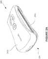
- FIGS. 2A and 2Billustrate a perspective view and a side view, respectively, of a external portable defibrillator 200.
- the defibrillator 200includes two defibrillator paddles 202a and 202b that are mounted over one another and directly scaled together to form a paddle module 204.
- the paddles 202a and 202bmay be pulled apart, which reveals a connecting structure 206, as seen as FIG. 2B , which physically and electrically connects the paddles.
- the connecting structure 206may include a sheet-like portion 207 with instructions that help a user operate the defibrillator 200.
- the paddles 202a and 202bare directly sealed together with a frangible seal. That is, when the paddles 202a and 202b are first pulled apart from one another, the seal is irreversibly and permanently deformed. This feature can have several useful applications. A deformed seal helps indicate whether the paddles 202a and 202b have been used before, which in turn helps indicate whether they are sterile or have sufficient power. Additionally, various events may be triggered by the breaking of the seal.
- one or more capacitors in the defibrillator 200may start charging without requiring additional input from the user (i.e., a button or other mechanical switch need not be separately triggered to power up the defibrillator.)
- personal data of the owner of the defibrillator 200 and/or GPS data indicating the location of the defibrillator 200 and/or unique device identification data of the defibrillator 200may be automatically and wirelessly sent to a remote device or server.
- emergency services, medical personnel, family members or other important entities or individualscan be informed automatically and immediately about the use of the defibrillator.
- the connecting structure 206may serve the dual purpose of displaying useful information as well as electrically connecting the paddles 202a and 202b.
- paddles or patchesare individually connected to a base unit with cables. Instructions are typically displayed on the base unit. The base unit and its display, however, take up considerable space in such systems.
- at least some of the instructionsare provided on a flexible connecting structure 206 that is compressed between the paddles 202a and 202b when the paddle module 204 is sealed. When the paddle module 204 and the paddles 202a and 202b are pulled apart, the connecting structure 206 unfolds or otherwise decompresses and extends between the paddles 202a and 202b.
- the connecting structure 206is attached to the defibrillator paddles 202a and 202b such that it is easily viewable and can be used as an instructional tool while the user is operating the defibrillator.
- each defibrillator paddle 202ahas a defibrillator electrode with an electrically conductive contact surface 203.
- high voltagemay be applied at the contact surfaces 203 to deliver an electrical shock.
- Each sheet-like section 207 of the connecting structure 206includes a top surface 209a and an opposing bottom surface 209b.
- the top surface 209amay include images, light emitting devices, light reflecting devices, display screens, electronic display devices, etc. that help instruct the user in the proper operation of the defibrillator.
- the portability of the defibrillator 200may be enhanced by incorporating some or all of the electrical system of the defibrillator into the paddle module 204. While some implementations involve connecting the paddle module 204 via a cable to an external power module, various other approaches involve placing all of the capacitors and batteries of the defibrillator 200 within the housings of the paddles 202a and 202b. Such designs may free the two paddles 202a and 202b from having to connect with a separate third device, which may help make the defibrillator 200 more convenient to carry, access and operate.
- the overall volume of the defibrillator 200is influenced by the capacity of its electrical system.
- a defibrillator that is capable of delivering more shocks and charging the capacitors more timesgenerally has more and/or larger batteries. More specifically, a larger battery can typically support a greater number of electrical shocks than a smaller one before requiring replacement or recharging.
- existing AEDshave the capacity to deliver many shocks e.g., at least 50 shocks or many more than are typically needed to treat a single cardiac arrest victim.
- each paddlehas a set of conductive protrusions 210 that extend out of each defibrillator paddle 202a and 202b.
- the conductive protrusions 210are coupled with the electrical system of the defibrillator 200.
- the electrical systemwhich includes one or more batteries and capacitors, may be stored within one or more of the defibrillator paddles 202a and 202b, as shown in FIG. 2A , or in an external power module.
- the conductive protrusions 210are part of the defibrillator electrode in each paddle and are arranged to optimize current flow through a sudden cardiac arrest victim.
- the conductive protrusions 210are arranged to press or penetrate into the skin of the victim. Such pressing or penetration reduces the electrical resistance of the skin (e.g., reduces the patient transthoracic impedance for the purpose of delivering a therapeutic current.) As a result, less voltage needs to be generated at the conductive protrusions 210 to ensure a current sufficient to arrest a cardiac arrhythmia in the victim.
- the corresponding reduction in power requirements for the defibrillator 200may translate into a reduction in size of the electrical system of the defibrillator (e.g., a reduction in the size of its capacitors and/or batteries), which in turn helps enhance the portability of the defibrillator 200.
- the volume of all capacitors in the defibrillator 200may be limited to a total volume of approximately 400 cubic centimeters or less.
- the defibrillator 200is arranged to apply a voltage at the defibrillator electrodes that is never in excess of 1400 volts during the normal operation of the defibrillator. (In comparison, some existing AEDs require the application of much more than 1400 volts to defibrillate a person.)
- the conductive protrusions 210may be, in one embodiment that is described below, a microneedle array.
- the defibrillatormay also use other methods such as electroporation and/or sonophoresis to reduce patient transthoracic impedance for the purpose of delivering a therapeutic current.
- electroporation and/or sonophoresis characteristicsare assessed electronically prior to energy delivery to the subject and those characteristics and how they are assessed are well known in the art.
- Electroporationis typically carried out by high voltage pulses applied to a pair of electrodes, which are applied to a tissue surface. The electric pulses cause the passing ions to perforate the tissue layer, providing new pathways for the passage of substances, both charged and not charged. It must be noted that electroporation does not deliver a charged substance, but rather reduces the resistance to passage of substances into the adjacent tissue. Because it does not provide a needed driving force, it is desirable that electroporation be combined with delivery techniques such as iontophoresis or electrophoresis in order to achieve good penetration.
- SCstratum corneum
- these layerswhich are relatively dry, possess low electrical conductivity and consequently inhibits the electromotive forces of the iontophoretic device.
- electrical currenthas to pass through the deeper layers of the skin, i.e. the lower epidermis and the dermis, thereby, carrying active agents into the deep layers and subsequently, into the systemic circulation.
- improving SC conductivityshould result in more electrical current passing through the SC and consequently, higher delivery of the active electrical impulse to the target organ, in this case, the myocardium, rather than being attenuated through the external layers of the skin.
- Electroporationis the phenomenon in which cell membrane permeability to ions and macromolecules is increased by exposing the cell to short (microsecond to millisecond) high voltage electric field pulses (See, for example, E. Neumann, M. Schaeffer-Ridder, Y. Wang, P. H. Hofschneider, Gene transfer into mouse lymphoma cells by electroporation in high electric fields, EMBO J 1 (1982) 841-845 .).
- electrical pulsescan have several different effects on the cell membrane, as a function of various pulse parameters; such as amplitude, length, shape, number of repeats and intervals between pulses.
- the application of the electrical pulsecan have no effect, can have a transient permeabilization effect known as reversible electroporation or can cause permanent permeabilization known as irreversible electroporation. Both, reversible and irreversible electroporation have important application in biotechnology and medicine.
- a controlled electroporation systemin order to induce temporary reversible electroporation of the stratum corneum whereby the pores become enlarged and remain open for an extended duration, the system may use high voltage pulses (over 100V) of high frequency over a short duration.
- high voltage pulsesover 100V
- An exampleis 8 pulses of 750V, each of a duration of 100 microseconds over a total period of 1 second.
- pulsestypically have an amplitude of about 10 to 200 kV/cm and a pulse length of one or several hundreds of picoseconds to one or several tens or hundreds of nanoseconds.
- a large voltage exists across the biological barrier(the cell membrane in the first case; the approximately 100 micron lipid bilayer membranes of the SC in the case of the skin), and a greatly diminished electrical resistance occurs across that barrier.
- the resistancereturns to prepulse values, or nearly prepulse values, comprising "reversible electroporation.”
- artificial planar bilayer membranesexhibit irreversible breakdown, and are destroyed so that resistance across the site of the membrane remains at a greatly diminished value.
- cell membranesremain in an open state, with a greatly diminished transmembrane resistance, and the cell is usually killed.
- R skincan remain at values much smaller than the initial, prepulse values.
- This lack of recoveryis often viewed as evidence of damage to electroporated cells, often fatal damage, in the case of the SC lack of recovery is often assumed to be undesirable, even though the SC is a dead tissue.
- a lack of recoverymeans that the adjacent, viable epidermis is exposed through the persistent pathways to the external environment, i.e. some of the protective feature of the skin has been lost.
- the use of large and/or long pulses that cause skin electroporation but with slight or essentially no recovery of R skinis viewed as undesirable.
- ultrasound at a frequency such as 55 kHzis applied to the patients' skin for 5 to 30 seconds using a suitable device such as the Sontra SonoPrep® ultrasonic skin permeation device. The ultrasound is applied until the conductivity feedback threshold is attained.
- the defibrillatormay also use microneedles since very little (if any) pain, local damage, bleeding, or risk of infection is caused by microneedles.
- the researchhas demonstrated that microprobes with cross-sections on the order of tens of micrometers can penetrate living tissue without causing significant trauma.
- the term "trauma”is defined herein as "pain associated with the application of the article of manufacture to the surface of skin, bleeding, bruising, swelling, damage to skin areas, and the like.”
- a microneedle structure 300may include a substrate 302 having an exterior surface.
- the microneedle structure 300may include a plurality of microneedles 303 attached to the substrate 302 and projecting outwardly a distance, d, from the exterior side of the substrate.
- each microneedlemay have a length (equal to d) that ranges from 50 microns to 300 microns and may also have an outer diameter range of 10 microns to 250 microns.
- Each microneedle 303includes a proximate end 303a, a distal end 303b and an outer surface 303c.
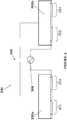
- the microneedle structuremay also have a lower substrate 304 that is gel-like for ECG sensing and to ensure the maximum surface area contact.
- the two paddles 202a, 202bhave the microneedles 303 as well as well known ECG sensing circuit 306 and a defibrillator shock circuit 308 from the capacitor.
- the systemincludes an active electrode assembly, a counter electrode assembly, both of which incorporate a multitude of functionalized microneedles.
- the conductive microneedle arraysare added to the patient facing surface of the electrode pads and are in electrical contact with the device's capacitor, battery and control electronics.
- the microneedleseffectively increase the surface area of the modified electrode pads.
- the electrode padsnow have a 3 dimensional surface area that is significantly larger than the purely two dimensional surface that they previously had. This decreases the current density in the patient's skin and flesh and reduces the likelihood of any tissue damage from the high voltage and current in the defibrillation pulse.
- This increase in surface areacan be further influenced through the use of microneedles with an increased tip area geometry, such as the ZP-Titanium microneedle arrays available from Zosano Pharma. This increases the surface area of the electrode that is directly in contact with the conductive tissues of the deeper epidermis.
- the microneedlesmay or may not be integrally formed from the substrate although they are shown integrally formed with the substrate in Figure 3 .
- the microneedlesmay take a variety of shapes and forms.
- the distal end of the microneedlemay be sharp or dull, and may take a beveled, parabolic, flat-tipped, sharp-tip, blunt-tipped, radius-tipped, chisel-like, tapered and/or tapered-cone-like form.
- the outer shape of the microneedles, including the outer surfacemay take any form including a right cylinder, and oblique cylinder, a circular cylinder, a polygonal cylinder, or any other tapered, regular or irregular shape.
- the microneedlesare provided as a multi-dimensional array, in contrast to a device with a single microneedle or a single row of microneedles.
- the microneedle devicecan be adapted to be a single-use disposable device, or can be adapted to be fully or partially reusable.
- the array of microneedlescan include a mixture of microneedle orientations, heights, or other parameters. Examples of different microneedles are shown in Figures 5-13 .
- Figure 5shows an array of microneedles cut from a conductive sheet in which each microneedle has the same shape
- Figure 6shows an array of microneedles cut from a conductive sheet in which each microneedle has a slightly different shape.
- the larger surface area of the conductive microneedle that penetrates the skin then the larger the effective surface area of the electrodeis which allows the effective patient impedance to be reduced and hence reduces the total amount of energy that needs to be delivered, or else the physical size of the electrode can be reduced.
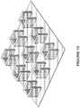
- Figures 7-13illustrate different examples of solid microneedles (since the microneedles can be solid or hollow), such as a cylindrical solid microneedle in Figure 7 , a pyramidal solid microneedle in Figure 8 , a solid pyramidal microneedle with an extended portion to increase the surface area in Figure 9 and an array in Figure 10 , a solid prism shaped microneedle array in Figure 11 , a solid curved blade microneedle array in Figure 12 and a C-channel shaped microneedle array in Figure 13 .
- microneedlesare made by known microfabrication processes by creating small mechanical structures in silicon, metal, polymer, and other materials. These microfabrication processes are based on well-established methods used to make integrated circuits, electronic packages and other microelectronic devices, augmented by additional methods used in the field of micromachining.
- the microneedle devicescan have dimensions as small as a few nanometers and can be mass-produced at low per-unit costs.
- Microfabrication processesthat may be used in making the microneedles disclosed herein include lithography; etching techniques, such as wet chemical, dry, and photoresist removal; thermal oxidation of silicon; electroplating and electrode-less plating; diffusion processes, such as boron, phosphorus, arsenic, and antimony diffusion; ion implantation; film deposition, such as evaporation (filament, electron beam, flash, and shadowing and step coverage), sputtering, chemical vapor deposition (CVD), epitaxy (vapor phase, liquid phase, and molecular beam), electroplating, screen printing, lamination, stereolithography, laser machining, and laser ablation (including projection ablation).
- lithographyetching techniques, such as wet chemical, dry, and photoresist removal
- thermal oxidation of siliconsuch as boron, phosphorus, arsenic, and antimony diffusion
- ion implantationfilm deposition, such as evaporation (filament, electron beam, flash,
- the conductive microneedlesare made from the following range of conductive materials that includes, but is not limited to: metals, ceramics, semiconductors, organics, polymers, and composites.
- the preferred materialsinclude pharmaceutical grade stainless steel, gold, titanium, nickel, iron, gold, platinum, tin, chromium, copper, alloys of these or other metals, silicon, silicon dioxide, capacitive carbon, graphite and polymers.
- the embodimentuses biocompatible materials such as a nickel titanium alloy, titanium, or stainless steel.
- One embodimentincludes microneedles made of metal, such as titanium or stainless steel.
- Metal microneedlesare advantageous because they are durable, semi-flexible, and have the mechanical strength to endure insertion into the stratum corneum, can be cut from readily available, relatively inexpensive commercial stock via a chemical saw, or any suitable technique, to the desired dimensions, and ground to the desired tip geometry.
- the microneedlescan be formed with shafts that have a circular cross-section in the perpendicular, or the cross-section can be non-circular.
- the cross-section of the microneedlecan be polygonal (e.g. star-shaped, square, triangular, circular), oblong, or another symmetrical or asymmetrical shape or even faceted structures including prismatoids, conicals, polyhedrons, pyramids, prisms, wedges and the like.
- the shaftcan have one or more bores.
- the cross-sectional dimensionstypically are between about 10 nm and 1 mm, preferably between 1 micron and 200 microns, and more preferably between 10 and 100 ⁇ m.
- the outer diameteris typically between about 10 microns and about 100 microns.
- a useful outer diameter rangeis from 10-100 microns, and more preferably in the range of 20-50 microns.
- a useful length for useis in the range of 50-1200 microns, and more preferably in the range of 100-400 microns.
- a useful length for useis in the range of 50-1200 microns, and more preferably in the range of 80-400 microns.
- a useful length for useis in the range of 50-1200 microns, and more preferably in the range of 80-400 microns; while the radius of each of its blades is in the range of 10-50 microns, and more preferably in the range of 10-15 microns.
- Other preferred embodimentsinclude methods of maximizing the surface area of the microneedles that are embedded into the skin, such as surface protrusions from the flat sides of a pyramidal shaped microneedle.
- microneedlessuch as those shown in Figures 5-6 , may be pressed or etched out of a sheet of material and then deformed into microprotusions that are at a 90 degree angle from the plane of the sheet. Examples of these microneedles are the ones manufactured by Zosano Pharma and Nano BioSciences.
- the microneedlescan be oriented perpendicular or at another angle to the substrate.
- the microneedlesarc oriented perpendicular to the substrate so that a larger density of microneedles per unit area of substrate is provided.
- an array of microneedlescan include a mixture of microneedle orientations, heights, or other parameters.
- the microneedle arraysmay also have a particular needle density (a number of needle within a particular area.) For example, a useful range of separation distances between microneedles is in the range of 100-1400 microns, and more preferably in the range of 100-400 microns. The outer diameter and microneedle length is also very important, and in combination with the separation distance will be crucial as to whether or not the microneedles will actually penetrate the stratum corneum of skin.
- the microneedle arrayhas a microneedle density of at least approximately 10 microneedles/cm 2 , more preferably, in the range of at least approximately 200-2000 microneedles/cm 2 .
- the microneedle arraysmay be used in conjunction with a conductive hydrogel to ensure maximized surface area of contact.
- Various electrically conductive hydrogelshave been known and used in the medical field to provide an electrical interface to the skin of a subject or within a device to couple electrical stimulus into the subject. Hydrogels hydrate the skin, thus protecting against burning due to electrical stimulation through the hydrogel, while swelling the skin and allowing more efficient transfer of electrical current or signal.
- hydrogelsexamples include US Patent Nos: 6,803,420 ; 6,576,712 ; 6,908,681 ; 6,596,401 ; 6,329,488 ; 6,197,324 ; 5,290,585 ; 6,797,276 ; 5,800,685 ; 5,660,178 ; 5,573,668 ; 5,536,768 ; 5,489,624 ; 5,362,420 ; 5,338,490 ; and 5,240,995 . Further examples of such hydrogels are disclosed in U.S. Patent applications 2004/166147 ; 2004/105834 ; and 2004/247655 .
- hydrogels and hydrogel sheetsinclude CorplexTM by Corium, TegagelTM by 3M, PuraMatrixTM by BD, VigilonTM by Bard, ClearsiteTM by Conmed Corporation, FlexiGelTM by Smith & Nephew, Derma-GelTM by Medline, Nu-GelTM by Johnson & Johnson, and CuragelTM by Kendall, or acrylhydrogel films available from Sun Contact Lens Co., Ltd.
- the substrateas well as other components, are formed from flexible materials to allow the device to fit the contours of the biological barrier, such as the skin to which the device is applied.
- a flexible devicemay facilitate more consistent penetration of some biological barriers, because penetration can be limited by deviations in the attachment surface. For example, the surface of human skin is not flat due to dermatoglyphics (i.e. tiny wrinkles) and hair. However, for some biological barriers, a rigid substrate may be preferred.
- the microneedle devicein another embodiment to adapt to the deformability of skin, includes arrays of microneedles having spaces between the microneedles or between arrays of microneedles, wherein the spacing permit areas of the skin to fill the spaces in order to enhance microneedle contact with adjacent areas of the skin.
- the spacingis designed to adapt to the skin's radius of curvature to overcome the penetration problem.
- the microneedle deviceincludes an adhesive material to secure the microneedle device to the skin, temporarily immobilizing the microneedles while inserted into the skin to deliver the current.
- the adhesive agenttypically is applied to the substrate (in between the microneedles at their base) or to an attachment collar or tabs adjacent the microneedles.
- the defibrillatormay have an impedance sensor having an electrode positioned to measure the impedance of a portion of the target area between the needle and the electrode, the impedance being indicative of the depth of penetration of the needle into the target area.
- the impedance sensorwhich measures the impedance of a portion of the target area between two of the at least two needles when the two needles have penetrated into the target area, the impedance being indicative of the depth of penetration of the needles into the target area.
- the measured impedance after the needle penetrates the skinis an order of magnitude less than the measured impedance before the needle penetrates the skin, and, in particular embodiments, the impedance drops by over three orders of magnitude when the needle has penetrated to the proper depth.
- the applicatoruses the impedance sensor to determine when the stratum corneum has been transversed.
- the impedance sensormeasures impedance of electric current flow between two of the microneedles. Impedance is high in the stratum corneum, and drops dramatically in the portion of the dermis just below the stratum corneum.
- the sensorreads the change in impedance as the microneedles penetrate into the skin, and movement is stopped when the impedance drops by an order of magnitude. Additionally or alternatively, there can be a hard mechanical stop, for example, the top of the ports, that prevents the microneedles from penetrating too deeply.
- the impedance sensorsare well known in the art.
- the device packaging of the defibrillatorshould prevent contamination and damage to the microneedles during manufacturing, packaging, storage, shipment and sale before use. It is particularly important that the microneedle device is provided with a removable protective cover or cushion that protects the microneedles from damage.
- a removable protective cover or cushionthat protects the microneedles from damage.
- an adhesive material or gel film used to selectively secure the cover over the microneedlesmay be used.
- the filmis antiseptic, and following removal can serve as a wipe or adhesive strip to prepare the skin surface before insertion of the microneedles.
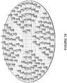
- Figure 14illustrates an example of a defibrillator electrode pad/paddle 202a, 202b with the patient-facing surface covered by a microneedle array
- Figure 15illustrates an example of a defibrillator electrode pad/paddle with an outer circumference of its patient-facing surface covered by a microneedle array and the center without microneedles where electroconductive gel is used to sense the ECG signals from the patient.
- Figure 16illustrates an example of a defibrillator electrode pad/paddle with a majority of the patient-facing surface covered by a microneedle array and the central channels without microneedles where electroconductive gel is used to sense the ECG signals from the patient
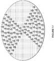
- Figure 17illustrates an example of a defibrillator electrode pad/paddle with the patient-facing surface covered by a microneedle array and regions without microneedles where electroconductive gel is used to sense the ECG signals from the patient.
Landscapes
- Health & Medical Sciences (AREA)
- Life Sciences & Earth Sciences (AREA)
- Public Health (AREA)
- Veterinary Medicine (AREA)
- Biomedical Technology (AREA)
- Nuclear Medicine, Radiotherapy & Molecular Imaging (AREA)
- Radiology & Medical Imaging (AREA)
- Engineering & Computer Science (AREA)
- Animal Behavior & Ethology (AREA)
- General Health & Medical Sciences (AREA)
- Heart & Thoracic Surgery (AREA)
- Cardiology (AREA)
- Dermatology (AREA)
- Physics & Mathematics (AREA)
- Biophysics (AREA)
- Pathology (AREA)
- Medical Informatics (AREA)
- Molecular Biology (AREA)
- Surgery (AREA)
- Electrotherapy Devices (AREA)
Description
- The disclosure relates generally to a device and method for reducing patient transthoracic impedance for the purpose of delivering a therapeutic current in any animal such as human or non-human animal.
- A primary task of the heart is to pump oxygenated, nutrient-rich blood throughout the body. Electrical impulses generated by a portion of the heart regulate the pumping cycle. When the electrical impulses follow a regular and consistent pattern, the heart functions normally and the pumping of blood is optimized. When the electrical impulses of the heart are disrupted (i.e., cardiac arrhythmia), sudden cardiac arrest may result, which inhibits the circulation of blood. As a result, the brain and other critical organs are deprived of nutrients and oxygen. A person experiencing sudden cardiac arrest may suddenly lose consciousness and die shortly thereafter if left untreated.
- A well known and effective treatment for sudden cardiac arrest or arrhythmia is defibrillation or cardioversion. Defibrillation involves passing a current through the person to shock the heart back into a normal rhythm. There arc a wide variety of defibrillators. For example, implantable cardioverter-defibrillators (ICD) involve surgically implanting wire coils and a generator device within a person. ICDs are typically for people at high risk for a cardiac arrhythmia. When a cardiac arrhythmia is detected, a current is automatically passed through the heart of the user with little or no intervention by a third party.
- Another, more common type of defibrillator is the automated external defibrillator (AED). Rather than being implanted, the AED is an external device used by a third party to resuscitate a person who has suffered from sudden cardiac arrest.
FIG. 1 illustrates aconventional AED 100, which includes abase unit 102 and twopads 104. Sometimes paddles with handles are used instead of thepads 104. Thepads 104 are connected to thebase unit 102 usingelectrical cables 106. - A typical protocol for using the AED 100 is as follows. Initially, the person who has suffered from sudden cardiac arrest is placed on the floor. Clothing is removed to reveal the person's
chest 108. Thepads 104 are applied to appropriate locations on thechest 108, as illustrated inFIG. 1 . The electrical system within thebase unit 102 generates a high voltage between the twopads 104, which delivers an electrical shock to the person. Ideally, the shock restores a normal cardiac rhythm. In some cases, multiple shocks are required. - Although existing technologies work well, there are continuing efforts to improve the effectiveness, safety and usability of automatic external defibrillators. For example, if the electrical resistance of the patient can be lowered, then it would be possible to have a defibrillator that requires less power, but effectively delivers the therapeutic current to shock the heart.
- Currently the main mechanism available to reduce the patient impedance is to increase the size of the electrode pads. The larger the surface area of the electrode pads, then the lower the patient impedance that the defibrillator faces. In addition these electrode pads make use of conductive hydrogel to help ensure that as much of each electrode is in conductive contact with the patient's skin as possible.
US 2010/241181 A1 describes a variety of arrangements and methods relating to a defibrillator. In one aspect of the invention, a defibrillator includes two paddles that each include a defibrillator electrode covered in a protective housing. The two paddles are sealed together using a releasable seal to form a paddle module such that the housings of the paddles form the exterior of the paddle module. An electrical system including at least a battery and a capacitor is electrically coupled with the paddles. The battery is arranged to charge the capacitor. The capacitor is arranged to apply a voltage at the defibrillator electrodes, which generates an electrical shock for arresting a cardiac arrhythmia.US 6 256 533 B1 provides a microneedle array, constructed of silicon and silicon dioxide compounds or of a molded plastic material to penetrate the stratum corneum and epidermis layers of skin, but not into the dermis. The microneedles can be used to either dispense a liquid drug, or to sample a body fluid. The delivery of drugs and sampling of fluids can be performed by way of passive diffusion (time release), instantaneous injection, or iontophoresis. A complete closed-loop system can be manufactured including active elements, such as micro-machined pumps, as well as passive elements such as sensors. A "smart patch" can thereby be fabricated that samples body fluids, performs chemistry to decide on the appropriate drug dosage, and then administers the corresponding amount of drug. An electric field may be used to increase transdermal flow rate. Such a system can be made disposable, and can be used with medical devices to dispense drugs by iontophoretic/microneedle enhancement, to sample body fluids (while providing an iontophoretically/microneedle-enhanced body-fluid sensor), and as a closed-loop drug delivery system with fluid sampling feedback using a combination of the other two devices. As a drug dispensing system, the microneedle array includes electrodes that apply an electric potential to the skin between the electrode locations. One of the electrode assemblies is filled with an ionized drug, and the charged drug molecules move into the body due to the applied electric potential. As a body-fluid sampling system, the microneedle array also includes electrodes to assist in moving fluid from the body into a receiving chamber, and which further includes a bioelectrochemical sensor to measure the concentration of a particular substance.US 2007/135729 A1 describes a medical apparatus for diagnosing of a diseased condition of the skin of a subject. The apparatus comprises an electrically conducting probe including a plurality of electrodes, each electrode comprising a plurality of micro-needles, wherein each electrode comprises a base substrate, said micro-needles being integrally formed with said substrate and arranged in a laterally spaced relationship apart from each other and having a length being sufficient to penetrate the stratum corneum, said micro-needles being arranged with an at least partially oblique shape. Furthermore, the present invention relates to an electrode for use in the device, arrays of micro-needle and method for the diagnostics of biological conditions using impedance measurements. The diagnostics is in particular related to cancer, and preferably skin cancer, wherein skin cancer is a basal cell carcinoma, a malignant melanoma, a squamous cell carcinoma, or precursors of such lesions.US 2010/191141 A1 relates to a method and a medical device for diagnosing a diseased condition in tissue of a human or animal subject, wherein tissue electrical impedance measurements are employed. At least one set of data pre-processing rules are applied to impedance of a target tissue region and impedance of a reference tissue region, wherein the reference tissue region is located in close proximity to the target tissue region. The impedance data of the target tissue region and the impedance data of the reference tissue region comprises a plurality of impedance values measured in the target tissue region and the reference tissue region, respectively, wherein the tissue measurements in the two tissue regions are performed substantially concurrently of immediately consecutively. On the basis of the pre-processed data, a trained evaluation system algorithm diagnoses the diseased condition in the target tissue region.- Human skin is the largest organ. Aside from the function of regulating skin temperature, the skin's most important function is to serve as an effective barrier against insult of the body by foreign agents, such as toxic substances, micro-organisms, and due to mechanical injury.
- Skin is the outermost protective layer of the body. It is composed of the epidermis, including the stratum corneum, the stratum granulosum, the stratum spinosum, and the stratum basale, and the dermis, containing, among other things, the capillary layer. Below this is the subcutaneous fat layer. Above the skin, and growing outward from within the skin may be found hair, the strands of which can be up to 100 microns in thickness. Some "durable" skin layers such as heels or calluses, can comprise a stratum corneum which is from 100-150 microns thick.
- The stratum corneum is a tough, scaly layer made of dead cell tissue. It consists of almost laminated layers of keratin from dead cells. It extends around 10-20 microns from the skin surface and has no blood supply. Because of the density of this layer of cells, moving electrical signals, electromagnetic energy or compounds across the skin, either into or out of the body, can be very difficult. Experiments have found the topmost layers of the stratum corneum to be the most resistant.
- The epidermis is typically 50-150 microns in thickness and the dermis, which contains the capillaries and nerve endings is typically 750-1500 microns in thickness. Conductivity of the skin varies by a variety of conditions, such as age, location, sun exposure, use of lotions, moisture level, and ambient conditions, etc.
- Removal of the stratum corneum reduces the high impedance of the skin and allows better transmission and reception of electrical signals, electromagnetic energy or biological species into and from human tissues. It has also been demonstrated that electromagnetic energy induced alterations of the stratum corneum result in increased permeability to substances. Alternatively, compounds commonly referred to as "permeation enhancers" can be used, with some success, to penetrate the stratum corneum. Traditional approaches require the abrasion of skin with sand paper and brushes, the stripping of skin with tape and toxic chemicals, the removal of stratum corneum by laser or thermal ablation, or the puncturing of skin with needles.
- Thus, it is desirable to provide a better way to reduce patient transthoracic impedance for the purpose of delivering a therapeutic current, such as for a defibrillator or cardioverter, and it is to this end that the disclosure is directed.
Figure 1 diagrammatically illustrates an example of a conventional external defibrillator;Figures 2A and2B illustrate a perspective view and a side view, respectively, of a external portable defibrillator;Figures 3 and4 illustrate embodiments of a defibrillator pad with a microneedle array;Figure 5 illustrates an embodiment of a microneedle array;Figure 6 illustrates another embodiment of a microneedle array;Figure 7 illustrates another embodiment of a microneedle array with solid microneedles;Figure 8 illustrates another embodiment of a microneedle array with solid pyramid shaped microneedles;Figure 9 illustrates another embodiment of a microneedle array with solid pyramid shaped microneedles;Figure 10 illustrates another embodiment of a microneedle array with solid pyramid shaped microneedles;Figure 11 illustrates another embodiment of a microneedle array with prism microneedles;Figure 12 illustrates another embodiment of a microneedle array with curved blade microneedles;Figure 13 illustrates another embodiment of a microneedle array with C-channel microneedles;Figure 14 illustrates an example of a defibrillator electrode pad/paddle with the patient-facing surface covered by a microneedle array;Figure 15 illustrates an example of a defibrillator electrode pad/paddle with an outer circumference of its patient-facing surface covered by a microneedle array and the center without microneedles where electroconductive gel is used to sense the ECG signals from the patient;Figure 16 illustrates an example of a defibrillator electrode pad/paddle with a majority of the patient-facing surface covered by a microneedle array and the central channels without microneedles where electroconductive gel is used to sense the ECG signals from the patient;
andFigure 17 illustrates an example of a defibrillator electrode pad/paddle with the patient-facing surface covered by a microneedle array and regions without microneedles where electroconductive gel is used to sense the ECG signals from the patient.- The claimed subject-matter is defined in claim 1. Preferred embodiments are defined in the dependent claims.
- Any disclosed methods are merely exemplary and do not fall within the scope of the present invention. Any example or embodiment which does not fall under the scope of the claims is not part of the invention. The disclosure is particularly applicable to a device and methods for reducing patient transthoracic impedance for the purpose of delivering a therapeutic current in a defibrillator for humans and it is in this context that the disclosure will be described. It will be appreciated, however, that the device and methods for reducing patient transthoracic impedance for the purpose of delivering a therapeutic current has broader applicability to any system in which it is desirable to be able to deliver a therapeutic current and also can be used to deliver a therapeutic current for various purposes and can be used for both humans and animals. To understand the device and methods for reducing patient transthoracic impedance for the purpose of delivering a therapeutic current, an example of a device, a defibrillator, into which the device may be installed, is described.
Figures 2A and2B illustrate a perspective view and a side view, respectively, of a externalportable defibrillator 200. Thedefibrillator 200 includes twodefibrillator paddles paddle module 204. When a need arises to defibrillate a victim of sudden cardiac arrest, thepaddles structure 206, as seen asFIG. 2B , which physically and electrically connects the paddles. The connectingstructure 206 may include a sheet-like portion 207 with instructions that help a user operate thedefibrillator 200.- Preferably, the
paddles paddles paddles defibrillator 200 may start charging without requiring additional input from the user (i.e., a button or other mechanical switch need not be separately triggered to power up the defibrillator.) Upon the opening of thepaddle module 204, personal data of the owner of thedefibrillator 200 and/or GPS data indicating the location of thedefibrillator 200 and/or unique device identification data of thedefibrillator 200 may be automatically and wirelessly sent to a remote device or server. As a result, emergency services, medical personnel, family members or other important entities or individuals can be informed automatically and immediately about the use of the defibrillator. - The connecting
structure 206 may serve the dual purpose of displaying useful information as well as electrically connecting thepaddles structure 206 that is compressed between thepaddles paddle module 204 is sealed. When thepaddle module 204 and thepaddles structure 206 unfolds or otherwise decompresses and extends between thepaddles - The connecting
structure 206 is attached to thedefibrillator paddles defibrillator paddle 202a has a defibrillator electrode with an electricallyconductive contact surface 203. At the appropriate time, high voltage may be applied at the contact surfaces 203 to deliver an electrical shock. Each sheet-like section 207 of the connectingstructure 206 includes atop surface 209a and an opposingbottom surface 209b. Thetop surface 209a may include images, light emitting devices, light reflecting devices, display screens, electronic display devices, etc. that help instruct the user in the proper operation of the defibrillator. As seen inFIG. 2B , when thedefibrillator paddles top surface 209a of the connectingstructure 206 tend to face upward. Thus, a user of the defibrillator may easily reference the connectingstructure 206 for further instructions and step-by-step guidance while holding the defibrillators over the chest of the victim. - In some embodiments, the portability of the
defibrillator 200 may be enhanced by incorporating some or all of the electrical system of the defibrillator into thepaddle module 204. While some implementations involve connecting thepaddle module 204 via a cable to an external power module, various other approaches involve placing all of the capacitors and batteries of thedefibrillator 200 within the housings of thepaddles paddles defibrillator 200 more convenient to carry, access and operate. - Generally, the overall volume of the
defibrillator 200 is influenced by the capacity of its electrical system. A defibrillator that is capable of delivering more shocks and charging the capacitors more times generally has more and/or larger batteries. More specifically, a larger battery can typically support a greater number of electrical shocks than a smaller one before requiring replacement or recharging. As far as the inventors are aware, existing AEDs have the capacity to deliver many shocks e.g., at least 50 shocks or many more than are typically needed to treat a single cardiac arrest victim. - As shown in
Figure 2B , each paddle has a set ofconductive protrusions 210 that extend out of eachdefibrillator paddle conductive protrusions 210 are coupled with the electrical system of thedefibrillator 200. The electrical system, which includes one or more batteries and capacitors, may be stored within one or more of thedefibrillator paddles FIG. 2A , or in an external power module. Theconductive protrusions 210 are part of the defibrillator electrode in each paddle and are arranged to optimize current flow through a sudden cardiac arrest victim. - Generally, the
conductive protrusions 210 are arranged to press or penetrate into the skin of the victim. Such pressing or penetration reduces the electrical resistance of the skin (e.g., reduces the patient transthoracic impedance for the purpose of delivering a therapeutic current.) As a result, less voltage needs to be generated at theconductive protrusions 210 to ensure a current sufficient to arrest a cardiac arrhythmia in the victim. The corresponding reduction in power requirements for thedefibrillator 200 may translate into a reduction in size of the electrical system of the defibrillator (e.g., a reduction in the size of its capacitors and/or batteries), which in turn helps enhance the portability of thedefibrillator 200. In some embodiments, the volume of all capacitors in thedefibrillator 200 may be limited to a total volume of approximately 400 cubic centimeters or less. In still other embodiments, thedefibrillator 200 is arranged to apply a voltage at the defibrillator electrodes that is never in excess of 1400 volts during the normal operation of the defibrillator. (In comparison, some existing AEDs require the application of much more than 1400 volts to defibrillate a person.) Theconductive protrusions 210 may be, in one embodiment that is described below, a microneedle array. - The defibrillator may also use other methods such as electroporation and/or sonophoresis to reduce patient transthoracic impedance for the purpose of delivering a therapeutic current. The electroporation and/or sonophoresis characteristics (as described below) are assessed electronically prior to energy delivery to the subject and those characteristics and how they are assessed are well known in the art.
- The movement of substances, electrical signals or electromagnetic energy transdermally or intradermally may also be aided by a process of electroporation. Electroporation is typically carried out by high voltage pulses applied to a pair of electrodes, which are applied to a tissue surface. The electric pulses cause the passing ions to perforate the tissue layer, providing new pathways for the passage of substances, both charged and not charged. It must be noted that electroporation does not deliver a charged substance, but rather reduces the resistance to passage of substances into the adjacent tissue. Because it does not provide a needed driving force, it is desirable that electroporation be combined with delivery techniques such as iontophoresis or electrophoresis in order to achieve good penetration.
- It is known that the main impediment in the passage of electrical current through the skin is attributed to the dead keratin layers of the stratum corneum (SC). These layers, which are relatively dry, possess low electrical conductivity and consequently inhibits the electromotive forces of the iontophoretic device. As illustrated in all textbooks, because of the high impedance of the stratum corneum, electrical current has to pass through the deeper layers of the skin, i.e. the lower epidermis and the dermis, thereby, carrying active agents into the deep layers and subsequently, into the systemic circulation. Thus, it is understood that improving SC conductivity should result in more electrical current passing through the SC and consequently, higher delivery of the active electrical impulse to the target organ, in this case, the myocardium, rather than being attenuated through the external layers of the skin.
- Electroporation, or electropermeabilization, is the phenomenon in which cell membrane permeability to ions and macromolecules is increased by exposing the cell to short (microsecond to millisecond) high voltage electric field pulses (See, for example,E. Neumann, M. Schaeffer-Ridder, Y. Wang, P. H. Hofschneider, Gene transfer into mouse lymphoma cells by electroporation in high electric fields, EMBO J 1 (1982) 841-845.). Experiments show that the application of electrical pulses can have several different effects on the cell membrane, as a function of various pulse parameters; such as amplitude, length, shape, number of repeats and intervals between pulses. As a function of these parameters, the application of the electrical pulse can have no effect, can have a transient permeabilization effect known as reversible electroporation or can cause permanent permeabilization known as irreversible electroporation. Both, reversible and irreversible electroporation have important application in biotechnology and medicine.
- When electroporation is used to force a current flow across different tissue layers, those with tissue layers with the higher resistivity will be subjected to higher electric fields. Thus, some tissue layers will be more prone to electroporation than others. Since it is possible to reversibly electroporate some tissues while irreversible electroporate others tissues (or burn the tissues) because of a Joule effect, it will be difficult to assess the required external voltage in order to have the sufficient electric field at the region of interest.
- A controlled electroporation system, in order to induce temporary reversible electroporation of the stratum corneum whereby the pores become enlarged and remain open for an extended duration, the system may use high voltage pulses (over 100V) of high frequency over a short duration. An example is 8 pulses of 750V, each of a duration of 100 microseconds over a total period of 1 second. Typically pulses have an amplitude of about 10 to 200 kV/cm and a pulse length of one or several hundreds of picoseconds to one or several tens or hundreds of nanoseconds.
- During a simulating pulse that causes electroporation, a large voltage exists across the biological barrier (the cell membrane in the first case; the approximately 100 micron lipid bilayer membranes of the SC in the case of the skin), and a greatly diminished electrical resistance occurs across that barrier. In many instances, the resistance returns to prepulse values, or nearly prepulse values, comprising "reversible electroporation." For the larger pulses, and for longer pulses, artificial planar bilayer membranes exhibit irreversible breakdown, and are destroyed so that resistance across the site of the membrane remains at a greatly diminished value. Similarly, for the larger pulses, and for longer pulses, cell membranes remain in an open state, with a greatly diminished transmembrane resistance, and the cell is usually killed. In the case of skin, for the larger pulses, and for longer pulses, Rskin can remain at values much smaller than the initial, prepulse values. This lack of recovery is often viewed as evidence of damage to electroporated cells, often fatal damage, in the case of the SC lack of recovery is often assumed to be undesirable, even though the SC is a dead tissue. Further, a lack of recovery means that the adjacent, viable epidermis is exposed through the persistent pathways to the external environment, i.e. some of the protective feature of the skin has been lost. Thus, against the background of artificial planar bilayer membrane electroporation and cell membrane electroporation, the use of large and/or long pulses that cause skin electroporation but with slight or essentially no recovery of Rskin is viewed as undesirable.
- For a controlled sonophoresis system, ultrasound at a frequency such as 55 kHz is applied to the patients' skin for 5 to 30 seconds using a suitable device such as the Sontra SonoPrep® ultrasonic skin permeation device. The ultrasound is applied until the conductivity feedback threshold is attained.
- The defibrillator may also use microneedles since very little (if any) pain, local damage, bleeding, or risk of infection is caused by microneedles. The research has demonstrated that microprobes with cross-sections on the order of tens of micrometers can penetrate living tissue without causing significant trauma. The term "trauma" is defined herein as "pain associated with the application of the article of manufacture to the surface of skin, bleeding, bruising, swelling, damage to skin areas, and the like."
- As shown in
Figure 3 , amicroneedle structure 300 may include asubstrate 302 having an exterior surface. Themicroneedle structure 300 may include a plurality ofmicroneedles 303 attached to thesubstrate 302 and projecting outwardly a distance, d, from the exterior side of the substrate. For example, each microneedle may have a length (equal to d) that ranges from 50 microns to 300 microns and may also have an outer diameter range of 10 microns to 250 microns. Eachmicroneedle 303 includes aproximate end 303a, adistal end 303b and anouter surface 303c. In a defibrillator, the microneedle structure may also have alower substrate 304 that is gel-like for ECG sensing and to ensure the maximum surface area contact. In the defibrillator, the twopaddles microneedles 303 as well as well knownECG sensing circuit 306 and adefibrillator shock circuit 308 from the capacitor. - The system includes an active electrode assembly, a counter electrode assembly, both of which incorporate a multitude of functionalized microneedles. The conductive microneedle arrays are added to the patient facing surface of the electrode pads and are in electrical contact with the device's capacitor, battery and control electronics. The microneedles effectively increase the surface area of the modified electrode pads. The electrode pads now have a 3 dimensional surface area that is significantly larger than the purely two dimensional surface that they previously had. This decreases the current density in the patient's skin and flesh and reduces the likelihood of any tissue damage from the high voltage and current in the defibrillation pulse. This increase in surface area can be further influenced through the use of microneedles with an increased tip area geometry, such as the ZP-Titanium microneedle arrays available from Zosano Pharma. This increases the surface area of the electrode that is directly in contact with the conductive tissues of the deeper epidermis.
- The microneedles may or may not be integrally formed from the substrate although they are shown integrally formed with the substrate in
Figure 3 . The microneedles may take a variety of shapes and forms. For example, the distal end of the microneedle may be sharp or dull, and may take a beveled, parabolic, flat-tipped, sharp-tip, blunt-tipped, radius-tipped, chisel-like, tapered and/or tapered-cone-like form. Furthermore, the outer shape of the microneedles, including the outer surface may take any form including a right cylinder, and oblique cylinder, a circular cylinder, a polygonal cylinder, or any other tapered, regular or irregular shape. Preferably, the microneedles are provided as a multi-dimensional array, in contrast to a device with a single microneedle or a single row of microneedles. The microneedle device can be adapted to be a single-use disposable device, or can be adapted to be fully or partially reusable. The array of microneedles can include a mixture of microneedle orientations, heights, or other parameters. Examples of different microneedles are shown inFigures 5-13 .Figure 5 shows an array of microneedles cut from a conductive sheet in which each microneedle has the same shape whereasFigure 6 shows an array of microneedles cut from a conductive sheet in which each microneedle has a slightly different shape. In this embodiment, the larger surface area of the conductive microneedle that penetrates the skin then the larger the effective surface area of the electrode is which allows the effective patient impedance to be reduced and hence reduces the total amount of energy that needs to be delivered, or else the physical size of the electrode can be reduced.Figures 7-13 illustrate different examples of solid microneedles (since the microneedles can be solid or hollow), such as a cylindrical solid microneedle inFigure 7 , a pyramidal solid microneedle inFigure 8 , a solid pyramidal microneedle with an extended portion to increase the surface area inFigure 9 and an array inFigure 10 , a solid prism shaped microneedle array inFigure 11 , a solid curved blade microneedle array inFigure 12 and a C-channel shaped microneedle array inFigure 13 . - The microneedles are made by known microfabrication processes by creating small mechanical structures in silicon, metal, polymer, and other materials. These microfabrication processes are based on well-established methods used to make integrated circuits, electronic packages and other microelectronic devices, augmented by additional methods used in the field of micromachining. The microneedle devices can have dimensions as small as a few nanometers and can be mass-produced at low per-unit costs. Microfabrication processes that may be used in making the microneedles disclosed herein include lithography; etching techniques, such as wet chemical, dry, and photoresist removal; thermal oxidation of silicon; electroplating and electrode-less plating; diffusion processes, such as boron, phosphorus, arsenic, and antimony diffusion; ion implantation; film deposition, such as evaporation (filament, electron beam, flash, and shadowing and step coverage), sputtering, chemical vapor deposition (CVD), epitaxy (vapor phase, liquid phase, and molecular beam), electroplating, screen printing, lamination, stereolithography, laser machining, and laser ablation (including projection ablation).
- The conductive microneedles (since they need to be able to conduct current) are made from the following range of conductive materials that includes, but is not limited to: metals, ceramics, semiconductors, organics, polymers, and composites. The preferred materials include pharmaceutical grade stainless steel, gold, titanium, nickel, iron, gold, platinum, tin, chromium, copper, alloys of these or other metals, silicon, silicon dioxide, capacitive carbon, graphite and polymers. Ideally the embodiment uses biocompatible materials such as a nickel titanium alloy, titanium, or stainless steel. One embodiment includes microneedles made of metal, such as titanium or stainless steel. Metal microneedles are advantageous because they are durable, semi-flexible, and have the mechanical strength to endure insertion into the stratum corneum, can be cut from readily available, relatively inexpensive commercial stock via a chemical saw, or any suitable technique, to the desired dimensions, and ground to the desired tip geometry.
- In addition to the exemplary microneedles described above, the microneedles can be formed with shafts that have a circular cross-section in the perpendicular, or the cross-section can be non-circular. For example, the cross-section of the microneedle can be polygonal (e.g. star-shaped, square, triangular, circular), oblong, or another symmetrical or asymmetrical shape or even faceted structures including prismatoids, conicals, polyhedrons, pyramids, prisms, wedges and the like. The shaft can have one or more bores. The cross-sectional dimensions typically are between about 10 nm and 1 mm, preferably between 1 micron and 200 microns, and more preferably between 10 and 100 µm. The outer diameter is typically between about 10 microns and about 100 microns.
- For circular solid microneedles, a useful outer diameter range is from 10-100 microns, and more preferably in the range of 20-50 microns. For circular microneedles that do not have sharp edges, a useful length for use is in the range of 50-1200 microns, and more preferably in the range of 100-400 microns. For circular microneedles having sharp side edges, a useful length for use is in the range of 50-1200 microns, and more preferably in the range of 80-400 microns.
- For solid microneedles having a star-shaped profile with sharp edges for its star-shaped blades, a useful length for use is in the range of 50-1200 microns, and more preferably in the range of 80-400 microns; while the radius of each of its blades is in the range of 10-50 microns, and more preferably in the range of 10-15 microns.
- Other preferred embodiments include methods of maximizing the surface area of the microneedles that are embedded into the skin, such as surface protrusions from the flat sides of a pyramidal shaped microneedle.
- The microneedles, such as those shown in
Figures 5-6 , may be pressed or etched out of a sheet of material and then deformed into microprotusions that are at a 90 degree angle from the plane of the sheet. Examples of these microneedles are the ones manufactured by Zosano Pharma and Nano BioSciences. - In most embodiments, the microneedles can be oriented perpendicular or at another angle to the substrate. Preferably, the microneedles arc oriented perpendicular to the substrate so that a larger density of microneedles per unit area of substrate is provided. However, an array of microneedles can include a mixture of microneedle orientations, heights, or other parameters.
- The microneedle arrays may also have a particular needle density (a number of needle within a particular area.) For example, a useful range of separation distances between microneedles is in the range of 100-1400 microns, and more preferably in the range of 100-400 microns. The outer diameter and microneedle length is also very important, and in combination with the separation distance will be crucial as to whether or not the microneedles will actually penetrate the stratum corneum of skin. In one embodiment, the microneedle array has a microneedle density of at least approximately 10 microneedles/cm2, more preferably, in the range of at least approximately 200-2000 microneedles/cm2.
- The microneedle arrays may be used in conjunction with a conductive hydrogel to ensure maximized surface area of contact. Various electrically conductive hydrogels have been known and used in the medical field to provide an electrical interface to the skin of a subject or within a device to couple electrical stimulus into the subject. Hydrogels hydrate the skin, thus protecting against burning due to electrical stimulation through the hydrogel, while swelling the skin and allowing more efficient transfer of electrical current or signal.
- Examples of hydrogels are disclosed in
US Patent Nos: 6,803,420 ;6,576,712 ;6,908,681 ;6,596,401 ;6,329,488 ;6,197,324 ;5,290,585 ;6,797,276 ;5,800,685 ;5,660,178 ;5,573,668 ;5,536,768 ;5,489,624 ;5,362,420 ;5,338,490 ; and5,240,995 . Further examples of such hydrogels are disclosed inU.S. Patent applications 2004/166147 ;2004/105834 ; and2004/247655 . Product brand names of various hydrogels and hydrogel sheets include Corplex™ by Corium, Tegagel™ by 3M, PuraMatrix™ by BD, Vigilon™ by Bard, Clearsite™ by Conmed Corporation, FlexiGel™ by Smith & Nephew, Derma-Gel™ by Medline, Nu-Gel™ by Johnson & Johnson, and Curagel™ by Kendall, or acrylhydrogel films available from Sun Contact Lens Co., Ltd. - In one embodiment of the device, the substrate, as well as other components, are formed from flexible materials to allow the device to fit the contours of the biological barrier, such as the skin to which the device is applied. A flexible device may facilitate more consistent penetration of some biological barriers, because penetration can be limited by deviations in the attachment surface. For example, the surface of human skin is not flat due to dermatoglyphics (i.e. tiny wrinkles) and hair. However, for some biological barriers, a rigid substrate may be preferred.
- In another embodiment to adapt to the deformability of skin, the microneedle device includes arrays of microneedles having spaces between the microneedles or between arrays of microneedles, wherein the spacing permit areas of the skin to fill the spaces in order to enhance microneedle contact with adjacent areas of the skin. The spacing is designed to adapt to the skin's radius of curvature to overcome the penetration problem.
- In a preferred embodiment, the microneedle device includes an adhesive material to secure the microneedle device to the skin, temporarily immobilizing the microneedles while inserted into the skin to deliver the current. The adhesive agent typically is applied to the substrate (in between the microneedles at their base) or to an attachment collar or tabs adjacent the microneedles.
- The defibrillator may have an impedance sensor having an electrode positioned to measure the impedance of a portion of the target area between the needle and the electrode, the impedance being indicative of the depth of penetration of the needle into the target area. The impedance sensor which measures the impedance of a portion of the target area between two of the at least two needles when the two needles have penetrated into the target area, the impedance being indicative of the depth of penetration of the needles into the target area. In some embodiments, the measured impedance after the needle penetrates the skin is an order of magnitude less than the measured impedance before the needle penetrates the skin, and, in particular embodiments, the impedance drops by over three orders of magnitude when the needle has penetrated to the proper depth.
- As stratum corneum depth varies, the applicator uses the impedance sensor to determine when the stratum corneum has been transversed. The impedance sensor measures impedance of electric current flow between two of the microneedles. Impedance is high in the stratum corneum, and drops dramatically in the portion of the dermis just below the stratum corneum. The sensor reads the change in impedance as the microneedles penetrate into the skin, and movement is stopped when the impedance drops by an order of magnitude. Additionally or alternatively, there can be a hard mechanical stop, for example, the top of the ports, that prevents the microneedles from penetrating too deeply. The impedance sensors are well known in the art.
- The device packaging of the defibrillator should prevent contamination and damage to the microneedles during manufacturing, packaging, storage, shipment and sale before use. It is particularly important that the microneedle device is provided with a removable protective cover or cushion that protects the microneedles from damage. In one embodiment, an adhesive material or gel film used to selectively secure the cover over the microneedles may be used. In an alternate embodiment, the film is antiseptic, and following removal can serve as a wipe or adhesive strip to prepare the skin surface before insertion of the microneedles.
Figure 14 illustrates an example of a defibrillator electrode pad/paddle Figure 15 illustrates an example of a defibrillator electrode pad/paddle with an outer circumference of its patient-facing surface covered by a microneedle array and the center without microneedles where electroconductive gel is used to sense the ECG signals from the patient.Figure 16 illustrates an example of a defibrillator electrode pad/paddle with a majority of the patient-facing surface covered by a microneedle array and the central channels without microneedles where electroconductive gel is used to sense the ECG signals from the patient andFigure 17 illustrates an example of a defibrillator electrode pad/paddle with the patient-facing surface covered by a microneedle array and regions without microneedles where electroconductive gel is used to sense the ECG signals from the patient.- While the foregoing has been with reference to a particular embodiment of the invention, it will be appreciated by those skilled in the art that changes in this embodiment may be made without departing from the principles of the disclosure, the scope of which is defined by the appended claims.
Claims (12)
- A defibrillator, comprising:two paddles for delivering a shock to a patient;each paddle having a microneedle array with two or more rows of conductive microneedles;a device for generating a therapeutic current to deliver the shock to the patient through the two paddles;wherein the microneedle array of the two paddles is adapted to apply a voltage to cause electroporation of a skin surface of the patient and to deliver the shock to the patient through the skin surface;whereby the defibrillator ischaracterized by further comprising:an impedance sensor that is adapted to measure a depth of the microneedles through the skin surface and an impedance between two of the conductive microneedles and is adapted to stop penetration of the microneedles when the impedance drops; anda mechanical stop that is adapted to prevent the microneedles from penetrating the skin of the patient too deeply.
- The defibrillator of claim 1, wherein each microneedle in the microneedle array has the same shape.
- The defibrillator of claim 1, wherein each microneedle in the microneedle array has a different shape.
- The defibrillator of claim 1, wherein each microneedle in the microneedle array has a cylindrical shape.
- The defibrillator of claim 1, wherein each microneedle in the microneedle array has a pyramidal shape.
- The defibrillator of claim 5, wherein each pyramidal shaped microneedle further comprises one or more portions that extend from a surface of the pyramidal shaped microneedle to increase an effective surface area of the pyramidal shaped microneedle.
- The defibrillator of claim 1, wherein each microneedle in the microneedle array has one of a prism shape, a curved blade shape and a C-channel shape.
- The defibrillator of claim 1, wherein each paddle has the microneedle array around an outer circumference of the paddle.
- The defibrillator of claim 1, wherein the microneedle array is a first quadrant of microneedles, a second quadrant of microneedles, a third quadrant of microneedles and a fourth quadrant of microneedles wherein the four quadrants are separated from each other.
- The defibrillator of claim 1, wherein the microneedle array is at least a first quadrant of microneedles and a second quadrant of microneedles wherein the quadrants are separated from each other.
- The defibrillator of claim 1, wherein each microneedle is constructed from one of a pharmaceutical grade stainless steel, gold, titanium, nickel, iron, gold, platinum, tin, chromium, copper, alloys, silicon, silicon dioxide, capacitive carbon, graphite and polymers.
- The defibrillator of claim 1, wherein each microneedle is constructed from a biocompatible material.
Applications Claiming Priority (2)
| Application Number | Priority Date | Filing Date | Title |
|---|---|---|---|
| US13/312,910US8781576B2 (en) | 2009-03-17 | 2011-12-06 | Device and method for reducing patient transthoracic impedance for the purpose of delivering a therapeutic current |
| PCT/US2012/065712WO2013085702A1 (en) | 2011-12-06 | 2012-11-16 | Device and method for reducing patient transthoracic |
Publications (3)
| Publication Number | Publication Date |
|---|---|
| EP2788075A1 EP2788075A1 (en) | 2014-10-15 |
| EP2788075A4 EP2788075A4 (en) | 2015-07-29 |
| EP2788075B1true EP2788075B1 (en) | 2018-04-25 |
Family
ID=48574774
Family Applications (1)
| Application Number | Title | Priority Date | Filing Date |
|---|---|---|---|
| EP12854632.2ANot-in-forceEP2788075B1 (en) | 2011-12-06 | 2012-11-16 | Device for reducing patient transthoracic impedance |
Country Status (4)
| Country | Link |
|---|---|
| US (1) | US8781576B2 (en) |
| EP (1) | EP2788075B1 (en) |
| JP (1) | JP5894678B2 (en) |
| WO (1) | WO2013085702A1 (en) |
Families Citing this family (171)
| Publication number | Priority date | Publication date | Assignee | Title |
|---|---|---|---|---|
| US20040116969A1 (en) | 2002-08-26 | 2004-06-17 | Owen James M. | Pulse detection using patient physiological signals |
| US8615295B2 (en)* | 2009-03-17 | 2013-12-24 | Cardiothrive, Inc. | External defibrillator |
| JP6096125B2 (en)* | 2011-01-27 | 2017-03-15 | コーニンクレッカ フィリップス エヌ ヴェKoninklijke Philips N.V. | Defibrillator paddle with lit shock button |
| US9237858B2 (en) | 2011-02-09 | 2016-01-19 | West Affum Holdings Corp. | Detecting loss of full skin contact in patient electrodes |
| EP2570153B1 (en) | 2011-09-14 | 2017-09-13 | NeuroNexus Technologies, Inc. | Methods for forming an electrode device with reduced impedance |
| WO2013071309A1 (en) | 2011-11-11 | 2013-05-16 | The Regents Of The University Of California | Transcutaneous spinal cord stimulation: noninvasive tool for activation of locomotor circuitry |
| US8929980B2 (en) | 2012-05-03 | 2015-01-06 | Physio-Control, Inc. | External defibrillator electrode, method and system for reducing ECG artifact |
| DE102012014653A1 (en)* | 2012-07-24 | 2014-01-30 | Edelgard Liebl | Device for the treatment of the skin |
| US20140043149A1 (en) | 2012-08-10 | 2014-02-13 | Physio-Control, Inc | Mobile communication device & app for wearable defibrillator system |
| US10155110B2 (en) | 2012-08-10 | 2018-12-18 | West Affum Holdings Corp. | Controlling functions of wearable cardiac defibrillation system |
| US9604070B2 (en) | 2012-10-10 | 2017-03-28 | West Affum Holdings Corp. | External defibrillation with automatic post-shock anti-tachycardia (APSAT) pacing |
| US9345898B2 (en) | 2013-01-23 | 2016-05-24 | West Affum Holdings Corp. | Wearable cardiac defibrillator system controlling conductive fluid deployment |
| US9895548B2 (en) | 2013-01-23 | 2018-02-20 | West Affum Holdings Corp. | Wearable cardiac defibrillator (WCD) system controlling conductive fluid deployment per impedance settling at terminal value |
| US10543377B2 (en) | 2013-02-25 | 2020-01-28 | West Affum Holdings Corp. | Wearable cardioverter defibrillator (WCD) system making shock/no shock determinations by aggregating aspects of patient parameters |
| US9757579B2 (en) | 2013-02-25 | 2017-09-12 | West Affum Holdings Corp. | Wearable cardioverter defibrillator (WCD) system informing patient that it is validating just-detected cardiac arrhythmia |
| US12097379B2 (en) | 2013-02-25 | 2024-09-24 | West Affum Holdings Dac | Wearable cardioverter defibrillator (WCD) system making shock/no shock determinations from multiple patient parameters |
| US10500403B2 (en) | 2013-02-25 | 2019-12-10 | West Affum Holdings Corp. | WCD system validating detected cardiac arrhythmias thoroughly so as to not sound loudly due to some quickly self-terminating cardiac arrhythmias |
| US9700221B2 (en)* | 2013-03-06 | 2017-07-11 | Axion Biosystems, Inc. | Non-invasive segmentable three-dimensional microelectrode array patch for neurophysiological diagnostics and therapeutic stimulation |
| WO2014144785A1 (en) | 2013-03-15 | 2014-09-18 | The Regents Of The University Of California | Multi-site transcutaneous electrical stimulation of the spinal cord for facilitation of locomotion |
| US10016613B2 (en) | 2013-04-02 | 2018-07-10 | West Affum Holdings Corp. | Wearable cardiac defibrillator system long-term monitoring alternating patient parameters other than ECG |
| US9827431B2 (en) | 2013-04-02 | 2017-11-28 | West Affum Holdings Corp. | Wearable defibrillator with no long-term ECG monitoring |
| US9907970B2 (en) | 2013-06-14 | 2018-03-06 | Cardiothrive, Inc. | Therapeutic system and method using biphasic or multiphasic pulse waveform |
| US10279189B2 (en) | 2013-06-14 | 2019-05-07 | Cardiothrive, Inc. | Wearable multiphasic cardioverter defibrillator system and method |
| US9656094B2 (en) | 2013-06-14 | 2017-05-23 | Cardiothrive, Inc. | Biphasic or multiphasic pulse generator and method |
| US9616243B2 (en) | 2013-06-14 | 2017-04-11 | Cardiothrive, Inc. | Dynamically adjustable multiphasic defibrillator pulse system and method |
| US10149973B2 (en) | 2013-06-14 | 2018-12-11 | Cardiothrive, Inc. | Multipart non-uniform patient contact interface and method of use |
| US9833630B2 (en) | 2013-06-14 | 2017-12-05 | Cardiothrive, Inc. | Biphasic or multiphasic pulse waveform and method |
| US10137299B2 (en) | 2013-09-27 | 2018-11-27 | The Regents Of The University Of California | Engaging the cervical spinal cord circuitry to re-enable volitional control of hand function in tetraplegic subjects |
| PL3082634T3 (en)* | 2013-12-18 | 2021-10-18 | Novoxel Ltd. | Devices for tissue vaporization |
| US9393437B2 (en) | 2014-04-02 | 2016-07-19 | West Affum Holdings Corp. | Pressure resistant conductive fluid containment |
| US20150306377A1 (en)* | 2014-04-28 | 2015-10-29 | John W. Brantigan | Portable cardiac defibrillators with subcutaneous electrodes and associated systems and methods |
| US10449370B2 (en) | 2014-05-13 | 2019-10-22 | West Affum Holdings Corp. | Network-accessible data about patient with wearable cardiac defibrillator system |
| WO2016103245A1 (en)* | 2014-07-24 | 2016-06-30 | Sasi Solomon | Device and methods for delivery of stimulation to a body tissue |
| WO2016029159A2 (en) | 2014-08-21 | 2016-02-25 | The Regents Of The University Of California | Regulation of autonomic control of bladder voiding after a complete spinal cord injury |
| AU2015308779B2 (en) | 2014-08-27 | 2020-06-25 | The Regents Of The University Of California | Multi-electrode array for spinal cord epidural stimulation |
| US11540762B2 (en) | 2014-10-30 | 2023-01-03 | West Affum Holdings Dac | Wearable cardioverter defibrtillator with improved ECG electrodes |
| US9833607B2 (en) | 2014-10-30 | 2017-12-05 | West Affum Holdings Corp. | Wearable cardiac defibrillation system with flexible electrodes |
| WO2016141096A1 (en)* | 2015-03-03 | 2016-09-09 | Old Dominion University | Low-energy defibrillation with nanosecond pulsed electric fields |
| US20190022371A1 (en)* | 2015-08-06 | 2019-01-24 | The Regents Of The University Of California | Electrode array for transcutaneous electrical stimulation of the spinal cord and uses thereof |
| US11298533B2 (en) | 2015-08-26 | 2022-04-12 | The Regents Of The University Of California | Concerted use of noninvasive neuromodulation device with exoskeleton to enable voluntary movement and greater muscle activation when stepping in a chronically paralyzed subject |
| US10105547B2 (en) | 2015-11-02 | 2018-10-23 | West Affum Holdings Corp. | Wearable cardioverter defibrillator (WCD) causing patient's QRS width to be plotted against the heart rate |
| US11097122B2 (en) | 2015-11-04 | 2021-08-24 | The Regents Of The University Of California | Magnetic stimulation of the spinal cord to restore control of bladder and/or bowel |
| US10322291B2 (en) | 2015-12-04 | 2019-06-18 | West Affum Holdings Corp. | Wearable cardioverter defibrillator (WCD) system with isolated patient parameter component |
| US10179246B2 (en) | 2015-12-04 | 2019-01-15 | West Affum Holdings Corp. | Wearable cardioverter defibrillator (WCD) system using security NFC tag for uploading configuration data |
| US10118047B2 (en)* | 2016-01-03 | 2018-11-06 | Igor Abramov | Automatic defibrillation system |
| US10004912B1 (en) | 2016-07-27 | 2018-06-26 | Cardiospark Llc | System and method for diagnosing and treating cardiac arrhythmia |
| US10092767B1 (en) | 2016-08-11 | 2018-10-09 | Cardiospark Llc | System and method for network-enabled automatic electronic defibrillators |
| ES3037878T3 (en) | 2016-09-06 | 2025-10-07 | Biocircuit Tech Inc | Devices for repairing damage to a nerve |
| US11077310B1 (en) | 2016-10-04 | 2021-08-03 | West Affum Holdings Corp. | Wearable cardioverter defibrillator (WCD) system detecting QRS complexes in ECG signal by matched difference filter |
| US10940323B2 (en) | 2016-10-04 | 2021-03-09 | West Affum Holdings Corp. | Wearable cardioverter defibrillator (WCD) with power-saving function |
| US11052241B2 (en) | 2016-11-03 | 2021-07-06 | West Affum Holdings Corp. | Wearable cardioverter defibrillator (WCD) system measuring patient's respiration |
| US11524168B2 (en) | 2016-12-19 | 2022-12-13 | Hearthero, Inc. | Self-contained, connected automated external defibrillator systems and methods of use |
| WO2018119008A1 (en) | 2016-12-19 | 2018-06-28 | EIR Inc. | Automatic external defibrillator device and methods of use |
| US11938333B2 (en) | 2017-01-05 | 2024-03-26 | West Affum Holdings Dac | Detecting walking in a wearable cardioverter defibrillator system |
| CH713342A2 (en)* | 2017-01-05 | 2018-07-13 | Topolsky Ivan | Automated diagnostic and therapeutic device for cardio-metabolic resuscitation, controlled by external defibrillator. |
| US11083906B2 (en) | 2017-01-05 | 2021-08-10 | West Affum Holdings Corp. | Wearable cardioverter defibrillator having adjustable alarm time |
| US11154230B2 (en) | 2017-01-05 | 2021-10-26 | West Affum Holdings Corp. | Wearable cardioverter defibrillator having reduced noise prompts |
| US11400303B2 (en) | 2018-01-05 | 2022-08-02 | West Affum Holdings Corp. | Detecting walking in a wearable cardioverter defibrillator system |
| US10926080B2 (en) | 2017-01-07 | 2021-02-23 | West Affum Holdings Corp. | Wearable cardioverter defibrillator with breast support |
| US11235143B2 (en) | 2017-02-03 | 2022-02-01 | West Affum Holdings Corp. | Wearable cardiac defibrillator systems and methods and software for contacting non-witnessing responders |
| US10967193B2 (en) | 2017-02-03 | 2021-04-06 | West Affum Holdings Corp. | WCD with pacing analgesia |
| US11235154B2 (en) | 2017-02-17 | 2022-02-01 | The University Of British Columbia | Apparatus and methods for maintaining physiological functions |
| US10960220B2 (en) | 2017-03-16 | 2021-03-30 | West Affum Holdings Corp. | Wearable cardioverter defibrillator (WCD) system evaluating its ECG signals for noise according to tall peak counts |
| US10589109B2 (en) | 2017-04-10 | 2020-03-17 | West Affum Holdings Corp. | Wearable cardioverter defibrillator (WCD) system computing patient heart rate by multiplying ECG signals from different channels |
| US10940324B2 (en) | 2017-05-03 | 2021-03-09 | West Affum Holdings Corp. | Wearable cardioverter defibrillator (WCD) system computing heart rate from noisy ECG signal |
| US11311233B2 (en)* | 2017-05-23 | 2022-04-26 | International Business Machines Corporation | Intelligent and disposable device for selective electrical stimulation of apoptosis |
| WO2018217791A1 (en) | 2017-05-23 | 2018-11-29 | The Regents Of The University Of California | Accessing spinal networks to address sexual dysfunction |
| US10946207B2 (en) | 2017-05-27 | 2021-03-16 | West Affum Holdings Corp. | Defibrillation waveforms for a wearable cardiac defibrillator |
| CA3066361A1 (en) | 2017-06-07 | 2018-12-13 | Shifamed Holdings, Llc | Intravascular fluid movement devices, systems, and methods of use |
| AU2017100994B4 (en)* | 2017-06-20 | 2017-12-14 | Cellaed Life Saver Pty Ltd | A portable single use automated external defibrillator device |
| EP3974021B1 (en) | 2017-06-30 | 2023-06-14 | ONWARD Medical N.V. | A system for neuromodulation |
| US11364387B2 (en) | 2017-07-28 | 2022-06-21 | West Affum Holdings Corp. | Heart rate calculator with reduced overcounting |
| US10737104B2 (en) | 2017-07-28 | 2020-08-11 | West Affum Holdings Corp. | WCD system outputting human-visible indication and proximate programming device with screen reproducing the human-visible indication in real time |
| US11103717B2 (en) | 2017-07-28 | 2021-08-31 | West Affum Holdings Corp. | Wearable cardioverter defibrillator (WCD) system reacting to high-frequency ECG noise |
| US10918879B2 (en) | 2017-07-28 | 2021-02-16 | West Affum Holdings Corp. | Wearable cardioverter defibrillator (WCD) system reacting to high-amplitude ECG noise |
| US11207538B2 (en) | 2017-09-12 | 2021-12-28 | West Affum Holdings Corp. | Wearable cardioverter defibrillator (WCD) system warning ambulatory patient by weak alerting shock |
| US11260237B1 (en) | 2017-11-09 | 2022-03-01 | West Affum Holdings Corp. | Wearable defibrillator with output stage having diverting resistance |
| US11844954B2 (en) | 2017-11-09 | 2023-12-19 | West Affum Holdings Dac | WCD monitor supporting serviceability and reprocessing |
| US11065463B2 (en) | 2017-11-10 | 2021-07-20 | West Affum Holdings Corp. | Wearable cardioverter defibrillator (WCD) system having WCD mode and also AED mode |
| WO2019094963A1 (en) | 2017-11-13 | 2019-05-16 | Shifamed Holdings, Llc | Intravascular fluid movement devices, systems, and methods of use |
| US11058885B2 (en) | 2017-11-29 | 2021-07-13 | West Affum Holdings Corp. | Wearable cardioverter defibrillator (WCD) system detecting ventricular tachycardia and/or ventricular fibrillation using variable heart rate decision threshold |
| US11278730B2 (en) | 2017-12-04 | 2022-03-22 | West Affum Holdings Corp. | Wearable cardioverter defibrillator (WCD) system making shock/no shock determinations from patient's rotational motion |
| US12357828B2 (en) | 2017-12-05 | 2025-07-15 | Ecole Polytechnique Federale De Lausanne (Epfl) | System for planning and/or providing neuromodulation |
| WO2019110400A1 (en) | 2017-12-05 | 2019-06-13 | Ecole Polytechnique Federale De Lausanne (Epfl) | A system for planning and/or providing neuromodulation |
| US10828500B2 (en) | 2017-12-22 | 2020-11-10 | Cardiothrive, Inc. | External defibrillator |
| CN112004563B (en) | 2018-02-01 | 2024-08-06 | 施菲姆德控股有限责任公司 | Intravascular blood pump and methods of use and manufacture |
| US11865354B1 (en) | 2018-02-14 | 2024-01-09 | West Affum Holdings Dac | Methods and systems for distinguishing VT from VF |
| US11160990B1 (en) | 2018-02-14 | 2021-11-02 | West Affum Holdings Corp. | Wearable cardioverter defibrillator (WCD) alarms |
| US12179032B2 (en) | 2018-02-14 | 2024-12-31 | West Affum Holdings Dac | Wearable cardioverter defibrillator (WCD) segment based episode opening and confirmation periods |
| US11471693B1 (en) | 2018-02-14 | 2022-10-18 | West Affum Holdings Dac | Wearable cardioverter defibrillator (WCD) system choosing to consider ECG signals from different channels per QRS complex widths of the ECG signals |
| US11724116B2 (en) | 2018-02-15 | 2023-08-15 | West Affum Holdings Dac | Wearable cardioverter defibrillator latching connector |
| US11040214B2 (en) | 2018-03-01 | 2021-06-22 | West Affum Holdings Corp. | Wearable cardioverter defibrillator (WCD) system having main UI that conveys message and peripheral device that amplifies the message |
| US11000691B2 (en) | 2018-04-24 | 2021-05-11 | West Affum Holdings Corp. | Substantially-median-based determination of long-term heart rates from ECG data of wearable cardioverter defibrillator (WCD) system |
| US11298556B2 (en) | 2018-04-25 | 2022-04-12 | West Affum Holdings Corp. | WCD user interface response to a change in device orientation |
| US11331508B1 (en) | 2018-04-25 | 2022-05-17 | West Affum Holdings Corp. | Wearable cardioverter defibrillator with a non-invasive blood pressure monitor |
| US11058884B2 (en) | 2018-04-26 | 2021-07-13 | West Affum Holding Corp | Wearable medical (WM) system monitoring ECG signal of ambulatory patient for heart condition |
| US11198015B2 (en) | 2018-04-26 | 2021-12-14 | West Affum Holdings Corp. | Multi-sensory alarm for a wearable cardiac defibrillator |
| US11260238B2 (en) | 2018-04-26 | 2022-03-01 | West Affum Holdings Corp. | Wearable medical device (WMD) implementing adaptive techniques to save power |
| US11534615B2 (en) | 2018-04-26 | 2022-12-27 | West Affum Holdings Dac | Wearable Cardioverter Defibrillator (WCD) system logging events and broadcasting state changes and system status information to external clients |
| US11324960B2 (en) | 2018-04-26 | 2022-05-10 | West Affum Holdings Corp. | Permission-based control of interfacing components with a medical device |
| US11833360B2 (en) | 2018-05-29 | 2023-12-05 | West Affum Holdings Dac | Carry pack for a wearable cardioverter defibrillator |
| WO2020023804A1 (en)* | 2018-07-25 | 2020-01-30 | Microdermics Inc. | Microneedles, apparatus comprising microneedles and methods for using same |
| US12161857B2 (en) | 2018-07-31 | 2024-12-10 | Shifamed Holdings, Llc | Intravascular blood pumps and methods of use |
| EP3603508A1 (en)* | 2018-08-03 | 2020-02-05 | PKvitality | Multi-position capsule |
| US11247041B2 (en) | 2018-08-10 | 2022-02-15 | West Affum Holdings Corp. | Wearable cardioverter defibrillator (WCD) with ECG preamp having active input capacitance balancing |
| WO2020073047A1 (en) | 2018-10-05 | 2020-04-09 | Shifamed Holdings, Llc | Intravascular blood pumps and methods of use |
| DE18205821T1 (en) | 2018-11-13 | 2020-12-24 | Gtx Medical B.V. | CONTROL SYSTEM FOR MOTION RECONSTRUCTION AND / OR RECOVERY FOR A PATIENT |
| US12156688B2 (en) | 2018-12-06 | 2024-12-03 | Solta Medical Ireland Limited | Microblade structure and method of treating tissue |
| US11334826B2 (en) | 2019-01-18 | 2022-05-17 | West Affum Holdings Corp. | WCD system prioritization of alerts based on severity and/or required timeliness of user response |
| EP3695878B1 (en) | 2019-02-12 | 2023-04-19 | ONWARD Medical N.V. | A system for neuromodulation |
| US11063378B2 (en) | 2019-03-07 | 2021-07-13 | West Affum Holdings Corp. | Printed circuit board cable clip for signal sensitive applications |
| US11191971B2 (en) | 2019-03-07 | 2021-12-07 | West Affum Holdings Corp. | Wearable cardioverter defibrillator (WCD) system with active ECG cable shielding |
| US12300368B1 (en) | 2019-03-07 | 2025-05-13 | West Affum Holdings Dac | Analysis and presentation of aggregated patient and device data within a system that includes a medical device |
| US12121329B2 (en) | 2019-03-08 | 2024-10-22 | West Affum Holdings Dac | Wearable vital signs monitor with selective signal acquisition |
| US12262976B2 (en) | 2019-03-13 | 2025-04-01 | Blossom Innovations Llc | Devices, systems and methods for tissue analysis, location determination and therapy thereof using optical radiation |
| US11432733B2 (en) | 2019-03-13 | 2022-09-06 | Blossom Innovations | Tissue detection devices, systems and methods |
| WO2021011473A1 (en) | 2019-07-12 | 2021-01-21 | Shifamed Holdings, Llc | Intravascular blood pumps and methods of manufacture and use |
| US11654275B2 (en) | 2019-07-22 | 2023-05-23 | Shifamed Holdings, Llc | Intravascular blood pumps with struts and methods of use and manufacture |
| US11793440B2 (en) | 2019-08-09 | 2023-10-24 | West Affum Holdings Dac | Method to detect noise in a wearable cardioverter defibrillator |
| US10957453B2 (en) | 2019-08-15 | 2021-03-23 | West Affum Holdings Corp. | WCD system alert issuance and resolution |
| US11484271B2 (en) | 2019-08-20 | 2022-11-01 | West Affum Holdings Dac | Alert presentation based on ancillary device conditions |
| US11771360B2 (en) | 2019-08-22 | 2023-10-03 | West Affum Holdings Dac | Cardiac monitoring system with normally conducted QRS complex identification |
| US11730418B2 (en) | 2019-08-22 | 2023-08-22 | West Affum Holdings Dac | Cardiac monitoring system with supraventricular tachycardia (SVT) classifications |
| WO2021062265A1 (en) | 2019-09-25 | 2021-04-01 | Shifamed Holdings, Llc | Intravascular blood pump systems and methods of use and control thereof |
| EP4501393A3 (en) | 2019-09-25 | 2025-04-09 | Shifamed Holdings, LLC | Catheter blood pumps and collapsible pump housings |
| US12121713B2 (en) | 2019-09-25 | 2024-10-22 | Shifamed Holdings, Llc | Catheter blood pumps and collapsible blood conduits |
| USD942013S1 (en) | 2019-10-23 | 2022-01-25 | Cellaed Life Saver Pty Ltd | Defibrillator case |
| USD933824S1 (en) | 2019-11-04 | 2021-10-19 | Cellaed Life Saver Pty Ltd | Defibrillator |
| DE19211698T1 (en) | 2019-11-27 | 2021-09-02 | Onward Medical B.V. | Neuromodulation system |
| EP3827875B1 (en) | 2019-11-27 | 2023-07-05 | ONWARD Medical N.V. | Neuromodulation system |
| EP4072650A4 (en) | 2019-12-11 | 2024-01-10 | Shifamed Holdings, LLC | Descending aorta and vena cava blood pumps |
| US11344718B2 (en) | 2019-12-12 | 2022-05-31 | West Affum Holdings Corp. | Multichannel posture dependent template based rhythm discrimination in a wearable cardioverter defibrillator |
| US11717687B2 (en) | 2020-01-06 | 2023-08-08 | West Affum Holdings Dac | Asystole and complete heart block detection |
| US11904176B1 (en) | 2020-01-27 | 2024-02-20 | West Affum Holdings Dac | Wearable defibrillator system forwarding patient information based on recipient profile and/or event type |
| US11679253B2 (en) | 2020-02-16 | 2023-06-20 | West Affum Holdings Dac | Wearable medical device with integrated blood oxygen saturation level device |
| US12337185B1 (en) | 2020-03-14 | 2025-06-24 | West Affum Holdings Designated Activity Company | Detecting shockable polymorphic ventricular tachycardia |
| KR20210116944A (en)* | 2020-03-18 | 2021-09-28 | 삼성전자주식회사 | Wearable electronic device for sensing biometric information |
| US11819704B2 (en) | 2020-08-21 | 2023-11-21 | West Affum Holdings Dac | Positive system alerts |
| US12226219B1 (en) | 2020-08-21 | 2025-02-18 | West Affum Holdings Dac | Detecting nonsustained ventricular tachycardia in a wearable cardioverter defibrillator |
| US12220256B2 (en) | 2020-08-24 | 2025-02-11 | West Affum Holdings Dac | Autonomous event assistant device |
| US12011607B2 (en) | 2020-08-24 | 2024-06-18 | West Affum Holdings Dac | Assistant for garment and wearable device fitting |
| CA201698S (en) | 2020-08-31 | 2022-09-07 | Cellaed Life Saver Pty Ltd | Defibrillator |
| CA201697S (en) | 2020-08-31 | 2022-09-07 | Cellaed Life Saver Pty Ltd | Defibrillator |
| US11819703B2 (en) | 2020-09-17 | 2023-11-21 | West Affum Holdings Dac | Electrocardiogram (ECG) electrode with deposited ink resistive element |
| US12121737B2 (en) | 2020-09-23 | 2024-10-22 | West Affum Holdings Dac | Wearable cardioverter defibrillator system with remote alerts based on proximity |
| US12357838B2 (en) | 2020-09-30 | 2025-07-15 | West Affum Holdings Dac | Wearable cardioverter defibrillator (WCD) system selecting previously identified preferred channel for attempting to detect pacing artifacts |
| EP4228742A4 (en) | 2020-10-14 | 2024-04-03 | HeartHero, Inc. | AUTOMATED EXTERNAL DEFIBRILLATOR SYSTEMS AND METHODS OF USE |
| US12151117B2 (en) | 2020-11-04 | 2024-11-26 | West Affum Holdings Dac | Wearable cardioverter defibrillator system with electrode moisture sensing |
| US11974855B2 (en) | 2020-11-04 | 2024-05-07 | West Affum Holdings Dac | Method for detecting noise levels in ECG signals using a channel consistency threshold |
| US12036416B2 (en) | 2020-11-09 | 2024-07-16 | West Affum Holdings Dac | Wearable cardioverter defibrillator (WCD) system with wireless battery charging |
| US12233253B2 (en) | 2020-11-10 | 2025-02-25 | West Affum Holdings Dac | Wearable cardioverter defibrillator (WCD) with bystander voice interaction |
| US11698385B2 (en) | 2020-11-11 | 2023-07-11 | West Affum Holdings Dac | Walking intensity detection and trending in a wearable cardioverter defibrillator |
| US11793469B2 (en) | 2020-11-17 | 2023-10-24 | West Affum Holdings Dac | Identifying reliable vectors |
| US11950174B2 (en) | 2020-12-02 | 2024-04-02 | West Affum Holdings Dac | Detailed alarm messages and support |
| US11730968B2 (en) | 2020-12-14 | 2023-08-22 | West Affum Holdings Dac | Wearable medical device with temperature managed electrodes |
| US11712573B2 (en) | 2020-12-16 | 2023-08-01 | West Affum Holdings Dac | Managing alerts in a WCD system |
| US12329973B2 (en) | 2020-12-23 | 2025-06-17 | West Affum Holdings Dac | Rhythm sensing during external pacing |
| US12127860B2 (en) | 2021-01-21 | 2024-10-29 | West Affum Holdings Dac | Wearable device network system |
| US12409331B2 (en) | 2021-02-12 | 2025-09-09 | West Affum Holdings Dac | Wearable Cardioverter Defibrillator (WCD) with artificial intelligence features |
| US12172023B2 (en) | 2021-03-05 | 2024-12-24 | West Affum Holdings Dac | Data channel selection and timeline navigation in a cardiac monitoring system |
| US12427302B2 (en) | 2021-03-08 | 2025-09-30 | West Affum Holdings Dac | On-demand remote data acquisition and programming in a wearable medical device |
| US12232879B2 (en) | 2021-06-29 | 2025-02-25 | West Affum Holdings Dac | Atrial fibrillation detection |
| US12296184B2 (en) | 2021-09-22 | 2025-05-13 | West Affum Holdings Dac | Providing wearable device information to rescuers |
| US12311188B2 (en) | 2021-09-22 | 2025-05-27 | West Affum Holdings Dac | Power in a wearable cardioverter defibrillator (WCD) |
| US12362065B2 (en) | 2021-09-23 | 2025-07-15 | West Affum Holdings Dac | Health data management and display |
| US11529526B1 (en) | 2021-12-10 | 2022-12-20 | Hearthero, Inc. | Automated external defibrillator |
| US12354750B2 (en) | 2021-12-22 | 2025-07-08 | West Affum Holdings Dac | Selection of a wearable article for a medical device |
| CN115531727A (en)* | 2022-08-17 | 2022-12-30 | 宝鸡市德尔医疗器械制造有限责任公司 | A portable external miniature defibrillator and mobile phone |
| WO2024075820A1 (en)* | 2022-10-05 | 2024-04-11 | 株式会社オンラインマスター | Automated external defibrillator |
| GB202302529D0 (en)* | 2023-02-22 | 2023-04-05 | Windridge Dale | A defibrillator |
| JP7620356B1 (en) | 2024-01-26 | 2025-01-23 | 株式会社オンラインマスター | Automated External Defibrillator |
Citations (2)
| Publication number | Priority date | Publication date | Assignee | Title |
|---|---|---|---|---|
| US20070135729A1 (en)* | 2005-12-14 | 2007-06-14 | Scibase Ab | Medical apparatus for determination of biological conditions using impedance measurements |
| US20100191141A1 (en)* | 2009-01-27 | 2010-07-29 | Peter Aberg | Method and apparatus for diagnosing a diseased condition in tissue of a subject |
Family Cites Families (58)
| Publication number | Priority date | Publication date | Assignee | Title |
|---|---|---|---|---|
| US5240995A (en) | 1989-02-09 | 1993-08-31 | Alza Corporation | Electrotransport adhesive |
| US5443727A (en) | 1990-10-30 | 1995-08-22 | Minnesota Mining And Manufacturing Company | Articles having a polymeric shell and method for preparing same |
| US5160790A (en) | 1990-11-01 | 1992-11-03 | C. R. Bard, Inc. | Lubricious hydrogel coatings |
| DE4238263A1 (en) | 1991-11-15 | 1993-05-19 | Minnesota Mining & Mfg | Adhesive comprising hydrogel and crosslinked polyvinyl:lactam - is used in electrodes for biomedical application providing low impedance and good mechanical properties when water and/or moisture is absorbed from skin |
| DE69213758T2 (en) | 1991-11-15 | 1997-05-07 | Minnesota Mining & Mfg | BIOMEDICAL ELECTRODE WITH TWO-PHASE CONSTRUCTIVE, SELF-ADHESIVE ADHESIVE |
| US5402884A (en) | 1992-09-24 | 1995-04-04 | Surviva Link Corporation | Medical electrode packaging technology |
| US5643252A (en) | 1992-10-28 | 1997-07-01 | Venisect, Inc. | Laser perforator |
| US6315772B1 (en) | 1993-09-24 | 2001-11-13 | Transmedica International, Inc. | Laser assisted pharmaceutical delivery and fluid removal |
| US5489624A (en) | 1992-12-01 | 1996-02-06 | Minnesota Mining And Manufacturing Company | Hydrophilic pressure sensitive adhesives |
| US5658316A (en) | 1995-07-03 | 1997-08-19 | Automatic Defibrillator, Inc. | Portable defibrillator with disposable power pack |
| US6230051B1 (en)* | 1996-06-18 | 2001-05-08 | Alza Corporation | Device for enhancing transdermal agent delivery or sampling |
| US5800685A (en) | 1996-10-28 | 1998-09-01 | Cardiotronics Systems, Inc. | Electrically conductive adhesive hydrogels |
| US6797276B1 (en) | 1996-11-14 | 2004-09-28 | The United States Of America As Represented By The Secretary Of The Army | Use of penetration enhancers and barrier disruption agents to enhance the transcutaneous immune response |
| US6148233A (en)* | 1997-03-07 | 2000-11-14 | Cardiac Science, Inc. | Defibrillation system having segmented electrodes |
| US6266563B1 (en) | 1997-03-14 | 2001-07-24 | Uab Research Foundation | Method and apparatus for treating cardiac arrhythmia |
| US6197324B1 (en) | 1997-12-18 | 2001-03-06 | C. R. Bard, Inc. | System and methods for local delivery of an agent |
| US6041255A (en) | 1998-04-16 | 2000-03-21 | Kroll; Mark W. | Disposable external defibrillator |
| US6141584A (en) | 1998-09-30 | 2000-10-31 | Agilent Technologies, Inc. | Defibrillator with wireless communications |
| US6596401B1 (en) | 1998-11-10 | 2003-07-22 | C. R. Bard Inc. | Silane copolymer compositions containing active agents |
| US6329488B1 (en) | 1998-11-10 | 2001-12-11 | C. R. Bard, Inc. | Silane copolymer coatings |
| JP4210386B2 (en) | 1999-03-30 | 2009-01-14 | テルモ株式会社 | Intracavitary ultrasound system |
| US6611707B1 (en) | 1999-06-04 | 2003-08-26 | Georgia Tech Research Corporation | Microneedle drug delivery device |
| US6256533B1 (en) | 1999-06-09 | 2001-07-03 | The Procter & Gamble Company | Apparatus and method for using an intracutaneous microneedle array |
| US6379324B1 (en)* | 1999-06-09 | 2002-04-30 | The Procter & Gamble Company | Intracutaneous microneedle array apparatus |
| US20070016268A1 (en) | 2000-01-07 | 2007-01-18 | John Carter | Percutaneous electrode array |
| US6576712B2 (en) | 2000-07-07 | 2003-06-10 | A. V. Topchiev Institute Of Petrochemical Synthesis | Preparation of hydrophilic pressure sensitive adhesives having optimized adhesive properties |
| US6690959B2 (en) | 2000-09-01 | 2004-02-10 | Medtronic, Inc. | Skin-mounted electrodes with nano spikes |
| US6821281B2 (en) | 2000-10-16 | 2004-11-23 | The Procter & Gamble Company | Microstructures for treating and conditioning skin |
| US6662056B2 (en) | 2000-12-22 | 2003-12-09 | Koninklijke Philips Electronics N.V. | Cartridge for storing an electrode pad |
| US6935889B2 (en) | 2001-02-28 | 2005-08-30 | Koninklijke Philips Electronics N.V. | Electrode-pad package that is removable from an electrode-pad lead and method for opening the package |
| US8206738B2 (en) | 2001-05-01 | 2012-06-26 | Corium International, Inc. | Hydrogel compositions with an erodible backing member |
| CA2447302C (en) | 2001-05-01 | 2008-07-29 | A.V. Topchiev Institute Of Petrochemical Synthesis | Two-phase, water-absorbent bioadhesive composition |
| WO2003020362A2 (en) | 2001-08-31 | 2003-03-13 | Access Cardiosystems, Inc. | Automated external defibrillator (aed) system |
| US6714817B2 (en) | 2001-08-31 | 2004-03-30 | Medtronic Physio-Control Manufacturing Corp. | Hard paddle for an external defibrillator |
| US7069074B2 (en) | 2001-11-07 | 2006-06-27 | Medtronic Emergency Response Systems, Inc. | Easy-to-use electrode and package |
| US7429258B2 (en)* | 2001-10-26 | 2008-09-30 | Massachusetts Institute Of Technology | Microneedle transport device |
| US6639381B2 (en) | 2001-10-26 | 2003-10-28 | Medtronic Physio-Control Corp. | Defibrillator with replaceable and rechargeable power packs |
| US6908453B2 (en) | 2002-01-15 | 2005-06-21 | 3M Innovative Properties Company | Microneedle devices and methods of manufacture |
| CA2729967C (en) | 2002-12-13 | 2018-01-16 | Schering-Plough Healthcare Products, Inc. | Use of a transdermal or transmucosal ingredient delivery device |
| US20040143297A1 (en) | 2003-01-21 | 2004-07-22 | Maynard Ramsey | Advanced automatic external defibrillator powered by alternative and optionally multiple electrical power sources and a new business method for single use AED distribution and refurbishment |
| US9278155B2 (en) | 2003-06-05 | 2016-03-08 | 3M Innovative Properties Company | Adhesive compositions, articles incorporating same and methods of manufacture |
| JP2007509704A (en) | 2003-10-31 | 2007-04-19 | アルザ・コーポレーシヨン | Systems and methods for transdermal vaccine delivery |
| WO2005092434A1 (en)* | 2004-03-25 | 2005-10-06 | Koninklijke Philips Electronics, N.V. | Defibrillation electrode having drug delivery capability |
| US7463917B2 (en)* | 2004-04-28 | 2008-12-09 | Medtronic, Inc. | Electrodes for sustained delivery of energy |
| WO2006046160A1 (en) | 2004-10-29 | 2006-05-04 | Koninklijke Philips Electronics, N.V. | Electrode and enclosure for cardiac monitoring and treatment |
| WO2006055936A2 (en) | 2004-11-18 | 2006-05-26 | Access Cardiosystems, Inc. | System and method for performing self-test in an automatic external defibrillator (afd) |
| US20060142806A1 (en) | 2004-12-27 | 2006-06-29 | Koninklijke Philips Electronics N.V. | Method and article for storing an automatic external defibrillator for use without a prescription |
| JP2009509634A (en) | 2005-09-30 | 2009-03-12 | Tti・エルビュー株式会社 | Functionalized microneedle transdermal drug delivery system, apparatus and method |
| US20100168501A1 (en) | 2006-10-02 | 2010-07-01 | Daniel Rogers Burnett | Method and apparatus for magnetic induction therapy |
| US7747319B2 (en) | 2006-03-17 | 2010-06-29 | Zoll Medical Corporation | Automated resuscitation device with ventilation sensing and prompting |
| DE102006025864A1 (en) | 2006-06-02 | 2007-12-06 | Robert Bosch Gmbh | Mobile device e.g. mobile telephone, for recording e.g. electrocardiogram, has defibrillator for inducing electrical potential in patient, and electrodes with needle-like extensions provided to penetrate into top skin layer of patient |
| US8024037B2 (en) | 2006-08-01 | 2011-09-20 | Kumar Uday N | External defibrillator |
| JP2010509006A (en) | 2006-11-15 | 2010-03-25 | ハートサイン テクノロジーズ リミテッド | Disposable external defibrillator |
| EP2061551A2 (en)* | 2006-12-01 | 2009-05-27 | TTI ellebeau, Inc. | Systems, devices, and methods for powering and/or controlling devices, for instance transdermal delivery devices |
| US20080312579A1 (en)* | 2007-06-15 | 2008-12-18 | Transport Pharmaceuticals, Inc. | Method and system for mitigating current concentration in electrokinetic drug delivery |
| JP4955634B2 (en)* | 2008-09-24 | 2012-06-20 | テルモ株式会社 | Drug administration device |
| US8615295B2 (en)* | 2009-03-17 | 2013-12-24 | Cardiothrive, Inc. | External defibrillator |
| JP2011056183A (en)* | 2009-09-14 | 2011-03-24 | Olympus Corp | Medical sheet-like member |
- 2011
- 2011-12-06USUS13/312,910patent/US8781576B2/enactiveActive
- 2012
- 2012-11-16WOPCT/US2012/065712patent/WO2013085702A1/enactiveApplication Filing
- 2012-11-16JPJP2014545921Apatent/JP5894678B2/enactiveActive
- 2012-11-16EPEP12854632.2Apatent/EP2788075B1/ennot_activeNot-in-force
Patent Citations (2)
| Publication number | Priority date | Publication date | Assignee | Title |
|---|---|---|---|---|
| US20070135729A1 (en)* | 2005-12-14 | 2007-06-14 | Scibase Ab | Medical apparatus for determination of biological conditions using impedance measurements |
| US20100191141A1 (en)* | 2009-01-27 | 2010-07-29 | Peter Aberg | Method and apparatus for diagnosing a diseased condition in tissue of a subject |
Also Published As
| Publication number | Publication date |
|---|---|
| US20120310315A1 (en) | 2012-12-06 |
| JP5894678B2 (en) | 2016-03-30 |
| EP2788075A1 (en) | 2014-10-15 |
| WO2013085702A1 (en) | 2013-06-13 |
| JP2015500090A (en) | 2015-01-05 |
| US8781576B2 (en) | 2014-07-15 |
| EP2788075A4 (en) | 2015-07-29 |
Similar Documents
| Publication | Publication Date | Title |
|---|---|---|
| EP2788075B1 (en) | Device for reducing patient transthoracic impedance | |
| US9101778B2 (en) | Device and method for reducing patient transthoracic impedance for the purpose of delivering a therapeutic current | |
| US7315758B2 (en) | Transdermal delivery of therapeutic agent | |
| EP1448263B1 (en) | Device for controlled delivery of active substance into the skin | |
| US8588884B2 (en) | Microneedle electrode | |
| AU2002363106A1 (en) | Device and method for controlled delivery of active substance into the skin | |
| US20060264805A1 (en) | Permeabilization of biological membranes | |
| JP2003529401A (en) | Tissue electroperforation for drug delivery and diagnostic sampling | |
| JP2001157715A (en) | Method and device suitable for skin abrasion | |
| US20090287208A1 (en) | Electrolytic tissue treatment | |
| JP2004523308A (en) | Tissue electroporation for improved drug delivery and diagnostic sampling | |
| JP2010075710A (en) | Dermal patch | |
| JP6751351B2 (en) | Device to inactivate bacteria | |
| US5919156A (en) | Iontophoretic drug delivery system, including unit for dispensing patches | |
| MX2007012982A (en) | Dc tissue treatment. | |
| Banga | New technologies to allow transdermal delivery of therapeutic proteins and small water-soluble drugs | |
| Herwadkar et al. | An update on the application of physical technologies to enhance intradermal and transdermal drug delivery | |
| JP2002282371A (en) | Low voltage drive type ionophoretic element | |
| Angamuthu et al. | Therapeutic applications of electroporation | |
| EP4048373B1 (en) | Continuous or periodical transdermal delivery of exogenous molecule | |
| JP4182555B2 (en) | Iontophoresis element for transdermal administration | |
| Gowrishankar et al. | Transdermal drug delivery by localized intervention | |
| Kwiatkowski et al. | Transdermal delivery of therapeutic agent |
Legal Events
| Date | Code | Title | Description |
|---|---|---|---|
| PUAI | Public reference made under article 153(3) epc to a published international application that has entered the european phase | Free format text:ORIGINAL CODE: 0009012 | |
| 17P | Request for examination filed | Effective date:20140707 | |
| AK | Designated contracting states | Kind code of ref document:A1 Designated state(s):AL AT BE BG CH CY CZ DE DK EE ES FI FR GB GR HR HU IE IS IT LI LT LU LV MC MK MT NL NO PL PT RO RS SE SI SK SM TR | |
| DAX | Request for extension of the european patent (deleted) | ||
| RA4 | Supplementary search report drawn up and despatched (corrected) | Effective date:20150629 | |
| RIC1 | Information provided on ipc code assigned before grant | Ipc:A61B 5/053 20060101ALI20150623BHEP Ipc:A61N 1/05 20060101AFI20150623BHEP Ipc:A61N 1/32 20060101ALI20150623BHEP | |
| 17Q | First examination report despatched | Effective date:20160401 | |
| RIC1 | Information provided on ipc code assigned before grant | Ipc:A61N 1/05 20060101AFI20170918BHEP Ipc:A61N 1/32 20060101ALI20170918BHEP Ipc:A61N 1/39 20060101ALI20170918BHEP Ipc:A61B 5/053 20060101ALI20170918BHEP | |
| GRAP | Despatch of communication of intention to grant a patent | Free format text:ORIGINAL CODE: EPIDOSNIGR1 | |
| INTG | Intention to grant announced | Effective date:20171130 | |
| GRAA | (expected) grant | Free format text:ORIGINAL CODE: 0009210 | |
| GRAS | Grant fee paid | Free format text:ORIGINAL CODE: EPIDOSNIGR3 | |
| AK | Designated contracting states | Kind code of ref document:B1 Designated state(s):AL AT BE BG CH CY CZ DE DK EE ES FI FR GB GR HR HU IE IS IT LI LT LU LV MC MK MT NL NO PL PT RO RS SE SI SK SM TR | |
| REG | Reference to a national code | Ref country code:GB Ref legal event code:FG4D | |
| REG | Reference to a national code | Ref country code:CH Ref legal event code:EP | |
| REG | Reference to a national code | Ref country code:CH Ref legal event code:NV Representative=s name:RENTSCH PARTNER AG, CH Ref country code:AT Ref legal event code:REF Ref document number:992239 Country of ref document:AT Kind code of ref document:T Effective date:20180515 | |
| REG | Reference to a national code | Ref country code:IE Ref legal event code:FG4D | |
| REG | Reference to a national code | Ref country code:DE Ref legal event code:R096 Ref document number:602012045753 Country of ref document:DE | |
| REG | Reference to a national code | Ref country code:NL Ref legal event code:FP | |
| REG | Reference to a national code | Ref country code:SE Ref legal event code:TRGR | |
| REG | Reference to a national code | Ref country code:LT Ref legal event code:MG4D | |
| PG25 | Lapsed in a contracting state [announced via postgrant information from national office to epo] | Ref country code:NO Free format text:LAPSE BECAUSE OF FAILURE TO SUBMIT A TRANSLATION OF THE DESCRIPTION OR TO PAY THE FEE WITHIN THE PRESCRIBED TIME-LIMIT Effective date:20180725 Ref country code:FI Free format text:LAPSE BECAUSE OF FAILURE TO SUBMIT A TRANSLATION OF THE DESCRIPTION OR TO PAY THE FEE WITHIN THE PRESCRIBED TIME-LIMIT Effective date:20180425 Ref country code:BG Free format text:LAPSE BECAUSE OF FAILURE TO SUBMIT A TRANSLATION OF THE DESCRIPTION OR TO PAY THE FEE WITHIN THE PRESCRIBED TIME-LIMIT Effective date:20180725 Ref country code:PL Free format text:LAPSE BECAUSE OF FAILURE TO SUBMIT A TRANSLATION OF THE DESCRIPTION OR TO PAY THE FEE WITHIN THE PRESCRIBED TIME-LIMIT Effective date:20180425 Ref country code:LT Free format text:LAPSE BECAUSE OF FAILURE TO SUBMIT A TRANSLATION OF THE DESCRIPTION OR TO PAY THE FEE WITHIN THE PRESCRIBED TIME-LIMIT Effective date:20180425 Ref country code:ES Free format text:LAPSE BECAUSE OF FAILURE TO SUBMIT A TRANSLATION OF THE DESCRIPTION OR TO PAY THE FEE WITHIN THE PRESCRIBED TIME-LIMIT Effective date:20180425 | |
| PG25 | Lapsed in a contracting state [announced via postgrant information from national office to epo] | Ref country code:LV Free format text:LAPSE BECAUSE OF FAILURE TO SUBMIT A TRANSLATION OF THE DESCRIPTION OR TO PAY THE FEE WITHIN THE PRESCRIBED TIME-LIMIT Effective date:20180425 Ref country code:HR Free format text:LAPSE BECAUSE OF FAILURE TO SUBMIT A TRANSLATION OF THE DESCRIPTION OR TO PAY THE FEE WITHIN THE PRESCRIBED TIME-LIMIT Effective date:20180425 Ref country code:RS Free format text:LAPSE BECAUSE OF FAILURE TO SUBMIT A TRANSLATION OF THE DESCRIPTION OR TO PAY THE FEE WITHIN THE PRESCRIBED TIME-LIMIT Effective date:20180425 Ref country code:GR Free format text:LAPSE BECAUSE OF FAILURE TO SUBMIT A TRANSLATION OF THE DESCRIPTION OR TO PAY THE FEE WITHIN THE PRESCRIBED TIME-LIMIT Effective date:20180726 | |
| REG | Reference to a national code | Ref country code:AT Ref legal event code:MK05 Ref document number:992239 Country of ref document:AT Kind code of ref document:T Effective date:20180425 | |
| PG25 | Lapsed in a contracting state [announced via postgrant information from national office to epo] | Ref country code:PT Free format text:LAPSE BECAUSE OF FAILURE TO SUBMIT A TRANSLATION OF THE DESCRIPTION OR TO PAY THE FEE WITHIN THE PRESCRIBED TIME-LIMIT Effective date:20180827 | |
| REG | Reference to a national code | Ref country code:DE Ref legal event code:R097 Ref document number:602012045753 Country of ref document:DE | |
| PG25 | Lapsed in a contracting state [announced via postgrant information from national office to epo] | Ref country code:DK Free format text:LAPSE BECAUSE OF FAILURE TO SUBMIT A TRANSLATION OF THE DESCRIPTION OR TO PAY THE FEE WITHIN THE PRESCRIBED TIME-LIMIT Effective date:20180425 Ref country code:SK Free format text:LAPSE BECAUSE OF FAILURE TO SUBMIT A TRANSLATION OF THE DESCRIPTION OR TO PAY THE FEE WITHIN THE PRESCRIBED TIME-LIMIT Effective date:20180425 Ref country code:CZ Free format text:LAPSE BECAUSE OF FAILURE TO SUBMIT A TRANSLATION OF THE DESCRIPTION OR TO PAY THE FEE WITHIN THE PRESCRIBED TIME-LIMIT Effective date:20180425 Ref country code:RO Free format text:LAPSE BECAUSE OF FAILURE TO SUBMIT A TRANSLATION OF THE DESCRIPTION OR TO PAY THE FEE WITHIN THE PRESCRIBED TIME-LIMIT Effective date:20180425 Ref country code:AT Free format text:LAPSE BECAUSE OF FAILURE TO SUBMIT A TRANSLATION OF THE DESCRIPTION OR TO PAY THE FEE WITHIN THE PRESCRIBED TIME-LIMIT Effective date:20180425 Ref country code:EE Free format text:LAPSE BECAUSE OF FAILURE TO SUBMIT A TRANSLATION OF THE DESCRIPTION OR TO PAY THE FEE WITHIN THE PRESCRIBED TIME-LIMIT Effective date:20180425 | |
| PG25 | Lapsed in a contracting state [announced via postgrant information from national office to epo] | Ref country code:SM Free format text:LAPSE BECAUSE OF FAILURE TO SUBMIT A TRANSLATION OF THE DESCRIPTION OR TO PAY THE FEE WITHIN THE PRESCRIBED TIME-LIMIT Effective date:20180425 | |
| PLBE | No opposition filed within time limit | Free format text:ORIGINAL CODE: 0009261 | |
| STAA | Information on the status of an ep patent application or granted ep patent | Free format text:STATUS: NO OPPOSITION FILED WITHIN TIME LIMIT | |
| 26N | No opposition filed | Effective date:20190128 | |
| PG25 | Lapsed in a contracting state [announced via postgrant information from national office to epo] | Ref country code:SI Free format text:LAPSE BECAUSE OF FAILURE TO SUBMIT A TRANSLATION OF THE DESCRIPTION OR TO PAY THE FEE WITHIN THE PRESCRIBED TIME-LIMIT Effective date:20180425 | |
| PG25 | Lapsed in a contracting state [announced via postgrant information from national office to epo] | Ref country code:MC Free format text:LAPSE BECAUSE OF FAILURE TO SUBMIT A TRANSLATION OF THE DESCRIPTION OR TO PAY THE FEE WITHIN THE PRESCRIBED TIME-LIMIT Effective date:20180425 Ref country code:LU Free format text:LAPSE BECAUSE OF NON-PAYMENT OF DUE FEES Effective date:20181116 | |
| REG | Reference to a national code | Ref country code:BE Ref legal event code:MM Effective date:20181130 | |
| PG25 | Lapsed in a contracting state [announced via postgrant information from national office to epo] | Ref country code:BE Free format text:LAPSE BECAUSE OF NON-PAYMENT OF DUE FEES Effective date:20181130 Ref country code:AL Free format text:LAPSE BECAUSE OF FAILURE TO SUBMIT A TRANSLATION OF THE DESCRIPTION OR TO PAY THE FEE WITHIN THE PRESCRIBED TIME-LIMIT Effective date:20180425 | |
| PG25 | Lapsed in a contracting state [announced via postgrant information from national office to epo] | Ref country code:MT Free format text:LAPSE BECAUSE OF NON-PAYMENT OF DUE FEES Effective date:20181116 | |
| PG25 | Lapsed in a contracting state [announced via postgrant information from national office to epo] | Ref country code:TR Free format text:LAPSE BECAUSE OF FAILURE TO SUBMIT A TRANSLATION OF THE DESCRIPTION OR TO PAY THE FEE WITHIN THE PRESCRIBED TIME-LIMIT Effective date:20180425 | |
| PG25 | Lapsed in a contracting state [announced via postgrant information from national office to epo] | Ref country code:HU Free format text:LAPSE BECAUSE OF FAILURE TO SUBMIT A TRANSLATION OF THE DESCRIPTION OR TO PAY THE FEE WITHIN THE PRESCRIBED TIME-LIMIT; INVALID AB INITIO Effective date:20121116 Ref country code:MK Free format text:LAPSE BECAUSE OF NON-PAYMENT OF DUE FEES Effective date:20180425 Ref country code:CY Free format text:LAPSE BECAUSE OF FAILURE TO SUBMIT A TRANSLATION OF THE DESCRIPTION OR TO PAY THE FEE WITHIN THE PRESCRIBED TIME-LIMIT Effective date:20180425 | |
| PG25 | Lapsed in a contracting state [announced via postgrant information from national office to epo] | Ref country code:IS Free format text:LAPSE BECAUSE OF FAILURE TO SUBMIT A TRANSLATION OF THE DESCRIPTION OR TO PAY THE FEE WITHIN THE PRESCRIBED TIME-LIMIT Effective date:20180825 | |
| PGFP | Annual fee paid to national office [announced via postgrant information from national office to epo] | Ref country code:NL Payment date:20201125 Year of fee payment:9 | |
| PGFP | Annual fee paid to national office [announced via postgrant information from national office to epo] | Ref country code:DE Payment date:20201130 Year of fee payment:9 Ref country code:SE Payment date:20201130 Year of fee payment:9 Ref country code:IE Payment date:20201130 Year of fee payment:9 Ref country code:GB Payment date:20201130 Year of fee payment:9 Ref country code:FR Payment date:20201125 Year of fee payment:9 Ref country code:CH Payment date:20201222 Year of fee payment:9 Ref country code:IT Payment date:20201127 Year of fee payment:9 | |
| REG | Reference to a national code | Ref country code:DE Ref legal event code:R119 Ref document number:602012045753 Country of ref document:DE | |
| REG | Reference to a national code | Ref country code:CH Ref legal event code:PL | |
| REG | Reference to a national code | Ref country code:NL Ref legal event code:MM Effective date:20211201 | |
| GBPC | Gb: european patent ceased through non-payment of renewal fee | Effective date:20211116 | |
| PG25 | Lapsed in a contracting state [announced via postgrant information from national office to epo] | Ref country code:SE Free format text:LAPSE BECAUSE OF NON-PAYMENT OF DUE FEES Effective date:20211117 | |
| PG25 | Lapsed in a contracting state [announced via postgrant information from national office to epo] | Ref country code:LI Free format text:LAPSE BECAUSE OF NON-PAYMENT OF DUE FEES Effective date:20211130 Ref country code:CH Free format text:LAPSE BECAUSE OF NON-PAYMENT OF DUE FEES Effective date:20211130 | |
| PG25 | Lapsed in a contracting state [announced via postgrant information from national office to epo] | Ref country code:NL Free format text:LAPSE BECAUSE OF NON-PAYMENT OF DUE FEES Effective date:20211201 | |
| PG25 | Lapsed in a contracting state [announced via postgrant information from national office to epo] | Ref country code:IE Free format text:LAPSE BECAUSE OF NON-PAYMENT OF DUE FEES Effective date:20211116 Ref country code:GB Free format text:LAPSE BECAUSE OF NON-PAYMENT OF DUE FEES Effective date:20211116 Ref country code:DE Free format text:LAPSE BECAUSE OF NON-PAYMENT OF DUE FEES Effective date:20220601 | |
| PG25 | Lapsed in a contracting state [announced via postgrant information from national office to epo] | Ref country code:FR Free format text:LAPSE BECAUSE OF NON-PAYMENT OF DUE FEES Effective date:20211130 | |
| PG25 | Lapsed in a contracting state [announced via postgrant information from national office to epo] | Ref country code:IT Free format text:LAPSE BECAUSE OF NON-PAYMENT OF DUE FEES Effective date:20211116 |