EP2787245B1 - Thimble mechanism for retention of a shackle in a wire loop termination - Google Patents
Thimble mechanism for retention of a shackle in a wire loop terminationDownload PDFInfo
- Publication number
- EP2787245B1 EP2787245B1EP14153676.3AEP14153676AEP2787245B1EP 2787245 B1EP2787245 B1EP 2787245B1EP 14153676 AEP14153676 AEP 14153676AEP 2787245 B1EP2787245 B1EP 2787245B1
- Authority
- EP
- European Patent Office
- Prior art keywords
- thimble
- shackle
- wire rope
- central opening
- thimble body
- Prior art date
- Legal status (The legal status is an assumption and is not a legal conclusion. Google has not performed a legal analysis and makes no representation as to the accuracy of the status listed.)
- Not-in-force
Links
- 230000014759maintenance of locationEffects0.000titleclaimsdescription14
- 238000000034methodMethods0.000claimsdescription3
- 238000009434installationMethods0.000description4
- 238000010276constructionMethods0.000description1
- 239000002184metalSubstances0.000description1
- 238000012986modificationMethods0.000description1
- 230000004048modificationEffects0.000description1
Images


Classifications
- F—MECHANICAL ENGINEERING; LIGHTING; HEATING; WEAPONS; BLASTING
- F16—ENGINEERING ELEMENTS AND UNITS; GENERAL MEASURES FOR PRODUCING AND MAINTAINING EFFECTIVE FUNCTIONING OF MACHINES OR INSTALLATIONS; THERMAL INSULATION IN GENERAL
- F16G—BELTS, CABLES, OR ROPES, PREDOMINANTLY USED FOR DRIVING PURPOSES; CHAINS; FITTINGS PREDOMINANTLY USED THEREFOR
- F16G11/00—Means for fastening cables or ropes to one another or to other objects; Caps or sleeves for fixing on cables or ropes
- F16G11/14—Devices or coupling-pieces designed for easy formation of adjustable loops, e.g. choker hooks; Hooks or eyes with integral parts designed to facilitate quick attachment to cables or ropes at any point, e.g. by forming loops
- F16G11/146—Eyes
- F—MECHANICAL ENGINEERING; LIGHTING; HEATING; WEAPONS; BLASTING
- F16—ENGINEERING ELEMENTS AND UNITS; GENERAL MEASURES FOR PRODUCING AND MAINTAINING EFFECTIVE FUNCTIONING OF MACHINES OR INSTALLATIONS; THERMAL INSULATION IN GENERAL
- F16G—BELTS, CABLES, OR ROPES, PREDOMINANTLY USED FOR DRIVING PURPOSES; CHAINS; FITTINGS PREDOMINANTLY USED THEREFOR
- F16G15/00—Chain couplings, Shackles; Chain joints; Chain links; Chain bushes
- F16G15/04—Quickly-detachable chain couplings; Shackles chain links with rapid junction means are classified according to the corresponding kind of chain
- F16G15/06—Shackles designed for attachment by joint pins to chain elements, e.g. D-shackles so called harp links; the D-chain links are classified according to the corresponding kind of chain
Definitions
- the present inventionrelates to a thimble mechanism for retention of a shackle in a wire rope loop termination.
- terminations for metal wire ropewhich serve to discourage fraying of the end of the wire rope and serve to permit connection to a load.
- wire rope loop terminationis accomplished in a number of manners.
- a clamp or clipis used to fix the loose end of the wire rope back to itself to form an oval or a loop.
- An example of a wire rope clipmay be seen in Assignee's U.S. Patent No. 5,802,680 titled "Two-Piece Bolt and Saddle for Wire Rope Clips".
- a swage terminationis formed by mechanically compressing and deforming a fitting.
- An example of a swage terminationmay be seen in Assignee's U.S. Patent No. 6,035,692 titled “Two Pass Method and Apparatus of Forming a Hexagonal Swage for Wire Rope Terminations.”
- an eye splicemay be utilized as an alternate termination.
- a thimblemay be utilized inside of the wire rope loop to preserve the shape of the loop, and to protect the wire rope from pinching and abrading on the inside of the loop.
- the thimblealso prevents the load from coming into direct contact with the individual wires of the wire rope in order to spread the force of the load.
- Standard shacklesinclude a body or bow and a pair of extending legs. Each leg terminates in an ear or end to form a pair of opposed, aligned openings for receipt of a shackle bolt. When in use, the body or bow of the shackle are engaged with the wire rope loop termination.
- thimble devicefor a wire rope loop termination for retention of a shackle
- the thimble devicehaving a bow and a pair of opposed legs which thimble device comprises:
- the present inventionis directed to a thimble mechanism for retention of a shackle in a wire rope loop termination.
- a thimble bodyin one preferred embodiment, includes an external arcuate edge with a thimble rope groove recessed therein.
- the thimble bodyincludes a central opening larger than the width but smaller than the depth of shackle ends.
- a key way or slotis provided in the thimble body with the key way extending from the central opening to the thimble rope groove partially circumventing the thimble body.
- the bow of the shackleis inserted or reeved through the key way and into the central opening so that the bow resides in the central opening of the thimble body.
- the wire rope terminationis thereafter completed with the wire rope reeved into place in and around the thimble rope groove.
- the wire ropecloses the key way or slot and prevents the shackle from being removed.
- the angle and the width of the central opening and the key wayprevent the end of the shackle from being removed from the thimble body after the wire rope is installed.
- a second preferred embodimentemploys a thimble body with an oval central opening and a retaining pin across the central opening.
- a third preferred embodimentemploys a thimble body having a thimble rope groove dimensioned so that the shackle cannot be removed from the thimble mechanism after the wire rope is reeved into place in and around the thimble rope groove.
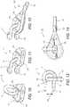
- Figures 1 through 5illustrate a first preferred embodiment 10 of the present invention showing the sequential installation of a thimble mechanism for retention of a shackle in a wire rope loop termination.
- the present inventionmay be used with a wide variety of standard shackles.
- the shackle 12has a body or bow 14 and a pair of extending legs 16 and 18. Each of the legs 16 and 18 terminates in an ear or end 20 and 22, respectively.
- Each end 20 and 22includes an opening to form a pair of opposed, aligned openings for receipt of a shackle bolt or screw pin.
- Each of the ends 20 and 22has in the direction of the aligned openings a width 70 which is smaller than the outer depth 71 of each of the ends 20 and 22 in a plane cross to the direction of the aligned openings.
- a thimble body 24includes an external arcuate edge with a thimble rope groove 26 recessed therein.
- the thimble rope groove 26forms the general contour of a loop for the wire rope.
- the thimble body 24includes a central opening 28, is larger than the width. At least one dimension of the contour of the central opening 28, especially the largest dimension, is larger than the width 70 but smaller than the depth 71 of the shackle ends 20 and 22.
- a slot or keyway 30is provided in the thimble body 24 with the keyway 30 extending from the central opening 28 to the thimble rope groove 26 of the thimble body 24.
- At least one dimension, especially the largest dimension, of the contour of the central opening 28 together with the contour of the keyway 30 limited by a rope which is lying in the rope groove 26,is larger than the width 70 but smaller than the depth 71 of the shackle ends 20 and 22.
- the bow 14 of the shackle 12is inserted or reeved through the keyway 30 and into the central opening 28 so that the bow 14 resides in the central opening 28 of the thimble body 24.
- the wire rope termination 10is thereafter completed in a variety of ways.
- a cylindrical sleeve 32is initially slipped or reeved onto a wire rope 34.
- the wire rope 34is reeved into place in and around the thimble rope groove 26.
- the cylindrical sleeve 32is swaged around the wire rope 34 to complete the loop termination.
- the wire rope 34closes the keyway 30 or slot and prevents the shackle 14 from being removed.
- the angle and the width of the central opening 28 and keywayprevent the end of the shackle 12 from being removed from the thimble body 24.
- Figures 6 through 9illustrate a second preferred embodiment 40 of the thimble mechanism for retention of a shackle in a wire rope loop termination employing a thimble with a retainer cross pin.
- a shackle 12has a body or bow 14 and a pair of extending legs 16 and 18. Each of the legs 16 and 18 terminates in an ear or end 20 and 22, respectively. Each end 20 and 22 includes an opening to form a pair of opposed, aligned openings for receipt of a shackle bolt (not shown). Each of the ends 20 and 22 has a width which is smaller than the depth.
- a thimble body 42includes an external arcuate edge with a thimble rope groove 44 which circumnavigates the thimble body 42.
- the thimble body 42may be seen apart from the assembly 40 in Figure 6 .
- the thimble rope groove 44forms the general contour of a loop for the receipt of the wire rope.
- the thimble body 42also includes a central opening 46 therethrough.
- the central openingis in the form of an oval which is larger than the width and the depth of the shackle ends 20 and 22, which can be best seen in Figure 6 .
- FIG. 6An installation sequence not being part of the invention is illustrated in Figures 6 through 9 .
- one end of the shacklesuch as end 20 is inserted or slipped through the central opening or slot 46 in the thimble body 42.
- the bow 14 of the shacklewill reside in the central opening, as best seen in Figure 7 .
- a retaining pin 48is inserted through a first opening 50 in the thimble body 42 into and across the central opening 46 and into an opposed, second opening 52 in the thimble body 42.
- the retaining pin 48 and the openings 50 and 52may be designed so that the retaining pin 48 will friction fit within the openings.
- the location of the openings and the pin 48are designed to retain the proper orientation of the shackle 12.
- a cylindrical sleeve 32will be slipped over or reeved onto an end of a wire rope 34. Thereafter, the wire rope 34 will be reeved or threaded in the thimble rope groove 44 of the thimble body 42 to form a termination loop. Finally, the sleeve 32 will be swaged or otherwise connected to the wire rope 34.
- the shackle ends 20 and 22will be prevented from being removed from the central opening of the thimble body 42 because the pin 48 reduces the size of the central opening. Additionally, the wire rope 34 discourages any movement or removal of the retaining pin 48 in the thimble body.
- Figures 10, 11, 12, 13 and 14illustrate another embodiment 60 not being part of the present invention showing sequential installation of a thimble mechanism for retention of a shackle in wire rope loop termination.
- the shackle 12has a body or bow 14 and a pair of extending legs 16 and 18. Each of the legs 16 and 18 terminates in an ear or end 20 and 22, respectively.
- Each end 20 and 22includes an opening to form a pair of opposed, aligned openings for receipt of a shackle bolt (not shown). There is a defined space between the ends 20 and 22 as seen in Figure 13 , and as shown by arrow 68.
- a thimble body 62includes an external arcuate edge with a thimble rope groove 64 recessed therein as best seen in Figures 10 and 11 .
- the thimble body 62also includes a central opening 66 for receipt of the shackle 12.
- one end of the shackle 12is inserted or reeved through the central opening 66 of the thimble body 62.
- the shackle 12may be slipped or inserted into the thimble body 62 without the wire rope installed.
- the bow 14 of the shackle 12will be suspended from the thimble body 62.
- a cylindrical sleeve 32will be slipped over or reeved onto an end of a wire rope 34.
- the wire rope 34will be reeved or threaded in the thimble rope groove 64 of the thimble body 62 in order to form a termination loop.
- the sleevewill be swedged or otherwise connected to the wire rope 34.
- the thimble body 62 and wire rope 34have a dimension which is larger than the defined space of the opening between the ends 20 and 22 of the legs 16 and 18 of the shackle. Accordingly, the shackle 12 cannot be removed.
Landscapes
- Engineering & Computer Science (AREA)
- General Engineering & Computer Science (AREA)
- Mechanical Engineering (AREA)
- Lift-Guide Devices, And Elevator Ropes And Cables (AREA)
Description
- The present invention relates to a thimble mechanism for retention of a shackle in a wire rope loop termination.
- There are a wide variety of terminations for metal wire rope which serve to discourage fraying of the end of the wire rope and serve to permit connection to a load.
- One such wire rope loop termination is accomplished in a number of manners. In one configuration, a clamp or clip is used to fix the loose end of the wire rope back to itself to form an oval or a loop. An example of a wire rope clip may be seen in Assignee's
U.S. Patent No. 5,802,680 titled "Two-Piece Bolt and Saddle for Wire Rope Clips". - In another configuration, a swage termination is formed by mechanically compressing and deforming a fitting. An example of a swage termination may be seen in Assignee's
U.S. Patent No. 6,035,692 titled "Two Pass Method and Apparatus of Forming a Hexagonal Swage for Wire Rope Terminations." Finally, an eye splice may be utilized as an alternate termination. - When there is a concern that a wire rope loop may bend too tightly under a load, a thimble may be utilized inside of the wire rope loop to preserve the shape of the loop, and to protect the wire rope from pinching and abrading on the inside of the loop. The thimble also prevents the load from coming into direct contact with the individual wires of the wire rope in order to spread the force of the load.
- Various types of shackles are often used to connect a load to a wire rope loop termination. Standard shackles include a body or bow and a pair of extending legs. Each leg terminates in an ear or end to form a pair of opposed, aligned openings for receipt of a shackle bolt. When in use, the body or bow of the shackle are engaged with the wire rope loop termination.
- Accordingly, it would be desirable to provide a thimble mechanism to encourage retention of the shackle in the wire rope loop termination after installation.
- It would also be desirable to provide a thimble mechanism with a thimble which retains a shackle in the thimble after a wire rope is installed around the thimble.
- It would also be desirable to provide a thimble mechanism for retention of a shackle in a wire rope loop termination that may be employed with any standard shackle design.
- It would also be desirable to provide a thimble mechanism for retention of a shackle in a wire rope loop termination utilizing a retainer pin that locks the shackle in place and that itself is locked by the wire rope loop in the thimble.
- It would also be desirable to provide a thimble mechanism which retains a shackle in a wire rope loop termination so that the shackle cannot be removed from the thimble mechanism after the wire rope is moved into place.
- Furthermore, from
US 2012/003 033 A1 a thimble device for a wire rope loop termination for retention of a shackle is known, the thimble device having a bow and a pair of opposed legs which thimble device comprises: - a thimble body having an external arched edge with a rope groove for receipt of a wire rope therein;
- a central opening through said thimble body,
- after receiving a wire rope around said rope groove, the remaining central opening having a size so that the shackle cannot be removed from said thimble body.
- The present invention is directed to a thimble mechanism for retention of a shackle in a wire rope loop termination.
- In one preferred embodiment, a thimble body includes an external arcuate edge with a thimble rope groove recessed therein. The thimble body includes a central opening larger than the width but smaller than the depth of shackle ends. A key way or slot is provided in the thimble body with the key way extending from the central opening to the thimble rope groove partially circumventing the thimble body.
- In order to install the thimble mechanism, the bow of the shackle is inserted or reeved through the key way and into the central opening so that the bow resides in the central opening of the thimble body. The wire rope termination is thereafter completed with the wire rope reeved into place in and around the thimble rope groove. Once the wire rope loop termination has been completed, the wire rope closes the key way or slot and prevents the shackle from being removed. The angle and the width of the central opening and the key way prevent the end of the shackle from being removed from the thimble body after the wire rope is installed.
- A second preferred embodiment employs a thimble body with an oval central opening and a retaining pin across the central opening.
- A third preferred embodiment employs a thimble body having a thimble rope groove dimensioned so that the shackle cannot be removed from the thimble mechanism after the wire rope is reeved into place in and around the thimble rope groove.
Figures1 through5 illustrate a first, preferred embodiment of the present invention showing sequential illustration of a thimble mechanism for retention of a shackle in a wire rope loop termination;Figures6 through9 illustrate an embodiment of a thimble mechanism for retention of a shackle in a wire rope loop termination employing a thimble with a retainer cross pin not being part of the invention andFigures10 through14 illustrate another embodiment of a thimble mechanism for retention of a shackle in a wire loop termination not being part of the invention.- The embodiments discussed herein are merely illustrative of specific manners in which to make and use the invention and are not to be interpreted as limiting the scope of the instant invention.
- While the invention has been described with a certain degree of particularity, it is to be noted that many modifications may be made in the details of the invention's construction and the arrangement of its components without departing from the spirit and scope of this disclosure. It is understood that the invention is not limited to the embodiments set forth herein for purposes of exemplification.
- Referring to the drawings in detail,
Figures1 through5 illustrate a firstpreferred embodiment 10 of the present invention showing the sequential installation of a thimble mechanism for retention of a shackle in a wire rope loop termination. - The present invention may be used with a wide variety of standard shackles. As seen in
Figure1 , theshackle 12 has a body orbow 14 and a pair of extendinglegs legs end end ends width 70 which is smaller than theouter depth 71 of each of theends - A
thimble body 24 includes an external arcuate edge with athimble rope groove 26 recessed therein. Thethimble rope groove 26 forms the general contour of a loop for the wire rope. Thethimble body 24 includes acentral opening 28, is larger than the width. At least one dimension of the contour of thecentral opening 28, especially the largest dimension, is larger than thewidth 70 but smaller than thedepth 71 of theshackle ends keyway 30 is provided in thethimble body 24 with thekeyway 30 extending from the central opening28 to thethimble rope groove 26 of thethimble body 24. At least one dimension, especially the largest dimension, of the contour of thecentral opening 28 together with the contour of thekeyway 30 limited by a rope which is lying in therope groove 26, is larger than thewidth 70 but smaller than thedepth 71 of theshackle ends - As seen in
Figure1 , in order to install the thimble mechanism, thebow 14 of theshackle 12 is inserted or reeved through thekeyway 30 and into thecentral opening 28 so that thebow 14 resides in thecentral opening 28 of thethimble body 24. - As seen in
Figure2 , thewire rope termination 10 is thereafter completed in a variety of ways. In the embodiment shown inFigure2 , acylindrical sleeve 32 is initially slipped or reeved onto awire rope 34. Thereafter, thewire rope 34 is reeved into place in and around thethimble rope groove 26. Finally, thecylindrical sleeve 32 is swaged around thewire rope 34 to complete the loop termination. Once the loop termination has been completed, thewire rope 34 closes thekeyway 30 or slot and prevents theshackle 14 from being removed. As seen inFigures3, 4 and5 , the angle and the width of thecentral opening 28 and keyway prevent the end of theshackle 12 from being removed from thethimble body 24. Figures6 through9 illustrate a secondpreferred embodiment 40 of the thimble mechanism for retention of a shackle in a wire rope loop termination employing a thimble with a retainer cross pin.- As in the previous embodiment, a
shackle 12 has a body or bow14 and a pair of extendinglegs legs end ends - A
thimble body 42 includes an external arcuate edge with athimble rope groove 44 which circumnavigates thethimble body 42. Thethimble body 42 may be seen apart from theassembly 40 inFigure6 . Thethimble rope groove 44 forms the general contour of a loop for the receipt of the wire rope. - The
thimble body 42 also includes acentral opening 46 therethrough. The central opening is in the form of an oval which is larger than the width and the depth of the shackle ends20 and22, which can be best seen inFigure6 . - An installation sequence not being part of the invention is illustrated in
Figures6 through9 . In order to install the thimble mechanism, as best seen inFigure6 , one end of the shackle, such asend 20, is inserted or slipped through the central opening orslot 46 in thethimble body 42. Once theend 20 has been inserted into and through the central opening, thebow 14 of the shackle will reside in the central opening, as best seen inFigure7 . - Thereafter, as seen in
Figure7 , a retainingpin 48 is inserted through afirst opening 50 in thethimble body 42 into and across thecentral opening 46 and into an opposed,second opening 52 in thethimble body 42. The retainingpin 48 and theopenings pin 48 will friction fit within the openings. In addition, the location of the openings and thepin 48 are designed to retain the proper orientation of theshackle 12. - Thereafter, as seen in
Figure8 , acylindrical sleeve 32 will be slipped over or reeved onto an end of awire rope 34. Thereafter, thewire rope 34 will be reeved or threaded in thethimble rope groove 44 of thethimble body 42 to form a termination loop. Finally, thesleeve 32 will be swaged or otherwise connected to thewire rope 34. - Thereafter, as best seen in
Figure9 , the shackle ends20 and22 will be prevented from being removed from the central opening of thethimble body 42 because thepin 48 reduces the size of the central opening. Additionally, thewire rope 34 discourages any movement or removal of the retainingpin 48 in the thimble body. Figures10, 11, 12, 13 and14 illustrate anotherembodiment 60 not being part of the present invention showing sequential installation of a thimble mechanism for retention of a shackle in wire rope loop termination. As in the previous embodiments, theshackle 12 has a body or bow14 and a pair of extendinglegs legs end ends Figure13 , and as shown byarrow 68.- A
thimble body 62 includes an external arcuate edge with athimble rope groove 64 recessed therein as best seen inFigures10 and11 . Thethimble body 62 also includes acentral opening 66 for receipt of theshackle 12. - As seen in
Figures10 and11 , in order to install thethimble mechanism 60, one end of theshackle 12 is inserted or reeved through thecentral opening 66 of thethimble body 62. Theshackle 12 may be slipped or inserted into thethimble body 62 without the wire rope installed. - Thereafter, as best seen in
Figure11 , thebow 14 of theshackle 12 will be suspended from thethimble body 62. Thereafter, as best seen inFigure12 , acylindrical sleeve 32 will be slipped over or reeved onto an end of awire rope 34. Thereafter, thewire rope 34 will be reeved or threaded in thethimble rope groove 64 of thethimble body 62 in order to form a termination loop. Finally, the sleeve will be swedged or otherwise connected to thewire rope 34. - As best seen in
Figures13 and14 , once the wire rope has been installed in therope groove 64, thethimble body 62 andwire rope 34 have a dimension which is larger than the defined space of the opening between theends legs shackle 12 cannot be removed. - 10
- wire rope loop termination
- 12
- shackle
- 14
- bow, body
- 16,18
- leg
- 20,22
- end
- 24
- thimble body
- 26
- thimble rope groove
- 28
- opening
- 30
- keyway
- 32
- sleeve
- 34
- wire rope
- 40
- embodiment
- 42
- thimble body
- 44
- groove
- 46
- opening
- 48
- pin
- 50,52
- opening
- 60
- thimble mechanism
- 62
- thimble body
- 64
- rope groove
- 66
- opening
- 68
- arrow
- 70
- width
- 71
- depth
Claims (2)
- A thimble device with- a thimble body (24) for a wire rope loop termination (10) and with- a shackle (12) having a bow (14) and a pair of opposed legs (16, 18) with each of said legs having an end (20, 22) with a width (70) smaller than a depth (71), which thimble device comprises:- a thimble body (24) having an external arcuate edge with a rope groove (26) for receipt of a wire rope therein;- a central opening (28) through said thimble body (24), said central opening (28) larger than said width (70) but smaller than said depth (71) of said shackle ends;- a keyway (30) in said thimble body (24) extending from said central opening (28) to said arcuate edge of said thimble body (24); andcharacterised in that- in use after receiving a wire rope (34) around said rope groove (26), the remaining central opening (28) has a size so that the shackle (12) cannot be removed from said thimble body (24) and wherein the wire rope (34) blocks the passage of the keyway (30) and prevents the shackle (12) from being removed.
- A method of retention of a shackle (12) in a wire rope loop termination (10) containing a thimble body (24) wherein said shackle (12) includes a bow (14) and a pair of opposed legs (16, 18) with each of said legs (16, 18) having an end (20, 22) with a width (70) smaller than a depth (71), which method comprises:- inserting the shackle (12) with its bow (14) extending through a central opening (28) of the thimble body (24) by passing through a keyway (30) in said thimble body (24) extending from said central opening (28) to an external arcuate edge of said thimble body (24);- reeving a wire rope (34) around a rope groove (26) in an external arcuate edge of said thimble body (24); and-characterised in that completing said wire rope loop termination (10) by forming a wire rope loop termination (10) in order to block the passage of said keyway (30) with said wire rope (34) and preventing the shackle (12) from being removed.
Applications Claiming Priority (1)
| Application Number | Priority Date | Filing Date | Title |
|---|---|---|---|
| US13/758,661US9003632B2 (en) | 2012-03-06 | 2013-02-04 | Thimble mechanism for retention of a shackle in a wire loop termination |
Publications (2)
| Publication Number | Publication Date |
|---|---|
| EP2787245A1 EP2787245A1 (en) | 2014-10-08 |
| EP2787245B1true EP2787245B1 (en) | 2017-10-11 |
Family
ID=50071427
Family Applications (1)
| Application Number | Title | Priority Date | Filing Date |
|---|---|---|---|
| EP14153676.3ANot-in-forceEP2787245B1 (en) | 2013-02-04 | 2014-02-03 | Thimble mechanism for retention of a shackle in a wire loop termination |
Country Status (1)
| Country | Link |
|---|---|
| EP (1) | EP2787245B1 (en) |
Family Cites Families (6)
| Publication number | Priority date | Publication date | Assignee | Title |
|---|---|---|---|---|
| US2709616A (en)* | 1952-09-15 | 1955-05-31 | Larson Victor Sjunne | Thimble ring for shackles |
| DE2746026C2 (en)* | 1977-10-13 | 1984-02-23 | Bruno 2390 Flensburg Marquardt | Flexible connection for thousands |
| US5802680A (en) | 1997-08-15 | 1998-09-08 | The Crosby Group, Inc. | Two-piece bolt and saddle for wire rope clips |
| US6035692A (en) | 1999-01-19 | 2000-03-14 | The Crosby Group, Inc. | Two pass method and apparatus of forming a hexagonal swage for wire rope terminations |
| US7743597B2 (en)* | 2008-08-26 | 2010-06-29 | General Pneumatics Corp. | Marine safety device attachment with automatic release capability |
| US8256981B2 (en)* | 2009-09-01 | 2012-09-04 | Delta Rigging & Tools, Inc. | Thimble with element retaining feature |
- 2014
- 2014-02-03EPEP14153676.3Apatent/EP2787245B1/ennot_activeNot-in-force
Non-Patent Citations (1)
| Title |
|---|
| None* |
Also Published As
| Publication number | Publication date |
|---|---|
| EP2787245A1 (en) | 2014-10-08 |
Similar Documents
| Publication | Publication Date | Title |
|---|---|---|
| EP3356698B1 (en) | Shackle pin split nut assembly | |
| US8256982B2 (en) | Thimble with element retaining feature | |
| US5427469A (en) | Cable restraining device | |
| EP2109723B1 (en) | Wire termination device | |
| US20180179702A1 (en) | Multi-pass crimp collar for a looped cable | |
| EP3193039B1 (en) | Synthetic rope termination | |
| US20150152669A1 (en) | Twistable Security Cable | |
| CN100343466C (en) | Sealing device | |
| US9416847B2 (en) | Capture block assembly for retaining shackles | |
| US9003632B2 (en) | Thimble mechanism for retention of a shackle in a wire loop termination | |
| US9890831B1 (en) | Shackle safety pin | |
| US9206829B2 (en) | Retaining pin assembly for a lifting system | |
| EP2974977B1 (en) | In-line cable tie with flexible head | |
| US6898827B1 (en) | Wedge socket with actuator assembly | |
| EP2787245B1 (en) | Thimble mechanism for retention of a shackle in a wire loop termination | |
| US10801582B2 (en) | Method and apparatus for retaining shackles using thimble retaining element | |
| EP3696446B1 (en) | Wedge clamp and steel wire | |
| EP3409975B1 (en) | Crimping collar and twistable security cable | |
| KR102352432B1 (en) | Spring hook mounting device for healthcare with increased productivity | |
| US20210018064A1 (en) | Bidirectional Wedge Clamp | |
| RU16514U1 (en) | FILLING DEVICE | |
| CA2163310A1 (en) | Spring clip |
Legal Events
| Date | Code | Title | Description |
|---|---|---|---|
| PUAI | Public reference made under article 153(3) epc to a published international application that has entered the european phase | Free format text:ORIGINAL CODE: 0009012 | |
| 17P | Request for examination filed | Effective date:20140203 | |
| AK | Designated contracting states | Kind code of ref document:A1 Designated state(s):AL AT BE BG CH CY CZ DE DK EE ES FI FR GB GR HR HU IE IS IT LI LT LU LV MC MK MT NL NO PL PT RO RS SE SI SK SM TR | |
| AX | Request for extension of the european patent | Extension state:BA ME | |
| R17P | Request for examination filed (corrected) | Effective date:20150408 | |
| RBV | Designated contracting states (corrected) | Designated state(s):AL AT BE BG CH CY CZ DE DK EE ES FI FR GB GR HR HU IE IS IT LI LT LU LV MC MK MT NL NO PL PT RO RS SE SI SK SM TR | |
| 17Q | First examination report despatched | Effective date:20160404 | |
| GRAP | Despatch of communication of intention to grant a patent | Free format text:ORIGINAL CODE: EPIDOSNIGR1 | |
| INTG | Intention to grant announced | Effective date:20170424 | |
| GRAS | Grant fee paid | Free format text:ORIGINAL CODE: EPIDOSNIGR3 | |
| GRAA | (expected) grant | Free format text:ORIGINAL CODE: 0009210 | |
| AK | Designated contracting states | Kind code of ref document:B1 Designated state(s):AL AT BE BG CH CY CZ DE DK EE ES FI FR GB GR HR HU IE IS IT LI LT LU LV MC MK MT NL NO PL PT RO RS SE SI SK SM TR | |
| REG | Reference to a national code | Ref country code:GB Ref legal event code:FG4D | |
| REG | Reference to a national code | Ref country code:CH Ref legal event code:EP | |
| REG | Reference to a national code | Ref country code:IE Ref legal event code:FG4D | |
| REG | Reference to a national code | Ref country code:AT Ref legal event code:REF Ref document number:936347 Country of ref document:AT Kind code of ref document:T Effective date:20171115 | |
| REG | Reference to a national code | Ref country code:DE Ref legal event code:R096 Ref document number:602014015566 Country of ref document:DE | |
| REG | Reference to a national code | Ref country code:NL Ref legal event code:FP | |
| REG | Reference to a national code | Ref country code:LT Ref legal event code:MG4D Ref country code:NO Ref legal event code:T2 Effective date:20171011 | |
| REG | Reference to a national code | Ref country code:AT Ref legal event code:MK05 Ref document number:936347 Country of ref document:AT Kind code of ref document:T Effective date:20171011 | |
| PGFP | Annual fee paid to national office [announced via postgrant information from national office to epo] | Ref country code:NL Payment date:20180221 Year of fee payment:5 | |
| PG25 | Lapsed in a contracting state [announced via postgrant information from national office to epo] | Ref country code:FI Free format text:LAPSE BECAUSE OF FAILURE TO SUBMIT A TRANSLATION OF THE DESCRIPTION OR TO PAY THE FEE WITHIN THE PRESCRIBED TIME-LIMIT Effective date:20171011 Ref country code:LT Free format text:LAPSE BECAUSE OF FAILURE TO SUBMIT A TRANSLATION OF THE DESCRIPTION OR TO PAY THE FEE WITHIN THE PRESCRIBED TIME-LIMIT Effective date:20171011 Ref country code:SE Free format text:LAPSE BECAUSE OF FAILURE TO SUBMIT A TRANSLATION OF THE DESCRIPTION OR TO PAY THE FEE WITHIN THE PRESCRIBED TIME-LIMIT Effective date:20171011 Ref country code:ES Free format text:LAPSE BECAUSE OF FAILURE TO SUBMIT A TRANSLATION OF THE DESCRIPTION OR TO PAY THE FEE WITHIN THE PRESCRIBED TIME-LIMIT Effective date:20171011 | |
| PGFP | Annual fee paid to national office [announced via postgrant information from national office to epo] | Ref country code:DE Payment date:20180226 Year of fee payment:5 Ref country code:NO Payment date:20180221 Year of fee payment:5 Ref country code:GB Payment date:20180221 Year of fee payment:5 | |
| PG25 | Lapsed in a contracting state [announced via postgrant information from national office to epo] | Ref country code:IS Free format text:LAPSE BECAUSE OF FAILURE TO SUBMIT A TRANSLATION OF THE DESCRIPTION OR TO PAY THE FEE WITHIN THE PRESCRIBED TIME-LIMIT Effective date:20180211 Ref country code:BG Free format text:LAPSE BECAUSE OF FAILURE TO SUBMIT A TRANSLATION OF THE DESCRIPTION OR TO PAY THE FEE WITHIN THE PRESCRIBED TIME-LIMIT Effective date:20180111 Ref country code:RS Free format text:LAPSE BECAUSE OF FAILURE TO SUBMIT A TRANSLATION OF THE DESCRIPTION OR TO PAY THE FEE WITHIN THE PRESCRIBED TIME-LIMIT Effective date:20171011 Ref country code:AT Free format text:LAPSE BECAUSE OF FAILURE TO SUBMIT A TRANSLATION OF THE DESCRIPTION OR TO PAY THE FEE WITHIN THE PRESCRIBED TIME-LIMIT Effective date:20171011 Ref country code:HR Free format text:LAPSE BECAUSE OF FAILURE TO SUBMIT A TRANSLATION OF THE DESCRIPTION OR TO PAY THE FEE WITHIN THE PRESCRIBED TIME-LIMIT Effective date:20171011 Ref country code:GR Free format text:LAPSE BECAUSE OF FAILURE TO SUBMIT A TRANSLATION OF THE DESCRIPTION OR TO PAY THE FEE WITHIN THE PRESCRIBED TIME-LIMIT Effective date:20180112 Ref country code:LV Free format text:LAPSE BECAUSE OF FAILURE TO SUBMIT A TRANSLATION OF THE DESCRIPTION OR TO PAY THE FEE WITHIN THE PRESCRIBED TIME-LIMIT Effective date:20171011 | |
| PGFP | Annual fee paid to national office [announced via postgrant information from national office to epo] | Ref country code:BE Payment date:20180221 Year of fee payment:5 | |
| REG | Reference to a national code | Ref country code:DE Ref legal event code:R097 Ref document number:602014015566 Country of ref document:DE | |
| PG25 | Lapsed in a contracting state [announced via postgrant information from national office to epo] | Ref country code:SK Free format text:LAPSE BECAUSE OF FAILURE TO SUBMIT A TRANSLATION OF THE DESCRIPTION OR TO PAY THE FEE WITHIN THE PRESCRIBED TIME-LIMIT Effective date:20171011 Ref country code:DK Free format text:LAPSE BECAUSE OF FAILURE TO SUBMIT A TRANSLATION OF THE DESCRIPTION OR TO PAY THE FEE WITHIN THE PRESCRIBED TIME-LIMIT Effective date:20171011 Ref country code:EE Free format text:LAPSE BECAUSE OF FAILURE TO SUBMIT A TRANSLATION OF THE DESCRIPTION OR TO PAY THE FEE WITHIN THE PRESCRIBED TIME-LIMIT Effective date:20171011 Ref country code:CZ Free format text:LAPSE BECAUSE OF FAILURE TO SUBMIT A TRANSLATION OF THE DESCRIPTION OR TO PAY THE FEE WITHIN THE PRESCRIBED TIME-LIMIT Effective date:20171011 | |
| PLBE | No opposition filed within time limit | Free format text:ORIGINAL CODE: 0009261 | |
| STAA | Information on the status of an ep patent application or granted ep patent | Free format text:STATUS: NO OPPOSITION FILED WITHIN TIME LIMIT | |
| PG25 | Lapsed in a contracting state [announced via postgrant information from national office to epo] | Ref country code:IT Free format text:LAPSE BECAUSE OF FAILURE TO SUBMIT A TRANSLATION OF THE DESCRIPTION OR TO PAY THE FEE WITHIN THE PRESCRIBED TIME-LIMIT Effective date:20171011 Ref country code:PL Free format text:LAPSE BECAUSE OF FAILURE TO SUBMIT A TRANSLATION OF THE DESCRIPTION OR TO PAY THE FEE WITHIN THE PRESCRIBED TIME-LIMIT Effective date:20171011 Ref country code:SM Free format text:LAPSE BECAUSE OF FAILURE TO SUBMIT A TRANSLATION OF THE DESCRIPTION OR TO PAY THE FEE WITHIN THE PRESCRIBED TIME-LIMIT Effective date:20171011 Ref country code:RO Free format text:LAPSE BECAUSE OF FAILURE TO SUBMIT A TRANSLATION OF THE DESCRIPTION OR TO PAY THE FEE WITHIN THE PRESCRIBED TIME-LIMIT Effective date:20171011 | |
| REG | Reference to a national code | Ref country code:CH Ref legal event code:PL | |
| 26N | No opposition filed | Effective date:20180712 | |
| PG25 | Lapsed in a contracting state [announced via postgrant information from national office to epo] | Ref country code:MC Free format text:LAPSE BECAUSE OF FAILURE TO SUBMIT A TRANSLATION OF THE DESCRIPTION OR TO PAY THE FEE WITHIN THE PRESCRIBED TIME-LIMIT Effective date:20171011 | |
| REG | Reference to a national code | Ref country code:IE Ref legal event code:MM4A | |
| PG25 | Lapsed in a contracting state [announced via postgrant information from national office to epo] | Ref country code:LI Free format text:LAPSE BECAUSE OF NON-PAYMENT OF DUE FEES Effective date:20180228 Ref country code:CH Free format text:LAPSE BECAUSE OF NON-PAYMENT OF DUE FEES Effective date:20180228 Ref country code:SI Free format text:LAPSE BECAUSE OF FAILURE TO SUBMIT A TRANSLATION OF THE DESCRIPTION OR TO PAY THE FEE WITHIN THE PRESCRIBED TIME-LIMIT Effective date:20171011 Ref country code:LU Free format text:LAPSE BECAUSE OF NON-PAYMENT OF DUE FEES Effective date:20180203 | |
| REG | Reference to a national code | Ref country code:FR Ref legal event code:ST Effective date:20181031 | |
| PG25 | Lapsed in a contracting state [announced via postgrant information from national office to epo] | Ref country code:IE Free format text:LAPSE BECAUSE OF NON-PAYMENT OF DUE FEES Effective date:20180203 | |
| PG25 | Lapsed in a contracting state [announced via postgrant information from national office to epo] | Ref country code:FR Free format text:LAPSE BECAUSE OF NON-PAYMENT OF DUE FEES Effective date:20180228 | |
| REG | Reference to a national code | Ref country code:DE Ref legal event code:R119 Ref document number:602014015566 Country of ref document:DE | |
| REG | Reference to a national code | Ref country code:NO Ref legal event code:MMEP | |
| REG | Reference to a national code | Ref country code:NL Ref legal event code:MM Effective date:20190301 | |
| GBPC | Gb: european patent ceased through non-payment of renewal fee | Effective date:20190203 | |
| PG25 | Lapsed in a contracting state [announced via postgrant information from national office to epo] | Ref country code:NO Free format text:LAPSE BECAUSE OF NON-PAYMENT OF DUE FEES Effective date:20190228 | |
| REG | Reference to a national code | Ref country code:BE Ref legal event code:MM Effective date:20190228 | |
| PG25 | Lapsed in a contracting state [announced via postgrant information from national office to epo] | Ref country code:GB Free format text:LAPSE BECAUSE OF NON-PAYMENT OF DUE FEES Effective date:20190203 Ref country code:NL Free format text:LAPSE BECAUSE OF NON-PAYMENT OF DUE FEES Effective date:20190301 Ref country code:DE Free format text:LAPSE BECAUSE OF NON-PAYMENT OF DUE FEES Effective date:20190903 Ref country code:MT Free format text:LAPSE BECAUSE OF NON-PAYMENT OF DUE FEES Effective date:20180203 | |
| PG25 | Lapsed in a contracting state [announced via postgrant information from national office to epo] | Ref country code:BE Free format text:LAPSE BECAUSE OF NON-PAYMENT OF DUE FEES Effective date:20190228 | |
| PG25 | Lapsed in a contracting state [announced via postgrant information from national office to epo] | Ref country code:TR Free format text:LAPSE BECAUSE OF FAILURE TO SUBMIT A TRANSLATION OF THE DESCRIPTION OR TO PAY THE FEE WITHIN THE PRESCRIBED TIME-LIMIT Effective date:20171011 | |
| PG25 | Lapsed in a contracting state [announced via postgrant information from national office to epo] | Ref country code:PT Free format text:LAPSE BECAUSE OF FAILURE TO SUBMIT A TRANSLATION OF THE DESCRIPTION OR TO PAY THE FEE WITHIN THE PRESCRIBED TIME-LIMIT Effective date:20171011 Ref country code:HU Free format text:LAPSE BECAUSE OF FAILURE TO SUBMIT A TRANSLATION OF THE DESCRIPTION OR TO PAY THE FEE WITHIN THE PRESCRIBED TIME-LIMIT; INVALID AB INITIO Effective date:20140203 | |
| PG25 | Lapsed in a contracting state [announced via postgrant information from national office to epo] | Ref country code:CY Free format text:LAPSE BECAUSE OF FAILURE TO SUBMIT A TRANSLATION OF THE DESCRIPTION OR TO PAY THE FEE WITHIN THE PRESCRIBED TIME-LIMIT Effective date:20171011 Ref country code:MK Free format text:LAPSE BECAUSE OF NON-PAYMENT OF DUE FEES Effective date:20171011 | |
| PG25 | Lapsed in a contracting state [announced via postgrant information from national office to epo] | Ref country code:AL Free format text:LAPSE BECAUSE OF FAILURE TO SUBMIT A TRANSLATION OF THE DESCRIPTION OR TO PAY THE FEE WITHIN THE PRESCRIBED TIME-LIMIT Effective date:20171011 |