EP2786802A1 - Lock for a container - Google Patents
Lock for a containerDownload PDFInfo
- Publication number
- EP2786802A1 EP2786802A1EP13162169.0AEP13162169AEP2786802A1EP 2786802 A1EP2786802 A1EP 2786802A1EP 13162169 AEP13162169 AEP 13162169AEP 2786802 A1EP2786802 A1EP 2786802A1
- Authority
- EP
- European Patent Office
- Prior art keywords
- closure
- adapter
- container
- sealing device
- coupling
- Prior art date
- Legal status (The legal status is an assumption and is not a legal conclusion. Google has not performed a legal analysis and makes no representation as to the accuracy of the status listed.)
- Withdrawn
Links
- 238000007789sealingMethods0.000claimsabstractdescription82
- 230000008878couplingEffects0.000claimsabstractdescription76
- 238000010168coupling processMethods0.000claimsabstractdescription76
- 238000005859coupling reactionMethods0.000claimsabstractdescription76
- 239000012530fluidSubstances0.000claimsdescription41
- 238000003780insertionMethods0.000claimsdescription11
- 230000037431insertionEffects0.000claimsdescription11
- 230000005540biological transmissionEffects0.000claimsdescription3
- 238000011156evaluationMethods0.000claimsdescription3
- 239000007788liquidSubstances0.000claims2
- 239000003570airSubstances0.000description31
- 238000000034methodMethods0.000description11
- 206010053648Vascular occlusionDiseases0.000description9
- KWYUFKZDYYNOTN-UHFFFAOYSA-MPotassium hydroxideChemical compound[OH-].[K+]KWYUFKZDYYNOTN-UHFFFAOYSA-M0.000description6
- HEMHJVSKTPXQMS-UHFFFAOYSA-MSodium hydroxideChemical compound[OH-].[Na+]HEMHJVSKTPXQMS-UHFFFAOYSA-M0.000description6
- 238000011109contaminationMethods0.000description4
- 230000035515penetrationEffects0.000description4
- 239000000463materialSubstances0.000description3
- 230000015572biosynthetic processEffects0.000description2
- 238000004519manufacturing processMethods0.000description2
- 230000013011matingEffects0.000description2
- 239000000203mixtureSubstances0.000description2
- 229920000139polyethylene terephthalatePolymers0.000description2
- 239000005020polyethylene terephthalateSubstances0.000description2
- HUAUNKAZQWMVFY-UHFFFAOYSA-Msodium;oxocalcium;hydroxideChemical compound[OH-].[Na+].[Ca]=OHUAUNKAZQWMVFY-UHFFFAOYSA-M0.000description2
- BZSHLPGOHIOWDF-UHFFFAOYSA-NC1C2=CCC1C2Chemical compoundC1C2=CCC1C2BZSHLPGOHIOWDF-UHFFFAOYSA-N0.000description1
- 241001417534LutjanidaeSpecies0.000description1
- VYPSYNLAJGMNEJ-UHFFFAOYSA-NSilicium dioxideChemical compoundO=[Si]=OVYPSYNLAJGMNEJ-UHFFFAOYSA-N0.000description1
- 239000006096absorbing agentSubstances0.000description1
- 239000012080ambient airSubstances0.000description1
- RQPZNWPYLFFXCP-UHFFFAOYSA-Lbarium dihydroxideChemical compound[OH-].[OH-].[Ba+2]RQPZNWPYLFFXCP-UHFFFAOYSA-L0.000description1
- 229910001863barium hydroxideInorganic materials0.000description1
- 239000011575calciumSubstances0.000description1
- AXCZMVOFGPJBDE-UHFFFAOYSA-Lcalcium dihydroxideChemical compound[OH-].[OH-].[Ca+2]AXCZMVOFGPJBDE-UHFFFAOYSA-L0.000description1
- 239000000920calcium hydroxideSubstances0.000description1
- 229910001861calcium hydroxideInorganic materials0.000description1
- 238000005520cutting processMethods0.000description1
- 238000001514detection methodMethods0.000description1
- 239000006185dispersionSubstances0.000description1
- 238000006073displacement reactionMethods0.000description1
- 238000009826distributionMethods0.000description1
- 238000000605extractionMethods0.000description1
- 239000002808molecular sieveSubstances0.000description1
- -1polyethylene terephthalatePolymers0.000description1
- 239000004810polytetrafluoroethyleneSubstances0.000description1
- 229920001343polytetrafluoroethylenePolymers0.000description1
- 230000002028prematureEffects0.000description1
- 238000003825pressingMethods0.000description1
- 230000001681protective effectEffects0.000description1
- 239000000741silica gelSubstances0.000description1
- 229910002027silica gelInorganic materials0.000description1
- URGAHOPLAPQHLN-UHFFFAOYSA-Nsodium aluminosilicateChemical compound[Na+].[Al+3].[O-][Si]([O-])=O.[O-][Si]([O-])=OURGAHOPLAPQHLN-UHFFFAOYSA-N0.000description1
- 238000003860storageMethods0.000description1
- 210000002435tendonAnatomy0.000description1
- 230000000007visual effectEffects0.000description1
Images


Classifications
- B—PERFORMING OPERATIONS; TRANSPORTING
- B01—PHYSICAL OR CHEMICAL PROCESSES OR APPARATUS IN GENERAL
- B01L—CHEMICAL OR PHYSICAL LABORATORY APPARATUS FOR GENERAL USE
- B01L3/00—Containers or dishes for laboratory use, e.g. laboratory glassware; Droppers
- B—PERFORMING OPERATIONS; TRANSPORTING
- B65—CONVEYING; PACKING; STORING; HANDLING THIN OR FILAMENTARY MATERIAL
- B65D—CONTAINERS FOR STORAGE OR TRANSPORT OF ARTICLES OR MATERIALS, e.g. BAGS, BARRELS, BOTTLES, BOXES, CANS, CARTONS, CRATES, DRUMS, JARS, TANKS, HOPPERS, FORWARDING CONTAINERS; ACCESSORIES, CLOSURES, OR FITTINGS THEREFOR; PACKAGING ELEMENTS; PACKAGES
- B65D51/00—Closures not otherwise provided for
- B65D51/16—Closures not otherwise provided for with means for venting air or gas
- B65D51/1672—Closures not otherwise provided for with means for venting air or gas whereby venting occurs by manual actuation of the closure or other element
- B65D51/1683—Closures not otherwise provided for with means for venting air or gas whereby venting occurs by manual actuation of the closure or other element by actuating a separate element in the container or closure
- B—PERFORMING OPERATIONS; TRANSPORTING
- B01—PHYSICAL OR CHEMICAL PROCESSES OR APPARATUS IN GENERAL
- B01L—CHEMICAL OR PHYSICAL LABORATORY APPARATUS FOR GENERAL USE
- B01L3/00—Containers or dishes for laboratory use, e.g. laboratory glassware; Droppers
- B01L3/50—Containers for the purpose of retaining a material to be analysed, e.g. test tubes
- B01L3/508—Containers for the purpose of retaining a material to be analysed, e.g. test tubes rigid containers not provided for above
- B01L3/5082—Test tubes per se
- B01L3/50825—Closing or opening means, corks, bungs
- A—HUMAN NECESSITIES
- A61—MEDICAL OR VETERINARY SCIENCE; HYGIENE
- A61J—CONTAINERS SPECIALLY ADAPTED FOR MEDICAL OR PHARMACEUTICAL PURPOSES; DEVICES OR METHODS SPECIALLY ADAPTED FOR BRINGING PHARMACEUTICAL PRODUCTS INTO PARTICULAR PHYSICAL OR ADMINISTERING FORMS; DEVICES FOR ADMINISTERING FOOD OR MEDICINES ORALLY; BABY COMFORTERS; DEVICES FOR RECEIVING SPITTLE
- A61J1/00—Containers specially adapted for medical or pharmaceutical purposes
- A61J1/14—Details; Accessories therefor
- A61J1/20—Arrangements for transferring or mixing fluids, e.g. from vial to syringe
- A—HUMAN NECESSITIES
- A61—MEDICAL OR VETERINARY SCIENCE; HYGIENE
- A61M—DEVICES FOR INTRODUCING MEDIA INTO, OR ONTO, THE BODY; DEVICES FOR TRANSDUCING BODY MEDIA OR FOR TAKING MEDIA FROM THE BODY; DEVICES FOR PRODUCING OR ENDING SLEEP OR STUPOR
- A61M39/00—Tubes, tube connectors, tube couplings, valves, access sites or the like, specially adapted for medical use
- A61M39/10—Tube connectors; Tube couplings
- B—PERFORMING OPERATIONS; TRANSPORTING
- B01—PHYSICAL OR CHEMICAL PROCESSES OR APPARATUS IN GENERAL
- B01L—CHEMICAL OR PHYSICAL LABORATORY APPARATUS FOR GENERAL USE
- B01L3/00—Containers or dishes for laboratory use, e.g. laboratory glassware; Droppers
- B01L3/56—Labware specially adapted for transferring fluids
- B01L3/563—Joints or fittings ; Separable fluid transfer means to transfer fluids between at least two containers, e.g. connectors
- B—PERFORMING OPERATIONS; TRANSPORTING
- B65—CONVEYING; PACKING; STORING; HANDLING THIN OR FILAMENTARY MATERIAL
- B65D—CONTAINERS FOR STORAGE OR TRANSPORT OF ARTICLES OR MATERIALS, e.g. BAGS, BARRELS, BOTTLES, BOXES, CANS, CARTONS, CRATES, DRUMS, JARS, TANKS, HOPPERS, FORWARDING CONTAINERS; ACCESSORIES, CLOSURES, OR FITTINGS THEREFOR; PACKAGING ELEMENTS; PACKAGES
- B65D51/00—Closures not otherwise provided for
- B65D51/24—Closures not otherwise provided for combined or co-operating with auxiliary devices for non-closing purposes
- B65D51/245—Closures not otherwise provided for combined or co-operating with auxiliary devices for non-closing purposes provided with decoration, information or contents indicating devices, labels
- B—PERFORMING OPERATIONS; TRANSPORTING
- B65—CONVEYING; PACKING; STORING; HANDLING THIN OR FILAMENTARY MATERIAL
- B65D—CONTAINERS FOR STORAGE OR TRANSPORT OF ARTICLES OR MATERIALS, e.g. BAGS, BARRELS, BOTTLES, BOXES, CANS, CARTONS, CRATES, DRUMS, JARS, TANKS, HOPPERS, FORWARDING CONTAINERS; ACCESSORIES, CLOSURES, OR FITTINGS THEREFOR; PACKAGING ELEMENTS; PACKAGES
- B65D51/00—Closures not otherwise provided for
- B65D51/24—Closures not otherwise provided for combined or co-operating with auxiliary devices for non-closing purposes
- B65D51/26—Closures not otherwise provided for combined or co-operating with auxiliary devices for non-closing purposes with means for keeping contents in position, e.g. resilient means
- B—PERFORMING OPERATIONS; TRANSPORTING
- B01—PHYSICAL OR CHEMICAL PROCESSES OR APPARATUS IN GENERAL
- B01L—CHEMICAL OR PHYSICAL LABORATORY APPARATUS FOR GENERAL USE
- B01L2200/00—Solutions for specific problems relating to chemical or physical laboratory apparatus
- B01L2200/02—Adapting objects or devices to another
- B01L2200/025—Align devices or objects to ensure defined positions relative to each other
- B—PERFORMING OPERATIONS; TRANSPORTING
- B01—PHYSICAL OR CHEMICAL PROCESSES OR APPARATUS IN GENERAL
- B01L—CHEMICAL OR PHYSICAL LABORATORY APPARATUS FOR GENERAL USE
- B01L2200/00—Solutions for specific problems relating to chemical or physical laboratory apparatus
- B01L2200/02—Adapting objects or devices to another
- B01L2200/026—Fluid interfacing between devices or objects, e.g. connectors, inlet details
- B—PERFORMING OPERATIONS; TRANSPORTING
- B01—PHYSICAL OR CHEMICAL PROCESSES OR APPARATUS IN GENERAL
- B01L—CHEMICAL OR PHYSICAL LABORATORY APPARATUS FOR GENERAL USE
- B01L2200/00—Solutions for specific problems relating to chemical or physical laboratory apparatus
- B01L2200/06—Fluid handling related problems
- B01L2200/0689—Sealing
- B—PERFORMING OPERATIONS; TRANSPORTING
- B01—PHYSICAL OR CHEMICAL PROCESSES OR APPARATUS IN GENERAL
- B01L—CHEMICAL OR PHYSICAL LABORATORY APPARATUS FOR GENERAL USE
- B01L2200/00—Solutions for specific problems relating to chemical or physical laboratory apparatus
- B01L2200/14—Process control and prevention of errors
- B01L2200/141—Preventing contamination, tampering
- B—PERFORMING OPERATIONS; TRANSPORTING
- B01—PHYSICAL OR CHEMICAL PROCESSES OR APPARATUS IN GENERAL
- B01L—CHEMICAL OR PHYSICAL LABORATORY APPARATUS FOR GENERAL USE
- B01L2300/00—Additional constructional details
- B01L2300/02—Identification, exchange or storage of information
- B01L2300/021—Identification, e.g. bar codes
- B01L2300/022—Transponder chips
- B—PERFORMING OPERATIONS; TRANSPORTING
- B01—PHYSICAL OR CHEMICAL PROCESSES OR APPARATUS IN GENERAL
- B01L—CHEMICAL OR PHYSICAL LABORATORY APPARATUS FOR GENERAL USE
- B01L2300/00—Additional constructional details
- B01L2300/04—Closures and closing means
- B01L2300/046—Function or devices integrated in the closure
- B01L2300/048—Function or devices integrated in the closure enabling gas exchange, e.g. vents
- B—PERFORMING OPERATIONS; TRANSPORTING
- B01—PHYSICAL OR CHEMICAL PROCESSES OR APPARATUS IN GENERAL
- B01L—CHEMICAL OR PHYSICAL LABORATORY APPARATUS FOR GENERAL USE
- B01L2300/00—Additional constructional details
- B01L2300/06—Auxiliary integrated devices, integrated components
- B01L2300/0681—Filter
Definitions
- the inventionrelates to a closure for a container, an adapter for a closure, an adapter system, a method for removing a fluid from a container, a display element for displaying a functional state, a sealing device and the use of an adapter and / or a closure according to the preambles the independent claims.
- process reliability and process quality when using a wide variety of fluidsare essential. Furthermore, it is advantageous if the ease of use is increased for the user, which also contributes to process safety.
- a closure for a containerwhich comprises a connecting element for connecting the closure with a container and a sealing device for sealing the access to a container contents. Furthermore, the closure comprises an interface to an adapter with a coupling receptacle, wherein the closure has a delivery position and a use position. In the delivery position, the sealing device is closed gas-tight and liquid-tight, wherein the sealing device is open in a use position.
- a container provided with such a closureis closed to the outside substantially gas and liquid-tight, as will be explained in detail below.
- Such a closureallows contamination-free and leak-free transport of a fluid in a container and easy connection to an adapter, wherein the closure is opened during or before connection to an adapter.
- the delivery position of the closureincludes a sealed seal, and preferably a closure of air supply and exhaust ducts.
- the sealIn the use position, the seal is opened and fluid from a container can be removed through the closure.
- the fluidpreferably does not come into direct contact with outside air, as will be explained below.
- the connecting elementmay comprise a thread.
- a threadallows attaching the closure easily and easily to a matching mating thread of a container. Furthermore, of course, bayonet locks or snaps are possible.
- the closuremay comprise a lid member for opening and closing the closure, the lid member preferably being securable by a break element indicating initial opening.
- Such a lid memberallows a closure and reopening of the closure after opening the sealing device in a use position.
- Another break element on the lid member for indicating initial openingmakes the closure tamper-proof.
- the closuremay comprise a filter element, through which, especially in the use position, outside air can be conducted from the outside through the closure into a container.
- an air supplyis advantageous in order to allow a pressure equalization.
- the use of a filter elementprevents the contamination of the contents of the container by direct external air and thus allows an accurate and high quality work.
- Filter elementsare preferably equipped with a material which is suitable for removing portions of the ambient air, which may cause a change in the container contents.
- the respective materialis matched to the respective container contents in routine routine measures.
- suitable materialsare soda lime (also known as soda lime mixture of calcium hydroxide Ca (OH) 2 and sodium hydroxide NaOH, or a mixture of potassium hydroxide KOH and barium hydroxide Ba (OH) 2 ); particulate filter; Molecular sieves, silica gel.
- Channels for the supply and removal of airmay be designed to be closable in the closure, preferably closable by the sealing device, wherein the sealing device closes the channels particularly preferably in the delivery position with closed seal.
- defined channels for the supply and removal of airallow a particularly safe and contamination-free work.
- the airis preferably passed through a filter element before coming in contact with the contents of the container.
- the channelsare preferably closed in a delivery position and are only opened in a use position.
- the channels for the supply and discharge of air in the closuremay be particularly preferably equipped as female Lueran say (with an inner cone) or with a thread.
- a hose for the supply of protective gascan be attached to the closure in a particularly simple manner.
- the closuremay comprise a fixing element which fixes the closure in a delivery position, wherein the fixing element is detachably formed.
- the fixing elementis particularly preferably detachably designed detachable and after the solution and preferably removal of the fixing element, the closure can be brought into a position of use.
- Such a fixing elementprevents premature reaching the use position of the closure, if this is not yet wanted. Furthermore, such a fixing element a visual indication of the opening state and / or the delivery or use position of the closure. Thus, a flawless working is easily possible.
- the closuremay comprise a data carrier, preferably a data carrier with a destructible data transmission element, in particular preferably an RFID chip.
- a data carrierallows the automatic detection of the shutter and the data stored on the data carrier, such as data of the associated container and the contents of the container. This leads to a secure way of working, as important data can be transmitted. For example, the contents of the container can be recognized without errors. Furthermore, data such as volume, shelf life data or withdrawn amounts can be detected via the data carrier or stored on this. This leads to high quality results.
- the data carriercan be designed optically and / or electronically.
- the coupling receptaclecan be designed to be movable along a longitudinal axis of the closure from a delivery position into a use position.
- the use positioncan be achieved when engaging a suitable coupling element for the coupling receptacle.
- the opening of the sealing devicecan in particular be carried out independently of the use of the adapter, preferably by simply pressing down the closure, wherein a suitable adapter is then attached in a subsequent step.
- the closureis preferably gas-tight and liquid-tight in a delivery position. In a use position, fluid may be passed out of the container through the closure. Nevertheless, the gas supply or air supply is controlled by a filter element, so that no contamination of the contents of the container can occur.
- the sealing devicecan be opened, preferably broken, whereby the closure can be fixed in the use position after the sealing device has broken open.
- the coupling receptacleremains after the breaking of the seal in a use position and is recognizable to the user already needed. This increases safety and makes the use of the closure easy and reliable for the user.
- the airin particular cleaned by a filter element, can be conducted through the closure.
- the supply of airallows pressure equalization and thus facilitates the removal of fluid from the container under contamination-free conditions.
- the coupling receptaclemay comprise engagement grooves, preferably eight engagement grooves.
- the formation of engagement groovesallows a precise insertion of a coupling element and a dedicated orientation of an adapter on the closure. Furthermore, the power transmission from adapter to the closure is optimized.
- the closuremay comprise at least one fixing element to which an adapter can be fastened.
- Such a fixing elementmay comprise an undercut or edge or holding surface, which can be encompassed by engagement elements of an adapter.
- an adapteris securely fixed on the closure.
- To achieve the objectfurther leads to a container which is connected to a closure as described above, preferably closed to the outside substantially gas and liquid-tight.
- Such a containercan be easily and safely connected to an adapter and allows safe storage and contamination-free and easy removal of fluid from the container.
- an adapter for a closurepreferably a closure as described above, comprising a connection point to a device, preferably an evaluation unit and an interface to a closure.
- the interfacefurther comprises a coupling element, which is engageable with a coupling receptacle of a closure, so that a fluid flow through the adapter can be generated, without a direct contact of outside air and fluid.
- Such an adapterallows the contamination-free and easy removal of a fluid from a container and the continuation in a device which requires the fluid.
- the workload for a useris simplified and reduced, and process reliability increases.
- the coupling elementmay comprise engagement elements, preferably eight engagement elements, which are insertable into engagement grooves of a coupling receptacle of a closure, as will be explained in detail below with reference to exemplary embodiments.
- engagement elementsallows a fitting and orientation accurate, simple and secure insertion of the coupling element in the coupling receptacle of a closure and thus a secure connection of adapter and closure.
- the engagement grooves of a coupling receptacle of a closureare arranged in a conically tapering in the direction of the container portion of this coupling receptacle.
- these engagement groovesrun flat in the further part of the conically tapered region in the direction of the container. It has been shown that in this way a particularly advantageous compromise of easy handling and functional reliability can be ensured.
- the coupling elementmay be designed to be movable relative to the adapter, preferably movable along the axis of an insertion direction of the adapter into a closure.
- a movable coupling elementallows the exact connection between coupling element and coupling receptacle regardless of the attachment of the adapter to the closure. Furthermore, a reliable seal between the coupling element and a fluid extraction tube of the closure is made possible by surface pressure.
- the fluid removal hoseis formed projecting, so that the coupling element comes to rest on the collar. An additional sealing element can therefore be dispensed with in a particularly advantageous manner.
- the adaptermay comprise lever elements by which the coupling element is movable relative to the adapter. The use of lever elements defines the mobility of the coupling element relative to the adapter and thus allows a precise connection of adapter and closure.
- the adaptermay comprise fastening elements, which can be brought into engagement with a fixing element of a closure, wherein the fastening elements are preferably made mechanically detachable. Particularly preferably, the fastening elements are detachably formed during the movement of the coupling element.
- the fastenersallow a custom-fit fixation of the adapter on a closure and a release.
- the fastening elementsare preferably snap-action elements which engage in an obstruction of a closure.
- the adapteris securely connected to the closure.
- the jointmay include a threaded coupling.
- a threaded couplingallows a quick and secure connection of the adapter to a device that requires fluid from a container with a closure.
- the adaptermay comprise a read-out element for data, preferably a read-out electronics for an RFID chip.
- the adaptercan read out data of the closure and thus, if stored, also of the container and of the fluid in the container. This leads to higher process reliability because errors are excluded by the user.
- the readout elementmay have a write function for data.
- a writing functionallows the closure and thus also the container to be identified by the adapter so that, for example, the date of use, times of coupling and uncoupling of the closure or opening or consumption of fluid can be recorded.
- the adaptermay have a display element.
- the adaptermay have a display element as described below. Such a display element allows the connection of the adapter and the closure to be displayed.
- Such a methodallows the safe and reliable removal of fluid from a container under contamination-free conditions.
- the display elementfor displaying a functional state, in particular a coupling state between a closure as described above and an adapter as described above.
- the display elementcomprises at least one display body and at least one Lichteinkopplungsvorraum for coupling light into the display body.
- light-deflecting elements for distributing the coupled-in lightare formed in the display body, which distribute the coupled-in light in the display body.
- Such a display elementclearly and reliably indicates the coupling state between the closure and the adapter, and thus leads to an increased safety of use of the adapter and the closure.
- the light directing elementsmay comprise interfaces.
- interfacesThrough the use of interfaces, the light is refracted and thus redirected. Furthermore, interfaces are easy and inexpensive to manufacture. The light is thus passed through the entire display body and the display is thus clearly visible and easy to recognize.
- the display bodymay comprise a top and a bottom, wherein the top is circular and the bottom compared to the top at an angle of about 8 ° to about 20 °, preferably from about 10 ° to about 15 °, more preferably from about 12 ° is arranged.
- Such a design of the display bodyimproves the distribution of light in the display body.
- a sealing device for sealing a containerwhich comprises fracture elements for the final breaking of the seal by a break-off element for piercing the break element in a penetration direction, furthermore results.
- the sealing devicecomprises a fluid connection element for establishing a connection to a fluid after the seal has broken open. At least a part of the fracture element is designed to be displaceable along the piercing direction from a delivery position to a use position, the fracture element preferably having a predetermined breaking point in the delivery position.
- the predetermined breaking pointis preferably arranged on the circumference of the fracture element, so that after fracture of the predetermined breaking point, the fracture element has less height extent than in a delivery condition.
- the force for breaking the predetermined breaking pointis preferably manually applicable, for example in a range of 15N to 30N, preferably about 17N to 25N, more preferably about 20N.
- excess pressureresults in tactile snapping; the pressure to be applied should be approximately in the range of 30N to 50N, preferably about 35N to 45N, more preferably about 40N.
- Such a design of the sealing deviceenables a reliable indication of the opening state and at the same time an optimal positioning of the fluid connection element for establishing a fluid connection between the fluid connection element and a coupling element.
- the break elementmay comprise a first displaceable and a second fixed part after breaking the predetermined breaking point.
- the first displaceable partis displaceable in the direction of penetration.
- the fracture elementmay further comprise sealing flaps which have predetermined breaking points between each other and are preferably triangular in each case.
- sealing flapsallows the final access to the interior of the sealing device and thus enables in a delivery position a gas- and liquid-tight design of the sealing device and in a use position, the easy insertion of a coupling element for removing a fluid from a container.
- Triangular design of the sealing flapsmeans in the context of the invention that the sealing flaps have at least three corners. It is possible that the tendons of the triangle are rounded, straight or elliptical.
- An adapter as previously described and / or a closure as previously describedmay be used to pass a fluid upon removal from a container.
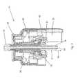
- FIG. 1shows a section through an inventive closure 1 in a delivery position.
- the closure 1comprises a connecting element 2 to a container.
- the connecting element 2is formed by a thread, which is engageable in a matching mating thread of a container.
- the closure 1comprises a sealing device 3 which seals access to the interior of the container prior to initial use.
- the closure 1further comprises an interface 4, which is connectable to an adapter.
- the interface 4comprises a coupling receptacle 5 into which a coupling element of an adapter can be engaged.
- the coupling receptacle 5simultaneously represents a breakthrough element for breaking the seal of the sealing device 3.
- the coupling receptacle 5is designed to be displaceable along a longitudinal axis 11 in the direction of the container and thus penetrates into the sealing device 3 and breaks the seal.
- the sealing device 3may comprise a further predetermined breaking point (see FIGS. 5 and 6 ).
- the coupling receptacle 5furthermore comprises eight engagement grooves 12 into which a matching coupling element with eight or fewer engagement elements can engage. Such a connection allows a fitting and orientation accurate and reduced in-game connection between an adapter and a closure 1.
- the interface 4further comprises fixing elements 13 for an adapter. Below the sealing device 3, in a contact area between the container upper edge and sealing device 3, a sealing element 35 is arranged, which is formed by a PTFE film ring.
- the interface 4further comprises perforation aids 36, which are aligned with predetermined breaking points of the sealing device 3.
- the closure 1also comprises a cover element 6, which is hinged on the closure.
- the closure 1further comprises a break element 7, which indicates a first opening of the lid.
- the lid member 6is removably formed. By such a cover element 6, the closure 1 can be closed again even after the opening of the sealing device 3.
- the closure 1further comprises a fixing element 10 for the cover element, which fixes the interface 4 before use. After removal of the fixing element 10, which is removed by tearing off the closure, the coupling receptacle 5 can be moved along the longitudinal axis 11 and thus the sealing device 3 are broken.
- a first part of the sealing device 3is displaced in the direction of the container along the longitudinal axis 11.
- This displacement channels 9are opened, can be supplied through the air into the container.
- the air that can be passed through channels 9 in the containeris previously cleaned by filter element 8. There is thus no direct contact between the contents of the container and the outside air.
- FIG. 2shows the shutter 1 off FIG. 1 in a use position.
- the coupling receptacle 5is lowered.
- the seal of the sealing device 3is broken and access to the interior of a container is made possible, so that fluid can be conducted through the closure.
- the channel 9is also accessible, so that air which has been passed through the filter element 8, can penetrate into the container.
- the closure 1further has snapper 37, which fix the closure after screwing onto a container. Thus, the closure can be difficult or impossible to remove from the container.
- the closure 1further has an interface 4, with a coupling receptacle 5, in the coupling element of an adapter can be inserted.
- the fixing element 10see FIG.
- the coupling receptacle 5has an inner at least partially conically converging region, so that a coupling element of an adapter is easy to insert and center. Furthermore, five snap elements 38 are formed on the coupling receptacle, which fix the coupling receptacle 5 in the use position; a different number of snap elements 38 is of course possible.
- FIG. 3shows a section through an adapter 14 in the coupled state.
- the adapter 14comprises an interface 16 to a closure and a connection point 15 to a device such as an evaluation unit.
- the interface 16 to a closure(see FIG. 1 and 2 ) comprises a coupling element 17, which has engagement elements 18 along its circumference.
- the engaging elements 18are in insertion grooves 12 (see FIG. 1 ) of a closure insertable.
- the interface 16is displaceable in the insertion direction 19 within the adapter 14 educated.
- the coupling element 17has at its tip in the insertion direction 19, a sealing surface 39, which allows removal of a fluid from a container via a closure 1 without leaks, losses or external contamination.
- sealing elements 40are formed on the coupling element 17, which allow a hermetic air seal at a connection of the adapter 14 with a closure.
- the movement of the coupling element 17 relative to the adapter 14is limited by lever elements 20 in its extension and controlled.
- the interface 16 to a closurefurther comprises fastening elements 21, the adapter 14 releasably connected to a closure 1 (see FIG. 1 or 2 ) connect.
- the adapter 14further comprises a readout element 22 for data of a shutter 1 (see FIG. 1 or 2 ) on.
- the readout elementcan preferably read out RFID data.
- data of a shuttercan be passed directly through the adapter 14 to a device.
- the adapter 14also has a display element 23 (see also FIG.
- FIG. 4shows a section through an adapter 14 as in FIG. 3 , but in a decoupled state.
- the adapter 14is analogous to the description of FIG. 3 educated.
- the interface 16is lowered to a shutter in the direction of insertion direction 19.
- the interface 16comprises a coupling element 17, which has a tubular cavity 41 for the passage of fluid inside. This cavity 41 extends into the connection point 15, so that the Fluid can be further promoted in a device.
- the interface 16furthermore has a latching element 42.
- FIG. 5shows a section through a sealing device according to the invention in a sealed state.
- the sealing device 3has a break element 24 and a fluid connection element 25.
- the break element 24has sealing flaps 28, which can be broken by means of a piercing element in a penetration direction 26.
- the sealing device 3is provided with a predetermined breaking point 27 arranged on the circumference.
- the predetermined breaking point 27divides the fracture element 24 into a first part 43 and a second part 44. Such a predetermined breaking point can be provided, but is not absolutely necessary.
- FIG. 6shows the sealing device 3 from FIG. 5 with broken-off sealing flaps 28.
- the sealing flaps 28are triangular in shape and remain fixed to the sealing device 3 along the circumference of the opening.
- the predetermined breaking point 27is not broken at this stage. To achieve the full use position, the predetermined breaking point 27 is broken along the circumference of the sealing device 3 and the first part 43 of the sealing device 3 is partially inserted into the second part 44 of the sealing device 3.
- FIG. 7shows a section through a sealing device 3 according to FIG. 5 with a piercing element in a delivery position.
- the piercing elementis through the coupling receptacle 5 (see FIG. 1 or 2 ) formed and pierces the sealing flaps 28 in the penetration direction 26.
- the coupling receptacle 5at its front tip perforation 36, which fit accurately between each two sealing flaps and so break the sealing flaps.
- the fluid connection element 25has a removal hose 45 which preferably extends to the bottom of the container in which the closure with the sealing device is arranged.
- FIG. 8shows the sealing device 3 with the coupling device 5 from FIG. 7 in a use position.
- the coupling receptacle 5is displaced in the direction of the piercing direction 26 and has broken the sealing flaps 28.
- the sealing flaps 28remain attached to the sealing device 3, however, lie laterally against the coupling receptacle.
- the coupling receptacle 5furthermore has snap elements 38, which engage in undercuts of the sealing device 3, so that the coupling receptacle 5 remains fixed in its position.
- FIG. 9shows a display element 23, the coupling state of an adapter 14 (see FIG. 3 and 4 ) and a closure 1 (see FIG. 1 and 2 ).
- the display element 23has a display body 29 and a light coupling device 30.
- the coupled-in lightfor example LED light
- the light guide members 31are recesses in the display body 29 made of transparent polyethylene terephthalate (PET).
- PETtransparent polyethylene terephthalate
- the shapes of the light-guiding elements 31are designed so that the light is distributed as evenly as possible in the display body 29.
- the lightis thus deflected substantially by 90 °, wherein the deflection surfaces are not grades but slightly curved.
- the display body 29has an upper side 32 and a lower side 33.
- the bottom 33is formed inclined at an angle 34 compared to the top 32.
- the angle 34is 12 °.
- the display body 29has a round shape and a flange-like protuberance on the top 32 in order to optimize the visibility.
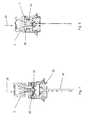
- FIG. 10shows a section through a closure with a container 46 in a use position and an adapter in a decoupled state.
- the adapter systemconsists of a closure 1 (see FIG. 1 and 2 ) and an adapter 14 (see FIG. 3 and 4 ).
- FIG. 11shows a section through an adapter system on a container 46 in a use position.
- FIG. 12 . 13 . 14show the closure FIG. 2 in sectional views showing the air supply through the shutter 1.
- outside airis in each case diverted so that no outside air can pass directly through the closure.
- FIG. 12shows the outside air 48, which can penetrate only up to a sealing element 47 in the closure. From there, the outside air 48 is passed through the filter element 8, which represents in particular an absorber element, so that only purified air 49 can penetrate into the container 46.
- FIG. 13shows a second cut surface (with respect to the position see FIG. 14 ), through which the flow of air is more accurately represented.
- the outside air 48is passed through sealing elements 47 in a lateral channel 9 a and from there into the filter element 8, which is at least partially disposed on the circumference of the closure 1.
- the airis filtered through the filter element and introduced into channel 9 b, through which the air is passed into the interior of the closure 1 in the container 46.
- FIG. 14shows a horizontal section through the closure 1 FIG. 13 ,
- the circulation of airpasses through channel 9a in the filter element 8 at the periphery of the closure 1 through channel 9b in the container 46 (see FIG. 13 ).
Landscapes
- Health & Medical Sciences (AREA)
- Chemical & Material Sciences (AREA)
- Clinical Laboratory Science (AREA)
- Chemical Kinetics & Catalysis (AREA)
- Engineering & Computer Science (AREA)
- General Health & Medical Sciences (AREA)
- Mechanical Engineering (AREA)
- Hematology (AREA)
- Analytical Chemistry (AREA)
- Public Health (AREA)
- Life Sciences & Earth Sciences (AREA)
- Animal Behavior & Ethology (AREA)
- Heart & Thoracic Surgery (AREA)
- Veterinary Medicine (AREA)
- Pulmonology (AREA)
- Anesthesiology (AREA)
- Biomedical Technology (AREA)
- Pharmacology & Pharmacy (AREA)
- Closures For Containers (AREA)
- Containers And Packaging Bodies Having A Special Means To Remove Contents (AREA)
Abstract
Translated fromGermanDescription
Translated fromGermanDie Erfindung betrifft einen Verschluss für einen Behälter, einen Adapter für einen Verschluss, ein Adaptersystem, ein Verfahren zum Entnehmen eines Fluids aus einem Behälter, ein Anzeigeelement zur Anzeige eines Funktionszustandes, eine Versiegelungsvorrichtung sowie die Verwendung eines Adapters und/oder eines Verschlusses gemäss den Oberbegriffen der unabhängigen Ansprüche.The invention relates to a closure for a container, an adapter for a closure, an adapter system, a method for removing a fluid from a container, a display element for displaying a functional state, a sealing device and the use of an adapter and / or a closure according to the preambles the independent claims.
Insbesondere im Rahmen von Laboranwendungen ist die Prozesssicherheit sowie die Prozessqualität bei der Verwendung von verschiedensten Fluiden essenziell wichtig. Des Weiteren ist es vorteilhaft, wenn der Bedienkomfort für den Anwender erhöht ist, welches ebenfalls zur Prozesssicherheit beiträgt.Particularly in the context of laboratory applications, process reliability and process quality when using a wide variety of fluids are essential. Furthermore, it is advantageous if the ease of use is increased for the user, which also contributes to process safety.
Bisherige Verschlüsse von Behältern für Fluide im Laborbereich ermöglichen ein sicheres Verschliessen und Öffnen des Behälters, jedoch können Verunreinigungen durch beispielsweise Luftzufuhr entstehen. Des Weiteren ist die Verbindung eines Behälters mit einem Gerät, welches das Fluid verwendet, oftmals kompliziert herzustellen, wodurch die Handhabung erschwert ist.Previous closures of containers for fluids in the laboratory allow a safe closure and opening of the container, however, contamination may result from, for example, air supply. Furthermore, the connection of a container to a device using the fluid is often complicated to manufacture, making handling difficult.
Es ist daher Aufgabe der vorliegenden Erfindung, die Nachteile des Standes der Technik zu vermeiden und insbesondere einen Verschluss, einen Adapter, ein Verfahren zum Entnehmen eines Fluids aus einem Behälter, ein Anzeigeelement, eine Versiegelungsvorrichtung sowie die Verwendung eines Adapters und/oder eines Verschlusses zu schaffen, die eine leichte und sichere Entnahme eines Fluids aus einem Behälter ermöglichen und den Aufwand und die Fehlerquellen eines Anwenders verringern.It is therefore an object of the present invention to avoid the disadvantages of the prior art, and in particular a closure, an adapter, a method for removing a fluid from a container, a display element, a sealing device and the use of an adapter and / or a closure create an easy and safe removal of a fluid from a container and reduce the effort and sources of error of a user.
Zur Lösung der Aufgabe führt ein Verschluss für einen Behälter, der ein Verbindungselement zur Verbindung des Verschlusses mit einem Behälter und eine Versiegelungsvorrichtung zum Versiegeln des Zugangs zu einem Behälterinhalt umfasst. Des Weiteren umfasst der Verschluss eine Schnittstelle zu einem Adapter mit einer Kupplungsaufnahme, wobei der Verschluss eine Lieferposition und eine Gebrauchsposition aufweist. In der Lieferposition ist die Versiegelungsvorrichtung gas- und flüssigkeitsdicht verschlossen, wobei die Versiegelungsvorrichtung in einer Gebrauchsposition geöffnet ist. Ein mit einem solchen Verschluss ausgestatter Behälter ist nach aussen hin im Wesentlichen gas- und flüssigkeitsdicht verschlossen, wie nachstehend noch im Detail erläutert ist.To achieve the object, a closure for a container, which comprises a connecting element for connecting the closure with a container and a sealing device for sealing the access to a container contents. Furthermore, the closure comprises an interface to an adapter with a coupling receptacle, wherein the closure has a delivery position and a use position. In the delivery position, the sealing device is closed gas-tight and liquid-tight, wherein the sealing device is open in a use position. A container provided with such a closure is closed to the outside substantially gas and liquid-tight, as will be explained in detail below.
Ein derartiger Verschluss ermöglicht das kontaminations- und leckagefreie Transportieren eines Fluids in einem Behälter sowie das leichte Verbinden mit einem Adapter, wobei der Verschluss beim oder vor dem Verbinden mit einem Adapter geöffnet wird.Such a closure allows contamination-free and leak-free transport of a fluid in a container and easy connection to an adapter, wherein the closure is opened during or before connection to an adapter.
Die Lieferposition des Verschlusses umfasst eine verschlossene Versiegelung sowie bevorzugt einen Verschluss von Luftzuführungs- und Luftabführungskanälen.The delivery position of the closure includes a sealed seal, and preferably a closure of air supply and exhaust ducts.
In der Gebrauchsposition ist die Versiegelung geöffnet und ein Fluid aus einem Behälter kann durch den Verschluss entnommen werden. Bevorzugt kommt das Fluid jedoch nicht mit Aussenluft direkt in Verbindung, wie nachfolgend noch erläutert wird.In the use position, the seal is opened and fluid from a container can be removed through the closure. However, the fluid preferably does not come into direct contact with outside air, as will be explained below.
Das Verbindungselement kann ein Gewinde umfassen.The connecting element may comprise a thread.
Ein Gewinde ermöglicht das Befestigen des Verschluss einfach und unkompliziert auf ein passendes Gegengewinde eines Behälters. Des Weiteren sind selbstverständlich auch Bajonettverschlüsse oder Schnappverschlüsse möglich.A thread allows attaching the closure easily and easily to a matching mating thread of a container. Furthermore, of course, bayonet locks or snaps are possible.
Der Verschluss kann ein Deckelelement zum Öffnen und Verschliessen des Verschlusses umfassen, wobei das Deckelelement bevorzugt durch ein Bruchelement sicherbar ist, welches ein erstmaliges Öffnen anzeigt.The closure may comprise a lid member for opening and closing the closure, the lid member preferably being securable by a break element indicating initial opening.
Ein derartiges Deckelelement ermöglicht ein Verschliessen und Wiederöffnen des Verschlusses nach dem Öffnen der Versiegelungsvorrichtung in einer Gebrauchsposition. Ein weiteres Bruchelement an dem Deckelelement zum Anzeigen eines erstmaligen Öffnens macht den Verschluss manipulierungssicher.Such a lid member allows a closure and reopening of the closure after opening the sealing device in a use position. Another break element on the lid member for indicating initial opening makes the closure tamper-proof.
Der Verschluss kann ein Filterelement umfassen, durch welches, insbesondere in der Gebrauchsposition, Aussenluft von aussen durch den Verschluss in einen Behälter leitbar ist.The closure may comprise a filter element, through which, especially in the use position, outside air can be conducted from the outside through the closure into a container.
Um Fluid aus dem Behälter entnehmen zu können, ist eine Luftzufuhr von Vorteil, um einen Druckausgleich zu ermöglichen. Der Einsatz eines Filterelements verhindert die Kontamination des Inhalts des Behälters durch direkte Aussenluft und ermöglicht somit ein genaues und qualitativ hochwertiges Arbeiten.To be able to remove fluid from the container, an air supply is advantageous in order to allow a pressure equalization. The use of a filter element prevents the contamination of the contents of the container by direct external air and thus allows an accurate and high quality work.
Filterelemente sind bevorzugt mit einem Material ausgestattet, welches dazu geeignet ist, Anteile aus der Umgebungsluft zu entfernen, welche eine Veränderung des Behälterinhalts bewirken können. Das jeweilige Material wird hierbei in fachüblichen Routinemassnahmen auf den jeweiligen Behälterinhalt abgestimmt. Typische Beispiele geeigneter Materialien sind Atemkalk (eine auch als Natronkalk bekannte Mischung aus Calciumhydroxid Ca(OH)2 und Natriumhydroxid NaOH; oder auch eine Mischung aus Kaliumhydroxid KOH und Bariumhydroxid Ba(OH)2); Partikelfilter; Molekularsiebe, Silicagel.Filter elements are preferably equipped with a material which is suitable for removing portions of the ambient air, which may cause a change in the container contents. The respective material is matched to the respective container contents in routine routine measures. Typical examples of suitable materials are soda lime (also known as soda lime mixture of calcium hydroxide Ca (OH)2 and sodium hydroxide NaOH, or a mixture of potassium hydroxide KOH and barium hydroxide Ba (OH)2 ); particulate filter; Molecular sieves, silica gel.
Kanäle zur Zuführung und Abführung von Luft können in dem Verschluss verschliessbar ausgebildet sein, bevorzugt durch die Versiegelungsvorrichtung verschliessbar, wobei die Versiegelungsvorrichtung die Kanäle insbesondere bevorzugt in der Lieferposition mit geschlossener Versiegelung verschliesst. Definierte Kanäle zur Zu- und Abführung von Luft ermöglichen ein besonders sicheres und kontaminationsfreies Arbeiten. Die Luft wird bevorzugt durch ein Filterelement geleitet, bevor sie mit dem Behälterinhalt in Kontakt kommt. Des Weiteren sind die Kanäle in einer Lieferposition bevorzugt verschlossen und werden erst in einer Gebrauchsposition geöffnet.Channels for the supply and removal of air may be designed to be closable in the closure, preferably closable by the sealing device, wherein the sealing device closes the channels particularly preferably in the delivery position with closed seal. Defined channels for the supply and removal of air allow a particularly safe and contamination-free work. The air is preferably passed through a filter element before coming in contact with the contents of the container. Furthermore, the channels are preferably closed in a delivery position and are only opened in a use position.
Die Kanäle zur Zuführung- und Abführung von Luft in dem Verschluss können besonders bevorzugt als weibliche Lueranschlüsse (mit einem Innenkonus) oder mit einem Gewinde ausgestattet sein. So kann im Falle eines abnehmbaren Filterelements auch ohne angeschlossenes Filterelement bspw. ein Schlauch für die Zufuhr von Schutzgas besonders einfach an dem Verschluss angebracht werden.The channels for the supply and discharge of air in the closure may be particularly preferably equipped as female Lueranschlüsse (with an inner cone) or with a thread. Thus, in the case of a removable filter element, for example, without a connected filter element, for example, a hose for the supply of protective gas can be attached to the closure in a particularly simple manner.
Der Verschluss kann ein Fixierungselement umfassen, welches den Verschluss in einer Lieferposition fixiert, wobei das Fixierungselement lösbar ausgebildet ist. Das Fixierungselement ist insbesondere bevorzugt zerstörbar lösbar ausgebildet und nach der Lösung und bevorzugt Entfernung des Fixierungselements ist der Verschluss in eine Gebrauchsposition bringbar.The closure may comprise a fixing element which fixes the closure in a delivery position, wherein the fixing element is detachably formed. The fixing element is particularly preferably detachably designed detachable and after the solution and preferably removal of the fixing element, the closure can be brought into a position of use.
Ein derartiges Fixierungselement verhindert ein vorzeitiges Erreichen der Gebrauchsposition des Verschlusses, falls dies noch nicht gewollt ist. Des Weiteren stellt ein derartiges Fixierungselement eine visuelle Anzeige des Öffnungszustandes und/oder der Liefer- beziehungsweise Gebrauchsposition des Verschlusses dar. Somit wird ein fehlerfreies Arbeiten leicht ermöglicht.Such a fixing element prevents premature reaching the use position of the closure, if this is not yet wanted. Furthermore, such a fixing element a visual indication of the opening state and / or the delivery or use position of the closure. Thus, a flawless working is easily possible.
Der Verschluss kann einen Datenträger umfassen, bevorzugt einen Datenträger mit zerstörbarem Datenübertragungselement, insbesondere bevorzugt einen RFID-Chip.The closure may comprise a data carrier, preferably a data carrier with a destructible data transmission element, in particular preferably an RFID chip.
Ein Datenträger ermöglicht die automatische Erkennung des Verschlusses sowie der Daten, die auf dem Datenträger gespeichert sind, wie beispielsweise Daten des zugehörigen Behälters sowie des Inhalts des Behälters. Dies führt zu einer sicheren Arbeitsweise, da wichtige Daten übertragen werden können. So kann beispielsweise der Inhalt des Behälters fehlerfrei erkannt werden. Des Weiteren können Daten wie beispielsweise Volumen, Haltbarkeitsdaten oder entnommene Mengen über den Datenträger festgestellt beziehungsweise auf diesem gespeichert werden. Dies führt zu qualitativ hochwertigen Resultaten. Der Datenträger kann optisch und/oder elektronisch ausgebildet sein.A data carrier allows the automatic detection of the shutter and the data stored on the data carrier, such as data of the associated container and the contents of the container. This leads to a secure way of working, as important data can be transmitted. For example, the contents of the container can be recognized without errors. Furthermore, data such as volume, shelf life data or withdrawn amounts can be detected via the data carrier or stored on this. This leads to high quality results. The data carrier can be designed optically and / or electronically.
Die Kupplungsaufnahme kann entlang einer Längsachse des Verschlusses von einer Lieferposition in eine Gebrauchsposition bewegbar ausgebildet sein.The coupling receptacle can be designed to be movable along a longitudinal axis of the closure from a delivery position into a use position.
Durch eine Bewegbarkeit der Kupplungsaufnahme kann die Gebrauchsposition bei dem Einkuppeln eines passenden Kupplungselements für die Kupplungsaufnahme erreicht werden. Das Öffnen der Versiegelungsvorrichtung kann insbesondere unabhängig vom Einsatz des Adapters erfolgen, vorzugsweise durch einfaches Herunterdrücken des Verschlusses, wobei ein passender Adapter dann in einem nachfolgenden Schritt angebracht wird.By a mobility of the coupling receptacle, the use position can be achieved when engaging a suitable coupling element for the coupling receptacle. The opening of the sealing device can in particular be carried out independently of the use of the adapter, preferably by simply pressing down the closure, wherein a suitable adapter is then attached in a subsequent step.
Der Verschluss ist in einer Lieferposition bevorzugt gasdicht und flüssigkeitsdicht verschlossen. In einer Gebrauchsposition kann Fluid aus dem Behälter durch den Verschluss geführt werden. Nichtsdestotrotz bleibt die Gaszufuhr, beziehungsweise Luftzufuhr durch ein Filterelement kontrolliert, so dass keine Kontaminationen des Inhalts des Behälters auftreten können.The closure is preferably gas-tight and liquid-tight in a delivery position. In a use position, fluid may be passed out of the container through the closure. Nevertheless, the gas supply or air supply is controlled by a filter element, so that no contamination of the contents of the container can occur.
Die Versiegelungsvorrichtung kann nach Entfernen des Fixierungselements und Herunterdrücken des Deckels geöffnet, bevorzugt gebrochen werden, wobei der Verschluss nach dem Aufbrechen der Versiegelungsvorrichtung in der Gebrauchsposition fixierbar ist.After the fixing element has been removed and the lid has been pressed down, the sealing device can be opened, preferably broken, whereby the closure can be fixed in the use position after the sealing device has broken open.
Somit bleibt die Kupplungsaufnahme nach dem Aufbrechen der Versiegelung in einer Gebrauchsposition und ist erkennbar für den Benutzer bereits gebraucht. Dies erhöht die Sicherheit und macht die Verwendung des Verschlusses für den Anwender einfach und zuverlässig.Thus, the coupling receptacle remains after the breaking of the seal in a use position and is recognizable to the user already needed. This increases safety and makes the use of the closure easy and reliable for the user.
In der Gebrauchsposition ist die insbesondere durch ein Filterelement gereinigte Luft durch den Verschluss leitbar.In the use position, the air, in particular cleaned by a filter element, can be conducted through the closure.
Die Zuführung von Luft ermöglicht einen Druckausgleich und erleichtert somit das Entnehmen von Fluid aus dem Behälter unter kontaminationsfreien Bedingungen.The supply of air allows pressure equalization and thus facilitates the removal of fluid from the container under contamination-free conditions.
Die Kupplungsaufnahme kann Eingriffsnuten umfassen, bevorzugt acht Eingriffsnuten. Die Ausbildung von Eingriffsnuten ermöglicht ein passgenaues Einführen eines Kupplungselements sowie eine dezidierte Ausrichtung eines Adapters auf dem Verschluss. Des Weiteren ist die Kraftübertragung von Adapter auf den Verschluss optimiert.The coupling receptacle may comprise engagement grooves, preferably eight engagement grooves. The formation of engagement grooves allows a precise insertion of a coupling element and a dedicated orientation of an adapter on the closure. Furthermore, the power transmission from adapter to the closure is optimized.
Der Verschluss kann zumindest ein Fixierungselement umfassen, an welchem ein Adapter befestigbar ist.The closure may comprise at least one fixing element to which an adapter can be fastened.
Ein derartiges Fixierungselement kann eine Hinterschneidung oder Kante oder Haltefläche umfassen, die von Eingriffselementen eines Adapters umgriffen werden können. Somit ist ein Adapter sicher auf dem Verschluss fixiert.Such a fixing element may comprise an undercut or edge or holding surface, which can be encompassed by engagement elements of an adapter. Thus, an adapter is securely fixed on the closure.
Zur Lösung der Aufgabe führt weiterhin ein Behälter, der mit einem Verschluss wie vorhergehend beschrieben verbunden, bevorzugt nach aussen hin im Wesentlichen gas- und flüssigkeitsdicht verschlossen ist.To achieve the object further leads to a container which is connected to a closure as described above, preferably closed to the outside substantially gas and liquid-tight.
Ein derartiger Behälter kann leicht und sicher mit einem Adapter verbunden werden und ermöglicht ein sicheres Aufbewahren sowie kontaminationsfreies und leichtes Entnehmen eines Fluids aus dem Behälter.Such a container can be easily and safely connected to an adapter and allows safe storage and contamination-free and easy removal of fluid from the container.
Zur Lösung der Aufgabe führt weiterhin ein Adapter für einen Verschluss, bevorzugt ein Verschluss wie vorhergehend beschrieben, der eine Verbindungsstelle zu einem Gerät, bevorzugt eine Auswertungseinheit und eine Schnittstelle zu einem Verschluss umfasst. Die Schnittstelle umfasst weiterhin ein Kupplungselement, welches mit einer Kupplungsaufnahme eines Verschlusses in Eingriff bringbar ist, so dass ein Fluidstrom durch den Adapter erzeugbar ist, ohne einen direkten Kontakt von Aussenluft und Fluid.To achieve the object further leads an adapter for a closure, preferably a closure as described above, comprising a connection point to a device, preferably an evaluation unit and an interface to a closure. The interface further comprises a coupling element, which is engageable with a coupling receptacle of a closure, so that a fluid flow through the adapter can be generated, without a direct contact of outside air and fluid.
Ein derartiger Adapter ermöglicht das kontaminationsfreie und leichte Entnehmen eines Fluid aus einem Behälter und das Weiterführen in ein Gerät, welches das Fluid benötigt. Der Arbeitsaufwand für einen Benutzer wird vereinfacht und verringert und die Prozesssicherheit steigt.Such an adapter allows the contamination-free and easy removal of a fluid from a container and the continuation in a device which requires the fluid. The workload for a user is simplified and reduced, and process reliability increases.
Das Kupplungselement kann Eingriffselemente umfassen, bevorzugt acht Eingriffselemente, die in Eingriffnuten einer Kupplungsaufnahme eines Verschlusses einführbar sind, wie nachfolgend noch im Detail anhand von Ausführungsbeispielen erläutert wird.The coupling element may comprise engagement elements, preferably eight engagement elements, which are insertable into engagement grooves of a coupling receptacle of a closure, as will be explained in detail below with reference to exemplary embodiments.
Die Ausbildung von Eingriffelementen ermöglicht ein pass- und orientierungsgenaues, einfaches und sicheres Einführen des Kupplungselements in die Kupplungsaufnahme eines Verschlusses und somit ein sichere Verbindung von Adapter und Verschluss.The formation of engagement elements allows a fitting and orientation accurate, simple and secure insertion of the coupling element in the coupling receptacle of a closure and thus a secure connection of adapter and closure.
Besonders bevorzugt sind die Eingriffsnuten einer Kupplungsaufnahme eines Verschlusses in einem sich konisch in Richtung des Behälters verjüngenden Bereich dieser Kupplungsaufnahme angeordnet. Besonders bevorzugt laufen diese Eingriffsnuten im weiteren Teil des sich konisch in Richtung des Behälters verjüngenden Bereichs flach aus. Es hat sich gezeigt, dass hierdurch ein besonders vorteilhafter Kompromiss aus einfacher Handhabbarkeit und Funktionssicherheit sichergestellt werden kann.Particularly preferably, the engagement grooves of a coupling receptacle of a closure are arranged in a conically tapering in the direction of the container portion of this coupling receptacle. Particularly preferably, these engagement grooves run flat in the further part of the conically tapered region in the direction of the container. It has been shown that in this way a particularly advantageous compromise of easy handling and functional reliability can be ensured.
Das Kupplungselement kann relativ zum Adapter bewegbar ausgebildet sein, bevorzugt entlang der Achse einer Einführungsrichtung des Adapters in einen Verschluss bewegbar.The coupling element may be designed to be movable relative to the adapter, preferably movable along the axis of an insertion direction of the adapter into a closure.
Ein bewegbares Kupplungselement ermöglicht die passgenaue Verbindung zwischen Kupplungselement und Kupplungsaufnahme unabhängig von der Befestigung des Adapters am Verschluss. Des Weiteren wird eine zuverlässige Dichtung zwischen dem Kupplungselement und einem Fluidentnahmeschlauch des Verschlusses durch Flächenpressung ermöglicht. Der Fluidentnahmeschlauch ist hierbei auskragend ausgebildet, sodass das Kupplungselement auf dem Kragen zum Anliegen kommt. Auf ein zusätzliches Dichtungselement kann daher in besonders vorteilhafter Weise verzichtet werden. Der Adapter kann Hebelelemente umfassen, durch die das Kupplungselement relativ zum Adapter bewegbar ist. Die Verwendung von Hebelelementen definiert die Beweglichkeit des Kupplungselements relativ zum Adapter und ermöglicht somit ein passgenaues Verbinden von Adapter und Verschluss.A movable coupling element allows the exact connection between coupling element and coupling receptacle regardless of the attachment of the adapter to the closure. Furthermore, a reliable seal between the coupling element and a fluid extraction tube of the closure is made possible by surface pressure. The fluid removal hose is formed projecting, so that the coupling element comes to rest on the collar. An additional sealing element can therefore be dispensed with in a particularly advantageous manner. The adapter may comprise lever elements by which the coupling element is movable relative to the adapter. The use of lever elements defines the mobility of the coupling element relative to the adapter and thus allows a precise connection of adapter and closure.
Der Adapter kann Befestigungselemente umfassen, die mit einem Fixierungselement eines Verschlusses in Eingriff bringbar sind, wobei die Befestigungselemente bevorzugt mechanisch lösbar ausbildet sind. Insbesondere bevorzugt sind die Befestigungselemente während der Bewegung des Kupplungselements lösbar ausgebildet.The adapter may comprise fastening elements, which can be brought into engagement with a fixing element of a closure, wherein the fastening elements are preferably made mechanically detachable. Particularly preferably, the fastening elements are detachably formed during the movement of the coupling element.
Die Befestigungselemente ermöglichen eine passgenaue Fixierung des Adapters auf einem Verschluss und ein Lösen. Die Befestigungselemente sind bevorzugt Schnappelemente, die auf eine Hinderschneidung eines Verschlusses eingreifen. Somit ist der Adapter sicher mit dem Verschluss verbunden.The fasteners allow a custom-fit fixation of the adapter on a closure and a release. The fastening elements are preferably snap-action elements which engage in an obstruction of a closure. Thus, the adapter is securely connected to the closure.
Die Verbindungsstelle kann eine Gewindekupplung umfassen.The joint may include a threaded coupling.
Ein Gewindekupplung ermöglicht eine schnelle und sichere Verbindung des Adapters mit einem Gerät, welches Fluid aus einem Behälter mit einem Verschluss benötigt.A threaded coupling allows a quick and secure connection of the adapter to a device that requires fluid from a container with a closure.
Der Adapter kann ein Ausleselement für Daten umfassen, bevorzugt eine Ausleseelektronik für einen RFID-Chip.The adapter may comprise a read-out element for data, preferably a read-out electronics for an RFID chip.
Durch ein Ausleseelement am Adapter kann der Adapter Daten des Verschlusses und somit, falls eingespeichert, auch des Behälters und des im Behälter befindlichen Fluids auslesen. Dies führt zu höherer Prozesssicherheit, da Fehler durch den Benutzer ausgeschlossen sind.By means of a read-out element on the adapter, the adapter can read out data of the closure and thus, if stored, also of the container and of the fluid in the container. this leads to higher process reliability because errors are excluded by the user.
Das Ausleseelement kann eine Schreibfunktion für Daten aufweisen. Eine derartige Schreibfunktion ermöglicht das Kennzeichnen des Verschlusses und somit auch des Behälters durch den Adapter, so dass beispielsweise Datum der Benutzung, Zeitpunkte von An- und Abkoppeln des Verschlusses oder Öffnen oder Verbrauch an Fluid festgehalten werden können.The readout element may have a write function for data. Such a writing function allows the closure and thus also the container to be identified by the adapter so that, for example, the date of use, times of coupling and uncoupling of the closure or opening or consumption of fluid can be recorded.
Dies führt zu erhöhter Prozesssicherheit.This leads to increased process reliability.
Der Adapter kann ein Anzeigelement aufweisen. Insbesondere kann der Adapter ein Anzeigelement aufweisen wie nachfolgend beschrieben. Ein derartiges Anzeigelement ermöglicht das Anzeigen einer Verbindung von Adapter und Verschluss.The adapter may have a display element. In particular, the adapter may have a display element as described below. Such a display element allows the connection of the adapter and the closure to be displayed.
Zur Lösung der Aufgabe führt weiterhin ein Adaptersystem für einen Behälter, der einen Verschluss sowie einen Adapter wie vorhergehend beschrieben umfasst.To achieve the object further leads to an adapter system for a container comprising a closure and an adapter as described above.
Zur Lösung der Aufgabe führt weiterhin ein Verfahren zum Entnehmen eines Fluid aus einem Behälter, wobei das Fluid durch ein Adaptersystem wie vorhergehend beschrieben geführt wird.To achieve the object further leads to a method for removing a fluid from a container, wherein the fluid is passed through an adapter system as described above.
Ein derartiges Verfahren ermöglicht die sichere und zuverlässige Entnahme von Fluid aus einem Behälter unter kontaminationsfreien Bedingungen.Such a method allows the safe and reliable removal of fluid from a container under contamination-free conditions.
Zur Lösung der Aufgabe führt weiterhin ein Anzeigelement zur Anzeige eines Funktionszustandes, insbesondere eines Kopplungszustandes zwischen einem Verschluss wie vorgehend beschrieben und einem Adapter wie vorhergehend beschrieben. Das Anzeigeelement umfasst zumindest ein Anzeigekörper sowie zumindest eine Lichteinkopplungsvorrichtung zum Einkoppeln von Licht in den Anzeigekörper. Des Weitern sind Lichtlenkelemente zum Verteilen des eingekoppelten Lichts in dem Anzeigekörper ausgebildet, die das eingekoppelte Licht im Anzeigekörper verteilen.To achieve the object further leads a display element for displaying a functional state, in particular a coupling state between a closure as described above and an adapter as described above. The display element comprises at least one display body and at least one Lichteinkopplungsvorrichtung for coupling light into the display body. Furthermore, light-deflecting elements for distributing the coupled-in light are formed in the display body, which distribute the coupled-in light in the display body.
Ein derartiges Anzeigelement zeigt deutlich und zuverlässig den Kopplungszustand zwischen Verschluss und Adapter an, und führt somit zur erhöhten Verwendungssicherheit von Adapter und Verschluss.Such a display element clearly and reliably indicates the coupling state between the closure and the adapter, and thus leads to an increased safety of use of the adapter and the closure.
Die Lichtlenkelemente können Grenzflächen umfassen.The light directing elements may comprise interfaces.
Durch die Verwendung von Grenzflächen wird das Licht gebrochen und somit umgelenkt. Weiterhin sind Grenzflächen einfach und günstig herzustellen. Das Licht wird somit durch den gesamten Anzeigekörper geleitet und die Anzeige ist somit seht deutlich und leicht zu erkennen.Through the use of interfaces, the light is refracted and thus redirected. Furthermore, interfaces are easy and inexpensive to manufacture. The light is thus passed through the entire display body and the display is thus clearly visible and easy to recognize.
Grenzflächen im Rahmen der Anmeldung sind Flächen, an denen sich der Brechungsindex ändert. Alternativ können selbstverständlich auch andere oder zusätzliche reflektive und/oder diffraktive Elemente verwendet werden.Surfaces in the context of the application are areas where the refractive index changes. Alternatively, of course, other or additional reflective and / or diffractive elements may be used.
Der Anzeigekörper kann eine Oberseite und Unterseite umfassen, wobei die Oberseite kreisförmig ausgebildet ist und die Unterseite im Vergleich zur Oberseite in einem Winkel von etwa 8° bis etwa 20°, bevorzugt von etwa 10° bis etwa 15°, besonders bevorzugt von etwas 12° angeordnet ist.The display body may comprise a top and a bottom, wherein the top is circular and the bottom compared to the top at an angle of about 8 ° to about 20 °, preferably from about 10 ° to about 15 °, more preferably from about 12 ° is arranged.
Eine derartige Ausbildung des Anzeigekörpers verbessert die Verteilung des Lichts im Anzeigekörper.Such a design of the display body improves the distribution of light in the display body.
Zur Lösung der Aufgabe führt weiterhin eine Versiegelungsvorrichtung zum Versiegeln eines Behälters, die Bruchelemente zum endgültigen Aufbrechen der Versiegelung durch ein Aufbrechelement zum Durchstossen des Bruchelements in eine Durchstossrichtung umfasst. Des Weiteren umfasst die Versiegelungsvorrichtung ein Fluidanschlusselement zum Herstellen einer Verbindung zu einem Fluid nach dem Aufbrechen der Versiegelung. Zumindest ein Teil des Bruchelements ist entlang der Durchstossrichtung von einer Lieferposition in eine Gebrauchsposition verschiebbar ausgebildet, wobei das Bruchelement bevorzugt in der Lieferposition eine Sollbruchstelle aufweist.To achieve the object, a sealing device for sealing a container, which comprises fracture elements for the final breaking of the seal by a break-off element for piercing the break element in a penetration direction, furthermore results. Furthermore, the sealing device comprises a fluid connection element for establishing a connection to a fluid after the seal has broken open. At least a part of the fracture element is designed to be displaceable along the piercing direction from a delivery position to a use position, the fracture element preferably having a predetermined breaking point in the delivery position.
Die Sollbruchstelle ist bevorzugt am Umfang des Bruchelements angeordnet, so dass nach dem Aufbrechen der Sollbruchstelle das Bruchelement weniger Höhenausdehnung aufweist als in einem Lieferzustand. Die Kraft zum Brechen der Sollbruchstelle ist bevorzugt manuell aufbringbar, etwa in einem Bereich von 15N bis 30N, vorzugsweise etwa 17N bis 25N, besonders bevorzugt etwa 20N. In besonders bevorzugten Ausführungsformen führt ein darüber hinausgehender Druck zu einem fühlbaren Einschnappen; der hierfür aufzuwendende Druck sollte etwa in einem Bereich von 30N bis 50N, vorzugsweise etwa 35N bis 45N, besonders bevorzugt bei etwa 40N liegen. Durch diese haptische Rückkopplung wird die Handhabbarkeit weiter verbessert.The predetermined breaking point is preferably arranged on the circumference of the fracture element, so that after fracture of the predetermined breaking point, the fracture element has less height extent than in a delivery condition. The force for breaking the predetermined breaking point is preferably manually applicable, for example in a range of 15N to 30N, preferably about 17N to 25N, more preferably about 20N. In particularly preferred embodiments, excess pressure results in tactile snapping; the pressure to be applied should be approximately in the range of 30N to 50N, preferably about 35N to 45N, more preferably about 40N. By this haptic feedback the handling is further improved.
Eine derartige Ausbildung der Versiegelungsvorrichtung ermöglicht ein sicheres Anzeigen des Öffnungszustandes und gleichzeitig eine optimale Positionierung des Fluidanschlusselements zur Erstellung einer Fluidverbindung zwischen Fluidanschlusselement und einem Kupplungselement.Such a design of the sealing device enables a reliable indication of the opening state and at the same time an optimal positioning of the fluid connection element for establishing a fluid connection between the fluid connection element and a coupling element.
Das Bruchelement kann nach dem Aufbrechen der Sollbruchstelle einen ersten verschiebbaren und einen zweiten fixen Teil umfassen. Der erste verschiebbare Teil ist in Durchstossrichtung verschiebbar.The break element may comprise a first displaceable and a second fixed part after breaking the predetermined breaking point. The first displaceable part is displaceable in the direction of penetration.
Somit ist ein vollständiges Brechen der Sollbruchstelle entlang des gesamten Umfangs klar erkennbar. Dies führt zu einer verbesserten Prozesssicherheit, da die Höhe der Versiegelungsvorrichtung sich entlang des gesamten Umfangs ändert und somit detektierbar ist.Thus, a complete breaking of the predetermined breaking point along the entire circumference is clearly visible. This leads to an improved process reliability, since the height of the sealing device changes along the entire circumference and is thus detectable.
Das Bruchelement kann weiterhin Siegelklappen aufweisen, die zwischen einander Sollbruchstellen aufweisen und bevorzugt jeweils dreieckig ausgebildet sind.The fracture element may further comprise sealing flaps which have predetermined breaking points between each other and are preferably triangular in each case.
Das Vorhandensein von Siegelklappen ermöglicht den endgültigen Zugang zu dem Inneren der Versiegelungsvorrichtung und ermöglichen so in einer Lieferposition eine gas- und flüssigkeitsdichte Ausbildung der Versiegelungsvorrichtung sowie in einer Gebrauchsposition das leichte Einführen eines Kupplungselements zur Entnahme eines Fluid aus einem Behälter.The presence of sealing flaps allows the final access to the interior of the sealing device and thus enables in a delivery position a gas- and liquid-tight design of the sealing device and in a use position, the easy insertion of a coupling element for removing a fluid from a container.
Dreieckige Ausbildung der Siegelklappen bedeutet im Rahmen der Erfindung, dass die Siegelklappen zumindest drei Ecken aufweisen. Es ist hierbei möglich dass die Sehnen des Dreiecks gerundet, gerade oder elliptisch ausgebildet sind.Triangular design of the sealing flaps means in the context of the invention that the sealing flaps have at least three corners. It is possible that the tendons of the triangle are rounded, straight or elliptical.
Ein Adapter wie vorhergehend beschrieben und/oder eine Verschluss wie vorhergehend beschrieben können zum Hindurchführen eines Fluid bei der Entnahme aus einem Behälter verwendet werden.An adapter as previously described and / or a closure as previously described may be used to pass a fluid upon removal from a container.
Die Erfindung wird nachfolgend in Ausführungsbeispielen anhand von Figuren näher erläutert. Dabei zeigt:
- Fig. 1
- Einen Schnitt durch einen erfindungsgemässen Verschluss in einer Lieferposition
- Fig. 2
- Einen Schnitt durch einen erfindungsgemässen Verschluss in einer Gebrauchsposition
- Fig. 3
- Einen Schnitt durch einen erfindungsgemässen Adapter in gekoppelter Position (Verschluss nicht gezeigt)
- Fig. 4
- Einen Schnitt durch den Adapter aus
Fig. 3 in entkoppelter Position (Verschluss nicht gezeigt) - Fig. 5
- Einen Schnitt durch eine erfindungsgemässe Versiegelungsvorrichtung
- Fig. 6
- Einen Schnitt durch die Versiegelungsvorrichtung aus
Fig. 5 mit geöffneten Siegelklappen - Fig. 7
- Einen Schnitt durch eine Versiegelungsvorrichtung gemäss
Fig. 5 mit einem Durchstosselement in einer Lieferposition - Fig. 8
- Einen Schnitt durch eine Versiegelungsvorrichtung gemäss
Fig. 7 in einer Gebrauchsposition - Fig. 9
- Eine Ansicht eines Anzeigeelements
- Fig. 10
- Eine Schnittzeichnung durch einen Verschluss mit einem Behälter in Gebrauchsposition und einem entkoppelten Adapter
- Fig. 11
- Eine Schnittzeichnung durch einen Verschluss mit einem Behälter in Gebrauchsposition und gekoppeltem Adapter.
- Fig. 12
- Eine Schnittzeichnung durch die Mitte eines Verschlusses gemäss
Figur 2 mit Kennzeichnung der Luftzufuhr Figur 13- Eine Schnittzeichnung durch einen Verschluss gemäss
Fig. 12 durch eine zweite Schnittfläche (sieheFigur 14 ) Figur 14- Eine horizontale Schnittzeichnung eines Verschlusses gemäss
Fig. 2 mit Darstellung der Schnittebene vonFig. 13 .
- Fig. 1
- A section through a closure according to the invention in a delivery position
- Fig. 2
- A section through a closure according to the invention in a use position
- Fig. 3
- A section through an inventive adapter in a coupled position (closure not shown)
- Fig. 4
- Make a cut through the adapter
Fig. 3 in decoupled position (shutter not shown) - Fig. 5
- A section through a sealing device according to the invention
- Fig. 6
- A section through the sealing device
Fig. 5 with opened sealing flaps - Fig. 7
- A section through a sealing device according to
Fig. 5 with a piercing element in a delivery position - Fig. 8
- A section through a sealing device according to
Fig. 7 in a use position - Fig. 9
- A view of an ad element
- Fig. 10
- A sectional view through a closure with a container in use position and a decoupled adapter
- Fig. 11
- A sectional view through a closure with a container in use position and coupled adapter.
- Fig. 12
- A sectional drawing through the middle of a closure according to
FIG. 2 with identification of the air supply - FIG. 13
- A sectional drawing through a closure according to
Fig. 12 through a second cut surface (seeFIG. 14 ) - FIG. 14
- A horizontal sectional drawing of a closure according to
Fig. 2 with representation of the cutting plane ofFig. 13 ,
Claims (18)
Translated fromGermanPriority Applications (11)
| Application Number | Priority Date | Filing Date | Title |
|---|---|---|---|
| EP13162169.0AEP2786802A1 (en) | 2013-04-03 | 2013-04-03 | Lock for a container |
| BR112015024980-9ABR112015024980B1 (en) | 2013-04-03 | 2014-04-01 | CLOSING FOR A CONTAINER |
| ES14713863TES2899162T3 (en) | 2013-04-03 | 2014-04-01 | Closure for a container |
| CN201480031876.0ACN105263629B (en) | 2013-04-03 | 2014-04-01 | Closures for containers |
| US14/781,696US10737855B2 (en) | 2013-04-03 | 2014-04-01 | Closure for a container |
| EP21191874.3AEP3928866A1 (en) | 2013-04-03 | 2014-04-01 | Lock for a container |
| EP14713863.0AEP2981356B8 (en) | 2013-04-03 | 2014-04-01 | Closure for a container |
| JP2016505791AJP6412555B2 (en) | 2013-04-03 | 2014-04-01 | Stopper for container |
| RU2015147179ARU2692035C2 (en) | 2013-04-03 | 2014-04-01 | Container cover |
| PCT/EP2014/056491WO2014161831A2 (en) | 2013-04-03 | 2014-04-01 | Closure for a container |
| US16/923,450US12325566B2 (en) | 2013-04-03 | 2020-07-08 | Closure for a container |
Applications Claiming Priority (1)
| Application Number | Priority Date | Filing Date | Title |
|---|---|---|---|
| EP13162169.0AEP2786802A1 (en) | 2013-04-03 | 2013-04-03 | Lock for a container |
Publications (1)
| Publication Number | Publication Date |
|---|---|
| EP2786802A1true EP2786802A1 (en) | 2014-10-08 |
Family
ID=48095575
Family Applications (3)
| Application Number | Title | Priority Date | Filing Date |
|---|---|---|---|
| EP13162169.0AWithdrawnEP2786802A1 (en) | 2013-04-03 | 2013-04-03 | Lock for a container |
| EP14713863.0AActiveEP2981356B8 (en) | 2013-04-03 | 2014-04-01 | Closure for a container |
| EP21191874.3APendingEP3928866A1 (en) | 2013-04-03 | 2014-04-01 | Lock for a container |
Family Applications After (2)
| Application Number | Title | Priority Date | Filing Date |
|---|---|---|---|
| EP14713863.0AActiveEP2981356B8 (en) | 2013-04-03 | 2014-04-01 | Closure for a container |
| EP21191874.3APendingEP3928866A1 (en) | 2013-04-03 | 2014-04-01 | Lock for a container |
Country Status (8)
| Country | Link |
|---|---|
| US (2) | US10737855B2 (en) |
| EP (3) | EP2786802A1 (en) |
| JP (1) | JP6412555B2 (en) |
| CN (1) | CN105263629B (en) |
| BR (1) | BR112015024980B1 (en) |
| ES (1) | ES2899162T3 (en) |
| RU (1) | RU2692035C2 (en) |
| WO (1) | WO2014161831A2 (en) |
Families Citing this family (13)
| Publication number | Priority date | Publication date | Assignee | Title |
|---|---|---|---|---|
| US10684303B2 (en) | 2011-07-22 | 2020-06-16 | Vanrx Pharmasystems Inc. | Method for protecting and unprotecting the fluid path in a controlled environment enclosure |
| US9993815B2 (en) | 2011-07-22 | 2018-06-12 | Vanrx Pharmasystems Inc. | Method for protecting and unprotecting the fluid path in a controlled environment enclosure |
| BR112018011707B1 (en) | 2015-12-10 | 2023-01-31 | Vanrx Pharmasystems Inc | FLUID HANDLING ASSEMBLY FOR AUTOMATICALLY PERFORMING A FLUID HANDLING PROCESS IN AN Aseptic ENVIRONMENT AND METHOD FOR AUTOMATICALLY PERFORMING A FLUID HANDLING PROCESS IN ENVIRONMENT CONTROLLED COMPARTMENT |
| US12181452B2 (en) | 2017-09-18 | 2024-12-31 | Waters Technologies Corporation | Use of vapor deposition coated flow paths for improved chromatography of metal interacting analytes |
| US11709156B2 (en) | 2017-09-18 | 2023-07-25 | Waters Technologies Corporation | Use of vapor deposition coated flow paths for improved analytical analysis |
| US12180581B2 (en) | 2017-09-18 | 2024-12-31 | Waters Technologies Corporation | Use of vapor deposition coated flow paths for improved chromatography of metal interacting analytes |
| US11709155B2 (en) | 2017-09-18 | 2023-07-25 | Waters Technologies Corporation | Use of vapor deposition coated flow paths for improved chromatography of metal interacting analytes |
| US11717202B2 (en) | 2019-04-10 | 2023-08-08 | Foothold Labs Inc. | Mobile lab-on-a-chip diagnostic system |
| US11918936B2 (en) | 2020-01-17 | 2024-03-05 | Waters Technologies Corporation | Performance and dynamic range for oligonucleotide bioanalysis through reduction of non specific binding |
| EP4217730B1 (en) | 2020-09-24 | 2025-08-20 | Waters Technologies Corporation | Chromatographic hardware improvements for the separation of reactive molecules |
| IL282356A (en)* | 2021-04-14 | 2022-11-01 | Equashield Medical Ltd | Devices for use in drug administration systems |
| CN216114551U (en)* | 2021-09-06 | 2022-03-22 | 深圳市安拓浦科技有限公司 | Air purifier |
| US12434889B2 (en) | 2022-12-09 | 2025-10-07 | Instrumentation Laboratory Company | Sealing systems |
Citations (6)
| Publication number | Priority date | Publication date | Assignee | Title |
|---|---|---|---|---|
| US4141058A (en)* | 1976-05-17 | 1979-02-20 | Copal Company Limited | Light diffusing device |
| EP0676643A2 (en)* | 1994-04-09 | 1995-10-11 | Roche Diagnostics GmbH | System for contamination-free reaction processes |
| US20050106075A1 (en)* | 2003-11-17 | 2005-05-19 | Mutsuya Kitazawa | Fluid system coupler |
| US20100245056A1 (en)* | 2009-03-30 | 2010-09-30 | Mckesson Automation Inc. | Methods, apparatuses, and computer program products for monitoring a transfer of fluid between a syringe and a fluid reservoir |
| EP2526920A2 (en)* | 2006-05-25 | 2012-11-28 | Bayer Healthcare LLC | Reconstitution device |
| US20130018354A1 (en)* | 2011-07-15 | 2013-01-17 | Antares Pharma, Inc. | Liquid-transfer adapter beveled spike |
Family Cites Families (15)
| Publication number | Priority date | Publication date | Assignee | Title |
|---|---|---|---|---|
| US2301988A (en)* | 1941-03-10 | 1942-11-17 | Mead Johnson & Co | Dispensing closure for sterile liquid containers |
| CA1232576A (en)* | 1985-10-18 | 1988-02-09 | James W. Clements | Twist cap with integral puncture means |
| CA2093560C (en)* | 1992-04-10 | 2005-06-07 | Minoru Honda | Fluid container |
| FR2815328B1 (en)* | 2000-10-17 | 2002-12-20 | Biodome | CONNECTION DEVICE BETWEEN A CONTAINER AND A CONTAINER AND READY-TO-USE ASSEMBLY COMPRISING SUCH A DEVICE |
| US7702418B2 (en)* | 2001-06-13 | 2010-04-20 | Advanced Technology Materials, Inc. | Secure reader system |
| IL143883A0 (en)* | 2001-06-20 | 2002-04-21 | Cyclo Fil Ltd | Safety dispensing system and method |
| JP3883527B2 (en)* | 2003-07-17 | 2007-02-21 | ニプロ株式会社 | Transfer needle |
| JP2005324832A (en)* | 2004-05-14 | 2005-11-24 | Fujirebio Inc | Prevention method for reagent container cap and reagent evaporation |
| DE102006017259A1 (en) | 2006-04-12 | 2007-10-18 | Terxo Ag | Container closure for e.g. liquids has independently-operating twist-cap seal and hinged cap seal |
| JP4869039B2 (en)* | 2006-11-27 | 2012-02-01 | ニプロ株式会社 | Chemical container |
| GB2448709A (en)* | 2007-04-24 | 2008-10-29 | Pentapharm Ag | Cap for sealing a vial |
| CA2720233A1 (en)* | 2008-04-01 | 2009-12-03 | Yukon Medical, Llc | Dual container fluid transfer device |
| IL201323A0 (en)* | 2009-10-01 | 2010-05-31 | Medimop Medical Projects Ltd | Fluid transfer device for assembling a vial with pre-attached female connector |
| JP5744616B2 (en)* | 2011-04-28 | 2015-07-08 | 株式会社吉野工業所 | Extraction cap with anti-opening function |
| CN202136991U (en)* | 2011-06-28 | 2012-02-08 | 深圳市博锐德生物科技有限公司 | Centrifugal separation reaction device |
- 2013
- 2013-04-03EPEP13162169.0Apatent/EP2786802A1/ennot_activeWithdrawn
- 2014
- 2014-04-01RURU2015147179Apatent/RU2692035C2/enactive
- 2014-04-01JPJP2016505791Apatent/JP6412555B2/enactiveActive
- 2014-04-01EPEP14713863.0Apatent/EP2981356B8/enactiveActive
- 2014-04-01BRBR112015024980-9Apatent/BR112015024980B1/enactiveIP Right Grant
- 2014-04-01CNCN201480031876.0Apatent/CN105263629B/enactiveActive
- 2014-04-01EPEP21191874.3Apatent/EP3928866A1/enactivePending
- 2014-04-01USUS14/781,696patent/US10737855B2/enactiveActive
- 2014-04-01WOPCT/EP2014/056491patent/WO2014161831A2/enactiveApplication Filing
- 2014-04-01ESES14713863Tpatent/ES2899162T3/enactiveActive
- 2020
- 2020-07-08USUS16/923,450patent/US12325566B2/enactiveActive
Patent Citations (6)
| Publication number | Priority date | Publication date | Assignee | Title |
|---|---|---|---|---|
| US4141058A (en)* | 1976-05-17 | 1979-02-20 | Copal Company Limited | Light diffusing device |
| EP0676643A2 (en)* | 1994-04-09 | 1995-10-11 | Roche Diagnostics GmbH | System for contamination-free reaction processes |
| US20050106075A1 (en)* | 2003-11-17 | 2005-05-19 | Mutsuya Kitazawa | Fluid system coupler |
| EP2526920A2 (en)* | 2006-05-25 | 2012-11-28 | Bayer Healthcare LLC | Reconstitution device |
| US20100245056A1 (en)* | 2009-03-30 | 2010-09-30 | Mckesson Automation Inc. | Methods, apparatuses, and computer program products for monitoring a transfer of fluid between a syringe and a fluid reservoir |
| US20130018354A1 (en)* | 2011-07-15 | 2013-01-17 | Antares Pharma, Inc. | Liquid-transfer adapter beveled spike |
Also Published As
| Publication number | Publication date |
|---|---|
| BR112015024980A2 (en) | 2017-07-18 |
| RU2015147179A (en) | 2017-05-10 |
| EP2981356B8 (en) | 2021-10-06 |
| EP2981356B1 (en) | 2021-09-01 |
| ES2899162T3 (en) | 2022-03-10 |
| CN105263629B (en) | 2018-02-02 |
| EP3928866A1 (en) | 2021-12-29 |
| US12325566B2 (en) | 2025-06-10 |
| JP6412555B2 (en) | 2018-10-24 |
| JP2016519021A (en) | 2016-06-30 |
| BR112015024980B1 (en) | 2021-09-14 |
| US20200339322A1 (en) | 2020-10-29 |
| WO2014161831A3 (en) | 2014-11-27 |
| EP2981356A2 (en) | 2016-02-10 |
| WO2014161831A2 (en) | 2014-10-09 |
| US10737855B2 (en) | 2020-08-11 |
| CN105263629A (en) | 2016-01-20 |
| RU2692035C2 (en) | 2019-06-19 |
| US20160052683A1 (en) | 2016-02-25 |
Similar Documents
| Publication | Publication Date | Title |
|---|---|---|
| EP2786802A1 (en) | Lock for a container | |
| EP0808148B1 (en) | Transfer device | |
| EP0521460B1 (en) | Transfer and withdrawal spike | |
| DE69816348T2 (en) | Device for collecting blood or other body fluids | |
| DE69015858T2 (en) | Stopper for analysis tubes. | |
| DE69013931T2 (en) | DEVICE FOR REMOVING LIQUID FILLING MATERIAL THROUGH A FLEXIBLE BAG WALL. | |
| DE10139291A1 (en) | Packaging unit, in particular, for throw away filters comprises a housing and a cover element which has a central piercing point and at least one planned tearing line | |
| EP0679380A1 (en) | Device for transferring and dispensing of fluids out of bottles, bags or similar containers for medical purposes | |
| DE2252649A1 (en) | THERMOPLASTIC CONTAINER WITH SCREW CAP | |
| DE3429559C2 (en) | ||
| EP3054850A1 (en) | Collection assembly, in particular for blood samples | |
| DE19831791A1 (en) | Cartridge for containing two fluids which have to be mixed at moment of use | |
| EP2651471A1 (en) | Device for withdrawing liquid from a container | |
| DE2354575A1 (en) | INFUSION DEVICE | |
| WO2003068398A1 (en) | Sample preparation device and test device set based thereon | |
| DE3212232A1 (en) | DISPENSER | |
| EP0413896B1 (en) | Cover for the detachable closing of a tubular outlet | |
| DE102006040670A1 (en) | Device for removing liquids | |
| EP3578864A1 (en) | Pipe coupling for conveyor systems for bulk materials | |
| WO2019096987A1 (en) | Device and method for removing a sample from a container | |
| EP3458378A1 (en) | Container with a receiving area and method for removing a substance from the receiving area of a container | |
| DE102014113163B3 (en) | Reaction vessel, reaction vessel arrangement and method for analyzing a substance | |
| EP3791150A1 (en) | Method for closed sampling, and sampling device | |
| DE202014104316U1 (en) | Reaction vessel and reaction vessel arrangement for analyzing a substance | |
| DE69117659T2 (en) | vial |
Legal Events
| Date | Code | Title | Description |
|---|---|---|---|
| PUAI | Public reference made under article 153(3) epc to a published international application that has entered the european phase | Free format text:ORIGINAL CODE: 0009012 | |
| 17P | Request for examination filed | Effective date:20130403 | |
| AK | Designated contracting states | Kind code of ref document:A1 Designated state(s):AL AT BE BG CH CY CZ DE DK EE ES FI FR GB GR HR HU IE IS IT LI LT LU LV MC MK MT NL NO PL PT RO RS SE SI SK SM TR | |
| AX | Request for extension of the european patent | Extension state:BA ME | |
| STAA | Information on the status of an ep patent application or granted ep patent | Free format text:STATUS: THE APPLICATION IS DEEMED TO BE WITHDRAWN | |
| 18D | Application deemed to be withdrawn | Effective date:20150408 |