EP2786721B1 - Torque-based catheter articulation - Google Patents
Torque-based catheter articulationDownload PDFInfo
- Publication number
- EP2786721B1 EP2786721B1EP14160090.8AEP14160090AEP2786721B1EP 2786721 B1EP2786721 B1EP 2786721B1EP 14160090 AEP14160090 AEP 14160090AEP 2786721 B1EP2786721 B1EP 2786721B1
- Authority
- EP
- European Patent Office
- Prior art keywords
- catheter
- pull
- tension
- motor torque
- wire
- Prior art date
- Legal status (The legal status is an assumption and is not a legal conclusion. Google has not performed a legal analysis and makes no representation as to the accuracy of the status listed.)
- Active
Links
Images


Classifications
- A—HUMAN NECESSITIES
- A61—MEDICAL OR VETERINARY SCIENCE; HYGIENE
- A61M—DEVICES FOR INTRODUCING MEDIA INTO, OR ONTO, THE BODY; DEVICES FOR TRANSDUCING BODY MEDIA OR FOR TAKING MEDIA FROM THE BODY; DEVICES FOR PRODUCING OR ENDING SLEEP OR STUPOR
- A61M25/00—Catheters; Hollow probes
- A61M25/01—Introducing, guiding, advancing, emplacing or holding catheters
- A61M25/0105—Steering means as part of the catheter or advancing means; Markers for positioning
- A61M25/0133—Tip steering devices
- A61M25/0147—Tip steering devices with movable mechanical means, e.g. pull wires
- A—HUMAN NECESSITIES
- A61—MEDICAL OR VETERINARY SCIENCE; HYGIENE
- A61B—DIAGNOSIS; SURGERY; IDENTIFICATION
- A61B34/00—Computer-aided surgery; Manipulators or robots specially adapted for use in surgery
- A61B34/30—Surgical robots
- A—HUMAN NECESSITIES
- A61—MEDICAL OR VETERINARY SCIENCE; HYGIENE
- A61B—DIAGNOSIS; SURGERY; IDENTIFICATION
- A61B34/00—Computer-aided surgery; Manipulators or robots specially adapted for use in surgery
- A61B34/30—Surgical robots
- A61B34/37—Leader-follower robots
- A—HUMAN NECESSITIES
- A61—MEDICAL OR VETERINARY SCIENCE; HYGIENE
- A61B—DIAGNOSIS; SURGERY; IDENTIFICATION
- A61B34/00—Computer-aided surgery; Manipulators or robots specially adapted for use in surgery
- A61B34/70—Manipulators specially adapted for use in surgery
- A61B34/71—Manipulators operated by drive cable mechanisms
- A—HUMAN NECESSITIES
- A61—MEDICAL OR VETERINARY SCIENCE; HYGIENE
- A61B—DIAGNOSIS; SURGERY; IDENTIFICATION
- A61B90/00—Instruments, implements or accessories specially adapted for surgery or diagnosis and not covered by any of the groups A61B1/00 - A61B50/00, e.g. for luxation treatment or for protecting wound edges
- A61B90/03—Automatic limiting or abutting means, e.g. for safety
- A—HUMAN NECESSITIES
- A61—MEDICAL OR VETERINARY SCIENCE; HYGIENE
- A61B—DIAGNOSIS; SURGERY; IDENTIFICATION
- A61B34/00—Computer-aided surgery; Manipulators or robots specially adapted for use in surgery
- A61B34/30—Surgical robots
- A61B2034/301—Surgical robots for introducing or steering flexible instruments inserted into the body, e.g. catheters or endoscopes
- A—HUMAN NECESSITIES
- A61—MEDICAL OR VETERINARY SCIENCE; HYGIENE
- A61B—DIAGNOSIS; SURGERY; IDENTIFICATION
- A61B90/00—Instruments, implements or accessories specially adapted for surgery or diagnosis and not covered by any of the groups A61B1/00 - A61B50/00, e.g. for luxation treatment or for protecting wound edges
- A61B90/03—Automatic limiting or abutting means, e.g. for safety
- A61B2090/031—Automatic limiting or abutting means, e.g. for safety torque limiting
- A—HUMAN NECESSITIES
- A61—MEDICAL OR VETERINARY SCIENCE; HYGIENE
- A61B—DIAGNOSIS; SURGERY; IDENTIFICATION
- A61B90/00—Instruments, implements or accessories specially adapted for surgery or diagnosis and not covered by any of the groups A61B1/00 - A61B50/00, e.g. for luxation treatment or for protecting wound edges
- A61B90/06—Measuring instruments not otherwise provided for
- A61B2090/064—Measuring instruments not otherwise provided for for measuring force, pressure or mechanical tension
- A61B2090/066—Measuring instruments not otherwise provided for for measuring force, pressure or mechanical tension for measuring torque
- A—HUMAN NECESSITIES
- A61—MEDICAL OR VETERINARY SCIENCE; HYGIENE
- A61M—DEVICES FOR INTRODUCING MEDIA INTO, OR ONTO, THE BODY; DEVICES FOR TRANSDUCING BODY MEDIA OR FOR TAKING MEDIA FROM THE BODY; DEVICES FOR PRODUCING OR ENDING SLEEP OR STUPOR
- A61M2205/00—General characteristics of the apparatus
- A61M2205/33—Controlling, regulating or measuring
- A61M2205/332—Force measuring means
- A—HUMAN NECESSITIES
- A61—MEDICAL OR VETERINARY SCIENCE; HYGIENE
- A61M—DEVICES FOR INTRODUCING MEDIA INTO, OR ONTO, THE BODY; DEVICES FOR TRANSDUCING BODY MEDIA OR FOR TAKING MEDIA FROM THE BODY; DEVICES FOR PRODUCING OR ENDING SLEEP OR STUPOR
- A61M2205/00—General characteristics of the apparatus
- A61M2205/50—General characteristics of the apparatus with microprocessors or computers
- A61M2205/52—General characteristics of the apparatus with microprocessors or computers with memories providing a history of measured variating parameters of apparatus or patient
Definitions
- the present disclosuregenerally relates to robotic surgical systems for performing minimally invasive diagnostic and therapeutic procedures and particularly to robotic catheter systems for steerable catheters.
- Robotic surgical systems and devicesare well suited for use in performing minimally invasive medical procedures, as opposed to conventional techniques that may require large incisions to open the patient's body cavity to provide the surgeon with access to internal organs.
- a robotic surgical systemto be utilized to facilitate imaging, diagnosis, and treatment of tissues which may lie deep within a patient, and which may be preferably accessed only via naturally-occurring pathways such as blood vessels or the gastrointestinal tract.
- a robotic catheter systemutilizes a robot, external to the patient's body cavity, to insert a catheter through a small incision in a patient's body cavity and guide the catheter to a location of interest.
- Cathetersmay be steerable for movement in multiple axes including axial insertion/retraction, axial rotation, and deflection/articulation, which encompasses radial bending in multiple directions.
- one or more pull-wiresare attached to the distal end of an articulating section of a catheter and extend the length of the catheter. The distal tip of a catheter may then be controlled via the pull-wires, i.e., by selectively operating tensioning control elements within the catheter instrument.
- Kinematic modelingis utilized to predict catheter tip movement within the patient anatomy.
- the amount of displacement of a pull-wireis generally proportional to the amount of articulation.
- the calculated motion of the catheterdoes not precisely match the actual motion within the patient's anatomy.
- Various elementscan affect the amount of articulation for a given pull-wire actuation, including the presence of unanticipated or un-modeled constraints imposed by the patient's anatomy, particularly given the tortuous path that the catheter must traverse. Minimization of differences between actual and predicted kinematic functions is desirable to achieve a highly controllable robotic surgical system.
- US 2012/0123441discloses a robotic surgical system according to the precharacterising portion of claim 1.
- System 100may include a robotic catheter assembly 102 having a sheath instrument 104 and/or a catheter instrument 106.
- Catheter assembly 102is controllable using a robotic instrument driver 108 (generally referred to as "instrument driver").
- instrument drivergenerally referred to as "instrument driver”
- system 100includes an operator workstation 112, an electronics rack 114 including a control computer (not shown), a setup joint mounting brace 116, and instrument driver 108.
- a surgeonis seated at operator workstation 112 and can monitor the surgical procedure, patient vitals, and control one or more catheter devices.
- Operator workstation 112may include a computer monitor to display a three dimensional object, such as a catheter displayed within or relative to a three dimensional space, such as a body cavity or organ, e.g., a chamber of a patient's heart.
- a three dimensional objectsuch as a catheter displayed within or relative to a three dimensional space, such as a body cavity or organ, e.g., a chamber of a patient's heart.
- an operatoruses one or more input devices 120 to control the position of a catheter or other elongate instrument.
- the input devicecan output positioning information for the desired position of the catheter instrument, including the three-dimensional spatial position of the distal end of a steerable catheter.
- System componentsincluding the operator workstation, electronics rack and the instrument driver, may be coupled together via a plurality of cables or other suitable connectors 118 to provide for data communication, or one or more components may be equipped with wireless communication components to reduce or eliminate cables 118. Communication between components may also be implemented over a network or over the internet. In this manner, a surgeon or other operator may control a surgical instrument while located away from or remotely from radiation sources. Because of the option for wireless or networked operation, the surgeon may even be located remotely from the patient in a different room or building.
- Instrument driver 108contains motors that may be activated to control bending of the catheter as well as the orientation of the distal tips thereof, including tools mounted at the distal tip.
- the articulation of cathetersis normally performed by actuating pull-wires that extend the length of the catheter and are attached to the distal end of an articulating section of a catheter.
- the pull-wireIn order to articulate the catheter, the pull-wire is displaced at the proximal end to articulate the distal end of the catheter.
- the amount that an articulating section of a catheter articulatesis determined by calculating the change in path length that an actuating pull-wire takes. For a straight catheter, that length is equal to the articulating section, L o .
- the path lengthis equal to L o - cos ( ⁇ /90) ⁇ r c ⁇ ⁇ .
- the difference - ( ⁇ /90) ⁇ r c ⁇ ⁇ -is the distance the pull-wire must be actuated to make a catheter articulate to an angle ⁇ , as illustrated in FIG. 3 . From this concept, further solid mechanic and kinematic modeling is used via algorithms in the control computer to convert a desired catheter position or orientation as provided by the user into commands to the instrument driver to rotate motors designated for each pull-wire.
- each interface plate 204, 206has respectively four openings 310, 312 that are designed to receive corresponding drive shafts 314, 316 ( FIG. 5 illustrates an underside perspective view of shafts 314, 316) attached to and extending from the pulley assemblies of the splayers 308, 306).
- Drive shafts 314, 316are each coupled to a respective motor within instrument driver 108.
- Embodiments with less or more than four pull-wiresare contemplated by the present disclosure.
- each drive shaft 316 thereofis thereby coupled to a respective wire 504-510 (see FIG. 6 ).
- a distal end 512 of catheter 304can be articulated and steered by selectively tightening and loosening pull-wires 504-510.
- the amount of loosening and tighteningis slight, relative to the overall length of catheter 304. That is, each wire 504-510 typically need not be tightened or loosened more than perhaps a few centimeters.
- a catheteror other shapeable instrument
- a cathetermay be controlled in an open-loop manner, in which the shape configuration command comes in to the beam mechanics and is translated to beam moments and forces, then translated into pull-wire tensions as an intermediate value before finally translated into pull-wire displacement given the entire deformed geometry.
- a motor servocan apply the appropriate electrical current to produce the amount of rotation required to displace the pull-wire.
- Robotic systemsuse algorithms to determine the displacement of the pull-wires to achieve the desired articulation of a catheter.
- differences between predicted and actual catheter positioncan result from the reliance by the kinematic model on certain assumptions and the lack of certain information.
- rigid kinematicssimple geometry can be used to predict the location of any point along the rigid object given the following information: (1) a reference coordinate system; (2) an origin, or point in any coordinate system attached to the object; and (3) an orientation in any coordinate system attached to the object.
- Even with rigid structuresexternal forces, even gravity, may disrupt the ability to solve the location equation given the information above. If the above information is not sufficient to accurately describe the position of one point of an object from another point on the same object, then additional information must be provided, like the weight of the object, the forces acting on the object, the strength of the object, etc.
- Standard equations and constantslike Poisons ratio, Hertzian stresses, Modulus of Elasticity, and linear stress/strain equations can improve on the kinematic model but these methods break down once the strains exceed the standard elastic range (usually about 3%).
- a slim barmay be straight under no distal loading and the equations to predict the location of the distal end are fairly effective.
- the distal endwill deflect, or strain under the load.
- the location or orientation of the distal end of the beamis impossible to predict without knowing the magnitude, the direction, and the location of the external load.
- an embodiment of the present disclosuredetermines the output motor torque(s) corresponding to the desired tension in the pull-wires and the instrument driver 108 acts on the output motor torque command to articulate the catheter.
- a kinematic model for catheter articulationcan translate positional data from the input device 120 at the workstation 112 into pull-wire displacement commands whereby the motor(s) of the instrument driver 108 are rotated in accord with that amount of displacement.
- the positional data from input device 120is translated into pull-wire tension values tied to motor torque, whereby the motors are rotated in accord with the value of the motor torque.
- the systembehaves much the same way in that the user provides desired catheter motions and the catheter follows.
- the differenceis that by using desired pull-wire tension instead of desired pull-wire displacement, a number of advantages can be achieved.
- One advantageis the reduction in the number of assumptions in the kinematic model to increase accuracy. For example, with pull-wire displacement calculations, various non-rigid elements affect the amount of articulation for a given pull-wire actuation, including (1) pull-wire stiffness; (2) axial catheter stiffness and (3) actual catheter geometry, including the resultant stiffness of the bending or twisted section.
- the displacement of the pull-wire at the actuated or proximal end of the catheteris thus not equal to the displacement at the tip of the catheter, but rather a function of the various spring rates. For instance, a small pull-wire will stretch more per unit force and transmit less displacement to the distal tip than a stiffer one though both will transmit the same force.
- Catheter movementmay be predicted by modeling the catheter assembly as a system of springs. For example, if the following parameters are known:
- the entire cathetercan be modeled as a spring system, as shown in FIG. 7 .
- the use of pull-wire tension as the output parametereliminates the need to make such assumptions. That is, the displacement at the tip can be calculated by solving the force equations instead of solving the displacement equation.
- the transfer function from input to outputcan thus be improved by commanding the instrument driver 108 with torque commands correlated to the desired output tensions for the one or more pull-wires in the catheter.
- the high-level catheter control algorithmcan be combined with a lower level motor torque control algorithm to accurately drive a catheter in response to a user's commands.
- Control algorithmsmay be split into several parts.
- One aspect of catheter controlas shown in FIG. 8 and 9 in block A, may be a high-level open-loop algorithm combining catheter solid mechanics and kinematics to convert a desired catheter position or orientation as provided by the user into motor commands.
- Another aspect of catheter controlshown in FIG. 8 and 9 in block B, may be a lower-level closed-loop motor servo controller that takes the motor commands produced by the catheter control algorithms and converts them to the motor current needed at every time step to achieve the desired catheter motion.
- Figure 9is an exemplary embodiment of the present disclosure illustrating the flow diagram for catheter steering using desired motor torque as the output to the instrument driver.
- a surgical systemmay control the catheter through the use of motor commands to the motor servos in the form of position commands, increased driving performance can be achieved by altering the architecture such that the motor command transferred to the motor servo controller is a desired motor torque.
- Desired motor torquescan be determined based on catheter solid mechanics and kinematics control algorithms. For example, the value of the desired tension of the catheter pull-wires can be used to determine the desired motor position. The desired pull-wire tension can be translated to a desired motor torque by multiplying the pull-wire tension by the radius of the pulleys in the splayers.
- MotorTorque DesiredPullWireTension Desired ⁇ PulleyRadius
- the instrument driver 108can apply the desired torques to the motors which in turn applies the desired tension to the pull-wires.
- a model-based force control algorithmis an exemplary variation of an embodiment, having the advantages of extreme robustness and stable interaction with the possible passive environments seen at the output shaft of the motor.
- each articulation motormay be treated as a single degree of freedom torque source, in which case for this embodiment, the model-based force control algorithm collapses into an integral controller on force error combined with direct feed-forward of the desired force and a viscous damping term.
- Figure 10is a control block diagram modeling aspects of the flow diagram of Figure 9 using model-based force control. Since the motor velocity and output torque are a function of both motor dynamics as well as the load produced by the pull-wire, the motor is not modeled as a simple transfer function given the inherently non-linear and time dependent pull-wire dynamics that are constantly changing depending on what the catheter is touching, what shape the catheter has, and how the catheter is being driven. Instead, the combined motor/catheter pull-wire system is modeled as a motor block which takes as an input the net torques applied to the motor ( ⁇ elec - ⁇ wire ) where ⁇ elec is the electrical torque provided by the amplifiers and calculated by the control algorithm and ⁇ wire is the reaction torque provided by the pull-wire. These torques combine with the motor dynamics to produce a motor velocity dO / dt which is then fed into the pull-wire dynamics to produce the torque applied to the pull-wire.
- the model-based force control algorithmarise in part from its stability for any passive pull-wire load dynamics regardless of non-linearity or complicated geometry.
- the model-based control algorithmdoes not allow the force controller to attempt to reject any of the motor's inertial forces as a disturbance in order to achieve a high level of stability. That is, the force control algorithm does not attempt to make the motor feel like it has less mass than it actually has.
- the ratio K D / K 1must be greater than the inertia of the motor.
- the model-based control algorithmessentially works by rejecting any friction in the motor (or gearing) such that the resulting closed-loop system feels like an ideal frictionless motor with inertia K D / K 1 .
- the difference between ⁇ wire and ⁇ desis mostly the inertial force of the motor. ⁇ des ⁇ ⁇ wire ⁇ J ⁇ where ⁇ is the motor acceleration.
- the model-based force control strategyis one exemplary implementation of the present disclosure.
- the torque-based strategy of the pull-wire tension control paradigmcan be implemented with numerous possible force control algorithms could be used to get the motors to behave as desired. Further, multiple modifications can be added to the catheter control kinematics and solid mechanics to fine tune catheter driving performance. Exemplary modifications to the motor torque control servo algorithm include: (1) using additional control strategies to modify ⁇ des before sending to the motor servo controller; such as, adding additional damping for enhanced stability or simply for achieving more desirable dynamics; and (2) replacing the integral controller with a high gain, low pass filter to avoid problems (such as integral drift) that typically arise when using integral controllers.
- a torque measuring deviceIn order to sense the tension in the catheter control wires, a torque measuring device can be utilized.
- One exemplary embodiment of the present disclosureshown in FIG. 11A and 11B , incorporates torque sensors installed on the drive shafts 314, 316 that transmit motion from the motors to the pull-wires.
- a torque sensorcould be alternatively located in other areas of the system.
- An alternative method to measure torquemay include a direct measurement of force on the pull-wires.
- An exemplary variation of that alternative methodmay involve using the pull-wire as a strain gauge.
- the tension in the pull-wirecan be calculated simply by dividing the torque by the effective radius (rdrum +r wire) of the catheter control wire. Any difference between the actual and commanded motor torque value (an "error signal") can be used to make electrical current adjustments by a motor servo or the control computer to reduce or eliminate the error.
- error signalan "error signal"
- control algorithmscan improve the performance and control of the catheter.
- the tension informationcan provide information about forces being applied to the catheter and can be fed back to the user haptically.
- FIG. 12Ashows a catheter with a straight shaft and control wires in positions x 1 and y 1 ;
- FIG. 12Bshows the same catheter with the shaft bent - with the tip of the catheter bending to the right when the shaft bends to the right.
- the pull-wires wiresare held in their original positions for both conditions, namely x 1 and y 1 , the tip of the catheter is bent to a new position. Because the shaft is no longer straight, the distal tip of the catheter is forced to bend in order to keep the total length between the proximal points x 1 and y 1 and the distal points x 2 and y 2 identical.
- FIG. 13A and 13Bthe initial conditions are shown to be the same but the pull-wires are held under a constant tension.
- FIG. 13Billustrates the shaft bent in a similar manner as FIG 12B , but the distal section remains straight as the path lengths of the pull wires need not be made identical as the constant tension in the control wires kept the distal section articulated to the same angle.
- the position of the pull-wirehas changed to x 3 and y 3 to accommodate the bend in the shaft.
- the present disclosurecan also enable distal disturbance detection, i.e., when the distal tip of the catheter has been subjected to an unknown force in an unknown direction, often from tissue contact. Without the distal disturbance, a repeatable relationship exists between catheter pull-wire tension and position, but the disturbance changes the displacement and/or orientation of the tip. Because a difference between commanded and actual positions of the catheter will exist as a result of the disturbance, the length of the path of the control wires will be different than expected. These changes cause a difference in the tension of the wires, provided they are moved away from the commanded location.
- FIG. 14 and 15illustrate a distal disturbance.
- the amount of pull-wire motioncan be correlated to motion expected at the distal section by using a spring model.
- motor torque to steer a catheterthe change in spring rate caused by a disturbance at the distal end of the catheter can be observed.
- a disturbance at distal endprevents the catheter tip from achieving the commanded angulation, that resistance of motion at the distal section will effectively change the spring rate of the catheter shaft and the equations will fail to predict the motion.
- the angulationis commanded by moving the control wire from position x 1 to x 2 . As governed by the equation, this change in spring rate can be determined via knowledge of the tension in the control wires.
- tension or motor torque datacan be used to determine adjustments to the motor commands to achieve the desired tension and adjusting motor commands based on real time tension data.
- This informationcan also be fed back into the controls software and can be presented to the user as haptic, visual or other feedback to relay the effect of the disturbance.
- the distal disturbance shown in Fig 15is caused by the catheter coming in contact with an external surface.
- An alternative distal disturbancemay occur when a therapeutic device such as a stent, an atherectomy device or a balloon is being advanced through the catheter.
- the stiffness of this devicecannot be previously modeled because the doctor can choose from a large variety and size range of devices.
- a system with tension controlcan be used to ensure the angle of the tip of the catheter does not change.
- the increased spring rate of the catheter as the therapeutic device is being advancedcan be detected by the tension sensors. Then, this tension or motor torque data can be used to determine adjustments to the motor commands to maintain the catheter tip position. This information can also be fed back into the controls software and can be presented to the user as haptic, visual or other feedback to relay the effect of the increased stiffness.
- Embodiments of the present disclosurealso have the advantage of enabling compensation for time dependent variables in like plastic creep, which changes the operational working length of the catheter but not the wires, causing tension to reduce over time. Creep compensation can also be compensated for if the tension in the control wires is known. Catheters are generally made from plastic laminates; plastics are known to change dimensions when subjected to external forces over time. This change over time is known as creep. However, with the present disclosure, if the tension in all the wires is less than expected, a catheter shaft length can be compensated for by returning the tensions to their expected values.
- tension on the control wireswill be equal and near or equal to zero when the catheter articulating section is straight. However, if the shaft of the catheter bas been deflected, and the catheter has been commanded to be straight, the tension in the catheter control wires will be non-equal. Thus, the equalization and reduction of tension to or near zero is contemplated by the present disclosure.
- tension sensing to take up wire slackmay also be performed when the path length for an inside wire is shorter after a bend in the catheter, such as when the catheter is going contralateral over the iliac bifurcation. Further, another use of tension sensing to take up wire slack may occur for a catheter that has spiraled. Steerable catheters often spiral when pushed through the anatomy, resulting in a shorter path for one wire.
- a pull-wire tension control paradigmcan also inherently implement a safety check to ensure safe and reliable behavior.
- Exemplary variations of the present disclosuremay include enabling tension limits on the control wires to prevent breakage, preventing articulation of the catheter when tension sensing indicates a distal disturbance from potential tissue contact (as discussed further above) and/or limiting the combined loading on the catheter shaft to prevent buckling.
- the direct measurement of torquecan signal if the tension in the pull-wire is approaching maximum limits.
- the catheter controls wiresare made of steel and inherently have a breaking strength. One failure mode of catheters is when the pull wires break. This can be prevented by monitoring the tension in the cables and preventing them from being overstressed.
- the tension sensorscan be monitored by comparing the motor current at any given moment with the tension measurements. Since the current is related to the torque applied by the motors, a discontinuity between the sensor readings and the current could indicate a potentially faulty tension sensor.
- the present disclosureassists in shaft buckling prevention.
- the tensile loads in the catheter control wiresare reacted by a compressive load in the catheter shaft.
- the shafthas a loading limit in compression. This limit can be avoided by summing the tension in all the control wires and checking to see that they do not exceed the compressive strength of the shaft.
- Another exemplary aspect of the present disclosureis that non-idealities such as signal saturation may be addressed.
- an anti-windup algorithmmay be included on the integral control term such that the commanded electrical torque, ⁇ elec , will never actually exceed what the electronics are capable of producing.
- all control termsare presaturated before adding them together to calculate ⁇ elec such that any one term cannot over-power the others when acting at the maximum of the available range.
- tension control modehas the advantage of compatibility with the position control mode, enabling the two modes to back up the other.
- the catheter kinematics and solid mechanics for the modesenable smooth transition from tension control mode into position control mode. This would allow us to keep the doctor in control of the catheter in the case of a fault that only affects the tension sensing system without abruptly ending the procedure. Naturally, some care would have to be taken to avoid the potential for unintentional motion as the algorithms transition.
- Another embodiment of the present disclosurewould include the ability of a surgeon or other user to switch between the torque-based paradigm and the position-based paradigm, with one or the other serving as a default mode.
- the position-based paradigmcould be utilized as the default mode with the ability for a surgeon to switch to the torque-based mode for certain procedures.
- the control computercould automatically switch between the modes based on parameters that are input into the system or feedback during the procedure.
- the instrument drivermay incorporate the desired motor torque value in a closed loop system.
- a variation of the present disclosurecontemplates using both the position-based and torque-based paradigms during a surgical procedure, where, e.g., the system implements catheter articulation in the first instance through motor displacement commands but the associated desired motor torque is used to ensure that the desired deflection angle is achieved and/or maintained.
- other modes of operationcould be enabled, such as the ability of a constant force mode, in which the articulation force is maintained, creating a force against the tissue that is more uniform while crossing trabeculated tissue.
- Another aspect of the current disclosureis to use the torque sensing capability on the pull-wires to pull all wires at the same time and stiffen the catheter.
- one wireis pulled by a distance x1 and the opposing wire is typically released by a distance y1.
- This delta wire displacementcauses the tip of the catheter to deflect as described above.
- both wiresare pulled equal amounts, then the tip will not deflect. Instead, the tensioned wires inside the wall of the catheter serve to stiffen the catheter.
- One of catheter design challengeis that there are times when a catheter needs to be stiff to provide stability for delivering therapeutic devices through it and there are times when it needs to be flexible to navigate through tortuous vessels.
- Operator workstation 112may include a computer or a computer readable storage medium implementing the operation of instrument driver 108.
- computing systems and/or devicessuch as the processor and the user input device, may employ any of a number of computer operating systems, including, but by no means limited to, versions and/or varieties of the Microsoft Windows® operating system, the Unix operating system (e.g., the Solaris® operating system distributed by Oracle Corporation of Redwood Shores, California), the AIX UNIX operating system distributed by International Business Machines of Armonk, New York, the Linux operating system, the Mac OS X and iOS operating systems distributed by Apple Inc. of Cupertino, California, and the Android operating system developed by the Open Handset Alliance.
- the Unix operating systeme.g., the Solaris® operating system distributed by Oracle Corporation of Redwood Shores, California
- AIX UNIX operating systemdistributed by International Business Machines of Armonk, New York
- the Linux operating systemthe Mac OS X and iOS operating systems distributed by Apple Inc. of Cupertino, California
- Computing devicesgenerally include computer-executable instructions, where the instructions may be executable by one or more computing devices such as those listed above.
- Computer-executable instructionsmay be compiled or interpreted from computer programs created using a variety of programming languages and/or technologies, including, without limitation, and either alone or in combination, JavaTM, C, C++, Visual Basic, Java Script, Perl, etc.
- a processore.g., a microprocessor
- receives instructionse.g., from a memory, a computer-readable medium, etc., and executes these instructions, thereby performing one or more processes, including one or more of the processes described herein.
- Such instructions and other datamay be stored and transmitted using a variety of computer-readable media.
- a computer-readable mediumincludes any non-transitory (e.g., tangible) medium that participates in providing data (e.g., instructions) that may be read by a computer (e.g., by a processor of a computer).
- a mediummay take many forms, including, but not limited to, non-volatile media and volatile media.
- Non-volatile mediamay include, for example, optical or magnetic disks and other persistent memory.
- Volatile mediamay include, for example, dynamic random access memory (DRAM), which typically constitutes a main memory.
- Such instructionsmay be transmitted by one or more transmission media, including coaxial cables, copper wire and fiber optics, including the wires that comprise a system bus coupled to a processor of a computer.
- Computer-readable mediainclude, for example, a floppy disk, a flexible disk, hard disk, magnetic tape, any other magnetic medium, a CD-ROM, DVD, any other optical medium, punch cards, paper tape, any other physical medium with patterns of holes, a RAM, a PROM, an EPROM, a FLASH-EEPROM, any other memory chip or cartridge, or any other medium from which a computer can read.
- Databases, data repositories or other data stores described hereinmay include various kinds of mechanisms for storing, accessing, and retrieving various kinds of data, including a hierarchical database, a set of files in a file system, an application database in a proprietary format, a relational database management system (RDBMS), etc.
- Each such data storeis generally included within a computing device employing a computer operating system such as one of those mentioned above, and are accessed via a network in any one or more of a variety of manners.
- a file systemmay be accessible from a computer operating system, and may include files stored in various formats.
- An RDBMSgenerally employs the Structured Query Language (SQL) in addition to a language for creating, storing, editing, and executing stored procedures, such as the PL/SQL language mentioned above.
- SQLStructured Query Language
- system elementsmay be implemented as computer-readable instructions (e.g., software) on one or more computing devices (e.g., servers, personal computers, etc.), stored on computer readable media associated therewith (e.g., disks, memories, etc.).
- a computer program productmay comprise such instructions stored on computer readable media for carrying out the functions described herein.
Landscapes
- Health & Medical Sciences (AREA)
- Engineering & Computer Science (AREA)
- Life Sciences & Earth Sciences (AREA)
- Surgery (AREA)
- Public Health (AREA)
- General Health & Medical Sciences (AREA)
- Biomedical Technology (AREA)
- Heart & Thoracic Surgery (AREA)
- Veterinary Medicine (AREA)
- Animal Behavior & Ethology (AREA)
- Robotics (AREA)
- Molecular Biology (AREA)
- Nuclear Medicine, Radiotherapy & Molecular Imaging (AREA)
- Medical Informatics (AREA)
- Mechanical Engineering (AREA)
- Biophysics (AREA)
- Pulmonology (AREA)
- Anesthesiology (AREA)
- Hematology (AREA)
- Oral & Maxillofacial Surgery (AREA)
- Pathology (AREA)
- Surgical Instruments (AREA)
- Manipulator (AREA)
- Media Introduction/Drainage Providing Device (AREA)
Description
- The present disclosure generally relates to robotic surgical systems for performing minimally invasive diagnostic and therapeutic procedures and particularly to robotic catheter systems for steerable catheters.
- Robotic surgical systems and devices are well suited for use in performing minimally invasive medical procedures, as opposed to conventional techniques that may require large incisions to open the patient's body cavity to provide the surgeon with access to internal organs. For example, a robotic surgical system to be utilized to facilitate imaging, diagnosis, and treatment of tissues which may lie deep within a patient, and which may be preferably accessed only via naturally-occurring pathways such as blood vessels or the gastrointestinal tract.
- One such robotic surgical system that may be utilized in a minimally invasive procedure is a robotic catheter system. A robotic catheter system utilizes a robot, external to the patient's body cavity, to insert a catheter through a small incision in a patient's body cavity and guide the catheter to a location of interest. Catheters may be steerable for movement in multiple axes including axial insertion/retraction, axial rotation, and deflection/articulation, which encompasses radial bending in multiple directions. To accomplish steering, one or more pull-wires are attached to the distal end of an articulating section of a catheter and extend the length of the catheter. The distal tip of a catheter may then be controlled via the pull-wires, i.e., by selectively operating tensioning control elements within the catheter instrument.
- Kinematic modeling is utilized to predict catheter tip movement within the patient anatomy. The amount of displacement of a pull-wire is generally proportional to the amount of articulation. At times, the calculated motion of the catheter does not precisely match the actual motion within the patient's anatomy. Various elements can affect the amount of articulation for a given pull-wire actuation, including the presence of unanticipated or un-modeled constraints imposed by the patient's anatomy, particularly given the tortuous path that the catheter must traverse. Minimization of differences between actual and predicted kinematic functions is desirable to achieve a highly controllable robotic surgical system.
US 2012/0123441 discloses a robotic surgical system according to the precharacterising portion of claim 1.- According to the invention, there is provided a robotic surgical system according to claim 1.
Figure 1 illustrates an exemplary robotic surgical system.Figure 2 is an illustration of an exemplary catheter assembly of the surgical system ofFigure 1 .Figure 3 is a schematic showing a kinematic relationship between pull-wire displacement and catheter tip articulation.Figures 4 and5 are partially exploded views of the catheter assembly ofFigure 2 .Figure 6 illustrates an exemplary steerable catheter with pull-wires.Figure 7 is a model of a catheter assembly as a system of springs.Figure 8 is a flow diagram for catheter steering using desired motor position as an output to motor position servo control of the instrument driver.Figure 9 is a flow diagram for catheter steering using desired motor torque as the output to the instrument driver.Figure 10 is a model-based force control block diagram, which is one implementation of the embodiment shown in the flow diagram ofFigure 9 .Figures 11A and 11B illustrate an exemplary torque sensor.Figures 12A and 12B and 13A and 13B illustrate an exemplary benefit of the present disclosure in the articulation of a steerable catheter.Figures 14 and 15 illustrate an exemplary benefit of the present disclosure in the articulation of a steerable catheter.Figure 16 is a flow diagram illustrating the use of tension information to equalize or eliminate tension in pull-wires.- Referring now to the discussion that follows and also to the drawings, illustrative approaches to the disclosed assemblies are shown in detail. Although the drawings represent some possible approaches, the drawings are not necessarily to scale and certain features may be exaggerated, removed, or partially sectioned to better illustrate and explain the present disclosure. Further, the descriptions set forth herein are not intended to be exhaustive or otherwise limit or restrict the claims to the precise forms and configurations shown in the drawings and disclosed in the following detailed description.
- Referring to
FIG. 1 , a roboticsurgical system 100 is illustrated in which an apparatus, a system, and/or method may be implemented according to various exemplary illustrations.System 100 may include arobotic catheter assembly 102 having asheath instrument 104 and/or acatheter instrument 106.Catheter assembly 102 is controllable using a robotic instrument driver 108 (generally referred to as "instrument driver"). During use, a patient is positioned on an operating table orsurgical bed 110 to whichrobotic instrument driver 108 is coupled or mounted. In the illustrated example,system 100 includes anoperator workstation 112, anelectronics rack 114 including a control computer (not shown), a setupjoint mounting brace 116, andinstrument driver 108. A surgeon is seated atoperator workstation 112 and can monitor the surgical procedure, patient vitals, and control one or more catheter devices. Operator workstation 112 may include a computer monitor to display a three dimensional object, such as a catheter displayed within or relative to a three dimensional space, such as a body cavity or organ, e.g., a chamber of a patient's heart. In one example, an operator uses one ormore input devices 120 to control the position of a catheter or other elongate instrument. In response to actuation of the input device by a user, the input device can output positioning information for the desired position of the catheter instrument, including the three-dimensional spatial position of the distal end of a steerable catheter. System components, including the operator workstation, electronics rack and the instrument driver, may be coupled together via a plurality of cables or othersuitable connectors 118 to provide for data communication, or one or more components may be equipped with wireless communication components to reduce or eliminatecables 118. Communication between components may also be implemented over a network or over the internet. In this manner, a surgeon or other operator may control a surgical instrument while located away from or remotely from radiation sources. Because of the option for wireless or networked operation, the surgeon may even be located remotely from the patient in a different room or building.- Referring now to
FIG. 2 , motors withininstrument driver 108 are controlled such that carriages coupled to mountingplates Instrument driver 108 contains motors that may be activated to control bending of the catheter as well as the orientation of the distal tips thereof, including tools mounted at the distal tip. - The articulation of catheters is normally performed by actuating pull-wires that extend the length of the catheter and are attached to the distal end of an articulating section of a catheter. In order to articulate the catheter, the pull-wire is displaced at the proximal end to articulate the distal end of the catheter. Typically, the amount that an articulating section of a catheter articulates is determined by calculating the change in path length that an actuating pull-wire takes. For a straight catheter, that length is equal to the articulating section, Lo. As the catheter bends (where α is the angle from the neutral axis, rc is the radius of the catheter, and τ is the articulation angle), the path length is equal to Lo - cos (α/90)∗ rc∗ τ. The difference - (α/90)∗ rc∗ τ - is the distance the pull-wire must be actuated to make a catheter articulate to an angle τ, as illustrated in
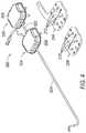
FIG. 3 . From this concept, further solid mechanic and kinematic modeling is used via algorithms in the control computer to convert a desired catheter position or orientation as provided by the user into commands to the instrument driver to rotate motors designated for each pull-wire. - When a catheter is prepared for use with an instrument, its splayer is mounted onto its appropriate interface plate. In this case, as shown in
FIG. 4 ,sheath splayer 308 is placed ontosheath interface plate 206 and aguide splayer 306 is placed ontoguide interface plate 204. In the illustrated example, eachinterface plate openings corresponding drive shafts 314, 316 (FIG. 5 illustrates an underside perspective view ofshafts 314, 316) attached to and extending from the pulley assemblies of thesplayers 308, 306).Drive shafts instrument driver 108. - Embodiments with less or more than four pull-wires are contemplated by the present disclosure. When, e.g., a four-
wire catheter 304 is coupled toinstrument driver 108, eachdrive shaft 316 thereof is thereby coupled to a respective wire 504-510 (seeFIG. 6 ). As such, adistal end 512 ofcatheter 304 can be articulated and steered by selectively tightening and loosening pull-wires 504-510. Typically, the amount of loosening and tightening is slight, relative to the overall length ofcatheter 304. That is, each wire 504-510 typically need not be tightened or loosened more than perhaps a few centimeters. As such, the motors that tighten/loosen each wire typically do not rotate more than, for example, ¾ of a rotation. Thus, given the solid mechanics and kinematics of directing the instrument driver, a catheter (or other shapeable instrument) may be controlled in an open-loop manner, in which the shape configuration command comes in to the beam mechanics and is translated to beam moments and forces, then translated into pull-wire tensions as an intermediate value before finally translated into pull-wire displacement given the entire deformed geometry. Based on the pull-wire displacement command, a motor servo can apply the appropriate electrical current to produce the amount of rotation required to displace the pull-wire. - Robotic systems use algorithms to determine the displacement of the pull-wires to achieve the desired articulation of a catheter. However, differences between predicted and actual catheter position can result from the reliance by the kinematic model on certain assumptions and the lack of certain information. With rigid kinematics, simple geometry can be used to predict the location of any point along the rigid object given the following information: (1) a reference coordinate system; (2) an origin, or point in any coordinate system attached to the object; and (3) an orientation in any coordinate system attached to the object. Even with rigid structures, external forces, even gravity, may disrupt the ability to solve the location equation given the information above. If the above information is not sufficient to accurately describe the position of one point of an object from another point on the same object, then additional information must be provided, like the weight of the object, the forces acting on the object, the strength of the object, etc.
- Standard equations and constants, like Poisons ratio, Hertzian stresses, Modulus of Elasticity, and linear stress/strain equations can improve on the kinematic model but these methods break down once the strains exceed the standard elastic range (usually about 3%). For example, a slim bar may be straight under no distal loading and the equations to predict the location of the distal end are fairly effective. However, when a load is placed on the beam, the distal end will deflect, or strain under the load. Even in a purely elastic response to the load, the location or orientation of the distal end of the beam is impossible to predict without knowing the magnitude, the direction, and the location of the external load. Similarly, flexible instruments such as catheters with low strength can be deflected by unknown loads at unknown locations and in unknown directions. Yet, prediction of the location and orientation of the distal end of a catheter is an important aspect of a robotic catheter system. The orientation of the distal end of the catheter based on information measured at the proximal end can better be determined through embodiments of the present disclosure.
- To enhance the transfer function between inputs and outputs, an embodiment of the present disclosure determines the output motor torque(s) corresponding to the desired tension in the pull-wires and the
instrument driver 108 acts on the output motor torque command to articulate the catheter. A kinematic model for catheter articulation can translate positional data from theinput device 120 at theworkstation 112 into pull-wire displacement commands whereby the motor(s) of theinstrument driver 108 are rotated in accord with that amount of displacement. In contrast, in an exemplary embodiment of the present disclosure, the positional data frominput device 120 is translated into pull-wire tension values tied to motor torque, whereby the motors are rotated in accord with the value of the motor torque. - From a user standpoint, the system behaves much the same way in that the user provides desired catheter motions and the catheter follows. The difference is that by using desired pull-wire tension instead of desired pull-wire displacement, a number of advantages can be achieved. One advantage is the reduction in the number of assumptions in the kinematic model to increase accuracy. For example, with pull-wire displacement calculations, various non-rigid elements affect the amount of articulation for a given pull-wire actuation, including (1) pull-wire stiffness; (2) axial catheter stiffness and (3) actual catheter geometry, including the resultant stiffness of the bending or twisted section. The displacement of the pull-wire at the actuated or proximal end of the catheter is thus not equal to the displacement at the tip of the catheter, but rather a function of the various spring rates. For instance, a small pull-wire will stretch more per unit force and transmit less displacement to the distal tip than a stiffer one though both will transmit the same force.
- Catheter movement may be predicted by modeling the catheter assembly as a system of springs. For example, if the following parameters are known:
- KS: Spring rate of catheter shaft (N/mm)
- KT: Torsional Spring rate of bending section (mm∗N/radian)
- KW: Spring rate of pull-wires (N/mm)
- Further, KT is directly proportional to the Bending Stiffness (N∗mm^2), where KT∗ L = KB where L = Length of bending section. Then the entire catheter can be modeled as a spring system, as shown in
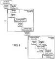
FIG. 7 . The use of pull-wire tension as the output parameter eliminates the need to make such assumptions. That is, the displacement at the tip can be calculated by solving the force equations instead of solving the displacement equation. The transfer function from input to output can thus be improved by commanding theinstrument driver 108 with torque commands correlated to the desired output tensions for the one or more pull-wires in the catheter. - Further, in an exemplary variation of that embodiment of the present disclosure, the high-level catheter control algorithm can be combined with a lower level motor torque control algorithm to accurately drive a catheter in response to a user's commands. Control algorithms may be split into several parts. One aspect of catheter control, as shown in
FIG. 8 and9 in block A, may be a high-level open-loop algorithm combining catheter solid mechanics and kinematics to convert a desired catheter position or orientation as provided by the user into motor commands. Another aspect of catheter control, shown inFIG. 8 and9 in block B, may be a lower-level closed-loop motor servo controller that takes the motor commands produced by the catheter control algorithms and converts them to the motor current needed at every time step to achieve the desired catheter motion.Figure 9 is an exemplary embodiment of the present disclosure illustrating the flow diagram for catheter steering using desired motor torque as the output to the instrument driver. Though a surgical system may control the catheter through the use of motor commands to the motor servos in the form of position commands, increased driving performance can be achieved by altering the architecture such that the motor command transferred to the motor servo controller is a desired motor torque. - Desired motor torques can be determined based on catheter solid mechanics and kinematics control algorithms. For example, the value of the desired tension of the catheter pull-wires can be used to determine the desired motor position. The desired pull-wire tension can be translated to a desired motor torque by multiplying the pull-wire tension by the radius of the pulleys in the splayers.

- Once the desired motor torque is determined, the
instrument driver 108 can apply the desired torques to the motors which in turn applies the desired tension to the pull-wires. - A model-based force control algorithm is an exemplary variation of an embodiment, having the advantages of extreme robustness and stable interaction with the possible passive environments seen at the output shaft of the motor. In the case of the articulation axes, each articulation motor may be treated as a single degree of freedom torque source, in which case for this embodiment, the model-based force control algorithm collapses into an integral controller on force error combined with direct feed-forward of the desired force and a viscous damping term.
Figure 10 is a control block diagram modeling aspects of the flow diagram ofFigure 9 using model-based force control. Since the motor velocity and output torque are a function of both motor dynamics as well as the load produced by the pull-wire, the motor is not modeled as a simple transfer function given the inherently non-linear and time dependent pull-wire dynamics that are constantly changing depending on what the catheter is touching, what shape the catheter has, and how the catheter is being driven. Instead, the combined motor/catheter pull-wire system is modeled as a motor block which takes as an input the net torques applied to the motor (τelec-τwire) where τelec is the electrical torque provided by the amplifiers and calculated by the control algorithm and τwire is the reaction torque provided by the pull-wire. These torques combine with the motor dynamics to produce a motor velocitydO/dt which is then fed into the pull-wire dynamics to produce the torque applied to the pull-wire.- The benefits of the model-based force control algorithm arise in part from its stability for any passive pull-wire load dynamics regardless of non-linearity or complicated geometry. In this variation of one embodiment of the present disclosure, the model-based control algorithm does not allow the force controller to attempt to reject any of the motor's inertial forces as a disturbance in order to achieve a high level of stability. That is, the force control algorithm does not attempt to make the motor feel like it has less mass than it actually has. For this algorithm, the ratioKD/K1 must be greater than the inertia of the motor. Once implemented, the model-based control algorithm essentially works by rejecting any friction in the motor (or gearing) such that the resulting closed-loop system feels like an ideal frictionless motor with inertiaKD/K1. At steady-state and with no acceleration, the integral term in the controller ensures complete friction rejection such that τwire= τdes. At all other times, the difference between τwire and τdes is mostly the inertial force of the motor.

- The above approximation becomes more exact as control termsKD andK1 become larger. Nevertheless, like any control algorithm, limitations exist on the size of the control gains without exciting other unmodeled dynamics in the system and driving the system to instability. The model-based force control strategy provides increased performance while still meeting robustness requirements and without reducing safety.
- The model-based force control strategy is one exemplary implementation of the present disclosure. The torque-based strategy of the pull-wire tension control paradigm can be implemented with numerous possible force control algorithms could be used to get the motors to behave as desired. Further, multiple modifications can be added to the catheter control kinematics and solid mechanics to fine tune catheter driving performance. Exemplary modifications to the motor torque control servo algorithm include: (1) using additional control strategies to modify τdes before sending to the motor servo controller; such as, adding additional damping for enhanced stability or simply for achieving more desirable dynamics; and (2) replacing the integral controller with a high gain, low pass filter to avoid problems (such as integral drift) that typically arise when using integral controllers.
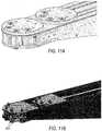
- In order to sense the tension in the catheter control wires, a torque measuring device can be utilized. One exemplary embodiment of the present disclosure, shown in
FIG. 11A and 11B , incorporates torque sensors installed on thedrive shafts - In one embodiment, the tension in the pull-wire can be calculated simply by dividing the torque by the effective radius (rdrum +r wire) of the catheter control wire. Any difference between the actual and commanded motor torque value (an "error signal") can be used to make electrical current adjustments by a motor servo or the control computer to reduce or eliminate the error. Thus, knowledge of the tension (or force) being applied to the pull-wires permits close loop controlled of the catheter movement. Further, with the tension information available, control algorithms can improve the performance and control of the catheter. In some instances, the tension information can provide information about forces being applied to the catheter and can be fed back to the user haptically.
- Indeed, using tension as a predictor of catheter angulations has numerous advantages beyond those discussed above. For example, when the shape of the catheter shaft is unknown as a result of anatomical constraints when inserted into vasculature, un-modeled shaft dynamics may result in unintended articulation.
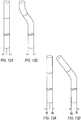
FIG. 12A shows a catheter with a straight shaft and control wires in positions x1 and y1;FIG. 12B shows the same catheter with the shaft bent - with the tip of the catheter bending to the right when the shaft bends to the right. Even though the pull-wires wires are held in their original positions for both conditions, namely x1 and y1, the tip of the catheter is bent to a new position. Because the shaft is no longer straight, the distal tip of the catheter is forced to bend in order to keep the total length between the proximal points x1 and y1 and the distal points x2 and y2 identical. - The use of a desired motor torque as the output instead of a desired motor position improves this issue. Turning to
FIG. 13A and 13B , the initial conditions are shown to be the same but the pull-wires are held under a constant tension. Viewing the kinematic model as weights hung from each wire,FIG. 13B illustrates the shaft bent in a similar manner asFIG 12B , but the distal section remains straight as the path lengths of the pull wires need not be made identical as the constant tension in the control wires kept the distal section articulated to the same angle. The position of the pull-wire has changed to x3 and y3 to accommodate the bend in the shaft. - The present disclosure can also enable distal disturbance detection, i.e., when the distal tip of the catheter has been subjected to an unknown force in an unknown direction, often from tissue contact. Without the distal disturbance, a repeatable relationship exists between catheter pull-wire tension and position, but the disturbance changes the displacement and/or orientation of the tip. Because a difference between commanded and actual positions of the catheter will exist as a result of the disturbance, the length of the path of the control wires will be different than expected. These changes cause a difference in the tension of the wires, provided they are moved away from the commanded location. For instance, if the catheter is commanded to articulate to 180° but a distal disturbance prevents the catheter from bending past 90°, then the tension in the inner wires will be higher than expected and the tension in the outer fibers will be lower due to the difference in path lengths.
FIG. 14 and 15 illustrate a distal disturbance. The amount of pull-wire motion can be correlated to motion expected at the distal section by using a spring model. Using motor torque to steer a catheter, the change in spring rate caused by a disturbance at the distal end of the catheter can be observed. When a disturbance at distal end prevents the catheter tip from achieving the commanded angulation, that resistance of motion at the distal section will effectively change the spring rate of the catheter shaft and the equations will fail to predict the motion. In this example, the angulation is commanded by moving the control wire from position x1 to x2. As governed by the equation, this change in spring rate can be determined via knowledge of the tension in the control wires. Thus, tension or motor torque data can be used to determine adjustments to the motor commands to achieve the desired tension and adjusting motor commands based on real time tension data. This information can also be fed back into the controls software and can be presented to the user as haptic, visual or other feedback to relay the effect of the disturbance.- The distal disturbance shown in
Fig 15 is caused by the catheter coming in contact with an external surface. An alternative distal disturbance may occur when a therapeutic device such as a stent, an atherectomy device or a balloon is being advanced through the catheter. The stiffness of this device cannot be previously modeled because the doctor can choose from a large variety and size range of devices. But a system with tension control can be used to ensure the angle of the tip of the catheter does not change. The increased spring rate of the catheter as the therapeutic device is being advanced can be detected by the tension sensors. Then, this tension or motor torque data can be used to determine adjustments to the motor commands to maintain the catheter tip position. This information can also be fed back into the controls software and can be presented to the user as haptic, visual or other feedback to relay the effect of the increased stiffness. - Embodiments of the present disclosure also have the advantage of enabling compensation for time dependent variables in like plastic creep, which changes the operational working length of the catheter but not the wires, causing tension to reduce over time. Creep compensation can also be compensated for if the tension in the control wires is known. Catheters are generally made from plastic laminates; plastics are known to change dimensions when subjected to external forces over time. This change over time is known as creep. However, with the present disclosure, if the tension in all the wires is less than expected, a catheter shaft length can be compensated for by returning the tensions to their expected values.
- Further, good control of a catheter can be obtained only if the motion expected to be transmitted to the controls wires are indeed transmitted. For a variety of reasons, motion intended to be transmitted to the articulating section may fail. Friction in the gearing or other mechanical aspects of the instrument driver may be problematic. Backlash in the drive transmission can be seen as slack or non-taut pull-wires. The control of the catheter can be improved if the scenario is detected and compensated for adequately, as shown in the flow chart of
FIG. 16 , through general re-zeroing of the pull-wire tension. The process ofFIG. 16 may also be used to accommodate shaft shape compensation when the shaft has been subjected to new unknown forces. The tension on the control wires will be equal and near or equal to zero when the catheter articulating section is straight. However, if the shaft of the catheter bas been deflected, and the catheter has been commanded to be straight, the tension in the catheter control wires will be non-equal. Thus, the equalization and reduction of tension to or near zero is contemplated by the present disclosure. Using tension sensing to take up wire slack may also be performed when the path length for an inside wire is shorter after a bend in the catheter, such as when the catheter is going contralateral over the iliac bifurcation. Further, another use of tension sensing to take up wire slack may occur for a catheter that has spiraled. Steerable catheters often spiral when pushed through the anatomy, resulting in a shorter path for one wire. - A pull-wire tension control paradigm can also inherently implement a safety check to ensure safe and reliable behavior. Exemplary variations of the present disclosure may include enabling tension limits on the control wires to prevent breakage, preventing articulation of the catheter when tension sensing indicates a distal disturbance from potential tissue contact (as discussed further above) and/or limiting the combined loading on the catheter shaft to prevent buckling. Specifically, the direct measurement of torque can signal if the tension in the pull-wire is approaching maximum limits. The catheter controls wires are made of steel and inherently have a breaking strength. One failure mode of catheters is when the pull wires break. This can be prevented by monitoring the tension in the cables and preventing them from being overstressed.
- Further, the tension sensors can be monitored by comparing the motor current at any given moment with the tension measurements. Since the current is related to the torque applied by the motors, a discontinuity between the sensor readings and the current could indicate a potentially faulty tension sensor. Similarly, the present disclosure assists in shaft buckling prevention. The tensile loads in the catheter control wires are reacted by a compressive load in the catheter shaft. Like the wires in tension, the shaft has a loading limit in compression. This limit can be avoided by summing the tension in all the control wires and checking to see that they do not exceed the compressive strength of the shaft.
- Another exemplary aspect of the present disclosure is that non-idealities such as signal saturation may be addressed. For example, an anti-windup algorithm may be included on the integral control term such that the commanded electrical torque, τelec, will never actually exceed what the electronics are capable of producing. Similarly, all control terms are presaturated before adding them together to calculate τelec such that any one term cannot over-power the others when acting at the maximum of the available range.
- Further, if a fault condition was detected when driving in tension control mode relating to the tension sensor or another aspect of the tension control mode, the system could be shut down the system or, in the alternative, an automatic switch to position control could be implemented. The tension control mode has the advantage of compatibility with the position control mode, enabling the two modes to back up the other. The catheter kinematics and solid mechanics for the modes enable smooth transition from tension control mode into position control mode. This would allow us to keep the doctor in control of the catheter in the case of a fault that only affects the tension sensing system without abruptly ending the procedure. Naturally, some care would have to be taken to avoid the potential for unintentional motion as the algorithms transition.
- Another embodiment of the present disclosure would include the ability of a surgeon or other user to switch between the torque-based paradigm and the position-based paradigm, with one or the other serving as a default mode. For example, the position-based paradigm could be utilized as the default mode with the ability for a surgeon to switch to the torque-based mode for certain procedures. The control computer could automatically switch between the modes based on parameters that are input into the system or feedback during the procedure. Alternatively, the instrument driver may incorporate the desired motor torque value in a closed loop system. A variation of the present disclosure contemplates using both the position-based and torque-based paradigms during a surgical procedure, where, e.g., the system implements catheter articulation in the first instance through motor displacement commands but the associated desired motor torque is used to ensure that the desired deflection angle is achieved and/or maintained. Further, in another embodiment of the present disclosure, other modes of operation could be enabled, such as the ability of a constant force mode, in which the articulation force is maintained, creating a force against the tissue that is more uniform while crossing trabeculated tissue.
- Another aspect of the current disclosure is to use the torque sensing capability on the pull-wires to pull all wires at the same time and stiffen the catheter. For typical articulation of a catheter as shown in
FIG. 12A , one wire is pulled by a distance x1 and the opposing wire is typically released by a distance y1. This delta wire displacement causes the tip of the catheter to deflect as described above. However, if both wires are pulled equal amounts, then the tip will not deflect. Instead, the tensioned wires inside the wall of the catheter serve to stiffen the catheter. One of catheter design challenge is that there are times when a catheter needs to be stiff to provide stability for delivering therapeutic devices through it and there are times when it needs to be flexible to navigate through tortuous vessels. Many conventional catheters attempt to overcome this issue by designing catheters with variable stiffness - that is to say the distal end is manufactured with less stiff materials than the proximal end. Tension sensing on the catheter pull wires allows dynamic variable stiffness. In other words, the catheter can be manufactured with less stiff materials and the doctor has the ability to increase tension on all wires and stiffen the catheter when required. It should be understood that this dynamic variable stiffness can be applied in any catheter configuration and with any given catheter tip articulation. For example, if one pull-wire is pulled by 1N more than another, then the catheter tip may be deflected 30°. The dynamic variable stiffness algorithm would now apply an additional 2N to each of the 2 wires to increase the stiffness. The delta between the two wires is still 1N so the tip does not change angle. Operator workstation 112 may include a computer or a computer readable storage medium implementing the operation ofinstrument driver 108. In general, computing systems and/or devices, such as the processor and the user input device, may employ any of a number of computer operating systems, including, but by no means limited to, versions and/or varieties of the Microsoft Windows® operating system, the Unix operating system (e.g., the Solaris® operating system distributed by Oracle Corporation of Redwood Shores, California), the AIX UNIX operating system distributed by International Business Machines of Armonk, New York, the Linux operating system, the Mac OS X and iOS operating systems distributed by Apple Inc. of Cupertino, California, and the Android operating system developed by the Open Handset Alliance.- Computing devices generally include computer-executable instructions, where the instructions may be executable by one or more computing devices such as those listed above. Computer-executable instructions may be compiled or interpreted from computer programs created using a variety of programming languages and/or technologies, including, without limitation, and either alone or in combination, Java™, C, C++, Visual Basic, Java Script, Perl, etc. In general, a processor (e.g., a microprocessor) receives instructions, e.g., from a memory, a computer-readable medium, etc., and executes these instructions, thereby performing one or more processes, including one or more of the processes described herein. Such instructions and other data may be stored and transmitted using a variety of computer-readable media.
- A computer-readable medium (also referred to as a processor-readable medium) includes any non-transitory (e.g., tangible) medium that participates in providing data (e.g., instructions) that may be read by a computer (e.g., by a processor of a computer). Such a medium may take many forms, including, but not limited to, non-volatile media and volatile media. Non-volatile media may include, for example, optical or magnetic disks and other persistent memory. Volatile media may include, for example, dynamic random access memory (DRAM), which typically constitutes a main memory. Such instructions may be transmitted by one or more transmission media, including coaxial cables, copper wire and fiber optics, including the wires that comprise a system bus coupled to a processor of a computer. Common forms of computer-readable media include, for example, a floppy disk, a flexible disk, hard disk, magnetic tape, any other magnetic medium, a CD-ROM, DVD, any other optical medium, punch cards, paper tape, any other physical medium with patterns of holes, a RAM, a PROM, an EPROM, a FLASH-EEPROM, any other memory chip or cartridge, or any other medium from which a computer can read.
- Databases, data repositories or other data stores described herein may include various kinds of mechanisms for storing, accessing, and retrieving various kinds of data, including a hierarchical database, a set of files in a file system, an application database in a proprietary format, a relational database management system (RDBMS), etc. Each such data store is generally included within a computing device employing a computer operating system such as one of those mentioned above, and are accessed via a network in any one or more of a variety of manners. A file system may be accessible from a computer operating system, and may include files stored in various formats. An RDBMS generally employs the Structured Query Language (SQL) in addition to a language for creating, storing, editing, and executing stored procedures, such as the PL/SQL language mentioned above.
- In some examples, system elements may be implemented as computer-readable instructions (e.g., software) on one or more computing devices (e.g., servers, personal computers, etc.), stored on computer readable media associated therewith (e.g., disks, memories, etc.). A computer program product may comprise such instructions stored on computer readable media for carrying out the functions described herein.


Claims (12)
- A robotic surgical system (100), comprising an input device (120), a motor torque sensor, a control system operatively connected to the input device (120), and an instrument driver (108) operatively connected to the control system to insert a catheter (106, 304) within an anatomical lumen of a patient, the catheter (106, 304) comprising a flexible shaft, an articulating distal tip (512), and an actuating pull-wire (504-510) attached to the articulating distal tip (512) and extending a length of the catheter (106, 304), wherein:the input device (120) is configured to receive a commanded deflection of the distal articulating tip (512) and output a desired position of the distal articulating tip (512);the control system is configured to translate the desired position into an output motor torque; anda motor of the instrument driver (108) is configured to apply the output motor torque from the control system to adjust a tension in the pull-wire (504-510) such that the articulating distal tip (512) reaches the commanded deflection independent of forces acting on the flexible shaft by using actual motor torque feedback from the torque sensor to determine an adjustment to the output motor torque.
- The system of claim 1, wherein the control system further comprises an algorithm including at least one set of instructions that defines a catheter movement profile using motor torque as an output to the instrument driver.
- The system of any one of the preceding claims, wherein the system further comprises a motor servo configured to receive torque data from the torque measuring sensor and to determine adjustments to the electrical current supplied to the motor to achieve the output motor torque.
- The system of any one of the preceding claims, wherein the motor is rotated using closed loop feedback to sense any difference between actual motor torque and the output motor torque so as to adapt the electrical current to correct for any difference with the output motor torque.
- The system of any one of the preceding claims, wherein the control system uses actual motor torque feedback to adapt kinematic parameters to determine the adjustment to the output motor torque.
- The system of any one of the preceding claims, wherein the instrument driver is configured to rotate at least one motor in accord with both the output motor torque from the control system and an output motor angular displacement calculated by the control system.
- The system of any one of the preceding claims, wherein the instrument driver is configured to adjust pull-wire tension to ensure the distal tip of the catheter reaches a commanded deflection angle.
- The system of any one of the preceding claims, wherein the instrument driver is configured to adjust pull-wire tension to ensure the distal tip of the catheter stays at a commanded deflection angle.
- The system of any one of the preceding claims, wherein the instrument driver can be controlled to increase tension on all pull-wires to stiffen the catheter and thereby provide dynamic variable catheter stiffness.
- The system of any one of the preceding claims, wherein the instrument driver is configured to adjust pull-wire tension to ensure the distal tip of the catheter is articulated at a constant force.
- The system of any one of the preceding claims, wherein the instrument driver is configured to limit the maximum tension applied to pull-wires.
- The system of any one of the preceding claims, wherein the instrument driver is configured to provide haptic feedback to a user as a measure of the tension applied to the pull-wires.
Applications Claiming Priority (1)
| Application Number | Priority Date | Filing Date | Title |
|---|---|---|---|
| US13/828,342US9173713B2 (en) | 2013-03-14 | 2013-03-14 | Torque-based catheter articulation |
Publications (3)
| Publication Number | Publication Date |
|---|---|
| EP2786721A2 EP2786721A2 (en) | 2014-10-08 |
| EP2786721A3 EP2786721A3 (en) | 2015-03-11 |
| EP2786721B1true EP2786721B1 (en) | 2020-05-13 |
Family
ID=50336107
Family Applications (1)
| Application Number | Title | Priority Date | Filing Date |
|---|---|---|---|
| EP14160090.8AActiveEP2786721B1 (en) | 2013-03-14 | 2014-03-14 | Torque-based catheter articulation |
Country Status (2)
| Country | Link |
|---|---|
| US (5) | US9173713B2 (en) |
| EP (1) | EP2786721B1 (en) |
Families Citing this family (143)
| Publication number | Priority date | Publication date | Assignee | Title |
|---|---|---|---|---|
| US8414505B1 (en) | 2001-02-15 | 2013-04-09 | Hansen Medical, Inc. | Catheter driver system |
| WO2005087128A1 (en) | 2004-03-05 | 2005-09-22 | Hansen Medical, Inc. | Robotic catheter system |
| JP2009500086A (en) | 2005-07-01 | 2009-01-08 | ハンセン メディカル,インク. | Robotic guide catheter system |
| US12290277B2 (en) | 2007-01-02 | 2025-05-06 | Aquabeam, Llc | Tissue resection with pressure sensing |
| US9232959B2 (en) | 2007-01-02 | 2016-01-12 | Aquabeam, Llc | Multi fluid tissue resection methods and devices |
| ES2769535T3 (en) | 2008-03-06 | 2020-06-26 | Aquabeam Llc | Tissue ablation and cauterization with optical energy carried in a fluid stream |
| US20100114081A1 (en) | 2008-11-05 | 2010-05-06 | Spectranetics | Biasing laser catheter: monorail design |
| US8702773B2 (en) | 2008-12-17 | 2014-04-22 | The Spectranetics Corporation | Eccentric balloon laser catheter |
| US9254123B2 (en) | 2009-04-29 | 2016-02-09 | Hansen Medical, Inc. | Flexible and steerable elongate instruments with shape control and support elements |
| US8672837B2 (en) | 2010-06-24 | 2014-03-18 | Hansen Medical, Inc. | Methods and devices for controlling a shapeable medical device |
| US20120071752A1 (en) | 2010-09-17 | 2012-03-22 | Sewell Christopher M | User interface and method for operating a robotic medical system |
| US20130030363A1 (en) | 2011-07-29 | 2013-01-31 | Hansen Medical, Inc. | Systems and methods utilizing shape sensing fibers |
| EP3351196A1 (en) | 2012-02-29 | 2018-07-25 | Procept Biorobotics Corporation | Automated image-guided tissue resection and treatment |
| EP3738638A1 (en) | 2012-03-15 | 2020-11-18 | Fisher & Paykel Healthcare Limited | Respiratory gas humidification system |
| US10383765B2 (en) | 2012-04-24 | 2019-08-20 | Auris Health, Inc. | Apparatus and method for a global coordinate system for use in robotic surgery |
| GB2575894A (en) | 2012-04-27 | 2020-01-29 | Fisher & Paykel Healthcare Ltd | Usability features for respiratory humidification system |
| US20130317519A1 (en) | 2012-05-25 | 2013-11-28 | Hansen Medical, Inc. | Low friction instrument driver interface for robotic systems |
| US20140148673A1 (en) | 2012-11-28 | 2014-05-29 | Hansen Medical, Inc. | Method of anchoring pullwire directly articulatable region in catheter |
| US10231867B2 (en) | 2013-01-18 | 2019-03-19 | Auris Health, Inc. | Method, apparatus and system for a water jet |
| US9668814B2 (en) | 2013-03-07 | 2017-06-06 | Hansen Medical, Inc. | Infinitely rotatable tool with finite rotating drive shafts |
| US9057600B2 (en) | 2013-03-13 | 2015-06-16 | Hansen Medical, Inc. | Reducing incremental measurement sensor error |
| US20140277334A1 (en) | 2013-03-14 | 2014-09-18 | Hansen Medical, Inc. | Active drives for robotic catheter manipulators |
| US9326822B2 (en) | 2013-03-14 | 2016-05-03 | Hansen Medical, Inc. | Active drives for robotic catheter manipulators |
| US9173713B2 (en) | 2013-03-14 | 2015-11-03 | Hansen Medical, Inc. | Torque-based catheter articulation |
| US11213363B2 (en) | 2013-03-14 | 2022-01-04 | Auris Health, Inc. | Catheter tension sensing |
| US9498601B2 (en) | 2013-03-14 | 2016-11-22 | Hansen Medical, Inc. | Catheter tension sensing |
| US9014851B2 (en) | 2013-03-15 | 2015-04-21 | Hansen Medical, Inc. | Systems and methods for tracking robotically controlled medical instruments |
| US20140276647A1 (en) | 2013-03-15 | 2014-09-18 | Hansen Medical, Inc. | Vascular remote catheter manipulator |
| US20140276936A1 (en) | 2013-03-15 | 2014-09-18 | Hansen Medical, Inc. | Active drive mechanism for simultaneous rotation and translation |
| US9452018B2 (en) | 2013-03-15 | 2016-09-27 | Hansen Medical, Inc. | Rotational support for an elongate member |
| US9408669B2 (en) | 2013-03-15 | 2016-08-09 | Hansen Medical, Inc. | Active drive mechanism with finite range of motion |
| US9271663B2 (en) | 2013-03-15 | 2016-03-01 | Hansen Medical, Inc. | Flexible instrument localization from both remote and elongation sensors |
| US9629595B2 (en) | 2013-03-15 | 2017-04-25 | Hansen Medical, Inc. | Systems and methods for localizing, tracking and/or controlling medical instruments |
| US11020016B2 (en) | 2013-05-30 | 2021-06-01 | Auris Health, Inc. | System and method for displaying anatomy and devices on a movable display |
| WO2014201165A1 (en) | 2013-06-11 | 2014-12-18 | Auris Surgical Robotics, Inc. | System for robotic assisted cataract surgery |
| JP6663850B2 (en) | 2013-09-13 | 2020-03-13 | フィッシャー アンド ペイケル ヘルスケア リミテッド | Humidification system connection |
| EP3060157B1 (en) | 2013-10-24 | 2019-12-11 | Auris Health, Inc. | System for robotic-assisted endolumenal surgery |
| US10449319B2 (en) | 2014-02-07 | 2019-10-22 | Fisher & Paykel Healthcare Limited | Respiratory humidification system |
| EP3243476B1 (en) | 2014-03-24 | 2019-11-06 | Auris Health, Inc. | Systems and devices for catheter driving instinctiveness |
| US10046140B2 (en) | 2014-04-21 | 2018-08-14 | Hansen Medical, Inc. | Devices, systems, and methods for controlling active drive systems |
| US10569052B2 (en) | 2014-05-15 | 2020-02-25 | Auris Health, Inc. | Anti-buckling mechanisms for catheters |
| CN106535971B (en) | 2014-06-03 | 2020-12-04 | 费雪派克医疗保健有限公司 | Flow mixers for respiratory therapy systems |
| US9561083B2 (en) | 2014-07-01 | 2017-02-07 | Auris Surgical Robotics, Inc. | Articulating flexible endoscopic tool with roll capabilities |
| US9744335B2 (en) | 2014-07-01 | 2017-08-29 | Auris Surgical Robotics, Inc. | Apparatuses and methods for monitoring tendons of steerable catheters |
| US10792464B2 (en) | 2014-07-01 | 2020-10-06 | Auris Health, Inc. | Tool and method for using surgical endoscope with spiral lumens |
| EP3200718A4 (en) | 2014-09-30 | 2018-04-25 | Auris Surgical Robotics, Inc | Configurable robotic surgical system with virtual rail and flexible endoscope |
| US10314463B2 (en) | 2014-10-24 | 2019-06-11 | Auris Health, Inc. | Automated endoscope calibration |
| WO2016069754A1 (en) | 2014-10-29 | 2016-05-06 | The Spectranetics Corporation | Laser energy delivery devices including laser transmission detection systems and methods |
| US10492863B2 (en) | 2014-10-29 | 2019-12-03 | The Spectranetics Corporation | Laser energy delivery devices including laser transmission detection systems and methods |
| CN107835704B (en) | 2015-03-27 | 2020-12-15 | 项目莫里股份有限公司 | Fluid drive system for catheter articulation and other uses |
| GB2538497B (en) | 2015-05-14 | 2020-10-28 | Cmr Surgical Ltd | Torque sensing in a surgical robotic wrist |
| US10820908B2 (en) | 2015-08-19 | 2020-11-03 | Hays, Inc. | Adjustable flow narrow profile balloon for use with a catheter and methods of use |
| US10154847B2 (en)* | 2015-08-19 | 2018-12-18 | Hays, Inc. | Narrow profile balloon for use with an occlusion device, methods of use, and uses thereof |
| CN108348133B (en) | 2015-09-09 | 2020-11-13 | 奥瑞斯健康公司 | Instrument Manipulators for Surgical Robotic Systems |
| US9955986B2 (en) | 2015-10-30 | 2018-05-01 | Auris Surgical Robotics, Inc. | Basket apparatus |
| US10231793B2 (en) | 2015-10-30 | 2019-03-19 | Auris Health, Inc. | Object removal through a percutaneous suction tube |
| US9949749B2 (en) | 2015-10-30 | 2018-04-24 | Auris Surgical Robotics, Inc. | Object capture with a basket |
| US10143526B2 (en) | 2015-11-30 | 2018-12-04 | Auris Health, Inc. | Robot-assisted driving systems and methods |
| WO2017096362A1 (en) | 2015-12-04 | 2017-06-08 | Barrish Mark D | Lateral articulation anchors for catheters and other uses |
| CN108601925B (en) | 2015-12-04 | 2021-06-29 | 项目莫里股份有限公司 | Input and articulation system for catheters and other uses |
| US11376087B2 (en) | 2016-01-12 | 2022-07-05 | Intuitive Surgical Operations, Inc. | Uniform scaling of haptic actuators |
| US11833034B2 (en) | 2016-01-13 | 2023-12-05 | Shifamed Holdings, Llc | Prosthetic cardiac valve devices, systems, and methods |
| KR102708262B1 (en) | 2016-02-05 | 2024-09-20 | 보드 오브 리전츠, 더 유니버시티 오브 텍사스 시스템 | The manipulatable intraruminal medical device |
| BR112018009251A2 (en) | 2016-02-05 | 2019-04-09 | Board Of Regents Of The University Of Texas System | surgical apparatus and customized main controller for a surgical apparatus |
| WO2017143170A1 (en) | 2016-02-17 | 2017-08-24 | Keith Phillip Laby | Local contraction of flexible bodies using balloon expansion for extension-contraction catheter articulation and other uses |
| CN105616008B (en)* | 2016-03-16 | 2018-06-08 | 北京理工大学 | Conduit-seal wire cooperating intervenes surgical assistant system from side controller |
| US11420021B2 (en) | 2016-03-25 | 2022-08-23 | Project Moray, Inc. | Fluid-actuated displacement for catheters, continuum manipulators, and other uses |
| EP3432834B1 (en) | 2016-03-25 | 2021-01-13 | Project Moray, Inc. | Fluid-actuated sheath displacement and articulation behavior improving systems for catheters |
| US10454347B2 (en) | 2016-04-29 | 2019-10-22 | Auris Health, Inc. | Compact height torque sensing articulation axis assembly |
| US10463439B2 (en) | 2016-08-26 | 2019-11-05 | Auris Health, Inc. | Steerable catheter with shaft load distributions |
| US11241559B2 (en) | 2016-08-29 | 2022-02-08 | Auris Health, Inc. | Active drive for guidewire manipulation |
| KR20230096148A (en) | 2016-08-31 | 2023-06-29 | 아우리스 헬스, 인코포레이티드 | Length conservative surgical instrument |
| CN106377316B (en)* | 2016-09-18 | 2020-07-14 | 上海交通大学 | Operation equipment for thyroid minimally invasive surgery |
| CN110603005A (en) | 2016-09-28 | 2019-12-20 | 项目莫里股份有限公司 | Delivery methods and devices for arrhythmia diagnosis and/or treatment, and robotic systems for other uses |
| CN109996490B (en) | 2016-09-28 | 2023-01-10 | 项目莫里股份有限公司 | Base station, charging station and/or server for robotic catheter systems and other uses, and improved articulation apparatus and systems |
| US9931025B1 (en)* | 2016-09-30 | 2018-04-03 | Auris Surgical Robotics, Inc. | Automated calibration of endoscopes with pull wires |
| EP3551978B1 (en) | 2016-12-07 | 2022-01-26 | Fisher&Paykel Healthcare Limited | Sensing arrangements for medical devices |
| US10543048B2 (en) | 2016-12-28 | 2020-01-28 | Auris Health, Inc. | Flexible instrument insertion using an adaptive insertion force threshold |
| US10244926B2 (en) | 2016-12-28 | 2019-04-02 | Auris Health, Inc. | Detecting endolumenal buckling of flexible instruments |
| IT201700042116A1 (en) | 2017-04-14 | 2018-10-14 | Medical Microinstruments Spa | ROBOTIC ASSEMBLY FOR SURGERY |
| US10905861B2 (en) | 2017-04-25 | 2021-02-02 | Project Moray, Inc. | Matrix supported balloon articulation systems, devices, and methods for catheters and other uses |
| KR102643758B1 (en) | 2017-05-12 | 2024-03-08 | 아우리스 헬스, 인코포레이티드 | Biopsy devices and systems |
| KR102391591B1 (en)* | 2017-05-16 | 2022-04-27 | 박연호 | Apparatus for estimating shape of flexible portion and endoscope system comprising the same |
| US10299870B2 (en) | 2017-06-28 | 2019-05-28 | Auris Health, Inc. | Instrument insertion compensation |
| US11026758B2 (en) | 2017-06-28 | 2021-06-08 | Auris Health, Inc. | Medical robotics systems implementing axis constraints during actuation of one or more motorized joints |
| US10426559B2 (en)* | 2017-06-30 | 2019-10-01 | Auris Health, Inc. | Systems and methods for medical instrument compression compensation |
| CN107334533B (en)* | 2017-07-31 | 2023-02-28 | 成都博恩思医学机器人有限公司 | Bracket component, surgical instrument of surgical robot and surgical robot |
| US10145747B1 (en) | 2017-10-10 | 2018-12-04 | Auris Health, Inc. | Detection of undesirable forces on a surgical robotic arm |
| EP3700454A1 (en)* | 2017-10-26 | 2020-09-02 | Guido Danieli | Robotic system for angioplasty and endoluminar surgery |
| EP3684282B1 (en) | 2017-12-06 | 2024-02-21 | Auris Health, Inc. | Systems to correct for uncommanded instrument roll |
| JP7208237B2 (en) | 2017-12-08 | 2023-01-18 | オーリス ヘルス インコーポレイテッド | Systems and medical devices for performing medical procedures |
| CN111770736A (en) | 2017-12-11 | 2020-10-13 | 奥瑞斯健康公司 | Systems and methods for instrument-based insertion architectures |
| US11510736B2 (en) | 2017-12-14 | 2022-11-29 | Auris Health, Inc. | System and method for estimating instrument location |
| EP3740150A4 (en) | 2018-01-17 | 2021-11-03 | Auris Health, Inc. | SURGICAL ROBOTIC SYSTEMS WITH IMPROVED ROBOTIC ARMS |
| KR20240118200A (en) | 2018-02-13 | 2024-08-02 | 아우리스 헬스, 인코포레이티드 | System and method for driving medical instrument |
| JP7183062B2 (en) | 2018-03-23 | 2022-12-05 | キヤノン株式会社 | CONTINUOUS ROBOT CONTROL DEVICE, CONTINUOUS ROBOT CONTROL METHOD AND PROGRAM |
| US11071441B2 (en)* | 2018-04-20 | 2021-07-27 | Verb Surgical Inc. | Surgical robotic tool multi-motor actuator and controller |
| CN110623747B (en)* | 2018-06-22 | 2021-07-09 | 深圳市精锋医疗科技有限公司 | Connecting mechanism, power mechanism, operating arm and slave operating equipment |
| KR102712920B1 (en) | 2018-06-27 | 2024-10-07 | 아우리스 헬스, 인코포레이티드 | Alignment and attachment systems for medical devices |
| US11241233B2 (en)* | 2018-07-10 | 2022-02-08 | Covidien Lp | Apparatus for ensuring strain gauge accuracy in medical reusable device |
| AU2019325548B2 (en) | 2018-08-21 | 2025-06-26 | Shifamed Holdings, Llc | Prosthetic cardiac valve devices, systems, and methods |
| CN113164184B (en) | 2018-08-24 | 2024-06-14 | 奥瑞斯健康公司 | Medical instrument capable of being controlled manually and robotically |
| CN112804959B (en) | 2018-09-28 | 2025-01-28 | 奥瑞斯健康公司 | Robotic systems and methods for accompanying endoscopic and percutaneous medical procedures |
| KR102852843B1 (en) | 2018-09-28 | 2025-09-03 | 아우리스 헬스, 인코포레이티드 | System and method for docking medical devices |
| WO2020069080A1 (en) | 2018-09-28 | 2020-04-02 | Auris Health, Inc. | Devices, systems, and methods for manually and robotically driving medical instruments |
| CN113260337A (en) | 2018-10-05 | 2021-08-13 | 施菲姆德控股有限责任公司 | Prosthetic heart valve devices, systems, and methods |
| CN113056302B (en) | 2018-10-19 | 2023-03-28 | 施菲姆德控股有限责任公司 | Adjustable medical device |
| US11998284B2 (en)* | 2018-12-07 | 2024-06-04 | Acclarent, Inc. | Articulating guide with integral position sensor |
| US20200197097A1 (en) | 2018-12-20 | 2020-06-25 | Biosense Webster (Israel) Ltd. | Catheter representation using a dynamic spring model |
| CN113226202B (en) | 2018-12-28 | 2024-12-03 | 奥瑞斯健康公司 | Percutaneous sheath and method for robotic medical system |
| EP3941391B1 (en) | 2019-03-19 | 2024-12-04 | Shifamed Holdings, LLC | Prosthetic cardiac valve devices, systems |
| WO2020197671A1 (en) | 2019-03-22 | 2020-10-01 | Auris Health, Inc. | Systems and methods for aligning inputs on medical instruments |
| WO2021028883A1 (en) | 2019-08-15 | 2021-02-18 | Auris Health, Inc. | Medical device having multiple bending sections |
| US11896330B2 (en) | 2019-08-15 | 2024-02-13 | Auris Health, Inc. | Robotic medical system having multiple medical instruments |
| US11737845B2 (en) | 2019-09-30 | 2023-08-29 | Auris Inc. | Medical instrument with a capstan |
| WO2021137108A1 (en) | 2019-12-31 | 2021-07-08 | Auris Health, Inc. | Alignment interfaces for percutaneous access |
| WO2021137109A1 (en) | 2019-12-31 | 2021-07-08 | Auris Health, Inc. | Alignment techniques for percutaneous access |
| EP4084724A4 (en) | 2019-12-31 | 2023-12-27 | Auris Health, Inc. | ADVANCED BASKET DRIVE MODE |
| EP4084721B1 (en) | 2019-12-31 | 2025-10-01 | Auris Health, Inc. | Anatomical feature identification and targeting |
| CN114901188A (en) | 2019-12-31 | 2022-08-12 | 奥瑞斯健康公司 | Dynamic pulley system |
| US11586275B2 (en)* | 2020-01-09 | 2023-02-21 | Baker Hughes Oilfield Operations Llc | Cable force adjustment |
| CN111388093B (en)* | 2020-02-19 | 2020-12-01 | 哈尔滨工业大学 | A robot based on cooperative joint motor and its control method |
| JP7379208B2 (en)* | 2020-02-21 | 2023-11-14 | キヤノン株式会社 | Continuum robot control system and control method, and continuum robot |
| CN114867429A (en)* | 2020-03-27 | 2022-08-05 | 直观外科手术操作公司 | System and method for controlling an instrument |
| US11737663B2 (en) | 2020-03-30 | 2023-08-29 | Auris Health, Inc. | Target anatomical feature localization |
| EP4167892A4 (en) | 2020-06-19 | 2024-10-30 | Remedy Robotics, Inc. | SYSTEMS AND METHODS FOR GUIDING INTRALUMINAL DEVICES WITHIN THE VASCULAR SYSTEM |
| US20220016394A1 (en)* | 2020-07-16 | 2022-01-20 | Canon U.S.A., Inc. | Medical Apparatus and Method of Use Thereof |
| US11844580B2 (en) | 2020-08-27 | 2023-12-19 | Verb Surgical Inc. | Control of a surgical instrument having backlash, friction, and compliance under external load in a surgical robotic system |
| CN116456937A (en) | 2020-08-31 | 2023-07-18 | 施菲姆德控股有限责任公司 | Prosthetic Valve Delivery System |
| US12329635B2 (en) | 2020-12-04 | 2025-06-17 | Shifamed Holdings, Llc | Flared prosthetic cardiac valve delivery devices and systems |
| US12201521B2 (en) | 2021-03-22 | 2025-01-21 | Shifamed Holdings, Llc | Anchor position verification for prosthetic cardiac valve devices |
| US12121307B2 (en) | 2021-07-01 | 2024-10-22 | Remedy Robotics, Inc. | Vision-based position and orientation determination for endovascular tools |
| EP4364163A1 (en) | 2021-07-01 | 2024-05-08 | Remedy Robotics, Inc. | Vision-based position and orientation determination for endovascular tools |
| US11707332B2 (en) | 2021-07-01 | 2023-07-25 | Remedy Robotics, Inc. | Image space control for endovascular tools |
| CN113491816B (en)* | 2021-07-06 | 2023-06-27 | 上海康德莱医疗器械股份有限公司 | Electric positioning controllable bending guide wire |
| CN114451998B (en)* | 2021-10-11 | 2024-04-19 | 上海微创微航机器人有限公司 | Medical catheter, shape control system and method thereof and surgical robot |
| WO2023069188A1 (en)* | 2021-10-20 | 2023-04-27 | Boston Scientific Scimed, Inc. | Fly by wire control for atherectomy |
| CN114890236B (en)* | 2022-06-09 | 2024-06-18 | 中国人民解放军陆军特色医学中心 | Digital detection device and method for tension of transmission steel wire of surgical robot |
| CN117838314A (en)* | 2022-09-30 | 2024-04-09 | 深圳市精锋医疗科技股份有限公司 | A catheter robot and control method thereof |
| CN115554568A (en)* | 2022-11-28 | 2023-01-03 | 深圳市精锋医疗科技股份有限公司 | Catheter bending steering control method, catheter system and storage medium |
| CN115957008A (en)* | 2022-11-29 | 2023-04-14 | 上海微创微航机器人有限公司 | Catheter control method, system and storage medium |
| WO2024253981A1 (en)* | 2023-06-08 | 2024-12-12 | Covidien Lp | Surgical robotic system and method for cable fatigue estimation of surgical instruments |
| CN117426809B (en)* | 2023-12-21 | 2024-03-15 | 苏州康多机器人有限公司 | Tensioning method and tensioning tool for rope of surgical instrument |
Family Cites Families (373)
| Publication number | Priority date | Publication date | Assignee | Title |
|---|---|---|---|---|
| US2556601A (en) | 1947-02-10 | 1951-06-12 | Niles Bement Pond Co | Multiple tapping head |
| US2566183A (en) | 1947-05-29 | 1951-08-28 | Skilsaw Inc | Portable power-driven tool |
| US2623175A (en) | 1949-03-25 | 1952-12-23 | Radiart Corp | Reel antenna |
| US2730699A (en) | 1952-02-01 | 1956-01-10 | Gen Dynamics Corp | Telemetering system |
| US2884808A (en) | 1957-10-23 | 1959-05-05 | Mueller Co | Drive for drilling machine |
| US3294183A (en) | 1964-09-30 | 1966-12-27 | Black & Decker Mfg Co | Power driven tools |
| US3472083A (en) | 1967-10-25 | 1969-10-14 | Lawrence S Schnepel | Torque wrench |
| US3513724A (en) | 1968-07-17 | 1970-05-26 | Monogram Ind Inc | Speed reduction mechanism |
| US3595074A (en) | 1968-10-30 | 1971-07-27 | Clarence Johnson | Torque transducer |
| JPS5025234B1 (en) | 1970-02-20 | 1975-08-21 | ||
| JPS4921672Y1 (en) | 1970-08-21 | 1974-06-10 | ||
| GB1372327A (en) | 1971-10-11 | 1974-10-30 | Commissariat Energie Atomique | Articulated manipulator |
| US3734207A (en) | 1971-12-27 | 1973-05-22 | M Fishbein | Battery powered orthopedic cutting tool |
| US3926386A (en) | 1974-07-09 | 1975-12-16 | Us Air Force | Spool for wire deployment |
| US3921536A (en) | 1975-01-30 | 1975-11-25 | Hall Ski Lift Company Inc | Cable grip tester |
| DE2524605A1 (en) | 1975-06-03 | 1976-12-23 | Heinz Peter Dipl Brandstetter | DEVICE FOR MEASURING MECHANICAL WORK AND POWER |
| SE414272B (en) | 1978-10-17 | 1980-07-21 | Viggo Ab | CANNEL OR CATETER DEVICE |
| US4241884A (en) | 1979-03-20 | 1980-12-30 | George Lynch | Powered device for controlling the rotation of a reel |
| AT365363B (en) | 1979-09-20 | 1982-01-11 | Philips Nv | RECORDING AND / OR PLAYING DEVICE |
| CH643092A5 (en) | 1980-02-18 | 1984-05-15 | Gruenbaum Heinrich Leuzinger | DEVICE FOR MEASURING TORQUE EXTENDED BY AN ELECTRIC MOTOR. |
| US4357843A (en) | 1980-10-31 | 1982-11-09 | Peck-O-Matic, Inc. | Tong apparatus for threadedly connecting and disconnecting elongated members |
| JPS57144633A (en) | 1981-03-05 | 1982-09-07 | Inoue Japax Res Inc | Wire electrode feeder |
| US4507026A (en) | 1982-09-29 | 1985-03-26 | Boeing Aerospace Company | Depth control assembly |
| US4555960A (en) | 1983-03-23 | 1985-12-03 | Cae Electronics, Ltd. | Six degree of freedom hand controller |
| US4688555A (en) | 1986-04-25 | 1987-08-25 | Circon Corporation | Endoscope with cable compensating mechanism |
| US4784150A (en) | 1986-11-04 | 1988-11-15 | Research Corporation | Surgical retractor and blood flow monitor |
| US4745908A (en) | 1987-05-08 | 1988-05-24 | Circon Corporation | Inspection instrument fexible shaft having deflection compensation means |
| US4907168A (en) | 1988-01-11 | 1990-03-06 | Adolph Coors Company | Torque monitoring apparatus |
| US4857058A (en) | 1988-07-11 | 1989-08-15 | Payton Hugh W | Support patch for intravenous catheter |
| US4945790A (en) | 1989-08-07 | 1990-08-07 | Arthur Golden | Multi-purpose hand tool |
| US5086401A (en) | 1990-05-11 | 1992-02-04 | International Business Machines Corporation | Image-directed robotic system for precise robotic surgery including redundant consistency checking |
| US5350101A (en) | 1990-11-20 | 1994-09-27 | Interventional Technologies Inc. | Device for advancing a rotatable tube |
| US5234428A (en) | 1991-06-11 | 1993-08-10 | Kaufman David I | Disposable electrocautery/cutting instrument with integral continuous smoke evacuation |
| US5417210A (en) | 1992-05-27 | 1995-05-23 | International Business Machines Corporation | System and method for augmentation of endoscopic surgery |
| JPH05146975A (en) | 1991-11-26 | 1993-06-15 | Bridgestone Corp | Multi-shaft automatic nut runner |
| US5256150A (en) | 1991-12-13 | 1993-10-26 | Endovascular Technologies, Inc. | Large-diameter expandable sheath and method |
| US5631973A (en) | 1994-05-05 | 1997-05-20 | Sri International | Method for telemanipulation with telepresence |
| US5207128A (en) | 1992-03-23 | 1993-05-04 | Weatherford-Petco, Inc. | Tong with floating jaws |
| WO1993020876A1 (en) | 1992-04-14 | 1993-10-28 | Du-Med B.V. | Electronic catheter displacement sensor |
| GB2280343A (en) | 1993-07-08 | 1995-01-25 | Innovative Care Ltd | A laser targeting device for use with image intensifiers |
| US5524180A (en) | 1992-08-10 | 1996-06-04 | Computer Motion, Inc. | Automated endoscope system for optimal positioning |
| US5368564A (en) | 1992-12-23 | 1994-11-29 | Angeion Corporation | Steerable catheter |
| US5391199A (en) | 1993-07-20 | 1995-02-21 | Biosense, Inc. | Apparatus and method for treating cardiac arrhythmias |
| US5398691A (en) | 1993-09-03 | 1995-03-21 | University Of Washington | Method and apparatus for three-dimensional translumenal ultrasonic imaging |
| US5779623A (en) | 1993-10-08 | 1998-07-14 | Leonard Medical, Inc. | Positioner for medical instruments |
| JP3476878B2 (en) | 1993-11-15 | 2003-12-10 | オリンパス株式会社 | Surgical manipulator |
| US5876325A (en) | 1993-11-02 | 1999-03-02 | Olympus Optical Co., Ltd. | Surgical manipulation system |
| US6154000A (en) | 1994-09-07 | 2000-11-28 | Omnitek Research & Development, Inc. | Apparatus for providing a controlled deflection and/or actuator apparatus |
| US5559294A (en) | 1994-09-15 | 1996-09-24 | Condux International, Inc. | Torque measuring device |
| DE19625850B4 (en) | 1995-06-27 | 2008-01-31 | Matsushita Electric Works, Ltd., Kadoma | planetary gear |
| US5855583A (en) | 1996-02-20 | 1999-01-05 | Computer Motion, Inc. | Method and apparatus for performing minimally invasive cardiac procedures |
| US6436107B1 (en) | 1996-02-20 | 2002-08-20 | Computer Motion, Inc. | Method and apparatus for performing minimally invasive surgical procedures |
| US5842390A (en) | 1996-02-28 | 1998-12-01 | Frank's Casing Crew And Rental Tools Inc. | Dual string backup tong |
| US5797900A (en) | 1996-05-20 | 1998-08-25 | Intuitive Surgical, Inc. | Wrist mechanism for surgical instrument for performing minimally invasive surgery with enhanced dexterity and sensitivity |
| US5792135A (en) | 1996-05-20 | 1998-08-11 | Intuitive Surgical, Inc. | Articulated surgical instrument for performing minimally invasive surgery with enhanced dexterity and sensitivity |
| US5767840A (en) | 1996-06-28 | 1998-06-16 | International Business Machines Corporation | Six-degrees-of-freedom movement sensor having strain gauge mechanical supports |
| DE19649082C1 (en) | 1996-11-27 | 1998-01-08 | Fraunhofer Ges Forschung | Remote control unit for implement with holder and two hexapods |
| US6331181B1 (en) | 1998-12-08 | 2001-12-18 | Intuitive Surgical, Inc. | Surgical robotic tools, data architecture, and use |
| SI0901341T1 (en) | 1997-01-03 | 2005-04-30 | Biosense Webster, Inc. | Bend-responsive catheter |
| DE19717108A1 (en) | 1997-04-23 | 1998-11-05 | Stm Medtech Starnberg | Inverted hose system |
| US6185478B1 (en) | 1997-05-29 | 2001-02-06 | Seiko Epson Corporation | Printing apparatus, control method for a printing apparatus, and recording medium for recording a control program for a printing apparatus |
| US6231565B1 (en) | 1997-06-18 | 2001-05-15 | United States Surgical Corporation | Robotic arm DLUs for performing surgical tasks |
| EP2362286B1 (en) | 1997-09-19 | 2015-09-02 | Massachusetts Institute Of Technology | Robotic apparatus |
| US5951475A (en) | 1997-09-25 | 1999-09-14 | International Business Machines Corporation | Methods and apparatus for registering CT-scan data to multiple fluoroscopic images |
| US5921968A (en) | 1997-11-25 | 1999-07-13 | Merit Medical Systems, Inc. | Valve apparatus with adjustable quick-release mechanism |
| GB2334270A (en) | 1998-02-14 | 1999-08-18 | Weatherford Lamb | Apparatus for attachment to pipe handling arm |
| US20080177285A1 (en) | 1998-02-24 | 2008-07-24 | Hansen Medical, Inc. | Surgical instrument |
| IL123646A (en) | 1998-03-11 | 2010-05-31 | Refael Beyar | Remote control catheterization |
| IL126333A0 (en) | 1998-09-24 | 1999-05-09 | Super Dimension Ltd | System and method of recording and displaying in context of an image a location of at least one point-of-interest in body during an intra-body medical procedure |
| US6171234B1 (en) | 1998-09-25 | 2001-01-09 | Scimed Life Systems, Inc. | Imaging gore loading tool |
| US6620173B2 (en) | 1998-12-08 | 2003-09-16 | Intuitive Surgical, Inc. | Method for introducing an end effector to a surgical site in minimally invasive surgery |
| US6394998B1 (en) | 1999-01-22 | 2002-05-28 | Intuitive Surgical, Inc. | Surgical tools for use in minimally invasive telesurgical applications |
| US6084371A (en) | 1999-02-19 | 2000-07-04 | Lockheed Martin Energy Research Corporation | Apparatus and methods for a human de-amplifier system |
| CA2363254C (en) | 1999-03-07 | 2009-05-05 | Discure Ltd. | Method and apparatus for computerized surgery |
| US6289579B1 (en) | 1999-03-23 | 2001-09-18 | Motorola, Inc. | Component alignment and transfer apparatus |
| US6424885B1 (en) | 1999-04-07 | 2002-07-23 | Intuitive Surgical, Inc. | Camera referenced control in a minimally invasive surgical apparatus |
| WO2001015768A1 (en) | 1999-08-27 | 2001-03-08 | Wollschlaeger Helmut | Device for handling a catheter |
| US8004229B2 (en) | 2005-05-19 | 2011-08-23 | Intuitive Surgical Operations, Inc. | Software center and highly configurable robotic systems for surgery and other uses |
| US8768516B2 (en) | 2009-06-30 | 2014-07-01 | Intuitive Surgical Operations, Inc. | Control of medical robotic system manipulator about kinematic singularities |
| US6427783B2 (en) | 2000-01-12 | 2002-08-06 | Baker Hughes Incorporated | Steerable modular drilling assembly |
| US6858005B2 (en) | 2000-04-03 | 2005-02-22 | Neo Guide Systems, Inc. | Tendon-driven endoscope and methods of insertion |
| DE10025285A1 (en) | 2000-05-22 | 2001-12-06 | Siemens Ag | Fully automatic, robot-assisted camera guidance using position sensors for laparoscopic interventions |
| US20020100254A1 (en) | 2000-10-12 | 2002-08-01 | Dsd Communications, Inc. | System and method for targeted advertising and marketing |
| EP1199622B1 (en) | 2000-10-20 | 2007-12-12 | Deere & Company | Operating element |
| US6676557B2 (en) | 2001-01-23 | 2004-01-13 | Black & Decker Inc. | First stage clutch |
| US6487940B2 (en) | 2001-01-23 | 2002-12-03 | Associated Toolmakers Incorporated | Nut driver |
| US7766894B2 (en) | 2001-02-15 | 2010-08-03 | Hansen Medical, Inc. | Coaxial catheter system |
| EP2298220B1 (en) | 2001-02-15 | 2016-06-08 | Hansen Medical, Inc. | Flexible instrument |
| US8414505B1 (en) | 2001-02-15 | 2013-04-09 | Hansen Medical, Inc. | Catheter driver system |
| US6612143B1 (en) | 2001-04-13 | 2003-09-02 | Orametrix, Inc. | Robot and method for bending orthodontic archwires and other medical devices |
| US6640412B2 (en) | 2001-04-26 | 2003-11-04 | Endovascular Technologies, Inc. | Method for loading a stent using a collapsing machine |
| DK1389958T3 (en) | 2001-05-06 | 2009-01-12 | Stereotaxis Inc | Catheter delivery system |
| US7635342B2 (en) | 2001-05-06 | 2009-12-22 | Stereotaxis, Inc. | System and methods for medical device advancement and rotation |
| US7766856B2 (en) | 2001-05-06 | 2010-08-03 | Stereotaxis, Inc. | System and methods for advancing a catheter |
| CA2351993C (en) | 2001-06-29 | 2003-02-18 | New World Technologie Inc. | Torque tool |
| US20060199999A1 (en) | 2001-06-29 | 2006-09-07 | Intuitive Surgical Inc. | Cardiac tissue ablation instrument with flexible wrist |
| US20040243147A1 (en) | 2001-07-03 | 2004-12-02 | Lipow Kenneth I. | Surgical robot and robotic controller |
| WO2003086190A1 (en) | 2002-04-10 | 2003-10-23 | Stereotaxis, Inc. | Systems and methods for interventional medicine |
| US6830545B2 (en) | 2002-05-13 | 2004-12-14 | Everest Vit | Tube gripper integral with controller for endoscope of borescope |
| US7044936B2 (en) | 2002-08-21 | 2006-05-16 | Arrow International Inc. | Catheter connector with pivot lever spring latch |
| US7660623B2 (en)* | 2003-01-30 | 2010-02-09 | Medtronic Navigation, Inc. | Six degree of freedom alignment display for medical procedures |
| EP1442720A1 (en) | 2003-01-31 | 2004-08-04 | Tre Esse Progettazione Biomedica S.r.l | Apparatus for the maneuvering of flexible catheters in the human cardiovascular system |
| US7246273B2 (en) | 2003-02-28 | 2007-07-17 | Sony Corporation | Method of, apparatus and graphical user interface for automatic diagnostics |
| US20050004579A1 (en) | 2003-06-27 | 2005-01-06 | Schneider M. Bret | Computer-assisted manipulation of catheters and guide wires |
| US9002518B2 (en)* | 2003-06-30 | 2015-04-07 | Intuitive Surgical Operations, Inc. | Maximum torque driving of robotic surgical tools in robotic surgical systems |
| EP1691884B1 (en) | 2003-12-11 | 2011-03-23 | Cook Incorporated | Hemostatic valve assembly |
| US8287584B2 (en) | 2005-11-14 | 2012-10-16 | Sadra Medical, Inc. | Medical implant deployment tool |
| US7344494B2 (en) | 2004-02-09 | 2008-03-18 | Karl Storz Development Corp. | Endoscope with variable direction of view module |
| US7204168B2 (en) | 2004-02-25 | 2007-04-17 | The University Of Manitoba | Hand controller and wrist device |
| WO2005087128A1 (en) | 2004-03-05 | 2005-09-22 | Hansen Medical, Inc. | Robotic catheter system |
| US8052636B2 (en) | 2004-03-05 | 2011-11-08 | Hansen Medical, Inc. | Robotic catheter system and methods |
| DE102004020465B3 (en) | 2004-04-26 | 2005-09-01 | Aumann Gmbh | Wire tension regulator for winding machine has braking wheel which may be driven by electric motor and braked by disk brake applied by moving coil actuator |
| US7974674B2 (en) | 2004-05-28 | 2011-07-05 | St. Jude Medical, Atrial Fibrillation Division, Inc. | Robotic surgical system and method for surface modeling |
| US10258285B2 (en) | 2004-05-28 | 2019-04-16 | St. Jude Medical, Atrial Fibrillation Division, Inc. | Robotic surgical system and method for automated creation of ablation lesions |
| IL162318A (en) | 2004-06-03 | 2011-07-31 | Tal Wenderow | Transmission for a remote catheterization system |
| US7769428B2 (en) | 2004-06-29 | 2010-08-03 | Stereotaxis, Inc. | Navigation of remotely actuable medical device using control variable and length |
| US8005537B2 (en) | 2004-07-19 | 2011-08-23 | Hansen Medical, Inc. | Robotically controlled intravascular tissue injection system |
| US7314097B2 (en) | 2005-02-24 | 2008-01-01 | Black & Decker Inc. | Hammer drill with a mode changeover mechanism |
| US20060237205A1 (en) | 2005-04-21 | 2006-10-26 | Eastway Fair Company Limited | Mode selector mechanism for an impact driver |
| US7789874B2 (en) | 2005-05-03 | 2010-09-07 | Hansen Medical, Inc. | Support assembly for robotic catheter system |
| US8104479B2 (en) | 2005-06-23 | 2012-01-31 | Volcano Corporation | Pleated bag for interventional pullback systems |
| US20070005002A1 (en) | 2005-06-30 | 2007-01-04 | Intuitive Surgical Inc. | Robotic surgical instruments for irrigation, aspiration, and blowing |
| JP2009500086A (en) | 2005-07-01 | 2009-01-08 | ハンセン メディカル,インク. | Robotic guide catheter system |
| JP4763420B2 (en) | 2005-10-27 | 2011-08-31 | オリンパスメディカルシステムズ株式会社 | Endoscope operation assistance device |
| JP5121132B2 (en) | 2005-11-02 | 2013-01-16 | オリンパスメディカルシステムズ株式会社 | Endoscope system and operation assist device for endoscope |
| US7384351B2 (en) | 2005-11-22 | 2008-06-10 | Bridgestone Sports Co., Ltd. | Golf ball |
| US20070149946A1 (en) | 2005-12-07 | 2007-06-28 | Viswanathan Raju R | Advancer system for coaxial medical devices |
| KR101337278B1 (en) | 2005-12-20 | 2013-12-09 | 인튜어티브 서지컬 인코포레이티드 | Instrument interface of a robotic surgical system |
| US9266239B2 (en) | 2005-12-27 | 2016-02-23 | Intuitive Surgical Operations, Inc. | Constraint based control in a minimally invasive surgical apparatus |
| US9962066B2 (en) | 2005-12-30 | 2018-05-08 | Intuitive Surgical Operations, Inc. | Methods and apparatus to shape flexible entry guides for minimally invasive surgery |
| JP4789000B2 (en) | 2006-02-16 | 2011-10-05 | Smc株式会社 | Automatic reduction ratio switching device |
| US9675375B2 (en) | 2006-03-29 | 2017-06-13 | Ethicon Llc | Ultrasonic surgical system and method |
| US8628520B2 (en) | 2006-05-02 | 2014-01-14 | Biosense Webster, Inc. | Catheter with omni-directional optical lesion evaluation |
| ATE472980T1 (en) | 2006-05-17 | 2010-07-15 | Hansen Medical Inc | ROBOTIC INSTRUMENT SYSTEM |
| KR101477133B1 (en) | 2006-06-13 | 2014-12-29 | 인튜어티브 서지컬 인코포레이티드 | Minimally invasive surgical system |
| EP2040635A1 (en) | 2006-06-14 | 2009-04-01 | MacDonald Dettwiler & Associates Inc. | Surgical manipulator with right-angle pulley drive mechanisms |
| US8303449B2 (en) | 2006-08-01 | 2012-11-06 | Techtronic Power Tools Technology Limited | Automatic transmission for a power tool |
| JP4755047B2 (en) | 2006-08-08 | 2011-08-24 | テルモ株式会社 | Working mechanism and manipulator |
| US7699809B2 (en) | 2006-12-14 | 2010-04-20 | Urmey William F | Catheter positioning system |
| US20080249536A1 (en) | 2007-02-15 | 2008-10-09 | Hansen Medical, Inc. | Interface assembly for controlling orientation of robotically controlled medical instrument |
| US20080214925A1 (en) | 2007-03-01 | 2008-09-04 | Civco Medical Instruments Co., Inc. | Device for precision positioning of instruments at a mri scanner |
| US7695154B2 (en) | 2007-04-05 | 2010-04-13 | Dpm Associates, Llc | Illuminating footwear accessory |
| EP2142071B1 (en) | 2007-04-20 | 2018-04-04 | Cook Medical Technologies LLC | Steerable overtube |
| WO2008154408A1 (en) | 2007-06-06 | 2008-12-18 | Tobey Wayland E | Modular hybrid snake arm |
| US9096033B2 (en) | 2007-06-13 | 2015-08-04 | Intuitive Surgical Operations, Inc. | Surgical system instrument sterile adapter |
| US20090082722A1 (en) | 2007-08-21 | 2009-03-26 | Munger Gareth T | Remote navigation advancer devices and methods of use |
| US7998020B2 (en) | 2007-08-21 | 2011-08-16 | Stereotaxis, Inc. | Apparatus for selectively rotating and/or advancing an elongate device |
| US8157308B2 (en) | 2007-08-28 | 2012-04-17 | Scanvaegt International A/S | Gripping device for a robot |
| US9050120B2 (en) | 2007-09-30 | 2015-06-09 | Intuitive Surgical Operations, Inc. | Apparatus and method of user interface with alternate tool mode for robotic surgical tools |
| CN100522507C (en) | 2007-10-19 | 2009-08-05 | 哈尔滨工业大学 | Flexible connecting line structure between integrated circuit board in the finger of robot delicacy hand |
| JP2009139187A (en) | 2007-12-05 | 2009-06-25 | Sumitomo Heavy Ind Ltd | Torque measuring device |
| JP5017076B2 (en) | 2007-12-21 | 2012-09-05 | テルモ株式会社 | Manipulator system and manipulator control method |
| US8473031B2 (en) | 2007-12-26 | 2013-06-25 | Intuitive Surgical Operations, Inc. | Medical robotic system with functionality to determine and display a distance indicated by movement of a tool robotically manipulated by an operator |
| WO2009092059A2 (en) | 2008-01-16 | 2009-07-23 | Catheter Robotics, Inc. | Remotely controlled catheter insertion system |
| US9179912B2 (en) | 2008-02-14 | 2015-11-10 | Ethicon Endo-Surgery, Inc. | Robotically-controlled motorized surgical cutting and fastening instrument |
| AU2009221324A1 (en) | 2008-03-07 | 2009-09-11 | Novozymes Adenium Biotech A/S | Use of defensins against tuberculosis |
| JP5322153B2 (en) | 2008-03-25 | 2013-10-23 | Ntn株式会社 | Drive device for medical linear body |
| US8317745B2 (en) | 2008-03-27 | 2012-11-27 | St. Jude Medical, Atrial Fibrillation Division, Inc. | Robotic catheter rotatable device cartridge |
| US7886743B2 (en) | 2008-03-31 | 2011-02-15 | Intuitive Surgical Operations, Inc. | Sterile drape interface for robotic surgical instrument |
| US7938809B2 (en) | 2008-04-14 | 2011-05-10 | Merit Medical Systems, Inc. | Quick release hemostasis valve |
| WO2009137410A1 (en) | 2008-05-06 | 2009-11-12 | Corindus Ltd. | Catheter system |
| CN102007263A (en) | 2008-05-12 | 2011-04-06 | 长年Tm公司 | Open-faced rod spinner |
| WO2009151205A1 (en) | 2008-06-11 | 2009-12-17 | (주)미래컴퍼니 | Instrument of surgical robot arm |
| JP2010035768A (en) | 2008-08-04 | 2010-02-18 | Olympus Medical Systems Corp | Active drive type medical apparatus |
| JP2010046384A (en) | 2008-08-25 | 2010-03-04 | Terumo Corp | Medical manipulator and experimental device |
| US8390438B2 (en) | 2008-09-24 | 2013-03-05 | St. Jude Medical, Atrial Fibrillation Division, Inc. | Robotic catheter system including haptic feedback |
| US8720448B2 (en) | 2008-11-07 | 2014-05-13 | Hansen Medical, Inc. | Sterile interface apparatus |
| US8095223B2 (en) | 2008-11-26 | 2012-01-10 | B. Braun Medical, Inc. | Apparatus and method for inserting a catheter |
| US8602031B2 (en) | 2009-01-12 | 2013-12-10 | Hansen Medical, Inc. | Modular interfaces and drive actuation through barrier |
| ITBO20090004U1 (en) | 2009-02-11 | 2010-08-12 | Tre Esse Progettazione Biomedica S R L | ROBOTIC MANIPULATOR FOR DISTANCE MANEUVERING OF STEERABLE CATHETERS IN THE HUMAN CARDIOVASCULAR SYSTEM. |
| KR100961661B1 (en) | 2009-02-12 | 2010-06-09 | 주식회사 래보 | Apparatus and method of operating a medical navigation system |
| US8694129B2 (en) | 2009-02-13 | 2014-04-08 | Cardiac Pacemakers, Inc. | Deployable sensor platform on the lead system of an implantable device |
| US8423182B2 (en) | 2009-03-09 | 2013-04-16 | Intuitive Surgical Operations, Inc. | Adaptable integrated energy control system for electrosurgical tools in robotic surgical systems |
| CN102405022B (en) | 2009-03-14 | 2015-02-04 | 瓦索斯蒂奇股份有限公司 | Vessel access and closure device |
| US10004387B2 (en) | 2009-03-26 | 2018-06-26 | Intuitive Surgical Operations, Inc. | Method and system for assisting an operator in endoscopic navigation |
| EP2233103B1 (en) | 2009-03-26 | 2017-11-15 | W & H Dentalwerk Bürmoos GmbH | Medical, in particular dental handpiece |
| US9161787B2 (en)* | 2009-04-23 | 2015-10-20 | The Johns Hopkins University | Vertebral body reduction instrument and methods related thereto |
| KR101030371B1 (en) | 2009-04-27 | 2011-04-20 | 국립암센터 | Endoscopic adjustment device for minimally invasive surgery |
| US20100280525A1 (en) | 2009-04-29 | 2010-11-04 | Hansen Medical, Inc. | Flexible and steerable elongate instruments with shape control and support elements |
| US20100280320A1 (en) | 2009-04-29 | 2010-11-04 | Hansen Medical, Inc. | Flexible and steerable elongate instruments with shape control and support elements |
| US9254123B2 (en) | 2009-04-29 | 2016-02-09 | Hansen Medical, Inc. | Flexible and steerable elongate instruments with shape control and support elements |
| GB0908368D0 (en) | 2009-05-15 | 2009-06-24 | Univ Leuven Kath | Adjustable remote center of motion positioner |
| ES2388029B1 (en) | 2009-05-22 | 2013-08-13 | Universitat Politècnica De Catalunya | ROBOTIC SYSTEM FOR LAPAROSCOPIC SURGERY. |
| US10537713B2 (en) | 2009-05-25 | 2020-01-21 | Stereotaxis, Inc. | Remote manipulator device |
| US8920369B2 (en) | 2009-06-24 | 2014-12-30 | Shifamed Holdings, Llc | Steerable delivery sheaths |
| US20110009863A1 (en) | 2009-07-10 | 2011-01-13 | Tyco Healthcare Group Lp | Shaft Constructions for Medical Devices with an Articulating Tip |
| US20110015484A1 (en) | 2009-07-16 | 2011-01-20 | Alvarez Jeffrey B | Endoscopic robotic catheter system |
| US20110015648A1 (en) | 2009-07-16 | 2011-01-20 | Hansen Medical, Inc. | Endoscopic robotic catheter system |
| US20110071541A1 (en) | 2009-09-23 | 2011-03-24 | Intuitive Surgical, Inc. | Curved cannula |
| US8277417B2 (en) | 2009-09-23 | 2012-10-02 | James J. Fedinec | Central venous catheter kit with line gripping and needle localizing devices |
| KR101680132B1 (en) | 2009-10-01 | 2016-11-28 | 마코 서지컬 코포레이션 | Tool, kit-of-parts for multi-functional tool, and robotic system for same |
| RU2555381C2 (en) | 2009-11-12 | 2015-07-10 | Конинклейке Филипс Электроникс Н.В. | Guidance system and catheter system |
| JP5750116B2 (en) | 2009-11-16 | 2015-07-15 | コーニンクレッカ フィリップス エヌ ヴェ | Human-Robot Shared Control for Endoscope-Assisted Robot |
| US8932211B2 (en) | 2012-06-22 | 2015-01-13 | Macroplata, Inc. | Floating, multi-lumen-catheter retractor system for a minimally-invasive, operative gastrointestinal treatment |
| DE102010031274B4 (en) | 2009-12-18 | 2023-06-22 | Robert Bosch Gmbh | Hand tool with gear cooling |
| US20110152880A1 (en) | 2009-12-23 | 2011-06-23 | Hansen Medical, Inc. | Flexible and steerable elongate instruments with torsion control |
| US8220688B2 (en) | 2009-12-24 | 2012-07-17 | Ethicon Endo-Surgery, Inc. | Motor-driven surgical cutting instrument with electric actuator directional control assembly |
| EP2542290B1 (en) | 2010-03-02 | 2019-11-06 | Corindus, Inc. | Robotic catheter system with variable drive mechanism |
| US9610133B2 (en) | 2010-03-16 | 2017-04-04 | Covidien Lp | Wireless laparoscopic camera |
| US9950139B2 (en) | 2010-05-14 | 2018-04-24 | C. R. Bard, Inc. | Catheter placement device including guidewire and catheter control elements |
| DE102010029275A1 (en) | 2010-05-25 | 2011-12-01 | Siemens Aktiengesellschaft | Method for moving an instrument arm of a Laparoskopierobotors in a predetermined relative position to a trocar |
| US8672837B2 (en) | 2010-06-24 | 2014-03-18 | Hansen Medical, Inc. | Methods and devices for controlling a shapeable medical device |
| US8226580B2 (en) | 2010-06-30 | 2012-07-24 | Biosense Webster (Israel), Ltd. | Pressure sensing for a multi-arm catheter |
| EP2412391A1 (en) | 2010-07-27 | 2012-02-01 | Koninklijke Philips Electronics N.V. | A breast pump |
| CN103037799B (en) | 2010-08-02 | 2016-03-09 | 约翰霍普金斯大学 | For tool changing interface and the control algolithm of the operating robot that cooperates |
| JP5065538B2 (en) | 2010-09-14 | 2012-11-07 | オリンパスメディカルシステムズ株式会社 | ENDOSCOPE SYSTEM AND METHOD OF OPERATING VISUAL DEFECT JUDGING SYSTEM |
| US20120071752A1 (en) | 2010-09-17 | 2012-03-22 | Sewell Christopher M | User interface and method for operating a robotic medical system |
| EP2627278B1 (en) | 2010-10-11 | 2015-03-25 | Ecole Polytechnique Fédérale de Lausanne (EPFL) | Mechanical manipulator for surgical instruments |
| CN201884596U (en) | 2010-11-02 | 2011-06-29 | 李国铭 | Differential |
| US9101379B2 (en) | 2010-11-12 | 2015-08-11 | Intuitive Surgical Operations, Inc. | Tension control in actuation of multi-joint medical instruments |
| EP2640301B1 (en) | 2010-11-15 | 2016-03-30 | Intuitive Surgical Operations, Inc. | Decoupling instrument shaft roll and end effector actuation in a surgical instrument |
| DE102011003118A1 (en) | 2011-01-25 | 2012-07-26 | Krones Aktiengesellschaft | closing |
| DE102011011497A1 (en) | 2011-02-17 | 2012-08-23 | Kuka Roboter Gmbh | Surgical instrument |
| WO2013009252A2 (en) | 2011-07-11 | 2013-01-17 | Medical Vision Research & Development Ab | Status control for electrically powered surgical tool systems |
| US20130030363A1 (en) | 2011-07-29 | 2013-01-31 | Hansen Medical, Inc. | Systems and methods utilizing shape sensing fibers |
| JP5931497B2 (en) | 2011-08-04 | 2016-06-08 | オリンパス株式会社 | Surgery support apparatus and assembly method thereof |
| CN102973317A (en) | 2011-09-05 | 2013-03-20 | 周宁新 | Arrangement structure for mechanical arm of minimally invasive surgery robot |
| FR2979532B1 (en) | 2011-09-07 | 2015-02-20 | Robocath | MODULE AND METHOD FOR DRIVING LONG SOFT MEDICAL ORGANS AND ASSOCIATED ROBOTIC SYSTEM |
| EP2755591B1 (en) | 2011-09-16 | 2020-11-18 | Auris Health, Inc. | System for displaying an image of a patient anatomy on a movable display |
| WO2013043804A1 (en) | 2011-09-20 | 2013-03-28 | Corindus, Inc. | Catheter force measurement apparatus and method |
| US9504604B2 (en) | 2011-12-16 | 2016-11-29 | Auris Surgical Robotics, Inc. | Lithotripsy eye treatment |
| US20140142591A1 (en) | 2012-04-24 | 2014-05-22 | Auris Surgical Robotics, Inc. | Method, apparatus and a system for robotic assisted surgery |
| US10383765B2 (en) | 2012-04-24 | 2019-08-20 | Auris Health, Inc. | Apparatus and method for a global coordinate system for use in robotic surgery |
| DE102012207060A1 (en) | 2012-04-27 | 2013-10-31 | Deutsches Zentrum für Luft- und Raumfahrt e.V. | Robot assembly for use in medical fields |
| US20130317519A1 (en) | 2012-05-25 | 2013-11-28 | Hansen Medical, Inc. | Low friction instrument driver interface for robotic systems |
| JP2014004310A (en) | 2012-05-31 | 2014-01-16 | Canon Inc | Medical instrument |
| EP2854687B1 (en) | 2012-06-01 | 2022-08-24 | Intuitive Surgical Operations, Inc. | Systems for avoiding collisions between manipulator arms using a null-space |
| US9072536B2 (en) | 2012-06-28 | 2015-07-07 | Ethicon Endo-Surgery, Inc. | Differential locking arrangements for rotary powered surgical instruments |
| KR102184960B1 (en) | 2012-08-15 | 2020-12-01 | 인튜어티브 서지컬 오퍼레이션즈 인코포레이티드 | Movable surgical mounting platform controlled by manual motion of robotic arms |
| EP2885114B1 (en) | 2012-08-15 | 2021-06-30 | Intuitive Surgical Operations, Inc. | Phantom degrees of freedom for manipulating the movement of mechanical bodies |
| CN104736085B (en) | 2012-10-12 | 2018-01-30 | 直观外科手术操作公司 | Determining the location of medical devices in branching anatomy |
| US8671817B1 (en) | 2012-11-28 | 2014-03-18 | Hansen Medical, Inc. | Braiding device for catheter having acuately varying pullwires |
| US8894610B2 (en) | 2012-11-28 | 2014-11-25 | Hansen Medical, Inc. | Catheter having unirail pullwire architecture |
| JP2014134530A (en) | 2012-12-14 | 2014-07-24 | Panasonic Corp | Force measurement device, force measurement method, force measurement program, force measurement integrated electronic circuit and master-slave device |
| US10231867B2 (en) | 2013-01-18 | 2019-03-19 | Auris Health, Inc. | Method, apparatus and system for a water jet |
| DE102013002818A1 (en) | 2013-02-19 | 2014-08-21 | Rg Mechatronics Gmbh | Holding device for a surgical instrument and a lock and method for operating a robot with such a holding device |
| DE102013002813B4 (en) | 2013-02-19 | 2017-11-09 | Rg Mechatronics Gmbh | Holding device with at least one jaw for a robotic surgical system |
| EA033708B1 (en) | 2013-02-26 | 2019-11-19 | Ahmet Sinan Kabakci | Robotic manipulator system |
| US9668814B2 (en) | 2013-03-07 | 2017-06-06 | Hansen Medical, Inc. | Infinitely rotatable tool with finite rotating drive shafts |
| US9867635B2 (en) | 2013-03-08 | 2018-01-16 | Auris Surgical Robotics, Inc. | Method, apparatus and system for a water jet |
| US10080576B2 (en) | 2013-03-08 | 2018-09-25 | Auris Health, Inc. | Method, apparatus, and a system for facilitating bending of an instrument in a surgical or medical robotic environment |
| US10149720B2 (en) | 2013-03-08 | 2018-12-11 | Auris Health, Inc. | Method, apparatus, and a system for facilitating bending of an instrument in a surgical or medical robotic environment |
| US20140276389A1 (en) | 2013-03-13 | 2014-09-18 | Sean Walker | Selective grip device for drive mechanism |
| US9326822B2 (en) | 2013-03-14 | 2016-05-03 | Hansen Medical, Inc. | Active drives for robotic catheter manipulators |
| US9498601B2 (en) | 2013-03-14 | 2016-11-22 | Hansen Medical, Inc. | Catheter tension sensing |
| EP2967623B1 (en) | 2013-03-14 | 2021-07-21 | SRI International | Compact robotic wrist |
| US11213363B2 (en) | 2013-03-14 | 2022-01-04 | Auris Health, Inc. | Catheter tension sensing |
| US9173713B2 (en) | 2013-03-14 | 2015-11-03 | Hansen Medical, Inc. | Torque-based catheter articulation |
| US20140277334A1 (en) | 2013-03-14 | 2014-09-18 | Hansen Medical, Inc. | Active drives for robotic catheter manipulators |
| CN105050525B (en) | 2013-03-15 | 2018-07-31 | 直观外科手术操作公司 | Shape sensor system for tracking interventional instruments and method of use |
| US9408669B2 (en) | 2013-03-15 | 2016-08-09 | Hansen Medical, Inc. | Active drive mechanism with finite range of motion |
| US20140276936A1 (en) | 2013-03-15 | 2014-09-18 | Hansen Medical, Inc. | Active drive mechanism for simultaneous rotation and translation |
| US20140276394A1 (en) | 2013-03-15 | 2014-09-18 | Hansen Medical, Inc. | Input device for controlling a catheter |
| US9452018B2 (en) | 2013-03-15 | 2016-09-27 | Hansen Medical, Inc. | Rotational support for an elongate member |
| US20140276647A1 (en) | 2013-03-15 | 2014-09-18 | Hansen Medical, Inc. | Vascular remote catheter manipulator |
| US11020016B2 (en) | 2013-05-30 | 2021-06-01 | Auris Health, Inc. | System and method for displaying anatomy and devices on a movable display |
| WO2014201165A1 (en) | 2013-06-11 | 2014-12-18 | Auris Surgical Robotics, Inc. | System for robotic assisted cataract surgery |
| US20140375784A1 (en) | 2013-06-21 | 2014-12-25 | Omnivision Technologies, Inc. | Image Sensor With Integrated Orientation Indicator |
| JP6037964B2 (en) | 2013-07-26 | 2016-12-07 | オリンパス株式会社 | Manipulator system |
| US10426661B2 (en) | 2013-08-13 | 2019-10-01 | Auris Health, Inc. | Method and apparatus for laser assisted cataract surgery |
| KR102354675B1 (en) | 2013-08-15 | 2022-01-24 | 인튜어티브 서지컬 오퍼레이션즈 인코포레이티드 | Systems and methods for medical procedure confirmation |
| US9993614B2 (en) | 2013-08-27 | 2018-06-12 | Catheter Precision, Inc. | Components for multiple axis control of a catheter in a catheter positioning system |
| US9737373B2 (en) | 2013-10-24 | 2017-08-22 | Auris Surgical Robotics, Inc. | Instrument device manipulator and surgical drape |
| EP3060157B1 (en) | 2013-10-24 | 2019-12-11 | Auris Health, Inc. | System for robotic-assisted endolumenal surgery |
| US9962226B2 (en) | 2013-11-28 | 2018-05-08 | Alcon Pharmaceuticals Ltd. | Ophthalmic surgical systems, methods, and devices |
| CN103735313B (en) | 2013-12-11 | 2016-08-17 | 中国科学院深圳先进技术研究院 | A kind of operating robot and state monitoring method thereof |
| WO2015093602A1 (en) | 2013-12-20 | 2015-06-25 | オリンパス株式会社 | Guide member for flexible manipulator, and flexible manipulator |
| US9539020B2 (en) | 2013-12-27 | 2017-01-10 | Ethicon Endo-Surgery, Llc | Coupling features for ultrasonic surgical instrument |
| CN105979882B (en) | 2014-02-07 | 2019-03-26 | 柯惠Lp公司 | Input device assembly for robotic surgical system |
| CN111938820B (en) | 2014-02-21 | 2024-12-10 | 直观外科手术操作公司 | Mechanical joints and related systems and methods |
| US10046140B2 (en) | 2014-04-21 | 2018-08-14 | Hansen Medical, Inc. | Devices, systems, and methods for controlling active drive systems |
| US10569052B2 (en) | 2014-05-15 | 2020-02-25 | Auris Health, Inc. | Anti-buckling mechanisms for catheters |
| US10159533B2 (en) | 2014-07-01 | 2018-12-25 | Auris Health, Inc. | Surgical system with configurable rail-mounted mechanical arms |
| US9788910B2 (en) | 2014-07-01 | 2017-10-17 | Auris Surgical Robotics, Inc. | Instrument-mounted tension sensing mechanism for robotically-driven medical instruments |
| US9744335B2 (en) | 2014-07-01 | 2017-08-29 | Auris Surgical Robotics, Inc. | Apparatuses and methods for monitoring tendons of steerable catheters |
| US20170007337A1 (en) | 2014-07-01 | 2017-01-12 | Auris Surgical Robotics, Inc. | Driver-mounted torque sensing mechanism |
| US9561083B2 (en) | 2014-07-01 | 2017-02-07 | Auris Surgical Robotics, Inc. | Articulating flexible endoscopic tool with roll capabilities |
| US20160270865A1 (en) | 2014-07-01 | 2016-09-22 | Auris Surgical Robotics, Inc. | Reusable catheter with disposable balloon attachment and tapered tip |
| US10792464B2 (en) | 2014-07-01 | 2020-10-06 | Auris Health, Inc. | Tool and method for using surgical endoscope with spiral lumens |
| EP3200718A4 (en) | 2014-09-30 | 2018-04-25 | Auris Surgical Robotics, Inc | Configurable robotic surgical system with virtual rail and flexible endoscope |
| US10314463B2 (en) | 2014-10-24 | 2019-06-11 | Auris Health, Inc. | Automated endoscope calibration |
| DE102014222293A1 (en) | 2014-10-31 | 2016-05-19 | Siemens Aktiengesellschaft | Method for automatically monitoring the penetration behavior of a trocar held by a robot arm and monitoring system |
| US9949719B2 (en) | 2014-12-16 | 2018-04-24 | General Electric Company | Breast imaging method and system |
| CN107105967B (en) | 2014-12-19 | 2019-06-25 | 奥林巴斯株式会社 | Plugging auxiliary apparatus and plug householder method |
| JP6342794B2 (en) | 2014-12-25 | 2018-06-13 | 新光電気工業株式会社 | Wiring board and method of manufacturing wiring board |
| EP3261574B1 (en) | 2015-02-26 | 2024-12-18 | Covidien LP | Robotically controlling remote center of motion with software and guide tube |
| EP3260051A4 (en) | 2015-03-25 | 2019-01-23 | Sony Corporation | MEDICAL SUPPORT ARM DEVICE |
| US20160287279A1 (en) | 2015-04-01 | 2016-10-06 | Auris Surgical Robotics, Inc. | Microsurgical tool for robotic applications |
| WO2016164824A1 (en) | 2015-04-09 | 2016-10-13 | Auris Surgical Robotics, Inc. | Surgical system with configurable rail-mounted mechanical arms |
| US9622827B2 (en) | 2015-05-15 | 2017-04-18 | Auris Surgical Robotics, Inc. | Surgical robotics system |
| CN107249491A (en) | 2015-06-01 | 2017-10-13 | 奥林巴斯株式会社 | Medical manipulator |
| CN105147393B (en) | 2015-08-19 | 2017-06-20 | 哈尔滨工业大学 | A kind of minimally invasive robot holds mirror mechanical arm |
| WO2017031600A1 (en) | 2015-08-27 | 2017-03-02 | Focal Healthcare Inc. | Moveable interface between a stepper and a stabilizer |
| CN108348133B (en) | 2015-09-09 | 2020-11-13 | 奥瑞斯健康公司 | Instrument Manipulators for Surgical Robotic Systems |
| JP6824967B2 (en) | 2015-09-18 | 2021-02-03 | オーリス ヘルス インコーポレイテッド | Tubular net navigation |
| US10441371B2 (en) | 2015-10-02 | 2019-10-15 | Vanderbilt University | Concentric tube robot |
| US9955986B2 (en) | 2015-10-30 | 2018-05-01 | Auris Surgical Robotics, Inc. | Basket apparatus |
| US10231793B2 (en) | 2015-10-30 | 2019-03-19 | Auris Health, Inc. | Object removal through a percutaneous suction tube |
| US9949749B2 (en) | 2015-10-30 | 2018-04-24 | Auris Surgical Robotics, Inc. | Object capture with a basket |
| WO2017083453A1 (en) | 2015-11-12 | 2017-05-18 | Covidien Lp | Robotic surgical systems and methods for monitoring applied forces |
| CN105559850B (en) | 2015-12-17 | 2017-08-25 | 天津工业大学 | It is a kind of to be used for the surgical drill apparatus that robot assisted surgery has power sensing function |
| US10932861B2 (en) | 2016-01-14 | 2021-03-02 | Auris Health, Inc. | Electromagnetic tracking surgical system and method of controlling the same |
| US10932691B2 (en) | 2016-01-26 | 2021-03-02 | Auris Health, Inc. | Surgical tools having electromagnetic tracking components |
| AU2017225996B2 (en) | 2016-03-04 | 2021-05-20 | Covidien Lp | Electromechanical surgical systems and robotic surgical instruments thereof |
| EP3432834B1 (en)* | 2016-03-25 | 2021-01-13 | Project Moray, Inc. | Fluid-actuated sheath displacement and articulation behavior improving systems for catheters |
| US11324554B2 (en) | 2016-04-08 | 2022-05-10 | Auris Health, Inc. | Floating electromagnetic field generator system and method of controlling the same |
| US10454347B2 (en) | 2016-04-29 | 2019-10-22 | Auris Health, Inc. | Compact height torque sensing articulation axis assembly |
| US10888428B2 (en) | 2016-05-12 | 2021-01-12 | University Of Notre Dame Du Lac | Additive manufacturing device for biomaterials |
| CN114052854B (en) | 2016-07-01 | 2024-11-12 | 直观外科手术操作公司 | Computer-assisted medical system and method |
| US11037464B2 (en) | 2016-07-21 | 2021-06-15 | Auris Health, Inc. | System with emulator movement tracking for controlling medical devices |
| US10398517B2 (en) | 2016-08-16 | 2019-09-03 | Ethicon Llc | Surgical tool positioning based on sensed parameters |
| US10463439B2 (en) | 2016-08-26 | 2019-11-05 | Auris Health, Inc. | Steerable catheter with shaft load distributions |
| US11241559B2 (en) | 2016-08-29 | 2022-02-08 | Auris Health, Inc. | Active drive for guidewire manipulation |
| KR20230096148A (en) | 2016-08-31 | 2023-06-29 | 아우리스 헬스, 인코포레이티드 | Length conservative surgical instrument |
| US9931025B1 (en) | 2016-09-30 | 2018-04-03 | Auris Surgical Robotics, Inc. | Automated calibration of endoscopes with pull wires |
| JP7005608B2 (en) | 2016-10-04 | 2022-02-04 | インテュイティブ サージカル オペレーションズ, インコーポレイテッド | Computer-aided remote-controlled surgical system and method |
| US10286556B2 (en) | 2016-10-16 | 2019-05-14 | The Boeing Company | Method and apparatus for compliant robotic end-effector |
| US10136959B2 (en) | 2016-12-28 | 2018-11-27 | Auris Health, Inc. | Endolumenal object sizing |
| US10244926B2 (en) | 2016-12-28 | 2019-04-02 | Auris Health, Inc. | Detecting endolumenal buckling of flexible instruments |
| US10543048B2 (en) | 2016-12-28 | 2020-01-28 | Auris Health, Inc. | Flexible instrument insertion using an adaptive insertion force threshold |
| US10820951B2 (en) | 2017-03-14 | 2020-11-03 | Verb Surgical Inc. | Techniques for damping vibration in a robotic surgical system |
| EP3600112A4 (en) | 2017-03-22 | 2020-10-28 | Intuitive Surgical Operations Inc. | Systems and methods for intelligently seeding registration |
| CN108934160B (en) | 2017-03-28 | 2021-08-31 | 奥瑞斯健康公司 | Shaft actuating handle |
| WO2018183727A1 (en) | 2017-03-31 | 2018-10-04 | Auris Health, Inc. | Robotic systems for navigation of luminal networks that compensate for physiological noise |
| EP3606400B1 (en) | 2017-04-07 | 2022-03-09 | Auris Health, Inc. | Patient introducer alignment |
| US10285574B2 (en) | 2017-04-07 | 2019-05-14 | Auris Health, Inc. | Superelastic medical instrument |
| KR102643758B1 (en) | 2017-05-12 | 2024-03-08 | 아우리스 헬스, 인코포레이티드 | Biopsy devices and systems |
| KR102576296B1 (en) | 2017-05-17 | 2023-09-08 | 아우리스 헬스, 인코포레이티드 | Interchangeable working channels |
| US10022192B1 (en) | 2017-06-23 | 2018-07-17 | Auris Health, Inc. | Automatically-initialized robotic systems for navigation of luminal networks |
| US11026758B2 (en) | 2017-06-28 | 2021-06-08 | Auris Health, Inc. | Medical robotics systems implementing axis constraints during actuation of one or more motorized joints |
| WO2019005696A1 (en) | 2017-06-28 | 2019-01-03 | Auris Health, Inc. | Electromagnetic distortion detection |
| CN116725667A (en) | 2017-06-28 | 2023-09-12 | 奥瑞斯健康公司 | System for providing positioning information and method for positioning an instrument within an anatomical structure |
| US10299870B2 (en) | 2017-06-28 | 2019-05-28 | Auris Health, Inc. | Instrument insertion compensation |
| US10426559B2 (en) | 2017-06-30 | 2019-10-01 | Auris Health, Inc. | Systems and methods for medical instrument compression compensation |
| US10464209B2 (en) | 2017-10-05 | 2019-11-05 | Auris Health, Inc. | Robotic system with indication of boundary for robotic arm |
| US10145747B1 (en) | 2017-10-10 | 2018-12-04 | Auris Health, Inc. | Detection of undesirable forces on a surgical robotic arm |
| US10016900B1 (en) | 2017-10-10 | 2018-07-10 | Auris Health, Inc. | Surgical robotic arm admittance control |
| US10555778B2 (en) | 2017-10-13 | 2020-02-11 | Auris Health, Inc. | Image-based branch detection and mapping for navigation |
| US11058493B2 (en) | 2017-10-13 | 2021-07-13 | Auris Health, Inc. | Robotic system configured for navigation path tracing |
| EP3684282B1 (en) | 2017-12-06 | 2024-02-21 | Auris Health, Inc. | Systems to correct for uncommanded instrument roll |
| JP7208237B2 (en) | 2017-12-08 | 2023-01-18 | オーリス ヘルス インコーポレイテッド | Systems and medical devices for performing medical procedures |
| WO2019113391A1 (en) | 2017-12-08 | 2019-06-13 | Auris Health, Inc. | System and method for medical instrument navigation and targeting |
| CN111770736A (en) | 2017-12-11 | 2020-10-13 | 奥瑞斯健康公司 | Systems and methods for instrument-based insertion architectures |
| US11510736B2 (en) | 2017-12-14 | 2022-11-29 | Auris Health, Inc. | System and method for estimating instrument location |
| WO2019125964A1 (en) | 2017-12-18 | 2019-06-27 | Auris Health, Inc. | Methods and systems for instrument tracking and navigation within luminal networks |
| KR102264368B1 (en) | 2018-01-17 | 2021-06-17 | 아우리스 헬스, 인코포레이티드 | Surgical platform with adjustable arm support |
| KR20240118200A (en) | 2018-02-13 | 2024-08-02 | 아우리스 헬스, 인코포레이티드 | System and method for driving medical instrument |
| JP2021514761A (en) | 2018-03-01 | 2021-06-17 | オーリス ヘルス インコーポレイテッド | Methods and systems for mapping and navigation |
| WO2019191144A1 (en) | 2018-03-28 | 2019-10-03 | Auris Health, Inc. | Systems and methods for registration of location sensors |
| CN117017505A (en) | 2018-03-28 | 2023-11-10 | 奥瑞斯健康公司 | Composite instrument and robotic system |
| JP7225259B2 (en) | 2018-03-28 | 2023-02-20 | オーリス ヘルス インコーポレイテッド | Systems and methods for indicating probable location of instruments |
| MX2020010220A (en) | 2018-03-29 | 2021-01-15 | Auris Health Inc | Robotically-enabled medical systems with multifunction end effectors having rotational offsets. |
| US10905499B2 (en) | 2018-05-30 | 2021-02-02 | Auris Health, Inc. | Systems and methods for location sensor-based branch prediction |
| KR102567087B1 (en) | 2018-05-31 | 2023-08-17 | 아우리스 헬스, 인코포레이티드 | Robotic systems and methods for navigation of luminal networks detecting physiological noise |
| JP7371026B2 (en) | 2018-05-31 | 2023-10-30 | オーリス ヘルス インコーポレイテッド | Path-based navigation of tubular networks |
| MX2020012904A (en) | 2018-05-31 | 2021-02-26 | Auris Health Inc | Image-based airway analysis and mapping. |
| US10744981B2 (en) | 2018-06-06 | 2020-08-18 | Sensata Technologies, Inc. | Electromechanical braking connector |
| JP7267309B2 (en) | 2018-06-07 | 2023-05-01 | オーリス ヘルス インコーポレイテッド | Robotic medical system with high-strength instruments |
| WO2020005370A1 (en) | 2018-06-27 | 2020-01-02 | Auris Health, Inc. | Systems and techniques for providing multiple perspectives during medical procedures |
| JP7391886B2 (en) | 2018-06-28 | 2023-12-05 | オーリス ヘルス インコーポレイテッド | Medical system incorporating pulley sharing |
| WO2020033318A1 (en) | 2018-08-07 | 2020-02-13 | Auris Health, Inc. | Combining strain-based shape sensing with catheter control |
| WO2020036685A1 (en) | 2018-08-15 | 2020-02-20 | Auris Health, Inc. | Medical instruments for tissue cauterization |
| WO2020036686A1 (en) | 2018-08-17 | 2020-02-20 | Auris Health, Inc. | Bipolar medical instrument |
| CN113164184B (en) | 2018-08-24 | 2024-06-14 | 奥瑞斯健康公司 | Medical instrument capable of being controlled manually and robotically |
| CN112804933B (en) | 2018-09-26 | 2024-10-18 | 奥瑞斯健康公司 | Articulating medical device |
| CN112770689B (en) | 2018-09-26 | 2024-07-19 | 奥瑞斯健康公司 | Systems and instruments for suction and irrigation |
| WO2020069080A1 (en) | 2018-09-28 | 2020-04-02 | Auris Health, Inc. | Devices, systems, and methods for manually and robotically driving medical instruments |
| CN112804959B (en) | 2018-09-28 | 2025-01-28 | 奥瑞斯健康公司 | Robotic systems and methods for accompanying endoscopic and percutaneous medical procedures |
| KR102852843B1 (en) | 2018-09-28 | 2025-09-03 | 아우리스 헬스, 인코포레이티드 | System and method for docking medical devices |
| US11576738B2 (en) | 2018-10-08 | 2023-02-14 | Auris Health, Inc. | Systems and instruments for tissue sealing |
| WO2020131529A1 (en) | 2018-12-20 | 2020-06-25 | Auris Health, Inc. | Shielding for wristed instruments |
| CN113226202B (en) | 2018-12-28 | 2024-12-03 | 奥瑞斯健康公司 | Percutaneous sheath and method for robotic medical system |
| CN113453642B (en) | 2019-02-22 | 2025-06-03 | 奥瑞斯健康公司 | Surgical platform with motorized arm for adjustable arm support |
- 2013
- 2013-03-14USUS13/828,342patent/US9173713B2/enactiveActive
- 2014
- 2014-03-14EPEP14160090.8Apatent/EP2786721B1/enactiveActive
- 2015
- 2015-09-28USUS14/867,980patent/US9636483B2/enactiveActive
- 2017
- 2017-03-23USUS15/467,451patent/US10493239B2/enactiveActive
- 2019
- 2019-11-21USUS16/691,457patent/US11452844B2/enactiveActive
- 2022
- 2022-08-11USUS17/885,612patent/US12420063B2/enactiveActive
Non-Patent Citations (1)
| Title |
|---|
| None* |
Also Published As
| Publication number | Publication date |
|---|---|
| US10493239B2 (en) | 2019-12-03 |
| US20140276933A1 (en) | 2014-09-18 |
| US20160015937A1 (en) | 2016-01-21 |
| US20230043963A1 (en) | 2023-02-09 |
| US20200086087A1 (en) | 2020-03-19 |
| US12420063B2 (en) | 2025-09-23 |
| US9173713B2 (en) | 2015-11-03 |
| US9636483B2 (en) | 2017-05-02 |
| EP2786721A3 (en) | 2015-03-11 |
| US20170209672A1 (en) | 2017-07-27 |
| US11452844B2 (en) | 2022-09-27 |
| EP2786721A2 (en) | 2014-10-08 |
Similar Documents
| Publication | Publication Date | Title |
|---|---|---|
| US12420063B2 (en) | Torque-based catheter articulation | |
| US11998292B2 (en) | Control of computer-assisted tele-operated systems | |
| US10903725B2 (en) | Compact height torque sensing articulation axis assembly | |
| US11173597B2 (en) | Systems and methods for controlling a robotic manipulator or associated tool | |
| US11161243B2 (en) | Systems and methods for controlling a robotic manipulator or associated tool | |
| Payne et al. | Hand-held medical robots | |
| KR102173992B1 (en) | System and method for force or torque limit compensation | |
| EP3533410B1 (en) | Robotic instrument systems controlled using kinematics and mechanics models | |
| Kesner et al. | Robotic catheter cardiac ablation combining ultrasound guidance and force control | |
| US9549781B2 (en) | Multi-force sensing surgical instrument and method of use for robotic surgical systems | |
| US9498601B2 (en) | Catheter tension sensing | |
| EP2637592B1 (en) | Tension control in actuation of multi-joint medical instruments | |
| US12324643B2 (en) | Method and system for mitigating collision of surgical robot | |
| US20130190726A1 (en) | Motion compensating catheter device | |
| KR102607089B1 (en) | Increased usable instrument life in telesurgical systems | |
| Sankaran et al. | Force calibration for an endovascular robotic system with proximal force measurement | |
| CN116472003A (en) | Tension control for asymmetric flexible devices | |
| Khatait | Motion and force transmission of a flexible instrument inside a curved endoscope | |
| Hasanzadeh | Modeling, force estimation and control of steerable catheters for robot-assisted intra-cardiac navigation | |
| Deng et al. | Slippage-suppression robot-assisted retraction for thyroid surgery with 5DoF contact force sensing | |
| Chowdhury et al. | Dual Active Tilted Roller Actuation System (DATRAS) with an electromagnetic actuation system for vascular intervention | |
| Back | Intrinsic Force Sensing and Interaction Control for Cardiac Catheters | |
| Yip | Model-Less Control of Continuum Manipulators for Robot-Assisted Cardiac Ablation |
Legal Events
| Date | Code | Title | Description |
|---|---|---|---|
| PUAI | Public reference made under article 153(3) epc to a published international application that has entered the european phase | Free format text:ORIGINAL CODE: 0009012 | |
| 17P | Request for examination filed | Effective date:20140314 | |
| AK | Designated contracting states | Kind code of ref document:A2 Designated state(s):AL AT BE BG CH CY CZ DE DK EE ES FI FR GB GR HR HU IE IS IT LI LT LU LV MC MK MT NL NO PL PT RO RS SE SI SK SM TR | |
| PUAL | Search report despatched | Free format text:ORIGINAL CODE: 0009013 | |
| AK | Designated contracting states | Kind code of ref document:A3 Designated state(s):AL AT BE BG CH CY CZ DE DK EE ES FI FR GB GR HR HU IE IS IT LI LT LU LV MC MK MT NL NO PL PT RO RS SE SI SK SM TR | |
| RIC1 | Information provided on ipc code assigned before grant | Ipc:A61B 19/00 20060101AFI20150130BHEP | |
| R17P | Request for examination filed (corrected) | Effective date:20150911 | |
| RBV | Designated contracting states (corrected) | Designated state(s):AL AT BE BG CH CY CZ DE DK EE ES FI FR GB GR HR HU IE IS IT LI LT LU LV MC MK MT NL NO PL PT RO RS SE SI SK SM TR | |
| RIC1 | Information provided on ipc code assigned before grant | Ipc:A61B 34/37 20160101ALI20190424BHEP Ipc:A61B 90/00 20160101ALN20190424BHEP Ipc:A61B 34/30 20160101AFI20190424BHEP | |
| GRAP | Despatch of communication of intention to grant a patent | Free format text:ORIGINAL CODE: EPIDOSNIGR1 | |
| STAA | Information on the status of an ep patent application or granted ep patent | Free format text:STATUS: GRANT OF PATENT IS INTENDED | |
| RIC1 | Information provided on ipc code assigned before grant | Ipc:A61B 34/37 20160101ALI20190510BHEP Ipc:A61B 90/00 20160101ALN20190510BHEP Ipc:A61B 34/30 20160101AFI20190510BHEP | |
| INTG | Intention to grant announced | Effective date:20190605 | |
| RAP1 | Party data changed (applicant data changed or rights of an application transferred) | Owner name:AURIS HEALTH, INC. | |
| GRAJ | Information related to disapproval of communication of intention to grant by the applicant or resumption of examination proceedings by the epo deleted | Free format text:ORIGINAL CODE: EPIDOSDIGR1 | |
| STAA | Information on the status of an ep patent application or granted ep patent | Free format text:STATUS: REQUEST FOR EXAMINATION WAS MADE | |
| REG | Reference to a national code | Ref country code:DE Ref legal event code:R079 Ref document number:602014065347 Country of ref document:DE Free format text:PREVIOUS MAIN CLASS: A61B0019000000 Ipc:A61B0034300000 | |
| INTC | Intention to grant announced (deleted) | ||
| GRAP | Despatch of communication of intention to grant a patent | Free format text:ORIGINAL CODE: EPIDOSNIGR1 | |
| STAA | Information on the status of an ep patent application or granted ep patent | Free format text:STATUS: GRANT OF PATENT IS INTENDED | |
| RIC1 | Information provided on ipc code assigned before grant | Ipc:A61B 90/00 20160101ALN20191022BHEP Ipc:A61B 34/37 20160101ALI20191022BHEP Ipc:A61B 34/30 20160101AFI20191022BHEP | |
| RIC1 | Information provided on ipc code assigned before grant | Ipc:A61B 34/30 20160101AFI20191106BHEP Ipc:A61B 90/00 20160101ALN20191106BHEP Ipc:A61B 34/37 20160101ALI20191106BHEP | |
| INTG | Intention to grant announced | Effective date:20191122 | |
| GRAS | Grant fee paid | Free format text:ORIGINAL CODE: EPIDOSNIGR3 | |
| GRAA | (expected) grant | Free format text:ORIGINAL CODE: 0009210 | |
| STAA | Information on the status of an ep patent application or granted ep patent | Free format text:STATUS: THE PATENT HAS BEEN GRANTED | |
| AK | Designated contracting states | Kind code of ref document:B1 Designated state(s):AL AT BE BG CH CY CZ DE DK EE ES FI FR GB GR HR HU IE IS IT LI LT LU LV MC MK MT NL NO PL PT RO RS SE SI SK SM TR | |
| REG | Reference to a national code | Ref country code:GB Ref legal event code:FG4D | |
| REG | Reference to a national code | Ref country code:CH Ref legal event code:EP | |
| REG | Reference to a national code | Ref country code:DE Ref legal event code:R096 Ref document number:602014065347 Country of ref document:DE | |
| REG | Reference to a national code | Ref country code:AT Ref legal event code:REF Ref document number:1269235 Country of ref document:AT Kind code of ref document:T Effective date:20200615 | |
| REG | Reference to a national code | Ref country code:LT Ref legal event code:MG4D | |
| REG | Reference to a national code | Ref country code:NL Ref legal event code:MP Effective date:20200513 | |
| PG25 | Lapsed in a contracting state [announced via postgrant information from national office to epo] | Ref country code:PT Free format text:LAPSE BECAUSE OF FAILURE TO SUBMIT A TRANSLATION OF THE DESCRIPTION OR TO PAY THE FEE WITHIN THE PRESCRIBED TIME-LIMIT Effective date:20200914 Ref country code:IS Free format text:LAPSE BECAUSE OF FAILURE TO SUBMIT A TRANSLATION OF THE DESCRIPTION OR TO PAY THE FEE WITHIN THE PRESCRIBED TIME-LIMIT Effective date:20200913 Ref country code:NO Free format text:LAPSE BECAUSE OF FAILURE TO SUBMIT A TRANSLATION OF THE DESCRIPTION OR TO PAY THE FEE WITHIN THE PRESCRIBED TIME-LIMIT Effective date:20200813 Ref country code:GR Free format text:LAPSE BECAUSE OF FAILURE TO SUBMIT A TRANSLATION OF THE DESCRIPTION OR TO PAY THE FEE WITHIN THE PRESCRIBED TIME-LIMIT Effective date:20200814 Ref country code:LT Free format text:LAPSE BECAUSE OF FAILURE TO SUBMIT A TRANSLATION OF THE DESCRIPTION OR TO PAY THE FEE WITHIN THE PRESCRIBED TIME-LIMIT Effective date:20200513 Ref country code:SE Free format text:LAPSE BECAUSE OF FAILURE TO SUBMIT A TRANSLATION OF THE DESCRIPTION OR TO PAY THE FEE WITHIN THE PRESCRIBED TIME-LIMIT Effective date:20200513 Ref country code:FI Free format text:LAPSE BECAUSE OF FAILURE TO SUBMIT A TRANSLATION OF THE DESCRIPTION OR TO PAY THE FEE WITHIN THE PRESCRIBED TIME-LIMIT Effective date:20200513 | |
| PG25 | Lapsed in a contracting state [announced via postgrant information from national office to epo] | Ref country code:BG Free format text:LAPSE BECAUSE OF FAILURE TO SUBMIT A TRANSLATION OF THE DESCRIPTION OR TO PAY THE FEE WITHIN THE PRESCRIBED TIME-LIMIT Effective date:20200813 Ref country code:HR Free format text:LAPSE BECAUSE OF FAILURE TO SUBMIT A TRANSLATION OF THE DESCRIPTION OR TO PAY THE FEE WITHIN THE PRESCRIBED TIME-LIMIT Effective date:20200513 Ref country code:LV Free format text:LAPSE BECAUSE OF FAILURE TO SUBMIT A TRANSLATION OF THE DESCRIPTION OR TO PAY THE FEE WITHIN THE PRESCRIBED TIME-LIMIT Effective date:20200513 Ref country code:RS Free format text:LAPSE BECAUSE OF FAILURE TO SUBMIT A TRANSLATION OF THE DESCRIPTION OR TO PAY THE FEE WITHIN THE PRESCRIBED TIME-LIMIT Effective date:20200513 | |
| REG | Reference to a national code | Ref country code:AT Ref legal event code:MK05 Ref document number:1269235 Country of ref document:AT Kind code of ref document:T Effective date:20200513 | |
| PG25 | Lapsed in a contracting state [announced via postgrant information from national office to epo] | Ref country code:AL Free format text:LAPSE BECAUSE OF FAILURE TO SUBMIT A TRANSLATION OF THE DESCRIPTION OR TO PAY THE FEE WITHIN THE PRESCRIBED TIME-LIMIT Effective date:20200513 Ref country code:NL Free format text:LAPSE BECAUSE OF FAILURE TO SUBMIT A TRANSLATION OF THE DESCRIPTION OR TO PAY THE FEE WITHIN THE PRESCRIBED TIME-LIMIT Effective date:20200513 | |
| PG25 | Lapsed in a contracting state [announced via postgrant information from national office to epo] | Ref country code:AT Free format text:LAPSE BECAUSE OF FAILURE TO SUBMIT A TRANSLATION OF THE DESCRIPTION OR TO PAY THE FEE WITHIN THE PRESCRIBED TIME-LIMIT Effective date:20200513 Ref country code:ES Free format text:LAPSE BECAUSE OF FAILURE TO SUBMIT A TRANSLATION OF THE DESCRIPTION OR TO PAY THE FEE WITHIN THE PRESCRIBED TIME-LIMIT Effective date:20200513 Ref country code:IT Free format text:LAPSE BECAUSE OF FAILURE TO SUBMIT A TRANSLATION OF THE DESCRIPTION OR TO PAY THE FEE WITHIN THE PRESCRIBED TIME-LIMIT Effective date:20200513 Ref country code:RO Free format text:LAPSE BECAUSE OF FAILURE TO SUBMIT A TRANSLATION OF THE DESCRIPTION OR TO PAY THE FEE WITHIN THE PRESCRIBED TIME-LIMIT Effective date:20200513 Ref country code:CZ Free format text:LAPSE BECAUSE OF FAILURE TO SUBMIT A TRANSLATION OF THE DESCRIPTION OR TO PAY THE FEE WITHIN THE PRESCRIBED TIME-LIMIT Effective date:20200513 Ref country code:SM Free format text:LAPSE BECAUSE OF FAILURE TO SUBMIT A TRANSLATION OF THE DESCRIPTION OR TO PAY THE FEE WITHIN THE PRESCRIBED TIME-LIMIT Effective date:20200513 Ref country code:EE Free format text:LAPSE BECAUSE OF FAILURE TO SUBMIT A TRANSLATION OF THE DESCRIPTION OR TO PAY THE FEE WITHIN THE PRESCRIBED TIME-LIMIT Effective date:20200513 Ref country code:DK Free format text:LAPSE BECAUSE OF FAILURE TO SUBMIT A TRANSLATION OF THE DESCRIPTION OR TO PAY THE FEE WITHIN THE PRESCRIBED TIME-LIMIT Effective date:20200513 | |
| REG | Reference to a national code | Ref country code:DE Ref legal event code:R097 Ref document number:602014065347 Country of ref document:DE | |
| PG25 | Lapsed in a contracting state [announced via postgrant information from national office to epo] | Ref country code:SK Free format text:LAPSE BECAUSE OF FAILURE TO SUBMIT A TRANSLATION OF THE DESCRIPTION OR TO PAY THE FEE WITHIN THE PRESCRIBED TIME-LIMIT Effective date:20200513 Ref country code:PL Free format text:LAPSE BECAUSE OF FAILURE TO SUBMIT A TRANSLATION OF THE DESCRIPTION OR TO PAY THE FEE WITHIN THE PRESCRIBED TIME-LIMIT Effective date:20200513 | |
| PLBE | No opposition filed within time limit | Free format text:ORIGINAL CODE: 0009261 | |
| STAA | Information on the status of an ep patent application or granted ep patent | Free format text:STATUS: NO OPPOSITION FILED WITHIN TIME LIMIT | |
| 26N | No opposition filed | Effective date:20210216 | |
| PG25 | Lapsed in a contracting state [announced via postgrant information from national office to epo] | Ref country code:SI Free format text:LAPSE BECAUSE OF FAILURE TO SUBMIT A TRANSLATION OF THE DESCRIPTION OR TO PAY THE FEE WITHIN THE PRESCRIBED TIME-LIMIT Effective date:20200513 | |
| PG25 | Lapsed in a contracting state [announced via postgrant information from national office to epo] | Ref country code:MC Free format text:LAPSE BECAUSE OF FAILURE TO SUBMIT A TRANSLATION OF THE DESCRIPTION OR TO PAY THE FEE WITHIN THE PRESCRIBED TIME-LIMIT Effective date:20200513 | |
| REG | Reference to a national code | Ref country code:CH Ref legal event code:PL | |
| REG | Reference to a national code | Ref country code:BE Ref legal event code:MM Effective date:20210331 | |
| PG25 | Lapsed in a contracting state [announced via postgrant information from national office to epo] | Ref country code:LU Free format text:LAPSE BECAUSE OF NON-PAYMENT OF DUE FEES Effective date:20210314 Ref country code:LI Free format text:LAPSE BECAUSE OF NON-PAYMENT OF DUE FEES Effective date:20210331 Ref country code:CH Free format text:LAPSE BECAUSE OF NON-PAYMENT OF DUE FEES Effective date:20210331 Ref country code:IE Free format text:LAPSE BECAUSE OF NON-PAYMENT OF DUE FEES Effective date:20210314 | |
| PG25 | Lapsed in a contracting state [announced via postgrant information from national office to epo] | Ref country code:BE Free format text:LAPSE BECAUSE OF NON-PAYMENT OF DUE FEES Effective date:20210331 | |
| PG25 | Lapsed in a contracting state [announced via postgrant information from national office to epo] | Ref country code:HU Free format text:LAPSE BECAUSE OF FAILURE TO SUBMIT A TRANSLATION OF THE DESCRIPTION OR TO PAY THE FEE WITHIN THE PRESCRIBED TIME-LIMIT; INVALID AB INITIO Effective date:20140314 | |
| PG25 | Lapsed in a contracting state [announced via postgrant information from national office to epo] | Ref country code:CY Free format text:LAPSE BECAUSE OF FAILURE TO SUBMIT A TRANSLATION OF THE DESCRIPTION OR TO PAY THE FEE WITHIN THE PRESCRIBED TIME-LIMIT Effective date:20200513 | |
| PG25 | Lapsed in a contracting state [announced via postgrant information from national office to epo] | Ref country code:MK Free format text:LAPSE BECAUSE OF FAILURE TO SUBMIT A TRANSLATION OF THE DESCRIPTION OR TO PAY THE FEE WITHIN THE PRESCRIBED TIME-LIMIT Effective date:20200513 | |
| PG25 | Lapsed in a contracting state [announced via postgrant information from national office to epo] | Ref country code:MT Free format text:LAPSE BECAUSE OF FAILURE TO SUBMIT A TRANSLATION OF THE DESCRIPTION OR TO PAY THE FEE WITHIN THE PRESCRIBED TIME-LIMIT Effective date:20200513 | |
| PGFP | Annual fee paid to national office [announced via postgrant information from national office to epo] | Ref country code:DE Payment date:20250128 Year of fee payment:12 | |
| PGFP | Annual fee paid to national office [announced via postgrant information from national office to epo] | Ref country code:FR Payment date:20250210 Year of fee payment:12 | |
| PGFP | Annual fee paid to national office [announced via postgrant information from national office to epo] | Ref country code:GB Payment date:20250130 Year of fee payment:12 |