EP2785077B1 - Implicit addressing for sporadic machine-type access - Google Patents
Implicit addressing for sporadic machine-type accessDownload PDFInfo
- Publication number
- EP2785077B1 EP2785077B1EP13305377.7AEP13305377AEP2785077B1EP 2785077 B1EP2785077 B1EP 2785077B1EP 13305377 AEP13305377 AEP 13305377AEP 2785077 B1EP2785077 B1EP 2785077B1
- Authority
- EP
- European Patent Office
- Prior art keywords
- data packet
- detecting
- implicit user
- determining
- user
- Prior art date
- Legal status (The legal status is an assumption and is not a legal conclusion. Google has not performed a legal analysis and makes no representation as to the accuracy of the status listed.)
- Not-in-force
Links
Images

Classifications
- H—ELECTRICITY
- H04—ELECTRIC COMMUNICATION TECHNIQUE
- H04L—TRANSMISSION OF DIGITAL INFORMATION, e.g. TELEGRAPHIC COMMUNICATION
- H04L27/00—Modulated-carrier systems
- H04L27/26—Systems using multi-frequency codes
- H04L27/2601—Multicarrier modulation systems
- H04L27/2602—Signal structure
- H04L27/2603—Signal structure ensuring backward compatibility with legacy system
- H—ELECTRICITY
- H04—ELECTRIC COMMUNICATION TECHNIQUE
- H04B—TRANSMISSION
- H04B1/00—Details of transmission systems, not covered by a single one of groups H04B3/00 - H04B13/00; Details of transmission systems not characterised by the medium used for transmission
- H04B1/69—Spread spectrum techniques
- H04B1/713—Spread spectrum techniques using frequency hopping
- H04B1/7143—Arrangements for generation of hop patterns
- H—ELECTRICITY
- H04—ELECTRIC COMMUNICATION TECHNIQUE
- H04J—MULTIPLEX COMMUNICATION
- H04J13/00—Code division multiplex systems
- H04J13/0007—Code type
- H04J13/004—Orthogonal
- H—ELECTRICITY
- H04—ELECTRIC COMMUNICATION TECHNIQUE
- H04J—MULTIPLEX COMMUNICATION
- H04J13/00—Code division multiplex systems
- H04J13/16—Code allocation
- H04J13/18—Allocation of orthogonal codes
- H04J13/20—Allocation of orthogonal codes having an orthogonal variable spreading factor [OVSF]
- H—ELECTRICITY
- H04—ELECTRIC COMMUNICATION TECHNIQUE
- H04W—WIRELESS COMMUNICATION NETWORKS
- H04W4/00—Services specially adapted for wireless communication networks; Facilities therefor
- H04W4/70—Services for machine-to-machine communication [M2M] or machine type communication [MTC]
- H—ELECTRICITY
- H04—ELECTRIC COMMUNICATION TECHNIQUE
- H04W—WIRELESS COMMUNICATION NETWORKS
- H04W72/00—Local resource management
- H04W72/04—Wireless resource allocation
- H04W72/044—Wireless resource allocation based on the type of the allocated resource
- H04W72/0466—Wireless resource allocation based on the type of the allocated resource the resource being a scrambling code
- H—ELECTRICITY
- H04—ELECTRIC COMMUNICATION TECHNIQUE
- H04W—WIRELESS COMMUNICATION NETWORKS
- H04W8/00—Network data management
- H04W8/26—Network addressing or numbering for mobility support
- H—ELECTRICITY
- H04—ELECTRIC COMMUNICATION TECHNIQUE
- H04J—MULTIPLEX COMMUNICATION
- H04J13/00—Code division multiplex systems
- H04J13/0077—Multicode, e.g. multiple codes assigned to one user
- H04J2013/0081—Multicode, e.g. multiple codes assigned to one user with FDM/FDMA
- H—ELECTRICITY
- H04—ELECTRIC COMMUNICATION TECHNIQUE
- H04L—TRANSMISSION OF DIGITAL INFORMATION, e.g. TELEGRAPHIC COMMUNICATION
- H04L27/00—Modulated-carrier systems
- H04L27/26—Systems using multi-frequency codes
- H04L27/2601—Multicarrier modulation systems
- H04L27/2602—Signal structure
- H—ELECTRICITY
- H04—ELECTRIC COMMUNICATION TECHNIQUE
- H04L—TRANSMISSION OF DIGITAL INFORMATION, e.g. TELEGRAPHIC COMMUNICATION
- H04L5/00—Arrangements affording multiple use of the transmission path
- H04L5/003—Arrangements for allocating sub-channels of the transmission path
- H04L5/0048—Allocation of pilot signals, i.e. of signals known to the receiver
Definitions
- the present inventionrelates to a method for identifying a terminal or user equipment (UE) in a wireless system.
- a large number of devicese.g. user equipment devices (UE) will be present in the coverage area of a base station, e.g. an eNodeB. Many of these devices access the network only sporadically. These devices are machine-type devices (MTC), e.g. sensor devices. Sporadic traffic may also be caused by smartphone applications which only carry a few bits in the uplink, e.g. for triggering updates, calling weather forecasts or newsfeed updates.
- MTCmachine-type devices
- Sporadic trafficmay also be caused by smartphone applications which only carry a few bits in the uplink, e.g. for triggering updates, calling weather forecasts or newsfeed updates.
- each deviceIn order to identify the user equipment devices, each device has its explicit address. When communicating with the base station, the explicit address has to be transmitted to the base station, causing overhead data. In case of a large number of user equipment devices, the explicit addresses need to provide a large address room, and hence the explicit addresses need to be long addresses. The longer the addresses are the more overhead data is produced. The overhead grows in relative size. When the amount of information data to be transmitted is comparatively small, the size of the actual explicit address data gets into the same order as the information data. This is the case e.g. in the mentioned MTC scenario.
- Devices which are idle or users which are active but not uplink-synchronizedhave to use the random access procedure before being able to transmit data. Furthermore, if there is no uplink resource allocated to a device for sending a scheduling request (SR), devices use the random access channel (RACH) to send a scheduling request (SR).
- SRscheduling request
- a random access procedurecontains the following steps:
- a method for detecting an implicit user ID of a received data packetis proposed.
- a data packetis received, at least one transmission parameter of the data packet is determined.
- An implicit user ID of the data packet receivedis determined in dependence of the at least one transmission parameter.
- a transmission parameter of the data packet receivedis to be understood as a parameter derivable from the data packet at the side of the receiver, e.g. the base station.
- a parameteris e.g. related to the coding of the data packet, a parameter of the RF signal used to transmit the data packet, etc. Examples of transmission parameters are discussed in the following.
- An implicit user IDis to be understood as information related to the origin of the data packet, which is derivable from the data packet itself, e.g. from the physical characteristics of the received signal carrying the data packet, the direction of origin of the received signal, the encoding scheme of the data packet, etc. While an explicit address is composed of additional bits added to the user data of a data packet as an overhead in order to identify the origin of the data packet, the implicit user ID is derivable from the transmitted user data itself without adding additional bits.
- Determining an implicit user ID of the data packet in dependence of the at least one determined transmission parameterhas the advantage that transmission of explicit address data can be omitted, as the source of the data packet is determined by the implicit user ID.
- the information needed for determining the implicit user IDis available in the data packet anyway. Thus, no overhead data need to be sent to transmit such information and the overhead in the data transmission is reduced. Uplink synchronization is skipped for sporadic traffic.
- User equipment devicestransmit their data right away in asynchronous manner. This is especially beneficial in future scenarios with a huge number of devices, each one generating only sporadic traffic on the network.
- a transmission parameter of the received data packetis its spreading code sequence, which was used for encoding the data packet.
- the spreading code sequenceis determined and is used to determine the implicit user ID.
- the spreading code sequenceis necessary to demodulate the received data packet anyway, thus using the spreading code sequence to determine the implicit user ID has the advantage that information which is available anyway is used.
- the spreading code sequence used for encoding the data packet, and thus the spreading code sequence determined by the method for detecting an implicit user IDis a tree structure spreading code sequence.
- An example for a tree structure spreading code sequenceis e.g. a Walsh-Hadamard sequence.
- the spreading code sequence of a data packet which was encoded by a tree structure spreading code sequenceis e.g. determined by a correlator-based tree-search of spreading subsequence sets. This reduces the processing complexity for determining the spreading code sequence significantly.
- a transmission parameter of the received data packetis at least one frequency on which the data packet has been received.
- the frequency on which a data packet was receivedis a discriminator to identify different origins of the data packet.
- the data packetis received via a multi-carrier transmission system.
- Multi-carrier transmission systemsare e.g. orthogonal frequency division multiplexing (OFDM) or filter-bank based multi-carrier (FBMC) transmission systems.
- OFDMorthogonal frequency division multiplexing
- FBMCfilter-bank based multi-carrier
- PRBsphysical resource blocks
- a set of PRBs or a hopping pattern across a set of PRBs over timeis used to determine the at least one frequency on which the data packet is received. This information is derived during processing of the received data packet and is used to define the address space of the implicit user IDs.
- FBMC systemshave the advantage that side-lobes of the asynchronous signals of different devices are much weaker and thus have reduced inter-carrier interference (ICI) between neighboring carriers of different devices.
- ICIinter-carrier interference
- the signal formatis a combination of spreading and a multi-carrier transmission system, like multi-carrier CDMA (MC-CDMA), which is a combination of OFDM and CDMA.
- MC-CDMAmulti-carrier CDMA
- FBMCfilter-bank-based multi-carrier techniques
- a single carrier systemis used for transmission. Transmission systems using a single carrier are e.g. discrete fourier transform (DFT)-precoded OFDM transmission systems as a variant of single-carrier frequency-division multiple access (SC-FDMA) transmission systems.
- DFTdiscrete fourier transform
- SC-FDMAsingle-carrier frequency-division multiple access
- a multi-antenna receiveris used for receiving the data packet.
- the multi-antenna receiverindicates the spatial direction from which the data packet is received and allows estimation of the location of the user. This spatial signature is used to determine the implicit user ID. This offers one further degree of freedom for assigning implicit user IDs and expands the address room of implicit user IDs.
- MTCmachine-type communication
- the power level of the signal of the received data packetis determined.
- the received power levelindicates the distance between the user equipment device and the receiver, as the attenuation of the signal is proportional to the distance between the user equipment device and the receiver.
- the determined power levelis used to determine the implicit user ID. This offers one further degree of freedom for assigning implicit user IDs and expands the address room of implicit user IDs. In this way, the amount of implicit user IDs is significantly enhanced for applications that are employed over a large area.
- a look-up tableis provided with stored characteristics of the user equipment devices which are registered.
- the look-up tableincludes one or multiple of the above mentioned characteristics, e.g. frequency, spreading code sequence, spatial characteristic and power level.
- the look-up tableprovides a fast way to determine the implicit user ID of a data packet received by comparing the determined characteristics of the data packet and the characteristics stored in the look-up table.
- the receiverassigns the implicit user ID characteristics to the user equipment devices e.g. using forward control signaling or higher layer control signaling.
- the data packet receivedcontains an explicit address of the user.
- the explicit addressis transmitted in an address field within the transmitted data.
- the user equipment deviceis identified by a mix of implicit and explicit address information. This has the advantage that the address space provided by the explicit address is enhanced by combining it with the implicit user ID and thus, the overall address space is enhanced.
- the address space of the implicit user IDis not large enough to support all user equipment devices in the range of the receiver, the implicit address space is enhanced by additional explicit addresses transmitted in combination with the data. Especially in machine type communication scenarios with many user devices, this enhancement of the address space is desirable.
- an apparatus for receiving a data packet in a transmission systemwherein the apparatus performs a method according to the embodiments as described above.
- a transmission system for sending a data packet from a sender to a receivercomprises at least one apparatus for sending a data packet.
- the apparatus for sending the data packetapplies a spreading code sequence for coding the data packet to be sent.
- the transmission systemcomprises at least one apparatus for receiving a data packet as described in the embodiment above.
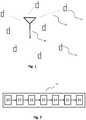
- Fig. 1shows a machine type communication scenario according to a preferred embodiment, comprising a receiver 10, e.g. a base station in a 4G wireless system or a 5G wireless system, and associated user equipment devices 12.
- User equipment devices 12 and receiver 10are located within the communication range of these devices and communication is performed via a transmission channel 14, which is e.g. a wireless transmission channel.
- a transmission channel 14which is e.g. a wireless transmission channel.
- a multi-carrier transmission systeme.g. OFDM or FBMC
- SC-FDMAsingle carrier transmission system
- a schematic overview of a receiver 10according to a preferred embodiment is shown. It is understood that only elements related to the invention are indicated in Fig. 2 but that a receiver 10 comprises additional means for performing its functionality. Such means are well known in the art and thus, are not mentioned explicitly.
- the receiver 10comprises an antenna 20, which is either an antenna for single-channel communication or multi-channel communication.
- the antenna 20is equipped to distinguish signals spatially. In e.g. antenna systems with controllable directivity like patch antenna arrays, input signals are distinguishable by their receiving direction.
- Such an embodimentcomprises a spatial discriminator 21 for analyzing the direction from which the signal is received.
- the receiver 10is equipped with multiple antenna elements which are e.g. phase-calibrated.
- the signals for each elementare received in an RF chain, including e.g. filtering, mixing, low noise amplification and analog-to-digital conversion.
- the spatial processingmay be performed in combination with the digital baseband processing of the multiple antenna inputs.
- Direction-finding algorithmslike MUSIC or ESPRIT may be used for spatial discremination.
- Other examplesinclude the usage of channel estimation based on training/pilot/reference symbols or by blind channel estimation methods. From the estimated channels, different metrics may be used to judge the spatial properties of the devices for spatial separation. In one embodiment, the channel covariance matrix of a device is deduced from the estimated channel, and then its largest eigenvector is computed.
- the receivercomprises a power measurement unit 22 for determining the power level of the signal received, e.g. based on pilot symbols or on blind channel estimation or, in case of spreading, based on the output power of a correlator.
- the receiver 10comprises a frequency detector 23 for determining the frequency on which a data packet is received.
- a spreading code detector 24for determining the spreading code sequence which was used for encoding the data packet is provided.
- the spreading code spaceis scanned by a correlator, measuring the output power of the different spreading sequences in order to detect activity.
- the spreading code detector 24performs a correlator-based tree-search of spreading subsequence sets, in case the data packet was encoded by a tree structure spreading code sequence, e.g. a Walsh-Hadamard sequence.
- the receiver 10comprises a look-up table 25 with the stored characteristics of the devices which are registered in order to determine the implicit user ID. Such a look-up table 25 contains e.g.
- an address decoder 26 for decoding an explicit address which is transmitted with the received data packetis provided.
- the explicit address and the implicit address IDare combined to identify the user equipment device 12.
- a data packet sent by a user equipment device 12is received 30.
- the data packetis received e.g. by a multi-carrier system or single-carrier system as described above.
- a transmission frequency of the received data packetis determined in step 31.
- the transmission frequencyis a sub-band or PRB or a hopping pattern of PRBs over time.
- the spreading code sequence of the data packet receivedis determined.
- the implicit code-based information of the data packetis analyzed.
- the spreading code sequencesare arranged in a tree structure, e.g. Walsh-Hadamard sequences, which can be efficiently scanned and analyzed.
- a correlator-based tree-search or other known methodsare used to determine the spreading code sequence sets and its subsequence sets.
- the location of the user equipment device 12 in correlation to the receiver 10is determined.
- a spatial signatureis determined in embodiments which allow spatial discrimination of received signals.
- the spatial signatureis the information in which direction from a viewpoint of the receiver 10 the corresponding user equipment device 12 is located. Determining the special signature is feasible, e.g. if the receiver 10 is equipped with several antennas 20.
- a spatial re-use between a set of user equipment devices 12can be done by assigning the same spreading code sequence and frequency including hopping pattern to different user equipment devices 12. Criteria for differentiating the spatial signature are e.g. different receive covariance matrices, clearly different directions of arrival, orthogonal uplink receive channel vectors and orthogonal preferred downlink precoding matrix indicators (PMI) from feedback signaling.
- PMIorthogonal uplink receive channel vectors
- PMIorthogonal preferred downlink precoding matrix indicators
- the sending power of the user equipment devices 12is known at the receiver 10.
- step 35the information determined in the preceding steps is compared to values stored in a look-up table 25.
- the look-up tablecontains characteristic values of the user equipment devices 12 with regard to the corresponding receiver 10.
- the implicit user IDis determined 37. If the received data packet contains also an explicit address, this address is determined in step 36.
- the user equipment device 12 which sent the received data packetis identified by the implicit user ID or by a combination of the implicit user ID and the explicit address. It is understood that the above described steps are not described in a chronological order. According to the invention, not necessarily all steps need to be performed for determining the implicit user ID and the sequence of performing the steps can be changed within the scope of the present invention.
- 2400 implicit user IDsare available using spreading code sequence and frequency as distinguishing feature.
- a receiver equipped with four antennas with such a large set of userscan easily find at least pairs of users being spatially orthogonal, thus increasing the implicit address space to 4800 devices.
- Using an eight bit explicit address in combination with the implicit user IDallows distinguishing more than a million user equipment devices 12 within the range of one receiver 10.
- DSPdigital signal processor
- ASICapplication specific integrated circuit
- FPGAfield programmable gate array
- ROMread only memory
- RAMrandom access memory
Landscapes
- Engineering & Computer Science (AREA)
- Computer Networks & Wireless Communication (AREA)
- Signal Processing (AREA)
- Databases & Information Systems (AREA)
- Mobile Radio Communication Systems (AREA)
- Telephonic Communication Services (AREA)
Description
- The present invention relates to a method for identifying a terminal or user equipment (UE) in a wireless system.
- This section introduces aspects that may be helpful in facilitating a better understanding of the invention. Accordingly, the statements of this section are to be read in this light and are not to be understood as admission about what is in the prior art.
- In enhanced 4G wireless systems and especially in future 5G wireless systems, a large number of devices, e.g. user equipment devices (UE), will be present in the coverage area of a base station, e.g. an eNodeB. Many of these devices access the network only sporadically. These devices are machine-type devices (MTC), e.g. sensor devices. Sporadic traffic may also be caused by smartphone applications which only carry a few bits in the uplink, e.g. for triggering updates, calling weather forecasts or newsfeed updates.
- In order to identify the user equipment devices, each device has its explicit address. When communicating with the base station, the explicit address has to be transmitted to the base station, causing overhead data. In case of a large number of user equipment devices, the explicit addresses need to provide a large address room, and hence the explicit addresses need to be long addresses. The longer the addresses are the more overhead data is produced. The overhead grows in relative size. When the amount of information data to be transmitted is comparatively small, the size of the actual explicit address data gets into the same order as the information data. This is the case e.g. in the mentioned MTC scenario.
- The classical way of handling a large number of users in 4G wireless systems, e.g. LTE-A systems, is to use active state (RRC_CONNECTED) and idle state (RRC_IDLE). Devices which are not expected to have data to transmit for a longer time period are in idle state.
- Devices which are idle or users which are active but not uplink-synchronized have to use the random access procedure before being able to transmit data. Furthermore, if there is no uplink resource allocated to a device for sending a scheduling request (SR), devices use the random access channel (RACH) to send a scheduling request (SR).
- A random access procedure contains the following steps:
- Preamble transmission;
- Random access response;
- Layer 2 / Layer 3 (L2/L3) message;
- Contention resolution message.
- In a future scenario with sporadic traffic and a large number of machine-type devices, e.g. the so called internet of things, these devices will waste resources by causing a huge random access procedure overhead.
- It is an object of the invention to enable efficient sporadic low-rate data transmission in such a scenario.
- According to one embodiment, a method for detecting an implicit user ID of a received data packet is proposed. When a data packet is received, at least one transmission parameter of the data packet is determined. An implicit user ID of the data packet received is determined in dependence of the at least one transmission parameter.
- A transmission parameter of the data packet received is to be understood as a parameter derivable from the data packet at the side of the receiver, e.g. the base station. Such a parameter is e.g. related to the coding of the data packet, a parameter of the RF signal used to transmit the data packet, etc. Examples of transmission parameters are discussed in the following.
- An implicit user ID is to be understood as information related to the origin of the data packet, which is derivable from the data packet itself, e.g. from the physical characteristics of the received signal carrying the data packet, the direction of origin of the received signal, the encoding scheme of the data packet, etc. While an explicit address is composed of additional bits added to the user data of a data packet as an overhead in order to identify the origin of the data packet, the implicit user ID is derivable from the transmitted user data itself without adding additional bits.
- Determining an implicit user ID of the data packet in dependence of the at least one determined transmission parameter has the advantage that transmission of explicit address data can be omitted, as the source of the data packet is determined by the implicit user ID. The information needed for determining the implicit user ID is available in the data packet anyway. Thus, no overhead data need to be sent to transmit such information and the overhead in the data transmission is reduced. Uplink synchronization is skipped for sporadic traffic. User equipment devices transmit their data right away in asynchronous manner. This is especially beneficial in future scenarios with a huge number of devices, each one generating only sporadic traffic on the network.
- In one embodiment, a transmission parameter of the received data packet is its spreading code sequence, which was used for encoding the data packet. The spreading code sequence is determined and is used to determine the implicit user ID. The spreading code sequence is necessary to demodulate the received data packet anyway, thus using the spreading code sequence to determine the implicit user ID has the advantage that information which is available anyway is used.
- In one embodiment, the spreading code sequence used for encoding the data packet, and thus the spreading code sequence determined by the method for detecting an implicit user ID is a tree structure spreading code sequence. An example for a tree structure spreading code sequence is e.g. a Walsh-Hadamard sequence. The spreading code sequence of a data packet which was encoded by a tree structure spreading code sequence is e.g. determined by a correlator-based tree-search of spreading subsequence sets. This reduces the processing complexity for determining the spreading code sequence significantly.
- In one embodiment, a transmission parameter of the received data packet is at least one frequency on which the data packet has been received. In case of frequency multiplexing, the frequency on which a data packet was received is a discriminator to identify different origins of the data packet.In one embodiment, the data packet is received via a multi-carrier transmission system. Multi-carrier transmission systems are e.g. orthogonal frequency division multiplexing (OFDM) or filter-bank based multi-carrier (FBMC) transmission systems. In such a system, sub-band information or physical resource blocks (PRBs) are used to determine the at least one frequency on which the data packet is received. Alternatively, or in addition, a set of PRBs or a hopping pattern across a set of PRBs over time is used to determine the at least one frequency on which the data packet is received. This information is derived during processing of the received data packet and is used to define the address space of the implicit user IDs. FBMC systems have the advantage that side-lobes of the asynchronous signals of different devices are much weaker and thus have reduced inter-carrier interference (ICI) between neighboring carriers of different devices.
- In one embodiment, the signal format is a combination of spreading and a multi-carrier transmission system, like multi-carrier CDMA (MC-CDMA), which is a combination of OFDM and CDMA. Instead of OFDM, other filter-bank-based multi-carrier techniques like FBMC may be used.In one embodiment, a single carrier system is used for transmission. Transmission systems using a single carrier are e.g. discrete fourier transform (DFT)-precoded OFDM transmission systems as a variant of single-carrier frequency-division multiple access (SC-FDMA) transmission systems.
- In one embodiment, a multi-antenna receiver is used for receiving the data packet. The multi-antenna receiver indicates the spatial direction from which the data packet is received and allows estimation of the location of the user. This spatial signature is used to determine the implicit user ID. This offers one further degree of freedom for assigning implicit user IDs and expands the address room of implicit user IDs. In machine-type communication (MTC) systems, using spatial properties is attractive as many user equipment devices are sensor devices, which typically do not move. Their spatial characteristic is rather stable and provides reliable information for an implicit user ID.
- In one embodiment, the power level of the signal of the received data packet is determined. In case the sender power is known, e.g. because it is the same for all user equipment devices, the received power level indicates the distance between the user equipment device and the receiver, as the attenuation of the signal is proportional to the distance between the user equipment device and the receiver. The determined power level is used to determine the implicit user ID. This offers one further degree of freedom for assigning implicit user IDs and expands the address room of implicit user IDs. In this way, the amount of implicit user IDs is significantly enhanced for applications that are employed over a large area.
- In one embodiment, a look-up table is provided with stored characteristics of the user equipment devices which are registered. The look-up table includes one or multiple of the above mentioned characteristics, e.g. frequency, spreading code sequence, spatial characteristic and power level. The look-up table provides a fast way to determine the implicit user ID of a data packet received by comparing the determined characteristics of the data packet and the characteristics stored in the look-up table.
- In one embodiment, the receiver assigns the implicit user ID characteristics to the user equipment devices e.g. using forward control signaling or higher layer control signaling.
- In one embodiment, the data packet received contains an explicit address of the user. The explicit address is transmitted in an address field within the transmitted data. The user equipment device is identified by a mix of implicit and explicit address information. This has the advantage that the address space provided by the explicit address is enhanced by combining it with the implicit user ID and thus, the overall address space is enhanced. On the other hand, if the address space of the implicit user ID is not large enough to support all user equipment devices in the range of the receiver, the implicit address space is enhanced by additional explicit addresses transmitted in combination with the data. Especially in machine type communication scenarios with many user devices, this enhancement of the address space is desirable.
- In one embodiment, an apparatus for receiving a data packet in a transmission system is proposed, wherein the apparatus performs a method according to the embodiments as described above.
- In one embodiment, a transmission system for sending a data packet from a sender to a receiver is proposed. The transmission system comprises at least one apparatus for sending a data packet. The apparatus for sending the data packet applies a spreading code sequence for coding the data packet to be sent. Further, the transmission system comprises at least one apparatus for receiving a data packet as described in the embodiment above.
- Some embodiments of apparatus and methods in accordance with embodiments of the present invention are now described, by way of examples only, and with reference to the accompanying drawings, in which:
- Fig. 1
- shows a machine-type communication scenario
- Fig. 2
- shows a schematic overview of a receiver device
- Fig. 3
- shows a flow chart for detecting an implicit user ID
- The description and drawings merely illustrate the principles of the invention. It will thus be appreciated that those skilled in the art will be able to devise various arrangements that, although not explicitly described or shown herein, embody the principles of the invention and are included within its spirit and scope. Furthermore, all examples recited herein are principally intended expressly to be only for pedagogical purposes to aid the reader in understanding the principles of the invention and the concepts contributed by the inventors to furthering the art, and are to be construed as being without limitation to such specifically recited examples and conditions. Moreover, all statements herein reciting principles, aspects, and embodiments of the invention, as well as specific examples thereof, are intended to encompass equivalents thereof.
Fig. 1 shows a machine type communication scenario according to a preferred embodiment, comprising areceiver 10, e.g. a base station in a 4G wireless system or a 5G wireless system, and associateduser equipment devices 12.User equipment devices 12 andreceiver 10 are located within the communication range of these devices and communication is performed via atransmission channel 14, which is e.g. a wireless transmission channel. For the communication, either a multi-carrier transmission system, e.g. OFDM or FBMC, or a single carrier transmission system, e.g. SC-FDMA or DFT-precoded OFDM, is used.- In
Fig. 2 , a schematic overview of areceiver 10 according to a preferred embodiment is shown. It is understood that only elements related to the invention are indicated inFig. 2 but that areceiver 10 comprises additional means for performing its functionality. Such means are well known in the art and thus, are not mentioned explicitly. Thereceiver 10 comprises an antenna 20, which is either an antenna for single-channel communication or multi-channel communication. According to one embodiment, the antenna 20 is equipped to distinguish signals spatially. In e.g. antenna systems with controllable directivity like patch antenna arrays, input signals are distinguishable by their receiving direction. Such an embodiment comprises a spatial discriminator 21 for analyzing the direction from which the signal is received. In one embodiment, thereceiver 10 is equipped with multiple antenna elements which are e.g. phase-calibrated. The signals for each element are received in an RF chain, including e.g. filtering, mixing, low noise amplification and analog-to-digital conversion. The spatial processing may be performed in combination with the digital baseband processing of the multiple antenna inputs. Direction-finding algorithms like MUSIC or ESPRIT may be used for spatial discremination. Other examples include the usage of channel estimation based on training/pilot/reference symbols or by blind channel estimation methods. From the estimated channels, different metrics may be used to judge the spatial properties of the devices for spatial separation. In one embodiment, the channel covariance matrix of a device is deduced from the estimated channel, and then its largest eigenvector is computed. In a typical macro-cellular environment, if the scalar product of this eigenvector with the largest eigenvector of another device is small, they are well separable in space. Thus, it is determined if signals of different devices lie in different subspaces. In one embodiment, the receiver comprises a power measurement unit 22 for determining the power level of the signal received, e.g. based on pilot symbols or on blind channel estimation or, in case of spreading, based on the output power of a correlator. Further, thereceiver 10 comprises a frequency detector 23 for determining the frequency on which a data packet is received. A spreading code detector 24 for determining the spreading code sequence which was used for encoding the data packet is provided. In one embodiment, the spreading code space is scanned by a correlator, measuring the output power of the different spreading sequences in order to detect activity. As device activity in a MTC system with sporadic traffic is sparse, also methods of compressed sensing may be used for activity detection of the respective spreading codes. In one embodiment, the spreading code detector 24 performs a correlator-based tree-search of spreading subsequence sets, in case the data packet was encoded by a tree structure spreading code sequence, e.g. a Walsh-Hadamard sequence. In one embodiment, thereceiver 10 comprises a look-up table 25 with the stored characteristics of the devices which are registered in order to determine the implicit user ID. Such a look-up table 25 contains e.g. possible combinations of spreading code and frequency and associates for each of those combinations one stored implicit user ID. In one embodiment, an address decoder 26 for decoding an explicit address which is transmitted with the received data packet is provided. The explicit address and the implicit address ID are combined to identify theuser equipment device 12. The structural elements described above are of exemplary nature only. It is understood that not all of these elements are necessarily present when implementing the invention and a change of their sequence is also within the scope of the invention. Examples given for the structural elements are only to support understanding of the invention and do not restrict the implementation to these examples. - In
Fig. 3 , a schematic overview for identifying auser equipment device 12 and for detecting an implicit user ID of auser equipment device 12 by areceiver 10, e.g. a base station, is disclosed. First, a data packet sent by auser equipment device 12 is received 30. The data packet is received e.g. by a multi-carrier system or single-carrier system as described above. A transmission frequency of the received data packet is determined instep 31. In a multi-carrier system, the transmission frequency is a sub-band or PRB or a hopping pattern of PRBs over time. Instep 32, the spreading code sequence of the data packet received is determined. Thus, the implicit code-based information of the data packet is analyzed. In one embodiment, the spreading code sequences are arranged in a tree structure, e.g. Walsh-Hadamard sequences, which can be efficiently scanned and analyzed. A correlator-based tree-search or other known methods are used to determine the spreading code sequence sets and its subsequence sets. In one embodiment, the location of theuser equipment device 12 in correlation to thereceiver 10 is determined. Instep 33, a spatial signature is determined in embodiments which allow spatial discrimination of received signals. The spatial signature is the information in which direction from a viewpoint of thereceiver 10 the correspondinguser equipment device 12 is located. Determining the special signature is feasible, e.g. if thereceiver 10 is equipped with several antennas 20. If the spatial signature clearly differs, a spatial re-use between a set ofuser equipment devices 12 can be done by assigning the same spreading code sequence and frequency including hopping pattern to differentuser equipment devices 12. Criteria for differentiating the spatial signature are e.g. different receive covariance matrices, clearly different directions of arrival, orthogonal uplink receive channel vectors and orthogonal preferred downlink precoding matrix indicators (PMI) from feedback signaling. In one embodiment, in order to further determine the location of theuser equipment device 12 in correlation to thereceiver 10, the distance between theuser equipment device 12 and the receiver is determined instep 34. A measure for this distance is the signal power received at thereceiver 10, provided that the signal power which has been used for sending the data packet by theuser equipment device 12 is known. In MTC scenarios using sensor devices as described above, the sending power of theuser equipment devices 12 is known at thereceiver 10. Instep 35, the information determined in the preceding steps is compared to values stored in a look-up table 25. The look-up table contains characteristic values of theuser equipment devices 12 with regard to the correspondingreceiver 10. Using these values, the implicit user ID is determined 37. If the received data packet contains also an explicit address, this address is determined instep 36. Afterwards, theuser equipment device 12 which sent the received data packet is identified by the implicit user ID or by a combination of the implicit user ID and the explicit address. It is understood that the above described steps are not described in a chronological order. According to the invention, not necessarily all steps need to be performed for determining the implicit user ID and the sequence of performing the steps can be changed within the scope of the present invention. - In an exemplary embodiment with 100 PRBs and a spreading factor of 24, in case of one PRB transmission, 2400 implicit user IDs are available using spreading code sequence and frequency as distinguishing feature. A receiver equipped with four antennas with such a large set of users can easily find at least pairs of users being spatially orthogonal, thus increasing the implicit address space to 4800 devices. Using an eight bit explicit address in combination with the implicit user ID allows distinguishing more than a million
user equipment devices 12 within the range of onereceiver 10. - The functions of the various elements shown in the Figures, including any functional blocks, may be provided through the use of dedicated hardware as well as hardware capable of executing software in association with appropriate software. When provided by a processor, the functions may be provided by a single dedicated processor, by a single shared processor, or by a plurality of individual processors, some of which may be shared. Moreover, the functions may be provided, without limitation, by digital signal processor (DSP) hardware, network processor, application specific integrated circuit (ASIC), field programmable gate array (FPGA), read only memory (ROM) for storing software, random access memory (RAM), and non volatile storage. Other hardware, conventional and/or custom, may also be included.
Claims (14)
- Method for detecting an implicit user ID of a received data packet, comprising the steps:- receiving (30) a data packet composed of at least user data and an additional explicit address,- determining (36) the explicit address of the received data packet,- determining at least one transmission parameter of the user data of the received data packet,- determining (37) an implicit user ID of the data packet in dependence of the at least one determined transmission parameter, and- combining the implicit user ID and the explicit address to identify the origin of the data packet.
- Method for detecting an implicit user ID according to claim 1, wherein the step of determining at least one transmission parameter comprises:- determining (32) a spreading code sequence of the received data packet.
- Method for detecting an implicit user ID according to claim 2, wherein the spreading code sequence determined is a tree structure spreading code sequence.
- Method for detecting an implicit user ID according to one of claims 1 to 3, wherein the step of determining at least one transmission parameter comprises:- determining (31) at least one frequency on which the data packet has been received.
- Method for detecting an implicit user ID according to one of claims 1 to 4, wherein the data packet is received via a multi-carrier transmission system.
- Method for detecting an implicit user ID according to claim 4, wherein the determined at least one frequency corresponds to a physical resource block, a set of physical resource blocks or a hopping pattern across a set of physical resource blocks.
- Method for detecting an implicit user ID according to one of claims 1 to 3, wherein the data packet is received via an SC-FDMA or a DFT-precoded OFDM transmission system.
- Method for detecting an implicit user ID according to claim 5 or 6, wherein the data packet is received via an OFDM or an FBMC transmission system.
- Method for detecting an implicit user ID according to one of claims 1 to 6, wherein the step of determining at least one transmission parameter comprises:- determining (33) the spatial signature of the received data packet in a multi-antenna receiver.
- Method for detecting an implicit user ID according to one of claims 1 to 9, wherein the step of determining at least one transmission parameter comprises:- determining (34) the power level of the received data packet.
- Method for detecting an implicit user ID according to one of claims 1 to 10, further comprising the step:- comparing (35) the determined transmission parameters of the received data packet with stored characteristics of user equipment devices registered, the characteristics of devices registered being stored in a look-up table.
- Method for detecting an implicit user ID according to one of claims 1 to 11, further comprising the step- assigning characteristics to the user equipment devices by forward control signaling or higher layer control signaling.
- Apparatus (10) for receiving a data packet in a transmission system, wherein the apparatus performs a method according to one of claims 1 to 12.
- Transmission system for sending a data packet from a sender (12) to a receiver (10), wherein the transmission system comprises at least one apparatus for sending (12) a data packet, the apparatus for sending (12) the data packet applies a spreading code sequence for coding the data packet to be sent and the transmission system further comprises at least one apparatus for receiving (10) a data packet according to claim 13.
Priority Applications (7)
| Application Number | Priority Date | Filing Date | Title |
|---|---|---|---|
| EP13305377.7AEP2785077B1 (en) | 2013-03-27 | 2013-03-27 | Implicit addressing for sporadic machine-type access |
| KR1020157026334AKR20150121171A (en) | 2013-03-27 | 2014-03-17 | Implicit addressing for sporadic machine-type access |
| US14/779,443US20160057755A1 (en) | 2013-03-27 | 2014-03-17 | Implicit addressing for sporadic machine-type access |
| CN201480018357.0ACN105103572A (en) | 2013-03-27 | 2014-03-17 | Implicit addressing for sporadic machine type access |
| PCT/EP2014/055327WO2014154518A1 (en) | 2013-03-27 | 2014-03-17 | Implicit addressing for sporadic machine-type access |
| JP2016504563AJP6158419B2 (en) | 2013-03-27 | 2014-03-17 | Implicit addressing for sporadic machine-type access |
| TW103110489ATWI562577B (en) | 2013-03-27 | 2014-03-20 | Implicit addressing for sporadic machine-type access |
Applications Claiming Priority (1)
| Application Number | Priority Date | Filing Date | Title |
|---|---|---|---|
| EP13305377.7AEP2785077B1 (en) | 2013-03-27 | 2013-03-27 | Implicit addressing for sporadic machine-type access |
Publications (2)
| Publication Number | Publication Date |
|---|---|
| EP2785077A1 EP2785077A1 (en) | 2014-10-01 |
| EP2785077B1true EP2785077B1 (en) | 2017-08-30 |
Family
ID=48193225
Family Applications (1)
| Application Number | Title | Priority Date | Filing Date |
|---|---|---|---|
| EP13305377.7ANot-in-forceEP2785077B1 (en) | 2013-03-27 | 2013-03-27 | Implicit addressing for sporadic machine-type access |
Country Status (7)
| Country | Link |
|---|---|
| US (1) | US20160057755A1 (en) |
| EP (1) | EP2785077B1 (en) |
| JP (1) | JP6158419B2 (en) |
| KR (1) | KR20150121171A (en) |
| CN (1) | CN105103572A (en) |
| TW (1) | TWI562577B (en) |
| WO (1) | WO2014154518A1 (en) |
Families Citing this family (5)
| Publication number | Priority date | Publication date | Assignee | Title |
|---|---|---|---|---|
| US10128897B2 (en)* | 2016-05-26 | 2018-11-13 | Huawei Technologies Co., Ltd. | Two-phase transmission for machine-type communication |
| CN106452501B (en)* | 2016-09-30 | 2019-06-14 | 华中科技大学 | Construction of Real-Virtual Interleaved Four-phase Sequence and MSK/GMSK Synchronization Method and Spread Spectrum System |
| CN111201828B (en)* | 2017-10-12 | 2022-05-06 | 中兴通讯股份有限公司 | System and method for identifying communication nodes |
| CN109462443B (en)* | 2018-12-05 | 2021-07-02 | 唐山照澜海洋科技有限公司 | 5G multi-carrier underwater acoustic communication method |
| EP3912048B1 (en)* | 2019-01-15 | 2023-07-19 | Heldeis, Christoph | Method for implicit addressing of electronic units and corresponding units |
Family Cites Families (16)
| Publication number | Priority date | Publication date | Assignee | Title |
|---|---|---|---|---|
| US7054294B2 (en)* | 2001-11-29 | 2006-05-30 | Telefonaktiebolaget Lm Ericsson (Publ) | Orthogonal variable spreading code (OVSF) allocation telecommunications network |
| US8208364B2 (en)* | 2002-10-25 | 2012-06-26 | Qualcomm Incorporated | MIMO system with multiple spatial multiplexing modes |
| US7562383B2 (en)* | 2005-04-20 | 2009-07-14 | Fuji Xerox Co., Ltd. | Systems and methods for a dynamic user interface proxy using physical keys |
| US8363603B2 (en)* | 2005-06-16 | 2013-01-29 | Qualcomm Incorporated | User separation in space division multiple access for a multi-carrier communication system |
| EP2058967A1 (en)* | 2007-11-09 | 2009-05-13 | Nokia Siemens Networks Oy | Spatial division multiple access for high speed packet access modes |
| WO2010067598A1 (en)* | 2008-12-10 | 2010-06-17 | パナソニック株式会社 | Wireless communication terminal apparatus, wireless communication base station apparatus and signal spreading method |
| CN102378309B (en)* | 2010-08-12 | 2014-04-30 | 华为技术有限公司 | Network access method and system thereof |
| US20120083204A1 (en)* | 2010-10-04 | 2012-04-05 | Nokia Corporation | Method and Apparatus for Controlling Access |
| GB2484922B (en)* | 2010-10-25 | 2014-10-08 | Sca Ipla Holdings Inc | Infrastructure equipment and method |
| US9042327B2 (en)* | 2010-11-18 | 2015-05-26 | Lg Electronics Inc. | Method for transmitting control information and a device therefor |
| US8634849B2 (en)* | 2011-01-19 | 2014-01-21 | Qualcomm Incorporated | Methods and apparatus for mobile device based location determination in a communications system |
| EP2487985A1 (en)* | 2011-02-09 | 2012-08-15 | Alcatel Lucent | Apparatuses and methods for transmission of a radio coverage request |
| TWI452922B (en)* | 2011-04-18 | 2014-09-11 | Innovative Sonic Corp | Method and apparatus to prevent radio access network (ran) overload in a wireless communication system |
| US20120281647A1 (en)* | 2011-05-03 | 2012-11-08 | Innovative Sonic Corporation | Method and apparatus to improve machine type communication in a wireless communication system |
| GB2491840B (en)* | 2011-06-13 | 2015-09-16 | Neul Ltd | Inter-device communication |
| US9130798B1 (en)* | 2011-09-23 | 2015-09-08 | Sprint Communications Company L.P. | Managing internet protocol address allocation |
- 2013
- 2013-03-27EPEP13305377.7Apatent/EP2785077B1/ennot_activeNot-in-force
- 2014
- 2014-03-17USUS14/779,443patent/US20160057755A1/ennot_activeAbandoned
- 2014-03-17KRKR1020157026334Apatent/KR20150121171A/ennot_activeCeased
- 2014-03-17WOPCT/EP2014/055327patent/WO2014154518A1/enactiveApplication Filing
- 2014-03-17JPJP2016504563Apatent/JP6158419B2/ennot_activeExpired - Fee Related
- 2014-03-17CNCN201480018357.0Apatent/CN105103572A/enactivePending
- 2014-03-20TWTW103110489Apatent/TWI562577B/ennot_activeIP Right Cessation
Non-Patent Citations (1)
| Title |
|---|
| None* |
Also Published As
| Publication number | Publication date |
|---|---|
| TW201445948A (en) | 2014-12-01 |
| KR20150121171A (en) | 2015-10-28 |
| CN105103572A (en) | 2015-11-25 |
| TWI562577B (en) | 2016-12-11 |
| US20160057755A1 (en) | 2016-02-25 |
| WO2014154518A1 (en) | 2014-10-02 |
| EP2785077A1 (en) | 2014-10-01 |
| JP2016519883A (en) | 2016-07-07 |
| JP6158419B2 (en) | 2017-07-05 |
Similar Documents
| Publication | Publication Date | Title |
|---|---|---|
| EP3334080B1 (en) | Data transmission method and device | |
| EP3275092B1 (en) | Systems and methods for selecting beam-reference signals for channel-state information reference-signal transmission | |
| JP6377860B2 (en) | Method and device for generating and detecting a random access preamble | |
| EP3337254B1 (en) | Uplink detection method and apparatus in non-orthogonal multiple access system, and base station | |
| US11184136B2 (en) | Transmission of data by multiple users over shared resources based on structured superposition coding | |
| US20190288823A1 (en) | Signaling of Measurement Signals based on a Tree Structure | |
| EP2785077B1 (en) | Implicit addressing for sporadic machine-type access | |
| CN107615726A (en) | Method and device for transmitting pilot sequence | |
| CN108293233B (en) | Uplink Pilot Reference Signal | |
| CN110870217B (en) | Specular Component Estimation in Wireless Communication Networks | |
| KR102547003B1 (en) | Method and apparatus for random access in mobile communication system | |
| CN111164908B (en) | Interference aware packet transmission | |
| JPWO2018127955A1 (en) | Base station apparatus, terminal apparatus and transmission method | |
| WO2023225845A1 (en) | Reference signal assignment | |
| EP3763161B1 (en) | Selecting transmission response message transmitter | |
| KR20140125633A (en) | Method and apparatus for transmitting and receiving discovery signal for device to device communication | |
| EP3119023A1 (en) | Methods for multiplexing and assigning upink reference signals in a radio communication system with a first network node and a second network node | |
| KR101970891B1 (en) | Device and Method for Scheduling in Full-Duplex and Massive MIMO WLAN System | |
| KR20150099404A (en) | Method and apparatus for informing control information |
Legal Events
| Date | Code | Title | Description |
|---|---|---|---|
| 17P | Request for examination filed | Effective date:20140121 | |
| AK | Designated contracting states | Kind code of ref document:A1 Designated state(s):AL AT BE BG CH CY CZ DE DK EE ES FI FR GB GR HR HU IE IS IT LI LT LU LV MC MK MT NL NO PL PT RO RS SE SI SK SM TR | |
| AX | Request for extension of the european patent | Extension state:BA ME | |
| PUAI | Public reference made under article 153(3) epc to a published international application that has entered the european phase | Free format text:ORIGINAL CODE: 0009012 | |
| RBV | Designated contracting states (corrected) | Designated state(s):AL AT BE BG CH CY CZ DE DK EE ES FI FR GB GR HR HU IE IS IT LI LT LU LV MC MK MT NL NO PL PT RO RS SE SI SK SM TR | |
| GRAP | Despatch of communication of intention to grant a patent | Free format text:ORIGINAL CODE: EPIDOSNIGR1 | |
| INTG | Intention to grant announced | Effective date:20170315 | |
| GRAS | Grant fee paid | Free format text:ORIGINAL CODE: EPIDOSNIGR3 | |
| GRAA | (expected) grant | Free format text:ORIGINAL CODE: 0009210 | |
| AK | Designated contracting states | Kind code of ref document:B1 Designated state(s):AL AT BE BG CH CY CZ DE DK EE ES FI FR GB GR HR HU IE IS IT LI LT LU LV MC MK MT NL NO PL PT RO RS SE SI SK SM TR | |
| REG | Reference to a national code | Ref country code:GB Ref legal event code:FG4D | |
| REG | Reference to a national code | Ref country code:CH Ref legal event code:EP | |
| REG | Reference to a national code | Ref country code:AT Ref legal event code:REF Ref document number:924708 Country of ref document:AT Kind code of ref document:T Effective date:20170915 | |
| REG | Reference to a national code | Ref country code:IE Ref legal event code:FG4D | |
| REG | Reference to a national code | Ref country code:DE Ref legal event code:R096 Ref document number:602013025734 Country of ref document:DE | |
| REG | Reference to a national code | Ref country code:NL Ref legal event code:MP Effective date:20170830 | |
| REG | Reference to a national code | Ref country code:LT Ref legal event code:MG4D | |
| REG | Reference to a national code | Ref country code:AT Ref legal event code:MK05 Ref document number:924708 Country of ref document:AT Kind code of ref document:T Effective date:20170830 | |
| PG25 | Lapsed in a contracting state [announced via postgrant information from national office to epo] | Ref country code:LT Free format text:LAPSE BECAUSE OF FAILURE TO SUBMIT A TRANSLATION OF THE DESCRIPTION OR TO PAY THE FEE WITHIN THE PRESCRIBED TIME-LIMIT Effective date:20170830 Ref country code:SE Free format text:LAPSE BECAUSE OF FAILURE TO SUBMIT A TRANSLATION OF THE DESCRIPTION OR TO PAY THE FEE WITHIN THE PRESCRIBED TIME-LIMIT Effective date:20170830 Ref country code:FI Free format text:LAPSE BECAUSE OF FAILURE TO SUBMIT A TRANSLATION OF THE DESCRIPTION OR TO PAY THE FEE WITHIN THE PRESCRIBED TIME-LIMIT Effective date:20170830 Ref country code:HR Free format text:LAPSE BECAUSE OF FAILURE TO SUBMIT A TRANSLATION OF THE DESCRIPTION OR TO PAY THE FEE WITHIN THE PRESCRIBED TIME-LIMIT Effective date:20170830 Ref country code:NO Free format text:LAPSE BECAUSE OF FAILURE TO SUBMIT A TRANSLATION OF THE DESCRIPTION OR TO PAY THE FEE WITHIN THE PRESCRIBED TIME-LIMIT Effective date:20171130 Ref country code:AT Free format text:LAPSE BECAUSE OF FAILURE TO SUBMIT A TRANSLATION OF THE DESCRIPTION OR TO PAY THE FEE WITHIN THE PRESCRIBED TIME-LIMIT Effective date:20170830 | |
| PG25 | Lapsed in a contracting state [announced via postgrant information from national office to epo] | Ref country code:ES Free format text:LAPSE BECAUSE OF FAILURE TO SUBMIT A TRANSLATION OF THE DESCRIPTION OR TO PAY THE FEE WITHIN THE PRESCRIBED TIME-LIMIT Effective date:20170830 Ref country code:RS Free format text:LAPSE BECAUSE OF FAILURE TO SUBMIT A TRANSLATION OF THE DESCRIPTION OR TO PAY THE FEE WITHIN THE PRESCRIBED TIME-LIMIT Effective date:20170830 Ref country code:BG Free format text:LAPSE BECAUSE OF FAILURE TO SUBMIT A TRANSLATION OF THE DESCRIPTION OR TO PAY THE FEE WITHIN THE PRESCRIBED TIME-LIMIT Effective date:20171130 Ref country code:LV Free format text:LAPSE BECAUSE OF FAILURE TO SUBMIT A TRANSLATION OF THE DESCRIPTION OR TO PAY THE FEE WITHIN THE PRESCRIBED TIME-LIMIT Effective date:20170830 Ref country code:IS Free format text:LAPSE BECAUSE OF FAILURE TO SUBMIT A TRANSLATION OF THE DESCRIPTION OR TO PAY THE FEE WITHIN THE PRESCRIBED TIME-LIMIT Effective date:20171230 Ref country code:GR Free format text:LAPSE BECAUSE OF FAILURE TO SUBMIT A TRANSLATION OF THE DESCRIPTION OR TO PAY THE FEE WITHIN THE PRESCRIBED TIME-LIMIT Effective date:20171201 | |
| REG | Reference to a national code | Ref country code:CH Ref legal event code:PCOW Free format text:NEW ADDRESS: SITE NOKIA PARIS SACLAY ROUTE DE VILLEJUST, 91620 NOZAY (FR) | |
| PG25 | Lapsed in a contracting state [announced via postgrant information from national office to epo] | Ref country code:NL Free format text:LAPSE BECAUSE OF FAILURE TO SUBMIT A TRANSLATION OF THE DESCRIPTION OR TO PAY THE FEE WITHIN THE PRESCRIBED TIME-LIMIT Effective date:20170830 | |
| RAP2 | Party data changed (patent owner data changed or rights of a patent transferred) | Owner name:ALCATEL LUCENT | |
| PG25 | Lapsed in a contracting state [announced via postgrant information from national office to epo] | Ref country code:DK Free format text:LAPSE BECAUSE OF FAILURE TO SUBMIT A TRANSLATION OF THE DESCRIPTION OR TO PAY THE FEE WITHIN THE PRESCRIBED TIME-LIMIT Effective date:20170830 Ref country code:CZ Free format text:LAPSE BECAUSE OF FAILURE TO SUBMIT A TRANSLATION OF THE DESCRIPTION OR TO PAY THE FEE WITHIN THE PRESCRIBED TIME-LIMIT Effective date:20170830 Ref country code:PL Free format text:LAPSE BECAUSE OF FAILURE TO SUBMIT A TRANSLATION OF THE DESCRIPTION OR TO PAY THE FEE WITHIN THE PRESCRIBED TIME-LIMIT Effective date:20170830 Ref country code:RO Free format text:LAPSE BECAUSE OF FAILURE TO SUBMIT A TRANSLATION OF THE DESCRIPTION OR TO PAY THE FEE WITHIN THE PRESCRIBED TIME-LIMIT Effective date:20170830 | |
| PG25 | Lapsed in a contracting state [announced via postgrant information from national office to epo] | Ref country code:SM Free format text:LAPSE BECAUSE OF FAILURE TO SUBMIT A TRANSLATION OF THE DESCRIPTION OR TO PAY THE FEE WITHIN THE PRESCRIBED TIME-LIMIT Effective date:20170830 Ref country code:SK Free format text:LAPSE BECAUSE OF FAILURE TO SUBMIT A TRANSLATION OF THE DESCRIPTION OR TO PAY THE FEE WITHIN THE PRESCRIBED TIME-LIMIT Effective date:20170830 Ref country code:EE Free format text:LAPSE BECAUSE OF FAILURE TO SUBMIT A TRANSLATION OF THE DESCRIPTION OR TO PAY THE FEE WITHIN THE PRESCRIBED TIME-LIMIT Effective date:20170830 Ref country code:IT Free format text:LAPSE BECAUSE OF FAILURE TO SUBMIT A TRANSLATION OF THE DESCRIPTION OR TO PAY THE FEE WITHIN THE PRESCRIBED TIME-LIMIT Effective date:20170830 | |
| REG | Reference to a national code | Ref country code:DE Ref legal event code:R097 Ref document number:602013025734 Country of ref document:DE | |
| PLBE | No opposition filed within time limit | Free format text:ORIGINAL CODE: 0009261 | |
| STAA | Information on the status of an ep patent application or granted ep patent | Free format text:STATUS: NO OPPOSITION FILED WITHIN TIME LIMIT | |
| 26N | No opposition filed | Effective date:20180531 | |
| PG25 | Lapsed in a contracting state [announced via postgrant information from national office to epo] | Ref country code:SI Free format text:LAPSE BECAUSE OF FAILURE TO SUBMIT A TRANSLATION OF THE DESCRIPTION OR TO PAY THE FEE WITHIN THE PRESCRIBED TIME-LIMIT Effective date:20170830 | |
| REG | Reference to a national code | Ref country code:DE Ref legal event code:R119 Ref document number:602013025734 Country of ref document:DE | |
| REG | Reference to a national code | Ref country code:CH Ref legal event code:PL | |
| GBPC | Gb: european patent ceased through non-payment of renewal fee | Effective date:20180327 | |
| PG25 | Lapsed in a contracting state [announced via postgrant information from national office to epo] | Ref country code:MC Free format text:LAPSE BECAUSE OF FAILURE TO SUBMIT A TRANSLATION OF THE DESCRIPTION OR TO PAY THE FEE WITHIN THE PRESCRIBED TIME-LIMIT Effective date:20170830 | |
| REG | Reference to a national code | Ref country code:BE Ref legal event code:MM Effective date:20180331 | |
| REG | Reference to a national code | Ref country code:IE Ref legal event code:MM4A | |
| PG25 | Lapsed in a contracting state [announced via postgrant information from national office to epo] | Ref country code:LU Free format text:LAPSE BECAUSE OF NON-PAYMENT OF DUE FEES Effective date:20180327 | |
| PG25 | Lapsed in a contracting state [announced via postgrant information from national office to epo] | Ref country code:IE Free format text:LAPSE BECAUSE OF NON-PAYMENT OF DUE FEES Effective date:20180327 Ref country code:DE Free format text:LAPSE BECAUSE OF NON-PAYMENT OF DUE FEES Effective date:20181002 | |
| PG25 | Lapsed in a contracting state [announced via postgrant information from national office to epo] | Ref country code:CH Free format text:LAPSE BECAUSE OF NON-PAYMENT OF DUE FEES Effective date:20180331 Ref country code:BE Free format text:LAPSE BECAUSE OF NON-PAYMENT OF DUE FEES Effective date:20180331 Ref country code:LI Free format text:LAPSE BECAUSE OF NON-PAYMENT OF DUE FEES Effective date:20180331 Ref country code:GB Free format text:LAPSE BECAUSE OF NON-PAYMENT OF DUE FEES Effective date:20180327 | |
| PG25 | Lapsed in a contracting state [announced via postgrant information from national office to epo] | Ref country code:FR Free format text:LAPSE BECAUSE OF NON-PAYMENT OF DUE FEES Effective date:20180331 | |
| PG25 | Lapsed in a contracting state [announced via postgrant information from national office to epo] | Ref country code:MT Free format text:LAPSE BECAUSE OF NON-PAYMENT OF DUE FEES Effective date:20180327 | |
| PG25 | Lapsed in a contracting state [announced via postgrant information from national office to epo] | Ref country code:TR Free format text:LAPSE BECAUSE OF FAILURE TO SUBMIT A TRANSLATION OF THE DESCRIPTION OR TO PAY THE FEE WITHIN THE PRESCRIBED TIME-LIMIT Effective date:20170830 | |
| PG25 | Lapsed in a contracting state [announced via postgrant information from national office to epo] | Ref country code:HU Free format text:LAPSE BECAUSE OF FAILURE TO SUBMIT A TRANSLATION OF THE DESCRIPTION OR TO PAY THE FEE WITHIN THE PRESCRIBED TIME-LIMIT; INVALID AB INITIO Effective date:20130327 Ref country code:PT Free format text:LAPSE BECAUSE OF FAILURE TO SUBMIT A TRANSLATION OF THE DESCRIPTION OR TO PAY THE FEE WITHIN THE PRESCRIBED TIME-LIMIT Effective date:20170830 | |
| PG25 | Lapsed in a contracting state [announced via postgrant information from national office to epo] | Ref country code:MK Free format text:LAPSE BECAUSE OF NON-PAYMENT OF DUE FEES Effective date:20170830 Ref country code:CY Free format text:LAPSE BECAUSE OF FAILURE TO SUBMIT A TRANSLATION OF THE DESCRIPTION OR TO PAY THE FEE WITHIN THE PRESCRIBED TIME-LIMIT Effective date:20170830 | |
| PG25 | Lapsed in a contracting state [announced via postgrant information from national office to epo] | Ref country code:AL Free format text:LAPSE BECAUSE OF FAILURE TO SUBMIT A TRANSLATION OF THE DESCRIPTION OR TO PAY THE FEE WITHIN THE PRESCRIBED TIME-LIMIT Effective date:20170830 | |
| REG | Reference to a national code | Ref country code:DE Ref legal event code:R081 Ref document number:602013025734 Country of ref document:DE Owner name:WSOU INVESTMENTS, LLC, LOS ANGELES, US Free format text:FORMER OWNER: ALCATEL LUCENT, BOULOGNE BILLANCOURT, FR |