EP2784718B1 - Communication apparatus, computer-readable storage medium, and communication method - Google Patents
Communication apparatus, computer-readable storage medium, and communication methodDownload PDFInfo
- Publication number
- EP2784718B1 EP2784718B1EP14167292.3AEP14167292AEP2784718B1EP 2784718 B1EP2784718 B1EP 2784718B1EP 14167292 AEP14167292 AEP 14167292AEP 2784718 B1EP2784718 B1EP 2784718B1
- Authority
- EP
- European Patent Office
- Prior art keywords
- communication
- power
- communication apparatus
- electrical power
- another
- Prior art date
- Legal status (The legal status is an assumption and is not a legal conclusion. Google has not performed a legal analysis and makes no representation as to the accuracy of the status listed.)
- Active
Links
Images


Classifications
- H—ELECTRICITY
- H04—ELECTRIC COMMUNICATION TECHNIQUE
- H04B—TRANSMISSION
- H04B5/00—Near-field transmission systems, e.g. inductive or capacitive transmission systems
- H04B5/70—Near-field transmission systems, e.g. inductive or capacitive transmission systems specially adapted for specific purposes
- H04B5/79—Near-field transmission systems, e.g. inductive or capacitive transmission systems specially adapted for specific purposes for data transfer in combination with power transfer
- G—PHYSICS
- G06—COMPUTING OR CALCULATING; COUNTING
- G06K—GRAPHICAL DATA READING; PRESENTATION OF DATA; RECORD CARRIERS; HANDLING RECORD CARRIERS
- G06K19/00—Record carriers for use with machines and with at least a part designed to carry digital markings
- G06K19/06—Record carriers for use with machines and with at least a part designed to carry digital markings characterised by the kind of the digital marking, e.g. shape, nature, code
- G06K19/067—Record carriers with conductive marks, printed circuits or semiconductor circuit elements, e.g. credit or identity cards also with resonating or responding marks without active components
- G06K19/07—Record carriers with conductive marks, printed circuits or semiconductor circuit elements, e.g. credit or identity cards also with resonating or responding marks without active components with integrated circuit chips
- G06K19/0701—Record carriers with conductive marks, printed circuits or semiconductor circuit elements, e.g. credit or identity cards also with resonating or responding marks without active components with integrated circuit chips at least one of the integrated circuit chips comprising an arrangement for power management
- G06K19/0715—Record carriers with conductive marks, printed circuits or semiconductor circuit elements, e.g. credit or identity cards also with resonating or responding marks without active components with integrated circuit chips at least one of the integrated circuit chips comprising an arrangement for power management the arrangement including means to regulate power transfer to the integrated circuit
- G—PHYSICS
- G06—COMPUTING OR CALCULATING; COUNTING
- G06K—GRAPHICAL DATA READING; PRESENTATION OF DATA; RECORD CARRIERS; HANDLING RECORD CARRIERS
- G06K19/00—Record carriers for use with machines and with at least a part designed to carry digital markings
- G06K19/06—Record carriers for use with machines and with at least a part designed to carry digital markings characterised by the kind of the digital marking, e.g. shape, nature, code
- G06K19/067—Record carriers with conductive marks, printed circuits or semiconductor circuit elements, e.g. credit or identity cards also with resonating or responding marks without active components
- G06K19/07—Record carriers with conductive marks, printed circuits or semiconductor circuit elements, e.g. credit or identity cards also with resonating or responding marks without active components with integrated circuit chips
- G06K19/0723—Record carriers with conductive marks, printed circuits or semiconductor circuit elements, e.g. credit or identity cards also with resonating or responding marks without active components with integrated circuit chips the record carrier comprising an arrangement for non-contact communication, e.g. wireless communication circuits on transponder cards, non-contact smart cards or RFIDs
- G—PHYSICS
- G06—COMPUTING OR CALCULATING; COUNTING
- G06K—GRAPHICAL DATA READING; PRESENTATION OF DATA; RECORD CARRIERS; HANDLING RECORD CARRIERS
- G06K7/00—Methods or arrangements for sensing record carriers, e.g. for reading patterns
- G06K7/0008—General problems related to the reading of electronic memory record carriers, independent of its reading method, e.g. power transfer
- G—PHYSICS
- G06—COMPUTING OR CALCULATING; COUNTING
- G06K—GRAPHICAL DATA READING; PRESENTATION OF DATA; RECORD CARRIERS; HANDLING RECORD CARRIERS
- G06K7/00—Methods or arrangements for sensing record carriers, e.g. for reading patterns
- G06K7/10—Methods or arrangements for sensing record carriers, e.g. for reading patterns by electromagnetic radiation, e.g. optical sensing; by corpuscular radiation
- G06K7/10009—Methods or arrangements for sensing record carriers, e.g. for reading patterns by electromagnetic radiation, e.g. optical sensing; by corpuscular radiation sensing by radiation using wavelengths larger than 0.1 mm, e.g. radio-waves or microwaves
- G06K7/10316—Methods or arrangements for sensing record carriers, e.g. for reading patterns by electromagnetic radiation, e.g. optical sensing; by corpuscular radiation sensing by radiation using wavelengths larger than 0.1 mm, e.g. radio-waves or microwaves using at least one antenna particularly designed for interrogating the wireless record carriers
- G06K7/10336—Methods or arrangements for sensing record carriers, e.g. for reading patterns by electromagnetic radiation, e.g. optical sensing; by corpuscular radiation sensing by radiation using wavelengths larger than 0.1 mm, e.g. radio-waves or microwaves using at least one antenna particularly designed for interrogating the wireless record carriers the antenna being of the near field type, inductive coil
- H—ELECTRICITY
- H02—GENERATION; CONVERSION OR DISTRIBUTION OF ELECTRIC POWER
- H02J—CIRCUIT ARRANGEMENTS OR SYSTEMS FOR SUPPLYING OR DISTRIBUTING ELECTRIC POWER; SYSTEMS FOR STORING ELECTRIC ENERGY
- H02J50/00—Circuit arrangements or systems for wireless supply or distribution of electric power
- H02J50/10—Circuit arrangements or systems for wireless supply or distribution of electric power using inductive coupling
- H—ELECTRICITY
- H02—GENERATION; CONVERSION OR DISTRIBUTION OF ELECTRIC POWER
- H02J—CIRCUIT ARRANGEMENTS OR SYSTEMS FOR SUPPLYING OR DISTRIBUTING ELECTRIC POWER; SYSTEMS FOR STORING ELECTRIC ENERGY
- H02J50/00—Circuit arrangements or systems for wireless supply or distribution of electric power
- H02J50/80—Circuit arrangements or systems for wireless supply or distribution of electric power involving the exchange of data, concerning supply or distribution of electric power, between transmitting devices and receiving devices
Definitions
- the present inventionrelates to communication apparatuses, control methods of communication apparatuses, and related computer programs, which perform communication using electromagnetic induction.
- Japanese Patent Laid-Open No. 2005-323264describes a technique of detecting the remaining power of a power supply unit on a storage (tag) side in an RFID system, if the remaining power is low, alerting the reader, and causing it to display an alert about the remaining power in the tag.
- an induced electromotive forceenables power level detection and result notification without consuming power in the tag.
- the technique described in Japanese Patent Laid-Open No. 2005-323264cannot, for example, newly activate an application, although it can detect the remaining power on the tag side. Additionally, for example, even when the remaining power on the tag side is determined to be sufficient, activation of a new application may cause a power shortage. That is, the conventionally proposed technique has not considered a system which predicts power necessary for activation of an application to execute certain processing (e.g., data communication) and operates by receiving a corresponding amount of power.
- a terminal devicepowers a portable data device by transmitting in two modes of operation.
- the terminaltransmits to the portable data device a power signal at a first level and a data signal using a first modulation format and a first bit rate.
- the terminaltransmits to the portable data terminal a power signal at a second level and a data signal using a second modulation format and a second bit rate.
- the terminaldetermines a requirement to change modes of operation, and changes modes in response to changing power requirements of the portable data device.
- a power adapterthat includes a base adapter configured to perform power conversion to supply power requirements of an electronic device from a power source.
- the power adapterconverts the power signal from the power source into power signal compatible with the first electronic device.
- Input and output connectorsprovide coupling to the power source and electronic device, respectively.
- An accessory adaptercan be provided and can be configured to be removably coupleable to the base adapter for modular operation.
- the accessory adaptercan be configured to provide another power signal to power a second electronic device.
- Multiple accessory adapterscan be added to provide power requirements for multiple devices.
- Security keyscan be used to authenticate the power supply for security and verification purposes.
- the present inventionprovides communication apparatuses, control methods of communication apparatuses, and related computer programs, which increase the reliability of data communication between communication terminals using power supplied by electromagnetic induction.
- a communication apparatusas defined in claim 10.
- Fig. 1is a view showing an example of the arrangement of a communication system including a communication terminal according to an embodiment of the present invention.
- a communication control terminal 40functions to control communication with a communication terminal 10.
- Each of the communication control terminal 40 and the communication terminal 10has a plurality (two in the embodiment) of communication (e.g., NFC (Near Field Communication) standard) interfaces and performs data communication using these interfaces. If circumstances require, the communication control terminal 40 supplies power to the communication terminal 10. This power supply is done using, for example, a non-contact communication interface having a power supply function by electromagnetic induction.
- NFCNear Field Communication
- Fig. 2is a block diagram showing an example of the arrangement of the communication terminal 10 shown in Fig. 1 .
- the communication terminal 10includes a control unit 11, storage unit 12, first communication unit 13, second communication unit 14, power management unit 15, and power supply unit 16.
- the control unit 11includes, for example, a CPU (Central Processing Unit) and comprehensively controls the entire communication terminal 10 (e.g., controls communication).
- the storage unit 12includes, for example, a memory and stores programs and data.
- the first communication unit 13is a communication (e.g., NFC (Near Field Communication) standard) interface including, for example, an RFID (Radio Frequency IDentification) reader/writer and having a power supply function by electromagnetic induction.
- the second communication unit 14is a communication interface which adopts a communication scheme different from that of the first communication unit 13. Note that the second communication unit 14 needs only be a communication interface having a communication capability higher than that of the first communication unit 13 (the second communication unit 14 enables at least one of mass data communication and high-speed data communication). For example, a communication scheme such as USB (Universal Serial Bus) is usable.
- USBUniversal Serial Bus
- the power management unit 15monitors the remaining power and manages the power supply output.
- the power supply unit 16supplies power to each block via the power management unit 15.
- the power management unit 15selectively supplies, to each block, power from the power supply unit 16 or power supplied from another terminal (e.g., communication partner terminal) via the first communication unit 13.
- the communication terminal 10is not limited to the above-described arrangement and may additionally include functions of, for example, a storage device, input device, and output device as needed.
- the communication control terminal 40also has the same arrangement as the communication terminal 10 described above, and a description thereof will be omitted in this embodiment.
- the first communication unit 13 and the second communication unit 14 shown in Fig. 2will be explained with reference to Fig. 3 .
- Each of MACs (Medium Access Controllers) 20 and 30manages a medium access layer.
- Each of BBPs (Base Band Processors) 21 and 31has a communication signal processing function such as error correction coding, decoding, and modulation/demodulation.
- Each of RF (Radio Frequency) blocks 22 and 32processes a baseband signal in the carrier frequency band.
- Each of antennas 23 and 33transmits/receives a modulated signal of the carrier frequency band in a wireless zone.
- the first communication unit 13operates using power supplied by electromagnetic induction from an external device (e.g., communication control terminal 40) or power supplied from itself(power supply unit 16). Electromagnetic induction is caused using the antenna 23. If the first communication unit 13 operates using only power supplied by electromagnetic induction, the transmission speed is expected to be lower. Hence, the first communication unit 13 may operate using even power supplied from itself as needed.
- the first communication unit 13includes a power switch 24 whose power supply output is managed by the MAC 20.
- a reverse current preventing circuit(not shown) manages reverse current prevention. This management is done by the power switch 24 and a command received by the MAC 20.
- FIG. 1An example of the operation of the communication terminal 10 shown in Fig. 1 will be described next with reference to Fig. 4 . An example will be explained here in which the communication terminal 10 communicates with the communication control terminal 40 (communication partner terminal).
- the communication control terminal 40supplies power by electromagnetic induction to activate the first communication unit 13 of the communication terminal 10.
- the communication terminal 10is connected to the communication control terminal 40 via the first communication unit 13 (S100).
- the communication terminal 10exchanges a communication data amount with the communication control terminal 40 connected via the first communication unit 13 (S101).
- the communication data amount exchangeis performed using the second communication unit 14.
- the communication datacan be either uplink data or downlink data to or from the communication control terminal 40.
- the communication terminal 10causes the control unit 11 to notify the power management unit 15 of the communication data amount.
- the power management unit 15calculates and predicts, based on it, an amount of electric power necessary for communication (S102).
- the power management unit 15defines the predicted amount of electric power as a predetermined value, and compares it with the remaining power of the power supply unit 16. The power management unit 15 thus determines whether the remaining power of the power supply unit 16 is sufficient (S103).
- control unit 11performs data communication via the second communication unit 14 (S104). If the data communication has ended (YES in step S109), the control unit 11 determines whether power from the communication control terminal 40 is being received via the first communication unit 13. If power is being received (YES in step S110), the control unit 11 sends a power supply stop request. More specifically, the control unit 11 notifies the communication control terminal 40 of power supply stop via the first communication unit 13 (S111). Then, the processing ends. If power is not being received (NO in step S110), the processing directly ends.
- step S103determines whether power from the communication control terminal 40 is already being received via the first communication unit 13. If power is already being received (YES in step S105), the control unit 11 requests the communication control terminal 40 to supply more power (S107). If power is not being received (NO in step S105), the control unit 11 sends a power supply request to the communication control terminal 40 via the first communication unit 13 (S106). The communication terminal 10 receives power from the communication control terminal 40 via the first communication unit 13 in response to the request (S108). Then, the communication terminal 10 returns to the processing in step S103.
- the communication control terminal 40activates the first communication unit of its own to communicate with the first communication unit 13 of the communication terminal 10 (S200). This supplies power by electromagnetic induction to the first communication unit 13 of the communication terminal 10 (S201). At this time, the first communication unit 13 of the communication terminal 10 is activated as a storage (S202). The first communication unit 13 of the communication terminal 10 returns, to the communication control terminal 40, a response representing that it is activated as a storage, thereby establishing connection to the communication control terminal 40 (S203).
- the first communication unit 13 of the communication terminal 10requests activation of the second communication unit 14, and notifies the control unit 11 that the first communication unit 13 is activated as a storage (S204).
- the second communication unit 14 of the communication terminal 10is activated in response to the activation request (S205).
- the communication control terminal 40activates the second communication unit of its own (S206).
- the communication terminal 10 and the communication control terminal 40exchange a communication data amount (S207).
- the communication terminal 10causes the control unit 11 to request the communication control terminal 40 to supply power for data communication.
- Power supply to the communication terminal 10 via the first communication unit 13starts in response to the request (S208).
- the communication terminal 10starts data communication with the communication control terminal 40 using the power (S209).
- the communication terminal 10requests the communication control terminal 40 to stop power supply (S210).
- the communication terminal 10causes the power management unit 15 to determine whether a voltage level Vps of the power supply unit 16 is equal to or lower than a voltage level Vtf necessary for data communication (S300). If the voltage level Vps of the power supply unit 16 is equal to or lower than Vtf, the communication terminal 10 executes a power supply request sequence (S301). In response to the request, the communication control terminal 40 supplies power to each block of the communication terminal 10 via the first communication unit 13 (S302). Note that the power supply unit 16 never supplies power unless the voltage level exceeds Vtf (S303). This is controlled by the reverse current preventing circuit.
- the power management unit 15notifies the control unit 11 of the determination result in step S300. Upon receiving this, the control unit 11 transmits a power supply request to the communication control terminal 40 via the first communication unit 13 (S400).
- the communication terminal 10requests the communication control terminal 40 to supply power by electromagnetic induction based on the relationship between remaining power and power necessary for data communication. It is therefore possible to newly activate an application for data communication even when, for example, the remaining power is low. This also prevents, for example, any power shortage during execution of an application and an interrupt of processing. For these reasons, the reliability of data communication increases.
- the second embodimentwill be described next.
- externally supplied poweris stored.
- a communication system and a communication terminal according to the second embodimenthave the same arrangements as in Figs. 1 , 2 , and 3 described in the first embodiment, and a description thereof will not be repeated.
- the arrangement of a power supply unit 16 of a communication terminal 10is slightly different. Unlike the first embodiment, the power supply unit 16 of the second embodiment has a power storage function as a secondary battery.
- the operation of the communication terminal 10 according to the second embodimentwill be described.
- the operation of the communication terminal 10 according to the second embodimentis the same as in Figs. 4 and 5 described in the first embodiment. Only a point different from the first embodiment will be explained here. The different point is the processing in step S208 of Fig. 5 described in the first embodiment.
- step S208( Fig. 5 ) according to the second embodiment will be described with reference to Fig. 8 .
- the communication terminal 10causes a power management unit 15 to determine whether a voltage level Vps of the power supply unit 16 is equal to or lower than a voltage level Vtf necessary for data communication (S500). If the voltage level Vps of the power supply unit 16 is equal to or lower than Vtf, the communication terminal 10 executes a power supply request sequence (S501). In response to the request, a communication control terminal 40 supplies power to each block of the communication terminal 10 via a first communication unit 13 (S502). At this time, the power supplied from the communication control terminal 40 is supplied to the power supply unit 16 too. The power supply unit 16 stores the power (S503).
- the control unit 11 of the communication terminal 10notifies the communication control terminal 40 of power supply stop via the first communication unit 13 (S505). After that, the power supply unit 16 starts supplying power to each block of the communication terminal 10 (S506). The communication terminal 10 performs data communication via the second communication unit 14 using the supplied power.
- the third embodimentwill be described next.
- a charge(fee) for externally supplied poweris paid.
- a communication system and a communication terminal according to the third embodimenthave the same arrangements as in Figs. 1 , 2 , and 3 described in the first embodiment, and a description thereof will not be repeated.
- the third embodimentis different in that a first communication unit 13 has an electronic settlement function.
- a power supply unit 16may have a power storage function as a secondary battery, as in the second embodiment.
- the operation of a communication terminal 10 according to the third embodimentwill be described.
- the operation of the communication terminal 10 according to the third embodimentis the same as in Figs. 4 and 5 described in the first embodiment. Only a point different from the first embodiment will be explained here.
- the different pointis the power supply request sequence (S301 in Fig. 6 ).
- a power management unit 15notifies a control unit 11 of the determination result in step S300. Upon receiving this, the control unit 11 transmits a power supply request to a communication control terminal 40 via the first communication unit 13 (S600).
- the communication control terminal 40requests, of the communication terminal 10, a charge(fee) corresponding to the amount of electric power to be supplied (S601). Upon receiving the request, the control unit 11 of the communication terminal 10 makes a settlement of the requested charge via the first communication unit 13 (S602). In this case, since the charge corresponding to the amount of electric power to be supplied needs to be paid, the communication terminal 10 holds account information corresponding to the amount already paid by the user.
- the charge request or charge settlement between the communication control terminal 40 and the communication terminalcan employ conventional charging processing or settlement processing, and a detailed description thereof will be omitted.
- the fourth embodimentwill be described next.
- the arrangement and operation of a communication control terminal 40will be described.
- a communication system according to the fourth embodimenthas the same arrangement as in Figs. 1 , 2 , and 3 described in the first embodiment, and a description thereof will not be repeated.
- the communication control terminal 40includes a control unit 41, storage unit 42, first communication unit 43, and second communication unit 44.
- the communication control terminal 40also includes a power supply unit and the like, although a description thereof will be omitted.
- the control unit 41provides the same function as a control unit 11 of a communication terminal 10.
- the storage unit 42provides the same function as a storage unit 12 of the communication terminal 10.
- the first communication unit 43provides the same function as a first communication unit 13 of the communication terminal 10.
- the second communication unit 44provides the same function as a second communication unit 14 of the communication terminal 10.
- the communication control terminal 40is not limited to the above-described arrangement and may additionally include functions of, for example, a storage device, input device, and output device as needed.
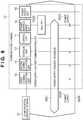
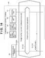
- the first communication unit 43 and the second communication unit 44 shown in Fig. 10will be described next with reference to Fig. 11 .
- MACs 50 and 60provide the same function as the MACs 20 and 30 (described with reference to Fig. 3 ).
- BBPs 51 and 61provide the same function as the BBPs 21 and 31.
- RFs 52 and 62provide the same function as the RFs 22 and 32.
- Antennas 53 and 63provide the same function as the antennas 23 and 33.
- the first communication unit 43 of the communication control terminal 40includes a power supply unit 54 which supplies power via the antenna 53. More specifically, the communication control terminal 40 supplies, using the power supply unit 54, power to the communication terminal 10 via its first communication unit 13. Note that the MAC 50 controls the power supply unit 54.
- the communication control terminal 40supplies power to the first communication unit 13 of the communication terminal 10 via the first communication unit 43.
- the communication control terminal 40is thus connected to the communication terminal 10 (S900).
- the communication control terminal 40exchanges a communication data amount with the communication terminal 10 via the second communication unit 44 (S901).
- the communication datacan be either uplink data or downlink data to or from the communication terminal 10.
- the communication control terminal 40causes the control unit 41 to determine whether a power supply request is received from the communication terminal 10. Note that the power supply request reception is done using the first communication unit 43. If a power supply request is received (YES in step S902), the communication control terminal 40 supplies power corresponding to the received necessary amount of electric power to the communication terminal 10 via the first communication unit 43 (S905).
- the control unit 41 of the communication control terminal 40performs data communication via the second communication unit 44 (S903). If the data communication has ended (YES in step S904), the control unit 41 determines whether a power supply stop is received from the communication terminal 10. If a power supply stop is received (YES in step S906), the communication control terminal 40 causes the control unit 41 to stop power supply via the first communication unit 43 (S908), and ends the processing. If no power supply stop is received (NO in step S906), the communication control terminal 40 causes the control unit 41 to determine whether power is being supplied. If power is being supplied (YES in step S907), the process returns to step S906. If no power is being supplied (NO in step S907), the processing ends.
- the communication control terminal 40causes the control unit 41 to issue a command to request activation of the first communication unit 43 (S1000).
- the MAC 50 of the first communication unit 43activates the power supply unit 54. This activates the first communication unit 43 of the communication control terminal 40 (S1001).
- the first communication unit 13 of the communication terminal 10Upon receiving power supplied from the first communication unit 43 of the communication control terminal 40 (S1002), the first communication unit 13 of the communication terminal 10 is activated (S1003). The first communication unit 13 of the communication terminal 10 returns, to the communication control terminal 40, a response representing that it is activated as a storage, thereby establishing connection to the communication control terminal 40 (S1004).
- the communication control terminal 40causes the control unit 41 to issue a command to request activation of the second communication unit 44 (S1005). This activates the second communication unit 44 of the communication control terminal 40 (S1006). The second communication unit 14 of the communication terminal 10 is also activated (S1007). Then, the communication control terminal 40 and the communication terminal 10 exchange a communication data amount (S1008).
- the communication terminal 10requests, via the first communication unit 13, power supply for data communication of the communication control terminal 40 (S1009).
- the communication control terminal 40starts power supply to the communication terminal 10 via the first communication unit 43.
- the communication control terminal 40starts data communication with the communication terminal 10 (S1010).
- the communication terminal 10requests the communication control terminal 40 to stop power supply (S1011).
- the communication terminal 10executes a power supply request sequence (S1100).
- the communication control terminal 40starts power supply to the communication terminal 10 via the first communication unit 43 (S1101).
- the communication terminal 10transmits a power supply request to the communication control terminal 40 (S1200).
- the communication control terminal 40causes the control unit 41 to receive the power supply request via the first communication unit 43.
- the communication terminal 10transmits a power supply request to the communication control terminal 40.
- the communication control terminal 40receives the power supply request via the first communication unit 43 (S1300).
- the communication control terminal 40causes the control unit 41 to request, of the communication terminal 10, a charge corresponding to the amount of electric power to be supplied (S1301).
- the communication control terminal 40causes the control unit 41 to receive the payment via the first communication unit 43 (S1302).
- the present inventioncan adopt embodiments in the forms of, for example, a system, apparatus, method, program, and storage medium.
- the present inventionmay be applied to either a system constituted by a plurality of devices, or an apparatus consisting of a single device.
- the present inventionincludes a case wherein the functions of the aforementioned embodiments are achieved when a software program is directly or remotely supplied to a system or apparatus, and a computer incorporated in that system or apparatus reads out and executes the supplied program codes.
- the program to be supplied in this caseis a computer program corresponding to the illustrated flowcharts in the embodiments.
- the program codes themselves installed in a computer to implement the functional processing of the present invention using the computeralso implement the present invention. That is, the present invention includes the computer program itself for implementing the functional processing of the present invention.
- the form of programis not particularly limited, and an object code, a program to be executed by an interpreter, script data to be supplied to an OS (Operating System), and the like may be used as long as they have the functions of the program.
- a computer-readable storage medium for supplying the computer programthe following media can be used.
- a floppy® disk, hard disk, optical disk, magneto-optical disk, MO, CD-ROM, CD-R, CD-RW, magnetic tape, nonvolatile memory card, ROM, and DVD (DVD-ROM, DVD-R)can be used.
- the userestablishes connection to a website on the Internet using a browser on a client computer, and downloads the computer program of the present invention from the website onto a recording medium such as a hard disk.
- the program to be downloadedmay be a compressed file including an automatic installation function.
- program codes that form the program of the present inventionmay be segmented into a plurality of files, which may be downloaded from different websites. That is, the present invention includes a WWW server, which makes a plurality of users download program files required to implement the functional processing of the present invention on their computers.
- a storage mediumsuch as a CD-ROM, which stores the encrypted program of the present invention, may be delivered to the user.
- the user who has cleared a predetermined conditionmay be allowed to download key information used to decrypt the encrypted program from a website via the Internet. The user executes the encrypted program using that key information to install the program in a computer.
- the functions of the aforementioned embodimentscan be implemented when the computer executes the readout program.
- the functions of the aforementioned embodimentsmay be implemented in collaboration with an OS or the like running on the computer based on an instruction of that program.
- the OS or the likeexecutes some or all of actual processes, which implement the functions of the aforementioned embodiments.
- some or all of the functions of the aforementioned embodimentsmay be implemented when the program read out from the recording medium is written in a memory equipped on a function expansion board or a function expansion unit, which is inserted into or connected to the computer.
- a CPU or the like equipped on the function expansion board or unitexecutes some or all of actual processes based on an instruction of that program.
Landscapes
- Engineering & Computer Science (AREA)
- Microelectronics & Electronic Packaging (AREA)
- Computer Hardware Design (AREA)
- Physics & Mathematics (AREA)
- General Physics & Mathematics (AREA)
- Theoretical Computer Science (AREA)
- Computer Networks & Wireless Communication (AREA)
- Computer Vision & Pattern Recognition (AREA)
- Health & Medical Sciences (AREA)
- Artificial Intelligence (AREA)
- Toxicology (AREA)
- General Health & Medical Sciences (AREA)
- Electromagnetism (AREA)
- Signal Processing (AREA)
- Telephone Function (AREA)
- Near-Field Transmission Systems (AREA)
Description
- The present invention relates to communication apparatuses, control methods of communication apparatuses, and related computer programs, which perform communication using electromagnetic induction.
- A communication terminal which performs communication using a non-contact communication method is known. Japanese Patent Laid-Open No.
2005-323264 - The technique described in Japanese Patent Laid-Open No.
2005-323264 - The document
US 5,905,372 A relates to an apparatus and a method for delivering power to a contactless portable data device. Therein, a terminal device powers a portable data device by transmitting in two modes of operation. In a first mode of operation, the terminal transmits to the portable data device a power signal at a first level and a data signal using a first modulation format and a first bit rate. In a second mode of operation, the terminal transmits to the portable data terminal a power signal at a second level and a data signal using a second modulation format and a second bit rate. The terminal determines a requirement to change modes of operation, and changes modes in response to changing power requirements of the portable data device. - The document
US 2007/072474 A1 relates to flexible power adapter systems and methods. Therein, a power adapter is provided that includes a base adapter configured to perform power conversion to supply power requirements of an electronic device from a power source. The power adapter converts the power signal from the power source into power signal compatible with the first electronic device. Input and output connectors provide coupling to the power source and electronic device, respectively. An accessory adapter can be provided and can be configured to be removably coupleable to the base adapter for modular operation. The accessory adapter can be configured to provide another power signal to power a second electronic device. Multiple accessory adapters can be added to provide power requirements for multiple devices. Security keys can be used to authenticate the power supply for security and verification purposes. - The present invention provides communication apparatuses, control methods of communication apparatuses, and related computer programs, which increase the reliability of data communication between communication terminals using power supplied by electromagnetic induction.
- According to a first aspect of the present invention, there is provided a communication apparatus, as defined in claims 1 to 7.
- According to a second aspect of the present invention, there is provided a control method of a communication apparatus, as defined in claim 8.
- According to a third aspect of the present invention, there is provided a computer program, as defined in claim 9.
- According to a fourth aspect of the present invention, there is provided a communication apparatus, as defined in
claim 10. - According to a fifth aspect of the present invention, there is provided a control method of a communication apparatus, as defined in
claim 15. - According to a sixth aspect of the present invention, there is provided a computer program, as defined in
claim 16. - Further features of the present invention will become apparent from the following description of exemplary embodiments with reference to the attached drawings.
Fig. 1 is a view showing an example of the arrangement of a communication system including a communication terminal according to an embodiment of the present invention;Fig. 2 is a block diagram showing an example of the arrangement of acommunication terminal 10 shown inFig. 1 ;Fig. 3 is a block diagram showing examples of the arrangements of afirst communication unit 13 and asecond communication unit 14 shown inFig. 2 ;Fig. 4 is a flowchart illustrating an example of the operation of thecommunication terminal 10 shown inFig. 1 ;Fig. 5 is a sequence chart showing an example of the sequence of processing of causing thecommunication terminal 10 shown inFig. 1 to perform data communication with acommunication control terminal 40;Fig. 6 is a sequence chart showing an example of the sequence of power supply processing in step S208 ofFig. 5 ;Fig. 7 is a sequence chart showing an example of processing of the power supply request sequence in step S301 ofFig. 6 ;Fig. 8 is a sequence chart showing an example of the sequence of power supply processing according to the second embodiment;Fig. 9 is a sequence chart showing an example of processing of the power supply request sequence according to the third embodiment;Fig. 10 is a block diagram showing an example of the arrangement of acommunication control terminal 40 according to the fourth embodiment;Fig. 11 is a block diagram showing examples of the arrangements of afirst communication unit 43 and asecond communication unit 44 shown inFig. 10 ;Fig. 12 is a flowchart illustrating an example of the operation of thecommunication control terminal 40 according to the fourth embodiment;Fig. 13 is a sequence chart showing an example of the sequence of processing of causing thecommunication control terminal 40 shown inFig. 10 to perform data communication with acommunication terminal 10;Fig. 14 is a sequence chart showing an example of the sequence of power supply processing in step S1009 ofFig. 13 ;Fig. 15 is a first sequence chart showing an example of processing of the power supply request sequence in step S1100 ofFig. 14 ; andFig. 16 is a second sequence chart showing an example of processing of the power supply request sequence in step S1100 ofFig. 14 .- Preferred embodiments of the present invention will now be described in detail with reference to the drawings. It should be noted that the relative arrangement of the components, the numerical expressions and numerical values set forth in these embodiments do not limit the scope of the present invention unless it is specifically stated otherwise.
Fig. 1 is a view showing an example of the arrangement of a communication system including a communication terminal according to an embodiment of the present invention.- A
communication control terminal 40 functions to control communication with acommunication terminal 10. Each of thecommunication control terminal 40 and thecommunication terminal 10 has a plurality (two in the embodiment) of communication (e.g., NFC (Near Field Communication) standard) interfaces and performs data communication using these interfaces. If circumstances require, thecommunication control terminal 40 supplies power to thecommunication terminal 10. This power supply is done using, for example, a non-contact communication interface having a power supply function by electromagnetic induction. Fig. 2 is a block diagram showing an example of the arrangement of thecommunication terminal 10 shown inFig. 1 .- The
communication terminal 10 includes acontrol unit 11,storage unit 12,first communication unit 13,second communication unit 14,power management unit 15, andpower supply unit 16. - The
control unit 11 includes, for example, a CPU (Central Processing Unit) and comprehensively controls the entire communication terminal 10 (e.g., controls communication). Thestorage unit 12 includes, for example, a memory and stores programs and data. Thefirst communication unit 13 is a communication (e.g., NFC (Near Field Communication) standard) interface including, for example, an RFID (Radio Frequency IDentification) reader/writer and having a power supply function by electromagnetic induction. Thesecond communication unit 14 is a communication interface which adopts a communication scheme different from that of thefirst communication unit 13. Note that thesecond communication unit 14 needs only be a communication interface having a communication capability higher than that of the first communication unit 13 (thesecond communication unit 14 enables at least one of mass data communication and high-speed data communication). For example, a communication scheme such as USB (Universal Serial Bus) is usable. - The
power management unit 15 monitors the remaining power and manages the power supply output. Thepower supply unit 16 supplies power to each block via thepower management unit 15. Thepower management unit 15 selectively supplies, to each block, power from thepower supply unit 16 or power supplied from another terminal (e.g., communication partner terminal) via thefirst communication unit 13. - An example of the arrangement of the
communication terminal 10 has been described above. Thecommunication terminal 10 is not limited to the above-described arrangement and may additionally include functions of, for example, a storage device, input device, and output device as needed. Thecommunication control terminal 40 also has the same arrangement as thecommunication terminal 10 described above, and a description thereof will be omitted in this embodiment. - The
first communication unit 13 and thesecond communication unit 14 shown inFig. 2 will be explained with reference toFig. 3 . - Each of MACs (Medium Access Controllers) 20 and 30 manages a medium access layer. Each of BBPs (Base Band Processors) 21 and 31 has a communication signal processing function such as error correction coding, decoding, and modulation/demodulation. Each of RF (Radio Frequency) blocks 22 and 32 processes a baseband signal in the carrier frequency band. Each of
antennas - The
first communication unit 13 operates using power supplied by electromagnetic induction from an external device (e.g., communication control terminal 40) or power supplied from itself(power supply unit 16). Electromagnetic induction is caused using theantenna 23. If thefirst communication unit 13 operates using only power supplied by electromagnetic induction, the transmission speed is expected to be lower. Hence, thefirst communication unit 13 may operate using even power supplied from itself as needed. Thefirst communication unit 13 includes apower switch 24 whose power supply output is managed by theMAC 20. In thefirst communication unit 13, a reverse current preventing circuit (not shown) manages reverse current prevention. This management is done by thepower switch 24 and a command received by theMAC 20. - An example of the operation of the
communication terminal 10 shown inFig. 1 will be described next with reference toFig. 4 . An example will be explained here in which thecommunication terminal 10 communicates with the communication control terminal 40 (communication partner terminal). - The
communication control terminal 40 supplies power by electromagnetic induction to activate thefirst communication unit 13 of thecommunication terminal 10. Thecommunication terminal 10 is connected to thecommunication control terminal 40 via the first communication unit 13 (S100). Thecommunication terminal 10 exchanges a communication data amount with thecommunication control terminal 40 connected via the first communication unit 13 (S101). The communication data amount exchange is performed using thesecond communication unit 14. Note that the communication data can be either uplink data or downlink data to or from thecommunication control terminal 40. - The
communication terminal 10 causes thecontrol unit 11 to notify thepower management unit 15 of the communication data amount. Upon receiving the communication data amount, thepower management unit 15 calculates and predicts, based on it, an amount of electric power necessary for communication (S102). Thepower management unit 15 defines the predicted amount of electric power as a predetermined value, and compares it with the remaining power of thepower supply unit 16. Thepower management unit 15 thus determines whether the remaining power of thepower supply unit 16 is sufficient (S103). - If the remaining power is sufficient (YES in step S103), the
control unit 11 performs data communication via the second communication unit 14 (S104). If the data communication has ended (YES in step S109), thecontrol unit 11 determines whether power from thecommunication control terminal 40 is being received via thefirst communication unit 13. If power is being received (YES in step S110), thecontrol unit 11 sends a power supply stop request. More specifically, thecontrol unit 11 notifies thecommunication control terminal 40 of power supply stop via the first communication unit 13 (S111). Then, the processing ends. If power is not being received (NO in step S110), the processing directly ends. - If it is determined in step S103 that the remaining power is not sufficient (NO in step S103), the
control unit 11 determines whether power from thecommunication control terminal 40 is already being received via thefirst communication unit 13. If power is already being received (YES in step S105), thecontrol unit 11 requests thecommunication control terminal 40 to supply more power (S107). If power is not being received (NO in step S105), thecontrol unit 11 sends a power supply request to thecommunication control terminal 40 via the first communication unit 13 (S106). Thecommunication terminal 10 receives power from thecommunication control terminal 40 via thefirst communication unit 13 in response to the request (S108). Then, thecommunication terminal 10 returns to the processing in step S103. - An example of the sequence of processing of causing the
communication terminal 10 shown inFig. 1 to perform data communication with thecommunication control terminal 40 will be described with reference toFig. 5 . - The
communication control terminal 40 activates the first communication unit of its own to communicate with thefirst communication unit 13 of the communication terminal 10 (S200). This supplies power by electromagnetic induction to thefirst communication unit 13 of the communication terminal 10 (S201). At this time, thefirst communication unit 13 of thecommunication terminal 10 is activated as a storage (S202). Thefirst communication unit 13 of thecommunication terminal 10 returns, to thecommunication control terminal 40, a response representing that it is activated as a storage, thereby establishing connection to the communication control terminal 40 (S203). - The
first communication unit 13 of thecommunication terminal 10 requests activation of thesecond communication unit 14, and notifies thecontrol unit 11 that thefirst communication unit 13 is activated as a storage (S204). Thesecond communication unit 14 of thecommunication terminal 10 is activated in response to the activation request (S205). Next, thecommunication control terminal 40 activates the second communication unit of its own (S206). Then, thecommunication terminal 10 and thecommunication control terminal 40 exchange a communication data amount (S207). - Assume that the
communication terminal 10 has no sufficient remaining power for data communication corresponding to the exchanged communication data amount. In this case, thecommunication terminal 10 causes thecontrol unit 11 to request thecommunication control terminal 40 to supply power for data communication. Power supply to thecommunication terminal 10 via thefirst communication unit 13 starts in response to the request (S208). Thecommunication terminal 10 starts data communication with thecommunication control terminal 40 using the power (S209). When the data communication has ended, thecommunication terminal 10 requests thecommunication control terminal 40 to stop power supply (S210). - An example of the sequence of power supply processing in step S208 of
Fig. 5 will be described next with reference toFig. 6 . - The
communication terminal 10 causes thepower management unit 15 to determine whether a voltage level Vps of thepower supply unit 16 is equal to or lower than a voltage level Vtf necessary for data communication (S300). If the voltage level Vps of thepower supply unit 16 is equal to or lower than Vtf, thecommunication terminal 10 executes a power supply request sequence (S301). In response to the request, thecommunication control terminal 40 supplies power to each block of thecommunication terminal 10 via the first communication unit 13 (S302). Note that thepower supply unit 16 never supplies power unless the voltage level exceeds Vtf (S303). This is controlled by the reverse current preventing circuit. - An example of processing of the power supply request sequence in step S301 of
Fig. 6 will be described next with reference toFig. 7 . - The
power management unit 15 notifies thecontrol unit 11 of the determination result in step S300. Upon receiving this, thecontrol unit 11 transmits a power supply request to thecommunication control terminal 40 via the first communication unit 13 (S400). - As described above, the
communication terminal 10 requests thecommunication control terminal 40 to supply power by electromagnetic induction based on the relationship between remaining power and power necessary for data communication. It is therefore possible to newly activate an application for data communication even when, for example, the remaining power is low. This also prevents, for example, any power shortage during execution of an application and an interrupt of processing. For these reasons, the reliability of data communication increases. - The second embodiment will be described next. In the second embodiment, externally supplied power is stored. A communication system and a communication terminal according to the second embodiment have the same arrangements as in
Figs. 1 ,2 , and3 described in the first embodiment, and a description thereof will not be repeated. The arrangement of apower supply unit 16 of acommunication terminal 10 is slightly different. Unlike the first embodiment, thepower supply unit 16 of the second embodiment has a power storage function as a secondary battery. - The operation of the
communication terminal 10 according to the second embodiment will be described. The operation of thecommunication terminal 10 according to the second embodiment is the same as inFigs. 4 and5 described in the first embodiment. Only a point different from the first embodiment will be explained here. The different point is the processing in step S208 ofFig. 5 described in the first embodiment. - An example of the sequence of power supply processing in step S208 (
Fig. 5 ) according to the second embodiment will be described with reference toFig. 8 . - The
communication terminal 10 causes apower management unit 15 to determine whether a voltage level Vps of thepower supply unit 16 is equal to or lower than a voltage level Vtf necessary for data communication (S500). If the voltage level Vps of thepower supply unit 16 is equal to or lower than Vtf, thecommunication terminal 10 executes a power supply request sequence (S501). In response to the request, acommunication control terminal 40 supplies power to each block of thecommunication terminal 10 via a first communication unit 13 (S502). At this time, the power supplied from thecommunication control terminal 40 is supplied to thepower supply unit 16 too. Thepower supply unit 16 stores the power (S503). - Assume that the voltage level Vps of the
power supply unit 16 which has stored the power exceeds the voltage level Vtf necessary for data communication. Thecontrol unit 11 of thecommunication terminal 10 notifies thecommunication control terminal 40 of power supply stop via the first communication unit 13 (S505). After that, thepower supply unit 16 starts supplying power to each block of the communication terminal 10 (S506). Thecommunication terminal 10 performs data communication via thesecond communication unit 14 using the supplied power. - The third embodiment will be described next. In the third embodiment, a charge(fee) for externally supplied power is paid. A communication system and a communication terminal according to the third embodiment have the same arrangements as in
Figs. 1 ,2 , and3 described in the first embodiment, and a description thereof will not be repeated. The third embodiment is different in that afirst communication unit 13 has an electronic settlement function. Apower supply unit 16 may have a power storage function as a secondary battery, as in the second embodiment. - The operation of a
communication terminal 10 according to the third embodiment will be described. The operation of thecommunication terminal 10 according to the third embodiment is the same as inFigs. 4 and5 described in the first embodiment. Only a point different from the first embodiment will be explained here. The different point is the power supply request sequence (S301 inFig. 6 ). - An example of processing of the power supply request sequence according to the third embodiment will be described with reference to
Fig. 9 . - A
power management unit 15 notifies acontrol unit 11 of the determination result in step S300. Upon receiving this, thecontrol unit 11 transmits a power supply request to acommunication control terminal 40 via the first communication unit 13 (S600). - The
communication control terminal 40 requests, of thecommunication terminal 10, a charge(fee) corresponding to the amount of electric power to be supplied (S601). Upon receiving the request, thecontrol unit 11 of thecommunication terminal 10 makes a settlement of the requested charge via the first communication unit 13 (S602). In this case, since the charge corresponding to the amount of electric power to be supplied needs to be paid, thecommunication terminal 10 holds account information corresponding to the amount already paid by the user. The charge request or charge settlement between thecommunication control terminal 40 and the communication terminal can employ conventional charging processing or settlement processing, and a detailed description thereof will be omitted. - The fourth embodiment will be described next. In the fourth embodiment, the arrangement and operation of a
communication control terminal 40 will be described. A communication system according to the fourth embodiment has the same arrangement as inFigs. 1 ,2 , and3 described in the first embodiment, and a description thereof will not be repeated. - An example of the arrangement of the
communication control terminal 40 according to the fourth embodiment will be described with reference toFig. 10 . - The
communication control terminal 40 includes acontrol unit 41,storage unit 42,first communication unit 43, andsecond communication unit 44. Thecommunication control terminal 40 also includes a power supply unit and the like, although a description thereof will be omitted. - The
control unit 41 provides the same function as acontrol unit 11 of acommunication terminal 10. Thestorage unit 42 provides the same function as astorage unit 12 of thecommunication terminal 10. Thefirst communication unit 43 provides the same function as afirst communication unit 13 of thecommunication terminal 10. Thesecond communication unit 44 provides the same function as asecond communication unit 14 of thecommunication terminal 10. - An example of the arrangement of the
communication control terminal 40 has been described above. Like the above-describedcommunication terminal 10, thecommunication control terminal 40 is not limited to the above-described arrangement and may additionally include functions of, for example, a storage device, input device, and output device as needed. - The
first communication unit 43 and thesecond communication unit 44 shown inFig. 10 will be described next with reference toFig. 11 . MACs MACs 20 and 30 (described with reference toFig. 3 ). BBPs 51 and 61 provide the same function as the BBPs 21 and 31.RFs RFs Antennas antennas - The
first communication unit 43 of thecommunication control terminal 40 includes apower supply unit 54 which supplies power via theantenna 53. More specifically, thecommunication control terminal 40 supplies, using thepower supply unit 54, power to thecommunication terminal 10 via itsfirst communication unit 13. Note that theMAC 50 controls thepower supply unit 54. - An example of the operation of the
communication control terminal 40 according to the fourth embodiment will be described next with reference toFig. 12 . - The
communication control terminal 40 supplies power to thefirst communication unit 13 of thecommunication terminal 10 via thefirst communication unit 43. Thecommunication control terminal 40 is thus connected to the communication terminal 10 (S900). Thecommunication control terminal 40 exchanges a communication data amount with thecommunication terminal 10 via the second communication unit 44 (S901). Note that the communication data can be either uplink data or downlink data to or from thecommunication terminal 10. - The
communication control terminal 40 causes thecontrol unit 41 to determine whether a power supply request is received from thecommunication terminal 10. Note that the power supply request reception is done using thefirst communication unit 43. If a power supply request is received (YES in step S902), thecommunication control terminal 40 supplies power corresponding to the received necessary amount of electric power to thecommunication terminal 10 via the first communication unit 43 (S905). - Then, the
control unit 41 of thecommunication control terminal 40 performs data communication via the second communication unit 44 (S903). If the data communication has ended (YES in step S904), thecontrol unit 41 determines whether a power supply stop is received from thecommunication terminal 10. If a power supply stop is received (YES in step S906), thecommunication control terminal 40 causes thecontrol unit 41 to stop power supply via the first communication unit 43 (S908), and ends the processing. If no power supply stop is received (NO in step S906), thecommunication control terminal 40 causes thecontrol unit 41 to determine whether power is being supplied. If power is being supplied (YES in step S907), the process returns to step S906. If no power is being supplied (NO in step S907), the processing ends. - An example of the sequence of processing of causing the
communication control terminal 40 shown inFig. 10 to perform data communication with thecommunication terminal 10 will be described with reference toFig. 13 . - The
communication control terminal 40 causes thecontrol unit 41 to issue a command to request activation of the first communication unit 43 (S1000). Upon receiving the command, theMAC 50 of thefirst communication unit 43 activates thepower supply unit 54. This activates thefirst communication unit 43 of the communication control terminal 40 (S1001). - Upon receiving power supplied from the
first communication unit 43 of the communication control terminal 40 (S1002), thefirst communication unit 13 of thecommunication terminal 10 is activated (S1003). Thefirst communication unit 13 of thecommunication terminal 10 returns, to thecommunication control terminal 40, a response representing that it is activated as a storage, thereby establishing connection to the communication control terminal 40 (S1004). - The
communication control terminal 40 causes thecontrol unit 41 to issue a command to request activation of the second communication unit 44 (S1005). This activates thesecond communication unit 44 of the communication control terminal 40 (S1006). Thesecond communication unit 14 of thecommunication terminal 10 is also activated (S1007). Then, thecommunication control terminal 40 and thecommunication terminal 10 exchange a communication data amount (S1008). - Assume that the
communication terminal 10 has no sufficient remaining power for data communication corresponding to the exchanged communication data amount. In this case, thecommunication terminal 10 requests, via thefirst communication unit 13, power supply for data communication of the communication control terminal 40 (S1009). In response to the request, thecommunication control terminal 40 starts power supply to thecommunication terminal 10 via thefirst communication unit 43. - The
communication control terminal 40 starts data communication with the communication terminal 10 (S1010). When the data communication has ended, thecommunication terminal 10 requests thecommunication control terminal 40 to stop power supply (S1011). - An example of the sequence of power supply processing in step S1009 of
Fig. 13 will be described next with reference toFig. 14 . - The
communication terminal 10 executes a power supply request sequence (S1100). In response to the request, thecommunication control terminal 40 starts power supply to thecommunication terminal 10 via the first communication unit 43 (S1101). - An example of processing of the power supply request sequence in step S1100 of
Fig. 14 will be described next with reference toFig. 15 . - The
communication terminal 10 transmits a power supply request to the communication control terminal 40 (S1200). Thecommunication control terminal 40 causes thecontrol unit 41 to receive the power supply request via thefirst communication unit 43. - An example of processing of the power supply request sequence when requesting payment of a charge for power to be supplied, as in the second embodiment, will be described with reference to
Fig. 16 . - The
communication terminal 10 transmits a power supply request to thecommunication control terminal 40. Thecommunication control terminal 40 receives the power supply request via the first communication unit 43 (S1300). Thecommunication control terminal 40 causes thecontrol unit 41 to request, of thecommunication terminal 10, a charge corresponding to the amount of electric power to be supplied (S1301). When thecommunication terminal 10 has made a settlement of the charge, thecommunication control terminal 40 causes thecontrol unit 41 to receive the payment via the first communication unit 43 (S1302). - Typical embodiments of the present invention have been described above. However, the present invention is not limited to the aforementioned and illustrated embodiments, and can be properly modified without departing from the scope of the invention.
- The present invention can adopt embodiments in the forms of, for example, a system, apparatus, method, program, and storage medium. The present invention may be applied to either a system constituted by a plurality of devices, or an apparatus consisting of a single device.
- The present invention includes a case wherein the functions of the aforementioned embodiments are achieved when a software program is directly or remotely supplied to a system or apparatus, and a computer incorporated in that system or apparatus reads out and executes the supplied program codes. The program to be supplied in this case is a computer program corresponding to the illustrated flowcharts in the embodiments.
- Therefore, the program codes themselves installed in a computer to implement the functional processing of the present invention using the computer also implement the present invention. That is, the present invention includes the computer program itself for implementing the functional processing of the present invention. In this case, the form of program is not particularly limited, and an object code, a program to be executed by an interpreter, script data to be supplied to an OS (Operating System), and the like may be used as long as they have the functions of the program.
- As a computer-readable storage medium for supplying the computer program, the following media can be used. For example, a floppy® disk, hard disk, optical disk, magneto-optical disk, MO, CD-ROM, CD-R, CD-RW, magnetic tape, nonvolatile memory card, ROM, and DVD (DVD-ROM, DVD-R) can be used.
- As another program supply method, the user establishes connection to a website on the Internet using a browser on a client computer, and downloads the computer program of the present invention from the website onto a recording medium such as a hard disk. In this case, the program to be downloaded may be a compressed file including an automatic installation function. Also, program codes that form the program of the present invention may be segmented into a plurality of files, which may be downloaded from different websites. That is, the present invention includes a WWW server, which makes a plurality of users download program files required to implement the functional processing of the present invention on their computers.
- Also, a storage medium such as a CD-ROM, which stores the encrypted program of the present invention, may be delivered to the user. In this case, the user who has cleared a predetermined condition may be allowed to download key information used to decrypt the encrypted program from a website via the Internet. The user executes the encrypted program using that key information to install the program in a computer.
- The functions of the aforementioned embodiments can be implemented when the computer executes the readout program. In addition, the functions of the aforementioned embodiments may be implemented in collaboration with an OS or the like running on the computer based on an instruction of that program. In this case, the OS or the like executes some or all of actual processes, which implement the functions of the aforementioned embodiments.
- Furthermore, some or all of the functions of the aforementioned embodiments may be implemented when the program read out from the recording medium is written in a memory equipped on a function expansion board or a function expansion unit, which is inserted into or connected to the computer. In this case, after the program is written in the function expansion board or unit, a CPU or the like equipped on the function expansion board or unit executes some or all of actual processes based on an instruction of that program.
- According to the present invention, it is possible to increase the reliability of data communication between communication terminals using power supplied by electromagnetic induction.
- While the present invention has been described with reference to exemplary embodiments, it is to be understood that the invention is not limited to the disclosed exemplary embodiments. The scope of the following claims is to be accorded the broadest interpretation so as to encompass all such modifications and equivalent structures and functions.
Claims (16)
- A communication apparatus (10), comprising:power receiving means (13) for receiving electrical power wirelessly supplied from another communication apparatus;first communication means for performing, in response to a first power receiving operation, in which power is received from said another communication apparatus, by the power receiving means, communication for requesting a supply of electrical power via a second power receiving operation, in which power is received from said another communication apparatus, using electrical power received via the first power receiving operation;second communication means for performing wireless communication, wherein the second communication means differs from the first communication means; andcontrol means (15) for controlling the second communication means to operate using electrical power received via the second power receiving operation by the power receiving means.
- The communication apparatus according to claim 1, wherein
the first communication means is adapted to perform communication for stopping a supply of electrical power from said another communication apparatus in a case where the second power receiving operation is being performed, and/or
the first communication means is adapted to perform communication for settling a charge corresponding to an amount of electric power to be supplied from said another communication apparatus, and/or
the first communication means is adapted to perform communication for transmitting an ID associated with the communication apparatus. - The communication apparatus according to claim 1 or 2, wherein
a communication rate of the second communication means is higher than that of the first communication means, and/or
the second power receiving operation is performed during communication by the second communication means. - The communication apparatus according to any of claims 1 to 3, further comprising power storage means for storing electrical power received via the second power receiving operation.
- The communication apparatus according to any of claims 1 to 4, wherein
the power receiving means is adapted to receive electrical power based on an electro-magnetic field generated by said another communication apparatus, and/or
the first communication means is adapted to perform communication based on an electro-magnetic field generated by said another communication apparatus, and/or
the first communication means is adapted to perform communication by "Near Field Communication", and/or
the control means is adapted to control the communication apparatus such that the communication apparatus operates without the power receiving means receiving electrical power, in a case where a predetermined condition is satisfied. - The communication apparatus according to claim 4, wherein the power storage means does not store electrical power received via the first power receiving operation but stores electrical power received via the second power receiving operation.
- The communication apparatus according to any of claims 1 to 6, wherein
the power receiving means is adapted to perform the second power receiving operation in response to the communication for requesting a supply of electrical power via the second power receiving operation, and/or
the first communication means is adapted to be activated in response to the first power receiving operation. - A control method of a communication apparatus (10), which comprises power receiving means (13) for receiving electrical power wirelessly supplied from another communication apparatus, first communication means, and second communication means differing from the first communication means, the method comprising:performing, by the first communication means, in response to a first power receiving operation, in which power is received from said another communication apparatus, by the power receiving means, communication for requesting a supply of electrical power via a second power receiving operation, in which power is received from said another communication apparatus, using electrical power received via the first power receiving operation;controlling the second communication means to operate using electrical power received via the second power receiving operation by the power receiving means; andperforming wireless communication by the second communication means.
- A computer program for causing a communication apparatus (10), which comprises power receiving means (13) for receiving electrical power wirelessly supplied from another communication apparatus, first communication means, and second communication means differing from the first communication means, to execute the control method according to claim 8.
- A communication apparatus (40), comprising:power transmitting means (43) for wirelessly transmitting electrical power to another communication apparatus;first communication means (44) for performing, in response to a first power transmitting operation, in which power is transmitted to said another communication apparatus, by the power transmitting means, communication for accepting a request for a supply of electrical power via a second power transmitting operation, in which power is transmitted to said another communication apparatus, by the power transmitting means; andsecond communication means for performing wireless communication, wherein the second communication means differs from the first communication means,wherein the power transmitting means is adapted to perform the second power transmitting operation in response to the communication for accepting a request for a supply of electrical power via the second power transmitting operation,wherein the second communication means is adapted to communicate wirelessly with said another communication apparatus which is operated by using power supplied from the second power transmitting operation.
- The communication apparatus according to claim 10, wherein
the power transmitting means is adapted to stop the second power transmitting operation in a case where the second power transmitting operation is being performed and the first communication means receives a request for stopping the second power transmitting operation from said another communication apparatus, and/or
the first communication means is adapted to perform communication for settling a charge corresponding to an amount of electric power to be supplied to said another communication apparatus, and/or
the first communication means is adapted to perform communication for receiving an ID associated with said another communication apparatus, and/or
the communication for accepting a request for a supply of electrical power via the second power transmitting operation is started in response to said another communication apparatus receiving electrical power, which is transmitted via the first power transmitting operation. - The communication apparatus according to claim 10 or 11, wherein the first power transmitting operation is a power transmitting operation for causing a first communication unit in said another communication apparatus to be activated.
- The communication apparatus according to claim 12, wherein the second power transmitting operation is a power transmitting operation for causing a second communication unit in said another communication apparatus, which differs from the first communication unit, to operate.
- The communication apparatus according to any of claims 10 to 13, wherein
the second power transmitting operation is a power transmitting operation for causing said another communication apparatus to store electrical power, and/or
the power transmitting means is adapted to transmit electrical power by generating an electro-magnetic field, and/or
the first communication means is adapted to perform communication by "Near Field Communication". - A control method of a communication apparatus (40), which comprises power transmitting means (43) for wirelessly transmitting electrical power to another communication apparatus, first communication means, and second communication means differing from the first communication means, the method comprising:performing, by the first communication means, in response to a first power transmitting operation, in which power is transmitted to said another communication apparatus, by the power transmitting means, communication for accepting a request for a supply of electrical power via a second power transmitting operation in which power is transmitted to said another communication apparatus by the power transmitting means;performing the second power transmitting operation in response to the communication for accepting a request for a supply of electrical power via the second power transmitting operation; andperforming, by the second communication means, wireless communication with said another communication apparatus which is operated by using power supplied from the second power transmitting operation.
- A computer program for causing a communication apparatus (40), which comprises power transmitting means (43) for wirelessly transmitting electrical power to another communication apparatus, first communication means, and second communication means differing from the first communication means, to execute the control method according to claim 15.
Priority Applications (1)
| Application Number | Priority Date | Filing Date | Title |
|---|---|---|---|
| EP17188952.0AEP3285195B1 (en) | 2008-04-03 | 2009-03-25 | Communication apparatus, computer program, and communication method |
Applications Claiming Priority (2)
| Application Number | Priority Date | Filing Date | Title |
|---|---|---|---|
| JP2008097481AJP5159396B2 (en) | 2008-04-03 | 2008-04-03 | Communication device, control method thereof, and program |
| EP09727584.6AEP2263322B1 (en) | 2008-04-03 | 2009-03-25 | Communication terminal, computer-readable storage medium, and communication method |
Related Parent Applications (2)
| Application Number | Title | Priority Date | Filing Date |
|---|---|---|---|
| EP09727584.6ADivisionEP2263322B1 (en) | 2008-04-03 | 2009-03-25 | Communication terminal, computer-readable storage medium, and communication method |
| EP09727584.6ADivision-IntoEP2263322B1 (en) | 2008-04-03 | 2009-03-25 | Communication terminal, computer-readable storage medium, and communication method |
Related Child Applications (2)
| Application Number | Title | Priority Date | Filing Date |
|---|---|---|---|
| EP17188952.0ADivisionEP3285195B1 (en) | 2008-04-03 | 2009-03-25 | Communication apparatus, computer program, and communication method |
| EP17188952.0ADivision-IntoEP3285195B1 (en) | 2008-04-03 | 2009-03-25 | Communication apparatus, computer program, and communication method |
Publications (2)
| Publication Number | Publication Date |
|---|---|
| EP2784718A1 EP2784718A1 (en) | 2014-10-01 |
| EP2784718B1true EP2784718B1 (en) | 2017-11-01 |
Family
ID=41135616
Family Applications (3)
| Application Number | Title | Priority Date | Filing Date |
|---|---|---|---|
| EP14167292.3AActiveEP2784718B1 (en) | 2008-04-03 | 2009-03-25 | Communication apparatus, computer-readable storage medium, and communication method |
| EP17188952.0AActiveEP3285195B1 (en) | 2008-04-03 | 2009-03-25 | Communication apparatus, computer program, and communication method |
| EP09727584.6AActiveEP2263322B1 (en) | 2008-04-03 | 2009-03-25 | Communication terminal, computer-readable storage medium, and communication method |
Family Applications After (2)
| Application Number | Title | Priority Date | Filing Date |
|---|---|---|---|
| EP17188952.0AActiveEP3285195B1 (en) | 2008-04-03 | 2009-03-25 | Communication apparatus, computer program, and communication method |
| EP09727584.6AActiveEP2263322B1 (en) | 2008-04-03 | 2009-03-25 | Communication terminal, computer-readable storage medium, and communication method |
Country Status (4)
| Country | Link |
|---|---|
| US (2) | US8676395B2 (en) |
| EP (3) | EP2784718B1 (en) |
| JP (1) | JP5159396B2 (en) |
| WO (1) | WO2009123249A1 (en) |
Families Citing this family (6)
| Publication number | Priority date | Publication date | Assignee | Title |
|---|---|---|---|---|
| JP5197112B2 (en) | 2008-04-04 | 2013-05-15 | キヤノン株式会社 | Communication device, control method thereof, and program |
| KR101795827B1 (en)* | 2010-06-04 | 2017-11-08 | 액세스 비지니스 그룹 인터내셔날 엘엘씨 | Wirelessly powered dielectric barrier discharge lamp, and base station for a wirelessly powered fluid treatment system |
| JP5843583B2 (en) | 2011-11-28 | 2016-01-13 | 株式会社東芝 | Wireless communication device, power transmission device, and IC card device |
| JP5801268B2 (en)* | 2012-09-03 | 2015-10-28 | 株式会社東芝 | Power transmission device, power reception device, and wireless power transmission system |
| JP6230324B2 (en)* | 2013-08-05 | 2017-11-15 | キヤノン株式会社 | Power receiving device, power receiving device control method and program |
| JP6399681B2 (en)* | 2013-09-03 | 2018-10-03 | 株式会社東芝 | Communication apparatus, processing method, and program |
Family Cites Families (42)
| Publication number | Priority date | Publication date | Assignee | Title |
|---|---|---|---|---|
| US5631536A (en)* | 1994-05-16 | 1997-05-20 | Tseng; Ling-Yuan | Rechargeable battery vending apparatus |
| US6233343B1 (en)* | 1997-09-26 | 2001-05-15 | Hewlett-Packard Company | Power adapter having a speaker for an electronic device |
| US5905372A (en)* | 1997-12-17 | 1999-05-18 | Motorola, Inc. | Apparatus and method for delivering power to a contactless portable data device |
| KR20010006519A (en)* | 1998-02-19 | 2001-01-26 | 비센트 비.인그라시아 | Data communications terminal and method of adjusting a power signal generated therefrom |
| JP2000090221A (en)* | 1998-09-09 | 2000-03-31 | Hitachi Maxell Ltd | Non-contact ic card |
| JP2000123135A (en)* | 1998-10-15 | 2000-04-28 | Sharp Corp | Information card with display |
| US7518267B2 (en)* | 2003-02-04 | 2009-04-14 | Access Business Group International Llc | Power adapter for a remote device |
| JP4089100B2 (en)* | 1999-08-20 | 2008-05-21 | 株式会社デンソー | Mobile phone connection device |
| US6184651B1 (en)* | 2000-03-20 | 2001-02-06 | Motorola, Inc. | Contactless battery charger with wireless control link |
| KR100671755B1 (en)* | 2001-04-25 | 2007-01-22 | 엘지전자 주식회사 | Power Control Method Using Universal Serial Bus |
| US7236742B2 (en)* | 2001-06-18 | 2007-06-26 | Brigham Young University | System and method for wireless data transfer for a mobile unit |
| JP3558059B2 (en)* | 2001-08-10 | 2004-08-25 | セイコーエプソン株式会社 | Power supply control circuit and electronic equipment |
| US6820206B1 (en)* | 2001-11-20 | 2004-11-16 | Palmone, Inc. | Power sharing between portable computer system and peripheral device |
| US6892052B2 (en)* | 2002-03-26 | 2005-05-10 | Nokia Corporation | Radio frequency identification (RF-ID) based discovery for short range radio communication |
| US7565108B2 (en)* | 2002-03-26 | 2009-07-21 | Nokia Corporation | Radio frequency identification (RF-ID) based discovery for short range radio communication with reader device having transponder functionality |
| JP3928853B2 (en)* | 2002-04-18 | 2007-06-13 | 大日本印刷株式会社 | Non-contact IC card |
| WO2003091943A1 (en) | 2002-04-24 | 2003-11-06 | Marconi Intellectual Property (Us) Inc | Energy source recharging device and method |
| US6756765B2 (en)* | 2002-10-08 | 2004-06-29 | Koninklijke Philips Electronics N.V. | System and method for charging users to recharge power supplies in portable devices |
| US7127621B2 (en)* | 2002-12-21 | 2006-10-24 | Emc Corporation | Peer power control |
| TWI347523B (en)* | 2003-02-05 | 2011-08-21 | Panasonic Corp | Peripheral device and control method thereof, and main device and control method thereof, and program thereof |
| US7752471B1 (en)* | 2003-09-17 | 2010-07-06 | Cypress Semiconductor Corporation | Adaptive USB mass storage devices that reduce power consumption |
| JP4513413B2 (en) | 2004-05-11 | 2010-07-28 | ソニー株式会社 | Wireless communication system, wireless communication apparatus, wireless communication method, and computer program |
| US7363520B1 (en)* | 2005-03-29 | 2008-04-22 | Emc Corporation | Techniques for providing power to a set of powerable devices |
| US20060223500A1 (en)* | 2005-03-31 | 2006-10-05 | Sanyo Electric Co., Ltd. | Authentication system |
| JP2006306379A (en)* | 2005-03-31 | 2006-11-09 | Sanyo Electric Co Ltd | Authenticating system, base station, and portable unit |
| GB0507285D0 (en)* | 2005-04-11 | 2005-05-18 | Innovision Res & Tech Plc | Nfc enabled high-speed data |
| US20070072474A1 (en)* | 2005-04-27 | 2007-03-29 | Nigel Beasley | Flexible power adapter systems and methods |
| US8244179B2 (en)* | 2005-05-12 | 2012-08-14 | Robin Dua | Wireless inter-device data processing configured through inter-device transmitted data |
| JP2006323683A (en)* | 2005-05-19 | 2006-11-30 | Canon Inc | Card device and control method thereof |
| US7471200B2 (en)* | 2005-06-30 | 2008-12-30 | Nokia Corporation | RFID optimized capability negotiation |
| JP2007143116A (en)* | 2005-10-19 | 2007-06-07 | Seiko Epson Corp | Wireless communication device |
| KR101232557B1 (en)* | 2006-09-28 | 2013-02-12 | 교세라 가부시키가이샤 | Mobile radio device |
| EP2086085B1 (en)* | 2006-11-08 | 2015-04-15 | Panasonic Corporation | Non-contact charger and non-contact charge system |
| JP2008165533A (en)* | 2006-12-28 | 2008-07-17 | Seiko Epson Corp | USB device, control method thereof, and program thereof |
| EP1986303A1 (en)* | 2007-04-25 | 2008-10-29 | Sony France S.A. | Peer-to-peer transaction-based power supply methods and systems |
| JP2008293173A (en)* | 2007-05-23 | 2008-12-04 | Nec Corp | Portable electronic equipment, data processor, data communication system, computer program, and data processing method |
| JP4940054B2 (en) | 2007-08-16 | 2012-05-30 | キヤノン株式会社 | Wireless communication system, wireless communication apparatus, and control method thereof |
| US8112641B2 (en)* | 2007-12-26 | 2012-02-07 | Cisco Technology, Inc. | Facilitating communication and power transfer between electrically-isolated powered device subsystems |
| US8093749B1 (en)* | 2008-01-29 | 2012-01-10 | Juniper Networks, Inc. | Sharing redundant power supply modules among physical systems |
| US8069100B2 (en)* | 2009-01-06 | 2011-11-29 | Access Business Group International Llc | Metered delivery of wireless power |
| JP2011205850A (en)* | 2010-03-26 | 2011-10-13 | Panasonic Electric Works Co Ltd | Noncontact power-receiving apparatus and noncontact charging system |
| US20120290470A1 (en)* | 2011-05-11 | 2012-11-15 | Samsung Electro-Mechanics Company, Ltd. | Payment systems and methods for providing wireless power transfer |
- 2008
- 2008-04-03JPJP2008097481Apatent/JP5159396B2/ennot_activeExpired - Fee Related
- 2009
- 2009-03-25USUS12/866,889patent/US8676395B2/enactiveActive
- 2009-03-25EPEP14167292.3Apatent/EP2784718B1/enactiveActive
- 2009-03-25EPEP17188952.0Apatent/EP3285195B1/enactiveActive
- 2009-03-25EPEP09727584.6Apatent/EP2263322B1/enactiveActive
- 2009-03-25WOPCT/JP2009/056772patent/WO2009123249A1/enactiveApplication Filing
- 2013
- 2013-02-25USUS13/776,626patent/US20130178157A1/ennot_activeAbandoned
Non-Patent Citations (1)
| Title |
|---|
| None* |
Also Published As
| Publication number | Publication date |
|---|---|
| EP2784718A1 (en) | 2014-10-01 |
| US20110035608A1 (en) | 2011-02-10 |
| EP2263322A1 (en) | 2010-12-22 |
| US20130178157A1 (en) | 2013-07-11 |
| EP2263322B1 (en) | 2014-06-18 |
| JP2009253551A (en) | 2009-10-29 |
| JP5159396B2 (en) | 2013-03-06 |
| EP3285195B1 (en) | 2019-07-10 |
| EP3285195A1 (en) | 2018-02-21 |
| WO2009123249A1 (en) | 2009-10-08 |
| EP2263322A4 (en) | 2012-01-11 |
| US8676395B2 (en) | 2014-03-18 |
Similar Documents
| Publication | Publication Date | Title |
|---|---|---|
| JP5376895B2 (en) | Charging apparatus, charging method and program | |
| EP2784718B1 (en) | Communication apparatus, computer-readable storage medium, and communication method | |
| CN102511129B (en) | Near field wireless communication device and its control method | |
| CN102201843B (en) | Communication device, communication method and communication system | |
| JP4766662B2 (en) | Management system and control method | |
| CN103001671B (en) | Systems and methods for providing nfc secure application support in battery-off mode when no nonvolatile memory write access is available | |
| US20150091496A1 (en) | Bi-directional communication with a device under charge | |
| JP2009190261A (en) | Printing device management system, printing device management method, and printing device management program | |
| JP2015032911A (en) | Control device, control method, and program | |
| US10123369B2 (en) | Communication terminal, computer-readable storage medium, and communication method | |
| US10411523B2 (en) | Intelligent multi-mode wireless power system | |
| JP5344656B2 (en) | Communication terminal, communication control terminal, program, and communication method | |
| JP6008908B2 (en) | COMMUNICATION DEVICE, ITS CONTROL METHOD, AND PROGRAM | |
| JP5584805B2 (en) | COMMUNICATION DEVICE, ITS CONTROL METHOD, AND PROGRAM | |
| JP7153042B2 (en) | Information processing device, information processing program and information processing system | |
| JP5462963B2 (en) | COMMUNICATION DEVICE, COMMUNICATION DEVICE CONTROL METHOD, AND PROGRAM | |
| CN111245478A (en) | Circuit control method, device, equipment and storage medium |
Legal Events
| Date | Code | Title | Description |
|---|---|---|---|
| 17P | Request for examination filed | Effective date:20140507 | |
| AC | Divisional application: reference to earlier application | Ref document number:2263322 Country of ref document:EP Kind code of ref document:P | |
| AK | Designated contracting states | Kind code of ref document:A1 Designated state(s):AT BE BG CH CY CZ DE DK EE ES FI FR GB GR HR HU IE IS IT LI LT LU LV MC MK MT NL NO PL PT RO SE SI SK TR | |
| PUAI | Public reference made under article 153(3) epc to a published international application that has entered the european phase | Free format text:ORIGINAL CODE: 0009012 | |
| R17P | Request for examination filed (corrected) | Effective date:20150401 | |
| RBV | Designated contracting states (corrected) | Designated state(s):AT BE BG CH CY CZ DE DK EE ES FI FR GB GR HR HU IE IS IT LI LT LU LV MC MK MT NL NO PL PT RO SE SI SK TR | |
| GRAP | Despatch of communication of intention to grant a patent | Free format text:ORIGINAL CODE: EPIDOSNIGR1 | |
| INTG | Intention to grant announced | Effective date:20170518 | |
| RIN1 | Information on inventor provided before grant (corrected) | Inventor name:AOKI, NORIHITO | |
| GRAS | Grant fee paid | Free format text:ORIGINAL CODE: EPIDOSNIGR3 | |
| GRAA | (expected) grant | Free format text:ORIGINAL CODE: 0009210 | |
| AC | Divisional application: reference to earlier application | Ref document number:2263322 Country of ref document:EP Kind code of ref document:P | |
| AK | Designated contracting states | Kind code of ref document:B1 Designated state(s):AT BE BG CH CY CZ DE DK EE ES FI FR GB GR HR HU IE IS IT LI LT LU LV MC MK MT NL NO PL PT RO SE SI SK TR | |
| REG | Reference to a national code | Ref country code:GB Ref legal event code:FG4D | |
| REG | Reference to a national code | Ref country code:CH Ref legal event code:EP Ref country code:AT Ref legal event code:REF Ref document number:942708 Country of ref document:AT Kind code of ref document:T Effective date:20171115 | |
| REG | Reference to a national code | Ref country code:IE Ref legal event code:FG4D | |
| REG | Reference to a national code | Ref country code:DE Ref legal event code:R096 Ref document number:602009049204 Country of ref document:DE | |
| REG | Reference to a national code | Ref country code:NL Ref legal event code:MP Effective date:20171101 | |
| REG | Reference to a national code | Ref country code:LT Ref legal event code:MG4D | |
| REG | Reference to a national code | Ref country code:FR Ref legal event code:PLFP Year of fee payment:10 | |
| REG | Reference to a national code | Ref country code:AT Ref legal event code:MK05 Ref document number:942708 Country of ref document:AT Kind code of ref document:T Effective date:20171101 | |
| PG25 | Lapsed in a contracting state [announced via postgrant information from national office to epo] | Ref country code:FI Free format text:LAPSE BECAUSE OF FAILURE TO SUBMIT A TRANSLATION OF THE DESCRIPTION OR TO PAY THE FEE WITHIN THE PRESCRIBED TIME-LIMIT Effective date:20171101 Ref country code:LT Free format text:LAPSE BECAUSE OF FAILURE TO SUBMIT A TRANSLATION OF THE DESCRIPTION OR TO PAY THE FEE WITHIN THE PRESCRIBED TIME-LIMIT Effective date:20171101 Ref country code:NL Free format text:LAPSE BECAUSE OF FAILURE TO SUBMIT A TRANSLATION OF THE DESCRIPTION OR TO PAY THE FEE WITHIN THE PRESCRIBED TIME-LIMIT Effective date:20171101 Ref country code:SE Free format text:LAPSE BECAUSE OF FAILURE TO SUBMIT A TRANSLATION OF THE DESCRIPTION OR TO PAY THE FEE WITHIN THE PRESCRIBED TIME-LIMIT Effective date:20171101 Ref country code:ES Free format text:LAPSE BECAUSE OF FAILURE TO SUBMIT A TRANSLATION OF THE DESCRIPTION OR TO PAY THE FEE WITHIN THE PRESCRIBED TIME-LIMIT Effective date:20171101 Ref country code:NO Free format text:LAPSE BECAUSE OF FAILURE TO SUBMIT A TRANSLATION OF THE DESCRIPTION OR TO PAY THE FEE WITHIN THE PRESCRIBED TIME-LIMIT Effective date:20180201 | |
| PG25 | Lapsed in a contracting state [announced via postgrant information from national office to epo] | Ref country code:IS Free format text:LAPSE BECAUSE OF FAILURE TO SUBMIT A TRANSLATION OF THE DESCRIPTION OR TO PAY THE FEE WITHIN THE PRESCRIBED TIME-LIMIT Effective date:20180301 Ref country code:HR Free format text:LAPSE BECAUSE OF FAILURE TO SUBMIT A TRANSLATION OF THE DESCRIPTION OR TO PAY THE FEE WITHIN THE PRESCRIBED TIME-LIMIT Effective date:20171101 Ref country code:BG Free format text:LAPSE BECAUSE OF FAILURE TO SUBMIT A TRANSLATION OF THE DESCRIPTION OR TO PAY THE FEE WITHIN THE PRESCRIBED TIME-LIMIT Effective date:20180201 Ref country code:LV Free format text:LAPSE BECAUSE OF FAILURE TO SUBMIT A TRANSLATION OF THE DESCRIPTION OR TO PAY THE FEE WITHIN THE PRESCRIBED TIME-LIMIT Effective date:20171101 Ref country code:AT Free format text:LAPSE BECAUSE OF FAILURE TO SUBMIT A TRANSLATION OF THE DESCRIPTION OR TO PAY THE FEE WITHIN THE PRESCRIBED TIME-LIMIT Effective date:20171101 Ref country code:GR Free format text:LAPSE BECAUSE OF FAILURE TO SUBMIT A TRANSLATION OF THE DESCRIPTION OR TO PAY THE FEE WITHIN THE PRESCRIBED TIME-LIMIT Effective date:20180202 | |
| PG25 | Lapsed in a contracting state [announced via postgrant information from national office to epo] | Ref country code:CZ Free format text:LAPSE BECAUSE OF FAILURE TO SUBMIT A TRANSLATION OF THE DESCRIPTION OR TO PAY THE FEE WITHIN THE PRESCRIBED TIME-LIMIT Effective date:20171101 Ref country code:SK Free format text:LAPSE BECAUSE OF FAILURE TO SUBMIT A TRANSLATION OF THE DESCRIPTION OR TO PAY THE FEE WITHIN THE PRESCRIBED TIME-LIMIT Effective date:20171101 Ref country code:CY Free format text:LAPSE BECAUSE OF FAILURE TO SUBMIT A TRANSLATION OF THE DESCRIPTION OR TO PAY THE FEE WITHIN THE PRESCRIBED TIME-LIMIT Effective date:20171101 Ref country code:EE Free format text:LAPSE BECAUSE OF FAILURE TO SUBMIT A TRANSLATION OF THE DESCRIPTION OR TO PAY THE FEE WITHIN THE PRESCRIBED TIME-LIMIT Effective date:20171101 Ref country code:DK Free format text:LAPSE BECAUSE OF FAILURE TO SUBMIT A TRANSLATION OF THE DESCRIPTION OR TO PAY THE FEE WITHIN THE PRESCRIBED TIME-LIMIT Effective date:20171101 | |
| REG | Reference to a national code | Ref country code:DE Ref legal event code:R097 Ref document number:602009049204 Country of ref document:DE | |
| PG25 | Lapsed in a contracting state [announced via postgrant information from national office to epo] | Ref country code:RO Free format text:LAPSE BECAUSE OF FAILURE TO SUBMIT A TRANSLATION OF THE DESCRIPTION OR TO PAY THE FEE WITHIN THE PRESCRIBED TIME-LIMIT Effective date:20171101 Ref country code:PL Free format text:LAPSE BECAUSE OF FAILURE TO SUBMIT A TRANSLATION OF THE DESCRIPTION OR TO PAY THE FEE WITHIN THE PRESCRIBED TIME-LIMIT Effective date:20171101 Ref country code:IT Free format text:LAPSE BECAUSE OF FAILURE TO SUBMIT A TRANSLATION OF THE DESCRIPTION OR TO PAY THE FEE WITHIN THE PRESCRIBED TIME-LIMIT Effective date:20171101 | |
| PLBE | No opposition filed within time limit | Free format text:ORIGINAL CODE: 0009261 | |
| STAA | Information on the status of an ep patent application or granted ep patent | Free format text:STATUS: NO OPPOSITION FILED WITHIN TIME LIMIT | |
| 26N | No opposition filed | Effective date:20180802 | |
| REG | Reference to a national code | Ref country code:CH Ref legal event code:PL | |
| PG25 | Lapsed in a contracting state [announced via postgrant information from national office to epo] | Ref country code:MC Free format text:LAPSE BECAUSE OF FAILURE TO SUBMIT A TRANSLATION OF THE DESCRIPTION OR TO PAY THE FEE WITHIN THE PRESCRIBED TIME-LIMIT Effective date:20171101 Ref country code:SI Free format text:LAPSE BECAUSE OF FAILURE TO SUBMIT A TRANSLATION OF THE DESCRIPTION OR TO PAY THE FEE WITHIN THE PRESCRIBED TIME-LIMIT Effective date:20171101 | |
| REG | Reference to a national code | Ref country code:BE Ref legal event code:MM Effective date:20180331 | |
| REG | Reference to a national code | Ref country code:IE Ref legal event code:MM4A | |
| PG25 | Lapsed in a contracting state [announced via postgrant information from national office to epo] | Ref country code:LU Free format text:LAPSE BECAUSE OF NON-PAYMENT OF DUE FEES Effective date:20180325 | |
| PG25 | Lapsed in a contracting state [announced via postgrant information from national office to epo] | Ref country code:IE Free format text:LAPSE BECAUSE OF NON-PAYMENT OF DUE FEES Effective date:20180325 | |
| PG25 | Lapsed in a contracting state [announced via postgrant information from national office to epo] | Ref country code:BE Free format text:LAPSE BECAUSE OF NON-PAYMENT OF DUE FEES Effective date:20180331 Ref country code:LI Free format text:LAPSE BECAUSE OF NON-PAYMENT OF DUE FEES Effective date:20180331 Ref country code:CH Free format text:LAPSE BECAUSE OF NON-PAYMENT OF DUE FEES Effective date:20180331 | |
| PG25 | Lapsed in a contracting state [announced via postgrant information from national office to epo] | Ref country code:MT Free format text:LAPSE BECAUSE OF NON-PAYMENT OF DUE FEES Effective date:20180325 | |
| PG25 | Lapsed in a contracting state [announced via postgrant information from national office to epo] | Ref country code:TR Free format text:LAPSE BECAUSE OF FAILURE TO SUBMIT A TRANSLATION OF THE DESCRIPTION OR TO PAY THE FEE WITHIN THE PRESCRIBED TIME-LIMIT Effective date:20171101 | |
| PG25 | Lapsed in a contracting state [announced via postgrant information from national office to epo] | Ref country code:HU Free format text:LAPSE BECAUSE OF FAILURE TO SUBMIT A TRANSLATION OF THE DESCRIPTION OR TO PAY THE FEE WITHIN THE PRESCRIBED TIME-LIMIT; INVALID AB INITIO Effective date:20090325 Ref country code:PT Free format text:LAPSE BECAUSE OF FAILURE TO SUBMIT A TRANSLATION OF THE DESCRIPTION OR TO PAY THE FEE WITHIN THE PRESCRIBED TIME-LIMIT Effective date:20171101 | |
| PG25 | Lapsed in a contracting state [announced via postgrant information from national office to epo] | Ref country code:MK Free format text:LAPSE BECAUSE OF NON-PAYMENT OF DUE FEES Effective date:20171101 | |
| P01 | Opt-out of the competence of the unified patent court (upc) registered | Effective date:20230516 | |
| PGFP | Annual fee paid to national office [announced via postgrant information from national office to epo] | Ref country code:DE Payment date:20250218 Year of fee payment:17 | |
| PGFP | Annual fee paid to national office [announced via postgrant information from national office to epo] | Ref country code:FR Payment date:20250219 Year of fee payment:17 | |
| PGFP | Annual fee paid to national office [announced via postgrant information from national office to epo] | Ref country code:GB Payment date:20250221 Year of fee payment:17 |