EP2781296B1 - Device and method for cutting out contours from flat substrates using a laser - Google Patents
Device and method for cutting out contours from flat substrates using a laserDownload PDFInfo
- Publication number
- EP2781296B1 EP2781296B1EP13160420.9AEP13160420AEP2781296B1EP 2781296 B1EP2781296 B1EP 2781296B1EP 13160420 AEP13160420 AEP 13160420AEP 2781296 B1EP2781296 B1EP 2781296B1
- Authority
- EP
- European Patent Office
- Prior art keywords
- substrate
- contour
- laser
- line
- laser beam
- Prior art date
- Legal status (The legal status is an assumption and is not a legal conclusion. Google has not performed a legal analysis and makes no representation as to the accuracy of the status listed.)
- Active
Links
Images


Classifications
- C—CHEMISTRY; METALLURGY
- C03—GLASS; MINERAL OR SLAG WOOL
- C03B—MANUFACTURE, SHAPING, OR SUPPLEMENTARY PROCESSES
- C03B33/00—Severing cooled glass
- C03B33/02—Cutting or splitting sheet glass or ribbons; Apparatus or machines therefor
- C03B33/04—Cutting or splitting in curves, especially for making spectacle lenses
- B—PERFORMING OPERATIONS; TRANSPORTING
- B23—MACHINE TOOLS; METAL-WORKING NOT OTHERWISE PROVIDED FOR
- B23K—SOLDERING OR UNSOLDERING; WELDING; CLADDING OR PLATING BY SOLDERING OR WELDING; CUTTING BY APPLYING HEAT LOCALLY, e.g. FLAME CUTTING; WORKING BY LASER BEAM
- B23K26/00—Working by laser beam, e.g. welding, cutting or boring
- B23K26/0006—Working by laser beam, e.g. welding, cutting or boring taking account of the properties of the material involved
- B—PERFORMING OPERATIONS; TRANSPORTING
- B23—MACHINE TOOLS; METAL-WORKING NOT OTHERWISE PROVIDED FOR
- B23K—SOLDERING OR UNSOLDERING; WELDING; CLADDING OR PLATING BY SOLDERING OR WELDING; CUTTING BY APPLYING HEAT LOCALLY, e.g. FLAME CUTTING; WORKING BY LASER BEAM
- B23K26/00—Working by laser beam, e.g. welding, cutting or boring
- B23K26/36—Removing material
- B23K26/38—Removing material by boring or cutting
- B—PERFORMING OPERATIONS; TRANSPORTING
- B23—MACHINE TOOLS; METAL-WORKING NOT OTHERWISE PROVIDED FOR
- B23K—SOLDERING OR UNSOLDERING; WELDING; CLADDING OR PLATING BY SOLDERING OR WELDING; CUTTING BY APPLYING HEAT LOCALLY, e.g. FLAME CUTTING; WORKING BY LASER BEAM
- B23K26/00—Working by laser beam, e.g. welding, cutting or boring
- B23K26/36—Removing material
- B23K26/40—Removing material taking account of the properties of the material involved
- B—PERFORMING OPERATIONS; TRANSPORTING
- B23—MACHINE TOOLS; METAL-WORKING NOT OTHERWISE PROVIDED FOR
- B23K—SOLDERING OR UNSOLDERING; WELDING; CLADDING OR PLATING BY SOLDERING OR WELDING; CUTTING BY APPLYING HEAT LOCALLY, e.g. FLAME CUTTING; WORKING BY LASER BEAM
- B23K26/00—Working by laser beam, e.g. welding, cutting or boring
- B23K26/50—Working by transmitting the laser beam through or within the workpiece
- B23K26/53—Working by transmitting the laser beam through or within the workpiece for modifying or reforming the material inside the workpiece, e.g. for producing break initiation cracks
- C—CHEMISTRY; METALLURGY
- C03—GLASS; MINERAL OR SLAG WOOL
- C03B—MANUFACTURE, SHAPING, OR SUPPLEMENTARY PROCESSES
- C03B33/00—Severing cooled glass
- C03B33/02—Cutting or splitting sheet glass or ribbons; Apparatus or machines therefor
- C03B33/0222—Scoring using a focussed radiation beam, e.g. laser
- C—CHEMISTRY; METALLURGY
- C03—GLASS; MINERAL OR SLAG WOOL
- C03B—MANUFACTURE, SHAPING, OR SUPPLEMENTARY PROCESSES
- C03B33/00—Severing cooled glass
- C03B33/09—Severing cooled glass by thermal shock
- C03B33/091—Severing cooled glass by thermal shock using at least one focussed radiation beam, e.g. laser beam
- B—PERFORMING OPERATIONS; TRANSPORTING
- B23—MACHINE TOOLS; METAL-WORKING NOT OTHERWISE PROVIDED FOR
- B23K—SOLDERING OR UNSOLDERING; WELDING; CLADDING OR PLATING BY SOLDERING OR WELDING; CUTTING BY APPLYING HEAT LOCALLY, e.g. FLAME CUTTING; WORKING BY LASER BEAM
- B23K2103/00—Materials to be soldered, welded or cut
- B23K2103/50—Inorganic material, e.g. metals, not provided for in B23K2103/02 – B23K2103/26
- B23K2103/54—Glass
- B—PERFORMING OPERATIONS; TRANSPORTING
- B23—MACHINE TOOLS; METAL-WORKING NOT OTHERWISE PROVIDED FOR
- B23K—SOLDERING OR UNSOLDERING; WELDING; CLADDING OR PLATING BY SOLDERING OR WELDING; CUTTING BY APPLYING HEAT LOCALLY, e.g. FLAME CUTTING; WORKING BY LASER BEAM
- B23K2103/00—Materials to be soldered, welded or cut
- B23K2103/50—Inorganic material, e.g. metals, not provided for in B23K2103/02 – B23K2103/26
- B23K2103/56—Inorganic material, e.g. metals, not provided for in B23K2103/02 – B23K2103/26 semiconducting
- C—CHEMISTRY; METALLURGY
- C03—GLASS; MINERAL OR SLAG WOOL
- C03B—MANUFACTURE, SHAPING, OR SUPPLEMENTARY PROCESSES
- C03B25/00—Annealing glass products
- C03B25/02—Annealing glass products in a discontinuous way
- C03B25/025—Glass sheets
- C—CHEMISTRY; METALLURGY
- C03—GLASS; MINERAL OR SLAG WOOL
- C03B—MANUFACTURE, SHAPING, OR SUPPLEMENTARY PROCESSES
- C03B33/00—Severing cooled glass
- C03B33/08—Severing cooled glass by fusing, i.e. by melting through the glass
- C03B33/082—Severing cooled glass by fusing, i.e. by melting through the glass using a focussed radiation beam, e.g. laser
Definitions
- the present inventionrelates to a device and a method for cutting out contours from flat substrates (in particular: glass substrates or crystal substrates) by means of a laser.
- the US 6,992,026 B2describes a laser beam processing method and a laser beam processing machine within the meaning of the preamble of claims 1 and 15, with which a workpiece can be processed along a predetermined cutting line without producing undesired breaks.
- a pulsed laser beamis used for this.
- the US 2010/0252540 A1describes a laser processing method with which glass can be processed (cut) along a predetermined path. A pulsed laser is used for this.
- the US 2010/0089882 A1describes a laser processing method that can be used in particular for processing fragile materials.
- a preheatingis generated with a first laser beam and the preheated area is kept constant in terms of temperature with another laser beam.
- the US 2002/0046997 A1describes a laser processing method for cutting a non-metallic substrate.
- a first laser beamis moved along a cutting line in order to heat the material along the cutting line.
- a second laser beamis guided over the cutting line at a predetermined distance after the first laser beam.
- the DE 10 201100768 A1describes how semiconductor wafers, glass elements and other substrates can be separated into different parts with the help of a laser, in that the wavelength of the laser is strongly absorbed by the material. This removes material, which ultimately leads to the substrate being separated into several parts.
- this methodhas disadvantages with many materials, such as contamination from particle formation during ablation or cut edges that have undesirable microcracks or melt edges, so that a kerf that is not uniform across the thickness of the material is created. Since material also has to be vaporized or liquefied, a high average laser power must be provided.
- the object of the present inventionto provide a method (and a corresponding device) with which flat substrates, in particular made of brittle materials, with minimal cracking at edges, with cut edges that are as straight as possible, with high process speed can be processed so that contours can be carved out of these substrates (and finally cut off) without undesired cracks, flaking or other damage occurring in the substrate remaining after the contours have been cut off.
- the aim of the present inventionis thus the exact, clean separation of a contour from a substrate, in particular the clean, exact separation of inner contours from the substrate.
- a pulsed laser with a wavelength for which the substrate material is essentially transparentis generally used.
- the use of a continuous wave laseris also possible, provided that the laser beam can be quickly switched on and off when it is guided over the substrate surface (e.g. by means of an optical modulator) in order to generate zones of internal damage lying one behind the other (see below).
- the object according to the inventionis achieved by a method according to claim 1 and by a device according to claim 15, with advantageous variants being described in the dependent claims.
- the contouris understood as a two-dimensional area in the substrate plane in the form of a partial area of the substrate.
- the sections of the substrate corresponding to this partial areaare to be removed from the substrate, the remaining sections of the substrate to be further processed in subsequent processes.
- the contour to be separated from the substrateforms an undesirable area that can also be destroyed, the remaining substrate sections should withstand the separation process of the contour without internal damage and with the ideal cut edges according to the contour line. This is achieved.
- the substrateis / are understood to mean both the still unprocessed substrate before the contour was cut off and the remaining substrate residues after the contour was cut off. The person skilled in the art knows what is meant from the context.
- the contour definition stepis carried out in such a way that after it has been carried out, the contour course of the contour is written into the substrate material, but the contour is still connected to the substrate, so that the contour has not yet been completely separated from the substrate:
- the undesired contouris completely separated from the substrate in steps through the contour definition step, the optional crack definition step, the optional Stress relief step, and the material removal and optionally additional material deformation step and, if still necessary (i.e. if the contour residues do not fall off automatically after performing steps (a) to (d) due to internal stresses in the material), by an optional post-treatment step.
- the introduction of the individual zones of internal damage in the optional crack definition step (cf. claim 3) and in the optional stress relief stepis also carried out in such a way that the partial sections produced in this way are not yet completely separated in the substrate.
- the optional crack definition stepis preferably carried out after the contour definition step has been completed, but this is not necessary: For example, also only partial sections of the contour line are generated by introducing the zones of internal damage, before the crack definition step for introducing the tear line sections is carried out and after this has been completed the remaining contour line sections of the contour definition step are introduced into the substrate material.
- a tear line section leading away from the contour line at an angle ⁇ > 0 °is understood to mean that the angle ⁇ between the local tangent to the contour line at that location where said tear line section (possibly continued towards the contour line) leads away from the contour line, and the local tangent at that end of the tear line section which faces the contour line is greater than 0 °.
- steps (a), (b) and (d)i.e. in the contour definition step, in the crack definition step and in the stress relief step below, these terms (a) to (d) are also used for these steps
- the laser irradiation in steps (a), (b) and (d)need not be perpendicular to the substrate plane, ie the individual zones of internal damage do not have to run perpendicular to the substrate plane (nor do they necessarily have to extend through the entire substrate thickness perpendicular to the substrate plane).
- the laser irradiationcan also take place at an angle> 0 ° (for example between 0 ° and 20 °) to the substrate normal (oblique introduction of the zones of internal damage).
- the inner contours that are preferably machined (ie to be introduced and removed)are simply connected Understand quantities of two-dimensional space (plane of the substrate) or corresponding subsections in the substrate.
- the inner contours to be separatedcan have almost any shape.
- circular shapes, elliptical shapes, pillow shapes, elongated hole shapes (with rounded corners) etc.are possible for the inner contours by moving the laser beam on the substrate surface along a correspondingly shaped contour line.
- the substrateis preferably arranged in a stationary manner in the world coordinate system and the laser beam is moved over the substrate surface with a suitable beam-guiding optical unit (which can for example have an F-theta objective followed by a galvanometer scanner).
- beam guiding opticsthat are fixed relative to the world coordinate system are also possible, the substrate then having to be moved in the world coordinate system relative to the beam guiding optics and the laser beam.
- the substrate thicknessis understood to mean the extent of the substrate perpendicular to the substrate plane, that is to say between the substrate front side and the substrate rear side.
- the substrate frontis that surface of the substrate that faces the incident laser light.
- This material removalis particularly applicable to large and small radii of inner contours to be separated and especially for smaller contours such as e.g. Circular sections with a diameter of ⁇ 2.5 mm and suitable for elongated holes.
- a CO 2 laser with a beam diameter when it hits the substrate (achieved by focusing) of between approx. 0.05 mm and 0.5 mmcan be used to remove material.
- the CO 2 lasercan be used pulsed or continuously. Pulses in the range from 100 microseconds to 4000 microseconds are preferably used with pulse repetition frequencies from 0.1 kHz to 100 kHz. The pulse duration is particularly preferably in the range between 300 ⁇ s and 4000 ⁇ s at 0.1 kHz to 3 kHz pulse repetition frequency.
- the laser powercan be in Range from 10 to 200 W, but preferably in the range from 10 to 100 W.
- the travel path of the laser beamis along the contour line, at a distance from it and in the contour to be separated, for example on a path that is symmetrical (parallel) to the target contour.
- the traverse pathcan be carried out either once or with multiple repetitions.
- the substrate materialDue to the small focus diameter and the high laser power, the substrate material is primarily melted (material removal). Together with laser pulses in the upper microsecond range, the entire substrate material thickness (e.g. 0.7mm) can be completely heated with one pulse.
- the material removal stepcan be supported by using a gas nozzle with process gas (e.g. CDA).
- a gas nozzle with process gase.g. CDA
- process gase.g. CDA
- nozzle diameter2 mm
- gas pressures1.5 to 4 bar
- materialcan be removed particularly well, even for small contours and radii.
- the material melted by the laseris expelled in the direction of the beam by the gas flow.
- hardened glassese.g. Even hardened glasses (DOL 40 ⁇ m) can be used for material removal without damaging cracks.
- the removal contourshould be sufficiently far away from the contour line (target contour cut) (generally, distances of approx. 0.1 to 0.3 mm are sufficient here, depending on the substrate material):
- the minimum distance between the removal line and the contour lineis 0.1 mm (deformation diameter or diameter of the circular removal line maximum 1.8 mm).
- the deformation diametershould be a maximum of 1.3 mm.
- the deformation diametershould be a maximum of 0.8 mm.
- contour tear line sectionse.g. V-cuts
- material sections of the contour to be separatedcan also be detached by thermal deformation.
- a CO 2 laser or its laser beamcan be used to remove substrate material in a manner that does not remove the substrate material, i.e. in a purely thermally deforming manner in the substrate material (in particular the contour to be cut) (this is preferably done with larger contours to be cut, e.g. for circular sections with a diameter ⁇ 2.5 mm, preferably ⁇ 5-10 mm).
- the procedure for such a material deformation stepcan be as follows: By CO 2 laser irradiation of the substrate z. B. by moving the laser beam along the contour line, but at a distance from it and in the contour to be cut (for example along a circle or a spiral in the center of the contour to be cut) at least sections of the contour to be cut are heated so that there is a plastic deformation of at least sections the contour to be separated comes.
- the diameter of the CO 2 laser spot hitting the substrate materialcan cover a wide range: 0.1 mm to 10 mm. A diameter of 0.2 mm to 3 mm is preferred.
- the CO 2 lasercan be operated both pulsed and continuously.
- pulses in the range from 6 ⁇ s to 4000 ⁇ sare preferably used with pulse repetition frequencies in the range from 0.1 kHz to 100 kHz.
- the laser powercan be in the range between 10 and 300 W, preferably in the range between 10 and 50 W.
- the travel path of the laseris preferably a path that is symmetrical (e.g. parallel, but spaced apart) to the contour to be cut (target contour).
- contour to be cuttarget contour
- a circular movementin the case of a hole cutout as the inner contour to be separated, a circular movement.
- a spiral movementcan also have a beneficial effect on the effect thermoplastic deformation of such an inner contour (e.g. glass pane).
- the laser beamsimply stops in the center of the contour to be cut over a defined time interval of, for example, between .... s and 0.5 s, and warms the contour to be cut and thus deforms it.
- the traverse pathcan be carried out either once or with multiple repetitions, which can have a favorable effect on the thermoplastic deformation of the contour to be separated.
- thermoplastic deformation variants describedhave in common is that the substrate material of the contour to be separated flows (e.g. flows towards the center of an inner contour that is to be separated) and a gap is thus formed between the remaining substrate material (e.g. external material of an inner contour to be separated).
- a gapcan have dimensions of approx. 10 ⁇ m to 50 ⁇ m.
- the contour to be cutfalls out through the gap that is being formed.
- the CO 2 -induced thermoplastic deformation or the areas irradiated by the lasershould be sufficiently far (generally, depending on the substrate material, distances of approx. 1 to 3 mm are sufficient) from the contour line (contour cut) that has already been introduced :
- the area irradiated centrally in this glass paneshould have a maximum diameter of 8 mm.
- this areashould be a maximum of 3.4 mm.
- this areashould be a maximum of 1.5 mm.
- contour lineforms sufficient thermal insulation from the surrounding material of the remaining, remaining substrate, so that with a suitable thermoplastic deformation diameter there can be no disadvantageous thermal influence on the cut edge or the surrounding material in the form of chipping or parasitic cracking.
- the implementation of the material removal and / or material deformation stepis shown in greater detail as a material removal step by means of a material-removing laser beam.
- the ultrasonic treatmentcan be carried out as follows: Frequency range between 1 kHz and 50 kHz (particularly preferred: 5 kHz-40 kHz).
- the surface in the interior of the cutting contour(that is to say in the contour to be separated) is preferably contacted with an ultrasonic actuator.
- the contact surfacecan correspond to the dimensions and the shape of an inner contour to be separated.
- the contactcan be designed over the entire surface or as a ring.
- substrate areas lying outside the contour to be separatedcan also be treated with ultrasound (simultaneous ultrasound treatment of the contour to be separated and such remaining substrate areas is also possible).
- a corresponding post-treatment stepis often not necessary at all, since the zones of internal damage introduced in step (b) (and optionally carried out optional step (d)) have already introduced internal stresses into the substrate material, which are sufficient for the undesired contour residues to disappear in the course of the material removal and / or material deformation step or after the same, detach them from the remaining substrate by themselves (self-removal of the contour residues).
- the point-like focusing described in claim 7can as in US 6,992,026 B2 or in WO 2012/006736 A2 as described.
- the wavelength of the irradiating laseris selected in coordination with the substrate to be processed so that the substrate material is essentially transparent for this laser wavelength.
- the method for steps (a), (b) and (d)generates a laser focal line (in contrast to a focal point) per laser pulse by means of laser optics suitable for this purpose (hereinafter also referred to alternatively as a beam-guiding optical unit or optical arrangement).
- the focal linedetermines the zone of interaction between the laser and the material of the substrate. If the focal line falls into the material to be cut, the laser parameters can be selected in such a way that an interaction with the material takes place, which creates a crack zone along the focal line.
- Important laser parametershere are the wavelength of the laser, the pulse duration of the laser, the pulse energy of the laser and possibly also the polarization of the laser.
- the essential process for the formation of the zones of internal damagei.e. the cracking in the material extending vertically to the substrate level, is mechanical stress that exceeds the structural strength of the material (compressive strength in MPa).
- the mechanical stressis achieved here via rapid, inhomogeneous heating (thermally induced stress) by the laser energy.
- the crack formation in steps (a), (b) and (d)starts, provided that the substrate is positioned accordingly relative to the focal line (see below), naturally on the surface of the substrate, since this is where the deformation is greatest. This is because there is no material in the half-space above the surface that can absorb forces.
- the type of interactioncan be set via the fluence (energy density in joules per cm 2 ) and the laser pulse duration with the selected focal line diameter so that 1.) no melt on the surface or in the volume and 2.) no ablation with particle formation takes place on the surface .
- step (a)The generation of the contour line of a desired separating surface (relative movement between the laser beam and the substrate along the contour line on the substrate surface), that is to say step (a), is described below. The same applies to (b) and (d).
- the interaction with the materialcreates a single, continuous (viewed in the direction perpendicular to the substrate surface) crack zone in the material along a focal line for each laser pulse.
- a sequence of these crack zones per laser pulseis set so close to one another along the desired dividing line that a lateral connection of the cracks to a desired crack area / contour in the material results.
- the laseris pulsed with a certain repetition frequency.
- the spot size and spacingare selected so that a desired, directed crack formation begins on the surface along the line of the laser spots.
- the distance between the individual crack zones along the desired separation surfaceresults from the movement of the focal line relative to the material within the time span from laser pulse to laser pulse. See also the one described below Fig. 4 .
- either the pulsed laser lightcan be moved over the stationary material with an optical arrangement that can be moved parallel to the substrate plane (and possibly also perpendicular to it), or the material itself is moved over the stationary material with a moving mount optical arrangement moved past so that the desired dividing line is formed.
- the orientation of the focal line to the surface of the materialcan either be selected to be fixed, or via a rotatable optical normal arrangement (hereinafter also referred to simply as optics) and / or a rotatable beam path of the laser can be changed along the desired contour line or parting surface or line.
- the focal linecan be guided through the material in up to five separately movable axes to form the desired dividing line: two spatial axes (x, y), which define the point where the focal line penetrates the material, two angular axes (theta, phi) which define the Define the orientation of the focal line from the piercing point into the material, and a further spatial axis (z ', not necessarily orthogonal to x, y), which determines how deep the focal line extends from the piercing point on the surface into the material.
- zz 'applies.
- the final separation of the material (cutting off the contour) along the contour line generatedis either carried out by the internal stress of the material or by forces introduced, e.g. mechanical (pull) or thermal (uneven heating / cooling). Since no material is ablated in steps (a), (b) and (d), there is usually no continuous gap in the material at first, but only a highly disturbed fracture surface (micro-cracks), which are interlocked and possibly. is still connected by bridges. The forces subsequently introduced in the post-treatment step separate the remaining bridges via lateral crack growth (parallel to the substrate plane) and overcome the toothing so that the material can be separated along the parting surface.
- forces introducede.g. mechanical (pull) or thermal (uneven heating / cooling). Since no material is ablated in steps (a), (b) and (d), there is usually no continuous gap in the material at first, but only a highly disturbed fracture surface (micro-cracks), which are interlocked and possibly. is still connected by bridges.
- the laser beam focal line that can be used in steps (a), (b) and (d)becomes above and below, alternatively, also referred to in simplified form as the focal line of the laser beam.
- the substrateis prepared by the crack formation (induced absorption along the focal line extending perpendicular to the substrate plane) with the contour line, the crack line sections and the relief line section (s) to separate the contour from the substrate .
- the crack formationtakes place preferably perpendicular to the substrate plane into the substrate or into the interior of the substrate (longitudinal crack formation).
- a large number of individual laser beam focal linesusually have to be introduced into the substrate along a line (eg contour line) on the substrate surface so that the individual parts of the substrate can be separated from one another.
- the substratecan be moved parallel to the substrate plane relative to the laser beam or to the optical arrangement or, conversely, the optical arrangement can be moved parallel to the substrate plane relative to the fixedly arranged substrate.
- the induced absorption of steps (a), (b) and (d)is advantageously generated in such a way that the crack formation in the substrate structure takes place without ablation and without melting of substrate material. This is done by setting the laser parameters already described and explained below in the context of examples, as well as the features and parameters of the optical arrangement.
- the extent I of the laser beam focal line and / or the extent of the section of the induced absorption in the substrate material (inside the substrate)can be between 0.1 mm, preferably between 0.3 mm and 10 mm, viewed in the longitudinal direction of the beam.
- the layer thickness of the substrateis preferably between 30 and 3000 ⁇ m, particularly preferably between 100 and 1000 ⁇ m.
- the ratio l / d from this extension l of the laser beam focal line and the layer thickness d of the substrateis preferably between 10 and 0.5, particularly preferably between 5 and 2.
- the ratio L / D from the extension L of the section of the induced absorption in the substrate material viewed in the longitudinal direction of the beam and the mean dimension D of the section of the induced absorption in the material, i.e. in the interior of the substrateis preferably between 5 and 5000, particularly preferably between 50 and 5000, viewed transversely to the longitudinal direction of the beam.
- the mean diameter ⁇ (spot diameter) of the laser beam focal lineis preferably between 0.5 ⁇ m and 5 ⁇ m, particularly preferably between 1 ⁇ m and 3 ⁇ m (eg at 2 ⁇ m).
- the pulse duration of the lasershould be selected so that the heat diffusion in this material is negligible within the interaction time with the substrate material (preferably no heat diffusion occurs). If the pulse duration of the laser is denoted by ⁇ , then preferably ⁇ , ⁇ and the heat diffusion constant ⁇ of the material of the substrate ⁇ ⁇ ⁇ 2 / ⁇ apply. This means that ⁇ is less than 1%, preferably less than 1% o of ⁇ 2 / ⁇ .
- the pulse duration ⁇can be 10 ps (or less), between 10 and 100 ps or even over 100 ps.
- the pulse repetition frequency of the laseris preferably between 10 and 1000 kHz, preferably 100 kHz.
- the lasercan be operated as a single pulse laser or as a burst pulse laser.
- the mean laser power(measured on the beam output side of the laser) is preferably between 10 watts and 100 watts, preferably between 30 watts and 50 watts for steps (a), (b) and (d).
- a laser beamis thus moved relative to the substrate surface along a line along which a large number of individual zones of internal damage are to be introduced into the substrate (also as extended sections of induced absorption inside the substrate marked along the respective line).
- the ratio a / ⁇ from the mean distance a between the centers of immediately adjacent, i.e. zones of internal damage generated directly one after the other (sections of induced absorption) and the mean diameter ⁇ of the laser beam focal line (spot diameter)is preferably between 0.5 and 3.0, preferably between 1.0 and 2.0 ( see also Fig. 4 ).
- the final separation or separation of the contour from the substratecan be achieved by exerting mechanical forces on the substrate (for example by means of a mechanical punch) after steps (a) to (d) (possibly even while one of these steps is being carried out) ) and / or thermal stresses are introduced into the substrate (for example by means of a CO 2 laser) in order to heat the substrate non-uniformly and then to cool it down again.
- mechanical forcesfor example by means of a mechanical punch
- steps (a) to (d)possibly even while one of these steps is being carried out)
- thermal stressesare introduced into the substrate (for example by means of a CO 2 laser) in order to heat the substrate non-uniformly and then to cool it down again.
- This crack formation(in contrast to the deep crack formation in the direction of the substrate depth or the deep crack formation induced in steps (a), (b) and (d)) is to be understood as transverse crack formation, i.e. as lateral crack formation in the substrate plane (corresponding to the course the contour line along which the contour is to be separated from the substrate).
- a laser beam focal line(and not just a non-or only very locally extended focal point) is generated for each laser pulse (or for each burst pulse).
- the laser optics shown in detail beloware used for this purpose.
- the focal linethus determines the zone of interaction between laser and substrate. If the focal line falls at least in sections (as seen in the depth direction) into the substrate material to be cut, the laser parameters can be selected in such a way that an interaction with the material takes place that creates a crack zone along the entire focal line (or along the entire extended section of the laser beam focal line, which falls into the substrate).
- Selectable laser parametersare, for example, the wavelength of the laser, the pulse duration of the laser, the pulse energy of the laser and, if necessary, the polarization of the laser.
- This preparation of the contour cutting in steps (a), (b) and (d)makes it possible to cut contours from very thin glass substrates (glass substrates with thicknesses ⁇ 300 ⁇ m, ⁇ 100 ⁇ m or even ⁇ 50 ⁇ m). This takes place without edges, damage, cracks, flaking or the like on the substrate (remainder) that remains after the contour has been cut off, so that costly post-processing is not necessary.
- the zones of internal damage along the linescan be introduced at high speeds (> 1 m / s).
- a spiralis very generally understood to be a flat line structure of almost any shape that is wound into one another several times (seen in the substrate plane), which begins at a point (in the center of the inner contour) and, as the number of windings increases, approaches the outer edge of the inner contour and thus the latter approximated (a spiral is not restricted to mathematical spirals in the narrower sense).
- the laser properties described in claim 10also apply (unless stated otherwise) to the generation and beam guidance of the material-removing laser beam in the material-removing step.
- NdYAG laser with 532nm / 515nm wavelength.
- CO 2 laser with a wavelength of 9 to 11 ⁇ mis also very suitable in conjunction with a gas nozzle.
- step (a) on the one handmay prove to be advantageous to switch between step (a) on the one hand and step (s) (b) and / or (d) on the other hand e.g. to vary the distance between adjacent zones of internal damage.
- step (s) (b) and / or (d) compared to step (a)is advantageous, since this results in favorable crack formation and thus damage in the inner region of an inner contour.
- the removal lineis traversed 20 times for a glass substrate with a thickness of 0.7 mm in order to cut the removal line into the substrate material over the entire thickness of the substrate material.
- all lasers mentioned herecan be used as laser beams with the exception of a CO 2 laser.
- a laser wavelength of 532 nmcan be used.
- Polyoxymethylene (POM)can be used as the deposit material.
- the storage of the substratecan be ensured, for example, with the aid of a clamping device with a recess as a cavity. Due to the vapor pressure in the gas-tight cavity, it is possible to drive out the piece of substrate separated by means of the removal line and possibly even to drive out the remnants of the contour that are still connected to the substrate.
- a laser which is capable of generating both the laser beam in steps (a), (b) and (d) and the material-removing laser beam for the material-removing stepis, for example, a 50 W picosecond laser.
- the substrate materialFor the final separation of the contour, it can be advantageous to apply moisture to the substrate material after the introduction of the plurality of zones of internal damage.
- Wateris drawn into the damaged areas by capillary forces and, by docking on open bonds in the glass structure (caused by the laser), it can induce tensions that ultimately help to form a crack.
- a controlled application of water to the cut contours (inner and outer contour)is thus possible, and the application can take place during or after the laser processing. It is possible to use an evaporator in the device to generate a moist air flow and / or to use a moist substrate holder or receptacle.
- a water reservoircan be provided in the area of the contour line to be introduced.
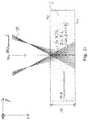
- Fig. 1outlines the basic procedure of steps (a), (b) and (d).
- a laser 12(not shown here) ( Fig. 10 ) Emitted laser beam 3, which is designated by the reference symbol 3a on the beam entrance side of the optical arrangement 20, is radiated onto the optical arrangement 20.
- the optical arrangement 20forms an extended laser beam focal line 3b from the incident laser beam on the beam exit side over a defined expansion area along the beam direction (length l of the focal line). At least in sections, covering the laser beam focal line 3b of the laser radiation 3, the flat substrate 2 to be processed is positioned in the beam path after the optical arrangement.
- the reference symbol 4vdenotes the surface of the flat substrate facing the optical arrangement 20 or the laser, the reference symbol 4r the rear surface of the substrate 2 which is usually parallel and spaced apart.
- the substrate thickness(perpendicular to the surfaces 4v and 4r, i.e. measured to the substrate plane) is denoted here by the reference number 10.
- FIG. 1ashows, here the substrate 2 is aligned perpendicular to the longitudinal axis of the beam and thus to the focal line 3b generated in space by the optical arrangement 20 behind it (the substrate is perpendicular to the plane of the drawing) and, viewed along the beam direction, is positioned relative to the focal line 3b so that the focal line 3b, viewed in the beam direction, begins in front of the surface 4v of the substrate and ends in front of the surface 4r of the substrate, that is to say still within the substrate.
- the extended laser beam focal line 3bis thus generated (with a suitable laser intensity along the laser beam focal line 3b, which is ensured by focusing the laser beam 3 on a section of length I, i.e.
- a line focus of length lin the area of overlap between the laser beam focal line 3b and the substrate 2, i.e. in the material of the substrate which is swept by the focal line 3b, a section 3c, seen along the longitudinal direction of the beam, along which an induced absorption is generated in the material of the substrate, which along section 3c induces cracking in the material of the substrate.
- the crack formationtakes place not only locally, but over the entire length of the extended section 3c of the induced absorption (i.e. the zone of internal damage).
- the length of this section 3c(that is to say ultimately the length of the overlap between the laser beam focal line 3b and the substrate 2) is provided with the reference symbol L here.
- the mean diameter or the mean extent of the section of the induced absorption (or the regions in the material of the substrate 2 which are subject to crack formation)is denoted here by the reference symbol D.
- This mean dimension Dhere essentially corresponds to the mean diameter ⁇ of the laser beam focal line 3b.
- FIG. 1ashows, substrate material transparent to the wavelength ⁇ of the laser beam 3 is thus heated by induced absorption along the focal line 3b.
- Figure 3bsketches that the heated material expands in the end, so that a correspondingly induced stress leads to the formation of microcracks, with the stress at the surface 4v being greatest.
- the individualshould be along e.g. of the contour line 5 on the surface of the substrate to be positioned focal lines 5-1, 5-2, ... are generated as described with the following optical arrangements (the optical arrangement is alternatively also referred to as laser optics below).
- the roughnessresults in particular from the spot size or the spot diameter of the focal line.
- certain requirementsare generally placed on the numerical aperture of the laser optics 20. These requirements are met by the laser optics 20 described below.
- the laser beamhas to illuminate the optics up to the necessary opening, which is typically accomplished by expanding the beam using expanding telescopes between the laser and the focusing optics.
- the spot sizeshould not vary too much for a uniform interaction along the focal line. This can be ensured, for example (see exemplary embodiment below), that the focusing optics are only illuminated in a narrow, ring-shaped area, in which the beam opening and thus the numerical aperture naturally change only slightly in percentage terms.
- the diameter of the diaphragm 20ais selected such that the beam bundles (here denoted by 3aZ) lying near the center of the beam bundle 3a or the central ray strike the diaphragm and are completely absorbed by it. Only rays lying in the outer circumferential area of the bundle of rays 3a (marginal rays, here designated 3aR) are not absorbed due to the diaphragm size, which is reduced compared to the beam diameter, but pass the diaphragm 20a laterally and hit the edge areas of the bi-convex lens, here as spherically ground 20b formed focusing optical element of the optical arrangement 20.
- the lens 20b centered on the central beamis here consciously designed as an uncorrected, bi-convex focusing lens in the form of a customary spherically ground lens.
- the spherical aberration of such a lensis consciously exploited.
- aspheres or multiple lenseswhich deviate from ideally corrected systems and which do not form an ideal focal point, but rather a pronounced, elongated focal line of a defined length, can be used (i.e. lenses or systems that no longer have a single focal point).
- the zones of the lensthus focus precisely as a function of the distance from the center of the lens along a focal line 3b.
- the diameter of the diaphragm 20a transversely to the beam directionis here about 90% of the diameter of the beam (beam diameter defined by the extent to the drop to 1 / e) and about 75% of the diameter of the lens of the optical arrangement 20. It thus becomes the focal line 3b of a non-aberration-corrected spherical lens 20b, which was generated by masking out the beam in the center. Shown is the section in a plane through the central ray, the complete three-dimensional bundle results if one the rays shown rotates around the focal line 3b.
- An improved usable optical arrangement 20is obtained if it comprises both an axicon and a focusing lens.
- Figure 3ashows such an optical arrangement 20 in which, viewed in the beam path of the laser 12 along the beam direction, a first optical element with a non-spherical free surface, which is shaped to form an extended laser beam focal line 3b, is initially positioned.
- this first optical elementis an axicon 20c with a 5 ° cone angle, which is positioned perpendicular to the beam direction and centered on the laser beam 3.
- An axicon or cone prismis a special, conically ground lens that forms a point source on a line along the optical axis (or transforms a laser beam into a ring).
- the structure of such an axiconis basically known to the person skilled in the art; the cone angle is here, for example, 10 °.
- a second, focusing optical elementhere a plano-convex lens 20d (the curvature of which points towards the axicon) is positioned in the beam direction at a distance z1 from the axicon 20c.
- the distance z1is selected here to be approximately 300 mm so that the laser radiation formed by the axicon 20c strikes the outer regions of the lens 20d in a ring shape.
- the lens 20dfocuses the ring-shaped incident radiation on the beam exit side at a distance z2 of here approx. 20 mm from the lens 20d onto a focal line 3b of a defined length of here 1.5 mm.
- the effective focal length of the lens 20dis 25 mm here.
- the ring-shaped transformation of the laser beam by the axicon 20cis provided here with the reference symbol SR.
- Figure 3bshows the formation of the focal line 3b or the induced absorption 3c in the material of the substrate 2 according to FIG Fig. 3a in detail.
- the optical properties of the two elements 20c, 20d as well as the positioning of the sametake place here in such a way that the extension 1 of the focal line 3b in the beam direction exactly matches the thickness 10 of the substrate 2. Accordingly, precise positioning of the substrate 2 along the beam direction is necessary in order, as in FIG Figure 3b shown to position the focal line 3b exactly between the two surfaces 4v and 4r of the substrate 2.
- the focal lineis formed at a certain distance from the laser optics and the majority of the laser radiation is focused up to a desired end of the focal line.
- Thiscan be achieved, as described, in that a mainly focusing element 20d (lens) is only illuminated in a ring shape on a desired zone, whereby on the one hand the desired numerical aperture and thus the desired spot size is realized, but on the other hand according to the desired focal line 3b of the
- the circle of confusionloses intensity over a very short distance in the center of the spot, since a substantially ring-shaped spot is formed. Thus, the cracking is stopped within a short distance in the desired depth of the substrate.
- a combination of Axicon 20c and focus lens 20dmeets this requirement.
- the axicon 20cworks in two ways: through the axicon 20c, a usually round laser spot is sent in the shape of a ring onto the focusing lens 20d and the asphericity of the axicon 20c causes a focal line to form outside the focal plane instead of a focal point in the focal plane of the lens.
- the length I of the focal line 3bcan be adjusted via the beam diameter on the axicon.
- the numerical aperture along the focal linecan in turn be set via the distance z1 axicon-lens and via the cone angle of the axicon. In this way, the entire laser energy can be concentrated in the focal line.
- the ring-shaped lightingstill has the advantage that, on the one hand, the laser power is used as best as possible, since a large part of the laser light remains concentrated in the desired length of the focal line
- a uniform spot size along the focal lineand that a uniform separation process can thus be achieved along the focal line.
- Borosilicate or sodalime glasses 2 without any other coloringare optically transparent from approx. 350 nm to approx. 2.5 ⁇ m. Glasses are generally poor heat conductors, which is why laser pulse durations of a few nanoseconds do not allow any significant heat diffusion out of a focal line 3b. Nevertheless, even shorter laser pulse durations are advantageous, since with sub-nanosecond or picosecond pulses a desired induced absorption can be achieved more easily via non-linear effects (intensity is significantly higher).
- a commercially available picosecond laser 12which has the following parameters, is suitable for cutting through flat glass: wavelength 1064 nm, pulse duration of 10 ps, pulse repetition frequency of 100 kHz, average power (measured directly after the laser) of up to 50 W.
- the laser beaminitially has a beam diameter (measured at 13% of the peak intensity, ie 1 / e 2 diameter of a Gaussian beam) of approx. 2 mm, the beam quality is at least M 2 ⁇ 1.2 (determined in accordance with DIN / ISO 11146).
- a beam expansion opticscommercially available beam telescope according to Kepler
- the beam diametercan be increased by a factor of 10 to approx. 20-22 mm.
- the inner part of the beamis shielded with a so-called annular diaphragm 20a with a diameter of 9 mm, so that an annular beam is formed.
- a plano-convex lens 20b with a focal length of 28 mm (quartz glass with a radius of 13 mm)is illuminated with this ring-shaped beam.
- the focal lineis created by the strong (desired) spherical aberration of the lens 20b.
- the theoretical diameter ⁇ of the focal linevaries along the beam axis, which is why it is advantageous for generating a homogeneous crack surface if the substrate thickness 10 is less than approx. 1 mm here (typical thicknesses for display glasses are 0.5 mm to 0.7 mm).
- the resultis a speed of 0.5 m / sec at which the focal line can be guided along the contour line 5 over the substrate 2 (cf. Fig. 4 ).
- the pulse repetition frequency of 100 kHzresults in a pulse energy of 250 ⁇ J, which is also generated in a structured pulse (rapid succession of individual pulses at an interval of only 20 ns, so-called burst pulse ) of 2 to 5 sub-pulses can take place.
- the swelling intensity for the process(induced absorption and formation of a fault zone through thermal shock) must naturally be achieved over a longer focal line l.
- higher necessary pulse energies and higher average powersfollow.
- the optics structure described above and the maximum available laser line (after losses through optics) of 39 W on the substrateit is possible to cut through approx. 3 mm thick glass.
- the annular diaphragm 20ahas been removed and, on the other hand, the distance between lens 20b and substrate has been corrected (increased in the direction of the nominal focus distance) so that a longer focal line is created in the substrate.
- Sodium-containing glassesare hardened by immersing them in liquid potassium salt baths on the surface of the glass to replace sodium with potassium. This leads to considerable internal stress (compressive stress) in a 5-50 ⁇ m thick layer on the surfaces, which in turn leads to greater stability.
- the process parameters for cutting through hardened glassesare similar to those for unhardened glasses of comparable dimensions and composition.
- the hardened glasscan break much more easily due to the internal tension, namely due to undesired crack growth, which is not along the lasered predetermined breaking surface 5, but into the Material is made into it. Therefore, the parameter field for the successful severing of a specific hardened glass is narrower.
- the mean laser power and the associated cutting speedmust be adhered to very precisely, depending on the thickness of the hardened layer.
- the above-mentioned structureresults in the following parameters, for example: Cutting speed of 1 m / s at 100 kHz pulse repetition frequency, therefore a spot spacing of 10 ⁇ m with an average power of 14 W.
- the sequence of steps (a) to (c) (preferably with (d))is crucial in order to prevent undesired cracks and destruction in the substrate 2 that remains.
- Very thin hardened glassesconsist mainly of strained material, i.e. Front and back are e.g. 30 ⁇ m in sodium depleted and thus hardened, and only 40 ⁇ m inside are uncured. This material shatters very easily and completely if one of the surfaces is damaged.
- Such hardened glass foilswere previously not workable in the prior art, but they can be with the method presented.
- This materialcan be severed if a) the diameter of the focal line is very small, e.g. less than 1 ⁇ m, b) the distance from spot to spot is small, e.g. between 1 and 2 ⁇ m, and c) the cutting speed is high enough so that the crack growth cannot precede the laser process (high laser pulse repetition frequency e.g. 200 kHz at 0.2 to 0.5 m / s).
- high laser pulse repetition frequencye.g. 200 kHz at 0.2 to 0.5 m / s.
- Figure 4shows a microscope image of the surface of a glass pane processed according to step (a).
- the pulse repetition frequency of the laserbeing matched to the feed rate for moving the laser beam across the surface 4v in the case shown the ratio a / ⁇ from the mean distance a between immediately adjacent sections 5-1, 5-2, ... and the mean diameter ⁇ of the laser beam focal line is approximately 2.0.
- Figures 5a-5dshow by way of example the processing of a 0.7 mm thick glass substrate 2 in a plan view of the substrate plane.
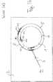
- FIG. 5ashows, in the contour definition step (a) the laser beam 3 of a Nd: YAG laser with a wavelength lambda of 1064 ⁇ m (the laser 12 is not shown here) is radiated perpendicularly onto the substrate plane and guided along the contour line 5 characterizing the contour 1 to be generated.
- the contour 1 to be generatedis here a circular inner contour that is to be cut out of the substrate 2.
- the aim of the processingis thus to produce an exactly circular hole in the substrate 2.
- the circular inner contour 1 or the substrate material thereofcan be destroyed during process steps (a) to (d), since the remaining substrate sections 2 represent the desired production product.
- FIG. 5ashows a multitude of individual zones 5-1, 5-2, ... of internal damage (sections of induced absorption along a section of the laser beam which is extended in the direction of the beam) along the contour line 5 in the substrate material due to the pulsed operation of the laser 12 by means of the laser beam 3 generated laser beam focal line).
- the individual zones of internal damagebecome like too Figure 4 generated (this also applies to the following steps (d) and (b)).
- a stress relief step (d) following step (a), cf. Figure 5b(in which the already in Figure 5a features described are provided with identical reference numerals; this also applies to the following Figures 5c and 5d ), concentrically within the contour line 5 and at a distance from the latter, i.e. in the material of the inner contour 1, a relief line section 11 approximating the course of the contour line 5 (here by constant distance from it) is introduced.
- the relief line section 11, which is also circular here,is introduced by means of the laser 12 with the same laser parameters as for the contour line 5, so that a large number of individual zones 11-1, 11-2, ... inner along the entire circumference of the section 11 in the substrate material Damage is generated. The introduction of these zones is carried out as in Figure 4 described.
- This step (d)is used to achieve a stress relief, i. H.
- a stress reliefi. H.
- This cutcan have a spiral shape, but can also be designed as a "circle-within-a-circle", which approximates the contour line.
- the aim of this cutis to minimize the distance between the relief line section 11 and the target contour in order to leave as little material as possible and thus enable or promote self-detachment.
- Example values for the maximum approximation of the relief line section 11 to the contour line 5are approx. 20 ⁇ m to 50 ⁇ m here.
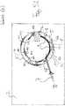
- Figure 5cshows the crack definition step (b) performed after the stress relief step (d).
- the laser beam 3 of the laser 12is guided over the substrate surface or the inner contour surface, so that here too a large number of individual zones 6-1 along the structures 6 inscribed in the inner contour 1 , 6-2, ... internal damage as in Figure 4 shown.
- FIG. 5cshows several straight lines, starting at a location on the contour line 5, of the contour line 5 each at an angle ⁇ of
- tear line sections 6a, 6b, ... leading away 25 ° and into the contour 1 to be cutare generated.
- Exactly two tear line sections(for example, tear line sections 6a and 6b) begin at one and the same location on contour line 5 and extend in opposite directions at angle ⁇ into inner contour 1 to such an extent that they intersect previously introduced relief line section 11 .
- the angle ⁇is the angle between the tangent to the contour line 5 at the point at which the two tear line sections (for example sections 6a and 6b or also sections 6c) leading from this location in essentially opposite directions into the material of the inner contour 1 and 6d) begin, and the tangent to the respective tear line section at this location (or the tear line section itself, since this coincides with its tangent).
- V-shaped tear lines 6Veach consisting of exactly two tear line sections beginning at one and the same place on the contour line 5, are drawn along the entire circumference of the contour line 5, which extend from the contour line 5 over the one between this and the relief line section 11 lead away surface sections of the inner contour 1, intersect the relief line section 11 and lead into the area of the inner contour 1 lying within the relief line section 11.
- the two legs of one and the same V-shaped tear line 6Vlead along the tangents to the contour line 5 at the point of the tip of the respective tear line, seen symmetrically to the normal on this tangent, i.e. on both sides of the normal, into the inner contour 1.
- the tear line sections 6a, 6b, ...do not necessarily have to start directly at a location on the contour line 5, even if this is preferred, but can also begin at a location in the inner contour material 1 at a slight distance from the contour line 5 and via the Relief line section 11 can also be guided into the material section located within it (the angle ⁇ is then between the imaginary line of intersection of the respective tear line section with the contour line 5 on the one hand and the tangent to the contour line 5 on the other hand).
- V-shaped tear linesare preferably produced along the circumference of the circular lines 5, 11.
- the tear lines 6V or the tear line sections 6a, 6b, ... of the sameare preferably placed and aligned in such a way that the triggering behavior during and / or after the material-removing laser step (c) is improved.
- the ring of material remaining after the material-removing laser step (c)is specifically segmented in such a way that individual segments of the circular ring can be released more easily.
- An attemptis made to build up an inwardly directed tension in the V-cuts, so that the subsegments are pressed inward as automatically as possible after the material-removing laser step (c).
- these V-cutsare not a must, as the procedure can also work without them.
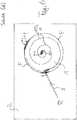
- Figure 5dfinally shows the material removal step (c) carried out after the crack definition step (b). (In Figure 5d For reasons of clarity, only three of the V-shaped tear lines introduced in step (b) are shown.)
- a material-removing laser beam 7 generated by a laser 14(not shown here) is directed onto the substrate surface.
- the parameters of the material-removing laser beam 7differ from the laser beam 3 as follows: A punctiform focus or punctual damage with associated material removal is used. Wavelength: between 300 nm and 11000 nm; particularly suitable 532 nm or 10600 nm. Pulse durations: 10 ps, 20 ns or even 3000 ⁇ s.
- FIG. 5dshows, with the laser beam 7 within the relief line section 11 in the material of the inner contour 1, an abrasion line 9, which is also circular here and extends along the entire circumference of the contour circle 5 or the relief line circle 11 (only partially shown here), is inscribed.
- the distance between the removal line 9 and the relief line 11is here about 25% of the distance between the relief line 11 and the outer contour line 5.
- the distance 8 between the removal line 9 and the contour line 5is thus 1.25 times the distance of the relief line 11 from the contour line 5.
- the removal line 9is introduced in such a way that it still intersects the inner ends of the tear line sections 6a, 6b, ... (viewed from the center of the inner contour 1).
- the material sections lying within the removal line 9 in the center of the inner contour 1detach from the substrate 2, since the substrate material is removed along the removal line 9 over the entire substrate thickness 10 (cf. . Fig. 9 ).
- the inner contour material 1 to be separatedonly the ring sections lying between the removal line 9 and the contour line 5 remain.
- the remaining, undesired contour residues 1r(which also include the stress relief sections 1 ') can be mediated a mechanical stamp movable perpendicular to the substrate plane can be separated from the remaining substrate 2.
- Figure 6shows an alternative form of the introduction of a relief line section 11 into the substrate material of the inner contour 1 to be separated Figure 5a .
- a relief spiral 11Swhich approximates the course of the contour line 5 and is wound into one another as seen from the center of the inner contour 1 radially outwards, here about 3.5 times circumferential, can be inscribed in the material of the inner contour 2 to be separated.
- the present inventioncan be used not only for severing closed inner contours 1 from a substrate 2, but also for severing complexly shaped outer contours 1, the shape of which (compare, for example, the dovetail-shaped section of the contour line 5 in FIG Figure 7 ) is such that the outer contour 1 of the substrate 2 cannot be implemented using methods known from the prior art without introducing stress cracks into the remaining substrate material 2.
- the angle ⁇ of the two opposite legs of the V-shaped tear lines 6V-1, 6V-2,... Lying here between the contour line 5 on the one hand and the removal line 9 on the other handis 10 ° here.
- otherwise identical reference symbolsdesignate identical or corresponding features as in FIG Figures 5a to 5d .
- the substrate thickness perpendicular to the substrate planeis identified with the reference symbol 10.
- the inventioncan therefore also be used, in particular, for severing contours with undercuts.
- Figure 8shows several different ways of how along the course the contour line 5, each essentially starting at the contour line 5 and leading into the material of the contour 1 to be cut off, tear line sections 6a, 6b, ... can be realized:
- Figure 8ashows V-shaped standard tear lines (see also Figure 5c ).
- Figure 8bshows V-shaped multiple tear lines along the contour line course 5, in which adjacent V-shaped tear lines intersect on the facing legs.
- Figure 8cshows open tear lines by introducing only one leg of a V-shaped tear line.
- Figure 9shows how with an additional precipitation material 18 (here: polyoxymethylene) the inner material section of an inner contour 1 to be separated, which is completely separated from the substrate 2 or the contour residues 1r after the removal line 9 has been introduced (possibly also with parts of the contour residues 1r undesirably still adhering to the substrate 2 ) can be driven out.
- an additional precipitation material 18here: polyoxymethylene
- FIG. 9shows how with an additional precipitation material 18 (here: polyoxymethylene) the inner material section of an inner contour 1 to be separated, which is completely separated from the substrate 2 or the contour residues 1r after the removal line 9 has been introduced (possibly also with parts of the contour residues 1r undesirably still adhering to the substrate 2 ) can be driven out.
- Identical reference charactersdenote in Figure 9 (and also in Figure 10 ) again the features of the invention already described under these reference symbols.
- the beam power of the material-removing laser beam 7, which is high compared to the laser beam 3,is transmitted via a (second, compare Figure 10 ) beam-guiding optical unit 21 coupled onto substrate 2.
- the substrate 2is mounted in a clamping device 16 (for example what is known as a chuck) in such a way that a gas-tight cavity 17 is formed in an area below the inner contour 1 to be separated on the substrate rear 4r.
- a clamping device 16for example what is known as a chuck
- Precipitation material 18was previously introduced into this cavity 17, which is now produced at the beginning of the material removal step shown (c) by focusing the laser beam 7 through the substrate 2 by means of the optical unit 21 is evaporated through into the cavity 17 ( Figure 9a ).
- the evaporated precipitation materialis deposited on the section of the substrate rear side 4r located in the cavity 17 and forms ( Figure 9b ) on at least one surface of the substrate rear 4r corresponding to the inner contour 1 to be separated out, a coupling-in layer 18 'which improves the coupling of the laser beam 7 into the substrate material.
- the evaporation of the material 18 to deposit on the back surface 4ris carried out for about ... seconds.
- the material of the substrate 2is transparent for the laser radiation ⁇ , but the material of the layer 18 'is opaque for ⁇ , the coupling of the beam 7 into the substrate material is thus improved.
- the laser radiation 7is then focused 15 through the optical unit 21 and through the substrate onto the rear surface 4r (cf. Figure 9b ).
- the focal point 15 of the laser radiation 7is guided successively from the substrate rear 4r to the substrate front 4v by repeatedly revolving the beam 7 along the line 9, in order to see the substrate material along the removal line 9 over the entire substrate thickness 10 to be removed successively or to evaporate due to the high laser energy introduced.
- the large numbere.g.
- Figure 10outlines a device for carrying out the method, which is provided with a beam generating and beam shaping arrangement 19 formed in a common laser head.
- the unit 19comprises the two lasers 12 (for generating the laser beam 3, which generates the individual zones of internal damage with lower laser intensity) and 14 (for generating the material-removing laser beam 7 of higher intensity), as well as two beam-guiding optical units 20 and 21, each one corresponding to an F.
- -Theta lenshave downstream galvanometer scanner for beam deflection (the structure of such optical units is known to the person skilled in the art).
- the laser radiation 3 of the laser 12is thus guided via the F-theta lens and the galvanometer scanner of the unit 20 in a focused manner onto the surface of the substrate 2 and appropriately deflected by means of the galvanometer scanner to generate the contour line 5.
- the laser radiation 7 of the laser 14 via the F-theta objective and the galvanometer scanneris correspondingly Unit 21 is imaged focused on the surface of the substrate 2 and deflected by the galvanometer scanner of the unit 21 to generate the removal line 9.
- fixed opticscan also be used instead of moving optics (then the substrate is moved).
- a central control unitdesigned here in the form of a PC 22 with suitable memories, programs, etc., controls the beam generation, beam focusing and beam deflection by means of the unit 19 via a bidirectional data and control line 23.
- Differences between the beam guidance optics 20 and 21 for generating the two different laser beams 3 and 7are as follows:
- the laser beam 7is compared to the beam 3 z. B. with a corrected F-theta lens on the surface, which leads to the formation of a point focus.
- the focal length of the lens for beam 7is significantly greater than for beam 3, e.g. B. 120 mm compared to 40 mm.
Landscapes
- Engineering & Computer Science (AREA)
- Chemical & Material Sciences (AREA)
- Physics & Mathematics (AREA)
- Optics & Photonics (AREA)
- Materials Engineering (AREA)
- Organic Chemistry (AREA)
- Mechanical Engineering (AREA)
- Plasma & Fusion (AREA)
- Health & Medical Sciences (AREA)
- Toxicology (AREA)
- Thermal Sciences (AREA)
- Chemical Kinetics & Catalysis (AREA)
- General Chemical & Material Sciences (AREA)
- Oil, Petroleum & Natural Gas (AREA)
- Laser Beam Processing (AREA)
- Re-Forming, After-Treatment, Cutting And Transporting Of Glass Products (AREA)
- Processing Of Stones Or Stones Resemblance Materials (AREA)
Description
Translated fromGermanDie vorliegende Erfindung bezieht sich auf eine Vorrichtung und auf ein Verfahren zum Ausschneiden von Konturen aus flächigen Substraten (insbesondere: Glassubstraten oder Kristallsubstraten) mittels Laser.The present invention relates to a device and a method for cutting out contours from flat substrates (in particular: glass substrates or crystal substrates) by means of a laser.
Die
Die
Die
Die
Die
Ausgehend vom Stand der Technik ist es daher die Aufgabe der vorliegenden Erfindung, ein Verfahren (sowie eine entsprechende Vorrichtung) zur Verfügung zu stellen, mit dem flächige Substrate insbesondere aus spröden Materialien mit minimaler Rissbildung an Rändern, mit möglichst geraden Schnittkanten, mit hoher Prozessgeschwindigkeit so bearbeitet werden können, dass aus diesen Substraten Konturen herausgearbeitet (und schließlich abgetrennt) werden können, ohne dass es zu unerwünschten, in der Substratebene verlaufenden Rissen, Abplatzungen oder anderen Zerstörungen im nach dem Abtrennen der Konturen verbleibenden Substrat kommt. Ziel der vorliegenden Erfindung ist somit das exakte, saubere Abtrennen einer Kontur von einem Substrat, insbesondere das saubere, exakte Heraustrennen von Innenkonturen aus dem Substrat.Based on the prior art, it is therefore the object of the present invention to provide a method (and a corresponding device) with which flat substrates, in particular made of brittle materials, with minimal cracking at edges, with cut edges that are as straight as possible, with high process speed can be processed so that contours can be carved out of these substrates (and finally cut off) without undesired cracks, flaking or other damage occurring in the substrate remaining after the contours have been cut off. The aim of the present invention is thus the exact, clean separation of a contour from a substrate, in particular the clean, exact separation of inner contours from the substrate.
Wie nachfolgend noch im Detail beschrieben wird, wird in der Regel mit einem gepulsten Laser mit einer Wellenlänge gearbeitet, für die das Substratmaterial im Wesentlichen transparent ist. Grundsätzlich ist jedoch auch der Einsatz eines Dauerstrichlasers möglich, sofern der Laserstrahl bei seinem Führen über die Substratoberfläche (z.B. mittels eines optischen Modulators) schnell an- und wieder abgeschaltet werden kann um hintereinander liegenden Zonen innerer Schädigung zu erzeugen (siehe nachfolgend).As will be described in detail below, a pulsed laser with a wavelength for which the substrate material is essentially transparent is generally used. In principle, however, the use of a continuous wave laser is also possible, provided that the laser beam can be quickly switched on and off when it is guided over the substrate surface (e.g. by means of an optical modulator) in order to generate zones of internal damage lying one behind the other (see below).
Die erfindungsgemäße Aufgabe wird durch ein Verfahren nach Anspruch 1 sowie durch eine Vorrichtung nach Anspruch 15 gelöst, wobei vorteilhafte Varianten in den abhängigen Ansprüchen beschrieben werden.The object according to the invention is achieved by a method according to
Nachfolgend wird die Erfindung zunächst allgemein, dann anhand von Ausführungsbeispielen beschrieben.In the following, the invention is first described in general, then on the basis of exemplary embodiments.
Die wesentlichen Merkmale des erfindungsgemäßen Verfahrens sind in Anspruch 1 beschrieben. Dabei wird die Kontur als zweidimensionale Fläche in der Substratebene in Form einer Teilfläche des Substrats verstanden. Die dieser Teilfläche entsprechenden Abschnitte des Substrats sollen aus dem Substrat entfernt werden wobei die übrigbleibenden Abschnitte des Substrats in nachfolgenden Prozessen weiterverarbeitet werden sollen. Anders ausgedrückt: Die vom Substrat abzutrennende Kontur bildet eine unerwünschte Fläche, die auch zerstört werden kann, die übrig bleibenden Substratabschnitte sollen den Abtrennprozess der Kontur ohne innere Beschädigungen sowie mit möglichst idealen Schnittkanten gemäß der Konturlinie überstehen. Dies wird erreicht. Nachfolgend wird/werden dabei unter dem Substrat sowohl das noch unbearbeitete Substrat vor Abtrennen der Kontur als auch die übrigbleibenden Substratreste nach dem Abtrennen der Kontur verstanden. Der Fachmann weiß jeweils aus dem Zusammenhang was gemeint ist.The essential features of the method according to the invention are described in
Der Konturdefinitionsschritt erfolgt so, dass nach seiner Durchführung der Konturverlauf der Kontur ins Substratmaterial eingeschrieben ist, die Kontur jedoch noch mit dem Substrat verbunden ist, sodass noch keine vollständige Trennung der Kontur vom Substrat erfolgt ist: Die schrittweise vollständige Abtrennung der unerwünschten Kontur vom Substrat erfolgt durch den Konturdefinitionsschritt, den optionalen Rissdefinitionsschritt, den optionalen Spannungsentlastungsschritt, und den Materialabtrags- und optional zusätzlichen Materialverformschritt und, sofern noch notwendig (also falls die Konturreste nicht bereits nach Durchführen der Schritte (a) bis (d) durch Eigenspannungen im Material selbstständig abfallen), durch einen optionalen Nachbehandlungsschritt. Auch die Einbringung der einzelnen Zonen innerer Schädigung im optionalen Rissdefinitionsschritt (vgl. Anspruch 3) und im optionalen Spannungsentlastungsschritt erfolgt so, dass noch keine vollständige Trennung der hierdurch erzeugten Teilabschnitte im Substrat erfolgt.The contour definition step is carried out in such a way that after it has been carried out, the contour course of the contour is written into the substrate material, but the contour is still connected to the substrate, so that the contour has not yet been completely separated from the substrate: The undesired contour is completely separated from the substrate in steps through the contour definition step, the optional crack definition step, the optional Stress relief step, and the material removal and optionally additional material deformation step and, if still necessary (i.e. if the contour residues do not fall off automatically after performing steps (a) to (d) due to internal stresses in the material), by an optional post-treatment step. The introduction of the individual zones of internal damage in the optional crack definition step (cf. claim 3) and in the optional stress relief step is also carried out in such a way that the partial sections produced in this way are not yet completely separated in the substrate.
Die Durchführung des optionalen Rissdefinitionsschritts erfolgt bevorzugt nach Abschluss des Konturdefinitionsschrittes, dies ist jedoch nicht notwendig: So können z.B. auch erst Teilabschnitte der Konturlinie durch Einbringen der Zonen innerer Schädigung erzeugt werden, bevor der Rissdefinitionsschritt zum Einbringen der Risslinienabschnitte durchgeführt wird und nach Abschluss desselben die restlichen Konturlinienabschnitte des Konturdefintionsschritts ins Substratmaterial eingebracht werden.The optional crack definition step is preferably carried out after the contour definition step has been completed, but this is not necessary: For example, also only partial sections of the contour line are generated by introducing the zones of internal damage, before the crack definition step for introducing the tear line sections is carried out and after this has been completed the remaining contour line sections of the contour definition step are introduced into the substrate material.
Unter dem Begriff eines von der Konturlinie unter einem Winkel α > 0° wegführenden Risslinienabschnitts wird verstanden, dass der Winkel α zwischen der lokalen Tangente an die Konturlinie an demjenigen Ort, wo besagter (ggf. zur Konturlinie hin fortgesetzter) Risslinienabschnitt von der Konturlinie wegführt, und der lokalen Tangente an demjenigen Ende des Risslinienabschnitts, das der Konturlinie zugewandt ist, größer als 0° ist.The term of a tear line section leading away from the contour line at an angle α> 0 ° is understood to mean that the angle α between the local tangent to the contour line at that location where said tear line section (possibly continued towards the contour line) leads away from the contour line, and the local tangent at that end of the tear line section which faces the contour line is greater than 0 °.
Die Laserbestrahlung in den Schritten (a), (b) und (d) (also im Konturdefinitionsschritt, im Rissdefinitionsschritt und im Spannungsentlastungsschrittnachfolgend werden alternativ auch diese Bezeichnungen (a) bis (d) für diese Schritte verwendet) muss nicht senkrecht zur Substratebene erfolgen, d.h. die einzelnen Zonen innerer Schädigung müssen nicht senkrecht zur Substratebene verlaufen (und auch nicht unbedingt die gesamte Substratdicke senkrecht zur Substratebene durchziehen). Die Lasereinstrahlung kann auch unter einem Winkel > 0° (beispielsweise zwischen 0° und 20°) zur Substratnormalen erfolgen (schräges Einbringen der Zonen innerer Schädigung).The laser irradiation in steps (a), (b) and (d) (i.e. in the contour definition step, in the crack definition step and in the stress relief step below, these terms (a) to (d) are also used for these steps) need not be perpendicular to the substrate plane, ie the individual zones of internal damage do not have to run perpendicular to the substrate plane (nor do they necessarily have to extend through the entire substrate thickness perpendicular to the substrate plane). The laser irradiation can also take place at an angle> 0 ° (for example between 0 ° and 20 °) to the substrate normal (oblique introduction of the zones of internal damage).
Unter den bevorzugt bearbeiteten (d.h. einzubringenden und herauszulösenden) Innenkonturen werden mathematisch gesprochen einfach zusammenhängende Mengen des zweidimensionalen Raumes (Ebene des Substrats) bzw. entsprechende Teilabschnitte im Substrat verstanden. Die herauszutrennenden Innenkonturen können dabei nahezu beliebige Formen aufweisen. Insbesondere sind Kreisformen, Ellipsenformen, Kissenformen, Langlochformen (mit abgerundeten Ecken) usw. für die Innenkonturen möglich, indem der Laserstrahl auf der Substratoberfläche entlang einer entsprechend geformten Konturlinie bewegt wird. Bevorzugt ist das Substrat dabei ortsfest im Weltkoordinatensystem angeordnet und der Laserstrahl wird mit einer geeigneten strahlführenden optischen Einheit (die beispielsweise ein F-Theta-Objektiv gefolgt von einem Galvanometerscanner aufweisen kann) über die Substratoberfläche bewegt. Alternativ ist auch eine relativ zum Weltkoordinatensystem feststehende Strahlführungsoptik möglich, wobei dann relativ zur Strahlführungsoptik und zum Laserstrahl das Substrat im Weltkoordinatensystem bewegt werden muss.Mathematically speaking, the inner contours that are preferably machined (ie to be introduced and removed) are simply connected Understand quantities of two-dimensional space (plane of the substrate) or corresponding subsections in the substrate. The inner contours to be separated can have almost any shape. In particular, circular shapes, elliptical shapes, pillow shapes, elongated hole shapes (with rounded corners) etc. are possible for the inner contours by moving the laser beam on the substrate surface along a correspondingly shaped contour line. The substrate is preferably arranged in a stationary manner in the world coordinate system and the laser beam is moved over the substrate surface with a suitable beam-guiding optical unit (which can for example have an F-theta objective followed by a galvanometer scanner). Alternatively, beam guiding optics that are fixed relative to the world coordinate system are also possible, the substrate then having to be moved in the world coordinate system relative to the beam guiding optics and the laser beam.
Unter der Substratdicke wird nachfolgend die Ausdehnung des Substrats senkrecht zur Substratebene, also zwischen Substratvorderseite und der Substratrückseite verstanden. Die Substratvorderseite ist dabei diejenige Oberfläche des Substrats, die dem eingestrahlten Laserlicht zugewandt ist.In the following, the substrate thickness is understood to mean the extent of the substrate perpendicular to the substrate plane, that is to say between the substrate front side and the substrate rear side. The substrate front is that surface of the substrate that faces the incident laser light.
Erste vorzugsweise realisierte Merkmale des erfindungsgemäßen Verfahrens (Materialabtragung zum Einbringen einer Abtraglinie) lassen sich Anspruch 2 entnehmen.The first features of the method according to the invention which are preferably implemented (material removal for introducing a removal line) can be found in
Diese Materialabtragung ist insbesondere auf große und kleine Radien von abzutrennenden Innenkonturen anwendbar und besonders für kleinere Konturen wie z.B. Kreisausschnitte mit Durchmesser < 2.5 mm und für Langlöcher geeignet.This material removal is particularly applicable to large and small radii of inner contours to be separated and especially for smaller contours such as e.g. Circular sections with a diameter of <2.5 mm and suitable for elongated holes.
Zum Materialabtrag kann ein CO2-Laser mit einem Strahldurchmesser beim Auftreffen auf das Substrat (durch Fokussierung erreicht) von im Bereich zwischen ca. 0.05 mm und 0.5 mm verwendet werden. Der CO2-Laser kann gepulst oder kontinuierlich angewendet werden. Bevorzugt werden Pulse im Bereich 100 µs bis 4000 µs verwendet bei Pulsfolgefrequenzen von 0.1 kHz bis 100 kHz. Besonders bevorzugt liegt die Pulsdauer im Bereich zwischen 300 µs und 4000 µs bei 0.1 kHz bis 3 kHz Pulsfolgefrequenz. Die Laserleistung kann im Bereich von 10 bis 200 W, bevorzugt aber im Bereich von 10 bis 100 W, liegen.A CO2 laser with a beam diameter when it hits the substrate (achieved by focusing) of between approx. 0.05 mm and 0.5 mm can be used to remove material. The CO2 laser can be used pulsed or continuously. Pulses in the range from 100 microseconds to 4000 microseconds are preferably used with pulse repetition frequencies from 0.1 kHz to 100 kHz. The pulse duration is particularly preferably in the range between 300 μs and 4000 μs at 0.1 kHz to 3 kHz pulse repetition frequency. The laser power can be in Range from 10 to 200 W, but preferably in the range from 10 to 100 W.
Der Verfahrweg des Laserstrahls ist längs der Konturlinie, beabstandet von dieser und in der abzutrennenden Kontur, beispielsweise also auf einer zur Targetkontur symmetrischen (parallelen) Bahn. Beispielsweise bei einer herauszutrennenden kreisförmigen Kontur (Lochausschnitt) eine Kreisbewegung. Der Verfahrweg kann entweder einmal oder mit mehrfacher Wiederholung ausgeführt werden.The travel path of the laser beam is along the contour line, at a distance from it and in the contour to be separated, for example on a path that is symmetrical (parallel) to the target contour. For example, a circular movement for a circular contour (hole cutout) to be cut out. The traverse path can be carried out either once or with multiple repetitions.
Durch den geringen Fokusdurchmesser und die hohen Laserleistungen wird Substratmaterial vorrangig geschmolzen (Materialabtrag). Zusammen mit Laserpulsen im oberen Mikrosekundenbereich kann so die gesamte Substratmaterialdicke (z.B. 0.7mm) mit einem Puls komplett durchgewärmt werden.Due to the small focus diameter and the high laser power, the substrate material is primarily melted (material removal). Together with laser pulses in the upper microsecond range, the entire substrate material thickness (e.g. 0.7mm) can be completely heated with one pulse.
Unterstützt werden kann der Materialabtragsschritt durch den Einsatz einer Gasdüse mit Prozessgas (z.B. CDA). Bei z.B. einem Düsendurchmesser von 2 mm und Gasdrücken von 1.5 bis 4 bar lässt sich besonders gut ein Materialabtrag auch für kleine Konturen und Radien herstellen. Durch den Gasfluss wird das durch den Laser aufgeschmolzene Material in Strahlrichtung ausgetrieben.The material removal step can be supported by using a gas nozzle with process gas (e.g. CDA). For e.g. With a nozzle diameter of 2 mm and gas pressures of 1.5 to 4 bar, material can be removed particularly well, even for small contours and radii. The material melted by the laser is expelled in the direction of the beam by the gas flow.
Mit den oben beschrieben Parametern können z.B. auch gehärtete Gläser (DOL 40 µm) einem Materialabtrag zugeführt werden ohne dass es zur schädlichen Rissbildung kommt.With the parameters described above, e.g. Even hardened glasses (DOL 40 µm) can be used for material removal without damaging cracks.
Die Abtragskontur (Abtraglinie) sollte ausreichend weit von der Konturlinie (Target-Konturschnitt) entfernt sein (in der Regel reichen hier, je nach Substratmaterial, Abstände von ca. 0.1 bis 0.3 mm): Beispielsweise bei einer herauszutrennenden kreisförmigen Glasscheibe von 2 mm Durchmesser sollte der Mindestabstand der Abtraglinie von der Konturlinie 0.1 mm betragen (Verformungsdurchmesser bzw. Durchmesser der kreisförmigen Abtragslinie maximal 1.8 mm). Bei einem Glasscheibendurchmesser von 1.5 mm sollte der Verformungsdurchmesser maximal 1.3 mm groß sein. Bei einem Glasscheibendurchmesser von 1.0 mm sollte der Verformungsdurchmesser maximal 0.8 mm groß sein.The removal contour (removal line) should be sufficiently far away from the contour line (target contour cut) (generally, distances of approx. 0.1 to 0.3 mm are sufficient here, depending on the substrate material): For example, with a circular pane of glass with a diameter of 2 mm the minimum distance between the removal line and the contour line is 0.1 mm (deformation diameter or diameter of the circular removal line maximum 1.8 mm). With a glass pane diameter of 1.5 mm, the deformation diameter should be a maximum of 1.3 mm. With a glass pane diameter of 1.0 mm, the deformation diameter should be a maximum of 0.8 mm.
Unterstützend für das vollständige Abtrennen der Kontur wirken sich die nachfolgend noch näher beschriebenen Risslinienabschnitte (z. B. V-Schnitte) aus.The support for the complete separation of the contour tear line sections (e.g. V-cuts) described in more detail below.
Gemäß der vorteilhaften Merkmale des Anspruchs 2 ist statt einer oder additiv zu einer Materialabtragung gemäß Anspruch 1 auch ein Herauslösen von Materialabschnitten der abzutrennenden Kontur durch thermische Verformung möglich.According to the advantageous features of
Dabei kann ein CO2-Laser bzw. dessen Laserstrahl zum Herauslösen von Substratmaterial in einer Substratmaterial nicht abtragenden Weise, also in Substratmaterial (insbesondere der abzutrennenden Kontur) rein thermisch verformender Weise verwendet werden (dies erfolgt vorzugsweise bei größeren abzutrennenden Konturen, z. B. bei herauszutrennenden Kreisausschnitten mit einem Durchmesser ≥ 2.5 mm, vorzugsweise ≥ 5-10 mm).A CO2 laser or its laser beam can be used to remove substrate material in a manner that does not remove the substrate material, i.e. in a purely thermally deforming manner in the substrate material (in particular the contour to be cut) (this is preferably done with larger contours to be cut, e.g. for circular sections with a diameter ≥ 2.5 mm, preferably ≥ 5-10 mm).
Die Vorgehensweise bei einem solchen Materialverformschritt kann wie folgt sein:
Durch CO2-Laser-Bestrahlung des Substrats werden z. B. durch Bewegen des Laserstrahls längs der Konturlinie, jedoch beabstandet davon sowie in der abzutrennenden Kontur (beispielsweise entlang eines Kreises oder einer Spirale im Zentrum der der abzutrennenden Kontur) zumindest Abschnitte der abzutrennenden Kontur so erwärmt, dass es zu einer plastischen Verformung von zumindest Abschnitten der abzutrennenden Kontur kommt. Der Durchmesser des auf dem Substratmaterial auftreffenden CO2-Laserspots kann einen weiten Bereich abdecken: 0.1 mm bis 10 mm. Bevorzug ist ein Durchmesser von 0.2 mm bis 3 mm. Der CO2-Laser kann sowohl gepulst als auch kontinuierlich betrieben werden. Bevorzugt werden aber Pulse im Bereich von 6 µs bis 4000 µs verwendet bei Pulsfolgefrequenzen im Bereich von 0.1kHz bis 100 kHz. Die Laserleistung kann Bereich zwischen 10 und 300 W, bevorzugt im Bereich zwischen 10 und 50 W liegen.The procedure for such a material deformation step can be as follows:
By CO2 laser irradiation of the substrate z. B. by moving the laser beam along the contour line, but at a distance from it and in the contour to be cut (for example along a circle or a spiral in the center of the contour to be cut) at least sections of the contour to be cut are heated so that there is a plastic deformation of at least sections the contour to be separated comes. The diameter of the CO2 laser spot hitting the substrate material can cover a wide range: 0.1 mm to 10 mm. A diameter of 0.2 mm to 3 mm is preferred. The CO2 laser can be operated both pulsed and continuously. However, pulses in the range from 6 μs to 4000 μs are preferably used with pulse repetition frequencies in the range from 0.1 kHz to 100 kHz. The laser power can be in the range between 10 and 300 W, preferably in the range between 10 and 50 W.
Der Verfahrweg des Lasers ist vorzugsweise eine zur abzutrennenden Kontur (Targetkontur) symmetrische (z. B. parallele, jedoch beabstandete) Bahn. Beispielsweise bei einem Lochausschnitt als abzutrennender Innenkontur eine Kreisbewegung. Aber auch eine Spiralbewegung kann sich günstig auf die thermoplastische Verformung einer solchen inneren Kontur (z. B. Glasscheibe) auswirken. Es kann sich in bestimmten Fällen als günstig erweisen, wenn der Laserstrahl über ein definiertes Zeitintervall von beispielsweise zwischen .... s und 0.5 s einfach im Zentrum der abzutrennenden Kontur stehenbleibt und die abzutrennende Kontur durchwärmt und so verformt. Der Verfahrweg kann entweder einmal oder mit mehrfacher Wiederholung ausgeführt werden, was sich günstig auf die thermoplastische Verformung der abzutrennenden Kontur auswirken kann.The travel path of the laser is preferably a path that is symmetrical (e.g. parallel, but spaced apart) to the contour to be cut (target contour). For example, in the case of a hole cutout as the inner contour to be separated, a circular movement. But a spiral movement can also have a beneficial effect on the effect thermoplastic deformation of such an inner contour (e.g. glass pane). In certain cases it can prove to be beneficial if the laser beam simply stops in the center of the contour to be cut over a defined time interval of, for example, between .... s and 0.5 s, and warms the contour to be cut and thus deforms it. The traverse path can be carried out either once or with multiple repetitions, which can have a favorable effect on the thermoplastic deformation of the contour to be separated.
Die plastische Verformung im Zentrum führt zu einem Zusammenziehen der abzutrennenden Kontur (z. B. Glasscheibe) aufgrund eines thermischinduzierten Fließens des Substratmaterials (z. B. Glasmaterial) im bestrahlten Bereich im Zentrum und zum Zentrum. Dies kann z. B. bei einer abzutrennenden Kreisscheibe als Kontur wie folgt aussehen:
- Die Verformung bildet schwerkraftbedingt i.d.R. eine Ausbeulung vom Laser weg in Richtung Erdmittelpunkt aus. Diese Ausbeulung kann u. U. eine Tropfenform annehmen. Vergleichen kann man die Oberflächentopografie mit der einer konvexen Linse.
- Unter bestimmten Laser-Bedingungen bildet sich auch zum Laser hin eine Ausbeulung aus. Die Oberflächentopografie ist dann die einer bikonvexen Linse.
- Unter bestimmten Laser-Bedingungen bildet sich einseitig eine Einbeulung (konkav) und auf der gegenüberliegenden Oberfläche eine Ausbeulung aus.
- Wenn parallel und zeitgleich über eine Gasdüse Prozessgas (technische Luft, CDA) auf die bestrahlte Oberfläche geströmt wird, kann die Bildung der Aus- und/oder Einbeulung sehr präzise gesteuert werden. Dadurch können auch Konturen mit sehr kleine Radien (<2,
5mm bis 1,2mm) zum Herauslösen gebracht werden. Bei z. B.einem Düsendurchmesser von 2 mm und Gasdrücken im Bereich von 1.5 bis -3 bar lassen sich besonders gut relativ kleine Konturen herauslösen.
- Due to gravity, the deformation usually forms a bulge away from the laser towards the center of the earth. This bulge can u. U. assume a teardrop shape. One can compare the surface topography with that of a convex lens.
- Under certain laser conditions, a bulge also forms towards the laser. The surface topography is then that of a biconvex lens.
- Under certain laser conditions a dent (concave) forms on one side and a bulge on the opposite surface.
- If process gas (technical air, CDA) is flowed onto the irradiated surface in parallel and at the same time via a gas nozzle, the formation of the bulge and / or indentation can be controlled very precisely. This allows contours with very small radii (<2.5mm to 1.2mm) to be detached. At z. B. a nozzle diameter of 2 mm and gas pressures in the range from 1.5 to -3 bar, relatively small contours can be extracted particularly well.
Gemeinsame haben die beschriebenen thermoplastischen Verformungsvarianten, dass Substratmaterial der abzutrennenden Kontur fließt (z. B. bei einer herauszutrennenden Innenkontur zum Zentrum derselben hin fließt) und sich dadurch ein Spalt zum restlichen Substratmaterial (z. B. außen liegendes Material einer herauszutrennenden Innenkontur) bildet. Ein solcher Spalt kann Abmessungen von ca. 10 µm bis 50 µm haben.What the thermoplastic deformation variants described have in common is that the substrate material of the contour to be separated flows (e.g. flows towards the center of an inner contour that is to be separated) and a gap is thus formed between the remaining substrate material (e.g. external material of an inner contour to be separated). Such a gap can have dimensions of approx. 10 µm to 50 µm.
Nach einer kurzen thermischen Relaxationszeit (Abkühlen und Zusammenziehen der abzutrennenden Kontur) fällt die abzutrennenden Kontur durch den sich bildenden Spalt allein heraus.After a short thermal relaxation time (cooling and contraction of the contour to be cut), the contour to be cut falls out through the gap that is being formed.
Beim Materialverformschritt wird somit kein Substratmaterial abgetragen, es entstehen keine Abtragsprodukte.In the material deformation step, no substrate material is removed, and no removal products arise.
Die CO2-induzierte thermoplastische Verformung bzw. die vom Laser bestrahlten Bereiche sollte(n) ausreichend weit (in der Regel reichen hier, je nach Substratmaterial, Abstände von ca. 1 bis 3 mm) von der bereits eingebrachten Konturlinie (Konturschnitt) entfernt sein: Beispielsweise bei einer herauszutrennenden Glasscheibe von 10 mm Durchmesser sollte der zentral in dieser Glasscheibe bestrahlte Bereich (Verformungsdurchmesser) maximal einen Durchmesser von 8 mm aufweisen. Bei einem Glasscheibendurchmesser von 5 mm sollte dieser Bereich maximal 3.4 mm groß sein. Bei einem Glasscheibendurchmesser von 2.5 mm sollte dieser Bereich maximal 1.5 mm groß sein.The CO2 -induced thermoplastic deformation or the areas irradiated by the laser should be sufficiently far (generally, depending on the substrate material, distances of approx. 1 to 3 mm are sufficient) from the contour line (contour cut) that has already been introduced : For example, in the case of a glass pane with a diameter of 10 mm to be removed, the area irradiated centrally in this glass pane (deformation diameter) should have a maximum diameter of 8 mm. With a glass pane diameter of 5 mm, this area should be a maximum of 3.4 mm. With a glass pane diameter of 2.5 mm, this area should be a maximum of 1.5 mm.
Die bereits eingebrachte Konturlinie (Target-Konturschnitt) bildet eine ausreichende thermische Isolation zum umliegenden Material des restlichen, verbleibenden Substrats, so dass bei geeignetem thermoplastischen Verformungsdurchmesser keine nachteilige thermische Beeinflussung des Schnittrandes bzw. des umliegenden Materials in Form von Chipping oder parasitärer Rissbildung erfolgen kann.The already introduced contour line (target contour cut) forms sufficient thermal insulation from the surrounding material of the remaining, remaining substrate, so that with a suitable thermoplastic deformation diameter there can be no disadvantageous thermal influence on the cut edge or the surrounding material in the form of chipping or parasitic cracking.
In den nachfolgenden Ausführungsbeispielen wird die Realisierung des Materialabtrags- und/oder Materialverformschrittes als Materialabtragsschritt mittels eines materialabtragenden Laserstrahls noch näher dargestellt.In the following exemplary embodiments, the implementation of the material removal and / or material deformation step is shown in greater detail as a material removal step by means of a material-removing laser beam.
Die Ultraschallbehandlung kann wie folgt erfolgen: Frequenzbereich zwischen 1 kHz und 50 kHz (besonders bevorzugt: 5kHz - 40kHz). Dabei wird bevorzugt die Fläche im Inneren der Schnittkontur (also in der abzutrennenden Kontur) mit einem Ultraschall-Aktor kontaktiert. Die Kontaktfläche kann dabei den Abmessungen und der Form einer herauszutrennenden Innenkontur entsprechen. Der Kontakt kann vollflächig oder als Ring ausgeführt sein. In einer besonderen Ausführung können auch außerhalb der abzutrennenden Kontur liegende Substratbereiche mit Ultraschall behandelt werden (auch eine gleichzeitige Ultraschallbehandlung der abzutrennenden Kontur und solcher Restsubstratbereiche ist möglich).The ultrasonic treatment can be carried out as follows: Frequency range between 1 kHz and 50 kHz (particularly preferred: 5 kHz-40 kHz). In this case, the surface in the interior of the cutting contour (that is to say in the contour to be separated) is preferably contacted with an ultrasonic actuator. The contact surface can correspond to the dimensions and the shape of an inner contour to be separated. The contact can be designed over the entire surface or as a ring. In a special embodiment, substrate areas lying outside the contour to be separated can also be treated with ultrasound (simultaneous ultrasound treatment of the contour to be separated and such remaining substrate areas is also possible).
Ein entsprechender Nachbehandlungsschritt ist jedoch häufig gar nicht notwendig, da die im Schritt (b) (und im ggf. durchgeführten optionalen Schritt (d)) eingebrachten Zonen innerer Schädigung bereits innere Spannungen in das Substratmaterial eingebracht haben, die ausreichen, dass sich die unerwünschten Konturreste im Verlauf des Materialabtrags- und/oder Materialverformschritts oder nach demselben von alleine vom übrigbleibenden Substrat lösen (Selbstentfernung der Konturreste).A corresponding post-treatment step, however, is often not necessary at all, since the zones of internal damage introduced in step (b) (and optionally carried out optional step (d)) have already introduced internal stresses into the substrate material, which are sufficient for the undesired contour residues to disappear in the course of the material removal and / or material deformation step or after the same, detach them from the remaining substrate by themselves (self-removal of the contour residues).
Alle der bereits beschriebenen vorteilhaften Merkmale und der nachfolgend noch beschriebenen vorteilhaften Merkmale lassen sich dabei im Rahmen der Erfindung jeweils einzeln oder auch in beliebigen Kombinationen miteinander realisieren.All of the advantageous features already described and the advantageous features described below can be implemented individually or in any combination with one another within the scope of the invention.
Das im Anspruch 7 beschriebene punktförmige Fokussieren kann dabei wie in
Besonders bevorzugt ist es jedoch, die einzelnen Zonen innerer Schädigung entlang der Konturlinie, der Risslinienabschnitte und ggf. auch der Entlastungslinienabschnitte vermittels der im Anspruch 7 beschriebenen Laserstrahlbrennlinie (also durch induzierte Absorption im Substratmaterial entlang eines ausgedehnten Abschnitts in Dickenrichtung des Materials) einzubringen.However, it is particularly preferred to introduce the individual zones of internal damage along the contour line, the tear line sections and possibly also the relief line sections by means of the laser beam focal line described in claim 7 (i.e. through induced absorption in the substrate material along an extended section in the thickness direction of the material).
Diese bevorzugte Ausführungsform der Schritte (a), (b) und (d) wird nun nachfolgend ausführlich beschrieben.This preferred embodiment of steps (a), (b) and (d) will now be described in detail below.
Wesentlich ist dabei zunächst, dass die Wellenlänge des einstrahlenden Lasers in Abstimmung mit dem zu bearbeitenden Substrat so gewählt wird, dass das Substratmaterial für diese Laserwellenlänge im wesentlichen transparent ist.First of all, it is essential that the wavelength of the irradiating laser is selected in coordination with the substrate to be processed so that the substrate material is essentially transparent for this laser wavelength.
Das Verfahren für die Schritte (a), (b) und (d) erzeugt pro Laserpuls eine Laser-Brennlinie (im Unterschied zu einem Brennpunkt) mittels einer dazu geeigneten Laseroptik (nachfolgend alternativ auch als strahlführende optische Einheit oder optische Anordnung bezeichnet). Die Brennlinie bestimmt die Zone der Wechselwirkung zwischen Laser und Material des Substrats. Fällt die Brennlinie in das zu trennende Material, so können die Laserparameter so gewählt werden, dass eine Wechselwirkung mit dem Material stattfindet, die eine Risszone entlang der Brennline erzeugt. Wichtige Laserparameter sind hier die Wellenlänge des Lasers, die Impulsdauer des Lasers, die Pulsenergie des Lasers und ggf. auch die Polarisation des Lasers.The method for steps (a), (b) and (d) generates a laser focal line (in contrast to a focal point) per laser pulse by means of laser optics suitable for this purpose (hereinafter also referred to alternatively as a beam-guiding optical unit or optical arrangement). The focal line determines the zone of interaction between the laser and the material of the substrate. If the focal line falls into the material to be cut, the laser parameters can be selected in such a way that an interaction with the material takes place, which creates a crack zone along the focal line. Important laser parameters here are the wavelength of the laser, the pulse duration of the laser, the pulse energy of the laser and possibly also the polarization of the laser.
Für die Wechselwirkung des Laserlichts mit dem Material in den Schritten (a), (b) und (d) sollte bevorzugt folgendes gegeben sein:
- 1)
Die Wellenlänge 1 des Lasers ist bevorzugt so gewählt, dass das Material im wesentlichen transparent bei dieser Wellenlänge ist (konkret z.B.: Absorption <<10% pro mm Materialtiefe => γ<<1/cm; γ: Lambert-Beer'scher Absorptionskoeffizient). - 2) Die Impulsdauer des Lasers ist bevorzugt so gewählt, dass innerhalb der Wechselwirkungszeit kein wesentlicher Wärmetransport (Wärmediffusion) aus der Wechselwirkungszone heraus stattfinden kann (konkret z.B.: τ << d2/α, d: Fokusdurchmesser, τ Laserimpulsdauer, α: Wärmediffusionskonstante des Materials).
- 3) Die Pulsenergie des Lasers ist bevorzugt so gewählt, dass die Intensität in der Wechselwirkungszone, also in der Brennlinie eine induzierte Absorption erzeugt, welche zu einer lokalen Erwärmung des Materials entlang der Brennlinie führt, welche wiederum zu einer Rissbildung entlang der Brennlinie infolge des in das Material eingebrachten thermischen Stresses führt.
- 4) Die Polarisation des Lasers beeinflusst sowohl die Wechselwirkung an der Oberfläche (Reflektivität), als auch die Art der Wechselwirkung innerhalb des Materials bei der induzierten Absorption. Die induzierte Absorption kann über induzierte, freie Ladungsträger (typischerweise Elektronen) stattfinden, entweder nach thermischer Anregung, oder über Multiphoton-Absorption und innere Photoionisation, oder über direkte Feldionisation (Feldstärke des Lichtes bricht Elektronenbindung direkt). Die Art der Erzeugung der Ladungsträger kann z.B. über den sog. Keldysh-Parameter (Referenz) beurteilt werden, das spielt aber für die Anwendung der Methode keine Rolle. Wichtig kann bei bestimmten (z.B. doppelbrechenden Materialien) nur sein, dass die weitere Absorption/Transmission des Laserlichtes von der Polarisation abhängt, und somit die Polarisation über geeignete Optiken (Phasenplatten) vom Anwender für das Trennen des jeweiligen Materials günstig gewählt werden sollte, z.B. einfach in heuristischer Weise. Ist also das Substratmaterial nicht optisch isotrop, sondern z.B. doppelbrechend, so wird auch die Propagation des Laserlichts im Material durch die Polarisation beeinflusst. So kann die Polarisation und die Orientierung des Polarisationsvektors so gewählt werden, dass sich wie gewünscht nur eine Brennlinie und nicht deren zwei ausbilden (ordentliche und außerordentliche Strahlen). Bei optisch isotropen Materialien spielt dies keine Rolle.
- 5) Weiterhin sollte die Intensität über die Impulsdauer, die Pulsenergie und den Brennliniendurchmesser so gewählt sein, dass keine Ablation oder Aufschmelzung, sondern nur eine Rissbildung im Gefüge des Festkörpers erfolgt. Diese Anforderung ist für typische Materialien wie Glas oder transparente Kristalle am leichtesten zu erfüllen mit gepulsten Lasern im Sub-Nanosekunden-Bereich, insbesondere also mit Pulsdauern von z.B. zwischen 10 und 100 ps. Über Skalenlängen von etwa einem Mikrometer (0.5 bis 5.0 Mikrometer) wirkt für schlechte Wärmeleiter wie beispielsweise Gläser die Wärmeleitung bis in den Sub-Mikrosekundenbereich, während für gute Wärmeleiter wie Kristalle und Halbleiter die Wärmeleitung schon ab Nanosekunden wirksam wird.
- 1) The
wavelength 1 of the laser is preferably chosen so that the material is essentially transparent at this wavelength (specifically, for example: absorption << 10% per mm of material depth => γ << 1 / cm; γ: Lambert-Beer'scher Absorption coefficient). - 2) The pulse duration of the laser is preferably chosen so that no significant heat transport (heat diffusion) can take place out of the interaction zone within the interaction time (specifically e.g. τ << d2 / α, d: focus diameter, τ laser pulse duration, α: heat diffusion constant des Materials).
- 3) The pulse energy of the laser is preferably chosen so that the intensity in the interaction zone, i.e. in the focal line, generates an induced absorption, which leads to local heating of the material along the focal line, which in turn leads to cracking along the focal line as a result of the in the material introduces thermal stress.
- 4) The polarization of the laser influences both the interaction on the surface (reflectivity) and the type of interaction within the material during the induced absorption. The induced absorption can take place via induced, free charge carriers (typically electrons), either after thermal excitation, or via multiphoton absorption and internal photoionization, or via direct field ionization (field strength of the light breaks electron bonds directly). The type of generation of the charge carriers can be assessed, for example, using the so-called Keldysh parameter (reference), but this is irrelevant for the application of the method. With certain (e.g. birefringent materials) it can only be important that the further absorption / transmission of the laser light depends on the polarization, and thus the polarization should be chosen favorably by the user for the separation of the respective material using suitable optics (phase plates), e.g. simple in a heuristic way. If the substrate material is not optically isotropic, but rather, for example, birefringent, the propagation of the laser light in the material is also influenced by the polarization. The polarization and the orientation of the polarization vector can be selected so that, as desired, only one focal line and not two of them are formed (ordinary and extraordinary rays). In the case of optically isotropic materials, this does not matter.
- 5) Furthermore, the intensity over the pulse duration, the pulse energy and the focal line diameter should be selected so that there is no ablation or melting, but only cracking in the structure of the solid. For typical materials such as glass or transparent crystals, this requirement is easiest to meet with pulsed lasers in the sub-nanosecond range, in particular with pulse durations of between 10 and 100 ps, for example. Over a scale length of around one micrometer (0.5 to 5.0 micrometers), poor heat conductors such as glasses, for example, conduct heat down to the sub-microsecond range, while for good heat conductors such as crystals and semiconductors, heat conduction is effective from nanoseconds.
Der wesentliche Prozess zur Ausbildung der Zonen innerer Schädigung, also der vertikal zur Substratebene ausgedehnten Rissbildung im Material ist mechanischer Stress, der die Gefügefestigkeit des Materials übersteigt (Druckfestigkeit in MPa). Der mechanische Stress wird hier über schnelle, inhomogene Erwärmung (thermisch induzierter Stress) durch die Laserenergie erreicht. Die Rissbildung in den Schritten (a), (b) und (d) startet, eine entsprechende Positionierung des Substrats relativ zur Brennlinie vorausgesetzt (siehe nachfolgend), natürlicherweise an der Oberfläche des Substrats, da dort die Verformung am höchsten ist. Das liegt daran, dass im Halbraum über der Oberfläche kein Material ist, welches Kräfte aufnehmen kann. Dieses Argument gilt auch für Materialien mit gehärteten oder vorgespannten Oberflächen, solange die Dicke der gehärteten oder vorgespannten Schicht groß ist gegenüber dem Durchmesser des schlagartig erhitzten Materials entlang der Brennlinie. (Siehe hierzu auch die nachfolgend noch beschriebene
Die Art der Wechselwirkung kann über die Fluenz (Energiedichte in Joule pro cm2) und die Laserimpulsdauer bei gewähltem Brennliniendurchmesser so eingestellt werden, dass 1.) keine Schmelze an der Oberfläche oder im Volumen und 2.) keine Ablation mit Partikelbildung an der Oberfläche stattfindet.The type of interaction can be set via the fluence (energy density in joules per cm2 ) and the laser pulse duration with the selected focal line diameter so that 1.) no melt on the surface or in the volume and 2.) no ablation with particle formation takes place on the surface .
Nachfolgend wird die Erzeugung der Konturlinie einer gewünschten Trennfläche (Relativbewegung zwischen Laserstrahl und Substrat entlang der Konturlinie auf der Substratoberfläche), also der Schritt (a) beschrieben. Entsprechendes gilt für (b) und (d).The generation of the contour line of a desired separating surface (relative movement between the laser beam and the substrate along the contour line on the substrate surface), that is to say step (a), is described below. The same applies to (b) and (d).
Die Wechselwirkung mit dem Material erzeugt pro Laserpuls eine einzelne, durchgehende (in Richtung senkrecht zur Substratoberfläche gesehen) Risszone im Material entlang einer Brennlinie. Für das vollständige Durchtrennen des Materials wird eine Abfolge dieser Risszonen pro Laserpuls so eng aneinander entlang der gewünschten Trennlinie gesetzt, dass sich eine laterale Verbindung der Risse zu einer gewünschten Rissfläche/Kontur im Material ergibt. Dafür wird der Laser mit einer bestimmten Folgefrequenz gepulst. Spotgröße und Abstand sind so gewählt, dass an der Oberfläche entlang der Line der Laserspots eine gewünschte, gerichtete Rissbildung einsetzt. Der Abstand der einzelnen Risszonen entlang der gewünschten Trennfläche ergibt sich aus der Bewegung der Brennlinie relativ zum Material innerhalb der Zeitspanne von Laserpuls zu Laserpuls. Siehe hierzu auch die nachfolgend noch beschriebene
Zur Erzeugung der gewünschten Konturlinie bzw. Trennfläche im Material kann entweder das gepulste Laserlicht mit einer parallel zur Substratebene (und ggf. auch senkrecht dazu) beweglichen optischen Anordnung über das stationäre Material bewegt werden, oder das Material selbst wird mit einer beweglichen Aufnahme an der stationären optischen Anordnung so vorbei bewegt, dass die gewünschte Trennline ausgeformt wird. Die Orientierung der Brennlinie zur Oberfläche des Materials, ob senkrecht oder unter einem Winkel > 0° zur Oberflächennormalen, kann entweder fest gewählt sein, oder über eine drehbare optische normale Anordnung (nachfolgend vereinfacht auch als Optik bezeichnet) und/oder einen drehbaren Strahlweg des Lasers entlang der gewünschten Konturlinie bzw. Trennfläche oder-linie geändert werden.To generate the desired contour line or interface in the material, either the pulsed laser light can be moved over the stationary material with an optical arrangement that can be moved parallel to the substrate plane (and possibly also perpendicular to it), or the material itself is moved over the stationary material with a moving mount optical arrangement moved past so that the desired dividing line is formed. The orientation of the focal line to the surface of the material, whether perpendicular or at an angle> 0 ° to the surface normal, can either be selected to be fixed, or via a rotatable optical normal arrangement (hereinafter also referred to simply as optics) and / or a rotatable beam path of the laser can be changed along the desired contour line or parting surface or line.
Insgesamt kann die Brennlinie zur Ausformung der gewünschten Trennlinie in bis zu fünf getrennt beweglichen Achsen durch das Material geführt werden: zwei Raumachsen (x,y), die den Einstechpunkt der Brennlinie in das Material festlegen, zwei Winkelachsen (theta, phi), die die Orientierung der Brennlinie vom Einstechpunkt in das Material hinein festlegen, und eine weitere Raumachse (z', nicht unbedingt orthogonal zu x, y), welche festlegt, wie tief die Brennlinie vom Einstechpunkt an der Oberfläche in das Material hineinreicht. Zur Geometrie im kartesischen Koordinatensystem (x,y,z) siehe auch z.B. die nachfolgend beschriebene
Die endgültige Separation des Materials (Abtrennen der Kontur) entlang der erzeugten Konturlinie erfolgt entweder durch Eigenspannung des Materials, oder durch eingebrachte Kräfte, z.B. mechanisch (Zug) oder thermisch (ungleichförmige Erwärmung/Abkühlung). Da in den Schritten (a), (b) und (d) kein Material ablatiert wird, gibt es in der Regel zunächst keinen durchgehenden Spalt im Material, sondern nur eine hoch gestörte Bruchfläche (Mikrorisse), die in sich verzahnt und u.U. noch durch Brücken verbunden ist. Durch die nachfolgend im Nachbehandlungsschritt eingebrachten Kräfte werden über laterales (parallel zur Substratebene erfolgendes) Risswachstum die verbliebenen Brücken getrennt und die Verzahnung überwunden, sodass sich das Material entlang der Trennfläche separieren lässt.The final separation of the material (cutting off the contour) along the contour line generated is either carried out by the internal stress of the material or by forces introduced, e.g. mechanical (pull) or thermal (uneven heating / cooling). Since no material is ablated in steps (a), (b) and (d), there is usually no continuous gap in the material at first, but only a highly disturbed fracture surface (micro-cracks), which are interlocked and possibly. is still connected by bridges. The forces subsequently introduced in the post-treatment step separate the remaining bridges via lateral crack growth (parallel to the substrate plane) and overcome the toothing so that the material can be separated along the parting surface.
Die in den Schritten (a), (b) und (d) verwendbare Laserstrahlbrennlinie wird vorangehend und nachfolgend alternativ vereinfacht auch als Brennlinie des Laserstrahls bezeichnet. In (a), (b) und (d) wird das Substrat durch die Rissbildung (induzierte Absorption entlang der senkrecht zur Substratebene ausgedehnten Brennlinie) mit der Konturlinie, den Risslinienabschnitten und dem/den Entlastungslinienabschnitt(en) zur Abtrennung der Kontur vom Substrat vorbereitet. Die Rissbildung erfolgt bevorzugt senkrecht zur Substratebene in das Substrat bzw. in das Innere des Substrats hinein (Längsrissbildung). Wie bereits beschrieben, müssen in der Regel eine Vielzahl einzelner Laserstrahlbrennlinien entlang einer Linie (z.B. Konturlinie) auf der Substratoberfläche in das Substrat eingebracht werden, damit die einzelnen Teile des Substrats voneinander separiert werden können. Hierzu kann entweder das Substrat parallel zur Substratebene relativ zum Laserstrahl bzw. zur optischen Anordnung verfahren werden oder umgekehrt die optische Anordnung parallel zur Substratebene relativ zum ortsfest angeordneten Substrat bewegt werden.The laser beam focal line that can be used in steps (a), (b) and (d) becomes above and below, alternatively, also referred to in simplified form as the focal line of the laser beam. In (a), (b) and (d) the substrate is prepared by the crack formation (induced absorption along the focal line extending perpendicular to the substrate plane) with the contour line, the crack line sections and the relief line section (s) to separate the contour from the substrate . The crack formation takes place preferably perpendicular to the substrate plane into the substrate or into the interior of the substrate (longitudinal crack formation). As already described, a large number of individual laser beam focal lines usually have to be introduced into the substrate along a line (eg contour line) on the substrate surface so that the individual parts of the substrate can be separated from one another. For this purpose, either the substrate can be moved parallel to the substrate plane relative to the laser beam or to the optical arrangement or, conversely, the optical arrangement can be moved parallel to the substrate plane relative to the fixedly arranged substrate.
Die induzierte Absorption der Schritte (a), (b) und (d) wird vorteilhaferweise so erzeugt, dass die Rissbildung im Substratgefüge ohne Ablation und ohne Aufschmelzen von Substratmaterial erfolgt. Dies geschieht mittels der Einstellung der bereits beschriebenen, nachfolgend noch im Rahmen von Beispielen erläuterten Laserparameter sowie der Merkmale und Parameter der optischen Anordnung. Dabei kann die Ausdehnung I der Laserstrahlbrennlinie und/oder die Ausdehnung des Abschnitts der induzierten Absorption im Substratmaterial (im Substratinneren) jeweils in Strahllängsrichtung gesehen zwischen 0.1 mm, bevorzugt zwischen 0.3 mm und 10 mm, betragen. Die Schichtdicke des Substrats beträgt vorzugsweise zwischen 30 und 3000 µm, besonders bevorzugt zwischen 100 und 1000 µm. Das Verhältnis l/d aus dieser Ausdehnung l der Laserstrahlbrennlinie und der Schichtdicke d des Substrats beträgt bevorzugt zwischen 10 und 0.5, besonders bevorzugt zwischen 5 und 2. Das Verhältnis L/D aus der Ausdehnung L des Abschnitts der induzierten Absorption im Substratmaterial in Strahllängsrichtung gesehen und der mittleren Ausdehnung D des Abschnitts des induzierten Absorption im Material, also im Inneren des Substrats, beträgt bevorzugt quer zur Strahllängsrichtung gesehen zwischen 5 und 5000, besonders bevorzugt zwischen 50 und 5000. Der mittlere Durchmesser δ (Spotdurchmesser) der Laserstrahlbrennlinie liegt vorzugweise zwischen 0.5 µm und 5 µm, besonders bevorzugt zwischen 1 µm und 3 µm (z.B. bei 2 µm). Die Impulsdauer des Lasers sollte so gewählt werden, dass innerhalb der Wechselwirkungszeit mit dem Substratmaterial die Wärmediffusion in diesem Material vernachlässigbar ist (bevorzugt keine Wärmediffusion erfolgt). Wird die Impulsdauer des Lasers mit τ bezeichnet, so gilt bevorzugt für τ, δ und die Wärmediffusionskonstante β des Materials des Substrats τ << δ2/β. Dies bedeutet, dass τ weniger als 1 %, bevorzugt weniger als 1 %o von δ2/β beträgt. Beispielsweise kann die Impulsdauer τ bei 10 ps (oder auch darunter), zwischen 10 und 100 ps oder auch über 100 ps betragen. Die Pulswiederholfrequenz des Lasers liegt vorzugweise zwischen 10 und 1000 kHz, bevorzugt bei 100 kHz. Der Laser kann dabei als Einzelpulslaser oder als Burstimpulslaser betrieben werden. Die mittlere Laserleistung (gemessen strahlausgangsseitig des Lasers) beträgt vorzugsweise zwischen 10 Watt und 100 Watt, bevorzugt zwischen 30 Watt und 50 Watt für die Schritte (a), (b) und (d).The induced absorption of steps (a), (b) and (d) is advantageously generated in such a way that the crack formation in the substrate structure takes place without ablation and without melting of substrate material. This is done by setting the laser parameters already described and explained below in the context of examples, as well as the features and parameters of the optical arrangement. The extent I of the laser beam focal line and / or the extent of the section of the induced absorption in the substrate material (inside the substrate) can be between 0.1 mm, preferably between 0.3 mm and 10 mm, viewed in the longitudinal direction of the beam. The layer thickness of the substrate is preferably between 30 and 3000 μm, particularly preferably between 100 and 1000 μm. The ratio l / d from this extension l of the laser beam focal line and the layer thickness d of the substrate is preferably between 10 and 0.5, particularly preferably between 5 and 2. The ratio L / D from the extension L of the section of the induced absorption in the substrate material viewed in the longitudinal direction of the beam and the mean dimension D of the section of the induced absorption in the material, i.e. in the interior of the substrate, is preferably between 5 and 5000, particularly preferably between 50 and 5000, viewed transversely to the longitudinal direction of the beam. The mean diameter δ (spot diameter) of the laser beam focal line is preferably between 0.5 µm and 5 µm, particularly preferably between 1 µm and 3 µm (eg at 2 µm). The pulse duration of the laser should be selected so that the heat diffusion in this material is negligible within the interaction time with the substrate material (preferably no heat diffusion occurs). If the pulse duration of the laser is denoted by τ, then preferably τ, δ and the heat diffusion constant β of the material of the substrate τ << δ2 / β apply. This means that τ is less than 1%, preferably less than 1% o of δ2 / β. For example, the pulse duration τ can be 10 ps (or less), between 10 and 100 ps or even over 100 ps. The pulse repetition frequency of the laser is preferably between 10 and 1000 kHz, preferably 100 kHz. The laser can be operated as a single pulse laser or as a burst pulse laser. The mean laser power (measured on the beam output side of the laser) is preferably between 10 watts and 100 watts, preferably between 30 watts and 50 watts for steps (a), (b) and (d).
In den Schritten (a), (b) und (d) wird somit ein Laserstrahl relativ zur Substratoberfläche entlang einer Linie bewegt, entlang derer in das Substrat eine Vielzahl einzelner Zonen innerer Schädigung einzubringen ist (auch als ausgedehnte Abschnitte induzierte Absorption im Inneren des Substrats entlang der jeweiligen Linie bezeichnet). Das Verhältnis a/δ aus dem mittleren Abstand a der Zentren unmittelbar benachbarter, also direkt nacheinander erzeugter Zonen innerer Schädigung (Abschnitte induzierter Absorption) und dem mittleren Durchmesser δ der Laserstrahlbrennlinie (Spotdurchmesser) beträgt bevorzugt zwischen 0.5 und 3.0, bevorzugt zwischen 1.0 und 2.0 (siehe hierzu auch
Die endgültige Separation bzw. Abtrennung der Kontur vom Substrat kann dadurch erfolgen, dass nach den Schritten (a) bis (d) (ggf. auch bereits während der Durchführung eines dieser Schritte) mechanische Kräfte auf das Substrat ausgeübt werden (beispielsweise mittels eines mechanischen Stempels) und/oder thermische Spannungen in das Substrat eingebracht werden (beispielsweise mittels eines CO2-Lasers), um das Substrat ungleichförmig zu erwärmen und wieder abzukühlen. Hierdurch kann zwischen unmittelbar benachbarten ausgedehnten Abschnitten induzierter Absorption bzw. zwischen unmittelbar benachbarten Zonen innerer Schädigung eine Rissbildung zum Auftrennen des Substrats in mehrere Teile, also zum Abtrennen der Kontur bewirkt werden. Diese Rissbildung ist dabei (im Gegensatz zu der in Richtung der Substrattiefe bzw. der in den Schritten (a), (b) und (d) induzierten Tiefenrissbildung) als Querrissbildung, also als eine laterale Rissbildung in der Substratebene zu verstehen (entsprechend des Verlaufs der Konturlinie, entlang derer die Kontur vom Substrat abzutrennen ist).The final separation or separation of the contour from the substrate can be achieved by exerting mechanical forces on the substrate (for example by means of a mechanical punch) after steps (a) to (d) (possibly even while one of these steps is being carried out) ) and / or thermal stresses are introduced into the substrate (for example by means of a CO2 laser) in order to heat the substrate non-uniformly and then to cool it down again. As a result, cracks can form between immediately adjacent extended sections of induced absorption or between immediately adjacent zones of internal damage in order to separate the substrate into several parts, that is to say to separate the contour be effected. This crack formation (in contrast to the deep crack formation in the direction of the substrate depth or the deep crack formation induced in steps (a), (b) and (d)) is to be understood as transverse crack formation, i.e. as lateral crack formation in the substrate plane (corresponding to the course the contour line along which the contour is to be separated from the substrate).
Wesentlich bei diesem bevorzugten Vorgehen in den Schritten (a), (b) und (d) ist dabei, dass pro Laserpuls (oder pro Burstimpuls) eine Laserstrahlbrennlinie (und nicht lediglich einen nicht bzw. nur sehr lokal ausgedehnten Brennpunkt) erzeugt wird. Dazu werden die nachfolgend noch im einzelnen dargestellten Laseroptiken eingesetzt. Die Brennlinie bestimmt so die Zone der Wechselwirkung zwischen Laser und Substrat. Fällt die Brennlinie zumindest abschnittsweise (in Tiefenrichtung gesehen) in das zu trennende Substratmaterial, so können die Laserparameter so gewählt werden, dass eine Wechselwirkung mit dem Material stattfindet, die eine Risszone entlang der gesamten Brennlinie (bzw. entlang des gesamten ausgedehnten Abschnitts der Laserstrahlbrennlinie, die in das Substrat fällt) erzeugt. Wählbare Laserparameter sind beispielsweise die Wellenlänge des Lasers, die Impulsdauer des Lasers, die Pulsenergie des Lasers und auch ggf. die Polarisation des Lasers.In this preferred procedure in steps (a), (b) and (d) it is essential that a laser beam focal line (and not just a non-or only very locally extended focal point) is generated for each laser pulse (or for each burst pulse). The laser optics shown in detail below are used for this purpose. The focal line thus determines the zone of interaction between laser and substrate. If the focal line falls at least in sections (as seen in the depth direction) into the substrate material to be cut, the laser parameters can be selected in such a way that an interaction with the material takes place that creates a crack zone along the entire focal line (or along the entire extended section of the laser beam focal line, which falls into the substrate). Selectable laser parameters are, for example, the wavelength of the laser, the pulse duration of the laser, the pulse energy of the laser and, if necessary, the polarization of the laser.
Durch diese Vorbereitung des Konturabtrennens in den Schritten (a), (b) und (d) ist es ermöglicht, Konturen aus sehr dünnen Glassubstraten (Glassubstrate mit Dicken < 300 µm, < 100 µm oder sogar < 50 µm) abzutrennen. Dies erfolgt ohne Kanten, Schäden, Risse, Abplatzungen oder dergleichen an dem nach Abtrennen der Kontur übrigbleibenden Substrat(rest), sodass aufwendige Nachbearbeitungen nicht notwendig sind. Die Zonen innerer Schädigung entlang der Linien können dabei mit hohen Geschwindigkeiten (> 1 m/s) eingebracht werden.This preparation of the contour cutting in steps (a), (b) and (d) makes it possible to cut contours from very thin glass substrates (glass substrates with thicknesses <300 µm, <100 µm or even <50 µm). This takes place without edges, damage, cracks, flaking or the like on the substrate (remainder) that remains after the contour has been cut off, so that costly post-processing is not necessary. The zones of internal damage along the lines can be introduced at high speeds (> 1 m / s).
Unter einer Spirale wird sehr allgemein ein (in der Substratebene gesehen) mehrfach ineinander gewickeltes ebenes Liniengebilde nahezu beliebiger Form verstanden, das an einem Punkt (im Zentrum der Innenkontur) beginnt und sich mit zunehmender Wicklungszahl immer weiter dem äußeren Rand der Innenkontur annähert und letztere somit approximiert (eine Spirale ist also nicht auf mathematische Spiralen im engeren Sinne beschränkt).A spiral is very generally understood to be a flat line structure of almost any shape that is wound into one another several times (seen in the substrate plane), which begins at a point (in the center of the inner contour) and, as the number of windings increases, approaches the outer edge of the inner contour and thus the latter approximated (a spiral is not restricted to mathematical spirals in the narrower sense).
Die im Anspruch 10 beschriebenen Lasereigenschaften gelten (sofern nichts anderes gesagt ist) ebenso für die Erzeugung und die Strahlführung des materialabtragenden Laserstrahls im Materialabtragsschritt.The laser properties described in
Es ist möglich die in den Ansprüchen 10 und 11 genannten Lasertypen als materialabtragende Laser einzusetzen, indem (im Vergleich zum Erzeugen der Vielzahl von Zonen innerer Schädigung mit diesen Lasertypen) der Optikaufbau entsprechend angepasst wird: Es wird keine Brennlinienoptik sondern eine "normale" Linse mit z. B. 100 mm Brennweite (bevorzugt im Bereich zwischen 70 mm und 150 mm) eingesetzt. Bevorzugt ist ein Galvanometer-Scanner-Setup mit F-Theta-Linse.It is possible to use the laser types mentioned in
Weitere mögliche Laser: Nd:YAG Laser mit 532nm / 515nm Wellenlänge. Aber auch ein CO2-Laser mit 9 bis 11 µm Wellenlänge ist zusammen mit einer Gasdüse sehr gut geeignet.Other possible lasers: Nd: YAG laser with 532nm / 515nm wavelength. But a CO2 laser with a wavelength of 9 to 11 µm is also very suitable in conjunction with a gas nozzle.
Es kann sich als günstig erweisen, zwischen dem Schritt (a) einerseits und dem/den Schritt(en) (b) und/oder (d) andererseits z.B. den Abstand zwischen benachbarten Zonen innerer Schädigung zu variieren. Insbesondere eine Erhöhung diese Abstandes beim/bei den Schritt(en) (b) und/oder (d) im Vergleich zum Schritt (a) ist vorteilhaft, da so eine günstige Rissbildung und damit Schädigung im Innenbereich einer Innenkontur stattfindet.It may prove to be advantageous to switch between step (a) on the one hand and step (s) (b) and / or (d) on the other hand e.g. to vary the distance between adjacent zones of internal damage. In particular, an increase in this distance in step (s) (b) and / or (d) compared to step (a) is advantageous, since this results in favorable crack formation and thus damage in the inner region of an inner contour.
Beispielhafte Parameter können wie folgt sein:
- Für gehärtetes Glas (0.7 mm; DOL 40 µm):
Burst 2 Pulse; 200 kHz Repetitionsrate; 3.5 µm Pulsabstand; 25 W Laserleistung; numerische Apertur Optik 0.1; Brennlinienlänge 1.8 mm. - Für ungehärtetes Glas (2.8 mm):
Burst 5 Pulse, 100 kHz Repetitionsrate; 5 µm Pulsabstand, 50 W Laserleistung; numerische Apertur Optik 0.08; Brennlinienlänge 2.8 mm.
- For hardened glass (0.7 mm; DOL 40 µm):
Burst 2 pulses; 200 kHz repetition rate; 3.5 µm pulse spacing; 25 W laser power; numerical aperture optics 0.1; Focal line length 1.8 mm. - For unhardened glass (2.8 mm):
Burst 5 pulses, 100 kHz repetition rate; 5 µm pulse spacing, 50 W laser power; numerical aperture optics 0.08; Focal line length 2.8 mm.
Vorteilhafte Vorgehensweisen zum Durchführen des Materialabtragschrittes beschreiben die Ansprüche 12 und 13. Dabei erfolgt beispielsweise ein 20-faches Abfahren der Abtraglinie für ein Glassubstrat der Dicke 0.7 mm, um die Abtraglinie über die gesamte Dicke des Substratmaterials in das Substratmaterial zu schneiden.Advantageous procedures for carrying out the material removal step are described in
Im Vorgehen nach Anspruch 13 können als Laserstrahlen Strahlen aller hier genannten Laser verwendet werden mit Ausnahme eines CO2-Lasers. Insbesondere kann eine Laserwellenlänge von 532 nm eingesetzt werden. Als Niederschlagsmaterial kann Polyoxymethylen (POM) verwendet werden.In the procedure according to claim 13, all lasers mentioned here can be used as laser beams with the exception of a CO2 laser. In particular, a laser wavelength of 532 nm can be used. Polyoxymethylene (POM) can be used as the deposit material.
Die Lagerung des Substrats kann beispielsweise mit Hilfe einer Spannvorrichtung mit einer Vertiefung als Hohlraum gewährleistet werden. Durch den Dampfdruck im gasdichten Hohlraum ist ein Austreiben des mittels der Abtraglinie abgetrennten Substratstücks und ggf. sogar ein Austreiben der danach noch verbliebenen, mit dem Substrat noch verbundenen Reste der Kontur möglich.The storage of the substrate can be ensured, for example, with the aid of a clamping device with a recess as a cavity. Due to the vapor pressure in the gas-tight cavity, it is possible to drive out the piece of substrate separated by means of the removal line and possibly even to drive out the remnants of the contour that are still connected to the substrate.
Vorrichtungen, die zur Durchführung der erfindungsgemäßen Verfahren befähigt sind, sind in den Ansprüchen 15 bis 17 beschrieben. Ein Laser, der gemäß Anspruch 17 dazu befähigt ist, sowohl den Laserstrahl in den Schritten (a), (b) und (d) als auch den materialabtragenden Laserstrahl für den Materialabtragsschritt zu generieren ist beispielsweise ein 50 W Pikosekunden-Laser.Devices which are capable of carrying out the method according to the invention are described in
Vorteilhaft kann es zum endgültigen Abtrennen der Kontur vorteilhaft sein, das Substratmaterial nach Einbringen der Vielzahl von Zonen innerer Schädigung mit Feuchtigkeit zu beaufschlagen. Durch Kapillarkräfte wird Wasser in die Schädigungszonen gezogen und kann durch Andocken an offene Bindungen im Glasgefüge (verursacht durch den Laser) Spannungen induzieren, die letztlich helfen einen Riss auszubilden. Es ist somit eine kontrollierte Beaufschlagung der geschnittenen Konturen (Innen- und Außenkontur) mit Wasser möglich, wobei die Beaufschlagung während oder nach der Laserbearbeitung erfolgen kann. Ein Einsatz eines Verdampfers in der Vorrichtung zu Erzeugen eines feuchten Luftstroms und/oder ein Einsatz einer feuchten Substrathalterung oder-aufnahme ist möglich. Ein Wasserreservoir kann im Bereich der einzubringenden Konturlinie vorgesehen werden.For the final separation of the contour, it can be advantageous to apply moisture to the substrate material after the introduction of the plurality of zones of internal damage. Water is drawn into the damaged areas by capillary forces and, by docking on open bonds in the glass structure (caused by the laser), it can induce tensions that ultimately help to form a crack. A controlled application of water to the cut contours (inner and outer contour) is thus possible, and the application can take place during or after the laser processing. It is possible to use an evaporator in the device to generate a moist air flow and / or to use a moist substrate holder or receptacle. A water reservoir can be provided in the area of the contour line to be introduced.
Die vorliegende Erfindung des Erzeugens und Abtrennens einer Kontur in bzw. aus einem flächigen Substrat hat gegenüber den aus dem Stand der Technik bekannten Konturschnittverfahren insbesondere die folgenden Vorteile:
- Durch die Kombination der Einbringung von Zonen innerer Schädigung einerseits (Schritte (a), (b) und ggf. auch (d)) und dem Materialabtrags- und/oder Materialverformschritt (c) andererseits kann eine sehr hohe Abtrennqualität für Konturen erreicht werden: Es treten praktisch keine Ausbrüche auf, die Schnittkanten am Substrat weisen nach dem Heraustrennen der Kontur eine sehr geringe Rauigkeit sowie eine hohe Genauigkeit auf.
- Nahezu beliebig geformte Innenkonturen (kreisförmige Innenkonturen, langlochförmige Innenkonturen oder beliebige Freiformflächen) lassen sich mit hoher Genauigkeit abtrennen. Eine hohe Auflösung von Strukturen der Innenkontur ist dabei möglich.
- Die Ausbildung von Spannungsrissen außerhalb der Innenkontur (also im verbleibenden Substrat) wird vermieden.
- Das Verfahren eignet sich nicht nur zum Heraustrennen von Innenkonturen, sondern auch zum Abtrennen von Außenkonturen mit sehr kleinen Radien oder Ecken bei sehr guter Qualität der entstehenden Außenränder am verbleibenden Substrat. Insbesondere können Außenkonturen, die Hinterschneidungen aufweisen (z.B. schwalbenschwanzförmige Außenkonturen) mit hoher Qualität erzeugt und abgetrennt werden.
- By combining the introduction of zones of internal damage on the one hand (steps (a), (b) and possibly also (d)) and the material removal and / or material deformation step (c) on the other hand, a very high separation quality for contours can be achieved: It practically no breakouts occur, the cut edges on the substrate have a very low roughness and high accuracy after the contour has been cut out.
- Inner contours of almost any shape (circular inner contours, slot-shaped inner contours or any free-form surfaces) can be cut with high accuracy. A high resolution of structures of the inner contour is possible.
- The formation of stress cracks outside the inner contour (i.e. in the remaining substrate) is avoided.
- The method is not only suitable for cutting out inner contours, but also for cutting out outer contours with very small radii or corners with very good quality of the resulting outer edges on the remaining substrate. In particular, outer contours that have undercuts (for example dovetail-shaped outer contours) can be produced and cut off with high quality.
Nachfolgend werden Ausführungsbeispielen beschrieben. Dabei wird der hier als Materialabtragsschritt durchgeführte Materialabtrags- und optional zusätzliche Materialverformschritt abkürzend mit (c) bezeichnet. Es zeigen:
Fig. 1 : Das Prinzip der Positionierung einer Brennlinie, also die Bearbeitung des für die Laserwellenlänge transparenten Substratmaterials aufgrund induzierter Absorption entlang der Brennlinie in den Schritten (a), (b) und (d).Fig. 2 : Eine für die Schritte (a), (b) und (d) verwendbare optische Anordnung.Figuren 3a3b : Eine weitere für die Schritte (a), (b) und (d) verwendbare optische Anordnung.Fig. 4 : Ein Mikroskopbild der Substratoberfläche (Aufsicht auf die Substratebene) einer gemäß des Schrittes (a) bearbeiteten Glasscheibe.Fig. : Die Schritte (a) bis (d) die zum Heraustrennen einer kreisförmigen Innenkontur aus einem Substrat führen.5a bis 5dFig. 6 : Ein Beispiel für den Schritt (d) bei dem eine Entlastungsspirale als Entlastungslinienabschnitt erzeugt wird.Fig. 7 : Ein Beispiel für das Abtrennen einer Außenkontur von einem Substrat.Fig. 8 : Beispiele für unterschiedliche Schnittführungen zum Heraustrennen einer kreisförmigen Innenkontur.Fig. 9 : Ein Beispiel zum Durchführen eines Materialabtragsschritts.Fig. 10 : Eine Skizze einer Vorrichtung zum Erzeugen und Abtrennen von Konturen.
Fig. 1 : The principle of positioning a focal line, i.e. the processing of the substrate material transparent to the laser wavelength due to induced absorption along the focal line in steps (a), (b) and (d).Fig. 2 : An optical arrangement usable for steps (a), (b) and (d).Figures 3a and3b : Another optical arrangement that can be used for steps (a), (b) and (d).Fig. 4 : A microscope image of the substrate surface (plan view of the substrate plane) of a glass pane processed according to step (a).Figures 5a to 5d : Steps (a) to (d) which lead to the cutting out of a circular inner contour from a substrate.Fig. 6 : An example for step (d) in which a relief spiral is generated as a relief line section.Fig. 7 : An example for the separation of an outer contour from a substrate.Fig. 8 : Examples of different cuts for cutting out a circular inner contour.Fig. 9 : An example of performing a material removal step.Fig. 10 : A sketch of a device for creating and cutting contours.
Wie
Wie
Nachfolgend werden konkrete optische Anordnungen 20, die zur Erzeugung der Brennlinie 3b eingesetzt werden können, sowie ein konkreter optischer Aufbau (
Da die letztendlich zur Separation führende Trennfläche von hoher Qualität (hinsichtlich Bruchfestigkeit, geometrischer Präzision, Rauigkeit und der Vermeidung von Nachbearbeitungserfordernissen) ist bzw. sein soll, sollten die einzelnen entlang z.B. der Konturlinie 5 auf der Oberfläche des Substrats zu positionierenden Brennlinien 5-1, 5-2,... wie mit den nachfolgenden optischen Anordnungen beschrieben erzeugt werden (die optische Anordnung wird nachfolgend alternativ auch als Laseroptik bezeichnet). Die Rauigkeit ergibt sich dabei insbesondere aus der Spotgröße bzw. dem Spotdurchmesser der Brennlinie. Um bei gegebener Wellenlänge λ des Lasers 12 (Wechselwirkung mit dem Material des Substrats 2) eine geringe Spotgröße von beispielsweise 0.5 µm bis 2 µm erreichen zu können, sind in der Regel bestimmte Anforderungen an die numerische Apertur der Laseroptik 20 zu stellen. Diese Anforderungen werden durch die nachfolgend beschriebenen Laseroptiken 20 erfüllt.Since the separating surface ultimately leading to the separation is or should be of high quality (with regard to breaking strength, geometric precision, roughness and the avoidance of reworking requirements), the individual should be along e.g. of the
Zum Erzielen der gewünschten numerischen Apertur muss zum einen die Optik bei gegebener Brennweite die nötige Öffnung aufweisen, gemäß den bekannten Formeln von Abbe (N.A. = n sin (theta), n: Brechzahl des zu bearbeitenden Glases, theta: halber Öffnungswinkel; und theta = arctan (D/2f); D: Öffnung, f: Brennweite). Zum anderen muss der Laserstrahl die Optik bis zur nötigen Öffnung ausleuchten, was typischerweise durch Strahlaufweitung mittels Aufweitteleskopen zwischen Laser und Fokussieroptik bewerkstelligt wird.To achieve the desired numerical aperture, on the one hand, the optics must have the necessary aperture for a given focal length, according to Abbe's well-known formulas (NA = n sin (theta), n: refractive index of the glass to be processed, theta: half the opening angle; and theta = arctan (D / 2f); D: aperture, f: focal length). On the other hand, the laser beam has to illuminate the optics up to the necessary opening, which is typically accomplished by expanding the beam using expanding telescopes between the laser and the focusing optics.
Die Spotgröße sollte dabei für eine gleichförmige Wechselwirkung entlang der Brennlinie nicht zu stark variieren. Dies kann z.B. dadurch sichergestellt werden (siehe Ausführungsbeispiel unten), dass die fokussierende Optik nur in einem schmalen, ringförmigen Bereich ausgeleuchtet wird, indem sich dann naturgemäß die Strahlöffnung und damit die numerische Apertur prozentual nur gering ändern.The spot size should not vary too much for a uniform interaction along the focal line. This can be ensured, for example (see exemplary embodiment below), that the focusing optics are only illuminated in a narrow, ring-shaped area, in which the beam opening and thus the numerical aperture naturally change only slightly in percentage terms.
Gemäß
Die auf den Zentralstrahl zentrierte Linse 20b ist hier bewusst als nichtkorrigierte, bi-konvexe fokussierende Linse in Form einer üblichen sphärisch geschliffenen Linse ausgebildet. Mit anderen Worten wird die sphärische Aberration einer solchen Linse bewusst ausgenutzt. Alternativ dazu können auch von ideal korrigierten Systemen abweichende Asphären oder Mehrlinser, die gerade keinen idealen Fokuspunkt, sondern eine ausgeprägte, langgestreckte Fokuslinie definierter Länge bilden, eingesetzt werden (also Linsen bzw. Systeme, die gerade keinen einzelnen Brennpunkt mehr aufweisen). Die Zonen der Linse fokussieren somit gerade in Abhängigkeit vom Abstand von der Mitte der Linse entlang einer Brennlinie 3b. Der Durchmesser der Blende 20a quer zur Strahlrichtung beträgt hier etwa 90 % des Durchmessers des Strahlbündels (Strahlbündeldurchmesser definiert durch die Ausdehnung bis zum Abfall auf 1/e) und ca. 75 % des Durchmessers der Linse der optischen Anordnung 20. Es wird somit die Brennlinie 3b einer nicht-aberrationskorrigierten sphärischen Linse 20b genutzt, die durch Ausblenden der Strahlenbündel in der Mitte erzeugt wurde. Dargestellt ist der Schnitt in einer Ebene durch den Zentralstrahl, das vollständige dreidimensionale Bündel ergibt sich, wenn man die dargestellten Strahlen um die Brennlinie 3b rotiert.The lens 20b centered on the central beam is here consciously designed as an uncorrected, bi-convex focusing lens in the form of a customary spherically ground lens. In other words, the spherical aberration of such a lens is consciously exploited. Alternatively, aspheres or multiple lenses which deviate from ideally corrected systems and which do not form an ideal focal point, but rather a pronounced, elongated focal line of a defined length, can be used (i.e. lenses or systems that no longer have a single focal point). The zones of the lens thus focus precisely as a function of the distance from the center of the lens along a
Eine verbesserte einsetzbare optische Anordnung 20 ergibt sich, wenn diese sowohl ein Axicon als auch eine fokussierende Linse umfasst.An improved usable
Es ist es somit vorteilhaft, wenn sich die Brennlinie in einem bestimmten Abstand der Laseroptik bildet, und der Großteil der Laserstrahlung bis an ein gewünschtes Ende der Brennline fokussiert wird. Dies kann wie beschrieben dadurch erreicht werden, dass ein hauptsächlich fokussierendes Element 20d (Linse) nur ringförmig auf einer gewünschten Zone beleuchtet wird, wodurch zum einen die gewünschte numerische Apertur und somit die gewünschte Spotgröße realisiert wird, zum anderen jedoch nach der gewünschten Brennline 3b der Zerstreuungskreis über sehr kurze Distanz in der Mitte des Spots an Intensität verliert, da sich ein im Wesentlichen ringförmiger Spot ausbildet. Somit wird die Rissbildung innerhalb kurzer Distanz in der gewünschten Tiefe des Substrats gestoppt. Eine Kombination aus Axicon 20c und Fokuslinse 20d erfüllt diese Anforderung. Hierbei wirkt das Axicon 20c in zweierlei Weise: durch das Axicon 20c wird ein gewöhnlich runder Laserspot ringförmig auf die fokussierende Linse 20d gesendet und die Aspherizität des Axicons 20c bewirkt, dass sich anstatt eines Brennpunktes in der Fokusebene der Linse eine Brennlinie außerhalb der Fokusebene bildet. Die Länge I der Brennlinie 3b kann eingestellt werden über den Strahldurchmesser auf dem Axicon. Die numerische Apertur entlang der Brennlinie wiederum kann eingestellt werden über den Abstand z1 Axicon-Linse und über den Kegelwinkel des Axikons. Auf diese Weise kann somit die gesamte Laserenergie in der Brennlinie konzentriert werden.It is therefore advantageous if the focal line is formed at a certain distance from the laser optics and the majority of the laser radiation is focused up to a desired end of the focal line. This can be achieved, as described, in that a mainly focusing
Soll die Rissbildung (in der Zone innerer Schädigung) bis auf die Austrittsseite des Substrates anhalten, so hat die ringförmige Beleuchtung immer noch den Vorteil, dass zum einen die Laserleistung bestmöglich genutzt wird, da ein Großteil des Laserlichtes in der gewünschten Länge der Brennlinie konzentriert bleibt, zum anderen durch die ringförmige beleuchtete Zone zusammen mit der durch die anderen optischen Funktionen eingestellten, gewünschten Aberration eine gleichförmige Spotgröße entlang der Brennlinie, und dass somit ein gleichförmiger Trennprozess entlang der Brennlinie erreicht werden kann.If the crack formation (in the zone of internal damage) is to continue up to the exit side of the substrate, the ring-shaped lighting still has the advantage that, on the one hand, the laser power is used as best as possible, since a large part of the laser light remains concentrated in the desired length of the focal line On the other hand, through the annular illuminated zone together with the desired aberration set by the other optical functions, a uniform spot size along the focal line, and that a uniform separation process can thus be achieved along the focal line.
Anstelle der in
Borosilikat- oder Sodalime-Gläser 2 ohne sonstige Einfärbungen (insb. mit niedrigem Eisengehalt) sind optisch transparent von ca. 350 nm bis ca. 2.5 µm. Gläser sind generell schlechte Wärmeleiter, weshalb Laser-Impulsdauern von wenigen Nanosekunden bereits keine wesentliche Wärmediffusion aus einer Brennlinie 3b heraus erlauben. Dennoch sind noch kürzere Laser-Impulsdauern vorteilhaft, da mit Sub-Nanosekunden- bzw. Pikosekunden-Pulsen eine gewünschte induzierte Absorption über nichtlineare Effekte leichter zu erreichen ist (Intensität wesentlich höher).Borosilicate or
Zur Durchtrennung von Flachgläsern geeignet ist z.B. ein handelsüblicher Picosekunden-Laser 12, der folgende Parameter aufweist: Wellenlänge 1064 nm, Impulsdauer von 10 ps, Pulswiederhol-Frequenz von 100 kHz, mittlere Leistung (gemessen direkt nach dem Laser) von bis zu 50 W. Der Laserstrahl weist zunächst einen Strahldurchmesser (gemessen bei 13% der Spitzenintensität, d.h. 1/e2-Durchmesser eines Gauss-Strahlbündels) von ca. 2 mm auf, die Strahlqualität beträgt mindestens M2 < 1.2 (bestimmt nach DIN/ISO 11146). Mit einer Strahlaufweitungsoptik (handelsübliches Strahlteleskop nach Kepler) kann der Strahldurchmesser um den Faktor 10 auf ca. 20-22 mm erhöht werden. Mit einer sog. annularen Blende 20a von 9 mm Durchmesser wird der innere Teil des Strahlenbündels abgeblendet, sodass sich ein ringförmiger Strahl bildet. Mit diesem ringförmigen Strahl wird z.B. eine plankonvexe Linse 20b mit 28 mm Brennweite (Quarzglas mit Radius 13 mm) beleuchtet. Durch die starke (gewünschte) sphärische Aberration der Linse 20b entsteht die Brennlinie.A commercially
Der theoretische Durchmesser δ der Brennlinie variiert entlang der Strahlachse, deshalb ist es für die Erzeugung einer homogenen Rissfläche vorteilhaft, wenn die Substratdicke 10 hier geringer ist als ca. 1 mm (typische Dicken für Displaygläser sind 0.5 mm bis 0.7 mm). Mit einer Spotgröße von ca. 2 µm und einem Abstand von Spot zu Spot von 5 µm ergibt sich eine Geschwindigkeit von 0.5 m/sec, mit der die Brennlinie entlang der Konturlinie 5 über das Substrat 2 geführt werden kann (vgl.
Ungehärtete Gläser haben im Wesentlichen keine inneren Spannungen, weshalb hier die noch verhakte und mit ungetrennten Brücken verbundene Störungszone ohne äußere Einwirkung die Teile zuerst noch zusammenhält. Wenn man jedoch eine thermische Spannung einbringt, trennt sich die Kontur 1 schließlich vollständig und ohne weitere äußere Krafteinbringung vom Substrat 2. Hierzu wird ein CO2-Laser mit bis zu 250 W mittlerer Leistung auf eine Spotgröße von ca. 1 mm fokussiert, und dieser Spot mit bis zu 0.5 m/s über die Konturlinie 5, die Risslinien 6 und ggf. auch die Entlastungslinie 11 geführt (vgl.
Zum Abtrennen in dickeren Gläsern muss die Schwellintensität für den Prozess (induzierte Absorption und Ausbildung einer Störungszone durch thermischen Schock) naturgemäß über eine längere Brennlinie l erreicht werden. Somit folgen höhere nötige Pulsenergien und höhere mittlere Leistungen. Mit dem oben beschriebenen Optikaufbau und der maximal zur Verfügung stehenden Laserleitung (nach Verlusten durch Optik) von 39 W auf dem Substrat gelingt die Durchtrennung von ca. 3 mm dickem Glas. Dabei ist zum einen die annulare Blende 20a entfernt, und zum anderen der Abstand Linse 20b zu Substrat so korrigiert (erhöht in Richtung nomineller Fokusabstand), dass eine längere Brennlinie im Substrat entsteht.To separate thicker glasses, the swelling intensity for the process (induced absorption and formation of a fault zone through thermal shock) must naturally be achieved over a longer focal line l. Thus, higher necessary pulse energies and higher average powers follow. With the optics structure described above and the maximum available laser line (after losses through optics) of 39 W on the substrate, it is possible to cut through approx. 3 mm thick glass. On the one hand, the annular diaphragm 20a has been removed and, on the other hand, the distance between lens 20b and substrate has been corrected (increased in the direction of the nominal focus distance) so that a longer focal line is created in the substrate.
Nachfolgend wird ein weiteres Ausführungsbeispiel zum Durchtrennen von gehärtetem Glas vorgestellt.Another exemplary embodiment for cutting through hardened glass is presented below.
Natriumhaltige Gläser werden gehärtet, indem durch Tauchen in flüssige Kaliumsalz-Bäder an der Glasoberfläche Natrium gegen Kalium ausgetauscht wird. Dies führt zu einer erheblichen inneren Spannung (Druckspannung) in einer 5-50 µm dicken Schicht an den Oberflächen, was wiederum zu der höheren Stabilität führt.Sodium-containing glasses are hardened by immersing them in liquid potassium salt baths on the surface of the glass to replace sodium with potassium. This leads to considerable internal stress (compressive stress) in a 5-50 µm thick layer on the surfaces, which in turn leads to greater stability.
Grundsätzlich sind die Prozessparameter beim Durchtrennen gehärteter Gläser ähnlich denen bei ungehärteten Gläsern vergleichbarer Dimension und Zusammensetzung. Allerdings kann das gehärtete Glas durch die innere Spannung sehr viel leichter zerspringen, und zwar durch ungewünschtes Risswachstum, die nicht entlang der gelaserten Sollbruchfläche 5, sondern in das Material hinein erfolgt. Deshalb ist das Parameterfeld für das erfolgreiche Durchtrennen eines bestimmten gehärteten Glases enger gefasst. Insbesondere die mittlere Laserleistung und die dazugehörige Schnittgeschwindigkeit müssen recht genau eingehalten werden, und zwar in Abhängigkeit von der Dicke der gehärteten Schicht. Für ein Glas mit 40 µm dicker gehärteter Schicht und 0.7 mm Gesamtdicke ergeben sich bei dem o.g. Aufbau z.B. folgende Parameter: Schnittgeschwindigkeit von 1m /s bei 100 kHz Pulsfolgefrequenz, daher ein Spotabstand von 10 µm, bei einer mittleren Leistung von 14 W. Zudem ist speziell für solche Gläser die Schrittabfolge (a) bis (c) (bevorzugt mit (d)) entscheidend, um unerwünschte Risse und Zerstörungen im zurückbleibenden Substrat 2 zu verhindern.Basically, the process parameters for cutting through hardened glasses are similar to those for unhardened glasses of comparable dimensions and composition. However, the hardened glass can break much more easily due to the internal tension, namely due to undesired crack growth, which is not along the lasered
Sehr dünne gehärtete Gläser (< 100 µm) bestehen überwiegend aus verspanntem Material, d.h. Vorder- und Rückseite sind z.B. jeweils 30 µm natriumverarmt und somit gehärtet, und nur 40 µm im Inneren sind ungehärtet. Dieses Material zerspringt sehr leicht und vollständig, wenn eine der Oberflächen verletzt wird. Solch gehärtete Glasfolien waren im Stand der Technik bisher nicht bearbeitbar, sind es jedoch mit dem vorgestellten Verfahren.Very thin hardened glasses (<100 µm) consist mainly of strained material, i.e. Front and back are e.g. 30 µm in sodium depleted and thus hardened, and only 40 µm inside are uncured. This material shatters very easily and completely if one of the surfaces is damaged. Such hardened glass foils were previously not workable in the prior art, but they can be with the method presented.
Die Durchtrennung dieses Materials gelingt, wenn a) der Durchmesser der Brennlinie sehr klein ist, z.B. kleiner 1 µm, b) der Abstand von Spot zu Spot gering ist, z.B. zwischen 1 und 2 µm, und c) die Trenngeschwindigkeit hoch genug ist, sodass das Risswachstum dem Laserprozess nicht vorauseilen kann (hohe Laserpuls-Wiederholfrequenz z.B. 200 kHz bei 0.2 bis 0.5 m/s).This material can be severed if a) the diameter of the focal line is very small, e.g. less than 1 µm, b) the distance from spot to spot is small, e.g. between 1 and 2 µm, and c) the cutting speed is high enough so that the crack growth cannot precede the laser process (high laser pulse repetition frequency e.g. 200 kHz at 0.2 to 0.5 m / s).
Wie
Wie
Nachdem über dem gesamten Kreisumfang 5 solche Zonen innerer Schädigung 5-1, 5-2,... erzeugt wurden, ist zwar im Substrat 2 eine der herauszutrennenden Innenkontur 1 entsprechende Bruchlinie erzeugt worden, das Material der Innenkontur 1 ist jedoch wie bereits beschrieben noch nicht vollständig vom Material des übrig bleibenden Substratabschnitts 2 getrennt. Die weiteren Schritte (b) bis (d) dienen nun dazu, das Material der Innenkontur 1 vollständig vom Substrat 2 so abzutrennen, dass jegliche Schädigungen (wie Risse, Abplatzungen und dergleichen) im übrig bleibenden Substratmaterial vermieden werden.After such zones of internal damage 5-1, 5-2, ... have been created over the
Um dies zu erreichen, wird zunächst in einem dem Schritt (a) nachfolgenden Spannungsentlastungschritt (d), vgl.
Dieser Schritt (d) dient dazu, einen Spannungsabbau zu realisieren, d. h. beim Einbringen der Konturlinie eingebrachte latente Spannungen im Substratmaterial könnten bei kleinen Konturradien und stark verspannten Gläsern ansonsten zu einem Zerreißen des gesamten Substrates führen. Dies kann durch den Zusatzschnitt des Schritts (d) verhindert werden, der aber kein Muss ist. Dieser Schnitt kann eine Spirale als Form haben, kann aber auch als "Kreis-im-Kreis" ausgeführt sein, der sich der Konturlinie annähert. Ziel dieses Schnittes ist es, den Abstand des Entlastungslinienabschnitts 11 zur Target-Kontur zu minimieren, um möglichst wenig Material stehen zu lassen und so ein Selbstablösen zu ermöglichen oder zu fördern. Beispielwerte für die maximale Annäherung des Entlastungslinienabschnitts 11 an die Konturlinie 5 sind hier ca. 20 µm bis 50 µm.This step (d) is used to achieve a stress relief, i. H. When the contour line is introduced, latent stresses in the substrate material could otherwise lead to tearing of the entire substrate in the case of small contour radii and strongly strained glasses. This can be prevented by the additional cut in step (d), but this is not a must. This cut can have a spiral shape, but can also be designed as a "circle-within-a-circle", which approximates the contour line. The aim of this cut is to minimize the distance between the
Wie
Auf die vorbeschriebene Art und Weise werden entlang des gesamten Umfangs der Konturlinie 5 mehrere aus jeweils genau zwei an ein und demselben Ort auf der Konturlinie 5 beginnenden Risslinienabschnitte bestehende V-förmige Risslinien 6V, die von der Konturlinie 5 über die zwischen dieser und dem Entlastungslinienabschnitt 11 liegenden Oberflächenabschnitte der Innenkontur 1 hinweg führen, den Entlastungslinienabschnitt 11 schneiden und in den innerhalb des Entlastungslinienabschnitt 11 liegenden Bereich der Innenkontur 1 hinein führen erzeugt. Die beiden Schenkel ein und derselben V-förmigen Risslinie 6V führen dabei entlang der Tangenten an die Konturlinie 5 am Ort der Spitze der jeweiligen Risslinie gesehen symmetrisch zur Normalen auf diese Tangente, also beidseits der Normalen, in die Innenkontur 1 hinein. Kleinere Winkel α von beispielsweise α=10° oder auch größere Winkel von beispielsweise a=35° sind je nach Kreisumfang der Linien 5 und 11 sowie dem Abstand dieser beiden Kreislinien voneinander möglich.In the manner described above, several V-shaped
Die Risslinienabschnitte 6a, 6b,... müssen dabei nicht unbedingt, auch wenn dies bevorzugt ist, unmittelbar an einem Ort auf der Konturlinie 5 ansetzen, sondern können auch geringfügig von der Konturlinie 5 beabstandet an einem im Innenkonturmaterial 1 liegenden Ort beginnen und über den Entlastungslinienabschnitt 11 hinaus in den innerhalb desselben liegenden Materialabschnitt geführt werden (der Winkel α wird dann zwischen der gedanklich fortgesetzten Schnittlinie des jeweiligen Risslinienabschnitts mit der Konturlinie 5 einerseits und der Tangente an die Konturlinie 5 andererseits berechnet).The
Auf die vorbeschriebene Art und Weise werden vorzugsweise fünf bis zehn V-förmige Risslinien entlang des Umfangs der kreisförmigen Linien 5, 11 erzeugt.In the manner described above, five to ten V-shaped tear lines are preferably produced along the circumference of the
Die Risslinien 6V bzw. die Risslinienabschnitte 6a, 6b,... derselben werden dabei bevorzugt so platziert und ausgerichtet, dass das Auslösverhalten beim und/oder nach dem materialabtragenden Laserschritt (c) verbessert wird. Es wird der nach dem materialabtragenden Laserschritt (c) verbleibende Materialring gezielt so segmentiert, dass sich Einzelsegmente des Kreisrings leichter auslösen lassen. In die V-Schnitte wird versucht, eine nach innen gerichtete Spannung aufzubauen, so dass die Teilsegmente nach dem materialabtragenden Laserschritt (c) möglichst von selbst nach innen gedrückt werden. Diese V-Schnitte sind jedoch kein Muss, da das Verfahren auch ohne diese funktionieren kann.The tear lines 6V or the
Wesentlich ist somit, dass sich einzelne der mit den V-förmigen Risslinien in das Material des Kreisringabschnitts zwischen den beiden Strukturen 5 und 11 einbeschriebenen Ringmaterialabschnitte (hier: die näherungsweise dreiecksförmigen Abschnitte zwischen den beiden Schenkeln ein und derselben V-förmigen Risslinie) zum Zentrum der Innenkontur 1 hin bewegen könnten (wenn sie denn vermittels der Zonen 6-1, 6-2,... bereits vollständig abgelöst wären), ohne sich mit benachbarten Ringmaterialabschnitten zu verhaken.It is therefore essential that some of the ring material sections inscribed with the V-shaped tear lines in the material of the circular ring section between the two
Im Schritt (c) wird ein von einem hier nicht gezeigten Laser 14 erzeugter materialabtragender Laserstrahl 7 auf die Substratoberfläche gerichtet. Im Vergleich zum Einbringen der Vielzahl von Zonen innerer Schädigung in den Schritten (a), (b), (d) wie zu
Wie
Nach Einbringen der Abtraglinie entlang des gesamten Umfangs der Konturlinie 5 bzw. der Entlastungslinie 11 lösen sich die innerhalb der Abtraglinie 9 im Zentrum der Innenkontur 1 liegenden Materialabschnitte vom Substrat 2, da entlang der Abtraglinie 9 das Substratmaterial über die gesamte Substratdicke 10 abgetragen wird (vgl.
Zwischen dem Rand an der Abtraglinie 9 einerseits und der Konturlinie 5 andererseits entstehen so näherungsweise dreieckförmige Ringabschnitte zwischen den beiden Schenkeln einer jeden V-förmigen Risslinie (siehe Bezugszeichen 1'), die zwar noch mit dem Material benachbarter Ringabschnitte (die hier als noch abzutrennende Konturreste mit dem Bezugszeichen 1r gekennzeichnet sind) verhakt sind, sich jedoch ohne Einbringen gegebenenfalls das Material des verbleibenden Substrats 2 beschädigender Spannungen nach innen herauslösen lassen.Between the edge at the removal line 9 on the one hand and the
In einem hier nicht gezeigten (nach den Schritten (a) bis (d) durchgeführten) Nachbehandlungsschritt können die verbleibenden, unerwünschten Konturreste 1r (die auch die Spannungsentlastungsabschnitte 1' umfassen) vermittels eines senkrecht zur Substratebene beweglichen mechanischen Stempels vom übrigbleibenden Substrat 2 abgetrennt werden.In an aftertreatment step not shown here (carried out after steps (a) to (d)), the remaining, undesired contour residues 1r (which also include the stress relief sections 1 ') can be mediated a mechanical stamp movable perpendicular to the substrate plane can be separated from the remaining
Wie
Wie
Die Erfindung kann somit insbesondere auch zum Abtrennen von Konturen mit Hinterschneidungen verwendet werden.The invention can therefore also be used, in particular, for severing contours with undercuts.
Wie
Anschließend wird die Laserstrahlung 7 durch die optische Einheit 21 und durch das Substrat hindurch auf die rückseitige Oberfläche 4r fokussiert 15 (vergleiche
Alternativ können auch Festoptiken verwendet werden anstelle von Bewegtoptiken verwendet werden (dann wird das Substrat bewegt).Alternatively, fixed optics can also be used instead of moving optics (then the substrate is moved).
Eine zentrale, hier in Form eines PC 22 mit geeigneten Speichern, Programmen, etc. ausgebildete Steuereinheit steuert die Strahlerzeugung, Strahlfokussierung und Strahlauslenkung mittels der Einheit 19 über eine bidirektionale Daten- und Steuerleitung 23.A central control unit, designed here in the form of a
Unterschiede der Strahlführungsoptiken 20 und 21 zum Erzeugen der beiden unterschiedlichen Laserstrahlen 3 und 7 sind wie folgt: Der Laserstrahl 7 wird im Vergleich zum Strahl 3 z. B. mit einer korrigierten F-Theta-Linse auf die Oberfläche geführt, was zur Ausbildung eines punktförmigen Fokus führt. Die Brennweite der Linse für den Strahl 7 ist deutlich größer als für den Strahl 3, z. B. 120 mm im Vergleich zu 40 mm.Differences between the
Claims (17)
- Method for producing a contour (1) in a planar substrate (2) and for separating the contour (1) from the substrate (2), in particular for producing an internal contour (1) in a planar substrate (2) and for removing the internal contour (1) from the substrate (2),
wherein
in a contour definition step (a) by means of a laser beam (3) guided over the substrate (2) along a contour line (5) characterising the contour (1) to be produced, a large number of individual zones (5-1, 5-2, ...) of internal damage is produced in the substrate material, and
in a material removal- and optional additional material deformation step (c) performed after the contour definition step (a) by means of a laser beam guided over the substrate (2) and optionally additionally radiated onto the substrate (2), substrate material is removed from the substrate (2) and/or substrate material is detached from the substrate (2) by material removal and optionally additionally by plastic deformation,
characterized in that
the material removal- and optional additional material deformation step (c) performed after the contour definition step (a) is or comprises a material removal step, in which, by means of a material-removing laser beam (7) guided over the substrate (2) along a removal line (9) which extends along the contour line (5) but at a spacing (8) from the latter and also in the contour (1) to be separated, the substrate material is removed over the entire substrate thickness (10). - Method according to the preceding claim,
characterised in that
the material removal- and optional additional material deformation step (c) performed after the contour definition step (a) is or comprises a material deformation step in which, by means of a laser beam guided over the contour (1) to be separated and/or radiated onto the contour (1) to be separated and generating a plastic deformation of substrate material, in particular a CO2 laser beam, substrate material of the contour (1) to be separated is thermally deformed such that it is removed from the substrate (2) and/or detached from the substrate (2),
preferably the material deformation step being assisted by the use of a gas nozzle with process gas. - Method according to one of the preceding claims,
characterised by
in a crack definition step (b) performed before the material removal- and optional additional material deformation step (c) and furthermore preferably also after the contour definition step (a) by means of a laser beam (3) which is guided over the substrate (2), along a plurality of crack line portions (6a, 6b, ...) which, viewed from the contour line (5), lead away at an angle α > 0° and into the contour (1) to be separated, respectively a large number of individual zones (6-1, 6-2, ...) of internal damage is produced in the substrate material,
the removal line (9) crossing the crack line portions (6a, 6b, ...). - Method according to the preceding claim,
characterised in that
in a stress-relieving step (d) performed before the material removal- and optional additional material deformation step (c) and preferably between the contour definition step (a) and the crack definition step (b) by means of a laser beam (3) which is guided over the substrate (2), along at least one stress-relieving line portion (11), which extends in the contour (1) to be separated and approximates to the course of the contour line (5), respectively a large number of individual zones (11-1, 11-2, ...) of internal damage is produced in the substrate material. - Method according to one of claims 3 or 4,
characterised in that
in an aftertreatment step performed after the material removal- and optional additional material deformation step (c), for the complete separation of the contour (1) from the substrate (2),
remains (1r) of the contour (1) which are still possibly connected to the substrate (2) are separated from the substrate (2) by thermal treatment of these contour remains (1r) and/or of the substrate (2), in particular by locally non-homogeneous heating by guidance of a CO2 laser beam, at least in portions, over the contour line (5), the crack line portions (6a, 6b, ...) and/or the stress-relieving line portion (11),
and/or
such contour remains (1r) are separated from the substrate (2) by ultrasonic treatment of the contour remains (1r) and/or of the substrate (2)
and/or
such contour remains (1r) are separated from the substrate (2) by exerting mechanical forces, preferably by means of a stamp which is moveable perpendicular to the substrate plane, towards the contour remains (1r). - Method according to one of claims 3 to 5,
characterised in that
the zones (5-1, 5-2, ... 6-1, 6-2, ..., 11-1, 11-2, ...) of internal damage are produced without ablation and without melting of substrate material. - Method according to one of claims 3 to 6,
characterised in that
at least some of the zones (5-1, 5-2, ..., 6-1, 6-2, ..., 11-1, 11-2, ...) of internal damage are produced by point-shaped focusing of the laser beam (3) into the interior of the substrate material at the place of the respective zone, preferably by multiple point focusing at different substrate depths at the place of the respective zone,
and/or
in that at least some of the zones (5-1, 5-2, ..., 6-1, 6-2, ..., 11-1, 11-2, ...) of internal damage are produced by an induced absorption being produced in the substrate material along, viewed in the beam direction of the laser beam (3), an extended portion (3c) of a laser beam focal line (3b), by means of which absorption an induced crack formation along this extended portion (3c) is effected in the substrate material. - Method according to one of claims 3 or 4,
characterised in that
a V-shaped crack line (6V) is produced in the crack definition step (b) by producing, along two crack line portions (6a, 6b) which lead from one and the same place on the contour line (5) at the same angle α > 0° away from the contour line (5), but, viewed along the contour line (5), in opposite directions into the contour (1) to be separated, respectively a large number of individual zones (6-1, 6-2, ...) of internal damage in the substrate material,
preferably, viewed along the contour line (5), a plurality of such V-shaped crack lines (6V-1, 6V-2, ...) being produced at a spacing from each other, in particular being produced over the entire length of the closed contour line (5) of an internal contour (1) to be separated,
and/or
the angle α being preferably between 20° and 40°, preferably 30°. - Method according to claim 4,
characterised in that
a stress-relieving spiral (11S) is produced in the stress-relieving step (d) by, along a stress-relieving line portion (11) which approaches, in a spiral, the closed contour line (5) of an internal contour (1) to be removed, viewed from the centre of the internal contour (1) to be removed to the external edge of this internal contour (1), a large number of individual zones (11-1, 11-2, ...) of internal damage being produced. - Method according to one of claims 3 or 4,
characterised in that
in the contour definition step (a), in the crack definition step (b) and/or in the stress-relieving step (d), laser beams (3) of identical beam properties are guided over the substrate (2) and/orin that these laser beams (3) are produced by one and the same laser (12) and are radiated onto the substrate (2) by means of one and the same beam-forming lens system (20),
and/or
in that the wavelength λ of a laser (12) producing at least one of these laser beams (3) is chosen such that the substrate material is transparent or is essentially transparent for this wavelength, there being understood by the latter that the intensity reduction of the laser beam, effected along the beam direction, in the substrate material is, per millimetre of penetration depth, 10% or less, preferably, for example for a glass- or crystal element as substrate (2) which is transparent in the visible wavelength range, an Nd:YAG laser (12) with a wavelength λ of 1,064 nm or a Y:YAG laser (12) with a wavelength λ of 1,030 nm being used for producing at least one of these laser beams (3),
and/or
in that the average diameter δ of at least one of these laser beams (3), when impinging on the irradiated surface of the substrate (2), i.e. the spot diameter δ, is between 0.5 µm and 5 µm, preferably between 1 µm and 3 µm, preferably 2 µm,
and/or
in that the pulse duration τ of a laser (12) producing at least one of these laser beams (3) is chosen such that, within the interaction time with the substrate material, the heat diffusion in the substrate material is negligible, preferably no heat diffusion is effected, for which purpose preferably τ, δ and the heat diffusion constant β of the substrate material are adjusted according to τ << δ2/β and/or preferably τ is chosen to be less than 10 ns, preferably less than 100 ps,
and/or
in that the pulse repetition frequency of a laser (12) producing at least one of these laser beams (3) is between 10 kHz and 1,000 kHz, preferably 100 kHz,
and/or
in that a laser (12) producing at least one of these laser beams (3) is operated as single pulse laser or as burst pulse laser,
and/or
in that the average laser power, measured directly at the beam output side of a laser (12) producing at least one of these laser beams (3), is between 10 watts and 100 watts, preferably between 30 watts and 50 watts. - Method according to one of the preceding claims,
characterised in that
in the material removal step, for example for a glass- or crystal element as substrate (2) which is transparent in the visible wavelength range, an Nd:YAG laser (14) with a wavelength λ of 1,064 nm, or a Y:YAG laser (14) with a wavelength λ of 1,030 nm is used for producing the material-removing laser beam (7),
and/or
in that the average diameter of the material-removing laser beam (7), when impinging on the irradiated surface of the substrate (2), i.e. its spot diameter, is between 5 µm and 200 µm, preferably between 10 µm and 100 µm,
and/or
in that the pulse repetition frequency of the laser (14) producing the material-removing laser beam (7) is between 0.1 kHz and 200 kHz, preferably between 0.2 kHz and 100 kHz,
and/or
in that the laser (14) producing the material-removing laser beam (7) is operated as single pulse laser or as burst impulse laser,
and/or
in that the average laser power, measured directly at the beam output side of the laser (14) producing the material-removing laser beam (7), is between 10 watts and 200 watts, preferably between 20 watts and 100 watts. - Method according to one of the preceding claims,
characterised in that
the material removal step is implemented as follows:the wavelength of the material-removing laser beam (7) is chosen such that the substrate material is transparent or essentially transparent for this,the material-removing laser beam (7) is focused through the substrate (2) into a focal point (15) situated on the substrate rear-side (4r) which is orientated away from the beam incidence side substrate surface (substrate front-side 4v) andthe material-removing laser radiation (7) is guided several times along the removal line (9) with successive displacement of the focal point (15) from the substrate rear-side (4r) towards the substrate front-side (4v) in order to remove the substrate material over the entire substrate thickness (10). - Method according to the preceding claim,
characterised in that
the following is performed before beginning the material removal step:firstly, the substrate (2) is mounted by means of a mounting (16) such that, in the region of the contour (1) to be separated between the substrate rear-side (4r) and the mounting (16), a gas-sealed cavity (17) is formed, andsubsequently, a precipitation material (18), which has been positioned before mounting of the substrate (2) such that it is situated in the cavity (17) after mounting of the substrate (2), is vaporised, by a laser beam (3, 7) being focused into the cavity (17) and furthermore preferably also onto the precipitation material (18). - Method according to one of the preceding claims,
characterised in that
the contour (1) is produced in a planar glass element, in particular in a disc made of hardened glass or of unhardened glass, or in a planar crystal element as substrate (2) and is separated therefrom. - Device for producing a contour (1) in a planar substrate (2) and for separating the contour (1) from the substrate (2), in particular for producing an internal contour (1) in a planar substrate (2) and for removing the internal contour (1) from the substrate (2), having
a central control unit (22) and
a beam-producing- and beam-forming arrangement (19) of which the beam production, beam focusing and beam deflection is controlled with the central control unit (22) in such a manner,
that in a contour definition step (a) by means of a laser beam (3) guided over the substrate (2) along a contour line (5) characterising the contour (1) to be produced, a large number of individual zones (5-1, 5-2, ...) of internal damage in the substrate material is produced, and
that in a material removal- and optional additional material deformation step (c) performed after the contour definition step (a) by means of a laser beam guided over the substrate (2) and optionally additionally radiated onto the substrate (2), substrate material is removed from the substrate (2) and/or substrate material is detached from the substrate (2) by material removal and optionally additionally by plastic deformation,
characterized in that
the beam production, beam focusing and beam deflection of the beam-producing- and beam-forming arrangement (19) is controlled by the central control unit (22) in such a manner,
the material removal- and optional additional material deformation step (c) performed after the contour definition step (a) is or comprises a material removal step, in which, by means of a material-removing laser beam (7) guided over the substrate (2) along a removal line (9) which extends along the contour line (5) but at a spacing (8) from the latter and also in the contour (1) to be separated, the substrate material is removed over the entire substrate thickness (10). - Device according to the preceding claim,
characterised in that
the beam-producing- and beam-forming arrangement (19) comprises:a first laser (12) producing the laser beam (3) to be guided in the contour definition step (a), and optionally additionally in the crack definition step (b) and optionally additionally in the stress-relieving step (d),a second laser (14) producing the material-removing laser beam (7) to be guided and optionally additionally to be radiated in the material removal- and optional additional material deformation step (c), in particular the laser beam (7) to be guided in the material removal step,a first beam-guiding optical unit (20) with which, in the contour definition step (a), in the crack definition step (b) and/or in the stress-relieving step (d), the laser beam (3) produced with the first laser (12) can be guided over the substrate (2), anda second beam-guiding optical unit (21) with which, in the material removal- and optional additional material deformation step (c), the laser beam produced with the second laser (14), in particular the material-removing laser beam (7), can be guided over the substrate (2) and optionally additionally radiated onto the substrate (2). - Device according to the preceding claim with a configuration of the device for implementing a method according to method claim 1,
characterised in that
the beam-producing- and beam-forming arrangement (19) comprises:a laser producing, on the one hand, the laser beam (3) to be guided in the contour definition step (a), and optionally additionally in the crack definition step (b) and optionally additionally in a stress-relieving step (d) and, on the other hand, also the material-removing laser beam (7) to be guided in the material removal step,a first beam-guiding optical unit (20) with which, in the contour definition step (a), in the crack definition step (b) and/or in the stress-relieving step (d), the laser beam (3) produced with this laser can be guided over the substrate (2), anda second beam-guiding optical unit (21) with which, in the material removal step, the material-removing laser beam (7) produced with this laser can be guided over the substrate (2).
Priority Applications (10)
| Application Number | Priority Date | Filing Date | Title |
|---|---|---|---|
| EP13160420.9AEP2781296B1 (en) | 2013-03-21 | 2013-03-21 | Device and method for cutting out contours from flat substrates using a laser |
| JP2016504564AJP6465859B2 (en) | 2013-03-21 | 2014-03-18 | Apparatus and method for cutting a contour shape from a flat substrate using a laser |
| CN201480029468.1ACN105392593B (en) | 2013-03-21 | 2014-03-18 | Apparatus and method for cutting contours from flat substrates by means of laser |
| PCT/EP2014/055364WO2014147048A2 (en) | 2013-03-21 | 2014-03-18 | Device and method for cutting out contours from planar substrates by means of a laser |
| CN201711145980.4ACN107755904B (en) | 2013-03-21 | 2014-03-18 | Device and method for cutting profiles from flat substrates by means of laser |
| US15/032,252US10280108B2 (en) | 2013-03-21 | 2014-03-18 | Device and method for cutting out contours from planar substrates by means of laser |
| CA2907757ACA2907757A1 (en) | 2013-03-21 | 2014-03-18 | Device and method for cutting out contours from planar substrates by means of laser |
| KR1020157030256AKR102217082B1 (en) | 2013-03-21 | 2014-03-18 | Device and method for cutting out contours from planar substrates by means of a laser |
| TW103110217ATWI672187B (en) | 2013-03-21 | 2014-03-19 | Device and method for cutting out contours from planar substrates by means of laser |
| US16/375,349US11713271B2 (en) | 2013-03-21 | 2019-04-04 | Device and method for cutting out contours from planar substrates by means of laser |
Applications Claiming Priority (1)
| Application Number | Priority Date | Filing Date | Title |
|---|---|---|---|
| EP13160420.9AEP2781296B1 (en) | 2013-03-21 | 2013-03-21 | Device and method for cutting out contours from flat substrates using a laser |
Publications (2)
| Publication Number | Publication Date |
|---|---|
| EP2781296A1 EP2781296A1 (en) | 2014-09-24 |
| EP2781296B1true EP2781296B1 (en) | 2020-10-21 |
Family
ID=47901871
Family Applications (1)
| Application Number | Title | Priority Date | Filing Date |
|---|---|---|---|
| EP13160420.9AActiveEP2781296B1 (en) | 2013-03-21 | 2013-03-21 | Device and method for cutting out contours from flat substrates using a laser |
Country Status (8)
| Country | Link |
|---|---|
| US (2) | US10280108B2 (en) |
| EP (1) | EP2781296B1 (en) |
| JP (1) | JP6465859B2 (en) |
| KR (1) | KR102217082B1 (en) |
| CN (2) | CN105392593B (en) |
| CA (1) | CA2907757A1 (en) |
| TW (1) | TWI672187B (en) |
| WO (1) | WO2014147048A2 (en) |
Cited By (4)
| Publication number | Priority date | Publication date | Assignee | Title |
|---|---|---|---|---|
| DE202022105478U1 (en) | 2022-09-28 | 2022-11-04 | 4Jet Microtech Gmbh | separator |
| EP3319911B1 (en) | 2015-07-10 | 2023-04-19 | Corning Incorporated | Methods of continuous fabrication of holes in flexible substrate sheets and products relating to the same |
| US20240010544A1 (en)* | 2022-07-07 | 2024-01-11 | Corning Incorporated | Methods for drilling features in a substrate using laser perforation and laser ablation |
| US12037279B2 (en) | 2015-07-15 | 2024-07-16 | Schott Ag | Method and device for laser-assisted separation of a portion from a sheet glass element |
Families Citing this family (108)
| Publication number | Priority date | Publication date | Assignee | Title |
|---|---|---|---|---|
| MX2010009197A (en) | 2008-02-26 | 2010-11-22 | Salix Pharmaceuticals Ltd | Methods for treating bowel diseases. |
| JP6121901B2 (en) | 2010-07-12 | 2017-04-26 | ロフィン−シナー テクノロジーズ インコーポレーテッド | Material processing by laser filament formation |
| WO2014079478A1 (en) | 2012-11-20 | 2014-05-30 | Light In Light Srl | High speed laser processing of transparent materials |
| EP2754524B1 (en) | 2013-01-15 | 2015-11-25 | Corning Laser Technologies GmbH | Method of and apparatus for laser based processing of flat substrates being wafer or glass element using a laser beam line |
| EP2781296B1 (en) | 2013-03-21 | 2020-10-21 | Corning Laser Technologies GmbH | Device and method for cutting out contours from flat substrates using a laser |
| KR101857335B1 (en)* | 2013-04-04 | 2018-05-11 | 엘피케이에프 레이저 앤드 일렉트로닉스 악티엔게젤샤프트 | Method and device for providing through-openings in a substrate and a substrate produced in said manner |
| CN105189024B (en) | 2013-04-04 | 2018-01-30 | Lpkf激光电子股份公司 | Method and apparatus for separating substrates |
| US9102011B2 (en) | 2013-08-02 | 2015-08-11 | Rofin-Sinar Technologies Inc. | Method and apparatus for non-ablative, photoacoustic compression machining in transparent materials using filamentation by burst ultrafast laser pulses |
| US10017410B2 (en) | 2013-10-25 | 2018-07-10 | Rofin-Sinar Technologies Llc | Method of fabricating a glass magnetic hard drive disk platter using filamentation by burst ultrafast laser pulses |
| US10005152B2 (en) | 2013-11-19 | 2018-06-26 | Rofin-Sinar Technologies Llc | Method and apparatus for spiral cutting a glass tube using filamentation by burst ultrafast laser pulses |
| US11053156B2 (en) | 2013-11-19 | 2021-07-06 | Rofin-Sinar Technologies Llc | Method of closed form release for brittle materials using burst ultrafast laser pulses |
| US10252507B2 (en) | 2013-11-19 | 2019-04-09 | Rofin-Sinar Technologies Llc | Method and apparatus for forward deposition of material onto a substrate using burst ultrafast laser pulse energy |
| US9517929B2 (en) | 2013-11-19 | 2016-12-13 | Rofin-Sinar Technologies Inc. | Method of fabricating electromechanical microchips with a burst ultrafast laser pulses |
| US10144088B2 (en) | 2013-12-03 | 2018-12-04 | Rofin-Sinar Technologies Llc | Method and apparatus for laser processing of silicon by filamentation of burst ultrafast laser pulses |
| US11556039B2 (en) | 2013-12-17 | 2023-01-17 | Corning Incorporated | Electrochromic coated glass articles and methods for laser processing the same |
| US9676167B2 (en) | 2013-12-17 | 2017-06-13 | Corning Incorporated | Laser processing of sapphire substrate and related applications |
| US9815730B2 (en) | 2013-12-17 | 2017-11-14 | Corning Incorporated | Processing 3D shaped transparent brittle substrate |
| US20150165560A1 (en) | 2013-12-17 | 2015-06-18 | Corning Incorporated | Laser processing of slots and holes |
| US10442719B2 (en) | 2013-12-17 | 2019-10-15 | Corning Incorporated | Edge chamfering methods |
| US9850160B2 (en) | 2013-12-17 | 2017-12-26 | Corning Incorporated | Laser cutting of display glass compositions |
| US9701563B2 (en) | 2013-12-17 | 2017-07-11 | Corning Incorporated | Laser cut composite glass article and method of cutting |
| US10293436B2 (en) | 2013-12-17 | 2019-05-21 | Corning Incorporated | Method for rapid laser drilling of holes in glass and products made therefrom |
| CN103831539B (en)* | 2014-01-10 | 2016-01-20 | 合肥鑫晟光电科技有限公司 | Laser boring method and laser drilling system |
| US9938187B2 (en) | 2014-02-28 | 2018-04-10 | Rofin-Sinar Technologies Llc | Method and apparatus for material processing using multiple filamentation of burst ultrafast laser pulses |
| DE102014106427A1 (en)* | 2014-05-08 | 2015-11-12 | Technische Universität Dresden | Method and device for producing molded parts from a fiber material web |
| CN106687419A (en) | 2014-07-08 | 2017-05-17 | 康宁股份有限公司 | Methods and apparatuses for laser processing materials |
| KR20170028943A (en) | 2014-07-14 | 2017-03-14 | 코닝 인코포레이티드 | System for and method of processing transparent materials using laser beam focal lines adjustable in length and diameter |
| CN208586209U (en) | 2014-07-14 | 2019-03-08 | 康宁股份有限公司 | A system for forming contoured multiple defects in a workpiece |
| JP6788571B2 (en) | 2014-07-14 | 2020-11-25 | コーニング インコーポレイテッド | Interface blocks, systems and methods for cutting transparent substrates within a wavelength range using such interface blocks. |
| EP3169479B1 (en) | 2014-07-14 | 2019-10-02 | Corning Incorporated | Method of and system for arresting incident crack propagation in a transparent material |
| US9757815B2 (en) | 2014-07-21 | 2017-09-12 | Rofin-Sinar Technologies Inc. | Method and apparatus for performing laser curved filamentation within transparent materials |
| CN104310779A (en)* | 2014-09-29 | 2015-01-28 | 合肥鑫晟光电科技有限公司 | Method for cutting base plate by laser and laser cutting equipment |
| US10047001B2 (en) | 2014-12-04 | 2018-08-14 | Corning Incorporated | Glass cutting systems and methods using non-diffracting laser beams |
| CN107406293A (en) | 2015-01-12 | 2017-11-28 | 康宁股份有限公司 | The substrate through heat tempering is cut by laser using Multiphoton Absorbtion method |
| EP3102358A4 (en) | 2015-01-13 | 2017-10-25 | Rofin-Sinar Technologies, Inc. | Method and system for scribing brittle material followed by chemical etching |
| WO2016138054A1 (en) | 2015-02-27 | 2016-09-01 | Corning Incorporated | Optical assembly having microlouvers |
| HUE055461T2 (en) | 2015-03-24 | 2021-11-29 | Corning Inc | Laser cutting and processing of display glass compositions |
| JP2018516215A (en) | 2015-03-27 | 2018-06-21 | コーニング インコーポレイテッド | Gas permeable window and manufacturing method thereof |
| EP3295226A1 (en) | 2015-05-13 | 2018-03-21 | Corning Incorporated | Light guides with reduced hot spots and methods for making the same |
| WO2016205117A1 (en)* | 2015-06-16 | 2016-12-22 | Electro Scientific Industries, Inc. | Methods and apparatus for processing transparent materials |
| DE102015211999A1 (en)* | 2015-06-29 | 2016-12-29 | Trumpf Werkzeugmaschinen Gmbh + Co. Kg | Laser processing head and laser processing machine with it |
| DE102015111491A1 (en)* | 2015-07-15 | 2017-01-19 | Schott Ag | Method and device for separating glass or glass ceramic parts |
| DE102015116846A1 (en) | 2015-10-05 | 2017-04-06 | Schott Ag | Process for filamentizing a workpiece with a shape deviating from the nominal contour and workpiece produced by filamentation |
| DE102015120950B4 (en) | 2015-12-02 | 2022-03-03 | Schott Ag | Method for laser-assisted detachment of a section from a flat glass or glass-ceramic element, flat at least partially ceramized glass element or glass-ceramic element and cooking surface comprising a flat glass or glass-ceramic element |
| DE102016102768A1 (en)* | 2016-02-17 | 2017-08-17 | Schott Ag | Method for processing edges of glass elements and glass element processed according to the method |
| US11123822B2 (en)* | 2016-03-31 | 2021-09-21 | AGC Inc. | Manufacturing method for glass substrate, method for forming hole in glass substrate, and apparatus for forming hole in glass substrate |
| SG11201809797PA (en)* | 2016-05-06 | 2018-12-28 | Corning Inc | Laser cutting and removal of contoured shapes from transparent substrates |
| US10410883B2 (en) | 2016-06-01 | 2019-09-10 | Corning Incorporated | Articles and methods of forming vias in substrates |
| US10794679B2 (en) | 2016-06-29 | 2020-10-06 | Corning Incorporated | Method and system for measuring geometric parameters of through holes |
| KR20190035805A (en) | 2016-07-29 | 2019-04-03 | 코닝 인코포레이티드 | Apparatus and method for laser processing |
| EP3507057A1 (en) | 2016-08-30 | 2019-07-10 | Corning Incorporated | Laser processing of transparent materials |
| JP6775822B2 (en)* | 2016-09-28 | 2020-10-28 | 三星ダイヤモンド工業株式会社 | Brittle material substrate fragmentation method and fragmentation device |
| JP6944703B2 (en)* | 2016-09-28 | 2021-10-06 | 三星ダイヤモンド工業株式会社 | Method for forming a modified layer of a brittle material substrate |
| US10730783B2 (en) | 2016-09-30 | 2020-08-04 | Corning Incorporated | Apparatuses and methods for laser processing transparent workpieces using non-axisymmetric beam spots |
| WO2018071617A1 (en)* | 2016-10-13 | 2018-04-19 | Corning Incorporated | Creation of holes and slots in glass substrates |
| EP3529214B1 (en) | 2016-10-24 | 2020-12-23 | Corning Incorporated | Substrate processing station for laser-based machining of sheet-like glass substrates |
| US10752534B2 (en) | 2016-11-01 | 2020-08-25 | Corning Incorporated | Apparatuses and methods for laser processing laminate workpiece stacks |
| CN106392341B (en)* | 2016-11-07 | 2019-06-11 | 武汉华工激光工程有限责任公司 | A kind of fragile material drilling method |
| DE102017100015A1 (en)* | 2017-01-02 | 2018-07-05 | Schott Ag | Method for separating substrates |
| DE102017100755A1 (en) | 2017-01-16 | 2018-07-19 | Schott Ag | Apparatus and method for processing glass or glass ceramic elements by means of a laser |
| US10688599B2 (en) | 2017-02-09 | 2020-06-23 | Corning Incorporated | Apparatus and methods for laser processing transparent workpieces using phase shifted focal lines |
| US20180257170A1 (en) | 2017-03-13 | 2018-09-13 | Coherent Lasersystems Gmbh & Co. Kg | Controlled separation of laser processed brittle material |
| KR20190129914A (en)* | 2017-03-31 | 2019-11-20 | 미쓰보시 다이야몬도 고교 가부시키가이샤 | Scribe processing method and scribe processing equipment |
| WO2018189296A1 (en) | 2017-04-12 | 2018-10-18 | Saint-Gobain Glass France | Electrochromic structure and method of separating electrochromic structure |
| CN106994564B (en)* | 2017-04-27 | 2019-11-26 | 东莞市盛雄激光先进装备股份有限公司 | A kind of laser cutting device and its cutting method |
| CN106891096B (en)* | 2017-04-27 | 2019-11-26 | 东莞市盛雄激光先进装备股份有限公司 | A kind of laser cutting device and cutting method |
| CN107030397A (en)* | 2017-05-19 | 2017-08-11 | 东莞市盛雄激光设备有限公司 | The cutter device and cutting method of a kind of composite substrate |
| US10580725B2 (en) | 2017-05-25 | 2020-03-03 | Corning Incorporated | Articles having vias with geometry attributes and methods for fabricating the same |
| US11078112B2 (en) | 2017-05-25 | 2021-08-03 | Corning Incorporated | Silica-containing substrates with vias having an axially variable sidewall taper and methods for forming the same |
| US10626040B2 (en) | 2017-06-15 | 2020-04-21 | Corning Incorporated | Articles capable of individual singulation |
| KR102076790B1 (en) | 2017-06-16 | 2020-02-13 | (주)하드램 | Apparatus for 3D laser cutting |
| CN107150179B (en)* | 2017-07-14 | 2019-09-10 | 东莞市盛雄激光设备有限公司 | A kind of zero draft laser cutting device and its cutting method |
| EP3672755A1 (en)* | 2017-08-25 | 2020-07-01 | Corning Incorporated | Apparatus and method for laser processing transparent workpieces using an afocal beam adjustment assembly |
| US12180108B2 (en) | 2017-12-19 | 2024-12-31 | Corning Incorporated | Methods for etching vias in glass-based articles employing positive charge organic molecules |
| DE102018100443A1 (en)* | 2018-01-10 | 2019-07-11 | Schott Ag | Process and device for the production of glass precursors and glass products |
| MY204661A (en)* | 2018-01-31 | 2024-09-07 | Hoya Corp | Method for producing glass substrate for magnetic disk |
| US11554984B2 (en) | 2018-02-22 | 2023-01-17 | Corning Incorporated | Alkali-free borosilicate glasses with low post-HF etch roughness |
| US11401195B2 (en) | 2018-03-29 | 2022-08-02 | Corning Incorporated | Selective laser processing of transparent workpiece stacks |
| JP2021521767A (en)* | 2018-04-13 | 2021-08-26 | アイピージー フォトニクス コーポレーション | Laser-assisted machining of electric motor cores |
| US11059131B2 (en) | 2018-06-22 | 2021-07-13 | Corning Incorporated | Methods for laser processing a substrate stack having one or more transparent workpieces and a black matrix layer |
| US11537098B2 (en)* | 2018-07-06 | 2022-12-27 | Amada Co., Ltd. | Cutting machine and cutting method including tool radius compensation relative to a laser path |
| US11524366B2 (en)* | 2018-07-26 | 2022-12-13 | Coherent Munich GmbH & Co. KG | Separation and release of laser-processed brittle material |
| KR102209714B1 (en) | 2018-12-13 | 2021-01-29 | (주)미래컴퍼니 | A method of cutting a structure having brittle materials and its apparatus |
| JP7319044B2 (en)* | 2018-12-14 | 2023-08-01 | Tdk株式会社 | Device array manufacturing equipment and specific device removal equipment |
| KR102669514B1 (en)* | 2018-12-24 | 2024-05-28 | 삼성디스플레이 주식회사 | Method of manufacturing display apparatus |
| DE102019203946A1 (en)* | 2019-03-22 | 2020-09-24 | Trumpf Werkzeugmaschinen Gmbh + Co. Kg | Process for laser cutting as well as the associated laser processing machine and computer program product |
| TWI684491B (en)* | 2019-05-02 | 2020-02-11 | 雷科股份有限公司 | Laser etching method for thin copper coil |
| CN110183101B (en)* | 2019-06-04 | 2022-02-01 | 蓝思科技(长沙)有限公司 | Processing method of glass product |
| EP3983168A1 (en)* | 2019-07-29 | 2022-04-20 | WSoptics technologies GmbH | Process for beam machining a plate-like or tubular workpiece |
| JP7391583B2 (en)* | 2019-09-18 | 2023-12-05 | 浜松ホトニクス株式会社 | Inspection equipment and inspection method |
| JP7305495B2 (en)* | 2019-09-18 | 2023-07-10 | 浜松ホトニクス株式会社 | Inspection device and inspection method |
| US20220402816A1 (en)* | 2019-09-26 | 2022-12-22 | Saverglass | Method for decoratively marking glass articles at high temperature by laser |
| DE102019217577A1 (en)* | 2019-11-14 | 2021-05-20 | Trumpf Laser- Und Systemtechnik Gmbh | Process for laser processing of a workpiece, processing optics and laser processing device |
| CN111014981B (en)* | 2019-12-26 | 2021-07-20 | 中山市品尚激光科技有限公司 | A processing method of laser equipment |
| JP7528454B2 (en)* | 2020-02-03 | 2024-08-06 | 日本電気硝子株式会社 | Glass plate manufacturing method |
| KR20210110510A (en) | 2020-02-28 | 2021-09-08 | 쇼오트 아게 | Method for separating a glass element and glass sub-element |
| CN113698086A (en)* | 2020-05-19 | 2021-11-26 | 大族激光科技产业集团股份有限公司 | Glass panel splitting method and device |
| TWI733604B (en) | 2020-06-10 | 2021-07-11 | 財團法人工業技術研究院 | Laser processing system and method for glass workpiece |
| CN111823419A (en)* | 2020-07-03 | 2020-10-27 | 武汉华星光电半导体显示技术有限公司 | Display screen and cutting method thereof |
| JP7723753B2 (en)* | 2021-03-10 | 2025-08-14 | アプライド マテリアルズ イタリア エス. アール. エル. | Apparatus and method for laser processing of substrates |
| KR20220137219A (en)* | 2021-04-01 | 2022-10-12 | 삼성디스플레이 주식회사 | Method of manufacturing a window and manufacturing apparatus of the same |
| KR102771296B1 (en)* | 2021-04-08 | 2025-02-25 | 삼성디스플레이 주식회사 | Cutting method of mother substrate for display panel |
| CN113814578B (en)* | 2021-09-30 | 2022-06-14 | 深圳市吉祥云科技有限公司 | Method for processing brittle material |
| CN114131213A (en)* | 2021-11-10 | 2022-03-04 | 江苏大学 | Laser modification cutting and automatic separation method for transparent material closed graph hollow structure |
| DE102021131812A1 (en) | 2021-12-02 | 2023-06-07 | Trumpf Laser- Und Systemtechnik Gmbh | Device and method for separating a transparent workpiece |
| US20240174544A1 (en)* | 2022-11-30 | 2024-05-30 | Corning Incorporated | Methods of laser cutting material |
| CN115647575B (en)* | 2022-12-28 | 2023-03-31 | 歌尔股份有限公司 | Laser processing control method, device, equipment and storage medium |
| US20240336512A1 (en)* | 2023-04-06 | 2024-10-10 | Western Digital Technologies, Inc. | Methods and apparatus for fabricating glass substrates for use in magnetic recording media |
Citations (2)
| Publication number | Priority date | Publication date | Assignee | Title |
|---|---|---|---|---|
| US20040144231A1 (en)* | 2003-01-17 | 2004-07-29 | Murakami Corporation | Method for manufacturing glass blank |
| WO2012006736A2 (en)* | 2010-07-12 | 2012-01-19 | Filaser Inc. | Method of material processing by laser filamentation |
Family Cites Families (772)
| Publication number | Priority date | Publication date | Assignee | Title |
|---|---|---|---|---|
| US1790397A (en) | 1931-01-27 | Glass workins machine | ||
| US1529243A (en) | 1924-01-30 | 1925-03-10 | Libbey Owens Sheet Glass Co | Flattening table for continuous sheet glass |
| US1626396A (en) | 1926-08-02 | 1927-04-26 | Libbey Owens Sheet Glass Co | Sheet-glass-drawing apparatus |
| US2754956A (en) | 1951-05-02 | 1956-07-17 | Sommer & Maca Glass Machinery | Conveyor structure for flat glass edging beveling and polishing apparatus |
| US2682134A (en) | 1951-08-17 | 1954-06-29 | Corning Glass Works | Glass sheet containing translucent linear strips |
| US2749794A (en) | 1953-04-24 | 1956-06-12 | Corning Glass Works | Illuminating glassware and method of making it |
| US2932087A (en) | 1954-05-10 | 1960-04-12 | Libbey Owens Ford Glass Co | Template cutting apparatus for bent sheets of glass or the like |
| GB1242172A (en) | 1968-02-23 | 1971-08-11 | Ford Motor Co | A process for chemically cutting glass |
| US3647410A (en) | 1969-09-09 | 1972-03-07 | Owens Illinois Inc | Glass ribbon machine blow head mechanism |
| US3729302A (en) | 1970-01-02 | 1973-04-24 | Owens Illinois Inc | Removal of glass article from ribbon forming machine by vibrating force |
| US3775084A (en) | 1970-01-02 | 1973-11-27 | Owens Illinois Inc | Pressurizer apparatus for glass ribbon machine |
| US3673900A (en) | 1970-08-10 | 1972-07-04 | Shatterproof Glass Corp | Glass cutting apparatus |
| US3695497A (en) | 1970-08-26 | 1972-10-03 | Ppg Industries Inc | Method of severing glass |
| US3695498A (en) | 1970-08-26 | 1972-10-03 | Ppg Industries Inc | Non-contact thermal cutting |
| DE2231330A1 (en) | 1972-06-27 | 1974-01-10 | Agfa Gevaert Ag | METHOD AND DEVICE FOR GENERATING A SHARP FOCUS |
| US3947093A (en) | 1973-06-28 | 1976-03-30 | Canon Kabushiki Kaisha | Optical device for producing a minute light beam |
| GB1500207A (en) | 1975-10-29 | 1978-02-08 | Pilkington Brothers Ltd | Breaking flat glass into cullet |
| JPS5920033B2 (en) | 1975-12-15 | 1984-05-10 | カブシキガイシヤ サンドウテツコウシヨ | 1:2 How to detect the porcelain with a porcelain composite film |
| JPS53544A (en) | 1976-06-25 | 1978-01-06 | Toshiba Corp | Control system for elevator |
| JPS5318756A (en) | 1976-07-31 | 1978-02-21 | Izawa Seimen Koujiyou Yuugen | Production of boiled noodle with long preservetivity |
| DE2757890C2 (en) | 1977-12-24 | 1981-10-15 | Fa. Karl Lutz, 6980 Wertheim | Method and device for producing containers from tubular glass, in particular ampoules |
| US4441008A (en) | 1981-09-14 | 1984-04-03 | Ford Motor Company | Method of drilling ultrafine channels through glass |
| JPS6061193A (en)* | 1983-09-14 | 1985-04-08 | Fuji Electric Corp Res & Dev Ltd | Laser engraving method |
| US4546231A (en) | 1983-11-14 | 1985-10-08 | Group Ii Manufacturing Ltd. | Creation of a parting zone in a crystal structure |
| US4618056A (en) | 1984-03-23 | 1986-10-21 | Omega Castings, Inc. | Link conveyor belt for heat treating apparatus |
| JPS6127212A (en) | 1984-07-19 | 1986-02-06 | Sumitomo Bakelite Co Ltd | Mold for synthetic resin |
| JPS6174794A (en) | 1984-09-17 | 1986-04-17 | Mitsubishi Electric Corp | Processing head of laser processing equipment |
| US4623776A (en) | 1985-01-03 | 1986-11-18 | Dow Corning Corporation | Ring of light laser optics system |
| US4642439A (en) | 1985-01-03 | 1987-02-10 | Dow Corning Corporation | Method and apparatus for edge contouring lenses |
| JPS6246930A (en) | 1985-08-21 | 1987-02-28 | Bandou Kiko Kk | Apparatus for dividing glass plate |
| US4646308A (en) | 1985-09-30 | 1987-02-24 | Spectra-Physics, Inc. | Synchronously pumped dye laser using ultrashort pump pulses |
| JPS6318756A (en) | 1986-07-09 | 1988-01-26 | Fujiwara Jiyouki Sangyo Kk | Method and device for supervising controlled temperature in organism rearing and microorganism cultivation |
| US4749400A (en) | 1986-12-12 | 1988-06-07 | Ppg Industries, Inc. | Discrete glass sheet cutting |
| DE3789858T2 (en) | 1986-12-18 | 1994-09-01 | Nippon Sheet Glass Co Ltd | Light control plates. |
| JP2691543B2 (en) | 1986-12-18 | 1997-12-17 | 住友化学工業株式会社 | Light control plate and method of manufacturing the same |
| JPS63192561A (en) | 1987-02-04 | 1988-08-09 | Nkk Corp | multi cutting device |
| US5104523A (en) | 1987-05-29 | 1992-04-14 | Nippon Sheet Glass Co., Ltd. | Glass-plate sorting system |
| US4918751A (en) | 1987-10-05 | 1990-04-17 | The University Of Rochester | Method for optical pulse transmission through optical fibers which increases the pulse power handling capacity of the fibers |
| IL84255A (en) | 1987-10-23 | 1993-02-21 | Galram Technology Ind Ltd | Process for removal of post- baked photoresist layer |
| JPH01179770A (en) | 1988-01-12 | 1989-07-17 | Hiroshima Denki Gakuen | How to join metal and ceramics |
| US4764930A (en) | 1988-01-27 | 1988-08-16 | Intelligent Surgical Lasers | Multiwavelength laser source |
| US4907586A (en) | 1988-03-31 | 1990-03-13 | Intelligent Surgical Lasers | Method for reshaping the eye |
| US4929065A (en) | 1988-11-03 | 1990-05-29 | Isotec Partners, Ltd. | Glass plate fusion for macro-gradient refractive index materials |
| US4891054A (en) | 1988-12-30 | 1990-01-02 | Ppg Industries, Inc. | Method for cutting hot glass |
| US5112722A (en) | 1989-04-12 | 1992-05-12 | Nippon Sheet Glass Co., Ltd. | Method of producing light control plate which induces scattering of light at different angles |
| US5104210A (en) | 1989-04-24 | 1992-04-14 | Monsanto Company | Light control films and method of making |
| US5035918A (en) | 1989-04-26 | 1991-07-30 | Amp Incorporated | Non-flammable and strippable plating resist and method of using same |
| US4951457A (en) | 1989-11-08 | 1990-08-28 | Deal Douglas O | Narrow pitch articulated chain and links therefor |
| US4997250A (en) | 1989-11-17 | 1991-03-05 | General Electric Company | Fiber output coupler with beam shaping optics for laser materials processing system |
| ES2090308T3 (en) | 1990-01-31 | 1996-10-16 | Bando Kiko Co | MACHINE FOR WORKING GLASS PLATE. |
| US5040182A (en) | 1990-04-24 | 1991-08-13 | Coherent, Inc. | Mode-locked laser |
| IE912667A1 (en) | 1991-07-29 | 1993-02-10 | Trinity College Dublin | Laser Profiling of Lens Edge |
| US5256853A (en) | 1991-07-31 | 1993-10-26 | Bausch & Lomb Incorporated | Method for shaping contact lens surfaces |
| CA2123008C (en) | 1991-11-06 | 2003-01-21 | Shui T. Lai | Corneal surgery device and method |
| US5265107A (en) | 1992-02-05 | 1993-11-23 | Bell Communications Research, Inc. | Broadband absorber having multiple quantum wells of different thicknesses |
| US5410567A (en) | 1992-03-05 | 1995-04-25 | Corning Incorporated | Optical fiber draw furnace |
| JPH05274085A (en) | 1992-03-26 | 1993-10-22 | Sanyo Electric Co Ltd | Input and display device |
| JPH05300544A (en) | 1992-04-23 | 1993-11-12 | Sony Corp | Video display device |
| JPH05323110A (en) | 1992-05-22 | 1993-12-07 | Hitachi Koki Co Ltd | Multi-beam generator |
| US5475197A (en) | 1992-06-17 | 1995-12-12 | Carl-Zeiss-Stiftung | Process and apparatus for the ablation of a surface |
| JP3553986B2 (en) | 1992-08-31 | 2004-08-11 | キヤノン株式会社 | Double vessel beam generation method and apparatus |
| US6016223A (en) | 1992-08-31 | 2000-01-18 | Canon Kabushiki Kaisha | Double bessel beam producing method and apparatus |
| CA2112843A1 (en) | 1993-02-04 | 1994-08-05 | Richard C. Ujazdowski | Variable repetition rate picosecond laser |
| JPH06318756A (en) | 1993-05-06 | 1994-11-15 | Toshiba Corp | Laser device |
| EP0627643B1 (en) | 1993-06-03 | 1999-05-06 | Hamamatsu Photonics K.K. | Laser scanning optical system using axicon |
| JP3293136B2 (en) | 1993-06-04 | 2002-06-17 | セイコーエプソン株式会社 | Laser processing apparatus and laser processing method |
| US5521352A (en) | 1993-09-23 | 1996-05-28 | Laser Machining, Inc. | Laser cutting apparatus |
| US5418803A (en) | 1994-01-11 | 1995-05-23 | American Biogenetic Sciences, Inc. | White light laser technology |
| US6489589B1 (en) | 1994-02-07 | 2002-12-03 | Board Of Regents, University Of Nebraska-Lincoln | Femtosecond laser utilization methods and apparatus and method for producing nanoparticles |
| JP3531199B2 (en) | 1994-02-22 | 2004-05-24 | 三菱電機株式会社 | Optical transmission equipment |
| US5436925A (en) | 1994-03-01 | 1995-07-25 | Hewlett-Packard Company | Colliding pulse mode-locked fiber ring laser using a semiconductor saturable absorber |
| US5400350A (en) | 1994-03-31 | 1995-03-21 | Imra America, Inc. | Method and apparatus for generating high energy ultrashort pulses |
| US5778016A (en) | 1994-04-01 | 1998-07-07 | Imra America, Inc. | Scanning temporal ultrafast delay methods and apparatuses therefor |
| US5656186A (en) | 1994-04-08 | 1997-08-12 | The Regents Of The University Of Michigan | Method for controlling configuration of laser induced breakdown and ablation |
| DE19513354A1 (en) | 1994-04-14 | 1995-12-14 | Zeiss Carl | Surface processing equipment |
| JP2526806B2 (en) | 1994-04-26 | 1996-08-21 | 日本電気株式会社 | Semiconductor laser and its operating method |
| WO1995031023A1 (en) | 1994-05-09 | 1995-11-16 | Massachusetts Institute Of Technology | Dispersion-compensated laser using prismatic end elements |
| US6016324A (en) | 1994-08-24 | 2000-01-18 | Jmar Research, Inc. | Short pulse laser system |
| US5434875A (en) | 1994-08-24 | 1995-07-18 | Tamar Technology Co. | Low cost, high average power, high brightness solid state laser |
| US5638396A (en) | 1994-09-19 | 1997-06-10 | Textron Systems Corporation | Laser ultrasonics-based material analysis system and method |
| US5776220A (en) | 1994-09-19 | 1998-07-07 | Corning Incorporated | Method and apparatus for breaking brittle materials |
| US5578229A (en) | 1994-10-18 | 1996-11-26 | Michigan State University | Method and apparatus for cutting boards using opposing convergent laser beams |
| US5541774A (en) | 1995-02-27 | 1996-07-30 | Blankenbecler; Richard | Segmented axial gradient lens |
| US5696782A (en) | 1995-05-19 | 1997-12-09 | Imra America, Inc. | High power fiber chirped pulse amplification systems based on cladding pumped rare-earth doped fibers |
| AT402195B (en) | 1995-05-29 | 1997-02-25 | Lisec Peter | DEVICE FOR CONVEYING GLASS PANELS |
| JP3319912B2 (en) | 1995-06-29 | 2002-09-03 | 株式会社デンソー | Pedestal for semiconductor sensor and processing method thereof |
| DE19535392A1 (en) | 1995-09-23 | 1997-03-27 | Zeiss Carl Fa | Radial polarization-rotating optical arrangement and microlithography projection exposure system with it |
| US5854490A (en) | 1995-10-03 | 1998-12-29 | Fujitsu Limited | Charged-particle-beam exposure device and charged-particle-beam exposure method |
| JPH09106243A (en) | 1995-10-12 | 1997-04-22 | Dainippon Printing Co Ltd | Hologram duplication method |
| JP3125180B2 (en) | 1995-10-20 | 2001-01-15 | 新東工業株式会社 | Sheet resin molding equipment |
| US5715346A (en) | 1995-12-15 | 1998-02-03 | Corning Incorporated | Large effective area single mode optical waveguide |
| US5692703A (en) | 1996-05-10 | 1997-12-02 | Mcdonnell Douglas Corporation | Multiple application wheel well design |
| US5736709A (en) | 1996-08-12 | 1998-04-07 | Armco Inc. | Descaling metal with a laser having a very short pulse width and high average power |
| US5854751A (en) | 1996-10-15 | 1998-12-29 | The Trustees Of Columbia University In The City Of New York | Simulator and optimizer of laser cutting process |
| US7353829B1 (en) | 1996-10-30 | 2008-04-08 | Provectus Devicetech, Inc. | Methods and apparatus for multi-photon photo-activation of therapeutic agents |
| US6301932B1 (en) | 1996-11-13 | 2001-10-16 | Corning Incorporated | Method for forming an internally channeled glass article |
| US5781684A (en) | 1996-12-20 | 1998-07-14 | Corning Incorporated | Single mode optical waveguide having large effective area |
| US6033583A (en) | 1997-05-05 | 2000-03-07 | The Regents Of The University Of California | Vapor etching of nuclear tracks in dielectric materials |
| US6156030A (en) | 1997-06-04 | 2000-12-05 | Y-Beam Technologies, Inc. | Method and apparatus for high precision variable rate material removal and modification |
| BE1011208A4 (en) | 1997-06-11 | 1999-06-01 | Cuvelier Georges | Capping METHOD FOR GLASS PIECES. |
| DE19728766C1 (en) | 1997-07-07 | 1998-12-17 | Schott Rohrglas Gmbh | Use of a method for producing a predetermined breaking point in a vitreous body |
| US6078599A (en) | 1997-07-22 | 2000-06-20 | Cymer, Inc. | Wavelength shift correction technique for a laser |
| US6003418A (en) | 1997-07-31 | 1999-12-21 | International Business Machines Corporation | Punched slug removal system |
| JP3264224B2 (en) | 1997-08-04 | 2002-03-11 | キヤノン株式会社 | Illumination apparatus and projection exposure apparatus using the same |
| US6520057B1 (en) | 1997-09-30 | 2003-02-18 | Eastman Machine Company | Continuous system and method for cutting sheet material |
| JP3185869B2 (en) | 1997-10-21 | 2001-07-11 | 日本電気株式会社 | Laser processing method |
| DE19750320C1 (en) | 1997-11-13 | 1999-04-01 | Max Planck Gesellschaft | Light pulse amplification method |
| GB2335603B (en) | 1997-12-05 | 2002-12-04 | Thermolase Corp | Skin enhancement using laser light |
| US6501578B1 (en) | 1997-12-19 | 2002-12-31 | Electric Power Research Institute, Inc. | Apparatus and method for line of sight laser communications |
| JPH11197498A (en) | 1998-01-13 | 1999-07-27 | Japan Science & Technology Corp | Method for selectively modifying the inside of inorganic material and inorganic material in which the inside is selectively modified |
| US6272156B1 (en) | 1998-01-28 | 2001-08-07 | Coherent, Inc. | Apparatus for ultrashort pulse transportation and delivery |
| JPH11240730A (en) | 1998-02-27 | 1999-09-07 | Nec Kansai Ltd | Break cutting of brittle material |
| JPH11269683A (en) | 1998-03-18 | 1999-10-05 | Armco Inc | Method and apparatus for removing oxide from metal surface |
| US6160835A (en) | 1998-03-20 | 2000-12-12 | Rocky Mountain Instrument Co. | Hand-held marker with dual output laser |
| DE69931690T2 (en) | 1998-04-08 | 2007-06-14 | Asml Netherlands B.V. | Lithographic apparatus |
| EP0949541B1 (en) | 1998-04-08 | 2006-06-07 | ASML Netherlands B.V. | Lithography apparatus |
| US6256328B1 (en) | 1998-05-15 | 2001-07-03 | University Of Central Florida | Multiwavelength modelocked semiconductor diode laser |
| US6308055B1 (en) | 1998-05-29 | 2001-10-23 | Silicon Laboratories, Inc. | Method and apparatus for operating a PLL for synthesizing high-frequency signals for wireless communications |
| JPH11347861A (en) | 1998-06-03 | 1999-12-21 | Amada Co Ltd | Compound machining method and system in laser beam machine |
| JPH11347758A (en) | 1998-06-10 | 1999-12-21 | Mitsubishi Heavy Ind Ltd | Super precision machining device |
| US6407360B1 (en) | 1998-08-26 | 2002-06-18 | Samsung Electronics, Co., Ltd. | Laser cutting apparatus and method |
| DE19851353C1 (en) | 1998-11-06 | 1999-10-07 | Schott Glas | Method and apparatus for cutting a laminate consisting of a brittle material and a plastic |
| JP3178524B2 (en) | 1998-11-26 | 2001-06-18 | 住友重機械工業株式会社 | Laser marking method and apparatus and marked member |
| US6259058B1 (en) | 1998-12-01 | 2001-07-10 | Accudyne Display And Semiconductor Systems, Inc. | Apparatus for separating non-metallic substrates |
| US7649153B2 (en) | 1998-12-11 | 2010-01-19 | International Business Machines Corporation | Method for minimizing sample damage during the ablation of material using a focused ultrashort pulsed laser beam |
| US6445491B2 (en) | 1999-01-29 | 2002-09-03 | Irma America, Inc. | Method and apparatus for optical sectioning and imaging using time-gated parametric image amplification |
| JP2000225485A (en) | 1999-02-04 | 2000-08-15 | Fine Machining Kk | Stage for laser beam machining device |
| US6381391B1 (en) | 1999-02-19 | 2002-04-30 | The Regents Of The University Of Michigan | Method and system for generating a broadband spectral continuum and continuous wave-generating system utilizing same |
| JP2000247668A (en) | 1999-02-25 | 2000-09-12 | Bando Kiko Kk | Processing machine for glass sheet |
| DE19908630A1 (en) | 1999-02-27 | 2000-08-31 | Bosch Gmbh Robert | Shielding against laser beams |
| DE19983939B4 (en) | 1999-03-05 | 2005-02-17 | Mitsubishi Denki K.K. | laser beam machine |
| US6501576B1 (en) | 1999-03-24 | 2002-12-31 | Intel Corporation | Wireless data transfer using a remote media interface |
| US6484052B1 (en) | 1999-03-30 | 2002-11-19 | The Regents Of The University Of California | Optically generated ultrasound for enhanced drug delivery |
| EP1661656B1 (en) | 1999-04-02 | 2008-03-19 | Murata Manufacturing Co., Ltd. | Laser method for machining through holes only in a ceramic green sheet, the latter provided with a carrier film |
| US6137632A (en) | 1999-04-19 | 2000-10-24 | Iomega Corporation | Method and apparatus for lossless beam shaping to obtain high-contrast imaging in photon tunneling methods |
| JP2000311377A (en) | 1999-04-28 | 2000-11-07 | Sharp Corp | Optical pickup device |
| JP2000327349A (en) | 1999-05-24 | 2000-11-28 | China Glaze Co Ltd | Method for bending crystallized glass plate |
| US6373565B1 (en) | 1999-05-27 | 2002-04-16 | Spectra Physics Lasers, Inc. | Method and apparatus to detect a flaw in a surface of an article |
| CN2388062Y (en) | 1999-06-21 | 2000-07-19 | 郭广宗 | Double-glazing window for vehicle and ship |
| US6449301B1 (en) | 1999-06-22 | 2002-09-10 | The Regents Of The University Of California | Method and apparatus for mode locking of external cavity semiconductor lasers with saturable Bragg reflectors |
| US6185051B1 (en) | 1999-06-23 | 2001-02-06 | Read-Rite Corporation | High numerical aperture optical focusing device for use in data storage systems |
| CN1100494C (en) | 1999-07-06 | 2003-02-05 | 王仁丁 | Process for preparing homogenized soybean milk with scorch flavour |
| US6259151B1 (en) | 1999-07-21 | 2001-07-10 | Intersil Corporation | Use of barrier refractive or anti-reflective layer to improve laser trim characteristics of thin film resistors |
| US6573026B1 (en) | 1999-07-29 | 2003-06-03 | Corning Incorporated | Femtosecond laser writing of glass, including borosilicate, sulfide, and lead glasses |
| US6452117B2 (en) | 1999-08-26 | 2002-09-17 | International Business Machines Corporation | Method for filling high aspect ratio via holes in electronic substrates and the resulting holes |
| AU768964B2 (en) | 1999-09-24 | 2004-01-08 | Peter Forrest Thompson | Heat pump fluid heating system |
| DE19952331C1 (en) | 1999-10-29 | 2001-08-30 | Schott Spezialglas Gmbh | Method and device for quickly cutting a workpiece from brittle material using laser beams |
| JP2001130921A (en) | 1999-10-29 | 2001-05-15 | Mitsuboshi Diamond Industrial Co Ltd | Method and device for processing brittle substrate |
| JP2001138083A (en) | 1999-11-18 | 2001-05-22 | Seiko Epson Corp | Laser processing apparatus and laser irradiation method |
| JP4592855B2 (en) | 1999-12-24 | 2010-12-08 | 株式会社半導体エネルギー研究所 | Method for manufacturing semiconductor device |
| US6339208B1 (en) | 2000-01-19 | 2002-01-15 | General Electric Company | Method of forming cooling holes |
| US6552301B2 (en) | 2000-01-25 | 2003-04-22 | Peter R. Herman | Burst-ultrafast laser machining method |
| JP2001236673A (en) | 2000-02-17 | 2001-08-31 | Minolta Co Ltd | Optical head and optical recording and reproducing device |
| DE10010131A1 (en) | 2000-03-03 | 2001-09-06 | Zeiss Carl | Microlithography projection exposure with tangential polarization involves using light with preferred direction of polarization oriented perpendicularly with respect to plane of incidence |
| WO2001084230A1 (en) | 2000-05-04 | 2001-11-08 | Schott Donnelly Llc | Chromogenic glazing |
| US20020006765A1 (en)* | 2000-05-11 | 2002-01-17 | Thomas Michel | System for cutting brittle materials |
| DE10030388A1 (en) | 2000-06-21 | 2002-01-03 | Schott Glas | Process for the production of glass substrates for electronic storage media |
| JP3530114B2 (en) | 2000-07-11 | 2004-05-24 | 忠弘 大見 | Single crystal cutting method |
| JP2002040330A (en) | 2000-07-25 | 2002-02-06 | Olympus Optical Co Ltd | Optical element changeover controller |
| JP2002045985A (en) | 2000-08-07 | 2002-02-12 | Matsushita Electric Ind Co Ltd | Laser elliptical hole drilling method and laser elliptical hole drilling device |
| JP4964376B2 (en) | 2000-09-13 | 2012-06-27 | 浜松ホトニクス株式会社 | Laser processing apparatus and laser processing method |
| JP4659300B2 (en) | 2000-09-13 | 2011-03-30 | 浜松ホトニクス株式会社 | Laser processing method and semiconductor chip manufacturing method |
| KR100673073B1 (en)* | 2000-10-21 | 2007-01-22 | 삼성전자주식회사 | Method and apparatus for cutting nonmetallic substrate using laser beam |
| SE0004096D0 (en) | 2000-11-08 | 2000-11-08 | Nira Automotive Ab | Positioning system |
| US20020110639A1 (en) | 2000-11-27 | 2002-08-15 | Donald Bruns | Epoxy coating for optical surfaces |
| US20020082466A1 (en) | 2000-12-22 | 2002-06-27 | Jeongho Han | Laser surgical system with light source and video scope |
| JP4880820B2 (en) | 2001-01-19 | 2012-02-22 | 株式会社レーザーシステム | Laser assisted machining method |
| DE10103256A1 (en) | 2001-01-25 | 2002-08-08 | Leica Microsystems | Safety device for microscopes with a laser beam as the illumination source |
| JP2002228818A (en) | 2001-02-05 | 2002-08-14 | Taiyo Yuden Co Ltd | Diffraction optical device for laser beam machining and device and method for laser beam machining |
| JP3445250B2 (en) | 2001-02-20 | 2003-09-08 | ゼット株式会社 | Shoe sole |
| EA004167B1 (en) | 2001-03-01 | 2004-02-26 | Общество С Ограниченной Ответственностью "Лазтекс" | Method for glass cutting |
| US7027155B2 (en) | 2001-03-29 | 2006-04-11 | Gsi Lumonics Corporation | Methods and systems for precisely relatively positioning a waist of a pulsed laser beam and method and system for controlling energy delivered to a target structure |
| JP2002321081A (en) | 2001-04-27 | 2002-11-05 | Ishikawajima Harima Heavy Ind Co Ltd | Laser irradiation device and laser irradiation method |
| DE10124803A1 (en) | 2001-05-22 | 2002-11-28 | Zeiss Carl | Polarizer and microlithography projection system with polarizer |
| KR100576746B1 (en) | 2001-06-01 | 2006-05-03 | 에이에스엠엘 네델란즈 비.브이. | Lithographic apparatus, device manufacturing method, device manufactured thereby, control system, computer program, and computer program product |
| US7015491B2 (en) | 2001-06-01 | 2006-03-21 | Asml Netherlands B.V. | Lithographic apparatus, device manufacturing method and device manufactured thereby, control system |
| JP3725805B2 (en) | 2001-07-04 | 2005-12-14 | 三菱電線工業株式会社 | Fiber wiring sheet and manufacturing method thereof |
| US6754429B2 (en) | 2001-07-06 | 2004-06-22 | Corning Incorporated | Method of making optical fiber devices and devices thereof |
| SG108262A1 (en) | 2001-07-06 | 2005-01-28 | Inst Data Storage | Method and apparatus for cutting a multi-layer substrate by dual laser irradiation |
| SE0202159D0 (en) | 2001-07-10 | 2002-07-09 | Coding Technologies Sweden Ab | Efficientand scalable parametric stereo coding for low bitrate applications |
| US7183650B2 (en) | 2001-07-12 | 2007-02-27 | Renesas Technology Corp. | Wiring glass substrate for connecting a semiconductor chip to a printed wiring substrate and a semiconductor module having the wiring glass substrate |
| JP3775250B2 (en) | 2001-07-12 | 2006-05-17 | セイコーエプソン株式会社 | Laser processing method and laser processing apparatus |
| CN1283409C (en) | 2001-08-10 | 2006-11-08 | 三星钻石工业股份有限公司 | Brittle material substrate chamfering method and chamfering device |
| JP3795778B2 (en) | 2001-08-24 | 2006-07-12 | 株式会社ノリタケカンパニーリミテド | Resinoid grinding wheel using hydrogenated bisphenol A type epoxy resin |
| JP4294239B2 (en) | 2001-09-17 | 2009-07-08 | 日立ビアメカニクス株式会社 | Laser processing apparatus and transmissive half-wave plate |
| JP2003114400A (en) | 2001-10-04 | 2003-04-18 | Sumitomo Electric Ind Ltd | Laser optical system and laser processing method |
| JP2003124491A (en) | 2001-10-15 | 2003-04-25 | Sharp Corp | Thin film solar cell module |
| EP1306196A1 (en) | 2001-10-24 | 2003-05-02 | Telsonic AG | Holding device, device for welding of parts and process for providing a holding device |
| JP2003154517A (en) | 2001-11-21 | 2003-05-27 | Seiko Epson Corp | Method and apparatus for cleaving brittle material, and method for manufacturing electronic component |
| US6720519B2 (en) | 2001-11-30 | 2004-04-13 | Matsushita Electric Industrial Co., Ltd. | System and method of laser drilling |
| US6973384B2 (en) | 2001-12-06 | 2005-12-06 | Bellsouth Intellectual Property Corporation | Automated location-intelligent traffic notification service systems and methods |
| JP2003238178A (en) | 2002-02-21 | 2003-08-27 | Toshiba Ceramics Co Ltd | Gas introducing shower plate and method of manufacturing the same |
| WO2003076119A1 (en) | 2002-03-12 | 2003-09-18 | Hamamatsu Photonics K.K. | Method of cutting processed object |
| US6744009B1 (en) | 2002-04-02 | 2004-06-01 | Seagate Technology Llc | Combined laser-scribing and laser-breaking for shaping of brittle substrates |
| US6787732B1 (en) | 2002-04-02 | 2004-09-07 | Seagate Technology Llc | Method for laser-scribing brittle substrates and apparatus therefor |
| DE10219514A1 (en) | 2002-04-30 | 2003-11-13 | Zeiss Carl Smt Ag | Lighting system, especially for EUV lithography |
| FR2839508B1 (en) | 2002-05-07 | 2005-03-04 | Saint Gobain | GLAZING CUTTING WITHOUT RIPPING |
| US7773972B2 (en)* | 2002-05-15 | 2010-08-10 | Socket Mobile, Inc. | Functionality and policies based on wireless device dynamic associations |
| JP3559827B2 (en) | 2002-05-24 | 2004-09-02 | 独立行政法人理化学研究所 | Method and apparatus for processing inside transparent material |
| US7116283B2 (en) | 2002-07-30 | 2006-10-03 | Ncr Corporation | Methods and apparatus for improved display of visual data for point of sale terminals |
| CA2396831A1 (en) | 2002-08-02 | 2004-02-02 | Femtonics Corporation | Microstructuring optical wave guide devices with femtosecond optical pulses |
| DE10240033B4 (en) | 2002-08-28 | 2005-03-10 | Jenoptik Automatisierungstech | Arrangement for introducing radiant energy into a workpiece made of a weakly absorbing material |
| US6737345B1 (en) | 2002-09-10 | 2004-05-18 | Taiwan Semiconductor Manufacturing Company | Scheme to define laser fuse in dual damascene CU process |
| US20040051982A1 (en) | 2002-09-13 | 2004-03-18 | Perchak Robert M. | Wide angle surface generator & target |
| US20040075717A1 (en)* | 2002-10-16 | 2004-04-22 | O'brien Seamus | Wafer processing apparatus and method |
| JP3929393B2 (en) | 2002-12-03 | 2007-06-13 | 株式会社日本エミック | Cutting device |
| JP2004209675A (en) | 2002-12-26 | 2004-07-29 | Kashifuji:Kk | Press cutting device and press cutting method |
| KR100497820B1 (en) | 2003-01-06 | 2005-07-01 | 로체 시스템즈(주) | Glass-plate cutting machine |
| TWI319412B (en) | 2003-01-15 | 2010-01-11 | Sumitomo Rubber Ind | Polymeric-type antistatic agent and antistatic polymer composition and fabricating method thereof |
| US20060118529A1 (en) | 2003-01-21 | 2006-06-08 | Tatsuhiko Aoki | Laser cutting device, laser cutting method, and laser cutting system |
| JP3775410B2 (en) | 2003-02-03 | 2006-05-17 | セイコーエプソン株式会社 | Laser processing method, laser welding method and laser processing apparatus |
| DE60315515T2 (en) | 2003-03-12 | 2007-12-13 | Hamamatsu Photonics K.K., Hamamatsu | LASER PROCESSING PROCEDURES |
| US7617167B2 (en) | 2003-04-09 | 2009-11-10 | Avisere, Inc. | Machine vision system for enterprise management |
| AU2004232803C1 (en) | 2003-04-22 | 2010-05-13 | The Coca-Cola Company | Method and apparatus for strengthening glass |
| DE10322376A1 (en) | 2003-05-13 | 2004-12-02 | Carl Zeiss Smt Ag | Axicon system and lighting system with it |
| US7511886B2 (en) | 2003-05-13 | 2009-03-31 | Carl Zeiss Smt Ag | Optical beam transformation system and illumination system comprising an optical beam transformation system |
| FR2855084A1 (en) | 2003-05-22 | 2004-11-26 | Air Liquide | FOCUSING OPTICS FOR LASER CUTTING |
| JP2005000952A (en) | 2003-06-12 | 2005-01-06 | Nippon Sheet Glass Co Ltd | Laser beam machining method and device |
| EP1642165A1 (en) | 2003-06-26 | 2006-04-05 | RIS National Laboratory | Generation of a desired wavefront with a plurality of phase contrast filters |
| CN101862907B (en)* | 2003-07-18 | 2014-01-22 | 浜松光子学株式会社 | Laser beam machining method, laser beam machining apparatus, and laser machined product |
| WO2005024516A2 (en) | 2003-08-14 | 2005-03-17 | Carl Zeiss Smt Ag | Illuminating device for a microlithographic projection illumination system |
| JP2005104819A (en) | 2003-09-10 | 2005-04-21 | Nippon Sheet Glass Co Ltd | Method and apparatus for cutting laminated glass |
| US7408616B2 (en) | 2003-09-26 | 2008-08-05 | Carl Zeiss Smt Ag | Microlithographic exposure method as well as a projection exposure system for carrying out the method |
| US20050205778A1 (en) | 2003-10-17 | 2005-09-22 | Gsi Lumonics Corporation | Laser trim motion, calibration, imaging, and fixturing techniques |
| JP2005135964A (en) | 2003-10-28 | 2005-05-26 | Disco Abrasive Syst Ltd | Wafer division method |
| JP2005138143A (en) | 2003-11-06 | 2005-06-02 | Disco Abrasive Syst Ltd | Machining apparatus using laser beam |
| US7172067B2 (en) | 2003-11-10 | 2007-02-06 | Johnson Level & Tool Mfg. Co., Inc. | Level case with positioning indentations |
| JP2005144487A (en) | 2003-11-13 | 2005-06-09 | Seiko Epson Corp | Laser processing apparatus and laser processing method |
| JP3962718B2 (en) | 2003-12-01 | 2007-08-22 | キヤノン株式会社 | Information processing apparatus, control method therefor, and program |
| US7057709B2 (en) | 2003-12-04 | 2006-06-06 | International Business Machines Corporation | Printing a mask with maximum possible process window through adjustment of the source distribution |
| EP1690660A1 (en) | 2003-12-04 | 2006-08-16 | Mitsuboshi Diamond Industrial Co., Ltd. | Substrate machining method, substrate machining device, substrate carrying method, and substrate carrying mechanism |
| JP2005179154A (en)* | 2003-12-22 | 2005-07-07 | Shibuya Kogyo Co Ltd | Method and apparatus for fracturing brittle material |
| US7633033B2 (en) | 2004-01-09 | 2009-12-15 | General Lasertronics Corporation | Color sensing for laser decoating |
| US8270077B2 (en) | 2004-01-16 | 2012-09-18 | Carl Zeiss Smt Gmbh | Polarization-modulating optical element |
| US20070019179A1 (en) | 2004-01-16 | 2007-01-25 | Damian Fiolka | Polarization-modulating optical element |
| KR101165862B1 (en) | 2004-01-16 | 2012-07-17 | 칼 짜이스 에스엠티 게엠베하 | Polarization-modulating optical element |
| JP4951241B2 (en) | 2004-01-16 | 2012-06-13 | 独立行政法人科学技術振興機構 | Fine processing method |
| JP4074589B2 (en) | 2004-01-22 | 2008-04-09 | Tdk株式会社 | Laser processing apparatus and laser processing method |
| TWI395068B (en) | 2004-01-27 | 2013-05-01 | 尼康股份有限公司 | Optical system, exposure device and method of exposure |
| JP2005219960A (en) | 2004-02-05 | 2005-08-18 | Nishiyama Stainless Chem Kk | Glass cutting and separation method, glass substrate for flat panel display, flat panel display |
| EP1721695A4 (en) | 2004-03-05 | 2009-04-01 | Olympus Corp | Laser processing equipment |
| DE102004012402B3 (en) | 2004-03-13 | 2005-08-25 | Schott Ag | Laser-cutting process to manufacture a three-dimensionally curved automotive windscreen |
| JP5074658B2 (en) | 2004-03-15 | 2012-11-14 | キヤノン株式会社 | Optimization method, optimization device, and program |
| US7486705B2 (en) | 2004-03-31 | 2009-02-03 | Imra America, Inc. | Femtosecond laser processing system with process parameters, controls and feedback |
| JP4418282B2 (en) | 2004-03-31 | 2010-02-17 | 株式会社レーザーシステム | Laser processing method |
| WO2011123205A1 (en) | 2010-03-30 | 2011-10-06 | Imra America, Inc. | Laser-based material processing apparatus and methods |
| US20050231651A1 (en) | 2004-04-14 | 2005-10-20 | Myers Timothy F | Scanning display system |
| KR100626554B1 (en) | 2004-05-11 | 2006-09-21 | 주식회사 탑 엔지니어링 | Non-metal cutting device and cutting depth control method when cutting |
| US7123348B2 (en) | 2004-06-08 | 2006-10-17 | Asml Netherlands B.V | Lithographic apparatus and method utilizing dose control |
| GB0412974D0 (en) | 2004-06-10 | 2004-07-14 | Syngenta Participations Ag | Method of applying active ingredients |
| JP4890746B2 (en) | 2004-06-14 | 2012-03-07 | 株式会社ディスコ | Wafer processing method |
| US7804043B2 (en) | 2004-06-15 | 2010-09-28 | Laserfacturing Inc. | Method and apparatus for dicing of thin and ultra thin semiconductor wafer using ultrafast pulse laser |
| DE102005030543A1 (en) | 2004-07-08 | 2006-02-02 | Carl Zeiss Smt Ag | Polarizer device for illumination system, has interference device converting light beam with angular distribution to another beam, and decoupling device receiving latter beam and emitting beam with another angular distribution |
| US7283209B2 (en) | 2004-07-09 | 2007-10-16 | Carl Zeiss Smt Ag | Illumination system for microlithography |
| US7231786B2 (en) | 2004-07-29 | 2007-06-19 | Corning Incorporated | Process and device for manufacturing glass sheet |
| US7259354B2 (en)* | 2004-08-04 | 2007-08-21 | Electro Scientific Industries, Inc. | Methods for processing holes by moving precisely timed laser pulses in circular and spiral trajectories |
| US7136227B2 (en) | 2004-08-06 | 2006-11-14 | Matsushita Electric Industrial Co., Ltd. | Fresnel zone plate based on elastic materials |
| KR100462359B1 (en) | 2004-08-18 | 2004-12-17 | 주식회사 이오테크닉스 | Laser Processing Apparatus and Method Using Polygon Mirror |
| EP1796147A4 (en) | 2004-09-22 | 2008-12-17 | Nikon Corp | Lighting apparatus, exposure apparatus and maicrodevice manufacturing method |
| JP4527488B2 (en) | 2004-10-07 | 2010-08-18 | 株式会社ディスコ | Laser processing equipment |
| JP3887394B2 (en) | 2004-10-08 | 2007-02-28 | 芝浦メカトロニクス株式会社 | Brittle material cleaving system and method |
| JP3723201B1 (en) | 2004-10-18 | 2005-12-07 | 独立行政法人食品総合研究所 | Method for producing microsphere using metal substrate having through hole |
| WO2006046525A1 (en)* | 2004-10-25 | 2006-05-04 | Mitsuboshi Diamond Industrial Co., Ltd. | Method and device for forming crack |
| JP4692717B2 (en) | 2004-11-02 | 2011-06-01 | 澁谷工業株式会社 | Brittle material cleaving device |
| JP4222296B2 (en) | 2004-11-22 | 2009-02-12 | 住友電気工業株式会社 | Laser processing method and laser processing apparatus |
| JP4564343B2 (en) | 2004-11-24 | 2010-10-20 | 大日本印刷株式会社 | Manufacturing method of through hole substrate filled with conductive material |
| JP2006150385A (en) | 2004-11-26 | 2006-06-15 | Canon Inc | Laser cleaving method |
| US7201965B2 (en) | 2004-12-13 | 2007-04-10 | Corning Incorporated | Glass laminate substrate having enhanced impact and static loading resistance |
| KR101096733B1 (en) | 2004-12-27 | 2011-12-21 | 엘지디스플레이 주식회사 | Cutting device for substrate and cutting method using the same |
| WO2006073098A1 (en) | 2005-01-05 | 2006-07-13 | Thk Co., Ltd. | Method and device for breaking work, method for scribing and breaking work, and scribing device with breaking function |
| US7542013B2 (en) | 2005-01-31 | 2009-06-02 | Asml Holding N.V. | System and method for imaging enhancement via calculation of a customized optimal pupil field and illumination mode |
| JPWO2006082738A1 (en) | 2005-02-03 | 2008-06-26 | 株式会社ニコン | Optical integrator, illumination optical apparatus, exposure apparatus, and exposure method |
| JP2006248885A (en) | 2005-02-08 | 2006-09-21 | Takeji Arai | Cutting method of quartz by ultrashort pulse laser |
| JP2006240948A (en) | 2005-03-07 | 2006-09-14 | Nippon Sheet Glass Co Ltd | Method of manufacturing glass plate product by cutting out |
| DE102005013783B4 (en) | 2005-03-22 | 2007-08-16 | Jenoptik Automatisierungstechnik Gmbh | Method for separating brittle materials by means of laser with unsymmetrical radiation density distribution |
| US20070228616A1 (en) | 2005-05-11 | 2007-10-04 | Kyu-Yong Bang | Device and method for cutting nonmetalic substrate |
| US20060261118A1 (en) | 2005-05-17 | 2006-11-23 | Cox Judy K | Method and apparatus for separating a pane of brittle material from a moving ribbon of the material |
| JP4173151B2 (en) | 2005-05-23 | 2008-10-29 | 株式会社椿本チエイン | Conveyor chain |
| US7402773B2 (en) | 2005-05-24 | 2008-07-22 | Disco Corporation | Laser beam processing machine |
| KR100915273B1 (en) | 2005-06-01 | 2009-09-03 | 페톤 가부시끼가이샤 | Laser processing apparatus and laser processing method |
| DE102005042072A1 (en) | 2005-06-01 | 2006-12-14 | Forschungsverbund Berlin E.V. | Vertical electrical contact connections e.g. micro-vias, producing method for silicon carbide-wafer, involves laser boring of passage holes through wafer and active layers and applying antiwetting layer in area of openings of holes |
| JP2008544531A (en) | 2005-06-21 | 2008-12-04 | カール ツァイス エスエムテー アーゲー | Double faceted illumination optical system with attenuating element on pupil facet mirror |
| JP4841873B2 (en) | 2005-06-23 | 2011-12-21 | 大日本スクリーン製造株式会社 | Heat treatment susceptor and heat treatment apparatus |
| US7566914B2 (en) | 2005-07-07 | 2009-07-28 | Intersil Americas Inc. | Devices with adjustable dual-polarity trigger- and holding-voltage/current for high level of electrostatic discharge protection in sub-micron mixed signal CMOS/BiCMOS integrated circuits |
| JP4490883B2 (en) | 2005-07-19 | 2010-06-30 | 株式会社レーザーシステム | Laser processing apparatus and laser processing method |
| US7934172B2 (en) | 2005-08-08 | 2011-04-26 | Micronic Laser Systems Ab | SLM lithography: printing to below K1=.30 without previous OPC processing |
| DE102005039833A1 (en) | 2005-08-22 | 2007-03-01 | Rowiak Gmbh | Device and method for material separation with laser pulses |
| KR20070023958A (en) | 2005-08-25 | 2007-03-02 | 삼성전자주식회사 | Substrate cutting system for liquid crystal display device and Substrate cutting method for liquid crystal display device using the system |
| US7244906B2 (en) | 2005-08-30 | 2007-07-17 | Electro Scientific Industries, Inc. | Energy monitoring or control of individual vias formed during laser micromachining |
| US7373041B2 (en) | 2005-08-31 | 2008-05-13 | Schleifring Und Apparatebau Gmbh | Optical rotary coupling |
| US9138913B2 (en) | 2005-09-08 | 2015-09-22 | Imra America, Inc. | Transparent material processing with an ultrashort pulse laser |
| US7626138B2 (en) | 2005-09-08 | 2009-12-01 | Imra America, Inc. | Transparent material processing with an ultrashort pulse laser |
| WO2007032501A1 (en) | 2005-09-12 | 2007-03-22 | Nippon Sheet Glass Company, Limited | Solution for separation of interlayer film and interlayer film separation method |
| JP4736660B2 (en) | 2005-09-16 | 2011-07-27 | 富士ゼロックス株式会社 | Optical scanning device |
| US20070068648A1 (en) | 2005-09-28 | 2007-03-29 | Honeywell International, Inc. | Method for repairing die cast dies |
| KR100792593B1 (en) | 2005-10-12 | 2008-01-09 | 한국정보통신대학교 산학협력단 | Method and system for forming single pulse pattern using ultra short pulse laser |
| US20070111119A1 (en) | 2005-11-15 | 2007-05-17 | Honeywell International, Inc. | Method for repairing gas turbine engine compressor components |
| US20070111480A1 (en) | 2005-11-16 | 2007-05-17 | Denso Corporation | Wafer product and processing method therefor |
| JP2007142001A (en) | 2005-11-16 | 2007-06-07 | Denso Corp | Laser beam machine and laser beam machining method |
| US7838331B2 (en) | 2005-11-16 | 2010-11-23 | Denso Corporation | Method for dicing semiconductor substrate |
| KR100858983B1 (en) | 2005-11-16 | 2008-09-17 | 가부시키가이샤 덴소 | Semiconductor device and dicing method for semiconductor substrate |
| US7977601B2 (en) | 2005-11-28 | 2011-07-12 | Electro Scientific Industries, Inc. | X and Y orthogonal cut direction processing with set beam separation using 45 degree beam split orientation apparatus and method |
| WO2007069516A1 (en) | 2005-12-16 | 2007-06-21 | Semiconductor Energy Laboratory Co., Ltd. | Laser irradiation apparatus, laser irradiation method, and manufacturing method of semiconductor device |
| GB0600022D0 (en) | 2006-01-03 | 2006-02-08 | Pilkington Plc | Glazings |
| JP4483793B2 (en) | 2006-01-27 | 2010-06-16 | セイコーエプソン株式会社 | Microstructure manufacturing method and manufacturing apparatus |
| US7418181B2 (en) | 2006-02-13 | 2008-08-26 | Adc Telecommunications, Inc. | Fiber optic splitter module |
| KR100985428B1 (en) | 2006-02-15 | 2010-10-05 | 아사히 가라스 가부시키가이샤 | Method and apparatus for chamfering glass substrates |
| US7535634B1 (en) | 2006-02-16 | 2009-05-19 | The United States Of America As Represented By The National Aeronautics And Space Administration | Optical device, system, and method of generating high angular momentum beams |
| EP1990125B1 (en) | 2006-02-22 | 2011-10-12 | Nippon Sheet Glass Company, Limited | Glass processing method using laser |
| JP4672689B2 (en) | 2006-02-22 | 2011-04-20 | 日本板硝子株式会社 | Glass processing method and processing apparatus using laser |
| US20090176034A1 (en) | 2006-02-23 | 2009-07-09 | Picodeon Ltd. Oy | Surface Treatment Technique and Surface Treatment Apparatus Associated With Ablation Technology |
| DE102006012034A1 (en) | 2006-03-14 | 2007-09-20 | Carl Zeiss Smt Ag | Optical system e.g. lighting device, for use in microlithographic projection lighting system, has light-conductance-increasing unit with set of diffractive or refractive beam deflecting structures extending in common direction |
| KR100588459B1 (en) | 2006-03-20 | 2006-06-12 | (주)큐엠씨 | Laser beam delivery system and its formation method |
| JP2009530222A (en) | 2006-03-24 | 2009-08-27 | ケー−エング カンパニー リミテッド | Glass cutting device having bending section and glass cutting method using the same |
| JP2007253203A (en) | 2006-03-24 | 2007-10-04 | Sumitomo Electric Ind Ltd | Optical device for laser processing |
| JPWO2007119740A1 (en) | 2006-04-13 | 2009-08-27 | 東レエンジニアリング株式会社 | Scribing method, scribing apparatus, and cleaved substrate cleaved using this method or apparatus |
| US7794904B2 (en) | 2006-04-24 | 2010-09-14 | Stc.Unm | Method and apparatus for producing interferometric lithography patterns with circular symmetry |
| US20070298529A1 (en) | 2006-05-31 | 2007-12-27 | Toyoda Gosei, Co., Ltd. | Semiconductor light-emitting device and method for separating semiconductor light-emitting devices |
| GB2439962B (en) | 2006-06-14 | 2008-09-24 | Exitech Ltd | Process and apparatus for laser scribing |
| EP1875983B1 (en) | 2006-07-03 | 2013-09-11 | Hamamatsu Photonics K.K. | Laser processing method and chip |
| JP2008018547A (en) | 2006-07-11 | 2008-01-31 | Seiko Epson Corp | Substrate manufacturing method, TFT substrate manufacturing method, multilayer structure substrate manufacturing method, display device manufacturing method |
| DE102006035555A1 (en) | 2006-07-27 | 2008-01-31 | Eliog-Kelvitherm Industrieofenbau Gmbh | Arrangement and method for the deformation of glass panes |
| FR2904437B1 (en) | 2006-07-28 | 2008-10-24 | Saint Gobain | ACTIVE DEVICE HAVING VARIABLE ENERGY / OPTICAL PROPERTIES |
| JP2008037943A (en) | 2006-08-03 | 2008-02-21 | Nitto Denko Corp | Shock absorbing adhesive sheet and method for producing the same |
| TWI362370B (en) | 2006-08-18 | 2012-04-21 | Foxsemicon Integrated Tech Inc | Method for cutting a brittle substrate |
| US8168514B2 (en) | 2006-08-24 | 2012-05-01 | Corning Incorporated | Laser separation of thin laminated glass substrates for flexible display applications |
| US8035803B2 (en) | 2006-09-06 | 2011-10-11 | Carl Zeiss Smt Gmbh | Subsystem of an illumination system of a microlithographic projection exposure apparatus |
| CN101516566B (en) | 2006-09-19 | 2012-05-09 | 浜松光子学株式会社 | Laser processing method and laser processing apparatus |
| US7867907B2 (en) | 2006-10-17 | 2011-01-11 | Semiconductor Energy Laboratory Co., Ltd. | Method for manufacturing semiconductor device |
| DE102006051105B3 (en) | 2006-10-25 | 2008-06-12 | Lpkf Laser & Electronics Ag | Device for processing a workpiece by means of laser radiation |
| GB0622232D0 (en) | 2006-11-08 | 2006-12-20 | Rumsby Philip T | Method and apparatus for laser beam alignment for solar panel scribing |
| GB0623511D0 (en) | 2006-11-24 | 2007-01-03 | Council Cent Lab Res Councils | Raman detection of container contents |
| JP2008132616A (en) | 2006-11-27 | 2008-06-12 | Shibuya Kogyo Co Ltd | Method and apparatus for cutting brittle material |
| WO2008069099A1 (en) | 2006-11-30 | 2008-06-12 | Sumitomo Electric Industries, Ltd. | Light condensing optical system, laser processing method and apparatus, and method of manufacturing fragile material |
| US20080158529A1 (en) | 2006-12-28 | 2008-07-03 | Asml Netherlands B.V. | Lithographic apparatus and device manufacturing method |
| US8952832B2 (en) | 2008-01-18 | 2015-02-10 | Invensense, Inc. | Interfacing application programs and motion sensors of a device |
| AT504726A1 (en) | 2007-01-05 | 2008-07-15 | Lisec Maschb Gmbh | METHOD AND DEVICE FOR MANUFACTURING A DIVIDER IN A GLASS PANEL |
| JP2008168327A (en) | 2007-01-15 | 2008-07-24 | Shinko Seisakusho:Kk | Laser beam cutting apparatus |
| US7566657B2 (en) | 2007-01-17 | 2009-07-28 | Hewlett-Packard Development Company, L.P. | Methods of forming through-substrate interconnects |
| CN103345128B (en) | 2007-02-06 | 2017-04-12 | 卡尔蔡司Smt有限责任公司 | Illumination system of microlithographic projection exposure apparatus |
| WO2008102848A1 (en) | 2007-02-22 | 2008-08-28 | Nippon Sheet Glass Company, Limited | Glass for anodic bonding |
| CN101622722B (en) | 2007-02-27 | 2012-11-21 | 卡尔蔡司激光器材有限责任公司 | Continuous coating installation and methods for producing crystalline thin films and solar cells |
| WO2008108332A1 (en) | 2007-03-02 | 2008-09-12 | Nippon Electric Glass Co., Ltd. | Reinforced plate glass and method for manufacturing the same |
| ITMI20070528A1 (en) | 2007-03-16 | 2008-09-17 | Piaggio & C Spa | HYBRID PROPULSION AND TRANSMISSION SYSTEM FOR MOTOR VEHICLES |
| US9250536B2 (en) | 2007-03-30 | 2016-02-02 | Asml Netherlands B.V. | Lithographic apparatus and method |
| US8937706B2 (en) | 2007-03-30 | 2015-01-20 | Asml Netherlands B.V. | Lithographic apparatus and method |
| KR101450362B1 (en) | 2007-04-03 | 2014-10-14 | 칼 짜이스 에스엠티 게엠베하 | An optical system, in particular a lighting device or projection objective of a microlithographic projection exposure apparatus, |
| JP5784273B2 (en) | 2007-04-05 | 2015-09-24 | チャーム エンジニアリング株式会社 | Laser processing method, cutting method, and method for dividing structure having multilayer substrate |
| EP1983154B1 (en) | 2007-04-17 | 2013-12-25 | Services Pétroliers Schlumberger | In-situ correction of triaxial accelerometer and magnetometer measurements made in a well |
| JP4863168B2 (en) | 2007-04-17 | 2012-01-25 | 日本電気硝子株式会社 | Glass substrate for flat panel display and manufacturing method thereof |
| JP2008288577A (en) | 2007-04-18 | 2008-11-27 | Fujikura Ltd | Substrate processing method, through wiring substrate and method for manufacturing the same, and electronic component |
| DE102007018674A1 (en) | 2007-04-18 | 2008-10-23 | Lzh Laserzentrum Hannover E.V. | Method for forming through-holes in glass components |
| US8236116B2 (en) | 2007-06-06 | 2012-08-07 | Centre Luxembourgeois De Recherches Pour Le Verre Et Al Ceramique S.A. (C.R.V.C.) | Method of making coated glass article, and intermediate product used in same |
| US20080310465A1 (en) | 2007-06-14 | 2008-12-18 | Martin Achtenhagen | Method and Laser Device for Stabilized Frequency Doubling |
| US8076605B2 (en) | 2007-06-25 | 2011-12-13 | Electro Scientific Industries, Inc. | Systems and methods for adapting parameters to increase throughput during laser-based wafer processing |
| DE112008001873A5 (en) | 2007-07-21 | 2010-06-10 | Du, Keming, Dr. | Optical arrangement for generating multi-beams |
| US8169587B2 (en) | 2007-08-16 | 2012-05-01 | Apple Inc. | Methods and systems for strengthening LCD modules |
| JP2009056482A (en) | 2007-08-31 | 2009-03-19 | Seiko Epson Corp | Substrate dividing method and display device manufacturing method |
| JP5113462B2 (en) | 2007-09-12 | 2013-01-09 | 三星ダイヤモンド工業株式会社 | Method for chamfering a brittle material substrate |
| US20100276505A1 (en) | 2007-09-26 | 2010-11-04 | Roger Earl Smith | Drilling in stretched substrates |
| JP2009082958A (en) | 2007-09-28 | 2009-04-23 | Sunx Ltd | Laser beam machining apparatus and axicon lens |
| JP2009084089A (en)* | 2007-09-28 | 2009-04-23 | Omron Laserfront Inc | Method and apparatus for cutting glass |
| DE102008041593A1 (en) | 2007-10-09 | 2009-04-16 | Carl Zeiss Smt Ag | Illumination optics for microlithography |
| CN101821071B (en) | 2007-10-11 | 2012-10-03 | 三星钻石工业股份有限公司 | Fragile material substrate, laser scribe method for the fragile material substrate, and laser scribe apparatus |
| WO2009050938A1 (en) | 2007-10-16 | 2009-04-23 | Mitsuboshi Diamond Industrial Co., Ltd. | Method of machining u-shaped groove of substrate of fragile material, removal method, boring method and chamfering method using the same method |
| KR20090041316A (en)* | 2007-10-23 | 2009-04-28 | 가부시키가이샤 한도오따이 에네루기 켄큐쇼 | Film formation method and manufacturing method of light emitting device |
| JP5326259B2 (en) | 2007-11-08 | 2013-10-30 | 株式会社ニコン | Illumination optical apparatus, exposure apparatus, and device manufacturing method |
| DE102007055567A1 (en) | 2007-11-20 | 2009-05-28 | Carl Zeiss Smt Ag | Optical system |
| KR100949152B1 (en) | 2007-11-23 | 2010-03-25 | 삼성코닝정밀유리 주식회사 | Glass substrate laser cutting device |
| JP4710897B2 (en) | 2007-11-28 | 2011-06-29 | セイコーエプソン株式会社 | Separation method of joined body |
| KR20090057161A (en) | 2007-12-01 | 2009-06-04 | 주식회사 이엔팩 | Super Water Repellent Toilet Seat |
| JP2009142886A (en) | 2007-12-18 | 2009-07-02 | Agt:Kk | Laser drilling method |
| CN101462822B (en) | 2007-12-21 | 2012-08-29 | 鸿富锦精密工业(深圳)有限公司 | Friable non-metal workpiece with through hole and method of processing the same |
| CN101911112B (en) | 2007-12-25 | 2012-06-13 | 日本电气株式会社 | Image processing device,image decompressing device, image transmission system |
| US7842583B2 (en) | 2007-12-27 | 2010-11-30 | Semiconductor Energy Laboratory Co., Ltd. | Method for manufacturing semiconductor substrate and method for manufacturing semiconductor device |
| US20090183764A1 (en) | 2008-01-18 | 2009-07-23 | Tenksolar, Inc | Detachable Louver System |
| JP5098665B2 (en) | 2008-01-23 | 2012-12-12 | 株式会社東京精密 | Laser processing apparatus and laser processing method |
| JP2009178725A (en) | 2008-01-29 | 2009-08-13 | Sunx Ltd | Laser processing apparatus and laser processing method |
| KR101303542B1 (en) | 2008-02-11 | 2013-09-03 | 엘지디스플레이 주식회사 | Plat Display Panel Cutting Apparatus |
| GB0802944D0 (en) | 2008-02-19 | 2008-03-26 | Rumsby Philip T | Apparatus for laser processing the opposite sides of thin panels |
| PT2285521T (en) | 2008-02-20 | 2019-09-20 | Lasercoil Tech Llc | Progressive laser blanking device for high speed cutting |
| US20100319898A1 (en) | 2008-03-13 | 2010-12-23 | Underwood Patrick K | Thermal interconnect and integrated interface systems, methods of production and uses thereof |
| WO2009117451A1 (en) | 2008-03-21 | 2009-09-24 | Imra America, Inc. | Laser-based material processing methods and systems |
| JP5333816B2 (en) | 2008-03-26 | 2013-11-06 | 旭硝子株式会社 | Glass plate cutting apparatus and method |
| US8237080B2 (en) | 2008-03-27 | 2012-08-07 | Electro Scientific Industries, Inc | Method and apparatus for laser drilling holes with Gaussian pulses |
| JP5345334B2 (en)* | 2008-04-08 | 2013-11-20 | 株式会社レミ | Thermal stress cleaving method for brittle materials |
| JP5274085B2 (en) | 2008-04-09 | 2013-08-28 | 株式会社アルバック | Laser processing apparatus, laser beam pitch variable method, and laser processing method |
| US8358888B2 (en) | 2008-04-10 | 2013-01-22 | Ofs Fitel, Llc | Systems and techniques for generating Bessel beams |
| JP2009255114A (en) | 2008-04-15 | 2009-11-05 | Linkstar Japan Co Ltd | Brittle material substrate processing apparatus and brittle material substrate cutting method |
| US8035901B2 (en) | 2008-04-30 | 2011-10-11 | Corning Incorporated | Laser scoring with curved trajectory |
| JP5539625B2 (en)* | 2008-05-08 | 2014-07-02 | ミヤチテクノス株式会社 | Laser processing method |
| TWI414502B (en) | 2008-05-13 | 2013-11-11 | Corning Inc | Rare-earth-containing glass material and substrate and device comprising such substrate |
| PL2119512T3 (en) | 2008-05-14 | 2018-02-28 | Gerresheimer Glas Gmbh | Method and device for removing contaminating particles from containers on automatic production system |
| US8061128B2 (en) | 2008-05-15 | 2011-11-22 | Ford Global Technologies, Llc | Diesel particulate filter overstress mitigation |
| US8053704B2 (en) | 2008-05-27 | 2011-11-08 | Corning Incorporated | Scoring of non-flat materials |
| GB2460648A (en) | 2008-06-03 | 2009-12-09 | M Solv Ltd | Method and apparatus for laser focal spot size control |
| JP2009297734A (en) | 2008-06-11 | 2009-12-24 | Nitto Denko Corp | Adhesive sheet for laser processing and laser processing method |
| US8514476B2 (en) | 2008-06-25 | 2013-08-20 | View, Inc. | Multi-pane dynamic window and method for making same |
| US7810355B2 (en) | 2008-06-30 | 2010-10-12 | Apple Inc. | Full perimeter chemical strengthening of substrates |
| US8268913B2 (en) | 2008-06-30 | 2012-09-18 | Fina Technology, Inc. | Polymeric blends and methods of using same |
| EP2326990B1 (en) | 2008-07-11 | 2013-03-13 | ASML Netherlands BV | Spectral purity filter, radiation source, lithographic apparatus, and device manufacturing method |
| JP2010017990A (en)* | 2008-07-14 | 2010-01-28 | Seiko Epson Corp | Substrate dividing method |
| KR101499651B1 (en) | 2008-08-01 | 2015-03-06 | 주식회사 무한 | Method and apparatus for febrication of thin film transistor array substrate |
| TWI484563B (en) | 2008-08-01 | 2015-05-11 | Moohan Co Ltd | Method and device for manufacturing thin film transistor |
| JP5071868B2 (en) | 2008-08-11 | 2012-11-14 | オムロン株式会社 | Laser processing method, laser processing apparatus, optical element manufacturing method, and optical element |
| TW201009525A (en) | 2008-08-18 | 2010-03-01 | Ind Tech Res Inst | Laser marking method and laser marking system |
| JP5155774B2 (en) | 2008-08-21 | 2013-03-06 | 株式会社ノリタケカンパニーリミテド | Resinoid superabrasive wheel for plateau surface processing |
| JP2010075991A (en) | 2008-09-29 | 2010-04-08 | Fujifilm Corp | Laser beam machining apparatus |
| JP5435267B2 (en) | 2008-10-01 | 2014-03-05 | 日本電気硝子株式会社 | Glass roll, glass roll manufacturing apparatus, and glass roll manufacturing method |
| US8123515B2 (en) | 2008-10-02 | 2012-02-28 | Robert Frank Schleelein | System and method for producing composite materials with variable shapes |
| US7869210B2 (en) | 2008-10-08 | 2011-01-11 | Dell Products L.P. | Temperature control for an information handling system rack |
| JP5297139B2 (en) | 2008-10-09 | 2013-09-25 | 新光電気工業株式会社 | Wiring board and manufacturing method thereof |
| US8895892B2 (en) | 2008-10-23 | 2014-11-25 | Corning Incorporated | Non-contact glass shearing device and method for scribing or cutting a moving glass sheet |
| US8092739B2 (en) | 2008-11-25 | 2012-01-10 | Wisconsin Alumni Research Foundation | Retro-percussive technique for creating nanoscale holes |
| US8131494B2 (en) | 2008-12-04 | 2012-03-06 | Baker Hughes Incorporated | Rotatable orientation independent gravity sensor and methods for correcting systematic errors |
| WO2010065989A1 (en) | 2008-12-08 | 2010-06-17 | University Of South Australia | Formation of nanoporous materials |
| JP2010134328A (en) | 2008-12-08 | 2010-06-17 | Disco Abrasive Syst Ltd | Polarization element and laser unit |
| US9346130B2 (en)* | 2008-12-17 | 2016-05-24 | Electro Scientific Industries, Inc. | Method for laser processing glass with a chamfered edge |
| CN102300802A (en) | 2008-12-17 | 2011-12-28 | 3M创新有限公司 | Fabrication Of Conductive Nanostructures On A Flexible Substrate |
| EP2202545A1 (en) | 2008-12-23 | 2010-06-30 | Karlsruher Institut für Technologie | Beam transformation module with an axicon in a double-pass mode |
| KR101020621B1 (en) | 2009-01-15 | 2011-03-09 | 연세대학교 산학협력단 | Optical device manufacturing method using optical fiber, optical device using optical fiber and optical tweezer using same |
| SG172796A1 (en) | 2009-02-02 | 2011-08-29 | Asahi Glass Co Ltd | Glass substrate for semiconductor device member, and process for producing glass substrate for semiconductor device member |
| KR101757937B1 (en) | 2009-02-09 | 2017-07-13 | 하마마츠 포토닉스 가부시키가이샤 | Workpiece cutting method |
| US8347651B2 (en) | 2009-02-19 | 2013-01-08 | Corning Incorporated | Method of separating strengthened glass |
| US8341976B2 (en) | 2009-02-19 | 2013-01-01 | Corning Incorporated | Method of separating strengthened glass |
| US8327666B2 (en) | 2009-02-19 | 2012-12-11 | Corning Incorporated | Method of separating strengthened glass |
| US8245540B2 (en) | 2009-02-24 | 2012-08-21 | Corning Incorporated | Method for scoring a sheet of brittle material |
| EP2402984B1 (en)* | 2009-02-25 | 2018-01-10 | Nichia Corporation | Method of manufacturing a semiconductor element, and corresponding semicondutor element |
| CN201357287Y (en) | 2009-03-06 | 2009-12-09 | 苏州德龙激光有限公司 | Novel picosecond laser processing device |
| CN101502914A (en) | 2009-03-06 | 2009-08-12 | 苏州德龙激光有限公司 | Picosecond laser machining apparatus for processing nozzle micropore |
| JP5300544B2 (en) | 2009-03-17 | 2013-09-25 | 株式会社ディスコ | Optical system and laser processing apparatus |
| KR101041140B1 (en) | 2009-03-25 | 2011-06-13 | 삼성모바일디스플레이주식회사 | Substrate Cutting Method |
| US20100252959A1 (en) | 2009-03-27 | 2010-10-07 | Electro Scientific Industries, Inc. | Method for improved brittle materials processing |
| US9723723B2 (en) | 2009-03-31 | 2017-08-01 | View, Inc. | Temperable electrochromic devices |
| CN102378664B (en) | 2009-04-07 | 2015-07-01 | 通快公司 | Cutting machine with a cutting head using a beam and a suction duct coupled to the motion unit moving the cutting head |
| KR200448519Y1 (en) | 2009-04-28 | 2010-04-21 | 남동진 | Heat Sink for Protruding IC Packages |
| US20100279067A1 (en) | 2009-04-30 | 2010-11-04 | Robert Sabia | Glass sheet having enhanced edge strength |
| US8697228B2 (en) | 2009-05-06 | 2014-04-15 | Corning Incorporated | Carrier for glass substrates |
| EP2251310B1 (en) | 2009-05-13 | 2012-03-28 | Corning Incorporated | Methods and systems for forming continuous glass sheets |
| US8539795B2 (en) | 2009-05-13 | 2013-09-24 | Corning Incorporated | Methods for cutting a fragile material |
| US8132427B2 (en) | 2009-05-15 | 2012-03-13 | Corning Incorporated | Preventing gas from occupying a spray nozzle used in a process of scoring a hot glass sheet |
| US8269138B2 (en) | 2009-05-21 | 2012-09-18 | Corning Incorporated | Method for separating a sheet of brittle material |
| DE102009023602B4 (en) | 2009-06-02 | 2012-08-16 | Grenzebach Maschinenbau Gmbh | Device for the industrial production of elastically deformable large-area glass plates in large quantities |
| US8194170B2 (en) | 2009-06-02 | 2012-06-05 | Algonquin College | Axicon lens array |
| US9701581B2 (en) | 2009-06-04 | 2017-07-11 | Corelase Oy | Method and apparatus for processing substrates using a laser |
| US20100332087A1 (en) | 2009-06-24 | 2010-12-30 | Mark Robert Claffee | Remote Vehicle Controller |
| JP5416492B2 (en)* | 2009-06-30 | 2014-02-12 | 三星ダイヤモンド工業株式会社 | Glass substrate processing equipment using laser light |
| TWI395630B (en) | 2009-06-30 | 2013-05-11 | Mitsuboshi Diamond Ind Co Ltd | Apparatus for processing glass substrate by laser beam |
| US8592716B2 (en) | 2009-07-22 | 2013-11-26 | Corning Incorporated | Methods and apparatus for initiating scoring |
| CN201471092U (en) | 2009-08-07 | 2010-05-19 | 苏州德龙激光有限公司 | High-precision Z-axis objective table of picosecond laser machining equipment |
| CN101637849B (en) | 2009-08-07 | 2011-12-07 | 苏州德龙激光有限公司 | High-precision Z-axis carrier platform of picosecond laser process equipment |
| JP5500914B2 (en) | 2009-08-27 | 2014-05-21 | 株式会社半導体エネルギー研究所 | Laser irradiation device |
| US8932510B2 (en) | 2009-08-28 | 2015-01-13 | Corning Incorporated | Methods for laser cutting glass substrates |
| KR20120073249A (en) | 2009-08-28 | 2012-07-04 | 코닝 인코포레이티드 | Methods for laser cutting articles from chemically strengthened glass substrates |
| KR101094284B1 (en) | 2009-09-02 | 2011-12-19 | 삼성모바일디스플레이주식회사 | Substrate cutting device and substrate cutting method using same |
| KR20120098623A (en) | 2009-09-24 | 2012-09-05 | 이에스아이-파이로포토닉스 레이저스, 인코포레이티드 | Method and apparatus to scribe a line in a thin film material using a burst of laser pulses with beneficial pulse shape |
| JP2011079690A (en) | 2009-10-06 | 2011-04-21 | Leo:Kk | Laser thermal stress dividing of thick plate glass using diffraction grating |
| US20110088324A1 (en) | 2009-10-20 | 2011-04-21 | Wessel Robert B | Apparatus and method for solar heat gain reduction in a window assembly |
| US20110094267A1 (en) | 2009-10-28 | 2011-04-28 | Kenneth William Aniolek | Methods of producing glass sheets |
| TWI472494B (en) | 2009-11-03 | 2015-02-11 | Corning Inc | Laser scoring of a moving glass ribbon having a non-constant speed |
| US8623496B2 (en) | 2009-11-06 | 2014-01-07 | Wisconsin Alumni Research Foundation | Laser drilling technique for creating nanoscale holes |
| CN102612667B (en) | 2009-11-18 | 2015-06-17 | Asml荷兰有限公司 | Lithographic apparatus and device manufacturing method |
| US20120234807A1 (en) | 2009-12-07 | 2012-09-20 | J.P. Sercel Associates Inc. | Laser scribing with extended depth affectation into a workplace |
| US8338745B2 (en) | 2009-12-07 | 2012-12-25 | Panasonic Corporation | Apparatus and methods for drilling holes with no taper or reverse taper |
| EP2336823A1 (en) | 2009-12-18 | 2011-06-22 | Boegli-Gravures S.A. | Method and device for producing masks for a laser assembly for generating microstructures |
| CN102695988B (en) | 2009-12-23 | 2015-09-02 | Asml荷兰有限公司 | Photolithography apparatus and device manufacturing method |
| KR20120113245A (en) | 2009-12-30 | 2012-10-12 | 지에스아이 그룹 코포레이션 | Link processing with high speed beam deflection |
| JP5747355B2 (en) | 2009-12-30 | 2015-07-15 | 国立大学法人 千葉大学 | External cavity laser |
| JP5405324B2 (en) | 2010-01-04 | 2014-02-05 | 富士フイルム株式会社 | Imaging lens and imaging apparatus |
| JP5461205B2 (en) | 2010-01-19 | 2014-04-02 | 日立造船株式会社 | Laser processing method and apparatus |
| TWI438162B (en) | 2010-01-27 | 2014-05-21 | Wintek Corp | Cutting method and preparatory cutting structure for reinforced glass |
| US9234760B2 (en) | 2010-01-29 | 2016-01-12 | Blackberry Limited | Portable mobile transceiver for GPS navigation and vehicle data input for dead reckoning mode |
| ITMO20100020A1 (en) | 2010-02-02 | 2011-08-03 | Keraglass Engineering S R L | ROLLER CLEANING DEVICE. |
| WO2011096353A1 (en) | 2010-02-05 | 2011-08-11 | 株式会社フジクラ | Formation method for microstructure, and substrate having microstructure |
| EP2539750B1 (en) | 2010-02-25 | 2018-10-24 | The U.S.A. As Represented By The Secretary, Department Of Health And Human Services | Axicon beam polarization devices |
| US8743165B2 (en) | 2010-03-05 | 2014-06-03 | Micronic Laser Systems Ab | Methods and device for laser processing |
| KR20130010899A (en) | 2010-03-05 | 2013-01-29 | 세이지 일렉트로크로믹스, 인크. | Lamination of electrochromic device to glass substrates |
| JP5249979B2 (en) | 2010-03-18 | 2013-07-31 | 三星ダイヤモンド工業株式会社 | Method of processing brittle material substrate and laser processing apparatus used therefor |
| CN102844143B (en) | 2010-03-24 | 2016-05-25 | Limo专利管理有限及两合公司 | For applying the device of laser emission |
| US20110238308A1 (en) | 2010-03-26 | 2011-09-29 | Isaac Thomas Miller | Pedal navigation using leo signals and body-mounted sensors |
| US8654538B2 (en) | 2010-03-30 | 2014-02-18 | Ibiden Co., Ltd. | Wiring board and method for manufacturing the same |
| TWI433745B (en) | 2010-04-16 | 2014-04-11 | Qmc Co Ltd | Laser processing method and laser processing apparatus |
| JP2013144613A (en) | 2010-04-20 | 2013-07-25 | Asahi Glass Co Ltd | Method for manufacturing glass substrate used for forming through-electrode of semiconductor device |
| EP2562805A1 (en) | 2010-04-20 | 2013-02-27 | Asahi Glass Company, Limited | Glass substrate for semiconductor device via |
| KR101259349B1 (en) | 2010-04-21 | 2013-04-30 | 주식회사 엘지화학 | Device for Cutting of Glass Sheet |
| DE202010006047U1 (en) | 2010-04-22 | 2010-07-22 | Trumpf Werkzeugmaschinen Gmbh + Co. Kg | Beam shaping unit for focusing a laser beam |
| KR100984727B1 (en) | 2010-04-30 | 2010-10-01 | 유병소 | Method and apparatus for processing workpiece |
| US8245539B2 (en) | 2010-05-13 | 2012-08-21 | Corning Incorporated | Methods of producing glass sheets |
| WO2011145589A1 (en) | 2010-05-19 | 2011-11-24 | 三菱化学株式会社 | Sheet for cards and card |
| JP5488907B2 (en) | 2010-05-20 | 2014-05-14 | 日本電気硝子株式会社 | Glass film recovery device and recovery method |
| WO2011145081A1 (en) | 2010-05-21 | 2011-11-24 | Novartis Ag | Influenza virus reassortment method |
| GB2481190B (en) | 2010-06-04 | 2015-01-14 | Plastic Logic Ltd | Laser ablation |
| JP5844361B2 (en) | 2010-06-29 | 2016-01-13 | コーニング インコーポレイテッド | Multi-layer glass plate manufactured by co-stretching using overflow, downdraw and fusion methods |
| DE102010025966B4 (en) | 2010-07-02 | 2012-03-08 | Schott Ag | Interposer and method for making holes in an interposer |
| DE102010025965A1 (en) | 2010-07-02 | 2012-01-05 | Schott Ag | Method for the low-stress production of perforated workpieces |
| DE102010025967B4 (en) | 2010-07-02 | 2015-12-10 | Schott Ag | Method for producing a multiplicity of holes, device for this and glass interposer |
| DE202010013161U1 (en) | 2010-07-08 | 2011-03-31 | Oerlikon Solar Ag, Trübbach | Laser processing with several beams and suitable laser optics head |
| JP5772827B2 (en) | 2010-07-12 | 2015-09-02 | 旭硝子株式会社 | TiO2-containing quartz glass substrate for imprint mold and manufacturing method thereof |
| FR2962818B1 (en) | 2010-07-13 | 2013-03-08 | Saint Gobain | ELECTROCHEMICAL DEVICE HAVING ELECTRO - CONTROLLABLE OPTICAL AND / OR ENERGY TRANSMISSION PROPERTIES. |
| KR20120015366A (en) | 2010-07-19 | 2012-02-21 | 엘지디스플레이 주식회사 | Tempered glass cutting method and cutting device |
| JP5580129B2 (en) | 2010-07-20 | 2014-08-27 | 株式会社アマダ | Solid state laser processing equipment |
| JP2012024983A (en) | 2010-07-21 | 2012-02-09 | Shibuya Kogyo Co Ltd | Method and device for chamfering brittle material |
| JP5669001B2 (en) | 2010-07-22 | 2015-02-12 | 日本電気硝子株式会社 | Glass film cleaving method, glass roll manufacturing method, and glass film cleaving apparatus |
| US8828260B2 (en) | 2010-07-26 | 2014-09-09 | Hamamatsu Photonics K.K. | Substrate processing method |
| WO2012014724A1 (en) | 2010-07-26 | 2012-02-02 | 浜松ホトニクス株式会社 | Substrate processing method |
| JP2012031018A (en) | 2010-07-30 | 2012-02-16 | Asahi Glass Co Ltd | Tempered glass substrate, method for grooving tempered glass substrate, and method for cutting tempered glass substrate |
| US8604380B2 (en) | 2010-08-19 | 2013-12-10 | Electro Scientific Industries, Inc. | Method and apparatus for optimally laser marking articles |
| US8584354B2 (en) | 2010-08-26 | 2013-11-19 | Corning Incorporated | Method for making glass interposer panels |
| TWI513670B (en) | 2010-08-31 | 2015-12-21 | Corning Inc | Methods of separating strengthened glass substrates |
| TWI402228B (en) | 2010-09-15 | 2013-07-21 | Wintek Corp | Cutting method and thin film process for reinforced glass, preparatory cutting structure of reinforced glass and reinforced glass block |
| US8887529B2 (en) | 2010-10-29 | 2014-11-18 | Corning Incorporated | Method and apparatus for cutting glass ribbon |
| US9167694B2 (en) | 2010-11-02 | 2015-10-20 | Georgia Tech Research Corporation | Ultra-thin interposer assemblies with through vias |
| US9958750B2 (en) | 2010-11-08 | 2018-05-01 | View, Inc. | Electrochromic window fabrication methods |
| US8164818B2 (en) | 2010-11-08 | 2012-04-24 | Soladigm, Inc. | Electrochromic window fabrication methods |
| JP5617556B2 (en) | 2010-11-22 | 2014-11-05 | 日本電気硝子株式会社 | Strip glass film cleaving apparatus and strip glass film cleaving method |
| JP2012119098A (en) | 2010-11-29 | 2012-06-21 | Gigaphoton Inc | Optical device, laser device, and extreme ultraviolet light generation apparatus |
| US8607590B2 (en) | 2010-11-30 | 2013-12-17 | Corning Incorporated | Methods for separating glass articles from strengthened glass substrate sheets |
| US8616024B2 (en) | 2010-11-30 | 2013-12-31 | Corning Incorporated | Methods for forming grooves and separating strengthened glass substrate sheets |
| JP5905899B2 (en) | 2010-11-30 | 2016-04-20 | コーニング インコーポレイテッド | Method for forming a high-density array of holes in glass |
| EP2457881B1 (en) | 2010-11-30 | 2019-05-08 | Corning Incorporated | Method and apparatus for bending a sheet of material into a shaped article |
| WO2012078634A2 (en) | 2010-12-08 | 2012-06-14 | Soladigm, Inc. | Improved spacers for insulated glass units |
| TW201226345A (en) | 2010-12-27 | 2012-07-01 | Liefco Optical Inc | Method of cutting tempered glass |
| KR101298019B1 (en) | 2010-12-28 | 2013-08-26 | (주)큐엠씨 | Laser processing apparatus |
| CN103329035B (en) | 2010-12-28 | 2016-01-20 | 日东电工株式会社 | Porous electrode sheet and manufacture method thereof and display device |
| US10081075B2 (en) | 2011-01-05 | 2018-09-25 | Yuki Engineering System Co. Ltd. | Beam processor |
| WO2012096053A1 (en) | 2011-01-11 | 2012-07-19 | 旭硝子株式会社 | Method for cutting reinforced glass plate |
| CN102248302A (en) | 2011-01-13 | 2011-11-23 | 苏州德龙激光有限公司 | Device and method for abnormally cutting toughened glass by ultra-short pulse laser |
| US8539794B2 (en) | 2011-02-01 | 2013-09-24 | Corning Incorporated | Strengthened glass substrate sheets and methods for fabricating glass panels from glass substrate sheets |
| JP2012159749A (en) | 2011-02-01 | 2012-08-23 | Nichia Chem Ind Ltd | Bessel beam generator |
| US8475507B2 (en) | 2011-02-01 | 2013-07-02 | Solta Medical, Inc. | Handheld apparatus for use by a non-physician consumer to fractionally resurface the skin of the consumer |
| US8933367B2 (en) | 2011-02-09 | 2015-01-13 | Sumitomo Electric Industries, Ltd. | Laser processing method |
| CN103380482B (en) | 2011-02-10 | 2016-05-25 | 信越聚合物株式会社 | Single crystallization base plate manufacture method and inner upgrading layer form single crystals parts |
| KR20130103623A (en) | 2011-02-10 | 2013-09-23 | 신에츠 폴리머 가부시키가이샤 | Production method for monocrystalline substrate and production method for monocrystalline member with modified layer formed therein |
| DE102011000768B4 (en) | 2011-02-16 | 2016-08-18 | Ewag Ag | Laser processing method and laser processing apparatus with switchable laser arrangement |
| JP5649592B2 (en) | 2011-02-17 | 2015-01-07 | Hoya株式会社 | Manufacturing method of glass substrate of cover glass for portable electronic device, glass substrate of cover glass for portable electronic device, and portable electronic device |
| US8584490B2 (en) | 2011-02-18 | 2013-11-19 | Corning Incorporated | Laser cutting method |
| JP5193326B2 (en) | 2011-02-25 | 2013-05-08 | 三星ダイヤモンド工業株式会社 | Substrate processing apparatus and substrate processing method |
| US8776547B2 (en) | 2011-02-28 | 2014-07-15 | Corning Incorporated | Local strengthening of glass by ion exchange |
| JP2012187618A (en) | 2011-03-11 | 2012-10-04 | V Technology Co Ltd | Laser machining apparatus for glass substrate |
| NL2006418C2 (en) | 2011-03-18 | 2012-09-19 | Rexnord Flattop Europe Bv | TRANSPORT SYSTEM, AND THE USE OF A ROOM IN A TRANSPORT SYSTEM RELATED TO A PLASTIC MODULE. |
| CN103459283B (en)* | 2011-03-30 | 2016-07-06 | 东丽株式会社 | The manufacture method of cellular plastic film roll |
| CN103183462B (en) | 2011-03-31 | 2016-01-20 | 安瀚视特控股株式会社 | The manufacture method of sheet glass |
| KR101256931B1 (en) | 2011-04-07 | 2013-04-19 | (주) 네톰 | Rfid tag and pcb of electronic product provided with the rfid tag and management system for electronic product |
| US8857215B2 (en) | 2011-05-18 | 2014-10-14 | Corning Incorporated | Apparatus and method for heat treating glass sheets |
| US8986072B2 (en) | 2011-05-26 | 2015-03-24 | Corning Incorporated | Methods of finishing an edge of a glass sheet |
| WO2012164649A1 (en) | 2011-05-27 | 2012-12-06 | 浜松ホトニクス株式会社 | Laser machining method |
| TWI547454B (en) | 2011-05-31 | 2016-09-01 | 康寧公司 | High-speed micro-hole fabrication in glass |
| DE112012002487T5 (en) | 2011-06-15 | 2014-03-13 | Asahi Glass Company, Limited | Method for cutting a glass plate |
| JP2013007842A (en) | 2011-06-23 | 2013-01-10 | Toyo Seikan Kaisha Ltd | Structure forming device, structure forming method, and structure |
| KR101519867B1 (en) | 2011-06-28 | 2015-05-13 | 가부시키가이샤 아이에이치아이 | Device and method for cutting brittle member |
| JP5712824B2 (en)* | 2011-07-06 | 2015-05-07 | 富士ゼロックス株式会社 | Silica particles and method for producing the same |
| TWI572480B (en) | 2011-07-25 | 2017-03-01 | 康寧公司 | Laminated and ion-exchanged strengthened glass laminates |
| US9527158B2 (en) | 2011-07-29 | 2016-12-27 | Ats Automation Tooling Systems Inc. | Systems and methods for producing silicon slim rods |
| KR101120471B1 (en) | 2011-08-05 | 2012-03-05 | (주)지엘코어 | Apparatus for cleaving brittle materials by using the pulse laser of multi-focusing method |
| JP5729873B2 (en) | 2011-08-05 | 2015-06-03 | 株式会社マキタ | Dust collector |
| US8635887B2 (en) | 2011-08-10 | 2014-01-28 | Corning Incorporated | Methods for separating glass substrate sheets by laser-formed grooves |
| JP2013043808A (en) | 2011-08-25 | 2013-03-04 | Asahi Glass Co Ltd | Holder for tempered glass plate cutting, and method for cutting tempered glass plate |
| US20130047671A1 (en) | 2011-08-29 | 2013-02-28 | Jeffrey T. Kohli | Apparatus and method for forming glass sheets |
| WO2013031655A1 (en) | 2011-08-29 | 2013-03-07 | 旭硝子株式会社 | Cutting method for reinforced glass plate and reinforced glass plate cutting device |
| DE112012003627T5 (en) | 2011-08-31 | 2014-05-15 | Asahi Glass Co., Ltd. | Method for cutting a glass plate with increased strength and apparatus for cutting a glass plate with increased strength |
| MY169296A (en) | 2011-09-09 | 2019-03-21 | Hoya Corp | Method of manufacturing an ion-exchanged glass article |
| KR101904797B1 (en) | 2011-09-15 | 2018-10-05 | 니폰 덴키 가라스 가부시키가이샤 | Glass plate cutting method and glass plate cutting device |
| US9010151B2 (en) | 2011-09-15 | 2015-04-21 | Nippon Electric Glass Co., Ltd. | Glass sheet cutting method |
| JP5861864B2 (en) | 2011-09-15 | 2016-02-16 | 日本電気硝子株式会社 | Glass plate cutting method and glass plate cutting device |
| JP6063670B2 (en) | 2011-09-16 | 2017-01-18 | 株式会社アマダホールディングス | Laser cutting method and apparatus |
| WO2013043173A1 (en) | 2011-09-21 | 2013-03-28 | Raydiance, Inc. | Systems and processes that singulate materials |
| US10239160B2 (en) | 2011-09-21 | 2019-03-26 | Coherent, Inc. | Systems and processes that singulate materials |
| JP5931389B2 (en) | 2011-09-29 | 2016-06-08 | 川崎重工業株式会社 | Transport system |
| FR2980859B1 (en) | 2011-09-30 | 2013-10-11 | Commissariat Energie Atomique | LITHOGRAPHY METHOD AND DEVICE |
| JP5864988B2 (en) | 2011-09-30 | 2016-02-17 | 浜松ホトニクス株式会社 | Tempered glass sheet cutting method |
| DE102011084128A1 (en) | 2011-10-07 | 2013-04-11 | Schott Ag | Method for cutting a thin glass with special formation of the edge |
| JP2013091578A (en) | 2011-10-25 | 2013-05-16 | Mitsuboshi Diamond Industrial Co Ltd | Scribing method for glass substrate |
| KR20130049080A (en) | 2011-11-03 | 2013-05-13 | 삼성디스플레이 주식회사 | Rotating type thin film depositing apparatus and the thin film depositing method using the same |
| CN103086591A (en) | 2011-11-08 | 2013-05-08 | 雅士晶业股份有限公司 | Glass surface with curvature change pattern and manufacturing method thereof |
| KR101269474B1 (en) | 2011-11-09 | 2013-05-30 | 주식회사 모린스 | Method for cutting tempered glass |
| US20130129947A1 (en) | 2011-11-18 | 2013-05-23 | Daniel Ralph Harvey | Glass article having high damage resistance |
| US8677783B2 (en) | 2011-11-28 | 2014-03-25 | Corning Incorporated | Method for low energy separation of a glass ribbon |
| JP5963038B2 (en) | 2011-12-05 | 2016-08-03 | 株式会社リコー | Punching device, paper processing device, and image forming device |
| WO2013084879A1 (en) | 2011-12-07 | 2013-06-13 | 旭硝子株式会社 | Method for cutting toughened glass plates and device for cutting toughened glass plates |
| WO2013084877A1 (en) | 2011-12-07 | 2013-06-13 | 旭硝子株式会社 | Method for cutting toughened glass plates and device for cutting toughened glass plates |
| KR20130065051A (en) | 2011-12-09 | 2013-06-19 | 삼성코닝정밀소재 주식회사 | Cutting method of tempered glass and method of manufacturing touch screen panel using the same |
| WO2013089125A1 (en) | 2011-12-12 | 2013-06-20 | 日本電気硝子株式会社 | Method for cutting and separating plate glass and device for cutting and separating plate glass |
| KR101987039B1 (en) | 2011-12-12 | 2019-06-10 | 니폰 덴키 가라스 가부시키가이샤 | Method for cutting and separating plate glass |
| JP5910075B2 (en) | 2011-12-27 | 2016-04-27 | 三星ダイヤモンド工業株式会社 | Workpiece processing method |
| JP5887929B2 (en) | 2011-12-28 | 2016-03-16 | 三星ダイヤモンド工業株式会社 | Method for dividing workpiece and method for dividing substrate with optical element pattern |
| CN103182894A (en) | 2011-12-29 | 2013-07-03 | 深圳富泰宏精密工业有限公司 | Glass component and manufacturing method thereof |
| JP5685208B2 (en) | 2012-01-24 | 2015-03-18 | 株式会社日立製作所 | Control device for hot rolling mill for thin plate and control method for hot rolling mill for thin plate |
| JP2013152986A (en) | 2012-01-24 | 2013-08-08 | Disco Abrasive Syst Ltd | Method for processing wafer |
| JP5964607B2 (en) | 2012-02-14 | 2016-08-03 | 株式会社カネカ | Support with release layer, substrate structure, and method for manufacturing electronic device |
| WO2013130581A1 (en) | 2012-02-28 | 2013-09-06 | Electro Scientific Industries, Inc. | Method and apparatus for separation of strengthened glass and articles produced thereby |
| US10357850B2 (en) | 2012-09-24 | 2019-07-23 | Electro Scientific Industries, Inc. | Method and apparatus for machining a workpiece |
| US20130222877A1 (en) | 2012-02-28 | 2013-08-29 | Sage Electrochromics, Inc. | Multi-zone electrochromic devices |
| US9895771B2 (en) | 2012-02-28 | 2018-02-20 | General Lasertronics Corporation | Laser ablation for the environmentally beneficial removal of surface coatings |
| KR20140138134A (en) | 2012-02-28 | 2014-12-03 | 일렉트로 싸이언티픽 인더스트리이즈 인코포레이티드 | Method and apparatus for separation of strengthened glass and articles produced thereby |
| WO2013130608A1 (en) | 2012-02-29 | 2013-09-06 | Electro Scientific Industries, Inc. | Methods and apparatus for machining strengthened glass and articles produced thereby |
| US9082764B2 (en) | 2012-03-05 | 2015-07-14 | Corning Incorporated | Three-dimensional integrated circuit which incorporates a glass interposer and method for fabricating the same |
| JP2013187247A (en) | 2012-03-06 | 2013-09-19 | Nippon Hoso Kyokai <Nhk> | Interposer and method for manufacturing the same |
| US9341912B2 (en) | 2012-03-13 | 2016-05-17 | View, Inc. | Multi-zone EC windows |
| TW201343296A (en) | 2012-03-16 | 2013-11-01 | Ipg Microsystems Llc | Laser scribing system and method with extended depth affectation into a workpiece |
| JP5964626B2 (en) | 2012-03-22 | 2016-08-03 | 株式会社Screenホールディングス | Heat treatment equipment |
| TW201339111A (en) | 2012-03-29 | 2013-10-01 | Global Display Co Ltd | Method for cutting tempered glass |
| JP2013203630A (en) | 2012-03-29 | 2013-10-07 | Asahi Glass Co Ltd | Method for cutting tempered glass plate |
| JP2013203631A (en) | 2012-03-29 | 2013-10-07 | Asahi Glass Co Ltd | Method for cutting tempered glass plate and apparatus for cutting tempered glass plate |
| EP2834036B1 (en) | 2012-04-05 | 2020-04-29 | Sage Electrochromics, Inc. | Method of thermal laser scribe cutting for electrochromic device production ; corresponding electrochromic panel |
| JP2013216513A (en) | 2012-04-05 | 2013-10-24 | Nippon Electric Glass Co Ltd | Method for cutting glass film and glass film lamination body |
| JP2015120604A (en) | 2012-04-06 | 2015-07-02 | 旭硝子株式会社 | Method and system for cutting tempered glass plate |
| CN102642092B (en) | 2012-04-13 | 2015-06-10 | 北京信息科技大学 | Laser beam based micropore machining device and method |
| FR2989294B1 (en) | 2012-04-13 | 2022-10-14 | Centre Nat Rech Scient | DEVICE AND METHOD FOR NANO-MACHINING BY LASER |
| US20130288010A1 (en) | 2012-04-27 | 2013-10-31 | Ravindra Kumar Akarapu | Strengthened glass article having shaped edge and method of making |
| KR20130124646A (en) | 2012-05-07 | 2013-11-15 | 주식회사 엠엠테크 | Method for cutting tempered glass |
| US9365446B2 (en) | 2012-05-14 | 2016-06-14 | Richard Green | Systems and methods for altering stress profiles of glass |
| CN102672355B (en) | 2012-05-18 | 2015-05-13 | 杭州士兰明芯科技有限公司 | Scribing method of LED (light-emitting diode) substrate |
| DE102012010635B4 (en) | 2012-05-18 | 2022-04-07 | Leibniz-Institut für Oberflächenmodifizierung e.V. | Process for 3D structuring and shaping of surfaces made of hard, brittle and optical materials |
| TWI468354B (en) | 2012-05-23 | 2015-01-11 | Taiwan Mitsuboshi Diamond Ind Co Ltd | Cutting method and cutting apparatus for a glass substrate |
| JP6009225B2 (en) | 2012-05-29 | 2016-10-19 | 浜松ホトニクス株式会社 | Cutting method of tempered glass sheet |
| FR2991214B1 (en) | 2012-06-01 | 2014-06-13 | Snecma | METHOD FOR DRILLING A PIECE BY LASER PULSES |
| US9938180B2 (en) | 2012-06-05 | 2018-04-10 | Corning Incorporated | Methods of cutting glass using a laser |
| JP6022223B2 (en) | 2012-06-14 | 2016-11-09 | 株式会社ディスコ | Laser processing equipment |
| JP5991860B2 (en)* | 2012-06-19 | 2016-09-14 | 三星ダイヤモンド工業株式会社 | Glass substrate processing method |
| US20130344684A1 (en) | 2012-06-20 | 2013-12-26 | Stuart Bowden | Methods and systems for using subsurface laser engraving (ssle) to create one or more wafers from a material |
| WO2014010490A1 (en) | 2012-07-09 | 2014-01-16 | 旭硝子株式会社 | Method for cutting tempered glass plate |
| AT13206U1 (en) | 2012-07-17 | 2013-08-15 | Lisec Maschb Gmbh | Method and arrangement for dividing flat glass |
| US9462632B2 (en) | 2012-07-17 | 2016-10-04 | Qualcomm Incorporated | Concurrent data streaming using various parameters from the same sensor |
| TW201417928A (en) | 2012-07-30 | 2014-05-16 | Raydiance Inc | Cutting of brittle materials with tailored edge shape and roughness |
| KR101395054B1 (en) | 2012-08-08 | 2014-05-14 | 삼성코닝정밀소재 주식회사 | Cutting method and stage for cutting of tempered glass |
| KR20140022980A (en) | 2012-08-14 | 2014-02-26 | (주)하드램 | Laser cutting apparatus for tempered glass and method for cutting tempered glass |
| KR20140022981A (en) | 2012-08-14 | 2014-02-26 | (주)하드램 | Laser cutting apparatus for tempered glass comprising substrate edge protection unit and method for cutting tempered glass |
| WO2014028022A1 (en) | 2012-08-16 | 2014-02-20 | Hewlett-Packard Development Company, L.P. | Diagonal openings in photodefinable glass |
| US20140047957A1 (en) | 2012-08-17 | 2014-02-20 | Jih Chun Wu | Robust Torque-Indicating Wrench |
| JP5727433B2 (en) | 2012-09-04 | 2015-06-03 | イムラ アメリカ インコーポレイテッド | Transparent material processing with ultrashort pulse laser |
| CN102923939B (en) | 2012-09-17 | 2015-03-25 | 江西沃格光电股份有限公司 | Method for cutting tempered glass |
| KR20140036593A (en) | 2012-09-17 | 2014-03-26 | 삼성디스플레이 주식회사 | Laser processing apparatus |
| US20140084040A1 (en) | 2012-09-24 | 2014-03-27 | Electro Scientific Industries, Inc. | Method and apparatus for separating workpieces |
| CN102898014A (en) | 2012-09-29 | 2013-01-30 | 江苏太平洋石英股份有限公司 | Method for non-contact laser cutting of quartz glass product and device thereof |
| US9227886B2 (en) | 2012-10-12 | 2016-01-05 | Exxonmobil Chemical Patents Inc. | Polymerization process |
| CN102916081B (en) | 2012-10-19 | 2015-07-08 | 张立国 | Edge deletion method for thin-film solar cells |
| LT6046B (en) | 2012-10-22 | 2014-06-25 | Uab "Lidaris" | Change-over device for adjustable optical mounts and a system comprising such devices |
| US20140110040A1 (en) | 2012-10-23 | 2014-04-24 | Ronald Steven Cok | Imprinted micro-louver structure method |
| DE102012110971B4 (en) | 2012-11-14 | 2025-03-20 | Schott Ag | Method for producing linearly arranged damage points in a transparent workpiece and method and device for separating a workpiece |
| US9991090B2 (en) | 2012-11-15 | 2018-06-05 | Fei Company | Dual laser beam system used with an electron microscope and FIB |
| WO2014079478A1 (en) | 2012-11-20 | 2014-05-30 | Light In Light Srl | High speed laser processing of transparent materials |
| KR20140064220A (en) | 2012-11-20 | 2014-05-28 | 에스케이씨 주식회사 | Process for the preparation of film for security |
| JP2016506534A (en) | 2012-11-21 | 2016-03-03 | ネクセオン エナジー ソリューションズ エルエルシー | Energy efficient thin film |
| JP2014104484A (en) | 2012-11-27 | 2014-06-09 | Disco Abrasive Syst Ltd | Laser processing apparatus |
| CN102962583A (en) | 2012-11-28 | 2013-03-13 | 江苏大学 | Method and device for forming plastic part microstructure based on laser heating |
| CN105246850B (en) | 2012-11-29 | 2018-01-30 | 康宁股份有限公司 | Pass through the method for laser damage and etching manufacture glassware |
| CN105228788A (en) | 2012-11-29 | 2016-01-06 | 康宁股份有限公司 | For sacrifice cover layer and the method thereof of laser drill base material |
| JP6054161B2 (en) | 2012-12-13 | 2016-12-27 | 株式会社ディスコ | Laser processing method |
| RU2539970C2 (en) | 2012-12-17 | 2015-01-27 | Общество с ограниченной ответственностью "РнД-ИСАН" | Laser-pumped light source and method for generation of light emission |
| CN203021443U (en) | 2012-12-24 | 2013-06-26 | 深圳大宇精雕科技有限公司 | Water jet cutter for glass plate |
| EP2750447A1 (en) | 2012-12-28 | 2014-07-02 | Alcatel Lucent | Neighboring cell selection for an user equipment using a content delivery service in a mobile network |
| CN103013374B (en) | 2012-12-28 | 2014-03-26 | 吉林大学 | Bionic anti-sticking lyophobic and oleophobic pasting film |
| CN108198577B (en) | 2012-12-29 | 2019-04-23 | Hoya株式会社 | Glass substrate for disc and disk |
| EP2754524B1 (en) | 2013-01-15 | 2015-11-25 | Corning Laser Technologies GmbH | Method of and apparatus for laser based processing of flat substrates being wafer or glass element using a laser beam line |
| EP2950968A4 (en) | 2013-02-04 | 2016-10-19 | Newport Corp | Method and apparatus for laser cutting transparent and semitransparent substrates |
| WO2014124057A1 (en) | 2013-02-05 | 2014-08-14 | Massachusetts Institute Of Technology | 3-d holographic imaging flow cytometry |
| US9498920B2 (en) | 2013-02-12 | 2016-11-22 | Carbon3D, Inc. | Method and apparatus for three-dimensional fabrication |
| JP2014156289A (en) | 2013-02-14 | 2014-08-28 | Mitsubishi Electric Building Techno Service Co Ltd | Main rope inspection method of elevator |
| US9919380B2 (en) | 2013-02-23 | 2018-03-20 | Coherent, Inc. | Shaping of brittle materials with controlled surface and bulk properties |
| DE102013003118B4 (en) | 2013-02-25 | 2015-03-26 | Jenoptik Automatisierungstechnik Gmbh | A method for disposing of a Bußens incurred in a perforation process of a hollow section |
| WO2014130522A1 (en) | 2013-02-25 | 2014-08-28 | Corning Incorporated | Methods of manufacturing a thin glass pane |
| JP2014162682A (en) | 2013-02-26 | 2014-09-08 | Nippon Electric Glass Co Ltd | Cutting method of glass film, glass film cutting apparatus and glass film |
| US10179952B2 (en) | 2013-03-08 | 2019-01-15 | Rutgers, The State University Of New Jersey | Patterned thin films by thermally induced mass displacement |
| CN103143841B (en) | 2013-03-08 | 2014-11-26 | 西北工业大学 | Method for hole machining with picosecond laser |
| CN105164581B (en) | 2013-03-08 | 2020-05-01 | Sage电致变色显示有限公司 | Electrochromic device with multiple independently controllable zones and internal bus bars |
| KR102209964B1 (en) | 2013-03-13 | 2021-02-02 | 삼성디스플레이 주식회사 | Picosecond laser processing device |
| WO2014144322A1 (en) | 2013-03-15 | 2014-09-18 | Kinestral Technologies, Inc. | Laser cutting strengthened glass |
| JP6061193B2 (en) | 2013-03-18 | 2017-01-18 | 大日本印刷株式会社 | Blank stripper mechanism |
| EP2781296B1 (en) | 2013-03-21 | 2020-10-21 | Corning Laser Technologies GmbH | Device and method for cutting out contours from flat substrates using a laser |
| WO2014156289A1 (en) | 2013-03-27 | 2014-10-02 | 住友精化株式会社 | Water-absorbent resin composition production method |
| JP6059059B2 (en) | 2013-03-28 | 2017-01-11 | 浜松ホトニクス株式会社 | Laser processing method |
| CN105189024B (en) | 2013-04-04 | 2018-01-30 | Lpkf激光电子股份公司 | Method and apparatus for separating substrates |
| KR101857335B1 (en) | 2013-04-04 | 2018-05-11 | 엘피케이에프 레이저 앤드 일렉트로닉스 악티엔게젤샤프트 | Method and device for providing through-openings in a substrate and a substrate produced in said manner |
| DE102013103370A1 (en) | 2013-04-04 | 2014-10-09 | Lpkf Laser & Electronics Ag | Method for introducing perforations into a glass substrate and a glass substrate produced in this way |
| EP2984517B1 (en) | 2013-04-10 | 2018-05-30 | Saint-Gobain Glass France | Multilayer film with electrically switchable optical properties |
| CN104108870A (en) | 2013-04-16 | 2014-10-22 | 安徽华强玻璃科技有限公司 | Glass cutter cleaning apparatus |
| CN103224117B (en) | 2013-05-10 | 2016-02-03 | 深圳市华星光电技术有限公司 | A kind of automatic feedback regulates cullet to transmit the system of tension force |
| CN103316990B (en) | 2013-05-28 | 2015-06-10 | 江苏大学 | Micro-blanking automation device of pulsed laser driven flying sheet loading plate and method thereof |
| CN103273195B (en) | 2013-05-28 | 2015-03-04 | 江苏大学 | Micro-blanking automation device and method of sheet metal under indirect impact of laser |
| US9365413B2 (en) | 2013-05-29 | 2016-06-14 | Freescale Semiconductor, Inc. | Transducer-including devices, and methods and apparatus for their calibration |
| TWI685706B (en) | 2013-06-18 | 2020-02-21 | 唯景公司 | Electrochromic devices on non-rectangular shapes |
| US9776891B2 (en) | 2013-06-26 | 2017-10-03 | Corning Incorporated | Filter and methods for heavy metal remediation of water |
| KR101344368B1 (en) | 2013-07-08 | 2013-12-24 | 정우라이팅 주식회사 | Cutting device for glass tube using laser |
| CN103359948A (en) | 2013-07-12 | 2013-10-23 | 深圳南玻伟光导电膜有限公司 | Method for cutting tempered glass |
| KR20150009153A (en) | 2013-07-16 | 2015-01-26 | 동우 화인켐 주식회사 | Method for hole making of strengthened glass |
| US20150034613A1 (en) | 2013-08-02 | 2015-02-05 | Rofin-Sinar Technologies Inc. | System for performing laser filamentation within transparent materials |
| US9102011B2 (en) | 2013-08-02 | 2015-08-11 | Rofin-Sinar Technologies Inc. | Method and apparatus for non-ablative, photoacoustic compression machining in transparent materials using filamentation by burst ultrafast laser pulses |
| US9790128B2 (en) | 2013-08-07 | 2017-10-17 | Corning Incorporated | Laser controlled ion exchange process and glass articles formed therefrom |
| US9296646B2 (en) | 2013-08-29 | 2016-03-29 | Corning Incorporated | Methods for forming vias in glass substrates |
| TWI618131B (en) | 2013-08-30 | 2018-03-11 | 半導體能源研究所股份有限公司 | Device for forming separation starting point, stack manufacturing apparatus, and method for forming separation starting point |
| WO2015032535A1 (en) | 2013-09-04 | 2015-03-12 | Saint-Gobain Glass France | Method for producing a pane having an electrically conductive coating with electrically insulated defects |
| CN203509350U (en) | 2013-09-27 | 2014-04-02 | 东莞市盛雄激光设备有限公司 | Picosecond laser processing device |
| JP2015076115A (en) | 2013-10-11 | 2015-04-20 | 旭硝子株式会社 | Disk-shaped glass substrate for magnetic recording medium and method for manufacturing disk-shaped glass substrate for magnetic recording medium |
| CN103531414B (en) | 2013-10-14 | 2016-03-02 | 南京三乐电子信息产业集团有限公司 | A kind of picosecond pulse laser cutting preparation method of grid-control TWT aperture plate |
| US10017410B2 (en) | 2013-10-25 | 2018-07-10 | Rofin-Sinar Technologies Llc | Method of fabricating a glass magnetic hard drive disk platter using filamentation by burst ultrafast laser pulses |
| US20150122656A1 (en) | 2013-11-04 | 2015-05-07 | Rofin-Sinar Technologies Inc. | Mass based filtration devices and method of fabrication using bursts of ultrafast laser pulses |
| US20150121960A1 (en) | 2013-11-04 | 2015-05-07 | Rofin-Sinar Technologies Inc. | Method and apparatus for machining diamonds and gemstones using filamentation by burst ultrafast laser pulses |
| US9517929B2 (en) | 2013-11-19 | 2016-12-13 | Rofin-Sinar Technologies Inc. | Method of fabricating electromechanical microchips with a burst ultrafast laser pulses |
| US11053156B2 (en) | 2013-11-19 | 2021-07-06 | Rofin-Sinar Technologies Llc | Method of closed form release for brittle materials using burst ultrafast laser pulses |
| US10005152B2 (en) | 2013-11-19 | 2018-06-26 | Rofin-Sinar Technologies Llc | Method and apparatus for spiral cutting a glass tube using filamentation by burst ultrafast laser pulses |
| DE102013223637B4 (en) | 2013-11-20 | 2018-02-01 | Trumpf Laser- Und Systemtechnik Gmbh | A method of treating a laser transparent substrate for subsequently separating the substrate |
| US9835442B2 (en) | 2013-11-25 | 2017-12-05 | Corning Incorporated | Methods for determining a shape of a substantially cylindrical specular reflective surface |
| US9841540B2 (en) | 2013-11-29 | 2017-12-12 | Panasonic Intellectual Property Management Co., Ltd. | Coating material composition, and light-diffusing member manufactured using said coating material composition |
| US10144088B2 (en) | 2013-12-03 | 2018-12-04 | Rofin-Sinar Technologies Llc | Method and apparatus for laser processing of silicon by filamentation of burst ultrafast laser pulses |
| CN103746027B (en) | 2013-12-11 | 2015-12-09 | 西安交通大学 | A method of etching ultra-fine electrical isolation grooves on the surface of ITO conductive film |
| US9701563B2 (en) | 2013-12-17 | 2017-07-11 | Corning Incorporated | Laser cut composite glass article and method of cutting |
| US20150166393A1 (en) | 2013-12-17 | 2015-06-18 | Corning Incorporated | Laser cutting of ion-exchangeable glass substrates |
| CA2931984A1 (en) | 2013-12-17 | 2015-06-25 | Bayer Cropscience Lp | Mixing systems, methods, and devices with extendible impellers |
| US9850160B2 (en) | 2013-12-17 | 2017-12-26 | Corning Incorporated | Laser cutting of display glass compositions |
| US9687936B2 (en) | 2013-12-17 | 2017-06-27 | Corning Incorporated | Transparent material cutting with ultrafast laser and beam optics |
| US10293436B2 (en) | 2013-12-17 | 2019-05-21 | Corning Incorporated | Method for rapid laser drilling of holes in glass and products made therefrom |
| US9676167B2 (en) | 2013-12-17 | 2017-06-13 | Corning Incorporated | Laser processing of sapphire substrate and related applications |
| US10442719B2 (en) | 2013-12-17 | 2019-10-15 | Corning Incorporated | Edge chamfering methods |
| US9815730B2 (en) | 2013-12-17 | 2017-11-14 | Corning Incorporated | Processing 3D shaped transparent brittle substrate |
| US20150165563A1 (en) | 2013-12-17 | 2015-06-18 | Corning Incorporated | Stacked transparent material cutting with ultrafast laser beam optics, disruptive layers and other layers |
| US20150165560A1 (en) | 2013-12-17 | 2015-06-18 | Corning Incorporated | Laser processing of slots and holes |
| CN107241904B (en) | 2013-12-17 | 2019-08-30 | 康宁股份有限公司 | The 3D of glass shapes |
| CN103831539B (en) | 2014-01-10 | 2016-01-20 | 合肥鑫晟光电科技有限公司 | Laser boring method and laser drilling system |
| JP6390961B2 (en) | 2014-01-28 | 2018-09-19 | 株式会社リコー | Write head unit assembly apparatus and write head unit assembly method |
| DE102014201739B4 (en) | 2014-01-31 | 2021-08-12 | Trumpf Laser- Und Systemtechnik Gmbh | Laser processing device and method for generating two partial beams |
| WO2015127583A1 (en) | 2014-02-25 | 2015-09-03 | Schott Ag | Chemically toughened glass article with low coefficient of thermal expansion |
| EP2913137A1 (en) | 2014-02-26 | 2015-09-02 | Bystronic Laser AG | Laser machining device and method |
| EA032743B1 (en) | 2014-03-04 | 2019-07-31 | Сэн-Гобэн Гласс Франс | METHOD FOR CUTTING A LAMINATED ULTRA THIN GLASS LAYER |
| US11780029B2 (en) | 2014-03-05 | 2023-10-10 | Panasonic Connect North America, division of Panasonic Corporation of North America | Material processing utilizing a laser having a variable beam shape |
| US11204506B2 (en) | 2014-03-05 | 2021-12-21 | TeraDiode, Inc. | Polarization-adjusted and shape-adjusted beam operation for materials processing |
| JP6318756B2 (en) | 2014-03-24 | 2018-05-09 | 東レ株式会社 | Polyester film |
| US20150352671A1 (en) | 2014-06-09 | 2015-12-10 | GM Global Technology Operations LLC | Laser cutting same side slug removal |
| EP3158390B1 (en) | 2014-06-17 | 2023-01-18 | Sage Electrochromics, Inc. | Moisture resistant electrochromic device |
| US9939702B2 (en) | 2014-06-17 | 2018-04-10 | Sage Electrochromics, Inc. | Controlled switching for electrochromic devices |
| WO2015195712A1 (en) | 2014-06-17 | 2015-12-23 | Sage Electrochromics, Inc. | Controlled switching for electrochromic devices |
| CN106687419A (en) | 2014-07-08 | 2017-05-17 | 康宁股份有限公司 | Methods and apparatuses for laser processing materials |
| LT2965853T (en) | 2014-07-09 | 2016-11-25 | High Q Laser Gmbh | Processing of material using elongated laser beams |
| MX2017000440A (en) | 2014-07-11 | 2017-08-16 | Corning Inc | Systems and methods of glass cutting by inducing pulsed laser perforations into glass articles. |
| JP6788571B2 (en) | 2014-07-14 | 2020-11-25 | コーニング インコーポレイテッド | Interface blocks, systems and methods for cutting transparent substrates within a wavelength range using such interface blocks. |
| US9617180B2 (en) | 2014-07-14 | 2017-04-11 | Corning Incorporated | Methods and apparatuses for fabricating glass articles |
| CN105481236A (en) | 2014-07-14 | 2016-04-13 | 康宁股份有限公司 | System and method for cutting laminated structures |
| KR20170028943A (en) | 2014-07-14 | 2017-03-14 | 코닝 인코포레이티드 | System for and method of processing transparent materials using laser beam focal lines adjustable in length and diameter |
| DE102014213775B4 (en) | 2014-07-15 | 2018-02-15 | Innolas Solutions Gmbh | Method and device for laser-based processing of flat, crystalline substrates, in particular of semiconductor substrates |
| US9757815B2 (en) | 2014-07-21 | 2017-09-12 | Rofin-Sinar Technologies Inc. | Method and apparatus for performing laser curved filamentation within transparent materials |
| DE102014110920C5 (en) | 2014-07-31 | 2023-08-03 | Schott Ag | Shaped glass article with predetermined geometry |
| CN104344202A (en) | 2014-09-26 | 2015-02-11 | 张玉芬 | Porous glass |
| CN204211638U (en) | 2014-09-29 | 2015-03-18 | 江西省平波电子有限公司 | A kind of glass substrate cutting machine with water jet standpipe |
| KR102138964B1 (en) | 2014-11-19 | 2020-07-28 | 트룸프 레이저-운트 시스템테크닉 게엠베하 | System for asymmetric optical beam shaping |
| DE102014116958B9 (en) | 2014-11-19 | 2017-10-05 | Trumpf Laser- Und Systemtechnik Gmbh | Optical system for beam shaping of a laser beam, laser processing system, method for material processing and use of a common elongated focus zone for laser material processing |
| US9740063B2 (en) | 2014-11-28 | 2017-08-22 | Japan Display Inc. | Reflective type liquid crystal display device |
| US9873628B1 (en) | 2014-12-02 | 2018-01-23 | Coherent Kaiserslautern GmbH | Filamentary cutting of brittle materials using a picosecond pulsed laser |
| US10047001B2 (en) | 2014-12-04 | 2018-08-14 | Corning Incorporated | Glass cutting systems and methods using non-diffracting laser beams |
| US10900885B2 (en) | 2014-12-19 | 2021-01-26 | Captl Llc | Flow cytometry using hydrodynamically planar flow |
| JP6005125B2 (en) | 2014-12-22 | 2016-10-12 | イムラ アメリカ インコーポレイテッド | Transparent material processing with ultrashort pulse laser |
| FR3031102B1 (en) | 2014-12-31 | 2017-01-27 | Saint Gobain | PROCESS FOR RIPPING AN INNER SHAPE IN A GLASS SHEET |
| HUE055461T2 (en) | 2015-03-24 | 2021-11-29 | Corning Inc | Laser cutting and processing of display glass compositions |
| JP2018516215A (en) | 2015-03-27 | 2018-06-21 | コーニング インコーポレイテッド | Gas permeable window and manufacturing method thereof |
| KR20170006900A (en) | 2015-07-10 | 2017-01-18 | 삼성전자주식회사 | Method and Apparatus For Forming Glass Curve By Laser Local Heating |
| DE102015111490A1 (en) | 2015-07-15 | 2017-01-19 | Schott Ag | Method and device for laser-assisted separation of a section from a flat glass element |
| HUE057430T2 (en) | 2015-08-10 | 2022-05-28 | Saint Gobain | Method for cutting a thin glass layer |
| CN105081564B (en) | 2015-08-31 | 2017-03-29 | 大族激光科技产业集团股份有限公司 | The processing method in shape hole in a kind of strengthens glass |
| CN107922259B (en) | 2015-09-04 | 2021-05-07 | Agc株式会社 | Method for producing glass plate, method for producing glass article, and apparatus for producing glass article |
| JP6066384B2 (en) | 2015-10-23 | 2017-01-25 | 大日本印刷株式会社 | Projection device and projection-type image display device |
| WO2017079570A2 (en) | 2015-11-04 | 2017-05-11 | Duke University | Splise-switching oligonucleotides and methods of use |
| CN108290766B (en) | 2015-11-25 | 2021-04-27 | 康宁股份有限公司 | Method of separating glass mesh |
| DE102015120950B4 (en) | 2015-12-02 | 2022-03-03 | Schott Ag | Method for laser-assisted detachment of a section from a flat glass or glass-ceramic element, flat at least partially ceramized glass element or glass-ceramic element and cooking surface comprising a flat glass or glass-ceramic element |
| CN205328860U (en) | 2015-12-07 | 2016-06-22 | 临泉县强钢钢化玻璃有限公司 | Novel glass -cutting sediment clearance mechanism |
| US20170197868A1 (en) | 2016-01-08 | 2017-07-13 | Apple Inc. | Laser Processing of Electronic Device Structures |
| DE102016102768A1 (en) | 2016-02-17 | 2017-08-17 | Schott Ag | Method for processing edges of glass elements and glass element processed according to the method |
| CN106007349A (en) | 2016-06-27 | 2016-10-12 | 浙江飞越洁具制造有限公司 | Automatic glass processing device |
| KR20190035805A (en) | 2016-07-29 | 2019-04-03 | 코닝 인코포레이티드 | Apparatus and method for laser processing |
| EP3507057A1 (en) | 2016-08-30 | 2019-07-10 | Corning Incorporated | Laser processing of transparent materials |
| EP3311947B1 (en) | 2016-09-30 | 2019-11-20 | Corning Incorporated | Methods for laser processing transparent workpieces using non-axisymmetric beam spots |
| NL2017998B1 (en) | 2016-12-14 | 2018-06-26 | Corning Inc | Apparatuses and methods for laser processing transparent workpieces using non-axisymmetric beam spots |
| US10730783B2 (en) | 2016-09-30 | 2020-08-04 | Corning Incorporated | Apparatuses and methods for laser processing transparent workpieces using non-axisymmetric beam spots |
| US20180118602A1 (en) | 2016-11-01 | 2018-05-03 | Corning Incorporated | Glass sheet transfer apparatuses for laser-based machining of sheet-like glass substrates |
| US10668561B2 (en) | 2016-11-15 | 2020-06-02 | Coherent, Inc. | Laser apparatus for cutting brittle material |
- 2013
- 2013-03-21EPEP13160420.9Apatent/EP2781296B1/enactiveActive
- 2014
- 2014-03-18CACA2907757Apatent/CA2907757A1/ennot_activeAbandoned
- 2014-03-18CNCN201480029468.1Apatent/CN105392593B/enactiveActive
- 2014-03-18CNCN201711145980.4Apatent/CN107755904B/enactiveActive
- 2014-03-18USUS15/032,252patent/US10280108B2/enactiveActive
- 2014-03-18WOPCT/EP2014/055364patent/WO2014147048A2/enactiveApplication Filing
- 2014-03-18KRKR1020157030256Apatent/KR102217082B1/enactiveActive
- 2014-03-18JPJP2016504564Apatent/JP6465859B2/enactiveActive
- 2014-03-19TWTW103110217Apatent/TWI672187B/enactive
- 2019
- 2019-04-04USUS16/375,349patent/US11713271B2/enactiveActive
Patent Citations (2)
| Publication number | Priority date | Publication date | Assignee | Title |
|---|---|---|---|---|
| US20040144231A1 (en)* | 2003-01-17 | 2004-07-29 | Murakami Corporation | Method for manufacturing glass blank |
| WO2012006736A2 (en)* | 2010-07-12 | 2012-01-19 | Filaser Inc. | Method of material processing by laser filamentation |
Cited By (5)
| Publication number | Priority date | Publication date | Assignee | Title |
|---|---|---|---|---|
| EP3319911B1 (en) | 2015-07-10 | 2023-04-19 | Corning Incorporated | Methods of continuous fabrication of holes in flexible substrate sheets and products relating to the same |
| US12037279B2 (en) | 2015-07-15 | 2024-07-16 | Schott Ag | Method and device for laser-assisted separation of a portion from a sheet glass element |
| US20240010544A1 (en)* | 2022-07-07 | 2024-01-11 | Corning Incorporated | Methods for drilling features in a substrate using laser perforation and laser ablation |
| DE202022105478U1 (en) | 2022-09-28 | 2022-11-04 | 4Jet Microtech Gmbh | separator |
| EP4344816A1 (en) | 2022-09-28 | 2024-04-03 | 4JET microtech GmbH | Separation apparatus and method |
Also Published As
| Publication number | Publication date |
|---|---|
| JP6465859B2 (en) | 2019-02-06 |
| KR102217082B1 (en) | 2021-02-19 |
| TWI672187B (en) | 2019-09-21 |
| US11713271B2 (en) | 2023-08-01 |
| CN107755904A (en) | 2018-03-06 |
| CN105392593B (en) | 2017-11-17 |
| KR20160020406A (en) | 2016-02-23 |
| EP2781296A1 (en) | 2014-09-24 |
| WO2014147048A2 (en) | 2014-09-25 |
| TW201446383A (en) | 2014-12-16 |
| WO2014147048A3 (en) | 2014-12-24 |
| CA2907757A1 (en) | 2014-09-25 |
| JP2016515944A (en) | 2016-06-02 |
| CN105392593A (en) | 2016-03-09 |
| US20190225530A1 (en) | 2019-07-25 |
| US10280108B2 (en) | 2019-05-07 |
| US20160280580A1 (en) | 2016-09-29 |
| CN107755904B (en) | 2020-03-13 |
Similar Documents
| Publication | Publication Date | Title |
|---|---|---|
| EP2781296B1 (en) | Device and method for cutting out contours from flat substrates using a laser | |
| EP2945769B1 (en) | Method of and apparatus for laser based processing of flat substrates using a laser beam line ; corresponding glass products | |
| EP3169475B1 (en) | Method and device for the laser-based working of two-dimensional, crystalline substrates, in particular semiconductor substrates | |
| TWI632975B (en) | Methods for laser drilling materials and glass articles | |
| EP3083126B1 (en) | Transparent material cutting with ultrafast laser and beam optics | |
| DE112004000581B4 (en) | Process for cutting glass | |
| WO2017009379A1 (en) | Method and device for removing glass parts or glass ceramic parts | |
| TW201536461A (en) | Edge chamfering methods | |
| DE4411037C2 (en) | Process for cutting hollow glass | |
| DE102016213802A1 (en) | Disconnect with laser radiation | |
| EP4263113A1 (en) | Apparatus and method for cutting a material | |
| DE10140533A1 (en) | Method and device for micromachining a workpiece with laser radiation | |
| EP4263115A1 (en) | Apparatus and method for cutting and chamfering a material | |
| DE102014109791B4 (en) | Laser ablation process and element made of brittle material | |
| DE102011006738B4 (en) | Method for completely separating hollow glass and production method for a glass hollow body or container glass | |
| EP4267338A1 (en) | Method for separating a workpiece | |
| EP3024617A2 (en) | Method and device for separating a flat workpiece into a plurality of sections |
Legal Events
| Date | Code | Title | Description |
|---|---|---|---|
| PUAI | Public reference made under article 153(3) epc to a published international application that has entered the european phase | Free format text:ORIGINAL CODE: 0009012 | |
| 17P | Request for examination filed | Effective date:20130321 | |
| AK | Designated contracting states | Kind code of ref document:A1 Designated state(s):AL AT BE BG CH CY CZ DE DK EE ES FI FR GB GR HR HU IE IS IT LI LT LU LV MC MK MT NL NO PL PT RO RS SE SI SK SM TR | |
| AX | Request for extension of the european patent | Extension state:BA ME | |
| R17P | Request for examination filed (corrected) | Effective date:20150324 | |
| RBV | Designated contracting states (corrected) | Designated state(s):AL AT BE BG CH CY CZ DE DK EE ES FI FR GB GR HR HU IE IS IT LI LT LU LV MC MK MT NL NO PL PT RO RS SE SI SK SM TR | |
| STAA | Information on the status of an ep patent application or granted ep patent | Free format text:STATUS: EXAMINATION IS IN PROGRESS | |
| 17Q | First examination report despatched | Effective date:20181119 | |
| GRAP | Despatch of communication of intention to grant a patent | Free format text:ORIGINAL CODE: EPIDOSNIGR1 | |
| STAA | Information on the status of an ep patent application or granted ep patent | Free format text:STATUS: GRANT OF PATENT IS INTENDED | |
| INTG | Intention to grant announced | Effective date:20200508 | |
| GRAS | Grant fee paid | Free format text:ORIGINAL CODE: EPIDOSNIGR3 | |
| GRAA | (expected) grant | Free format text:ORIGINAL CODE: 0009210 | |
| STAA | Information on the status of an ep patent application or granted ep patent | Free format text:STATUS: THE PATENT HAS BEEN GRANTED | |
| AK | Designated contracting states | Kind code of ref document:B1 Designated state(s):AL AT BE BG CH CY CZ DE DK EE ES FI FR GB GR HR HU IE IS IT LI LT LU LV MC MK MT NL NO PL PT RO RS SE SI SK SM TR | |
| REG | Reference to a national code | Ref country code:GB Ref legal event code:FG4D Free format text:NOT ENGLISH | |
| REG | Reference to a national code | Ref country code:CH Ref legal event code:EP | |
| REG | Reference to a national code | Ref country code:DE Ref legal event code:R096 Ref document number:502013015225 Country of ref document:DE | |
| REG | Reference to a national code | Ref country code:IE Ref legal event code:FG4D Free format text:LANGUAGE OF EP DOCUMENT: GERMAN | |
| REG | Reference to a national code | Ref country code:AT Ref legal event code:REF Ref document number:1325347 Country of ref document:AT Kind code of ref document:T Effective date:20201115 | |
| REG | Reference to a national code | Ref country code:NL Ref legal event code:MP Effective date:20201021 | |
| PG25 | Lapsed in a contracting state [announced via postgrant information from national office to epo] | Ref country code:RS Free format text:LAPSE BECAUSE OF FAILURE TO SUBMIT A TRANSLATION OF THE DESCRIPTION OR TO PAY THE FEE WITHIN THE PRESCRIBED TIME-LIMIT Effective date:20201021 Ref country code:FI Free format text:LAPSE BECAUSE OF FAILURE TO SUBMIT A TRANSLATION OF THE DESCRIPTION OR TO PAY THE FEE WITHIN THE PRESCRIBED TIME-LIMIT Effective date:20201021 Ref country code:NO Free format text:LAPSE BECAUSE OF FAILURE TO SUBMIT A TRANSLATION OF THE DESCRIPTION OR TO PAY THE FEE WITHIN THE PRESCRIBED TIME-LIMIT Effective date:20210121 Ref country code:NL Free format text:LAPSE BECAUSE OF FAILURE TO SUBMIT A TRANSLATION OF THE DESCRIPTION OR TO PAY THE FEE WITHIN THE PRESCRIBED TIME-LIMIT Effective date:20201021 Ref country code:PT Free format text:LAPSE BECAUSE OF FAILURE TO SUBMIT A TRANSLATION OF THE DESCRIPTION OR TO PAY THE FEE WITHIN THE PRESCRIBED TIME-LIMIT Effective date:20210222 Ref country code:GR Free format text:LAPSE BECAUSE OF FAILURE TO SUBMIT A TRANSLATION OF THE DESCRIPTION OR TO PAY THE FEE WITHIN THE PRESCRIBED TIME-LIMIT Effective date:20210122 | |
| REG | Reference to a national code | Ref country code:LT Ref legal event code:MG4D | |
| PG25 | Lapsed in a contracting state [announced via postgrant information from national office to epo] | Ref country code:ES Free format text:LAPSE BECAUSE OF FAILURE TO SUBMIT A TRANSLATION OF THE DESCRIPTION OR TO PAY THE FEE WITHIN THE PRESCRIBED TIME-LIMIT Effective date:20201021 Ref country code:BG Free format text:LAPSE BECAUSE OF FAILURE TO SUBMIT A TRANSLATION OF THE DESCRIPTION OR TO PAY THE FEE WITHIN THE PRESCRIBED TIME-LIMIT Effective date:20210121 Ref country code:LV Free format text:LAPSE BECAUSE OF FAILURE TO SUBMIT A TRANSLATION OF THE DESCRIPTION OR TO PAY THE FEE WITHIN THE PRESCRIBED TIME-LIMIT Effective date:20201021 Ref country code:IS Free format text:LAPSE BECAUSE OF FAILURE TO SUBMIT A TRANSLATION OF THE DESCRIPTION OR TO PAY THE FEE WITHIN THE PRESCRIBED TIME-LIMIT Effective date:20210221 Ref country code:PL Free format text:LAPSE BECAUSE OF FAILURE TO SUBMIT A TRANSLATION OF THE DESCRIPTION OR TO PAY THE FEE WITHIN THE PRESCRIBED TIME-LIMIT Effective date:20201021 Ref country code:SE Free format text:LAPSE BECAUSE OF FAILURE TO SUBMIT A TRANSLATION OF THE DESCRIPTION OR TO PAY THE FEE WITHIN THE PRESCRIBED TIME-LIMIT Effective date:20201021 | |
| PG25 | Lapsed in a contracting state [announced via postgrant information from national office to epo] | Ref country code:HR Free format text:LAPSE BECAUSE OF FAILURE TO SUBMIT A TRANSLATION OF THE DESCRIPTION OR TO PAY THE FEE WITHIN THE PRESCRIBED TIME-LIMIT Effective date:20201021 | |
| REG | Reference to a national code | Ref country code:DE Ref legal event code:R097 Ref document number:502013015225 Country of ref document:DE | |
| PG25 | Lapsed in a contracting state [announced via postgrant information from national office to epo] | Ref country code:LT Free format text:LAPSE BECAUSE OF FAILURE TO SUBMIT A TRANSLATION OF THE DESCRIPTION OR TO PAY THE FEE WITHIN THE PRESCRIBED TIME-LIMIT Effective date:20201021 Ref country code:SK Free format text:LAPSE BECAUSE OF FAILURE TO SUBMIT A TRANSLATION OF THE DESCRIPTION OR TO PAY THE FEE WITHIN THE PRESCRIBED TIME-LIMIT Effective date:20201021 Ref country code:RO Free format text:LAPSE BECAUSE OF FAILURE TO SUBMIT A TRANSLATION OF THE DESCRIPTION OR TO PAY THE FEE WITHIN THE PRESCRIBED TIME-LIMIT Effective date:20201021 Ref country code:SM Free format text:LAPSE BECAUSE OF FAILURE TO SUBMIT A TRANSLATION OF THE DESCRIPTION OR TO PAY THE FEE WITHIN THE PRESCRIBED TIME-LIMIT Effective date:20201021 Ref country code:EE Free format text:LAPSE BECAUSE OF FAILURE TO SUBMIT A TRANSLATION OF THE DESCRIPTION OR TO PAY THE FEE WITHIN THE PRESCRIBED TIME-LIMIT Effective date:20201021 Ref country code:CZ Free format text:LAPSE BECAUSE OF FAILURE TO SUBMIT A TRANSLATION OF THE DESCRIPTION OR TO PAY THE FEE WITHIN THE PRESCRIBED TIME-LIMIT Effective date:20201021 | |
| PLBE | No opposition filed within time limit | Free format text:ORIGINAL CODE: 0009261 | |
| STAA | Information on the status of an ep patent application or granted ep patent | Free format text:STATUS: NO OPPOSITION FILED WITHIN TIME LIMIT | |
| PG25 | Lapsed in a contracting state [announced via postgrant information from national office to epo] | Ref country code:DK Free format text:LAPSE BECAUSE OF FAILURE TO SUBMIT A TRANSLATION OF THE DESCRIPTION OR TO PAY THE FEE WITHIN THE PRESCRIBED TIME-LIMIT Effective date:20201021 | |
| 26N | No opposition filed | Effective date:20210722 | |
| PG25 | Lapsed in a contracting state [announced via postgrant information from national office to epo] | Ref country code:MC Free format text:LAPSE BECAUSE OF FAILURE TO SUBMIT A TRANSLATION OF THE DESCRIPTION OR TO PAY THE FEE WITHIN THE PRESCRIBED TIME-LIMIT Effective date:20201021 Ref country code:IT Free format text:LAPSE BECAUSE OF FAILURE TO SUBMIT A TRANSLATION OF THE DESCRIPTION OR TO PAY THE FEE WITHIN THE PRESCRIBED TIME-LIMIT Effective date:20201021 Ref country code:AL Free format text:LAPSE BECAUSE OF FAILURE TO SUBMIT A TRANSLATION OF THE DESCRIPTION OR TO PAY THE FEE WITHIN THE PRESCRIBED TIME-LIMIT Effective date:20201021 | |
| REG | Reference to a national code | Ref country code:CH Ref legal event code:PL | |
| GBPC | Gb: european patent ceased through non-payment of renewal fee | Effective date:20210321 | |
| PG25 | Lapsed in a contracting state [announced via postgrant information from national office to epo] | Ref country code:SI Free format text:LAPSE BECAUSE OF FAILURE TO SUBMIT A TRANSLATION OF THE DESCRIPTION OR TO PAY THE FEE WITHIN THE PRESCRIBED TIME-LIMIT Effective date:20201021 | |
| REG | Reference to a national code | Ref country code:BE Ref legal event code:MM Effective date:20210331 | |
| PG25 | Lapsed in a contracting state [announced via postgrant information from national office to epo] | Ref country code:LU Free format text:LAPSE BECAUSE OF NON-PAYMENT OF DUE FEES Effective date:20210321 Ref country code:LI Free format text:LAPSE BECAUSE OF NON-PAYMENT OF DUE FEES Effective date:20210331 Ref country code:CH Free format text:LAPSE BECAUSE OF NON-PAYMENT OF DUE FEES Effective date:20210331 Ref country code:FR Free format text:LAPSE BECAUSE OF NON-PAYMENT OF DUE FEES Effective date:20210331 Ref country code:IE Free format text:LAPSE BECAUSE OF NON-PAYMENT OF DUE FEES Effective date:20210321 Ref country code:GB Free format text:LAPSE BECAUSE OF NON-PAYMENT OF DUE FEES Effective date:20210321 | |
| REG | Reference to a national code | Ref country code:AT Ref legal event code:MM01 Ref document number:1325347 Country of ref document:AT Kind code of ref document:T Effective date:20210321 | |
| PG25 | Lapsed in a contracting state [announced via postgrant information from national office to epo] | Ref country code:IS Free format text:LAPSE BECAUSE OF FAILURE TO SUBMIT A TRANSLATION OF THE DESCRIPTION OR TO PAY THE FEE WITHIN THE PRESCRIBED TIME-LIMIT Effective date:20210221 | |
| PG25 | Lapsed in a contracting state [announced via postgrant information from national office to epo] | Ref country code:BE Free format text:LAPSE BECAUSE OF NON-PAYMENT OF DUE FEES Effective date:20210331 | |
| PG25 | Lapsed in a contracting state [announced via postgrant information from national office to epo] | Ref country code:AT Free format text:LAPSE BECAUSE OF NON-PAYMENT OF DUE FEES Effective date:20210321 | |
| PG25 | Lapsed in a contracting state [announced via postgrant information from national office to epo] | Ref country code:HU Free format text:LAPSE BECAUSE OF FAILURE TO SUBMIT A TRANSLATION OF THE DESCRIPTION OR TO PAY THE FEE WITHIN THE PRESCRIBED TIME-LIMIT; INVALID AB INITIO Effective date:20130321 | |
| PG25 | Lapsed in a contracting state [announced via postgrant information from national office to epo] | Ref country code:CY Free format text:LAPSE BECAUSE OF FAILURE TO SUBMIT A TRANSLATION OF THE DESCRIPTION OR TO PAY THE FEE WITHIN THE PRESCRIBED TIME-LIMIT Effective date:20201021 | |
| P01 | Opt-out of the competence of the unified patent court (upc) registered | Effective date:20230527 | |
| PG25 | Lapsed in a contracting state [announced via postgrant information from national office to epo] | Ref country code:MK Free format text:LAPSE BECAUSE OF FAILURE TO SUBMIT A TRANSLATION OF THE DESCRIPTION OR TO PAY THE FEE WITHIN THE PRESCRIBED TIME-LIMIT Effective date:20201021 | |
| PG25 | Lapsed in a contracting state [announced via postgrant information from national office to epo] | Ref country code:MT Free format text:LAPSE BECAUSE OF FAILURE TO SUBMIT A TRANSLATION OF THE DESCRIPTION OR TO PAY THE FEE WITHIN THE PRESCRIBED TIME-LIMIT Effective date:20201021 | |
| PGFP | Annual fee paid to national office [announced via postgrant information from national office to epo] | Ref country code:DE Payment date:20250331 Year of fee payment:13 | |
| REG | Reference to a national code | Ref country code:DE Ref legal event code:R082 Ref document number:502013015225 Country of ref document:DE Representative=s name:DILG, HAEUSLER, SCHINDELMANN PATENTANWALTSGESE, DE |