EP2781230A1 - Substance dispensing device with a signaling device - Google Patents
Substance dispensing device with a signaling deviceDownload PDFInfo
- Publication number
- EP2781230A1 EP2781230A1EP13160614.7AEP13160614AEP2781230A1EP 2781230 A1EP2781230 A1EP 2781230A1EP 13160614 AEP13160614 AEP 13160614AEP 2781230 A1EP2781230 A1EP 2781230A1
- Authority
- EP
- European Patent Office
- Prior art keywords
- feedback
- click
- substance
- sleeve
- injection
- Prior art date
- Legal status (The legal status is an assumption and is not a legal conclusion. Google has not performed a legal analysis and makes no representation as to the accuracy of the status listed.)
- Granted
Links
Images


Classifications
- A—HUMAN NECESSITIES
- A61—MEDICAL OR VETERINARY SCIENCE; HYGIENE
- A61M—DEVICES FOR INTRODUCING MEDIA INTO, OR ONTO, THE BODY; DEVICES FOR TRANSDUCING BODY MEDIA OR FOR TAKING MEDIA FROM THE BODY; DEVICES FOR PRODUCING OR ENDING SLEEP OR STUPOR
- A61M5/00—Devices for bringing media into the body in a subcutaneous, intra-vascular or intramuscular way; Accessories therefor, e.g. filling or cleaning devices, arm-rests
- A61M5/178—Syringes
- A61M5/20—Automatic syringes, e.g. with automatically actuated piston rod, with automatic needle injection, filling automatically
- A61M5/2033—Spring-loaded one-shot injectors with or without automatic needle insertion
- A—HUMAN NECESSITIES
- A61—MEDICAL OR VETERINARY SCIENCE; HYGIENE
- A61M—DEVICES FOR INTRODUCING MEDIA INTO, OR ONTO, THE BODY; DEVICES FOR TRANSDUCING BODY MEDIA OR FOR TAKING MEDIA FROM THE BODY; DEVICES FOR PRODUCING OR ENDING SLEEP OR STUPOR
- A61M5/00—Devices for bringing media into the body in a subcutaneous, intra-vascular or intramuscular way; Accessories therefor, e.g. filling or cleaning devices, arm-rests
- A61M5/178—Syringes
- A61M5/24—Ampoule syringes, i.e. syringes with needle for use in combination with replaceable ampoules or carpules, e.g. automatic
- A—HUMAN NECESSITIES
- A61—MEDICAL OR VETERINARY SCIENCE; HYGIENE
- A61M—DEVICES FOR INTRODUCING MEDIA INTO, OR ONTO, THE BODY; DEVICES FOR TRANSDUCING BODY MEDIA OR FOR TAKING MEDIA FROM THE BODY; DEVICES FOR PRODUCING OR ENDING SLEEP OR STUPOR
- A61M5/00—Devices for bringing media into the body in a subcutaneous, intra-vascular or intramuscular way; Accessories therefor, e.g. filling or cleaning devices, arm-rests
- A61M5/178—Syringes
- A61M5/31—Details
- A61M5/315—Pistons; Piston-rods; Guiding, blocking or restricting the movement of the rod or piston; Appliances on the rod for facilitating dosing ; Dosing mechanisms
- A61M5/31565—Administration mechanisms, i.e. constructional features, modes of administering a dose
- A61M5/31566—Means improving security or handling thereof
- A61M5/3157—Means providing feedback signals when administration is completed
- A—HUMAN NECESSITIES
- A61—MEDICAL OR VETERINARY SCIENCE; HYGIENE
- A61M—DEVICES FOR INTRODUCING MEDIA INTO, OR ONTO, THE BODY; DEVICES FOR TRANSDUCING BODY MEDIA OR FOR TAKING MEDIA FROM THE BODY; DEVICES FOR PRODUCING OR ENDING SLEEP OR STUPOR
- A61M5/00—Devices for bringing media into the body in a subcutaneous, intra-vascular or intramuscular way; Accessories therefor, e.g. filling or cleaning devices, arm-rests
- A61M5/178—Syringes
- A61M5/20—Automatic syringes, e.g. with automatically actuated piston rod, with automatic needle injection, filling automatically
- A61M2005/2006—Having specific accessories
- A61M2005/2013—Having specific accessories triggering of discharging means by contact of injector with patient body
- A—HUMAN NECESSITIES
- A61—MEDICAL OR VETERINARY SCIENCE; HYGIENE
- A61M—DEVICES FOR INTRODUCING MEDIA INTO, OR ONTO, THE BODY; DEVICES FOR TRANSDUCING BODY MEDIA OR FOR TAKING MEDIA FROM THE BODY; DEVICES FOR PRODUCING OR ENDING SLEEP OR STUPOR
- A61M5/00—Devices for bringing media into the body in a subcutaneous, intra-vascular or intramuscular way; Accessories therefor, e.g. filling or cleaning devices, arm-rests
- A61M5/178—Syringes
- A61M5/24—Ampoule syringes, i.e. syringes with needle for use in combination with replaceable ampoules or carpules, e.g. automatic
- A61M2005/2403—Ampoule inserted into the ampoule holder
- A61M2005/2407—Ampoule inserted into the ampoule holder from the rear
- A—HUMAN NECESSITIES
- A61—MEDICAL OR VETERINARY SCIENCE; HYGIENE
- A61M—DEVICES FOR INTRODUCING MEDIA INTO, OR ONTO, THE BODY; DEVICES FOR TRANSDUCING BODY MEDIA OR FOR TAKING MEDIA FROM THE BODY; DEVICES FOR PRODUCING OR ENDING SLEEP OR STUPOR
- A61M5/00—Devices for bringing media into the body in a subcutaneous, intra-vascular or intramuscular way; Accessories therefor, e.g. filling or cleaning devices, arm-rests
- A61M5/178—Syringes
- A61M5/24—Ampoule syringes, i.e. syringes with needle for use in combination with replaceable ampoules or carpules, e.g. automatic
- A61M2005/2433—Ampoule fixed to ampoule holder
- A61M2005/2437—Ampoule fixed to ampoule holder by clamping means
- A61M2005/244—Ampoule fixed to ampoule holder by clamping means by flexible clip
- A—HUMAN NECESSITIES
- A61—MEDICAL OR VETERINARY SCIENCE; HYGIENE
- A61M—DEVICES FOR INTRODUCING MEDIA INTO, OR ONTO, THE BODY; DEVICES FOR TRANSDUCING BODY MEDIA OR FOR TAKING MEDIA FROM THE BODY; DEVICES FOR PRODUCING OR ENDING SLEEP OR STUPOR
- A61M5/00—Devices for bringing media into the body in a subcutaneous, intra-vascular or intramuscular way; Accessories therefor, e.g. filling or cleaning devices, arm-rests
- A61M5/178—Syringes
- A61M5/24—Ampoule syringes, i.e. syringes with needle for use in combination with replaceable ampoules or carpules, e.g. automatic
- A61M2005/2485—Ampoule holder connected to rest of syringe
- A61M2005/2492—Ampoule holder connected to rest of syringe via snap connection
- A—HUMAN NECESSITIES
- A61—MEDICAL OR VETERINARY SCIENCE; HYGIENE
- A61M—DEVICES FOR INTRODUCING MEDIA INTO, OR ONTO, THE BODY; DEVICES FOR TRANSDUCING BODY MEDIA OR FOR TAKING MEDIA FROM THE BODY; DEVICES FOR PRODUCING OR ENDING SLEEP OR STUPOR
- A61M5/00—Devices for bringing media into the body in a subcutaneous, intra-vascular or intramuscular way; Accessories therefor, e.g. filling or cleaning devices, arm-rests
- A61M5/178—Syringes
- A61M5/31—Details
- A61M2005/3103—Leak prevention means for distal end of syringes, i.e. syringe end for mounting a needle
- A61M2005/3107—Leak prevention means for distal end of syringes, i.e. syringe end for mounting a needle for needles
- A61M2005/3109—Caps sealing the needle bore by use of, e.g. air-hardening adhesive, elastomer or epoxy resin
- A—HUMAN NECESSITIES
- A61—MEDICAL OR VETERINARY SCIENCE; HYGIENE
- A61M—DEVICES FOR INTRODUCING MEDIA INTO, OR ONTO, THE BODY; DEVICES FOR TRANSDUCING BODY MEDIA OR FOR TAKING MEDIA FROM THE BODY; DEVICES FOR PRODUCING OR ENDING SLEEP OR STUPOR
- A61M5/00—Devices for bringing media into the body in a subcutaneous, intra-vascular or intramuscular way; Accessories therefor, e.g. filling or cleaning devices, arm-rests
- A61M5/178—Syringes
- A61M5/31—Details
- A61M2005/3143—Damping means for syringe components executing relative movements, e.g. retarders or attenuators slowing down or timing syringe mechanisms
- A—HUMAN NECESSITIES
- A61—MEDICAL OR VETERINARY SCIENCE; HYGIENE
- A61M—DEVICES FOR INTRODUCING MEDIA INTO, OR ONTO, THE BODY; DEVICES FOR TRANSDUCING BODY MEDIA OR FOR TAKING MEDIA FROM THE BODY; DEVICES FOR PRODUCING OR ENDING SLEEP OR STUPOR
- A61M2205/00—General characteristics of the apparatus
- A61M2205/58—Means for facilitating use, e.g. by people with impaired vision
- A61M2205/581—Means for facilitating use, e.g. by people with impaired vision by audible feedback
- A—HUMAN NECESSITIES
- A61—MEDICAL OR VETERINARY SCIENCE; HYGIENE
- A61M—DEVICES FOR INTRODUCING MEDIA INTO, OR ONTO, THE BODY; DEVICES FOR TRANSDUCING BODY MEDIA OR FOR TAKING MEDIA FROM THE BODY; DEVICES FOR PRODUCING OR ENDING SLEEP OR STUPOR
- A61M2205/00—General characteristics of the apparatus
- A61M2205/58—Means for facilitating use, e.g. by people with impaired vision
- A61M2205/582—Means for facilitating use, e.g. by people with impaired vision by tactile feedback
- A—HUMAN NECESSITIES
- A61—MEDICAL OR VETERINARY SCIENCE; HYGIENE
- A61M—DEVICES FOR INTRODUCING MEDIA INTO, OR ONTO, THE BODY; DEVICES FOR TRANSDUCING BODY MEDIA OR FOR TAKING MEDIA FROM THE BODY; DEVICES FOR PRODUCING OR ENDING SLEEP OR STUPOR
- A61M5/00—Devices for bringing media into the body in a subcutaneous, intra-vascular or intramuscular way; Accessories therefor, e.g. filling or cleaning devices, arm-rests
- A61M5/178—Syringes
- A61M5/31—Details
- A61M5/3129—Syringe barrels
- A—HUMAN NECESSITIES
- A61—MEDICAL OR VETERINARY SCIENCE; HYGIENE
- A61M—DEVICES FOR INTRODUCING MEDIA INTO, OR ONTO, THE BODY; DEVICES FOR TRANSDUCING BODY MEDIA OR FOR TAKING MEDIA FROM THE BODY; DEVICES FOR PRODUCING OR ENDING SLEEP OR STUPOR
- A61M5/00—Devices for bringing media into the body in a subcutaneous, intra-vascular or intramuscular way; Accessories therefor, e.g. filling or cleaning devices, arm-rests
- A61M5/178—Syringes
- A61M5/31—Details
- A61M5/32—Needles; Details of needles pertaining to their connection with syringe or hub; Accessories for bringing the needle into, or holding the needle on, the body; Devices for protection of needles
- A61M5/3202—Devices for protection of the needle before use, e.g. caps
- A61M5/3204—Needle cap remover, i.e. devices to dislodge protection cover from needle or needle hub, e.g. deshielding devices
- A—HUMAN NECESSITIES
- A61—MEDICAL OR VETERINARY SCIENCE; HYGIENE
- A61M—DEVICES FOR INTRODUCING MEDIA INTO, OR ONTO, THE BODY; DEVICES FOR TRANSDUCING BODY MEDIA OR FOR TAKING MEDIA FROM THE BODY; DEVICES FOR PRODUCING OR ENDING SLEEP OR STUPOR
- A61M5/00—Devices for bringing media into the body in a subcutaneous, intra-vascular or intramuscular way; Accessories therefor, e.g. filling or cleaning devices, arm-rests
- A61M5/178—Syringes
- A61M5/31—Details
- A61M5/32—Needles; Details of needles pertaining to their connection with syringe or hub; Accessories for bringing the needle into, or holding the needle on, the body; Devices for protection of needles
- A61M5/3205—Apparatus for removing or disposing of used needles or syringes, e.g. containers; Means for protection against accidental injuries from used needles
- A61M5/321—Means for protection against accidental injuries by used needles
- A61M5/3243—Means for protection against accidental injuries by used needles being axially-extensible, e.g. protective sleeves coaxially slidable on the syringe barrel
- A61M5/3257—Semi-automatic sleeve extension, i.e. in which triggering of the sleeve extension requires a deliberate action by the user, e.g. manual release of spring-biased extension means
- A—HUMAN NECESSITIES
- A61—MEDICAL OR VETERINARY SCIENCE; HYGIENE
- A61M—DEVICES FOR INTRODUCING MEDIA INTO, OR ONTO, THE BODY; DEVICES FOR TRANSDUCING BODY MEDIA OR FOR TAKING MEDIA FROM THE BODY; DEVICES FOR PRODUCING OR ENDING SLEEP OR STUPOR
- A61M5/00—Devices for bringing media into the body in a subcutaneous, intra-vascular or intramuscular way; Accessories therefor, e.g. filling or cleaning devices, arm-rests
- A61M5/178—Syringes
- A61M5/31—Details
- A61M5/32—Needles; Details of needles pertaining to their connection with syringe or hub; Accessories for bringing the needle into, or holding the needle on, the body; Devices for protection of needles
- A61M5/3205—Apparatus for removing or disposing of used needles or syringes, e.g. containers; Means for protection against accidental injuries from used needles
- A61M5/321—Means for protection against accidental injuries by used needles
- A61M5/3243—Means for protection against accidental injuries by used needles being axially-extensible, e.g. protective sleeves coaxially slidable on the syringe barrel
- A61M5/326—Fully automatic sleeve extension, i.e. in which triggering of the sleeve does not require a deliberate action by the user
Definitions
- the inventionrelates to a substance delivery device, in particular an injection device or an autoinjector, which has a signaling device to z. B. optically, acoustically and / or tactile to indicate when a delivery of a substance or a distribution is complete or at least to a predetermined part.
- a z. B. automatically aus the same substancemay be a fluid product or drug, which z. B. is liquid, paste-like or gel-like.
- a drug delivery devicehaving a drug delivery device for ejecting a medicament, wherein a retention device is configured to hold the drive device in a biased state.
- An activation devicecooperates with the holding device for releasing the drive device from the prestressed state.
- a feedback devicemay cooperate with both the holding device and the drive means to generate a signal indicating that the drug has been completely expelled.
- the WO 94/11041discloses an auto-injector having a first unit which effects automatic needle penetration and which controls a second unit which effects drug delivery so that drug delivery is initiated only when needle penetration has been completed.
- the WO 2013/016832 A1discloses an injection device for automatic dispensing with a needle protection device which is displaceable from a distal to a proximal position and from this into a needle protection position and with a housing movable in the drive device, which is driven by a drive means in a discharge position and with a rotating sleeve of a first is rotatable to a second position and a first profile which is in operative connection with a second profile of the drive means.
- the drive meansrotates through the first profile and the second profile, the rotary sleeve from the first to the second position.
- a device according to the invention for administering a substanceis preferably an autoinjection device which has an energy storage or drive element with which the distribution can be carried out automatically.
- the energy storage or drive elementadvantageously stores the complete energy required for automatic substance delivery.
- Such an energy storage or drive elementmay for example be a spring.
- This springcan be in a energetic state, ie z. B. compressed, pulled apart or twisted, are installed in the injection device and by an energy delivery process, ie z. B. by relaxing when the spring is compressed or twisted or torsion claimed installed, or by contracting, when the spring was installed exploded, give energy.
- the energy releaseis advantageously carried out directly or indirectly, d. H. via intermediate components, to a piston rod or a pressure element which presses on a plug of a syringe and can push this plug into the syringe.
- the energy storage element or a further separate energy storage elementmay be provided to automate the process of insertion of a needle.
- the plunge processcan also be done manually, ie z. B. be made by a user without using this stored energy in the injection device.
- the administering devicehas a delivery element, e.g. As a needle, through which the substance can be discharged.
- the needleis coupled in a known manner with the container for the substance to be dispensed, so z. B. when moving the above-mentioned plug, the substance passes through the needle and is discharged and injected at the distal front end of the substance.
- a protective elementis provided for the dispensing element, for example a sleeve which is to be pushed over the dispensing element and which can be axially displaced, for example, parallel to the longitudinal direction of a needle serving as a dispensing element.
- the protective elementmay, prior to delivery, the delivery element z. B. radially surround and also protrude distally over the dispensing element, so that the dispensing element is substantially or completely surrounded or covered by the protective element.
- the protective elementadvantageously has a passage opening for the dispensing element, through which the dispensing element can leave the protective area of the protective element.
- Both the dispensing elementcan be actively moved through the protective element and the protective element can be actively removed from the dispensing element, ie, for example. B. pushed back in the proximal direction, to release at least the distal region of the dispensing element.
- the protective elementis coupled to a drive element which may be formed or formed separately from the above-mentioned optionally provided drive elements, for. B. as a second or third drive spring within an injection device.
- the protective elementcan be driven.
- the drive elementcan cause the protective element can be brought back or pushed over the dispensing element after substance delivery.
- the drive elementcan also serve as a holding element, for. B. to hold the protective element before and / or after a substance delivery in a protective position over or around the dispensing element.
- the drive elementcan be installed in a relaxed state or in a charged or charged, ie energy-containing or storing, state in the injection device, which energy can be used to drive the protective element.
- the drive elementIf the drive element is installed in a state in the injection device in which this stores little or no energy, the drive element must during a functional sequence before driving the protective element be powered by another element with energy, so z. B. by a user or one of the mentioned further drive elements, for. B. a tensioned discharge spring.
- a feedback device of the injection devicemay generate a signal when a predetermined or the entire amount of the substance to be dispensed has been delivered.
- the generated signalmay be an acoustic signal, so z. As a "click" sound, which is generated when a moving element abuts another. It is also possible that the acoustic signal z.
- B.mechanically generated friction or scratching noise when two elements are moved relative to each other.
- the signalcan also be a tactile or haptic signal, ie a signal which can be fulfilled by a user.
- Such a signalcan, for. B. also be generated by a stop of an element on another element or be a vibration or friction signal when two elements move relative to each other.
- the signalmay be an optical signal, such. B.
- the feedback devicemay carry a signal color that is moved out of a visible area or moved into a visible area to indicate that a substance delivery has not yet occurred or is completed.
- the feedback deviceis coupled to the drive element with which the protective element is also coupled.
- the feedback deviceis a stop element, ie a pin or sleeve, which is accelerated by a Nadeltikhülsenfeder or moved against a stop, the Nadeltikhülsenfeder a needle protection element with pressure or force exerted on the needle protection element relative to the delivery element or the needle in to bring or hold a protective position.
- the feedback elementmay, for. B. to the housing of the injection device, so it is movable relative to this, wherein it is also possible that the feedback element abuts on every other part.
- the feedback element of the mentioned drive elementover a predetermined distance z. B. straight or in one Speeds up rotational movement to produce a surcharge and thus a noticeable feedback signal at a certain speed.
- the device according to the inventionmay comprise a further separate second feedback device, which z. B. signaled the beginning of the substance delivery. It is conceivable that both feedback devices can also be realized in one element.
- the administering devicecan also have a second, third, fourth or further drive element or energy storage element which, for. B. energy for effecting the substance delivery and / or energy for performing a Nadeleinstichs provides.
- This second or further drive elementis provided separately from the drive element, which is coupled to the feedback device and can, for. B. functionally be completely separated from the feedback drive element. It is also possible that such a further drive element emits or transmits energy to the feedback drive element.
- a modulation or damping elementmay be provided by means of which the feedback, ie, for.
- the feedbackie, for.
- a feedback noise or a tactile feedback signalcan be influenced or modified.
- tabs or stop surfaces or damping meansmay be provided which delay or decelerate an impact or impact of the feedback device on a surface or impact member.
- a modulation elementincreases the stop area in order to increase the signal strength to be generated.
- the feedback elementmay preferably be held by a releasable holding device until the end of the substance delivery, so that, for example, the feedback element only then released or triggered and z. B. is then driven by a drive element when the substance delivery is complete or to a certain degree previously defined, ie z. B. the piston rod has been moved to a specified Aus.tician.
- the feedback devicemay, as mentioned above, be a stop element which z. B. is accelerated or driven along a straight line to end up at a stop location and so to generate a feedback signal. It is also possible that the feedback device is for example a rotary element, which z. B. after the detected completion of the complete substance delivery rotates and generates a rotation stop. For this purpose, z. B. a torsional moment of a spring used, ie z. As a used needle shield spring or an injection spring, are used.
- the inventionrelates to a method for dispensing a substance from a device as described above, wherein the substance is emitted automatically by means of a first drive element and a feedback signal for signaling the z. B. ended substance delivery is generated by means of a driven by a separate second drive element feedback element.
- the drive elementsare therefore separate devices or functional units, so for example two separately provided springs, which, however, can be coupled together to energy from a spring, ie, for. B. from a drive spring, to another spring, ie z. B. the feedback spring to transfer.
- This energy or power transmissioncan take place before, during or after the substance delivery.
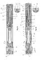
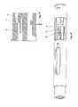
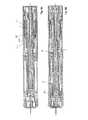
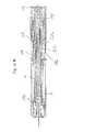
- FIGS. 1 and 2show a concept structure of a first embodiment of an injection device according to the invention.
- the injection devicecomprises a sleeve-shaped housing 2, on which a syringe holder 1, a mechanism holder 5 and an end cap 12 are fixed to the housing, that is, they are immovable with respect to the housing 2.
- the syringe holder 1, the mechanism holder 5 and the end cap 12may be latched, glued, 29weiselt, locked or snapped with the housing 2 or may be formed integrally with the housing 2 in each case or in total.
- a preferably pre-filled syringe 13can be received and held by this.
- the syringe 13has a limited by a along the longitudinal axis of the syringe 13 slidable plug 13 a Aufuahmeraum 13 b, in which a substance to be dispensed is, which by displacement of the plug 13 a in the distal longitudinal direction of the syringe 13 (in Fig. 1 displaced to the left) out of this space and can be delivered by a arranged on the front of the syringe 13 needle 14 in a known manner.
- the needle 14is in Fig. 1 shown initial state surrounded by a needle cap 15, in which a z. B. elastic or made of rubber needle protection element 15 a is present.
- the needle cap 15can be deducted together with the rubber element 15a contained therein by means of the attached thereon Kappenabzugselements 4 to expose the needle 14, which in the initial position shown also from the front of an axial Direction of the housing 2 insertable and again extendable needle guard 3 is surrounded.
- injection spring 9is biased and is held in the initial state between the piston rod 7 and the click pin 6, wherein the injection spring 9 is mounted within the piston rod 7 and is surrounded by the piston rod 7 and a distal bottom element 7b of Piston rod 7 presses or is supported against this. In the proximal direction, the injection spring 9 is held by a proximal bottom or plate element 6d of a click-pin 6 or is supported against it.
- the click-pin 6has an axially extending middle web 6e, which is arranged in the inserted state within the injection spring 9 and is connected at the proximal end with the plate member 6d, from which approximately parallel to the central web 6e trigger snaps 6a extend, which are deformable or resilient, so that arranged on each Ausletteschnapparm 6a radially inwardly projecting inner cam 6b and radially outwardly projecting outer cam 6c in the radial direction, ie radially outward or inward can be moved.
- the inner cam 6bengage in recesses or openings 7a of the piston rod 7, so that in this state an axial displacement between click pin 6 and piston rod 7 by the force of the prestressed injection spring 9 is not possible.
- the spring assemblyconsisting of click pin 6, piston rod 7 and injection spring 9 can thus not be pressed apart.
- a radial deflection of the Ausletteschnapparme 6a to the outsideis prevented by the in the region of the outer cam 6c around the click pin 6 arranged axially displaceable locking sleeve 8, the inner side of the outer cam 6c lie against or abut against this.
- the injection spring 9is preferably a compression spring or coil spring, which preferably stores or can absorb at least the energy for a Aus thoroughlysequenz and which is used as the tensioned spring in the injection device.
- the needle protection device 3which is designed as a sleeve-shaped element and is mounted displaceably relative to the housing 2, has on its distal end face a passage opening 3d, through which the needle 14 pass or which moves back in the axial direction along the needle 14 or in the Housing 2 can be inserted.
- Axial directionextending two opposite webs 3a are provided, which are relative to the passage opening 3d in the proximal direction.
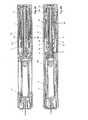
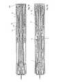
- FIGS. 3A and 3Bare relative to each other by 90 ° offset cross-sectional views of the injection device in the delivery state.
- the injection spring 9is biased between the piston rod 7 and the click pin 6.
- the piston rod 7is held against the force of the injection spring 9, which exerts a force acting on the piston rod 7 in the distal direction force, by the inner cam 6b of the Auslösschnschnme 6 a of the click pin 6, as shown Fig. 3B seen.
- the locking sleeve 8prevents radially outwardly directed movement of the cams 6b and the triggering snaffle 6a.
- An end-click element 11is pressed or held in the proximal direction by a needle protection sleeve spring 10, which presses on an annular radial expansion 11 b of the click element 11.
- the needle protection sleeve spring 10is supported on a flange 8g of the locking sleeve 8.
- the spring 10, like the spring 9,can already be preloaded or relaxed in the injection device.
- the locking sleeve 8is located proximally offset to the webs 3a of the needle guard 3, which is held by radially outwardly engaging in recesses or passages of the webs 3a proximal cam 1a of the housing-fixed syringe holder 1 against displacement in the distal direction.
- the so proximally pressed or held click element 11holds, as in Fig. 3A shown by radially inwardly projecting on spring arms 11 c arranged cams 11 a, which engage in recesses or openings 7 c of the piston rod 7, the piston rod 7 in the proximal starting position shown, in which the distal end face of the piston rod 7 from the proximal rear side of the plug 13 a spaced is.
- the click element 11is in the initial or delivery state with its proximal end face on the plate-shaped bottom 12b of the housing 2 by means of the snapper 12a snapped or fixed to the housing end cap 12.
- the syringe 13 inserted into the injection deviceis in the syringe holder 1 by means of a shoulder support 1b or radially inwardly projecting protrusions 1b of the syringe holder. 1 held forward and secured in the housing 2 by means of a ring or a housing taper 2b. This ring or the housing taper 2b prevents radial deflection of the syringe holder 1b.
- the syringe holder 1is located on the front side on radially inwardly projecting ribs or projections 2e of the housing 2.
- Fig. 3C - 3Gshow an internal development of 180 °, ie one half, the locking sleeve 8, wherein radially inwardly projecting portions are shown hatched. The positions of the locking sleeve 8 in connection with the movements of the needle guard 3 are explained.
- the locking sleeveis shown in the initial state of the needle guard.
- the lying between the hatched areas guide areas or grooves of the locking sleeve 8allow engagement of a radially outwardly directed cam 6c of the click pin 6.
- the locking sleeve 8can be moved in the position shown in the axial direction.
- the needle 14Before starting to use the injection device, the needle 14 must be exposed, for which purpose the cap withdrawal element 4 is removed in the distal direction from the distal front side of the injection device. How out Fig. 3A can be seen, snap the snap hooks 4a of the cap withdrawal element 4 behind the rear edge of the needle cap 15 a. Provided on the radially outer side of the snap hooks 4a provided on these ribs 2f of the housing 2 prevents dodging of this snap hook 4a, so that by pulling on the cap withdrawal element 4, the needle cap 15 can be removed in the distal direction. In this case, the attached within the needle cap 15 elastic or Kunststoffnadelschutz 15a is withdrawn together with the needle cap 15, so that the needle 14 is exposed.
- the cap withdrawal element 4is held on the needle protection sleeve 3 by means of a snap element 4b, which engages behind a radially projecting snap holder 3b.
- a forcehas to be expended that can overcome the snap holder 3b, 4b.
- the needle 14After removal of the cap withdrawal element 4 together with the needle cap 15, the needle 14 is exposed, but is still surrounded by the distal sleeve portion of the needle guard 3, which also extends in the distal direction beyond the tip of the needle 14, so that the needle 14 through the front or distal part of the needle guard 3 is still protected.
- the usernormally shifts it onto the housing 2 from a user holding the housing 2 Applied pressure the needle guard 3 in the proximal axial direction into the housing 2, whereby the relative to the housing 2 fixed needle 14 is exposed and inserted into the puncture site.
- FIGS. 4A and 4BThis state is in the offset by 90 ° to each other offset cross-sectional views of FIGS. 4A and 4B shown.
- the needle protection sleeve 3is inserted with the pressure exerted on the housing 2 in the distal direction by the contact area surrounding the support surface in the housing 2 to the insertion of the needle guard 3 limiting stop 2c, which takes place at the same time with the insertion of the needle 14 into the injection site.
- the radially outwardly projecting cam 6c lying on an elastic triggering snare 6a of the click pin 6is in the in FIG Fig. 3C shown starting position still outside a guide portion on the radially inner side of the locking sleeve 8 and is moved relative to the housing 2 in an engagement region only after the puncture in the axial direction relative to the locking sleeve 8 by an axial displacement of the locking sleeve 8, as in Fig. 3D and in Fig. 4D shown in which the cam 6c rests with a frontal bevel in the axial direction of a chamfer 8b of the web 8h. Because in this state, a distal direction (in Fig.
- the automatic injectionis triggered.
- the locking sleeve 8is axially displaced so far in the proximal direction by the adjacent webs 3a of the needle guard 3 within the housing 2 that the trigger snapper 6a the click pins 6 are released by the no longer around the outer cam 6c and wegverschobene locking sleeve 8, thereby the Ausl Harborschnapparme 6a can escape radially outward.
- the corresponding radially outwardly depressed trigger snaffle 6a of the click-pin 6are in Fig. 5B shown.
- the piston rod 7is released and can, driven by the force of the prestressed injection spring 9, move relative to the housing 2 within the housing 2 in the distal direction on the plug 13a.
- the click pin 6is released and pressed axially by the force of the injection spring 9 within the housing 2 in the proximal direction until the proximal end face of the pin 6 strikes the distal bottom surface of the end cap 12, as in FIGS FIGS. 5A and 5B shown.
- the impact of the click pin 6 on the end cap 12generates a start signal or start click.
- damping elementscan be attached, whereby the attack or impact of the click pin 6 can be delayed or slowed down and so the start signal can be modified.
- a crush rib 12c and a counter rib 12c 'which is applied at an angle relative to the crush rib 12c attached.
- additional damping tabs or latches 12d and opposing damping ribs 12d 'may be provided.
- FIGS. 5A and 5Bshow 90 ° offset from each other cross-sectional views of the injection device after the start-click, which signals the beginning of the injection acoustically and tactilely, and the activation of the signal described below to indicate the end of injection (End-Of-Injection Click).
- the piston rod 7is moved in the distal direction by the force of the relaxing injection spring 9 and comes into abutment against the plug 13 a, on which the piston rod 7 exerts a force acting in the distal direction by the proximally supporting injection spring 9, whereby the plug 13 a in the syringe 13 is inserted, so as in the To dispense syringe 13 contained substance which is delivered or injected through the pierced needle 14.
- the piston rod 7is, as in Fig. 4A shown before moving to hitting the proximal side of the plug 13a still connected to the click element 11 by means of the cam 11a, which engage in corresponding recesses or recesses of the piston rod 7. This engagement is secured by the mechanism bracket 5, which tends to dislodge the click-claw arms 11c, and prevents the click-element arms 11c from dodging radially outward and thus releasing the engagement with the piston rod 7. If the piston rod 7 has been displaced so far in the distal direction that outer cam 11d of the click element arms 11c can engage in escape openings of the mechanism holder 5, as in FIG Fig.
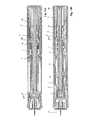
- FIGS. 6A and 6Bshow 90 ° offset from one another longitudinal cross-sectional views of the injection device after pouring the substance.
- the no longer retained piston rod 7was inserted by the force of the injection spring 9 in the syringe 13, whereby the plug 13a was moved in the distal direction until it is present at the end of the glass body and the substance was thus completely released or discharged.
- the click element 11is moved in the proximal direction after release by the Nadelschutzhülsenfeder 10 until it abuts the bottom 12 b of the end cap 12 and causes a final click.
- This final clickis audible and tactile by a user to signal the end of the injection. The final click is therefore not effected by the injection spring 9.
- FIGS. 7A and 7Bshow 90 ° offset from one another longitudinal cross-sectional views of the injection device at or after completion of the final click. If the injection device removed after the discharge from the injection site, the needle guard 3 moves together with the pressing on them locking sleeve 8, which are both acted upon by the Nadeltikhülsenfeder 10 in the distal direction with a force to the front, ie relative to the housing 2 axially in the distal direction.
- a provided on a respective web 3a of the needle guard 3 centering cam 3cengages in this state in a centering 8e of the locking sleeve 8 and thus prevents the Verriegeluzagshülse 8 can be turned back.
- the needle protection sleeve 3is pushed out beyond the needle 14 and secured against being pushed back by the cam 5c which is in contact with the step 8f of the locking track 8c.
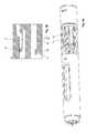
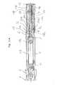
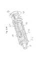
- FIG. 8shows an exploded view of a second embodiment of an injection device.
- the Figures 9A and 9Bshow 90 ° offset from one another longitudinal cross-sectional views in the delivery state.
- the injection spring 9is biased between the piston rod 7 and end cap 12.
- a release sleeve 16is located forward on ribs 16c on the mechanism holder 5.
- the mechanism holder 5 and the end cap 12are firmly connected.
- the piston rod 7is held in the distal direction by a release snapper 16 a of the release sleeve 16 and secured by means of the locking sleeve 8.
- a cam 5c of the mechanism holder 5is engaged with an axially extending groove 8a of the locking sleeve 8 and prevents the locking sleeve 8 from rotating relative to the mechanism holder 5.
- the Nadelschutzhülsenfeder 10is biased between the locking sleeve 8 and the release sleeve 16.
- the mechanism holder 5 and the end cap 12are fixed to the housing and z. B. connected by snapping or snapping with the housing 2.
- the locking sleeve 8rests on webs or tabs 3 a of the needle guard 3, which is held forward on a cam 1 a on the syringe holder 1.
- the release sleeve 16is held to the rear over the secured by the locking sleeve 8 release arms 16a of the release sleeve 16 on the piston rod 7.
- the syringe 13is secured as described in the first embodiment by means of a shoulder pad 1b and by means of a ring or a housing taper 2b.
- the decrease in the needle cap 4is also carried out as described in the first embodiment.
- Figures 10A and 10Bshow 90 ° to each other rotated longitudinal cross-sectional views of the injection device in the inserted state when the injection device is pressed onto the injection site.
- the needle guard 3is pressed to the stop 2c in the housing 2 while the needle 14 is inserted into the injection site.
- the Needle protection sleeve 3moves the locking sleeve 8 relative to the mechanism holder 5 and the release sleeve 16, whereby the Nadeltikbülsenfeder 10 is compressed or compressed.
- the injectionis triggered by the complete insertion of the needle guard 3 into the housing 2.
- the locking sleeve 8relative to the housing 2, the mechanism holder 5 and the release sleeve 16 in the proximal direction (in Fig. 10 to the right), releasing the tripping buttons 16a.
- the release snapper 16aare pressed and released against the movement of the piston rod 7 in the distal direction forward.
- the release sleeve 16is now held over the snapper 16b on the mechanism holder 5 to the rear.
- FIGS 11A and 11Bshow 90 ° offset from one another longitudinal cross-sectional views of the injection device after dumping and after clicking to signal the end of injection (End-Of-Injection Click).
- the piston rod 7has been moved by the force of the injection spring 9 in the distal direction, wherein the piston rod 7 presses on the plug 13 a and this moves in the distal direction until it is present at the end of the glass body of the syringe 13.
- the piston rod 7has at its proximal end a slot 7b, whereby the arms 16b of the release sleeve 16 are released at the end of the injection and the blocking of the release sleeve 16 is released to the rear.
- the needle protection lockis carried out in the same manner as described in the first embodiment, wherein the deflected release arms are arranged on the release sleeve 16 and not the click pin 6, so reference is made in this regard to the above description.
- the Figures 12A and 12Bshow 90 ° offset from one another longitudinal cross-sectional views of a third embodiment of an injection device in the delivery state.
- the injection spring 9is biased between the piston rod 7 and the release sleeve 16.
- the Release sleeve 16is held by the arms 16b on the mechanism holder 5 and secured by means of the piston rod 7.
- the piston rod 7is held forward by the tripping snapper 16a and secured by the locking sleeve 8.
- the cam 5c of the mechanism holder 5is in engagement with the axially extending groove 8a of the locking sleeve 8 and prevents the locking sleeve 8 from rotating relative to the housing-fixed mechanism holder 5.
- the needle guard sleeve spring 10is biased between the locking sleeve 8 and the mechanism holder 5.
- the mechanism holder 5is snapped with the housing 2.
- the locking sleeve 8rests on the tabs 3a of the needle guard 3, which is held forward on the cam 1a on the syringe holder 1.
- the syringe 13is mounted in the syringe holder 1 and the housing 2 as described in the above embodiments.
- FIGS. 13A and 13Bshow 90 ° staggered longitudinal cross-sectional views of the injection device, which has been pressed onto the injection site, the contents of the syringe was dispensed and a signalization of the end of the injection is done.
- the needle 14is inserted.
- the needle protection sleeve 3is pressed into the housing 2 up to the stop 2c.
- the needle guard 3moves the locking sleeve 8 relative to the mechanism holder 5 and the release sleeve 16, wherein the needle guard sleeve spring 10 is compressed.
- the injectionis triggered by the complete insertion of the needle guard 3 into the housing 2.
- the locking sleeve 8is displaced relative to the housing 2, the mechanism holder 5 and the release sleeve 16 in the proximal direction, wherein the Ausl Harborschnapper 16a are released.
- the tripping snapper 16aare pressed and released against the movement of the piston rod 7 forward.
- the piston rod 7has been moved in the distal direction, wherein the piston rod 7 presses on the plug 13 a and this far moved in the distal direction until it is present at the end of the glass body of the syringe 13.
- the piston rod 7has at its proximal end a slot 7e, whereby the arms 16b of the release sleeve 16 are released at the end of the injection and the blocking of the release sleeve 16 in the proximal direction or to the rear is canceled.
- the release sleeve 16is moved by the force of the injection spring 9 in the proximal direction and abuts the bottom 5b of the mechanism holder 5 and the final click caused.
- the needle protection lockis carried out in the same manner as described in the second embodiment.
- Fig. 14Ashows a longitudinal cross-sectional view of another embodiment of an injection device in the delivery state, in which the injection spring 9 rests at its distal end on the inside of the piston rod 7. At its proximal end, the injection spring 9 abuts against a housing-fixed holding sleeve 18, which surrounds a click-pin 20 and engages radially at a proximal location with engagement arms 18c through openings of the piston rod 7 in this.
- the click-pin 20 provided for generating the end-clickis moved in the proximal direction (in FIG. 13) via a syringe spring 19, which presses on distal end faces of click-pin arms 20a Fig.
- the syringe spring 19is supported in the proximal direction on the arms 20a of the click-pin 20 and presses in the distal direction on the syringe 13, to store them safely in the syringe holder 1 by the thus generated acting in the distal direction pressure.
- the arms 20a of the click-pin 20are by means of radially inwardly projecting cams 20b in engagement with openings 7a of the piston rod 7 and can be taken in a distally directed movement of the piston rod 7, so that the piston rod 7 in a distal movement of the in Fig. 14A
- the click pin 20initially takes. A release of the retaining connection 7a, 20b by radially deflecting the arms 20a is prevented by the retaining pin 18 surrounding the click pin 20.
- a release sleeve 22is displaced by the adjacent webs 3a of the needle guard 3 against the force of Nadeltikhülsenfeder 10 within the housing 2 axially in the proximal direction far enough that a holding element of the holding sleeve 18, which engages in the piston rod 7, is released.
- the now released piston rod 7can be moved in the distal direction on the plug 13 a of the syringe 13 and insert this plug 13 a in the syringe 13 to so to make the payout.
- the click pin 20is carried along by the piston rod 7 until the arms 20a of the click pin in the release 18a of the holding sleeve 18 can deflect radially and by this engagement of the radially on the arms 20a outer cam 20c on the holding sleeve 18th being held.
- a radially inwardly directed deflection of the arms 20a of the click-pin 20is so long by the voltage applied to the inside of the cam 20b piston rod 7 until the piston rod 7 has been moved so far in the distal direction that the full distribution has been made.
- the arms 20a of the click-pin 20can dodge radially inward because the piston rod 7 has been moved so far in the distal direction that, either according to an embodiment not shown, the piston rod has already completely moved past the cam 20b or, as in FIG Fig. 14B shown, the inner cam 20 b in openings or exemptions on the piston rod 7 can steer back.
- the click pin 20is thus no longer held by cams 20c or 20b and accelerated in the proximal direction by the biased syringe spring 19 to abut on the retainer sleeve 18 or alternatively on the end cap 12 (not shown) and thus end-click noise to create.
- Fig. 15Ashows a further embodiment of a functional unit for generating an end click.
- an injection spring between the piston rod 7 and a stabilizing pin or the holding sleeve 18is biased to torsion.
- the stabilization pinrests on the bottom of the holding sleeve 18 and extends axially within the injection spring and is secured with the holding sleeve 18 against rotation.
- the piston rod 7is linearly guided by means of a linear guide element 7f in the holding sleeve 18 in a linear guide 18b.
- the piston rod 7After injection by axially forwardly pushing out the piston rod 7 from the holding sleeve 18, as in Fig. 15B shown, the piston rod 7 is decoupled by the retraction of the linear guide element 7f from the linear guide 18b.
- the piston rod 7By means of the torsional moment of the injection spring 9, the piston rod 7 is rotated in the direction defined by the arrow D indicating the direction of rotation and beaten in the circumferential direction against the retaining sleeve 18 or a linear guide groove inner surface with a stop element 7h, whereby an end click can be generated.
- the piston rod 7can rotate on the plug 13a of the syringe 13.
- Fig. 16Ashows another embodiment of a functional unit for generating a Endticians, wherein the energy for the final click is provided by the Nadeltikhülsenfeder 10.
- the Nadeltikhülsenfeder 10is between the in Fig. 16A Prolonged sleeve 22 and the click sleeve 21 biased.
- the click sleeve 21has hooks 21 a, which engage in the holding sleeve 18.
- the piston rod 7has a cam 7g, which towards the end of the injection, as in Fig. 16B shown by passing from proximal to distal (in Fig. 16B from right to left) the hooks 21a of the click sleeve 21 is pressed, whereby they unhook from the holding sleeve 18 and so the coupling of the click sleeve 21 is released with the holding sleeve 18.
- the click sleeve 21is accelerated or moved by the Nadelschutzhülsenfeder 10 to the rear or in the proximal direction to a stop on the retaining sleeve 18, whereby the final click is generated.
Landscapes
- Health & Medical Sciences (AREA)
- Vascular Medicine (AREA)
- Engineering & Computer Science (AREA)
- Anesthesiology (AREA)
- Biomedical Technology (AREA)
- Heart & Thoracic Surgery (AREA)
- Hematology (AREA)
- Life Sciences & Earth Sciences (AREA)
- Animal Behavior & Ethology (AREA)
- General Health & Medical Sciences (AREA)
- Public Health (AREA)
- Veterinary Medicine (AREA)
- Infusion, Injection, And Reservoir Apparatuses (AREA)
Abstract
Translated fromGerman
Description
Translated fromGermanDie Erfindung betrifft eine Substanzabgabevorrichtung, insbesondere eine Injektionsvorrichtung oder einen Autoinjektor, die eine Signalisierungsvorrichtung aufweist, um z. B. optisch, akustisch und/oder taktil anzuzeigen, wann eine Abgabe einer Substanz oder eine Ausschüttung vollständig oder mindestens zu einem vorgegebenen Teil erfolgt ist. Eine z. B. automatisch ausschüttbare Substanz kann ein fluides Produkt oder Medikament sein, welches z. B. flüssig, pastenartig oder gelartig ist.The invention relates to a substance delivery device, in particular an injection device or an autoinjector, which has a signaling device to z. B. optically, acoustically and / or tactile to indicate when a delivery of a substance or a distribution is complete or at least to a predetermined part. A z. B. automatically ausschüttbare substance may be a fluid product or drug, which z. B. is liquid, paste-like or gel-like.
Aus der
Die
Die
Es ist eine Aufgabe der Erfindung eine Substanzabgabevorrichtung oder Injektionsvorrichtung bereitzustellen, bei welcher der Anwender auf einfache Art eine Injektion auslösen und durch die Vorrichtung über den korrekten Funktionsablauf informiert werden kann.It is an object of the invention to provide a substance delivery device or injection device in which the user can easily initiate an injection and be informed by the device about the correct operation.
Diese Aufgabe wird gelöst durch die Vorrichtung gemäß Anspruch 1 und das Verfahren gemäß Anspruch 11. Vorteilhafte Weiterentwicklungen sind in den abhängigen Ansprüchen definiert.This object is achieved by the device according to
Eine erfindungsgemäße Vorrichtung zum Verabreichen einer Substanz ist vorzugsweise eine Autoinjektionsvorrichtung, welche ein Energiespeicher- oder Antriebselement aufweist, mit welchem die Ausschüttung automatisch durchgeführt werden kann. Dabei ist vorzugsweise keine extern z. B. von einem Benutzer zuzuführende oder aufzuwendende Kraft oder Energie erforderlich. Das Energiespeicher- oder Antriebselement speichert vorteilhaft die vollständige für eine automatische Substanzabgabe erforderliche Energie. Ein solches Energiespeicher- oder Antriebselement kann beispielsweise eine Feder sein. Diese Feder kann in einem energiespeiehernden Zustand, also z. B. komprimiert, auseinandergezogen oder auch verdreht, in die Injektionsvorrichtung eingebaut werden und durch einen Energieabgabevorgang, also z. B. durch Entspannen, wenn die Feder komprimiert oder verdreht bzw. auf Torsion beansprucht eingebaut wurde, oder auch durch Zusammenziehen, wenn die Feder auseinandergezogen eingebaut wurde, Energie abgeben. Die Energieabgabe erfolgt vorteilhaft unmittelbar oder mittelbar, d. h. über zwischengeschaltete Bauelemente, an eine Kolbenstange oder ein Druckelement, welches auf einen Stopfen einer Spritze drückt und diesen Stopfen in die Spritze einschieben kann.A device according to the invention for administering a substance is preferably an autoinjection device which has an energy storage or drive element with which the distribution can be carried out automatically. In this case, preferably no external z. B. required by a user to be supplied or expended force or energy. The energy storage or drive element advantageously stores the complete energy required for automatic substance delivery. Such an energy storage or drive element may for example be a spring. This spring can be in a energetic state, ie z. B. compressed, pulled apart or twisted, are installed in the injection device and by an energy delivery process, ie z. B. by relaxing when the spring is compressed or twisted or torsion claimed installed, or by contracting, when the spring was installed exploded, give energy. The energy release is advantageously carried out directly or indirectly, d. H. via intermediate components, to a piston rod or a pressure element which presses on a plug of a syringe and can push this plug into the syringe.
Optional kann das Energiespeicherelement oder ein weiteres separates Energiespeicherelement vorgesehen sein, um auch den Vorgang des Einstechens einer Nadel zu automatisieren. Der Einstechvorgang kann jedoch auch manuell erfolgen, also z. B. durch einen Benutzer vorgenommen werden, ohne hierfür in der Injektionsvorrichtung gespeicherte Energie zu verwenden.Optionally, the energy storage element or a further separate energy storage element may be provided to automate the process of insertion of a needle. However, the plunge process can also be done manually, ie z. B. be made by a user without using this stored energy in the injection device.
Die Verabreichungsvorrichtung weist ein Abgabeelement, z. B. eine Nadel, auf, durch welches die Substanz abgegeben werden kann. Die Nadel ist auf bekannte Art mit dem Behältnis für die abzugebende Substanz gekoppelt, sodass z. B. beim Verschieben des oben erwähnten Stopfens die Substanz durch die Nadel hindurchtritt und am distalen vorderen Ende der Substanz abgegeben und injiziert wird.The administering device has a delivery element, e.g. As a needle, through which the substance can be discharged. The needle is coupled in a known manner with the container for the substance to be dispensed, so z. B. when moving the above-mentioned plug, the substance passes through the needle and is discharged and injected at the distal front end of the substance.
Für das Abgabeelement ist ein Schutzelement vorgesehen, beispielsweise eine über das Abgabeelement hinauszuschiebende Hülse, welche beispielsweise parallel zur Längsrichtung einer als Abgabeelement dienenden Nadel axial verschoben werden kann. Das Schutzelement kann vor der Abgabe das Abgabeelement z. B. radial umgeben und auch distal über das Abgabeelement hinausragen, so dass das Abgabeelement im Wesentlichen oder vollständig durch das Schutzelement umgeben oder bedeckt wird. Dabei weist das Schutzelement vorteilhaft eine Durchtrittsöffnung für das Abgabeelement auf, durch welche das Abgabeelement den Schutzbereich des Schutzelements verlassen kann. Es kann sowohl das Abgabeelement aktiv durch das Schutzelement hindurchbewegt werden als auch das Schutzelement aktiv von dem Abgabeelement entfernt, also z. B. in proximale Richtung zurückgeschoben, werden, um zumindest den distalen Bereich des Abgabeelements freizugeben.A protective element is provided for the dispensing element, for example a sleeve which is to be pushed over the dispensing element and which can be axially displaced, for example, parallel to the longitudinal direction of a needle serving as a dispensing element. The protective element may, prior to delivery, the delivery element z. B. radially surround and also protrude distally over the dispensing element, so that the dispensing element is substantially or completely surrounded or covered by the protective element. In this case, the protective element advantageously has a passage opening for the dispensing element, through which the dispensing element can leave the protective area of the protective element. Both the dispensing element can be actively moved through the protective element and the protective element can be actively removed from the dispensing element, ie, for example. B. pushed back in the proximal direction, to release at least the distal region of the dispensing element.
Das Schutzelement ist mit einem Antriebselement gekoppelt, welches separat von den oben erwähnten optional vorgesehenen Antriebselementen ausgebildet sein kann oder ausgebildet ist, z. B. als eine zweite oder dritte Antriebsfeder innerhalb einer Injektionsvorrichtung. Mit diesem Antriebselement kann das Schutzelement angetrieben werden. Z. B. kann das Antriebselement bewirken, dass das Schutzelement nach erfolgter Substanzabgabe wieder über das Abgabeelement gebracht oder geschoben werden kann. Optional kann das Antriebselement auch als Halteelement dienen, z. B. um das Schutzelement vor und/oder nach einer Substanzabgabe in einer Schutzstellung über oder um das Abgabeelement zu halten. Das Antriebselement kann in einem entspannten Zustand oder in einem gespannten oder geladenen, also Energie beinhaltenden oder speichernden, Zustand in der Injektionsvorrichtung eingebaut sein, wobei diese Energie zum Antreiben des Schutzelements dienen kann. Wird das Antriebselement in einem Zustand in der Injektionsvorrichtung eingebaut, in welchem dieses keine oder wenig Energie speichert, so muss das Antriebselement während eines Funktionsablaufes vor dem Antreiben des Schutzelements von einem anderen Element mit Energie versorgt werden, also z. B. von einem Benutzer oder einem der erwähnten weiteren Antriebselemente, z. B. einer gespannten Ausschüttfeder.The protective element is coupled to a drive element which may be formed or formed separately from the above-mentioned optionally provided drive elements, for. B. as a second or third drive spring within an injection device. With this drive element, the protective element can be driven. For example, the drive element can cause the protective element can be brought back or pushed over the dispensing element after substance delivery. Optionally, the drive element can also serve as a holding element, for. B. to hold the protective element before and / or after a substance delivery in a protective position over or around the dispensing element. The drive element can be installed in a relaxed state or in a charged or charged, ie energy-containing or storing, state in the injection device, which energy can be used to drive the protective element. If the drive element is installed in a state in the injection device in which this stores little or no energy, the drive element must during a functional sequence before driving the protective element be powered by another element with energy, so z. B. by a user or one of the mentioned further drive elements, for. B. a tensioned discharge spring.
Eine Rückkopplungsvorrichtung der Injektionsvorrichtung kann ein Signal erzeugen, wenn eine vorgegebene oder die gesamte Menge der abzugebenden Substanz abgegeben wurde. Das erzeugte Signal kann ein akustisches Signal sein, also z. B. ein "Klick"-Geräusch, welches erzeugt wird, wenn ein sich bewegendes Element an einem anderen anschlägt. Ebenso ist es möglich, dass das akustische Signal ein z. B. mechanisch erzeugtes Reibungs- oder Kratzgeräusch ist, wenn zwei Elemente relativ zueinander bewegt werden. Das Signal kann auch ein taktiles oder haptisches Signal sein, also ein Signal, welches von einem Benutzer erfüllt werden kann. Ein solches Signal kann z. B. ebenfalls durch einen Anschlag eines Elements an einem anderen Element erzeugt werden oder ein Rüttel- oder Reibungssignal sein, wenn sich zwei Elemente relativ zueinander bewegen. Weiterhin kann das Signal ein optisches Signal sein, wie z. B. ein Farbsignal oder ein Farbbereich der Rückkopplungsvorrichtung, welcher z. B. in einen bestimmten Bereich verschoben wird. Beispielsweise kann die Rückkopplungsvorrichtung eine Signalfarbe tragen, welche aus einem sichtbaren Bereich herausbewegt wird oder in einen sichtbaren Bereich hineinbewegt wird, um anzuzeigen, dass eine Substanzabgabe noch nicht erfolgt oder auch abgeschlossen ist.A feedback device of the injection device may generate a signal when a predetermined or the entire amount of the substance to be dispensed has been delivered. The generated signal may be an acoustic signal, so z. As a "click" sound, which is generated when a moving element abuts another. It is also possible that the acoustic signal z. B. mechanically generated friction or scratching noise when two elements are moved relative to each other. The signal can also be a tactile or haptic signal, ie a signal which can be fulfilled by a user. Such a signal can, for. B. also be generated by a stop of an element on another element or be a vibration or friction signal when two elements move relative to each other. Furthermore, the signal may be an optical signal, such. B. a color signal or a color range of the feedback device, which z. B. is moved to a specific area. For example, the feedback device may carry a signal color that is moved out of a visible area or moved into a visible area to indicate that a substance delivery has not yet occurred or is completed.
Erfindungsgemäß ist die Rückkopplungsvorrichtung mit dem Antriebselement gekoppelt, mit welchem auch das Schutzelement gekoppelt ist. Beispielsweise ist die Rückkopplungsvorrichtung ein Anschlagelement, also ein Pin oder eine Hülse, welche von einer Nadelschutzhülsenfeder beschleunigt oder gegen einen Anschlag bewegt wird, wobei die Nadelschutzhülsenfeder ein Nadelschutzelement mit Druck beaufschlagt oder Kraft auf dieses ausübt, um das Nadelschutzelement relativ zum Abgabeelement oder zur Nadel in eine Schutzposition zu bringen oder zu halten.According to the invention, the feedback device is coupled to the drive element with which the protective element is also coupled. For example, the feedback device is a stop element, ie a pin or sleeve, which is accelerated by a Nadelschutzhülsenfeder or moved against a stop, the Nadelschutzhülsenfeder a needle protection element with pressure or force exerted on the needle protection element relative to the delivery element or the needle in to bring or hold a protective position.
Das Rückkopplungselement kann z. B. an dem Gehäuse der Injektionsvorrichtung anschlagen, ist also relativ zu diesem bewegbar, wobei es auch möglich ist, dass das Rückkopplungselement an jedem anderen Teil anschlägt. Vorzugsweise wird das Rückkopplungselement von dem erwähnten Antriebselement über eine vorgegebene Strecke z. B. geradlinig oder in einer Drehbewegung beschleunigt, um mit einer bestimmten Geschwindigkeit einen Aufschlag und somit ein bemerkbares Rückkopplungssignal zu erzeugen.The feedback element may, for. B. to the housing of the injection device, so it is movable relative to this, wherein it is also possible that the feedback element abuts on every other part. Preferably, the feedback element of the mentioned drive element over a predetermined distance z. B. straight or in one Speeds up rotational movement to produce a surcharge and thus a noticeable feedback signal at a certain speed.
Die erfindungsgemäße Vorrichtung kann eine weitere separate zweite Rückkopplungsvorrichtung aufweisen, welche z. B. den Beginn der Substanzabgabe signalisiert. Es ist denkbar, dass beide Rückkopplungsvorrichtungen auch in einem Element realisiert werden können.The device according to the invention may comprise a further separate second feedback device, which z. B. signaled the beginning of the substance delivery. It is conceivable that both feedback devices can also be realized in one element.
Wie bereits erwähnt, kann die Verabreichungsvorrichtung auch ein zweites, drittes, viertes oder weiteres Antriebselement oder Energiespeicherelement aufweisen, welches z. B. Energie zur Bewirkung der Substanzabgabe und/oder Energie zur Durchführung eines Nadeleinstichs zur Verfügung stellt. Dieses zweite oder weitere Antriebselement ist separat von dem Antriebselement vorgesehen, welches mit der Rückkopplungsvorrichtung gekoppelt ist und kann z. B. funktional vollständig von dem Rückkopplungs-Antriebselement getrennt sein. Ebenso ist es möglich, dass ein solches weiteres Antriebselement Energie an das Rückkopplungs-Antriebselement abgibt oder überträgt.As already mentioned, the administering device can also have a second, third, fourth or further drive element or energy storage element which, for. B. energy for effecting the substance delivery and / or energy for performing a Nadeleinstichs provides. This second or further drive element is provided separately from the drive element, which is coupled to the feedback device and can, for. B. functionally be completely separated from the feedback drive element. It is also possible that such a further drive element emits or transmits energy to the feedback drive element.
An dem Rückkopplungselement kann auch ein Modulations- oder Dämpfungselement vorgesehen sein, mittels welchem die Rückkopplung, also z. B. ein Rückkopplungsgeräusch oder ein taktiles Rückkopplungssignal, beeinflusst oder modifiziert werden kann. Beispielsweise können Laschen oder Anschlagflächen oder Dämpfungsmittel vorgesehen sein, welche einen Aufprall oder Aufschlag der Rückkopplungsvorrichtung auf einer Fläche oder einem Aufschlagsteil verzögern oder abbremsen. Ebenso ist es möglich, dass ein Modulationselement die Anschlagsfläche vergrößert, um die zu erzeugende Signalstärke zu vergrößern.At the feedback element and a modulation or damping element may be provided by means of which the feedback, ie, for. As a feedback noise or a tactile feedback signal, can be influenced or modified. For example, tabs or stop surfaces or damping means may be provided which delay or decelerate an impact or impact of the feedback device on a surface or impact member. It is also possible that a modulation element increases the stop area in order to increase the signal strength to be generated.
Das Rückkopplungselement kann vorzugsweise von einer lösbaren Haltevorrichtung bis zum Ende der Substanzabgabe gehalten werden, sodass beispielsweise das Rückkopplungselement erst dann freigegeben oder ausgelöst und z. B. erst dann von einem Antriebselement angetrieben wird, wenn die Substanzabgabe vollständig oder bis zu einem gewissen vorher definierten Grad erfolgt ist, also z. B. die Kolbenstange bis zu einem festgelegten Ausschüttpunkt verschoben wurde.The feedback element may preferably be held by a releasable holding device until the end of the substance delivery, so that, for example, the feedback element only then released or triggered and z. B. is then driven by a drive element when the substance delivery is complete or to a certain degree previously defined, ie z. B. the piston rod has been moved to a specified Ausschüttpunkt.
Die Rückkopplungsvorrichtung kann, wie oben erwähnt, ein Anschlagselement sein, welches z. B. entlang einer geraden Strecke beschleunigt oder angetrieben wird, um am Ende an einem Anschlagsort aufzutreffen und so ein Rückkopplungssignal zu erzeugen. Ebenso ist es möglich, dass die Rückkopplungsvorrichtung beispielsweise ein Drehelement ist, welches z. B. nach der festgestellten Beendigung der vollständigen Substanzabgabe eine Drehbewegung ausführt und einen Drehanschlag erzeugt. Hierfür kann z. B. ein Torsionsmoment einer verwendeten Feder, also z. B. einer verwendeten Nadelschutzfeder oder auch einer Injektionsfeder, verwendet werden.The feedback device may, as mentioned above, be a stop element which z. B. is accelerated or driven along a straight line to end up at a stop location and so to generate a feedback signal. It is also possible that the feedback device is for example a rotary element, which z. B. after the detected completion of the complete substance delivery rotates and generates a rotation stop. For this purpose, z. B. a torsional moment of a spring used, ie z. As a used needle shield spring or an injection spring, are used.
Gemäß einem weiteren Aspekt bezieht sich die Erfindung auf ein Verfahren zum Abgeben einer Substanz aus einer wie oben beschriebenen Vorrichtung, wobei die Substanz mittels eines ersten Antriebselements automatisch abgegeben wird und ein Rückkopplungssignal zur Signalisierung der z. B. beendeten Substanzabgabe mittels eines von einem separaten zweiten Antriebselements angetriebenen Rückkopplungselements erzeugt wird. Die Antriebselemente sind folglich separate Vorrichtungen oder Funktionseinheiten, also beispielsweise zwei getrennt vorgesehene Federn, welche jedoch miteinander gekoppelt werden können, um Energie von einer Feder, also z. B. von einer Antriebsfeder, auf eine andere Feder, also z. B. die Rückkopplungsfeder, zu übertragen.According to a further aspect, the invention relates to a method for dispensing a substance from a device as described above, wherein the substance is emitted automatically by means of a first drive element and a feedback signal for signaling the z. B. ended substance delivery is generated by means of a driven by a separate second drive element feedback element. The drive elements are therefore separate devices or functional units, so for example two separately provided springs, which, however, can be coupled together to energy from a spring, ie, for. B. from a drive spring, to another spring, ie z. B. the feedback spring to transfer.
Diese Energie- oder Kraftübertragung kann vor, während oder nach der Substanzabgabe erfolgen.This energy or power transmission can take place before, during or after the substance delivery.
Die Erfindung wird anhand mehrerer beispielhafter Ausführungsfbrmen beschrieben. Es zeigen:
- Fig.1
- eine Querschnittsansicht entlang einer Längsachse einer ersten Ausführungsform einer Injektionsvorrichtung zur Veranschaulichung des Konzeptaufbaus;
- Fig. 2
- eine Explosionsansicht der in
Fig. 1 gezeigten Injektionsvorrichtung; - Fig. 3A und 3B
- um 90° zueinander gedrehte Querschnittsansichten der Injektionsvorrichtung im Auslieferungszustand;
- Fig. 3C bis 3G
- Abwicklung der radialen Innenseite der Verriegelungshülse (180° Abwicklung) zur Veranschaulichung der Relativbewegung der eingreifenden Nocken des Mechanikhalters und des Klick Pins
- Fig. 4A und 4B
- um 90° gedrehte Querschnittsansichten der Injektionsvorrichtung im eingestochenen Zustand, wenn die Injektionsvorrichtung auf die Injektionsstelle gedrückt wird oder wurde;
- Fig. 4D bis 4H
- Detailansicht der Verriegelungshülse und das Prinzip der Nadelschutzverriegelung zur Veranschaulichung der Relativbewegung der eingreifenden Nocken des Mechanikhalters und des Klick Pins
- Fig. 5A und 5B
- um 90° zueinander gedrehte Querschnittsansichten der Injektionsvorrichtung vor dem Beginn der Ausschüttung;
- Fig. 6A und 6B
- um 90° zueinander versetzte Querschnittsansichten der Injektionsvorrichtung nach erfolgter Ausschüttung;
- Fig. 7A und 7B
- um 90° zueinander versetzte Querschnittsansichten der Injektionsvorrichtung nach erfolgter Ausschüttung und diese erfolgte Ausschüttung bestätigenden Anschlag eines Klick-Elements;
- Fig. 8
- eine Explosionsansicht einer zweiten Ausführungsform einer Injektionsvorrichtung
- Fig. 9A und 9B
- um 90° zueinander gedrehte Querschnittsansichten der Injektionsvorrichtung im Auslieferungszustand;
- Fig. 10A und 10B
- um 90° zueinander versetzte Längsquerschnittsansichten der Injektionsvorrichtung im eingestochenen Zustand, wenn die Injektionsvorrichiung auf die Injektionsstelle gedrückt wurde;
- Fig. 11A und 11B
- um 90° zueinander versetzte Querschnittsansichten der Injektionsvorrichtung nach erfolgter Ausschüttung und erfolger Signalisierung des Endes der Injektion durch Anschlag der Freigabehülse an der Endkappe;
- Fig. 12A und 12B
- eine um 90° zueinander gedrehte Querschnittsansichten einer dritten Ausführungsform einer Injektionsvorrichtung im Auslieferungszustand;
- Fig. 13A und 13B
- um 90° zueinander versetzte Querschnittsansichten der Injektionsvorrichtung nach erfolgter Einstech- und Ausschüttbewegung und Bestätigung der vollständigen Ausschüttung durch Anschlag der Freigabehülse am Boden des Mechanikhalters.
- Fig. 14A
- zeigt eine weitere Ausführungsform einer Injektionsvorrichtung im Auslieferungszustand, bei welcher die Spritzenfeder die Energie für den Endklick (End-of-Injection-Klick) zur Verfügung stellt;
- Fig. 14B
- zeigt die Injektionsvorrichtung gemäß
Fig. 14A im ausgeschütteten Zustand vor dem Endklick; - Fig. 15A
- zeigt eine weitere Ausführungsform einer End-Klick-Einheit im Auslieferungszustand, bei welcher ein rotativer Anschlag durch ein Torsionsmoment der Injektionsfeder erzeugt wird;
- Fig. 15B
- zeigt die Funktionseinheit von
Fig. 15A bei erzeugtem Endklick; - Fig. 16A
- zeigt eine weitere Ausführungsform einer Funktionseinheit im Auslieferungszustand zur Erzeugung eines Endklicks durch die Energie der Nadelschutzhülsenfeder;
- Fig. 16B
- zeigt die Funktionseinheit von
Fig. 16A nach erfolgtem Endklick.
- Fig.1
- a cross-sectional view along a longitudinal axis of a first embodiment of an injection device to illustrate the concept structure;
- Fig. 2
- an exploded view of in
Fig. 1 shown injection device; - FIGS. 3A and 3B
- Cross-sectional views of the injection device rotated by 90 ° relative to one another in the delivery state;
- Fig. 3C to 3G
- Processing of the radial inside of the locking sleeve (180 ° unwinding) to illustrate the relative movement of the engaging cams of the mechanism holder and the click pin
- FIGS. 4A and 4B
- 90 ° rotated cross-sectional views of the injection device in the inserted state when the injection device is pressed or was on the injection site;
- 4D to 4H
- Detail view of the locking sleeve and the principle of the needle protection lock to illustrate the relative movement of the engaging cams of the mechanism holder and the click pin
- Figs. 5A and 5B
- Cross-sectional views of the injection device rotated by 90 ° relative to each other before the beginning of the discharge;
- FIGS. 6A and 6B
- 90 ° offset from one another cross-sectional views of the injection device after disbursement;
- Figs. 7A and 7B
- Cross-sectional views, offset by 90 °, of the injection device after the discharge has taken place and this distribution has been confirmed by a click element;
- Fig. 8
- an exploded view of a second embodiment of an injection device
- Figs. 9A and 9B
- Cross-sectional views of the injection device rotated by 90 ° relative to one another in the delivery state;
- Figs. 10A and 10B
- 90 ° staggered longitudinal cross-sectional views of the injection device in the inserted state when the Injektionsvorrichiung was pressed onto the injection site;
- Figs. 11A and 11B
- 90 ° offset from each other cross-sectional views of the injection device after disbursement and sucess signaling the end of the injection by abutment of the release sleeve on the end cap;
- Figs. 12A and 12B
- a 90 ° to each other rotated cross-sectional views of a third embodiment of an injection device in the delivery state;
- Figs. 13A and 13B
- By 90 ° mutually offset cross-sectional views of the injection device after the insertion and ejection movement and confirmation of the full distribution by stopping the release sleeve at the bottom of the mechanism holder.
- Fig. 14A
- shows a further embodiment of an injection device in the delivery state, in which the syringe spring provides the energy for the end-of-the-click (End-of-Injection-Click);
- Fig. 14B
- shows the injection device according to
Fig. 14A in the distributed state before the final click; - Fig. 15A
- shows a further embodiment of an end-click unit in the delivery state, in which a rotary stop is generated by a torsional moment of the injection spring;
- Fig. 15B
- shows the functional unit of
Fig. 15A when endclick is generated; - Fig. 16A
- shows a further embodiment of a functional unit in the delivery state for generating a Endklicks by the energy of the Nadelschutzhülfederfeder;
- Fig. 16B
- shows the functional unit of
Fig. 16A after the final click.
Die
Eine als Energiespeicher oder Antriebsmittel dienende Injektionsfeder 9 ist vorgespannt und wird im Ausgangszustand zwischen der Kolbenstange 7 und dem Klick-Pin 6 gehalten, wobei die Injektionsfeder 9 innerhalb der Kolbenstange 7 gelagert ist und von der Kolbenstange 7 umgeben wird und auf ein distales Bodenelement 7b der Kolbenstange 7 drückt bzw. sich gegen dieses abstützt. In proximaler Richtung wird die Injektionsfeder 9 von einem proximalen Boden- oder Tellerelement 6d eines Klick-Pins 6 gehalten bzw. stützt sich gegen dieses ab. Der Klick-Pin 6 weist einen in axialer Richtung verlaufenden Mittelsteg 6e auf, welcher im eingesetzten Zustand innerhalb der Injektionsfeder 9 angeordnet ist und am proximalen Ende mit dem Tellerelement 6d verbunden ist, von welchem sich in etwa parallel verlaufend zum Mittelsteg 6e Auslöseschnapparme 6a erstrecken, welche verformbar oder federnd ausgebildet sind, so dass die an jedem Auslöseschnapparm 6a angeordneten radial nach innen vorstehenden Innennocken 6b und radial nach außen vorstehenden Außennocken 6c in radialer Richtung, also radial nach außen oder innen bewegt werden können. Die Innennocken 6b greifen in Vertiefungen oder Öffnungen 7a der Kolbenstange 7 ein, so dass in diesem Zustand eine axiale Verschiebung zwischen Klick-Pin 6 und Kolbenstange 7 durch die Kraft der vorgespannten Injektionsfeder 9 nicht möglich ist. Das aus Klick-Pin 6, Kolbenstange 7 und Injektionsfeder 9 bestehende Federpaket kann somit nicht auseinander gedrückt werden. Ein radiales Ausweichen der Auslöseschnapparme 6a nach außen wird durch die im Bereich der Außennocken 6c um den Klick-Pin 6 herum angeordneten axial verschiebbare Verriegelungshülse 8 verhindert, deren Innenseite die Außennocken 6c gegenüberliegen oder an dieser anliegen.A serving as energy storage or drive means
Die Injektionsfeder 9 ist vorzugsweise eine Druckfeder oder Wendelfeder, welche bevorzugt mindestens die Energie für eine Ausschüttsequenz speichert oder aufnehmen kann und welche als so gespannte Feder in die Injektionsvorrichtung eingesetzt wird.The
Die Nadelschutzeinrichtung 3, welche als hülsenförmiges Element ausgebildet ist und relativ zum Gehäuse 2 verschiebbar gelagert ist, weist an ihrer distalen Stirnseite eine Durchtrittsöffnung 3d auf, durch welche die Nadel 14 hindurchtreten bzw. welche in axialer Richtung entlang der Nadel 14 zurück bewegt oder in das Gehäuse 2 eingeschoben werden kann. In axialer Richtung sich erstreckend sind zwei gegenüberliegende Stege 3a vorgesehen, welche sich relativ zur Durchtrittsöffnung 3d in proximaler Richtung befinden.The
Die
Ein End-Klick-Element 11 wird durch eine Nadelschutzhülsenfeder 10, welche auf eine ringförmige radiale Aufweitung 11b des Klick-Elements 11 drückt, in proximale Richtung gedrückt bzw. gehalten. An der gegenüberliegenden Seite stützt sich die Nadelschutzhülsenfeder 10 an einem Flansch 8g der Verriegelungshülse 8 ab. Die Feder 10 kann ebenso wie die Feder 9 bereits vorgespannt oder auch entspannt in die Injektionsvorrichtung eingesetzt werden. Die Verriegelungshülse 8 liegt proximal versetzt an den Stegen 3a der Nadelschutzhülse 3 an, welche über radial nach außen stehende in Ausnehmungen oder Durchgänge der Stege 3a eingreifende proximale Nocken 1a des gehäusefesten Spritzenhalters 1 gegen eine Verschiebung in distale Richtung gehalten wird.An end-
Das so nach proximal gedrückte oder gehaltene Klick-Element 11 hält, wie in
Das Klick-Element 11 liegt im Ausgangs- oder Auslieferzustand mit seiner proximalen Stirnfläche auf dem tellerförmigen Boden 12b der mit dem Gehäuse 2 mittels der Schnapper 12a verschnappten oder gehäusefesten Endkappe 12 auf.The
Die in die Injektionsvorrichtung eingesetzte Spritze 13 wird im Spritzenhalter 1 mittels einer Schulterauflage 1b oder radial nach innen vorstehenden Vorsprüngen 1b des Spritzenhalters 1 nach vorne gehalten und mittels eines Ringes oder einer Gehäuseverjüngung 2b im Gehäuse 2 gesichert. Dieser Ring bzw. die Gehäuseverjüngung 2b verhindert ein radiales Ausweichen der Spritzenhalterung 1b. Der Spritzenhalter 1 liegt stirnseitig auf radial nach innen vorstehenden Rippen oder Vorsprüngen 2e des Gehäuses 2 auf.The
Radial nach außen vorstehende Nocken 1c auf Federarmen 1d des gehäusefesten Spritzenhalters 1 greifen in eine axial verlaufende Nut 3e eines jeden Stegs 3a der Nadelschutzhülse 3 ein und sind von dem oben erwähnten radial vorstehenden Nocken 1a in axialer Richtung so weit wie etwa die Länge der axialen Nut 3e beabstandet, so dass die Nadelschutzhülse 3 durch die in die axiale Nut 3e eingreifenden axial voneinander beabstandeten Nocken 1a und 1c gegen axiale Verschiebung gehalten wird, wobei die auf den Federarmen 1d vorgesehenen Nocken 1c bei Anliegen einer relativ kleinen Eindrückkraft an der Nadelschutzhülse 3 radial nach innen ausweichen und ein proximales Einschieben der Nadelschutzhülse 3 in das Gehäuse ermöglichen.Radially outwardly projecting
Die
In der
Vor Beginn der Benutzung der Injektionsvorrichtung muss die Nadel 14 freigelegt werden, wozu das Kappenabzugselement 4 in distaler Richtung von der distalen Vorderseite der Injektionsvorrichtung abgezogen wird. Wie aus
Nach Abnahme des Kappenabzugselements 4 zusammen mit der Nadelschutzkappe 15 liegt die Nadel 14 frei, wird jedoch noch von dem distalen Hülsenbereich der Nadelschutzhülse 3 umgeben, welcher auch in distale Richtung über die Spitze der Nadel 14 hinausragt, so dass die Nadel 14 durch den vorderen oder distalen Teil der Nadelschutzhülse 3 noch geschützt wird.After removal of the
Wird die sich nach dem Abnehmen des Kappenabzugselements 4 im einsatzbereiten Zustand befindliche Injektionsvorrichtung mit ihrer distalen Stirnseite, also dem distalen vorderen Bereich der Nadelschutzhülse 3, auf eine Einstichstelle aufgedrückt, so verschiebt sich durch diesen üblicherweise von einem das Gehäuse 2 haltenden Benutzer auf das Gehäuse 2 aufgebrachten Druck die Nadelschutzhülse 3 in proximaler axialer Richtung in das Gehäuse 2 hinein, wodurch die relativ zum Gehäuse 2 feststehende Nadel 14 freigelegt und in die Einstichstelle eingestochen wird.If the injection device located in the ready-for-use state after removal of the
Dieser Zustand ist in den um 90° zueinander gedreht versetzten Querschnittsansichten der
Durch das Einschieben der Nadelschutzhülse 3 wird die, wie in
Der auf einem elastischen Auslöseschnapparm 6a des Klickpins 6 liegende radial nach außen ragende Nocken 6c ist in der in
Wird das Gehäuse 2 der Injektionsvorrichtung soweit auf die Injektionsstelle gedrückt, dass die Nadelschutzhülse 3 fast vollständig oder vollständig in das Gehäuse 2 eingeschoben worden ist, wie in
Die entsprechend radial nach außen gedrückten Auslöseschnapparme 6a des Klick-Pins 6 sind in
Wie bereits beschrieben wird durch das Aufdrücken der Auslösearme 6a die Nadelschutzverriegelung aktiviert (
Die
Die Kolbenstange 7 wird durch die Kraft der sich entspannenden Injektionsfeder 9 in distale Richtung bewegt und gerät in Anlage an den Stopfen 13a, auf welchem die Kolbenstange 7 durch die sich proximal abstützende Injektionsfeder 9 eine in distale Richtung wirkende Kraft ausübt, wodurch der Stopfen 13a in die Spritze 13 eingeschoben wird, um so die in der Spritze 13 enthaltene Substanz zu verdrängen, welche durch die eingestochene Nadel 14 abgeben oder injiziert wird.The
Die Kolbenstange 7 ist, wie in
Die
Die eine radial nach innen gerichtete Bewegung der Nocken 11a auf den Klickelementarmen 11c verhindernde Kolbenstange 7, welche an den Innennocken 11c des Klickelements 11 in dem in den
Die
Durch die Kraft der Nadelschutzhülsenfeder 10 wird die Verriegelungshülse 8 in distale Richtung (in
Ein an einem jeweiligen Steg 3a der Nadelschutzhülse 3 vorgesehener Zentriernocken 3c greift in diesem Zustand in eine Zentriernut 8e der Verriegelungshülse 8 ein und verhindert somit, dass die Verriegeluzagshülse 8 zurückgedreht werden kann. Somit ist in diesem Zustand die Nadelschutzhülse 3 über die Nadel 14 hinaus ausgeschoben und gegen ein Zurückschieben durch den an der Stufe 8f der Verriegelungsbahn 8c anstehenden Nocken 5c gesichert.A provided on a
Die
Die Nadelschutzhülsenfeder 10 ist zwischen der Verriegelungshülse 8 und der Freigabehülse 16 vorgespannt. Der Mechanikhalter 5 und die Endkappe 12 sind gehäusefest und z. B. durch Verschnappen oder Einrasten mit dem Gehäuse 2 verbunden.The
Die Verriegelungshülse 8 liegt auf Stegen oder Laschen 3a der Nadelschutzhülse 3 auf, welche nach vorne über einen Nocken 1a auf dem Spritzenhalter 1 gehalten wird. Die Freigabehülse 16 wird nach hinten über die von der Verriegelungshülse 8 gesicherten Auslösearme 16a der Freigabehülse 16 an der Kolbenstange 7 gehalten.The locking
Die Spritze 13 wird ebenso wie in der ersten Ausführungsform beschrieben mittels einer Schulterauflage 1b und mittels eines Ringes bzw. einer Gehäuseverjüngung 2b gesichert.The
Die Abnahme der Nadelschutzkappe 4 erfolgt ebenfalls wie im ersten Ausführungsbeispiel beschrieben.The decrease in the
Die Injektion wird durch das vollständige Einschieben der Nadelschutzhülse 3 in das Gehäuse 2 ausgelöst. Dabei wird die Verriegelungshülse 8 relativ zum Gehäuse 2, zum Mechanikhalter 5 und zur Freigabehülse 16 in proximale Richtung (in
Die
Sobald die Arme 16b der Freigabehülse 16 durch den Schlitz 7b der Kolbenstange 7 freigegeben sind, werden die Arme 16b ausgelenkt, wobei die Freigabehülse 16 durch die Kraft der Nadelschutzhülsenfeder 10 nach hinten bewegt wird und an dem Boden 12c der Endkappe 12 anschlägt und den Endklick verursacht.Once the
Die Nadelschutzverriegelung erfolgt auf gleiche Art wie im ersten Ausführungsbeispiel beschrieben, wobei die ausgelenkten Auslösearme an der Freigabehülse 16 und nicht am Klick-Pin 6 angeordnet sind, so dass diesbezüglich auf obige Beschreibung verwiesen wird.The needle protection lock is carried out in the same manner as described in the first embodiment, wherein the deflected release arms are arranged on the
Die
Die Nadelschutzhülsenfeder 10 ist zwischen der Verriegelungshülse 8 und dem Mechanikhalter 5 vorgespannt. Der Mechanikhalter 5 ist mit dem Gehäuse 2 verschnappt. Die Verriegelungshülse 8 liegt auf den Laschen 3a der Nadelschutzhülse 3 auf, welche nach vorne über den Nocken 1a auf dem Spritzenhalter 1 gehalten wird.The needle
Die Spritze 13 wird wie in den obigen Ausführungsformen beschrieben im Spritzenhalter 1 und Gehäuse 2 gelagert.The
Das Abnehmen des Kappenabzugselements 4 zum Abnehmen der Nadelschutzkappe 15 erfolgt wie oben beschrieben.The removal of the
Die
Zunächst wird die Nadel 14 eingestochen. Dabei wird die Nadelschutzhülse 3 bis auf den Anschlag 2c in das Gehäuse 2 eingedrückt. Die Nadelschutzhülse 3 verschiebt die Verriegelungshülse 8 relativ zum Mechanikhalter 5 und zur Freigabehülse 16, wobei die Nadelschutzhülsenfeder 10 gestaucht wird.First, the
Die Injektion wird durch das vollständige Einschieben der Nadelschutzhülse 3 in das Gehäuse 2 ausgelöst. Dabei wird die Verriegelungshülse 8 relativ zum Gehäuse 2, zum Mechanikhalter 5 und zur Freigabehülse 16 in proximale Richtung verschoben, wobei die Auslöseschnapper 16a freigegeben werden. Durch die Kraft der Injektionsfeder 9 werden die Auslöseschnapper 16a aufgedrückt und gegen die Bewegung der Kolbenstange 7 nach vorne frei.The injection is triggered by the complete insertion of the
Durch die Kraft der Injektionsfeder 9 ist die Kolbenstange 7 in distale Richtung bewegt worden, wobei die Kolbenstange 7 auf den Stopfen 13a drückt und diesen soweit in distale Richtung bewegt bis dieser am Ende des Glaskörpers der Spritze 13 ansteht. Die Kolbenstange 7 weist an ihrem proximalen Ende einen Schlitz 7e auf, wodurch die Arme 16b der Freigabehülse 16 am Ende der Injektion freigegeben werden und die Sperrung der Freigabehülse 16 in proximale Richtung bzw. nach hinten aufgehoben wird.By the force of the
Sobald die Arme 16b der Freigabehülse 16 durch den Schlitz 7e der Kolbenstange 7 freigegeben sind, werden die Arme 16b ausgelenkt, wobei die Freigabehülse 16 durch die Kraft der Injektionsfeder 9 in proximale Richtung bewegt wird und an dem Boden 5b des Mechanikhalters 5 anschlägt und den Endklick verursacht.Once the
Die Nadelschutzverriegelung erfolgt auf gleiche Art wie im zweiten Ausführungsbeispiel beschrieben.The needle protection lock is carried out in the same manner as described in the second embodiment.
Wird das Gehäuse 2 der Injektionsvorrichtung so weit auf eine Injektionsstelle gedrückt, dass die Nadelschutzhülse 3 fast vollständig oder vollständig in das Gehäuse 2 eingeschoben worden ist, wie in
Dabei wird eine Auslösehülse 22 durch die anliegenden Stege 3a der Nadelschutzhülse 3 gegen die Kraft der Nadelschutzhülsenfeder 10 innerhalb des Gehäuses 2 axial in proximale Richtung soweit verschoben, dass ein Halteelement der Haltehülse 18, welches eingreift in die Kolbenstange 7, freigegeben wird.In this case, a
Da die Kolbenstange 7 durch die Injektionsfeder 9 in distale Richtung relativ zum Gehäuse 2 mit einer Kraft beaufschlagt ist, kann die nun freigegebene Kolbenstange 7 in distale Richtung auf den Stopfen 13a der Spritze 13 bewegt werden und diesen Stopfen 13a in die Spritze 13 einschieben, um so die Ausschüttung durchzuführen. Während der Ausschüttung wird der Klick-Pin 20 durch die Kolbenstange 7 mitgenommen, bis die Arme 20a des Klick-Pins in der Freistellung 18a der Haltehülse 18 radial auslenken können und durch diesen Eingriff der radial an den Armen 20a außenliegenden Nocken 20c an der Haltehülse 18 gehalten werden. Ein radial nach innen gerichtetes Ausweichen der Arme 20a des Klick-Pins 20 ist durch die innen an den Nocken 20b anliegende Kolbenstange 7 so lange unmöglich, bis die Kolbenstange 7 soweit in distale Richtung bewegt wurde, dass die vollständige Ausschüttung erfolgt ist.Since the
Am Ende der Ausschüttung können die Arme 20a des Klick-Pins 20 radial nach innen ausweichen, da die Kolbenstange 7 soweit in distale Richtung bewegt wurde, dass entweder gemäß einer nicht gezeigten Ausführungsform die Kolbenstange schon vollständig an den Nocken 20b vorbeibewegt wurde oder, wie in
Die Kolbenstange 7 ist mittels einer Linearführungselements 7f in der Haltehülse 18 in einer Linearführung 18b linear geführt.The
Nach erfolgter Injektion durch axial nach vorne gerichtetes Ausschieben der Kolbenstange 7 aus der Haltehülse 18, wie in
Dabei kann optional auch die Kolbenstange 7 auf dem Stopfen 13a der Spritze 13 drehen.Optionally, the
Die Kolbenstange 7 weist einen Nocken 7g auf, welcher gegen Ende der Injektion, wie in
Die Klick-Hülse 21 wird durch die Nadelschutzhülsenfeder 10 nach hinten bzw. in proximale Richtung zu einem Anschlag auf der Haltehülse 18 beschleunigt oder bewegt, wodurch der End-Klick erzeugt wird.The
Claims (12)
Translated fromGermanPriority Applications (20)
| Application Number | Priority Date | Filing Date | Title |
|---|---|---|---|
| EP13160614.7AEP2781230B2 (en) | 2013-03-22 | 2013-03-22 | Substance dispensing device with a signaling device |
| EP19188038.4AEP3590568A1 (en) | 2013-03-22 | 2013-03-22 | Substance dispensing device with a signalling device |
| PL13178676TPL2742962T3 (en) | 2013-03-22 | 2013-07-31 | Autoinjector with a signalling device at the end of the product dispensing |
| EP13178676.6AEP2742962B1 (en) | 2013-03-22 | 2013-07-31 | Autoinjector with a signalling device at the end of the product dispensing |
| EP19211679.6AEP3650064A1 (en) | 2013-03-22 | 2013-07-31 | Autoinjector with a signalling device at the end of the product dispensation |
| ES13178676TES2773850T3 (en) | 2013-03-22 | 2013-07-31 | Autoinjector with signaling equipment at the end of the product distribution |
| EP20202491.5AEP3797812A1 (en) | 2013-03-22 | 2013-07-31 | Autoinjector with syringe holder and protective needle sleeve |
| DK13178676.6TDK2742962T3 (en) | 2013-03-22 | 2013-07-31 | Auto-injector with a signaling device at the end of the product discharge |
| JP2016503502AJP6294458B2 (en) | 2013-03-22 | 2014-03-20 | Substance release device with signaling device |
| CN201480017265.0ACN105246528B (en) | 2013-03-22 | 2014-03-20 | Automatic injection device with signaling mechanism |
| PCT/CH2014/000035WO2014146210A1 (en) | 2013-03-22 | 2014-03-20 | Autoinjector with a signalling device |
| PCT/CH2014/000034WO2014146209A1 (en) | 2013-03-22 | 2014-03-20 | Substance dispensing device with signalling device |
| JP2016503503AJP6154061B2 (en) | 2013-03-22 | 2014-03-20 | Automatic syringe with signaling device |
| US14/858,755US10569019B2 (en) | 2013-03-22 | 2015-09-18 | Substance dispensing device with signaling device |
| US14/858,790US10350356B2 (en) | 2013-03-22 | 2015-09-18 | Autoinjector with a signaling device |
| US16/438,865US10881799B2 (en) | 2013-03-22 | 2019-06-12 | Autoinjector with a signaling device |
| US16/736,905US11607494B2 (en) | 2013-03-22 | 2020-01-08 | Substance dispensing device with signaling device |
| US17/105,117US11944789B2 (en) | 2013-03-22 | 2020-11-25 | Autoinjector with a signaling device |
| US18/171,479US20230277770A1 (en) | 2013-03-22 | 2023-02-20 | Substance dispensing device with signaling device |
| US18/590,386US20240198000A1 (en) | 2013-03-22 | 2024-02-28 | Autoinjector with a signaling device |
Applications Claiming Priority (1)
| Application Number | Priority Date | Filing Date | Title |
|---|---|---|---|
| EP13160614.7AEP2781230B2 (en) | 2013-03-22 | 2013-03-22 | Substance dispensing device with a signaling device |
Related Child Applications (2)
| Application Number | Title | Priority Date | Filing Date |
|---|---|---|---|
| EP19188038.4ADivision-IntoEP3590568A1 (en) | 2013-03-22 | 2013-03-22 | Substance dispensing device with a signalling device |
| EP19188038.4ADivisionEP3590568A1 (en) | 2013-03-22 | 2013-03-22 | Substance dispensing device with a signalling device |
Publications (3)
| Publication Number | Publication Date |
|---|---|
| EP2781230A1true EP2781230A1 (en) | 2014-09-24 |
| EP2781230B1 EP2781230B1 (en) | 2019-08-21 |
| EP2781230B2 EP2781230B2 (en) | 2025-05-14 |
Family
ID=47915551
Family Applications (5)
| Application Number | Title | Priority Date | Filing Date |
|---|---|---|---|
| EP19188038.4AWithdrawnEP3590568A1 (en) | 2013-03-22 | 2013-03-22 | Substance dispensing device with a signalling device |
| EP13160614.7AActiveEP2781230B2 (en) | 2013-03-22 | 2013-03-22 | Substance dispensing device with a signaling device |
| EP13178676.6AActiveEP2742962B1 (en) | 2013-03-22 | 2013-07-31 | Autoinjector with a signalling device at the end of the product dispensing |
| EP20202491.5APendingEP3797812A1 (en) | 2013-03-22 | 2013-07-31 | Autoinjector with syringe holder and protective needle sleeve |
| EP19211679.6APendingEP3650064A1 (en) | 2013-03-22 | 2013-07-31 | Autoinjector with a signalling device at the end of the product dispensation |
Family Applications Before (1)
| Application Number | Title | Priority Date | Filing Date |
|---|---|---|---|
| EP19188038.4AWithdrawnEP3590568A1 (en) | 2013-03-22 | 2013-03-22 | Substance dispensing device with a signalling device |
Family Applications After (3)
| Application Number | Title | Priority Date | Filing Date |
|---|---|---|---|
| EP13178676.6AActiveEP2742962B1 (en) | 2013-03-22 | 2013-07-31 | Autoinjector with a signalling device at the end of the product dispensing |
| EP20202491.5APendingEP3797812A1 (en) | 2013-03-22 | 2013-07-31 | Autoinjector with syringe holder and protective needle sleeve |
| EP19211679.6APendingEP3650064A1 (en) | 2013-03-22 | 2013-07-31 | Autoinjector with a signalling device at the end of the product dispensation |
Country Status (8)
| Country | Link |
|---|---|
| US (7) | US10350356B2 (en) |
| EP (5) | EP3590568A1 (en) |
| JP (2) | JP6154061B2 (en) |
| CN (1) | CN105246528B (en) |
| DK (1) | DK2742962T3 (en) |
| ES (1) | ES2773850T3 (en) |
| PL (1) | PL2742962T3 (en) |
| WO (2) | WO2014146210A1 (en) |
Cited By (10)
| Publication number | Priority date | Publication date | Assignee | Title |
|---|---|---|---|---|
| WO2018064784A1 (en) | 2016-10-03 | 2018-04-12 | Tecpharma Licensing Ag | Electronic module for monitoring injection devices |
| WO2018085952A1 (en) | 2016-11-09 | 2018-05-17 | Tecpharma Licensing Ag | Electronic add-on module for injection appliances |
| EP3381493A1 (en) | 2017-03-30 | 2018-10-03 | Tecpharma Licensing AG | Electronic unit for injection devices |
| WO2019043549A1 (en) | 2017-08-31 | 2019-03-07 | Tecpharma Licensing Ag | DRIVE DEVICE FOR INJECTION DEVICES |
| EP2781230B1 (en) | 2013-03-22 | 2019-08-21 | TecPharma Licensing AG | Substance dispensing device with a signaling device |
| EP3545992A1 (en) | 2018-03-29 | 2019-10-02 | Tecpharma Licensing AG | State estimation for drug delivery systems |
| EP3626288A1 (en) | 2018-09-19 | 2020-03-25 | Tecpharma Licensing AG | Electronic add-on module for injectors |
| US12102808B2 (en) | 2019-09-30 | 2024-10-01 | Amgen Inc. | Drug delivery device |
| US12208245B2 (en) | 2019-09-30 | 2025-01-28 | Amgen Inc. | Drug delivery device |
| US12440624B2 (en) | 2018-09-19 | 2025-10-14 | Ypsomed Ag | Electronic add-on module for injection devices |
Families Citing this family (98)
| Publication number | Priority date | Publication date | Assignee | Title |
|---|---|---|---|---|
| DK2536452T3 (en) | 2010-02-18 | 2019-01-02 | Sanofi Aventis Deutschland | autoinjector |
| EP2399635A1 (en) | 2010-06-28 | 2011-12-28 | Sanofi-Aventis Deutschland GmbH | Auto-injector |
| EP2468330A1 (en) | 2010-12-21 | 2012-06-27 | Sanofi-Aventis Deutschland GmbH | Auto-injector |
| EP2489385A1 (en) | 2011-02-18 | 2012-08-22 | Sanofi-Aventis Deutschland GmbH | Auto-injector |
| EP2572741A1 (en) | 2011-09-23 | 2013-03-27 | Sanofi-Aventis Deutschland GmbH | Medicament delivery device and actuation mechanism for a drug delivery device |
| EP2601992A1 (en) | 2011-12-08 | 2013-06-12 | Sanofi-Aventis Deutschland GmbH | Syringe carrier |
| EP2719414A1 (en) | 2012-10-15 | 2014-04-16 | Sanofi-Aventis Deutschland GmbH | Medicament delivery device with use indicator |
| EP2777684A1 (en) | 2013-03-14 | 2014-09-17 | Sanofi-Aventis Deutschland GmbH | Medicament container carrier and adapter |
| CN105188807B (en)* | 2013-03-25 | 2017-12-15 | 卡贝欧洲有限公司 | Drug delivery device including locking mechanism |
| EP2823841A1 (en)* | 2013-07-09 | 2015-01-14 | Sanofi-Aventis Deutschland GmbH | Autoinjector |
| PL2745866T3 (en) | 2014-01-30 | 2017-04-28 | Tecpharma Licensing Ag | Release safety device for an auto-injector |
| EP2923714A1 (en) | 2014-03-28 | 2015-09-30 | Sanofi-Aventis Deutschland GmbH | Autoinjector triggered by skin contact |
| MX388536B (en) | 2014-05-07 | 2025-03-20 | Amgen Inc | AUTO-INJECTOR WITH SHOCK-REDUCING ELEMENTS. |
| CH707898A2 (en) | 2014-07-29 | 2014-10-15 | Tecpharma Licensing Ag | Autoinjector with adjustable dose. |
| US10576213B2 (en)* | 2014-11-04 | 2020-03-03 | Shl Medical Ag | Autoinjector with delayed signal of complete medication delivery |
| IL295010B1 (en) | 2015-03-10 | 2025-06-01 | Regeneron Pharma | Pollution-free piercing system and method |
| CN106139325B (en)* | 2015-04-01 | 2020-06-26 | 群康生技股份有限公司 | injection pen |
| CN106139322A (en)* | 2015-04-01 | 2016-11-23 | 群康生技股份有限公司 | Locking structure of injection pen |
| TW201709940A (en) | 2015-06-03 | 2017-03-16 | 賽諾菲阿凡提斯德意志有限公司 | Sound indicator (1) |
| TW201707737A (en) | 2015-06-03 | 2017-03-01 | 賽諾菲阿凡提斯德意志有限公司 | Drug delivery device (1) |
| TW201709941A (en) | 2015-06-03 | 2017-03-16 | 賽諾菲阿凡提斯德意志有限公司 | Sound indicator (2) |
| TW201707738A (en) | 2015-06-03 | 2017-03-01 | 賽諾菲阿凡提斯德意志有限公司 | Syringe holder and autoinjector (2) |
| TW201707744A (en) | 2015-06-03 | 2017-03-01 | 賽諾菲阿凡提斯德意志有限公司 | Drug delivery device (2) |
| TW201707740A (en) | 2015-06-03 | 2017-03-01 | 賽諾菲阿凡提斯德意志有限公司 | Drug delivery device |
| TW201700117A (en) | 2015-06-03 | 2017-01-01 | 賽諾菲阿凡提斯德意志有限公司 | Syringe bracket and assembly method for autoinjector |
| TW201711713A (en) | 2015-06-03 | 2017-04-01 | 賽諾菲阿凡提斯德意志有限公司 | Drug delivery device |
| TW201700118A (en) | 2015-06-03 | 2017-01-01 | 賽諾菲阿凡提斯德意志有限公司 | Drug delivery device (3) |
| CH711240A2 (en) | 2015-06-23 | 2016-12-30 | Tecpharma Licensing Ag | Auto injection device. |
| CN107029317B (en)* | 2015-07-31 | 2020-07-28 | 重庆倍加医疗器械有限公司 | Medicine injector |
| EP3207952A1 (en) | 2016-02-16 | 2017-08-23 | Carebay Europe Ltd. | An automatic feedback mechanism and a medicament delivery device with user feedback capability |
| US20170246395A1 (en)* | 2016-02-29 | 2017-08-31 | Shl Group Ab | Delivery Device |
| US11065390B2 (en) | 2016-02-29 | 2021-07-20 | Shl Medical Ag | Automatic delivery device with end of injection indication device |
| US10265476B2 (en)* | 2016-03-11 | 2019-04-23 | Shl Medical Ag | Two body syringe carrier assembly with dampener |
| US10583255B2 (en)* | 2016-07-27 | 2020-03-10 | Shl Medical Ag | Medicament container assembly for a medicament delivery device |
| CH712753A2 (en) | 2016-07-28 | 2018-01-31 | Tecpharma Licensing Ag | Separating a needle cap from a product container and method of mounting an injection device. |
| CH711142A2 (en) | 2016-09-21 | 2016-11-30 | Tecpharma Licensing Ag | Needle protection cap for injection device. |
| GB201616709D0 (en)* | 2016-09-30 | 2016-11-16 | Owen Mumford Ltd | Injection device |
| WO2018125629A1 (en) | 2016-12-27 | 2018-07-05 | Action Medical Technologies, Llc | Apparatuses and method for injecting medicaments |
| JP7100044B2 (en) | 2017-01-26 | 2022-07-12 | サノフィ-アベンティス・ドイチュラント・ゲゼルシャフト・ミット・ベシュレンクテル・ハフツング | Flexible module for injection devices |
| US10300218B2 (en) | 2017-03-22 | 2019-05-28 | Shl Medical Ag | Safety assembly for a medical delivery device |
| CN119950880A (en) | 2017-05-05 | 2025-05-09 | 里珍纳龙药品有限公司 | Auto-injectors and related methods of use |
| JP7200134B2 (en) | 2017-06-08 | 2023-01-06 | アムジエン・インコーポレーテツド | Torque driven drug delivery device |
| KR101804319B1 (en)* | 2017-07-11 | 2017-12-04 | 천광주 | Slide type writing tools of sealing member having device for preventing dryness |
| CN110753563B (en)* | 2017-07-12 | 2022-05-10 | 艾斯曲尔医疗公司 | Dosing assembly for a medicament delivery device and medicament delivery device comprising such a dosing assembly |
| US11419983B2 (en) | 2017-07-12 | 2022-08-23 | Shl Medical Ag | Transport assembly for a medicament delivery device and a medicament delivery device comprising the same |
| US11357927B2 (en) | 2017-07-12 | 2022-06-14 | Shl Medical Ag | Administration assembly for a medicament delivery device and a medicament delivery device comprising the same |
| US11400232B2 (en) | 2017-11-03 | 2022-08-02 | Sanofi | Drug delivery device |
| US11654246B2 (en) | 2017-11-03 | 2023-05-23 | Sanofi | Drug delivery device |
| EP3727150B1 (en) | 2017-12-18 | 2024-07-24 | Sanofi | Nfc glucometer containing rechargeable battery for independed useage |
| EP3524297A1 (en)* | 2018-02-12 | 2019-08-14 | Sanofi | Injector device |
| CN112188907A (en) | 2018-05-24 | 2021-01-05 | 诺华股份有限公司 | Automatic drug delivery device |
| WO2020014292A1 (en) | 2018-07-10 | 2020-01-16 | Action Medical Technologies, Llc | Apparatuses and method for injecting medicaments |
| WO2020053288A1 (en)* | 2018-09-13 | 2020-03-19 | Novo Nordisk A/S | Shield triggered injection device |
| AU2019344594B2 (en) | 2018-09-20 | 2024-09-26 | Teva Pharmaceuticals International Gmbh | Injection spring for aged prefilled syringe and auto injector |
| USD926975S1 (en)* | 2018-09-27 | 2021-08-03 | Phc Holdings Corporation | Cartridge for medicine injector |
| USD893712S1 (en) | 2019-02-15 | 2020-08-18 | Action Medical Technologies, Llc | Grip for autoinjectors |
| CA3132163A1 (en)* | 2019-03-15 | 2020-09-24 | Eli Lilly And Company | Automatic injection system |
| CN110292683B (en)* | 2019-07-31 | 2023-09-22 | 派格生物医药(苏州)有限公司 | Automatic injection pen with passive trigger |
| USD915580S1 (en)* | 2019-08-21 | 2021-04-06 | RICHBOND Co., Ltd. | Poison or venom remover |
| WO2021067990A1 (en)* | 2019-09-30 | 2021-04-08 | Amgen Inc. | Drug delivery device |
| JP7748364B2 (en) | 2019-09-30 | 2025-10-02 | アムジエン・インコーポレーテツド | Drug Delivery Devices |
| DE102019220296A1 (en)* | 2019-12-19 | 2021-06-24 | Vetter Pharma-Fertigung GmbH & Co. KG | Injection device for injecting a pharmaceutical substance, and injection loading part for such an injection device |
| BR112022013719A2 (en) | 2020-01-13 | 2022-10-11 | Amgen Inc | NEEDLE PROTECTION REMOVALS, DRUG ADMINISTRATION DEVICES AND RELATED METHODS |
| WO2021160540A1 (en) | 2020-02-11 | 2021-08-19 | Ypsomed Ag | Auto-injector comprising a needle protection sleeve |
| CN111150906B (en)* | 2020-02-24 | 2020-09-29 | 苏州恒瑞宏远医疗科技有限公司 | Two-step automatic injection device |
| WO2021170690A1 (en) | 2020-02-25 | 2021-09-02 | Boehringer Ingelheim International Gmbh | Injection device and a reusable part therefor |
| US11065392B1 (en) | 2020-03-25 | 2021-07-20 | Action Medical Technologies, Llc | Apparatuses and methods for injecting medicaments |
| CH717267A2 (en) | 2020-03-30 | 2021-09-30 | Ypsomed Ag | Auto-injector with a multi-chamber product container. |
| CN111450356B (en)* | 2020-05-15 | 2024-10-18 | 宁波睿爱产品设计有限公司 | Automatic injection device |
| US11759576B2 (en) | 2020-06-05 | 2023-09-19 | Action Medical Technologies, Llc | Parenteral injection apparatus |
| US20230390502A1 (en)* | 2020-10-16 | 2023-12-07 | Shandong Wego Prefills Pharmaceutical Packaging Co., Ltd | Automatic syringe |
| TW202237207A (en) | 2020-12-31 | 2022-10-01 | 美商再生元醫藥公司 | Auto-injector and related methods of use |
| CN112755308A (en)* | 2020-12-31 | 2021-05-07 | 阮杰辉 | Multifunctional infusion support for children |
| CN112933346B (en)* | 2021-02-03 | 2022-11-08 | 宁波易舒医疗科技有限公司 | Axial propelling mechanism, automatic injection device and working method of automatic injection device |
| EP4085945A1 (en)* | 2021-05-06 | 2022-11-09 | Ypsomed AG | Autoinjector with improved co2 footprint |
| CN113209422B (en)* | 2021-05-20 | 2022-10-14 | 宁波睿爱产品设计有限公司 | Injection device with sound prompt function |
| CH717352A2 (en) | 2021-06-30 | 2021-10-29 | Ypsomed Ag | Auto-injector with an electronic module. |
| WO2023272716A1 (en)* | 2021-07-02 | 2023-01-05 | 嘉兴森迈医疗科技有限公司 | Autoinjector and actuating assembly thereof |
| WO2023051963A1 (en) | 2021-09-28 | 2023-04-06 | Ypsomed Ag | Administering devices which can communicate via visible light |
| EP4173656A1 (en) | 2021-10-27 | 2023-05-03 | medmix Switzerland AG | Needle guard, drug delivery device and method for manufacturing |
| US20230248724A1 (en)* | 2021-10-29 | 2023-08-10 | Sun Pharmaceutical Industries Limited | Method of Injecting Dihydroergotamine Into The Body |
| USD1007676S1 (en) | 2021-11-16 | 2023-12-12 | Regeneron Pharmaceuticals, Inc. | Wearable autoinjector |
| US20230211085A1 (en) | 2021-12-31 | 2023-07-06 | Alvotech Hf | Autoinjector Housing |
| USD1042803S1 (en) | 2021-12-31 | 2024-09-17 | Alvotech Hf | Autoinjector housing |
| USD1042805S1 (en) | 2022-05-06 | 2024-09-17 | Alvotech Hf | Autoinjector housing |
| WO2024256275A1 (en) | 2023-06-12 | 2024-12-19 | Boehringer Ingelheim International Gmbh | Holding device for dispensing devices for substance dispensing of at least one therapeutically and/or diagnostically effective substance |
| CN116942962B (en)* | 2023-07-28 | 2024-03-08 | 苏州森恩博医疗科技有限公司 | Automatic injection pen |
| EP4275719A3 (en)* | 2023-09-07 | 2024-04-24 | Ypsomed AG | Safety mechanism for an autoinjector |
| EP4548948A1 (en) | 2023-10-31 | 2025-05-07 | Ypsomed AG | Device for administering a fluid substance |
| EP4548947A1 (en) | 2023-10-31 | 2025-05-07 | Ypsomed AG | Device for administering a fluid substance |
| EP4552673A1 (en) | 2023-11-07 | 2025-05-14 | Ypsomed AG | Injection device with reduced amount of parts |
| EP4556035A1 (en)* | 2024-02-05 | 2025-05-21 | Ypsomed AG | Injection device with a reservoir holder sensor |
| US12268858B1 (en) | 2024-03-04 | 2025-04-08 | Genzyme Corporation | Injector device |
| US12274873B1 (en) | 2024-03-04 | 2025-04-15 | Genzyme Corporation | Medicament delivery device |
| US20250276131A1 (en) | 2024-03-04 | 2025-09-04 | Genzyme Corporation | Medicament delivery device |
| US12274874B1 (en)* | 2024-03-04 | 2025-04-15 | Genzyme Corporation | Injector device |
| WO2025202225A1 (en) | 2024-03-26 | 2025-10-02 | F. Hoffmann-La Roche Ag | Syringe surrogate and method of testing an autoinjector |
| EP4623960A1 (en) | 2024-03-26 | 2025-10-01 | Ypsomed AG | Autoinjector for dispensing a liquid product |
Citations (5)
| Publication number | Priority date | Publication date | Assignee | Title |
|---|---|---|---|---|
| WO1994011041A1 (en) | 1992-11-19 | 1994-05-26 | R G S.A.S. Di Rosaria Galli & C. | Disposable auto-injector for prefilled syringes |
| US20100137798A1 (en)* | 2007-03-22 | 2010-06-03 | Ursina Streit | Spring arrangement in an injection device |
| WO2011043714A1 (en)* | 2009-10-08 | 2011-04-14 | Shl Group Ab | Medicament delivery device |
| WO2011123024A1 (en) | 2010-03-31 | 2011-10-06 | Shl Group Ab | Medicament delivery device comprising feedback signalling means |
| WO2013016832A1 (en) | 2011-08-04 | 2013-02-07 | Tecpharma Licensing Ag | Safety arrangement for injection devices |
Family Cites Families (73)
| Publication number | Priority date | Publication date | Assignee | Title |
|---|---|---|---|---|
| US1819258A (en) | 1929-09-28 | 1931-08-18 | Nevin Mendel | Syringe |
| US2591046A (en)* | 1948-10-18 | 1952-04-01 | Frederick M Turnbull | Hypodermic syringe assembly |
| US3144178A (en) | 1962-03-12 | 1964-08-11 | Stanley J Sarnoff | Cartridge holder |
| EP0518416A1 (en) | 1991-06-13 | 1992-12-16 | Duphar International Research B.V | Injection device |
| AU4883797A (en) | 1997-11-03 | 1999-05-24 | Ermanno Greco | Self-injection device |
| JP4339260B2 (en) | 2002-11-25 | 2009-10-07 | テクファーマ・ライセンシング・アクチェンゲゼルシャフト | Injection device with needle protection device |
| CH695926A5 (en) | 2002-11-25 | 2006-10-31 | Tecpharma Licensing Ag | Device for automatically injecting an active ingredient. |
| US6805686B1 (en) | 2003-05-06 | 2004-10-19 | Abbott Laboratories | Autoinjector with extendable needle protector shroud |
| US20050027255A1 (en) | 2003-07-31 | 2005-02-03 | Sid Technologies, Llc | Automatic injector |
| DE10342058B4 (en)* | 2003-09-11 | 2007-10-25 | Tecpharma Licensing Ag | Administration device for an injectable product with a trigger safety device |
| DE10359694A1 (en) | 2003-12-18 | 2005-07-28 | Tecpharma Licensing Ag | Injection unit for self-administration of liquid, comprises a removable element coupled to an energy storage element so that energy is supplied to the latter through removal of the removable element |
| EP1715903B1 (en) | 2004-01-23 | 2007-10-24 | The Medical House Plc | Injection device |
| US20050222539A1 (en)† | 2004-03-30 | 2005-10-06 | Pediamed Pharmaceuticals, Inc. | Automatic injection device |
| GB2414401B (en) | 2004-05-28 | 2009-06-17 | Cilag Ag Int | Injection device |
| US8048035B2 (en)* | 2004-08-06 | 2011-11-01 | Meridian Medical Technologies, Inc. | Automatic injector with needle cover |
| ES2557778T3 (en) | 2004-11-24 | 2016-01-28 | Group Ab Shl | Injection device |
| PL1877119T3 (en)* | 2005-01-25 | 2019-03-29 | Novo Nordisk A/S | An injection device with an end of dose feedback mechanism |
| GB2424838B (en)* | 2005-04-06 | 2011-02-23 | Cilag Ag Int | Injection device (adaptable drive) |
| DE102005063497B4 (en) | 2005-05-24 | 2009-09-24 | Tecpharma Licensing Ag | Plastic spring |
| DE202005010389U1 (en) | 2005-07-01 | 2005-09-08 | Tecpharma Licensing Ag | Injection unit capable of accommodating an ampule incorporates a fixed magnet and a counter-magnet on the movable piston rod of the unit |
| MXPA05014181A (en)* | 2005-12-21 | 2007-06-20 | Roberto Ruiz Diaz | System of fully-adjustable brackets. |
| GB0601309D0 (en)* | 2006-01-23 | 2006-03-01 | Medical House The Plc | Injection device |
| FR2899482A1 (en) | 2006-04-11 | 2007-10-12 | Becton Dickinson France Soc Pa | Automatic medicament/product injection device for patient, has safety shield coupled to housing, and provided in active state at end of needle insertion step before which product/medicament injection step is not started |
| KR101396797B1 (en) | 2006-06-30 | 2014-05-26 | 애브비 바이오테크놀로지 리미티드 | Automatic injection device |
| HUE060243T2 (en) | 2006-09-15 | 2023-02-28 | Ypsomed Ag | Injection device comprising an improved delivery element |
| ES2365931T3 (en) | 2006-12-13 | 2011-10-13 | Shl Group Ab | AUTOMATIC INJECTOR |
| GB0625169D0 (en)* | 2006-12-18 | 2007-01-24 | Medical House Plc The | Improved autoinjector |
| DE102007013836A1 (en)* | 2007-03-22 | 2008-09-25 | Tecpharma Licensing Ag | Injection device with controlled needle retraction |
| DE102007013838A1 (en)* | 2007-03-22 | 2008-09-25 | Tecpharma Licensing Ag | Injection device with time-constant Ausschüttsignal |
| US7781877B2 (en) | 2007-08-07 | 2010-08-24 | Micron Technology, Inc. | Packaged integrated circuit devices with through-body conductive vias, and methods of making same |
| WO2009040602A1 (en) | 2007-09-25 | 2009-04-02 | Becton Dickinson France | Autoinject0r with deactivating means moveable by a safety shield |
| DE102008006300A1 (en) | 2008-01-28 | 2009-08-06 | Tecpharma Licensing Ag | Plastic spring |
| US8926558B2 (en) | 2008-07-04 | 2015-01-06 | Shl Group Ab | Medicament delivery device with mixing mechanism |
| US8376993B2 (en) | 2008-08-05 | 2013-02-19 | Antares Pharma, Inc. | Multiple dosage injector |
| DE102008037310B4 (en) | 2008-08-11 | 2023-11-16 | Ypsomed Ag | Automatic injection device for administering a fixed dose |
| US8979807B2 (en) | 2008-09-29 | 2015-03-17 | Becton Dickinson France | Automatic injection device with audible indicator of completed injection |
| PT2468344E (en) | 2008-10-13 | 2013-10-14 | Sanofi Aventis Deutschland | Drug delivery device and method of manufacturing a drug delivery device |
| EP2401009B1 (en) | 2009-02-26 | 2012-11-28 | Tecpharma Licensing AG | Product container holder for an injection device and for receiving a product container |
| JP5732039B2 (en)* | 2009-03-20 | 2015-06-10 | アンタレス・ファーマ・インコーポレーテッド | Hazardous drug injection system |
| EP2442856B1 (en) | 2009-06-17 | 2024-02-07 | SHL Medical AG | Medicament container holder arrangement |
| TWI393578B (en) | 2009-07-07 | 2013-04-21 | Shl Group Ab | Injection device |
| WO2011047298A2 (en) | 2009-10-16 | 2011-04-21 | Centocor Ortho Biotech Inc. | Palm activated drug delivery device |
| DK2538993T3 (en) | 2010-02-22 | 2017-02-06 | Sanofi Aventis Deutschland | Auto injector with gearbox |
| WO2012022810A2 (en) | 2010-08-19 | 2012-02-23 | Novo Nordisk A/S | Medical injection device |
| US20120101475A1 (en)* | 2010-10-21 | 2012-04-26 | Meridian Medical Technologies, Inc. | High Efficiency Auto-Injector |
| GB201020475D0 (en)* | 2010-12-02 | 2011-01-19 | Oval Medical Technologies Ltd | Delivery mechanism for an autoinjector |
| WO2012093075A1 (en) | 2011-01-04 | 2012-07-12 | Sanofi-Aventis Deutschland Gmbh | Safety device for a pre-filled syringe and injection device |
| AU2012212720B2 (en)* | 2011-02-03 | 2015-01-22 | Shl Medical Ag | Medicament delivery device |
| EP2489383A1 (en)* | 2011-02-18 | 2012-08-22 | Sanofi-Aventis Deutschland GmbH | Auto-injector |
| EP2489387A1 (en)* | 2011-02-18 | 2012-08-22 | Sanofi-Aventis Deutschland GmbH | Auto-injector |
| EP2489381A1 (en)* | 2011-02-18 | 2012-08-22 | Sanofi-Aventis Deutschland GmbH | Auto-injector |
| EP2489380A1 (en)* | 2011-02-18 | 2012-08-22 | Sanofi-Aventis Deutschland GmbH | Injection device |
| EP2489388A1 (en)* | 2011-02-18 | 2012-08-22 | Sanofi-Aventis Deutschland GmbH | Auto-injector |
| EP2489386A1 (en)* | 2011-02-18 | 2012-08-22 | Sanofi-Aventis Deutschland GmbH | Auto-injector |
| EP2489384A1 (en)* | 2011-02-18 | 2012-08-22 | Sanofi-Aventis Deutschland GmbH | Auto-injector |
| EP2489385A1 (en)* | 2011-02-18 | 2012-08-22 | Sanofi-Aventis Deutschland GmbH | Auto-injector |
| EP2489389A1 (en)* | 2011-02-18 | 2012-08-22 | Sanofi-Aventis Deutschland GmbH | Detent mechanism |
| EP2489382A1 (en)* | 2011-02-18 | 2012-08-22 | Sanofi-Aventis Deutschland GmbH | Auto-injector |
| EP2489390A1 (en)* | 2011-02-18 | 2012-08-22 | Sanofi-Aventis Deutschland GmbH | Detent mechanism |
| GB2488578B (en)† | 2011-03-02 | 2017-05-24 | Owen Mumford Ltd | Injection device |
| JP5922760B2 (en)* | 2011-04-05 | 2016-05-24 | エス・ホー・エル・グループ・アクチボラゲットShl Group Ab | Drug delivery device having locking mechanism with lever |
| USRE50423E1 (en) | 2011-06-17 | 2025-05-13 | Shl Medical Ag | Injection device |
| JP5814465B2 (en) | 2011-06-17 | 2015-11-17 | エス・ホー・エル・グループ・アクチボラゲットShl Group Ab | Injection device |
| EP2583705A1 (en)* | 2011-10-21 | 2013-04-24 | Sanofi-Aventis Deutschland GmbH | Indicator arrangement for an auto-injector |
| EP2583707A1 (en)* | 2011-10-21 | 2013-04-24 | Sanofi-Aventis Deutschland GmbH | Auto-injector |
| EP2601989A1 (en) | 2011-12-08 | 2013-06-12 | Sanofi-Aventis Deutschland GmbH | Syringe carrier |
| KR20170105136A (en) | 2011-12-15 | 2017-09-18 | 에스에이치엘 그룹 에이비 | Auto-injection device |
| EP2662104A1 (en)* | 2012-05-07 | 2013-11-13 | Sanofi-Aventis Deutschland GmbH | Detent mechanism for a medicament delivery device |
| WO2014020001A1 (en) | 2012-07-30 | 2014-02-06 | Ucb Pharma S.A. | Auto-injector |
| US9764101B2 (en) | 2012-07-30 | 2017-09-19 | Ucb Biopharma Sprl | Auto-injector |
| EP2879738B1 (en) | 2012-07-30 | 2019-09-11 | UCB Biopharma SPRL | Auto-injector |
| US9757521B2 (en) | 2012-07-30 | 2017-09-12 | Ucb Biopharma Sprl | Auto-injector |
| EP3590568A1 (en) | 2013-03-22 | 2020-01-08 | TecPharma Licensing AG | Substance dispensing device with a signalling device |
- 2013
- 2013-03-22EPEP19188038.4Apatent/EP3590568A1/ennot_activeWithdrawn
- 2013-03-22EPEP13160614.7Apatent/EP2781230B2/enactiveActive
- 2013-07-31EPEP13178676.6Apatent/EP2742962B1/enactiveActive
- 2013-07-31PLPL13178676Tpatent/PL2742962T3/enunknown
- 2013-07-31EPEP20202491.5Apatent/EP3797812A1/enactivePending
- 2013-07-31DKDK13178676.6Tpatent/DK2742962T3/enactive
- 2013-07-31EPEP19211679.6Apatent/EP3650064A1/enactivePending
- 2013-07-31ESES13178676Tpatent/ES2773850T3/enactiveActive
- 2014
- 2014-03-20JPJP2016503503Apatent/JP6154061B2/enactiveActive
- 2014-03-20CNCN201480017265.0Apatent/CN105246528B/enactiveActive
- 2014-03-20WOPCT/CH2014/000035patent/WO2014146210A1/enactiveApplication Filing
- 2014-03-20WOPCT/CH2014/000034patent/WO2014146209A1/enactiveApplication Filing
- 2014-03-20JPJP2016503502Apatent/JP6294458B2/enactiveActive
- 2015
- 2015-09-18USUS14/858,790patent/US10350356B2/enactiveActive
- 2015-09-18USUS14/858,755patent/US10569019B2/ennot_activeExpired - Fee Related
- 2019
- 2019-06-12USUS16/438,865patent/US10881799B2/enactiveActive
- 2020
- 2020-01-08USUS16/736,905patent/US11607494B2/enactiveActive
- 2020-11-25USUS17/105,117patent/US11944789B2/enactiveActive
- 2023
- 2023-02-20USUS18/171,479patent/US20230277770A1/enactivePending
- 2024
- 2024-02-28USUS18/590,386patent/US20240198000A1/enactivePending
Patent Citations (5)
| Publication number | Priority date | Publication date | Assignee | Title |
|---|---|---|---|---|
| WO1994011041A1 (en) | 1992-11-19 | 1994-05-26 | R G S.A.S. Di Rosaria Galli & C. | Disposable auto-injector for prefilled syringes |
| US20100137798A1 (en)* | 2007-03-22 | 2010-06-03 | Ursina Streit | Spring arrangement in an injection device |
| WO2011043714A1 (en)* | 2009-10-08 | 2011-04-14 | Shl Group Ab | Medicament delivery device |
| WO2011123024A1 (en) | 2010-03-31 | 2011-10-06 | Shl Group Ab | Medicament delivery device comprising feedback signalling means |
| WO2013016832A1 (en) | 2011-08-04 | 2013-02-07 | Tecpharma Licensing Ag | Safety arrangement for injection devices |
Cited By (15)
| Publication number | Priority date | Publication date | Assignee | Title |
|---|---|---|---|---|
| EP2781230B1 (en) | 2013-03-22 | 2019-08-21 | TecPharma Licensing AG | Substance dispensing device with a signaling device |
| WO2018064784A1 (en) | 2016-10-03 | 2018-04-12 | Tecpharma Licensing Ag | Electronic module for monitoring injection devices |
| US11406768B2 (en) | 2016-10-03 | 2022-08-09 | Ypsomed Ag | Electronic module for monitoring injection devices |
| US11291771B2 (en)* | 2016-11-09 | 2022-04-05 | Ypsomed Ag | Electronic add-on module for injection appliances |
| WO2018085952A1 (en) | 2016-11-09 | 2018-05-17 | Tecpharma Licensing Ag | Electronic add-on module for injection appliances |
| EP3381493A1 (en) | 2017-03-30 | 2018-10-03 | Tecpharma Licensing AG | Electronic unit for injection devices |
| WO2019043549A1 (en) | 2017-08-31 | 2019-03-07 | Tecpharma Licensing Ag | DRIVE DEVICE FOR INJECTION DEVICES |
| WO2019186412A1 (en) | 2018-03-29 | 2019-10-03 | Tecpharma Licensing Ag | State estimation for drug delivery systems |
| EP3545992A1 (en) | 2018-03-29 | 2019-10-02 | Tecpharma Licensing AG | State estimation for drug delivery systems |
| EP3626288A1 (en) | 2018-09-19 | 2020-03-25 | Tecpharma Licensing AG | Electronic add-on module for injectors |
| WO2020058875A1 (en) | 2018-09-19 | 2020-03-26 | Ypsomed Ag | Electronic add-on module for injection devices |
| US12440624B2 (en) | 2018-09-19 | 2025-10-14 | Ypsomed Ag | Electronic add-on module for injection devices |
| US12102808B2 (en) | 2019-09-30 | 2024-10-01 | Amgen Inc. | Drug delivery device |
| US12208245B2 (en) | 2019-09-30 | 2025-01-28 | Amgen Inc. | Drug delivery device |
| US12440625B2 (en) | 2020-09-29 | 2025-10-14 | Amgen Inc. | Drug delivery device |
Also Published As
| Publication number | Publication date |
|---|---|
| US20190290849A1 (en) | 2019-09-26 |
| US20160008542A1 (en) | 2016-01-14 |
| US10569019B2 (en) | 2020-02-25 |
| EP2781230B2 (en) | 2025-05-14 |
| US20210154407A1 (en) | 2021-05-27 |
| US20200139047A1 (en) | 2020-05-07 |
| CN105246528A (en) | 2016-01-13 |
| US20240198000A1 (en) | 2024-06-20 |
| EP2781230B1 (en) | 2019-08-21 |
| US10881799B2 (en) | 2021-01-05 |
| ES2773850T3 (en) | 2020-07-15 |
| EP2742962A2 (en) | 2014-06-18 |
| CN105246528B (en) | 2019-01-08 |
| US10350356B2 (en) | 2019-07-16 |
| EP2742962B1 (en) | 2019-12-25 |
| EP3797812A1 (en) | 2021-03-31 |
| JP2016512767A (en) | 2016-05-09 |
| EP3650064A1 (en) | 2020-05-13 |
| DK2742962T3 (en) | 2020-03-30 |
| US11944789B2 (en) | 2024-04-02 |
| US20160008541A1 (en) | 2016-01-14 |
| US11607494B2 (en) | 2023-03-21 |
| US20230277770A1 (en) | 2023-09-07 |
| EP2742962A3 (en) | 2014-07-23 |
| JP2016512766A (en) | 2016-05-09 |
| WO2014146209A1 (en) | 2014-09-25 |
| JP6154061B2 (en) | 2017-06-28 |
| EP3590568A1 (en) | 2020-01-08 |
| JP6294458B2 (en) | 2018-03-14 |
| WO2014146210A1 (en) | 2014-09-25 |
| PL2742962T3 (en) | 2020-06-15 |
Similar Documents
| Publication | Publication Date | Title |
|---|---|---|
| EP2781230B1 (en) | Substance dispensing device with a signaling device | |
| EP1853335B1 (en) | Spring in or for an injection appliance | |
| EP1586341B1 (en) | Device for the dosed application of an injectable product | |
| EP2745866B1 (en) | Release safety device for an auto-injector | |
| EP4103251B1 (en) | Auto-injector comprising a needle protection sleeve | |
| EP3610908B1 (en) | Autoinjector with movable needle protector | |
| EP2144649B1 (en) | Administering apparatus with functional drive element | |
| EP3421067B1 (en) | Injection device, especially auto-injector, comprising an anti-pricking mechanism and/or overload protection for a product container | |
| EP3461517A1 (en) | Injection device with signal unit | |
| EP2739329A1 (en) | Safety arrangement for injection devices | |
| WO2008113198A1 (en) | Injection device with controlled needle retraction | |
| EP2129416A1 (en) | Spring assembly in an injection device | |
| EP2323717A1 (en) | Automatic injection device for administering a fixed dose | |
| WO2010136077A1 (en) | Injection device, especially auto-injector comprising a switching device for a needle protection sleeve | |
| WO2018018164A1 (en) | Injection device comprising a cover cap and a system for preventing the cover cap from being remounted | |
| CH717352A2 (en) | Auto-injector with an electronic module. | |
| EP3900759A1 (en) | Autoinjector with bulk release | |
| EP4552674A1 (en) | Autoinjector with a locking sleeve | |
| DE20122907U1 (en) | Autonijektor |
Legal Events
| Date | Code | Title | Description |
|---|---|---|---|
| PUAI | Public reference made under article 153(3) epc to a published international application that has entered the european phase | Free format text:ORIGINAL CODE: 0009012 | |
| 17P | Request for examination filed | Effective date:20130322 | |
| AK | Designated contracting states | Kind code of ref document:A1 Designated state(s):AL AT BE BG CH CY CZ DE DK EE ES FI FR GB GR HR HU IE IS IT LI LT LU LV MC MK MT NL NO PL PT RO RS SE SI SK SM TR | |
| AX | Request for extension of the european patent | Extension state:BA ME | |
| RBV | Designated contracting states (corrected) | Designated state(s):AL AT BE BG CH CY CZ DE DK EE ES FI FR GB GR HR HU IE IS IT LI LT LU LV MC MK MT NL NO PL PT RO RS SE SI SK SM TR | |
| R17P | Request for examination filed (corrected) | Effective date:20141113 | |
| 17Q | First examination report despatched | Effective date:20160629 | |
| REG | Reference to a national code | Ref country code:DE Ref legal event code:R079 Ref document number:502013013392 Country of ref document:DE Free format text:PREVIOUS MAIN CLASS: A61M0005200000 Ipc:A61M0005310000 | |
| RIC1 | Information provided on ipc code assigned before grant | Ipc:A61M 5/32 20060101ALI20181217BHEP Ipc:A61M 5/20 20060101ALI20181217BHEP Ipc:A61M 5/315 20060101ALI20181217BHEP Ipc:A61M 5/31 20060101AFI20181217BHEP | |
| GRAP | Despatch of communication of intention to grant a patent | Free format text:ORIGINAL CODE: EPIDOSNIGR1 | |
| STAA | Information on the status of an ep patent application or granted ep patent | Free format text:STATUS: GRANT OF PATENT IS INTENDED | |
| INTG | Intention to grant announced | Effective date:20190313 | |
| GRAS | Grant fee paid | Free format text:ORIGINAL CODE: EPIDOSNIGR3 | |
| GRAA | (expected) grant | Free format text:ORIGINAL CODE: 0009210 | |
| STAA | Information on the status of an ep patent application or granted ep patent | Free format text:STATUS: THE PATENT HAS BEEN GRANTED | |
| AK | Designated contracting states | Kind code of ref document:B1 Designated state(s):AL AT BE BG CH CY CZ DE DK EE ES FI FR GB GR HR HU IE IS IT LI LT LU LV MC MK MT NL NO PL PT RO RS SE SI SK SM TR | |
| REG | Reference to a national code | Ref country code:GB Ref legal event code:FG4D Free format text:NOT ENGLISH | |
| REG | Reference to a national code | Ref country code:CH Ref legal event code:EP | |
| REG | Reference to a national code | Ref country code:DE Ref legal event code:R096 Ref document number:502013013392 Country of ref document:DE | |
| REG | Reference to a national code | Ref country code:AT Ref legal event code:REF Ref document number:1168992 Country of ref document:AT Kind code of ref document:T Effective date:20190915 | |
| REG | Reference to a national code | Ref country code:IE Ref legal event code:FG4D Free format text:LANGUAGE OF EP DOCUMENT: GERMAN | |
| REG | Reference to a national code | Ref country code:LT Ref legal event code:MG4D | |
| REG | Reference to a national code | Ref country code:NL Ref legal event code:MP Effective date:20190821 | |
| PG25 | Lapsed in a contracting state [announced via postgrant information from national office to epo] | Ref country code:FI Free format text:LAPSE BECAUSE OF FAILURE TO SUBMIT A TRANSLATION OF THE DESCRIPTION OR TO PAY THE FEE WITHIN THE PRESCRIBED TIME-LIMIT Effective date:20190821 Ref country code:SE Free format text:LAPSE BECAUSE OF FAILURE TO SUBMIT A TRANSLATION OF THE DESCRIPTION OR TO PAY THE FEE WITHIN THE PRESCRIBED TIME-LIMIT Effective date:20190821 Ref country code:PT Free format text:LAPSE BECAUSE OF FAILURE TO SUBMIT A TRANSLATION OF THE DESCRIPTION OR TO PAY THE FEE WITHIN THE PRESCRIBED TIME-LIMIT Effective date:20191223 Ref country code:NO Free format text:LAPSE BECAUSE OF FAILURE TO SUBMIT A TRANSLATION OF THE DESCRIPTION OR TO PAY THE FEE WITHIN THE PRESCRIBED TIME-LIMIT Effective date:20191121 Ref country code:HR Free format text:LAPSE BECAUSE OF FAILURE TO SUBMIT A TRANSLATION OF THE DESCRIPTION OR TO PAY THE FEE WITHIN THE PRESCRIBED TIME-LIMIT Effective date:20190821 Ref country code:NL Free format text:LAPSE BECAUSE OF FAILURE TO SUBMIT A TRANSLATION OF THE DESCRIPTION OR TO PAY THE FEE WITHIN THE PRESCRIBED TIME-LIMIT Effective date:20190821 Ref country code:BG Free format text:LAPSE BECAUSE OF FAILURE TO SUBMIT A TRANSLATION OF THE DESCRIPTION OR TO PAY THE FEE WITHIN THE PRESCRIBED TIME-LIMIT Effective date:20191121 Ref country code:LT Free format text:LAPSE BECAUSE OF FAILURE TO SUBMIT A TRANSLATION OF THE DESCRIPTION OR TO PAY THE FEE WITHIN THE PRESCRIBED TIME-LIMIT Effective date:20190821 | |
| PG25 | Lapsed in a contracting state [announced via postgrant information from national office to epo] | Ref country code:RS Free format text:LAPSE BECAUSE OF FAILURE TO SUBMIT A TRANSLATION OF THE DESCRIPTION OR TO PAY THE FEE WITHIN THE PRESCRIBED TIME-LIMIT Effective date:20190821 Ref country code:LV Free format text:LAPSE BECAUSE OF FAILURE TO SUBMIT A TRANSLATION OF THE DESCRIPTION OR TO PAY THE FEE WITHIN THE PRESCRIBED TIME-LIMIT Effective date:20190821 Ref country code:AL Free format text:LAPSE BECAUSE OF FAILURE TO SUBMIT A TRANSLATION OF THE DESCRIPTION OR TO PAY THE FEE WITHIN THE PRESCRIBED TIME-LIMIT Effective date:20190821 Ref country code:ES Free format text:LAPSE BECAUSE OF FAILURE TO SUBMIT A TRANSLATION OF THE DESCRIPTION OR TO PAY THE FEE WITHIN THE PRESCRIBED TIME-LIMIT Effective date:20190821 Ref country code:GR Free format text:LAPSE BECAUSE OF FAILURE TO SUBMIT A TRANSLATION OF THE DESCRIPTION OR TO PAY THE FEE WITHIN THE PRESCRIBED TIME-LIMIT Effective date:20191122 Ref country code:IS Free format text:LAPSE BECAUSE OF FAILURE TO SUBMIT A TRANSLATION OF THE DESCRIPTION OR TO PAY THE FEE WITHIN THE PRESCRIBED TIME-LIMIT Effective date:20191221 | |
| PG25 | Lapsed in a contracting state [announced via postgrant information from national office to epo] | Ref country code:TR Free format text:LAPSE BECAUSE OF FAILURE TO SUBMIT A TRANSLATION OF THE DESCRIPTION OR TO PAY THE FEE WITHIN THE PRESCRIBED TIME-LIMIT Effective date:20190821 | |
| PG25 | Lapsed in a contracting state [announced via postgrant information from national office to epo] | Ref country code:EE Free format text:LAPSE BECAUSE OF FAILURE TO SUBMIT A TRANSLATION OF THE DESCRIPTION OR TO PAY THE FEE WITHIN THE PRESCRIBED TIME-LIMIT Effective date:20190821 Ref country code:PL Free format text:LAPSE BECAUSE OF FAILURE TO SUBMIT A TRANSLATION OF THE DESCRIPTION OR TO PAY THE FEE WITHIN THE PRESCRIBED TIME-LIMIT Effective date:20190821 Ref country code:RO Free format text:LAPSE BECAUSE OF FAILURE TO SUBMIT A TRANSLATION OF THE DESCRIPTION OR TO PAY THE FEE WITHIN THE PRESCRIBED TIME-LIMIT Effective date:20190821 Ref country code:DK Free format text:LAPSE BECAUSE OF FAILURE TO SUBMIT A TRANSLATION OF THE DESCRIPTION OR TO PAY THE FEE WITHIN THE PRESCRIBED TIME-LIMIT Effective date:20190821 Ref country code:IT Free format text:LAPSE BECAUSE OF FAILURE TO SUBMIT A TRANSLATION OF THE DESCRIPTION OR TO PAY THE FEE WITHIN THE PRESCRIBED TIME-LIMIT Effective date:20190821 | |
| REG | Reference to a national code | Ref country code:DE Ref legal event code:R026 Ref document number:502013013392 Country of ref document:DE | |
| PLBI | Opposition filed | Free format text:ORIGINAL CODE: 0009260 | |
| PG25 | Lapsed in a contracting state [announced via postgrant information from national office to epo] | Ref country code:SM Free format text:LAPSE BECAUSE OF FAILURE TO SUBMIT A TRANSLATION OF THE DESCRIPTION OR TO PAY THE FEE WITHIN THE PRESCRIBED TIME-LIMIT Effective date:20190821 Ref country code:CZ Free format text:LAPSE BECAUSE OF FAILURE TO SUBMIT A TRANSLATION OF THE DESCRIPTION OR TO PAY THE FEE WITHIN THE PRESCRIBED TIME-LIMIT Effective date:20190821 Ref country code:IS Free format text:LAPSE BECAUSE OF FAILURE TO SUBMIT A TRANSLATION OF THE DESCRIPTION OR TO PAY THE FEE WITHIN THE PRESCRIBED TIME-LIMIT Effective date:20200224 Ref country code:SK Free format text:LAPSE BECAUSE OF FAILURE TO SUBMIT A TRANSLATION OF THE DESCRIPTION OR TO PAY THE FEE WITHIN THE PRESCRIBED TIME-LIMIT Effective date:20190821 | |
| PLBI | Opposition filed | Free format text:ORIGINAL CODE: 0009260 | |
| 26 | Opposition filed | Opponent name:SHL MEDICAL AG Effective date:20200512 | |
| PLAX | Notice of opposition and request to file observation + time limit sent | Free format text:ORIGINAL CODE: EPIDOSNOBS2 | |
| 26 | Opposition filed | Opponent name:HORN KLEIMANN WAITZHOFER PATENTANWAELTE PARTG MBB Effective date:20200525 Opponent name:RUPP, CHRISTIAN Effective date:20200522 | |
| PG2D | Information on lapse in contracting state deleted | Ref country code:IS | |
| PG25 | Lapsed in a contracting state [announced via postgrant information from national office to epo] | Ref country code:SI Free format text:LAPSE BECAUSE OF FAILURE TO SUBMIT A TRANSLATION OF THE DESCRIPTION OR TO PAY THE FEE WITHIN THE PRESCRIBED TIME-LIMIT Effective date:20190821 | |
| PG25 | Lapsed in a contracting state [announced via postgrant information from national office to epo] | Ref country code:MC Free format text:LAPSE BECAUSE OF FAILURE TO SUBMIT A TRANSLATION OF THE DESCRIPTION OR TO PAY THE FEE WITHIN THE PRESCRIBED TIME-LIMIT Effective date:20190821 | |
| REG | Reference to a national code | Ref country code:CH Ref legal event code:PUE Owner name:YPSOMED AG, CH Free format text:FORMER OWNER: TECPHARMA LICENSING AG, CH | |
| PLBB | Reply of patent proprietor to notice(s) of opposition received | Free format text:ORIGINAL CODE: EPIDOSNOBS3 | |
| REG | Reference to a national code | Ref country code:DE Ref legal event code:R081 Ref document number:502013013392 Country of ref document:DE Owner name:YPSOMED AG, CH Free format text:FORMER OWNER: TECPHARMA LICENSING AG, BURGDORF, CH | |
| REG | Reference to a national code | Ref country code:BE Ref legal event code:MM Effective date:20200331 | |
| PG25 | Lapsed in a contracting state [announced via postgrant information from national office to epo] | Ref country code:LU Free format text:LAPSE BECAUSE OF NON-PAYMENT OF DUE FEES Effective date:20200322 | |
| PG25 | Lapsed in a contracting state [announced via postgrant information from national office to epo] | Ref country code:IE Free format text:LAPSE BECAUSE OF NON-PAYMENT OF DUE FEES Effective date:20200322 | |
| PG25 | Lapsed in a contracting state [announced via postgrant information from national office to epo] | Ref country code:BE Free format text:LAPSE BECAUSE OF NON-PAYMENT OF DUE FEES Effective date:20200331 | |
| PLAB | Opposition data, opponent's data or that of the opponent's representative modified | Free format text:ORIGINAL CODE: 0009299OPPO | |
| R26 | Opposition filed (corrected) | Opponent name:HORN KLEIMANN WAITZHOFER PATENTANWAELTE PARTG MBB Effective date:20200525 | |
| REG | Reference to a national code | Ref country code:GB Ref legal event code:732E Free format text:REGISTERED BETWEEN 20210325 AND 20210331 | |
| REG | Reference to a national code | Ref country code:AT Ref legal event code:MM01 Ref document number:1168992 Country of ref document:AT Kind code of ref document:T Effective date:20200322 | |
| PG25 | Lapsed in a contracting state [announced via postgrant information from national office to epo] | Ref country code:AT Free format text:LAPSE BECAUSE OF NON-PAYMENT OF DUE FEES Effective date:20200322 | |
| APBM | Appeal reference recorded | Free format text:ORIGINAL CODE: EPIDOSNREFNO | |
| APBP | Date of receipt of notice of appeal recorded | Free format text:ORIGINAL CODE: EPIDOSNNOA2O | |
| APAH | Appeal reference modified | Free format text:ORIGINAL CODE: EPIDOSCREFNO | |
| PLAB | Opposition data, opponent's data or that of the opponent's representative modified | Free format text:ORIGINAL CODE: 0009299OPPO | |
| R26 | Opposition filed (corrected) | Opponent name:SHL MEDICAL AG Effective date:20200512 | |
| APBQ | Date of receipt of statement of grounds of appeal recorded | Free format text:ORIGINAL CODE: EPIDOSNNOA3O | |
| PG25 | Lapsed in a contracting state [announced via postgrant information from national office to epo] | Ref country code:MT Free format text:LAPSE BECAUSE OF FAILURE TO SUBMIT A TRANSLATION OF THE DESCRIPTION OR TO PAY THE FEE WITHIN THE PRESCRIBED TIME-LIMIT Effective date:20190821 Ref country code:CY Free format text:LAPSE BECAUSE OF FAILURE TO SUBMIT A TRANSLATION OF THE DESCRIPTION OR TO PAY THE FEE WITHIN THE PRESCRIBED TIME-LIMIT Effective date:20190821 | |
| PG25 | Lapsed in a contracting state [announced via postgrant information from national office to epo] | Ref country code:MK Free format text:LAPSE BECAUSE OF FAILURE TO SUBMIT A TRANSLATION OF THE DESCRIPTION OR TO PAY THE FEE WITHIN THE PRESCRIBED TIME-LIMIT Effective date:20190821 | |
| PLBP | Opposition withdrawn | Free format text:ORIGINAL CODE: 0009264 | |
| RAP2 | Party data changed (patent owner data changed or rights of a patent transferred) | Owner name:YPSOMED AG | |
| APBU | Appeal procedure closed | Free format text:ORIGINAL CODE: EPIDOSNNOA9O | |
| PGFP | Annual fee paid to national office [announced via postgrant information from national office to epo] | Ref country code:DE Payment date:20250319 Year of fee payment:13 | |
| PUAH | Patent maintained in amended form | Free format text:ORIGINAL CODE: 0009272 | |
| STAA | Information on the status of an ep patent application or granted ep patent | Free format text:STATUS: PATENT MAINTAINED AS AMENDED | |
| PGFP | Annual fee paid to national office [announced via postgrant information from national office to epo] | Ref country code:FR Payment date:20250324 Year of fee payment:13 | |
| PGFP | Annual fee paid to national office [announced via postgrant information from national office to epo] | Ref country code:GB Payment date:20250324 Year of fee payment:13 | |
| 27A | Patent maintained in amended form | Effective date:20250514 | |
| AK | Designated contracting states | Kind code of ref document:B2 Designated state(s):AL AT BE BG CH CY CZ DE DK EE ES FI FR GB GR HR HU IE IS IT LI LT LU LV MC MK MT NL NO PL PT RO RS SE SI SK SM TR | |
| REG | Reference to a national code | Ref country code:DE Ref legal event code:R102 Ref document number:502013013392 Country of ref document:DE | |
| PGFP | Annual fee paid to national office [announced via postgrant information from national office to epo] | Ref country code:CH Payment date:20250401 Year of fee payment:13 |