EP2779002B1 - Hospital bed for receiving data from thin patch wireless sensors - Google Patents
Hospital bed for receiving data from thin patch wireless sensorsDownload PDFInfo
- Publication number
- EP2779002B1 EP2779002B1EP14159539.7AEP14159539AEP2779002B1EP 2779002 B1EP2779002 B1EP 2779002B1EP 14159539 AEP14159539 AEP 14159539AEP 2779002 B1EP2779002 B1EP 2779002B1
- Authority
- EP
- European Patent Office
- Prior art keywords
- wireless sensor
- support apparatus
- patient support
- medical data
- transmitting
- Prior art date
- Legal status (The legal status is an assumption and is not a legal conclusion. Google has not performed a legal analysis and makes no representation as to the accuracy of the status listed.)
- Active
Links
Images


Classifications
- G—PHYSICS
- G16—INFORMATION AND COMMUNICATION TECHNOLOGY [ICT] SPECIALLY ADAPTED FOR SPECIFIC APPLICATION FIELDS
- G16H—HEALTHCARE INFORMATICS, i.e. INFORMATION AND COMMUNICATION TECHNOLOGY [ICT] SPECIALLY ADAPTED FOR THE HANDLING OR PROCESSING OF MEDICAL OR HEALTHCARE DATA
- G16H40/00—ICT specially adapted for the management or administration of healthcare resources or facilities; ICT specially adapted for the management or operation of medical equipment or devices
- G16H40/60—ICT specially adapted for the management or administration of healthcare resources or facilities; ICT specially adapted for the management or operation of medical equipment or devices for the operation of medical equipment or devices
- G16H40/67—ICT specially adapted for the management or administration of healthcare resources or facilities; ICT specially adapted for the management or operation of medical equipment or devices for the operation of medical equipment or devices for remote operation
- A—HUMAN NECESSITIES
- A61—MEDICAL OR VETERINARY SCIENCE; HYGIENE
- A61B—DIAGNOSIS; SURGERY; IDENTIFICATION
- A61B5/00—Measuring for diagnostic purposes; Identification of persons
- A61B5/0002—Remote monitoring of patients using telemetry, e.g. transmission of vital signals via a communication network
- A61B5/0004—Remote monitoring of patients using telemetry, e.g. transmission of vital signals via a communication network characterised by the type of physiological signal transmitted
- A61B5/0006—ECG or EEG signals
- A—HUMAN NECESSITIES
- A61—MEDICAL OR VETERINARY SCIENCE; HYGIENE
- A61B—DIAGNOSIS; SURGERY; IDENTIFICATION
- A61B5/00—Measuring for diagnostic purposes; Identification of persons
- A61B5/0002—Remote monitoring of patients using telemetry, e.g. transmission of vital signals via a communication network
- A61B5/0004—Remote monitoring of patients using telemetry, e.g. transmission of vital signals via a communication network characterised by the type of physiological signal transmitted
- A61B5/0008—Temperature signals
- A—HUMAN NECESSITIES
- A61—MEDICAL OR VETERINARY SCIENCE; HYGIENE
- A61B—DIAGNOSIS; SURGERY; IDENTIFICATION
- A61B5/00—Measuring for diagnostic purposes; Identification of persons
- A61B5/0002—Remote monitoring of patients using telemetry, e.g. transmission of vital signals via a communication network
- A61B5/0015—Remote monitoring of patients using telemetry, e.g. transmission of vital signals via a communication network characterised by features of the telemetry system
- A—HUMAN NECESSITIES
- A61—MEDICAL OR VETERINARY SCIENCE; HYGIENE
- A61B—DIAGNOSIS; SURGERY; IDENTIFICATION
- A61B5/00—Measuring for diagnostic purposes; Identification of persons
- A61B5/68—Arrangements of detecting, measuring or recording means, e.g. sensors, in relation to patient
- A61B5/6801—Arrangements of detecting, measuring or recording means, e.g. sensors, in relation to patient specially adapted to be attached to or worn on the body surface
- A61B5/683—Means for maintaining contact with the body
- A61B5/6832—Means for maintaining contact with the body using adhesives
- A61B5/6833—Adhesive patches
- A—HUMAN NECESSITIES
- A61—MEDICAL OR VETERINARY SCIENCE; HYGIENE
- A61B—DIAGNOSIS; SURGERY; IDENTIFICATION
- A61B5/00—Measuring for diagnostic purposes; Identification of persons
- A61B5/68—Arrangements of detecting, measuring or recording means, e.g. sensors, in relation to patient
- A61B5/6887—Arrangements of detecting, measuring or recording means, e.g. sensors, in relation to patient mounted on external non-worn devices, e.g. non-medical devices
- A61B5/6891—Furniture
- A—HUMAN NECESSITIES
- A61—MEDICAL OR VETERINARY SCIENCE; HYGIENE
- A61G—TRANSPORT, PERSONAL CONVEYANCES, OR ACCOMMODATION SPECIALLY ADAPTED FOR PATIENTS OR DISABLED PERSONS; OPERATING TABLES OR CHAIRS; CHAIRS FOR DENTISTRY; FUNERAL DEVICES
- A61G12/00—Accommodation for nursing, e.g. in hospitals, not covered by groups A61G1/00 - A61G11/00, e.g. trolleys for transport of medicaments or food; Prescription lists
- G—PHYSICS
- G08—SIGNALLING
- G08B—SIGNALLING OR CALLING SYSTEMS; ORDER TELEGRAPHS; ALARM SYSTEMS
- G08B25/00—Alarm systems in which the location of the alarm condition is signalled to a central station, e.g. fire or police telegraphic systems
- G08B25/01—Alarm systems in which the location of the alarm condition is signalled to a central station, e.g. fire or police telegraphic systems characterised by the transmission medium
- G08B25/016—Personal emergency signalling and security systems
- G—PHYSICS
- G08—SIGNALLING
- G08B—SIGNALLING OR CALLING SYSTEMS; ORDER TELEGRAPHS; ALARM SYSTEMS
- G08B5/00—Visible signalling systems, e.g. personal calling systems, remote indication of seats occupied
- G08B5/22—Visible signalling systems, e.g. personal calling systems, remote indication of seats occupied using electric transmission; using electromagnetic transmission
- G08B5/222—Personal calling arrangements or devices, i.e. paging systems
- G08B5/223—Personal calling arrangements or devices, i.e. paging systems using wireless transmission
- G—PHYSICS
- G16—INFORMATION AND COMMUNICATION TECHNOLOGY [ICT] SPECIALLY ADAPTED FOR SPECIFIC APPLICATION FIELDS
- G16H—HEALTHCARE INFORMATICS, i.e. INFORMATION AND COMMUNICATION TECHNOLOGY [ICT] SPECIALLY ADAPTED FOR THE HANDLING OR PROCESSING OF MEDICAL OR HEALTHCARE DATA
- G16H10/00—ICT specially adapted for the handling or processing of patient-related medical or healthcare data
- G16H10/60—ICT specially adapted for the handling or processing of patient-related medical or healthcare data for patient-specific data, e.g. for electronic patient records
- A—HUMAN NECESSITIES
- A61—MEDICAL OR VETERINARY SCIENCE; HYGIENE
- A61B—DIAGNOSIS; SURGERY; IDENTIFICATION
- A61B5/00—Measuring for diagnostic purposes; Identification of persons
- A61B5/103—Measuring devices for testing the shape, pattern, colour, size or movement of the body or parts thereof, for diagnostic purposes
- A61B5/11—Measuring movement of the entire body or parts thereof, e.g. head or hand tremor or mobility of a limb
- A61B5/1113—Local tracking of patients, e.g. in a hospital or private home
- A61B5/1115—Monitoring leaving of a patient support, e.g. a bed or a wheelchair
Definitions
- the present disclosureis related to a patient apparatus that includes a wireless communication system that is operable to gather data from patient sensors. More specifically, the present disclosure is related to a communication system for a patient support apparatus that is operable to inductively power sensors coupled to a patient to periodically gather data from the sensors.
- Patient support apparatusessuch as hospital beds, for example, have become more sophisticated including the implementation of communications networks between various modules of the patient support apparatus.
- the identification and location of a particular patientis often associated with a particular patient support apparatus.
- Patient support apparatusesmay include a unique identifier which identifies the particular patient support apparatus to external systems such as a hospital information system, for example. It is important that the appropriate patient be associated with a patient support apparatus so that the hospital information system can track the patient and maintain the patient's electronic medical record.
- the patient support apparatusmay serve as a data accumulator regarding information about the patient and peripheral devices being used to monitor or treat the patient.
- Patient comfortis an important aspect for patient recovery. This has resulted in a movement to reduce the obtrusiveness of monitoring equipment and sensors. The reduction in obtrusiveness is generally in tension with the need to properly identify the information provided and associate that information with the proper patient.
- US 2005/0102167discloses a method of automating some of the tasks requiring continuous data collection at the patient bedside in a hospital. These tasks include provisioning of the IV pumps or other fluid infusion pumps, feed pumps, oxygen delivery systems, gathering, recording, storing, and analyzing signals from ECG machine or pulse oxymeter or any other medical device.
- Wireless transceiver modulesare used which are connected to the data ports on the medical instrument to gather the data and transmit the data to a wireless access point. Protocols to identify the patient, care provider, medicine, equipment, and treatment are described. Use of an external means for verifying the identity of the medical device and the medicine is also described.
- a method for transferring medical data from a wireless sensor to a health information system using a patient support apparatuscomprises wirelessly transferring, with the patient support apparatus, a supply of power to the wireless sensor to initiate operation of the wireless sensor.
- the methodfurther comprises while wirelessly transferring the supply of power to the wireless sensor, receiving, with the patient support apparatus, the medical data from the wireless sensor.
- the methodstill further comprises determining, on the patient support apparatus, an identity of the wireless sensor.
- the methodstill yet further comprises determining, with the patient support apparatus, a nature of the received medical data.
- the methodalso further comprises associating the received medical data with the patient support apparatus.
- the methodalso yet further comprises transmitting, from the patient support apparatus, the received medical data and data identifying the associated patient support apparatus to the health information system subsequent to determining the nature of the received medical data.
- receiving the medical datacomprises receiving the medical data from wireless communication circuitry.
- receiving the medical data from the wireless sensoris in response to establishing a wireless communication connection between the patient support apparatus and the wireless sensor.
- receiving the medical datais in response to transmitting, from the patient support apparatus, a request for the medical data.
- determining the identity of the wireless sensorcomprises performing, on the patient support apparatus, a handshaking protocol with the wireless sensor.
- performing the handshaking protocolcomprises receiving, with the patient support apparatus, a unique identifier of the wireless sensor from the wireless sensor.
- determining the nature of the received medical datacomprises receiving identifying information associated with the medical data from the wireless sensor.
- transmitting the received medical data and the data identifying the associated patient support apparatuscomprises transmitting an alert message to the hospital information system.
- transmitting the alert messagecomprises transmitting an alert message to a nurse's station using a nurse call cable.
- transmitting the alert messagecomprises wirelessly transmitting the alert message.
- the methodfurther comprises analyzing, on the patient support apparatus, the received medical data to determine whether a health condition is met, the health condition and associated medical data criteria having been pre-established on the patient support apparatus.
- the methodfurther comprises performing a function using the patient support apparatus in response to the received medical data satisfying the health condition.
- performing the functioncomprises at least one of automatically performing a mechanical function and transmitting an alarm to the hospital information system.
- the methodfurther comprises transmitting, from the patient support apparatus to the wireless sensor, instructions to update the wireless sensor in response to receiving the instructions from the hospital information system.
- a controller of a patient support apparatuscomprises a processor and a memory having stored therein a plurality of instructions.
- the instructionsWhen executed by the processor the instructions cause the controller to wirelessly transfer a supply of power to a wireless sensor to initiate operation of the wireless sensor.
- the instructionsalso cause the controller to receive medical data from the wireless sensor.
- the instructionsalso cause the controller to determine an identity of the wireless sensor.
- the instructionsWhen executed by the processor the instructions also cause the controller to determine a nature of the received medical data.
- the instructionsalso cause the controller to associate the received medical data with the patient support apparatus.
- the instructionsWhen executed by the processor the instructions also cause the controller to transmit the received medical data to a health information system.
- the wireless sensorcomprises wireless communication circuitry including an inductor for receiving wireless power.
- the plurality of instructionscause the controller to receive the medical data from the wireless sensor in response to establishing a wireless communication connection between the patient support apparatus and the wireless sensor.
- the plurality of instructionscause the controller to receive the medical data in response to a request for the medical data from the patient support apparatus.
- the plurality of instructionscause the controller to determine the identity of the wireless sensor by performing a handshaking protocol with the wireless sensor.
- the handshaking protocolcomprises a transmission of a unique identifier of the wireless sensor from the wireless sensor to the controller.
- the plurality of instructionscause the controller to determine the nature of the received medical data by receiving identifying information associated with the medical data from the wireless sensor.
- the received medical datacomprises an alert message.
- the plurality of instructionscause the controller to transmit the alert message to a nurse's station using a nurse call cable.
- the plurality of instructionscause the controller to wirelessly transmit the alert message.
- the plurality of instructionsfurther cause the controller to analyze the received medical data to determine whether a pre-established health condition is met.
- the plurality of instructionscause the patient support apparatus to perform a function in response to the received medical data satisfying the pre-established health condition.
- the functioncomprises at least one of a mechanical operation and transmitting an alarm to the hospital information system.
- the plurality of instructionscause the controller further to transmit to the wireless sensor instructions to update the wireless sensor in response to receiving the instructions from the hospital information system.
- a system 10 for gathering information from a wireless sensor 14 and transferring the information to a health information database 30includes a patient support apparatus 12 that has communication circuitry 18 that is operable to communicate with communication circuitry 20 of the wireless sensor 14 as suggested by Fig. 1 .
- the illustrative wireless sensor 14includes sensor circuitry 15 that is operable to determine a vital sign of a patient.
- the sensor 14comprises a thin patch of polyester 40, with an adhesive 42 that secures the sensor 14 to the skin of a patient.
- the sensor 14further includes a thin-film circuit 44 that is mounted to the polyester patch 40, the thin-film circuit 44 including the communication circuitry 20 and the sensor circuitry 15.
- the wireless sensor 14may be a passive device that is unpowered and is operable to be energized inductively.
- the wireless sensor 14may have a small charge source, such as a battery, for example, to power the thin-film circuit 44.
- the wireless sensor 14may be configured for detecting one more biophysical characteristics of a patient such as heart rate, temperature, respiration rate, blood pressure, pulse oximetry, electrocardiographic (EKG) information, electroencephalographic (EEG), information, muscle movement, or other similar information.
- Other embodiments of the wireless sensor 14may be configured to detecting one or more biochemical characteristics of a patient such as pathogens and/or chemical markers, chemical or biological markers, biomarkers, or the like.
- the wireless sensor 14is a monitoring sensor available from MC10, Inc. of Cambridge, Massachusetts.
- the sensor circuitry 15may include metal oxide type semi-conductor sensors and surface acoustic wave devices.
- protein based biosensorssuch as ochit binding proteins, sensory appendage proteins, odorant or gustatory receptors, serpentine receptors and / or oongt degrading enzymes may be used along with electrochemical transducers to generate an electrical signal in response to detection of a chemical.
- the sensor circuitry 15may monitor for the presence of biochemical markers of wound development such as IL-1 ⁇ and Creatine Phosphokinase (CPK).
- CPKCreatine Phosphokinase
- the identity of the patient to which the wireless sensor 14 is appliedallows the association of the person with the patient support apparatus 12. Based on this association, the data from the wireless sensor 14 is transmitted by the patient support apparatus 12 to a network 32 that couples the patient support apparatus 12 to a hospital information system 34, utilizing the information about the person to associate the data with the person's specific electronic medical record.
- the network 32may be coupled to a traditional nurse call system.
- the wireless sensor 14includes the wireless communication circuitry 20.
- the patient support apparatus 12includes a controller 16 which includes the communication circuitry 18 that acts as an interface to the wireless sensor 14.
- the controller 16also includes an I/O subsystem 22 coupled to the communication circuitry 18 as well as a processor 26 and a memory device 28.
- the processor 26is operable to use instructions stored in memory 28 to operate the I/O subsystem 22 which controls communication circuitry 18 as well as communication with the network 32.
- the controller 16is in communication with peripheral devices of the patient support apparatus, such as peripheral device 24 shown in Fig. 1 .
- Peripheral device 24may be any of a number of subsystems of a patient support apparatus known in the art.
- peripheral device 24may include any one of a scale system, side rail position monitoring system, a brake mechanism monitoring system, a bed position monitoring system, a patient position monitoring system including bed exit detection capability, or a therapy device such as a therapeutic mattress, for example.
- peripheral device 24may be embodied as any subsystem or device that monitors a patient condition, monitors and operating condition of the patient support apparatus, controls and operating condition of the patient support apparatus, or provides therapy to patient supported on the patient support apparatus 12.
- controller 16may be programmed to operate as a universal interface capable of communicating with any of a number of different wireless sensors 14. During normal operation, controller 16 will regularly attempt to initiate communication with a wireless sensor such that any wireless sensor within the operating range of the communication circuitry 18 of the controller 16 may be detected and engaged by the controller 16.
- the patient support apparatus 12may also include one or more separate readers 46 that are coupled to the controller 16, the readers including communication circuitry 48 that communicates with the I/O subsystem 22 to share information with the controller 16.
- separate readers 46 1 , 46 2 , 46 3 , 46 4 , and 46 5are positioned on a surface 50 of a mattress 52 of the patient support apparatus 12.
- Another reader 46 6is positioned in a headboard 54.
- Still another reader 46 7is positioned in a footboard 56.
- Additional readers 46 8 , 46 9 , 46 10 , and 46 11are positioned in respective side rails 58, 60, 62, and 64. Each of the readers 46 1 ,- 46 11 are optional and may be included depending on the needs of a particular application.
- the communication circuitry 18includes an antenna 88 that receives the wireless signal from the sensor 14 and an inductor 90 that is operable to generate a magnetic field that generates a current in an inductor 64 of the communication circuitry 20 of the wireless sensor 14.
- the communication circuitry 20also includes a power circuit 66 that is operable to convert the current generated in the inductor 64 to power the communication circuitry 20 and sensor circuitry 15 of the wireless sensor 14.
- the communication circuitry 20also includes an antenna 68 that transmits signals from the communication circuitry 20 to the communication circuitry 18 of the controller.
- Each reader 46 1 ,- 46 11includes a separate structure similar to the communication circuitry 18 of the controller 16, but are spaced apart from the controller 16 and communicate through the I/O subsystem 22.
- the reader 46includes an antenna 70 and an inductor 72 that are operable to communicate with a wireless sensor 14. Because the wireless sensor 14 is a passive device, the controller 16 is operable to cause the inductor 72 of a particular reader46 1 ,- 46 11 to generate a magnetic field on an intermittent basis. When the magnetic field is generated, a wireless sensor 14 in range of the reader 46 will receive power and begin to operate the sensor circuitry 15 and communication circuitry 20.
- a wireless sensor 14'includes sensory circuitry 15' that includes logic 74 and a pair of leads 76 and 78 that are operable to measure a potential over the patient's skin.
- the polyester patch 40is formed with openings that allow the leads 76 and 78 to contact a patient's skin, while keeping the remainder of the circuitry isolated from the patient's skin.
- the leads 76 and 78 and logic 74are configured to measure electrical activity such as a heart rate.
- a wireless sensor 14"includes a thermocouple 80 in communication with logic 82 as shown in Fig. 4 .
- the thermocouple 80is used to determine the temperature of a patient's skin.
- wireless sensor 14'"includes an electrochemical cell 84 that includes a chemistry that is responsive to an analyte that is introduced to the electrochemical cell 84.
- the output of the electrochemical cell 84is used by logic 86, the logic 86 communicating the results of the analysis to the communication circuitry 20'" to be transmitted to the controller 16.
- the analyteis responsive to the chemistry such that an enzymatic reaction occurs generating a current in the electrochemical cell 84 that is proportional to the quantity of analyte, such as CPK, for example.
- analytesuch as CPK
- a process 200 shown in Figs. 6-7provides an overview of the various actions the controller 16 may take in relation to the wireless sensor 14. Process steps shown in phantom indicate that the particular process step is optional as will be discussed in further detail below.
- the controller 16establishes a communication connection with the wireless sensor 14 with the communication circuitry 18 of controller 16 operating to initiate communications with the wireless communication circuitry 20 of the wireless sensor 14.
- Process 200proceeds to process step 204 where the controller 16 requests data from the wireless sensor 14.
- controller 16will at least request sufficient data from the wireless sensor 14 to establish the identity of the person to which the wireless sensor 14 is applied.
- Other datamay be also requested from the wireless sensor 14, such as operating a device serial number and sensor data from the sensor circuitry 15.
- the wireless sensor 14includes a charge source, such as a battery, for example, it is contemplated that the request for data from the wireless sensor 14 will be intermittent to limit the power consumption of the wireless sensor 14.
- Process 200proceeds to decision step 206 where the controller 16 evaluates whether data has been received from the wireless sensor 14. Received data may be in response to a request made at process step 204. If no data has been received, process 200 returns and continues to monitor for received data. If data is received from the wireless sensor 14, process 200 proceeds to a subroutine 400 that is used to identify the received data. Subroutine 400 will be discussed in further detail below.
- Process 200then proceeds to decision step 208 to determine whether data that has been received from the wireless sensor 14 should trigger an alert. Alerts may be triggered by a malfunction of the wireless sensor 14 or a negative physiological condition of the patient as detected by the wireless sensor 14.
- process 200proceeds to subroutine 500 in which the data that is provided is analyzed by the controller 16 as will be discussed in further detail below. It should be understood that an output of subroutine 500 may include analysis of data that when analyzed indicates an intervention is required.
- Process 200proceeds to optional process step 210 in which the controller 16 may change an operating parameter of the patient support apparatus 12. This may include the modification of the operation of any peripheral device 24. For example, if data received from the wireless sensor 14 indicates that a patient is in cardiac arrest or respiratory distress, controller 16 may automatically move one or more patient support apparatus member to a position which assists a caregiver in intervening with the patient. In the case of cardiac arrest, controller 16 may move the bed to a CPR position in anticipation of a caregiver having to perform CPR on the patient. If data from the wireless sensor 14 indicates that the patient is in respiratory distress, for example, controller 16 may move a member of the patient support apparatus 12 to position which increases the angle of incline of the patient's upper body so that the patient is better able to breathe.
- controller 16may move the patient support apparatus members such that the patient's legs are elevated. If the peripheral device 24 is a therapeutic mattress, controller 16 may change the operation of the therapeutic mattress, for example, to increase a relative level of pulmonary therapy.
- Process 200then proceeds to subroutine 600 were the controller 16 is operable to notify the hospital information system 34 of information related to the wireless sensor 14.
- the subroutine 600is operable to associate information regarding the wireless sensor 14 with the person to which the wireless sensor 14 is applied and the patient support apparatus 12 so that the information may be properly placed in the health information database 30 and associated with the particular persons electronic medical record.
- subroutine 400includes a first process step 402 in which the controller 16 is operable to identify the wireless sensor 14 as a particular wireless sensor.
- a sub-process step 404is a handshaking protocol that is used to confirm the compatibility of the controller 16 as an interface of the wireless sensor 14.
- the controller 16may optionally receive a unique identifier from the wireless sensor 14 as indicated by optional process step 406.
- the controller 16receives identifying data from the particular wireless sensor 14. This data may include an explicit patient identification number or other information that associates the wireless sensor 14 with a particular patient.
- process 200continues to the decision step 208 discussed above.
- subroutine 500includes a first decision step 502 where it is determined if a condition is pre-established on the controller 16 that is related to data from the particular wireless sensor 14. If no such condition is pre-established on the controller 16, then the subroutine 500 loops back and continues to monitor for data from a wireless sensor that does have a condition that is pre-established on the controller 16. If it is determined that a health condition or device malfunction condition that is pre-established on controller 16 does relate to data from the particular wireless sensor 14, subroutine 500 proceeds to decision step 504 where the condition is further evaluated to determine if it is a function of a single wireless sensor, or of multiple wireless sensors.
- subroutine 500progresses to decision step 508 to determine whether the condition has been met. If the condition has not been met, then subroutine 500 loops back and continues to monitor for relevant data. If the condition has been met as evaluated at decision step 508, then process 200 proceeds to either optional process step 210 or subroutine 600 as described above.
- subroutine 500proceeds to process step 506 where data from other wireless sensors or peripheral devices 24 is retrieved so that all of the data from each of the relevant devices may be evaluated to determine whether a condition has been met at decision step 508.
- a conditionmay exist when, for example, data from a wireless sensor 14 that acts as a blood pressure sensor is compared to data from a wireless sensor 14 that acts as an EKG sensor and the combined conditions of the two indicate an unsafe condition or a level of distress in the patient that may not be identified by either device independently.
- the information from the wireless sensor 14may be compared to information from one of the peripheral devices 24 to determine if a particular condition has been met.
- a peripheral device 24may be a traditional blood pressure monitor and a wireless sensor 14 may be an EKG sensor and the condition may involve evaluating data from both the blood pressure monitor and a cardiac defibrillator to determine whether the condition has been met.
- subroutine 600When subroutine 600 is invoked, the data from the wireless sensor 14 is associated with a unique identifier for the particular patient support apparatus 12. A unique identifier for the patient support apparatus 12 is maintained in memory 28 and is associated with data from the wireless sensor 14 using methods known in the art. Subroutine 600 then proceeds to process step 604 where the associated data is transmitted to the hospital information system 34 over the network 32 to be stored in the health information database 30.
- Process step 604includes an optional process step 608 that includes transmitting alert information to the hospital information system 34 if an alert condition is generated by the wireless sensor 14. If the condition has been determined to be met in subroutine 500, that information may also be transferred over the network 32 to the hospital information system 34. In other embodiments, the I/O subsystem 22 may also transmit the alert condition to a nurse's station over a traditional nurse call cable.
- Informationmay be transferred over the network 32 to the hospital information system 34 by the controller 16 in real time, or may be stored in memory 28 and transferred to the network 32 on an intermittent basis.
- the hospital information system 34may be operable to query the controller 16 to receive the most recent information stored by controller 16 in memory 28.
- Controller 16may combine and associate information from peripheral devices 24 as well as wireless sensor 14 so that all of the information may be transferred to the hospital information system 34 as a single record.
- the network 32may be connected to the patient support apparatus 12 through a wired data link, or the network connection may be a wireless data link.
Landscapes
- Health & Medical Sciences (AREA)
- Life Sciences & Earth Sciences (AREA)
- Engineering & Computer Science (AREA)
- General Health & Medical Sciences (AREA)
- Public Health (AREA)
- Physics & Mathematics (AREA)
- Biomedical Technology (AREA)
- Medical Informatics (AREA)
- Veterinary Medicine (AREA)
- Animal Behavior & Ethology (AREA)
- Heart & Thoracic Surgery (AREA)
- Pathology (AREA)
- Molecular Biology (AREA)
- Surgery (AREA)
- Biophysics (AREA)
- Computer Networks & Wireless Communication (AREA)
- Business, Economics & Management (AREA)
- Primary Health Care (AREA)
- Physiology (AREA)
- Epidemiology (AREA)
- General Physics & Mathematics (AREA)
- General Business, Economics & Management (AREA)
- Electromagnetism (AREA)
- Computer Security & Cryptography (AREA)
- Emergency Management (AREA)
- Nursing (AREA)
- Measuring And Recording Apparatus For Diagnosis (AREA)
- Tourism & Hospitality (AREA)
- Child & Adolescent Psychology (AREA)
- Economics (AREA)
- Human Resources & Organizations (AREA)
- Marketing (AREA)
- Strategic Management (AREA)
- Theoretical Computer Science (AREA)
Description
- The present disclosure is related to a patient apparatus that includes a wireless communication system that is operable to gather data from patient sensors. More specifically, the present disclosure is related to a communication system for a patient support apparatus that is operable to inductively power sensors coupled to a patient to periodically gather data from the sensors.
- Patient support apparatuses such as hospital beds, for example, have become more sophisticated including the implementation of communications networks between various modules of the patient support apparatus. In a hospital setting, the identification and location of a particular patient is often associated with a particular patient support apparatus. Patient support apparatuses may include a unique identifier which identifies the particular patient support apparatus to external systems such as a hospital information system, for example. It is important that the appropriate patient be associated with a patient support apparatus so that the hospital information system can track the patient and maintain the patient's electronic medical record.
- Because of the close proximity of a patient to a patient support apparatus, the patient support apparatus may serve as a data accumulator regarding information about the patient and peripheral devices being used to monitor or treat the patient. Patient comfort is an important aspect for patient recovery. This has resulted in a movement to reduce the obtrusiveness of monitoring equipment and sensors. The reduction in obtrusiveness is generally in tension with the need to properly identify the information provided and associate that information with the proper patient.
US 2005/0102167 discloses a method of automating some of the tasks requiring continuous data collection at the patient bedside in a hospital. These tasks include provisioning of the IV pumps or other fluid infusion pumps, feed pumps, oxygen delivery systems, gathering, recording, storing, and analyzing signals from ECG machine or pulse oxymeter or any other medical device. Wireless transceiver modules are used which are connected to the data ports on the medical instrument to gather the data and transmit the data to a wireless access point. Protocols to identify the patient, care provider, medicine, equipment, and treatment are described. Use of an external means for verifying the identity of the medical device and the medicine is also described.- According to the present invention, a method for transferring medical data from a wireless sensor to a health information system using a patient support apparatus comprises wirelessly transferring, with the patient support apparatus, a supply of power to the wireless sensor to initiate operation of the wireless sensor. The method further comprises while wirelessly transferring the supply of power to the wireless sensor, receiving, with the patient support apparatus, the medical data from the wireless sensor. The method still further comprises determining, on the patient support apparatus, an identity of the wireless sensor. The method still yet further comprises determining, with the patient support apparatus, a nature of the received medical data. The method also further comprises associating the received medical data with the patient support apparatus. The method also yet further comprises transmitting, from the patient support apparatus, the received medical data and data identifying the associated patient support apparatus to the health information system subsequent to determining the nature of the received medical data.
- In some embodiments, receiving the medical data comprises receiving the medical data from wireless communication circuitry.
- In some embodiments, receiving the medical data from the wireless sensor is in response to establishing a wireless communication connection between the patient support apparatus and the wireless sensor.
- In some embodiments, receiving the medical data is in response to transmitting, from the patient support apparatus, a request for the medical data.
- In some embodiments, determining the identity of the wireless sensor comprises performing, on the patient support apparatus, a handshaking protocol with the wireless sensor.
- In some embodiments, performing the handshaking protocol comprises receiving, with the patient support apparatus, a unique identifier of the wireless sensor from the wireless sensor.
- In some embodiments, determining the nature of the received medical data comprises receiving identifying information associated with the medical data from the wireless sensor.
- In some embodiments, transmitting the received medical data and the data identifying the associated patient support apparatus comprises transmitting an alert message to the hospital information system.
- In some embodiments, transmitting the alert message comprises transmitting an alert message to a nurse's station using a nurse call cable.
- In some embodiments, transmitting the alert message comprises wirelessly transmitting the alert message.
- In some embodiments, the method further comprises analyzing, on the patient support apparatus, the received medical data to determine whether a health condition is met, the health condition and associated medical data criteria having been pre-established on the patient support apparatus.
- In some embodiments, the method further comprises performing a function using the patient support apparatus in response to the received medical data satisfying the health condition.
- In some embodiments, performing the function comprises at least one of automatically performing a mechanical function and transmitting an alarm to the hospital information system.
- In some embodiments, the method further comprises transmitting, from the patient support apparatus to the wireless sensor, instructions to update the wireless sensor in response to receiving the instructions from the hospital information system.
- According to another aspect of the present invention a controller of a patient support apparatus comprises a processor and a memory having stored therein a plurality of instructions. When executed by the processor the instructions cause the controller to wirelessly transfer a supply of power to a wireless sensor to initiate operation of the wireless sensor. When executed by the processor the instructions also cause the controller to receive medical data from the wireless sensor. When executed by the processor the instructions also cause the controller to determine an identity of the wireless sensor. When executed by the processor the instructions also cause the controller to determine a nature of the received medical data. When executed by the processor the instructions also cause the controller to associate the received medical data with the patient support apparatus. When executed by the processor the instructions also cause the controller to transmit the received medical data to a health information system.
- In some embodiments, the wireless sensor comprises wireless communication circuitry including an inductor for receiving wireless power.
- In some embodiments, the plurality of instructions cause the controller to receive the medical data from the wireless sensor in response to establishing a wireless communication connection between the patient support apparatus and the wireless sensor.
- In some embodiments, the plurality of instructions cause the controller to receive the medical data in response to a request for the medical data from the patient support apparatus.
- In some embodiments, the plurality of instructions cause the controller to determine the identity of the wireless sensor by performing a handshaking protocol with the wireless sensor.
- In some embodiments, the handshaking protocol comprises a transmission of a unique identifier of the wireless sensor from the wireless sensor to the controller.
- In some embodiments, the plurality of instructions cause the controller to determine the nature of the received medical data by receiving identifying information associated with the medical data from the wireless sensor.
- In some embodiments, the received medical data comprises an alert message.
- In some embodiments, the plurality of instructions cause the controller to transmit the alert message to a nurse's station using a nurse call cable.
- In some embodiments, the plurality of instructions cause the controller to wirelessly transmit the alert message.
- In some embodiments, the plurality of instructions further cause the controller to analyze the received medical data to determine whether a pre-established health condition is met.
- In some embodiments, the plurality of instructions cause the patient support apparatus to perform a function in response to the received medical data satisfying the pre-established health condition.
- In some embodiments, the function comprises at least one of a mechanical operation and transmitting an alarm to the hospital information system.
- In some embodiments, the plurality of instructions cause the controller further to transmit to the wireless sensor instructions to update the wireless sensor in response to receiving the instructions from the hospital information system. The invention will now be further described by way of example with reference to the accompanying drawings, in which:
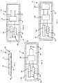
Fig. 1 is diagrammatic representation of the structure of a patient support apparatus that is connected to a network in a hospital and in communication with a passive wireless sensor through a wireless connection;Fig. 2 is a diagrammatic side view of a first embodiment of the passive wireless sensor ofFig. 1 ;Fig. 3 is a diagrammatic top plan view of a second embodiment of a passive wireless sensor;Fig. 4 is a diagrammatic top plan view of a third embodiment of a passive wireless sensor;Fig. 5 is a diagrammatic top plan view of a fourth embodiment of a passive wireless sensor;Fig. 6 is the portion of a flowchart describing an operational process of a controller of the patient support apparatus ofFig. 1 ;Fig. 7 is the remaining portion of the flowchart ofFig. 6 ;Fig. 8 is a flowchart representation of a subroutine of the operational process ofFigs. 6 and7 describing how data received from an wireless sensor is identified by the controller;Fig. 9 is a flowchart representation of a subroutine of the operational process ofFigs. 6 and7 describing how data is analyzed to determine if a predetermined condition established in the controller is met by the wireless sensor;Fig. 10 is a flowchart representation of a subroutine of the operational process ofFigs.6 and7 describing how data from the wireless sensor is associated with the patient support apparatus; and- Fig. 11 is a perspective view of a patient support apparatus that includes a number of readers for reading data from passive wireless sensors.
- A
system 10 for gathering information from awireless sensor 14 and transferring the information to ahealth information database 30 includes apatient support apparatus 12 that hascommunication circuitry 18 that is operable to communicate withcommunication circuitry 20 of thewireless sensor 14 as suggested byFig. 1 . Theillustrative wireless sensor 14 includessensor circuitry 15 that is operable to determine a vital sign of a patient. - As shown in
Fig. 2 , thesensor 14 comprises a thin patch ofpolyester 40, with an adhesive 42 that secures thesensor 14 to the skin of a patient. Thesensor 14 further includes a thin-film circuit 44 that is mounted to thepolyester patch 40, the thin-film circuit 44 including thecommunication circuitry 20 and thesensor circuitry 15. The details of various embodiments of thin-film circuits will be discussed in further detail below. In some embodiments, thewireless sensor 14 may be a passive device that is unpowered and is operable to be energized inductively. In other embodiments, thewireless sensor 14 may have a small charge source, such as a battery, for example, to power the thin-film circuit 44. Various embodiments of thewireless sensor 14 may be configured for detecting one more biophysical characteristics of a patient such as heart rate, temperature, respiration rate, blood pressure, pulse oximetry, electrocardiographic (EKG) information, electroencephalographic (EEG), information, muscle movement, or other similar information. Other embodiments of thewireless sensor 14 may be configured to detecting one or more biochemical characteristics of a patient such as pathogens and/or chemical markers, chemical or biological markers, biomarkers, or the like. In one embodiment, thewireless sensor 14 is a monitoring sensor available from MC10, Inc. of Cambridge, Massachusetts. When detecting biochemical characteristics, thesensor circuitry 15 may include metal oxide type semi-conductor sensors and surface acoustic wave devices. In another embodiment, protein based biosensors such as odarant binding proteins, sensory appendage proteins, odorant or gustatory receptors, serpentine receptors and / or odarant degrading enzymes may be used along with electrochemical transducers to generate an electrical signal in response to detection of a chemical. In some embodiments, thesensor circuitry 15 may monitor for the presence of biochemical markers of wound development such as IL-1α and Creatine Phosphokinase (CPK). - Utilizing the close proximity of the
wireless sensor 14 to thepatient support apparatus 12, the identity of the patient to which thewireless sensor 14 is applied allows the association of the person with thepatient support apparatus 12. Based on this association, the data from thewireless sensor 14 is transmitted by thepatient support apparatus 12 to anetwork 32 that couples thepatient support apparatus 12 to ahospital information system 34, utilizing the information about the person to associate the data with the person's specific electronic medical record. In other embodiments, thenetwork 32 may be coupled to a traditional nurse call system. - The
wireless sensor 14 includes thewireless communication circuitry 20. Thepatient support apparatus 12 includes acontroller 16 which includes thecommunication circuitry 18 that acts as an interface to thewireless sensor 14. Thecontroller 16 also includes an I/O subsystem 22 coupled to thecommunication circuitry 18 as well as aprocessor 26 and amemory device 28. Theprocessor 26 is operable to use instructions stored inmemory 28 to operate the I/O subsystem 22 which controlscommunication circuitry 18 as well as communication with thenetwork 32. Thecontroller 16 is in communication with peripheral devices of the patient support apparatus, such asperipheral device 24 shown inFig. 1 .Peripheral device 24 may be any of a number of subsystems of a patient support apparatus known in the art. For example ifpatient support apparatus 12 is embodied as a hospital bed,peripheral device 24 may include any one of a scale system, side rail position monitoring system, a brake mechanism monitoring system, a bed position monitoring system, a patient position monitoring system including bed exit detection capability, or a therapy device such as a therapeutic mattress, for example. In general,peripheral device 24 may be embodied as any subsystem or device that monitors a patient condition, monitors and operating condition of the patient support apparatus, controls and operating condition of the patient support apparatus, or provides therapy to patient supported on thepatient support apparatus 12. - It is contemplated that the
controller 16 may be programmed to operate as a universal interface capable of communicating with any of a number ofdifferent wireless sensors 14. During normal operation,controller 16 will regularly attempt to initiate communication with a wireless sensor such that any wireless sensor within the operating range of thecommunication circuitry 18 of thecontroller 16 may be detected and engaged by thecontroller 16. - The
patient support apparatus 12 may also include one or moreseparate readers 46 that are coupled to thecontroller 16, the readers includingcommunication circuitry 48 that communicates with the I/O subsystem 22 to share information with thecontroller 16. As shown in Fig. 11,separate readers patient support apparatus 12. Anotherreader 466 is positioned in a headboard 54. Still anotherreader 467 is positioned in a footboard 56.Additional readers readers 461,- 4611 are optional and may be included depending on the needs of a particular application. - The
communication circuitry 18 includes an antenna 88 that receives the wireless signal from thesensor 14 and aninductor 90 that is operable to generate a magnetic field that generates a current in aninductor 64 of thecommunication circuitry 20 of thewireless sensor 14. Thecommunication circuitry 20 also includes apower circuit 66 that is operable to convert the current generated in theinductor 64 to power thecommunication circuitry 20 andsensor circuitry 15 of thewireless sensor 14. Thecommunication circuitry 20 also includes anantenna 68 that transmits signals from thecommunication circuitry 20 to thecommunication circuitry 18 of the controller. - Each
reader 461,- 4611 includes a separate structure similar to thecommunication circuitry 18 of thecontroller 16, but are spaced apart from thecontroller 16 and communicate through the I/O subsystem 22. Referring again toFig. 1 , thereader 46 includes anantenna 70 and aninductor 72 that are operable to communicate with awireless sensor 14. Because thewireless sensor 14 is a passive device, thecontroller 16 is operable to cause theinductor 72 of a particular reader461,- 4611 to generate a magnetic field on an intermittent basis. When the magnetic field is generated, awireless sensor 14 in range of thereader 46 will receive power and begin to operate thesensor circuitry 15 andcommunication circuitry 20. - In one embodiment shown in
Fig. 3 , a wireless sensor 14' includes sensory circuitry 15' that includeslogic 74 and a pair ofleads polyester patch 40 is formed with openings that allow theleads logic 74 are configured to measure electrical activity such as a heart rate. - In another embodiment, a
wireless sensor 14" includes athermocouple 80 in communication withlogic 82 as shown inFig. 4 . Thethermocouple 80 is used to determine the temperature of a patient's skin. In still another embodiment shown inFig. 5 , wireless sensor 14'" includes anelectrochemical cell 84 that includes a chemistry that is responsive to an analyte that is introduced to theelectrochemical cell 84. The output of theelectrochemical cell 84 is used bylogic 86, thelogic 86 communicating the results of the analysis to the communication circuitry 20'" to be transmitted to thecontroller 16. The analyte is responsive to the chemistry such that an enzymatic reaction occurs generating a current in theelectrochemical cell 84 that is proportional to the quantity of analyte, such as CPK, for example. It should be understood that any of a number of other biophysical or biochemical sensing structures may be implemented in the wireless sensors disclosed herein. - A
process 200 shown inFigs. 6-7 provides an overview of the various actions thecontroller 16 may take in relation to thewireless sensor 14. Process steps shown in phantom indicate that the particular process step is optional as will be discussed in further detail below. At theinitial process step 202 thecontroller 16 establishes a communication connection with thewireless sensor 14 with thecommunication circuitry 18 ofcontroller 16 operating to initiate communications with thewireless communication circuitry 20 of thewireless sensor 14. Process 200 proceeds to processstep 204 where thecontroller 16 requests data from thewireless sensor 14. Atprocess step 204controller 16 will at least request sufficient data from thewireless sensor 14 to establish the identity of the person to which thewireless sensor 14 is applied. Other data may be also requested from thewireless sensor 14, such as operating a device serial number and sensor data from thesensor circuitry 15. In embodiments where thewireless sensor 14 includes a charge source, such as a battery, for example, it is contemplated that the request for data from thewireless sensor 14 will be intermittent to limit the power consumption of thewireless sensor 14.Process 200 proceeds todecision step 206 where thecontroller 16 evaluates whether data has been received from thewireless sensor 14. Received data may be in response to a request made atprocess step 204. If no data has been received,process 200 returns and continues to monitor for received data. If data is received from thewireless sensor 14,process 200 proceeds to asubroutine 400 that is used to identify the received data.Subroutine 400 will be discussed in further detail below.Process 200 then proceeds todecision step 208 to determine whether data that has been received from thewireless sensor 14 should trigger an alert. Alerts may be triggered by a malfunction of thewireless sensor 14 or a negative physiological condition of the patient as detected by thewireless sensor 14.- If no immediate alert is necessary, then process 200 proceeds to
subroutine 500 in which the data that is provided is analyzed by thecontroller 16 as will be discussed in further detail below. It should be understood that an output ofsubroutine 500 may include analysis of data that when analyzed indicates an intervention is required. Process 200 proceeds tooptional process step 210 in which thecontroller 16 may change an operating parameter of thepatient support apparatus 12. This may include the modification of the operation of anyperipheral device 24. For example, if data received from thewireless sensor 14 indicates that a patient is in cardiac arrest or respiratory distress,controller 16 may automatically move one or more patient support apparatus member to a position which assists a caregiver in intervening with the patient. In the case of cardiac arrest,controller 16 may move the bed to a CPR position in anticipation of a caregiver having to perform CPR on the patient. If data from thewireless sensor 14 indicates that the patient is in respiratory distress, for example,controller 16 may move a member of thepatient support apparatus 12 to position which increases the angle of incline of the patient's upper body so that the patient is better able to breathe. In still another example, if thewireless sensor 14 is operable to detect a patient's blood pressure, and blood pressure is determined to be low,controller 16 may move the patient support apparatus members such that the patient's legs are elevated. If theperipheral device 24 is a therapeutic mattress,controller 16 may change the operation of the therapeutic mattress, for example, to increase a relative level of pulmonary therapy.Process 200 then proceeds to subroutine 600 were thecontroller 16 is operable to notify thehospital information system 34 of information related to thewireless sensor 14. As will be discussed in further detail below thesubroutine 600 is operable to associate information regarding thewireless sensor 14 with the person to which thewireless sensor 14 is applied and thepatient support apparatus 12 so that the information may be properly placed in thehealth information database 30 and associated with the particular persons electronic medical record.- Referring now to
Fig. 8 ,subroutine 400 includes afirst process step 402 in which thecontroller 16 is operable to identify thewireless sensor 14 as a particular wireless sensor. Asub-process step 404 is a handshaking protocol that is used to confirm the compatibility of thecontroller 16 as an interface of thewireless sensor 14. In identifying theparticular wireless sensor 14, thecontroller 16 may optionally receive a unique identifier from thewireless sensor 14 as indicated byoptional process step 406. Once the relationship between theparticular wireless sensor 14 and thecontroller 16 is established, thecontroller 16 receives identifying data from theparticular wireless sensor 14. This data may include an explicit patient identification number or other information that associates thewireless sensor 14 with a particular patient. As noted above, oncesubroutine 400 is completedprocess 200 continues to thedecision step 208 discussed above. - As discussed above
subroutine 500, shown inFig. 9 , includes afirst decision step 502 where it is determined if a condition is pre-established on thecontroller 16 that is related to data from theparticular wireless sensor 14. If no such condition is pre-established on thecontroller 16, then thesubroutine 500 loops back and continues to monitor for data from a wireless sensor that does have a condition that is pre-established on thecontroller 16. If it is determined that a health condition or device malfunction condition that is pre-established oncontroller 16 does relate to data from theparticular wireless sensor 14,subroutine 500 proceeds todecision step 504 where the condition is further evaluated to determine if it is a function of a single wireless sensor, or of multiple wireless sensors. If it is determined atdecision step 504 that the condition is dependent on only theparticular wireless sensor 14,subroutine 500 progresses todecision step 508 to determine whether the condition has been met. If the condition has not been met, then subroutine 500 loops back and continues to monitor for relevant data. If the condition has been met as evaluated atdecision step 508, then process 200 proceeds to eitheroptional process step 210 orsubroutine 600 as described above. - If at
decision step 504 for it is determined that the condition is a function of multiple wireless sensors, then subroutine 500 proceeds to processstep 506 where data from other wireless sensors orperipheral devices 24 is retrieved so that all of the data from each of the relevant devices may be evaluated to determine whether a condition has been met atdecision step 508. Such a situation may exist when, for example, data from awireless sensor 14 that acts as a blood pressure sensor is compared to data from awireless sensor 14 that acts as an EKG sensor and the combined conditions of the two indicate an unsafe condition or a level of distress in the patient that may not be identified by either device independently. In some embodiments, the information from thewireless sensor 14 may be compared to information from one of theperipheral devices 24 to determine if a particular condition has been met. For example, aperipheral device 24 may be a traditional blood pressure monitor and awireless sensor 14 may be an EKG sensor and the condition may involve evaluating data from both the blood pressure monitor and a cardiac defibrillator to determine whether the condition has been met. - When
subroutine 600 is invoked, the data from thewireless sensor 14 is associated with a unique identifier for the particularpatient support apparatus 12. A unique identifier for thepatient support apparatus 12 is maintained inmemory 28 and is associated with data from thewireless sensor 14 using methods known in the art.Subroutine 600 then proceeds to processstep 604 where the associated data is transmitted to thehospital information system 34 over thenetwork 32 to be stored in thehealth information database 30.Process step 604 includes anoptional process step 608 that includes transmitting alert information to thehospital information system 34 if an alert condition is generated by thewireless sensor 14. If the condition has been determined to be met insubroutine 500, that information may also be transferred over thenetwork 32 to thehospital information system 34. In other embodiments, the I/O subsystem 22 may also transmit the alert condition to a nurse's station over a traditional nurse call cable. - Information may be transferred over the
network 32 to thehospital information system 34 by thecontroller 16 in real time, or may be stored inmemory 28 and transferred to thenetwork 32 on an intermittent basis. In still other embodiments, when the information is stored on thecontroller 16, thehospital information system 34 may be operable to query thecontroller 16 to receive the most recent information stored bycontroller 16 inmemory 28.Controller 16 may combine and associate information fromperipheral devices 24 as well aswireless sensor 14 so that all of the information may be transferred to thehospital information system 34 as a single record. - It should be understood that the
network 32 may be connected to thepatient support apparatus 12 through a wired data link, or the network connection may be a wireless data link. - Although certain illustrative embodiments have been described in detail above, variations and modifications exist.
Claims (15)
- A method for transferring medical data from a wireless sensor to a health information system, the method comprising receiving medical data from the wireless sensor (14), determining an identity of the wireless sensor (14), determining a nature of the received medical data; and transmitting the received medical data to the health information system (34) subsequent to determining the nature of the received medical data,characterized in that the method is for transferring medical data from a wireless sensor to a health information system using a patient support apparatus (12)in that the method comprises wirelessly transferring, with the patient support apparatus (12), a supply of power to the wireless sensor (14) to initiate operation of the wireless sensor (14), the medical data from the wireless sensor (14) being received with the patient support apparatus (12) while wirelessly transferring the supply of power to the wireless sensor (14), the identity of the wireless sensor (14) being determined on the patient support apparatus (12), and the nature of the received medical data being determined with the patient support apparatus (12);in that the method further comprises associating the received medical data with the patient support apparatus (12), andin that the received medical data and data identifying the associated patient support apparatus (12) are transmitted from the patient support apparatus (12) to the health information system (34) in response to determining the nature of the received medical data.
- The method of claim 1, wherein receiving the medical data comprises receiving the medical data from wireless communication circuitry (18).
- The method of either claim 1 or claim 2, wherein receiving the medical data from the wireless sensor (14) is in response to establishing a wireless communication connection between the patient support apparatus (12) and the wireless sensor (14).
- The method of any preceding claim, wherein receiving the medical data is in response to transmitting, from the patient support apparatus (12), a request for the medical data.
- The method of any preceding claim, wherein determining the identity of the wireless sensor (14) comprises performing, on the patient support apparatus (12), a handshaking protocol with the wireless sensor (14).
- The method of claim 5, wherein performing the handshaking protocol comprises receiving, with the patient support apparatus (12), a unique identifier of the wireless sensor (14) from the wireless sensor (14).
- The method of any preceding claim, wherein determining the nature of the received medical data comprises receiving identifying information associated with the medical data from the wireless sensor (14).
- The method of any preceding claim, wherein transmitting the received medical data and the data identifying the associated patient support apparatus (12) comprises transmitting an alert message to the hospital information system.
- The method of claim 8, wherein transmitting the alert message comprises transmitting an alert message to a nurse's station using a nurse call cable.
- The method of claim 8, wherein transmitting the alert message comprises wirelessly transmitting the alert message.
- The method of any preceding claim, further comprising analyzing, on the patient support apparatus (12), the received medical data to determine whether a health condition is met, the health condition and associated medical data criteria having been pre-established on the patient support apparatus (12).
- The method of claim 11, further comprising performing a non-therapeutic function using the patient support apparatus (12) in response to the received medical data satisfying the health condition.
- The method of claim 12, wherein performing the non-therapeutic function comprises at least one of: automatically performing a mechanical function and transmitting an alarm to the hospital information system.
- The method of any preceding claim, further comprising transmitting, from the patient support apparatus (12) to the wireless sensor (14), instructions to update the wireless sensor (14) in response to receiving the instructions from the hospital information system.
- A controller (16) of a patient support apparatus comprising a processor (26),and a memory (28) having stored therein a plurality of instructions that when executed by the processor cause the controller to implement the method of claim 1.
Applications Claiming Priority (1)
| Application Number | Priority Date | Filing Date | Title |
|---|---|---|---|
| US201361791019P | 2013-03-15 | 2013-03-15 |
Publications (2)
| Publication Number | Publication Date |
|---|---|
| EP2779002A1 EP2779002A1 (en) | 2014-09-17 |
| EP2779002B1true EP2779002B1 (en) | 2018-07-04 |
Family
ID=50389213
Family Applications (1)
| Application Number | Title | Priority Date | Filing Date |
|---|---|---|---|
| EP14159539.7AActiveEP2779002B1 (en) | 2013-03-15 | 2014-03-13 | Hospital bed for receiving data from thin patch wireless sensors |
Country Status (2)
| Country | Link |
|---|---|
| US (1) | US20140266643A1 (en) |
| EP (1) | EP2779002B1 (en) |
Families Citing this family (8)
| Publication number | Priority date | Publication date | Assignee | Title |
|---|---|---|---|---|
| US9901503B2 (en) | 2008-03-13 | 2018-02-27 | Optimedica Corporation | Mobile patient bed |
| US20140191880A1 (en)* | 2013-01-10 | 2014-07-10 | Covidien Lp | System, method, and software for ambulatory patient monitoring |
| US20160338591A1 (en)* | 2015-05-21 | 2016-11-24 | Hill-Rom Services, Inc. | Systems and methods for mitigating tissue breakdown |
| US10910102B2 (en)* | 2015-05-22 | 2021-02-02 | Hill-Rom Services, Inc. | In-bed patient identity verification and data collection |
| US11559421B2 (en) | 2015-06-25 | 2023-01-24 | Hill-Rom Services, Inc. | Protective dressing with reusable phase-change material cooling insert |
| WO2017052404A1 (en)* | 2015-09-25 | 2017-03-30 | Людмила Андреевна КАРАОГЛАНОВА | Method and system for processing medical data |
| CN109276384A (en)* | 2017-07-21 | 2019-01-29 | 青岛大数华创科技有限公司 | It is a kind of intelligent baby bed |
| US11583437B2 (en) | 2018-02-06 | 2023-02-21 | Aspen Surgical Products, Inc. | Reusable warming blanket with phase change material |
Family Cites Families (11)
| Publication number | Priority date | Publication date | Assignee | Title |
|---|---|---|---|---|
| US20050102167A1 (en)* | 2003-11-12 | 2005-05-12 | Kapoor Ashok K. | Provisioning and controlling medical instruments using wireless data communication |
| DE102004025797B3 (en)* | 2004-05-26 | 2005-12-15 | Dräger Medical AG & Co. KGaA | Patient care unit with a lying surface |
| US7319386B2 (en)* | 2004-08-02 | 2008-01-15 | Hill-Rom Services, Inc. | Configurable system for alerting caregivers |
| US8121856B2 (en)* | 2005-06-28 | 2012-02-21 | Hill-Rom Services, Inc. | Remote access to healthcare device diagnostic information |
| WO2008076464A2 (en)* | 2006-06-21 | 2008-06-26 | Surgisense Corporation | Wireless medical telemetry system and methods using radio-frequency energized biosensors |
| US8864205B2 (en)* | 2006-06-28 | 2014-10-21 | Stryker Corporation | Patient support with wireless data and/or energy transfer |
| US20080147442A1 (en)* | 2006-12-18 | 2008-06-19 | General Electric Company | Smart bed system and apparatus |
| US7868740B2 (en)* | 2007-08-29 | 2011-01-11 | Hill-Rom Services, Inc. | Association of support surfaces and beds |
| US8606344B2 (en)* | 2008-04-30 | 2013-12-10 | Board Of Regents, The University Of Texas System | Integrated patient bed system |
| US8405502B2 (en)* | 2009-06-10 | 2013-03-26 | Qualcomm Incorporated | Identification and connectivity gateway wristband for hospital and medical applications |
| US20140081662A1 (en)* | 2011-02-11 | 2014-03-20 | Abbott Diabetes Care Inc. | Sensor-Based Informatics Telemedicine Disease Management Solution |
- 2014
- 2014-03-10USUS14/202,635patent/US20140266643A1/ennot_activeAbandoned
- 2014-03-13EPEP14159539.7Apatent/EP2779002B1/enactiveActive
Non-Patent Citations (1)
| Title |
|---|
| None* |
Also Published As
| Publication number | Publication date |
|---|---|
| EP2779002A1 (en) | 2014-09-17 |
| US20140266643A1 (en) | 2014-09-18 |
Similar Documents
| Publication | Publication Date | Title |
|---|---|---|
| EP2779002B1 (en) | Hospital bed for receiving data from thin patch wireless sensors | |
| JP7321214B2 (en) | Wireless patient monitoring system and method | |
| CN1964666B (en) | Physiological event handling system and method, inspecting apparatus and program thereof | |
| JP7197473B2 (en) | System and method for patient fall detection | |
| KR102309022B1 (en) | Artificial intelligence-based bio-signal remote monitoring system | |
| US9114054B2 (en) | System for monitoring the use of medical devices | |
| US20140018637A1 (en) | Cloud-Based Monitoring of Medical Devices | |
| US20190254537A1 (en) | Apparatus and system for monitoring | |
| US20150359489A1 (en) | Smart mobile health monitoring system and related methods | |
| CN101442931A (en) | Communication system, communication device, sensor device and method for monitoring the health status of a patient | |
| US20120179004A1 (en) | Medical monitoring network | |
| US20130204106A1 (en) | Cloud-Based Monitoring of Medical Devices | |
| US10905376B2 (en) | Physical parameter measuring | |
| US10667687B2 (en) | Monitoring system for physiological parameter sensing device | |
| US20240075271A1 (en) | Wireless Communication and Power Conservation for Implantable Monitors | |
| EP3344132A1 (en) | Wireless medical evaluation device | |
| KR20210128576A (en) | Healthcare system based on wearable devices | |
| US20180146913A1 (en) | Pressure ulcer prevention with wearable monitoring | |
| KR102016215B1 (en) | care patient monitoring system | |
| JP2023518528A (en) | Devices, systems and methods for monitoring patient physiology | |
| AU2018206855A1 (en) | Apparatus and system for monitoring | |
| CN116847778A (en) | Wearable device for measuring multiple biological signals and artificial intelligence-based remote monitoring system using the same | |
| HK1233468A1 (en) | Physiological event handling system, method, and device; monitoring device and program product |
Legal Events
| Date | Code | Title | Description |
|---|---|---|---|
| 17P | Request for examination filed | Effective date:20140313 | |
| AK | Designated contracting states | Kind code of ref document:A1 Designated state(s):AL AT BE BG CH CY CZ DE DK EE ES FI FR GB GR HR HU IE IS IT LI LT LU LV MC MK MT NL NO PL PT RO RS SE SI SK SM TR | |
| AX | Request for extension of the european patent | Extension state:BA ME | |
| PUAI | Public reference made under article 153(3) epc to a published international application that has entered the european phase | Free format text:ORIGINAL CODE: 0009012 | |
| R17P | Request for examination filed (corrected) | Effective date:20150317 | |
| RBV | Designated contracting states (corrected) | Designated state(s):AL AT BE BG CH CY CZ DE DK EE ES FI FR GB GR HR HU IE IS IT LI LT LU LV MC MK MT NL NO PL PT RO RS SE SI SK SM TR | |
| GRAP | Despatch of communication of intention to grant a patent | Free format text:ORIGINAL CODE: EPIDOSNIGR1 | |
| STAA | Information on the status of an ep patent application or granted ep patent | Free format text:STATUS: GRANT OF PATENT IS INTENDED | |
| INTG | Intention to grant announced | Effective date:20180122 | |
| GRAS | Grant fee paid | Free format text:ORIGINAL CODE: EPIDOSNIGR3 | |
| GRAA | (expected) grant | Free format text:ORIGINAL CODE: 0009210 | |
| STAA | Information on the status of an ep patent application or granted ep patent | Free format text:STATUS: THE PATENT HAS BEEN GRANTED | |
| AK | Designated contracting states | Kind code of ref document:B1 Designated state(s):AL AT BE BG CH CY CZ DE DK EE ES FI FR GB GR HR HU IE IS IT LI LT LU LV MC MK MT NL NO PL PT RO RS SE SI SK SM TR | |
| REG | Reference to a national code | Ref country code:GB Ref legal event code:FG4D | |
| REG | Reference to a national code | Ref country code:CH Ref legal event code:EP | |
| REG | Reference to a national code | Ref country code:AT Ref legal event code:REF Ref document number:1015272 Country of ref document:AT Kind code of ref document:T Effective date:20180715 | |
| REG | Reference to a national code | Ref country code:IE Ref legal event code:FG4D | |
| REG | Reference to a national code | Ref country code:DE Ref legal event code:R096 Ref document number:602014027755 Country of ref document:DE | |
| REG | Reference to a national code | Ref country code:NL Ref legal event code:MP Effective date:20180704 | |
| REG | Reference to a national code | Ref country code:LT Ref legal event code:MG4D | |
| REG | Reference to a national code | Ref country code:DE Ref legal event code:R079 Ref document number:602014027755 Country of ref document:DE Free format text:PREVIOUS MAIN CLASS: G06F0019000000 Ipc:G16Z0099000000 | |
| REG | Reference to a national code | Ref country code:AT Ref legal event code:MK05 Ref document number:1015272 Country of ref document:AT Kind code of ref document:T Effective date:20180704 | |
| PG25 | Lapsed in a contracting state [announced via postgrant information from national office to epo] | Ref country code:NL Free format text:LAPSE BECAUSE OF FAILURE TO SUBMIT A TRANSLATION OF THE DESCRIPTION OR TO PAY THE FEE WITHIN THE PRESCRIBED TIME-LIMIT Effective date:20180704 | |
| PG25 | Lapsed in a contracting state [announced via postgrant information from national office to epo] | Ref country code:GR Free format text:LAPSE BECAUSE OF FAILURE TO SUBMIT A TRANSLATION OF THE DESCRIPTION OR TO PAY THE FEE WITHIN THE PRESCRIBED TIME-LIMIT Effective date:20181005 Ref country code:NO Free format text:LAPSE BECAUSE OF FAILURE TO SUBMIT A TRANSLATION OF THE DESCRIPTION OR TO PAY THE FEE WITHIN THE PRESCRIBED TIME-LIMIT Effective date:20181004 Ref country code:BG Free format text:LAPSE BECAUSE OF FAILURE TO SUBMIT A TRANSLATION OF THE DESCRIPTION OR TO PAY THE FEE WITHIN THE PRESCRIBED TIME-LIMIT Effective date:20181004 Ref country code:PL Free format text:LAPSE BECAUSE OF FAILURE TO SUBMIT A TRANSLATION OF THE DESCRIPTION OR TO PAY THE FEE WITHIN THE PRESCRIBED TIME-LIMIT Effective date:20180704 Ref country code:SE Free format text:LAPSE BECAUSE OF FAILURE TO SUBMIT A TRANSLATION OF THE DESCRIPTION OR TO PAY THE FEE WITHIN THE PRESCRIBED TIME-LIMIT Effective date:20180704 Ref country code:LT Free format text:LAPSE BECAUSE OF FAILURE TO SUBMIT A TRANSLATION OF THE DESCRIPTION OR TO PAY THE FEE WITHIN THE PRESCRIBED TIME-LIMIT Effective date:20180704 Ref country code:FI Free format text:LAPSE BECAUSE OF FAILURE TO SUBMIT A TRANSLATION OF THE DESCRIPTION OR TO PAY THE FEE WITHIN THE PRESCRIBED TIME-LIMIT Effective date:20180704 Ref country code:CZ Free format text:LAPSE BECAUSE OF FAILURE TO SUBMIT A TRANSLATION OF THE DESCRIPTION OR TO PAY THE FEE WITHIN THE PRESCRIBED TIME-LIMIT Effective date:20180704 Ref country code:RS Free format text:LAPSE BECAUSE OF FAILURE TO SUBMIT A TRANSLATION OF THE DESCRIPTION OR TO PAY THE FEE WITHIN THE PRESCRIBED TIME-LIMIT Effective date:20180704 Ref country code:IS Free format text:LAPSE BECAUSE OF FAILURE TO SUBMIT A TRANSLATION OF THE DESCRIPTION OR TO PAY THE FEE WITHIN THE PRESCRIBED TIME-LIMIT Effective date:20181104 Ref country code:AT Free format text:LAPSE BECAUSE OF FAILURE TO SUBMIT A TRANSLATION OF THE DESCRIPTION OR TO PAY THE FEE WITHIN THE PRESCRIBED TIME-LIMIT Effective date:20180704 | |
| PG25 | Lapsed in a contracting state [announced via postgrant information from national office to epo] | Ref country code:AL Free format text:LAPSE BECAUSE OF FAILURE TO SUBMIT A TRANSLATION OF THE DESCRIPTION OR TO PAY THE FEE WITHIN THE PRESCRIBED TIME-LIMIT Effective date:20180704 Ref country code:LV Free format text:LAPSE BECAUSE OF FAILURE TO SUBMIT A TRANSLATION OF THE DESCRIPTION OR TO PAY THE FEE WITHIN THE PRESCRIBED TIME-LIMIT Effective date:20180704 Ref country code:HR Free format text:LAPSE BECAUSE OF FAILURE TO SUBMIT A TRANSLATION OF THE DESCRIPTION OR TO PAY THE FEE WITHIN THE PRESCRIBED TIME-LIMIT Effective date:20180704 Ref country code:ES Free format text:LAPSE BECAUSE OF FAILURE TO SUBMIT A TRANSLATION OF THE DESCRIPTION OR TO PAY THE FEE WITHIN THE PRESCRIBED TIME-LIMIT Effective date:20180704 | |
| REG | Reference to a national code | Ref country code:DE Ref legal event code:R097 Ref document number:602014027755 Country of ref document:DE | |
| PG25 | Lapsed in a contracting state [announced via postgrant information from national office to epo] | Ref country code:EE Free format text:LAPSE BECAUSE OF FAILURE TO SUBMIT A TRANSLATION OF THE DESCRIPTION OR TO PAY THE FEE WITHIN THE PRESCRIBED TIME-LIMIT Effective date:20180704 Ref country code:RO Free format text:LAPSE BECAUSE OF FAILURE TO SUBMIT A TRANSLATION OF THE DESCRIPTION OR TO PAY THE FEE WITHIN THE PRESCRIBED TIME-LIMIT Effective date:20180704 Ref country code:IT Free format text:LAPSE BECAUSE OF FAILURE TO SUBMIT A TRANSLATION OF THE DESCRIPTION OR TO PAY THE FEE WITHIN THE PRESCRIBED TIME-LIMIT Effective date:20180704 | |
| PLBE | No opposition filed within time limit | Free format text:ORIGINAL CODE: 0009261 | |
| STAA | Information on the status of an ep patent application or granted ep patent | Free format text:STATUS: NO OPPOSITION FILED WITHIN TIME LIMIT | |
| PG25 | Lapsed in a contracting state [announced via postgrant information from national office to epo] | Ref country code:SK Free format text:LAPSE BECAUSE OF FAILURE TO SUBMIT A TRANSLATION OF THE DESCRIPTION OR TO PAY THE FEE WITHIN THE PRESCRIBED TIME-LIMIT Effective date:20180704 Ref country code:DK Free format text:LAPSE BECAUSE OF FAILURE TO SUBMIT A TRANSLATION OF THE DESCRIPTION OR TO PAY THE FEE WITHIN THE PRESCRIBED TIME-LIMIT Effective date:20180704 Ref country code:SM Free format text:LAPSE BECAUSE OF FAILURE TO SUBMIT A TRANSLATION OF THE DESCRIPTION OR TO PAY THE FEE WITHIN THE PRESCRIBED TIME-LIMIT Effective date:20180704 | |
| 26N | No opposition filed | Effective date:20190405 | |
| PG25 | Lapsed in a contracting state [announced via postgrant information from national office to epo] | Ref country code:SI Free format text:LAPSE BECAUSE OF FAILURE TO SUBMIT A TRANSLATION OF THE DESCRIPTION OR TO PAY THE FEE WITHIN THE PRESCRIBED TIME-LIMIT Effective date:20180704 | |
| PG25 | Lapsed in a contracting state [announced via postgrant information from national office to epo] | Ref country code:MC Free format text:LAPSE BECAUSE OF FAILURE TO SUBMIT A TRANSLATION OF THE DESCRIPTION OR TO PAY THE FEE WITHIN THE PRESCRIBED TIME-LIMIT Effective date:20180704 | |
| REG | Reference to a national code | Ref country code:CH Ref legal event code:PL | |
| PG25 | Lapsed in a contracting state [announced via postgrant information from national office to epo] | Ref country code:LU Free format text:LAPSE BECAUSE OF NON-PAYMENT OF DUE FEES Effective date:20190313 | |
| REG | Reference to a national code | Ref country code:BE Ref legal event code:MM Effective date:20190331 | |
| PG25 | Lapsed in a contracting state [announced via postgrant information from national office to epo] | Ref country code:LI Free format text:LAPSE BECAUSE OF NON-PAYMENT OF DUE FEES Effective date:20190331 Ref country code:CH Free format text:LAPSE BECAUSE OF NON-PAYMENT OF DUE FEES Effective date:20190331 Ref country code:IE Free format text:LAPSE BECAUSE OF NON-PAYMENT OF DUE FEES Effective date:20190313 | |
| PG25 | Lapsed in a contracting state [announced via postgrant information from national office to epo] | Ref country code:BE Free format text:LAPSE BECAUSE OF NON-PAYMENT OF DUE FEES Effective date:20190331 | |
| PG25 | Lapsed in a contracting state [announced via postgrant information from national office to epo] | Ref country code:TR Free format text:LAPSE BECAUSE OF FAILURE TO SUBMIT A TRANSLATION OF THE DESCRIPTION OR TO PAY THE FEE WITHIN THE PRESCRIBED TIME-LIMIT Effective date:20180704 | |
| PG25 | Lapsed in a contracting state [announced via postgrant information from national office to epo] | Ref country code:MT Free format text:LAPSE BECAUSE OF NON-PAYMENT OF DUE FEES Effective date:20190313 Ref country code:PT Free format text:LAPSE BECAUSE OF FAILURE TO SUBMIT A TRANSLATION OF THE DESCRIPTION OR TO PAY THE FEE WITHIN THE PRESCRIBED TIME-LIMIT Effective date:20181105 | |
| PG25 | Lapsed in a contracting state [announced via postgrant information from national office to epo] | Ref country code:CY Free format text:LAPSE BECAUSE OF FAILURE TO SUBMIT A TRANSLATION OF THE DESCRIPTION OR TO PAY THE FEE WITHIN THE PRESCRIBED TIME-LIMIT Effective date:20180704 | |
| PG25 | Lapsed in a contracting state [announced via postgrant information from national office to epo] | Ref country code:HU Free format text:LAPSE BECAUSE OF FAILURE TO SUBMIT A TRANSLATION OF THE DESCRIPTION OR TO PAY THE FEE WITHIN THE PRESCRIBED TIME-LIMIT; INVALID AB INITIO Effective date:20140313 | |
| PG25 | Lapsed in a contracting state [announced via postgrant information from national office to epo] | Ref country code:MK Free format text:LAPSE BECAUSE OF FAILURE TO SUBMIT A TRANSLATION OF THE DESCRIPTION OR TO PAY THE FEE WITHIN THE PRESCRIBED TIME-LIMIT Effective date:20180704 | |
| PGFP | Annual fee paid to national office [announced via postgrant information from national office to epo] | Ref country code:DE Payment date:20250218 Year of fee payment:12 | |
| PGFP | Annual fee paid to national office [announced via postgrant information from national office to epo] | Ref country code:FR Payment date:20250218 Year of fee payment:12 | |
| PGFP | Annual fee paid to national office [announced via postgrant information from national office to epo] | Ref country code:GB Payment date:20250221 Year of fee payment:12 |