EP2777801B1 - Device for eliminating CO2 from patient blood - Google Patents
Device for eliminating CO2 from patient bloodDownload PDFInfo
- Publication number
- EP2777801B1 EP2777801B1EP13168103.3AEP13168103AEP2777801B1EP 2777801 B1EP2777801 B1EP 2777801B1EP 13168103 AEP13168103 AEP 13168103AEP 2777801 B1EP2777801 B1EP 2777801B1
- Authority
- EP
- European Patent Office
- Prior art keywords
- blood
- active
- gas
- fibers
- hollow fiber
- Prior art date
- Legal status (The legal status is an assumption and is not a legal conclusion. Google has not performed a legal analysis and makes no representation as to the accuracy of the status listed.)
- Active
Links
Images


Classifications
- A—HUMAN NECESSITIES
- A61—MEDICAL OR VETERINARY SCIENCE; HYGIENE
- A61M—DEVICES FOR INTRODUCING MEDIA INTO, OR ONTO, THE BODY; DEVICES FOR TRANSDUCING BODY MEDIA OR FOR TAKING MEDIA FROM THE BODY; DEVICES FOR PRODUCING OR ENDING SLEEP OR STUPOR
- A61M1/00—Suction or pumping devices for medical purposes; Devices for carrying-off, for treatment of, or for carrying-over, body-liquids; Drainage systems
- A61M1/36—Other treatment of blood in a by-pass of the natural circulatory system, e.g. temperature adaptation, irradiation ; Extra-corporeal blood circuits
- A61M1/3621—Extra-corporeal blood circuits
- A61M1/3627—Degassing devices; Buffer reservoirs; Drip chambers; Blood filters
- A—HUMAN NECESSITIES
- A61—MEDICAL OR VETERINARY SCIENCE; HYGIENE
- A61M—DEVICES FOR INTRODUCING MEDIA INTO, OR ONTO, THE BODY; DEVICES FOR TRANSDUCING BODY MEDIA OR FOR TAKING MEDIA FROM THE BODY; DEVICES FOR PRODUCING OR ENDING SLEEP OR STUPOR
- A61M1/00—Suction or pumping devices for medical purposes; Devices for carrying-off, for treatment of, or for carrying-over, body-liquids; Drainage systems
- A61M1/14—Dialysis systems; Artificial kidneys; Blood oxygenators ; Reciprocating systems for treatment of body fluids, e.g. single needle systems for hemofiltration or pheresis
- A61M1/16—Dialysis systems; Artificial kidneys; Blood oxygenators ; Reciprocating systems for treatment of body fluids, e.g. single needle systems for hemofiltration or pheresis with membranes
- A61M1/1698—Blood oxygenators with or without heat-exchangers
- A—HUMAN NECESSITIES
- A61—MEDICAL OR VETERINARY SCIENCE; HYGIENE
- A61M—DEVICES FOR INTRODUCING MEDIA INTO, OR ONTO, THE BODY; DEVICES FOR TRANSDUCING BODY MEDIA OR FOR TAKING MEDIA FROM THE BODY; DEVICES FOR PRODUCING OR ENDING SLEEP OR STUPOR
- A61M1/00—Suction or pumping devices for medical purposes; Devices for carrying-off, for treatment of, or for carrying-over, body-liquids; Drainage systems
- A61M1/36—Other treatment of blood in a by-pass of the natural circulatory system, e.g. temperature adaptation, irradiation ; Extra-corporeal blood circuits
- A61M1/3621—Extra-corporeal blood circuits
- A61M1/3666—Cardiac or cardiopulmonary bypass, e.g. heart-lung machines
- B—PERFORMING OPERATIONS; TRANSPORTING
- B01—PHYSICAL OR CHEMICAL PROCESSES OR APPARATUS IN GENERAL
- B01D—SEPARATION
- B01D19/00—Degasification of liquids
- B01D19/0031—Degasification of liquids by filtration
- B—PERFORMING OPERATIONS; TRANSPORTING
- B01—PHYSICAL OR CHEMICAL PROCESSES OR APPARATUS IN GENERAL
- B01D—SEPARATION
- B01D63/00—Apparatus in general for separation processes using semi-permeable membranes
- B01D63/02—Hollow fibre modules
- B01D63/026—Wafer type modules or flat-surface type modules
- A—HUMAN NECESSITIES
- A61—MEDICAL OR VETERINARY SCIENCE; HYGIENE
- A61M—DEVICES FOR INTRODUCING MEDIA INTO, OR ONTO, THE BODY; DEVICES FOR TRANSDUCING BODY MEDIA OR FOR TAKING MEDIA FROM THE BODY; DEVICES FOR PRODUCING OR ENDING SLEEP OR STUPOR
- A61M1/00—Suction or pumping devices for medical purposes; Devices for carrying-off, for treatment of, or for carrying-over, body-liquids; Drainage systems
- A61M1/36—Other treatment of blood in a by-pass of the natural circulatory system, e.g. temperature adaptation, irradiation ; Extra-corporeal blood circuits
- A61M1/3607—Regulation parameters
- A61M1/3609—Physical characteristics of the blood, e.g. haematocrit, urea
- A—HUMAN NECESSITIES
- A61—MEDICAL OR VETERINARY SCIENCE; HYGIENE
- A61M—DEVICES FOR INTRODUCING MEDIA INTO, OR ONTO, THE BODY; DEVICES FOR TRANSDUCING BODY MEDIA OR FOR TAKING MEDIA FROM THE BODY; DEVICES FOR PRODUCING OR ENDING SLEEP OR STUPOR
- A61M2205/00—General characteristics of the apparatus
- A61M2205/33—Controlling, regulating or measuring
- A61M2205/3331—Pressure; Flow
- A61M2205/3334—Measuring or controlling the flow rate
- A—HUMAN NECESSITIES
- A61—MEDICAL OR VETERINARY SCIENCE; HYGIENE
- A61M—DEVICES FOR INTRODUCING MEDIA INTO, OR ONTO, THE BODY; DEVICES FOR TRANSDUCING BODY MEDIA OR FOR TAKING MEDIA FROM THE BODY; DEVICES FOR PRODUCING OR ENDING SLEEP OR STUPOR
- A61M2205/00—General characteristics of the apparatus
- A61M2205/33—Controlling, regulating or measuring
- A61M2205/3368—Temperature
- A—HUMAN NECESSITIES
- A61—MEDICAL OR VETERINARY SCIENCE; HYGIENE
- A61M—DEVICES FOR INTRODUCING MEDIA INTO, OR ONTO, THE BODY; DEVICES FOR TRANSDUCING BODY MEDIA OR FOR TAKING MEDIA FROM THE BODY; DEVICES FOR PRODUCING OR ENDING SLEEP OR STUPOR
- A61M2230/00—Measuring parameters of the user
- A61M2230/20—Blood composition characteristics
- A61M2230/202—Blood composition characteristics partial carbon oxide pressure, e.g. partial dioxide pressure (P-CO2)
- A—HUMAN NECESSITIES
- A61—MEDICAL OR VETERINARY SCIENCE; HYGIENE
- A61M—DEVICES FOR INTRODUCING MEDIA INTO, OR ONTO, THE BODY; DEVICES FOR TRANSDUCING BODY MEDIA OR FOR TAKING MEDIA FROM THE BODY; DEVICES FOR PRODUCING OR ENDING SLEEP OR STUPOR
- A61M2230/00—Measuring parameters of the user
- A61M2230/20—Blood composition characteristics
- A61M2230/205—Blood composition characteristics partial oxygen pressure (P-O2)
- A—HUMAN NECESSITIES
- A61—MEDICAL OR VETERINARY SCIENCE; HYGIENE
- A61M—DEVICES FOR INTRODUCING MEDIA INTO, OR ONTO, THE BODY; DEVICES FOR TRANSDUCING BODY MEDIA OR FOR TAKING MEDIA FROM THE BODY; DEVICES FOR PRODUCING OR ENDING SLEEP OR STUPOR
- A61M2230/00—Measuring parameters of the user
- A61M2230/20—Blood composition characteristics
- A61M2230/208—Blood composition characteristics pH-value
- B—PERFORMING OPERATIONS; TRANSPORTING
- B01—PHYSICAL OR CHEMICAL PROCESSES OR APPARATUS IN GENERAL
- B01D—SEPARATION
- B01D2313/00—Details relating to membrane modules or apparatus
- B01D2313/60—Specific sensors or sensor arrangements
Definitions
- the inventionrelates to a device for the at least partial elimination of CO 2 from patient blood in the extracorporeal circuit with a CO 2 -Eliminator having a housing with a blood inlet and a blood outlet and a gas inlet and a gas outlet, wherein in the housing one of both the gas and Blood-permeable hollow fiber arrangement is provided with an active fiber length.
- COPDChoronic Obstructive Pulmonary Disease
- pCO 2hypocapnia, ventilation insufficiency
- helpcan be provided via respiration, however because of the applied overpressure and the forced filling with possible overstretching of the lung can lead to lung damage.
- Therapeutic proceduressuch as interventional lung assist (iLA) or extracorporeal membrane oxygenation (ECMO) may reduce respiratory effort and work of breathing in this situation, so that respiratory distress disappears and patient recovery is possible.
- iLAinterventional lung assist
- ECMOextracorporeal membrane oxygenation
- a device for supporting the lung function of a patientis known.
- This deviceis designed for a very low flow resistance of the blood side, so that can be dispensed with a driving pump with arterio-venous (AV) connection.
- AVarterio-venous
- this devicerequires a minimum blood flow of 0.5 liters per minute to be able to work effectively, and requires relatively large-lumen cannulas in passive AV operation.
- this deviceis effective only in a large invasiveness. Due to its design, this device is primarily suitable as an oxygenator or, in the case of relatively high blood flow, also for CO 2 elimination (mass transfer).
- the known systemhas the disadvantage that the blood flow is dependent on the AV pressure difference and the blood-side flow resistance. For a good efficiency, therefore, two separate accesses for the supply or discharge of the patient's blood with large-lumen cannulas / catheters and tubing systems and corresponding vascular accesses are required, which causes a high invasiveness. This means higher priming volume and greater impairment of the patient due to the additional larger wound surfaces and an application only in intensive care medicine where such vascular accesses can be placed. In addition, the extracorporeal circulation must be monitored intensively because of the high blood flow, as at Leakage or disconnection within a few seconds for the patient's mortal danger exists.
- a devicewhich consists of a housing integrated in an oxygenator with downstream dialyzer.
- the EP 1 524 000 A8discloses the use of such a device in a combined hemodialysis and CO 2 elimination system.
- the DE 10 2009 008 601 A1discloses a device for treating a biological fluid, comprising at least three chambers, wherein a first chamber, which is intended for receiving the biological fluid, and a second chamber, which is intended to receive a gas, separated by at least one gas-permeable and liquid-impermeable membrane are.
- the EP 1 864 709 A2discloses a device having in its interior a stack of membrane mats.
- the EP 1 810 704 A2discloses an oxygenator with upstream heat exchanger and downstream filter.
- the EP 0 521 495 A2discloses a device for mass transfer from a gas to a liquid or vice versa by means of rectilinear hollow fibers, in which the gas flows through the inner cavity of the hollow fibers and the end portions of the hollow fibers are embedded in a Vergussmassesko.
- the object of the present inventionis to provide a device for the at least partial elimination of CO 2 in hypercapnia, which offers high effectiveness with low invasiveness.
- the active fiber lengthis preferably a dimension of the cross section of the hollow fiber arrangement through which patient blood to be treated can flow.
- the path of the blood passageis the shortest path that the blood to be treated can take through the hollow fiber arrangement.
- the minimum distance of the blood passagecan correspond to a (further) dimension of the hollow fiber arrangement.
- the active fiber length and the minimum Distancecan thereby have an angle of 90 ° to each other.
- the hollow fibersare arranged in mats, wherein the fibers are aligned in parallel in the mats.
- the matsare stacked in the hollow fiber array so that the fibers are approximately perpendicular to each other in parallel adjacent mats.
- the path or blood flow directionis substantially perpendicular to the fiber orientation.
- the hollow fiberscan be either of the microporous or the diffusive type. Examples of the microporous or diffusive type are the microporous PP hollow fiber oxyphane or the diffusive PMP hollow fiber Oxyplus from Membrana.
- the hollow fiber arrangementis cuboidal.
- the device according to the inventionis preferably a device without a heat exchanger.
- the device according to the inventionit is possible to minimize the parameters blood flow, priming volume and pressure loss of both the blood and the gas side and the size of the intervention to the vascular access with high efficiency of CO 2 elimination.
- CO 2 eliminationis possible with the device according to the invention even at a low blood flow of 500 ml per minute. Due to the low blood flow, it is possible to work with small-lumen cannulas or even with a double-lumen cannula, with less invasiveness in vascular access, higher safety through preferential venous-venous (W) cannulation and associated lower blood pressure level and thereby lesser Monitoring effort are connected.
- Wpreferential venous-venous
- the purge gas supplied to the CO 2 eliminator via a gas inletcan basically be chosen arbitrarily.
- the requirementsare merely toxicological safety and extensive freedom from CO 2 .
- air or mixtures of air with oxygen, nitrogen or noble gasesare suitable to be used as purge gas.
- the quotient of active fiber length and total fiber lengthis ⁇ 0.79, preferably ⁇ 0.77, preferably 0.724 ⁇ 5%.
- the active fiber surface of the hollow fiber arrayis in the range 0.5 to 1.2 m 2 .
- the hollow fiber arrangementhas at least 13,000, preferably at least 13,300 exchange-active fibers.
- the hollow fiber arrangementmay have at least 13,300 hollow fibers per m 2 active exchange surface. With such a configuration of the hollow fiber arrangement, it is possible to achieve an approximate equilibrium state between the pCO 2 of the purge gas (near 0) and the pCO 2 of the treated blood.
- the purge gasDuring its passage through the short exchange-active part of the hollow fiber arrangement, the purge gas achieves only low values of pCO 2 by exchange, so that a higher gradient between pCO 2 in the purge gas and in the blood is maintained during the passage. A longer fiber would be ineffective due to a higher pCO 2 of the purge gas in the further course of the passage due to the lower gradient.
- At least one sensorcan be provided for detecting parameters of the blood to be treated.
- the sensorscan be integrated in the CO 2 -Elminator. Based on the recorded parameters, the effectiveness of CO 2 elimination can be checked. Possibly. the gas flow or blood flow can be controlled or regulated.
- an evaluation devicewhich is connected to the at least one sensor and is connected to a control device for controlling at least one parameter of the extracorporeal circuit.
- At least two cannulasare provided.
- at least two cannulassingle-lumen cannulas
- each with a lumen ⁇ 21 Frenchpreferably each with a lumen of 13 French
- at least one double-lumen cannula with two lumens ⁇ 24 Frenchpreferably with a lumen of 19 French.
- a balance between the pCO 2 of the incoming purge gas and the pCO 2 of the treated bloodis desired.
- a very high efficiency of CO 2 eliminationcan be achieved with low invasiveness.
- small-lumen, in particular double-lumen, veno-venous cannulas with low blood flowcan be used.
- the appropriate adjustment of the balancecan be achieved with low blood flow, a substantial liberation of the treated blood of CO 2 .
- a pCO 2 of the treated blood ⁇ 32 mm Hgpreferably ⁇ 25 mm Hg, more preferably ⁇ 15 mm Hg can be set, a value which is unphysiological even for arterial blood and with a pH> 7.45 pH> 7.6, particularly preferably pH 7.8, which is referred to as respiratory alkalosis.
- pCO 2 values in the range of 10-15 mm Hgwere determined at pH values around pH 7.8 in the treated blood.
- the deviceis operated with a blood flow ⁇ 1200 ml per minute, more preferably ⁇ 800 ml per minute, in particular ⁇ 500 ml per minute. This reduces the risk for the treated patient.
- smaller diameter cannulas and leadscan be used.
- a pH of the treated blood> 7.45can be set.
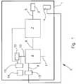
- the Fig. 1shows a device 1 in an extracorporeal circuit 2.
- the device 1has small-lumen cannulas 3, 4 for connection to a patient. These are shown here as single lumen cannulas but could be combined as a double lumen cannula.
- the device 1comprises a tube system 5.
- an optional pump 7is provided between the cannula 3 and a CO 2 -Eliminator 6 .
- the pumpmay be formed, for example, as a roller pump or centrifugal pump.
- an occlusive blood pumpe.g. As a roller pump, be beneficial because the blood flow is largely independent of pressure ratios proportional to the pump speed. Thus, a measurement of blood flow may be unnecessary.
- the CO 2 eliminator 6has a blood inlet 8 and a blood outlet 9. Furthermore, a gas inlet 10 and a gas outlet 11 are provided.
- the gas inlet 10is connected to a purge gas reservoir 12, z.
- a gas blender or a gas cylinderconnected as a gas line.
- At least one sensor 13is arranged to detect parameters of the treated blood.
- the sensor 13is connected to an evaluation device 14, which in turn is connected to a control device 15.
- various parameters of the CO 2 elimination processcan be regulated as a function of the detected and evaluated parameters.
- the pump 7can be regulated or the gas pressure of the purge gas.
- the control device 15may be connected, for example, with a control valve between the purge gas reservoir 12 and the gas inlet 10.
- the CO 2 -Eliminator 6is shown in a plan view.
- a connector 8.1is provided at the blood inlet and a connector 9.1 at the blood outlet.
- the sensor 13is located between the blood outlet 9 and the connector 9.1.
- the sensor 13is configured to detect temperature, blood flow, oxygen saturation, pCO 2 , pH, or other parameters of the treated blood.
- the CO 2 eliminator 6has a housing 20. At the top of the housing a cover 21 is provided, on which the gas inlet 10 is arranged.
- the Fig. 3shows a sectional view along the line AA of Fig. 2 ,
- a hollow fiber assembly 25is provided which has a plurality of mats with hollow fibers.
- non-cast fibersare provided in an exchange-active region 26, while in an edge region 27 the fibers are cast and thus are not active for the gas exchange.
- the active fiber lengthis indicated by the letter Y, ie a dimension of the cross section which is active for the gas exchange.
- the total fiber lengthis X and also includes the region 27 in which the fibers are potted and thus do not participate in the gas exchange.
- the total length of the fibersis thus with X and the exchange-active fiber length or active fiber length indicated by Y.
- Xthe exchange-active fiber length or active fiber length indicated by Y.
- Ythe exchange-active fiber length or active fiber length indicated by Y.
- the regions 28there is inflowing purge gas and in the regions 30, 31 is gas after flowing through the hollow fiber assembly 25. From this illustration also shows that due to the arrangement of blood inlet 8 and blood outlet 9, the blood flow perpendicular to the arrangement of the fibers of the hollow fiber assembly 25 takes place.
- the Fig. 4shows a sectional view along the line BB of Fig. 3 , Here again the active fiber length Y and the entire fiber length X are shown. Furthermore, the thickness Z of the hollow fiber arrangement can be seen here.
- the thickness Z of the hollow fiber arrangementcorresponds to the minimum distance of the blood passage, ie the shortest path that the blood can take through the hollow fiber arrangement.
- the blood flowtakes place substantially at right angles to the orientation of the hollow fibers in the hollow fiber arrangement 25.
- the Fig. 5shows a first (hollow fiber) mat 40 with a plurality of hollow fibers 40.1, 40.2, which are arranged parallel to each other. Furthermore, a second layer or mat 41 is shown with hollow fibers 41.1, 41.2, wherein the hollow fibers 41.1, 41.2 are arranged parallel to each other. However, the hollow fibers 40.1, 40.2 are arranged at right angles to the hollow fibers 41.1, 41.2. This means that the mats 40, 41 are layered crosswise.
- the purge gas supplied from the purge gas reservoir 12enters via the input-side gas chambers 28, 29 and cut surfaces of the encapsulation in the region 27 in the hollow fibers 40.1, 40., 41.1, 41.2, passes their Inside, wherein the exchange active portion Y of the entire fiber length X causes the gas exchange. Subsequently, the gas exits at the cut surfaces of the casting in the region 27 into the outlet-side gas chambers 30, 31 and escapes via the gas outlet 11 located on the underside of the CO 2 -liminator 6.
- an exchange active surfaceof about 0.5 m 2 to 1.2 m 2 is sufficient.
- the exchange active hollow fiberscan either be microporous or diffusive.
- This small quotient Y / Zwhich is not very different from 1, is the characteristic of a flow path which is optimized both on the gas side and on the gas side, and thus also for an optimized flow resistance for both media.
- the device describedhas the following design features: Surface for gas exchange: 1.3 m 2 Minimum active fiber length Y: 10.1 cm Total fiber length X: 12,7 cm Minimum distance of the blood passage Z 2.6 cm Maximum number of fibers 11712 Maximum number of fibers / m 2 9009
- the exchange-active fraction of the fibersis at least 79.5% and thus significantly higher than that of the device according to the invention.
- the gas exchange module at an active area of 0.98 m 2contains at least 13119 hollow fibers or at least 13300 hollow fibers per m 2 : Surface for gas exchange: 0,98 m 2 Maximum active fiber length (Y): 5.8 cm Total fiber length (X): 7.6 cm Minimum distance of the blood passage (Z) 5,4 cm Minimum number of fibers 13119 Minimum number of fibers / m 2 13300
- This small quotient Y / Zwhich is not very different from 1, is the characteristic of a flow path which is optimized both on the gas side and on the gas side, and thus also for an optimized flow resistance for both media.
- the gas exchange modulecontains at least 17 148 hollow fibers or at least 17 497 hollow fibers per m 2 with an active area of 0.98 m 2 and use of hollow fibers at the lower limit of the specification (outer diameter 0.35 mm): Surface for gas exchange: 0,98 m 2 Maximum active fiber length (Y): 5.2 cm Total fiber length (X): 7.6 cm Minimum distance of the blood passage (Z) 5,4 cm Minimum number of fibers 17148 Minimum number of fibers / m 2 17497
- This small quotient Y / Zwhich is not very different from 1, is the characteristic of a flow path which is optimized both on the gas side and on the gas side, and thus also for an optimized flow resistance for both media.
Landscapes
- Health & Medical Sciences (AREA)
- Heart & Thoracic Surgery (AREA)
- Vascular Medicine (AREA)
- Anesthesiology (AREA)
- Hematology (AREA)
- Veterinary Medicine (AREA)
- Public Health (AREA)
- Engineering & Computer Science (AREA)
- General Health & Medical Sciences (AREA)
- Biomedical Technology (AREA)
- Cardiology (AREA)
- Life Sciences & Earth Sciences (AREA)
- Animal Behavior & Ethology (AREA)
- Chemical & Material Sciences (AREA)
- Chemical Kinetics & Catalysis (AREA)
- Emergency Medicine (AREA)
- Urology & Nephrology (AREA)
- Pulmonology (AREA)
- External Artificial Organs (AREA)
Description
Translated fromGermanDie Erfindung betrifft eine Vorrichtung zur mindestens teilweisen Eliminierung von CO2 aus Patientenblut im extrakorporalen Kreislauf mit einem CO2-Eliminator, der ein Gehäuse mit einem Bluteinlass und einem Blutauslass sowie einem Gaseinlass und einem Gasauslass aufweist, wobei im Gehäuse eine sowohl vom Gas als auch Blut durchströmbare Hohlfaseranordnung mit einer aktiven Faserlänge vorgesehen ist.The invention relates to a device for the at least partial elimination of CO2 from patient blood in the extracorporeal circuit with a CO2 -Eliminator having a housing with a blood inlet and a blood outlet and a gas inlet and a gas outlet, wherein in the housing one of both the gas and Blood-permeable hollow fiber arrangement is provided with an active fiber length.
Die Erkrankung COPD (Chronic Obstructive Pulmonary Desease) führt zu einer Behinderung der Ausatmung und in Folge zu chronischer respiratorischer Insuffizienz. Die Symptome sind Atemnot und oft erhöhte pCO2-Werte. Bei dauerhaft erhöhten pCO2-Werten (Hyperkapnie, Ventilationsinsuffizienz) ist Hilfe über eine Beatmung möglich, die jedoch wegen des angewandten Überdrucks und der forcierten Füllung mit möglicher Überdehnung der Lunge zu Lungenschäden führen kann.The disease COPD (Chronic Obstructive Pulmonary Disease) leads to obstruction of the exhalation and consequently to chronic respiratory insufficiency. The symptoms are respiratory distress and often elevated pCO2 levels. With permanently increased pCO2 values (hypercapnia, ventilation insufficiency), help can be provided via respiration, however because of the applied overpressure and the forced filling with possible overstretching of the lung can lead to lung damage.
Therapieverfahren wie die pumpenlose extrakorporale Lungenunterstützung (Interventional Lung Assist (iLA)) oder extracorporal membrane oxygenation (ECMO)) können in dieser Situation den Atemantrieb und die Atemarbeit reduzieren, sodass die Atemnot verschwindet und eine Erholung des Patienten möglich wird.Therapeutic procedures such as interventional lung assist (iLA) or extracorporeal membrane oxygenation (ECMO) may reduce respiratory effort and work of breathing in this situation, so that respiratory distress disappears and patient recovery is possible.
Beispielsweise aus der
Das bekannte System hat den Nachteil, dass der Blutfluss abhängig von der AV-Druckdifferenz und dem blutseitigen Strömungswiderstand ist. Für eine gute Effizienz sind daher zwei getrennte Zugänge für die Zu- oder Abfuhr des Patientenblutes mit großlumigen Kanülen/Kathetern und Schlauchsystemen und entsprechenden Gefäßzugängen erforderlich, was eine hohe Invasivität bedingt. Dies bedeutet höheres Primingvolumen und stärkere Beeinträchtigung des Patienten durch die zusätzlichen größeren Wundflächen und eine Anwendung nur in der Intensivmedizin, wo solche Gefäßzugänge gelegt werden können. Zusätzlich muss der extrakorporale Kreislauf wegen des hohen Blutflusses intensiv überwacht werden, da bei einer Leckage oder Diskonnektierung innerhalb weniger Sekunden für den Patienten Lebensgefahr besteht.The known system has the disadvantage that the blood flow is dependent on the AV pressure difference and the blood-side flow resistance. For a good efficiency, therefore, two separate accesses for the supply or discharge of the patient's blood with large-lumen cannulas / catheters and tubing systems and corresponding vascular accesses are required, which causes a high invasiveness. This means higher priming volume and greater impairment of the patient due to the additional larger wound surfaces and an application only in intensive care medicine where such vascular accesses can be placed. In addition, the extracorporeal circulation must be monitored intensively because of the high blood flow, as at Leakage or disconnection within a few seconds for the patient's mortal danger exists.
Die gleichen Aussagen gelten auch für die ECMO-Anwendungen von Oxygenatoren. Auch hier werden zwei getrennte Zugänge für die Zu- oder Abfuhr des Patientenblutes mit großlumigen Kanülen/Kathetern und Schlauchsystemen und entsprechende Gefäßzugänge benötigt, was eine hohe Invasivität bedingt. Wegen der hohen Invasivität von ECMO-Anwendungen werden diese oft als letzte lebenserhaltende Maßnahme angesehen und angewendet, was zu hoher Mortalität und deshalb zu einer eher schlechten Akzeptanz dieser an sich guten Behandlungsmethode führt.The same statements apply to the ECMO applications of oxygenators. Again, two separate accesses for the supply or discharge of the patient's blood with large-lumen cannulas / catheters and tubing systems and corresponding vascular accesses are required, which causes a high invasiveness. Because of the high invasiveness of ECMO applications, these are often considered and used as a last life support measure, leading to high mortality and therefore poor acceptance of this good treatment method.
Aus der
Aus der
Die
Die
Aus der
Die
Die
Aufgabe der vorliegenden Erfindung ist es, eine Vorrichtung für die mindestens teilweise Eliminierung von CO2 bei Hyperkapnie bereitzustellen, die hohe Effektivität bei geringer Invasivität bietet.The object of the present invention is to provide a device for the at least partial elimination of CO2 in hypercapnia, which offers high effectiveness with low invasiveness.
Gelöst wird diese Aufgabe erfindungsgemäß durch eine Vorrichtung zur zumindest teilweisen CO2-Eliminierung von Patientenblut im extrakorporalen Kreislauf mit den Merkmalen des Anspruchs 1.This object is achieved according to the invention by a device for at least partial CO2 elimination of patient blood in the extracorporeal circulation with the features of
Dabei ist die aktive Faserlänge vorzugsweise eine Dimension des Querschnitts der Hohlfaseranordnung, der durch zu behandelndes Patientenblut durchströmbar ist. Die Wegstrecke der Blutpassage ist dabei der kürzeste Weg, den das zu behandelnde Blut durch die Hohlfaseranordnung nehmen kann. Insbesondere kann die minimale Wegstrecke der Blutpassage einer (weiteren) Dimension der Hohlfaseranordnung entsprechen. Die aktive Faserlänge und die minimale Wegstrecke können dabei einen Winkel von 90° zueinander aufweisen. Mit der erfindungsgemäßen Vorrichtung kann der CO2-Gehalt im Blut eines Patienten verringert werden.In this case, the active fiber length is preferably a dimension of the cross section of the hollow fiber arrangement through which patient blood to be treated can flow. The path of the blood passage is the shortest path that the blood to be treated can take through the hollow fiber arrangement. In particular, the minimum distance of the blood passage can correspond to a (further) dimension of the hollow fiber arrangement. The active fiber length and the minimum Distance can thereby have an angle of 90 ° to each other. With the device according to the invention, the CO2 content in the blood of a patient can be reduced.
Die Hohlfasern sind dabei in Matten angeordnet, wobei die Fasern in den Matten parallel ausgerichtet sind. Die Matten sind in der Hohlfaseranordnung gestapelt, sodass die Fasern in parallelen benachbarten Matten in etwa rechtwinklig zu einander stehen. Die Wegstrecke bzw. die Blutflussrichtung ist im Wesentlichen rechtwinklig zur Faserorientierung. Die Hohlfasern können entweder vom mikroporösen oder vom diffusiven Typ sein. Beispiele für den mikroporösen bzw. diffusiven Typ sind die mikroporöse PP-Hohlfaser Oxyphan bzw. die diffusive PMP-Hohlfaser Oxyplus der Firma Membrana.The hollow fibers are arranged in mats, wherein the fibers are aligned in parallel in the mats. The mats are stacked in the hollow fiber array so that the fibers are approximately perpendicular to each other in parallel adjacent mats. The path or blood flow direction is substantially perpendicular to the fiber orientation. The hollow fibers can be either of the microporous or the diffusive type. Examples of the microporous or diffusive type are the microporous PP hollow fiber oxyphane or the diffusive PMP hollow fiber Oxyplus from Membrana.
Die Hohlfaseranordnung ist quaderförmig ausgebildet.The hollow fiber arrangement is cuboidal.
Vorzugsweise handelt es sich bei der erfindungsgemäßen Vorrichtung um eine Vorrichtung ohne Wärmetauscher.The device according to the invention is preferably a device without a heat exchanger.
Mit der erfindungsgemäßen Vorrichtung ist es möglich, die Parameter Blutfluss, Priming-Volumen und Druckverlust sowohl der Blut- als auch der Gasseite und die Größe des Eingriffs zum Gefäßzugang bei hoher Effektivität der CO2-Eliminierung zu minimieren. Insbesondere wurde festgestellt, dass mit der erfindungsgemäßen Vorrichtung schon bei geringem Blutfluss von 500 ml pro Minute eine effektive CO2-Eliminierung möglich ist. Aufgrund des geringen Blutflusses ist es möglich, mit kleinlumigen Kanülen oder sogar mit einer doppellumigen Kanüle zu arbeiten, die mit geringerer Invasivität beim Gefäßzugang, höherer Sicherheit durch bevorzugte venös-venös(W)-Kanülierung und damit verbundenem geringerem Blutdruckniveau und dadurch geringerem Überwachungsaufwand verbunden sind. Insbesondere ist es dadurch möglich, die erfindungsgemäße Vorrichtung nicht nur auf Intensivstationen zu verwenden. Das dem CO2-Eliminator über einen Gaseinlass zugeführte Spülgas kann grundsätzlich beliebig gewählt werden. Die Anforderungen sind lediglich toxikologische Unbedenklichkeit und weitgehende Freiheit von CO2. Insbesondere sind Luft oder Gemische von Luft mit Sauerstoff, Stickstoff oder Edelgasen geeignet, als Spülgas verwendet zu werden.With the device according to the invention it is possible to minimize the parameters blood flow, priming volume and pressure loss of both the blood and the gas side and the size of the intervention to the vascular access with high efficiency of CO2 elimination. In particular, it has been found that effective CO2 elimination is possible with the device according to the invention even at a low blood flow of 500 ml per minute. Due to the low blood flow, it is possible to work with small-lumen cannulas or even with a double-lumen cannula, with less invasiveness in vascular access, higher safety through preferential venous-venous (W) cannulation and associated lower blood pressure level and thereby lesser Monitoring effort are connected. In particular, this makes it possible to use the device according to the invention not only in intensive care units. The purge gas supplied to the CO2 eliminator via a gas inlet can basically be chosen arbitrarily. The requirements are merely toxicological safety and extensive freedom from CO2 . In particular, air or mixtures of air with oxygen, nitrogen or noble gases are suitable to be used as purge gas.
Alternativ oder zusätzlich kann vorgesehen sein, dass der Quotient aus aktiver Faserlänge und Gesamtfaserlänge < 0,79, vorzugsweise < 0,77, bevorzugt 0,724 ± 5% ist. Die aktive Faseroberfläche der Hohlfaseranordnung ist im Bereich 0,5 bis 1,2 m2. Dabei weist die Hohlfaseranordnung mindestens 13.000, vorzugsweise mindestens 13.300 austauschaktive Fasern auf. Alternativ oder zusätzlich kann die Hohlfaseranordnung mindestens 13.300 Hohlfasern pro m2 aktive Austauschoberfläche aufweisen. Mit einer solchen Ausgestaltung der Hohlfaseranordnung ist es möglich, einen annähernden Gleichgewichtszustand zwischen dem pCO2 des Spülgases (nahe 0) und dem pCO2 des behandelten Blutes zu erreichen. Dies bedeutet eine Abkehr von im Stand der Technik üblichen physiologischen Werten für pCO2 (physiologischer Wert pCO2 32-46 mm Hg arteriell und 38-54 mm Hg venös) und pH-Wert (physiologischer Wert: pH 7,45-7,35 (arteriell-venös)).Alternatively or additionally, it can be provided that the quotient of active fiber length and total fiber length is <0.79, preferably <0.77, preferably 0.724 ± 5%. The active fiber surface of the hollow fiber array is in the range 0.5 to 1.2 m2 . In this case, the hollow fiber arrangement has at least 13,000, preferably at least 13,300 exchange-active fibers. Alternatively or additionally, the hollow fiber arrangement may have at least 13,300 hollow fibers per m2 active exchange surface. With such a configuration of the hollow fiber arrangement, it is possible to achieve an approximate equilibrium state between the pCO2 of the purge gas (near 0) and the pCO2 of the treated blood. This implies a departure from conventional physiological values for pCO2 (physiological value pCO2 32-46 mm Hg arterial and 38-54 mm Hg venous) and pH value (physiological value: pH 7.45-7.35) (arterial-venous)).
Während es bei Anwendungen mit Oxygenatoren bekannt ist, einen hohen Gastransfer (ml transferiertes Gas pro Zeit) durch höhere Blutflüsse und geringere Änderungen der Blutpartialdrücke der betrachteten Gase vor bzw. nach dem Gasaustausch im Rahmen physiologischer Werte und hoher Differenzen zwischen den Partialdrucken der Gase und Austauschgase und dem Blut zu erreichen, wird durch die erfindungsgemäße Vorrichtung eine andere Vorgehensweise ermöglicht.While it is known in applications with oxygenators, a high gas transfer (ml of transferred gas per time) by higher blood flows and smaller changes in the blood partial pressures of the gases before and after the gas exchange within physiological values and high differences between the partial pressures of the gases and exchange gases and to reach the blood, a different procedure is made possible by the device according to the invention.
Die oben beschriebenen Gleichgewichtszustände sind mit bekannten Oxygenatoren nicht erreichbar, da diese optimiert wurden, um physiologisch normale Gaspartialdrücke aufrechtzuerhalten. Dabei wird über einen hohen Partialdruck von Sauerstoff im Versorgungsgas über den hohen vorliegenden Gradienten zwischen pO2 in der Gasphase und im Blut eine hohe Transferleistung bei einem relativ hohen Blutfluss bewirkt, wenn ein physiologischer Sauerstoffpartialdruck gefordert wird. Würde das Blut mit diesem Versorgungsgas ins Gleichgewicht gebracht, würden extrem hohe und damit unphysiologische Sauerstoffpartialdrücke erzielt werden. Auch die Eliminierung von CO2 bei der Blutoxygenierung soll bei bekannten Oxygenatoren zu physiologischen Konzentrationen am Ausgang des Oxygenators führen und nicht zu möglichst vollständiger Eliminierung von CO2. Daher wird bei der Zielsetzung von physiologischen Verhältnissen im Stand der Technik mit hohem Gradienten der durch Behandlung zu verändernden physikalischen, chemischen oder biologischen Parameter und relativ kleiner und damit kostengünstiger Austauschfläche gearbeitet, die eine Gleichgewichtseinstellung nicht ermöglicht.The equilibrium conditions described above are not achievable with known oxygenators because they have been optimized to maintain physiologically normal gas partial pressures. In this case, a high partial pressure of oxygen in the supply gas via the high gradient present between pO2 in the gas phase and in the blood causes a high transfer performance with a relatively high blood flow when a physiological oxygen partial pressure is required. If the blood were brought into equilibrium with this supply gas, extremely high and thus unphysiological oxygen partial pressures would be achieved. The elimination of CO2 in blood oxygenation should lead to physiological concentrations at the outlet of the oxygenator in known oxygenators and not to complete elimination of CO2 as possible. Therefore, in the objective of physiological ratios in the high gradient art, the physical, chemical or biological parameters to be altered by treatment will become relatively smaller and thus less expensive Worked exchange surface, which does not allow a balance adjustment.
Versuche der Anmelderin haben überraschenderweise ergeben, dass bei geringen Blutflüssen die erfindungsgemäße Vorrichtung nahezu die gleiche Effektivität für die Entfernung von CO2 aufweist wie ein an Format, Priming-Volumen und Austauschoberfläche deutlich größeres Gasaustauschmodul. Weiterhin wurde festgestellt, dass sehr hohe Gasflüsse die Annäherung an Gleichgewichtszustände (niedriger pCO2 im Blut) fördern. Diese hohen Gasflüsse führen zu verhältnismäßig hohen Überdrücken, die bei Anwendungen von Oxygenatoren unüblich sind. Erreichen solche Überdrücke zwischen Gasseite und Blut den Bubble Point der Hohlfaseranordnung, ist der Übertritt von Gasbläschen ins Patientenblut möglich. Um solche kritischen Vorkommnisse zu vermeiden, sollte der Überdruck am Anfang der austauschaktiven Faser den Bubble Point nicht erreichen, bzw. der Überdruck auf der Gasseite sollte möglichst niedrig sein. Andererseits wurde festgestellt, dass größere Gasaustauschmodule selbst bei gleichem Gasfluss relativ zur vorhandenen Austauschfläche für die Entfernung von CO2 uneffektiver waren als der erfindungsgemäße kleinformatige CO2-Eliminator.Experiments of the Applicant have surprisingly revealed that at low blood flow the device of the invention has almost the same effectiveness for the removal of CO2 as a format, priming volume and exchange surface significantly larger gas exchange module. Furthermore, it was found that very high gas flows promote the approach to equilibrium states (lower pCO2 in the blood). These high gas flows result in relatively high pressures, which are unusual in oxygenator applications. If such excess pressures between the gas side and the blood reach the bubble point of the hollow fiber arrangement, the passage of gas bubbles into the patient's blood is possible. To avoid such critical occurrences, the overpressure at the beginning of the exchange-active fiber should not reach the bubble point, or the overpressure on the gas side should be as low as possible. On the other hand, that larger gas exchange modules were even with the same gas flow relative to the available exchange surface for the removal of CO2 less effective than the small-sized CO2 eliminator according to the invention was found.
Die erfindungsgemäßen Vorteile können insbesondere erzielt werden, indem anders als bei Oxygenatoren sehr viele, kurze Hohlfasern verwendet werden.The advantages according to the invention can be achieved, in particular, by using a large number of short hollow fibers, unlike oxygenators.
Da durch den Verguss der Faserenden immer ein gewisser Prozentsatz der Hohlfaseranordnung für den Gasaustausch deaktiviert wird, wird im Stand der Technik versucht, diesen Prozentsatz durch Verwendung weniger, aber längerer Fasern gering zu halten.Since potting the fiber ends always deactivates a certain percentage of the gas exchange hollow fiber assembly, the prior art attempts to minimize this percentage by using fewer but longer fibers.
Erfindungsgemäß bieten jedoch viele, kurze Fasern für die weitgehende Gleichgewichtseinstellung (eine Gleichgewichtseinstellung wird angestrebt, aber in dynamischen Systemen nie vollständig erreicht) zwischen dem pCO2 des Spülgases (nahe 0) und dem pCO2 des behandelten Blutes überraschenderweise mehrere Vorteile. Durch die vielen kurzen parallel geschalteten Hohlfasern reduziert sich der Strömungswiderstand und damit der Überdruck auf der Gasseite bei hohen Gasflüssen auf unkritische Werte. Damit werden sehr hohe Gasflüsse möglich, die die Effizienz der CO2-Eliminierung fördern, ohne zu kritisch erhöhten Gasdrücken der Hohlfaseranordnung mit möglicher Gasblasenbildung im Blut zu führen. Das Spülgas erreicht während seiner Passage durch den kurzen austauschaktiven Teil der Hohlfaseranordnung durch Austausch nur geringe Werte von pCO2, sodass im Verlauf der Passage ein höherer Gradient zwischen pCO2 im Spülgas und im Blut erhalten bleibt. Eine längere Faser wäre durch einen höheren pCO2 des Spülgases im weiteren Verlauf der Passage aufgrund des geringeren Gradienten uneffektiv.According to the invention, however, many short fibers provide for substantial equilibrium (equilibrium is sought, but never fully achieved in dynamic systems) between the pCO2 of purge gas (near 0) and the pCO2 of the treated blood several advantages. Due to the many short hollow fibers connected in parallel, the flow resistance and thus the overpressure on the gas side at high gas flows is reduced to uncritical values. Thus, very high gas flows are possible, which promote the efficiency of CO2 elimination, without leading to critically increased gas pressures of the hollow fiber assembly with possible gas bubble formation in the blood. During its passage through the short exchange-active part of the hollow fiber arrangement, the purge gas achieves only low values of pCO2 by exchange, so that a higher gradient between pCO2 in the purge gas and in the blood is maintained during the passage. A longer fiber would be ineffective due to a higher pCO2 of the purge gas in the further course of the passage due to the lower gradient.
Vorteilhafterweise kann zumindest ein Sensor zur Erfassung von Parametern des zu behandelnden Bluts vorgesehen sein. Insbesondere können die Sensoren in den CO2-Elminator integriert sein. Anhand der erfassten Parameter kann die Effektivität der CO2-Eliminierung überprüft werden. Ggf. kann der Gasfluss oder Blutfluss gesteuert oder geregelt werden.Advantageously, at least one sensor can be provided for detecting parameters of the blood to be treated. In particular, the sensors can be integrated in the CO2 -Elminator. Based on the recorded parameters, the effectiveness of CO2 elimination can be checked. Possibly. the gas flow or blood flow can be controlled or regulated.
Besonders vorteilhaft ist es daher, wenn eine Auswerteeinrichtung vorgesehen ist, die mit dem zumindest einen Sensor verbunden ist und mit einer Regeleinrichtung zur Regelung zumindest eines Parameters des extrakorporalen Kreislaufs in Verbindung steht.It is therefore particularly advantageous if an evaluation device is provided, which is connected to the at least one sensor and is connected to a control device for controlling at least one parameter of the extracorporeal circuit.
Gemäß einer Ausgestaltung der Erfindung kann vorgesehen sein, dass mindestens zwei Kanülen (einlumige Kanülen) mit je einem Lumen < 21 French, bevorzugt mit je einem Lumen von 13 French, oder mindestens eine doppellumige Kanüle mit zwei Lumen < 24 French, bevorzugt mit Lumen von 19 French, vorgesehen sind. Durch diese Maßnahme kann die Invasivität vermindert werden.According to one embodiment of the invention, it can be provided that at least two cannulas (single-lumen cannulas), each with a lumen <21 French, preferably each with a lumen of 13 French, or at least one double-lumen cannula with two lumens <24 French, preferably with a lumen of 19 French, are provided. By doing so, the invasiveness can be reduced.
Offenbart ist auch ein Verfahren zum Betrieb einer erfindungsgemäßen Vorrichtung, wobei ein Gleichgewicht zwischen dem pCO2 des eintretenden Spülgases und dem pCO2 des behandelten Bluts angestrebt wird. Dadurch kann eine sehr hohe Effektivität der CO2-Eliminierung bei geringer Invasivität erreicht werden. Insbesondere können kleinlumige, insbesondere doppellumige veno-venöse Kanülen bei geringem Blutfluss eingesetzt werden. Durch die entsprechende Einstellung des Gleichgewichts lässt sich bei geringem Blutfluss eine weitgehende Befreiung des behandelten Bluts von CO2 erreichen. Insbesondere kann ein pCO2 des behandelten Bluts < 32 mm Hg, bevorzugt < 25 mm Hg, besonders bevorzugt < 15 mm Hg eingestellt werden, ein Wert, der selbst für arterielles Blut unphysiologisch ist und mit einem pH-Wert > 7,45, bevorzugt pH >7,6, besonders bevorzugt pH 7,8 einhergeht, was als respiratorische Alkalose bezeichnet wird.Also disclosed is a method for operating a device according to the invention, wherein a balance between the pCO2 of the incoming purge gas and the pCO2 of the treated blood is desired. Thus, a very high efficiency of CO2 elimination can be achieved with low invasiveness. In particular, small-lumen, in particular double-lumen, veno-venous cannulas with low blood flow can be used. The appropriate adjustment of the balance can be achieved with low blood flow, a substantial liberation of the treated blood of CO2 . In particular, a pCO2 of the treated blood <32 mm Hg, preferably <25 mm Hg, more preferably <15 mm Hg can be set, a value which is unphysiological even for arterial blood and with a pH> 7.45 pH> 7.6, particularly preferably pH 7.8, which is referred to as respiratory alkalosis.
In Versuchen der Anmelderin wurden beispielsweise pCO2-Werte im Bereich von 10-15 mm Hg bei pH-Werten um etwa pH 7,8 im behandelten Blut ermittelt.In tests of the Applicant, for example, pCO2 values in the range of 10-15 mm Hg were determined at pH values around pH 7.8 in the treated blood.
Bevorzugt ist es, wenn die Vorrichtung mit einem Blutfluss < 1200 ml pro Minute, besonders bevorzugt < 800 ml pro Minute, insbesondere < 500 ml pro Minute, betrieben wird. Dadurch senkt sich das Risiko für den behandelten Patienten. Außerdem können Kanülen und Leitungen mit geringerem Durchmesser verwendet werden.It is preferred if the device is operated with a blood flow <1200 ml per minute, more preferably <800 ml per minute, in particular <500 ml per minute. This reduces the risk for the treated patient. In addition, smaller diameter cannulas and leads can be used.
Wie bereits erwähnt, kann vorteilhafterweise ein pH-Wert des behandelten Blutes > 7,45 eingestellt werden.As already mentioned, advantageously a pH of the treated blood> 7.45 can be set.
Hiermit wird auf die
Weitere Merkmale und Vorteile der Erfindung ergeben sich aus der nachfolgenden Beschreibung eines Ausführungsbeispiels der Erfindung.Further features and advantages of the invention will become apparent from the following description of an embodiment of the invention.
Es zeigen:
- Fig. 1
- eine stark schematisierte Darstellung einer erfindungsgemäßen Vorrichtung;
- Fig. 2
- eine Ansicht von oben auf einen CO2-Eliminator;
- Fig. 3
- eine Schnittdarstellung durch den CO2-Eliminator gemäß der Linie A-A der
Fig. 2 ; - Fig. 4
- eine Schnittdarstellung gemäß der Linie B-B der
Fig. 3 ; - Fig. 5
- eine stark schematisierte Darstellung eines Ausschnitts einer Hohlfaseranordnung .
- Fig. 1
- a highly schematic representation of a device according to the invention;
- Fig. 2
- a view from above of a CO2 eliminator;
- Fig. 3
- a sectional view through the CO2 -Eliminator according to the line AA
Fig. 2 ; - Fig. 4
- a sectional view along the line BB of
Fig. 3 ; - Fig. 5
- a highly schematic representation of a section of a hollow fiber array.
Die
Der CO2-Eliminator 6 weist einen Bluteinlass 8 und einen Blutauslass 9 auf. Weiterhin sind ein Gaseinlass 10 und ein Gasauslass 11 vorgesehen. Der Gaseinlass 10 ist an ein Spülgasreservoir 12, z. B. eine Gasleitung, ein Gasblender oder eine Gasflasche, angeschlossen.The CO2 eliminator 6 has a
Im Bereich des Blutauslasses 9 ist zumindest ein Sensor 13 angeordnet zur Erfassung von Parametern des behandelten Bluts. Der Sensor 13 ist mit einer Auswerteeinrichtung 14 verbunden, die wiederum mit einer Regeleinrichtung 15 verbunden ist. Durch die Regeleinrichtung 15 können in Abhängigkeit von den erfassten und ausgewerteten Parametern verschiedene Parameter des CO2-Eliminierungsprozesses geregelt werden. Beispielsweise kann die Pumpe 7 geregelt werden oder der Gasdruck des Spülgases. Hierzu kann die Regeleinrichtung 15 beispielsweise mit einem Regelventil zwischen dem Spülgasreservoir 12 und dem Gaseinlass 10 verbunden sein.In the region of the
In der
Der CO2-Eliminator 6 weist ein Gehäuse 20 auf. Oben an dem Gehäuse ist ein Deckel 21 vorgesehen, an dem der Gaseinlass 10 angeordnet ist.The CO2 eliminator 6 has a
Die
Aus der Darstellung der
Die
Die
Das von dem Spülgasreservoir 12 zugeführte Spülgas tritt über die eingangsseitigen Gasräume 28, 29 und Schnittflächen des Vergusses im Bereich 27 in die Hohlfasern 40.1, 40., 41.1, 41.2 ein, passiert deren Innenseite, wobei der austauschaktive Anteil Y der gesamten Faserlänge X den Gasaustausch bewirkt. Anschließend tritt das Gas an den Schnittflächen des Vergusses im Bereich 27 in die ausgangsseitigen Gasräume 30, 31 aus und entweicht über den an der Unterseite des CO2-Eliminators 6 befindlichen Gasauslass 11.The purge gas supplied from the
Zur effektiven Eliminierung von CO2 eines Blutflusses von etwa 500 ml pro Minute ist eine austauschaktive Oberfläche von etwa 0,5 m2 bis 1,2 m2 ausreichend. Die austauschaktiven Hohlfasern können entweder mikroporös oder diffusiv sein.For effective elimination of CO2 blood flow of about 500 ml per minute, an exchange active surface of about 0.5 m2 to 1.2 m2 is sufficient. The exchange active hollow fibers can either be microporous or diffusive.
Besonders gute Ergebnisse wurden mit einem CO2-Eliminator gemäß Ausführungsbeispiel 1 erzielt, dessen Hohlfaseranordnung eine aktive Fläche von 0,98 m2 und mindestens 13 834 Hohlfasern bzw. mindestens 14116 Hohlfasern pro m2 aufwies:
Daraus berechnet sich ein Quotient der maximalen aktiven Faserlänge (Y) und der minimalen Wegstrecke der Blutpassage (Z)
von Y/Z = 5,5 cm / 5,4 cm = 1,02.This results in a quotient of the maximum active fiber length (Y) and the minimum distance of the blood passage (Z)
of Y / Z = 5.5 cm / 5.4 cm = 1.02.
Dieser kleine, nicht stark von 1 abweichende Quotient Y/Z ist das Kennzeichen eines sowohl blutseitig als auch gasseitig optimierten Strömungsweges und dadurch auch eines für beide Medien optimierten Strömungswiderstands.This small quotient Y / Z, which is not very different from 1, is the characteristic of a flow path which is optimized both on the gas side and on the gas side, and thus also for an optimized flow resistance for both media.
Ein weiteres Merkmal der erfindungsgemäßen Vorrichtung ist der Quotient der maximalen aktiven Faserlänge (Y) und der Gesamtfaserlänge (X): Y/X= 5,5 cm/7,6 cm = 0,724. Das bedeutet, dass der austauschaktive Anteil der Fasern maximal 72,4% beträgt.Another feature of the device according to the invention is the quotient of the maximum active fiber length (Y) and the total fiber length (X): Y / X = 5.5 cm / 7.6 cm = 0.724. This means that the exchange-active fraction of the fibers amounts to a maximum of 72.4%.
Die in
Daraus berechnet sich ein Quotient der aktiven Faserlänge (Y) und der minimalen Wegstrecke der Blutpassage (Z)
von Y/Z = 10,1 cm / 2,6 cm = 3,88.From this, a quotient of the active fiber length (Y) and the minimum distance of the blood passage (Z) is calculated.
of Y / Z = 10.1 cm / 2.6 cm = 3.88.
Dieser deutlich höhere Quotient Y/Z zeigt an, dass in diesem Fall der geringe Strömungswiderstand des Blutes das Entwicklungsziel war.This significantly higher quotient Y / Z indicates that in this case the low flow resistance of the blood was the development goal.
Der Quotient der minimalen aktiven Faserlänge (Y) und der Gesamtfaserlänge (X) beträgt in diesem Fall:
Y/X = 10,1 cm/12,7cm = 0,795.The quotient of the minimum active fiber length (Y) and the total fiber length (X) in this case is:
Y / X = 10.1 cm / 12.7 cm = 0.795.
Das bedeutet, dass der austauschaktive Anteil der Fasern minimal 79,5% beträgt und damit deutlich höher ist, als der der erfindungsgemäßen Vorrichtung.This means that the exchange-active fraction of the fibers is at least 79.5% and thus significantly higher than that of the device according to the invention.
In einer weiteren Ausführung enthält das Gasaustauschmodul bei einer aktiven Fläche von 0,98 m2 mindestens 13119 Hohlfasern bzw. mindestens 13300 Hohlfasern pro m2:
Daraus berechnet sich ein Quotient der maximalen aktiven Faserlänge (Y) und der minimalen Wegstrecke der Blutpassage (Z)
von Y/Z = 5,8 cm / 5,4 cm = 1,07.This results in a quotient of the maximum active fiber length (Y) and the minimum distance of the blood passage (Z)
of Y / Z = 5.8 cm / 5.4 cm = 1.07.
Dieser kleine, nicht stark von 1 abweichende Quotient Y/Z ist das Kennzeichen eines sowohl blutseitig als auch gasseitig optimierten Strömungsweges und dadurch auch eines für beide Medien optimierten Strömungswiderstands.This small quotient Y / Z, which is not very different from 1, is the characteristic of a flow path which is optimized both on the gas side and on the gas side, and thus also for an optimized flow resistance for both media.
Der Quotient der maximalen aktiven Faserlänge (Y) und der Gesamtfaserlänge (X) beträgt:
Y/X = 5,8 cm/7,6 cm = 0,763.
Das bedeutet, dass der austauschaktive Anteil der Fasern maximal 76,3% beträgt.The quotient of the maximum active fiber length (Y) and the total fiber length (X) is:
Y / X = 5.8 cm / 7.6 cm = 0.763.
This means that the exchange-active fraction of the fibers is a maximum of 76.3%.
In einer weiteren Ausführung enthält das Gasaustauschmodul bei einer aktiven Fläche von 0,98 m2 und Verwendung von Hohlfasern an der unteren Grenze der Spezifikation (Außendurchmesser 0,35 mm) mindestens 17 148 Hohlfasern bzw. mindestens 17 497 Hohlfasern pro m2:
Daraus berechnet sich ein Quotient der maximalen aktiven Faserlänge (Y) und der minimalen Wegstrecke der Blutpassage (Z)
von Y/Z = 5,2 cm / 5,4 cm = 0,963.This results in a quotient of the maximum active fiber length (Y) and the minimum distance of the blood passage (Z)
of Y / Z = 5.2 cm / 5.4 cm = 0.963.
Dieser kleine, nicht stark von 1 abweichende Quotient Y/Z ist das Kennzeichen eines sowohl blutseitig als auch gasseitig optimierten Strömungsweges und dadurch auch eines für beide Medien optimierten Strömungswiderstands.This small quotient Y / Z, which is not very different from 1, is the characteristic of a flow path which is optimized both on the gas side and on the gas side, and thus also for an optimized flow resistance for both media.
Der Quotient der maximalen aktiven Faserlänge (Y) und der Gesamtfaserlänge (X) beträgt:
Y/X = 5,2 cm/7,6 cm = 0,684.The quotient of the maximum active fiber length (Y) and the total fiber length (X) is:
Y / X = 5.2 cm / 7.6 cm = 0.684.
Claims (7)
- A device (1) for at least partial CO2 elimination from patient blood in an extracorporeal circuit (2), having a CO2 eliminator (6) which comprises a housing (20) with a blood inlet (8) and a blood outlet (9) as well as a gas inlet (10) and a gas outlet (11), wherein a hollow fiber arrangement (25) is provided in the housing (20), through which arrangement both gas and blood can flow and which has an active fiber length (Y) for gas exchange as part of an overall fiber length (X), wherein the hollow fibers are arranged in mats, wherein the fibers in the mats are aligned in parallel and the mats are stacked in the hollow fiber arrangement, such that fibers in parallel adjacent mats are approximately at a right angle to each other, and that the length of the passageway for blood, which corresponds to the thickness (Z) of the hollow fiber arrangement (25), is substantially at a right angle to the fiber orientation and extends along the shortest path through the hollow fiber arrangement (25), wherein the hollow fiber arrangement (25) has a cuboid shape and the quotient of active fiber length (Y) and minimum length (Z) of the passageway for blood through the hollow fiber arrangement (25) is less than 3.5, preferably less than 3, particularly preferably less than 2, most preferably less than 1.1, wherein the fibers provided in the active exchange region (26) are unsealed while the fibers in a peripheral region (27) are sealed and thus not active for gas exchange, wherein the hollow fiber arrangement (25) has a square cross section whose side length corresponds to the overall fiber length (X) and the active exchange region (26) has a square cross section whose side length corresponds to the active fiber length (Y),characterized in that the fiber surface area of the hollow fiber arrangement which is active for gas exchange is in the range from 0.5 to 1.2 m2.
- The device according to claim 1,characterized in that the quotient of active fiber length (Y) and overall fiber length (X) is less than 0.79, preferably less than 0.77, particularly preferably 0.724 +/- 5%.
- The device according to any one of the preceding claims,characterized in that the hollow fiber arrangement (25) comprises at least 13300 hollow fibers (40.1, 40.2, 41.1, 41.2) per m2 of active exchange surface area.
- The device according to any one of the preceding claims,characterized in that at least one sensor (13) is provided for detecting parameters of the treated blood.
- The device according to claim 4,characterized in that an evaluation device (14) is provided, which is in communication with the at least one sensor (13) and with a control device (15) for controlling at least one parameter of the extracorporeal circuit (2).
- The device according to any one of the preceding claims,characterized in that needles (3, 4) are provided having a lumen of less than 21 French, preferably 13 French, or double lumen needles (3, 4) are provided having a lumen of less than 24 French, preferably 19 French.
- The device according to any one of the preceding claims,characterized in that it does not comprise a heat exchanger.
Priority Applications (5)
| Application Number | Priority Date | Filing Date | Title |
|---|---|---|---|
| CN201480024198.5ACN105451788B (en) | 2013-03-15 | 2014-03-14 | Carbon dioxide removal system |
| KR1020217034453AKR102401097B1 (en) | 2013-03-15 | 2014-03-14 | Carbon dioxide removal system |
| KR1020157027326AKR102318993B1 (en) | 2013-03-15 | 2014-03-14 | Carbon dioxide removal system |
| PCT/IB2014/001600WO2014177944A2 (en) | 2013-03-15 | 2014-03-14 | Carbon dioxide removal system |
| US14/854,926US10201649B2 (en) | 2013-03-15 | 2015-09-15 | Carbon dioxide removal system |
Applications Claiming Priority (1)
| Application Number | Priority Date | Filing Date | Title |
|---|---|---|---|
| US201361802335P | 2013-03-15 | 2013-03-15 |
Publications (3)
| Publication Number | Publication Date |
|---|---|
| EP2777801A2 EP2777801A2 (en) | 2014-09-17 |
| EP2777801A3 EP2777801A3 (en) | 2014-11-26 |
| EP2777801B1true EP2777801B1 (en) | 2019-08-28 |
Family
ID=48444195
Family Applications (1)
| Application Number | Title | Priority Date | Filing Date |
|---|---|---|---|
| EP13168103.3AActiveEP2777801B1 (en) | 2013-03-15 | 2013-05-16 | Device for eliminating CO2 from patient blood |
Country Status (6)
| Country | Link |
|---|---|
| US (1) | US10201649B2 (en) |
| EP (1) | EP2777801B1 (en) |
| JP (5) | JP6770803B2 (en) |
| KR (2) | KR102318993B1 (en) |
| CN (1) | CN105451788B (en) |
| WO (1) | WO2014177944A2 (en) |
Families Citing this family (14)
| Publication number | Priority date | Publication date | Assignee | Title |
|---|---|---|---|---|
| EP3090769A1 (en)* | 2015-05-07 | 2016-11-09 | Novalung GmbH | Portable gas exchange apparatus |
| DE102016015059B4 (en) | 2016-12-19 | 2020-11-12 | Drägerwerk AG & Co. KGaA | Device for extracorporeal blood gas exchange |
| DE102017000940A1 (en)* | 2017-02-02 | 2018-08-02 | Xenios Ag | Arrangement with a blood pump, a control unit and a device for transmitting the measured values |
| DE102017131192A1 (en) | 2017-12-22 | 2019-06-27 | Fresenius Medical Care Deutschland Gmbh | Buffer solution for reducing the carbon dioxide content in extracorporeal blood |
| GB2574015A (en)* | 2018-05-22 | 2019-11-27 | Spectrum Medical Ltd | Blood processing system |
| IT201800005692A1 (en)* | 2018-05-24 | 2019-11-24 | DEVICE FOR THE MEASUREMENT OF CARBON DIOXIDE IN A WORKING GAS | |
| US11633525B2 (en) | 2019-01-29 | 2023-04-25 | Transonic Systems Inc. | Method and apparatus for assessing cardiac output in veno-arterial extracorporeal blood oxygenation |
| CN113439310B (en)* | 2019-02-26 | 2024-07-30 | Obi股份有限公司 | Method for providing decision support related to patients receiving oxygen therapy |
| WO2020223587A1 (en)* | 2019-05-02 | 2020-11-05 | Transonic Systems, Inc. | Calculating cardiac output of a patient undergoing veno-venous extracorporeal blood oxygenation |
| AU2020370717A1 (en)* | 2019-10-25 | 2022-05-05 | MAQUET CARDIOPULMONARY GmbH | A working fluid treatment device for mass transfer between a working fluid and two fluid exchange media |
| USD1073948S1 (en)* | 2020-08-31 | 2025-05-06 | MAQUET CARDIOPULMONARY GmbH | Universal holder system |
| USD1087346S1 (en)* | 2020-08-31 | 2025-08-05 | MAQUET CARDIOPULMONARY GmbH | Universal holder system |
| USD1002014S1 (en)* | 2020-08-31 | 2023-10-17 | MAQUET CARDIOPULMONARY GmbH | Universal holder system |
| CN116747368A (en)* | 2023-06-08 | 2023-09-15 | 苏州肺盾医疗科技有限公司 | Oxygenator and external membrane pulmonary oxygenation device |
Citations (1)
| Publication number | Priority date | Publication date | Assignee | Title |
|---|---|---|---|---|
| EP0521495A2 (en)* | 1991-07-05 | 1993-01-07 | Akzo Nobel N.V. | Process and apparatus for manufacturing hollow fibre modules |
Family Cites Families (49)
| Publication number | Priority date | Publication date | Assignee | Title |
|---|---|---|---|---|
| GB1267105A (en) | 1968-12-02 | 1972-03-15 | ||
| FR2197565B1 (en) | 1972-08-30 | 1975-03-07 | Rhone Poulenc Ind | |
| US3890969A (en) | 1974-01-21 | 1975-06-24 | Baxter Laboratories Inc | Cardiopulmonary bypass system |
| GB1595058A (en) | 1976-10-22 | 1981-08-05 | Bellhouse Brian John | Membrane blood oxygenators |
| JPS573652A (en) | 1980-06-06 | 1982-01-09 | Kanegafuchi Chemical Ind | Artificial lung using minute hole diameter film |
| US4620965A (en)* | 1982-09-22 | 1986-11-04 | Terumo Corporation | Hollow fiber-type artificial lung |
| JPS61128978A (en)* | 1984-11-27 | 1986-06-17 | テルモ株式会社 | Membrane type artificial lung |
| US4698207A (en) | 1986-07-14 | 1987-10-06 | Baxter Travenol Laboratories, Inc. | Integrated membrane oxygenator, heat exchanger and reservoir |
| JPH0696098B2 (en)* | 1988-05-27 | 1994-11-30 | 株式会社クラレ | Hollow fiber type fluid treatment equipment |
| JPH0724742B2 (en) | 1988-07-25 | 1995-03-22 | テルモ株式会社 | Polypropylene porous hollow fiber membrane and method for producing the same |
| JPH0798061B2 (en)* | 1989-02-13 | 1995-10-25 | 株式会社クラレ | Blood processing equipment |
| JPH03158167A (en)* | 1989-11-15 | 1991-07-08 | Terumo Corp | Artificial lung |
| US5270005A (en) | 1990-09-07 | 1993-12-14 | Baxter International Inc. | Extracorporeal blood oxygenation system incorporating integrated reservoir-membrane oxygenerator-heat exchanger and pump assembly |
| DE69316325T2 (en) | 1992-02-12 | 1998-05-28 | Mitsubishi Rayon Co | HOLLOW FIBER MEMBRANE MODULE |
| US5411706A (en) | 1994-02-09 | 1995-05-02 | Hubbard; Lloyd C. | Pump/oxygenator with blood recirculation |
| DE69632422T2 (en) | 1995-08-11 | 2005-05-19 | Zenon Environmental Inc., Oakville | Process for embedding hollow fiber membranes |
| US6866755B2 (en) | 2001-08-01 | 2005-03-15 | Battelle Memorial Institute | Photolytic artificial lung |
| JP3803421B2 (en)* | 1996-04-26 | 2006-08-02 | 富士システムズ株式会社 | Gas exchange device |
| US5865789A (en) | 1997-07-23 | 1999-02-02 | Hattler; Brack G. | Percutaneous oxygenator for inducing a retrograde perfusion of oxygenated blood |
| JP4026037B2 (en)* | 1998-09-10 | 2007-12-26 | 大日本インキ化学工業株式会社 | Hollow fiber membrane gas-liquid gas exchange device and gas exchange method thereof |
| DE20011060U1 (en)* | 2000-06-23 | 2000-09-28 | JOSTRA AG, 72145 Hirrlingen | Device for supporting a patient's lung function |
| US20020143397A1 (en) | 2001-04-02 | 2002-10-03 | Von Segesser Ludwig K. | Compliant artificial lung for extrapulmonary gas transfer |
| US7909788B2 (en) | 2001-08-01 | 2011-03-22 | Battelle Memorial Institute | Carbon dioxide removal from whole blood by photolytic activation |
| US6682698B2 (en)* | 2001-08-23 | 2004-01-27 | Michigan Critical Care Consultants, Inc. | Apparatus for exchanging gases in a liquid |
| US20030133835A1 (en) | 2002-01-16 | 2003-07-17 | Hattler Brack G. | Intravenous oxygenator having an impeller |
| ES2307090T3 (en) | 2002-07-22 | 2008-11-16 | Novalung Gmbh | INTRAVENOUS OXYGEN. |
| DE10261575A1 (en) | 2002-12-23 | 2004-07-08 | Nova Lung Gmbh | Device for cannulating a blood-carrying vessel and its use for cannulating blood-carrying vessels |
| ITTO20030785A1 (en) | 2003-10-03 | 2005-04-04 | Mri S R L Societa Unipersonale | BLOOD FILTERING UNIT IN AN EMOFILTRATION MACHINE. |
| ITFI20030256A1 (en) | 2003-10-09 | 2005-04-10 | Angela Caramuta | DEVICE FOR THE ELIMINATION OF CARBON DIOXIDE |
| ITFI20040025A1 (en) | 2004-02-05 | 2004-05-05 | Angela Caramuta | DEVICE FOR THE ELIMINATION OF CARBON DIOXIDE FROM BLOOD AND EQUIPMENT EQUIPPED WITH THE SAME DEVICE |
| EP1649882A1 (en) | 2004-10-19 | 2006-04-26 | MRI S.r.l. Società Unipersonale | A CO2 removal device for removing carbon dioxide from blood |
| EP1649883A1 (en) | 2004-10-19 | 2006-04-26 | MRI S.r.l. Società Unipersonale | A CO2 removal device for removing carbon dioxide from blood or from a fluid taken from patient's cardio-circulatory system |
| CN104524654A (en)* | 2005-04-21 | 2015-04-22 | 联邦高等教育系统匹兹堡大学 | Paracorporeal respiratory assist lung |
| DE102005031582A1 (en) | 2005-07-06 | 2007-01-11 | Maquet Cardiopulmonary Ag | Device for treating blood in an extracorporeal blood circulation |
| DE102005045663A1 (en) | 2005-09-13 | 2007-03-22 | Novalung Gmbh | Device for interrupting a flow of blood flowing through a hollow body in an extracorporeal blood circulation |
| JP4874088B2 (en)* | 2006-01-19 | 2012-02-08 | テルモ株式会社 | Artificial lung |
| EP1810704B1 (en)* | 2006-01-19 | 2015-04-22 | Terumo Kabushiki Kaisha | Oxygenator |
| DE102006016211A1 (en) | 2006-04-03 | 2007-10-04 | Novalung Gmbh | Cannula`s coupling, has socket and/or plug comprising opening, so that opening connects channel for providing fluid in environment in one resting position, and isolating fluid from environment in another resting position |
| DE102006020494A1 (en) | 2006-04-21 | 2007-10-25 | Novalung Gmbh | Artificial lung system and its use |
| DE102006020492A1 (en) | 2006-04-21 | 2007-10-25 | Novalung Gmbh | Use of acetylsalicylic acid (ASA) when using a membrane lung |
| US8585968B2 (en) | 2006-04-21 | 2013-11-19 | Scott W. Morley | Method and system for purging moisture from an oxygenator |
| DE102006021066B4 (en) | 2006-05-05 | 2009-06-25 | Fresenius Medical Care Deutschland Gmbh | Method and device for introducing a potting compound into a filter device |
| US7641795B2 (en)* | 2006-06-05 | 2010-01-05 | Celgard Llc | Membrane contactor |
| DE102006042639A1 (en) | 2006-09-01 | 2008-03-20 | Novalung Gmbh | Cannula introducing device for use in extracorporeal circulation system, has expandable structure that is transferred from non-expandable condition into expandable condition by dilator, where structure has opening in expandable condition |
| ITMI20070913A1 (en) | 2007-05-07 | 2008-11-08 | Antonio Pesenti | BLOOD TREATMENT METHOD TO ELIMINATE AT LEAST PARTIALLY THE CONTENT OF CARBON DIOXIDE AND ITS DEVICE. |
| DE102007038121A1 (en) | 2007-07-31 | 2009-02-05 | Novalung Gmbh | Conditioning of a patient's blood by gases |
| DE102008024835A1 (en) | 2008-05-23 | 2009-12-10 | Maquet Cardiopulmonary Ag | Universally applicable optimized perfusion system |
| DE102008045621A1 (en) | 2008-09-03 | 2010-03-04 | Novalung Gmbh | Gas transfer device and use of a structured membrane |
| DE102009008601A1 (en)* | 2009-02-12 | 2010-08-19 | Novalung Gmbh | Device for the treatment of a biological fluid |
- 2013
- 2013-05-16EPEP13168103.3Apatent/EP2777801B1/enactiveActive
- 2014
- 2014-03-14CNCN201480024198.5Apatent/CN105451788B/enactiveActive
- 2014-03-14KRKR1020157027326Apatent/KR102318993B1/enactiveActive
- 2014-03-14JPJP2015562424Apatent/JP6770803B2/enactiveActive
- 2014-03-14KRKR1020217034453Apatent/KR102401097B1/enactiveActive
- 2014-03-14WOPCT/IB2014/001600patent/WO2014177944A2/enactiveApplication Filing
- 2015
- 2015-09-15USUS14/854,926patent/US10201649B2/enactiveActive
- 2018
- 2018-05-28JPJP2018101363Apatent/JP2018158122A/enactivePending
- 2019
- 2019-02-21JPJP2019029444Apatent/JP7232664B2/enactiveActive
- 2019-11-01JPJP2019199802Apatent/JP2020014939A/ennot_activeWithdrawn
- 2021
- 2021-09-22JPJP2021153919Apatent/JP2021191539A/enactivePending
Patent Citations (1)
| Publication number | Priority date | Publication date | Assignee | Title |
|---|---|---|---|---|
| EP0521495A2 (en)* | 1991-07-05 | 1993-01-07 | Akzo Nobel N.V. | Process and apparatus for manufacturing hollow fibre modules |
Also Published As
| Publication number | Publication date |
|---|---|
| US20160000989A1 (en) | 2016-01-07 |
| CN105451788B (en) | 2018-08-10 |
| CN105451788A (en) | 2016-03-30 |
| US10201649B2 (en) | 2019-02-12 |
| KR20160023640A (en) | 2016-03-03 |
| EP2777801A3 (en) | 2014-11-26 |
| JP2018158122A (en) | 2018-10-11 |
| JP2019072611A (en) | 2019-05-16 |
| JP2016525894A (en) | 2016-09-01 |
| JP6770803B2 (en) | 2020-10-21 |
| JP7232664B2 (en) | 2023-03-03 |
| JP2020014939A (en) | 2020-01-30 |
| WO2014177944A2 (en) | 2014-11-06 |
| KR102318993B1 (en) | 2021-10-28 |
| EP2777801A2 (en) | 2014-09-17 |
| KR20210134982A (en) | 2021-11-11 |
| JP2021191539A (en) | 2021-12-16 |
| WO2014177944A3 (en) | 2015-05-21 |
| KR102401097B1 (en) | 2022-05-23 |
| US20180236158A9 (en) | 2018-08-23 |
Similar Documents
| Publication | Publication Date | Title |
|---|---|---|
| EP2777801B1 (en) | Device for eliminating CO2 from patient blood | |
| EP3554578B1 (en) | Blood-guiding device for carrying out an extracorporeal blood treatment, blood treatment system | |
| DE69009071T2 (en) | Artificial lungs. | |
| EP0101890B1 (en) | Double lumen catheter for a device for in-vivo cleansing of the blood | |
| DE602004013263T2 (en) | Sensor protection device with double membrane | |
| EP2533827B1 (en) | Device and method for monitoring a vascular access for an extracorporeal blood treatment | |
| EP2627368B1 (en) | Method and device for the measurement and the elimination of system changes in a device for the treatment of blood | |
| EP2838579B1 (en) | Safety device for extracorporeal blood treatment | |
| DE60037408T2 (en) | Device for hemodialysis | |
| EP2023972B1 (en) | Device and method for controlling an extracorporeal blood treatment device | |
| DE69733657T2 (en) | SYSTEM FOR AVOIDING INTRADIALTIC SYMPTOMATOLOGY | |
| EP2825250B1 (en) | Hose adapter for influencing the pressure inside a hose section during a medical treatment | |
| EP2714128B1 (en) | Device and method for recognizing an operating state of an extra-corporeal blood treatment | |
| EP0150462A1 (en) | Double lumen catheter for use in a device for in-vivo purification of blood | |
| DE102010052070A1 (en) | Method and device for adapting the substitution target in the ultrafiltration of blood | |
| DE102014000678A1 (en) | Device and method for regulating and specifying the pumping rate of blood pumps | |
| EP2663347A1 (en) | Blood treatment unit for an extracorporeal blood treatment device | |
| EP3090768A1 (en) | Device with inlet section for treatment of a biological liquid | |
| DE3422435A1 (en) | METHOD AND DEVICE FOR SELECTIVELY SEPARATING PATHOLOGICAL AND / OR TOXIC SPECIES FROM BLOOD OR BLOOD PLASMA USING FILTER CANDLES | |
| EP1480695B1 (en) | Device for determining the hematocrit and/or blood volume | |
| DE112021006752T5 (en) | MEMBRANE OXYGENATOR | |
| DE1566589B2 (en) | Device for treating blood | |
| EP2349394B1 (en) | Method and device for recognition of paravasal bleeding | |
| WO2009141149A1 (en) | Universally applicable, optimized perfusion system | |
| EP3634532B1 (en) | Device for extracorporeal blood treatment and device for collecting blood clots |
Legal Events
| Date | Code | Title | Description |
|---|---|---|---|
| PUAI | Public reference made under article 153(3) epc to a published international application that has entered the european phase | Free format text:ORIGINAL CODE: 0009012 | |
| 17P | Request for examination filed | Effective date:20130516 | |
| AK | Designated contracting states | Kind code of ref document:A2 Designated state(s):AL AT BE BG CH CY CZ DE DK EE ES FI FR GB GR HR HU IE IS IT LI LT LU LV MC MK MT NL NO PL PT RO RS SE SI SK SM TR | |
| AX | Request for extension of the european patent | Extension state:BA ME | |
| PUAL | Search report despatched | Free format text:ORIGINAL CODE: 0009013 | |
| AK | Designated contracting states | Kind code of ref document:A3 Designated state(s):AL AT BE BG CH CY CZ DE DK EE ES FI FR GB GR HR HU IE IS IT LI LT LU LV MC MK MT NL NO PL PT RO RS SE SI SK SM TR | |
| AX | Request for extension of the european patent | Extension state:BA ME | |
| RIC1 | Information provided on ipc code assigned before grant | Ipc:A61M 1/16 20060101ALI20141021BHEP Ipc:B01D 63/02 20060101AFI20141021BHEP Ipc:A61M 1/36 20060101ALI20141021BHEP Ipc:B01D 19/00 20060101ALI20141021BHEP | |
| R17P | Request for examination filed (corrected) | Effective date:20150526 | |
| RBV | Designated contracting states (corrected) | Designated state(s):AL AT BE BG CH CY CZ DE DK EE ES FI FR GB GR HR HU IE IS IT LI LT LU LV MC MK MT NL NO PL PT RO RS SE SI SK SM TR | |
| STAA | Information on the status of an ep patent application or granted ep patent | Free format text:STATUS: EXAMINATION IS IN PROGRESS | |
| 17Q | First examination report despatched | Effective date:20170920 | |
| GRAP | Despatch of communication of intention to grant a patent | Free format text:ORIGINAL CODE: EPIDOSNIGR1 | |
| STAA | Information on the status of an ep patent application or granted ep patent | Free format text:STATUS: GRANT OF PATENT IS INTENDED | |
| INTG | Intention to grant announced | Effective date:20190322 | |
| INTG | Intention to grant announced | Effective date:20190322 | |
| GRAS | Grant fee paid | Free format text:ORIGINAL CODE: EPIDOSNIGR3 | |
| GRAA | (expected) grant | Free format text:ORIGINAL CODE: 0009210 | |
| STAA | Information on the status of an ep patent application or granted ep patent | Free format text:STATUS: THE PATENT HAS BEEN GRANTED | |
| AK | Designated contracting states | Kind code of ref document:B1 Designated state(s):AL AT BE BG CH CY CZ DE DK EE ES FI FR GB GR HR HU IE IS IT LI LT LU LV MC MK MT NL NO PL PT RO RS SE SI SK SM TR | |
| REG | Reference to a national code | Ref country code:GB Ref legal event code:FG4D Free format text:NOT ENGLISH | |
| REG | Reference to a national code | Ref country code:CH Ref legal event code:EP | |
| REG | Reference to a national code | Ref country code:AT Ref legal event code:REF Ref document number:1171673 Country of ref document:AT Kind code of ref document:T Effective date:20190915 | |
| REG | Reference to a national code | Ref country code:IE Ref legal event code:FG4D Free format text:LANGUAGE OF EP DOCUMENT: GERMAN | |
| REG | Reference to a national code | Ref country code:DE Ref legal event code:R096 Ref document number:502013013448 Country of ref document:DE | |
| RAP2 | Party data changed (patent owner data changed or rights of a patent transferred) | Owner name:MAQUET CARDIOPULMONARY GMBH | |
| REG | Reference to a national code | Ref country code:NL Ref legal event code:MP Effective date:20190828 | |
| REG | Reference to a national code | Ref country code:LT Ref legal event code:MG4D | |
| PG25 | Lapsed in a contracting state [announced via postgrant information from national office to epo] | Ref country code:NO Free format text:LAPSE BECAUSE OF FAILURE TO SUBMIT A TRANSLATION OF THE DESCRIPTION OR TO PAY THE FEE WITHIN THE PRESCRIBED TIME-LIMIT Effective date:20191128 Ref country code:SE Free format text:LAPSE BECAUSE OF FAILURE TO SUBMIT A TRANSLATION OF THE DESCRIPTION OR TO PAY THE FEE WITHIN THE PRESCRIBED TIME-LIMIT Effective date:20190828 Ref country code:PT Free format text:LAPSE BECAUSE OF FAILURE TO SUBMIT A TRANSLATION OF THE DESCRIPTION OR TO PAY THE FEE WITHIN THE PRESCRIBED TIME-LIMIT Effective date:20191230 Ref country code:FI Free format text:LAPSE BECAUSE OF FAILURE TO SUBMIT A TRANSLATION OF THE DESCRIPTION OR TO PAY THE FEE WITHIN THE PRESCRIBED TIME-LIMIT Effective date:20190828 Ref country code:HR Free format text:LAPSE BECAUSE OF FAILURE TO SUBMIT A TRANSLATION OF THE DESCRIPTION OR TO PAY THE FEE WITHIN THE PRESCRIBED TIME-LIMIT Effective date:20190828 Ref country code:LT Free format text:LAPSE BECAUSE OF FAILURE TO SUBMIT A TRANSLATION OF THE DESCRIPTION OR TO PAY THE FEE WITHIN THE PRESCRIBED TIME-LIMIT Effective date:20190828 Ref country code:NL Free format text:LAPSE BECAUSE OF FAILURE TO SUBMIT A TRANSLATION OF THE DESCRIPTION OR TO PAY THE FEE WITHIN THE PRESCRIBED TIME-LIMIT Effective date:20190828 Ref country code:BG Free format text:LAPSE BECAUSE OF FAILURE TO SUBMIT A TRANSLATION OF THE DESCRIPTION OR TO PAY THE FEE WITHIN THE PRESCRIBED TIME-LIMIT Effective date:20191128 | |
| PG25 | Lapsed in a contracting state [announced via postgrant information from national office to epo] | Ref country code:ES Free format text:LAPSE BECAUSE OF FAILURE TO SUBMIT A TRANSLATION OF THE DESCRIPTION OR TO PAY THE FEE WITHIN THE PRESCRIBED TIME-LIMIT Effective date:20190828 Ref country code:AL Free format text:LAPSE BECAUSE OF FAILURE TO SUBMIT A TRANSLATION OF THE DESCRIPTION OR TO PAY THE FEE WITHIN THE PRESCRIBED TIME-LIMIT Effective date:20190828 Ref country code:GR Free format text:LAPSE BECAUSE OF FAILURE TO SUBMIT A TRANSLATION OF THE DESCRIPTION OR TO PAY THE FEE WITHIN THE PRESCRIBED TIME-LIMIT Effective date:20191129 Ref country code:LV Free format text:LAPSE BECAUSE OF FAILURE TO SUBMIT A TRANSLATION OF THE DESCRIPTION OR TO PAY THE FEE WITHIN THE PRESCRIBED TIME-LIMIT Effective date:20190828 Ref country code:RS Free format text:LAPSE BECAUSE OF FAILURE TO SUBMIT A TRANSLATION OF THE DESCRIPTION OR TO PAY THE FEE WITHIN THE PRESCRIBED TIME-LIMIT Effective date:20190828 Ref country code:IS Free format text:LAPSE BECAUSE OF FAILURE TO SUBMIT A TRANSLATION OF THE DESCRIPTION OR TO PAY THE FEE WITHIN THE PRESCRIBED TIME-LIMIT Effective date:20191228 | |
| PG25 | Lapsed in a contracting state [announced via postgrant information from national office to epo] | Ref country code:TR Free format text:LAPSE BECAUSE OF FAILURE TO SUBMIT A TRANSLATION OF THE DESCRIPTION OR TO PAY THE FEE WITHIN THE PRESCRIBED TIME-LIMIT Effective date:20190828 | |
| PG25 | Lapsed in a contracting state [announced via postgrant information from national office to epo] | Ref country code:PL Free format text:LAPSE BECAUSE OF FAILURE TO SUBMIT A TRANSLATION OF THE DESCRIPTION OR TO PAY THE FEE WITHIN THE PRESCRIBED TIME-LIMIT Effective date:20190828 Ref country code:RO Free format text:LAPSE BECAUSE OF FAILURE TO SUBMIT A TRANSLATION OF THE DESCRIPTION OR TO PAY THE FEE WITHIN THE PRESCRIBED TIME-LIMIT Effective date:20190828 Ref country code:DK Free format text:LAPSE BECAUSE OF FAILURE TO SUBMIT A TRANSLATION OF THE DESCRIPTION OR TO PAY THE FEE WITHIN THE PRESCRIBED TIME-LIMIT Effective date:20190828 Ref country code:EE Free format text:LAPSE BECAUSE OF FAILURE TO SUBMIT A TRANSLATION OF THE DESCRIPTION OR TO PAY THE FEE WITHIN THE PRESCRIBED TIME-LIMIT Effective date:20190828 Ref country code:IT Free format text:LAPSE BECAUSE OF FAILURE TO SUBMIT A TRANSLATION OF THE DESCRIPTION OR TO PAY THE FEE WITHIN THE PRESCRIBED TIME-LIMIT Effective date:20190828 | |
| PG25 | Lapsed in a contracting state [announced via postgrant information from national office to epo] | Ref country code:IS Free format text:LAPSE BECAUSE OF FAILURE TO SUBMIT A TRANSLATION OF THE DESCRIPTION OR TO PAY THE FEE WITHIN THE PRESCRIBED TIME-LIMIT Effective date:20200224 Ref country code:CZ Free format text:LAPSE BECAUSE OF FAILURE TO SUBMIT A TRANSLATION OF THE DESCRIPTION OR TO PAY THE FEE WITHIN THE PRESCRIBED TIME-LIMIT Effective date:20190828 Ref country code:SM Free format text:LAPSE BECAUSE OF FAILURE TO SUBMIT A TRANSLATION OF THE DESCRIPTION OR TO PAY THE FEE WITHIN THE PRESCRIBED TIME-LIMIT Effective date:20190828 Ref country code:SK Free format text:LAPSE BECAUSE OF FAILURE TO SUBMIT A TRANSLATION OF THE DESCRIPTION OR TO PAY THE FEE WITHIN THE PRESCRIBED TIME-LIMIT Effective date:20190828 | |
| REG | Reference to a national code | Ref country code:DE Ref legal event code:R097 Ref document number:502013013448 Country of ref document:DE | |
| PLBE | No opposition filed within time limit | Free format text:ORIGINAL CODE: 0009261 | |
| STAA | Information on the status of an ep patent application or granted ep patent | Free format text:STATUS: NO OPPOSITION FILED WITHIN TIME LIMIT | |
| PG2D | Information on lapse in contracting state deleted | Ref country code:IS | |
| 26N | No opposition filed | Effective date:20200603 | |
| PG25 | Lapsed in a contracting state [announced via postgrant information from national office to epo] | Ref country code:SI Free format text:LAPSE BECAUSE OF FAILURE TO SUBMIT A TRANSLATION OF THE DESCRIPTION OR TO PAY THE FEE WITHIN THE PRESCRIBED TIME-LIMIT Effective date:20190828 | |
| PG25 | Lapsed in a contracting state [announced via postgrant information from national office to epo] | Ref country code:MC Free format text:LAPSE BECAUSE OF FAILURE TO SUBMIT A TRANSLATION OF THE DESCRIPTION OR TO PAY THE FEE WITHIN THE PRESCRIBED TIME-LIMIT Effective date:20190828 Ref country code:LI Free format text:LAPSE BECAUSE OF NON-PAYMENT OF DUE FEES Effective date:20200531 Ref country code:CH Free format text:LAPSE BECAUSE OF NON-PAYMENT OF DUE FEES Effective date:20200531 | |
| REG | Reference to a national code | Ref country code:BE Ref legal event code:MM Effective date:20200531 | |
| PG25 | Lapsed in a contracting state [announced via postgrant information from national office to epo] | Ref country code:LU Free format text:LAPSE BECAUSE OF NON-PAYMENT OF DUE FEES Effective date:20200516 | |
| PG25 | Lapsed in a contracting state [announced via postgrant information from national office to epo] | Ref country code:IE Free format text:LAPSE BECAUSE OF NON-PAYMENT OF DUE FEES Effective date:20200516 | |
| PG25 | Lapsed in a contracting state [announced via postgrant information from national office to epo] | Ref country code:BE Free format text:LAPSE BECAUSE OF NON-PAYMENT OF DUE FEES Effective date:20200531 | |
| REG | Reference to a national code | Ref country code:AT Ref legal event code:MM01 Ref document number:1171673 Country of ref document:AT Kind code of ref document:T Effective date:20200516 | |
| PG25 | Lapsed in a contracting state [announced via postgrant information from national office to epo] | Ref country code:AT Free format text:LAPSE BECAUSE OF NON-PAYMENT OF DUE FEES Effective date:20200516 | |
| PG25 | Lapsed in a contracting state [announced via postgrant information from national office to epo] | Ref country code:MT Free format text:LAPSE BECAUSE OF FAILURE TO SUBMIT A TRANSLATION OF THE DESCRIPTION OR TO PAY THE FEE WITHIN THE PRESCRIBED TIME-LIMIT Effective date:20190828 Ref country code:CY Free format text:LAPSE BECAUSE OF FAILURE TO SUBMIT A TRANSLATION OF THE DESCRIPTION OR TO PAY THE FEE WITHIN THE PRESCRIBED TIME-LIMIT Effective date:20190828 | |
| PG25 | Lapsed in a contracting state [announced via postgrant information from national office to epo] | Ref country code:MK Free format text:LAPSE BECAUSE OF FAILURE TO SUBMIT A TRANSLATION OF THE DESCRIPTION OR TO PAY THE FEE WITHIN THE PRESCRIBED TIME-LIMIT Effective date:20190828 | |
| REG | Reference to a national code | Ref country code:DE Ref legal event code:R082 Ref document number:502013013448 Country of ref document:DE Representative=s name:HOEFER & PARTNER PATENTANWAELTE MBB, DE | |
| REG | Reference to a national code | Ref country code:FR Ref legal event code:PLFP Year of fee payment:11 | |
| P01 | Opt-out of the competence of the unified patent court (upc) registered | Effective date:20230630 | |
| PGFP | Annual fee paid to national office [announced via postgrant information from national office to epo] | Ref country code:DE Payment date:20250423 Year of fee payment:13 | |
| PGFP | Annual fee paid to national office [announced via postgrant information from national office to epo] | Ref country code:GB Payment date:20250423 Year of fee payment:13 | |
| PGFP | Annual fee paid to national office [announced via postgrant information from national office to epo] | Ref country code:FR Payment date:20250423 Year of fee payment:13 |