EP2777524A2 - Powered surgical instruments with firing system lockout arrangements - Google Patents
Powered surgical instruments with firing system lockout arrangementsDownload PDFInfo
- Publication number
- EP2777524A2 EP2777524A2EP14158917.6AEP14158917AEP2777524A2EP 2777524 A2EP2777524 A2EP 2777524A2EP 14158917 AEP14158917 AEP 14158917AEP 2777524 A2EP2777524 A2EP 2777524A2
- Authority
- EP
- European Patent Office
- Prior art keywords
- motor
- sensor
- trigger
- switch
- end effector
- Prior art date
- Legal status (The legal status is an assumption and is not a legal conclusion. Google has not performed a legal analysis and makes no representation as to the accuracy of the status listed.)
- Withdrawn
Links
- 238000010304firingMethods0.000titleclaimsdescription266
- 239000012636effectorSubstances0.000claimsabstractdescription172
- 230000007246mechanismEffects0.000claimsabstractdescription66
- 230000004913activationEffects0.000claimsabstractdescription17
- 238000005520cutting processMethods0.000claimsdescription88
- 230000033001locomotionEffects0.000claimsdescription51
- 238000004891communicationMethods0.000claimsdescription10
- 230000003213activating effectEffects0.000claimsdescription3
- 230000002441reversible effectEffects0.000description45
- 238000000034methodMethods0.000description31
- 230000008859changeEffects0.000description15
- 235000013290Sagittaria latifoliaNutrition0.000description11
- 235000015246common arrowheadNutrition0.000description11
- 230000000994depressogenic effectEffects0.000description11
- 230000006870functionEffects0.000description11
- 238000010586diagramMethods0.000description10
- 230000008569processEffects0.000description8
- 230000004044responseEffects0.000description8
- 230000006835compressionEffects0.000description7
- 238000007906compressionMethods0.000description7
- 230000008878couplingEffects0.000description7
- 238000010168coupling processMethods0.000description7
- 238000005859coupling reactionMethods0.000description7
- 230000000881depressing effectEffects0.000description7
- 239000000463materialSubstances0.000description7
- 230000005540biological transmissionEffects0.000description6
- 230000008901benefitEffects0.000description5
- 238000013461designMethods0.000description5
- 230000007704transitionEffects0.000description5
- 230000009471actionEffects0.000description4
- 238000003780insertionMethods0.000description4
- 230000037431insertionEffects0.000description4
- 210000003734kidneyAnatomy0.000description4
- 230000000694effectsEffects0.000description3
- 238000004806packaging method and processMethods0.000description3
- 238000003860storageMethods0.000description3
- 230000000007visual effectEffects0.000description3
- 230000005355Hall effectEffects0.000description2
- 235000014676Phragmites communisNutrition0.000description2
- 229910000831SteelInorganic materials0.000description2
- 230000003044adaptive effectEffects0.000description2
- 239000000853adhesiveSubstances0.000description2
- 230000001070adhesive effectEffects0.000description2
- 238000004458analytical methodMethods0.000description2
- 230000001627detrimental effectEffects0.000description2
- 239000003989dielectric materialSubstances0.000description2
- 239000003814drugSubstances0.000description2
- 229940079593drugDrugs0.000description2
- 238000002651drug therapyMethods0.000description2
- 230000005611electricityEffects0.000description2
- 238000001415gene therapyMethods0.000description2
- 230000002439hemostatic effectEffects0.000description2
- 230000006872improvementEffects0.000description2
- 230000000977initiatory effectEffects0.000description2
- 230000000670limiting effectEffects0.000description2
- 230000013011matingEffects0.000description2
- 239000002184metalSubstances0.000description2
- 239000002991molded plasticSubstances0.000description2
- 230000036961partial effectEffects0.000description2
- 238000005192partitionMethods0.000description2
- 239000004033plasticSubstances0.000description2
- 229920000642polymerPolymers0.000description2
- 230000002829reductive effectEffects0.000description2
- 230000000717retained effectEffects0.000description2
- 238000007789sealingMethods0.000description2
- 239000004065semiconductorSubstances0.000description2
- 239000012781shape memory materialSubstances0.000description2
- 239000010959steelSubstances0.000description2
- 238000002604ultrasonographyMethods0.000description2
- 239000012190activatorSubstances0.000description1
- 230000006978adaptationEffects0.000description1
- 230000004888barrier functionEffects0.000description1
- 230000000740bleeding effectEffects0.000description1
- 238000004364calculation methodMethods0.000description1
- 239000004020conductorSubstances0.000description1
- 238000013500data storageMethods0.000description1
- 230000003247decreasing effectEffects0.000description1
- 230000007547defectEffects0.000description1
- 238000011161developmentMethods0.000description1
- 238000006073displacement reactionMethods0.000description1
- 230000005684electric fieldEffects0.000description1
- 229920001746electroactive polymerPolymers0.000description1
- 239000011521glassSubstances0.000description1
- 238000005286illuminationMethods0.000description1
- 230000036512infertilityEffects0.000description1
- 229910001416lithium ionInorganic materials0.000description1
- 230000007257malfunctionEffects0.000description1
- 238000004519manufacturing processMethods0.000description1
- 238000005259measurementMethods0.000description1
- 238000012986modificationMethods0.000description1
- 230000004048modificationEffects0.000description1
- 238000012544monitoring processMethods0.000description1
- 230000003287optical effectEffects0.000description1
- 230000000399orthopedic effectEffects0.000description1
- 230000002980postoperative effectEffects0.000description1
- 238000003825pressingMethods0.000description1
- 230000002265preventionEffects0.000description1
- 238000011084recoveryMethods0.000description1
- 230000006641stabilisationEffects0.000description1
- 238000011105stabilizationMethods0.000description1
- 230000001502supplementing effectEffects0.000description1
- 238000001356surgical procedureMethods0.000description1
- 230000001225therapeutic effectEffects0.000description1
- 238000012546transferMethods0.000description1
- 210000005166vasculatureAnatomy0.000description1
Images


Classifications
- A—HUMAN NECESSITIES
- A61—MEDICAL OR VETERINARY SCIENCE; HYGIENE
- A61B—DIAGNOSIS; SURGERY; IDENTIFICATION
- A61B17/00—Surgical instruments, devices or methods
- A61B17/068—Surgical staplers, e.g. containing multiple staples or clamps
- A61B17/072—Surgical staplers, e.g. containing multiple staples or clamps for applying a row of staples in a single action, e.g. the staples being applied simultaneously
- A61B17/07207—Surgical staplers, e.g. containing multiple staples or clamps for applying a row of staples in a single action, e.g. the staples being applied simultaneously the staples being applied sequentially
- A—HUMAN NECESSITIES
- A61—MEDICAL OR VETERINARY SCIENCE; HYGIENE
- A61B—DIAGNOSIS; SURGERY; IDENTIFICATION
- A61B17/00—Surgical instruments, devices or methods
- A—HUMAN NECESSITIES
- A61—MEDICAL OR VETERINARY SCIENCE; HYGIENE
- A61B—DIAGNOSIS; SURGERY; IDENTIFICATION
- A61B17/00—Surgical instruments, devices or methods
- A61B17/068—Surgical staplers, e.g. containing multiple staples or clamps
- A—HUMAN NECESSITIES
- A61—MEDICAL OR VETERINARY SCIENCE; HYGIENE
- A61B—DIAGNOSIS; SURGERY; IDENTIFICATION
- A61B34/00—Computer-aided surgery; Manipulators or robots specially adapted for use in surgery
- A61B34/30—Surgical robots
- A—HUMAN NECESSITIES
- A61—MEDICAL OR VETERINARY SCIENCE; HYGIENE
- A61B—DIAGNOSIS; SURGERY; IDENTIFICATION
- A61B34/00—Computer-aided surgery; Manipulators or robots specially adapted for use in surgery
- A61B34/70—Manipulators specially adapted for use in surgery
- A61B34/71—Manipulators operated by drive cable mechanisms
- A—HUMAN NECESSITIES
- A61—MEDICAL OR VETERINARY SCIENCE; HYGIENE
- A61B—DIAGNOSIS; SURGERY; IDENTIFICATION
- A61B34/00—Computer-aided surgery; Manipulators or robots specially adapted for use in surgery
- A61B34/70—Manipulators specially adapted for use in surgery
- A61B34/76—Manipulators having means for providing feel, e.g. force or tactile feedback
- A—HUMAN NECESSITIES
- A61—MEDICAL OR VETERINARY SCIENCE; HYGIENE
- A61B—DIAGNOSIS; SURGERY; IDENTIFICATION
- A61B17/00—Surgical instruments, devices or methods
- A61B17/068—Surgical staplers, e.g. containing multiple staples or clamps
- A61B17/072—Surgical staplers, e.g. containing multiple staples or clamps for applying a row of staples in a single action, e.g. the staples being applied simultaneously
- A—HUMAN NECESSITIES
- A61—MEDICAL OR VETERINARY SCIENCE; HYGIENE
- A61B—DIAGNOSIS; SURGERY; IDENTIFICATION
- A61B17/00—Surgical instruments, devices or methods
- A61B17/11—Surgical instruments, devices or methods for performing anastomosis; Buttons for anastomosis
- A61B17/115—Staplers for performing anastomosis, e.g. in a single operation
- A—HUMAN NECESSITIES
- A61—MEDICAL OR VETERINARY SCIENCE; HYGIENE
- A61B—DIAGNOSIS; SURGERY; IDENTIFICATION
- A61B17/00—Surgical instruments, devices or methods
- A61B2017/00017—Electrical control of surgical instruments
- A—HUMAN NECESSITIES
- A61—MEDICAL OR VETERINARY SCIENCE; HYGIENE
- A61B—DIAGNOSIS; SURGERY; IDENTIFICATION
- A61B17/00—Surgical instruments, devices or methods
- A61B2017/00017—Electrical control of surgical instruments
- A61B2017/00115—Electrical control of surgical instruments with audible or visual output
- A61B2017/00119—Electrical control of surgical instruments with audible or visual output alarm; indicating an abnormal situation
- A61B2017/00123—Electrical control of surgical instruments with audible or visual output alarm; indicating an abnormal situation and automatic shutdown
- A—HUMAN NECESSITIES
- A61—MEDICAL OR VETERINARY SCIENCE; HYGIENE
- A61B—DIAGNOSIS; SURGERY; IDENTIFICATION
- A61B17/00—Surgical instruments, devices or methods
- A61B2017/00017—Electrical control of surgical instruments
- A61B2017/00199—Electrical control of surgical instruments with a console, e.g. a control panel with a display
- A—HUMAN NECESSITIES
- A61—MEDICAL OR VETERINARY SCIENCE; HYGIENE
- A61B—DIAGNOSIS; SURGERY; IDENTIFICATION
- A61B17/00—Surgical instruments, devices or methods
- A61B2017/00017—Electrical control of surgical instruments
- A61B2017/00221—Electrical control of surgical instruments with wireless transmission of data, e.g. by infrared radiation or radiowaves
- A—HUMAN NECESSITIES
- A61—MEDICAL OR VETERINARY SCIENCE; HYGIENE
- A61B—DIAGNOSIS; SURGERY; IDENTIFICATION
- A61B17/00—Surgical instruments, devices or methods
- A61B2017/00367—Details of actuation of instruments, e.g. relations between pushing buttons, or the like, and activation of the tool, working tip, or the like
- A61B2017/00371—Multiple actuation, e.g. pushing of two buttons, or two working tips becoming operational
- A—HUMAN NECESSITIES
- A61—MEDICAL OR VETERINARY SCIENCE; HYGIENE
- A61B—DIAGNOSIS; SURGERY; IDENTIFICATION
- A61B17/00—Surgical instruments, devices or methods
- A61B2017/00367—Details of actuation of instruments, e.g. relations between pushing buttons, or the like, and activation of the tool, working tip, or the like
- A61B2017/00398—Details of actuation of instruments, e.g. relations between pushing buttons, or the like, and activation of the tool, working tip, or the like using powered actuators, e.g. stepper motors, solenoids
- A61B2017/00402—Piezo electric actuators
- A—HUMAN NECESSITIES
- A61—MEDICAL OR VETERINARY SCIENCE; HYGIENE
- A61B—DIAGNOSIS; SURGERY; IDENTIFICATION
- A61B17/00—Surgical instruments, devices or methods
- A61B2017/00681—Aspects not otherwise provided for
- A61B2017/00685—Archimedes screw
- A—HUMAN NECESSITIES
- A61—MEDICAL OR VETERINARY SCIENCE; HYGIENE
- A61B—DIAGNOSIS; SURGERY; IDENTIFICATION
- A61B17/00—Surgical instruments, devices or methods
- A61B2017/00681—Aspects not otherwise provided for
- A61B2017/00734—Aspects not otherwise provided for battery operated
- A—HUMAN NECESSITIES
- A61—MEDICAL OR VETERINARY SCIENCE; HYGIENE
- A61B—DIAGNOSIS; SURGERY; IDENTIFICATION
- A61B17/00—Surgical instruments, devices or methods
- A61B17/068—Surgical staplers, e.g. containing multiple staples or clamps
- A61B17/072—Surgical staplers, e.g. containing multiple staples or clamps for applying a row of staples in a single action, e.g. the staples being applied simultaneously
- A61B2017/07214—Stapler heads
- A61B2017/0725—Stapler heads with settable gap between anvil and cartridge, e.g. for different staple heights at different shots
- A—HUMAN NECESSITIES
- A61—MEDICAL OR VETERINARY SCIENCE; HYGIENE
- A61B—DIAGNOSIS; SURGERY; IDENTIFICATION
- A61B17/00—Surgical instruments, devices or methods
- A61B17/068—Surgical staplers, e.g. containing multiple staples or clamps
- A61B17/072—Surgical staplers, e.g. containing multiple staples or clamps for applying a row of staples in a single action, e.g. the staples being applied simultaneously
- A61B2017/07214—Stapler heads
- A61B2017/07278—Stapler heads characterised by its sled or its staple holder
- A—HUMAN NECESSITIES
- A61—MEDICAL OR VETERINARY SCIENCE; HYGIENE
- A61B—DIAGNOSIS; SURGERY; IDENTIFICATION
- A61B17/00—Surgical instruments, devices or methods
- A61B17/068—Surgical staplers, e.g. containing multiple staples or clamps
- A61B17/072—Surgical staplers, e.g. containing multiple staples or clamps for applying a row of staples in a single action, e.g. the staples being applied simultaneously
- A61B2017/07214—Stapler heads
- A61B2017/07285—Stapler heads characterised by its cutter
- A—HUMAN NECESSITIES
- A61—MEDICAL OR VETERINARY SCIENCE; HYGIENE
- A61B—DIAGNOSIS; SURGERY; IDENTIFICATION
- A61B17/00—Surgical instruments, devices or methods
- A61B17/28—Surgical forceps
- A61B17/29—Forceps for use in minimally invasive surgery
- A61B2017/2926—Details of heads or jaws
- A61B2017/2932—Transmission of forces to jaw members
- A61B2017/2943—Toothed members, e.g. rack and pinion
- A—HUMAN NECESSITIES
- A61—MEDICAL OR VETERINARY SCIENCE; HYGIENE
- A61B—DIAGNOSIS; SURGERY; IDENTIFICATION
- A61B90/00—Instruments, implements or accessories specially adapted for surgery or diagnosis and not covered by any of the groups A61B1/00 - A61B50/00, e.g. for luxation treatment or for protecting wound edges
- A61B90/06—Measuring instruments not otherwise provided for
- A61B2090/064—Measuring instruments not otherwise provided for for measuring force, pressure or mechanical tension
- A61B2090/065—Measuring instruments not otherwise provided for for measuring force, pressure or mechanical tension for measuring contact or contact pressure
- A—HUMAN NECESSITIES
- A61—MEDICAL OR VETERINARY SCIENCE; HYGIENE
- A61B—DIAGNOSIS; SURGERY; IDENTIFICATION
- A61B90/00—Instruments, implements or accessories specially adapted for surgery or diagnosis and not covered by any of the groups A61B1/00 - A61B50/00, e.g. for luxation treatment or for protecting wound edges
- A61B90/08—Accessories or related features not otherwise provided for
- A61B2090/0803—Counting the number of times an instrument is used
- A—HUMAN NECESSITIES
- A61—MEDICAL OR VETERINARY SCIENCE; HYGIENE
- A61B—DIAGNOSIS; SURGERY; IDENTIFICATION
- A61B90/00—Instruments, implements or accessories specially adapted for surgery or diagnosis and not covered by any of the groups A61B1/00 - A61B50/00, e.g. for luxation treatment or for protecting wound edges
- A61B90/08—Accessories or related features not otherwise provided for
- A61B2090/0807—Indication means
- A61B2090/0811—Indication means for the position of a particular part of an instrument with respect to the rest of the instrument, e.g. position of the anvil of a stapling instrument
- A—HUMAN NECESSITIES
- A61—MEDICAL OR VETERINARY SCIENCE; HYGIENE
- A61B—DIAGNOSIS; SURGERY; IDENTIFICATION
- A61B90/00—Instruments, implements or accessories specially adapted for surgery or diagnosis and not covered by any of the groups A61B1/00 - A61B50/00, e.g. for luxation treatment or for protecting wound edges
- A61B90/08—Accessories or related features not otherwise provided for
- A61B2090/0814—Preventing re-use
- A—HUMAN NECESSITIES
- A61—MEDICAL OR VETERINARY SCIENCE; HYGIENE
- A61B—DIAGNOSIS; SURGERY; IDENTIFICATION
- A61B90/00—Instruments, implements or accessories specially adapted for surgery or diagnosis and not covered by any of the groups A61B1/00 - A61B50/00, e.g. for luxation treatment or for protecting wound edges
- A61B90/30—Devices for illuminating a surgical field, the devices having an interrelation with other surgical devices or with a surgical procedure
- A61B2090/309—Devices for illuminating a surgical field, the devices having an interrelation with other surgical devices or with a surgical procedure using white LEDs
- A—HUMAN NECESSITIES
- A61—MEDICAL OR VETERINARY SCIENCE; HYGIENE
- A61B—DIAGNOSIS; SURGERY; IDENTIFICATION
- A61B90/00—Instruments, implements or accessories specially adapted for surgery or diagnosis and not covered by any of the groups A61B1/00 - A61B50/00, e.g. for luxation treatment or for protecting wound edges
- A61B90/30—Devices for illuminating a surgical field, the devices having an interrelation with other surgical devices or with a surgical procedure
Definitions
- the present inventionrelates in general to surgical instruments, and more particularly to minimally invasive surgical instruments capable of recording various conditions of the instrument.
- the disclosed inventionrelates generally and in various embodiments to surgical stapling and cutting instruments structured and configured for applying lines of staples from a reusable staple cartridge into tissue while cutting the tissue between the applied staple lines. More particularly the disclosed invention relates to electronic interlocks for use in motorized surgical stapling and cutting instruments that prevent cutting of the tissue when the staple cartridge is not installed, is improperly installed, or is spent, or when the surgical stapling and cutting instrument is not otherwise in a condition to perform a stapling and cutting operation in a safe and/or optimal manner. The disclosed invention further relates to electronic interlocks for disabling use of certain instrument features while a stapling and cutting operation is in progress.
- Endoscopic surgical instrumentsare often preferred over traditional open surgical devices because a smaller incision tends to reduce the post-operative recovery time and complications. Consequently, significant development has gone into a range of endoscopic surgical instruments that are suitable for precise placement of a distal end effector at a desired surgical site through a cannula of a trocar. These distal end effectors engage the tissue in a number of ways to achieve a diagnostic or therapeutic effect (e.g., endocutter, grasper, cutter, staplers, clip applier, access device, drug/gene therapy delivery device, and energy device using ultrasound, RF, laser, etc.).
- a diagnostic or therapeutic effecte.g., endocutter, grasper, cutter, staplers, clip applier, access device, drug/gene therapy delivery device, and energy device using ultrasound, RF, laser, etc.
- Known surgical staplersinclude an end effector that simultaneously makes a longitudinal incision in tissue and applies lines of staples on opposing sides of the incision.
- the end effectorincludes a pair of cooperating jaw members that, if the instrument is intended for endoscopic or laparoscopic applications, are capable of passing through a cannula passageway.
- One of the jaw membersreceives a staple cartridge having at least two laterally spaced rows of staples.
- the other jaw memberdefines an anvil having stapleforming pockets aligned with the rows of staples in the cartridge.
- the instrumentincludes a plurality of reciprocating wedges which, when driven distally, pass through openings in the staple cartridge and engage drivers supporting the staples to effect the firing of the staples toward the anvil.
- One specific advantage of being able to close upon tissue before firingis that the clinician is able to verify via an endoscope that the desired location for the cut has been achieved, including a sufficient amount of tissue has been captured between opposing jaws. Otherwise, opposing jaws may be drawn too close together, especially pinching at their distal ends, and thus not effectively forming closed staples in the severed tissue. At the other extreme, an excessive amount of clamped tissue may cause binding and an incomplete firing.
- endoscopic surgical instrumentsWhen endoscopic surgical instruments fail, they are often returned to the manufacturer, or other entity, for analysis of the failure. If the failure resulted in a critical class of defect in the instrument, it is necessary for the manufacturer to determine the cause of the failure and determine whether a design change is required. In that case, the manufacturer may spend many hundreds of man-hours analyzing a failed instrument and attempting to reconstruct the conditions under which it failed based only on the damage to the instrument. It can be expensive and very challenging to analyze instrument failures in this way. Also, many of these analyses simply conclude that the failure was due to improper use of the instrument.
- actuating forcei.e., the "force-to-fire", or FTF
- FTFforce-to-fire
- Such instrumentstypically incorporate motors or other actuating mechanisms suitable for supplementing or replacing user-generated force for performing the cutting and stapling operation.
- powered instrumentsprovide numerous advantages, it is desirable to prevent inadvertent firing of the instrument under certain conditions. For example, firing the instrument without having a staple cartridge installed, or firing the instrument having an installed but spent staple cartridge, may result in cutting of tissue without simultaneous stapling to minimize bleeding. Additionally, firing of the instrument without proper closure of the jaw members may result in an unacceptable cutting and stapling operation and/or cause mechanical damage to the instrument. Similar consequences may result if the jaw members are inadvertently opened while a cutting and stapling operation is in progress. It is particularly desirable that interlock features for preventing such inadvertent firing and jaw manipulation be accomplished in a reliable way that is not subject to an intervening malfunction. Moreover, for ease of manufacturing and assembly, it is further desirable that the interlock features be accomplished with a minimum number of components.
- the present inventionis directed to a surgical instrument.
- the surgical instrumenthas an end effector and a trigger in communication with the end effector.
- the surgical instrumentalso has a first sensor and an externally accessible memory device in communication with the first sensor.
- the first sensorhas an output that represents a first condition of either the trigger or the end effector.
- the memory deviceis configured to record the output of the first sensor.
- memory devicemay include an output port and/or a removable storage medium.
- the output of the first sensorrepresents a condition of the end effector and the instrument further comprises a second sensor with an output representing a condition of the trigger.
- the memory deviceis configured to record the output of the first sensor and the second sensor.
- the present inventionis directed to a method of recording the state of a surgical instrument.
- the methodcomprises the step of monitoring outputs of a plurality of sensors.
- the outputsrepresent conditions of the surgical instrument.
- the methodalso comprises the step of recording the outputs to a memory device when at least one of the conditions of the surgical instrument changes.
- the methodmay also comprise the step of providing the recorded outputs of the plurality of sensors to an outside device.
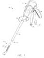
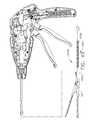
- FIGS. 1 and 2depict a surgical cutting and fastening instrument 10 according to various embodiments of the present invention.
- the illustrated embodimentis an endoscopic surgical instrument 10 and in general, the embodiments of the instrument 10 described herein are endoscopic surgical cutting and fastening instruments. It should be noted, however, that according to other embodiments of the present invention, the instrument 10 may be a non-endoscopic surgical cutting instrument, such as a laproscopic instrument.
- the surgical instrument 10 depicted in FIGS. 1 and 2comprises a handle 6, a shaft 8, and an articulating end effector 12 pivotally connected to the shaft 8 at an articulation pivot 14.
- An articulation control 16may be provided adjacent to the handle 6 to effect rotation of the end effector 12 about the articulation pivot 14. It will be appreciated that various embodiments may include a non-pivoting end effector, and therefore may not have an articulation pivot 14 or articulation control 16.
- the end effector 12is configured to act as an endocutter for clamping, severing and stapling tissue, although, in other embodiments, different types of end effectors may be used, such as end effectors for other types of surgical devices, such as graspers, cutters, staplers, clip appliers, access devices, drug/gene therapy devices, ultrasound, RF or laser devices, etc.
- the handle 6 of the instrument 10may include a closure trigger 18 and a firing trigger 20 for actuating the end effector 12. It will be appreciated that instruments having end effectors directed to different surgical tasks may have different numbers or types of triggers or other suitable controls for operating the end effector 12.
- the end effector 12is shown separated from the handle 6 by a preferably elongate shaft 8.
- a clinician or operator of the instrument 10may articulate the end effector 12 relative to the shaft 8 by utilizing the articulation control 16, as described in more detail in pending United States Patent Application Serial No. 11/329,020, filed January 10, 2006 , entitled "Surgical Instrument Having An Articulating End Effector," by Geoffrey C. Hueil et al., now U.S. Patent No. 7,670,334 which is incorporated herein by reference in its entirety.
- the end effector 12includes in this example, among other things, a staple channel 22 and a pivotally translatable clamping member, such as an anvil 24, which are maintained at a spacing that assures effective stapling and severing of tissue clamped in the end effector 12.
- the handle 6includes a pistol grip 26 toward which a closure trigger 18 is pivotally drawn by the clinician to cause clamping or closing of the anvil 24 towards the staple channel 22 of the end effector 12 to thereby clamp tissue positioned between the anvil 24 and channel 22.
- the firing trigger 20is farther outboard of the closure trigger 18. Once the closure trigger 18 is locked in the closure position as further described below, the firing trigger 20 may rotate slightly toward the pistol grip 26 so that it can be reached by the operator using one hand.
- the operatormay pivotally draw the firing trigger 20 toward the pistol grip 26 to cause the stapling and severing of clamped tissue in the end effector 12.
- different types of clamping members besides the anvil 24could be used, such as, for example, an opposing jaw, etc.
- proximal and distalare used herein with reference to a clinician gripping the handle 6 of an instrument 10.
- end effector 12is distal with respect to the more proximal handle 6.
- spatial termssuch as “vertical” and “horizontal” are used herein with respect to the drawings.
- surgical instrumentsare used in many orientations and positions, and these terms are not intended to be limiting and absolute.
- the closure trigger 18may be actuated first. Once the clinician is satisfied with the positioning of the end effector 12, the clinician may draw back the closure trigger 18 to its fully closed, locked position proximate to the pistol grip 26. The firing trigger 20 may then be actuated. The firing trigger 20 returns to the open position (shown in FIGS. 1 and 2 ) when the clinician removes pressure, as described more fully below. A release button on the handle 6, when depressed may release the locked closure trigger 18.
- the release buttonmay be implemented in various forms such as, for example, release button 30 shown in FIGS. 42-43 , slide release button 160 shown in FIG. 14 , and/or button 172 shown in FIG. 16 .
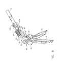
- FIGS. 3-6show embodiments of a rotary-driven end effector 12 and shaft 8 according to various embodiments.
- FIG. 3is an exploded view of the end effector 12 according to various embodiments.
- the end effector 12may include, in addition to the previously-mentioned channel 22 and anvil 24, a cutting instrument 32, a sled 33, a staple cartridge 34 that is removably seated in the channel 22, and a helical screw shaft 36.
- the cutting instrument 32may be, for example, a knife.
- the anvil 24may be pivotably opened and closed at pivot pins 25 connected to the proximate end of the channel 22.
- the anvil 24may also include a tab 27 at its proximate end that is inserted into a component of the mechanical closure system (described further below) to open and close the anvil 24.
- the closure trigger 18When the closure trigger 18 is actuated, that is, drawn in by a user of the instrument 10, the anvil 24 may pivot about the pivot pins 25 into the clamped or closed position. If clamping of the end effector 12 is satisfactory, the operator may actuate the firing trigger 20, which, as explained in more detail below, causes the knife 32 and sled 33 to travel longitudinally along the channel 22, thereby cutting tissue clamped within the end effector 12.
- the sled 33may be an integral component of the cartridge 34.
- United States Pat. No. 6,978,921entitled “Surgical Stapling Instrument Incorporating an E-Beam Firing Mechanism” to Shelton, IV et al.” which is incorporated herein by reference in its entirety, provides more details about such two-stroke cutting and fastening instruments.
- the sled 33may be part of the cartridge 34, such that when the knife 32 retracts following the cutting operation, the sled 33 does not retract.
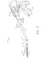
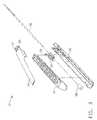
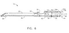
- FIGS. 4 and 5are exploded views and FIG. 6 is a side view of the end effector 12 and shaft 8 according to various embodiments.
- the shaft 8may include a proximate closure tube 40 and a distal closure tube 42 pivotably linked by a pivot link 44.
- the distal closure tube 42includes an opening 45 into which the tab 27 on the anvil 24 is inserted in order to open and close the anvil 24, as further described below.
- Disposed inside the closure tubes 40, 42may be a proximate spine tube 46.
- Disposed inside the proximate spine tube 46may be a main rotational (or proximate) drive shaft 48 that communicates with a secondary (or distal) drive shaft 50 via a bevel gear assembly 52.
- the secondary drive shaft 50is connected to a drive gear 54 that engages a proximate drive gear 56 of the helical screw shaft 36.
- the vertical bevel gear 52bmay sit and pivot in an opening 57 in the distal end of the proximate spine tube 46.
- a distal spine tube 58may be used to enclose the secondary drive shaft 50 and the drive gears 54, 56.
- a bearing 38positioned at a distal end of the staple channel 22, receives the helical drive screw 36, allowing the helical drive screw 36 to freely rotate with respect to the channel 22.
- the helical screw shaft 36may interface a threaded opening (not shown) of the knife 32 such that rotation of the shaft 36 causes the knife 32 to translate distally or proximately (depending on the direction of the rotation) through the staple channel 22.
- the bevel gear assembly 52a-ccauses the secondary drive shaft 50 to rotate, which in turn, because of the engagement of the drive gears 54, 56, causes the helical screw shaft 36 to rotate, which causes the knife driving member 32 to travel longitudinally along the channel 22 to cut any tissue clamped within the end effector 12.
- the sled 33may be made of, for example, plastic, and may have a sloped distal surface. As the sled 33 traverses the channel 22, the sloped forward surface may push up or drive the staples in the staple cartridge through the clamped tissue and against the anvil 24. The anvil 24 turns the staples, thereby stapling the severed tissue. When the knife 32 is retracted, the knife 32 and sled 33 may become disengaged, thereby leaving the sled 33 at the distal end of the channel 22.
- embodiments of the present inventionprovide a motor-driven endocutter with user-feedback of the deployment, force and/or position of the cutting instrument 32 in end effector 12.
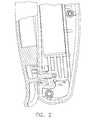
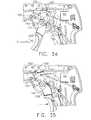
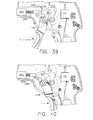
- FIGS. 7-10illustrate an exemplary embodiment of a motor-driven endocutter, and in particular the handle thereof, that provides user-feedback regarding the deployment and loading force of the cutting instrument 32 in the end effector 12.
- the embodimentmay use power provided by the user in retracting the firing trigger 20 to power the device (a so-called "power assist" mode).
- the embodimentmay be used with the rotary driven end effector 12 and shaft 8 embodiments described above.
- the handle 6includes exterior lower side pieces 59, 60 and exterior upper side pieces 61, 62 that fit together to form, in general, the exterior of the handle 6.
- a battery 64such as a Li ion battery, may be provided in the pistol grip portion 26 of the handle 6.
- the battery 64powers a motor 65 disposed in an upper portion of the pistol grip portion 26 of the handle 6.
- the motor 65may be a DC brushed driving motor having a maximum rotation of, approximately, 5000 RPM.
- the motor 65may drive a 90° bevel gear assembly 66 comprising a first bevel gear 68 and a second bevel gear 70.
- the bevel gear assembly 66may drive a planetary gear assembly 72.
- the planetary gear assembly 72may include a pinion gear 74 connected to a drive shaft 76.
- the pinion gear 74may drive a mating ring gear 78 that drives a helical gear drum 80 via a drive shaft 82.
- a ring 84may be threaded on the helical gear drum 80.
- the handle 6may also include a run motor sensor 110 (see FIG. 10 ) in communication with the firing trigger 20 to detect when the firing trigger 20 has been drawn in (or "closed") toward the pistol grip portion 26 of the handle 6 by the operator to thereby actuate the cutting/stapling operation by the end effector 12.
- the sensor 110may be a proportional sensor such as, for example, a rheostat or variable resistor. When the firing trigger 20 is drawn in, the sensor 110 detects the movement, and sends an electrical signal indicative of the voltage (or power) to be supplied to the motor 65. When the sensor 110 is a variable resistor or the like, the rotation of the motor 65 may be generally proportional to the amount of movement of the firing trigger 20.
- the rotation of the motor 65is relatively low.
- the rotation of the motor 65is at its maximum. In other words, the harder the user pulls on the firing trigger 20, the more voltage is applied to the motor 65, causing greater rates of rotation.
- the handle 6may include a middle handle piece 104 adjacent to the upper portion of the firing trigger 20.
- the handle 6also may comprise a bias spring 112 connected between posts on the middle handle piece 104 and the firing trigger 20.
- the bias spring 112may bias the firing trigger 20 to its fully open position. In that way, when the operator releases the firing trigger 20, the bias spring 112 will pull the firing trigger 20 to its open position, thereby removing actuation of the sensor 110, thereby stopping rotation of the motor 65.
- the bias spring 112any time a user closes the firing trigger 20, the user will experience resistance to the closing operation, thereby providing the user with feedback as to the amount of rotation exerted by the motor 65.
- the operatorcould stop retracting the firing trigger 20 to thereby remove force from the sensor 100, to thereby stop the motor 65.
- the usermay stop the deployment of the end effector 12, thereby providing a measure of control of the cutting/fastening operation to the operator.
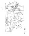
- the distal end of the helical gear drum 80includes a distal drive shaft 120 that drives a ring gear 122, which mates with a pinion gear 124.
- the pinion gear 124is connected to the main drive shaft 48 of the main drive shaft assembly. In that way, rotation of the motor 65 causes the main drive shaft assembly to rotate, which causes actuation of the end effector 12, as described above.
- the ring 84 threaded on the helical gear drum 80may include a post 86 that is disposed within a slot 88 of a slotted arm 90.
- the slotted arm 90has an opening 92 its opposite end 94 that receives a pivot pin 96 that is connected between the handle exterior side pieces 59, 60.
- the pivot pin 96is also disposed through an opening 100 in the firing trigger 20 and an opening 102 in the middle handle piece 104.
- the handle 6may include a reverse motor sensor (or end-of-stroke sensor) 130 and a stop motor (or beginning-of-stroke) sensor 142.
- the reverse motor sensor 130may be a limit switch located at the distal end of the helical gear drum 80 such that the ring 84 threaded on the helical gear drum 80 contacts and trips the reverse motor sensor 130 when the ring 84 reaches the distal end of the helical gear drum 80.
- the reverse motor sensor 130when activated, sends a signal to the motor 65 to reverse its rotation direction, thereby withdrawing the knife 32 of the end effector 12 following the cutting operation.
- the stop motor sensor 142may be, for example, a normally-closed limit switch. In various embodiments, it may be located at the proximate end of the helical gear drum 80 so that the ring 84 trips the switch 142 when the ring 84 reaches the proximate end of the helical gear drum 80.
- the sensor 110detects the deployment of the firing trigger 20 and sends a signal to the motor 65 to cause forward rotation of the motor 65, for example, at a rate proportional to how hard the operator pulls back the firing trigger 20.
- the forward rotation of the motor 65in turn causes the ring gear 78 at the distal end of the planetary gear assembly 72 to rotate, thereby causing the helical gear drum 80 to rotate, causing the ring 84 threaded on the helical gear drum 80 to travel distally along the helical gear drum 80.
- the rotation of the helical gear drum 80also drives the main drive shaft assembly as described above, which in turn causes deployment of the knife 32 in the end effector 12.
- the knife 32 and sled 33are caused to traverse the channel 22 longitudinally, thereby cutting tissue clamped in the end effector 12. Also, the stapling operation of the end effector 12 is caused to happen in embodiments where a stapling-type end effector 12 is used.
- the ring 84 on the helical gear drum 80will have reached the distal end of the helical gear drum 80, thereby causing the reverse motor sensor 130 to be tripped, which sends a signal to the motor 65 to cause the motor 65 to reverse its rotation. This in turn causes the knife 32 to retract, and also causes the ring 84 on the helical gear drum 80 to move back to the proximate end of the helical gear drum 80.
- the middle handle piece 104includes a backside shoulder 106 that engages the slotted arm 90 as best shown in FIGS. 8 and 9 .
- the middle handle piece 104also has a forward motion stop 107 that engages the firing trigger 20.
- the movement of the slotted arm 90is controlled, as explained above, by rotation of the motor 65.
- the middle handle piece 104will be free to rotate counter clockwise.
- the firing trigger 20will engage the forward motion stop 107 of the middle handle piece 104, causing the middle handle piece 104 to rotate counter clockwise.
- the middle handle piece 104will only be able to rotate counter clockwise as far as the slotted arm 90 permits. In that way, if the motor 65 should stop rotating for some reason, the slotted arm 90 will stop rotating, and the user will not be able to further draw in the firing trigger 20 because the middle handle piece 104 will not be free to rotate counter clockwise due to the slotted arm 90.
- FIGS. 10A and 10Billustrate two states of a variable sensor that may be used as the run motor sensor 110 according to various embodiments of the present invention.
- the sensor 110may include a face portion 280, a first electrode (A) 282, a second electrode (B) 284, and a compressible dielectric material 286 between the electrodes 282, 284, such as, for example, an electroactive polymer (EAP).
- EAPelectroactive polymer
- the sensor 110may be positioned such that the face portion 280 contacts the firing trigger 20 when retracted. Accordingly, when the firing trigger 20 is retracted, the dielectric material 286 is compressed, as shown in FIG. 10B , such that the electrodes 282, 284 are closer together.
- the distance “b" between the electrodes 282, 284is directly related to the impedance between the electrodes 282, 284, the greater the distance the more impedance, and the closer the distance the less impedance. In that way, the amount that the dielectric 286 is compressed due to retraction of the firing trigger 20 is proportional to the impedance between the electrodes 282, 284, which can be used to proportionally control the motor 65.
- FIGS. 7-10Components of an exemplary closure system for closing (or clamping) the anvil 24 of the end effector 12 by retracting the closure trigger 18 are also shown in FIGS. 7-10 .
- the closure systemincludes a yoke 250 connected to the closure trigger 18 by a pivot pin 251 inserted through aligned openings in both the closure trigger 18 and the yoke 250.
- a pivot pin 252, about which the closure trigger 18 pivots,is inserted through another opening in the closure trigger 18 which is offset from where the pin 251 is inserted through the closure trigger 18.
- retraction of the closure trigger 18causes the upper part of the closure trigger 18, to which the yoke 250 is attached via the pin 251, to rotate counterclockwise.
- the distal end of the yoke 250is connected, via a pin 254, to a first closure bracket 256.
- the first closure bracket 256connects to a second closure bracket 258.
- the closure brackets 256, 258define an opening in which the proximate end of the proximate closure tube 40 (see FIG. 4 ) is seated and held such that longitudinal movement of the closure brackets 256, 258 causes longitudinal motion by the proximate closure tube 40.
- the instrument 10also includes a closure rod 260 disposed inside the proximate closure tube 40.
- the closure rod 260may include a window 261 into which a post 263 on one of the handle exterior pieces, such as exterior lower side piece 59 in the illustrated embodiment, is disposed to fixedly connect the closure rod 260 to the handle 6. In that way, the proximate closure tube 40 is capable of moving longitudinally relative to the closure rod 260.
- the closure rod 260may also include a distal collar 267 that fits into a cavity 269 in proximate spine tube 46 and is retained therein by a cap 271 (see FIG. 4 ).
- the closure brackets 256, 258cause the proximate closure tube 40 to move distally (i.e., away from the handle end of the instrument 10), which causes the distal closure tube 42 to move distally, which causes the anvil 24 to rotate about the pivot pins 25 into the clamped or closed position.
- the closure trigger 18is unlocked from the locked position, the proximate closure tube 40 is caused to slide proximately, which causes the distal closure tube 42 to slide proximately, which, by virtue of the tab 27 being inserted in the window 45 of the distal closure tube 42, causes the anvil 24 to pivot about the pivot pins 25 into the open or unclamped position.
- an operatormay clamp tissue between the anvil 24 and channel 22, and may unclamp the tissue following the cutting/stapling operation by unlocking the closure trigger 20 from the locked position.
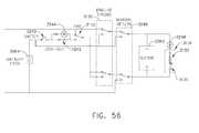
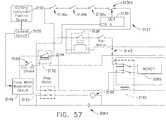
- FIG. 11is a schematic diagram of an electrical circuit of the instrument 10 according to various embodiments of the present invention.
- the sensor 110When an operator initially pulls in the firing trigger 20 after locking the closure trigger 18, the sensor 110 is activated, allowing current to flow therethrough. If the normally-open reverse motor sensor switch 130 is open (meaning the end of the end effector stroke has not been reached), current will flow to a single pole, double throw relay 132. Since the reverse motor sensor switch 130 is not closed, the inductor 134 of the relay 132 will not be energized, so the relay 132 will be in its non-energized state.
- the circuitalso includes a cartridge lockout sensor 136. If the end effector 12 includes a staple cartridge 34, the sensor 136 will be in the closed state, allowing current to flow. Otherwise, if the end effector 12 does not include a staple cartridge 34, the sensor 136 will be open, thereby preventing the battery 64 from powering the motor 65.
- the sensor 136When the staple cartridge 34 is present, the sensor 136 is closed, which energizes a single pole, single throw relay 138. When the relay 138 is energized, current flows through the relay 136, through the variable resistor sensor 110, and to the motor 65 via a double pole, double throw relay 140, thereby powering the motor 65 and allowing it to rotate in the forward direction.
- the reverse motor sensor 130When the end effector 12 reaches the end of its stroke, the reverse motor sensor 130 will be activated, thereby closing the switch 130 and energizing the relay 134. This causes the relay 134 to assume its energized state (not shown in FIG. 13 ), which causes current to bypass the cartridge lockout sensor 136 and variable resistor 110, and instead causes current to flow to both the normally-closed double pole, double throw relay 140 and back to the motor 65, but in a manner, via the relay 140, that causes the motor 65 to reverse its rotational direction.
- stop motor sensor switch 142Because the stop motor sensor switch 142 is normally-closed, current will flow back to the relay 134 to keep it closed until the switch 142 opens. When the knife 32 is fully retracted, the stop motor sensor switch 142 is activated, causing the switch 142 to open, thereby removing power from the motor 65.
- an on-off type sensorcould be used.
- the rate of rotation of the motor 65would not be proportional to the force applied by the operator. Rather, the motor 65 would generally rotate at a constant rate. But the operator would still experience force feedback because the firing trigger 20 is geared into the gear drive train.
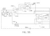
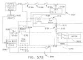
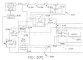
- FIG. 11Ais a schematic diagram of another electrical circuit of the instrument 10 according to various embodiments of the present invention.
- This electrical circuitincludes lockout sensor switches 136a-d collectively defining an interlock circuit 137 through which current from the relay 132, when de-energized, must pass in order for electrical operation of the motor 65 to be initiated.
- Each lockout sensor switch 136a-dis configured to maintain an open (i.e., non-conductive) switch state or a closed (i.e., conductive) switch state responsive to the presence or absence, respectively, of a corresponding condition. Any of the corresponding conditions, if present when the instrument 10 is fired, may result in an unsatisfactory cutting and stapling operation and/or damage to the instrument 10.
- Conditions to which the lockout sensor switches 136a-d may respondinclude, for example, the absence of the staple cartridge 34 in the channel 22, the presence of a spent (e.g., previously fired) staple cartridge 34 in the channel 22, and an open (or otherwise insufficiently closed) position of the anvil 24 with respect to the channel 22.
- Other conditions to which the lockout sensor switches 136a-d may respondsuch as component wear, may be inferred based upon an accumulated number of firing operations produced by the instrument 10. Accordingly, if any of these conditions exists, the corresponding lockout sensor switches 136a-d maintain an open switch state, thus preventing passage of the current necessary to initiate operation of the motor 65. Passage of current by the lockout sensors 136a-d is allowed only after all of the conditions have been remedied.
- the lockout sensor switch 136amay be implemented using a normally-open switch configuration such that a closed switch state is maintained when the staple cartridge 34 is in a position corresponding to its proper receipt by the channel 22.
- the lockout sensor switch 136amaintains an open switch state.
- Lockout sensor switch 136bmay be implemented using a normally-open switch configuration such that a closed switch state is maintained only when an unspent staple cartridge 34 (i.e., a staple cartridge 34 having a sled 33 in the unfired position) is present in the channel 22. The presence of a spent staple cartridge 34 in the channel 22 causes the lockout sensor switch 136b to maintain an open switch state.
- an unspent staple cartridge 34i.e., a staple cartridge 34 having a sled 33 in the unfired position
- Lockout sensor switch 136cmay be implemented using a normally-open switch configuration such that a closed switch state is maintained when the anvil 24 is in a closed position with respect to the channel 22. As discussed in further detail below, the lockout sensor switch 136c may be controlled in accordance with a time delay feature wherein a closed switch state is maintained only after the anvil 24 is in the closed position for a predetermined period of time.
- Lockout sensor switch 136dmay be implemented using a normally-closed switch configuration such that a closed switch state is maintained only when an accumulated number of firings produced by the instrument 10 is less than a pre-determined number. As discussed in further detail below, the lockout sensor switch 136d may be in communication with a counter 304 configured for maintaining a count representative of the accumulated number of firing operations performed by the instrument, comparing the count to the pre-determined number, and controlling the switch state of the lockout sensor switch 136d based upon the comparison.
- the interlock circuit 137may comprise one or more indicators visible to the user of the instrument 10 for displaying a status of at least one of the lockout sensor switches 136a-c. As shown in FIG. 11A , for example, each lockout sensor switch 136a-d may have a green LED 139a and a red LED 139b associated therewith. The interlock circuit 137 may be configured such that the LEDs 139a,b are energized when the corresponding lockout sensor switch 136a-d is maintained in the closed and open switch states, respectively. It will be appreciated that the lockout sensor switches 136a-d may comprise one or more auxiliary switch contacts (not shown) having a switch configuration suitable for operating the LEDs 139a,b in the manner described above.
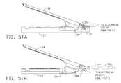
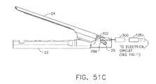
- FIGS. 50A-51Cillustrate mounting arrangements and configurations of the lockout sensor switches 136a-d of the interlock circuit 137 according to various embodiments of the present invention.
- the lockout sensor switch 136amay comprise a first switch contact 288a and a second switch contact 288b disposed upon an inner wall of the channel 22 and electrically isolated therefrom.
- the respective positions of the first and second switch contacts 288a,bare such that when the staple cartridge 34 is in a position corresponding to its proper receipt by the channel 22, a conductive or semi-conductive portion 290 of the staple cartridge 34 (exemplified as a metal tray portion of the staple cartridge 34) contacts the first and second switch contacts 288a,b to establish a conductive path therebetween.
- each switch contact 288a,bmay comprise a rounded profile for minimizing mechanical resistance to the staple cartridge 34 when received by the channel 22 and for enabling affirmative electrical contact with the conductive portion 290 thereof.
- the conductive portion 290thus operates to maintain the lockout sensor switch 136a in a closed switch state.
- the switch contacts 288a,bare shown adjacently positioned on a sidewall portion of the channel 22, it will be appreciated that each switch contact 288a,b may generally be located at any location within the channel 22 where suitable electrical contact with the conductive member 290 is possible. It will further be appreciated that the lockout sensor switch 136a may alternatively be implemented using a conventional contact-actuated limit switch.
- the limit switchmay be positioned such that staple cartridge 34, when received by the channel 22, mechanically actuates the limit switch such that a closed switch state is maintained.
- the lockout sensor switch 136amay also be implemented using a conventional non-contact actuated limit switch, such as, for example, a magnetic reed limit switch or a Hall effect proximity switch.
- the staple cartridge 34may comprise a magnet suitable for causing the lockout sensor switch 136a to maintain a closed switch state when the staple cartridge 34 is installed.
- the lockout sensor switch 136bmay be mounted on an interior bottom surface of the channel 22.
- the lockout sensor switch 136bmay be implemented using a contact-actuated limit switch of a conventional design that is suitable for detecting linear movement. Orientation of the lockout sensor switch 136b may be such that an actuated portion thereof extends upwardly from the bottom interior surface of the channel 22.
- the position of the lockout sensor switch 136b on the bottom surface of the channel 22is such that when an unspent staple cartridge 34 is installed, a bottom portion of the sled 33 mechanically actuates the lockout sensor switch 136b and causes a closed switch state to be maintained thereby.
- an unspent staple cartridge 34i.e., a staple cartridge having a sled 33 in the unfired position
- the lockout sensor switch 136bmay instead be implemented using a non-contact actuated switch (e.g., a magnetic reed limit switch or a Hall effect proximity switch).
- the sled 33may comprise a magnetized portion, for example, that actuates the lockout sensor switch 136b when the sled 33 is present in the un-fired position.
- the lockout sensor switch 136cis positioned adjacent a distal end of one of the pivot recesses 296 defined by the proximal end of the channel 22 for engaging a corresponding pivot point 25 of the anvil 24.
- the lockout sensor switch 136cmay be implemented using a contact-actuated limit switch of a conventional design that is suitable for detecting linear movement. It will be appreciated, however, that a non-contact-actuated limit switch may be used instead. Orientation of the lockout sensor switch 136c may be such that an actuated portion thereof extends slightly over the distal end of the corresponding pivot recess 296.
- the pivot point 25When the anvil 24 is in an open position with respect to the channel 22 (as shown in FIG. 51A ), the pivot point 25 is positioned at the proximal end of the pivot recess 296. Closure of the anvil 24 causes the pivot point 25 to move to the distal end of the pivot recess 296. The resulting contact of the pivot point 25 with the actuated portion of the lockout sensor switch 136c causes the lockout sensor switch 136c to maintain a closed switch state, thus enabling the passage of current therethrough.
- the lockout sensor switch 136cmay instead be configured to maintain a closed switch state responsive to an electrical signal.
- the electrical signalmay be, for example, an analog signal generated by a force sensor 298 disposed on a bottom inner surface of the channel 22 that represents a magnitude of the clamping force applied by the anvil 24.
- the closed position of the anvil 24may thus be inferred if the analog signal is sufficiently large in magnitude.
- the analog signalmay be received by a comparator circuit 141 configured to determine if the magnitude exceeds a pre-determined threshold stored therein.
- the comparator circuit 141causes the lockout sensor switch 136c to maintain a closed switch state, thus enabling the passage of current therethrough. If the magnitude of the analog signal is less than the pre-determined threshold, indicating that the anvil 24 is not sufficiently closed, the comparator circuit 141 causes the lockout sensor switch 136c to maintain an open switch state, thus preventing the passage of current therethrough.
- the comparator circuit 141may be integral with the lockout sensor switch 136c so as to form a common device. It will further be appreciated that the pre-defined threshold stored by the comparator circuit 141 may be adjusted as necessary to reflect the force indicative of closure of the anvil 24 for different cutting and stapling operations.
- embodiments of the present inventionmay comprise a timer 300 having a pre-set time delay (e.g., 12 seconds) and configured for controlling the switch state of the lockout sensor switch 136c in accordance with a time-based position of the anvil 24.
- a pre-set time delaye.g. 12 seconds
- the timer 300may be integral with the lockout sensor switch 136c so as to form a common device (e.g., an on-delay timer).
- the timer 300is implemented as an electronic device, although it will be appreciated that a mechanical timer may be used instead.
- a normally-open limit switch 302configured in a manner identical to that of FIG. 51A may be connected to the timer 300 such that timing is initiated when the anvil 24 is in a closed position with respect to the channel 22.
- the timer 300Upon expiration of the pre-set time delay, the timer 300 causes the lockout sensor switch 136c to maintain a closed switch state, thus enabling the passage of current therethrough.
- the timer 300may be reset in response to the transition of the limit switch 302 to an open switch state (i.e., when the anvil 24 is in the open position).
- the pre-set time delay of the timer 300may be selectively adjusted (e.g., using an integral potentiometer adjustment) as required.
- the electrical circuitmay comprise a counter 304 configured to maintain a count representative of the accumulated number of firing operations performed by the instrument 10 and, based on the count, to control the switch state of the lockout sensor switch 136d.
- counter 304may be integral with the lockout sensor switch 136d so as to form a common device.
- the counter 304is implemented as an electronic device having an input for incrementing the maintained count based upon the transition of a discrete electrical signal provided thereto.
- a mechanical counterconfigured for maintaining the count based upon a mechanical input (e.g., retraction of the firing trigger 20) may be used instead.
- any discrete signal present in the electrical circuit that transitions once for each firing operationmay be utilized for the counter 304 input.
- the discrete electrical signal resulting from actuation of the end-of-stroke sensor 130may be utilized.
- the counter 304may control the switch state of lockout sensor switch 136d such that a closed switch state is maintained when the maintained count is less than a pre-determined number stored within the counter 304.
- the counter 304causes the lockout sensor switch 136d to maintain an open switch state, thus preventing the passage of current therethrough.
- the pre-determined number stored by the counter 304may be selectively adjusted as required.
- the counter 304may be in communication with a display 305, such as an LCD display, integral to the instrument 10 for indicating to a user either the maintained count or the difference between the pre-determined number and the maintained count.
- a single pole, single throw relay 138When the lockout sensor switches 136a-d collectively maintain a closed switch state, a single pole, single throw relay 138 is energized. When the relay 138 is energized, current flows through the relay 138, through the variable resistor sensor 110, and to the motor 65 via a double pole, double throw relay 140, thereby powering the motor 65 and allowing it to rotate in the forward direction. Because the output of the relay 138, once energized, maintains the relay 138 in an energized state until relay 132 is energized, the interlock circuit 137 will not function to prevent operation of the motor 165 once initiated, even if one or more of the interlock sensor switches 136a-d subsequently maintains an open switch state. In other embodiments, however, it may be necessary or otherwise desirable to connect the interlock circuit 137 and the relay 138 such that one or more the lockout sensor switches 136a-d must maintain a closed switch state in order to sustain operation of the motor 165 once initiated.
- solenoid 306is energized.
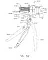
- the solenoid 306may be a conventional push-type solenoid that, when energized, causes a plunger (not shown) to be axially extended. As discussed below in connection with FIGS. 14-22 , extension of the plunger may operate to retain the closure trigger 18 in the retracted position, thus preventing the anvil 24 from opening while a firing operation is in progress (i.e., while the switch 142 is not actuated).
- the plungeris retracted such that manual release of the closure trigger 18 is possible.
- the reverse motor sensor 130When the end effector 12 reaches the end of its stroke, the reverse motor sensor 130 will be activated, thereby closing the switch 130 and energizing the relay 132. This causes the relay 132 to assume its energized state, which causes current to bypass the interlock circuit 137 and variable resistor 110, and instead causes current to flow to both the normally-closed double pole, double throw relay 140 and back to the motor 65, but in a manner, via the relay 140, that causes the motor 65 to reverse its rotational direction.
- stop motor sensor switch 142Because the stop motor sensor switch 142 is normally-closed, current will flow back to the relay 132 to keep it energized until the switch 142 opens. When the knife 32 is fully retracted, the stop motor sensor switch 142 is activated, causing the switch 142 to open, thereby removing power from the motor 65 and de-energizing the solenoid 306.
- an on-off type sensorcould be used.
- the rate of rotation of the motor 65would not be proportional to the force applied by the operator. Rather, the motor 65 would generally rotate at a constant rate. But the operator would still experience force feedback because the firing trigger 20 is geared into the gear drive train.
- FIG. 12is a side-view of the handle 6 of a power-assist motorized endocutter according to another embodiment.
- the embodiment of FIG. 12is similar to that of FIGS. 7-10 except that in the embodiment of FIG. 12 , there is no slotted arm connected to the ring 84 threaded on the helical gear drum 80.
- the ring 84includes a sensor portion 114 that moves with the ring 84 as the ring 84 advances down (and back) on the helical gear drum 80.
- the sensor portion 114includes a notch 116.
- the reverse motor sensor 130may be located at the distal end of the notch 116 and the stop motor sensor 142 may be located at the proximate end of the notch 116.
- the middle piece 104may have an arm 118 that extends into the notch 12.
- the run motor sensor 110detects the motion and sends a signal to power the motor 65, which causes, among other things, the helical gear drum 80 to rotate.
- the ring 84 threaded on the helical gear drum 80advances (or retracts, depending on the rotation).
- the middle piece 104is caused to rotate counter clockwise with the firing trigger 20 due to the forward motion stop 107 that engages the firing trigger 20.
- the counter clockwise rotation of the middle piece 104cause the arm 118 to rotate counter clockwise with the sensor portion 114 of the ring 84 such that the arm 118 stays disposed in the notch 116.
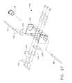
- FIG. 13is a side-view of the handle 6 of a power-assist motorized endocutter according to another embodiment.
- the embodiment of FIG. 13is similar to that of FIGS. 7-10 except that in the embodiment of FIG. 13 , there is no slot in the arm 90.
- the ring 84 threaded on the helical gear drum 80includes a vertical channel 126.
- the arm 90includes a post 128 that is disposed in the channel 126.
- the ring 84 threaded on the helical gear drum 80advances (or retracts, depending on the rotation).
- the arm 90rotates counter clockwise as the ring 84 advances due to the post 128 being disposed in the channel 126, as shown in FIG. 13 .
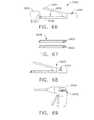
- FIGS. 14 and 15show one embodiment of a way to lock the closure trigger 18 to the pistol grip portion 26 of the handle 6.
- the pistol grip portion 26includes a hook 150 that is biased to rotate CCW about a pivot point 151 by a torsion spring 152.
- the closure trigger 18includes a closure bar 154. As the operator draws in the closure trigger 18, the closure bar 154 engages a sloped portion 156 of the hook 150, thereby rotating the hook 150 upward (or CW in FIGS.
- the closure bar 154may be positioned within the pistol grip 26 such that the plunger 308 of the solenoid 306, when energized, is received into a corresponding opening 163 of the slide button release 160. Accordingly, the slide button release 160 is locked in place such that manipulation of the slide button release 160 is prevented until the plunger 308 is retracted from the opening 163 at the conclusion of the firing operation.
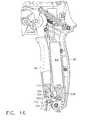
- FIG. 16shows another closure trigger locking mechanism according to various embodiments.
- the closure trigger 18includes a wedge 160 having an arrow-head portion 161.
- the arrow-head portion 161is biased downward (or clockwise) by a leaf spring 162.
- the wedge 160 and leaf spring 162may be made from, for example, molded plastic.
- the arrow-head portion 161is inserted through an opening 164 in the pistol grip portion 26 of the handle 6.
- a lower chamfered surface 166 of the arrow-head portion 161engages a lower sidewall 168 of the opening 164, forcing the arrow-head portion 161 to rotate counter clockwise.
- the solenoid 306may be positioned within the pistol grip 26 such that the plunger 308 of the solenoid 306, when energized, is received into a corresponding opening 173 defined by the arrow-head portion 161. When received into the opening 173, the plunger 308 operates to prevent CCW rotation of the arrow-head portion 161. Accordingly, inadvertent manipulation of the button 172 by the user is prevented by the user until the plunger 308 is retracted from the opening 173 at the conclusion of the firing operation.
- FIGS. 17-22show a closure trigger locking mechanism according to another embodiment.
- the closure trigger 18includes a flexible longitudinal arm 176 that includes a lateral pin 178 extending therefrom.
- the arm 176 and pin 178may be made from molded plastic, for example.
- the pistol grip portion 26 of the handle 6includes an opening 180 with a laterally extending wedge 182 disposed therein.
- the pin 178engages the wedge 182, and the pin 178 is forced downward (i.e., the arm 176 is rotated clockwise) by the lower surface 184 of the wedge 182, as shown in FIGS. 17 and 18 .
- the operatormay further squeeze the closure trigger 18, causing the pin 178 to engage a sloped backwall 190 of the opening 180, forcing the pin 178 upward past the flexible stop 188, as shown in FIGS. 20 and 21 .
- the pin 178is then free to travel out an upper channel 192 in the opening 180 such that the closure trigger 18 is no longer locked to the pistol grip portion 26, as shown in FIG. 22 .
- the solenoid 306may be positioned within the pistol grip 26 such that the plunger 308 of the solenoid 306, when energized, is received into the upper channel 192. When received into the upper channel 192, the plunger 308 operates to prevent passage of the pin 178 therethrough. Accordingly, unlocking the closure trigger 18 is prevented until the plunger 308 is retracted from the upper channel 192 at the conclusion of the firing operation.
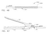
- FIGS. 23A-Bshow a universal joint ("u-joint") 195.
- the second piece 195-2 of the u-joint 195rotates in a horizontal plane in which the first piece 195-1 lies.
- FIG. 23Ashows the u-joint 195 in a linear (180°) orientation and
- FIG. 23Bshows the u-joint 195 at approximately a 150° orientation.
- the u-joint 195may be used instead of the bevel gears 52a-c (see FIG. 4 , for example) at the articulation point 14 of the main drive shaft assembly to articulate the end effector 12.
- FIGS. 24A-Bshow a torsion cable 197 that may be used in lieu of both the bevel gears 52a-c and the u-joint 195 to realize articulation of the end effector 12.
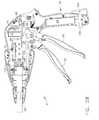
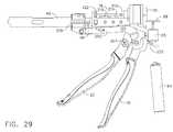
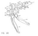
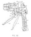
- FIGS. 25-31illustrate another embodiment of a motorized, two-stroke surgical cutting and fastening instrument 10 with power assist according to another embodiment of the present invention.
- the embodiment of FIGS. 25-31is similar to that of FIGS. 6-10 except that instead of the helical gear drum 80, the embodiment of FIGS. 23-28 includes an alternative gear drive assembly.
- the embodiment of FIGS. 25-31includes a gear box assembly 200 including a number of gears disposed in a frame 201, wherein the gears are connected between the planetary gear 72 and the pinion gear 124 at the proximate end of the drive shaft 48.
- the gear box assembly 200provides feedback to the user via the firing trigger 20 regarding the deployment and loading force of the end effector 12.
- the usermay provide power to the system via the gear box assembly 200 to assist the deployment of the end effector 12.
- the embodiment of FIGS. 23-32is another power assist motorized instrument 10 that provides feedback to the user regarding the loading force experienced by the instrument.
- the firing trigger 20includes two pieces: a main body portion 202 and a stiffening portion 204.
- the main body portion 202may be made of plastic, for example, and the stiffening portion 204 may be made out of a more rigid material, such as metal.
- the stiffening portion 204is adjacent to the main body portion 202, but according to other embodiments, the stiffening portion 204 could be disposed inside the main body portion 202.
- a pivot pin 207may be inserted through openings in the firing trigger pieces 202, 204 and may be the point about which the firing trigger 20 rotates.
- a spring 222may bias the firing trigger 20 to rotate in a counter clockwise direction.
- the spring 222may have a distal end connected to a pin 224 that is connected to the pieces 202, 204 of the firing trigger 20.
- the proximate end of the spring 222may be connected to one of the handle exterior lower side pieces 59, 60.
- both the main body portion 202 and the stiffening portion 204includes gear portions 206, 208 (respectively) at their upper end portions.
- the gear portions 206, 208engage a gear in the gear box assembly 200, as explained below, to drive the main drive shaft assembly and to provide feedback to the user regarding the deployment of the end effector 12.
- the gear box assembly 200may include as shown, in the illustrated embodiment, six (6) gears.
- a first gear 210 of the gear box assembly 200engages the gear portions 206, 208 of the firing trigger 20.
- the first gear 210engages a smaller second gear 212, the smaller second gear 212 being coaxial with a large third gear 214.
- the third gear 214engages a smaller fourth gear 216, the smaller fourth gear being coaxial with a fifth gear 218.
- the fifth gear 218is a 90° bevel gear that engages a mating 90° bevel gear 220 (best shown in FIG. 31 ) that is connected to the pinion gear 124 that drives the main drive shaft 48.
- a run motor sensor(not shown) is activated, which may provide a signal to the motor 65 to rotate at a rate proportional to the extent or force with which the operator is retracting the firing trigger 20. This causes the motor 65 to rotate at a speed proportional to the signal from the sensor.
- the sensoris not shown for this embodiment, but it could be similar to the run motor sensor 110 described above. The sensor could be located in the handle 6 such that it is depressed when the firing trigger 20 is retracted. Also, instead of a proportional-type sensor, an on/off type sensor may be used.
- Rotation of the motor 65causes the bevel gears 68, 70 to rotate, which causes the planetary gear 72 to rotate, which causes, via the drive shaft 76, the ring gear 122 to rotate.
- the ring gear 122meshes with the pinion gear 124, which is connected to the main drive shaft 48.
- rotation of the pinion gear 124drives the main drive shaft 48, which causes actuation of the cutting/stapling operation of the end effector 12.
- the usercan apply force (either in lieu of or in addition to the force from the motor 65) to actuate the main drive shaft assembly (and hence the cutting/stapling operation of the end effector 12) through retracting the firing trigger 20. That is, retracting the firing trigger 20 causes the gear portions 206, 208 to rotate counter clockwise, which causes the gears of the gear box assembly 200 to rotate, thereby causing the pinion gear 124 to rotate, which causes the main drive shaft 48 to rotate.
- the instrument 10may further include reverse motor and stop motor sensors.
- the reverse motor and stop motor sensorsmay detect, respectively, the end of the cutting stroke (full deployment of the knife 32) and the end of retraction operation (full retraction of the knife 32).
- a similar circuit to that described above in connection with FIG. 11may be used to appropriately power the motor 65.
- FIGS. 32-36illustrate a two-stroke, motorized surgical cutting and fastening instrument 10 with power assist according to another embodiment.
- the embodiment of FIGS. 32-36is similar to that of FIGS. 25-31 except that in the embodiment of FIGS. 32-36 , the firing trigger 20 includes a lower portion 228 and an upper portion 230. Both portions 228, 230 are connected to and pivot about a pivot pin 207 that is disposed through each portion 228, 230.
- the upper portion 230includes a gear portion 232 that engages the first gear 210 of the gear box assembly 200.
- the spring 222is connected to the upper portion 230 such that the upper portion is biased to rotate in the clockwise direction.
- the upper portion 230may also include a lower arm 234 that contacts an upper surface of the lower portion 228 of the firing trigger 20 such that when the upper portion 230 is caused to rotate clockwise the lower portion 228 also rotates clockwise, and when the lower portion 228 rotates counter clockwise the upper portion 230 also rotates counter clockwise.
- the lower portion 228includes a rotational stop 238 that engages a shoulder of the upper portion 230. In that way, when the upper portion 230 is caused to rotate counter clockwise the lower portion 228 also rotates counter clockwise, and when the lower portion 228 rotates clockwise the upper portion 230 also rotates clockwise.
- the illustrated embodimentalso includes the run motor sensor 110 that communicates a signal to the motor 65 that, in various embodiments, may cause the motor 65 to rotate at a speed proportional to the force applied by the operator when retracting the firing trigger 20.
- the sensor 110may be, for example, a rheostat or some other variable resistance sensor, as explained herein.
- the instrument 10may include reverse motor sensor 130 that is tripped or switched when contacted by a front face 242 of the upper portion 230 of the firing trigger 20. When activated, the reverse motor sensor 130 sends a signal to the motor 65 to reverse direction.
- the instrument 10may include a stop motor sensor 142 that is tripped or actuated when contacted by the lower portion 228 of the firing trigger 20. When activated, the stop motor sensor 142 sends a signal to stop the reverse rotation of the motor 65.
- the firing trigger 20In operation, when an operator retracts the closure trigger 18 into the locked position, the firing trigger 20 is retracted slightly (through mechanisms known in the art, including United States Patent No. 6,978,921 to Frederick Shelton, IV et. al and United States Patent No. 6,905,057 to Jeffery S. Swayze et. al, which are incorporated herein by reference) so that the user can grasp the firing trigger 20 to initiate the cutting/stapling operation, as shown in FIGS. 32 and 33 . At that point, as shown in FIG. 33 , the gear portion 232 of the upper portion 230 of the firing trigger 20 moves into engagement with the first gear 210 of the gear box assembly 200.
- the firing trigger 20may rotate a small amount, such as five degrees, before tripping the run motor sensor 110, as shown in FIG. 34 .
- Activation of the sensor 110causes the motor 65 to forward rotate at a rate proportional to the retraction force applied by the operator.
- the forward rotation of the motor 65causes, as described above, the main drive shaft 48 to rotate, which causes the knife 32 in the end effector 12 to be deployed (i.e., begin traversing the channel 22).
- Rotation of the pinion gear 124which is connected to the main drive shaft 48, causes the gears 210-220 in the gear box assembly 200 to rotate. Since the first gear 210 is in engagement with the gear portion 232 of the upper portion 230 of the firing trigger 20, the upper portion 232 is caused to rotate counter clockwise, which causes the lower portion 228 to also rotate counter clockwise.
- the front face 242 of the upper portion 230trips the reverse motor sensor 130, which sends a signal to the motor 65 to reverse rotational directional.
- Thiscauses the main drive shaft assembly to reverse rotational direction to retract the knife 32.
- Reverse rotation of the main drive shaft assemblyalso causes the gears 210-220 in the gear box assembly to reverse direction, which causes the upper portion 230 of the firing trigger 20 to rotate clockwise, which causes the lower portion 228 of the firing trigger 20 to rotate clockwise until the lower portion 228 trips or actuates the stop motor sensor 142 when the knife 32 is fully retracted, which causes the motor 65 to stop.
- the userexperiences feedback regarding deployment of the end effector 12 by way of the user's grip on the firing trigger 20.
- the operatorwhen the user retracts the firing trigger 20, the operator will experience a resistance related to the deployment of the end effector 12 and, in particular, to the loading force experienced by the knife 32.
- the usercan apply force (either in lieu of or in addition to the force from the motor 65) to actuate the main drive shaft assembly (and hence the cutting/stapling operation of the end effector 12) through retracting the firing trigger 20. That is, retracting the firing trigger 20 causes the gear portion 232 of the upper portion 230 to rotate counter clockwise, which causes the gears of the gear box assembly 200 to rotate, thereby causing the pinion gear 124 to rotate, which causes the main drive shaft assembly to rotate.
- FIGS. 37-40illustrate a motorized surgical cutting and fastening instrument with such a tactile position feedback system.
- the firing trigger 20may have a lower portion 228 and an upper portion 230, similar to the instrument 10 shown in FIGS. 32-36 .
- the upper portion 230does not have a gear portion that mates with part of the gear drive train.
- the instrumentincludes a second motor 265 with a threaded rod 266 threaded therein. The threaded rod 266 reciprocates longitudinally in and out of the motor 265 as the motor 265 rotates, depending on the direction of rotation.
- the instrument 10also includes an encoder 268 that is responsive to the rotations of the main drive shaft 48 for translating the incremental angular motion of the main drive shaft 48 (or other component of the main drive assembly) into a corresponding series of digital signals, for example.
- the pinion gear 124includes a proximate drive shaft 270 that connects to the encoder 268.
- the instrument 10also includes a control circuit (not shown), which may be implemented using a microcontroller or some other type of integrated circuit, that receives the digital signals from the encoder 268. Based on the signals from the encoder 268, the control circuit may calculate the stage of deployment of the knife 32 in the end effector 12. That is, the control circuit can calculate if the knife 32 is fully deployed, fully retracted, or at an intermittent stage. Based on the calculation of the stage of deployment of the end effector 12, the control circuit may send a signal to the second motor 265 to control its rotation to thereby control the reciprocating movement of the threaded rod 266.
- a control circuit(not shown), which may be implemented using a microcontroller or some other type of integrated circuit, that receives the digital signals from the encoder 268. Based on the signals from the encoder 268, the control circuit may calculate the stage of deployment of the knife 32 in the end effector 12. That is, the control circuit can calculate if the knife 32 is fully deployed, fully retracted, or at an intermittent stage. Based on the calculation of
- the firing trigger 20rotated away from the pistol grip portion 26 of the handle 6 such that the front face 242 of the upper portion 230 of the firing trigger 20 is not in contact with the proximate end of the threaded rod 266.
- the firing trigger 20rotates slightly towards the closure trigger 20 so that the operator can grasp the firing trigger 20, as shown in FIG. 38 . In this position, the front face 242 of the upper portion 230 contacts the proximate end of the threaded rod 266.
- the run motor sensor 110may be activated such that, as explained above, the sensor 110 sends a signal to the motor 65 to cause it to rotate at a forward speed proportional to the amount of retraction force applied by the operator to the firing trigger 20.
- Forward rotation of the motor 65causes the main drive shaft 48 to rotate via the gear drive train, which causes the knife 32 and sled 33 to travel down the channel 22 and sever tissue clamped in the end effector 12.
- the control circuitreceives the output signals from the encoder 268 regarding the incremental rotations of the main drive shaft assembly and sends a signal to the second motor 265 to cause the second motor 265 to rotate, which causes the threaded rod 266 to retract into the motor 265.
- Thisallows the upper portion 230 of the firing trigger 20 to rotate counter clockwise, which allows the lower portion 228 of the firing trigger to also rotate counter clockwise.
- the operator of the instrument 10by way of his/her grip on the firing trigger 20, experiences tactile feedback as to the position of the end effector 12.
- the retraction force applied by the operatordoes not directly affect the drive of the main drive shaft assembly because the firing trigger 20 is not geared into the gear drive train in this embodiment.
- the control circuitcan calculate when the knife 32 is fully deployed (i.e., fully extended). At this point, the control circuit may send a signal to the motor 65 to reverse direction to cause retraction of the knife 32.
- the reverse direction of the motor 65causes the rotation of the main drive shaft assembly to reverse direction, which is also detected by the encoder 268.
- the control circuitBased on the reverse rotation detected by the encoder 268, the control circuit sends a signal to the second motor 265 to cause it to reverse rotational direction such that the threaded rod 266 starts to extend longitudinally from the motor 265. This motion forces the upper portion 230 of the firing trigger 20 to rotate clockwise, which causes the lower portion 228 to rotate clockwise.
- the operatormay experience a clockwise force from the firing trigger 20, which provides feedback to the operator as to the retraction position of the knife 32 in the end effector 12.
- the control circuitcan determine when the knife 32 is fully retracted. At this point, the control circuit may send a signal to the motor 65 to stop rotation.
- reverse motor and stop motor sensorsmay be used, as described above.
- an on/off switch or sensorcan be used. In such an embodiment, the operator would not be able to control the rate of rotation of the motor 65. Rather, it would rotate at a preprogrammed rate.
- FIGS. 41-43illustrate an exemplary embodiment of a mechanically actuated endocutter, and in particular the handle 6, shaft 8 and end effector 12 thereof. Further details of a mechanically actuated endocutter may be found in U.S. Patent Application Serial No. 11/052,632 entitled, "Surgical Stapling Instrument Incorporating A Multi-Stroke Firing Mechanism With Automatic End Of Firing Travel Retraction,", now U.S. Patent No. 7,083,075 which is incorporated herein by reference. With reference to FIG. 41 , the end effector 12 responds to the closure motion from the handle 6 (not depicted in FIG.
- anvil face 1002connecting to an anvil proximal end 1004 that includes laterally projecting anvil pivot pins 25 that are proximal to a vertically projecting anvil tab 27.
- the anvil pivot pins 25translate within kidney shaped openings 1006 in the staple channel 22 to open and close anvil 24 relative to channel 22.
- the tab 27engages a bent tab 1007 extending inwardly in tab opening 45 on a distal end 1008 of the closure tube 1005, the latter distally terminating in a distal edge 1008 that pushes against the anvil face 1002.
- the bent tab 1007 of the closure tube 1005draws the anvil tab 27 proximally, and the anvil pivot pins 25 follow the kidney shaped openings 1006 of the staple channel 22 causing the anvil 24 to simultaneously translate proximally and rotate upward to the open position.
- the bent tab 1007 in the tab opening 45releases from the anvil tab 27 and the distal edge 1008 pushes on the anvil face 1002, closing the anvil 24.
- the shaft 8 and end effector 12also include components that respond to a firing motion of a firing rod 1010.
- the firing rod 1010rotatably engages a firing trough member 1012 having a longitudinal recess 1014. Firing trough member 1012 moves longitudinally within frame 1016 in direct response to longitudinal motion of firing rod 1010.
- a longitudinal slot 1018 in the closure tube 1005operably couples with the right and left exterior side handle pieces 61, 62 of the handle 6 (not shown in FIG. 41 ).
- the length of the longitudinal slot 1018 in the closure tube 1005is sufficiently long to allow relative longitudinal motion with the handle pieces 61, 62 to accomplish firing and closure motions respectively with the coupling of the handle pieces 61, 62 passing on through a longitudinal slot 1020 in the frame 1016 to slidingly engage the longitudinal recess 1014 in the frame trough member 1012.
- the distal end of the frame trough member 1012is attached to a proximal end of a firing bar 1022 that moves within the frame 1016, specifically within a guide 1024 therein, to distally project the knife 32 into the end effector 12.
- the end effector 12includes a staple cartridge 34 that is actuated by the knife 32.
- the staple cartridge 34has a tray 290 that holds a staple cartridge body 1030, a wedge sled driver 33, staple drivers 1034 and staples 1036. It will be appreciated that the wedge sled driver 33 longitudinally moves within a firing recess (not shown) located between the cartridge tray 290 and the cartridge body 1030.
- the wedge sled driver 33presents camming surfaces that contact and lift the staple drivers 1034 upward, driving the staples 1036.
- the staple cartridge body 1030further includes a proximally open, vertical slot 1031 for passage of the knife 32. Specifically, a cutting surface 1027 is provided along a distal end of knife 32 to cut tissue after it is staple
- FIGS. 42-43show an embodiment of the handle 6 that is configured for use in a mechanically actuated endocutter along with the embodiment of the shaft 8 and end effector 12 as shown above in FIG. 41 . It will be appreciated that any suitable handle design may be used to mechanically close and fire the end effector 12.
- the handle 6 of the surgical stapling and severing instrument 10includes a linked transmission firing mechanism 1060 that provides features such as increased strength, reduced handle size, minimized binding, etc.
- Closure of the end effector 12(not shown in FIGS. 42-43 ) is caused by depressing the closure trigger 18 toward the pistol grip 26 of handle 6.
- the closure trigger 18pivots about a closure pivot pin 252 that is coupled to right and left exterior lower side pieces 59, 60 the handle 6, causing an upper portion 1094 of the closure trigger 18 to move forward.
- the closure tube 1005receives this closure movement via the closure yoke 250 that is pinned to a closure link 1042 and to the upper portion 1094 of the closure trigger 18 respectively by a closure yoke pin 1044 and a closure link pin 1046.
- the upper portion 1094 of the closure trigger 18contacts and holds a locking arm 1048 of the pivoting closure release button 30 in the position shown.
- the closure trigger 18releases the locking arm 1048 and an abutting surface 1050 rotates into engagement with a distal rightward notch 1052 of the pivoting locking arm 1048, holding the closure trigger 18 in this clamped or closed position.
- a proximal end of the locking arm 1048pivots about a lateral pivotal connection 1054 with the pieces 59, 60 to expose the closure release button 30.
- closure release button 30An intermediate, distal side 1056 of the closure release button 30 is urged proximally by a compression spring 1058, which is compressed between a housing structure 1040 and closure release button 30.
- a compression spring 1058which is compressed between a housing structure 1040 and closure release button 30.
- the closure release button 30urges the locking arm 1048 counterclockwise (when viewed from the left) into locking contact with the abutting surface 1050 of closure trigger 18, which prevents unclamping of closure trigger 18 when the linked transmission firing system 1040 is in an un-retracted condition.
- the firing trigger 20is unlocked and may be depressed toward the pistol grip 26, multiple times in this embodiment, to effect firing of the end effector 12.
- the linked transmission firing mechanism 1060is initially retracted, urged to remain in this position by a combination tension/compression spring 1062 that is constrained within the pistol grip 26 of the handle 6, with its nonmoving end 1063 connected to the pieces 59, 60 and a moving end 1064 connected to a downwardly flexed and proximal, retracted end 1067 of a steel band 1066.
- a distally-disposed end 1068 of the steel band 1066is attached to a link coupling 1070 for structural loading, which in turn is attached to a front link 1072a of a plurality of links 1072a-1072d that form a linked rack 1074.
- Linked rack 1074is flexible yet has distal links that form a straight rigid rack assembly that may transfer a significant firing force through the firing rod 1010 in the shaft 6, yet readily retract into the pistol grip 26 to minimize the longitudinal length of the handle 6. It should be appreciated that the combination tension/compression spring 1062 increases the amount of firing travel available while essentially reducing the minimum length by half over a single spring.
- the firing trigger 20pivots about a firing trigger pin 96 that is connected to the handle pieces 59, 60.
- An upper portion 228 of the firing trigger 20moves distally about the firing trigger pin 96 as the firing trigger 20 is depressed towards pistol grip 26, stretching a proximally placed firing trigger tension spring 222 proximally connected between the upper portion 228 of the firing trigger 20 and the pieces 59, 60.
- the upper portion 228 of the firing trigger 20engages the linked rack 1074 during each firing trigger depression by a traction biasing mechanism 1078 that also disengages when the firing trigger 20 is released.
- Firing trigger tension spring 222urges the firing trigger 20 distally when released and disengages the traction biasing mechanism 1078.
- an idler gear 1080is rotated clockwise (as viewed from the left side) by engagement with a toothed upper surface 1082 of the linked rack 1074. This rotation is coupled to an indicator gear 1084, which thus rotates counterclockwise in response to the idler gear 1080.
- Both the idler gear 1080 and indicator gear 1084are rotatably connected to the pieces 59, 60 of the handle 6.
- the gear relationship between the linked rack 1074, idler gear 1080 and indicator gear 1084may be advantageously selected so that the toothed upper surface 1082 has tooth dimensions that are suitably strong and that the indicator gear 1084 makes no more than one revolution during the full firing travel of the linked transmission firing mechanism 1060.
- the indicator gear 1084performs at least four functions. First, when the linked rack 1074 is fully retracted and both triggers 18, 20 are open as shown in FIG. 42 , an opening 1086 in a circular ridge 1088 on the left side of the indicator gear 1084 is presented to an upper surface 1090 of the locking arm 1048. Locking arm 1048 is biased into the opening 1086 by contact with the closure trigger 18, which in turn is urged to the open position by a closure tension spring 1092. Closure trigger tension spring 1092 is connected proximally to the upper portion 1094 of the closure trigger 18 and the handle pieces 59, 60, and thus has energy stored during closing of the closure trigger 18 that urges the closure trigger 18 distally to its unclosed position.
- a second function of the indicator gear 1084is that it is connected to the indicating retraction knob 1096 externally disposed on the handle 6.
- the indicator gear 1084communicates the relative position of the firing mechanism 1060 to the indicating retraction knob 1096 so that the surgeon has a visual indication of how many strokes of the firing trigger 20 are required to complete firing.
- a third function of the indicator gear 1084is to longitudinally and angularly move an anti-backup release lever 1098 of an anti-backup mechanism (one-way clutch mechanism) 1097 as the surgical stapling and severing instrument 10 is operated.
- an anti-backup release lever 1098 of an anti-backup mechanism (one-way clutch mechanism) 1097activates the anti-backup mechanism 1097 that allows distal movement of firing bar 1010 and prevents proximal motion of firing bar 1010.
- This movementalso extends the anti-backup release button 1100 from the proximal end of the handle pieces 59, 60 for the operator to actuate should the need arise for the linked transmission firing mechanism 1060 to be retracted during the firing strokes.
- the indicator gear 1084reverses direction of rotation as the firing mechanism 1060 retracts.
- the reversed rotationdeactivates the anti-backup mechanism 1097, withdraws the anti-backup release button 1100 into the handle 6, and rotates the anti-backup release lever 1098 laterally to the right to allow continued reverse rotation of the indicator gear 1084.
- a fourth function of the indicator gear 1084is to receive a manual rotation from the indicating retraction knob 1096 (clockwise in the depiction of FIG. 42 ) to retract the firing mechanism 1060 with anti-backup mechanism 1097 unlocked, thereby overcoming any binding in the firing mechanism 1060 that is not readily overcome by the combination tension/compression spring 1062.
- This manual retraction assistancemay be employed after a partial firing of the firing mechanism 1060 that would otherwise be prevented by the anti-backup mechanism 1097 that withdraws the anti-backup release button 1100 so that the latter may not laterally move the anti-backup release lever 1098.
- anti-backup mechanism 1097consists of the operator accessible anti-backup release lever 1098 operably coupled at the proximal end to the anti-backup release button 1100 and at the distal end to an anti-backup yoke 1102.
- a distal end 1099 of the anti-backup release lever 1098is engaged to the anti-backup yoke 1102 by an anti-backup yoke pin 1104.
- the anti-backup yoke 1102moves longitudinally to impart a rotation to an anti-backup cam slot tube 1106 that is longitudinally constrained by the handle pieces 59, 90 and that encompasses the firing rod 1010 distally to the connection of the firing rod 1010 to the link coupling 1070 of the linked rack 1074.
- the anti-backup yoke 1102communicates the longitudinal movement from the anti-backup release lever 1098 via a cam slot tube pin 1108 to the anti-backup cam slot tube 1106. That is, longitudinal movement of cam slot tube pin 1108 in an angled slot in the anti-backup cam slot tube 1106 rotates the anti-backup cam slot tube 1106.
- an anti-backup compression spring 1110Trapped between a proximal end of the frame 1016 and the anti-backup cam slot tube 1106 respectively are an anti-backup compression spring 1110, an anti-backup plate 1112, and an anti-backup cam tube 1114.
- proximal movement of the firing rod 1010causes the anti-backup plate 1112 to pivot top to the rear, presenting an increased frictional contact to the firing rod 1010 that resists further proximal movement of the firing rod 1010.
- This anti-backup plate 1112pivots in a manner similar to that of a screen door lock that holds open a screen door when the anti-backup cam slot tube 1106 is closely spaced to the anti-backup cam tube 1114. Specifically, the anti-backup compression spring 1110 is able to act upon a top surface of the plate 1112 to tip the anti-backup plate 1112 to its locked position.
- Rotation of the anti-backup cam slot tube 1106causes a distal camming movement of the anti-backup cam tube 1114 thereby forcing the top of the anti-backup plate 1112 distally, overcoming the force from the anti-backup compression spring 1110, thus positioning the anti-backup plate 1112 in an untipped (perpendicular), unlocked position that allows proximal retraction of the firing rod 1010.
- the traction biasing mechanism 1078is depicted as being composed of a pawl 1116 that has a distally projecting narrow tip 1118 and a rightwardly projecting lateral pin 1120 at its proximal end that is rotatably inserted through a hole 1076 in the upper portion 230 of the firing trigger 20.
- the lateral pin 1120receives a biasing member, depicted as biasing wheel 1122.
- the biasing wheel 1122traverses an arc proximate to the right half piece 59 of the handle 6, overrunning at its distal portion of travel a biasing ramp 1124 integrally formed in the right half piece 59.
- the biasing wheel 1122may advantageously be formed from a resilient, frictional material that induces a counterclockwise rotation (when viewed from the left) into the lateral pin 1120 of the pawl 1116, thus traction biasing the distally projecting narrow tip 1118 downward into a ramped central track 1075 of the nearest link 1072a-d to engage the linked rack 1074.
- the biasing wheel 1122thus tractionally biases the pawl 1116 in the opposite direction, raising the narrow tip 1118 from the ramped central track 1075 of the linked rack 1074.
- the right side of the pawl 1116ramps up onto a proximally and upwardly facing beveled surface 1126 on the right side of the closure yoke 250 to disengage the narrow tip 1118 from the ramped central track 1075. If the firing trigger 20 is released at any point other than full travel, the biasing wheel 1122 is used to lift the narrow tip 1118 from the ramped central track 1075.
- biasing wheel 1122is depicted, it should be appreciated that the shape of the biasing member or wheel 1122 is illustrative and may be varied to accommodate a variety of shapes that use friction or traction to engage or disengage the firing of the end effector 12.
- FIG. 44shows a block diagram of a system 2000 for recording conditions of the instrument 10.
- the system 2000may be implemented in embodiments of the instrument 10 having motorized or motor-assisted firing, for example, as described above with reference to FIGS. 1-40 , as well as embodiments of the instrument 10 having mechanically actuated firing, for example, as described above with reference to FIGS. 41-43 .
- the system 2000may include various sensors 2002, 2004, 2006, 2008, 136a, 136b for sensing instrument conditions.
- the sensorsmay be positioned, for example, on or within the instrument 10.
- the sensorsmay be dedicated sensors that provide output only for the system 2000, or may be dual-use sensors that perform other functions with in the instrument 10.
- sensors 110, 130, 142 described abovemay be configured to also provide output to the system 2000.
- each sensorprovides a signal to the memory device 2001, which records the signals as described in more detail below.
- the memory device 2001may be any kind of device capable of storing or recording sensor signals.
- the memory device 2001may include a microprocessor, an Electrically Erasable Programmable Read Only Memory (EEPROM), or any other suitable storage device.
- the memory device 2001may record the signals provided by the sensors in any suitable way.
- the memory device 2001may record the signal from a particular sensor when that signal changes states.
- the memory device 2001may record a state of the system 2000, e.g., the signals from all of the sensors included in the system 2000, when the signal from any sensor changes states. This may provide a snap-shot of the state of the instrument 10.
- the memory device 2001 and/or sensorsmay be implemented to include 1-WIRE bus products available from DALLAS SEMICONDUCTOR such as, for example, a 1-WIRE EEPROM.
- the memory device 2001is externally accessible, allowing an outside device, such as a computer, to access the instrument conditions recorded by the memory device 2001.
- the memory device 2001may include a data port 2020.
- the data port 2020may provide the stored instrument conditions according to any wired or wireless communication protocol in, for example, serial or parallel format.
- the memory device 2001may also include a removable medium 2021 in addition to or instead of the output port 2020.
- the removable medium 2021may be any kind of suitable data storage device that can be removed from the instrument 10.
- the removable medium 2021may include any suitable kind of flash memory, such as a Personal Computer Memory Card International Association (PCMCIA) card, a COMPACTFLASH card, a MULTIMEDIA card, a FLASHMEDIA card, etc.
- PCMCIAPersonal Computer Memory Card International Association
- COMPACTFLASHCOMPACTFLASH card
- MULTIMEDIA cardMULTIMEDIA card
- FLASHMEDIA cardFLASHMEDIA card
- the removable medium 2021may also include any suitable kind of disk-based storage including, for example,
- the closure trigger sensor 2002senses a condition of the closure trigger 18.
- FIGS. 45 and 46show an exemplary embodiment of the closure trigger sensor 2002.
- the closure trigger sensor 2002is positioned between the closure trigger 18 and closure pivot pin 252. It will be appreciated that pulling the closure trigger 18 toward the pistol grip 26 causes the closure trigger 18 to exert a force on the closure pivot pin 252.
- the sensor 2002may be sensitive to this force, and generate a signal in response thereto, for example, as described above with respect to sensor 110 and FIGS. 10A and 10B .
- the closure trigger sensor 2002may be a digital sensor that indicates only whether the closure trigger 18 is actuated or not actuated.
- the closure trigger sensor 2002may be an analog sensor that indicates the force exerted on the closure trigger 18 and/or the position of the closure trigger 18. If the closure trigger sensor 2002 is an analog sensor, an analog-to-digital converter may be logically positioned between the sensor 2002 and the memory device 2001. Also, it will be appreciated that the closure trigger sensor 2002 may take any suitable form and be placed at any suitable location that allows sensing of the condition of the closure trigger.
- the anvil closure sensor 2004may sense whether the anvil 24 is closed.
- FIG. 47shows an exemplary anvil closure sensor 2004.
- the sensor 2004is positioned next to, or within the kidney shaped openings 1006 of the staple channel 22 as shown. As the anvil 24 is closed, anvil pivot pins 25 slides through the kidney shaped openings 1006 and into contact with the sensor 2004, causing the sensor 2004 to generate a signal indicating that the anvil 24 is closed.
- the sensor 2004may be any suitable kind of digital or analog sensor including a proximity sensor, etc. It will be appreciated that when the anvil closure sensor 2004 is an analog sensor, an analog-to-digital converter may be included logically between the sensor 2004 and the memory device 2001.
- Anvil closure load sensor 2006is shown placed on an inside bottom surface of the staple channel 22.
- the sensor 2006may be in contact with a bottom side of the staple cartridge 34 (not shown in FIG. 46 ).
- the anvil 24As the anvil 24 is closed, it exerts a force on the staple cartridge 34 which is transferred to the sensor 2006.
- the sensor 2006generates a signal.
- the signalmay be an analog signal proportional to the force exerted on the sensor 2006 by the staple cartridge 34 and due to the closing of the anvil 24.
- the analog signalmay be provided to an analog-to-digital converter 2014, which converts the analog signal to a digital signal before providing it to the memory device 2001. It will be appreciated that embodiments where the sensor 2006 is a digital or binary sensor may not include analog-to-digital converter 2014.
- the firing trigger sensor 110senses the position and/or state of the firing trigger 20.
- the firing trigger sensormay double as the run motor sensor 110 described above.
- the firing trigger sensor 110may take any of the forms described above, and may be analog or digital.
- FIGS. 45 and 46show an additional embodiment of the firing trigger sensor 110.
- the firing trigger sensoris mounted between firing trigger 20 and firing trigger pivot pin 96. When firing trigger 20 is pulled, it will exert a force on firing trigger pivot pin 96 that is sensed by the sensor 110.
- analog-to-digital converter 2016is included logically between the firing trigger sensor 110 and the memory device 2001.
- the knife position sensor 2008senses the position of the knife 32 or cutting surface 1027 within the staple channel 22.
- FIGS. 47 and 48show embodiments of a knife position sensor 2008 that are suitable for use with the mechanically actuated shaft 8 and end effector 12 shown in FIG. 41 .
- the sensor 2008includes a magnet 2009 coupled to the firing bar 1022 of the instrument 10.
- a coil 288ais positioned around the firing bar 1022, and may be installed; for example, along the longitudinal recess 1014 of the firing trough member 1012 (see FIG. 41 ).
- the firing bar 1022 and magnet 2009may move back and forth through the coil 288a. This motion relative to the coil induces a voltage in the coil proportional to the position of the firing rod within the coil and the cutting edge 1027 within the staple channel 22.
- This voltagemay be provided to the memory device 2001, for example, via analog-to-digital converter 2018.
- the knife position sensor 2008may instead be implemented as a series of digital sensors (not shown) placed at various positions on or within the shaft 8.
- the digital sensorsmay sense a feature of the firing bar 1022 such as, for example, magnet 2009, as the feature reciprocates through the shaft 8.
- the position of the firing bar 1022 within the shaft 8, and by extension, the position of the knife 32 within the staple channel 22,may be approximated as the position of the last digital sensor tripped.
- the knife positionmay also be sensed in embodiments of the instrument 10 having a rotary driven end effector 12 and shaft 8, for example, as described above, with reference to FIGS. 3-6 .
- An encodersuch as encoder 268, may be configured to generate a signal proportional to the rotation of the helical screw shaft 36, or any other drive shaft or gear. Because the rotation of the shaft 36 and other drive shafts and gears is proportional to the movement of the knife 32 through the channel 22, the signal generated by the encoder 268 is also proportional to the movement of the knife 32. Thus, the output of the encoder 268 may be provided to the memory device 2001.
- the cartridge present sensor 136amay sense the presence of the staple cartridge 34 within the staple channel 22. In motorized or motor-assisted instruments, the cartridge present sensor 136a may double as the cartridge lock-out sensor 136 described above with reference to FIG. 11 .
- FIGS. 50A and 50Bshow an embodiment of the cartridge present sensor 136a.
- the cartridge present sensor 136aincludes two contacts, 288a and 288b. When no cartridge 34 is present, the contacts 288a, 288b form an open circuit. When a cartridge 34 is present, the cartridge tray 290 of the staple cartridge 34 contacts the contacts 288a, 288b, a closed circuit is formed. When the circuit is open, the sensor 136a may output a logic zero. When the circuit is closed, the sensor 136a may output a logic one. The output of the sensor 136a is provided to memory device 2001, as shown in FIG. 44 .
- the cartridge condition sensor 136bmay indicate whether a cartridge 34 installed within the staple channel 22 has been fired or spent. As the knife 32 is translated through the end effector 12, it pushes the sled 33, which fires the staple cartridge. Then the knife 32 is translated back to its original position, leaving the sled 33 at the distal end of the cartridge. Without the sled 33 to guide it, the knife 32 may fall into lock-out pocket 2022. Sensor 136b may sense whether the knife 32 is present in the lock-out pocket 2022, which indirectly indicates whether the cartridge 34 has been spent. It will be appreciated that in various embodiments, sensor 136b may directly sense the present of the sled at the proximate end of the cartridge 34, thus eliminating the need for the knife 32 to fall into the lock-out pocket 2022.
- FIGS. 52A and 52Bdepict a process flow 2200 for operating embodiments of the surgical instrument 10 configured as an endocutter and having the capability to record instrument conditions according to various embodiments.
- the anvil 24 of the instrument 10may be closed. This causes the closure trigger sensor 2002 and or the anvil closure sensor 2006 to change state.
- the memory device 2001may record the state of all of the sensors in the system 2000 at box 2203.
- the instrument 10may be inserted into a patient. When the instrument is inserted, the anvil 24 may be opened and closed at box 2206, for example, to manipulate tissue at the surgical site. Each opening and closing of the anvil 24 causes the closure trigger sensor 2002 and/or the anvil closure sensor 2004 to change state.
- the memory device 2001records the state of the system 2000 at box 2205.
- tissueis clamped for cutting and stapling. If the anvil 24 is not closed at decision block 2210, continued clamping is required. If the anvil 24 is closed, then the sensors 2002, 2004 and/or 2006 may change state, prompting the memory device 2001 to record the state of the system at box 2213. This recording may include a closure pressure received from sensor 2006. At box 2212, cutting and stapling may occur. Firing trigger sensor 110 may change state as the firing trigger 20 is pulled toward the pistol grip 26. Also, as the knife 32 moves through the staple channel 22, knife position sensor 2008 will change state. In response, the memory device 2001 may record the state of the system 2000 at box 288b.
- the knife 32may return to a pre-firing position. Because the cartridge 34 has now been fired, the knife 32 may fall into lock-out pocket 2022, changing the state of cartridge condition sensor 136b and triggering the memory device 2001 to record the state of the system 2000 at box 2015.
- the anvil 24may then be opened to clear the tissue. This may cause one or more of the closure trigger sensor 2002, anvil closure sensor 2004 and anvil closure load sensor 2006 to change state, resulting in a recordation of the state of the system 2000 at box 2017. After the tissue is cleared, the anvil 24 may be again closed at box 2220. This causes another state change for at least sensors 2002 and 2004, which in turn causes the memory device 2001 to record the state of the system at box 2019. Then the instrument 10 may be removed from the patient at box 2222.
- the anvilmay be opened at box 2224, triggering another recordation of the system state at box 2223.
- the spent cartridge 34may be removed from the end effector 12 at box 2226. This causes cartridge present sensor 136a to change state and cause a recordation of the system state at box 2225.
- Another cartridge 34may be inserted at box 2228. This causes a state change in the cartridge present sensor 136a and a recordation of the system state at box 2227. If the other cartridge 34 is a new cartridge, indicated at decision block 2230, its insertion may also cause a state change to cartridge condition sensor 136b. In that case, the system state may be recorded at box 2231.
- FIG. 53shows an exemplary memory map 2300 from the memory device 2001 according to various embodiments.
- the memory map 2300includes a series of columns 2302, 2304, 2306, 2308, 2310, 2312, 2314, 2316 and rows (not labeled).
- Column 2302shows an event number for each of the rows.
- the other columnsrepresent the output of one sensor of the system 2000. All of the sensor readings recorded at a given time may be recorded in the same row under the same event number. Hence, each row represents an instance where one or more of the signals from the sensors of the system 2000 are recorded.
- Column 2304lists the closure load recorded at each event. This may reflect the output of anvil closure load sensor 2006.
- Column 2306lists the firing stroke position. This may be derived from the knife position sensor 2008. For example, the total travel of the knife 32 may be divided into partitions. The number listed in column 2306 may represent the partition where the knife 32 is currently present.
- the firing loadis listed in column 2308. This may be derived from the firing trigger sensor 110.
- the knife positionis listed at column 2310. The knife position may be derived from the knife position sensor 2008 similar to the firing stroke. Whether the anvil 24 is open or closed may be listed at column 2312. This value may be derived from the output of the anvil closure sensor 2004 and/or the anvil closure load sensor 2006.
- Whether the sled 33 is present, or whether the cartridge 34 is spent,may be indicated at column 2314. This value may be derived from the cartridge condition sensor 136b. Finally, whether the cartridge 34 is present may be indicated a column 2316. This value may be derived from cartridge present sensor 136a. It will be appreciated that various other values may be stored at memory device 2001 including, for example, the end and beginning of firing strokes, for example, as measured by sensors 130, 142.
- a staplerAs indicated above, there are several steps within the function of a stapler that generally must be accomplished in an established order. For example, once the closure trigger is clamped, the firing cycle may be actuated. After the knife has been fully deployed, then retraction of the system is the next sequential step. With the inclusion of a power source other than the user (i.e. batteries or pneumatics) the ability to reduce user initiated steps (and therefore device complexity) the system itself, as was discussed above, can begin to accomplish these steps itself.
- a power source other than the useri.e. batteries or pneumatics
- FIGS. 54 and 55illustrate another embodiment of the present invention including an embodiment of an instrument 3010 wherein a retraction trigger 3121 is supported on the firing trigger 3020 (similar to firing trigger 20 described herein above) for travel therewith. More specifically, the retraction trigger 3121 is pivotally supported on firing trigger pin 96 and protrudes through a slot (not shown) in the firing trigger 3020. A spring 3125 is attached between a coupling portion 3123 of the firing trigger 3020 and a mounting portion 3127 of the retraction trigger 3121 to bias the retraction trigger 3121 into an unactuated position.
- a second, normally-closed, retraction switch 3131is mounted within the handle and is oriented such that, as the firing trigger 3020 is moved between a fully actuated position to a fully unactuated position, an activation portion 3129 of the retraction trigger 3121 does not activate the retraction switch 3131.
- the mounting portion 3127 and activation portion 3129 of the retraction trigger 3121are so configured such that the activation portion 3129 may be brought into activation contact with the retraction switch 3131 by depressing the retraction trigger 3121 towards the firing trigger 3020 regardless of where the firing trigger 3020 is located during the retraction process.
- FIGS. 54-55may also include various components that operate in a manner similar that described herein above, for example, with respect to FIG. 10 .
- reverse motor or end-of-stroke sensor 3130 and stop motor or beginning-of-stroke sensor 3142may operate in a manner similar to the respective sensors 130, 142 described herein above.
- Mechanical components, 3122, 3078, 3072, 3070, 3068, 3074, 3090may operate in a manner similar to the respective mechanical components 122, 78, 72, 68, 74, 90.
- Motor 3065may operate in a manner similar to the motor 65.
- the main drive shaft 3048may operate in a manner similar to the main drive shaft 48 described herein above.
- the main drive shaft 3048may cause actuation of an end effector 12, including for example, actuation of a knife 32 and sled 33.
- the end of stroke switch 3130will be activated.
- the retraction switch 3131is in series with the end-of-stroke switch 3130. Because the retraction switch 3131 is normally closed, the inductor 3134 of the relay 3132 will be energized when both switches 3130, 3131 are closed. This causes the relay 3132 to assume its energized state, which causes current to bypass the cartridge lockout sensor 3136 and variable resistor 3110. Current flows to the double pole, double throw relay 3140 and to the motor 3065, but in a manner, via the relay 3140, that causes the motor 3065 to reverse its rotational direction.
- the beginning-of-stroke switch 3142Because the beginning-of-stroke switch 3142 is closed, current will flow back to the relay 3132 to keep it closed until the switch 3142 opens. When the knife 32 is fully retracted, the beginning-of-stroke switch 3142 is opened, thereby removing power from the motor 3065. If, however, the user wants to slow down the retraction process, the user may depress the retraction trigger 3121 to activate the variable resistance portion 3133 of the retraction switch 3131. When the retraction trigger 3121 is not depressed, the resistance of the variable resistance portion 3133 is a minimum. When the trigger 3121 is depressed, the resistance of the variable resistance portion 3133 increases in proportion to the depressing force of the retraction trigger 3121 to reduce the current to the motor 3065.
- retraction trigger 3121Further depression of the retraction trigger 3121 will slow the retraction process until the normally closed contact 3135 portion of the retraction switch 3131 opens and stops the current flow to the motor 3065.
- the spring 3125will move the retraction trigger 3121 to an unactuated position and the contact portion 3135 of switch 3131 will return to the normally closed position and thereby permit current to flow again to the motor 3065 to complete the retraction process.
- FIG. 56shows another embodiment of a current control circuit of the present invention.
- the run motor (or fire) switch 3110is closed (it is shown in an open state in FIG. 56 )
- the safety switch 3240is closed (it is shown open in FIG.
- the circuitmay also comprise a manual return switch 3248.
- the operatormay manually actuate this switch if the cutting instrument 32 has only been partially fired. Switching the manual return switch 3248 causes the motor 3065 to reverse rotate, causing the cutting instrument 32 to return to its original or home position. If, the user desires to slow down or stop the retraction process, the user depresses the retraction trigger 3121 to activate the variable resistance portion 3133 of the retraction switch 3131. When the trigger 3121 is depressed, the resistance increases in proportion to the depressing force to reduce the current to the motor 3065.
- retraction trigger 3121Further depression of the retraction trigger 3121 will slow the retraction process until the normally closed contact 3135 portion of the retraction switch 3131 opens and stops the current flow to the motor 3065.
- the spring 3125will move the retraction trigger 3121 to an unactuated position and the contact portion 3135 of switch 3131 will return to the normally closed position and thereby permit current to flow again to the motor 3065 to complete the retraction process.
- FIG. 57is a schematic diagram of another current control circuit according to various embodiments of the present invention.
- the motor control circuitmay include one of more integrated circuits (ICs), such as, for example, a processor, memory, microcontroller, time circuits, etc.
- ICsintegrated circuits
- the motor control circuitmay not comprise any ICs.
- Such a non-IC current control circuitmay be advantageous because it is often difficult, complicated, and expensive to sterilize a surgical instrument including ICs.
- the run motor switch 3110When an operator initially applies an actuation motion to the firing trigger 3020 after locking the closure trigger 18, the run motor switch 3110 is activated (or closed), allowing current to flow therethrough. If the normally open reverse motor sensor switch 3130 is open (meaning the end of the end effector stroke has not been reached), current will flow to a single pole, double throw relay 3132. When the reverse motor sensor switch 3130 is not closed, a coil 3134 of the relay 3132 will not be energized, so the relay 3132 will be in its de-energized state.
- the circuitmay also include a resistive element 3144 and a switch 3146 connected in parallel, with the paralleled elements connected in series with the relay 3132.
- the resistive element 3144 and the switch 3146are also connected to the power source 3064.
- the switch 3146may be controlled by a control circuit 3135 that is responsive to the cutting instrument position sensor 3150. According to various embodiments, the control circuit 3135 may open the switch 3146 when the cutting instrument 32 is (i) very near to the beginning of its stroke and (ii) very near to the end of its stroke.
- control circuitmay open the switch when the cutting instrument 32 is (i) 0.001 inches from the beginning point of its stroke and (ii) 0.001 inches from the end of its stroke, as determined by the cutting instrument position sensor 3150.
- the switch 3142open, current flows through the resistive element 3144, and then through the relay 3132, the relay 3138, the run motor sensor switch 3110, to the motor 3065.
- Current flowing through the resistive element 3144reduces the magnitude of the current delivered to the motor 3065, thereby reducing the power delivered by the motor 3065.
- the power delivered by the motor 3065is reduced.
- control circuit 3135may close the switch 3146, thereby shorting the resistive element 3144, thereby increasing the current to the motor 3065, thereby increasing the power delivered by the motor.
- the resistive element 3144 and switch 3146may be replaced by and/or supplemented with a pulse width modulation circuit 3148, as illustrated in FIGS. 57 , 57A , 57B .
- the pulse width modulation circuit 3148may be connected in series between the power source 3064 and the motor 3065.
- the pulse width modulation circuit 3148may receive signals from the control circuit 3135 causing the circuit 3148 to switch between an open and a closed circuit.
- the duty cycle or pulse width of the resulting signalmay control the average current, and therefore the power, provided to the motor 3065.
- the pulse wide modulation circuit 3148may decrease the duty cycle or pulse width of the current provided to the motor 3065, thus reducing the delivered power.
- the current control circuitfurther includes lockout sensor switches 3136a-d collectively defining an interlock circuit 3137 through which current from the relay 3132, when de-energized, passes in order for electrical operation of the motor 3065 to be initiated.
- Each lockout sensor switch 3136a-dmay be configured to maintain an open (i.e., non-conductive) switch state or a closed (i.e., conductive) switch state responsive to the presence or absence, respectively, of a corresponding condition. Any of the corresponding conditions, if present when the instrument 10 is fired, may result in an unsatisfactory cutting and stapling operation and/or damage to the instrument 10.
- Conditions to which the lockout sensor switches 3136a-d may respondinclude, for example, (a) the absence of the staple cartridge 34 in the channel 22, (b) the presence of a spent (e.g., previously fired) staple cartridge 34 in the channel 22, and (c) an open (or otherwise insufficiently closed) position of the anvil 24 with respect to the channel 22.
- Other conditions to which the lockout sensor switches 3136a-d may respondsuch as component wear, may be inferred based upon an accumulated number of firing operations produced by the instrument 3010. Accordingly, in various embodiments, if any of these conditions exists, the corresponding lockout sensor switches 3136a-d maintain an open switch state, thus preventing passage of the current necessary to initiate operation of the motor 3065.
- Passage of current by the lockout sensors 3136a-dis allowed, in various embodiments, only after all of the conditions have been remedied. It will be appreciated that the above-described conditions are provided by way of example only, and that additional lockout sensor switches for responding to other conditions detrimental to operation of the instrument 3010 may be provided. It will similarly be appreciated that for embodiments in which one or more of the above-described conditions may not exist or are of no concern, the number of lockout sensor switches may be fewer than that depicted.
- the lockout sensor switch 3136amay be implemented using a normally open switch configuration such that a closed switch state is maintained when the staple cartridge 34 is in a position corresponding to its proper receipt by the channel 22.
- the lockout sensor switch 3136amaintains an open switch state.
- Lockout sensor switch 3136bmay be implemented using a normally open switch configuration such that a closed switch state is maintained only when an unspent staple cartridge 34 (i.e., a staple cartridge 34 having a sled 3033 in the unfired position) is present in the channel 22.
- Lockout sensor switch 3136cmay be implemented using a normally open switch configuration such that a closed switch state is maintained when the anvil 24 is in a closed position with respect to the channel 22.
- the lockout sensor switch 3136cmay be controlled in accordance with a time delay feature wherein a closed switch state is maintained only after the anvil 24 is in the closed position for a pre-determined period of time.
- Lockout sensor switch 3136dmay be implemented using a normally closed switch configuration such that a closed switch state is maintained only when an accumulated number of firings produced by the instrument 3010 is less than a pre-determined number.
- the lockout sensor switch 3136dmay be in communication with a counter 3139 configured for maintaining a count representative of the accumulated number of firing operations performed by the instrument 3010, comparing the count to the pre-determined number, and controlling the switch state of the lockout sensor switch 3136d based upon the comparison.
- counter 3139may be integral with the lockout sensor switch 3136d so as to form a common device.
- the counter 3139is implemented as an electronic device having an input for incrementing the maintained count based upon the transition of a discrete electrical signal provided thereto.
- a mechanical counterconfigured for maintaining the count based upon a mechanical input (e.g., retraction of the firing trigger 3020) may be used instead.
- any discrete signal present in the electrical circuit that transitions once for each firing operationmay be utilized for the counter 3139 input. As shown in FIG. 57 , for example, the discrete electrical signal resulting from actuation of the end-of-stroke sensor 3130 may be utilized.
- the counter 3139may control the switch state of lockout sensor switch 3136d such that a closed switch state is maintained when the maintained count is less than a pre-determined number stored within the counter 3139. When the maintained count is equal to the pre-determined number, the counter 3139 causes the lockout sensor switch 3136d to maintain an open switch state, thus preventing the passage of current therethrough. It will be appreciated that the pre-determined number stored by the counter 3139 may be selectively adjusted as required.
- the counter 3304may be in communication with an external display (not shown), such as an LCD display, integral to the instrument 3010 for indicating to a user either the maintained count or the difference between the pre-determined number and the maintained count.
- the interlock circuit 3137may comprise one or more indicators visible to the user of the instrument 3010 for displaying a status of at least one of the lockout sensor switches 3136a-d. More details regarding such indicators may be found in published U.S. Patent Application Publication No. 2007/0175956 , entitled “Electronic Lockouts and Surgical Instrument Including Same,” now U.S. Patent No. 7,644,848 , which is incorporated herein by reference in its entirety. This application also includes example mounting arrangements and configurations for the lockout sensor switches 3136a-d.
- a single pole, single throw relay 3138when the lockout sensor switches 3136a-d collectively maintain a closed switch state, a single pole, single throw relay 3138 is energized.
- the relay 3138When the relay 3138 is energized, current flows through the relay 3138, through the run motor switch sensor 3110, and to the motor 3065 via a double pole, double throw relay 3140, thereby powering the motor 3065, allowing it to rotate in the forward direction.
- the interlock circuit 3137will not function to prevent operation of the motor 3165 once initiated, even if one or more of the interlock sensor switches 3136a-d subsequently maintains an open switch state. In other embodiments, however, it may be necessary or otherwise desirable to connect the interlock circuit 3137 and the relay 3138 such that one or more the lockout sensor switches 3136a-d must maintain a closed switch state in order to sustain operation of the motor 3165 once initiated.
- a solenoid 3141 connected to the switch 3142may be energized.
- the solenoid 3141may be a conventional push-type solenoid that, when energized, causes a plunger (not shown) to be axially extended. Extension of the plunger may operate to retain the closure trigger 18 in the retracted position, thus preventing the anvil 24 from opening while a firing operation is in progress (i.e., while the switch 3142 is not actuated).
- the plungeris retracted such that manual release of the closure trigger 18 is possible.
- the reverse motor switch 3130When the actuation member portion reaches the distal most end of its stroke, the reverse motor switch 3130 will be activated, thereby closing the switch 3130 and energizing the relay 3132.
- Thiscauses the relay 3132 to assume its energized state, which causes current to bypass the interlock circuit 3137 and run motor sensor switch 3110, and instead causes current to flow to both the normally-closed double pole, double throw relay 3140 and back to the motor 3065, but in a manner, via the relay 3140, that causes the motor 3065 to reverse its rotational direction. Because the stop motor sensor switch 3142 is normally closed, current will flow back to the relay 3132 to keep it energized until the switch 3142 opens. When the knife 32 is fully retracted, the stop motor sensor switch 3142 is activated, causing the switch 3142 to open, thereby removing power from the motor 3065, and de-energizing the solenoid 3141.
- a normally closed retraction switch 3137is employed which interfaces with retraction trigger 3121 (not shown in FIG. 57 ). When retraction switch 3137 is activated, it opens to stop the flow of current to the motor 3065.
- the normally closed retraction switch 3137could be replaced with a variable resistor 3137' that interfaces with retraction trigger 3121. In such embodiment, when the retraction trigger 3121 is not depressed, the resistance of the variable resistor is minimal to allow maximum current to flow to the motor 3065. When depressed the resistance increases in proportion to the depressing force to reduce current to the motor.
- Such variable resistormay also be replaced with the retraction switch 3131 as described above (see FIG. 57B ).
- FIGS. 58 and 59show one embodiment of a way to lock the closure trigger 18 to the pistol grip portion 3026 of the handle 3006.
- the pistol grip portion 3026includes a hook 3150 that is biased to rotate CCW about a pivot point 3151 by a torsion spring 3152.
- the closure trigger 18includes a closure bar 3154. As the operator draws in the closure trigger 18, the closure bar 3154 engages a sloped portion 3156 of the hook 3150, thereby rotating the hook 3150 upward (or CW in FIGS.
- a closure lock switch 3151may be mounted in the hook 3150 such that that is activated only when the hook 3150 is latched in place.
- the closure lock switch 3151may be mounted in the pistol grip portion 26 for activation by the closure trigger 18 when the closure trigger 18 is locked in position.
- the closure lock switch 3151is mounted to the end effector 12 such that it is activated only when the anvil or other movable portion is in the "closed" position.
- the closure lock switch 3151is a normally open switch that will be closed upon locking of the closure trigger 18 or otherwise manipulating the end effector to a "closed" position.
- FIG. 60is a schematic diagram of an electrical circuit of the instrument 3010 according to various embodiments of the present invention illustrating the use of the closure lock switch 3151.
- currentwill not be permitted to flow from the battery 3064 to the motor 3065 even if a cartridge is present unless the closure lock switch 3151 is closed.
- the motor 3065cannot be operated unless the closure trigger is in the locked closed position which also reflects that the end effector is in the closed state.
- Various embodimentsmay further include a start switch 3153 that must be activated by the surgeon before current will be permitted to flow from the battery 3064 to the other circuit components and ultimately to the motor 3065.
- Start switch 3153is normally open and may be located at a convenient location on the handle 3006. See FIG. 61 . Thus, in these embodiments, even if the end effector 12 contains a cartridge and the closure trigger 18 is locked in a closed position, current will not be permitted to flow to the motor 3065 until the start switch 3153 is closed by the surgeon.
- the start switch 3153may comprise a mechanical switch that prevents the firing trigger 3020 from being physically rotated toward the pistol grip portion unless the switch 3153 is moved to an actuated position.
- Active adjustable staple height for a powered endocutterStaple height that is adjustable to the tissue thickness and type has been pursued for many years.
- U.S. Patent Application Serial No. 11/231,456, filed September 21, 2005now U.S. Patent No. 7,407,078 and U.S. Patent Application Serial No. 11/540,735, filed September 29, 2006 , now U.S. Patent No. 7,467,740 , the disclosures of which are each hereby incorporated by reference in their respective entireties generally involve a flexible coupling member or supports that would allow the gap of the instrument to enlarge with loads induced by thicker tissue in the device.
- This "passive" variable staple heightallows the thickness of the tissue to create larger staple forms.
- an end effector 12 of various embodiments of the present inventionis shown in cross-section with the anvil 24 in a closed or clamped position.
- the cutting instrument or knife 32has a lower actuator portion 37 that has a threaded sleeve or nut portion 37' that is configured to threadably engage the helical screw shaft 36.
- a fin 39protrudes laterally from each lateral side of the nut portion 37 to confront corresponding slide portions 3023 of the channel 22.
- the knife 32has an upper actuator portion 41 that is sized to be received within a longitudinal T-shaped slot 43 in the anvil 24. As can be seen in FIG.
- a pair of upper retainer pins 41'protrude laterally from each side of the upper actuator portion 41 of the knife 32.
- Each upper retainer pin 41'is configured to extend into a corresponding portion of the T-shaped slot 43 provided in the anvil 24.
- each fin 39supports a sled contact 3045 for sliding contact with corresponding electrical contacts 47 that are mounted within each slide portion 3023 of the channel 22.
- the electrical contacts 47are elongated and extend within the channel 22 so that the sled contacts 3045 are always on contact with their corresponding electrical contact 47 as the knife 32 is driven within the channel 22.
- Electrical contacts 47are connected to the power source or battery 3064 and are configured to receive current therefrom when the motor 3065 is powered to drive the knife 32 distally.
- an electrically responsive height adjustment member 49is mounted to each retainer pin 41' as shown in FIG. 62 .
- the height adjustment members 49are electrically coupled to the sled contacts 3045 to receive electrical current therefrom.
- the height adjustment members 49may comprise shape memory material that, when electrified, changes its physical height due to a preset configuration. Thus, depending upon the amount of current received, the height adjust member members 49 may expand and force the anvil 24 towards the cartridge 34 to thereby reduce the amount of space therebetween. The amount that such material is proportional to the amount of current received and is known.
- a control circuit(not shown) may be employed to control the amount of expansion and hence the amount of space between the anvil 24 and the cartridge 34.
- the height adjustment materialcomprises an electro-active polymer (EAP) that is retained within a pocket in the pin 41 or is otherwise attached thereto.
- EAPelectro-active polymer
- FIG. 64illustrates another embodiment that is similar to the embodiment depicted in FIG. 62 .
- the height adjustment members 49are mounted in the anvil 24 and receive current from the power source through conductors attached directly thereto.
- the contacts 43 and 3045 as described aboveare not needed.
- FIG. 65illustrates an alternative knife assembly 32' that is substantially identical to the knife assembly 32 described above, except that the retainer pins 41' are mounted to a separate upper actuator portion 3302 that is selectively movable in a vertical direction "VD" relative to a lower portion 3300 of the knife assembly 32'.
- a second motor 3304may be mounted to the lower portion 3300 and have a lead screw 3306 that threadably engages a nut portion 3308 of the upper retainer portion 3302.
- the upper retainer portionhas a "T"-shaped tongue portion 3310 that slidably extends into a correspondingly shaped slot 3312 in the lower portion 3300 to prevent rotation of the upper retainer portion 3302 relative to the lower retainer portion 3300 while permitting the upper retainer portion 3302 to move vertically relative thereto.
- the distance between the upper and lower retainer portions 3302, 3300may be adjusted by powering the second motor 3304. Accordingly, if the surgeon wants to reduce the amount of space between the anvil 24 and the cartridge 34, second motor 3304 is powered to rotate in a first direction to draw the upper retainer portion 3302 towards the lower retainer portion 3300. If however, the surgeon desires to increase the amount of space between the anvil 24 and the cartridge 34, the second motor 3304 is rotated in an opposite direction.
- FIG. 66illustrates in general form, a distal end 3402 of a surgical stapler 3400 of various embodiments of the present invention which includes an anvil 3404, a cartridge body 3406, and channel 3408.
- an additional light source 3410may be positioned on the end of the cartridge body 3406 to illuminate tissue 3401.
- This light source 3410could be any combination of practical means that convert electrical energy to light including but not limited to semiconductor (such as LED), a conventional incandescent or filament bulb, electroluminescent or laser that may be powered from a battery supported in the instrument handle or in other embodiments, powered by alternating current. Such arrangements would allow the surgeon to not only light up the treatment site directly, they could allow for backlighting of structures to see the internal components like vasculature and facilitate the use of a laser pointer through a traditional scope to point out areas of interest to others.
- one or more contacts 3420are provided on the back of the cartridge body 3406 that are configured to engage contacts 3422 within the channel 3408. See FIG. 67 . This would allow the surgeon to energize the light 3410 as needed by energizing contact set via a switch positioned on the handle 3430. This switch could even have variable intensity as the one described in could control the actuation speed of the main, device.
- Other lighting arrangements for lighting the end of an anvil attached to a circular surgical staplerare disclosed in U.S. Patent Application Publication No. US 2010/0096435 A1 , entitled "Surgical Stapling Instrument With Apparatus For Providing Anvil Position Feedback", Published April 22, 2010, now U.S. Patent No. 7,918,377 , the entire disclosure of which is hereby incorporated by reference.
- An indicator 3432(such as an LED, glass bulb, LCD, sonic enunciator, vibrator, etc.) could solely be associated with the status of a cartridge lockout means or mechanism such that it providing this information to the surgeon.
- This LEDcould be located on the handle 3430. See FIG. 69 .
- an indicator 3434could be located near the distal end 3402 which would provide immediate information to the surgeon and loader if the cartridge is "good to go" or not. See FIG. 68 .
- the cartridge circuitcould be set to light the lockout light whenever the device is closed to inform the user there is a spent cartridge in the device.
- Indication feedback for powered articulation and cartridge colorIndicating the type of cartridge installed (color) and angle of articulation is considered useful to the surgeon.
- the indication of articulation anglecould be indicated in several ways including numerically or graphically as in an arc of LEDs. The location of this indication could be on the handle in a convenient location or on the shaft of the device just proximal to the end-effector.
- the end-effector feedbackcould be passive or active. The active would light up additional LEDs to show the angle. The passive could just show a half pie lighted up so the surgeon could intuit how articulated the end-effector is. As we further explore the surgical procedures it becomes more and more obvious that the surgeon's eyes need to be on the surgical site not on the handle of the instrument.
- Articulation anglecould be illuminated as part of the articulation joint itself. With lights, LEDs, etc. denoting the differing angle or even a small LCD denoting angle in degrees. This would allow the surgeon to have some feedback on the angle off of straight so he/she can easily navigate back to this angle after removal and reinsertion.
- Another issueis "obvious" indication of what color cartridge is in the device. This can be accomplished by a color coded light array on either the end-effector or the cartridge. This information could also be transmitted back to the handle to display a "redundant" display to assure there is minimal confusion as to what cartridge is in the jaws.
- Another improvementcould include a small leaf spring contact connected to the proximal deck of the cartridge that indicates if a minimum tissue pressure has been achieved within the jaws. This minimum pressure would at the very least indicate if a thick tissue cartridge is being used in thin tissue applications, as it would not light if insufficient tissue pressure on the deck were present.
- This hatchwould then "contain" the non-sterile battery that could contaminate the sterile surgical field.
- the method herewould be to include an additional layer of packaging that would have a perforated area that the battery could be pushed through, either rupturing the extra layer and allowing the battery through or going with the electrode set of the battery only to be ruptured by the exposable pin tips of the battery at complete insertion.
- An alternative of thiswould be to have the internal terminals of the gun (deep inside the battery protection cavity) rupture the sterile barrier and seat within pinholes in the battery pack. The hatch could then be closed through the sterile pack sealing the system. The gun could then be handed into the sterile field normally as any sterile device could.
- U.S. Patents 6,646,307 and 6,716,223disclose the mechanisms for the measurement of rotation and related torque to control motor parameters and optimizing of those parameters based on identification of end-effector configurations and loading.
- U.S. Patent Application Publication No. 2007/0175958shows a method through the use of a threaded length of the primary shaft in FIGS. 8-13 how this type of linear motion control could be used to control the trigger location. The same type of method could be used for electronic linear control methods.
- the end-effectorcould identify its length and type mechanically by depressing at least one spring biased plunger, which could identify to the handle the type, and length it would allow the motor to run.
- the motor rotationcould be converted from rotary motion to linear rack or cable motion, which could then be used to adjust motor voltage, current, and speed to affect the desired linear motion of the control slide.
- the control slidecould then be directly coupled to the knife drive motion. This control slide could have discrete or continuous "stop" locations that the plunger identifier marks as the max "go to" linear displacement before retraction
- a useful feature for a surgical instrumentis the ability to identify which end-effector has been attached to the instrument.
- end-effectorIn the case of a powered surgical stapler, several different types of end-effectors could be attached. Additionally, a type of end-effector may have at least one function and/or feature that is selectively utilized or enabled. Disclosed are means for identifying which end-effector is attached. Note that the "type" of end-effector referenced below is not limited to mechanical, pneumatic or hydraulically coupled end-effectors. The instrument may take different actions, adjust operating parameters, indicate available functions etc. as a result of detecting this end effector.
- the end-effectorhas an electrical connection that is made when it is attached to the instrument.
- the instrumentcommunicates with the end-effector and reads at least one of several types of signals.
- a switch position or contact positionindicates which type of end-effector is present.
- a passive elementis measured for impedance and the result indicates which type of end-effector is present.
- the end-effectorhas a radio frequency link to the instrument and data is transferred in at least one direction between the end-effector and the instrument.
- the end-effectorhas an acoustic link to the instrument and data is transferred in at least one direction between the end-effector and the instrument.
- the end-effectorhas an optical link to the instrument and data is transferred in at least one direction between the end-effector and the instrument.
- the end-effectorhas mechanical link that engages elements (such as switches or contacts) in the instrument that identify it and thereby data is transferred in at least one direction between the end-effector and the instrument.
- elementssuch as switches or contacts
Landscapes
- Health & Medical Sciences (AREA)
- Surgery (AREA)
- Life Sciences & Earth Sciences (AREA)
- Engineering & Computer Science (AREA)
- Heart & Thoracic Surgery (AREA)
- Biomedical Technology (AREA)
- Nuclear Medicine, Radiotherapy & Molecular Imaging (AREA)
- Medical Informatics (AREA)
- Molecular Biology (AREA)
- Animal Behavior & Ethology (AREA)
- General Health & Medical Sciences (AREA)
- Public Health (AREA)
- Veterinary Medicine (AREA)
- Robotics (AREA)
- Surgical Instruments (AREA)
Abstract
Description
- The present application is a continuation-in-part application of
U.S. Patent Application Serial No. 13/424,648 U.S. Patent Application Serial No. 12/949,099 under 35 U.S.C. §121, filed November 18, 2010, nowU.S. Patent No. 8,167,185 , which is a continuation application ofU.S. Patent Application Serial No. 11/343,803 U.S. Patent No. 7,845,537 , the entire disclosures of each are hereby incorporated by reference. The present application is also a continuation-in-part application ofU.S. Patent Application Serial No. 12/846,228 U.S. Patent Application Serial No. 12/693,460 U.S. Provisional Patent Application Serial No. 61/150,382 - The present application is related to the following concurrently-filed U.S. patent applications, the entire disclosures of each are incorporated herein by reference:
U.S. Patent Application Serial No. 11/343,498 , nowU.S. Patent No. 7,766,210 , entitled MOTOR-DRIVEN SURGICAL CUTTING AND FASTENING INSTRUMENT WITH USER FEEDBACK SYSTEM, Inventors: Frederick E. Shelton, IV, John Ouwerkerk and Jerome R. Morgan;U.S. Patent Application Serial No. 11/343,573 , nowU.S. Patent No. 7,416,101 , entitled MOTOR-DRIVEN SURGICAL CUTTING AND FASTENING INSTRUMENT WITH LOADING FORCE FEEDBACK, Inventors: Frederick E. Shelton, IV, John N. Ouwerkerk, Jerome R. Morgan, and Jeffrey S. Swayze;U.S. Patent Application Serial No. 11/344,035 , nowU.S. Patent No. 7,422,139 , entitled MOTOR-DRIVEN SURGICAL CUTTING AND FASTENING INSTRUMENT WITH TACTILE POSITION FEEDBACK, Inventors: Frederick E. Shelton, IV, John N. Ouwerkerk, Jerome R. Morgan, and Jeffrey S. Swayze;U.S. Patent Application Serial No. 11/343,447 , nowU.S. Patent No. 7,770,775 , entitled, MOTOR-DRIVEN SURGICAL CUTTING AND FASTENING INSTRUMENT WITH ADAPTIVE USER FEEDBACK, Inventors: Frederick E. Shelton, IV, John N. Ouwerkerk, and Jerome R. Morgan;U.S. Patent Application Serial No. 11/343,562 , nowU.S. Patent No. 7,568,603 , entitled MOTOR-DRIVEN SURGICAL CUTTING AND FASTENING INSTRUMENT WITH ARTICULATABLE END EFFECTOR, Inventors: Frederick E. Shelton, IV and Christoph L. Gillum;U.S. Patent Application Serial No. 11/344,024 , nowU.S. Patent No. 8,186,555 , entitled MOTOR-DRIVEN SURGICAL CUTTING AND FASTENING INSTRUMENT WITH MECHANICAL CLOSURE SYSTEM, Inventors: Frederick E. Shelton, IV and Christoph L. Gillum;U.S. Patent Application Serial No. 11/343,321 , nowU.S. Patent Publication No. 2007/0175955 , entitled SURGICAL CUTTING AND FASTENING INSTRUMENT WITH CLOSURE TRIGGER LOCKING MECHANISM, Inventors: Frederick E. Shelton, IV and Kevin R. Doll;U.S. Patent Application Serial No. 11/343,563 , nowU.S. Patent Publication No. 2007/0175951 , entitled GEARING SELECTOR FOR A POWERED SURGICAL CUTTING AND FASTENING STAPLING INSTRUMENT, Inventors: Frederick E. Shelton, IV, Jeffrey S. Swayze, Eugene L. Timperman;U.S. Patent Application Serial No. 11/344,020 , nowU.S. Patent No. 7,464,846 , entitled SURGICAL INSTRUMENT HAVING A REMOVABLE BATTERY, Inventors: Frederick E. Shelton, IV, Kevin R. Doll, Jeffrey S. Swayze and Eugene Timperman;U.S. Patent Application Serial No. 11/343,439 , nowU.S. Patent No. 7,644,848 , entitled ELECTRONIC LOCKOUTS AND SURGICAL INSTRUMENT INCLUDING SAME, Inventors: Jeffrey S. Swayze, Frederick E. Shelton, IV, Kevin R. Doll;U.S. Patent Application Serial No. 11/343,547 , nowU.S. Patent No. 7,753,904 , entitled ENDOSCOPIC SURGICAL INSTRUMENT WITH A HANDLE THAT CAN ARTICULATE WITH RESPECT TO THE SHAFT, Inventors: Frederick E. Shelton, IV, Jeffrey S. Swayze, Mark S. Ortiz, and Leslie M. Fugikawa;U.S. Patent Application Serial No. 11/344,021 , nowU.S. Patent No. 7,464,849 , entitled ELECTRO-MECHANICAL SURGICAL CUTTING AND FASTENING INSTRUMENT HAVING A ROTARY FIRING AND CLOSURE SYSTEM WITH PARALLEL CLOSURE AND ANVIL ALIGNMENT COMPONENTS, Inventors: Frederick E. Shelton, IV, Stephen J. Balek and Eugene L. Timperman;U.S. Patent Application Serial No. 11/343,546 , nowU.S. Patent Publication No. 2007/0175950 , entitled DISPOSABLE STAPLE CARTRIDGE HAVING AN ANVIL WITH TISSUE LOCATOR FOR USE WITH A SURGICAL CUTTING AND FASTENING INSTRUMENT AND MODULAR END EFFECTOR SYSTEM THEREFOR, Inventors: Frederick E. Shelton, IV, Michael S. Cropper, Joshua M. Broehl, Ryan S. Crisp, Jamison J. Float, Eugene L. Timperman; andU.S. Patent Application Serial No. 11/343,545 , nowU.S. Patent Publication No. 2007/0175949 , entitled SURGICAL INSTRUMENT HAVING A FEEDBACK SYSTEM, Inventors: Frederick E. Shelton, IV, Jerome R. Morgan, Kevin R. Doll, Jeffrey S. Swayze and Eugene Timperman.- The present invention relates in general to surgical instruments, and more particularly to minimally invasive surgical instruments capable of recording various conditions of the instrument.
- The disclosed invention relates generally and in various embodiments to surgical stapling and cutting instruments structured and configured for applying lines of staples from a reusable staple cartridge into tissue while cutting the tissue between the applied staple lines. More particularly the disclosed invention relates to electronic interlocks for use in motorized surgical stapling and cutting instruments that prevent cutting of the tissue when the staple cartridge is not installed, is improperly installed, or is spent, or when the surgical stapling and cutting instrument is not otherwise in a condition to perform a stapling and cutting operation in a safe and/or optimal manner. The disclosed invention further relates to electronic interlocks for disabling use of certain instrument features while a stapling and cutting operation is in progress.
- Endoscopic surgical instruments are often preferred over traditional open surgical devices because a smaller incision tends to reduce the post-operative recovery time and complications. Consequently, significant development has gone into a range of endoscopic surgical instruments that are suitable for precise placement of a distal end effector at a desired surgical site through a cannula of a trocar. These distal end effectors engage the tissue in a number of ways to achieve a diagnostic or therapeutic effect (e.g., endocutter, grasper, cutter, staplers, clip applier, access device, drug/gene therapy delivery device, and energy device using ultrasound, RF, laser, etc.).
- Known surgical staplers include an end effector that simultaneously makes a longitudinal incision in tissue and applies lines of staples on opposing sides of the incision. The end effector includes a pair of cooperating jaw members that, if the instrument is intended for endoscopic or laparoscopic applications, are capable of passing through a cannula passageway. One of the jaw members receives a staple cartridge having at least two laterally spaced rows of staples. The other jaw member defines an anvil having stapleforming pockets aligned with the rows of staples in the cartridge. The instrument includes a plurality of reciprocating wedges which, when driven distally, pass through openings in the staple cartridge and engage drivers supporting the staples to effect the firing of the staples toward the anvil.
- An example of a surgical stapler suitable for endoscopic applications is described in
U.S. Pat. No. 5,465,895 , entitled "SURGICAL STAPLER INSTRUMENT" to Knodel et al., which discloses an endocutter with distinct closing and firing actions. A clinician using this device is able to close the jaw members upon tissue to position the tissue prior to firing. Once the clinician has determined that the jaw members are properly gripping tissue, the clinician can then fire the surgical stapler with a single firing stroke, or multiple firing strokes, depending on the device. Firing the surgical stapler causes severing and stapling of the tissue. The simultaneous severing and stapling avoids complications that may arise when performing such actions sequentially with different surgical tools that respectively only sever and staple. - One specific advantage of being able to close upon tissue before firing is that the clinician is able to verify via an endoscope that the desired location for the cut has been achieved, including a sufficient amount of tissue has been captured between opposing jaws. Otherwise, opposing jaws may be drawn too close together, especially pinching at their distal ends, and thus not effectively forming closed staples in the severed tissue. At the other extreme, an excessive amount of clamped tissue may cause binding and an incomplete firing.
- When endoscopic surgical instruments fail, they are often returned to the manufacturer, or other entity, for analysis of the failure. If the failure resulted in a critical class of defect in the instrument, it is necessary for the manufacturer to determine the cause of the failure and determine whether a design change is required. In that case, the manufacturer may spend many hundreds of man-hours analyzing a failed instrument and attempting to reconstruct the conditions under which it failed based only on the damage to the instrument. It can be expensive and very challenging to analyze instrument failures in this way. Also, many of these analyses simply conclude that the failure was due to improper use of the instrument.
- Because the actuating force (i.e., the "force-to-fire", or FTF) necessary to close the jaws and simultaneously perform the cutting and stapling operation may be considerable, a manually-powered cutting and stapling instrument such as that described above may not be utilizable by otherwise qualified users who are unable to generate the required FTF. Accordingly, powered cutting and stapling instruments have been developed for decreasing the force-to-fire (FTF). Such instruments typically incorporate motors or other actuating mechanisms suitable for supplementing or replacing user-generated force for performing the cutting and stapling operation.
- Although powered instruments provide numerous advantages, it is desirable to prevent inadvertent firing of the instrument under certain conditions. For example, firing the instrument without having a staple cartridge installed, or firing the instrument having an installed but spent staple cartridge, may result in cutting of tissue without simultaneous stapling to minimize bleeding. Additionally, firing of the instrument without proper closure of the jaw members may result in an unacceptable cutting and stapling operation and/or cause mechanical damage to the instrument. Similar consequences may result if the jaw members are inadvertently opened while a cutting and stapling operation is in progress. It is particularly desirable that interlock features for preventing such inadvertent firing and jaw manipulation be accomplished in a reliable way that is not subject to an intervening malfunction. Moreover, for ease of manufacturing and assembly, it is further desirable that the interlock features be accomplished with a minimum number of components.
- Consequently, a significant need exists for electronic interlock features for use in powered cutting and stapling instruments that prevent inadvertent firing (i.e., cutting and stapling) and jaw manipulation during conditions such as those described above.
- In one general aspect, the present invention is directed to a surgical instrument. The surgical instrument has an end effector and a trigger in communication with the end effector. The surgical instrument also has a first sensor and an externally accessible memory device in communication with the first sensor. The first sensor has an output that represents a first condition of either the trigger or the end effector. The memory device is configured to record the output of the first sensor. In various embodiments, memory device may include an output port and/or a removable storage medium.
- Also, in various embodiments, the output of the first sensor represents a condition of the end effector and the instrument further comprises a second sensor with an output representing a condition of the trigger. The memory device is configured to record the output of the first sensor and the second sensor.
- In another general aspect, the present invention is directed to a method of recording the state of a surgical instrument. The method comprises the step of monitoring outputs of a plurality of sensors. The outputs represent conditions of the surgical instrument. The method also comprises the step of recording the outputs to a memory device when at least one of the conditions of the surgical instrument changes. In various embodiments, the method may also comprise the step of providing the recorded outputs of the plurality of sensors to an outside device.
- The following is a non-exhaustive list of embodiments of the invention that are or may be claimed.
- 1. A surgical fastener apparatus comprising:
- a handle;
- an end effector, the end effector comprising a pair of jaws having an open position and a closed position, wherein at least one of the jaws comprises a channel for receiving a cartridge containing a plurality of surgical fasteners; and
- an electrically powered actuator for deploying the surgical fasteners, the actuator comprising a power source and a motor;
- an activation mechanism attached to the handle to move the pair of jaws from the open to the closed position and to activate the actuator; and
- a lockout mechanism configured to permit current to flow from the power source to the motor when the pair of jaws is in the closed position and to prevent current from flowing to the power source to the motor when the pair of jaws is in the open position.
- 2. The surgical fastener apparatus of
embodiment 1, further comprising a shaft positioned between the handle and the end effector, wherein the shaft defines a proximal end attached to the handle and a distal end attached to the end effector. - 3. The surgical fastener apparatus of
embodiment 1, wherein the lockout mechanism further comprises a closure lock switch connected to the power source and the motor such that the lockout mechanism permits current to flow from the power source to the motor when the pair of jaws is in the closed position and prevents current from flowing to the power source to the motor when the pair of jaws is in the open position. - 4. The surgical fastener apparatus of embodiment 1:
- wherein the activation mechanism comprises a firing trigger and a closure trigger, wherein the closure trigger has a first position to cause the pair of jaws to assume the open position and a second position to cause the pair of jaws to assume the closed position; and
- wherein the lockout mechanism comprises a run motor sensor, wherein the run motor sensor is positioned to permit current to flow from the power source to the motor upon actuation by the firing trigger; and
- wherein the firing trigger and closure trigger are relatively positioned such that actuation of the firing trigger causes actuation of the run motor sensor when the closure trigger is in the second position, and that actuation of the firing trigger does not cause actuation of the run motor sensor when the closure trigger is in the first position.
- 5. The surgical fastener apparatus of
embodiment 1, wherein the lockout mechanism comprises a lockout sensor switch, wherein the lockout sensor switch is open to prevent current flow from the power source to the motor when the pair of jaws are in the open position and closed to allow current flow from the power source to the motor when the pair of jaws are in the closed position. - 6. The surgical fastener apparatus of embodiment 5, wherein the lockout sensor switch is positioned at the end effector.
- 7. The surgical fastener apparatus of embodiment 5, wherein the lockout mechanism further comprises a force sensor positioned to sense a magnitude of a clamping force applied between the first and second jaw members, and wherein the lockout sensor switch is responsive to force sensor.
- 8. The surgical faster apparatus of embodiment 7, wherein the lockout mechanism further comprises a comparator circuit in communication with the force sensor and the lockout sensor switch, wherein the comparator circuit is also configured to close the lockout sensor switch when a received signal from the force sensor indicates that the magnitude of the clamping force applied between the first and second jaw members exceeds a first threshold.
- 9. The surgical fastener apparatus of embodiment 5, wherein the lockout sensor switch is configured to close a predetermined time after the pair of jaws are moved to the closed position.
- 10. The surgical fastener apparatus of
embodiment 1, wherein the activation mechanism comprises:- a first trigger attached to the handle and communicating with the end effector such that when the first trigger is in a fully actuated position, the end effector is moved from the open to the closed position;
- a second trigger attached to the handle for activating the actuator;
- wherein the surgical fastener apparatus further comprises a latch operably mounted to one of the handle and the first trigger for releasably retaining the first trigger in the fully actuated position; and
- wherein the lockout mechanism comprises a closure lock switch associated with the latch, the closure lock switch connected to the power source and the motor such that when the latch retains the first trigger in the fully actuated position, the closure lock switch permits current to flow from the power source to the motor and when the first trigger is not latched in the fully actuated position, the closure lock switch prevents current from flowing from the power source to the motor.
- 11. The surgical fastener apparatus of
embodiment 10 wherein said latch comprises a hook pivotally attached to said handle and selectively movable from an unlatched position to a latched position wherein said hook retainingly engages a portion of said first trigger. - 12. The surgical fastener apparatus of embodiment 11 wherein said hook is biased into said latched position.
- 13. The surgical fastener apparatus of
embodiment 1, wherein the cartridge is removably supported within a channel portion of the end effector and wherein the surgical fastener apparatus comprises a cartridge sensor switch connected to the power source and the motor, the cartridge sensor switch preventing current from flowing from the power source to the motor unless a cartridge is operably supported within the channel portion of the end effector. - 14. The surgical fastener apparatus of
embodiment 1, wherein the actuator further comprises an actuator portion that is movable within the end effector between an undeployed position to deployed positions and wherein the motor operably interfaces with the actuator portion to selectively apply a distal driving motion thereto to move the actuator portion from the undeployed position to the deployed positions and to selectively apply a proximal driving motion to the actuator portion to retract the actuator portion to the undeployed position from the deployed positions. - 15. The surgical fastener apparatus of
embodiment 1, wherein the electrically powered actuator further comprises:- a rotary drive shaft rotatably supported within the end effector and operably coupled to the motor for receiving rotary motion therefrom; and
- an actuator portion operably interfacing with the rotary drive shaft such that, upon application of current in a first direction to the motor, the actuator portion is driven from an undeployed position to a deployed position within the end effector and upon application of current in a second direction to the motor, the actuator portion is driven from the deployed position to the undeployed position.
- 16. The surgical fastener apparatus of
embodiment 15, wherein the actuator portion comprises a cutting member and a sled portion for applying actuation motions to the plurality of surgical fasteners within the cartridge. - 17. The surgical fastener apparatus of
embodiment 1, further comprising a second lockout mechanism configured to permit current to flow from the power source to the motor when the cartridge is installed at the end effector, and to prevent current from flowing to the power source to the motor when the cartridge is not installed at the end effector. - 18. A surgical instrument comprising:
- an end effector, the end effector comprising a pair of jaws having an open position and a closed position, wherein at least one of the jaws comprises a channel for receiving a cartridge containing a plurality of surgical fasteners; and
- an electrically powered actuator for deploying the surgical fasteners, the actuator comprising a power source and a motor;
- an activation mechanism attached to the handle to move the pair of jaws from the open to the closed position and to activate the actuator; and
- a lockout mechanism configured to permit current to flow from the power source to the motor when the pair of jaws is in the closed position and to prevent current from flowing to the power source to the motor when the pair of jaws is in the open position.
- 19. The surgical instrument of
embodiment 18, further comprising a handle, and wherein the activation mechanism comprises:- a first trigger attached to the handle and communicating with the end effector such that when the first trigger is in a fully actuated position, the end effector is moved from the open to the closed position;
- a second trigger attached to the handle for activating the actuator;
- wherein the surgical fastener apparatus further comprises a latch operably mounted to one of the handle and the first trigger for releasably retaining the first trigger in the fully actuated position; and
- wherein the lockout mechanism comprises a closure lock switch associated with the latch, the closure lock switch connected to the power source and the motor such that when the latch retains the first trigger in the fully actuated position, the closure lock switch permits current to flow from the power source to the motor and when the first trigger is not latched in the fully actuated position, the closure lock switch prevents current from flowing from the power source to the motor.
- 20. The surgical fastener apparatus of embodiment 18:
- wherein the activation mechanism comprises a firing trigger and a closure trigger, wherein the closure trigger has a first position to cause the pair of jaws to assume the open position and a second position to cause the pair of jaws to assume the closed position; and
- wherein the lockout mechanism comprises a run motor sensor, wherein the run motor sensor is positioned to permit current to flow from the power source to the motor upon actuation by the firing trigger; and
- wherein the firing trigger and closure trigger are relatively positioned such that actuation of the firing trigger causes actuation of the run motor sensor when the closure trigger is in the second position, and that actuation of the firing trigger does not cause actuation of the run motor sensor when the closure trigger is in the first position.
- 21. A surgical fastening apparatus, comprising:
- an end effector, comprising:
- a first jaw;
- a second jaw, wherein said first jaw is movable relative to said second jaw between an open position and a closed position; and
- a fastener cartridge comprising a plurality of fasteners removably stored therein;
- a handle, comprising:
- an electric motor;
- an actuator configured to operate said electric motor; and
- a battery configured to supply power to said electric motor;
- a firing member, wherein said motor is configured to impart a firing motion to said firing member to eject said fasteners from said fastener cartridge; and
- a lockout system configured to permit said motor to apply said firing motion to said firing member when said first jaw is in said closed position and to prevent said motor from applying said firing motion to said firing member when said first jaw is in said open position.
- an end effector, comprising:
- 22. The surgical fastening apparatus of Embodiment 21, wherein said fastener cartridge is supported by said second jaw.
- 23. The surgical fastening apparatus of Embodiment 21, wherein said fastener cartridge is removably attached to said end effector.
- 24. The surgical fastening apparatus of Embodiment 21, further comprising a shaft extending from said handle, wherein said end effector is engaged with and supported by said shaft.
- Various embodiments of the present invention are described herein by way of example in conjunction with the following figures, wherein
FIGS. 1 and2 are perspective views of a surgical cutting and fastening instrument according to various embodiments of the present invention;FIGS. 3-5 are exploded views of an end effector and shaft of the instrument according to various embodiments of the present invention;FIG. 6 is a side view of the end effector according to various embodiments of the present invention;FIG. 7 is an exploded view of the handle of the instrument according to various embodiments of the present invention;FIGS. 8 and9 are partial perspective views of the handle according to various embodiments of the present invention;FIG. 10 is a side view of the handle according to various embodiments of the present invention;FIGS. 10A and 10B illustrate a proportional sensor that may be used according to various embodiments of the present invention;FIG. 11 is a schematic diagram of a circuit that may be used in the instrument according to various embodiments of the present invention;FIG. 11A is a schematic diagram of another circuit that may be used in the instrument according to various embodiments of the present invention;FIGS. 12-13 are side views of the handle according to other embodiments of the present invention;FIGS. 14-22 illustrate different mechanisms for locking the closure trigger according to various embodiments of the present invention;FIGS. 23A-B show a universal joint ("u-joint") that may be employed at the articulation point of the instrument according to various embodiments of the present invention;FIGS. 24A-B shows a torsion cable that may be employed at the articulation point of the instrument according to various embodiments of the present invention;FIGS. 25-31 illustrate a surgical cutting and fastening instrument with power assist according to another embodiment of the present invention;FIGS. 32-36 illustrate a surgical cutting and fastening instrument with power assist according to yet another embodiment of the present invention;FIGS. 37-40 illustrate a surgical cutting and fastening instrument with tactile feedback to embodiments of the present invention;FIG. 41 illustrates an exploded view of an end effector and shaft of the instrument according to various embodiments of the present invention;FIG. 42 illustrates a side view of the handle of a mechanically instrument according to various embodiments of the present invention;FIG. 43 illustrates an exploded view of the handle of the mechanically actuated instrument ofFIG. 42 ;FIG. 44 illustrates a block diagram of a recording system for recording various conditions of the instrument according to various embodiments of the present invention;FIGS. 45-46 illustrate cut away side views of a handle of the instrument showing various sensors according to various embodiments of the present invention;FIG. 47 illustrates the end effector of the instrument showing various sensors according to various embodiments of the present invention;FIG. 48 illustrates a firing bar of the instrument including a sensor according to various embodiments of the present invention;FIG. 49 illustrates a side view of the handle, end effector, and firing bar of the instrument showing a sensor according to various embodiments of the present invention;FIG. 50A illustrates an exploded view of the staple channel and portions of a staple cartridge of the instrument showing various sensors according to various embodiments of the present invention;FIG. 50B illustrates a top down view of the staple channel of the instrument showing various sensors according to various embodiments of the present invention;FIGS. 51A-C illustrate mounting arrangements and configurations of the lockout sensor switches of an interlock circuit according to various embodiments of the present invention;FIGS. 52A and52B illustrate a flow chart showing a method for operating the instrument according to various embodiments; andFIG. 53 illustrates a memory chart showing exemplary recorded conditions of the instrument according to various embodiments of the present invention.FIGS. 54 and55 illustrate another embodiment of the present invention including an embodiment of an instrument wherein a retraction trigger is supported on the firing trigger for travel therewith.FIG. 56 shows another embodiment of a current control circuit according to various embodiments of the present invention.FIG. 57 ,57A ,57B and57C are schematic diagrams of other current control circuits according to various embodiments of the present invention.FIGS. 58 and59 show one embodiment of a way to lock the closure trigger to the pistol grip portion of the handle.FIG. 60 is a schematic diagram of an electrical circuit of the instrument according to various embodiments of the present invention illustrating the use of the closure lock switch.FIG. 61 shows one embodiment of a surgical instrument illustrating an example position for a start switch.FIGS. 62-65 shown end effector arrangements according to various embodiments.FIGS. 66-67 illustrate in general form, a distal end of a surgical stapler of various embodiments of the present invention which includes an anvil, a cartridge body, and channel.FIG. 68 illustrates the distal end of the surgical stapler ofFIGS. 66-67 when an indicator positioned thereon.FIG. 69 illustrates the surgical stapler ofFIGS. 66-67 with an indicator positioned on a handle thereof.- The owner of the subject application also owns the following U.S. Patent Applications that were filed on even date herewith and which are each herein incorporated by reference in their respective entirety:
- U.S. Patent Application entitled "Motor Driven Surgical Fastener Device With Cutting Member Reversing Mechanism",
U.S. Patent Application Serial No. 12/846,249, filed July 29, 2010 U.S. Patent Application Publication No. US-2011-006103 A1 ; and - U.S. Patent Application entitled "Motor Driven Surgical Fastener Device With Mechanisms For Adjusting a Tissue Gap Within the End Effector",
U.S. Patent Application Serial No. 12/846,237, filed July 29, 2010 US-2011-0011915-A1 . FIGS. 1 and2 depict a surgical cutting andfastening instrument 10 according to various embodiments of the present invention. The illustrated embodiment is an endoscopicsurgical instrument 10 and in general, the embodiments of theinstrument 10 described herein are endoscopic surgical cutting and fastening instruments. It should be noted, however, that according to other embodiments of the present invention, theinstrument 10 may be a non-endoscopic surgical cutting instrument, such as a laproscopic instrument.- The
surgical instrument 10 depicted inFIGS. 1 and2 comprises ahandle 6, ashaft 8, and an articulatingend effector 12 pivotally connected to theshaft 8 at anarticulation pivot 14. Anarticulation control 16 may be provided adjacent to thehandle 6 to effect rotation of theend effector 12 about thearticulation pivot 14. It will be appreciated that various embodiments may include a non-pivoting end effector, and therefore may not have anarticulation pivot 14 orarticulation control 16. Also, in the illustrated embodiment, theend effector 12 is configured to act as an endocutter for clamping, severing and stapling tissue, although, in other embodiments, different types of end effectors may be used, such as end effectors for other types of surgical devices, such as graspers, cutters, staplers, clip appliers, access devices, drug/gene therapy devices, ultrasound, RF or laser devices, etc. - The
handle 6 of theinstrument 10 may include aclosure trigger 18 and a firingtrigger 20 for actuating theend effector 12. It will be appreciated that instruments having end effectors directed to different surgical tasks may have different numbers or types of triggers or other suitable controls for operating theend effector 12. Theend effector 12 is shown separated from thehandle 6 by a preferablyelongate shaft 8. In one embodiment, a clinician or operator of theinstrument 10 may articulate theend effector 12 relative to theshaft 8 by utilizing thearticulation control 16, as described in more detail in pending United States Patent Application Serial No.11/329,020, filed January 10, 2006 U.S. Patent No. 7,670,334 which is incorporated herein by reference in its entirety. - The
end effector 12 includes in this example, among other things, astaple channel 22 and a pivotally translatable clamping member, such as ananvil 24, which are maintained at a spacing that assures effective stapling and severing of tissue clamped in theend effector 12. Thehandle 6 includes apistol grip 26 toward which aclosure trigger 18 is pivotally drawn by the clinician to cause clamping or closing of theanvil 24 towards thestaple channel 22 of theend effector 12 to thereby clamp tissue positioned between theanvil 24 andchannel 22. The firingtrigger 20 is farther outboard of theclosure trigger 18. Once theclosure trigger 18 is locked in the closure position as further described below, the firingtrigger 20 may rotate slightly toward thepistol grip 26 so that it can be reached by the operator using one hand. Then the operator may pivotally draw the firingtrigger 20 toward thepistol grip 26 to cause the stapling and severing of clamped tissue in theend effector 12. In other embodiments, different types of clamping members besides theanvil 24 could be used, such as, for example, an opposing jaw,etc. - It will be appreciated that the terms "proximal" and "distal" are used herein with reference to a clinician gripping the
handle 6 of aninstrument 10. Thus, theend effector 12 is distal with respect to the moreproximal handle 6. It will be further appreciated that, for convenience and clarity, spatial terms such as "vertical" and "horizontal" are used herein with respect to the drawings. However, surgical instruments are used in many orientations and positions, and these terms are not intended to be limiting and absolute. - The
closure trigger 18 may be actuated first. Once the clinician is satisfied with the positioning of theend effector 12, the clinician may draw back theclosure trigger 18 to its fully closed, locked position proximate to thepistol grip 26. The firingtrigger 20 may then be actuated. The firingtrigger 20 returns to the open position (shown inFIGS. 1 and2 ) when the clinician removes pressure, as described more fully below. A release button on thehandle 6, when depressed may release the lockedclosure trigger 18. The release button may be implemented in various forms such as, for example,release button 30 shown inFIGS. 42-43 ,slide release button 160 shown inFIG. 14 , and/orbutton 172 shown inFIG. 16 . FIGS. 3-6 show embodiments of a rotary-drivenend effector 12 andshaft 8 according to various embodiments.FIG. 3 is an exploded view of theend effector 12 according to various embodiments. As shown in the illustrated embodiment, theend effector 12 may include, in addition to the previously-mentionedchannel 22 andanvil 24, a cuttinginstrument 32, asled 33, astaple cartridge 34 that is removably seated in thechannel 22, and ahelical screw shaft 36. The cuttinginstrument 32 may be, for example, a knife. Theanvil 24 may be pivotably opened and closed at pivot pins 25 connected to the proximate end of thechannel 22. Theanvil 24 may also include atab 27 at its proximate end that is inserted into a component of the mechanical closure system (described further below) to open and close theanvil 24. When theclosure trigger 18 is actuated, that is, drawn in by a user of theinstrument 10, theanvil 24 may pivot about the pivot pins 25 into the clamped or closed position. If clamping of theend effector 12 is satisfactory, the operator may actuate the firingtrigger 20, which, as explained in more detail below, causes theknife 32 andsled 33 to travel longitudinally along thechannel 22, thereby cutting tissue clamped within theend effector 12. The movement of thesled 33 along thechannel 22 causes the staples (not shown) of thestaple cartridge 34 to be driven through the severed tissue and against theclosed anvil 24, which turns the staples to fasten the severed tissue. In various embodiments, thesled 33 may be an integral component of thecartridge 34. United States Pat. No.6,978,921 , entitled "Surgical Stapling Instrument Incorporating an E-Beam Firing Mechanism" to Shelton, IV et al." which is incorporated herein by reference in its entirety, provides more details about such two-stroke cutting and fastening instruments. Thesled 33 may be part of thecartridge 34, such that when theknife 32 retracts following the cutting operation, thesled 33 does not retract.- It should be noted that although the embodiments of the
instrument 10 described herein employ anend effector 12 that staples the severed tissue, in other embodiments different techniques for fastening or sealing the severed tissue may be used. For example, end effectors that use RF energy or adhesives to fasten the severed tissue may also be used.U.S. Pat. No. 5,709,680 entitled "Electrosurgical Hemostatic Device" to Yates et al., andU.S. Pat. No. 5,688,270 entitled "Electrosurgical Hemostatic Device With Recessed and/or Offset Electrodes" to Yates et al. which are incorporated herein by reference, disclose an endoscopic cutting instrument that uses RF energy to seal the severed tissue.U.S. Patent Application Serial No. 11/267,811 to Jerome R. Morgan ,et. al, nowU.S. Patent No. 7,673,783 andU.S. Patent Application Serial No. 11/267,383 to Frederick E. Shelton, IV ,et. al, nowU.S. Patent No. 7,607,557 which are also incorporated herein by reference in their respective entireties disclose cutting instruments that uses adhesives to fasten the severed tissue. Accordingly, although the description herein refers to cutting/stapling operations and the like below, it should be recognized that this is an exemplary embodiment and is not meant to be limiting. Other tissue fastening techniques may also be used. FIGS. 4 and5 are exploded views andFIG. 6 is a side view of theend effector 12 andshaft 8 according to various embodiments. As shown in the illustrated embodiment, theshaft 8 may include aproximate closure tube 40 and adistal closure tube 42 pivotably linked by apivot link 44. Thedistal closure tube 42 includes anopening 45 into which thetab 27 on theanvil 24 is inserted in order to open and close theanvil 24, as further described below. Disposed inside theclosure tubes proximate spine tube 46. Disposed inside theproximate spine tube 46 may be a main rotational (or proximate) driveshaft 48 that communicates with a secondary (or distal) driveshaft 50 via a bevel gear assembly 52. Thesecondary drive shaft 50 is connected to adrive gear 54 that engages aproximate drive gear 56 of thehelical screw shaft 36. Thevertical bevel gear 52b may sit and pivot in anopening 57 in the distal end of theproximate spine tube 46. Adistal spine tube 58 may be used to enclose thesecondary drive shaft 50 and the drive gears 54, 56. Collectively, themain drive shaft 48, thesecondary drive shaft 50, and the articulation assembly (e.g., thebevel gear assembly 52a-c) are sometimes referred to herein as the "main drive shaft assembly."- A
bearing 38, positioned at a distal end of thestaple channel 22, receives thehelical drive screw 36, allowing thehelical drive screw 36 to freely rotate with respect to thechannel 22. Thehelical screw shaft 36 may interface a threaded opening (not shown) of theknife 32 such that rotation of theshaft 36 causes theknife 32 to translate distally or proximately (depending on the direction of the rotation) through thestaple channel 22. Accordingly, when themain drive shaft 48 is caused to rotate by actuation of the firing trigger 20 (as explained in more detail below), thebevel gear assembly 52a-c causes thesecondary drive shaft 50 to rotate, which in turn, because of the engagement of the drive gears 54, 56, causes thehelical screw shaft 36 to rotate, which causes theknife driving member 32 to travel longitudinally along thechannel 22 to cut any tissue clamped within theend effector 12. Thesled 33 may be made of, for example, plastic, and may have a sloped distal surface. As thesled 33 traverses thechannel 22, the sloped forward surface may push up or drive the staples in the staple cartridge through the clamped tissue and against theanvil 24. Theanvil 24 turns the staples, thereby stapling the severed tissue. When theknife 32 is retracted, theknife 32 andsled 33 may become disengaged, thereby leaving thesled 33 at the distal end of thechannel 22. - As described above, because of the lack of user feedback for the cutting/stapling operation, there is a general lack of acceptance among physicians of motor-driven endocutters where the cutting/stapling operation is actuated by merely pressing a button. In contrast, embodiments of the present invention provide a motor-driven endocutter with user-feedback of the deployment, force and/or position of the cutting
instrument 32 inend effector 12. FIGS. 7-10 illustrate an exemplary embodiment of a motor-driven endocutter, and in particular the handle thereof, that provides user-feedback regarding the deployment and loading force of the cuttinginstrument 32 in theend effector 12. In addition, the embodiment may use power provided by the user in retracting the firingtrigger 20 to power the device (a so-called "power assist" mode). The embodiment may be used with the rotary drivenend effector 12 andshaft 8 embodiments described above. As shown in the illustrated embodiment, thehandle 6 includes exteriorlower side pieces upper side pieces handle 6. Abattery 64, such as a Li ion battery, may be provided in thepistol grip portion 26 of thehandle 6. Thebattery 64 powers amotor 65 disposed in an upper portion of thepistol grip portion 26 of thehandle 6. According to various embodiments, themotor 65 may be a DC brushed driving motor having a maximum rotation of, approximately, 5000 RPM. Themotor 65 may drive a 90°bevel gear assembly 66 comprising afirst bevel gear 68 and asecond bevel gear 70. Thebevel gear assembly 66 may drive aplanetary gear assembly 72. Theplanetary gear assembly 72 may include apinion gear 74 connected to adrive shaft 76. Thepinion gear 74 may drive amating ring gear 78 that drives ahelical gear drum 80 via adrive shaft 82. Aring 84 may be threaded on thehelical gear drum 80. Thus, when themotor 65 rotates, thering 84 is caused to travel along thehelical gear drum 80 by means of the interposedbevel gear assembly 66,planetary gear assembly 72 andring gear 78.- The
handle 6 may also include a run motor sensor 110 (seeFIG. 10 ) in communication with the firingtrigger 20 to detect when the firingtrigger 20 has been drawn in (or "closed") toward thepistol grip portion 26 of thehandle 6 by the operator to thereby actuate the cutting/stapling operation by theend effector 12. Thesensor 110 may be a proportional sensor such as, for example, a rheostat or variable resistor. When the firingtrigger 20 is drawn in, thesensor 110 detects the movement, and sends an electrical signal indicative of the voltage (or power) to be supplied to themotor 65. When thesensor 110 is a variable resistor or the like, the rotation of themotor 65 may be generally proportional to the amount of movement of the firingtrigger 20. That is, if the operator only draws or closes the firingtrigger 20 in a little bit, the rotation of themotor 65 is relatively low. When the firingtrigger 20 is fully drawn in (or in the fully closed position), the rotation of themotor 65 is at its maximum. In other words, the harder the user pulls on the firingtrigger 20, the more voltage is applied to themotor 65, causing greater rates of rotation. - The
handle 6 may include amiddle handle piece 104 adjacent to the upper portion of the firingtrigger 20. Thehandle 6 also may comprise abias spring 112 connected between posts on themiddle handle piece 104 and the firingtrigger 20. Thebias spring 112 may bias the firingtrigger 20 to its fully open position. In that way, when the operator releases the firingtrigger 20, thebias spring 112 will pull the firingtrigger 20 to its open position, thereby removing actuation of thesensor 110, thereby stopping rotation of themotor 65. Moreover, by virtue of thebias spring 112, any time a user closes the firingtrigger 20, the user will experience resistance to the closing operation, thereby providing the user with feedback as to the amount of rotation exerted by themotor 65. Further, the operator could stop retracting the firingtrigger 20 to thereby remove force from thesensor 100, to thereby stop themotor 65. As such, the user may stop the deployment of theend effector 12, thereby providing a measure of control of the cutting/fastening operation to the operator. - The distal end of the
helical gear drum 80 includes adistal drive shaft 120 that drives aring gear 122, which mates with apinion gear 124. Thepinion gear 124 is connected to themain drive shaft 48 of the main drive shaft assembly. In that way, rotation of themotor 65 causes the main drive shaft assembly to rotate, which causes actuation of theend effector 12, as described above. - The
ring 84 threaded on thehelical gear drum 80 may include apost 86 that is disposed within aslot 88 of a slottedarm 90. The slottedarm 90 has an opening 92 itsopposite end 94 that receives apivot pin 96 that is connected between the handleexterior side pieces pivot pin 96 is also disposed through anopening 100 in the firingtrigger 20 and anopening 102 in themiddle handle piece 104. - In addition, the
handle 6 may include a reverse motor sensor (or end-of-stroke sensor) 130 and a stop motor (or beginning-of-stroke)sensor 142. In various embodiments, thereverse motor sensor 130 may be a limit switch located at the distal end of thehelical gear drum 80 such that thering 84 threaded on thehelical gear drum 80 contacts and trips thereverse motor sensor 130 when thering 84 reaches the distal end of thehelical gear drum 80. Thereverse motor sensor 130, when activated, sends a signal to themotor 65 to reverse its rotation direction, thereby withdrawing theknife 32 of theend effector 12 following the cutting operation. - The
stop motor sensor 142 may be, for example, a normally-closed limit switch. In various embodiments, it may be located at the proximate end of thehelical gear drum 80 so that thering 84 trips theswitch 142 when thering 84 reaches the proximate end of thehelical gear drum 80. - In operation, when an operator of the
instrument 10 pulls back the firingtrigger 20, thesensor 110 detects the deployment of the firingtrigger 20 and sends a signal to themotor 65 to cause forward rotation of themotor 65, for example, at a rate proportional to how hard the operator pulls back the firingtrigger 20. The forward rotation of themotor 65 in turn causes thering gear 78 at the distal end of theplanetary gear assembly 72 to rotate, thereby causing thehelical gear drum 80 to rotate, causing thering 84 threaded on thehelical gear drum 80 to travel distally along thehelical gear drum 80. The rotation of thehelical gear drum 80 also drives the main drive shaft assembly as described above, which in turn causes deployment of theknife 32 in theend effector 12. That is, theknife 32 andsled 33 are caused to traverse thechannel 22 longitudinally, thereby cutting tissue clamped in theend effector 12. Also, the stapling operation of theend effector 12 is caused to happen in embodiments where a stapling-type end effector 12 is used. - By the time the cutting/stapling operation of the
end effector 12 is complete, thering 84 on thehelical gear drum 80 will have reached the distal end of thehelical gear drum 80, thereby causing thereverse motor sensor 130 to be tripped, which sends a signal to themotor 65 to cause themotor 65 to reverse its rotation. This in turn causes theknife 32 to retract, and also causes thering 84 on thehelical gear drum 80 to move back to the proximate end of thehelical gear drum 80. - The
middle handle piece 104 includes abackside shoulder 106 that engages the slottedarm 90 as best shown inFIGS. 8 and9 . Themiddle handle piece 104 also has a forward motion stop 107 that engages the firingtrigger 20. The movement of the slottedarm 90 is controlled, as explained above, by rotation of themotor 65. When the slottedarm 90 rotates counter clockwise as thering 84 travels from the proximate end of thehelical gear drum 80 to the distal end, themiddle handle piece 104 will be free to rotate counter clockwise. Thus, as the user draws in the firingtrigger 20, the firingtrigger 20 will engage the forward motion stop 107 of themiddle handle piece 104, causing themiddle handle piece 104 to rotate counter clockwise. Due to thebackside shoulder 106 engaging the slottedarm 90, however, themiddle handle piece 104 will only be able to rotate counter clockwise as far as the slottedarm 90 permits. In that way, if themotor 65 should stop rotating for some reason, the slottedarm 90 will stop rotating, and the user will not be able to further draw in the firingtrigger 20 because themiddle handle piece 104 will not be free to rotate counter clockwise due to the slottedarm 90. FIGS. 10A and 10B illustrate two states of a variable sensor that may be used as therun motor sensor 110 according to various embodiments of the present invention. Thesensor 110 may include aface portion 280, a first electrode (A) 282, a second electrode (B) 284, and a compressibledielectric material 286 between theelectrodes sensor 110 may be positioned such that theface portion 280 contacts the firingtrigger 20 when retracted. Accordingly, when the firingtrigger 20 is retracted, thedielectric material 286 is compressed, as shown inFIG. 10B , such that theelectrodes electrodes electrodes trigger 20 is proportional to the impedance between theelectrodes motor 65.- Components of an exemplary closure system for closing (or clamping) the
anvil 24 of theend effector 12 by retracting theclosure trigger 18 are also shown inFIGS. 7-10 . In the illustrated embodiment, the closure system includes ayoke 250 connected to theclosure trigger 18 by apivot pin 251 inserted through aligned openings in both theclosure trigger 18 and theyoke 250. Apivot pin 252, about which theclosure trigger 18 pivots, is inserted through another opening in theclosure trigger 18 which is offset from where thepin 251 is inserted through theclosure trigger 18. Thus, retraction of theclosure trigger 18 causes the upper part of theclosure trigger 18, to which theyoke 250 is attached via thepin 251, to rotate counterclockwise. The distal end of theyoke 250 is connected, via apin 254, to afirst closure bracket 256. Thefirst closure bracket 256 connects to asecond closure bracket 258. Collectively, theclosure brackets FIG. 4 ) is seated and held such that longitudinal movement of theclosure brackets proximate closure tube 40. Theinstrument 10 also includes aclosure rod 260 disposed inside theproximate closure tube 40. Theclosure rod 260 may include awindow 261 into which apost 263 on one of the handle exterior pieces, such as exteriorlower side piece 59 in the illustrated embodiment, is disposed to fixedly connect theclosure rod 260 to thehandle 6. In that way, theproximate closure tube 40 is capable of moving longitudinally relative to theclosure rod 260. Theclosure rod 260 may also include adistal collar 267 that fits into acavity 269 inproximate spine tube 46 and is retained therein by a cap 271 (seeFIG. 4 ). - In operation, when the
yoke 250 rotates due to retraction of theclosure trigger 18, theclosure brackets proximate closure tube 40 to move distally (i.e., away from the handle end of the instrument 10), which causes thedistal closure tube 42 to move distally, which causes theanvil 24 to rotate about the pivot pins 25 into the clamped or closed position. When theclosure trigger 18 is unlocked from the locked position, theproximate closure tube 40 is caused to slide proximately, which causes thedistal closure tube 42 to slide proximately, which, by virtue of thetab 27 being inserted in thewindow 45 of thedistal closure tube 42, causes theanvil 24 to pivot about the pivot pins 25 into the open or unclamped position. In that way, by retracting and locking theclosure trigger 18, an operator may clamp tissue between theanvil 24 andchannel 22, and may unclamp the tissue following the cutting/stapling operation by unlocking theclosure trigger 20 from the locked position. FIG. 11 is a schematic diagram of an electrical circuit of theinstrument 10 according to various embodiments of the present invention. When an operator initially pulls in the firingtrigger 20 after locking theclosure trigger 18, thesensor 110 is activated, allowing current to flow therethrough. If the normally-open reversemotor sensor switch 130 is open (meaning the end of the end effector stroke has not been reached), current will flow to a single pole,double throw relay 132. Since the reversemotor sensor switch 130 is not closed, theinductor 134 of therelay 132 will not be energized, so therelay 132 will be in its non-energized state. The circuit also includes acartridge lockout sensor 136. If theend effector 12 includes astaple cartridge 34, thesensor 136 will be in the closed state, allowing current to flow. Otherwise, if theend effector 12 does not include astaple cartridge 34, thesensor 136 will be open, thereby preventing thebattery 64 from powering themotor 65.- When the
staple cartridge 34 is present, thesensor 136 is closed, which energizes a single pole,single throw relay 138. When therelay 138 is energized, current flows through therelay 136, through thevariable resistor sensor 110, and to themotor 65 via a double pole,double throw relay 140, thereby powering themotor 65 and allowing it to rotate in the forward direction. - When the
end effector 12 reaches the end of its stroke, thereverse motor sensor 130 will be activated, thereby closing theswitch 130 and energizing therelay 134. This causes therelay 134 to assume its energized state (not shown inFIG. 13 ), which causes current to bypass thecartridge lockout sensor 136 andvariable resistor 110, and instead causes current to flow to both the normally-closed double pole,double throw relay 140 and back to themotor 65, but in a manner, via therelay 140, that causes themotor 65 to reverse its rotational direction. - Because the stop
motor sensor switch 142 is normally-closed, current will flow back to therelay 134 to keep it closed until theswitch 142 opens. When theknife 32 is fully retracted, the stopmotor sensor switch 142 is activated, causing theswitch 142 to open, thereby removing power from themotor 65. - In other embodiments, rather than a proportional-
type sensor 110, an on-off type sensor could be used. In such embodiments, the rate of rotation of themotor 65 would not be proportional to the force applied by the operator. Rather, themotor 65 would generally rotate at a constant rate. But the operator would still experience force feedback because the firingtrigger 20 is geared into the gear drive train. FIG. 11A is a schematic diagram of another electrical circuit of theinstrument 10 according to various embodiments of the present invention. This electrical circuit includeslockout sensor switches 136a-d collectively defining aninterlock circuit 137 through which current from therelay 132, when de-energized, must pass in order for electrical operation of themotor 65 to be initiated. Eachlockout sensor switch 136a-d is configured to maintain an open (i.e., non-conductive) switch state or a closed (i.e., conductive) switch state responsive to the presence or absence, respectively, of a corresponding condition. Any of the corresponding conditions, if present when theinstrument 10 is fired, may result in an unsatisfactory cutting and stapling operation and/or damage to theinstrument 10. Conditions to which thelockout sensor switches 136a-d may respond include, for example, the absence of thestaple cartridge 34 in thechannel 22, the presence of a spent (e.g., previously fired)staple cartridge 34 in thechannel 22, and an open (or otherwise insufficiently closed) position of theanvil 24 with respect to thechannel 22. Other conditions to which thelockout sensor switches 136a-d may respond, such as component wear, may be inferred based upon an accumulated number of firing operations produced by theinstrument 10. Accordingly, if any of these conditions exists, the correspondinglockout sensor switches 136a-d maintain an open switch state, thus preventing passage of the current necessary to initiate operation of themotor 65. Passage of current by thelockout sensors 136a-d is allowed only after all of the conditions have been remedied. It will be appreciated that the above-described conditions are provided by way of example only, and that additional lockout sensor switches for responding to other conditions detrimental to operation of theinstrument 10 may be provided. It will similarly be appreciated that for embodiments in which one or more of the above-described conditions may not exist or are of no concern, the number of lockout sensor switches may be fewer than that depicted.- As shown in
FIG. 11A , thelockout sensor switch 136a may be implemented using a normally-open switch configuration such that a closed switch state is maintained when thestaple cartridge 34 is in a position corresponding to its proper receipt by thechannel 22. When thestaple cartridge 34 is not installed in thechannel 22, or is installed improperly (e.g., mis-aligned), thelockout sensor switch 136a maintains an open switch state. Lockout sensor switch 136b may be implemented using a normally-open switch configuration such that a closed switch state is maintained only when an unspent staple cartridge 34 (i.e., astaple cartridge 34 having asled 33 in the unfired position) is present in thechannel 22. The presence of a spentstaple cartridge 34 in thechannel 22 causes thelockout sensor switch 136b to maintain an open switch state.Lockout sensor switch 136c may be implemented using a normally-open switch configuration such that a closed switch state is maintained when theanvil 24 is in a closed position with respect to thechannel 22. As discussed in further detail below, thelockout sensor switch 136c may be controlled in accordance with a time delay feature wherein a closed switch state is maintained only after theanvil 24 is in the closed position for a predetermined period of time.Lockout sensor switch 136d may be implemented using a normally-closed switch configuration such that a closed switch state is maintained only when an accumulated number of firings produced by theinstrument 10 is less than a pre-determined number. As discussed in further detail below, thelockout sensor switch 136d may be in communication with acounter 304 configured for maintaining a count representative of the accumulated number of firing operations performed by the instrument, comparing the count to the pre-determined number, and controlling the switch state of thelockout sensor switch 136d based upon the comparison.- According to various embodiments, the
interlock circuit 137 may comprise one or more indicators visible to the user of theinstrument 10 for displaying a status of at least one of thelockout sensor switches 136a-c. As shown inFIG. 11A , for example, eachlockout sensor switch 136a-d may have agreen LED 139a and ared LED 139b associated therewith. Theinterlock circuit 137 may be configured such that theLEDs 139a,b are energized when the correspondinglockout sensor switch 136a-d is maintained in the closed and open switch states, respectively. It will be appreciated that thelockout sensor switches 136a-d may comprise one or more auxiliary switch contacts (not shown) having a switch configuration suitable for operating theLEDs 139a,b in the manner described above. FIGS. 50A-51C illustrate mounting arrangements and configurations of thelockout sensor switches 136a-d of theinterlock circuit 137 according to various embodiments of the present invention. As shown inFIG. 50A , thelockout sensor switch 136a may comprise afirst switch contact 288a and asecond switch contact 288b disposed upon an inner wall of thechannel 22 and electrically isolated therefrom. The respective positions of the first andsecond switch contacts 288a,b are such that when thestaple cartridge 34 is in a position corresponding to its proper receipt by thechannel 22, a conductive orsemi-conductive portion 290 of the staple cartridge 34 (exemplified as a metal tray portion of the staple cartridge 34) contacts the first andsecond switch contacts 288a,b to establish a conductive path therebetween.- As best seen in
FIG. 50B , eachswitch contact 288a,b may comprise a rounded profile for minimizing mechanical resistance to thestaple cartridge 34 when received by thechannel 22 and for enabling affirmative electrical contact with theconductive portion 290 thereof. Theconductive portion 290 thus operates to maintain thelockout sensor switch 136a in a closed switch state. Although theswitch contacts 288a,b are shown adjacently positioned on a sidewall portion of thechannel 22, it will be appreciated that eachswitch contact 288a,b may generally be located at any location within thechannel 22 where suitable electrical contact with theconductive member 290 is possible. It will further be appreciated that thelockout sensor switch 136a may alternatively be implemented using a conventional contact-actuated limit switch. According to such embodiments, the limit switch may be positioned such thatstaple cartridge 34, when received by thechannel 22, mechanically actuates the limit switch such that a closed switch state is maintained. It will further be appreciated that thelockout sensor switch 136a may also be implemented using a conventional non-contact actuated limit switch, such as, for example, a magnetic reed limit switch or a Hall effect proximity switch. According to such embodiments, thestaple cartridge 34 may comprise a magnet suitable for causing thelockout sensor switch 136a to maintain a closed switch state when thestaple cartridge 34 is installed. - As best seen in
FIG. 50B , thelockout sensor switch 136b may be mounted on an interior bottom surface of thechannel 22. According to various embodiments and as shown, thelockout sensor switch 136b may be implemented using a contact-actuated limit switch of a conventional design that is suitable for detecting linear movement. Orientation of thelockout sensor switch 136b may be such that an actuated portion thereof extends upwardly from the bottom interior surface of thechannel 22. The position of thelockout sensor switch 136b on the bottom surface of thechannel 22 is such that when anunspent staple cartridge 34 is installed, a bottom portion of thesled 33 mechanically actuates thelockout sensor switch 136b and causes a closed switch state to be maintained thereby. Accordingly, the presence of an unspent staple cartridge 34 (i.e., a staple cartridge having asled 33 in the unfired position) enables the passage of current through thelockout sensor switch 136b. It will be appreciated thelockout sensor switch 136b may instead be implemented using a non-contact actuated switch (e.g., a magnetic reed limit switch or a Hall effect proximity switch). For such implementations, thesled 33 may comprise a magnetized portion, for example, that actuates thelockout sensor switch 136b when thesled 33 is present in the un-fired position. - As shown in
FIG. 51A , thelockout sensor switch 136c is positioned adjacent a distal end of one of the pivot recesses 296 defined by the proximal end of thechannel 22 for engaging acorresponding pivot point 25 of theanvil 24. According to various embodiments and as shown, thelockout sensor switch 136c may be implemented using a contact-actuated limit switch of a conventional design that is suitable for detecting linear movement. It will be appreciated, however, that a non-contact-actuated limit switch may be used instead. Orientation of thelockout sensor switch 136c may be such that an actuated portion thereof extends slightly over the distal end of thecorresponding pivot recess 296. When theanvil 24 is in an open position with respect to the channel 22 (as shown inFIG. 51A ), thepivot point 25 is positioned at the proximal end of thepivot recess 296. Closure of theanvil 24 causes thepivot point 25 to move to the distal end of thepivot recess 296. The resulting contact of thepivot point 25 with the actuated portion of thelockout sensor switch 136c causes thelockout sensor switch 136c to maintain a closed switch state, thus enabling the passage of current therethrough. - According to other embodiments and as shown in
FIG. 51B , thelockout sensor switch 136c may instead be configured to maintain a closed switch state responsive to an electrical signal. The electrical signal may be, for example, an analog signal generated by aforce sensor 298 disposed on a bottom inner surface of thechannel 22 that represents a magnitude of the clamping force applied by theanvil 24. The closed position of theanvil 24 may thus be inferred if the analog signal is sufficiently large in magnitude. Accordingly, the analog signal may be received by acomparator circuit 141 configured to determine if the magnitude exceeds a pre-determined threshold stored therein. If the threshold is exceeded, indicating closure of theanvil 24, thecomparator circuit 141 causes thelockout sensor switch 136c to maintain a closed switch state, thus enabling the passage of current therethrough. If the magnitude of the analog signal is less than the pre-determined threshold, indicating that theanvil 24 is not sufficiently closed, thecomparator circuit 141 causes thelockout sensor switch 136c to maintain an open switch state, thus preventing the passage of current therethrough. Although shown separately, it will be appreciated that thecomparator circuit 141 may be integral with thelockout sensor switch 136c so as to form a common device. It will further be appreciated that the pre-defined threshold stored by thecomparator circuit 141 may be adjusted as necessary to reflect the force indicative of closure of theanvil 24 for different cutting and stapling operations. - In certain instances, it may be necessary or otherwise desirable to delay commencement of a firing operation for a period of time subsequent to closure of the
anvil 24. For example, the introduction of a delay between the clamping and firing operations may serve to improve the stabilization of clamped tissue. Accordingly, with reference toFIG. 51C , embodiments of the present invention may comprise atimer 300 having a pre-set time delay (e.g., 12 seconds) and configured for controlling the switch state of thelockout sensor switch 136c in accordance with a time-based position of theanvil 24. Although shown separately, it will be appreciated that thetimer 300 may be integral with thelockout sensor switch 136c so as to form a common device (e.g., an on-delay timer). Preferably, thetimer 300 is implemented as an electronic device, although it will be appreciated that a mechanical timer may be used instead. A normally-open limit switch 302 configured in a manner identical to that ofFIG. 51A may be connected to thetimer 300 such that timing is initiated when theanvil 24 is in a closed position with respect to thechannel 22. Upon expiration of the pre-set time delay, thetimer 300 causes thelockout sensor switch 136c to maintain a closed switch state, thus enabling the passage of current therethrough. Thetimer 300 may be reset in response to the transition of thelimit switch 302 to an open switch state (i.e., when theanvil 24 is in the open position). It will be appreciated that the pre-set time delay of thetimer 300 may be selectively adjusted (e.g., using an integral potentiometer adjustment) as required. - Referring again to
FIG. 11A , the electrical circuit may comprise acounter 304 configured to maintain a count representative of the accumulated number of firing operations performed by theinstrument 10 and, based on the count, to control the switch state of thelockout sensor switch 136d. Although shown separately, it will be appreciated thatcounter 304 may be integral with thelockout sensor switch 136d so as to form a common device. Preferably, thecounter 304 is implemented as an electronic device having an input for incrementing the maintained count based upon the transition of a discrete electrical signal provided thereto. It will be appreciated that a mechanical counter configured for maintaining the count based upon a mechanical input (e.g., retraction of the firing trigger 20) may be used instead. When implemented as an electronic device, any discrete signal present in the electrical circuit that transitions once for each firing operation may be utilized for thecounter 304 input. As shown inFIG. 11A , for example, the discrete electrical signal resulting from actuation of the end-of-stroke sensor 130 may be utilized. Thecounter 304 may control the switch state oflockout sensor switch 136d such that a closed switch state is maintained when the maintained count is less than a pre-determined number stored within thecounter 304. When the maintained count is equal to the pre-determined number, thecounter 304 causes thelockout sensor switch 136d to maintain an open switch state, thus preventing the passage of current therethrough. It will be appreciated that the pre-determined number stored by thecounter 304 may be selectively adjusted as required. According to various embodiments, thecounter 304 may be in communication with adisplay 305, such as an LCD display, integral to theinstrument 10 for indicating to a user either the maintained count or the difference between the pre-determined number and the maintained count. - When the
lockout sensor switches 136a-d collectively maintain a closed switch state, a single pole,single throw relay 138 is energized. When therelay 138 is energized, current flows through therelay 138, through thevariable resistor sensor 110, and to themotor 65 via a double pole,double throw relay 140, thereby powering themotor 65 and allowing it to rotate in the forward direction. Because the output of therelay 138, once energized, maintains therelay 138 in an energized state untilrelay 132 is energized, theinterlock circuit 137 will not function to prevent operation of the motor 165 once initiated, even if one or more of theinterlock sensor switches 136a-d subsequently maintains an open switch state. In other embodiments, however, it may be necessary or otherwise desirable to connect theinterlock circuit 137 and therelay 138 such that one or more thelockout sensor switches 136a-d must maintain a closed switch state in order to sustain operation of the motor 165 once initiated. - Rotation of the motor in the forward direction causes the
ring 84 to move distally and thereby de-actuate the stopmotor sensor switch 142. Because theswitch 142 is normally-closed,solenoid 306 is energized. Thesolenoid 306 may be a conventional push-type solenoid that, when energized, causes a plunger (not shown) to be axially extended. As discussed below in connection withFIGS. 14-22 , extension of the plunger may operate to retain theclosure trigger 18 in the retracted position, thus preventing theanvil 24 from opening while a firing operation is in progress (i.e., while theswitch 142 is not actuated). Upon de-energization of thesolenoid 306, the plunger is retracted such that manual release of theclosure trigger 18 is possible. - When the
end effector 12 reaches the end of its stroke, thereverse motor sensor 130 will be activated, thereby closing theswitch 130 and energizing therelay 132. This causes therelay 132 to assume its energized state, which causes current to bypass theinterlock circuit 137 andvariable resistor 110, and instead causes current to flow to both the normally-closed double pole,double throw relay 140 and back to themotor 65, but in a manner, via therelay 140, that causes themotor 65 to reverse its rotational direction. - Because the stop
motor sensor switch 142 is normally-closed, current will flow back to therelay 132 to keep it energized until theswitch 142 opens. When theknife 32 is fully retracted, the stopmotor sensor switch 142 is activated, causing theswitch 142 to open, thereby removing power from themotor 65 and de-energizing thesolenoid 306. - In other embodiments, rather than a proportional-
type sensor 110, an on-off type sensor could be used. In such embodiments, the rate of rotation of themotor 65 would not be proportional to the force applied by the operator. Rather, themotor 65 would generally rotate at a constant rate. But the operator would still experience force feedback because the firingtrigger 20 is geared into the gear drive train. FIG. 12 is a side-view of thehandle 6 of a power-assist motorized endocutter according to another embodiment. The embodiment ofFIG. 12 is similar to that ofFIGS. 7-10 except that in the embodiment ofFIG. 12 , there is no slotted arm connected to thering 84 threaded on thehelical gear drum 80. Instead, in the embodiment ofFIG. 12 , thering 84 includes asensor portion 114 that moves with thering 84 as thering 84 advances down (and back) on thehelical gear drum 80. Thesensor portion 114 includes anotch 116. Thereverse motor sensor 130 may be located at the distal end of thenotch 116 and thestop motor sensor 142 may be located at the proximate end of thenotch 116. As thering 84 moves down the helical gear drum 80 (and back), thesensor portion 114 moves with it. Further, as shown inFIG. 12 , themiddle piece 104 may have an arm 118 that extends into thenotch 12.- In operation, as an operator of the
instrument 10 retracts in the firingtrigger 20 toward thepistol grip 26, therun motor sensor 110 detects the motion and sends a signal to power themotor 65, which causes, among other things, thehelical gear drum 80 to rotate. As thehelical gear drum 80 rotates, thering 84 threaded on thehelical gear drum 80 advances (or retracts, depending on the rotation). Also, due to the pulling in of the firingtrigger 20, themiddle piece 104 is caused to rotate counter clockwise with the firingtrigger 20 due to the forward motion stop 107 that engages the firingtrigger 20. The counter clockwise rotation of themiddle piece 104 cause the arm 118 to rotate counter clockwise with thesensor portion 114 of thering 84 such that the arm 118 stays disposed in thenotch 116. When thering 84 reaches the distal end of thehelical gear drum 80, the arm 118 will contact and thereby trip thereverse motor sensor 130. Similarly, when thering 84 reaches the proximate end of thehelical gear drum 80, the arm will contact and thereby trip thestop motor sensor 142. Such actions may reverse and stop themotor 65, respectively as described above. FIG. 13 is a side-view of thehandle 6 of a power-assist motorized endocutter according to another embodiment. The embodiment ofFIG. 13 is similar to that ofFIGS. 7-10 except that in the embodiment ofFIG. 13 , there is no slot in thearm 90. Instead, thering 84 threaded on thehelical gear drum 80 includes avertical channel 126. Instead of a slot, thearm 90 includes apost 128 that is disposed in thechannel 126. As thehelical gear drum 80 rotates, thering 84 threaded on thehelical gear drum 80 advances (or retracts, depending on the rotation). Thearm 90 rotates counter clockwise as thering 84 advances due to thepost 128 being disposed in thechannel 126, as shown inFIG. 13 .- As mentioned above, in using a two-stroke motorized instrument, the operator first pulls back and locks the
closure trigger 18.FIGS. 14 and15 show one embodiment of a way to lock theclosure trigger 18 to thepistol grip portion 26 of thehandle 6. In the illustrated embodiment, thepistol grip portion 26 includes ahook 150 that is biased to rotate CCW about apivot point 151 by atorsion spring 152. Also, theclosure trigger 18 includes aclosure bar 154. As the operator draws in theclosure trigger 18, theclosure bar 154 engages a slopedportion 156 of thehook 150, thereby rotating thehook 150 upward (or CW inFIGS. 14-15 ) until theclosure bar 154 completely passes the slopedportion 156 into a recessednotch 158 of thehook 150, which locks theclosure trigger 18 in place. The operator may release theclosure trigger 18 by pushing down on aslide button release 160 on the back or opposite side of thepistol grip portion 26. Pushing down theslide button release 160 rotates thehook 150 CW such that theclosure bar 154 is released from the recessednotch 158. In order to prevent theanvil 24 from inadvertently being opened while a firing operation is in progress, thesolenoid 306 may be positioned within thepistol grip 26 such that theplunger 308 of thesolenoid 306, when energized, is received into acorresponding opening 163 of theslide button release 160. Accordingly, theslide button release 160 is locked in place such that manipulation of theslide button release 160 is prevented until theplunger 308 is retracted from theopening 163 at the conclusion of the firing operation. FIG. 16 shows another closure trigger locking mechanism according to various embodiments. In the embodiment ofFIG. 16 , theclosure trigger 18 includes awedge 160 having an arrow-head portion 161. The arrow-head portion 161 is biased downward (or clockwise) by aleaf spring 162. Thewedge 160 andleaf spring 162 may be made from, for example, molded plastic. When theclosure trigger 18 is retracted, the arrow-head portion 161 is inserted through anopening 164 in thepistol grip portion 26 of thehandle 6. Alower chamfered surface 166 of the arrow-head portion 161 engages alower sidewall 168 of theopening 164, forcing the arrow-head portion 161 to rotate counter clockwise. Eventually thelower chamfered surface 166 fully passes thelower sidewall 168, removing the counter clockwise force on the arrow-head portion 161, causing thelower sidewall 168 to slip into a locked position in anotch 170 behind the arrow-head portion 161.- To unlock the
closure trigger 18, a user presses down on abutton 172 on the opposite side of theclosure trigger 18, causing the arrow-head portion 161 to rotate CCW and allowing the arrow-head portion 161 to slide out of theopening 164. In order to prevent theanvil 24 from inadvertently being opened while a firing operation is in progress, thesolenoid 306 may be positioned within thepistol grip 26 such that theplunger 308 of thesolenoid 306, when energized, is received into acorresponding opening 173 defined by the arrow-head portion 161. When received into theopening 173, theplunger 308 operates to prevent CCW rotation of the arrow-head portion 161. Accordingly, inadvertent manipulation of thebutton 172 by the user is prevented by the user until theplunger 308 is retracted from theopening 173 at the conclusion of the firing operation. FIGS. 17-22 show a closure trigger locking mechanism according to another embodiment. As shown in this embodiment, theclosure trigger 18 includes a flexiblelongitudinal arm 176 that includes alateral pin 178 extending therefrom. Thearm 176 and pin 178 may be made from molded plastic, for example. Thepistol grip portion 26 of thehandle 6 includes anopening 180 with a laterally extendingwedge 182 disposed therein. When theclosure trigger 18 is retracted, thepin 178 engages thewedge 182, and thepin 178 is forced downward (i.e., thearm 176 is rotated clockwise) by thelower surface 184 of thewedge 182, as shown inFIGS. 17 and18 . When thepin 178 fully passes thelower surface 184, the clockwise force on thearm 176 is removed, and thepin 178 is rotated counter clockwise such that thepin 178 comes to rest in anotch 186 behind thewedge 182, as shown inFIG. 19 , thereby locking theclosure trigger 18. Thepin 178 is further held in place in the locked position by aflexible stop 188 extending from thewedge 184.- To unlock the
closure trigger 18, the operator may further squeeze theclosure trigger 18, causing thepin 178 to engage asloped backwall 190 of theopening 180, forcing thepin 178 upward past theflexible stop 188, as shown inFIGS. 20 and21 . Thepin 178 is then free to travel out anupper channel 192 in theopening 180 such that theclosure trigger 18 is no longer locked to thepistol grip portion 26, as shown inFIG. 22 . In order to prevent theanvil 24 from inadvertently being opened while a firing operation is in progress, thesolenoid 306 may be positioned within thepistol grip 26 such that theplunger 308 of thesolenoid 306, when energized, is received into theupper channel 192. When received into theupper channel 192, theplunger 308 operates to prevent passage of thepin 178 therethrough. Accordingly, unlocking theclosure trigger 18 is prevented until theplunger 308 is retracted from theupper channel 192 at the conclusion of the firing operation. FIGS. 23A-B show a universal joint ("u-joint") 195. The second piece 195-2 of the u-joint 195 rotates in a horizontal plane in which the first piece 195-1 lies.FIG. 23A shows the u-joint 195 in a linear (180°) orientation andFIG. 23B shows the u-joint 195 at approximately a 150° orientation. The u-joint 195 may be used instead of thebevel gears 52a-c (seeFIG. 4 , for example) at thearticulation point 14 of the main drive shaft assembly to articulate theend effector 12.FIGS. 24A-B show atorsion cable 197 that may be used in lieu of both thebevel gears 52a-c and the u-joint 195 to realize articulation of theend effector 12.FIGS. 25-31 illustrate another embodiment of a motorized, two-stroke surgical cutting andfastening instrument 10 with power assist according to another embodiment of the present invention. The embodiment ofFIGS. 25-31 is similar to that ofFIGS. 6-10 except that instead of thehelical gear drum 80, the embodiment ofFIGS. 23-28 includes an alternative gear drive assembly. The embodiment ofFIGS. 25-31 includes agear box assembly 200 including a number of gears disposed in aframe 201, wherein the gears are connected between theplanetary gear 72 and thepinion gear 124 at the proximate end of thedrive shaft 48. As explained further below, thegear box assembly 200 provides feedback to the user via the firingtrigger 20 regarding the deployment and loading force of theend effector 12. Also, the user may provide power to the system via thegear box assembly 200 to assist the deployment of theend effector 12. In that sense, like the embodiments described above, the embodiment ofFIGS. 23-32 is another power assistmotorized instrument 10 that provides feedback to the user regarding the loading force experienced by the instrument.- In the illustrated embodiment, the firing
trigger 20 includes two pieces: amain body portion 202 and astiffening portion 204. Themain body portion 202 may be made of plastic, for example, and the stiffeningportion 204 may be made out of a more rigid material, such as metal. In the illustrated embodiment, the stiffeningportion 204 is adjacent to themain body portion 202, but according to other embodiments, the stiffeningportion 204 could be disposed inside themain body portion 202. Apivot pin 207 may be inserted through openings in the firingtrigger pieces trigger 20 rotates. In addition, aspring 222 may bias the firingtrigger 20 to rotate in a counter clockwise direction. Thespring 222 may have a distal end connected to apin 224 that is connected to thepieces trigger 20. The proximate end of thespring 222 may be connected to one of the handle exteriorlower side pieces - In the illustrated embodiment, both the
main body portion 202 and the stiffeningportion 204 includesgear portions 206, 208 (respectively) at their upper end portions. Thegear portions gear box assembly 200, as explained below, to drive the main drive shaft assembly and to provide feedback to the user regarding the deployment of theend effector 12. - The
gear box assembly 200 may include as shown, in the illustrated embodiment, six (6) gears. Afirst gear 210 of thegear box assembly 200 engages thegear portions trigger 20. In addition, thefirst gear 210 engages a smallersecond gear 212, the smallersecond gear 212 being coaxial with a largethird gear 214. Thethird gear 214 engages a smallerfourth gear 216, the smaller fourth gear being coaxial with afifth gear 218. Thefifth gear 218 is a 90° bevel gear that engages amating 90° bevel gear 220 (best shown inFIG. 31 ) that is connected to thepinion gear 124 that drives themain drive shaft 48. - In operation, when the user retracts the firing
trigger 20, a run motor sensor (not shown) is activated, which may provide a signal to themotor 65 to rotate at a rate proportional to the extent or force with which the operator is retracting the firingtrigger 20. This causes themotor 65 to rotate at a speed proportional to the signal from the sensor. The sensor is not shown for this embodiment, but it could be similar to therun motor sensor 110 described above. The sensor could be located in thehandle 6 such that it is depressed when the firingtrigger 20 is retracted. Also, instead of a proportional-type sensor, an on/off type sensor may be used. - Rotation of the
motor 65 causes the bevel gears 68, 70 to rotate, which causes theplanetary gear 72 to rotate, which causes, via thedrive shaft 76, thering gear 122 to rotate. Thering gear 122 meshes with thepinion gear 124, which is connected to themain drive shaft 48. Thus, rotation of thepinion gear 124 drives themain drive shaft 48, which causes actuation of the cutting/stapling operation of theend effector 12. - Forward rotation of the
pinion gear 124 in turn causes thebevel gear 220 to rotate, which causes, by way of the rest of the gears of thegear box assembly 200, thefirst gear 210 to rotate. Thefirst gear 210 engages thegear portions trigger 20, thereby causing the firingtrigger 20 to rotate counter clockwise when themotor 65 provides forward drive for the end effector 12 (and to rotate counter clockwise when themotor 65 rotates in reverse to retract the end effector 12). In that way, the user experiences feedback regarding loading force and deployment of theend effector 12 by way of the user's grip on the firingtrigger 20. Thus, when the user retracts the firingtrigger 20, the operator will experience a resistance related to the load force experienced by theend effector 12. Similarly, when the operator releases the firingtrigger 20 after the cutting/stapling operation so that it can return to its original position, the user will experience a clockwise rotation force from the firingtrigger 20 that is generally proportional to the reverse speed of themotor 65. - It should also be noted that in this embodiment the user can apply force (either in lieu of or in addition to the force from the motor 65) to actuate the main drive shaft assembly (and hence the cutting/stapling operation of the end effector 12) through retracting the firing
trigger 20. That is, retracting the firingtrigger 20 causes thegear portions gear box assembly 200 to rotate, thereby causing thepinion gear 124 to rotate, which causes themain drive shaft 48 to rotate. - Although not shown in
FIGS. 25-31 , theinstrument 10 may further include reverse motor and stop motor sensors. As described above, the reverse motor and stop motor sensors may detect, respectively, the end of the cutting stroke (full deployment of the knife 32) and the end of retraction operation (full retraction of the knife 32). A similar circuit to that described above in connection withFIG. 11 may be used to appropriately power themotor 65. FIGS. 32-36 illustrate a two-stroke, motorized surgical cutting andfastening instrument 10 with power assist according to another embodiment. The embodiment ofFIGS. 32-36 is similar to that ofFIGS. 25-31 except that in the embodiment ofFIGS. 32-36 , the firingtrigger 20 includes alower portion 228 and anupper portion 230. Bothportions pivot pin 207 that is disposed through eachportion upper portion 230 includes agear portion 232 that engages thefirst gear 210 of thegear box assembly 200. Thespring 222 is connected to theupper portion 230 such that the upper portion is biased to rotate in the clockwise direction. Theupper portion 230 may also include alower arm 234 that contacts an upper surface of thelower portion 228 of the firingtrigger 20 such that when theupper portion 230 is caused to rotate clockwise thelower portion 228 also rotates clockwise, and when thelower portion 228 rotates counter clockwise theupper portion 230 also rotates counter clockwise. Similarly, thelower portion 228 includes arotational stop 238 that engages a shoulder of theupper portion 230. In that way, when theupper portion 230 is caused to rotate counter clockwise thelower portion 228 also rotates counter clockwise, and when thelower portion 228 rotates clockwise theupper portion 230 also rotates clockwise.- The illustrated embodiment also includes the
run motor sensor 110 that communicates a signal to themotor 65 that, in various embodiments, may cause themotor 65 to rotate at a speed proportional to the force applied by the operator when retracting the firingtrigger 20. Thesensor 110 may be, for example, a rheostat or some other variable resistance sensor, as explained herein. In addition, theinstrument 10 may includereverse motor sensor 130 that is tripped or switched when contacted by afront face 242 of theupper portion 230 of the firingtrigger 20. When activated, thereverse motor sensor 130 sends a signal to themotor 65 to reverse direction. Also, theinstrument 10 may include astop motor sensor 142 that is tripped or actuated when contacted by thelower portion 228 of the firingtrigger 20. When activated, thestop motor sensor 142 sends a signal to stop the reverse rotation of themotor 65. - In operation, when an operator retracts the
closure trigger 18 into the locked position, the firingtrigger 20 is retracted slightly (through mechanisms known in the art, including United States Patent No.6,978,921 to Frederick Shelton, IV et. al and United States Patent No.6,905,057 to Jeffery S. Swayze et. al, which are incorporated herein by reference) so that the user can grasp the firingtrigger 20 to initiate the cutting/stapling operation, as shown inFIGS. 32 and33 . At that point, as shown inFIG. 33 , thegear portion 232 of theupper portion 230 of the firingtrigger 20 moves into engagement with thefirst gear 210 of thegear box assembly 200. When the operator retracts the firingtrigger 20, according to various embodiments, the firingtrigger 20 may rotate a small amount, such as five degrees, before tripping therun motor sensor 110, as shown inFIG. 34 . Activation of thesensor 110 causes themotor 65 to forward rotate at a rate proportional to the retraction force applied by the operator. The forward rotation of themotor 65 causes, as described above, themain drive shaft 48 to rotate, which causes theknife 32 in theend effector 12 to be deployed (i.e., begin traversing the channel 22). Rotation of thepinion gear 124, which is connected to themain drive shaft 48, causes the gears 210-220 in thegear box assembly 200 to rotate. Since thefirst gear 210 is in engagement with thegear portion 232 of theupper portion 230 of the firingtrigger 20, theupper portion 232 is caused to rotate counter clockwise, which causes thelower portion 228 to also rotate counter clockwise. - When the
knife 32 is fully deployed (i.e., at the end of the cutting stroke), thefront face 242 of theupper portion 230 trips thereverse motor sensor 130, which sends a signal to themotor 65 to reverse rotational directional. This causes the main drive shaft assembly to reverse rotational direction to retract theknife 32. Reverse rotation of the main drive shaft assembly also causes the gears 210-220 in the gear box assembly to reverse direction, which causes theupper portion 230 of the firingtrigger 20 to rotate clockwise, which causes thelower portion 228 of the firingtrigger 20 to rotate clockwise until thelower portion 228 trips or actuates thestop motor sensor 142 when theknife 32 is fully retracted, which causes themotor 65 to stop. In that way, the user experiences feedback regarding deployment of theend effector 12 by way of the user's grip on the firingtrigger 20. Thus, when the user retracts the firingtrigger 20, the operator will experience a resistance related to the deployment of theend effector 12 and, in particular, to the loading force experienced by theknife 32. Similarly, when the operator releases the firingtrigger 20 after the cutting/stapling operation so that it can return to its original position, the user will experience a clockwise rotation force from the firingtrigger 20 that is generally proportional to the reverse speed of themotor 65. - It should also be noted that in this embodiment the user can apply force (either in lieu of or in addition to the force from the motor 65) to actuate the main drive shaft assembly (and hence the cutting/stapling operation of the end effector 12) through retracting the firing
trigger 20. That is, retracting the firingtrigger 20 causes thegear portion 232 of theupper portion 230 to rotate counter clockwise, which causes the gears of thegear box assembly 200 to rotate, thereby causing thepinion gear 124 to rotate, which causes the main drive shaft assembly to rotate. - The above-described embodiments employed power-assist user feedback systems, with or without adaptive control (e.g., using a
sensor motor 65, gear drive train, and end effector 12) for a two-stroke, motorized surgical cutting and fastening instrument. That is, force applied by the user in retracting the firingtrigger 20 may be added to the force applied by themotor 65 by virtue of the firingtrigger 20 being geared into (either directly or indirectly) the gear drive train between themotor 65 and themain drive shaft 48. In other embodiments of the present invention, the user may be provided with tactile feedback regarding the position of theknife 32 in the end effector, but without having the firingtrigger 20 geared into the gear drive train.FIGS. 37-40 illustrate a motorized surgical cutting and fastening instrument with such a tactile position feedback system. - In the illustrated embodiment of
FIGS. 37-40 , the firingtrigger 20 may have alower portion 228 and anupper portion 230, similar to theinstrument 10 shown inFIGS. 32-36 . Unlike the embodiment ofFIG. 32-36 , however, theupper portion 230 does not have a gear portion that mates with part of the gear drive train. Instead, the instrument includes asecond motor 265 with a threadedrod 266 threaded therein. The threadedrod 266 reciprocates longitudinally in and out of themotor 265 as themotor 265 rotates, depending on the direction of rotation. Theinstrument 10 also includes anencoder 268 that is responsive to the rotations of themain drive shaft 48 for translating the incremental angular motion of the main drive shaft 48 (or other component of the main drive assembly) into a corresponding series of digital signals, for example. In the illustrated embodiment, thepinion gear 124 includes aproximate drive shaft 270 that connects to theencoder 268. - The
instrument 10 also includes a control circuit (not shown), which may be implemented using a microcontroller or some other type of integrated circuit, that receives the digital signals from theencoder 268. Based on the signals from theencoder 268, the control circuit may calculate the stage of deployment of theknife 32 in theend effector 12. That is, the control circuit can calculate if theknife 32 is fully deployed, fully retracted, or at an intermittent stage. Based on the calculation of the stage of deployment of theend effector 12, the control circuit may send a signal to thesecond motor 265 to control its rotation to thereby control the reciprocating movement of the threadedrod 266. - In operation, as shown in
FIG. 37 , when theclosure trigger 18 is not locked into the clamped position, the firingtrigger 20 rotated away from thepistol grip portion 26 of thehandle 6 such that thefront face 242 of theupper portion 230 of the firingtrigger 20 is not in contact with the proximate end of the threadedrod 266. When the operator retracts theclosure trigger 18 and locks it in the clamped position, the firingtrigger 20 rotates slightly towards theclosure trigger 20 so that the operator can grasp the firingtrigger 20, as shown inFIG. 38 . In this position, thefront face 242 of theupper portion 230 contacts the proximate end of the threadedrod 266. - As the user then retracts the firing
trigger 20, after an initial rotational amount (e.g. 5 degrees of rotation) therun motor sensor 110 may be activated such that, as explained above, thesensor 110 sends a signal to themotor 65 to cause it to rotate at a forward speed proportional to the amount of retraction force applied by the operator to the firingtrigger 20. Forward rotation of themotor 65 causes themain drive shaft 48 to rotate via the gear drive train, which causes theknife 32 andsled 33 to travel down thechannel 22 and sever tissue clamped in theend effector 12. The control circuit receives the output signals from theencoder 268 regarding the incremental rotations of the main drive shaft assembly and sends a signal to thesecond motor 265 to cause thesecond motor 265 to rotate, which causes the threadedrod 266 to retract into themotor 265. This allows theupper portion 230 of the firingtrigger 20 to rotate counter clockwise, which allows thelower portion 228 of the firing trigger to also rotate counter clockwise. In that way, because the reciprocating movement of the threadedrod 266 is related to the rotations of the main drive shaft assembly, the operator of theinstrument 10, by way of his/her grip on the firingtrigger 20, experiences tactile feedback as to the position of theend effector 12. The retraction force applied by the operator, however, does not directly affect the drive of the main drive shaft assembly because the firingtrigger 20 is not geared into the gear drive train in this embodiment. - By virtue of tracking the incremental rotations of the main drive shaft assembly via the output signals from the
encoder 268, the control circuit can calculate when theknife 32 is fully deployed (i.e., fully extended). At this point, the control circuit may send a signal to themotor 65 to reverse direction to cause retraction of theknife 32. The reverse direction of themotor 65 causes the rotation of the main drive shaft assembly to reverse direction, which is also detected by theencoder 268. Based on the reverse rotation detected by theencoder 268, the control circuit sends a signal to thesecond motor 265 to cause it to reverse rotational direction such that the threadedrod 266 starts to extend longitudinally from themotor 265. This motion forces theupper portion 230 of the firingtrigger 20 to rotate clockwise, which causes thelower portion 228 to rotate clockwise. In that way, the operator may experience a clockwise force from the firingtrigger 20, which provides feedback to the operator as to the retraction position of theknife 32 in theend effector 12. The control circuit can determine when theknife 32 is fully retracted. At this point, the control circuit may send a signal to themotor 65 to stop rotation. - According to other embodiments, rather than having the control circuit determine the position of the
knife 32, reverse motor and stop motor sensors may be used, as described above. In addition, rather than using aproportional sensor 110 to control the rotation of themotor 65, an on/off switch or sensor can be used. In such an embodiment, the operator would not be able to control the rate of rotation of themotor 65. Rather, it would rotate at a preprogrammed rate. FIGS. 41-43 illustrate an exemplary embodiment of a mechanically actuated endocutter, and in particular thehandle 6,shaft 8 and endeffector 12 thereof. Further details of a mechanically actuated endocutter may be found inU.S. Patent Application Serial No. 11/052,632 entitled, "Surgical Stapling Instrument Incorporating A Multi-Stroke Firing Mechanism With Automatic End Of Firing Travel Retraction,", nowU.S. Patent No. 7,083,075 which is incorporated herein by reference. With reference toFIG. 41 , theend effector 12 responds to the closure motion from the handle 6 (not depicted inFIG. 41 ) first by including ananvil face 1002 connecting to an anvilproximal end 1004 that includes laterally projecting anvil pivot pins 25 that are proximal to a vertically projectinganvil tab 27. The anvil pivot pins 25 translate within kidney shapedopenings 1006 in thestaple channel 22 to open andclose anvil 24 relative to channel 22. Thetab 27 engages abent tab 1007 extending inwardly in tab opening 45 on adistal end 1008 of theclosure tube 1005, the latter distally terminating in adistal edge 1008 that pushes against theanvil face 1002. Thus, when theclosure tube 1005 moves proximally from its open position, thebent tab 1007 of theclosure tube 1005 draws theanvil tab 27 proximally, and the anvil pivot pins 25 follow the kidney shapedopenings 1006 of thestaple channel 22 causing theanvil 24 to simultaneously translate proximally and rotate upward to the open position. When theclosure tube 1005 moves distally, thebent tab 1007 in thetab opening 45 releases from theanvil tab 27 and thedistal edge 1008 pushes on theanvil face 1002, closing theanvil 24.- With continued reference to
FIG. 41 , theshaft 8 and endeffector 12 also include components that respond to a firing motion of afiring rod 1010. In particular, thefiring rod 1010 rotatably engages afiring trough member 1012 having alongitudinal recess 1014.Firing trough member 1012 moves longitudinally withinframe 1016 in direct response to longitudinal motion of firingrod 1010. Alongitudinal slot 1018 in theclosure tube 1005 operably couples with the right and left exterior side handlepieces FIG. 41 ). The length of thelongitudinal slot 1018 in theclosure tube 1005 is sufficiently long to allow relative longitudinal motion with thehandle pieces handle pieces frame 1016 to slidingly engage thelongitudinal recess 1014 in theframe trough member 1012. - The distal end of the
frame trough member 1012 is attached to a proximal end of afiring bar 1022 that moves within theframe 1016, specifically within aguide 1024 therein, to distally project theknife 32 into theend effector 12. Theend effector 12 includes astaple cartridge 34 that is actuated by theknife 32. Thestaple cartridge 34 has atray 290 that holds astaple cartridge body 1030, awedge sled driver 33,staple drivers 1034 andstaples 1036. It will be appreciated that thewedge sled driver 33 longitudinally moves within a firing recess (not shown) located between thecartridge tray 290 and thecartridge body 1030. Thewedge sled driver 33 presents camming surfaces that contact and lift thestaple drivers 1034 upward, driving thestaples 1036. Thestaple cartridge body 1030 further includes a proximally open,vertical slot 1031 for passage of theknife 32. Specifically, acutting surface 1027 is provided along a distal end ofknife 32 to cut tissue after it is stapled. - It should be appreciated that the
shaft 8 is shown inFIG. 4 as a non-articulating shaft. Nonetheless, applications of the present invention may include instruments capable of articulation, for example, as such shown above with reference toFIGS. 1-4 and described in the following U.S. patents and patent applications, the disclosure of each being hereby incorporated by reference in their entirety: (1) "Surgical Instrument Incorporating an Articulation Mechanism having Rotation About the Longitudinal Axis",U.S. Patent Application Publication No. 2005/0006434, by Frederick E. Shelton IV, Brian J. Hemmelgarn, Jeffrey S. Swayze, Kenneth S. Wales, filed 9 Jul. 2003 , nowU.S. Patent No. 7,111,769 ; (2) "Surgical Stapling Instrument Incorporating an Articulation Joint For a Firing Track",U.S. Patent No. 6,786,382, to Brian J. Hemmelgarn ; (3) "A Surgical instrument With a Lateral-Moving Articulation Control",U.S. Patent No.6,981,628, to Jeffrey S. Swayze ; (4) "Surgical Stapling Instrument Incorporating a Tapered Firing Bar For Increased Flexibility Around the Articulation Joint",U.S. Patent No. 6,964,363, to Frederick E. Shelton IV, Michael Setser, Bruce Weisenburgh II ; and (5) "Surgical Stapling Instrument Having Articulation Joint Support Plates For Supporting a Firing Bar",U.S. Patent Application Publication No. 2005/0006431, by Jeffrey S. Swayze, Joseph Charles Hueil, filed 9 Jul. 2003 , nowU.S. Patent No. 7,055,731 . FIGS. 42-43 show an embodiment of thehandle 6 that is configured for use in a mechanically actuated endocutter along with the embodiment of theshaft 8 and endeffector 12 as shown above inFIG. 41 . It will be appreciated that any suitable handle design may be used to mechanically close and fire theend effector 12. InFIGS. 42-43 , thehandle 6 of the surgical stapling and severinginstrument 10 includes a linkedtransmission firing mechanism 1060 that provides features such as increased strength, reduced handle size, minimized binding,etc.- Closure of the end effector 12 (not shown in
FIGS. 42-43 ) is caused by depressing theclosure trigger 18 toward thepistol grip 26 ofhandle 6. Theclosure trigger 18 pivots about aclosure pivot pin 252 that is coupled to right and left exteriorlower side pieces handle 6, causing anupper portion 1094 of theclosure trigger 18 to move forward. Theclosure tube 1005 receives this closure movement via theclosure yoke 250 that is pinned to a closure link 1042 and to theupper portion 1094 of theclosure trigger 18 respectively by aclosure yoke pin 1044 and aclosure link pin 1046. - In the fully open position of
FIG. 42 , theupper portion 1094 of theclosure trigger 18 contacts and holds alocking arm 1048 of the pivotingclosure release button 30 in the position shown. When theclosure trigger 18 reaches its fully depressed position, theclosure trigger 18 releases thelocking arm 1048 and anabutting surface 1050 rotates into engagement with a distalrightward notch 1052 of thepivoting locking arm 1048, holding theclosure trigger 18 in this clamped or closed position. A proximal end of thelocking arm 1048 pivots about a lateralpivotal connection 1054 with thepieces closure release button 30. An intermediate,distal side 1056 of theclosure release button 30 is urged proximally by acompression spring 1058, which is compressed between ahousing structure 1040 andclosure release button 30. The result is that theclosure release button 30 urges thelocking arm 1048 counterclockwise (when viewed from the left) into locking contact with the abuttingsurface 1050 ofclosure trigger 18, which prevents unclamping ofclosure trigger 18 when the linkedtransmission firing system 1040 is in an un-retracted condition. - With the
closure trigger 18 retracted and fully depressed, the firingtrigger 20 is unlocked and may be depressed toward thepistol grip 26, multiple times in this embodiment, to effect firing of theend effector 12. As depicted, the linkedtransmission firing mechanism 1060 is initially retracted, urged to remain in this position by a combination tension/compression spring 1062 that is constrained within thepistol grip 26 of thehandle 6, with itsnonmoving end 1063 connected to thepieces end 1064 connected to a downwardly flexed and proximal, retractedend 1067 of asteel band 1066. - A distally-disposed
end 1068 of thesteel band 1066 is attached to alink coupling 1070 for structural loading, which in turn is attached to afront link 1072a of a plurality oflinks 1072a-1072d that form a linkedrack 1074. Linkedrack 1074 is flexible yet has distal links that form a straight rigid rack assembly that may transfer a significant firing force through thefiring rod 1010 in theshaft 6, yet readily retract into thepistol grip 26 to minimize the longitudinal length of thehandle 6. It should be appreciated that the combination tension/compression spring 1062 increases the amount of firing travel available while essentially reducing the minimum length by half over a single spring. - The firing
trigger 20 pivots about afiring trigger pin 96 that is connected to thehandle pieces upper portion 228 of the firingtrigger 20 moves distally about the firingtrigger pin 96 as the firingtrigger 20 is depressed towardspistol grip 26, stretching a proximally placed firingtrigger tension spring 222 proximally connected between theupper portion 228 of the firingtrigger 20 and thepieces upper portion 228 of the firingtrigger 20 engages the linkedrack 1074 during each firing trigger depression by atraction biasing mechanism 1078 that also disengages when the firingtrigger 20 is released. Firingtrigger tension spring 222 urges the firingtrigger 20 distally when released and disengages thetraction biasing mechanism 1078. - As the linked
transmission firing mechanism 1040 actuates, anidler gear 1080 is rotated clockwise (as viewed from the left side) by engagement with a toothedupper surface 1082 of the linkedrack 1074. This rotation is coupled to anindicator gear 1084, which thus rotates counterclockwise in response to theidler gear 1080. Both theidler gear 1080 andindicator gear 1084 are rotatably connected to thepieces handle 6. The gear relationship between the linkedrack 1074,idler gear 1080 andindicator gear 1084 may be advantageously selected so that the toothedupper surface 1082 has tooth dimensions that are suitably strong and that theindicator gear 1084 makes no more than one revolution during the full firing travel of the linkedtransmission firing mechanism 1060. - As described in greater detail below, the
indicator gear 1084 performs at least four functions. First, when the linkedrack 1074 is fully retracted and bothtriggers FIG. 42 , anopening 1086 in acircular ridge 1088 on the left side of theindicator gear 1084 is presented to anupper surface 1090 of thelocking arm 1048.Locking arm 1048 is biased into theopening 1086 by contact with theclosure trigger 18, which in turn is urged to the open position by aclosure tension spring 1092. Closuretrigger tension spring 1092 is connected proximally to theupper portion 1094 of theclosure trigger 18 and thehandle pieces closure trigger 18 that urges theclosure trigger 18 distally to its unclosed position. - A second function of the
indicator gear 1084 is that it is connected to the indicatingretraction knob 1096 externally disposed on thehandle 6. Thus, theindicator gear 1084 communicates the relative position of thefiring mechanism 1060 to the indicatingretraction knob 1096 so that the surgeon has a visual indication of how many strokes of the firingtrigger 20 are required to complete firing. - A third function of the
indicator gear 1084 is to longitudinally and angularly move ananti-backup release lever 1098 of an anti-backup mechanism (one-way clutch mechanism) 1097 as the surgical stapling and severinginstrument 10 is operated. During the firing strokes, proximal movement ofanti-backup release lever 1098 byindicator gear 1084 activates theanti-backup mechanism 1097 that allows distal movement of firingbar 1010 and prevents proximal motion of firingbar 1010. This movement also extends theanti-backup release button 1100 from the proximal end of thehandle pieces transmission firing mechanism 1060 to be retracted during the firing strokes. After completion of the firing strokes, theindicator gear 1084 reverses direction of rotation as thefiring mechanism 1060 retracts. The reversed rotation deactivates theanti-backup mechanism 1097, withdraws theanti-backup release button 1100 into thehandle 6, and rotates theanti-backup release lever 1098 laterally to the right to allow continued reverse rotation of theindicator gear 1084. - A fourth function of the
indicator gear 1084 is to receive a manual rotation from the indicating retraction knob 1096 (clockwise in the depiction ofFIG. 42 ) to retract thefiring mechanism 1060 withanti-backup mechanism 1097 unlocked, thereby overcoming any binding in thefiring mechanism 1060 that is not readily overcome by the combination tension/compression spring 1062. This manual retraction assistance may be employed after a partial firing of thefiring mechanism 1060 that would otherwise be prevented by theanti-backup mechanism 1097 that withdraws theanti-backup release button 1100 so that the latter may not laterally move theanti-backup release lever 1098. - Continuing with
FIGS. 42-43 ,anti-backup mechanism 1097 consists of the operator accessibleanti-backup release lever 1098 operably coupled at the proximal end to theanti-backup release button 1100 and at the distal end to ananti-backup yoke 1102. In particular, adistal end 1099 of theanti-backup release lever 1098 is engaged to theanti-backup yoke 1102 by ananti-backup yoke pin 1104. Theanti-backup yoke 1102 moves longitudinally to impart a rotation to an anti-backupcam slot tube 1106 that is longitudinally constrained by thehandle pieces firing rod 1010 distally to the connection of thefiring rod 1010 to thelink coupling 1070 of the linkedrack 1074. Theanti-backup yoke 1102 communicates the longitudinal movement from theanti-backup release lever 1098 via a camslot tube pin 1108 to the anti-backupcam slot tube 1106. That is, longitudinal movement of camslot tube pin 1108 in an angled slot in the anti-backupcam slot tube 1106 rotates the anti-backupcam slot tube 1106. - Trapped between a proximal end of the
frame 1016 and the anti-backupcam slot tube 1106 respectively are ananti-backup compression spring 1110, ananti-backup plate 1112, and ananti-backup cam tube 1114. As depicted, proximal movement of thefiring rod 1010 causes theanti-backup plate 1112 to pivot top to the rear, presenting an increased frictional contact to thefiring rod 1010 that resists further proximal movement of thefiring rod 1010. - This
anti-backup plate 1112 pivots in a manner similar to that of a screen door lock that holds open a screen door when the anti-backupcam slot tube 1106 is closely spaced to theanti-backup cam tube 1114. Specifically, theanti-backup compression spring 1110 is able to act upon a top surface of theplate 1112 to tip theanti-backup plate 1112 to its locked position. Rotation of the anti-backupcam slot tube 1106 causes a distal camming movement of theanti-backup cam tube 1114 thereby forcing the top of theanti-backup plate 1112 distally, overcoming the force from theanti-backup compression spring 1110, thus positioning theanti-backup plate 1112 in an untipped (perpendicular), unlocked position that allows proximal retraction of thefiring rod 1010. - With particular reference to
FIG. 43 , thetraction biasing mechanism 1078 is depicted as being composed of apawl 1116 that has a distally projectingnarrow tip 1118 and a rightwardly projectinglateral pin 1120 at its proximal end that is rotatably inserted through ahole 1076 in theupper portion 230 of the firingtrigger 20. On the right side of the firingtrigger 20 thelateral pin 1120 receives a biasing member, depicted asbiasing wheel 1122. As the firingtrigger 20 translates fore and aft, thebiasing wheel 1122 traverses an arc proximate to theright half piece 59 of thehandle 6, overrunning at its distal portion of travel abiasing ramp 1124 integrally formed in theright half piece 59. Thebiasing wheel 1122 may advantageously be formed from a resilient, frictional material that induces a counterclockwise rotation (when viewed from the left) into thelateral pin 1120 of thepawl 1116, thus traction biasing the distally projectingnarrow tip 1118 downward into a rampedcentral track 1075 of thenearest link 1072a-d to engage the linkedrack 1074. - As the firing
trigger 20 is released, thebiasing wheel 1122 thus tractionally biases thepawl 1116 in the opposite direction, raising thenarrow tip 1118 from the rampedcentral track 1075 of the linkedrack 1074. To ensure disengagement of thetip 1118 under high load conditions and at nearly full distal travel of thepawl 1116, the right side of thepawl 1116 ramps up onto a proximally and upwardly facingbeveled surface 1126 on the right side of theclosure yoke 250 to disengage thenarrow tip 1118 from the rampedcentral track 1075. If the firingtrigger 20 is released at any point other than full travel, thebiasing wheel 1122 is used to lift thenarrow tip 1118 from the rampedcentral track 1075. Whereas abiasing wheel 1122 is depicted, it should be appreciated that the shape of the biasing member orwheel 1122 is illustrative and may be varied to accommodate a variety of shapes that use friction or traction to engage or disengage the firing of theend effector 12. - Various embodiments of the
surgical instrument 10 have the capability to record instrument conditions at one or more times during use.FIG. 44 shows a block diagram of asystem 2000 for recording conditions of theinstrument 10. It will be appreciated that thesystem 2000 may be implemented in embodiments of theinstrument 10 having motorized or motor-assisted firing, for example, as described above with reference toFIGS. 1-40 , as well as embodiments of theinstrument 10 having mechanically actuated firing, for example, as described above with reference toFIGS. 41-43 . - The
system 2000 may includevarious sensors instrument 10. In various embodiments, the sensors may be dedicated sensors that provide output only for thesystem 2000, or may be dual-use sensors that perform other functions with in theinstrument 10. For example,sensors system 2000. - Directly or indirectly, each sensor provides a signal to the
memory device 2001, which records the signals as described in more detail below. Thememory device 2001 may be any kind of device capable of storing or recording sensor signals. For example, thememory device 2001 may include a microprocessor, an Electrically Erasable Programmable Read Only Memory (EEPROM), or any other suitable storage device. Thememory device 2001 may record the signals provided by the sensors in any suitable way. For example, in one embodiment, thememory device 2001 may record the signal from a particular sensor when that signal changes states. In another embodiment, thememory device 2001 may record a state of thesystem 2000, e.g., the signals from all of the sensors included in thesystem 2000, when the signal from any sensor changes states. This may provide a snap-shot of the state of theinstrument 10. In various embodiments, thememory device 2001 and/or sensors may be implemented to include 1-WIRE bus products available from DALLAS SEMICONDUCTOR such as, for example, a 1-WIRE EEPROM. - In various embodiments, the
memory device 2001 is externally accessible, allowing an outside device, such as a computer, to access the instrument conditions recorded by thememory device 2001. For example, thememory device 2001 may include adata port 2020. Thedata port 2020 may provide the stored instrument conditions according to any wired or wireless communication protocol in, for example, serial or parallel format. Thememory device 2001 may also include a removable medium 2021 in addition to or instead of theoutput port 2020. The removable medium 2021 may be any kind of suitable data storage device that can be removed from theinstrument 10. For example, the removable medium 2021 may include any suitable kind of flash memory, such as a Personal Computer Memory Card International Association (PCMCIA) card, a COMPACTFLASH card, a MULTIMEDIA card, a FLASHMEDIA card,etc. The removable medium 2021 may also include any suitable kind of disk-based storage including, for example, a portable hard drive, a compact disk (CD), a digital video disk (DVD),etc. - The
closure trigger sensor 2002 senses a condition of theclosure trigger 18.FIGS. 45 and46 show an exemplary embodiment of theclosure trigger sensor 2002. InFIGS. 45 and46 , theclosure trigger sensor 2002 is positioned between theclosure trigger 18 andclosure pivot pin 252. It will be appreciated that pulling theclosure trigger 18 toward thepistol grip 26 causes theclosure trigger 18 to exert a force on theclosure pivot pin 252. Thesensor 2002 may be sensitive to this force, and generate a signal in response thereto, for example, as described above with respect tosensor 110 andFIGS. 10A and 10B . In various embodiments, theclosure trigger sensor 2002 may be a digital sensor that indicates only whether theclosure trigger 18 is actuated or not actuated. In other various embodiments, theclosure trigger sensor 2002 may be an analog sensor that indicates the force exerted on theclosure trigger 18 and/or the position of theclosure trigger 18. If theclosure trigger sensor 2002 is an analog sensor, an analog-to-digital converter may be logically positioned between thesensor 2002 and thememory device 2001. Also, it will be appreciated that theclosure trigger sensor 2002 may take any suitable form and be placed at any suitable location that allows sensing of the condition of the closure trigger. - The
anvil closure sensor 2004 may sense whether theanvil 24 is closed.FIG. 47 shows an exemplaryanvil closure sensor 2004. Thesensor 2004 is positioned next to, or within the kidney shapedopenings 1006 of thestaple channel 22 as shown. As theanvil 24 is closed, anvil pivot pins 25 slides through the kidney shapedopenings 1006 and into contact with thesensor 2004, causing thesensor 2004 to generate a signal indicating that theanvil 24 is closed. Thesensor 2004 may be any suitable kind of digital or analog sensor including a proximity sensor,etc. It will be appreciated that when theanvil closure sensor 2004 is an analog sensor, an analog-to-digital converter may be included logically between thesensor 2004 and thememory device 2001. - Anvil
closure load sensor 2006 is shown placed on an inside bottom surface of thestaple channel 22. In use, thesensor 2006 may be in contact with a bottom side of the staple cartridge 34 (not shown inFIG. 46 ). As theanvil 24 is closed, it exerts a force on thestaple cartridge 34 which is transferred to thesensor 2006. In response, thesensor 2006 generates a signal. The signal may be an analog signal proportional to the force exerted on thesensor 2006 by thestaple cartridge 34 and due to the closing of theanvil 24. Referring theFIG. 44 , the analog signal may be provided to an analog-to-digital converter 2014, which converts the analog signal to a digital signal before providing it to thememory device 2001. It will be appreciated that embodiments where thesensor 2006 is a digital or binary sensor may not include analog-to-digital converter 2014. - The firing
trigger sensor 110 senses the position and/or state of the firingtrigger 20. In motorized or motor-assisted embodiments of the instrument, the firing trigger sensor may double as therun motor sensor 110 described above. In addition, the firingtrigger sensor 110 may take any of the forms described above, and may be analog or digital.FIGS. 45 and46 show an additional embodiment of the firingtrigger sensor 110. InFIGS. 45 and46 , the firing trigger sensor is mounted between firingtrigger 20 and firingtrigger pivot pin 96. When firingtrigger 20 is pulled, it will exert a force on firingtrigger pivot pin 96 that is sensed by thesensor 110. Referring toFIG. 44 , In embodiments where the output of the firingtrigger sensor 110 is analog, analog-to-digital converter 2016 is included logically between the firingtrigger sensor 110 and thememory device 2001. - The
knife position sensor 2008 senses the position of theknife 32 or cuttingsurface 1027 within thestaple channel 22.FIGS. 47 and 48 show embodiments of aknife position sensor 2008 that are suitable for use with the mechanically actuatedshaft 8 and endeffector 12 shown inFIG. 41 . Thesensor 2008 includes amagnet 2009 coupled to thefiring bar 1022 of theinstrument 10. Acoil 288a is positioned around thefiring bar 1022, and may be installed; for example, along thelongitudinal recess 1014 of the firing trough member 1012 (seeFIG. 41 ). As theknife 32 and cuttingsurface 1027 are reciprocated through thestaple channel 22, thefiring bar 1022 andmagnet 2009 may move back and forth through thecoil 288a. This motion relative to the coil induces a voltage in the coil proportional to the position of the firing rod within the coil and thecutting edge 1027 within thestaple channel 22. This voltage may be provided to thememory device 2001, for example, via analog-to-digital converter 2018. - In various embodiments, the
knife position sensor 2008 may instead be implemented as a series of digital sensors (not shown) placed at various positions on or within theshaft 8. The digital sensors may sense a feature of thefiring bar 1022 such as, for example,magnet 2009, as the feature reciprocates through theshaft 8. The position of thefiring bar 1022 within theshaft 8, and by extension, the position of theknife 32 within thestaple channel 22, may be approximated as the position of the last digital sensor tripped. - It will be appreciated that the knife position may also be sensed in embodiments of the
instrument 10 having a rotary drivenend effector 12 andshaft 8, for example, as described above, with reference toFIGS. 3-6 . An encoder, such asencoder 268, may be configured to generate a signal proportional to the rotation of thehelical screw shaft 36, or any other drive shaft or gear. Because the rotation of theshaft 36 and other drive shafts and gears is proportional to the movement of theknife 32 through thechannel 22, the signal generated by theencoder 268 is also proportional to the movement of theknife 32. Thus, the output of theencoder 268 may be provided to thememory device 2001. - The cartridge
present sensor 136a may sense the presence of thestaple cartridge 34 within thestaple channel 22. In motorized or motor-assisted instruments, the cartridgepresent sensor 136a may double as the cartridge lock-out sensor 136 described above with reference toFIG. 11 .FIGS. 50A and 50B show an embodiment of the cartridgepresent sensor 136a. In the embodiment shown, the cartridgepresent sensor 136a includes two contacts, 288a and 288b. When nocartridge 34 is present, thecontacts cartridge 34 is present, thecartridge tray 290 of thestaple cartridge 34 contacts thecontacts sensor 136a may output a logic zero. When the circuit is closed, thesensor 136a may output a logic one. The output of thesensor 136a is provided tomemory device 2001, as shown inFIG. 44 . - The
cartridge condition sensor 136b may indicate whether acartridge 34 installed within thestaple channel 22 has been fired or spent. As theknife 32 is translated through theend effector 12, it pushes thesled 33, which fires the staple cartridge. Then theknife 32 is translated back to its original position, leaving thesled 33 at the distal end of the cartridge. Without thesled 33 to guide it, theknife 32 may fall into lock-outpocket 2022.Sensor 136b may sense whether theknife 32 is present in the lock-outpocket 2022, which indirectly indicates whether thecartridge 34 has been spent. It will be appreciated that in various embodiments,sensor 136b may directly sense the present of the sled at the proximate end of thecartridge 34, thus eliminating the need for theknife 32 to fall into the lock-outpocket 2022. FIGS. 52A and52B depict aprocess flow 2200 for operating embodiments of thesurgical instrument 10 configured as an endocutter and having the capability to record instrument conditions according to various embodiments. Atbox 2202, theanvil 24 of theinstrument 10 may be closed. This causes theclosure trigger sensor 2002 and or theanvil closure sensor 2006 to change state. In response, thememory device 2001 may record the state of all of the sensors in thesystem 2000 atbox 2203. Atbox 2204, theinstrument 10 may be inserted into a patient. When the instrument is inserted, theanvil 24 may be opened and closed atbox 2206, for example, to manipulate tissue at the surgical site. Each opening and closing of theanvil 24 causes theclosure trigger sensor 2002 and/or theanvil closure sensor 2004 to change state. In response, thememory device 2001 records the state of thesystem 2000 atbox 2205.- At
box 2208, tissue is clamped for cutting and stapling. If theanvil 24 is not closed atdecision block 2210, continued clamping is required. If theanvil 24 is closed, then thesensors memory device 2001 to record the state of the system atbox 2213. This recording may include a closure pressure received fromsensor 2006. Atbox 2212, cutting and stapling may occur.Firing trigger sensor 110 may change state as the firingtrigger 20 is pulled toward thepistol grip 26. Also, as theknife 32 moves through thestaple channel 22,knife position sensor 2008 will change state. In response, thememory device 2001 may record the state of thesystem 2000 atbox 288b. - When the cutting and stapling operations are complete, the
knife 32 may return to a pre-firing position. Because thecartridge 34 has now been fired, theknife 32 may fall into lock-outpocket 2022, changing the state ofcartridge condition sensor 136b and triggering thememory device 2001 to record the state of thesystem 2000 at box 2015. Theanvil 24 may then be opened to clear the tissue. This may cause one or more of theclosure trigger sensor 2002,anvil closure sensor 2004 and anvilclosure load sensor 2006 to change state, resulting in a recordation of the state of thesystem 2000 at box 2017. After the tissue is cleared, theanvil 24 may be again closed atbox 2220. This causes another state change for at leastsensors memory device 2001 to record the state of the system at box 2019. Then theinstrument 10 may be removed from the patient atbox 2222. - If the
instrument 10 is to be used again during the same procedure, the anvil may be opened atbox 2224, triggering another recordation of the system state atbox 2223. The spentcartridge 34 may be removed from theend effector 12 atbox 2226. This causes cartridgepresent sensor 136a to change state and cause a recordation of the system state atbox 2225. Anothercartridge 34 may be inserted atbox 2228. This causes a state change in the cartridgepresent sensor 136a and a recordation of the system state atbox 2227. If theother cartridge 34 is a new cartridge, indicated atdecision block 2230, its insertion may also cause a state change tocartridge condition sensor 136b. In that case, the system state may be recorded atbox 2231. FIG. 53 shows an exemplary memory map 2300 from thememory device 2001 according to various embodiments. The memory map 2300 includes a series ofcolumns Column 2302 shows an event number for each of the rows. The other columns represent the output of one sensor of thesystem 2000. All of the sensor readings recorded at a given time may be recorded in the same row under the same event number. Hence, each row represents an instance where one or more of the signals from the sensors of thesystem 2000 are recorded.Column 2304 lists the closure load recorded at each event. This may reflect the output of anvilclosure load sensor 2006.Column 2306 lists the firing stroke position. This may be derived from theknife position sensor 2008. For example, the total travel of theknife 32 may be divided into partitions. The number listed incolumn 2306 may represent the partition where theknife 32 is currently present. The firing load is listed incolumn 2308. This may be derived from the firingtrigger sensor 110. The knife position is listed atcolumn 2310. The knife position may be derived from theknife position sensor 2008 similar to the firing stroke. Whether theanvil 24 is open or closed may be listed atcolumn 2312. This value may be derived from the output of theanvil closure sensor 2004 and/or the anvilclosure load sensor 2006. Whether thesled 33 is present, or whether thecartridge 34 is spent, may be indicated atcolumn 2314. This value may be derived from thecartridge condition sensor 136b. Finally, whether thecartridge 34 is present may be indicated acolumn 2316. This value may be derived from cartridgepresent sensor 136a. It will be appreciated that various other values may be stored atmemory device 2001 including, for example, the end and beginning of firing strokes, for example, as measured bysensors - As indicated above, there are several steps within the function of a stapler that generally must be accomplished in an established order. For example, once the closure trigger is clamped, the firing cycle may be actuated. After the knife has been fully deployed, then retraction of the system is the next sequential step. With the inclusion of a power source other than the user (i.e. batteries or pneumatics) the ability to reduce user initiated steps (and therefore device complexity) the system itself, as was discussed above, can begin to accomplish these steps itself.
- It may be desirable, however, for the user to intuitively be able to delay, slow or stop these otherwise "automatic" actuations. For example, the same actuation button that would allow for firing initiation in a tactile feedback device like the devices disclosed in
U.S. Patent Application Serial No. 11/344,035 , nowU.S. Patent No. 7,422,139 , the disclosure of which is herein incorporated by reference in its entirety could be used to slow or stop an automatic return system by the user depressing the button during the retraction. - For example,
FIGS. 54 and55 illustrate another embodiment of the present invention including an embodiment of aninstrument 3010 wherein aretraction trigger 3121 is supported on the firing trigger 3020 (similar to firingtrigger 20 described herein above) for travel therewith. More specifically, theretraction trigger 3121 is pivotally supported on firingtrigger pin 96 and protrudes through a slot (not shown) in thefiring trigger 3020. Aspring 3125 is attached between acoupling portion 3123 of thefiring trigger 3020 and a mountingportion 3127 of theretraction trigger 3121 to bias theretraction trigger 3121 into an unactuated position. A second, normally-closed,retraction switch 3131 is mounted within the handle and is oriented such that, as thefiring trigger 3020 is moved between a fully actuated position to a fully unactuated position, anactivation portion 3129 of theretraction trigger 3121 does not activate theretraction switch 3131. However, the mountingportion 3127 andactivation portion 3129 of theretraction trigger 3121 are so configured such that theactivation portion 3129 may be brought into activation contact with theretraction switch 3131 by depressing theretraction trigger 3121 towards the firingtrigger 3020 regardless of where thefiring trigger 3020 is located during the retraction process. - The embodiment shown in
FIGS. 54-55 may also include various components that operate in a manner similar that described herein above, for example, with respect toFIG. 10 . For example, reverse motor or end-of-stroke sensor 3130 and stop motor or beginning-of-stroke sensor 3142 may operate in a manner similar to therespective sensors mechanical components Motor 3065 may operate in a manner similar to themotor 65. Also, themain drive shaft 3048 may operate in a manner similar to themain drive shaft 48 described herein above. For example, themain drive shaft 3048 may cause actuation of anend effector 12, including for example, actuation of aknife 32 andsled 33. - As was discussed above, when the
end effector 12 reaches the end of its stroke, the end ofstroke switch 3130 will be activated. As shown in the example ofFIG. 55 , theretraction switch 3131 is in series with the end-of-stroke switch 3130. Because theretraction switch 3131 is normally closed, theinductor 3134 of therelay 3132 will be energized when bothswitches relay 3132 to assume its energized state, which causes current to bypass thecartridge lockout sensor 3136 andvariable resistor 3110. Current flows to the double pole,double throw relay 3140 and to themotor 3065, but in a manner, via therelay 3140, that causes themotor 3065 to reverse its rotational direction. Because the beginning-of-stroke switch 3142 is closed, current will flow back to therelay 3132 to keep it closed until theswitch 3142 opens. When theknife 32 is fully retracted, the beginning-of-stroke switch 3142 is opened, thereby removing power from themotor 3065. If, however, the user wants to slow down the retraction process, the user may depress theretraction trigger 3121 to activate thevariable resistance portion 3133 of theretraction switch 3131. When theretraction trigger 3121 is not depressed, the resistance of thevariable resistance portion 3133 is a minimum. When thetrigger 3121 is depressed, the resistance of thevariable resistance portion 3133 increases in proportion to the depressing force of theretraction trigger 3121 to reduce the current to themotor 3065. Further depression of theretraction trigger 3121 will slow the retraction process until the normally closedcontact 3135 portion of theretraction switch 3131 opens and stops the current flow to themotor 3065. In various embodiments, once the user releases theretraction trigger 3121, thespring 3125 will move theretraction trigger 3121 to an unactuated position and thecontact portion 3135 ofswitch 3131 will return to the normally closed position and thereby permit current to flow again to themotor 3065 to complete the retraction process. - The unique and novel features of the retraction switch and retraction trigger arrangements described above may also be employed in connection with the various embodiments disclosed in U.S. Patent Application Publication No.
US 2010/0076474 A1 , nowU.S. Patent No. 8,210,411 andU.S. Patent No. 7,422,139 which have both been herein incorporated by reference in their respective entireties. For example,FIG. 56 shows another embodiment of a current control circuit of the present invention. When (i) the run motor (or fire)switch 3110 is closed (it is shown in an open state inFIG. 56 ), (ii) thesafety switch 3240 is closed (it is shown open inFIG. 56 ) indicating that the device safety is set, and (iii) the normally-closedlockout switch 3242 is opened indicating that the instrument is not in a lock-out condition, current flows through thesafety switch 3240, through the lockout indicator 3244 (which may be a LED as shown inFIG. 56 ) to themotor 3065. When the end of the cutting stroke is reached, the end-of-stroke ordirection switch 3130 is switched, reversing the direction of the motor 3065 (with thefire switch 3110 also having been released). In this state, current also flows through areverse direction indicator 3246, such as an LED, providing a visual indication that the motor direction has been reversed. - As shown in
FIG. 56 , the circuit may also comprise amanual return switch 3248. The operator may manually actuate this switch if the cuttinginstrument 32 has only been partially fired. Switching themanual return switch 3248 causes themotor 3065 to reverse rotate, causing the cuttinginstrument 32 to return to its original or home position. If, the user desires to slow down or stop the retraction process, the user depresses theretraction trigger 3121 to activate thevariable resistance portion 3133 of theretraction switch 3131. When thetrigger 3121 is depressed, the resistance increases in proportion to the depressing force to reduce the current to themotor 3065. Further depression of theretraction trigger 3121 will slow the retraction process until the normally closedcontact 3135 portion of theretraction switch 3131 opens and stops the current flow to themotor 3065. In various embodiments, once the user releases theretraction trigger 3121, thespring 3125 will move theretraction trigger 3121 to an unactuated position and thecontact portion 3135 ofswitch 3131 will return to the normally closed position and thereby permit current to flow again to themotor 3065 to complete the retraction process. - Additional configurations for motorized surgical instruments are disclosed in published U.S. Patent Application Publication No.
US 2010/0076474 A1 , entitled "Motor-Driven Surgical Cutting Instrument," nowU.S. Patent No. 8,210,411 which is incorporated herein by reference in its entirety. For example,FIG. 57 is a schematic diagram of another current control circuit according to various embodiments of the present invention. In various embodiments, the motor control circuit may include one of more integrated circuits (ICs), such as, for example, a processor, memory, microcontroller, time circuits, etc. In other embodiments, the motor control circuit may not comprise any ICs. Such a non-IC current control circuit may be advantageous because it is often difficult, complicated, and expensive to sterilize a surgical instrument including ICs. - When an operator initially applies an actuation motion to the
firing trigger 3020 after locking theclosure trigger 18, therun motor switch 3110 is activated (or closed), allowing current to flow therethrough. If the normally open reversemotor sensor switch 3130 is open (meaning the end of the end effector stroke has not been reached), current will flow to a single pole,double throw relay 3132. When the reversemotor sensor switch 3130 is not closed, acoil 3134 of therelay 3132 will not be energized, so therelay 3132 will be in its de-energized state. - As shown in
FIG. 57C , the circuit may also include aresistive element 3144 and aswitch 3146 connected in parallel, with the paralleled elements connected in series with therelay 3132. Theresistive element 3144 and theswitch 3146 are also connected to thepower source 3064. Theswitch 3146 may be controlled by acontrol circuit 3135 that is responsive to the cuttinginstrument position sensor 3150. According to various embodiments, thecontrol circuit 3135 may open theswitch 3146 when the cuttinginstrument 32 is (i) very near to the beginning of its stroke and (ii) very near to the end of its stroke. For example, the control circuit may open the switch when the cuttinginstrument 32 is (i) 0.001 inches from the beginning point of its stroke and (ii) 0.001 inches from the end of its stroke, as determined by the cuttinginstrument position sensor 3150. With theswitch 3142 open, current flows through theresistive element 3144, and then through therelay 3132, therelay 3138, the runmotor sensor switch 3110, to themotor 3065. Current flowing through theresistive element 3144 reduces the magnitude of the current delivered to themotor 3065, thereby reducing the power delivered by themotor 3065. Thus, when the cuttinginstrument 32 is (i) very near to the beginning of its stroke or (ii) very near to the end of its stroke, the power delivered by themotor 3065 is reduced. Conversely, once the cuttinginstrument 32 moves sufficiently far from its beginning point or end of stroke point, thecontrol circuit 3135 may close theswitch 3146, thereby shorting theresistive element 3144, thereby increasing the current to themotor 3065, thereby increasing the power delivered by the motor. - Alternatively, the
resistive element 3144 andswitch 3146 may be replaced by and/or supplemented with a pulsewidth modulation circuit 3148, as illustrated inFIGS. 57 ,57A ,57B . The pulsewidth modulation circuit 3148, as shown, may be connected in series between thepower source 3064 and themotor 3065. The pulsewidth modulation circuit 3148 may receive signals from thecontrol circuit 3135 causing thecircuit 3148 to switch between an open and a closed circuit. The duty cycle or pulse width of the resulting signal may control the average current, and therefore the power, provided to themotor 3065. When the cuttinginstrument 32 is near the beginning or the end of its stroke, the pulsewide modulation circuit 3148 may decrease the duty cycle or pulse width of the current provided to themotor 3065, thus reducing the delivered power. - According to various embodiments, the current control circuit further includes lockout sensor switches 3136a-d collectively defining an
interlock circuit 3137 through which current from therelay 3132, when de-energized, passes in order for electrical operation of themotor 3065 to be initiated. Each lockout sensor switch 3136a-d may be configured to maintain an open (i.e., non-conductive) switch state or a closed (i.e., conductive) switch state responsive to the presence or absence, respectively, of a corresponding condition. Any of the corresponding conditions, if present when theinstrument 10 is fired, may result in an unsatisfactory cutting and stapling operation and/or damage to theinstrument 10. Conditions to which the lockout sensor switches 3136a-d may respond include, for example, (a) the absence of thestaple cartridge 34 in thechannel 22, (b) the presence of a spent (e.g., previously fired)staple cartridge 34 in thechannel 22, and (c) an open (or otherwise insufficiently closed) position of theanvil 24 with respect to thechannel 22. Other conditions to which the lockout sensor switches 3136a-d may respond, such as component wear, may be inferred based upon an accumulated number of firing operations produced by theinstrument 3010. Accordingly, in various embodiments, if any of these conditions exists, the corresponding lockout sensor switches 3136a-d maintain an open switch state, thus preventing passage of the current necessary to initiate operation of themotor 3065. Passage of current by the lockout sensors 3136a-d is allowed, in various embodiments, only after all of the conditions have been remedied. It will be appreciated that the above-described conditions are provided by way of example only, and that additional lockout sensor switches for responding to other conditions detrimental to operation of theinstrument 3010 may be provided. It will similarly be appreciated that for embodiments in which one or more of the above-described conditions may not exist or are of no concern, the number of lockout sensor switches may be fewer than that depicted. - As shown in
FIG. 57 , the lockout sensor switch 3136a may be implemented using a normally open switch configuration such that a closed switch state is maintained when thestaple cartridge 34 is in a position corresponding to its proper receipt by thechannel 22. When thestaple cartridge 34 is not installed in thechannel 22, or is installed improperly (e.g., mis-aligned), the lockout sensor switch 3136a maintains an open switch state.Lockout sensor switch 3136b may be implemented using a normally open switch configuration such that a closed switch state is maintained only when an unspent staple cartridge 34 (i.e., astaple cartridge 34 having a sled 3033 in the unfired position) is present in thechannel 22. The presence of a spentstaple cartridge 34 in thechannel 22 causes thelockout sensor switch 3136b to maintain an open switch state.Lockout sensor switch 3136c may be implemented using a normally open switch configuration such that a closed switch state is maintained when theanvil 24 is in a closed position with respect to thechannel 22. Thelockout sensor switch 3136c may be controlled in accordance with a time delay feature wherein a closed switch state is maintained only after theanvil 24 is in the closed position for a pre-determined period of time. Lockout sensor switch 3136d may be implemented using a normally closed switch configuration such that a closed switch state is maintained only when an accumulated number of firings produced by theinstrument 3010 is less than a pre-determined number. Thelockout sensor switch 3136d may be in communication with acounter 3139 configured for maintaining a count representative of the accumulated number of firing operations performed by theinstrument 3010, comparing the count to the pre-determined number, and controlling the switch state of thelockout sensor switch 3136d based upon the comparison. Although shown separately inFIG. 57 , it will be appreciated thatcounter 3139 may be integral with thelockout sensor switch 3136d so as to form a common device. Preferably, thecounter 3139 is implemented as an electronic device having an input for incrementing the maintained count based upon the transition of a discrete electrical signal provided thereto. It will be appreciated that a mechanical counter configured for maintaining the count based upon a mechanical input (e.g., retraction of the firing trigger 3020) may be used instead. When implemented as an electronic device, any discrete signal present in the electrical circuit that transitions once for each firing operation may be utilized for thecounter 3139 input. As shown inFIG. 57 , for example, the discrete electrical signal resulting from actuation of the end-of-stroke sensor 3130 may be utilized. Thecounter 3139 may control the switch state oflockout sensor switch 3136d such that a closed switch state is maintained when the maintained count is less than a pre-determined number stored within thecounter 3139. When the maintained count is equal to the pre-determined number, thecounter 3139 causes thelockout sensor switch 3136d to maintain an open switch state, thus preventing the passage of current therethrough. It will be appreciated that the pre-determined number stored by thecounter 3139 may be selectively adjusted as required. According to various embodiments, thecounter 3304 may be in communication with an external display (not shown), such as an LCD display, integral to theinstrument 3010 for indicating to a user either the maintained count or the difference between the pre-determined number and the maintained count.- According to various embodiments, the
interlock circuit 3137 may comprise one or more indicators visible to the user of theinstrument 3010 for displaying a status of at least one of the lockout sensor switches 3136a-d. More details regarding such indicators may be found in publishedU.S. Patent Application Publication No. 2007/0175956 , entitled "Electronic Lockouts and Surgical Instrument Including Same," nowU.S. Patent No. 7,644,848 , which is incorporated herein by reference in its entirety. This application also includes example mounting arrangements and configurations for the lockout sensor switches 3136a-d. - In the illustrated embodiment, when the lockout sensor switches 3136a-d collectively maintain a closed switch state, a single pole,
single throw relay 3138 is energized. When therelay 3138 is energized, current flows through therelay 3138, through the runmotor switch sensor 3110, and to themotor 3065 via a double pole,double throw relay 3140, thereby powering themotor 3065, allowing it to rotate in the forward direction. According to various embodiments, because the output of therelay 3138, once energized, maintains therelay 3138 in an energized state until relay 332 is energized, theinterlock circuit 3137 will not function to prevent operation of the motor 3165 once initiated, even if one or more of the interlock sensor switches 3136a-d subsequently maintains an open switch state. In other embodiments, however, it may be necessary or otherwise desirable to connect theinterlock circuit 3137 and therelay 3138 such that one or more the lockout sensor switches 3136a-d must maintain a closed switch state in order to sustain operation of the motor 3165 once initiated. - Rotation of the
motor 3065 in the forward direction causes the ring to move distally and thereby de-actuate the stopmotor sensor switch 3142 in various embodiments. Because theswitch 3142 is normally closed, asolenoid 3141 connected to theswitch 3142 may be energized. Thesolenoid 3141 may be a conventional push-type solenoid that, when energized, causes a plunger (not shown) to be axially extended. Extension of the plunger may operate to retain theclosure trigger 18 in the retracted position, thus preventing theanvil 24 from opening while a firing operation is in progress (i.e., while theswitch 3142 is not actuated). Upon de-energization of thesolenoid 3141, the plunger is retracted such that manual release of theclosure trigger 18 is possible. - When the actuation member portion reaches the distal most end of its stroke, the
reverse motor switch 3130 will be activated, thereby closing theswitch 3130 and energizing therelay 3132. This causes therelay 3132 to assume its energized state, which causes current to bypass theinterlock circuit 3137 and runmotor sensor switch 3110, and instead causes current to flow to both the normally-closed double pole,double throw relay 3140 and back to themotor 3065, but in a manner, via therelay 3140, that causes themotor 3065 to reverse its rotational direction. Because the stopmotor sensor switch 3142 is normally closed, current will flow back to therelay 3132 to keep it energized until theswitch 3142 opens. When theknife 32 is fully retracted, the stopmotor sensor switch 3142 is activated, causing theswitch 3142 to open, thereby removing power from themotor 3065, and de-energizing thesolenoid 3141. - In the embodiment depicted in
FIG. 57 , a normally closedretraction switch 3137 is employed which interfaces with retraction trigger 3121 (not shown inFIG. 57 ). Whenretraction switch 3137 is activated, it opens to stop the flow of current to themotor 3065. In alternative embodiments (FIG. 57A ), the normally closedretraction switch 3137 could be replaced with a variable resistor 3137' that interfaces withretraction trigger 3121. In such embodiment, when theretraction trigger 3121 is not depressed, the resistance of the variable resistor is minimal to allow maximum current to flow to themotor 3065. When depressed the resistance increases in proportion to the depressing force to reduce current to the motor. Such variable resistor may also be replaced with theretraction switch 3131 as described above (seeFIG. 57B ). - Accidental actuation prevention for a powered endocutter: With the introduction of powered systems that no longer limit the device function to the force capabilities of the user, inadvertent initiation of the firing cycle may become a much more prevalent issue. It will be increasing ease to "bump" the activation control and have the instrument begin firing thereby tripping the lockout of the cartridge or even "jamming" it on tissue, as the user is unaware it has already begun firing. Various lockout arrangements are disclosed in
U.S. Patent No. 7,644,848 , entitled "Electronic Lockouts and Surgical Instrument Including Same" to Swayze et al., the disclosure of which is herein incorporated by reference in its entirety. To eliminate this issue secondary unlock activator switches or buttons could be used to unlock the firing mechanism. This is much the same as the two switch systems used in the power saw industry as well as the military to protect against accidental actuation. The secondary switch can either release the lock on the firing trigger or merely energize the power to the control. - As mentioned above, in using a two-stroke motorized instrument, the operator first pulls back and locks the
closure trigger 18.FIGS. 58 and59 show one embodiment of a way to lock theclosure trigger 18 to the pistol grip portion 3026 of thehandle 3006. In the illustrated embodiment, the pistol grip portion 3026 includes ahook 3150 that is biased to rotate CCW about apivot point 3151 by a torsion spring 3152. Also, theclosure trigger 18 includes a closure bar 3154. As the operator draws in theclosure trigger 18, the closure bar 3154 engages a sloped portion 3156 of thehook 3150, thereby rotating thehook 3150 upward (or CW inFIGS. 58 and59 ) until the closure bar 3154 completely passes the sloped portion 3156 passes into a recessed notch 3158 of thehook 3150, which locks theclosure trigger 18 in place. The operator may release theclosure trigger 18 by pushing down on a slide button release 3160 on the back or opposite side of the pistol grip portion 3026. Pushing down the slide button release 3160 rotates thehook 3150 CW such that the closure bar 3154 is released from the recessed notch 3158. Other arrangements for releasably locking theclosure trigger 18 are disclosed inU.S. Patent No. 7,422,139 which has been herein incorporated by reference. - As can be seen in
FIGS. 58 and59 , in various embodiments, aclosure lock switch 3151 may be mounted in thehook 3150 such that that is activated only when thehook 3150 is latched in place. However, theclosure lock switch 3151 may be mounted in thepistol grip portion 26 for activation by theclosure trigger 18 when theclosure trigger 18 is locked in position. In still other alternative embodiments, theclosure lock switch 3151 is mounted to theend effector 12 such that it is activated only when the anvil or other movable portion is in the "closed" position. Regardless of the specific location of theclosure lock switch 3151, in various embodiments, theclosure lock switch 3151 is a normally open switch that will be closed upon locking of theclosure trigger 18 or otherwise manipulating the end effector to a "closed" position. FIG. 60 is a schematic diagram of an electrical circuit of theinstrument 3010 according to various embodiments of the present invention illustrating the use of theclosure lock switch 3151. As can be seen in that Figure, current will not be permitted to flow from thebattery 3064 to themotor 3065 even if a cartridge is present unless theclosure lock switch 3151 is closed. Thus, themotor 3065 cannot be operated unless the closure trigger is in the locked closed position which also reflects that the end effector is in the closed state.- Various embodiments may further include a
start switch 3153 that must be activated by the surgeon before current will be permitted to flow from thebattery 3064 to the other circuit components and ultimately to themotor 3065.Start switch 3153 is normally open and may be located at a convenient location on thehandle 3006. SeeFIG. 61 . Thus, in these embodiments, even if theend effector 12 contains a cartridge and theclosure trigger 18 is locked in a closed position, current will not be permitted to flow to themotor 3065 until thestart switch 3153 is closed by the surgeon. In alternative embodiments, thestart switch 3153 may comprise a mechanical switch that prevents thefiring trigger 3020 from being physically rotated toward the pistol grip portion unless theswitch 3153 is moved to an actuated position. - Active adjustable staple height for a powered endocutter: Staple height that is adjustable to the tissue thickness and type has been pursued for many years. Most recently,
U.S. Patent Application Serial No. 11/231,456, filed September 21, 2005 U.S. Patent No. 7,407,078 andU.S. Patent Application Serial No. 11/540,735, filed September 29, 2006 U.S. Patent No. 7,467,740 , the disclosures of which are each hereby incorporated by reference in their respective entireties generally involve a flexible coupling member or supports that would allow the gap of the instrument to enlarge with loads induced by thicker tissue in the device. This "passive" variable staple height allows the thickness of the tissue to create larger staple forms. - With the introduction of a power source within the instrument this allows for the use of electricity to change the height of an internal element within the dynamic coupling element with would change the height of the staple "actively" by the surgeon or instrument setting the desired height. This internal element could be a shape memory material and the electricity changes its temperature and therefore allows it to change its physical height due to preset configuration. Another viable method would be the inclusion of an electro-active polymer (EAP) that through the introduction of an electric field allows it to change its height and width. Yet a third embodiment would be to utilize a traditional linear electrical stepper element that can ratchet a small adjustable screw element within the coupling beam that would adjust its height.
- More specifically and with reference to
FIGS. 62 and63 , anend effector 12 of various embodiments of the present invention is shown in cross-section with theanvil 24 in a closed or clamped position. As can be seen, the cutting instrument orknife 32 has alower actuator portion 37 that has a threaded sleeve or nut portion 37' that is configured to threadably engage thehelical screw shaft 36. In addition, afin 39 protrudes laterally from each lateral side of thenut portion 37 to confront corresponding slide portions 3023 of thechannel 22. As can also be seen inFIG. 62 , theknife 32 has anupper actuator portion 41 that is sized to be received within a longitudinal T-shapedslot 43 in theanvil 24. As can be seen inFIG. 62 , a pair of upper retainer pins 41' protrude laterally from each side of theupper actuator portion 41 of theknife 32. Each upper retainer pin 41' is configured to extend into a corresponding portion of the T-shapedslot 43 provided in theanvil 24. Thus, as theknife 32 is driven distally through theend effector 12, thefins 39 and the retainer pins 41' serve to limit the amount of space between theanvil 24 and thecartridge 34 to a maximum amount of predetermined space. - Various embodiments of the present invention are provided with means for adjusting the amount of space between the
anvil 24 and thecartridge 34 installed within thechannel 22. For example, in some embodiments, eachfin 39 supports asled contact 3045 for sliding contact with corresponding electrical contacts 47 that are mounted within each slide portion 3023 of thechannel 22. The electrical contacts 47 are elongated and extend within thechannel 22 so that thesled contacts 3045 are always on contact with their corresponding electrical contact 47 as theknife 32 is driven within thechannel 22. Electrical contacts 47 are connected to the power source orbattery 3064 and are configured to receive current therefrom when themotor 3065 is powered to drive theknife 32 distally. Also in certain embodiments, an electrically responsiveheight adjustment member 49 is mounted to each retainer pin 41' as shown inFIG. 62 . Theheight adjustment members 49 are electrically coupled to thesled contacts 3045 to receive electrical current therefrom. In various embodiments, theheight adjustment members 49 may comprise shape memory material that, when electrified, changes its physical height due to a preset configuration. Thus, depending upon the amount of current received, the height adjustmember members 49 may expand and force theanvil 24 towards thecartridge 34 to thereby reduce the amount of space therebetween. The amount that such material is proportional to the amount of current received and is known. A control circuit (not shown) may be employed to control the amount of expansion and hence the amount of space between theanvil 24 and thecartridge 34. In other embodiments, the height adjustment material comprises an electro-active polymer (EAP) that is retained within a pocket in thepin 41 or is otherwise attached thereto. FIG. 64 illustrates another embodiment that is similar to the embodiment depicted inFIG. 62 . However, in this embodiment, theheight adjustment members 49 are mounted in theanvil 24 and receive current from the power source through conductors attached directly thereto. Thus, in this embodiment, thecontacts FIG. 65 illustrates an alternative knife assembly 32' that is substantially identical to theknife assembly 32 described above, except that the retainer pins 41' are mounted to a separateupper actuator portion 3302 that is selectively movable in a vertical direction "VD" relative to alower portion 3300 of the knife assembly 32'. Asecond motor 3304 may be mounted to thelower portion 3300 and have alead screw 3306 that threadably engages a nut portion 3308 of theupper retainer portion 3302. The upper retainer portion has a "T"-shapedtongue portion 3310 that slidably extends into a correspondingly shapedslot 3312 in thelower portion 3300 to prevent rotation of theupper retainer portion 3302 relative to thelower retainer portion 3300 while permitting theupper retainer portion 3302 to move vertically relative thereto. Thus, the distance between the upper andlower retainer portions second motor 3304. Accordingly, if the surgeon wants to reduce the amount of space between theanvil 24 and thecartridge 34,second motor 3304 is powered to rotate in a first direction to draw theupper retainer portion 3302 towards thelower retainer portion 3300. If however, the surgeon desires to increase the amount of space between theanvil 24 and thecartridge 34, thesecond motor 3304 is rotated in an opposite direction.- Various embodiments of the present invention include end-effector illumination methods and methods for illuminating the surgical site when employing a powered endocutter. Currently when the end-effector is in or near its deployment position it is sometimes difficult for the surgeon to visualize the treatment site as there are shadows cast by adjacent structures as well as the end-effector may even be behind another structure entirely.
FIG. 66 illustrates in general form, adistal end 3402 of asurgical stapler 3400 of various embodiments of the present invention which includes an anvil 3404, acartridge body 3406, andchannel 3408. As seen from that Figure, an additionallight source 3410 may be positioned on the end of thecartridge body 3406 to illuminatetissue 3401. Thislight source 3410 could be any combination of practical means that convert electrical energy to light including but not limited to semiconductor (such as LED), a conventional incandescent or filament bulb, electroluminescent or laser that may be powered from a battery supported in the instrument handle or in other embodiments, powered by alternating current. Such arrangements would allow the surgeon to not only light up the treatment site directly, they could allow for backlighting of structures to see the internal components like vasculature and facilitate the use of a laser pointer through a traditional scope to point out areas of interest to others. - In various embodiments, one or more contacts 3420 are provided on the back of the
cartridge body 3406 that are configured to engagecontacts 3422 within thechannel 3408. SeeFIG. 67 . This would allow the surgeon to energize the light 3410 as needed by energizing contact set via a switch positioned on thehandle 3430. This switch could even have variable intensity as the one described in could control the actuation speed of the main, device. Other lighting arrangements for lighting the end of an anvil attached to a circular surgical stapler are disclosed in U.S. Patent Application Publication No.US 2010/0096435 A1 , entitled "Surgical Stapling Instrument With Apparatus For Providing Anvil Position Feedback", Published April 22, 2010, nowU.S. Patent No. 7,918,377 , the entire disclosure of which is hereby incorporated by reference. U.S. Patent Application Publication No. 2007/0175949 A1 , entitled "Surgical Instrument Having a Feedback System", Published August 2, 2007, the entire disclosure of which is hereby incorporated by reference, further discloses inFIGS. 45-47 of that Publication output displays that could show among other this position feedback of the end-effector, lockout status, number of firings etc. This would minimize one of the more difficult issues for the user, which is the identification of the status of a device, especially the lockout status of the device without actuating the device. An additional feedback that would be helpful for the user would be immediate feedback as to the status of the cartridge when it is loaded. As in the above application it could be rolled up into the lockout indication on thehandle 3430. An indicator 3432 (such as an LED, glass bulb, LCD, sonic enunciator, vibrator, etc.) could solely be associated with the status of a cartridge lockout means or mechanism such that it providing this information to the surgeon. This LED could be located on thehandle 3430. SeeFIG. 69 . Alternatively an indicator 3434 could be located near thedistal end 3402 which would provide immediate information to the surgeon and loader if the cartridge is "good to go" or not. SeeFIG. 68 . This can be accomplished with a switch or set of contacts associated directly with the mechanical lockout. The switch or contacts complete a circuit such that the indicator provides appropriate information. This completed contact set could be through a conductive element within the sled (part 33 in U.S. Patent Application Publication No.US 2007/0175958 , nowU.S. Patent No. 7,766,210 ) and the two contacts could be in the proximal position of the channel (part 22). Another way to detect lockout status is indirectly through instrument status (example I: loaded cartridge and no attempt to fire would indicate lockout is not engaged; example 2: fired instrument and no new cartridge installed would indicate lockout is engaged; etc.). Another embodiment would be to place the LED or visual indication cue on the cartridge itself. When the cartridge is snapped into place it creates a contact that supplies the cartridge with power. Should the cartridge be fired not only does the mechanical lockout stop the advancement of the knife the cartridge circuit light up the LED on the cartridge informing the surgeon on the scope monitor that the cartridge is locked out. This could be further expanded by placing a small battery or other charge accumulator within the cartridge itself to eliminate the need for a power connection to the main device. Also the cartridge circuit could be set to light the lockout light whenever the device is closed to inform the user there is a spent cartridge in the device.- Indication feedback for powered articulation and cartridge color: Indicating the type of cartridge installed (color) and angle of articulation is considered useful to the surgeon. The indication of articulation angle could be indicated in several ways including numerically or graphically as in an arc of LEDs. The location of this indication could be on the handle in a convenient location or on the shaft of the device just proximal to the end-effector. The end-effector feedback could be passive or active. The active would light up additional LEDs to show the angle. The passive could just show a half pie lighted up so the surgeon could intuit how articulated the end-effector is. As we further explore the surgical procedures it becomes more and more obvious that the surgeon's eyes need to be on the surgical site not on the handle of the instrument. We also begin to understand the surgeon's need for complete status feedback from the device. Articulation angle could be illuminated as part of the articulation joint itself. With lights, LEDs, etc. denoting the differing angle or even a small LCD denoting angle in degrees. This would allow the surgeon to have some feedback on the angle off of straight so he/she can easily navigate back to this angle after removal and reinsertion. Another issue is "obvious" indication of what color cartridge is in the device. This can be accomplished by a color coded light array on either the end-effector or the cartridge. This information could also be transmitted back to the handle to display a "redundant" display to assure there is minimal confusion as to what cartridge is in the jaws. Another improvement could include a small leaf spring contact connected to the proximal deck of the cartridge that indicates if a minimum tissue pressure has been achieved within the jaws. This minimum pressure would at the very least indicate if a thick tissue cartridge is being used in thin tissue applications, as it would not light if insufficient tissue pressure on the deck were present.
- There is a possible need of a method for the introduction of non-sterile battery packs (possibly with the electronics integral to the battery pack if programmable logic becomes a key customer need). A patent already exists within the orthopedic drill industry for the insertion of a non-sterile battery pack within a separately sterilized re-useable device. This innovation is intended to improve that concept by utilizing the disposable device sterile packaging to protect the sterility of the instrument during the insertion of the non-sterile battery pack. A further improvement would be the inclusion of a "hatch" door designed within the instrument and closable after the pack has been inserted but before the device is removed from the final sterile packaging. This hatch would then "contain" the non-sterile battery that could contaminate the sterile surgical field. The method here would be to include an additional layer of packaging that would have a perforated area that the battery could be pushed through, either rupturing the extra layer and allowing the battery through or going with the electrode set of the battery only to be ruptured by the exposable pin tips of the battery at complete insertion. An alternative of this would be to have the internal terminals of the gun (deep inside the battery protection cavity) rupture the sterile barrier and seat within pinholes in the battery pack. The hatch could then be closed through the sterile pack sealing the system. The gun could then be handed into the sterile field normally as any sterile device could.
- Position Locator Embodiments I Linear encoder and load control of motor parameters:
U.S. Patents 6,646,307 and6,716,223 disclose the mechanisms for the measurement of rotation and related torque to control motor parameters and optimizing of those parameters based on identification of end-effector configurations and loading.U.S. Patent Application Publication No. 2007/0175958 shows a method through the use of a threaded length of the primary shaft inFIGS. 8-13 how this type of linear motion control could be used to control the trigger location. The same type of method could be used for electronic linear control methods. The end-effector could identify its length and type mechanically by depressing at least one spring biased plunger, which could identify to the handle the type, and length it would allow the motor to run. The motor rotation could be converted from rotary motion to linear rack or cable motion, which could then be used to adjust motor voltage, current, and speed to affect the desired linear motion of the control slide. The control slide could then be directly coupled to the knife drive motion. This control slide could have discrete or continuous "stop" locations that the plunger identifier marks as the max "go to" linear displacement before retraction - Identification of modular reloads with linear drive: A useful feature for a surgical instrument is the ability to identify which end-effector has been attached to the instrument. In the case of a powered surgical stapler, several different types of end-effectors could be attached. Additionally, a type of end-effector may have at least one function and/or feature that is selectively utilized or enabled. Disclosed are means for identifying which end-effector is attached. Note that the "type" of end-effector referenced below is not limited to mechanical, pneumatic or hydraulically coupled end-effectors. The instrument may take different actions, adjust operating parameters, indicate available functions etc. as a result of detecting this end effector.
- The end-effector has an electrical connection that is made when it is attached to the instrument. The instrument communicates with the end-effector and reads at least one of several types of signals. A switch position or contact position indicates which type of end-effector is present. A passive element is measured for impedance and the result indicates which type of end-effector is present.
- The end-effector has a radio frequency link to the instrument and data is transferred in at least one direction between the end-effector and the instrument.
- The end-effector has an acoustic link to the instrument and data is transferred in at least one direction between the end-effector and the instrument.
- The end-effector has an optical link to the instrument and data is transferred in at least one direction between the end-effector and the instrument.
- The end-effector has mechanical link that engages elements (such as switches or contacts) in the instrument that identify it and thereby data is transferred in at least one direction between the end-effector and the instrument.
- While the present invention has been illustrated by description of several embodiments and while the illustrative embodiments have been described in considerable detail, it is not the intention of the applicant to restrict or in any way limit the scope of the appended claims to such detail. Additional advantages and modifications may readily appear to those skilled in the art.
- For example, although the embodiments described above have advantages for an endoscopically employed surgical severing and stapling
instrument 10, a similar embodiments may be used in other clinical procedures. It is generally accepted that endoscopic procedures are more common than laparoscopic procedures. Accordingly, the present invention has been discussed in terms of endoscopic procedures and apparatus. However, use herein of terms such as "endoscopic", should not be construed to limit the present invention to a surgical instrument for use only in conjunction with an endoscopic tube (i.e., trocar). On the contrary, it is believed that the present invention may find use in any procedure where access is limited to a small incision, including but not limited to laparoscopic procedures, as well as open procedures. - Any patent, publication, or information, in whole or in part, that is said to be incorporated by reference herein is incorporated herein only to the extent that the incorporated material does not conflict with existing definitions, statements, or other disclosure material set forth in this document. As such the disclosure as explicitly set forth herein supersedes any conflicting material incorporated herein by reference.
- While this invention has been described as having exemplary designs, the present invention may be further modified within the spirit and scope of the disclosure. This application is therefore intended to cover any variations, uses, or adaptations of the invention using its general principles. Further, this application is intended to cover such departures from the present disclosure as come within known or customary practice in the art to which this invention pertains.
Claims (17)
- A surgical fastener apparatus comprising:a handle;an end effector, the end effector comprising a pair of jaws having an open position and a closed position, wherein at least one of the jaws comprises a channel for receiving a cartridge containing a plurality of surgical fasteners; andan electrically powered actuator for deploying the surgical fasteners, the actuator comprising a power source and a motor;an activation mechanism attached to the handle to move the pair of jaws from the open to the closed position and to activate the actuator; anda lockout mechanism configured to permit current to flow from the power source to the motor when the pair of jaws is in the closed position and to prevent current from flowing to the power source to the motor when the pair of jaws is in the open position.
- The surgical fastener apparatus of claim 1, further comprising a shaft positioned between the handle and the end effector, wherein the shaft defines a proximal end attached to the handle and a distal end attached to the end effector.
- The surgical fastener apparatus of claim 1, wherein the lockout mechanism further comprises a closure lock switch connected to the power source and the motor such that the lockout mechanism permits current to flow from the power source to the motor when the pair of jaws is in the closed position and prevents current from flowing to the power source to the motor when the pair of jaws is in the open position.
- The surgical fastener apparatus of claim 1:wherein the activation mechanism comprises a firing trigger and a closure trigger, wherein the closure trigger has a first position to cause the pair of jaws to assume the open position and a second position to cause the pair of jaws to assume the closed position; andwherein the lockout mechanism comprises a run motor sensor, wherein the run motor sensor is positioned to permit current to flow from the power source to the motor upon actuation by the firing trigger; andwherein the firing trigger and closure trigger are relatively positioned such that actuation of the firing trigger causes actuation of the run motor sensor when the closure trigger is in the second position, and that actuation of the firing trigger does not cause actuation of the run motor sensor when the closure trigger is in the first position.
- The surgical fastener apparatus of claim 1, wherein the lockout mechanism comprises a lockout sensor switch, wherein the lockout sensor switch is open to prevent current flow from the power source to the motor when the pair of jaws are in the open position and closed to allow current flow from the power source to the motor when the pair of jaws are in the closed position.
- The surgical fastener apparatus of claim 5, wherein the lockout sensor switch is positioned at the end effector.
- The surgical fastener apparatus of claim 5, wherein the lockout mechanism further comprises a force sensor positioned to sense a magnitude of a clamping force applied between the first and second jaw members, and wherein the lockout sensor switch is responsive to force sensor.
- The surgical faster apparatus of claim 7, wherein the lockout mechanism further comprises a comparator circuit in communication with the force sensor and the lockout sensor switch, wherein the comparator circuit is also configured to close the lockout sensor switch when a received signal from the force sensor indicates that the magnitude of the clamping force applied between the first and second jaw members exceeds a first threshold.
- The surgical fastener apparatus of claim 5, wherein the lockout sensor switch is configured to close a predetermined time after the pair of jaws are moved to the closed position.
- The surgical fastener apparatus of claim 1, wherein the activation mechanism comprises:a first trigger attached to the handle and communicating with the end effector such that when the first trigger is in a fully actuated position, the end effector is moved from the open to the closed position;a second trigger attached to the handle for activating the actuator;wherein the surgical fastener apparatus further comprises a latch operably mounted to one of the handle and the first trigger for releasably retaining the first trigger in the fully actuated position; andwherein the lockout mechanism comprises a closure lock switch associated with the latch, the closure lock switch connected to the power source and the motor such that when the latch retains the first trigger in the fully actuated position, the closure lock switch permits current to flow from the power source to the motor and when the first trigger is not latched in the fully actuated position, the closure lock switch prevents current from flowing from the power source to the motor.
- The surgical fastener apparatus of claim 10 wherein said latch comprises a hook pivotally attached to said handle and selectively movable from an unlatched position to a latched position wherein said hook retainingly engages a portion of said first trigger.
- The surgical fastener apparatus of claim 11 wherein said hook is biased into said latched position.
- The surgical fastener apparatus of claim 1, wherein the cartridge is removably supported within a channel portion of the end effector and wherein the surgical fastener apparatus comprises a cartridge sensor switch connected to the power source and the motor, the cartridge sensor switch preventing current from flowing from the power source to the motor unless a cartridge is operably supported within the channel portion of the end effector.
- The surgical fastener apparatus of claim 1, wherein the actuator further comprises an actuator portion that is movable within the end effector between an undeployed position to deployed positions and wherein the motor operably interfaces with the actuator portion to selectively apply a distal driving motion thereto to move the actuator portion from the undeployed position to the deployed positions and to selectively apply a proximal driving motion to the actuator portion to retract the actuator portion to the undeployed position from the deployed positions.
- The surgical fastener apparatus of claim 1, wherein the electrically powered actuator further comprises:a rotary drive shaft rotatably supported within the end effector and operably coupled to the motor for receiving rotary motion therefrom; andan actuator portion operably interfacing with the rotary drive shaft such that, upon application of current in a first direction to the motor, the actuator portion is driven from an undeployed position to a deployed position within the end effector and upon application of current in a second direction to the motor, the actuator portion is driven from the deployed position to the undeployed position.
- The surgical fastener apparatus of claim 15, wherein the actuator portion comprises a cutting member and a sled portion for applying actuation motions to the plurality of surgical fasteners within the cartridge.
- The surgical fastener apparatus of claim 1, further comprising a second lockout mechanism configured to permit current to flow from the power source to the motor when the cartridge is installed at the end effector, and to prevent current from flowing to the power source to the motor when the cartridge is not installed at the end effector.
Applications Claiming Priority (1)
| Application Number | Priority Date | Filing Date | Title |
|---|---|---|---|
| US13/796,996US9861359B2 (en) | 2006-01-31 | 2013-03-12 | Powered surgical instruments with firing system lockout arrangements |
Publications (2)
| Publication Number | Publication Date |
|---|---|
| EP2777524A2true EP2777524A2 (en) | 2014-09-17 |
| EP2777524A3 EP2777524A3 (en) | 2017-04-19 |
Family
ID=50272381
Family Applications (1)
| Application Number | Title | Priority Date | Filing Date |
|---|---|---|---|
| EP14158917.6AWithdrawnEP2777524A3 (en) | 2013-03-12 | 2014-03-11 | Powered surgical instruments with firing system lockout arrangements |
Country Status (7)
| Country | Link |
|---|---|
| US (1) | US20250120718A1 (en) |
| EP (1) | EP2777524A3 (en) |
| JP (1) | JP2014171904A (en) |
| CN (1) | CN104042267A (en) |
| BR (1) | BR102014005779A2 (en) |
| MX (1) | MX356570B (en) |
| RU (1) | RU2675082C2 (en) |
Cited By (425)
| Publication number | Priority date | Publication date | Assignee | Title |
|---|---|---|---|---|
| CN104921770A (en)* | 2015-06-25 | 2015-09-23 | 苏州法兰克曼医疗器械有限公司 | Surgical cutting and suturing machine capable of carrying suturing and cutting in sequence |
| WO2016144602A3 (en)* | 2015-03-06 | 2016-11-24 | Ethicon Endo-Surgery, Llc | System for detecting the mis-insertion of a staple cartridge into a surgical stapler |
| EP3235445A1 (en)* | 2016-04-18 | 2017-10-25 | Ethicon LLC | Surgical instrument comprising a lockout |
| WO2017184510A1 (en)* | 2016-04-18 | 2017-10-26 | Ethicon Llc | Surgical instrument comprising a lockout |
| CN108430371A (en)* | 2015-12-10 | 2018-08-21 | Cmr外科有限公司 | Surgical Instrument Spokes |
| US10111679B2 (en) | 2014-09-05 | 2018-10-30 | Ethicon Llc | Circuitry and sensors for powered medical device |
| US10117653B2 (en) | 2014-03-26 | 2018-11-06 | Ethicon Llc | Systems and methods for controlling a segmented circuit |
| US10130366B2 (en) | 2011-05-27 | 2018-11-20 | Ethicon Llc | Automated reloading devices for replacing used end effectors on robotic surgical systems |
| US10149683B2 (en) | 2008-10-10 | 2018-12-11 | Ethicon Llc | Powered surgical cutting and stapling apparatus with manually retractable firing system |
| US10149682B2 (en) | 2010-09-30 | 2018-12-11 | Ethicon Llc | Stapling system including an actuation system |
| US10149679B2 (en) | 2005-11-09 | 2018-12-11 | Ethicon Llc | Surgical instrument comprising drive systems |
| US10149680B2 (en) | 2013-04-16 | 2018-12-11 | Ethicon Llc | Surgical instrument comprising a gap setting system |
| US10159483B2 (en) | 2015-02-27 | 2018-12-25 | Ethicon Llc | Surgical apparatus configured to track an end-of-life parameter |
| US10172620B2 (en) | 2015-09-30 | 2019-01-08 | Ethicon Llc | Compressible adjuncts with bonding nodes |
| US10172616B2 (en) | 2006-09-29 | 2019-01-08 | Ethicon Llc | Surgical staple cartridge |
| US10180463B2 (en) | 2015-02-27 | 2019-01-15 | Ethicon Llc | Surgical apparatus configured to assess whether a performance parameter of the surgical apparatus is within an acceptable performance band |
| US10188385B2 (en) | 2014-12-18 | 2019-01-29 | Ethicon Llc | Surgical instrument system comprising lockable systems |
| US10194910B2 (en) | 2010-09-30 | 2019-02-05 | Ethicon Llc | Stapling assemblies comprising a layer |
| US10201364B2 (en) | 2014-03-26 | 2019-02-12 | Ethicon Llc | Surgical instrument comprising a rotatable shaft |
| US10201363B2 (en) | 2006-01-31 | 2019-02-12 | Ethicon Llc | Motor-driven surgical instrument |
| US10201349B2 (en) | 2013-08-23 | 2019-02-12 | Ethicon Llc | End effector detection and firing rate modulation systems for surgical instruments |
| US10206677B2 (en) | 2014-09-26 | 2019-02-19 | Ethicon Llc | Surgical staple and driver arrangements for staple cartridges |
| US10211586B2 (en) | 2017-06-28 | 2019-02-19 | Ethicon Llc | Surgical shaft assemblies with watertight housings |
| US10206678B2 (en) | 2006-10-03 | 2019-02-19 | Ethicon Llc | Surgical stapling instrument with lockout features to prevent advancement of a firing assembly unless an unfired surgical staple cartridge is operably mounted in an end effector portion of the instrument |
| US10206676B2 (en) | 2008-02-14 | 2019-02-19 | Ethicon Llc | Surgical cutting and fastening instrument |
| US10206605B2 (en) | 2015-03-06 | 2019-02-19 | Ethicon Llc | Time dependent evaluation of sensor data to determine stability, creep, and viscoelastic elements of measures |
| US10213262B2 (en) | 2006-03-23 | 2019-02-26 | Ethicon Llc | Manipulatable surgical systems with selectively articulatable fastening device |
| US10213201B2 (en) | 2015-03-31 | 2019-02-26 | Ethicon Llc | Stapling end effector configured to compensate for an uneven gap between a first jaw and a second jaw |
| US10226249B2 (en) | 2013-03-01 | 2019-03-12 | Ethicon Llc | Articulatable surgical instruments with conductive pathways for signal communication |
| US10238386B2 (en) | 2015-09-23 | 2019-03-26 | Ethicon Llc | Surgical stapler having motor control based on an electrical parameter related to a motor current |
| US10238391B2 (en) | 2013-03-14 | 2019-03-26 | Ethicon Llc | Drive train control arrangements for modular surgical instruments |
| US10245035B2 (en) | 2005-08-31 | 2019-04-02 | Ethicon Llc | Stapling assembly configured to produce different formed staple heights |
| US10245029B2 (en) | 2016-02-09 | 2019-04-02 | Ethicon Llc | Surgical instrument with articulating and axially translatable end effector |
| US10245027B2 (en) | 2014-12-18 | 2019-04-02 | Ethicon Llc | Surgical instrument with an anvil that is selectively movable about a discrete non-movable axis relative to a staple cartridge |
| US10245032B2 (en) | 2005-08-31 | 2019-04-02 | Ethicon Llc | Staple cartridges for forming staples having differing formed staple heights |
| US10245033B2 (en) | 2015-03-06 | 2019-04-02 | Ethicon Llc | Surgical instrument comprising a lockable battery housing |
| EP3462458A1 (en)* | 2017-09-29 | 2019-04-03 | Ethicon LLC | Systems and methods for language selection of a surgical instrument |
| US10258418B2 (en) | 2017-06-29 | 2019-04-16 | Ethicon Llc | System for controlling articulation forces |
| US10258333B2 (en) | 2012-06-28 | 2019-04-16 | Ethicon Llc | Surgical fastening apparatus with a rotary end effector drive shaft for selective engagement with a motorized drive system |
| US10258332B2 (en) | 2010-09-30 | 2019-04-16 | Ethicon Llc | Stapling system comprising an adjunct and a flowable adhesive |
| US10258331B2 (en) | 2016-02-12 | 2019-04-16 | Ethicon Llc | Mechanisms for compensating for drivetrain failure in powered surgical instruments |
| US10265074B2 (en) | 2010-09-30 | 2019-04-23 | Ethicon Llc | Implantable layers for surgical stapling devices |
| US10265068B2 (en) | 2015-12-30 | 2019-04-23 | Ethicon Llc | Surgical instruments with separable motors and motor control circuits |
| US10271846B2 (en) | 2005-08-31 | 2019-04-30 | Ethicon Llc | Staple cartridge for use with a surgical stapler |
| US10271849B2 (en) | 2015-09-30 | 2019-04-30 | Ethicon Llc | Woven constructs with interlocked standing fibers |
| US10278702B2 (en) | 2004-07-28 | 2019-05-07 | Ethicon Llc | Stapling system comprising a firing bar and a lockout |
| US10278780B2 (en) | 2007-01-10 | 2019-05-07 | Ethicon Llc | Surgical instrument for use with robotic system |
| US10292704B2 (en) | 2015-12-30 | 2019-05-21 | Ethicon Llc | Mechanisms for compensating for battery pack failure in powered surgical instruments |
| US10293100B2 (en) | 2004-07-28 | 2019-05-21 | Ethicon Llc | Surgical stapling instrument having a medical substance dispenser |
| US10299878B2 (en) | 2015-09-25 | 2019-05-28 | Ethicon Llc | Implantable adjunct systems for determining adjunct skew |
| US10299787B2 (en) | 2007-06-04 | 2019-05-28 | Ethicon Llc | Stapling system comprising rotary inputs |
| US10299792B2 (en) | 2014-04-16 | 2019-05-28 | Ethicon Llc | Fastener cartridge comprising non-uniform fasteners |
| US10307170B2 (en) | 2017-06-20 | 2019-06-04 | Ethicon Llc | Method for closed loop control of motor velocity of a surgical stapling and cutting instrument |
| US10307163B2 (en) | 2008-02-14 | 2019-06-04 | Ethicon Llc | Detachable motor powered surgical instrument |
| US10314589B2 (en) | 2006-06-27 | 2019-06-11 | Ethicon Llc | Surgical instrument including a shifting assembly |
| USD851762S1 (en) | 2017-06-28 | 2019-06-18 | Ethicon Llc | Anvil |
| US10327769B2 (en) | 2015-09-23 | 2019-06-25 | Ethicon Llc | Surgical stapler having motor control based on a drive system component |
| US10327767B2 (en) | 2017-06-20 | 2019-06-25 | Ethicon Llc | Control of motor velocity of a surgical stapling and cutting instrument based on angle of articulation |
| US10335145B2 (en) | 2016-04-15 | 2019-07-02 | Ethicon Llc | Modular surgical instrument with configurable operating mode |
| USD854151S1 (en) | 2017-06-28 | 2019-07-16 | Ethicon Llc | Surgical instrument shaft |
| US10357247B2 (en) | 2016-04-15 | 2019-07-23 | Ethicon Llc | Surgical instrument with multiple program responses during a firing motion |
| US10363036B2 (en) | 2015-09-23 | 2019-07-30 | Ethicon Llc | Surgical stapler having force-based motor control |
| US10363031B2 (en) | 2010-09-30 | 2019-07-30 | Ethicon Llc | Tissue thickness compensators for surgical staplers |
| US10368864B2 (en) | 2017-06-20 | 2019-08-06 | Ethicon Llc | Systems and methods for controlling displaying motor velocity for a surgical instrument |
| US10368865B2 (en) | 2015-12-30 | 2019-08-06 | Ethicon Llc | Mechanisms for compensating for drivetrain failure in powered surgical instruments |
| US10376263B2 (en) | 2016-04-01 | 2019-08-13 | Ethicon Llc | Anvil modification members for surgical staplers |
| US10390829B2 (en) | 2015-08-26 | 2019-08-27 | Ethicon Llc | Staples comprising a cover |
| US10390841B2 (en) | 2017-06-20 | 2019-08-27 | Ethicon Llc | Control of motor velocity of a surgical stapling and cutting instrument based on angle of articulation |
| US10398433B2 (en) | 2007-03-28 | 2019-09-03 | Ethicon Llc | Laparoscopic clamp load measuring devices |
| US10398434B2 (en) | 2017-06-29 | 2019-09-03 | Ethicon Llc | Closed loop velocity control of closure member for robotic surgical instrument |
| US10405859B2 (en) | 2016-04-15 | 2019-09-10 | Ethicon Llc | Surgical instrument with adjustable stop/start control during a firing motion |
| US10413294B2 (en) | 2012-06-28 | 2019-09-17 | Ethicon Llc | Shaft assembly arrangements for surgical instruments |
| US10420549B2 (en) | 2008-09-23 | 2019-09-24 | Ethicon Llc | Motorized surgical instrument |
| US10420550B2 (en) | 2009-02-06 | 2019-09-24 | Ethicon Llc | Motor driven surgical fastener device with switching system configured to prevent firing initiation until activated |
| US10426467B2 (en) | 2016-04-15 | 2019-10-01 | Ethicon Llc | Surgical instrument with detection sensors |
| US10426463B2 (en) | 2006-01-31 | 2019-10-01 | Ehticon LLC | Surgical instrument having a feedback system |
| US10426471B2 (en) | 2016-12-21 | 2019-10-01 | Ethicon Llc | Surgical instrument with multiple failure response modes |
| US10426481B2 (en) | 2014-02-24 | 2019-10-01 | Ethicon Llc | Implantable layer assemblies |
| US10441285B2 (en) | 2012-03-28 | 2019-10-15 | Ethicon Llc | Tissue thickness compensator comprising tissue ingrowth features |
| US10448948B2 (en) | 2016-02-12 | 2019-10-22 | Ethicon Llc | Mechanisms for compensating for drivetrain failure in powered surgical instruments |
| US10448950B2 (en) | 2016-12-21 | 2019-10-22 | Ethicon Llc | Surgical staplers with independently actuatable closing and firing systems |
| US10456137B2 (en) | 2016-04-15 | 2019-10-29 | Ethicon Llc | Staple formation detection mechanisms |
| US10463370B2 (en) | 2008-02-14 | 2019-11-05 | Ethicon Llc | Motorized surgical instrument |
| US10485539B2 (en) | 2006-01-31 | 2019-11-26 | Ethicon Llc | Surgical instrument with firing lockout |
| US10485536B2 (en) | 2010-09-30 | 2019-11-26 | Ethicon Llc | Tissue stapler having an anti-microbial agent |
| US10485543B2 (en) | 2016-12-21 | 2019-11-26 | Ethicon Llc | Anvil having a knife slot width |
| US10492785B2 (en) | 2016-12-21 | 2019-12-03 | Ethicon Llc | Shaft assembly comprising a lockout |
| US10492783B2 (en) | 2016-04-15 | 2019-12-03 | Ethicon, Llc | Surgical instrument with improved stop/start control during a firing motion |
| US10499914B2 (en) | 2016-12-21 | 2019-12-10 | Ethicon Llc | Staple forming pocket arrangements |
| US10517595B2 (en) | 2016-12-21 | 2019-12-31 | Ethicon Llc | Jaw actuated lock arrangements for preventing advancement of a firing member in a surgical end effector unless an unfired cartridge is installed in the end effector |
| US10517590B2 (en) | 2007-01-10 | 2019-12-31 | Ethicon Llc | Powered surgical instrument having a transmission system |
| US10517594B2 (en) | 2014-10-29 | 2019-12-31 | Ethicon Llc | Cartridge assemblies for surgical staplers |
| US10524787B2 (en) | 2015-03-06 | 2020-01-07 | Ethicon Llc | Powered surgical instrument with parameter-based firing rate |
| US10524790B2 (en) | 2011-05-27 | 2020-01-07 | Ethicon Llc | Robotically-controlled surgical stapling devices that produce formed staples having different lengths |
| US10531887B2 (en) | 2015-03-06 | 2020-01-14 | Ethicon Llc | Powered surgical instrument including speed display |
| US10537325B2 (en) | 2016-12-21 | 2020-01-21 | Ethicon Llc | Staple forming pocket arrangement to accommodate different types of staples |
| US10568626B2 (en) | 2016-12-21 | 2020-02-25 | Ethicon Llc | Surgical instruments with jaw opening features for increasing a jaw opening distance |
| US10568625B2 (en) | 2016-12-21 | 2020-02-25 | Ethicon Llc | Staple cartridges and arrangements of staples and staple cavities therein |
| US10568652B2 (en) | 2006-09-29 | 2020-02-25 | Ethicon Llc | Surgical staples having attached drivers of different heights and stapling instruments for deploying the same |
| US10575868B2 (en) | 2013-03-01 | 2020-03-03 | Ethicon Llc | Surgical instrument with coupler assembly |
| US10588626B2 (en) | 2014-03-26 | 2020-03-17 | Ethicon Llc | Surgical instrument displaying subsequent step of use |
| US10588632B2 (en) | 2016-12-21 | 2020-03-17 | Ethicon Llc | Surgical end effectors and firing members thereof |
| US10588623B2 (en) | 2010-09-30 | 2020-03-17 | Ethicon Llc | Adhesive film laminate |
| US10588633B2 (en) | 2017-06-28 | 2020-03-17 | Ethicon Llc | Surgical instruments with open and closable jaws and axially movable firing member that is initially parked in close proximity to the jaws prior to firing |
| USD879809S1 (en) | 2017-06-20 | 2020-03-31 | Ethicon Llc | Display panel with changeable graphical user interface |
| USD879808S1 (en) | 2017-06-20 | 2020-03-31 | Ethicon Llc | Display panel with graphical user interface |
| US10617417B2 (en) | 2014-11-06 | 2020-04-14 | Ethicon Llc | Staple cartridge comprising a releasable adjunct material |
| US10617418B2 (en) | 2015-08-17 | 2020-04-14 | Ethicon Llc | Implantable layers for a surgical instrument |
| US10617416B2 (en) | 2013-03-14 | 2020-04-14 | Ethicon Llc | Control systems for surgical instruments |
| US10617413B2 (en) | 2016-04-01 | 2020-04-14 | Ethicon Llc | Closure system arrangements for surgical cutting and stapling devices with separate and distinct firing shafts |
| US10624861B2 (en) | 2010-09-30 | 2020-04-21 | Ethicon Llc | Tissue thickness compensator configured to redistribute compressive forces |
| US10624633B2 (en) | 2017-06-20 | 2020-04-21 | Ethicon Llc | Systems and methods for controlling motor velocity of a surgical stapling and cutting instrument |
| US10631859B2 (en) | 2017-06-27 | 2020-04-28 | Ethicon Llc | Articulation systems for surgical instruments |
| US10639115B2 (en) | 2012-06-28 | 2020-05-05 | Ethicon Llc | Surgical end effectors having angled tissue-contacting surfaces |
| US10646220B2 (en) | 2017-06-20 | 2020-05-12 | Ethicon Llc | Systems and methods for controlling displacement member velocity for a surgical instrument |
| US10660640B2 (en) | 2008-02-14 | 2020-05-26 | Ethicon Llc | Motorized surgical cutting and fastening instrument |
| US10667808B2 (en) | 2012-03-28 | 2020-06-02 | Ethicon Llc | Staple cartridge comprising an absorbable adjunct |
| US10667809B2 (en) | 2016-12-21 | 2020-06-02 | Ethicon Llc | Staple cartridge and staple cartridge channel comprising windows defined therein |
| US10675028B2 (en) | 2006-01-31 | 2020-06-09 | Ethicon Llc | Powered surgical instruments with firing system lockout arrangements |
| US10682134B2 (en) | 2017-12-21 | 2020-06-16 | Ethicon Llc | Continuous use self-propelled stapling instrument |
| US10682142B2 (en) | 2008-02-14 | 2020-06-16 | Ethicon Llc | Surgical stapling apparatus including an articulation system |
| US10687813B2 (en) | 2017-12-15 | 2020-06-23 | Ethicon Llc | Adapters with firing stroke sensing arrangements for use in connection with electromechanical surgical instruments |
| US10687806B2 (en) | 2015-03-06 | 2020-06-23 | Ethicon Llc | Adaptive tissue compression techniques to adjust closure rates for multiple tissue types |
| US10695062B2 (en) | 2010-10-01 | 2020-06-30 | Ethicon Llc | Surgical instrument including a retractable firing member |
| US10695063B2 (en) | 2012-02-13 | 2020-06-30 | Ethicon Llc | Surgical cutting and fastening instrument with apparatus for determining cartridge and firing motion status |
| US10695058B2 (en) | 2014-12-18 | 2020-06-30 | Ethicon Llc | Surgical instrument systems comprising an articulatable end effector and means for adjusting the firing stroke of a firing member |
| US10702267B2 (en) | 2007-03-15 | 2020-07-07 | Ethicon Llc | Surgical stapling instrument having a releasable buttress material |
| US10716614B2 (en) | 2017-06-28 | 2020-07-21 | Ethicon Llc | Surgical shaft assemblies with slip ring assemblies with increased contact pressure |
| USD890784S1 (en) | 2017-06-20 | 2020-07-21 | Ethicon Llc | Display panel with changeable graphical user interface |
| US10716565B2 (en) | 2017-12-19 | 2020-07-21 | Ethicon Llc | Surgical instruments with dual articulation drivers |
| US10729509B2 (en) | 2017-12-19 | 2020-08-04 | Ethicon Llc | Surgical instrument comprising closure and firing locking mechanism |
| US10736636B2 (en) | 2014-12-10 | 2020-08-11 | Ethicon Llc | Articulatable surgical instrument system |
| US10736628B2 (en) | 2008-09-23 | 2020-08-11 | Ethicon Llc | Motor-driven surgical cutting instrument |
| US10736630B2 (en) | 2014-10-13 | 2020-08-11 | Ethicon Llc | Staple cartridge |
| US10743872B2 (en) | 2017-09-29 | 2020-08-18 | Ethicon Llc | System and methods for controlling a display of a surgical instrument |
| US10743851B2 (en) | 2008-02-14 | 2020-08-18 | Ethicon Llc | Interchangeable tools for surgical instruments |
| US10743873B2 (en) | 2014-12-18 | 2020-08-18 | Ethicon Llc | Drive arrangements for articulatable surgical instruments |
| US10743870B2 (en) | 2008-02-14 | 2020-08-18 | Ethicon Llc | Surgical stapling apparatus with interlockable firing system |
| US10743875B2 (en) | 2017-12-15 | 2020-08-18 | Ethicon Llc | Surgical end effectors with jaw stiffener arrangements configured to permit monitoring of firing member |
| US10743849B2 (en) | 2006-01-31 | 2020-08-18 | Ethicon Llc | Stapling system including an articulation system |
| US10743874B2 (en) | 2017-12-15 | 2020-08-18 | Ethicon Llc | Sealed adapters for use with electromechanical surgical instruments |
| US10751076B2 (en) | 2009-12-24 | 2020-08-25 | Ethicon Llc | Motor-driven surgical cutting instrument with electric actuator directional control assembly |
| US10758233B2 (en) | 2009-02-05 | 2020-09-01 | Ethicon Llc | Articulatable surgical instrument comprising a firing drive |
| US10758230B2 (en) | 2016-12-21 | 2020-09-01 | Ethicon Llc | Surgical instrument with primary and safety processors |
| US10758229B2 (en) | 2016-12-21 | 2020-09-01 | Ethicon Llc | Surgical instrument comprising improved jaw control |
| US10765425B2 (en) | 2008-09-23 | 2020-09-08 | Ethicon Llc | Robotically-controlled motorized surgical instrument with an end effector |
| US10765429B2 (en) | 2017-09-29 | 2020-09-08 | Ethicon Llc | Systems and methods for providing alerts according to the operational state of a surgical instrument |
| US10765427B2 (en) | 2017-06-28 | 2020-09-08 | Ethicon Llc | Method for articulating a surgical instrument |
| US10772629B2 (en) | 2017-06-27 | 2020-09-15 | Ethicon Llc | Surgical anvil arrangements |
| US10772625B2 (en) | 2015-03-06 | 2020-09-15 | Ethicon Llc | Signal and power communication system positioned on a rotatable shaft |
| US10779903B2 (en) | 2017-10-31 | 2020-09-22 | Ethicon Llc | Positive shaft rotation lock activated by jaw closure |
| US10779824B2 (en) | 2017-06-28 | 2020-09-22 | Ethicon Llc | Surgical instrument comprising an articulation system lockable by a closure system |
| US10779820B2 (en) | 2017-06-20 | 2020-09-22 | Ethicon Llc | Systems and methods for controlling motor speed according to user input for a surgical instrument |
| US10780539B2 (en) | 2011-05-27 | 2020-09-22 | Ethicon Llc | Stapling instrument for use with a robotic system |
| US10779826B2 (en) | 2017-12-15 | 2020-09-22 | Ethicon Llc | Methods of operating surgical end effectors |
| US10779821B2 (en) | 2018-08-20 | 2020-09-22 | Ethicon Llc | Surgical stapler anvils with tissue stop features configured to avoid tissue pinch |
| US10779825B2 (en) | 2017-12-15 | 2020-09-22 | Ethicon Llc | Adapters with end effector position sensing and control arrangements for use in connection with electromechanical surgical instruments |
| US10796471B2 (en) | 2017-09-29 | 2020-10-06 | Ethicon Llc | Systems and methods of displaying a knife position for a surgical instrument |
| US10806448B2 (en) | 2014-12-18 | 2020-10-20 | Ethicon Llc | Surgical instrument assembly comprising a flexible articulation system |
| US10813639B2 (en) | 2017-06-20 | 2020-10-27 | Ethicon Llc | Closed loop feedback control of motor velocity of a surgical stapling and cutting instrument based on system conditions |
| US10828028B2 (en) | 2016-04-15 | 2020-11-10 | Ethicon Llc | Surgical instrument with multiple program responses during a firing motion |
| US10828033B2 (en) | 2017-12-15 | 2020-11-10 | Ethicon Llc | Handheld electromechanical surgical instruments with improved motor control arrangements for positioning components of an adapter coupled thereto |
| US10835330B2 (en) | 2017-12-19 | 2020-11-17 | Ethicon Llc | Method for determining the position of a rotatable jaw of a surgical instrument attachment assembly |
| US10842490B2 (en) | 2017-10-31 | 2020-11-24 | Ethicon Llc | Cartridge body design with force reduction based on firing completion |
| US10842492B2 (en) | 2018-08-20 | 2020-11-24 | Ethicon Llc | Powered articulatable surgical instruments with clutching and locking arrangements for linking an articulation drive system to a firing drive system |
| US10842491B2 (en) | 2006-01-31 | 2020-11-24 | Ethicon Llc | Surgical system with an actuation console |
| US10856870B2 (en) | 2018-08-20 | 2020-12-08 | Ethicon Llc | Switching arrangements for motor powered articulatable surgical instruments |
| US10856869B2 (en) | 2017-06-27 | 2020-12-08 | Ethicon Llc | Surgical anvil arrangements |
| US10863986B2 (en) | 2015-09-23 | 2020-12-15 | Ethicon Llc | Surgical stapler having downstream current-based motor control |
| US10869666B2 (en) | 2017-12-15 | 2020-12-22 | Ethicon Llc | Adapters with control systems for controlling multiple motors of an electromechanical surgical instrument |
| USD906355S1 (en) | 2017-06-28 | 2020-12-29 | Ethicon Llc | Display screen or portion thereof with a graphical user interface for a surgical instrument |
| US10881396B2 (en) | 2017-06-20 | 2021-01-05 | Ethicon Llc | Surgical instrument with variable duration trigger arrangement |
| US10881399B2 (en) | 2017-06-20 | 2021-01-05 | Ethicon Llc | Techniques for adaptive control of motor velocity of a surgical stapling and cutting instrument |
| USD907648S1 (en) | 2017-09-29 | 2021-01-12 | Ethicon Llc | Display screen or portion thereof with animated graphical user interface |
| US10888321B2 (en) | 2017-06-20 | 2021-01-12 | Ethicon Llc | Systems and methods for controlling velocity of a displacement member of a surgical stapling and cutting instrument |
| USD907647S1 (en) | 2017-09-29 | 2021-01-12 | Ethicon Llc | Display screen or portion thereof with animated graphical user interface |
| US10898183B2 (en) | 2017-06-29 | 2021-01-26 | Ethicon Llc | Robotic surgical instrument with closed loop feedback techniques for advancement of closure member during firing |
| US10903685B2 (en) | 2017-06-28 | 2021-01-26 | Ethicon Llc | Surgical shaft assemblies with slip ring assemblies forming capacitive channels |
| US10905418B2 (en) | 2014-10-16 | 2021-02-02 | Ethicon Llc | Staple cartridge comprising a tissue thickness compensator |
| US10912575B2 (en) | 2007-01-11 | 2021-02-09 | Ethicon Llc | Surgical stapling device having supports for a flexible drive mechanism |
| US10912559B2 (en) | 2018-08-20 | 2021-02-09 | Ethicon Llc | Reinforced deformable anvil tip for surgical stapler anvil |
| US10918380B2 (en) | 2006-01-31 | 2021-02-16 | Ethicon Llc | Surgical instrument system including a control system |
| USD910847S1 (en) | 2017-12-19 | 2021-02-16 | Ethicon Llc | Surgical instrument assembly |
| US10932772B2 (en) | 2017-06-29 | 2021-03-02 | Ethicon Llc | Methods for closed loop velocity control for robotic surgical instrument |
| US10945731B2 (en) | 2010-09-30 | 2021-03-16 | Ethicon Llc | Tissue thickness compensator comprising controlled release and expansion |
| US10945728B2 (en) | 2014-12-18 | 2021-03-16 | Ethicon Llc | Locking arrangements for detachable shaft assemblies with articulatable surgical end effectors |
| USD914878S1 (en) | 2018-08-20 | 2021-03-30 | Ethicon Llc | Surgical instrument anvil |
| US10959725B2 (en) | 2012-06-15 | 2021-03-30 | Ethicon Llc | Articulatable surgical instrument comprising a firing drive |
| US10966718B2 (en) | 2017-12-15 | 2021-04-06 | Ethicon Llc | Dynamic clamping assemblies with improved wear characteristics for use in connection with electromechanical surgical instruments |
| US10980539B2 (en) | 2015-09-30 | 2021-04-20 | Ethicon Llc | Implantable adjunct comprising bonded layers |
| US10980537B2 (en) | 2017-06-20 | 2021-04-20 | Ethicon Llc | Closed loop feedback control of motor velocity of a surgical stapling and cutting instrument based on measured time over a specified number of shaft rotations |
| USD917500S1 (en) | 2017-09-29 | 2021-04-27 | Ethicon Llc | Display screen or portion thereof with graphical user interface |
| US10987102B2 (en) | 2010-09-30 | 2021-04-27 | Ethicon Llc | Tissue thickness compensator comprising a plurality of layers |
| US10993716B2 (en) | 2017-06-27 | 2021-05-04 | Ethicon Llc | Surgical anvil arrangements |
| US11007022B2 (en) | 2017-06-29 | 2021-05-18 | Ethicon Llc | Closed loop velocity control techniques based on sensed tissue parameters for robotic surgical instrument |
| US11007004B2 (en) | 2012-06-28 | 2021-05-18 | Ethicon Llc | Powered multi-axial articulable electrosurgical device with external dissection features |
| US11006955B2 (en) | 2017-12-15 | 2021-05-18 | Ethicon Llc | End effectors with positive jaw opening features for use with adapters for electromechanical surgical instruments |
| US11006951B2 (en) | 2007-01-10 | 2021-05-18 | Ethicon Llc | Surgical instrument with wireless communication between control unit and sensor transponders |
| US11013511B2 (en) | 2007-06-22 | 2021-05-25 | Ethicon Llc | Surgical stapling instrument with an articulatable end effector |
| US11020115B2 (en) | 2014-02-12 | 2021-06-01 | Cilag Gmbh International | Deliverable surgical instrument |
| US11020112B2 (en) | 2017-12-19 | 2021-06-01 | Ethicon Llc | Surgical tools configured for interchangeable use with different controller interfaces |
| US11033267B2 (en) | 2017-12-15 | 2021-06-15 | Ethicon Llc | Systems and methods of controlling a clamping member firing rate of a surgical instrument |
| US11039836B2 (en) | 2007-01-11 | 2021-06-22 | Cilag Gmbh International | Staple cartridge for use with a surgical stapling instrument |
| US11039834B2 (en) | 2018-08-20 | 2021-06-22 | Cilag Gmbh International | Surgical stapler anvils with staple directing protrusions and tissue stability features |
| US11045270B2 (en) | 2017-12-19 | 2021-06-29 | Cilag Gmbh International | Robotic attachment comprising exterior drive actuator |
| US11045192B2 (en) | 2018-08-20 | 2021-06-29 | Cilag Gmbh International | Fabricating techniques for surgical stapler anvils |
| US11051807B2 (en) | 2019-06-28 | 2021-07-06 | Cilag Gmbh International | Packaging assembly including a particulate trap |
| US11051813B2 (en) | 2006-01-31 | 2021-07-06 | Cilag Gmbh International | Powered surgical instruments with firing system lockout arrangements |
| US11071545B2 (en) | 2014-09-05 | 2021-07-27 | Cilag Gmbh International | Smart cartridge wake up operation and data retention |
| US11071554B2 (en) | 2017-06-20 | 2021-07-27 | Cilag Gmbh International | Closed loop feedback control of motor velocity of a surgical stapling and cutting instrument based on magnitude of velocity error measurements |
| US11071543B2 (en) | 2017-12-15 | 2021-07-27 | Cilag Gmbh International | Surgical end effectors with clamping assemblies configured to increase jaw aperture ranges |
| US11076853B2 (en) | 2017-12-21 | 2021-08-03 | Cilag Gmbh International | Systems and methods of displaying a knife position during transection for a surgical instrument |
| US11083458B2 (en) | 2018-08-20 | 2021-08-10 | Cilag Gmbh International | Powered surgical instruments with clutching arrangements to convert linear drive motions to rotary drive motions |
| US11090046B2 (en) | 2017-06-20 | 2021-08-17 | Cilag Gmbh International | Systems and methods for controlling displacement member motion of a surgical stapling and cutting instrument |
| US11090075B2 (en) | 2017-10-30 | 2021-08-17 | Cilag Gmbh International | Articulation features for surgical end effector |
| US11129680B2 (en) | 2017-12-21 | 2021-09-28 | Cilag Gmbh International | Surgical instrument comprising a projector |
| US11133106B2 (en) | 2013-08-23 | 2021-09-28 | Cilag Gmbh International | Surgical instrument assembly comprising a retraction assembly |
| US11134942B2 (en) | 2016-12-21 | 2021-10-05 | Cilag Gmbh International | Surgical stapling instruments and staple-forming anvils |
| US11134944B2 (en) | 2017-10-30 | 2021-10-05 | Cilag Gmbh International | Surgical stapler knife motion controls |
| US11141153B2 (en) | 2014-10-29 | 2021-10-12 | Cilag Gmbh International | Staple cartridges comprising driver arrangements |
| US11147553B2 (en) | 2019-03-25 | 2021-10-19 | Cilag Gmbh International | Firing drive arrangements for surgical systems |
| US11147551B2 (en) | 2019-03-25 | 2021-10-19 | Cilag Gmbh International | Firing drive arrangements for surgical systems |
| US11154301B2 (en) | 2015-02-27 | 2021-10-26 | Cilag Gmbh International | Modular stapling assembly |
| US11172929B2 (en) | 2019-03-25 | 2021-11-16 | Cilag Gmbh International | Articulation drive arrangements for surgical systems |
| US11179150B2 (en) | 2016-04-15 | 2021-11-23 | Cilag Gmbh International | Systems and methods for controlling a surgical stapling and cutting instrument |
| US11197670B2 (en) | 2017-12-15 | 2021-12-14 | Cilag Gmbh International | Surgical end effectors with pivotal jaws configured to touch at their respective distal ends when fully closed |
| US11197671B2 (en) | 2012-06-28 | 2021-12-14 | Cilag Gmbh International | Stapling assembly comprising a lockout |
| US11202633B2 (en) | 2014-09-26 | 2021-12-21 | Cilag Gmbh International | Surgical stapling buttresses and adjunct materials |
| US11207065B2 (en) | 2018-08-20 | 2021-12-28 | Cilag Gmbh International | Method for fabricating surgical stapler anvils |
| US11207064B2 (en) | 2011-05-27 | 2021-12-28 | Cilag Gmbh International | Automated end effector component reloading system for use with a robotic system |
| US11213293B2 (en) | 2016-02-09 | 2022-01-04 | Cilag Gmbh International | Articulatable surgical instruments with single articulation link arrangements |
| US11219455B2 (en) | 2019-06-28 | 2022-01-11 | Cilag Gmbh International | Surgical instrument including a lockout key |
| US11224426B2 (en) | 2016-02-12 | 2022-01-18 | Cilag Gmbh International | Mechanisms for compensating for drivetrain failure in powered surgical instruments |
| US11224497B2 (en) | 2019-06-28 | 2022-01-18 | Cilag Gmbh International | Surgical systems with multiple RFID tags |
| US11224427B2 (en) | 2006-01-31 | 2022-01-18 | Cilag Gmbh International | Surgical stapling system including a console and retraction assembly |
| US11224423B2 (en) | 2015-03-06 | 2022-01-18 | Cilag Gmbh International | Smart sensors with local signal processing |
| US11224428B2 (en) | 2016-12-21 | 2022-01-18 | Cilag Gmbh International | Surgical stapling systems |
| US11229437B2 (en) | 2019-06-28 | 2022-01-25 | Cilag Gmbh International | Method for authenticating the compatibility of a staple cartridge with a surgical instrument |
| US11234698B2 (en) | 2019-12-19 | 2022-02-01 | Cilag Gmbh International | Stapling system comprising a clamp lockout and a firing lockout |
| US11241230B2 (en) | 2012-06-28 | 2022-02-08 | Cilag Gmbh International | Clip applier tool for use with a robotic surgical system |
| US11246590B2 (en) | 2005-08-31 | 2022-02-15 | Cilag Gmbh International | Staple cartridge including staple drivers having different unfired heights |
| US11246592B2 (en) | 2017-06-28 | 2022-02-15 | Cilag Gmbh International | Surgical instrument comprising an articulation system lockable to a frame |
| US11246678B2 (en) | 2019-06-28 | 2022-02-15 | Cilag Gmbh International | Surgical stapling system having a frangible RFID tag |
| US11253256B2 (en) | 2018-08-20 | 2022-02-22 | Cilag Gmbh International | Articulatable motor powered surgical instruments with dedicated articulation motor arrangements |
| US11253254B2 (en) | 2019-04-30 | 2022-02-22 | Cilag Gmbh International | Shaft rotation actuator on a surgical instrument |
| US11259803B2 (en) | 2019-06-28 | 2022-03-01 | Cilag Gmbh International | Surgical stapling system having an information encryption protocol |
| US11259799B2 (en) | 2014-03-26 | 2022-03-01 | Cilag Gmbh International | Interface systems for use with surgical instruments |
| US11259805B2 (en) | 2017-06-28 | 2022-03-01 | Cilag Gmbh International | Surgical instrument comprising firing member supports |
| US11266409B2 (en) | 2014-04-16 | 2022-03-08 | Cilag Gmbh International | Fastener cartridge comprising a sled including longitudinally-staggered ramps |
| US11266405B2 (en) | 2017-06-27 | 2022-03-08 | Cilag Gmbh International | Surgical anvil manufacturing methods |
| US11272927B2 (en) | 2008-02-15 | 2022-03-15 | Cilag Gmbh International | Layer arrangements for surgical staple cartridges |
| US11278279B2 (en) | 2006-01-31 | 2022-03-22 | Cilag Gmbh International | Surgical instrument assembly |
| US11284898B2 (en) | 2014-09-18 | 2022-03-29 | Cilag Gmbh International | Surgical instrument including a deployable knife |
| US11291447B2 (en) | 2019-12-19 | 2022-04-05 | Cilag Gmbh International | Stapling instrument comprising independent jaw closing and staple firing systems |
| US11291449B2 (en) | 2009-12-24 | 2022-04-05 | Cilag Gmbh International | Surgical cutting instrument that analyzes tissue thickness |
| US11291451B2 (en) | 2019-06-28 | 2022-04-05 | Cilag Gmbh International | Surgical instrument with battery compatibility verification functionality |
| US11291441B2 (en) | 2007-01-10 | 2022-04-05 | Cilag Gmbh International | Surgical instrument with wireless communication between control unit and remote sensor |
| US11291440B2 (en) | 2018-08-20 | 2022-04-05 | Cilag Gmbh International | Method for operating a powered articulatable surgical instrument |
| US11298132B2 (en) | 2019-06-28 | 2022-04-12 | Cilag GmbH Inlernational | Staple cartridge including a honeycomb extension |
| US11298125B2 (en) | 2010-09-30 | 2022-04-12 | Cilag Gmbh International | Tissue stapler having a thickness compensator |
| US11298127B2 (en) | 2019-06-28 | 2022-04-12 | Cilag GmbH Interational | Surgical stapling system having a lockout mechanism for an incompatible cartridge |
| US11304696B2 (en) | 2019-12-19 | 2022-04-19 | Cilag Gmbh International | Surgical instrument comprising a powered articulation system |
| US11304695B2 (en) | 2017-08-03 | 2022-04-19 | Cilag Gmbh International | Surgical system shaft interconnection |
| US11311294B2 (en) | 2014-09-05 | 2022-04-26 | Cilag Gmbh International | Powered medical device including measurement of closure state of jaws |
| US11311290B2 (en) | 2017-12-21 | 2022-04-26 | Cilag Gmbh International | Surgical instrument comprising an end effector dampener |
| US11317913B2 (en) | 2016-12-21 | 2022-05-03 | Cilag Gmbh International | Lockout arrangements for surgical end effectors and replaceable tool assemblies |
| US11317917B2 (en) | 2016-04-18 | 2022-05-03 | Cilag Gmbh International | Surgical stapling system comprising a lockable firing assembly |
| US11324503B2 (en) | 2017-06-27 | 2022-05-10 | Cilag Gmbh International | Surgical firing member arrangements |
| US11324501B2 (en) | 2018-08-20 | 2022-05-10 | Cilag Gmbh International | Surgical stapling devices with improved closure members |
| US11350928B2 (en) | 2016-04-18 | 2022-06-07 | Cilag Gmbh International | Surgical instrument comprising a tissue thickness lockout and speed control system |
| US11376098B2 (en) | 2019-06-28 | 2022-07-05 | Cilag Gmbh International | Surgical instrument system comprising an RFID system |
| US11382627B2 (en) | 2014-04-16 | 2022-07-12 | Cilag Gmbh International | Surgical stapling assembly comprising a firing member including a lateral extension |
| US11382638B2 (en) | 2017-06-20 | 2022-07-12 | Cilag Gmbh International | Closed loop feedback control of motor velocity of a surgical stapling and cutting instrument based on measured time over a specified displacement distance |
| US11399829B2 (en) | 2017-09-29 | 2022-08-02 | Cilag Gmbh International | Systems and methods of initiating a power shutdown mode for a surgical instrument |
| US11399837B2 (en) | 2019-06-28 | 2022-08-02 | Cilag Gmbh International | Mechanisms for motor control adjustments of a motorized surgical instrument |
| US11419606B2 (en) | 2016-12-21 | 2022-08-23 | Cilag Gmbh International | Shaft assembly comprising a clutch configured to adapt the output of a rotary firing member to two different systems |
| US11426167B2 (en) | 2019-06-28 | 2022-08-30 | Cilag Gmbh International | Mechanisms for proper anvil attachment surgical stapling head assembly |
| US11426251B2 (en) | 2019-04-30 | 2022-08-30 | Cilag Gmbh International | Articulation directional lights on a surgical instrument |
| US11432816B2 (en) | 2019-04-30 | 2022-09-06 | Cilag Gmbh International | Articulation pin for a surgical instrument |
| US11446029B2 (en) | 2019-12-19 | 2022-09-20 | Cilag Gmbh International | Staple cartridge comprising projections extending from a curved deck surface |
| US11452528B2 (en) | 2019-04-30 | 2022-09-27 | Cilag Gmbh International | Articulation actuators for a surgical instrument |
| US11452526B2 (en) | 2020-10-29 | 2022-09-27 | Cilag Gmbh International | Surgical instrument comprising a staged voltage regulation start-up system |
| US11464601B2 (en) | 2019-06-28 | 2022-10-11 | Cilag Gmbh International | Surgical instrument comprising an RFID system for tracking a movable component |
| US11464512B2 (en) | 2019-12-19 | 2022-10-11 | Cilag Gmbh International | Staple cartridge comprising a curved deck surface |
| USD966512S1 (en) | 2020-06-02 | 2022-10-11 | Cilag Gmbh International | Staple cartridge |
| US11464513B2 (en) | 2012-06-28 | 2022-10-11 | Cilag Gmbh International | Surgical instrument system including replaceable end effectors |
| USD967421S1 (en) | 2020-06-02 | 2022-10-18 | Cilag Gmbh International | Staple cartridge |
| US11471155B2 (en) | 2017-08-03 | 2022-10-18 | Cilag Gmbh International | Surgical system bailout |
| US11471157B2 (en) | 2019-04-30 | 2022-10-18 | Cilag Gmbh International | Articulation control mapping for a surgical instrument |
| US11478247B2 (en) | 2010-07-30 | 2022-10-25 | Cilag Gmbh International | Tissue acquisition arrangements and methods for surgical stapling devices |
| US11478241B2 (en) | 2019-06-28 | 2022-10-25 | Cilag Gmbh International | Staple cartridge including projections |
| US11484312B2 (en) | 2005-08-31 | 2022-11-01 | Cilag Gmbh International | Staple cartridge comprising a staple driver arrangement |
| US11497492B2 (en) | 2019-06-28 | 2022-11-15 | Cilag Gmbh International | Surgical instrument including an articulation lock |
| CN115349907A (en)* | 2022-09-01 | 2022-11-18 | 苏州英途康医疗科技有限公司 | Nail bin device and anastomat |
| US11504122B2 (en) | 2019-12-19 | 2022-11-22 | Cilag Gmbh International | Surgical instrument comprising a nested firing member |
| US11504116B2 (en) | 2011-04-29 | 2022-11-22 | Cilag Gmbh International | Layer of material for a surgical end effector |
| US11517325B2 (en) | 2017-06-20 | 2022-12-06 | Cilag Gmbh International | Closed loop feedback control of motor velocity of a surgical stapling and cutting instrument based on measured displacement distance traveled over a specified time interval |
| US11517390B2 (en) | 2020-10-29 | 2022-12-06 | Cilag Gmbh International | Surgical instrument comprising a limited travel switch |
| US11523823B2 (en) | 2016-02-09 | 2022-12-13 | Cilag Gmbh International | Surgical instruments with non-symmetrical articulation arrangements |
| US11523821B2 (en) | 2014-09-26 | 2022-12-13 | Cilag Gmbh International | Method for creating a flexible staple line |
| US11523822B2 (en) | 2019-06-28 | 2022-12-13 | Cilag Gmbh International | Battery pack including a circuit interrupter |
| US11529137B2 (en) | 2019-12-19 | 2022-12-20 | Cilag Gmbh International | Staple cartridge comprising driver retention members |
| US11529139B2 (en) | 2019-12-19 | 2022-12-20 | Cilag Gmbh International | Motor driven surgical instrument |
| US11534259B2 (en) | 2020-10-29 | 2022-12-27 | Cilag Gmbh International | Surgical instrument comprising an articulation indicator |
| USD974560S1 (en) | 2020-06-02 | 2023-01-03 | Cilag Gmbh International | Staple cartridge |
| USD975278S1 (en) | 2020-06-02 | 2023-01-10 | Cilag Gmbh International | Staple cartridge |
| USD975851S1 (en) | 2020-06-02 | 2023-01-17 | Cilag Gmbh International | Staple cartridge |
| USD975850S1 (en) | 2020-06-02 | 2023-01-17 | Cilag Gmbh International | Staple cartridge |
| US11553971B2 (en) | 2019-06-28 | 2023-01-17 | Cilag Gmbh International | Surgical RFID assemblies for display and communication |
| US11559304B2 (en) | 2019-12-19 | 2023-01-24 | Cilag Gmbh International | Surgical instrument comprising a rapid closure mechanism |
| USD976401S1 (en) | 2020-06-02 | 2023-01-24 | Cilag Gmbh International | Staple cartridge |
| US11564686B2 (en) | 2017-06-28 | 2023-01-31 | Cilag Gmbh International | Surgical shaft assemblies with flexible interfaces |
| US11564682B2 (en) | 2007-06-04 | 2023-01-31 | Cilag Gmbh International | Surgical stapler device |
| US11571215B2 (en) | 2010-09-30 | 2023-02-07 | Cilag Gmbh International | Layer of material for a surgical end effector |
| US11576672B2 (en) | 2019-12-19 | 2023-02-14 | Cilag Gmbh International | Surgical instrument comprising a closure system including a closure member and an opening member driven by a drive screw |
| USD980425S1 (en) | 2020-10-29 | 2023-03-07 | Cilag Gmbh International | Surgical instrument assembly |
| US11607219B2 (en) | 2019-12-19 | 2023-03-21 | Cilag Gmbh International | Staple cartridge comprising a detachable tissue cutting knife |
| US11607239B2 (en) | 2016-04-15 | 2023-03-21 | Cilag Gmbh International | Systems and methods for controlling a surgical stapling and cutting instrument |
| US11617577B2 (en) | 2020-10-29 | 2023-04-04 | Cilag Gmbh International | Surgical instrument comprising a sensor configured to sense whether an articulation drive of the surgical instrument is actuatable |
| US11622763B2 (en) | 2013-04-16 | 2023-04-11 | Cilag Gmbh International | Stapling assembly comprising a shiftable drive |
| US11622766B2 (en) | 2012-06-28 | 2023-04-11 | Cilag Gmbh International | Empty clip cartridge lockout |
| US11627959B2 (en) | 2019-06-28 | 2023-04-18 | Cilag Gmbh International | Surgical instruments including manual and powered system lockouts |
| US11627960B2 (en) | 2020-12-02 | 2023-04-18 | Cilag Gmbh International | Powered surgical instruments with smart reload with separately attachable exteriorly mounted wiring connections |
| US11638582B2 (en) | 2020-07-28 | 2023-05-02 | Cilag Gmbh International | Surgical instruments with torsion spine drive arrangements |
| US11638587B2 (en) | 2019-06-28 | 2023-05-02 | Cilag Gmbh International | RFID identification systems for surgical instruments |
| US11648009B2 (en) | 2019-04-30 | 2023-05-16 | Cilag Gmbh International | Rotatable jaw tip for a surgical instrument |
| US11648005B2 (en) | 2008-09-23 | 2023-05-16 | Cilag Gmbh International | Robotically-controlled motorized surgical instrument with an end effector |
| US11653914B2 (en) | 2017-06-20 | 2023-05-23 | Cilag Gmbh International | Systems and methods for controlling motor velocity of a surgical stapling and cutting instrument according to articulation angle of end effector |
| US11653920B2 (en) | 2020-12-02 | 2023-05-23 | Cilag Gmbh International | Powered surgical instruments with communication interfaces through sterile barrier |
| US11653915B2 (en) | 2020-12-02 | 2023-05-23 | Cilag Gmbh International | Surgical instruments with sled location detection and adjustment features |
| US11660163B2 (en) | 2019-06-28 | 2023-05-30 | Cilag Gmbh International | Surgical system with RFID tags for updating motor assembly parameters |
| US11678882B2 (en) | 2020-12-02 | 2023-06-20 | Cilag Gmbh International | Surgical instruments with interactive features to remedy incidental sled movements |
| US11678877B2 (en) | 2014-12-18 | 2023-06-20 | Cilag Gmbh International | Surgical instrument including a flexible support configured to support a flexible firing member |
| US11684434B2 (en) | 2019-06-28 | 2023-06-27 | Cilag Gmbh International | Surgical RFID assemblies for instrument operational setting control |
| US11696757B2 (en) | 2021-02-26 | 2023-07-11 | Cilag Gmbh International | Monitoring of internal systems to detect and track cartridge motion status |
| US11696761B2 (en) | 2019-03-25 | 2023-07-11 | Cilag Gmbh International | Firing drive arrangements for surgical systems |
| US11701113B2 (en) | 2021-02-26 | 2023-07-18 | Cilag Gmbh International | Stapling instrument comprising a separate power antenna and a data transfer antenna |
| US11701111B2 (en) | 2019-12-19 | 2023-07-18 | Cilag Gmbh International | Method for operating a surgical stapling instrument |
| US11717291B2 (en) | 2021-03-22 | 2023-08-08 | Cilag Gmbh International | Staple cartridge comprising staples configured to apply different tissue compression |
| US11717294B2 (en) | 2014-04-16 | 2023-08-08 | Cilag Gmbh International | End effector arrangements comprising indicators |
| US11717289B2 (en) | 2020-10-29 | 2023-08-08 | Cilag Gmbh International | Surgical instrument comprising an indicator which indicates that an articulation drive is actuatable |
| US11723657B2 (en) | 2021-02-26 | 2023-08-15 | Cilag Gmbh International | Adjustable communication based on available bandwidth and power capacity |
| US11723662B2 (en) | 2021-05-28 | 2023-08-15 | Cilag Gmbh International | Stapling instrument comprising an articulation control display |
| US11723658B2 (en) | 2021-03-22 | 2023-08-15 | Cilag Gmbh International | Staple cartridge comprising a firing lockout |
| US11730473B2 (en) | 2021-02-26 | 2023-08-22 | Cilag Gmbh International | Monitoring of manufacturing life-cycle |
| US11737749B2 (en) | 2021-03-22 | 2023-08-29 | Cilag Gmbh International | Surgical stapling instrument comprising a retraction system |
| US11737751B2 (en) | 2020-12-02 | 2023-08-29 | Cilag Gmbh International | Devices and methods of managing energy dissipated within sterile barriers of surgical instrument housings |
| US11749877B2 (en) | 2021-02-26 | 2023-09-05 | Cilag Gmbh International | Stapling instrument comprising a signal antenna |
| US11744581B2 (en) | 2020-12-02 | 2023-09-05 | Cilag Gmbh International | Powered surgical instruments with multi-phase tissue treatment |
| US11744583B2 (en) | 2021-02-26 | 2023-09-05 | Cilag Gmbh International | Distal communication array to tune frequency of RF systems |
| US11744603B2 (en) | 2021-03-24 | 2023-09-05 | Cilag Gmbh International | Multi-axis pivot joints for surgical instruments and methods for manufacturing same |
| US11751869B2 (en) | 2021-02-26 | 2023-09-12 | Cilag Gmbh International | Monitoring of multiple sensors over time to detect moving characteristics of tissue |
| US11759202B2 (en) | 2021-03-22 | 2023-09-19 | Cilag Gmbh International | Staple cartridge comprising an implantable layer |
| US11766260B2 (en) | 2016-12-21 | 2023-09-26 | Cilag Gmbh International | Methods of stapling tissue |
| US11766259B2 (en) | 2016-12-21 | 2023-09-26 | Cilag Gmbh International | Method of deforming staples from two different types of staple cartridges with the same surgical stapling instrument |
| US11771419B2 (en) | 2019-06-28 | 2023-10-03 | Cilag Gmbh International | Packaging for a replaceable component of a surgical stapling system |
| US11779330B2 (en) | 2020-10-29 | 2023-10-10 | Cilag Gmbh International | Surgical instrument comprising a jaw alignment system |
| US11786239B2 (en) | 2021-03-24 | 2023-10-17 | Cilag Gmbh International | Surgical instrument articulation joint arrangements comprising multiple moving linkage features |
| US11786243B2 (en) | 2021-03-24 | 2023-10-17 | Cilag Gmbh International | Firing members having flexible portions for adapting to a load during a surgical firing stroke |
| US11793522B2 (en) | 2015-09-30 | 2023-10-24 | Cilag Gmbh International | Staple cartridge assembly including a compressible adjunct |
| US11793514B2 (en) | 2021-02-26 | 2023-10-24 | Cilag Gmbh International | Staple cartridge comprising sensor array which may be embedded in cartridge body |
| US11793516B2 (en) | 2021-03-24 | 2023-10-24 | Cilag Gmbh International | Surgical staple cartridge comprising longitudinal support beam |
| US11793518B2 (en) | 2006-01-31 | 2023-10-24 | Cilag Gmbh International | Powered surgical instruments with firing system lockout arrangements |
| US11806011B2 (en) | 2021-03-22 | 2023-11-07 | Cilag Gmbh International | Stapling instrument comprising tissue compression systems |
| US11812964B2 (en) | 2021-02-26 | 2023-11-14 | Cilag Gmbh International | Staple cartridge comprising a power management circuit |
| US11826132B2 (en) | 2015-03-06 | 2023-11-28 | Cilag Gmbh International | Time dependent evaluation of sensor data to determine stability, creep, and viscoelastic elements of measures |
| US11826042B2 (en) | 2021-03-22 | 2023-11-28 | Cilag Gmbh International | Surgical instrument comprising a firing drive including a selectable leverage mechanism |
| US11826012B2 (en) | 2021-03-22 | 2023-11-28 | Cilag Gmbh International | Stapling instrument comprising a pulsed motor-driven firing rack |
| US11826048B2 (en) | 2017-06-28 | 2023-11-28 | Cilag Gmbh International | Surgical instrument comprising selectively actuatable rotatable couplers |
| US11832816B2 (en) | 2021-03-24 | 2023-12-05 | Cilag Gmbh International | Surgical stapling assembly comprising nonplanar staples and planar staples |
| US11844520B2 (en) | 2019-12-19 | 2023-12-19 | Cilag Gmbh International | Staple cartridge comprising driver retention members |
| US11844518B2 (en) | 2020-10-29 | 2023-12-19 | Cilag Gmbh International | Method for operating a surgical instrument |
| US11849944B2 (en) | 2021-03-24 | 2023-12-26 | Cilag Gmbh International | Drivers for fastener cartridge assemblies having rotary drive screws |
| US11849945B2 (en) | 2021-03-24 | 2023-12-26 | Cilag Gmbh International | Rotary-driven surgical stapling assembly comprising eccentrically driven firing member |
| US11849952B2 (en) | 2010-09-30 | 2023-12-26 | Cilag Gmbh International | Staple cartridge comprising staples positioned within a compressible portion thereof |
| US11849943B2 (en) | 2020-12-02 | 2023-12-26 | Cilag Gmbh International | Surgical instrument with cartridge release mechanisms |
| US11849941B2 (en) | 2007-06-29 | 2023-12-26 | Cilag Gmbh International | Staple cartridge having staple cavities extending at a transverse angle relative to a longitudinal cartridge axis |
| US11857183B2 (en) | 2021-03-24 | 2024-01-02 | Cilag Gmbh International | Stapling assembly components having metal substrates and plastic bodies |
| US11877745B2 (en) | 2021-10-18 | 2024-01-23 | Cilag Gmbh International | Surgical stapling assembly having longitudinally-repeating staple leg clusters |
| US11883026B2 (en) | 2014-04-16 | 2024-01-30 | Cilag Gmbh International | Fastener cartridge assemblies and staple retainer cover arrangements |
| USD1013170S1 (en) | 2020-10-29 | 2024-01-30 | Cilag Gmbh International | Surgical instrument assembly |
| US11890012B2 (en) | 2004-07-28 | 2024-02-06 | Cilag Gmbh International | Staple cartridge comprising cartridge body and attached support |
| US11890010B2 (en) | 2020-12-02 | 2024-02-06 | Cllag GmbH International | Dual-sided reinforced reload for surgical instruments |
| US11896218B2 (en) | 2021-03-24 | 2024-02-13 | Cilag Gmbh International | Method of using a powered stapling device |
| US11896219B2 (en) | 2021-03-24 | 2024-02-13 | Cilag Gmbh International | Mating features between drivers and underside of a cartridge deck |
| US11896217B2 (en) | 2020-10-29 | 2024-02-13 | Cilag Gmbh International | Surgical instrument comprising an articulation lock |
| US11903581B2 (en) | 2019-04-30 | 2024-02-20 | Cilag Gmbh International | Methods for stapling tissue using a surgical instrument |
| US11903582B2 (en) | 2021-03-24 | 2024-02-20 | Cilag Gmbh International | Leveraging surfaces for cartridge installation |
| US11911032B2 (en) | 2019-12-19 | 2024-02-27 | Cilag Gmbh International | Staple cartridge comprising a seating cam |
| US11925349B2 (en) | 2021-02-26 | 2024-03-12 | Cilag Gmbh International | Adjustment to transfer parameters to improve available power |
| US11931025B2 (en) | 2020-10-29 | 2024-03-19 | Cilag Gmbh International | Surgical instrument comprising a releasable closure drive lock |
| US11931033B2 (en) | 2019-12-19 | 2024-03-19 | Cilag Gmbh International | Staple cartridge comprising a latch lockout |
| US11937816B2 (en) | 2021-10-28 | 2024-03-26 | Cilag Gmbh International | Electrical lead arrangements for surgical instruments |
| US11944300B2 (en) | 2017-08-03 | 2024-04-02 | Cilag Gmbh International | Method for operating a surgical system bailout |
| US11944338B2 (en) | 2015-03-06 | 2024-04-02 | Cilag Gmbh International | Multiple level thresholds to modify operation of powered surgical instruments |
| US11944336B2 (en) | 2021-03-24 | 2024-04-02 | Cilag Gmbh International | Joint arrangements for multi-planar alignment and support of operational drive shafts in articulatable surgical instruments |
| US11944296B2 (en) | 2020-12-02 | 2024-04-02 | Cilag Gmbh International | Powered surgical instruments with external connectors |
| US11950777B2 (en) | 2021-02-26 | 2024-04-09 | Cilag Gmbh International | Staple cartridge comprising an information access control system |
| US11950779B2 (en) | 2021-02-26 | 2024-04-09 | Cilag Gmbh International | Method of powering and communicating with a staple cartridge |
| US11957337B2 (en) | 2021-10-18 | 2024-04-16 | Cilag Gmbh International | Surgical stapling assembly with offset ramped drive surfaces |
| US11974742B2 (en) | 2017-08-03 | 2024-05-07 | Cilag Gmbh International | Surgical system comprising an articulation bailout |
| US11980366B2 (en) | 2006-10-03 | 2024-05-14 | Cilag Gmbh International | Surgical instrument |
| US11980363B2 (en) | 2021-10-18 | 2024-05-14 | Cilag Gmbh International | Row-to-row staple array variations |
| US11980362B2 (en) | 2021-02-26 | 2024-05-14 | Cilag Gmbh International | Surgical instrument system comprising a power transfer coil |
| US11986183B2 (en) | 2008-02-14 | 2024-05-21 | Cilag Gmbh International | Surgical cutting and fastening instrument comprising a plurality of sensors to measure an electrical parameter |
| US11998198B2 (en) | 2004-07-28 | 2024-06-04 | Cilag Gmbh International | Surgical stapling instrument incorporating a two-piece E-beam firing mechanism |
| US12004745B2 (en) | 2016-12-21 | 2024-06-11 | Cilag Gmbh International | Surgical instrument system comprising an end effector lockout and a firing assembly lockout |
| US12004740B2 (en) | 2019-06-28 | 2024-06-11 | Cilag Gmbh International | Surgical stapling system having an information decryption protocol |
| US12035913B2 (en) | 2019-12-19 | 2024-07-16 | Cilag Gmbh International | Staple cartridge comprising a deployable knife |
| US12053175B2 (en) | 2020-10-29 | 2024-08-06 | Cilag Gmbh International | Surgical instrument comprising a stowed closure actuator stop |
| US12089841B2 (en) | 2021-10-28 | 2024-09-17 | Cilag CmbH International | Staple cartridge identification systems |
| US12102323B2 (en) | 2021-03-24 | 2024-10-01 | Cilag Gmbh International | Rotary-driven surgical stapling assembly comprising a floatable component |
| US12108951B2 (en) | 2021-02-26 | 2024-10-08 | Cilag Gmbh International | Staple cartridge comprising a sensing array and a temperature control system |
| US12171507B2 (en) | 2016-08-16 | 2024-12-24 | Cilag Gmbh International | Surgical tool with manual control of end effector jaws |
| US12213666B2 (en) | 2010-09-30 | 2025-02-04 | Cilag Gmbh International | Tissue thickness compensator comprising layers |
| US12232723B2 (en) | 2014-03-26 | 2025-02-25 | Cilag Gmbh International | Systems and methods for controlling a segmented circuit |
| US12239317B2 (en) | 2021-10-18 | 2025-03-04 | Cilag Gmbh International | Anvil comprising an arrangement of forming pockets proximal to tissue stop |
| US12245764B2 (en) | 2016-12-21 | 2025-03-11 | Cilag Gmbh International | Shaft assembly comprising a lockout |
| US12262888B2 (en) | 2018-08-20 | 2025-04-01 | Cilag Gmbh International | Surgical instruments with progressive jaw closure arrangements |
| US12274442B2 (en) | 2016-12-21 | 2025-04-15 | Cilag Gmbh International | Surgical staple cartridge alignment features |
| US12324580B2 (en) | 2021-02-26 | 2025-06-10 | Cilag Gmbh International | Method of powering and communicating with a staple cartridge |
| US12336705B2 (en) | 2017-12-21 | 2025-06-24 | Cilag Gmbh International | Continuous use self-propelled stapling instrument |
| US12383267B2 (en) | 2012-06-28 | 2025-08-12 | Cilag Gmbh International | Robotically powered surgical device with manually-actuatable reversing system |
| US12432790B2 (en) | 2021-10-28 | 2025-09-30 | Cilag Gmbh International | Method and device for transmitting UART communications over a security short range wireless communication |
| US12440209B2 (en) | 2023-05-09 | 2025-10-14 | Cilag Gmbh International | Surgical instrument with multiple program responses during a firing motion |
Families Citing this family (18)
| Publication number | Priority date | Publication date | Assignee | Title |
|---|---|---|---|---|
| CN107427301B (en)* | 2015-02-27 | 2020-11-03 | 伊西康有限责任公司 | Surgical apparatus configured to track end-of-life parameters |
| US10292705B2 (en)* | 2015-11-06 | 2019-05-21 | Covidien Lp | Surgical apparatus |
| CN108882937B (en)* | 2016-02-09 | 2021-05-28 | 伊西康有限责任公司 | Surgical instrument with reduced closed stroke configuration |
| CN109310435B (en)* | 2016-04-01 | 2021-07-13 | 伊西康有限责任公司 | Surgical stapling system including tissue compression lockout |
| CN109310432B (en)* | 2016-04-01 | 2021-08-24 | 伊西康有限责任公司 | Surgical stapling system including jaw attachment lockout |
| CN110114006B (en)* | 2016-12-21 | 2022-08-09 | 爱惜康有限责任公司 | Surgical instrument with jaw opening features for increasing jaw opening distance |
| CN110099612B (en)* | 2016-12-21 | 2022-05-27 | 爱惜康有限责任公司 | Surgical tool assembly with closing stroke reduction feature |
| CN108042165B (en)* | 2017-12-25 | 2019-07-23 | 苏州英途康医疗科技有限公司 | Adapter and hysteroscope stapler for hysteroscope stapler |
| US20190201034A1 (en) | 2017-12-28 | 2019-07-04 | Ethicon Llc | Powered stapling device configured to adjust force, advancement speed, and overall stroke of cutting member based on sensed parameter of firing or clamping |
| US20190200997A1 (en)* | 2017-12-28 | 2019-07-04 | Ethicon Llc | Stapling device with both compulsory and discretionary lockouts based on sensed parameters |
| CN108451598B (en)* | 2018-03-20 | 2024-01-02 | 广州德脉医疗器械有限公司 | Electrically driven circumcision mechanism and circumcision device |
| CA3096743A1 (en)* | 2018-04-23 | 2019-10-31 | Covidien Lp | Staple cartridge assembly for use in a surgical robotic system |
| CN118436405A (en)* | 2019-05-01 | 2024-08-06 | 江苏风和医疗器材股份有限公司 | Control device, surgical instrument, and control method thereof |
| US11559366B2 (en)* | 2019-09-30 | 2023-01-24 | Cilag Gmbh International | Communicating closure effort for robotic surgical tools background |
| CN110786899A (en)* | 2019-12-05 | 2020-02-14 | 山东威瑞外科医用制品有限公司 | Device for limiting using times of disposable instrument and disposable machine |
| RU198781U1 (en)* | 2020-03-24 | 2020-07-28 | ООО "Силиника МС" | Cordless Surgical Power Tool |
| CN115153702B (en)* | 2022-06-30 | 2023-03-21 | 天津瑞奇外科器械股份有限公司 | Loading unit and surgical instrument |
| CN119745460B (en)* | 2025-02-13 | 2025-08-22 | 新华手术器械有限公司 | A continuous ligation clip |
Citations (26)
| Publication number | Priority date | Publication date | Assignee | Title |
|---|---|---|---|---|
| US5465895A (en) | 1994-02-03 | 1995-11-14 | Ethicon Endo-Surgery, Inc. | Surgical stapler instrument |
| US5688270A (en) | 1993-07-22 | 1997-11-18 | Ethicon Endo-Surgery,Inc. | Electrosurgical hemostatic device with recessed and/or offset electrodes |
| US5709680A (en) | 1993-07-22 | 1998-01-20 | Ethicon Endo-Surgery, Inc. | Electrosurgical hemostatic device |
| US6646307B1 (en) | 2002-02-21 | 2003-11-11 | Advanced Micro Devices, Inc. | MOSFET having a double gate |
| US6716223B2 (en) | 2001-11-09 | 2004-04-06 | Micrus Corporation | Reloadable sheath for catheter system for deploying vasoocclusive devices |
| US6786382B1 (en) | 2003-07-09 | 2004-09-07 | Ethicon Endo-Surgery, Inc. | Surgical stapling instrument incorporating an articulation joint for a firing bar track |
| US20050006431A1 (en) | 2003-07-09 | 2005-01-13 | Shelton Frederick E. | Surgical stapling instrument incorporating a tapered firing bar for increased flexibility around the articulation joint |
| US6905057B2 (en) | 2003-09-29 | 2005-06-14 | Ethicon Endo-Surgery, Inc. | Surgical stapling instrument incorporating a firing mechanism having a linked rack transmission |
| US6964363B2 (en) | 2003-07-09 | 2005-11-15 | Ethicon Endo-Surgery, Inc. | Surgical stapling instrument having articulation joint support plates for supporting a firing bar |
| US6978921B2 (en) | 2003-05-20 | 2005-12-27 | Ethicon Endo-Surgery, Inc. | Surgical stapling instrument incorporating an E-beam firing mechanism |
| US6981628B2 (en) | 2003-07-09 | 2006-01-03 | Ethicon Endo-Surgery, Inc. | Surgical instrument with a lateral-moving articulation control |
| US7083075B2 (en) | 2003-09-29 | 2006-08-01 | Ethicon Endo-Surgery, Inc. | Multi-stroke mechanism with automatic end of stroke retraction |
| US7111769B2 (en) | 2003-07-09 | 2006-09-26 | Ethicon Endo-Surgery, Inc. | Surgical instrument incorporating an articulation mechanism having rotation about the longitudinal axis |
| US20070175958A1 (en) | 2006-01-31 | 2007-08-02 | Shelton Frederick E Iv | Motor-driven surgical cutting and fastening instrument with user feedback system |
| US20070175956A1 (en) | 2006-01-31 | 2007-08-02 | Swayze Jeffrey S | Electronic lockouts and surgical instrument including same |
| US20070175949A1 (en) | 2006-01-31 | 2007-08-02 | Shelton Frederick E Iv | Surgical instrument having a feedback system |
| US7407078B2 (en) | 2005-09-21 | 2008-08-05 | Ehthicon Endo-Surgery, Inc. | Surgical stapling instrument having force controlled spacing end effector |
| US7422139B2 (en) | 2006-01-31 | 2008-09-09 | Ethicon Endo-Surgery, Inc. | Motor-driven surgical cutting fastening instrument with tactile position feedback |
| US7467740B2 (en) | 2005-09-21 | 2008-12-23 | Ethicon Endo-Surgery, Inc. | Surgical stapling instruments having flexible channel and anvil features for adjustable staple heights |
| US7607557B2 (en) | 2005-11-04 | 2009-10-27 | Ethicon Endo-Surgery, Inc. | Surgical stapling instruments structured for pump-assisted delivery of medical agents |
| US7670334B2 (en) | 2006-01-10 | 2010-03-02 | Ethicon Endo-Surgery, Inc. | Surgical instrument having an articulating end effector |
| US7673783B2 (en) | 2005-11-04 | 2010-03-09 | Ethicon Endo-Surgery, Inc. | Surgical stapling instruments structured for delivery of medical agents |
| US20100076474A1 (en) | 2008-09-23 | 2010-03-25 | Ethicon Endo-Surgery, Inc. | Motor-driven surgical cutting instrument |
| US20100096435A1 (en) | 2008-10-16 | 2010-04-22 | Ethicon Endo-Surgery, Inc. | Surgical stapling instrument with apparatus for providing anvil position feedback |
| US20110006103A1 (en) | 2009-02-06 | 2011-01-13 | Ethicon Endo-Surgery, Inc. | Motor driven surgical fastener device with cutting member reversing mechanism |
| US20110011915A1 (en) | 2009-02-06 | 2011-01-20 | Ethicon Endo-Surgery, Inc. | Motor driven surgical fastener device with mechanisms for adjusting a tissue gap within the end effector |
Family Cites Families (11)
| Publication number | Priority date | Publication date | Assignee | Title |
|---|---|---|---|---|
| WO1993008754A1 (en)* | 1991-11-01 | 1993-05-13 | Medical Scientific, Inc. | Electrosurgical cutting tool |
| US7044352B2 (en)* | 2003-05-20 | 2006-05-16 | Ethicon Endo-Surgery, Inc. | Surgical stapling instrument having a single lockout mechanism for prevention of firing |
| US20090090763A1 (en)* | 2007-10-05 | 2009-04-09 | Tyco Healthcare Group Lp | Powered surgical stapling device |
| US11793518B2 (en)* | 2006-01-31 | 2023-10-24 | Cilag Gmbh International | Powered surgical instruments with firing system lockout arrangements |
| US7416101B2 (en)* | 2006-01-31 | 2008-08-26 | Ethicon Endo-Surgery, Inc. | Motor-driven surgical cutting and fastening instrument with loading force feedback |
| US8161977B2 (en)* | 2006-01-31 | 2012-04-24 | Ethicon Endo-Surgery, Inc. | Accessing data stored in a memory of a surgical instrument |
| US7845537B2 (en)* | 2006-01-31 | 2010-12-07 | Ethicon Endo-Surgery, Inc. | Surgical instrument having recording capabilities |
| US7819297B2 (en)* | 2008-02-14 | 2010-10-26 | Ethicon Endo-Surgery, Inc. | Surgical stapling apparatus with reprocessible handle assembly |
| US8608044B2 (en)* | 2008-02-15 | 2013-12-17 | Ethicon Endo-Surgery, Inc. | Feedback and lockout mechanism for surgical instrument |
| US20100069942A1 (en)* | 2008-09-18 | 2010-03-18 | Ethicon Endo-Surgery, Inc. | Surgical instrument with apparatus for measuring elapsed time between actions |
| US8397971B2 (en)* | 2009-02-05 | 2013-03-19 | Ethicon Endo-Surgery, Inc. | Sterilizable surgical instrument |
- 2014
- 2014-03-11CNCN201410088343.8Apatent/CN104042267A/enactivePending
- 2014-03-11RURU2014109134Apatent/RU2675082C2/ennot_activeIP Right Cessation
- 2014-03-11EPEP14158917.6Apatent/EP2777524A3/ennot_activeWithdrawn
- 2014-03-11JPJP2014047365Apatent/JP2014171904A/enactivePending
- 2014-03-12MXMX2014002978Apatent/MX356570B/enactiveIP Right Grant
- 2014-03-12BRBRBR102014005779-0Apatent/BR102014005779A2/ennot_activeApplication Discontinuation
- 2024
- 2024-10-30USUS18/932,125patent/US20250120718A1/enactivePending
Patent Citations (31)
| Publication number | Priority date | Publication date | Assignee | Title |
|---|---|---|---|---|
| US5688270A (en) | 1993-07-22 | 1997-11-18 | Ethicon Endo-Surgery,Inc. | Electrosurgical hemostatic device with recessed and/or offset electrodes |
| US5709680A (en) | 1993-07-22 | 1998-01-20 | Ethicon Endo-Surgery, Inc. | Electrosurgical hemostatic device |
| US5465895A (en) | 1994-02-03 | 1995-11-14 | Ethicon Endo-Surgery, Inc. | Surgical stapler instrument |
| US6716223B2 (en) | 2001-11-09 | 2004-04-06 | Micrus Corporation | Reloadable sheath for catheter system for deploying vasoocclusive devices |
| US6646307B1 (en) | 2002-02-21 | 2003-11-11 | Advanced Micro Devices, Inc. | MOSFET having a double gate |
| US6978921B2 (en) | 2003-05-20 | 2005-12-27 | Ethicon Endo-Surgery, Inc. | Surgical stapling instrument incorporating an E-beam firing mechanism |
| US6964363B2 (en) | 2003-07-09 | 2005-11-15 | Ethicon Endo-Surgery, Inc. | Surgical stapling instrument having articulation joint support plates for supporting a firing bar |
| US20050006431A1 (en) | 2003-07-09 | 2005-01-13 | Shelton Frederick E. | Surgical stapling instrument incorporating a tapered firing bar for increased flexibility around the articulation joint |
| US6981628B2 (en) | 2003-07-09 | 2006-01-03 | Ethicon Endo-Surgery, Inc. | Surgical instrument with a lateral-moving articulation control |
| US7055731B2 (en) | 2003-07-09 | 2006-06-06 | Ethicon Endo-Surgery Inc. | Surgical stapling instrument incorporating a tapered firing bar for increased flexibility around the articulation joint |
| US7111769B2 (en) | 2003-07-09 | 2006-09-26 | Ethicon Endo-Surgery, Inc. | Surgical instrument incorporating an articulation mechanism having rotation about the longitudinal axis |
| US6786382B1 (en) | 2003-07-09 | 2004-09-07 | Ethicon Endo-Surgery, Inc. | Surgical stapling instrument incorporating an articulation joint for a firing bar track |
| US6905057B2 (en) | 2003-09-29 | 2005-06-14 | Ethicon Endo-Surgery, Inc. | Surgical stapling instrument incorporating a firing mechanism having a linked rack transmission |
| US7083075B2 (en) | 2003-09-29 | 2006-08-01 | Ethicon Endo-Surgery, Inc. | Multi-stroke mechanism with automatic end of stroke retraction |
| US7467740B2 (en) | 2005-09-21 | 2008-12-23 | Ethicon Endo-Surgery, Inc. | Surgical stapling instruments having flexible channel and anvil features for adjustable staple heights |
| US7407078B2 (en) | 2005-09-21 | 2008-08-05 | Ehthicon Endo-Surgery, Inc. | Surgical stapling instrument having force controlled spacing end effector |
| US7673783B2 (en) | 2005-11-04 | 2010-03-09 | Ethicon Endo-Surgery, Inc. | Surgical stapling instruments structured for delivery of medical agents |
| US7607557B2 (en) | 2005-11-04 | 2009-10-27 | Ethicon Endo-Surgery, Inc. | Surgical stapling instruments structured for pump-assisted delivery of medical agents |
| US7670334B2 (en) | 2006-01-10 | 2010-03-02 | Ethicon Endo-Surgery, Inc. | Surgical instrument having an articulating end effector |
| US20070175958A1 (en) | 2006-01-31 | 2007-08-02 | Shelton Frederick E Iv | Motor-driven surgical cutting and fastening instrument with user feedback system |
| US7422139B2 (en) | 2006-01-31 | 2008-09-09 | Ethicon Endo-Surgery, Inc. | Motor-driven surgical cutting fastening instrument with tactile position feedback |
| US7644848B2 (en) | 2006-01-31 | 2010-01-12 | Ethicon Endo-Surgery, Inc. | Electronic lockouts and surgical instrument including same |
| US20070175949A1 (en) | 2006-01-31 | 2007-08-02 | Shelton Frederick E Iv | Surgical instrument having a feedback system |
| US20070175956A1 (en) | 2006-01-31 | 2007-08-02 | Swayze Jeffrey S | Electronic lockouts and surgical instrument including same |
| US7766210B2 (en) | 2006-01-31 | 2010-08-03 | Ethicon Endo-Surgery, Inc. | Motor-driven surgical cutting and fastening instrument with user feedback system |
| US20100076474A1 (en) | 2008-09-23 | 2010-03-25 | Ethicon Endo-Surgery, Inc. | Motor-driven surgical cutting instrument |
| US8210411B2 (en) | 2008-09-23 | 2012-07-03 | Ethicon Endo-Surgery, Inc. | Motor-driven surgical cutting instrument |
| US20100096435A1 (en) | 2008-10-16 | 2010-04-22 | Ethicon Endo-Surgery, Inc. | Surgical stapling instrument with apparatus for providing anvil position feedback |
| US7918377B2 (en) | 2008-10-16 | 2011-04-05 | Ethicon Endo-Surgery, Inc. | Surgical stapling instrument with apparatus for providing anvil position feedback |
| US20110006103A1 (en) | 2009-02-06 | 2011-01-13 | Ethicon Endo-Surgery, Inc. | Motor driven surgical fastener device with cutting member reversing mechanism |
| US20110011915A1 (en) | 2009-02-06 | 2011-01-20 | Ethicon Endo-Surgery, Inc. | Motor driven surgical fastener device with mechanisms for adjusting a tissue gap within the end effector |
Cited By (1030)
| Publication number | Priority date | Publication date | Assignee | Title |
|---|---|---|---|---|
| US10314590B2 (en) | 2004-07-28 | 2019-06-11 | Ethicon Llc | Articulating surgical stapling instrument incorporating a two-piece e-beam firing mechanism |
| US10485547B2 (en) | 2004-07-28 | 2019-11-26 | Ethicon Llc | Surgical staple cartridges |
| US11963679B2 (en) | 2004-07-28 | 2024-04-23 | Cilag Gmbh International | Articulating surgical stapling instrument incorporating a two-piece E-beam firing mechanism |
| US10799240B2 (en) | 2004-07-28 | 2020-10-13 | Ethicon Llc | Surgical instrument comprising a staple firing lockout |
| US11882987B2 (en) | 2004-07-28 | 2024-01-30 | Cilag Gmbh International | Articulating surgical stapling instrument incorporating a two-piece E-beam firing mechanism |
| US11684365B2 (en) | 2004-07-28 | 2023-06-27 | Cilag Gmbh International | Replaceable staple cartridges for surgical instruments |
| US10383634B2 (en) | 2004-07-28 | 2019-08-20 | Ethicon Llc | Stapling system incorporating a firing lockout |
| US12029423B2 (en) | 2004-07-28 | 2024-07-09 | Cilag Gmbh International | Surgical stapling instrument comprising a staple cartridge |
| US10278702B2 (en) | 2004-07-28 | 2019-05-07 | Ethicon Llc | Stapling system comprising a firing bar and a lockout |
| US11890012B2 (en) | 2004-07-28 | 2024-02-06 | Cilag Gmbh International | Staple cartridge comprising cartridge body and attached support |
| US11998198B2 (en) | 2004-07-28 | 2024-06-04 | Cilag Gmbh International | Surgical stapling instrument incorporating a two-piece E-beam firing mechanism |
| US11896225B2 (en) | 2004-07-28 | 2024-02-13 | Cilag Gmbh International | Staple cartridge comprising a pan |
| US10716563B2 (en) | 2004-07-28 | 2020-07-21 | Ethicon Llc | Stapling system comprising an instrument assembly including a lockout |
| US11135352B2 (en) | 2004-07-28 | 2021-10-05 | Cilag Gmbh International | End effector including a gradually releasable medical adjunct |
| US11116502B2 (en) | 2004-07-28 | 2021-09-14 | Cilag Gmbh International | Surgical stapling instrument incorporating a two-piece firing mechanism |
| US11812960B2 (en) | 2004-07-28 | 2023-11-14 | Cilag Gmbh International | Method of segmenting the operation of a surgical stapling instrument |
| US10293100B2 (en) | 2004-07-28 | 2019-05-21 | Ethicon Llc | Surgical stapling instrument having a medical substance dispenser |
| US10687817B2 (en) | 2004-07-28 | 2020-06-23 | Ethicon Llc | Stapling device comprising a firing member lockout |
| US10568629B2 (en) | 2004-07-28 | 2020-02-25 | Ethicon Llc | Articulating surgical stapling instrument |
| US10292707B2 (en) | 2004-07-28 | 2019-05-21 | Ethicon Llc | Articulating surgical stapling instrument incorporating a firing mechanism |
| US11083456B2 (en) | 2004-07-28 | 2021-08-10 | Cilag Gmbh International | Articulating surgical instrument incorporating a two-piece firing mechanism |
| US12011165B2 (en) | 2004-07-28 | 2024-06-18 | Cilag Gmbh International | Surgical stapling instrument comprising replaceable staple cartridge |
| US11771425B2 (en) | 2005-08-31 | 2023-10-03 | Cilag Gmbh International | Stapling assembly for forming staples to different formed heights |
| US10729436B2 (en) | 2005-08-31 | 2020-08-04 | Ethicon Llc | Robotically-controlled surgical stapling devices that produce formed staples having different lengths |
| US11090045B2 (en) | 2005-08-31 | 2021-08-17 | Cilag Gmbh International | Staple cartridges for forming staples having differing formed staple heights |
| US10420553B2 (en) | 2005-08-31 | 2019-09-24 | Ethicon Llc | Staple cartridge comprising a staple driver arrangement |
| US11272928B2 (en) | 2005-08-31 | 2022-03-15 | Cilag GmbH Intemational | Staple cartridges for forming staples having differing formed staple heights |
| US11730474B2 (en) | 2005-08-31 | 2023-08-22 | Cilag Gmbh International | Fastener cartridge assembly comprising a movable cartridge and a staple driver arrangement |
| US10463369B2 (en) | 2005-08-31 | 2019-11-05 | Ethicon Llc | Disposable end effector for use with a surgical instrument |
| US11793512B2 (en) | 2005-08-31 | 2023-10-24 | Cilag Gmbh International | Staple cartridges for forming staples having differing formed staple heights |
| US10932774B2 (en) | 2005-08-31 | 2021-03-02 | Ethicon Llc | Surgical end effector for forming staples to different heights |
| US10842489B2 (en) | 2005-08-31 | 2020-11-24 | Ethicon Llc | Fastener cartridge assembly comprising a cam and driver arrangement |
| US11484312B2 (en) | 2005-08-31 | 2022-11-01 | Cilag Gmbh International | Staple cartridge comprising a staple driver arrangement |
| US10842488B2 (en) | 2005-08-31 | 2020-11-24 | Ethicon Llc | Fastener cartridge assembly comprising a fixed anvil and different staple heights |
| US10869664B2 (en) | 2005-08-31 | 2020-12-22 | Ethicon Llc | End effector for use with a surgical stapling instrument |
| US10278697B2 (en) | 2005-08-31 | 2019-05-07 | Ethicon Llc | Staple cartridge comprising a staple driver arrangement |
| US11576673B2 (en) | 2005-08-31 | 2023-02-14 | Cilag Gmbh International | Stapling assembly for forming staples to different heights |
| US10321909B2 (en) | 2005-08-31 | 2019-06-18 | Ethicon Llc | Staple cartridge comprising a staple including deformable members |
| US11839375B2 (en) | 2005-08-31 | 2023-12-12 | Cilag Gmbh International | Fastener cartridge assembly comprising an anvil and different staple heights |
| US11246590B2 (en) | 2005-08-31 | 2022-02-15 | Cilag Gmbh International | Staple cartridge including staple drivers having different unfired heights |
| US10245035B2 (en) | 2005-08-31 | 2019-04-02 | Ethicon Llc | Stapling assembly configured to produce different formed staple heights |
| US11399828B2 (en) | 2005-08-31 | 2022-08-02 | Cilag Gmbh International | Fastener cartridge assembly comprising a fixed anvil and different staple heights |
| US11134947B2 (en) | 2005-08-31 | 2021-10-05 | Cilag Gmbh International | Fastener cartridge assembly comprising a camming sled with variable cam arrangements |
| US10271845B2 (en) | 2005-08-31 | 2019-04-30 | Ethicon Llc | Fastener cartridge assembly comprising a cam and driver arrangement |
| US10245032B2 (en) | 2005-08-31 | 2019-04-02 | Ethicon Llc | Staple cartridges for forming staples having differing formed staple heights |
| US11484311B2 (en) | 2005-08-31 | 2022-11-01 | Cilag Gmbh International | Staple cartridge comprising a staple driver arrangement |
| US11179153B2 (en) | 2005-08-31 | 2021-11-23 | Cilag Gmbh International | Staple cartridges for forming staples having differing formed staple heights |
| US10271846B2 (en) | 2005-08-31 | 2019-04-30 | Ethicon Llc | Staple cartridge for use with a surgical stapler |
| US11172927B2 (en) | 2005-08-31 | 2021-11-16 | Cilag Gmbh International | Staple cartridges for forming staples having differing formed staple heights |
| US10806449B2 (en) | 2005-11-09 | 2020-10-20 | Ethicon Llc | End effectors for surgical staplers |
| US10993713B2 (en) | 2005-11-09 | 2021-05-04 | Ethicon Llc | Surgical instruments |
| US10149679B2 (en) | 2005-11-09 | 2018-12-11 | Ethicon Llc | Surgical instrument comprising drive systems |
| US11793511B2 (en) | 2005-11-09 | 2023-10-24 | Cilag Gmbh International | Surgical instruments |
| US11801051B2 (en) | 2006-01-31 | 2023-10-31 | Cilag Gmbh International | Accessing data stored in a memory of a surgical instrument |
| US11350916B2 (en) | 2006-01-31 | 2022-06-07 | Cilag Gmbh International | Endoscopic surgical instrument with a handle that can articulate with respect to the shaft |
| US10485539B2 (en) | 2006-01-31 | 2019-11-26 | Ethicon Llc | Surgical instrument with firing lockout |
| US11166717B2 (en) | 2006-01-31 | 2021-11-09 | Cilag Gmbh International | Surgical instrument with firing lockout |
| US10918380B2 (en) | 2006-01-31 | 2021-02-16 | Ethicon Llc | Surgical instrument system including a control system |
| US12433584B2 (en) | 2006-01-31 | 2025-10-07 | Cilag Gmbh International | Robotically-controlled end effector |
| US11224427B2 (en) | 2006-01-31 | 2022-01-18 | Cilag Gmbh International | Surgical stapling system including a console and retraction assembly |
| US11224454B2 (en) | 2006-01-31 | 2022-01-18 | Cilag Gmbh International | Motor-driven surgical cutting and fastening instrument with tactile position feedback |
| US10278722B2 (en) | 2006-01-31 | 2019-05-07 | Ethicon Llc | Motor-driven surgical cutting and fastening instrument |
| US10743849B2 (en) | 2006-01-31 | 2020-08-18 | Ethicon Llc | Stapling system including an articulation system |
| US11660110B2 (en) | 2006-01-31 | 2023-05-30 | Cilag Gmbh International | Motor-driven surgical cutting and fastening instrument with tactile position feedback |
| US10806479B2 (en) | 2006-01-31 | 2020-10-20 | Ethicon Llc | Motor-driven surgical cutting and fastening instrument with tactile position feedback |
| US11246616B2 (en) | 2006-01-31 | 2022-02-15 | Cilag Gmbh International | Motor-driven surgical cutting and fastening instrument with tactile position feedback |
| US10709468B2 (en) | 2006-01-31 | 2020-07-14 | Ethicon Llc | Motor-driven surgical cutting and fastening instrument |
| US10653417B2 (en) | 2006-01-31 | 2020-05-19 | Ethicon Llc | Surgical instrument |
| US11648024B2 (en) | 2006-01-31 | 2023-05-16 | Cilag Gmbh International | Motor-driven surgical cutting and fastening instrument with position feedback |
| US10952728B2 (en) | 2006-01-31 | 2021-03-23 | Ethicon Llc | Powered surgical instruments with firing system lockout arrangements |
| US11103269B2 (en) | 2006-01-31 | 2021-08-31 | Cilag Gmbh International | Motor-driven surgical cutting and fastening instrument with tactile position feedback |
| US10299817B2 (en) | 2006-01-31 | 2019-05-28 | Ethicon Llc | Motor-driven fastening assembly |
| US11648008B2 (en) | 2006-01-31 | 2023-05-16 | Cilag Gmbh International | Surgical instrument having force feedback capabilities |
| US10959722B2 (en) | 2006-01-31 | 2021-03-30 | Ethicon Llc | Surgical instrument for deploying fasteners by way of rotational motion |
| US10201363B2 (en) | 2006-01-31 | 2019-02-12 | Ethicon Llc | Motor-driven surgical instrument |
| US10463384B2 (en) | 2006-01-31 | 2019-11-05 | Ethicon Llc | Stapling assembly |
| US11278279B2 (en) | 2006-01-31 | 2022-03-22 | Cilag Gmbh International | Surgical instrument assembly |
| US10426463B2 (en) | 2006-01-31 | 2019-10-01 | Ehticon LLC | Surgical instrument having a feedback system |
| US10653435B2 (en) | 2006-01-31 | 2020-05-19 | Ethicon Llc | Motor-driven surgical cutting and fastening instrument with tactile position feedback |
| US12161329B2 (en) | 2006-01-31 | 2024-12-10 | Cilag Gmbh International | Surgical systems comprising a control circuit including a timer |
| US11612393B2 (en) | 2006-01-31 | 2023-03-28 | Cilag Gmbh International | Robotically-controlled end effector |
| US11793518B2 (en) | 2006-01-31 | 2023-10-24 | Cilag Gmbh International | Powered surgical instruments with firing system lockout arrangements |
| US10993717B2 (en) | 2006-01-31 | 2021-05-04 | Ethicon Llc | Surgical stapling system comprising a control system |
| US11883020B2 (en) | 2006-01-31 | 2024-01-30 | Cilag Gmbh International | Surgical instrument having a feedback system |
| US10463383B2 (en) | 2006-01-31 | 2019-11-05 | Ethicon Llc | Stapling instrument including a sensing system |
| US11944299B2 (en) | 2006-01-31 | 2024-04-02 | Cilag Gmbh International | Surgical instrument having force feedback capabilities |
| US11058420B2 (en) | 2006-01-31 | 2021-07-13 | Cilag Gmbh International | Surgical stapling apparatus comprising a lockout system |
| US10842491B2 (en) | 2006-01-31 | 2020-11-24 | Ethicon Llc | Surgical system with an actuation console |
| US11051813B2 (en) | 2006-01-31 | 2021-07-06 | Cilag Gmbh International | Powered surgical instruments with firing system lockout arrangements |
| US11051811B2 (en) | 2006-01-31 | 2021-07-06 | Ethicon Llc | End effector for use with a surgical instrument |
| US10893853B2 (en) | 2006-01-31 | 2021-01-19 | Ethicon Llc | Stapling assembly including motor drive systems |
| US11000275B2 (en) | 2006-01-31 | 2021-05-11 | Ethicon Llc | Surgical instrument |
| US10675028B2 (en) | 2006-01-31 | 2020-06-09 | Ethicon Llc | Powered surgical instruments with firing system lockout arrangements |
| US11364046B2 (en) | 2006-01-31 | 2022-06-21 | Cilag Gmbh International | Motor-driven surgical cutting and fastening instrument with tactile position feedback |
| US11020113B2 (en) | 2006-01-31 | 2021-06-01 | Cilag Gmbh International | Surgical instrument having force feedback capabilities |
| US11890008B2 (en) | 2006-01-31 | 2024-02-06 | Cilag Gmbh International | Surgical instrument with firing lockout |
| US11890029B2 (en) | 2006-01-31 | 2024-02-06 | Cilag Gmbh International | Motor-driven surgical cutting and fastening instrument |
| US12171508B2 (en) | 2006-03-23 | 2024-12-24 | Cilag Gmbh International | Robotically-controlled surgical instrument with selectively articulatable end effector |
| US10213262B2 (en) | 2006-03-23 | 2019-02-26 | Ethicon Llc | Manipulatable surgical systems with selectively articulatable fastening device |
| US10314589B2 (en) | 2006-06-27 | 2019-06-11 | Ethicon Llc | Surgical instrument including a shifting assembly |
| US10420560B2 (en) | 2006-06-27 | 2019-09-24 | Ethicon Llc | Manually driven surgical cutting and fastening instrument |
| US11272938B2 (en) | 2006-06-27 | 2022-03-15 | Cilag Gmbh International | Surgical instrument including dedicated firing and retraction assemblies |
| US10448952B2 (en) | 2006-09-29 | 2019-10-22 | Ethicon Llc | End effector for use with a surgical fastening instrument |
| US10568652B2 (en) | 2006-09-29 | 2020-02-25 | Ethicon Llc | Surgical staples having attached drivers of different heights and stapling instruments for deploying the same |
| US11622785B2 (en) | 2006-09-29 | 2023-04-11 | Cilag Gmbh International | Surgical staples having attached drivers and stapling instruments for deploying the same |
| US10595862B2 (en) | 2006-09-29 | 2020-03-24 | Ethicon Llc | Staple cartridge including a compressible member |
| US10172616B2 (en) | 2006-09-29 | 2019-01-08 | Ethicon Llc | Surgical staple cartridge |
| US11571231B2 (en) | 2006-09-29 | 2023-02-07 | Cilag Gmbh International | Staple cartridge having a driver for driving multiple staples |
| US12178434B2 (en) | 2006-10-03 | 2024-12-31 | Cilag Gmbh International | Surgical stapling system including control circuit to monitor clamping pressure |
| US11877748B2 (en) | 2006-10-03 | 2024-01-23 | Cilag Gmbh International | Robotically-driven surgical instrument with E-beam driver |
| US11382626B2 (en) | 2006-10-03 | 2022-07-12 | Cilag Gmbh International | Surgical system including a knife bar supported for rotational and axial travel |
| US10206678B2 (en) | 2006-10-03 | 2019-02-19 | Ethicon Llc | Surgical stapling instrument with lockout features to prevent advancement of a firing assembly unless an unfired surgical staple cartridge is operably mounted in an end effector portion of the instrument |
| US10342541B2 (en) | 2006-10-03 | 2019-07-09 | Ethicon Llc | Surgical instruments with E-beam driver and rotary drive arrangements |
| US11980366B2 (en) | 2006-10-03 | 2024-05-14 | Cilag Gmbh International | Surgical instrument |
| US11000277B2 (en) | 2007-01-10 | 2021-05-11 | Ethicon Llc | Surgical instrument with wireless communication between control unit and remote sensor |
| US11166720B2 (en) | 2007-01-10 | 2021-11-09 | Cilag Gmbh International | Surgical instrument including a control module for assessing an end effector |
| US10918386B2 (en) | 2007-01-10 | 2021-02-16 | Ethicon Llc | Interlock and surgical instrument including same |
| US11350929B2 (en) | 2007-01-10 | 2022-06-07 | Cilag Gmbh International | Surgical instrument with wireless communication between control unit and sensor transponders |
| US10945729B2 (en) | 2007-01-10 | 2021-03-16 | Ethicon Llc | Interlock and surgical instrument including same |
| US10952727B2 (en) | 2007-01-10 | 2021-03-23 | Ethicon Llc | Surgical instrument for assessing the state of a staple cartridge |
| US11771426B2 (en) | 2007-01-10 | 2023-10-03 | Cilag Gmbh International | Surgical instrument with wireless communication |
| US11812961B2 (en) | 2007-01-10 | 2023-11-14 | Cilag Gmbh International | Surgical instrument including a motor control system |
| US11918211B2 (en) | 2007-01-10 | 2024-03-05 | Cilag Gmbh International | Surgical stapling instrument for use with a robotic system |
| US11291441B2 (en) | 2007-01-10 | 2022-04-05 | Cilag Gmbh International | Surgical instrument with wireless communication between control unit and remote sensor |
| US10278780B2 (en) | 2007-01-10 | 2019-05-07 | Ethicon Llc | Surgical instrument for use with robotic system |
| US11849947B2 (en) | 2007-01-10 | 2023-12-26 | Cilag Gmbh International | Surgical system including a control circuit and a passively-powered transponder |
| US12004743B2 (en) | 2007-01-10 | 2024-06-11 | Cilag Gmbh International | Staple cartridge comprising a sloped wall |
| US11844521B2 (en) | 2007-01-10 | 2023-12-19 | Cilag Gmbh International | Surgical instrument for use with a robotic system |
| US10441369B2 (en) | 2007-01-10 | 2019-10-15 | Ethicon Llc | Articulatable surgical instrument configured for detachable use with a robotic system |
| US11666332B2 (en) | 2007-01-10 | 2023-06-06 | Cilag Gmbh International | Surgical instrument comprising a control circuit configured to adjust the operation of a motor |
| US12082806B2 (en) | 2007-01-10 | 2024-09-10 | Cilag Gmbh International | Surgical instrument with wireless communication between control unit and sensor transponders |
| US10517682B2 (en) | 2007-01-10 | 2019-12-31 | Ethicon Llc | Surgical instrument with wireless communication between control unit and remote sensor |
| US10517590B2 (en) | 2007-01-10 | 2019-12-31 | Ethicon Llc | Powered surgical instrument having a transmission system |
| US11006951B2 (en) | 2007-01-10 | 2021-05-18 | Ethicon Llc | Surgical instrument with wireless communication between control unit and sensor transponders |
| US10433918B2 (en) | 2007-01-10 | 2019-10-08 | Ethicon Llc | Surgical instrument system configured to evaluate the load applied to a firing member at the initiation of a firing stroke |
| US10751138B2 (en) | 2007-01-10 | 2020-08-25 | Ethicon Llc | Surgical instrument for use with a robotic system |
| US11064998B2 (en) | 2007-01-10 | 2021-07-20 | Cilag Gmbh International | Surgical instrument with wireless communication between a control unit of a robotic system and remote sensor |
| US11937814B2 (en) | 2007-01-10 | 2024-03-26 | Cilag Gmbh International | Surgical instrument for use with a robotic system |
| US11931032B2 (en) | 2007-01-10 | 2024-03-19 | Cilag Gmbh International | Surgical instrument with wireless communication between a control unit of a robotic system and remote sensor |
| US11134943B2 (en) | 2007-01-10 | 2021-10-05 | Cilag Gmbh International | Powered surgical instrument including a control unit and sensor |
| US11839352B2 (en) | 2007-01-11 | 2023-12-12 | Cilag Gmbh International | Surgical stapling device with an end effector |
| US11039836B2 (en) | 2007-01-11 | 2021-06-22 | Cilag Gmbh International | Staple cartridge for use with a surgical stapling instrument |
| US10912575B2 (en) | 2007-01-11 | 2021-02-09 | Ethicon Llc | Surgical stapling device having supports for a flexible drive mechanism |
| US10702267B2 (en) | 2007-03-15 | 2020-07-07 | Ethicon Llc | Surgical stapling instrument having a releasable buttress material |
| US11337693B2 (en) | 2007-03-15 | 2022-05-24 | Cilag Gmbh International | Surgical stapling instrument having a releasable buttress material |
| US10398433B2 (en) | 2007-03-28 | 2019-09-03 | Ethicon Llc | Laparoscopic clamp load measuring devices |
| US11911028B2 (en) | 2007-06-04 | 2024-02-27 | Cilag Gmbh International | Surgical instruments for use with a robotic surgical system |
| US12023024B2 (en) | 2007-06-04 | 2024-07-02 | Cilag Gmbh International | Robotically-controlled shaft based rotary drive systems for surgical instruments |
| US10327765B2 (en) | 2007-06-04 | 2019-06-25 | Ethicon Llc | Drive systems for surgical instruments |
| US12035906B2 (en) | 2007-06-04 | 2024-07-16 | Cilag Gmbh International | Surgical instrument including a handle system for advancing a cutting member |
| US10299787B2 (en) | 2007-06-04 | 2019-05-28 | Ethicon Llc | Stapling system comprising rotary inputs |
| US11559302B2 (en) | 2007-06-04 | 2023-01-24 | Cilag Gmbh International | Surgical instrument including a firing member movable at different speeds |
| US11672531B2 (en) | 2007-06-04 | 2023-06-13 | Cilag Gmbh International | Rotary drive systems for surgical instruments |
| US11564682B2 (en) | 2007-06-04 | 2023-01-31 | Cilag Gmbh International | Surgical stapler device |
| US10441280B2 (en) | 2007-06-04 | 2019-10-15 | Ethicon Llc | Robotically-controlled shaft based rotary drive systems for surgical instruments |
| US11648006B2 (en) | 2007-06-04 | 2023-05-16 | Cilag Gmbh International | Robotically-controlled shaft based rotary drive systems for surgical instruments |
| US11857181B2 (en) | 2007-06-04 | 2024-01-02 | Cilag Gmbh International | Robotically-controlled shaft based rotary drive systems for surgical instruments |
| US10368863B2 (en) | 2007-06-04 | 2019-08-06 | Ethicon Llc | Robotically-controlled shaft based rotary drive systems for surgical instruments |
| US11992208B2 (en) | 2007-06-04 | 2024-05-28 | Cilag Gmbh International | Rotary drive systems for surgical instruments |
| US10363033B2 (en) | 2007-06-04 | 2019-07-30 | Ethicon Llc | Robotically-controlled surgical instruments |
| US11134938B2 (en) | 2007-06-04 | 2021-10-05 | Cilag Gmbh International | Robotically-controlled shaft based rotary drive systems for surgical instruments |
| US11147549B2 (en) | 2007-06-04 | 2021-10-19 | Cilag Gmbh International | Stapling instrument including a firing system and a closure system |
| US11154298B2 (en) | 2007-06-04 | 2021-10-26 | Cilag Gmbh International | Stapling system for use with a robotic surgical system |
| US11013511B2 (en) | 2007-06-22 | 2021-05-25 | Ethicon Llc | Surgical stapling instrument with an articulatable end effector |
| US11998200B2 (en) | 2007-06-22 | 2024-06-04 | Cilag Gmbh International | Surgical stapling instrument with an articulatable end effector |
| US11925346B2 (en) | 2007-06-29 | 2024-03-12 | Cilag Gmbh International | Surgical staple cartridge including tissue supporting surfaces |
| US11849941B2 (en) | 2007-06-29 | 2023-12-26 | Cilag Gmbh International | Staple cartridge having staple cavities extending at a transverse angle relative to a longitudinal cartridge axis |
| US12023025B2 (en) | 2007-06-29 | 2024-07-02 | Cilag Gmbh International | Surgical stapling instrument having a releasable buttress material |
| US11998206B2 (en) | 2008-02-14 | 2024-06-04 | Cilag Gmbh International | Detachable motor powered surgical instrument |
| US12213671B2 (en) | 2008-02-14 | 2025-02-04 | Cilag Gmbh International | Motorized system having a plurality of power sources |
| US11986183B2 (en) | 2008-02-14 | 2024-05-21 | Cilag Gmbh International | Surgical cutting and fastening instrument comprising a plurality of sensors to measure an electrical parameter |
| US10888330B2 (en) | 2008-02-14 | 2021-01-12 | Ethicon Llc | Surgical system |
| US10888329B2 (en) | 2008-02-14 | 2021-01-12 | Ethicon Llc | Detachable motor powered surgical instrument |
| US10743870B2 (en) | 2008-02-14 | 2020-08-18 | Ethicon Llc | Surgical stapling apparatus with interlockable firing system |
| US10743851B2 (en) | 2008-02-14 | 2020-08-18 | Ethicon Llc | Interchangeable tools for surgical instruments |
| US10463370B2 (en) | 2008-02-14 | 2019-11-05 | Ethicon Llc | Motorized surgical instrument |
| US10898194B2 (en) | 2008-02-14 | 2021-01-26 | Ethicon Llc | Detachable motor powered surgical instrument |
| US10238385B2 (en) | 2008-02-14 | 2019-03-26 | Ethicon Llc | Surgical instrument system for evaluating tissue impedance |
| US10722232B2 (en) | 2008-02-14 | 2020-07-28 | Ethicon Llc | Surgical instrument for use with different cartridges |
| US10716568B2 (en) | 2008-02-14 | 2020-07-21 | Ethicon Llc | Surgical stapling apparatus with control features operable with one hand |
| US10542974B2 (en) | 2008-02-14 | 2020-01-28 | Ethicon Llc | Surgical instrument including a control system |
| US10238387B2 (en) | 2008-02-14 | 2019-03-26 | Ethicon Llc | Surgical instrument comprising a control system |
| US10765432B2 (en) | 2008-02-14 | 2020-09-08 | Ethicon Llc | Surgical device including a control system |
| US10898195B2 (en) | 2008-02-14 | 2021-01-26 | Ethicon Llc | Detachable motor powered surgical instrument |
| US10779822B2 (en) | 2008-02-14 | 2020-09-22 | Ethicon Llc | System including a surgical cutting and fastening instrument |
| US10925605B2 (en) | 2008-02-14 | 2021-02-23 | Ethicon Llc | Surgical stapling system |
| US10206676B2 (en) | 2008-02-14 | 2019-02-19 | Ethicon Llc | Surgical cutting and fastening instrument |
| US11717285B2 (en) | 2008-02-14 | 2023-08-08 | Cilag Gmbh International | Surgical cutting and fastening instrument having RF electrodes |
| US11638583B2 (en) | 2008-02-14 | 2023-05-02 | Cilag Gmbh International | Motorized surgical system having a plurality of power sources |
| US10905427B2 (en) | 2008-02-14 | 2021-02-02 | Ethicon Llc | Surgical System |
| US11612395B2 (en) | 2008-02-14 | 2023-03-28 | Cilag Gmbh International | Surgical system including a control system having an RFID tag reader |
| US10874396B2 (en) | 2008-02-14 | 2020-12-29 | Ethicon Llc | Stapling instrument for use with a surgical robot |
| US10905426B2 (en) | 2008-02-14 | 2021-02-02 | Ethicon Llc | Detachable motor powered surgical instrument |
| US10682142B2 (en) | 2008-02-14 | 2020-06-16 | Ethicon Llc | Surgical stapling apparatus including an articulation system |
| US10682141B2 (en) | 2008-02-14 | 2020-06-16 | Ethicon Llc | Surgical device including a control system |
| US10265067B2 (en) | 2008-02-14 | 2019-04-23 | Ethicon Llc | Surgical instrument including a regulator and a control system |
| US10470763B2 (en) | 2008-02-14 | 2019-11-12 | Ethicon Llc | Surgical cutting and fastening instrument including a sensing system |
| US11571212B2 (en) | 2008-02-14 | 2023-02-07 | Cilag Gmbh International | Surgical stapling system including an impedance sensor |
| US10806450B2 (en) | 2008-02-14 | 2020-10-20 | Ethicon Llc | Surgical cutting and fastening instrument having a control system |
| US11801047B2 (en) | 2008-02-14 | 2023-10-31 | Cilag Gmbh International | Surgical stapling system comprising a control circuit configured to selectively monitor tissue impedance and adjust control of a motor |
| US11446034B2 (en) | 2008-02-14 | 2022-09-20 | Cilag Gmbh International | Surgical stapling assembly comprising first and second actuation systems configured to perform different functions |
| US10307163B2 (en) | 2008-02-14 | 2019-06-04 | Ethicon Llc | Detachable motor powered surgical instrument |
| US10660640B2 (en) | 2008-02-14 | 2020-05-26 | Ethicon Llc | Motorized surgical cutting and fastening instrument |
| US11464514B2 (en) | 2008-02-14 | 2022-10-11 | Cilag Gmbh International | Motorized surgical stapling system including a sensing array |
| US11484307B2 (en) | 2008-02-14 | 2022-11-01 | Cilag Gmbh International | Loading unit coupleable to a surgical stapling system |
| US10639036B2 (en) | 2008-02-14 | 2020-05-05 | Ethicon Llc | Robotically-controlled motorized surgical cutting and fastening instrument |
| US11154297B2 (en) | 2008-02-15 | 2021-10-26 | Cilag Gmbh International | Layer arrangements for surgical staple cartridges |
| US11272927B2 (en) | 2008-02-15 | 2022-03-15 | Cilag Gmbh International | Layer arrangements for surgical staple cartridges |
| US11058418B2 (en) | 2008-02-15 | 2021-07-13 | Cilag Gmbh International | Surgical end effector having buttress retention features |
| US11998194B2 (en) | 2008-02-15 | 2024-06-04 | Cilag Gmbh International | Surgical stapling assembly comprising an adjunct applicator |
| US10390823B2 (en) | 2008-02-15 | 2019-08-27 | Ethicon Llc | End effector comprising an adjunct |
| US10856866B2 (en) | 2008-02-15 | 2020-12-08 | Ethicon Llc | Surgical end effector having buttress retention features |
| US11648005B2 (en) | 2008-09-23 | 2023-05-16 | Cilag Gmbh International | Robotically-controlled motorized surgical instrument with an end effector |
| US10485537B2 (en) | 2008-09-23 | 2019-11-26 | Ethicon Llc | Motorized surgical instrument |
| US10765425B2 (en) | 2008-09-23 | 2020-09-08 | Ethicon Llc | Robotically-controlled motorized surgical instrument with an end effector |
| US11617575B2 (en) | 2008-09-23 | 2023-04-04 | Cilag Gmbh International | Motor-driven surgical cutting instrument |
| US10898184B2 (en) | 2008-09-23 | 2021-01-26 | Ethicon Llc | Motor-driven surgical cutting instrument |
| US11812954B2 (en) | 2008-09-23 | 2023-11-14 | Cilag Gmbh International | Robotically-controlled motorized surgical instrument with an end effector |
| US11617576B2 (en) | 2008-09-23 | 2023-04-04 | Cilag Gmbh International | Motor-driven surgical cutting instrument |
| US10980535B2 (en) | 2008-09-23 | 2021-04-20 | Ethicon Llc | Motorized surgical instrument with an end effector |
| US12029415B2 (en) | 2008-09-23 | 2024-07-09 | Cilag Gmbh International | Motor-driven surgical cutting instrument |
| US11406380B2 (en) | 2008-09-23 | 2022-08-09 | Cilag Gmbh International | Motorized surgical instrument |
| US10420549B2 (en) | 2008-09-23 | 2019-09-24 | Ethicon Llc | Motorized surgical instrument |
| US11103241B2 (en) | 2008-09-23 | 2021-08-31 | Cilag Gmbh International | Motor-driven surgical cutting instrument |
| US11045189B2 (en) | 2008-09-23 | 2021-06-29 | Cilag Gmbh International | Robotically-controlled motorized surgical instrument with an end effector |
| US11871923B2 (en) | 2008-09-23 | 2024-01-16 | Cilag Gmbh International | Motorized surgical instrument |
| US11684361B2 (en) | 2008-09-23 | 2023-06-27 | Cilag Gmbh International | Motor-driven surgical cutting instrument |
| US10456133B2 (en) | 2008-09-23 | 2019-10-29 | Ethicon Llc | Motorized surgical instrument |
| US11517304B2 (en) | 2008-09-23 | 2022-12-06 | Cilag Gmbh International | Motor-driven surgical cutting instrument |
| US10736628B2 (en) | 2008-09-23 | 2020-08-11 | Ethicon Llc | Motor-driven surgical cutting instrument |
| US11583279B2 (en) | 2008-10-10 | 2023-02-21 | Cilag Gmbh International | Powered surgical cutting and stapling apparatus with manually retractable firing system |
| US11730477B2 (en) | 2008-10-10 | 2023-08-22 | Cilag Gmbh International | Powered surgical system with manually retractable firing system |
| US10932778B2 (en) | 2008-10-10 | 2021-03-02 | Ethicon Llc | Powered surgical cutting and stapling apparatus with manually retractable firing system |
| US10149683B2 (en) | 2008-10-10 | 2018-12-11 | Ethicon Llc | Powered surgical cutting and stapling apparatus with manually retractable firing system |
| US11793521B2 (en) | 2008-10-10 | 2023-10-24 | Cilag Gmbh International | Powered surgical cutting and stapling apparatus with manually retractable firing system |
| US11129615B2 (en) | 2009-02-05 | 2021-09-28 | Cilag Gmbh International | Surgical stapling system |
| US10758233B2 (en) | 2009-02-05 | 2020-09-01 | Ethicon Llc | Articulatable surgical instrument comprising a firing drive |
| US10420550B2 (en) | 2009-02-06 | 2019-09-24 | Ethicon Llc | Motor driven surgical fastener device with switching system configured to prevent firing initiation until activated |
| US10751076B2 (en) | 2009-12-24 | 2020-08-25 | Ethicon Llc | Motor-driven surgical cutting instrument with electric actuator directional control assembly |
| US12207835B2 (en) | 2009-12-24 | 2025-01-28 | Cilag Gmbh International | Motor-driven surgical cutting instrument with electric actuator directional control assembly |
| US11291449B2 (en) | 2009-12-24 | 2022-04-05 | Cilag Gmbh International | Surgical cutting instrument that analyzes tissue thickness |
| US11478247B2 (en) | 2010-07-30 | 2022-10-25 | Cilag Gmbh International | Tissue acquisition arrangements and methods for surgical stapling devices |
| US11571215B2 (en) | 2010-09-30 | 2023-02-07 | Cilag Gmbh International | Layer of material for a surgical end effector |
| US11559496B2 (en) | 2010-09-30 | 2023-01-24 | Cilag Gmbh International | Tissue thickness compensator configured to redistribute compressive forces |
| US10258332B2 (en) | 2010-09-30 | 2019-04-16 | Ethicon Llc | Stapling system comprising an adjunct and a flowable adhesive |
| US10398436B2 (en) | 2010-09-30 | 2019-09-03 | Ethicon Llc | Staple cartridge comprising staples positioned within a compressible portion thereof |
| US10888328B2 (en) | 2010-09-30 | 2021-01-12 | Ethicon Llc | Surgical end effector |
| US10898193B2 (en) | 2010-09-30 | 2021-01-26 | Ethicon Llc | End effector for use with a surgical instrument |
| US11944292B2 (en) | 2010-09-30 | 2024-04-02 | Cilag Gmbh International | Anvil layer attached to a proximal end of an end effector |
| US12178432B2 (en) | 2010-09-30 | 2024-12-31 | Cilag Gmbh International | Tissue thickness compensator comprising laterally offset layers |
| US10987102B2 (en) | 2010-09-30 | 2021-04-27 | Ethicon Llc | Tissue thickness compensator comprising a plurality of layers |
| US11395651B2 (en) | 2010-09-30 | 2022-07-26 | Cilag Gmbh International | Adhesive film laminate |
| US11911027B2 (en) | 2010-09-30 | 2024-02-27 | Cilag Gmbh International | Adhesive film laminate |
| US11684360B2 (en) | 2010-09-30 | 2023-06-27 | Cilag Gmbh International | Staple cartridge comprising a variable thickness compressible portion |
| US10548600B2 (en) | 2010-09-30 | 2020-02-04 | Ethicon Llc | Multiple thickness implantable layers for surgical stapling devices |
| US11812965B2 (en) | 2010-09-30 | 2023-11-14 | Cilag Gmbh International | Layer of material for a surgical end effector |
| US12213666B2 (en) | 2010-09-30 | 2025-02-04 | Cilag Gmbh International | Tissue thickness compensator comprising layers |
| US10869669B2 (en) | 2010-09-30 | 2020-12-22 | Ethicon Llc | Surgical instrument assembly |
| US10335148B2 (en) | 2010-09-30 | 2019-07-02 | Ethicon Llc | Staple cartridge including a tissue thickness compensator for a surgical stapler |
| US10588623B2 (en) | 2010-09-30 | 2020-03-17 | Ethicon Llc | Adhesive film laminate |
| US10335150B2 (en) | 2010-09-30 | 2019-07-02 | Ethicon Llc | Staple cartridge comprising an implantable layer |
| US11583277B2 (en) | 2010-09-30 | 2023-02-21 | Cilag Gmbh International | Layer of material for a surgical end effector |
| US11406377B2 (en) | 2010-09-30 | 2022-08-09 | Cilag Gmbh International | Adhesive film laminate |
| US11154296B2 (en) | 2010-09-30 | 2021-10-26 | Cilag Gmbh International | Anvil layer attached to a proximal end of an end effector |
| US11672536B2 (en) | 2010-09-30 | 2023-06-13 | Cilag Gmbh International | Layer of material for a surgical end effector |
| US10258330B2 (en) | 2010-09-30 | 2019-04-16 | Ethicon Llc | End effector including an implantable arrangement |
| US10265074B2 (en) | 2010-09-30 | 2019-04-23 | Ethicon Llc | Implantable layers for surgical stapling devices |
| US11883025B2 (en) | 2010-09-30 | 2024-01-30 | Cilag Gmbh International | Tissue thickness compensator comprising a plurality of layers |
| US11737754B2 (en) | 2010-09-30 | 2023-08-29 | Cilag Gmbh International | Surgical stapler with floating anvil |
| US10463372B2 (en) | 2010-09-30 | 2019-11-05 | Ethicon Llc | Staple cartridge comprising multiple regions |
| US10743877B2 (en) | 2010-09-30 | 2020-08-18 | Ethicon Llc | Surgical stapler with floating anvil |
| US10835251B2 (en) | 2010-09-30 | 2020-11-17 | Ethicon Llc | Surgical instrument assembly including an end effector configurable in different positions |
| US10149682B2 (en) | 2010-09-30 | 2018-12-11 | Ethicon Llc | Stapling system including an actuation system |
| US10363031B2 (en) | 2010-09-30 | 2019-07-30 | Ethicon Llc | Tissue thickness compensators for surgical staplers |
| US11540824B2 (en) | 2010-09-30 | 2023-01-03 | Cilag Gmbh International | Tissue thickness compensator |
| US11602340B2 (en) | 2010-09-30 | 2023-03-14 | Cilag Gmbh International | Adhesive film laminate |
| US11925354B2 (en) | 2010-09-30 | 2024-03-12 | Cilag Gmbh International | Staple cartridge comprising staples positioned within a compressible portion thereof |
| US10182819B2 (en) | 2010-09-30 | 2019-01-22 | Ethicon Llc | Implantable layer assemblies |
| US10265072B2 (en) | 2010-09-30 | 2019-04-23 | Ethicon Llc | Surgical stapling system comprising an end effector including an implantable layer |
| US10485536B2 (en) | 2010-09-30 | 2019-11-26 | Ethicon Llc | Tissue stapler having an anti-microbial agent |
| US11857187B2 (en) | 2010-09-30 | 2024-01-02 | Cilag Gmbh International | Tissue thickness compensator comprising controlled release and expansion |
| US11083452B2 (en) | 2010-09-30 | 2021-08-10 | Cilag Gmbh International | Staple cartridge including a tissue thickness compensator |
| US10624861B2 (en) | 2010-09-30 | 2020-04-21 | Ethicon Llc | Tissue thickness compensator configured to redistribute compressive forces |
| US11850310B2 (en) | 2010-09-30 | 2023-12-26 | Cilag Gmbh International | Staple cartridge including an adjunct |
| US10194910B2 (en) | 2010-09-30 | 2019-02-05 | Ethicon Llc | Stapling assemblies comprising a layer |
| US10945731B2 (en) | 2010-09-30 | 2021-03-16 | Ethicon Llc | Tissue thickness compensator comprising controlled release and expansion |
| US11298125B2 (en) | 2010-09-30 | 2022-04-12 | Cilag Gmbh International | Tissue stapler having a thickness compensator |
| US11849952B2 (en) | 2010-09-30 | 2023-12-26 | Cilag Gmbh International | Staple cartridge comprising staples positioned within a compressible portion thereof |
| US11957795B2 (en) | 2010-09-30 | 2024-04-16 | Cilag Gmbh International | Tissue thickness compensator configured to redistribute compressive forces |
| US11529142B2 (en) | 2010-10-01 | 2022-12-20 | Cilag Gmbh International | Surgical instrument having a power control circuit |
| US10695062B2 (en) | 2010-10-01 | 2020-06-30 | Ethicon Llc | Surgical instrument including a retractable firing member |
| US11504116B2 (en) | 2011-04-29 | 2022-11-22 | Cilag Gmbh International | Layer of material for a surgical end effector |
| US10780539B2 (en) | 2011-05-27 | 2020-09-22 | Ethicon Llc | Stapling instrument for use with a robotic system |
| US10420561B2 (en) | 2011-05-27 | 2019-09-24 | Ethicon Llc | Robotically-driven surgical instrument |
| US10335151B2 (en) | 2011-05-27 | 2019-07-02 | Ethicon Llc | Robotically-driven surgical instrument |
| US11129616B2 (en) | 2011-05-27 | 2021-09-28 | Cilag Gmbh International | Surgical stapling system |
| US10617420B2 (en) | 2011-05-27 | 2020-04-14 | Ethicon Llc | Surgical system comprising drive systems |
| US12290261B2 (en) | 2011-05-27 | 2025-05-06 | Cilag Gmbh International | Robotically-driven surgical instrument with E-beam driver |
| US10485546B2 (en) | 2011-05-27 | 2019-11-26 | Ethicon Llc | Robotically-driven surgical assembly |
| US12059154B2 (en) | 2011-05-27 | 2024-08-13 | Cilag Gmbh International | Surgical instrument with detachable motor control unit |
| US11974747B2 (en) | 2011-05-27 | 2024-05-07 | Cilag Gmbh International | Surgical stapling instruments with rotatable staple deployment arrangements |
| US11439470B2 (en) | 2011-05-27 | 2022-09-13 | Cilag Gmbh International | Robotically-controlled surgical instrument with selectively articulatable end effector |
| US10426478B2 (en) | 2011-05-27 | 2019-10-01 | Ethicon Llc | Surgical stapling systems |
| US11612394B2 (en) | 2011-05-27 | 2023-03-28 | Cilag Gmbh International | Automated end effector component reloading system for use with a robotic system |
| US11266410B2 (en) | 2011-05-27 | 2022-03-08 | Cilag Gmbh International | Surgical device for use with a robotic system |
| US10980534B2 (en) | 2011-05-27 | 2021-04-20 | Ethicon Llc | Robotically-controlled motorized surgical instrument with an end effector |
| US10383633B2 (en) | 2011-05-27 | 2019-08-20 | Ethicon Llc | Robotically-driven surgical assembly |
| US11207064B2 (en) | 2011-05-27 | 2021-12-28 | Cilag Gmbh International | Automated end effector component reloading system for use with a robotic system |
| US10813641B2 (en) | 2011-05-27 | 2020-10-27 | Ethicon Llc | Robotically-driven surgical instrument |
| US12256930B2 (en) | 2011-05-27 | 2025-03-25 | Cilag Gmbh International | Robotically-driven surgical instrument with E-beam driver |
| US10130366B2 (en) | 2011-05-27 | 2018-11-20 | Ethicon Llc | Automated reloading devices for replacing used end effectors on robotic surgical systems |
| US11918208B2 (en) | 2011-05-27 | 2024-03-05 | Cilag Gmbh International | Robotically-controlled shaft based rotary drive systems for surgical instruments |
| US10736634B2 (en) | 2011-05-27 | 2020-08-11 | Ethicon Llc | Robotically-driven surgical instrument including a drive system |
| US10524790B2 (en) | 2011-05-27 | 2020-01-07 | Ethicon Llc | Robotically-controlled surgical stapling devices that produce formed staples having different lengths |
| US11583278B2 (en) | 2011-05-27 | 2023-02-21 | Cilag Gmbh International | Surgical stapling system having multi-direction articulation |
| US10231794B2 (en) | 2011-05-27 | 2019-03-19 | Ethicon Llc | Surgical stapling instruments with rotatable staple deployment arrangements |
| US12239316B2 (en) | 2011-05-27 | 2025-03-04 | Cilag Gmbh International | Automated end effector component reloading system for use with a robotic system |
| US10695063B2 (en) | 2012-02-13 | 2020-06-30 | Ethicon Llc | Surgical cutting and fastening instrument with apparatus for determining cartridge and firing motion status |
| US10441285B2 (en) | 2012-03-28 | 2019-10-15 | Ethicon Llc | Tissue thickness compensator comprising tissue ingrowth features |
| US12121234B2 (en) | 2012-03-28 | 2024-10-22 | Cilag Gmbh International | Staple cartridge assembly comprising a compensator |
| US10667808B2 (en) | 2012-03-28 | 2020-06-02 | Ethicon Llc | Staple cartridge comprising an absorbable adjunct |
| US11406378B2 (en) | 2012-03-28 | 2022-08-09 | Cilag Gmbh International | Staple cartridge comprising a compressible tissue thickness compensator |
| US11793509B2 (en) | 2012-03-28 | 2023-10-24 | Cilag Gmbh International | Staple cartridge including an implantable layer |
| US11918220B2 (en) | 2012-03-28 | 2024-03-05 | Cilag Gmbh International | Tissue thickness compensator comprising tissue ingrowth features |
| US10959725B2 (en) | 2012-06-15 | 2021-03-30 | Ethicon Llc | Articulatable surgical instrument comprising a firing drive |
| US11707273B2 (en) | 2012-06-15 | 2023-07-25 | Cilag Gmbh International | Articulatable surgical instrument comprising a firing drive |
| US11141156B2 (en) | 2012-06-28 | 2021-10-12 | Cilag Gmbh International | Surgical stapling assembly comprising flexible output shaft |
| US11534162B2 (en) | 2012-06-28 | 2022-12-27 | Cilag GmbH Inlernational | Robotically powered surgical device with manually-actuatable reversing system |
| US11109860B2 (en) | 2012-06-28 | 2021-09-07 | Cilag Gmbh International | Surgical end effectors for use with hand-held and robotically-controlled rotary powered surgical systems |
| US11602346B2 (en) | 2012-06-28 | 2023-03-14 | Cilag Gmbh International | Robotically powered surgical device with manually-actuatable reversing system |
| US11058423B2 (en) | 2012-06-28 | 2021-07-13 | Cilag Gmbh International | Stapling system including first and second closure systems for use with a surgical robot |
| US12369911B2 (en) | 2012-06-28 | 2025-07-29 | Cilag Gmbh International | Firing system lockout arrangements for surgical instruments |
| US11779420B2 (en) | 2012-06-28 | 2023-10-10 | Cilag Gmbh International | Robotic surgical attachments having manually-actuated retraction assemblies |
| US10874391B2 (en) | 2012-06-28 | 2020-12-29 | Ethicon Llc | Surgical instrument system including replaceable end effectors |
| US10383630B2 (en) | 2012-06-28 | 2019-08-20 | Ethicon Llc | Surgical stapling device with rotary driven firing member |
| US11857189B2 (en) | 2012-06-28 | 2024-01-02 | Cilag Gmbh International | Surgical instrument including first and second articulation joints |
| US11622766B2 (en) | 2012-06-28 | 2023-04-11 | Cilag Gmbh International | Empty clip cartridge lockout |
| US11039837B2 (en) | 2012-06-28 | 2021-06-22 | Cilag Gmbh International | Firing system lockout arrangements for surgical instruments |
| US11202631B2 (en) | 2012-06-28 | 2021-12-21 | Cilag Gmbh International | Stapling assembly comprising a firing lockout |
| US11197671B2 (en) | 2012-06-28 | 2021-12-14 | Cilag Gmbh International | Stapling assembly comprising a lockout |
| US11806013B2 (en) | 2012-06-28 | 2023-11-07 | Cilag Gmbh International | Firing system arrangements for surgical instruments |
| US12383267B2 (en) | 2012-06-28 | 2025-08-12 | Cilag Gmbh International | Robotically powered surgical device with manually-actuatable reversing system |
| US10932775B2 (en) | 2012-06-28 | 2021-03-02 | Ethicon Llc | Firing system lockout arrangements for surgical instruments |
| US10485541B2 (en) | 2012-06-28 | 2019-11-26 | Ethicon Llc | Robotically powered surgical device with manually-actuatable reversing system |
| US10258333B2 (en) | 2012-06-28 | 2019-04-16 | Ethicon Llc | Surgical fastening apparatus with a rotary end effector drive shaft for selective engagement with a motorized drive system |
| US11241230B2 (en) | 2012-06-28 | 2022-02-08 | Cilag Gmbh International | Clip applier tool for use with a robotic surgical system |
| US10687812B2 (en) | 2012-06-28 | 2020-06-23 | Ethicon Llc | Surgical instrument system including replaceable end effectors |
| US10413294B2 (en) | 2012-06-28 | 2019-09-17 | Ethicon Llc | Shaft assembly arrangements for surgical instruments |
| US11083457B2 (en) | 2012-06-28 | 2021-08-10 | Cilag Gmbh International | Surgical instrument system including replaceable end effectors |
| US11141155B2 (en) | 2012-06-28 | 2021-10-12 | Cilag Gmbh International | Drive system for surgical tool |
| US10639115B2 (en) | 2012-06-28 | 2020-05-05 | Ethicon Llc | Surgical end effectors having angled tissue-contacting surfaces |
| US11464513B2 (en) | 2012-06-28 | 2022-10-11 | Cilag Gmbh International | Surgical instrument system including replaceable end effectors |
| US11154299B2 (en) | 2012-06-28 | 2021-10-26 | Cilag Gmbh International | Stapling assembly comprising a firing lockout |
| US12343013B2 (en) | 2012-06-28 | 2025-07-01 | Cilag Gmbh International | Interconnected joint segments forming drive tube for stapling assembly |
| US10420555B2 (en) | 2012-06-28 | 2019-09-24 | Ethicon Llc | Hand held rotary powered surgical instruments with end effectors that are articulatable about multiple axes |
| US11540829B2 (en) | 2012-06-28 | 2023-01-03 | Cilag Gmbh International | Surgical instrument system including replaceable end effectors |
| US11278284B2 (en) | 2012-06-28 | 2022-03-22 | Cilag Gmbh International | Rotary drive arrangements for surgical instruments |
| US11510671B2 (en) | 2012-06-28 | 2022-11-29 | Cilag Gmbh International | Firing system lockout arrangements for surgical instruments |
| US11007004B2 (en) | 2012-06-28 | 2021-05-18 | Ethicon Llc | Powered multi-axial articulable electrosurgical device with external dissection features |
| US11918213B2 (en) | 2012-06-28 | 2024-03-05 | Cilag Gmbh International | Surgical stapler including couplers for attaching a shaft to an end effector |
| US11373755B2 (en) | 2012-08-23 | 2022-06-28 | Cilag Gmbh International | Surgical device drive system including a ratchet mechanism |
| US11246618B2 (en) | 2013-03-01 | 2022-02-15 | Cilag Gmbh International | Surgical instrument soft stop |
| US11957345B2 (en) | 2013-03-01 | 2024-04-16 | Cilag Gmbh International | Articulatable surgical instruments with conductive pathways for signal communication |
| US10285695B2 (en) | 2013-03-01 | 2019-05-14 | Ethicon Llc | Articulatable surgical instruments with conductive pathways |
| US11529138B2 (en) | 2013-03-01 | 2022-12-20 | Cilag Gmbh International | Powered surgical instrument including a rotary drive screw |
| US10575868B2 (en) | 2013-03-01 | 2020-03-03 | Ethicon Llc | Surgical instrument with coupler assembly |
| US12433627B2 (en) | 2013-03-01 | 2025-10-07 | Cilag Gmbh International | Surgical instrument soft stop |
| US10226249B2 (en) | 2013-03-01 | 2019-03-12 | Ethicon Llc | Articulatable surgical instruments with conductive pathways for signal communication |
| US10617416B2 (en) | 2013-03-14 | 2020-04-14 | Ethicon Llc | Control systems for surgical instruments |
| US11266406B2 (en) | 2013-03-14 | 2022-03-08 | Cilag Gmbh International | Control systems for surgical instruments |
| US10470762B2 (en) | 2013-03-14 | 2019-11-12 | Ethicon Llc | Multi-function motor for a surgical instrument |
| US11992214B2 (en) | 2013-03-14 | 2024-05-28 | Cilag Gmbh International | Control systems for surgical instruments |
| US10238391B2 (en) | 2013-03-14 | 2019-03-26 | Ethicon Llc | Drive train control arrangements for modular surgical instruments |
| US10893867B2 (en) | 2013-03-14 | 2021-01-19 | Ethicon Llc | Drive train control arrangements for modular surgical instruments |
| US10888318B2 (en) | 2013-04-16 | 2021-01-12 | Ethicon Llc | Powered surgical stapler |
| US10405857B2 (en) | 2013-04-16 | 2019-09-10 | Ethicon Llc | Powered linear surgical stapler |
| US12178429B2 (en) | 2013-04-16 | 2024-12-31 | Cilag Gmbh International | Surgical instruments having modular end effector selectively coupleable to housing assembly |
| US11406381B2 (en) | 2013-04-16 | 2022-08-09 | Cilag Gmbh International | Powered surgical stapler |
| US11564679B2 (en) | 2013-04-16 | 2023-01-31 | Cilag Gmbh International | Powered surgical stapler |
| US11622763B2 (en) | 2013-04-16 | 2023-04-11 | Cilag Gmbh International | Stapling assembly comprising a shiftable drive |
| US11690615B2 (en) | 2013-04-16 | 2023-07-04 | Cilag Gmbh International | Surgical system including an electric motor and a surgical instrument |
| US11395652B2 (en) | 2013-04-16 | 2022-07-26 | Cilag Gmbh International | Powered surgical stapler |
| US11638581B2 (en) | 2013-04-16 | 2023-05-02 | Cilag Gmbh International | Powered surgical stapler |
| US12161320B2 (en) | 2013-04-16 | 2024-12-10 | Cilag Gmbh International | Powered surgical stapler |
| US10702266B2 (en) | 2013-04-16 | 2020-07-07 | Ethicon Llc | Surgical instrument system |
| US11633183B2 (en) | 2013-04-16 | 2023-04-25 | Cilag International GmbH | Stapling assembly comprising a retraction drive |
| US10149680B2 (en) | 2013-04-16 | 2018-12-11 | Ethicon Llc | Surgical instrument comprising a gap setting system |
| US11376001B2 (en) | 2013-08-23 | 2022-07-05 | Cilag Gmbh International | Surgical stapling device with rotary multi-turn retraction mechanism |
| US10869665B2 (en) | 2013-08-23 | 2020-12-22 | Ethicon Llc | Surgical instrument system including a control system |
| US11133106B2 (en) | 2013-08-23 | 2021-09-28 | Cilag Gmbh International | Surgical instrument assembly comprising a retraction assembly |
| US11134940B2 (en) | 2013-08-23 | 2021-10-05 | Cilag Gmbh International | Surgical instrument including a variable speed firing member |
| US11504119B2 (en) | 2013-08-23 | 2022-11-22 | Cilag Gmbh International | Surgical instrument including an electronic firing lockout |
| US10898190B2 (en) | 2013-08-23 | 2021-01-26 | Ethicon Llc | Secondary battery arrangements for powered surgical instruments |
| US11026680B2 (en) | 2013-08-23 | 2021-06-08 | Cilag Gmbh International | Surgical instrument configured to operate in different states |
| US11701110B2 (en) | 2013-08-23 | 2023-07-18 | Cilag Gmbh International | Surgical instrument including a drive assembly movable in a non-motorized mode of operation |
| US10441281B2 (en) | 2013-08-23 | 2019-10-15 | Ethicon Llc | surgical instrument including securing and aligning features |
| US11389160B2 (en) | 2013-08-23 | 2022-07-19 | Cilag Gmbh International | Surgical system comprising a display |
| US10624634B2 (en) | 2013-08-23 | 2020-04-21 | Ethicon Llc | Firing trigger lockout arrangements for surgical instruments |
| US12053176B2 (en) | 2013-08-23 | 2024-08-06 | Cilag Gmbh International | End effector detention systems for surgical instruments |
| US11000274B2 (en) | 2013-08-23 | 2021-05-11 | Ethicon Llc | Powered surgical instrument |
| US11918209B2 (en) | 2013-08-23 | 2024-03-05 | Cilag Gmbh International | Torque optimization for surgical instruments |
| US10828032B2 (en) | 2013-08-23 | 2020-11-10 | Ethicon Llc | End effector detection systems for surgical instruments |
| US11109858B2 (en) | 2013-08-23 | 2021-09-07 | Cilag Gmbh International | Surgical instrument including a display which displays the position of a firing element |
| US10201349B2 (en) | 2013-08-23 | 2019-02-12 | Ethicon Llc | End effector detection and firing rate modulation systems for surgical instruments |
| US11020115B2 (en) | 2014-02-12 | 2021-06-01 | Cilag Gmbh International | Deliverable surgical instrument |
| US10426481B2 (en) | 2014-02-24 | 2019-10-01 | Ethicon Llc | Implantable layer assemblies |
| US11259799B2 (en) | 2014-03-26 | 2022-03-01 | Cilag Gmbh International | Interface systems for use with surgical instruments |
| US10136889B2 (en) | 2014-03-26 | 2018-11-27 | Ethicon Llc | Systems and methods for controlling a segmented circuit |
| US12232723B2 (en) | 2014-03-26 | 2025-02-25 | Cilag Gmbh International | Systems and methods for controlling a segmented circuit |
| US10117653B2 (en) | 2014-03-26 | 2018-11-06 | Ethicon Llc | Systems and methods for controlling a segmented circuit |
| US12023023B2 (en) | 2014-03-26 | 2024-07-02 | Cilag Gmbh International | Interface systems for use with surgical instruments |
| US12023022B2 (en) | 2014-03-26 | 2024-07-02 | Cilag Gmbh International | Systems and methods for controlling a segmented circuit |
| US10201364B2 (en) | 2014-03-26 | 2019-02-12 | Ethicon Llc | Surgical instrument comprising a rotatable shaft |
| US10588626B2 (en) | 2014-03-26 | 2020-03-17 | Ethicon Llc | Surgical instrument displaying subsequent step of use |
| US12285166B2 (en) | 2014-03-26 | 2025-04-29 | Cilag Gmbh International | Feedback algorithms for manual bailout systems for surgical instruments |
| US10863981B2 (en) | 2014-03-26 | 2020-12-15 | Ethicon Llc | Interface systems for use with surgical instruments |
| US11497488B2 (en) | 2014-03-26 | 2022-11-15 | Cilag Gmbh International | Systems and methods for controlling a segmented circuit |
| US10898185B2 (en) | 2014-03-26 | 2021-01-26 | Ethicon Llc | Surgical instrument power management through sleep and wake up control |
| US11925353B2 (en) | 2014-04-16 | 2024-03-12 | Cilag Gmbh International | Surgical stapling instrument comprising internal passage between stapling cartridge and elongate channel |
| US10299792B2 (en) | 2014-04-16 | 2019-05-28 | Ethicon Llc | Fastener cartridge comprising non-uniform fasteners |
| US10470768B2 (en) | 2014-04-16 | 2019-11-12 | Ethicon Llc | Fastener cartridge including a layer attached thereto |
| US11918222B2 (en) | 2014-04-16 | 2024-03-05 | Cilag Gmbh International | Stapling assembly having firing member viewing windows |
| US11944307B2 (en) | 2014-04-16 | 2024-04-02 | Cilag Gmbh International | Surgical stapling system including jaw windows |
| US11298134B2 (en) | 2014-04-16 | 2022-04-12 | Cilag Gmbh International | Fastener cartridge comprising non-uniform fasteners |
| US11517315B2 (en) | 2014-04-16 | 2022-12-06 | Cilag Gmbh International | Fastener cartridges including extensions having different configurations |
| US12274445B2 (en) | 2014-04-16 | 2025-04-15 | Cilag Gmbh International | Fastener cartridges including extensions having different configurations |
| US12256931B2 (en) | 2014-04-16 | 2025-03-25 | Cilag Gmbh International | Fastener cartridges including extensions having different configurations |
| US11963678B2 (en) | 2014-04-16 | 2024-04-23 | Cilag Gmbh International | Fastener cartridges including extensions having different configurations |
| US12089849B2 (en) | 2014-04-16 | 2024-09-17 | Cilag Gmbh International | Staple cartridges including a projection |
| US11974746B2 (en) | 2014-04-16 | 2024-05-07 | Cilag Gmbh International | Anvil for use with a surgical stapling assembly |
| US11266409B2 (en) | 2014-04-16 | 2022-03-08 | Cilag Gmbh International | Fastener cartridge comprising a sled including longitudinally-staggered ramps |
| US11185330B2 (en) | 2014-04-16 | 2021-11-30 | Cilag Gmbh International | Fastener cartridge assemblies and staple retainer cover arrangements |
| US11717294B2 (en) | 2014-04-16 | 2023-08-08 | Cilag Gmbh International | End effector arrangements comprising indicators |
| US11596406B2 (en) | 2014-04-16 | 2023-03-07 | Cilag Gmbh International | Fastener cartridges including extensions having different configurations |
| US12285171B2 (en) | 2014-04-16 | 2025-04-29 | Cilag Gmbh International | Fastener cartridges including extensions having different configurations |
| US10327776B2 (en) | 2014-04-16 | 2019-06-25 | Ethicon Llc | Surgical stapling buttresses and adjunct materials |
| US11883026B2 (en) | 2014-04-16 | 2024-01-30 | Cilag Gmbh International | Fastener cartridge assemblies and staple retainer cover arrangements |
| US11382627B2 (en) | 2014-04-16 | 2022-07-12 | Cilag Gmbh International | Surgical stapling assembly comprising a firing member including a lateral extension |
| US11382625B2 (en) | 2014-04-16 | 2022-07-12 | Cilag Gmbh International | Fastener cartridge comprising non-uniform fasteners |
| US10542988B2 (en) | 2014-04-16 | 2020-01-28 | Ethicon Llc | End effector comprising an anvil including projections extending therefrom |
| US12324585B2 (en) | 2014-04-16 | 2025-06-10 | Cilag Gmbh International | Fastener cartridges including extensions having different configurations |
| US10561422B2 (en) | 2014-04-16 | 2020-02-18 | Ethicon Llc | Fastener cartridge comprising deployable tissue engaging members |
| US11311294B2 (en) | 2014-09-05 | 2022-04-26 | Cilag Gmbh International | Powered medical device including measurement of closure state of jaws |
| US12414768B2 (en) | 2014-09-05 | 2025-09-16 | Cilag Gmbh International | Staple cartridge electrical contacts |
| US12336709B2 (en) | 2014-09-05 | 2025-06-24 | Cilag Gmbh International | Smart cartridge wake up operation and data retention |
| US10111679B2 (en) | 2014-09-05 | 2018-10-30 | Ethicon Llc | Circuitry and sensors for powered medical device |
| US12042147B2 (en) | 2014-09-05 | 2024-07-23 | Cllag GmbH International | Smart cartridge wake up operation and data retention |
| US11653918B2 (en) | 2014-09-05 | 2023-05-23 | Cilag Gmbh International | Local display of tissue parameter stabilization |
| US11406386B2 (en) | 2014-09-05 | 2022-08-09 | Cilag Gmbh International | End effector including magnetic and impedance sensors |
| US10905423B2 (en) | 2014-09-05 | 2021-02-02 | Ethicon Llc | Smart cartridge wake up operation and data retention |
| US11076854B2 (en) | 2014-09-05 | 2021-08-03 | Cilag Gmbh International | Smart cartridge wake up operation and data retention |
| US10135242B2 (en) | 2014-09-05 | 2018-11-20 | Ethicon Llc | Smart cartridge wake up operation and data retention |
| US11389162B2 (en) | 2014-09-05 | 2022-07-19 | Cilag Gmbh International | Smart cartridge wake up operation and data retention |
| US11071545B2 (en) | 2014-09-05 | 2021-07-27 | Cilag Gmbh International | Smart cartridge wake up operation and data retention |
| US11717297B2 (en) | 2014-09-05 | 2023-08-08 | Cilag Gmbh International | Smart cartridge wake up operation and data retention |
| US12076017B2 (en) | 2014-09-18 | 2024-09-03 | Cilag Gmbh International | Surgical instrument including a deployable knife |
| US11284898B2 (en) | 2014-09-18 | 2022-03-29 | Cilag Gmbh International | Surgical instrument including a deployable knife |
| US12383259B2 (en) | 2014-09-26 | 2025-08-12 | Cilag Gmbh International | Method for creating a flexible staple line |
| US10426476B2 (en) | 2014-09-26 | 2019-10-01 | Ethicon Llc | Circular fastener cartridges for applying radially expandable fastener lines |
| US12016564B2 (en) | 2014-09-26 | 2024-06-25 | Cilag Gmbh International | Circular fastener cartridges for applying radially expandable fastener lines |
| US11523821B2 (en) | 2014-09-26 | 2022-12-13 | Cilag Gmbh International | Method for creating a flexible staple line |
| US11202633B2 (en) | 2014-09-26 | 2021-12-21 | Cilag Gmbh International | Surgical stapling buttresses and adjunct materials |
| US10426477B2 (en) | 2014-09-26 | 2019-10-01 | Ethicon Llc | Staple cartridge assembly including a ramp |
| US10206677B2 (en) | 2014-09-26 | 2019-02-19 | Ethicon Llc | Surgical staple and driver arrangements for staple cartridges |
| US10327764B2 (en) | 2014-09-26 | 2019-06-25 | Ethicon Llc | Method for creating a flexible staple line |
| US10751053B2 (en) | 2014-09-26 | 2020-08-25 | Ethicon Llc | Fastener cartridges for applying expandable fastener lines |
| US10736630B2 (en) | 2014-10-13 | 2020-08-11 | Ethicon Llc | Staple cartridge |
| US11918210B2 (en) | 2014-10-16 | 2024-03-05 | Cilag Gmbh International | Staple cartridge comprising a cartridge body including a plurality of wells |
| US11701114B2 (en) | 2014-10-16 | 2023-07-18 | Cilag Gmbh International | Staple cartridge |
| US12004741B2 (en) | 2014-10-16 | 2024-06-11 | Cilag Gmbh International | Staple cartridge comprising a tissue thickness compensator |
| US11931031B2 (en) | 2014-10-16 | 2024-03-19 | Cilag Gmbh International | Staple cartridge comprising a deck including an upper surface and a lower surface |
| US10905418B2 (en) | 2014-10-16 | 2021-02-02 | Ethicon Llc | Staple cartridge comprising a tissue thickness compensator |
| US11185325B2 (en) | 2014-10-16 | 2021-11-30 | Cilag Gmbh International | End effector including different tissue gaps |
| US11931038B2 (en) | 2014-10-29 | 2024-03-19 | Cilag Gmbh International | Cartridge assemblies for surgical staplers |
| US11141153B2 (en) | 2014-10-29 | 2021-10-12 | Cilag Gmbh International | Staple cartridges comprising driver arrangements |
| US11864760B2 (en) | 2014-10-29 | 2024-01-09 | Cilag Gmbh International | Staple cartridges comprising driver arrangements |
| US10517594B2 (en) | 2014-10-29 | 2019-12-31 | Ethicon Llc | Cartridge assemblies for surgical staplers |
| US11457918B2 (en) | 2014-10-29 | 2022-10-04 | Cilag Gmbh International | Cartridge assemblies for surgical staplers |
| US11241229B2 (en) | 2014-10-29 | 2022-02-08 | Cilag Gmbh International | Staple cartridges comprising driver arrangements |
| US11337698B2 (en) | 2014-11-06 | 2022-05-24 | Cilag Gmbh International | Staple cartridge comprising a releasable adjunct material |
| US10617417B2 (en) | 2014-11-06 | 2020-04-14 | Ethicon Llc | Staple cartridge comprising a releasable adjunct material |
| US10736636B2 (en) | 2014-12-10 | 2020-08-11 | Ethicon Llc | Articulatable surgical instrument system |
| US11382628B2 (en) | 2014-12-10 | 2022-07-12 | Cilag Gmbh International | Articulatable surgical instrument system |
| US12114859B2 (en) | 2014-12-10 | 2024-10-15 | Cilag Gmbh International | Articulatable surgical instrument system |
| US11517311B2 (en) | 2014-12-18 | 2022-12-06 | Cilag Gmbh International | Surgical instrument systems comprising an articulatable end effector and means for adjusting the firing stroke of a firing member |
| US10945728B2 (en) | 2014-12-18 | 2021-03-16 | Ethicon Llc | Locking arrangements for detachable shaft assemblies with articulatable surgical end effectors |
| US10806448B2 (en) | 2014-12-18 | 2020-10-20 | Ethicon Llc | Surgical instrument assembly comprising a flexible articulation system |
| US11547404B2 (en) | 2014-12-18 | 2023-01-10 | Cilag Gmbh International | Surgical instrument assembly comprising a flexible articulation system |
| US11812958B2 (en) | 2014-12-18 | 2023-11-14 | Cilag Gmbh International | Locking arrangements for detachable shaft assemblies with articulatable surgical end effectors |
| US12029419B2 (en) | 2014-12-18 | 2024-07-09 | Cilag Gmbh International | Surgical instrument including a flexible support configured to support a flexible firing member |
| US11547403B2 (en) | 2014-12-18 | 2023-01-10 | Cilag Gmbh International | Surgical instrument having a laminate firing actuator and lateral buckling supports |
| US10743873B2 (en) | 2014-12-18 | 2020-08-18 | Ethicon Llc | Drive arrangements for articulatable surgical instruments |
| US11571207B2 (en) | 2014-12-18 | 2023-02-07 | Cilag Gmbh International | Surgical system including lateral supports for a flexible drive member |
| US10695058B2 (en) | 2014-12-18 | 2020-06-30 | Ethicon Llc | Surgical instrument systems comprising an articulatable end effector and means for adjusting the firing stroke of a firing member |
| US11399831B2 (en) | 2014-12-18 | 2022-08-02 | Cilag Gmbh International | Drive arrangements for articulatable surgical instruments |
| US11553911B2 (en) | 2014-12-18 | 2023-01-17 | Cilag Gmbh International | Surgical instrument assembly comprising a flexible articulation system |
| US11678877B2 (en) | 2014-12-18 | 2023-06-20 | Cilag Gmbh International | Surgical instrument including a flexible support configured to support a flexible firing member |
| US10245027B2 (en) | 2014-12-18 | 2019-04-02 | Ethicon Llc | Surgical instrument with an anvil that is selectively movable about a discrete non-movable axis relative to a staple cartridge |
| US10188385B2 (en) | 2014-12-18 | 2019-01-29 | Ethicon Llc | Surgical instrument system comprising lockable systems |
| US11083453B2 (en) | 2014-12-18 | 2021-08-10 | Cilag Gmbh International | Surgical stapling system including a flexible firing actuator and lateral buckling supports |
| US12108950B2 (en) | 2014-12-18 | 2024-10-08 | Cilag Gmbh International | Surgical instrument assembly comprising a flexible articulation system |
| US11324506B2 (en) | 2015-02-27 | 2022-05-10 | Cilag Gmbh International | Modular stapling assembly |
| US10180463B2 (en) | 2015-02-27 | 2019-01-15 | Ethicon Llc | Surgical apparatus configured to assess whether a performance parameter of the surgical apparatus is within an acceptable performance band |
| US11154301B2 (en) | 2015-02-27 | 2021-10-26 | Cilag Gmbh International | Modular stapling assembly |
| US10182816B2 (en) | 2015-02-27 | 2019-01-22 | Ethicon Llc | Charging system that enables emergency resolutions for charging a battery |
| US10321907B2 (en) | 2015-02-27 | 2019-06-18 | Ethicon Llc | System for monitoring whether a surgical instrument needs to be serviced |
| US10159483B2 (en) | 2015-02-27 | 2018-12-25 | Ethicon Llc | Surgical apparatus configured to track an end-of-life parameter |
| US11744588B2 (en) | 2015-02-27 | 2023-09-05 | Cilag Gmbh International | Surgical stapling instrument including a removably attachable battery pack |
| US10245028B2 (en) | 2015-02-27 | 2019-04-02 | Ethicon Llc | Power adapter for a surgical instrument |
| US12076018B2 (en) | 2015-02-27 | 2024-09-03 | Cilag Gmbh International | Modular stapling assembly |
| US10772625B2 (en) | 2015-03-06 | 2020-09-15 | Ethicon Llc | Signal and power communication system positioned on a rotatable shaft |
| US10966627B2 (en) | 2015-03-06 | 2021-04-06 | Ethicon Llc | Time dependent evaluation of sensor data to determine stability, creep, and viscoelastic elements of measures |
| US11224423B2 (en) | 2015-03-06 | 2022-01-18 | Cilag Gmbh International | Smart sensors with local signal processing |
| US10245033B2 (en) | 2015-03-06 | 2019-04-02 | Ethicon Llc | Surgical instrument comprising a lockable battery housing |
| US10617412B2 (en) | 2015-03-06 | 2020-04-14 | Ethicon Llc | System for detecting the mis-insertion of a staple cartridge into a surgical stapler |
| US10524787B2 (en) | 2015-03-06 | 2020-01-07 | Ethicon Llc | Powered surgical instrument with parameter-based firing rate |
| US11944338B2 (en) | 2015-03-06 | 2024-04-02 | Cilag Gmbh International | Multiple level thresholds to modify operation of powered surgical instruments |
| US10729432B2 (en) | 2015-03-06 | 2020-08-04 | Ethicon Llc | Methods for operating a powered surgical instrument |
| EP3357434A3 (en)* | 2015-03-06 | 2018-10-17 | Ethicon Endo-Surgery, LLC | System for detecting the mis-insertion of a staple cartridge into a surgical stapler |
| US10531887B2 (en) | 2015-03-06 | 2020-01-14 | Ethicon Llc | Powered surgical instrument including speed display |
| US11109859B2 (en) | 2015-03-06 | 2021-09-07 | Cilag Gmbh International | Surgical instrument comprising a lockable battery housing |
| CN107530080B (en)* | 2015-03-06 | 2021-10-26 | 伊西康有限责任公司 | System for detecting erroneous insertion of a staple cartridge in a surgical stapler |
| WO2016144602A3 (en)* | 2015-03-06 | 2016-11-24 | Ethicon Endo-Surgery, Llc | System for detecting the mis-insertion of a staple cartridge into a surgical stapler |
| US11826132B2 (en) | 2015-03-06 | 2023-11-28 | Cilag Gmbh International | Time dependent evaluation of sensor data to determine stability, creep, and viscoelastic elements of measures |
| US10687806B2 (en) | 2015-03-06 | 2020-06-23 | Ethicon Llc | Adaptive tissue compression techniques to adjust closure rates for multiple tissue types |
| US10548504B2 (en) | 2015-03-06 | 2020-02-04 | Ethicon Llc | Overlaid multi sensor radio frequency (RF) electrode system to measure tissue compression |
| US11426160B2 (en) | 2015-03-06 | 2022-08-30 | Cilag Gmbh International | Smart sensors with local signal processing |
| US11350843B2 (en) | 2015-03-06 | 2022-06-07 | Cilag Gmbh International | Time dependent evaluation of sensor data to determine stability, creep, and viscoelastic elements of measures |
| CN107530080A (en)* | 2015-03-06 | 2018-01-02 | 伊西康有限责任公司 | System for detecting misinsertion of a staple cartridge in a surgical stapler |
| US10206605B2 (en) | 2015-03-06 | 2019-02-19 | Ethicon Llc | Time dependent evaluation of sensor data to determine stability, creep, and viscoelastic elements of measures |
| US10213201B2 (en) | 2015-03-31 | 2019-02-26 | Ethicon Llc | Stapling end effector configured to compensate for an uneven gap between a first jaw and a second jaw |
| US10433844B2 (en) | 2015-03-31 | 2019-10-08 | Ethicon Llc | Surgical instrument with selectively disengageable threaded drive systems |
| US11918212B2 (en) | 2015-03-31 | 2024-03-05 | Cilag Gmbh International | Surgical instrument with selectively disengageable drive systems |
| US10390825B2 (en) | 2015-03-31 | 2019-08-27 | Ethicon Llc | Surgical instrument with progressive rotary drive systems |
| CN104921770A (en)* | 2015-06-25 | 2015-09-23 | 苏州法兰克曼医疗器械有限公司 | Surgical cutting and suturing machine capable of carrying suturing and cutting in sequence |
| US10617418B2 (en) | 2015-08-17 | 2020-04-14 | Ethicon Llc | Implantable layers for a surgical instrument |
| US11058425B2 (en) | 2015-08-17 | 2021-07-13 | Ethicon Llc | Implantable layers for a surgical instrument |
| US10835249B2 (en) | 2015-08-17 | 2020-11-17 | Ethicon Llc | Implantable layers for a surgical instrument |
| US10390829B2 (en) | 2015-08-26 | 2019-08-27 | Ethicon Llc | Staples comprising a cover |
| US10433845B2 (en) | 2015-08-26 | 2019-10-08 | Ethicon Llc | Surgical staple strips for permitting varying staple properties and enabling easy cartridge loading |
| US11344299B2 (en) | 2015-09-23 | 2022-05-31 | Cilag Gmbh International | Surgical stapler having downstream current-based motor control |
| US11490889B2 (en) | 2015-09-23 | 2022-11-08 | Cilag Gmbh International | Surgical stapler having motor control based on an electrical parameter related to a motor current |
| US10363036B2 (en) | 2015-09-23 | 2019-07-30 | Ethicon Llc | Surgical stapler having force-based motor control |
| US10327769B2 (en) | 2015-09-23 | 2019-06-25 | Ethicon Llc | Surgical stapler having motor control based on a drive system component |
| US10863986B2 (en) | 2015-09-23 | 2020-12-15 | Ethicon Llc | Surgical stapler having downstream current-based motor control |
| US10238386B2 (en) | 2015-09-23 | 2019-03-26 | Ethicon Llc | Surgical stapler having motor control based on an electrical parameter related to a motor current |
| US11849946B2 (en) | 2015-09-23 | 2023-12-26 | Cilag Gmbh International | Surgical stapler having downstream current-based motor control |
| US11026678B2 (en) | 2015-09-23 | 2021-06-08 | Cilag Gmbh International | Surgical stapler having motor control based on an electrical parameter related to a motor current |
| US11076929B2 (en) | 2015-09-25 | 2021-08-03 | Cilag Gmbh International | Implantable adjunct systems for determining adjunct skew |
| US12245901B2 (en) | 2015-09-25 | 2025-03-11 | Cilag Gmbh International | Implantable layer comprising boundary indicators |
| US10299878B2 (en) | 2015-09-25 | 2019-05-28 | Ethicon Llc | Implantable adjunct systems for determining adjunct skew |
| US10327777B2 (en) | 2015-09-30 | 2019-06-25 | Ethicon Llc | Implantable layer comprising plastically deformed fibers |
| US11944308B2 (en) | 2015-09-30 | 2024-04-02 | Cilag Gmbh International | Compressible adjunct with crossing spacer fibers |
| US10285699B2 (en) | 2015-09-30 | 2019-05-14 | Ethicon Llc | Compressible adjunct |
| US10433846B2 (en) | 2015-09-30 | 2019-10-08 | Ethicon Llc | Compressible adjunct with crossing spacer fibers |
| US10932779B2 (en) | 2015-09-30 | 2021-03-02 | Ethicon Llc | Compressible adjunct with crossing spacer fibers |
| US11690623B2 (en) | 2015-09-30 | 2023-07-04 | Cilag Gmbh International | Method for applying an implantable layer to a fastener cartridge |
| US10271849B2 (en) | 2015-09-30 | 2019-04-30 | Ethicon Llc | Woven constructs with interlocked standing fibers |
| US11903586B2 (en) | 2015-09-30 | 2024-02-20 | Cilag Gmbh International | Compressible adjunct with crossing spacer fibers |
| US12137912B2 (en) | 2015-09-30 | 2024-11-12 | Cilag Gmbh International | Compressible adjunct with attachment regions |
| US10561420B2 (en) | 2015-09-30 | 2020-02-18 | Ethicon Llc | Tubular absorbable constructs |
| US10603039B2 (en) | 2015-09-30 | 2020-03-31 | Ethicon Llc | Progressively releasable implantable adjunct for use with a surgical stapling instrument |
| US11890015B2 (en) | 2015-09-30 | 2024-02-06 | Cilag Gmbh International | Compressible adjunct with crossing spacer fibers |
| US10172620B2 (en) | 2015-09-30 | 2019-01-08 | Ethicon Llc | Compressible adjuncts with bonding nodes |
| US10980539B2 (en) | 2015-09-30 | 2021-04-20 | Ethicon Llc | Implantable adjunct comprising bonded layers |
| US11553916B2 (en) | 2015-09-30 | 2023-01-17 | Cilag Gmbh International | Compressible adjunct with crossing spacer fibers |
| US10307160B2 (en) | 2015-09-30 | 2019-06-04 | Ethicon Llc | Compressible adjunct assemblies with attachment layers |
| US11712244B2 (en) | 2015-09-30 | 2023-08-01 | Cilag Gmbh International | Implantable layer with spacer fibers |
| US10736633B2 (en) | 2015-09-30 | 2020-08-11 | Ethicon Llc | Compressible adjunct with looping members |
| US10478188B2 (en) | 2015-09-30 | 2019-11-19 | Ethicon Llc | Implantable layer comprising a constricted configuration |
| US10524788B2 (en) | 2015-09-30 | 2020-01-07 | Ethicon Llc | Compressible adjunct with attachment regions |
| US11793522B2 (en) | 2015-09-30 | 2023-10-24 | Cilag Gmbh International | Staple cartridge assembly including a compressible adjunct |
| CN108430371A (en)* | 2015-12-10 | 2018-08-21 | Cmr外科有限公司 | Surgical Instrument Spokes |
| CN108430371B (en)* | 2015-12-10 | 2022-11-08 | Cmr外科有限公司 | Surgical instrument shaft spoke |
| US12324579B2 (en) | 2015-12-30 | 2025-06-10 | Cilag Gmbh International | Mechanisms for compensating for battery pack failure in powered surgical instruments |
| US11484309B2 (en) | 2015-12-30 | 2022-11-01 | Cilag Gmbh International | Surgical stapling system comprising a controller configured to cause a motor to reset a firing sequence |
| US10368865B2 (en) | 2015-12-30 | 2019-08-06 | Ethicon Llc | Mechanisms for compensating for drivetrain failure in powered surgical instruments |
| US12156653B2 (en) | 2015-12-30 | 2024-12-03 | Cilag Gmbh International | Surgical instruments with motor control circuits |
| US10292704B2 (en) | 2015-12-30 | 2019-05-21 | Ethicon Llc | Mechanisms for compensating for battery pack failure in powered surgical instruments |
| US11129613B2 (en) | 2015-12-30 | 2021-09-28 | Cilag Gmbh International | Surgical instruments with separable motors and motor control circuits |
| US11083454B2 (en) | 2015-12-30 | 2021-08-10 | Cilag Gmbh International | Mechanisms for compensating for drivetrain failure in powered surgical instruments |
| US11759208B2 (en) | 2015-12-30 | 2023-09-19 | Cilag Gmbh International | Mechanisms for compensating for battery pack failure in powered surgical instruments |
| US11058422B2 (en) | 2015-12-30 | 2021-07-13 | Cilag Gmbh International | Mechanisms for compensating for battery pack failure in powered surgical instruments |
| US10265068B2 (en) | 2015-12-30 | 2019-04-23 | Ethicon Llc | Surgical instruments with separable motors and motor control circuits |
| US10245030B2 (en) | 2016-02-09 | 2019-04-02 | Ethicon Llc | Surgical instruments with tensioning arrangements for cable driven articulation systems |
| US10588625B2 (en) | 2016-02-09 | 2020-03-17 | Ethicon Llc | Articulatable surgical instruments with off-axis firing beam arrangements |
| US11523823B2 (en) | 2016-02-09 | 2022-12-13 | Cilag Gmbh International | Surgical instruments with non-symmetrical articulation arrangements |
| US11730471B2 (en) | 2016-02-09 | 2023-08-22 | Cilag Gmbh International | Articulatable surgical instruments with single articulation link arrangements |
| US10433837B2 (en) | 2016-02-09 | 2019-10-08 | Ethicon Llc | Surgical instruments with multiple link articulation arrangements |
| US10653413B2 (en) | 2016-02-09 | 2020-05-19 | Ethicon Llc | Surgical instruments with an end effector that is highly articulatable relative to an elongate shaft assembly |
| US10413291B2 (en) | 2016-02-09 | 2019-09-17 | Ethicon Llc | Surgical instrument articulation mechanism with slotted secondary constraint |
| US11213293B2 (en) | 2016-02-09 | 2022-01-04 | Cilag Gmbh International | Articulatable surgical instruments with single articulation link arrangements |
| US10470764B2 (en) | 2016-02-09 | 2019-11-12 | Ethicon Llc | Surgical instruments with closure stroke reduction arrangements |
| US10245029B2 (en) | 2016-02-09 | 2019-04-02 | Ethicon Llc | Surgical instrument with articulating and axially translatable end effector |
| US10448948B2 (en) | 2016-02-12 | 2019-10-22 | Ethicon Llc | Mechanisms for compensating for drivetrain failure in powered surgical instruments |
| US11779336B2 (en) | 2016-02-12 | 2023-10-10 | Cilag Gmbh International | Mechanisms for compensating for drivetrain failure in powered surgical instruments |
| US11826045B2 (en) | 2016-02-12 | 2023-11-28 | Cilag Gmbh International | Mechanisms for compensating for drivetrain failure in powered surgical instruments |
| US11224426B2 (en) | 2016-02-12 | 2022-01-18 | Cilag Gmbh International | Mechanisms for compensating for drivetrain failure in powered surgical instruments |
| US11344303B2 (en) | 2016-02-12 | 2022-05-31 | Cilag Gmbh International | Mechanisms for compensating for drivetrain failure in powered surgical instruments |
| US10258331B2 (en) | 2016-02-12 | 2019-04-16 | Ethicon Llc | Mechanisms for compensating for drivetrain failure in powered surgical instruments |
| US10617413B2 (en) | 2016-04-01 | 2020-04-14 | Ethicon Llc | Closure system arrangements for surgical cutting and stapling devices with separate and distinct firing shafts |
| US10376263B2 (en) | 2016-04-01 | 2019-08-13 | Ethicon Llc | Anvil modification members for surgical staplers |
| US10405859B2 (en) | 2016-04-15 | 2019-09-10 | Ethicon Llc | Surgical instrument with adjustable stop/start control during a firing motion |
| US11607239B2 (en) | 2016-04-15 | 2023-03-21 | Cilag Gmbh International | Systems and methods for controlling a surgical stapling and cutting instrument |
| US11051810B2 (en) | 2016-04-15 | 2021-07-06 | Cilag Gmbh International | Modular surgical instrument with configurable operating mode |
| US10828028B2 (en) | 2016-04-15 | 2020-11-10 | Ethicon Llc | Surgical instrument with multiple program responses during a firing motion |
| US11771454B2 (en) | 2016-04-15 | 2023-10-03 | Cilag Gmbh International | Stapling assembly including a controller for monitoring a clamping laod |
| US11931028B2 (en) | 2016-04-15 | 2024-03-19 | Cilag Gmbh International | Surgical instrument with multiple program responses during a firing motion |
| US11517306B2 (en) | 2016-04-15 | 2022-12-06 | Cilag Gmbh International | Surgical instrument with detection sensors |
| US10426467B2 (en) | 2016-04-15 | 2019-10-01 | Ethicon Llc | Surgical instrument with detection sensors |
| US11026684B2 (en) | 2016-04-15 | 2021-06-08 | Ethicon Llc | Surgical instrument with multiple program responses during a firing motion |
| US10335145B2 (en) | 2016-04-15 | 2019-07-02 | Ethicon Llc | Modular surgical instrument with configurable operating mode |
| US11350932B2 (en) | 2016-04-15 | 2022-06-07 | Cilag Gmbh International | Surgical instrument with improved stop/start control during a firing motion |
| US11317910B2 (en) | 2016-04-15 | 2022-05-03 | Cilag Gmbh International | Surgical instrument with detection sensors |
| US11179150B2 (en) | 2016-04-15 | 2021-11-23 | Cilag Gmbh International | Systems and methods for controlling a surgical stapling and cutting instrument |
| US12144500B2 (en) | 2016-04-15 | 2024-11-19 | Cilag Gmbh International | Surgical instrument with multiple program responses during a firing motion |
| US11191545B2 (en) | 2016-04-15 | 2021-12-07 | Cilag Gmbh International | Staple formation detection mechanisms |
| US11284891B2 (en) | 2016-04-15 | 2022-03-29 | Cilag Gmbh International | Surgical instrument with multiple program responses during a firing motion |
| US11642125B2 (en) | 2016-04-15 | 2023-05-09 | Cilag Gmbh International | Robotic surgical system including a user interface and a control circuit |
| US10456137B2 (en) | 2016-04-15 | 2019-10-29 | Ethicon Llc | Staple formation detection mechanisms |
| US10357247B2 (en) | 2016-04-15 | 2019-07-23 | Ethicon Llc | Surgical instrument with multiple program responses during a firing motion |
| US11311292B2 (en) | 2016-04-15 | 2022-04-26 | Cilag Gmbh International | Surgical instrument with detection sensors |
| US10492783B2 (en) | 2016-04-15 | 2019-12-03 | Ethicon, Llc | Surgical instrument with improved stop/start control during a firing motion |
| EP4104775A1 (en)* | 2016-04-18 | 2022-12-21 | Ethicon LLC | Surgical instrument comprising a lockout |
| US12261471B2 (en) | 2016-04-18 | 2025-03-25 | Cilag Gmbh International | Technologies for detection of drive train failures in a surgical instrument |
| US11317917B2 (en) | 2016-04-18 | 2022-05-03 | Cilag Gmbh International | Surgical stapling system comprising a lockable firing assembly |
| WO2017184510A1 (en)* | 2016-04-18 | 2017-10-26 | Ethicon Llc | Surgical instrument comprising a lockout |
| EP3235445A1 (en)* | 2016-04-18 | 2017-10-25 | Ethicon LLC | Surgical instrument comprising a lockout |
| US10368867B2 (en) | 2016-04-18 | 2019-08-06 | Ethicon Llc | Surgical instrument comprising a lockout |
| US10363037B2 (en) | 2016-04-18 | 2019-07-30 | Ethicon Llc | Surgical instrument system comprising a magnetic lockout |
| US10433840B2 (en) | 2016-04-18 | 2019-10-08 | Ethicon Llc | Surgical instrument comprising a replaceable cartridge jaw |
| US11350928B2 (en) | 2016-04-18 | 2022-06-07 | Cilag Gmbh International | Surgical instrument comprising a tissue thickness lockout and speed control system |
| US10426469B2 (en) | 2016-04-18 | 2019-10-01 | Ethicon Llc | Surgical instrument comprising a primary firing lockout and a secondary firing lockout |
| US10478181B2 (en) | 2016-04-18 | 2019-11-19 | Ethicon Llc | Cartridge lockout arrangements for rotary powered surgical cutting and stapling instruments |
| US11811253B2 (en) | 2016-04-18 | 2023-11-07 | Cilag Gmbh International | Surgical robotic system with fault state detection configurations based on motor current draw |
| US11147554B2 (en) | 2016-04-18 | 2021-10-19 | Cilag Gmbh International | Surgical instrument system comprising a magnetic lockout |
| US11559303B2 (en) | 2016-04-18 | 2023-01-24 | Cilag Gmbh International | Cartridge lockout arrangements for rotary powered surgical cutting and stapling instruments |
| US12171507B2 (en) | 2016-08-16 | 2024-12-24 | Cilag Gmbh International | Surgical tool with manual control of end effector jaws |
| US11224428B2 (en) | 2016-12-21 | 2022-01-18 | Cilag Gmbh International | Surgical stapling systems |
| US10856868B2 (en) | 2016-12-21 | 2020-12-08 | Ethicon Llc | Firing member pin configurations |
| US11090048B2 (en) | 2016-12-21 | 2021-08-17 | Cilag Gmbh International | Method for resetting a fuse of a surgical instrument shaft |
| US11096689B2 (en) | 2016-12-21 | 2021-08-24 | Cilag Gmbh International | Shaft assembly comprising a lockout |
| US11134942B2 (en) | 2016-12-21 | 2021-10-05 | Cilag Gmbh International | Surgical stapling instruments and staple-forming anvils |
| US11766259B2 (en) | 2016-12-21 | 2023-09-26 | Cilag Gmbh International | Method of deforming staples from two different types of staple cartridges with the same surgical stapling instrument |
| US11497499B2 (en) | 2016-12-21 | 2022-11-15 | Cilag Gmbh International | Articulatable surgical stapling instruments |
| US11766260B2 (en) | 2016-12-21 | 2023-09-26 | Cilag Gmbh International | Methods of stapling tissue |
| US11849948B2 (en) | 2016-12-21 | 2023-12-26 | Cilag Gmbh International | Method for resetting a fuse of a surgical instrument shaft |
| US10980536B2 (en) | 2016-12-21 | 2021-04-20 | Ethicon Llc | No-cartridge and spent cartridge lockout arrangements for surgical staplers |
| US10973516B2 (en) | 2016-12-21 | 2021-04-13 | Ethicon Llc | Surgical end effectors and adaptable firing members therefor |
| US10959727B2 (en) | 2016-12-21 | 2021-03-30 | Ethicon Llc | Articulatable surgical end effector with asymmetric shaft arrangement |
| US10918385B2 (en) | 2016-12-21 | 2021-02-16 | Ethicon Llc | Surgical system comprising a firing member rotatable into an articulation state to articulate an end effector of the surgical system |
| US10905422B2 (en) | 2016-12-21 | 2021-02-02 | Ethicon Llc | Surgical instrument for use with a robotic surgical system |
| US10898186B2 (en) | 2016-12-21 | 2021-01-26 | Ethicon Llc | Staple forming pocket arrangements comprising primary sidewalls and pocket sidewalls |
| US10426471B2 (en) | 2016-12-21 | 2019-10-01 | Ethicon Llc | Surgical instrument with multiple failure response modes |
| US10448950B2 (en) | 2016-12-21 | 2019-10-22 | Ethicon Llc | Surgical staplers with independently actuatable closing and firing systems |
| US12274442B2 (en) | 2016-12-21 | 2025-04-15 | Cilag Gmbh International | Surgical staple cartridge alignment features |
| US11160553B2 (en) | 2016-12-21 | 2021-11-02 | Cilag Gmbh International | Surgical stapling systems |
| US10485543B2 (en) | 2016-12-21 | 2019-11-26 | Ethicon Llc | Anvil having a knife slot width |
| US10492785B2 (en) | 2016-12-21 | 2019-12-03 | Ethicon Llc | Shaft assembly comprising a lockout |
| US10499914B2 (en) | 2016-12-21 | 2019-12-10 | Ethicon Llc | Staple forming pocket arrangements |
| US10517595B2 (en) | 2016-12-21 | 2019-12-31 | Ethicon Llc | Jaw actuated lock arrangements for preventing advancement of a firing member in a surgical end effector unless an unfired cartridge is installed in the end effector |
| US12245764B2 (en) | 2016-12-21 | 2025-03-11 | Cilag Gmbh International | Shaft assembly comprising a lockout |
| US10517596B2 (en) | 2016-12-21 | 2019-12-31 | Ethicon Llc | Articulatable surgical instruments with articulation stroke amplification features |
| US10524789B2 (en) | 2016-12-21 | 2020-01-07 | Ethicon Llc | Laterally actuatable articulation lock arrangements for locking an end effector of a surgical instrument in an articulated configuration |
| US10537325B2 (en) | 2016-12-21 | 2020-01-21 | Ethicon Llc | Staple forming pocket arrangement to accommodate different types of staples |
| US12226100B2 (en) | 2016-12-21 | 2025-02-18 | Cilag Gmbh International | Method of deforming staples from two different types of staple cartridges with the same surgical stapling instrument |
| US10542982B2 (en) | 2016-12-21 | 2020-01-28 | Ethicon Llc | Shaft assembly comprising first and second articulation lockouts |
| US10568626B2 (en) | 2016-12-21 | 2020-02-25 | Ethicon Llc | Surgical instruments with jaw opening features for increasing a jaw opening distance |
| US10893864B2 (en) | 2016-12-21 | 2021-01-19 | Ethicon | Staple cartridges and arrangements of staples and staple cavities therein |
| US10568624B2 (en) | 2016-12-21 | 2020-02-25 | Ethicon Llc | Surgical instruments with jaws that are pivotable about a fixed axis and include separate and distinct closure and firing systems |
| US12185946B2 (en) | 2016-12-21 | 2025-01-07 | Cilag Gmbh International | Articulatable surgical stapling instruments |
| US10568625B2 (en) | 2016-12-21 | 2020-02-25 | Ethicon Llc | Staple cartridges and arrangements of staples and staple cavities therein |
| US10582928B2 (en) | 2016-12-21 | 2020-03-10 | Ethicon Llc | Articulation lock arrangements for locking an end effector in an articulated position in response to actuation of a jaw closure system |
| US11160551B2 (en) | 2016-12-21 | 2021-11-02 | Cilag Gmbh International | Articulatable surgical stapling instruments |
| US11564688B2 (en) | 2016-12-21 | 2023-01-31 | Cilag Gmbh International | Robotic surgical tool having a retraction mechanism |
| US10588630B2 (en) | 2016-12-21 | 2020-03-17 | Ethicon Llc | Surgical tool assemblies with closure stroke reduction features |
| US11419606B2 (en) | 2016-12-21 | 2022-08-23 | Cilag Gmbh International | Shaft assembly comprising a clutch configured to adapt the output of a rotary firing member to two different systems |
| US11571210B2 (en) | 2016-12-21 | 2023-02-07 | Cilag Gmbh International | Firing assembly comprising a multiple failed-state fuse |
| US10588632B2 (en) | 2016-12-21 | 2020-03-17 | Ethicon Llc | Surgical end effectors and firing members thereof |
| US10888322B2 (en) | 2016-12-21 | 2021-01-12 | Ethicon Llc | Surgical instrument comprising a cutting member |
| US10881401B2 (en) | 2016-12-21 | 2021-01-05 | Ethicon Llc | Staple firing member comprising a missing cartridge and/or spent cartridge lockout |
| US11179155B2 (en) | 2016-12-21 | 2021-11-23 | Cilag Gmbh International | Anvil arrangements for surgical staplers |
| US11191540B2 (en) | 2016-12-21 | 2021-12-07 | Cilag Gmbh International | Protective cover arrangements for a joint interface between a movable jaw and actuator shaft of a surgical instrument |
| US10588631B2 (en) | 2016-12-21 | 2020-03-17 | Ethicon Llc | Surgical instruments with positive jaw opening features |
| US11191543B2 (en) | 2016-12-21 | 2021-12-07 | Cilag Gmbh International | Assembly comprising a lock |
| US11701115B2 (en) | 2016-12-21 | 2023-07-18 | Cilag Gmbh International | Methods of stapling tissue |
| US10603036B2 (en) | 2016-12-21 | 2020-03-31 | Ethicon Llc | Articulatable surgical instrument with independent pivotable linkage distal of an articulation lock |
| US11369376B2 (en) | 2016-12-21 | 2022-06-28 | Cilag Gmbh International | Surgical stapling systems |
| US10835245B2 (en) | 2016-12-21 | 2020-11-17 | Ethicon Llc | Method for attaching a shaft assembly to a surgical instrument and, alternatively, to a surgical robot |
| US10610224B2 (en) | 2016-12-21 | 2020-04-07 | Ethicon Llc | Lockout arrangements for surgical end effectors and replaceable tool assemblies |
| US11350934B2 (en) | 2016-12-21 | 2022-06-07 | Cilag Gmbh International | Staple forming pocket arrangement to accommodate different types of staples |
| US10617414B2 (en) | 2016-12-21 | 2020-04-14 | Ethicon Llc | Closure member arrangements for surgical instruments |
| US11350935B2 (en) | 2016-12-21 | 2022-06-07 | Cilag Gmbh International | Surgical tool assemblies with closure stroke reduction features |
| US10624635B2 (en) | 2016-12-21 | 2020-04-21 | Ethicon Llc | Firing members with non-parallel jaw engagement features for surgical end effectors |
| US11918215B2 (en) | 2016-12-21 | 2024-03-05 | Cilag Gmbh International | Staple cartridge with array of staple pockets |
| US11191539B2 (en) | 2016-12-21 | 2021-12-07 | Cilag Gmbh International | Shaft assembly comprising a manually-operable retraction system for use with a motorized surgical instrument system |
| US10835247B2 (en) | 2016-12-21 | 2020-11-17 | Ethicon Llc | Lockout arrangements for surgical end effectors |
| US11317913B2 (en) | 2016-12-21 | 2022-05-03 | Cilag Gmbh International | Lockout arrangements for surgical end effectors and replaceable tool assemblies |
| US10639034B2 (en) | 2016-12-21 | 2020-05-05 | Ethicon Llc | Surgical instruments with lockout arrangements for preventing firing system actuation unless an unspent staple cartridge is present |
| US10813638B2 (en) | 2016-12-21 | 2020-10-27 | Ethicon Llc | Surgical end effectors with expandable tissue stop arrangements |
| US11931034B2 (en) | 2016-12-21 | 2024-03-19 | Cilag Gmbh International | Surgical stapling instruments with smart staple cartridges |
| US10639035B2 (en) | 2016-12-21 | 2020-05-05 | Ethicon Llc | Surgical stapling instruments and replaceable tool assemblies thereof |
| US10779823B2 (en) | 2016-12-21 | 2020-09-22 | Ethicon Llc | Firing member pin angle |
| US10667809B2 (en) | 2016-12-21 | 2020-06-02 | Ethicon Llc | Staple cartridge and staple cartridge channel comprising windows defined therein |
| US10667811B2 (en) | 2016-12-21 | 2020-06-02 | Ethicon Llc | Surgical stapling instruments and staple-forming anvils |
| US10667810B2 (en) | 2016-12-21 | 2020-06-02 | Ethicon Llc | Closure members with cam surface arrangements for surgical instruments with separate and distinct closure and firing systems |
| US10675025B2 (en) | 2016-12-21 | 2020-06-09 | Ethicon Llc | Shaft assembly comprising separately actuatable and retractable systems |
| US10675026B2 (en) | 2016-12-21 | 2020-06-09 | Ethicon Llc | Methods of stapling tissue |
| US10682138B2 (en) | 2016-12-21 | 2020-06-16 | Ethicon Llc | Bilaterally asymmetric staple forming pocket pairs |
| US10687809B2 (en) | 2016-12-21 | 2020-06-23 | Ethicon Llc | Surgical staple cartridge with movable camming member configured to disengage firing member lockout features |
| US11957344B2 (en) | 2016-12-21 | 2024-04-16 | Cilag Gmbh International | Surgical stapler having rows of obliquely oriented staples |
| US10695055B2 (en) | 2016-12-21 | 2020-06-30 | Ethicon Llc | Firing assembly comprising a lockout |
| US10758229B2 (en) | 2016-12-21 | 2020-09-01 | Ethicon Llc | Surgical instrument comprising improved jaw control |
| US10758230B2 (en) | 2016-12-21 | 2020-09-01 | Ethicon Llc | Surgical instrument with primary and safety processors |
| US11653917B2 (en) | 2016-12-21 | 2023-05-23 | Cilag Gmbh International | Surgical stapling systems |
| US12011166B2 (en) | 2016-12-21 | 2024-06-18 | Cilag Gmbh International | Articulatable surgical stapling instruments |
| US12004745B2 (en) | 2016-12-21 | 2024-06-11 | Cilag Gmbh International | Surgical instrument system comprising an end effector lockout and a firing assembly lockout |
| US11992213B2 (en) | 2016-12-21 | 2024-05-28 | Cilag Gmbh International | Surgical stapling instruments with replaceable staple cartridges |
| US10736629B2 (en) | 2016-12-21 | 2020-08-11 | Ethicon Llc | Surgical tool assemblies with clutching arrangements for shifting between closure systems with closure stroke reduction features and articulation and firing systems |
| USD879809S1 (en) | 2017-06-20 | 2020-03-31 | Ethicon Llc | Display panel with changeable graphical user interface |
| USD1039559S1 (en) | 2017-06-20 | 2024-08-20 | Cilag Gmbh International | Display panel with changeable graphical user interface |
| US11090046B2 (en) | 2017-06-20 | 2021-08-17 | Cilag Gmbh International | Systems and methods for controlling displacement member motion of a surgical stapling and cutting instrument |
| US11793513B2 (en) | 2017-06-20 | 2023-10-24 | Cilag Gmbh International | Systems and methods for controlling motor speed according to user input for a surgical instrument |
| US11517325B2 (en) | 2017-06-20 | 2022-12-06 | Cilag Gmbh International | Closed loop feedback control of motor velocity of a surgical stapling and cutting instrument based on measured displacement distance traveled over a specified time interval |
| US10881399B2 (en) | 2017-06-20 | 2021-01-05 | Ethicon Llc | Techniques for adaptive control of motor velocity of a surgical stapling and cutting instrument |
| US11071554B2 (en) | 2017-06-20 | 2021-07-27 | Cilag Gmbh International | Closed loop feedback control of motor velocity of a surgical stapling and cutting instrument based on magnitude of velocity error measurements |
| US10307170B2 (en) | 2017-06-20 | 2019-06-04 | Ethicon Llc | Method for closed loop control of motor velocity of a surgical stapling and cutting instrument |
| US12274438B2 (en) | 2017-06-20 | 2025-04-15 | Cilag Gmbh International | Systems and methods for controlling motor velocity of a surgical stapling and cutting instrument according to articulation angle of end effector |
| US10813639B2 (en) | 2017-06-20 | 2020-10-27 | Ethicon Llc | Closed loop feedback control of motor velocity of a surgical stapling and cutting instrument based on system conditions |
| US11672532B2 (en) | 2017-06-20 | 2023-06-13 | Cilag Gmbh International | Techniques for adaptive control of motor velocity of a surgical stapling and cutting instrument |
| US10881396B2 (en) | 2017-06-20 | 2021-01-05 | Ethicon Llc | Surgical instrument with variable duration trigger arrangement |
| US10390841B2 (en) | 2017-06-20 | 2019-08-27 | Ethicon Llc | Control of motor velocity of a surgical stapling and cutting instrument based on angle of articulation |
| US10646220B2 (en) | 2017-06-20 | 2020-05-12 | Ethicon Llc | Systems and methods for controlling displacement member velocity for a surgical instrument |
| US10327767B2 (en) | 2017-06-20 | 2019-06-25 | Ethicon Llc | Control of motor velocity of a surgical stapling and cutting instrument based on angle of articulation |
| US10779820B2 (en) | 2017-06-20 | 2020-09-22 | Ethicon Llc | Systems and methods for controlling motor speed according to user input for a surgical instrument |
| US11213302B2 (en) | 2017-06-20 | 2022-01-04 | Cilag Gmbh International | Method for closed loop control of motor velocity of a surgical stapling and cutting instrument |
| USD890784S1 (en) | 2017-06-20 | 2020-07-21 | Ethicon Llc | Display panel with changeable graphical user interface |
| US11653914B2 (en) | 2017-06-20 | 2023-05-23 | Cilag Gmbh International | Systems and methods for controlling motor velocity of a surgical stapling and cutting instrument according to articulation angle of end effector |
| US10980537B2 (en) | 2017-06-20 | 2021-04-20 | Ethicon Llc | Closed loop feedback control of motor velocity of a surgical stapling and cutting instrument based on measured time over a specified number of shaft rotations |
| US11382638B2 (en) | 2017-06-20 | 2022-07-12 | Cilag Gmbh International | Closed loop feedback control of motor velocity of a surgical stapling and cutting instrument based on measured time over a specified displacement distance |
| US10368864B2 (en) | 2017-06-20 | 2019-08-06 | Ethicon Llc | Systems and methods for controlling displaying motor velocity for a surgical instrument |
| US11871939B2 (en) | 2017-06-20 | 2024-01-16 | Cilag Gmbh International | Method for closed loop control of motor velocity of a surgical stapling and cutting instrument |
| US10595882B2 (en) | 2017-06-20 | 2020-03-24 | Ethicon Llc | Methods for closed loop control of motor velocity of a surgical stapling and cutting instrument |
| US10888321B2 (en) | 2017-06-20 | 2021-01-12 | Ethicon Llc | Systems and methods for controlling velocity of a displacement member of a surgical stapling and cutting instrument |
| US10624633B2 (en) | 2017-06-20 | 2020-04-21 | Ethicon Llc | Systems and methods for controlling motor velocity of a surgical stapling and cutting instrument |
| USD879808S1 (en) | 2017-06-20 | 2020-03-31 | Ethicon Llc | Display panel with graphical user interface |
| US10631859B2 (en) | 2017-06-27 | 2020-04-28 | Ethicon Llc | Articulation systems for surgical instruments |
| US11324503B2 (en) | 2017-06-27 | 2022-05-10 | Cilag Gmbh International | Surgical firing member arrangements |
| US12161326B2 (en) | 2017-06-27 | 2024-12-10 | Cilag Gmbh International | Surgical anvil manufacturing methods |
| US10856869B2 (en) | 2017-06-27 | 2020-12-08 | Ethicon Llc | Surgical anvil arrangements |
| US10993716B2 (en) | 2017-06-27 | 2021-05-04 | Ethicon Llc | Surgical anvil arrangements |
| US11090049B2 (en) | 2017-06-27 | 2021-08-17 | Cilag Gmbh International | Staple forming pocket arrangements |
| US10772629B2 (en) | 2017-06-27 | 2020-09-15 | Ethicon Llc | Surgical anvil arrangements |
| US11141154B2 (en) | 2017-06-27 | 2021-10-12 | Cilag Gmbh International | Surgical end effectors and anvils |
| US11766258B2 (en) | 2017-06-27 | 2023-09-26 | Cilag Gmbh International | Surgical anvil arrangements |
| US11266405B2 (en) | 2017-06-27 | 2022-03-08 | Cilag Gmbh International | Surgical anvil manufacturing methods |
| US12207820B2 (en) | 2017-06-27 | 2025-01-28 | Cilag Gmbh International | Surgical anvil arrangements |
| USD1018577S1 (en) | 2017-06-28 | 2024-03-19 | Cilag Gmbh International | Display screen or portion thereof with a graphical user interface for a surgical instrument |
| US11564686B2 (en) | 2017-06-28 | 2023-01-31 | Cilag Gmbh International | Surgical shaft assemblies with flexible interfaces |
| US10588633B2 (en) | 2017-06-28 | 2020-03-17 | Ethicon Llc | Surgical instruments with open and closable jaws and axially movable firing member that is initially parked in close proximity to the jaws prior to firing |
| US11389161B2 (en) | 2017-06-28 | 2022-07-19 | Cilag Gmbh International | Surgical instrument comprising selectively actuatable rotatable couplers |
| US10903685B2 (en) | 2017-06-28 | 2021-01-26 | Ethicon Llc | Surgical shaft assemblies with slip ring assemblies forming capacitive channels |
| US11529140B2 (en) | 2017-06-28 | 2022-12-20 | Cilag Gmbh International | Surgical instrument lockout arrangement |
| USD906355S1 (en) | 2017-06-28 | 2020-12-29 | Ethicon Llc | Display screen or portion thereof with a graphical user interface for a surgical instrument |
| US11696759B2 (en) | 2017-06-28 | 2023-07-11 | Cilag Gmbh International | Surgical stapling instruments comprising shortened staple cartridge noses |
| US10639037B2 (en) | 2017-06-28 | 2020-05-05 | Ethicon Llc | Surgical instrument with axially movable closure member |
| US11478242B2 (en) | 2017-06-28 | 2022-10-25 | Cilag Gmbh International | Jaw retainer arrangement for retaining a pivotable surgical instrument jaw in pivotable retaining engagement with a second surgical instrument jaw |
| US12324581B2 (en) | 2017-06-28 | 2025-06-10 | Cilag Gmbh International | Surgical instrument comprising selectively actuatable rotatable couplers |
| USD854151S1 (en) | 2017-06-28 | 2019-07-16 | Ethicon Llc | Surgical instrument shaft |
| US10786253B2 (en) | 2017-06-28 | 2020-09-29 | Ethicon Llc | Surgical end effectors with improved jaw aperture arrangements |
| US10779824B2 (en) | 2017-06-28 | 2020-09-22 | Ethicon Llc | Surgical instrument comprising an articulation system lockable by a closure system |
| US11678880B2 (en) | 2017-06-28 | 2023-06-20 | Cilag Gmbh International | Surgical instrument comprising a shaft including a housing arrangement |
| US10765427B2 (en) | 2017-06-28 | 2020-09-08 | Ethicon Llc | Method for articulating a surgical instrument |
| US11000279B2 (en) | 2017-06-28 | 2021-05-11 | Ethicon Llc | Surgical instrument comprising an articulation system ratio |
| US11826048B2 (en) | 2017-06-28 | 2023-11-28 | Cilag Gmbh International | Surgical instrument comprising selectively actuatable rotatable couplers |
| US11020114B2 (en) | 2017-06-28 | 2021-06-01 | Cilag Gmbh International | Surgical instruments with articulatable end effector with axially shortened articulation joint configurations |
| US10695057B2 (en) | 2017-06-28 | 2020-06-30 | Ethicon Llc | Surgical instrument lockout arrangement |
| US11484310B2 (en) | 2017-06-28 | 2022-11-01 | Cilag Gmbh International | Surgical instrument comprising a shaft including a closure tube profile |
| USD851762S1 (en) | 2017-06-28 | 2019-06-18 | Ethicon Llc | Anvil |
| US11246592B2 (en) | 2017-06-28 | 2022-02-15 | Cilag Gmbh International | Surgical instrument comprising an articulation system lockable to a frame |
| US11058424B2 (en) | 2017-06-28 | 2021-07-13 | Cilag Gmbh International | Surgical instrument comprising an offset articulation joint |
| US11642128B2 (en) | 2017-06-28 | 2023-05-09 | Cilag Gmbh International | Method for articulating a surgical instrument |
| US10211586B2 (en) | 2017-06-28 | 2019-02-19 | Ethicon Llc | Surgical shaft assemblies with watertight housings |
| US10758232B2 (en) | 2017-06-28 | 2020-09-01 | Ethicon Llc | Surgical instrument with positive jaw opening features |
| US11083455B2 (en) | 2017-06-28 | 2021-08-10 | Cilag Gmbh International | Surgical instrument comprising an articulation system ratio |
| US11259805B2 (en) | 2017-06-28 | 2022-03-01 | Cilag Gmbh International | Surgical instrument comprising firing member supports |
| US10716614B2 (en) | 2017-06-28 | 2020-07-21 | Ethicon Llc | Surgical shaft assemblies with slip ring assemblies with increased contact pressure |
| US10932772B2 (en) | 2017-06-29 | 2021-03-02 | Ethicon Llc | Methods for closed loop velocity control for robotic surgical instrument |
| US10898183B2 (en) | 2017-06-29 | 2021-01-26 | Ethicon Llc | Robotic surgical instrument with closed loop feedback techniques for advancement of closure member during firing |
| US10398434B2 (en) | 2017-06-29 | 2019-09-03 | Ethicon Llc | Closed loop velocity control of closure member for robotic surgical instrument |
| US11007022B2 (en) | 2017-06-29 | 2021-05-18 | Ethicon Llc | Closed loop velocity control techniques based on sensed tissue parameters for robotic surgical instrument |
| US10258418B2 (en) | 2017-06-29 | 2019-04-16 | Ethicon Llc | System for controlling articulation forces |
| US11890005B2 (en) | 2017-06-29 | 2024-02-06 | Cilag Gmbh International | Methods for closed loop velocity control for robotic surgical instrument |
| US11304695B2 (en) | 2017-08-03 | 2022-04-19 | Cilag Gmbh International | Surgical system shaft interconnection |
| US11944300B2 (en) | 2017-08-03 | 2024-04-02 | Cilag Gmbh International | Method for operating a surgical system bailout |
| US11974742B2 (en) | 2017-08-03 | 2024-05-07 | Cilag Gmbh International | Surgical system comprising an articulation bailout |
| US11471155B2 (en) | 2017-08-03 | 2022-10-18 | Cilag Gmbh International | Surgical system bailout |
| USD907648S1 (en) | 2017-09-29 | 2021-01-12 | Ethicon Llc | Display screen or portion thereof with animated graphical user interface |
| US11998199B2 (en) | 2017-09-29 | 2024-06-04 | Cllag GmbH International | System and methods for controlling a display of a surgical instrument |
| US10743872B2 (en) | 2017-09-29 | 2020-08-18 | Ethicon Llc | System and methods for controlling a display of a surgical instrument |
| USD907647S1 (en) | 2017-09-29 | 2021-01-12 | Ethicon Llc | Display screen or portion thereof with animated graphical user interface |
| EP3462458A1 (en)* | 2017-09-29 | 2019-04-03 | Ethicon LLC | Systems and methods for language selection of a surgical instrument |
| US11399829B2 (en) | 2017-09-29 | 2022-08-02 | Cilag Gmbh International | Systems and methods of initiating a power shutdown mode for a surgical instrument |
| US10729501B2 (en) | 2017-09-29 | 2020-08-04 | Ethicon Llc | Systems and methods for language selection of a surgical instrument |
| US10765429B2 (en) | 2017-09-29 | 2020-09-08 | Ethicon Llc | Systems and methods for providing alerts according to the operational state of a surgical instrument |
| US10796471B2 (en) | 2017-09-29 | 2020-10-06 | Ethicon Llc | Systems and methods of displaying a knife position for a surgical instrument |
| WO2019064149A1 (en)* | 2017-09-29 | 2019-04-04 | Ethicon Llc | Systems and methods for language selection of a surgical instrument |
| USD917500S1 (en) | 2017-09-29 | 2021-04-27 | Ethicon Llc | Display screen or portion thereof with graphical user interface |
| US11134944B2 (en) | 2017-10-30 | 2021-10-05 | Cilag Gmbh International | Surgical stapler knife motion controls |
| US12076011B2 (en) | 2017-10-30 | 2024-09-03 | Cilag Gmbh International | Surgical stapler knife motion controls |
| US11090075B2 (en) | 2017-10-30 | 2021-08-17 | Cilag Gmbh International | Articulation features for surgical end effector |
| US11963680B2 (en) | 2017-10-31 | 2024-04-23 | Cilag Gmbh International | Cartridge body design with force reduction based on firing completion |
| US11478244B2 (en) | 2017-10-31 | 2022-10-25 | Cilag Gmbh International | Cartridge body design with force reduction based on firing completion |
| US10842490B2 (en) | 2017-10-31 | 2020-11-24 | Ethicon Llc | Cartridge body design with force reduction based on firing completion |
| US10779903B2 (en) | 2017-10-31 | 2020-09-22 | Ethicon Llc | Positive shaft rotation lock activated by jaw closure |
| US11033267B2 (en) | 2017-12-15 | 2021-06-15 | Ethicon Llc | Systems and methods of controlling a clamping member firing rate of a surgical instrument |
| US10779826B2 (en) | 2017-12-15 | 2020-09-22 | Ethicon Llc | Methods of operating surgical end effectors |
| US10779825B2 (en) | 2017-12-15 | 2020-09-22 | Ethicon Llc | Adapters with end effector position sensing and control arrangements for use in connection with electromechanical surgical instruments |
| US11071543B2 (en) | 2017-12-15 | 2021-07-27 | Cilag Gmbh International | Surgical end effectors with clamping assemblies configured to increase jaw aperture ranges |
| US11197670B2 (en) | 2017-12-15 | 2021-12-14 | Cilag Gmbh International | Surgical end effectors with pivotal jaws configured to touch at their respective distal ends when fully closed |
| US11006955B2 (en) | 2017-12-15 | 2021-05-18 | Ethicon Llc | End effectors with positive jaw opening features for use with adapters for electromechanical surgical instruments |
| US10687813B2 (en) | 2017-12-15 | 2020-06-23 | Ethicon Llc | Adapters with firing stroke sensing arrangements for use in connection with electromechanical surgical instruments |
| US10869666B2 (en) | 2017-12-15 | 2020-12-22 | Ethicon Llc | Adapters with control systems for controlling multiple motors of an electromechanical surgical instrument |
| US11896222B2 (en) | 2017-12-15 | 2024-02-13 | Cilag Gmbh International | Methods of operating surgical end effectors |
| US10828033B2 (en) | 2017-12-15 | 2020-11-10 | Ethicon Llc | Handheld electromechanical surgical instruments with improved motor control arrangements for positioning components of an adapter coupled thereto |
| US10743875B2 (en) | 2017-12-15 | 2020-08-18 | Ethicon Llc | Surgical end effectors with jaw stiffener arrangements configured to permit monitoring of firing member |
| US10743874B2 (en) | 2017-12-15 | 2020-08-18 | Ethicon Llc | Sealed adapters for use with electromechanical surgical instruments |
| US10966718B2 (en) | 2017-12-15 | 2021-04-06 | Ethicon Llc | Dynamic clamping assemblies with improved wear characteristics for use in connection with electromechanical surgical instruments |
| US11020112B2 (en) | 2017-12-19 | 2021-06-01 | Ethicon Llc | Surgical tools configured for interchangeable use with different controller interfaces |
| US10835330B2 (en) | 2017-12-19 | 2020-11-17 | Ethicon Llc | Method for determining the position of a rotatable jaw of a surgical instrument attachment assembly |
| US10716565B2 (en) | 2017-12-19 | 2020-07-21 | Ethicon Llc | Surgical instruments with dual articulation drivers |
| US12076096B2 (en) | 2017-12-19 | 2024-09-03 | Cilag Gmbh International | Method for determining the position of a rotatable jaw of a surgical instrument attachment assembly |
| US11045270B2 (en) | 2017-12-19 | 2021-06-29 | Cilag Gmbh International | Robotic attachment comprising exterior drive actuator |
| US10729509B2 (en) | 2017-12-19 | 2020-08-04 | Ethicon Llc | Surgical instrument comprising closure and firing locking mechanism |
| USD910847S1 (en) | 2017-12-19 | 2021-02-16 | Ethicon Llc | Surgical instrument assembly |
| US11284953B2 (en) | 2017-12-19 | 2022-03-29 | Cilag Gmbh International | Method for determining the position of a rotatable jaw of a surgical instrument attachment assembly |
| US11369368B2 (en) | 2017-12-21 | 2022-06-28 | Cilag Gmbh International | Surgical instrument comprising synchronized drive systems |
| US11364027B2 (en) | 2017-12-21 | 2022-06-21 | Cilag Gmbh International | Surgical instrument comprising speed control |
| US11179151B2 (en) | 2017-12-21 | 2021-11-23 | Cilag Gmbh International | Surgical instrument comprising a display |
| US11583274B2 (en) | 2017-12-21 | 2023-02-21 | Cilag Gmbh International | Self-guiding stapling instrument |
| US11337691B2 (en) | 2017-12-21 | 2022-05-24 | Cilag Gmbh International | Surgical instrument configured to determine firing path |
| US11751867B2 (en) | 2017-12-21 | 2023-09-12 | Cilag Gmbh International | Surgical instrument comprising sequenced systems |
| US11576668B2 (en) | 2017-12-21 | 2023-02-14 | Cilag Gmbh International | Staple instrument comprising a firing path display |
| US11883019B2 (en) | 2017-12-21 | 2024-01-30 | Cilag Gmbh International | Stapling instrument comprising a staple feeding system |
| US10682134B2 (en) | 2017-12-21 | 2020-06-16 | Ethicon Llc | Continuous use self-propelled stapling instrument |
| US11179152B2 (en) | 2017-12-21 | 2021-11-23 | Cilag Gmbh International | Surgical instrument comprising a tissue grasping system |
| US10743868B2 (en) | 2017-12-21 | 2020-08-18 | Ethicon Llc | Surgical instrument comprising a pivotable distal head |
| US11849939B2 (en) | 2017-12-21 | 2023-12-26 | Cilag Gmbh International | Continuous use self-propelled stapling instrument |
| US11129680B2 (en) | 2017-12-21 | 2021-09-28 | Cilag Gmbh International | Surgical instrument comprising a projector |
| US11311290B2 (en) | 2017-12-21 | 2022-04-26 | Cilag Gmbh International | Surgical instrument comprising an end effector dampener |
| US12336705B2 (en) | 2017-12-21 | 2025-06-24 | Cilag Gmbh International | Continuous use self-propelled stapling instrument |
| US11076853B2 (en) | 2017-12-21 | 2021-08-03 | Cilag Gmbh International | Systems and methods of displaying a knife position during transection for a surgical instrument |
| US12262888B2 (en) | 2018-08-20 | 2025-04-01 | Cilag Gmbh International | Surgical instruments with progressive jaw closure arrangements |
| US10912559B2 (en) | 2018-08-20 | 2021-02-09 | Ethicon Llc | Reinforced deformable anvil tip for surgical stapler anvil |
| US11957339B2 (en) | 2018-08-20 | 2024-04-16 | Cilag Gmbh International | Method for fabricating surgical stapler anvils |
| US11083458B2 (en) | 2018-08-20 | 2021-08-10 | Cilag Gmbh International | Powered surgical instruments with clutching arrangements to convert linear drive motions to rotary drive motions |
| US11045192B2 (en) | 2018-08-20 | 2021-06-29 | Cilag Gmbh International | Fabricating techniques for surgical stapler anvils |
| US11291440B2 (en) | 2018-08-20 | 2022-04-05 | Cilag Gmbh International | Method for operating a powered articulatable surgical instrument |
| US12076008B2 (en) | 2018-08-20 | 2024-09-03 | Cilag Gmbh International | Method for operating a powered articulatable surgical instrument |
| US11324501B2 (en) | 2018-08-20 | 2022-05-10 | Cilag Gmbh International | Surgical stapling devices with improved closure members |
| US11039834B2 (en) | 2018-08-20 | 2021-06-22 | Cilag Gmbh International | Surgical stapler anvils with staple directing protrusions and tissue stability features |
| US10856870B2 (en) | 2018-08-20 | 2020-12-08 | Ethicon Llc | Switching arrangements for motor powered articulatable surgical instruments |
| US10779821B2 (en) | 2018-08-20 | 2020-09-22 | Ethicon Llc | Surgical stapler anvils with tissue stop features configured to avoid tissue pinch |
| USD914878S1 (en) | 2018-08-20 | 2021-03-30 | Ethicon Llc | Surgical instrument anvil |
| US11253256B2 (en) | 2018-08-20 | 2022-02-22 | Cilag Gmbh International | Articulatable motor powered surgical instruments with dedicated articulation motor arrangements |
| US10842492B2 (en) | 2018-08-20 | 2020-11-24 | Ethicon Llc | Powered articulatable surgical instruments with clutching and locking arrangements for linking an articulation drive system to a firing drive system |
| US11207065B2 (en) | 2018-08-20 | 2021-12-28 | Cilag Gmbh International | Method for fabricating surgical stapler anvils |
| US12290259B2 (en) | 2019-03-25 | 2025-05-06 | Cilag Gmbh International | Firing drive arrangements for surgical systems |
| US11147551B2 (en) | 2019-03-25 | 2021-10-19 | Cilag Gmbh International | Firing drive arrangements for surgical systems |
| US11147553B2 (en) | 2019-03-25 | 2021-10-19 | Cilag Gmbh International | Firing drive arrangements for surgical systems |
| US11172929B2 (en) | 2019-03-25 | 2021-11-16 | Cilag Gmbh International | Articulation drive arrangements for surgical systems |
| US11696761B2 (en) | 2019-03-25 | 2023-07-11 | Cilag Gmbh International | Firing drive arrangements for surgical systems |
| US11426251B2 (en) | 2019-04-30 | 2022-08-30 | Cilag Gmbh International | Articulation directional lights on a surgical instrument |
| US11648009B2 (en) | 2019-04-30 | 2023-05-16 | Cilag Gmbh International | Rotatable jaw tip for a surgical instrument |
| US11903581B2 (en) | 2019-04-30 | 2024-02-20 | Cilag Gmbh International | Methods for stapling tissue using a surgical instrument |
| US11471157B2 (en) | 2019-04-30 | 2022-10-18 | Cilag Gmbh International | Articulation control mapping for a surgical instrument |
| US11253254B2 (en) | 2019-04-30 | 2022-02-22 | Cilag Gmbh International | Shaft rotation actuator on a surgical instrument |
| US11452528B2 (en) | 2019-04-30 | 2022-09-27 | Cilag Gmbh International | Articulation actuators for a surgical instrument |
| US11432816B2 (en) | 2019-04-30 | 2022-09-06 | Cilag Gmbh International | Articulation pin for a surgical instrument |
| US11350938B2 (en) | 2019-06-28 | 2022-06-07 | Cilag Gmbh International | Surgical instrument comprising an aligned rfid sensor |
| US11291451B2 (en) | 2019-06-28 | 2022-04-05 | Cilag Gmbh International | Surgical instrument with battery compatibility verification functionality |
| US11426167B2 (en) | 2019-06-28 | 2022-08-30 | Cilag Gmbh International | Mechanisms for proper anvil attachment surgical stapling head assembly |
| US11553919B2 (en) | 2019-06-28 | 2023-01-17 | Cilag Gmbh International | Method for authenticating the compatibility of a staple cartridge with a surgical instrument |
| US11553971B2 (en) | 2019-06-28 | 2023-01-17 | Cilag Gmbh International | Surgical RFID assemblies for display and communication |
| US11376098B2 (en) | 2019-06-28 | 2022-07-05 | Cilag Gmbh International | Surgical instrument system comprising an RFID system |
| US11464601B2 (en) | 2019-06-28 | 2022-10-11 | Cilag Gmbh International | Surgical instrument comprising an RFID system for tracking a movable component |
| US11684369B2 (en) | 2019-06-28 | 2023-06-27 | Cilag Gmbh International | Method of using multiple RFID chips with a surgical assembly |
| US11684434B2 (en) | 2019-06-28 | 2023-06-27 | Cilag Gmbh International | Surgical RFID assemblies for instrument operational setting control |
| US11399837B2 (en) | 2019-06-28 | 2022-08-02 | Cilag Gmbh International | Mechanisms for motor control adjustments of a motorized surgical instrument |
| US11744593B2 (en) | 2019-06-28 | 2023-09-05 | Cilag Gmbh International | Method for authenticating the compatibility of a staple cartridge with a surgical instrument |
| US11638587B2 (en) | 2019-06-28 | 2023-05-02 | Cilag Gmbh International | RFID identification systems for surgical instruments |
| US11259803B2 (en) | 2019-06-28 | 2022-03-01 | Cilag Gmbh International | Surgical stapling system having an information encryption protocol |
| US12004740B2 (en) | 2019-06-28 | 2024-06-11 | Cilag Gmbh International | Surgical stapling system having an information decryption protocol |
| US11523822B2 (en) | 2019-06-28 | 2022-12-13 | Cilag Gmbh International | Battery pack including a circuit interrupter |
| US11219455B2 (en) | 2019-06-28 | 2022-01-11 | Cilag Gmbh International | Surgical instrument including a lockout key |
| US11224497B2 (en) | 2019-06-28 | 2022-01-18 | Cilag Gmbh International | Surgical systems with multiple RFID tags |
| US11627959B2 (en) | 2019-06-28 | 2023-04-18 | Cilag Gmbh International | Surgical instruments including manual and powered system lockouts |
| US11051807B2 (en) | 2019-06-28 | 2021-07-06 | Cilag Gmbh International | Packaging assembly including a particulate trap |
| US11478241B2 (en) | 2019-06-28 | 2022-10-25 | Cilag Gmbh International | Staple cartridge including projections |
| US11229437B2 (en) | 2019-06-28 | 2022-01-25 | Cilag Gmbh International | Method for authenticating the compatibility of a staple cartridge with a surgical instrument |
| US11771419B2 (en) | 2019-06-28 | 2023-10-03 | Cilag Gmbh International | Packaging for a replaceable component of a surgical stapling system |
| US11246678B2 (en) | 2019-06-28 | 2022-02-15 | Cilag Gmbh International | Surgical stapling system having a frangible RFID tag |
| US11497492B2 (en) | 2019-06-28 | 2022-11-15 | Cilag Gmbh International | Surgical instrument including an articulation lock |
| US11660163B2 (en) | 2019-06-28 | 2023-05-30 | Cilag Gmbh International | Surgical system with RFID tags for updating motor assembly parameters |
| US11298132B2 (en) | 2019-06-28 | 2022-04-12 | Cilag GmbH Inlernational | Staple cartridge including a honeycomb extension |
| US11298127B2 (en) | 2019-06-28 | 2022-04-12 | Cilag GmbH Interational | Surgical stapling system having a lockout mechanism for an incompatible cartridge |
| US11241235B2 (en) | 2019-06-28 | 2022-02-08 | Cilag Gmbh International | Method of using multiple RFID chips with a surgical assembly |
| US11607219B2 (en) | 2019-12-19 | 2023-03-21 | Cilag Gmbh International | Staple cartridge comprising a detachable tissue cutting knife |
| US11844520B2 (en) | 2019-12-19 | 2023-12-19 | Cilag Gmbh International | Staple cartridge comprising driver retention members |
| US11529139B2 (en) | 2019-12-19 | 2022-12-20 | Cilag Gmbh International | Motor driven surgical instrument |
| US11234698B2 (en) | 2019-12-19 | 2022-02-01 | Cilag Gmbh International | Stapling system comprising a clamp lockout and a firing lockout |
| US11559304B2 (en) | 2019-12-19 | 2023-01-24 | Cilag Gmbh International | Surgical instrument comprising a rapid closure mechanism |
| US11304696B2 (en) | 2019-12-19 | 2022-04-19 | Cilag Gmbh International | Surgical instrument comprising a powered articulation system |
| US11911032B2 (en) | 2019-12-19 | 2024-02-27 | Cilag Gmbh International | Staple cartridge comprising a seating cam |
| US11446029B2 (en) | 2019-12-19 | 2022-09-20 | Cilag Gmbh International | Staple cartridge comprising projections extending from a curved deck surface |
| US11291447B2 (en) | 2019-12-19 | 2022-04-05 | Cilag Gmbh International | Stapling instrument comprising independent jaw closing and staple firing systems |
| US11576672B2 (en) | 2019-12-19 | 2023-02-14 | Cilag Gmbh International | Surgical instrument comprising a closure system including a closure member and an opening member driven by a drive screw |
| US11529137B2 (en) | 2019-12-19 | 2022-12-20 | Cilag Gmbh International | Staple cartridge comprising driver retention members |
| US11504122B2 (en) | 2019-12-19 | 2022-11-22 | Cilag Gmbh International | Surgical instrument comprising a nested firing member |
| US11701111B2 (en) | 2019-12-19 | 2023-07-18 | Cilag Gmbh International | Method for operating a surgical stapling instrument |
| US11931033B2 (en) | 2019-12-19 | 2024-03-19 | Cilag Gmbh International | Staple cartridge comprising a latch lockout |
| US11464512B2 (en) | 2019-12-19 | 2022-10-11 | Cilag Gmbh International | Staple cartridge comprising a curved deck surface |
| US12035913B2 (en) | 2019-12-19 | 2024-07-16 | Cilag Gmbh International | Staple cartridge comprising a deployable knife |
| USD976401S1 (en) | 2020-06-02 | 2023-01-24 | Cilag Gmbh International | Staple cartridge |
| USD974560S1 (en) | 2020-06-02 | 2023-01-03 | Cilag Gmbh International | Staple cartridge |
| USD975851S1 (en) | 2020-06-02 | 2023-01-17 | Cilag Gmbh International | Staple cartridge |
| USD967421S1 (en) | 2020-06-02 | 2022-10-18 | Cilag Gmbh International | Staple cartridge |
| USD966512S1 (en) | 2020-06-02 | 2022-10-11 | Cilag Gmbh International | Staple cartridge |
| USD975278S1 (en) | 2020-06-02 | 2023-01-10 | Cilag Gmbh International | Staple cartridge |
| USD975850S1 (en) | 2020-06-02 | 2023-01-17 | Cilag Gmbh International | Staple cartridge |
| US11883024B2 (en) | 2020-07-28 | 2024-01-30 | Cilag Gmbh International | Method of operating a surgical instrument |
| US11864756B2 (en) | 2020-07-28 | 2024-01-09 | Cilag Gmbh International | Surgical instruments with flexible ball chain drive arrangements |
| US11737748B2 (en) | 2020-07-28 | 2023-08-29 | Cilag Gmbh International | Surgical instruments with double spherical articulation joints with pivotable links |
| US11871925B2 (en) | 2020-07-28 | 2024-01-16 | Cilag Gmbh International | Surgical instruments with dual spherical articulation joint arrangements |
| US12161323B2 (en) | 2020-07-28 | 2024-12-10 | Cilag Gmbh International | Surgical instruments with torsion spine drive arrangements |
| US11857182B2 (en) | 2020-07-28 | 2024-01-02 | Cilag Gmbh International | Surgical instruments with combination function articulation joint arrangements |
| US11974741B2 (en) | 2020-07-28 | 2024-05-07 | Cilag Gmbh International | Surgical instruments with differential articulation joint arrangements for accommodating flexible actuators |
| US12064107B2 (en) | 2020-07-28 | 2024-08-20 | Cilag Gmbh International | Articulatable surgical instruments with articulation joints comprising flexible exoskeleton arrangements |
| US11660090B2 (en) | 2020-07-28 | 2023-05-30 | Cllag GmbH International | Surgical instruments with segmented flexible drive arrangements |
| US12220126B2 (en) | 2020-07-28 | 2025-02-11 | Cilag Gmbh International | Surgical instruments with double pivot articulation joint arrangements |
| US11638582B2 (en) | 2020-07-28 | 2023-05-02 | Cilag Gmbh International | Surgical instruments with torsion spine drive arrangements |
| US11826013B2 (en) | 2020-07-28 | 2023-11-28 | Cilag Gmbh International | Surgical instruments with firing member closure features |
| US11534259B2 (en) | 2020-10-29 | 2022-12-27 | Cilag Gmbh International | Surgical instrument comprising an articulation indicator |
| US11617577B2 (en) | 2020-10-29 | 2023-04-04 | Cilag Gmbh International | Surgical instrument comprising a sensor configured to sense whether an articulation drive of the surgical instrument is actuatable |
| US12226099B2 (en) | 2020-10-29 | 2025-02-18 | Cilag Gmbh International | Surgical stapler with pulse width modulated driven adjustable speed staple firing stroke |
| US11452526B2 (en) | 2020-10-29 | 2022-09-27 | Cilag Gmbh International | Surgical instrument comprising a staged voltage regulation start-up system |
| US11779330B2 (en) | 2020-10-29 | 2023-10-10 | Cilag Gmbh International | Surgical instrument comprising a jaw alignment system |
| US11517390B2 (en) | 2020-10-29 | 2022-12-06 | Cilag Gmbh International | Surgical instrument comprising a limited travel switch |
| US12029421B2 (en) | 2020-10-29 | 2024-07-09 | Cilag Gmbh International | Surgical instrument comprising a staged voltage regulation start-up system |
| US11844518B2 (en) | 2020-10-29 | 2023-12-19 | Cilag Gmbh International | Method for operating a surgical instrument |
| US11896217B2 (en) | 2020-10-29 | 2024-02-13 | Cilag Gmbh International | Surgical instrument comprising an articulation lock |
| US11931025B2 (en) | 2020-10-29 | 2024-03-19 | Cilag Gmbh International | Surgical instrument comprising a releasable closure drive lock |
| US12053175B2 (en) | 2020-10-29 | 2024-08-06 | Cilag Gmbh International | Surgical instrument comprising a stowed closure actuator stop |
| USD980425S1 (en) | 2020-10-29 | 2023-03-07 | Cilag Gmbh International | Surgical instrument assembly |
| US12076194B2 (en) | 2020-10-29 | 2024-09-03 | Cilag Gmbh International | Surgical instrument comprising an articulation indicator |
| US11717289B2 (en) | 2020-10-29 | 2023-08-08 | Cilag Gmbh International | Surgical instrument comprising an indicator which indicates that an articulation drive is actuatable |
| USD1013170S1 (en) | 2020-10-29 | 2024-01-30 | Cilag Gmbh International | Surgical instrument assembly |
| US12369912B2 (en) | 2020-12-02 | 2025-07-29 | Cilag Gmbh International | Surgical instruments with interactive features to remedy incidental sled movements |
| US11744581B2 (en) | 2020-12-02 | 2023-09-05 | Cilag Gmbh International | Powered surgical instruments with multi-phase tissue treatment |
| US12232724B2 (en) | 2020-12-02 | 2025-02-25 | Cilag Gmbh International | Surgical instruments with sled location detection and adjustment features |
| US11678882B2 (en) | 2020-12-02 | 2023-06-20 | Cilag Gmbh International | Surgical instruments with interactive features to remedy incidental sled movements |
| US12016559B2 (en) | 2020-12-02 | 2024-06-25 | Cllag GmbH International | Powered surgical instruments with communication interfaces through sterile barrier |
| US12171427B2 (en) | 2020-12-02 | 2024-12-24 | Cilag Gmbh International | Powered surgical instruments with smart reload with separately attachable exteriorly mounted wiring connections |
| US11653920B2 (en) | 2020-12-02 | 2023-05-23 | Cilag Gmbh International | Powered surgical instruments with communication interfaces through sterile barrier |
| US11849943B2 (en) | 2020-12-02 | 2023-12-26 | Cilag Gmbh International | Surgical instrument with cartridge release mechanisms |
| US11944296B2 (en) | 2020-12-02 | 2024-04-02 | Cilag Gmbh International | Powered surgical instruments with external connectors |
| US11737751B2 (en) | 2020-12-02 | 2023-08-29 | Cilag Gmbh International | Devices and methods of managing energy dissipated within sterile barriers of surgical instrument housings |
| US11627960B2 (en) | 2020-12-02 | 2023-04-18 | Cilag Gmbh International | Powered surgical instruments with smart reload with separately attachable exteriorly mounted wiring connections |
| US11890010B2 (en) | 2020-12-02 | 2024-02-06 | Cllag GmbH International | Dual-sided reinforced reload for surgical instruments |
| US11653915B2 (en) | 2020-12-02 | 2023-05-23 | Cilag Gmbh International | Surgical instruments with sled location detection and adjustment features |
| US12133648B2 (en) | 2020-12-02 | 2024-11-05 | Cilag Gmbh International | Surgical instrument with cartridge release mechanisms |
| US11749877B2 (en) | 2021-02-26 | 2023-09-05 | Cilag Gmbh International | Stapling instrument comprising a signal antenna |
| US11701113B2 (en) | 2021-02-26 | 2023-07-18 | Cilag Gmbh International | Stapling instrument comprising a separate power antenna and a data transfer antenna |
| US12144501B2 (en) | 2021-02-26 | 2024-11-19 | Cilag Gmbh International | Monitoring of manufacturing life-cycle |
| US12108951B2 (en) | 2021-02-26 | 2024-10-08 | Cilag Gmbh International | Staple cartridge comprising a sensing array and a temperature control system |
| US12369909B2 (en) | 2021-02-26 | 2025-07-29 | Cilag Gmbh International | Monitoring of multiple sensors over time to detect moving characteristics of tissue |
| US12035912B2 (en) | 2021-02-26 | 2024-07-16 | Cilag Gmbh International | Adjustable communication based on available bandwidth and power capacity |
| US11696757B2 (en) | 2021-02-26 | 2023-07-11 | Cilag Gmbh International | Monitoring of internal systems to detect and track cartridge motion status |
| US11980362B2 (en) | 2021-02-26 | 2024-05-14 | Cilag Gmbh International | Surgical instrument system comprising a power transfer coil |
| US12357309B2 (en) | 2021-02-26 | 2025-07-15 | Cilag Gmbh International | Staple cartridge comprising a power management circuit |
| US11751869B2 (en) | 2021-02-26 | 2023-09-12 | Cilag Gmbh International | Monitoring of multiple sensors over time to detect moving characteristics of tissue |
| US11925349B2 (en) | 2021-02-26 | 2024-03-12 | Cilag Gmbh International | Adjustment to transfer parameters to improve available power |
| US11744583B2 (en) | 2021-02-26 | 2023-09-05 | Cilag Gmbh International | Distal communication array to tune frequency of RF systems |
| US12324580B2 (en) | 2021-02-26 | 2025-06-10 | Cilag Gmbh International | Method of powering and communicating with a staple cartridge |
| US12035910B2 (en) | 2021-02-26 | 2024-07-16 | Cllag GmbH International | Monitoring of internal systems to detect and track cartridge motion status |
| US11950777B2 (en) | 2021-02-26 | 2024-04-09 | Cilag Gmbh International | Staple cartridge comprising an information access control system |
| US11950779B2 (en) | 2021-02-26 | 2024-04-09 | Cilag Gmbh International | Method of powering and communicating with a staple cartridge |
| US11812964B2 (en) | 2021-02-26 | 2023-11-14 | Cilag Gmbh International | Staple cartridge comprising a power management circuit |
| US11730473B2 (en) | 2021-02-26 | 2023-08-22 | Cilag Gmbh International | Monitoring of manufacturing life-cycle |
| US11723657B2 (en) | 2021-02-26 | 2023-08-15 | Cilag Gmbh International | Adjustable communication based on available bandwidth and power capacity |
| US11793514B2 (en) | 2021-02-26 | 2023-10-24 | Cilag Gmbh International | Staple cartridge comprising sensor array which may be embedded in cartridge body |
| US12035911B2 (en) | 2021-02-26 | 2024-07-16 | Cilag Gmbh International | Stapling instrument comprising a separate power antenna and a data transfer antenna |
| US12023026B2 (en) | 2021-03-22 | 2024-07-02 | Cilag Gmbh International | Staple cartridge comprising a firing lockout |
| US11723658B2 (en) | 2021-03-22 | 2023-08-15 | Cilag Gmbh International | Staple cartridge comprising a firing lockout |
| US11806011B2 (en) | 2021-03-22 | 2023-11-07 | Cilag Gmbh International | Stapling instrument comprising tissue compression systems |
| US11717291B2 (en) | 2021-03-22 | 2023-08-08 | Cilag Gmbh International | Staple cartridge comprising staples configured to apply different tissue compression |
| US11826042B2 (en) | 2021-03-22 | 2023-11-28 | Cilag Gmbh International | Surgical instrument comprising a firing drive including a selectable leverage mechanism |
| US11826012B2 (en) | 2021-03-22 | 2023-11-28 | Cilag Gmbh International | Stapling instrument comprising a pulsed motor-driven firing rack |
| US11737749B2 (en) | 2021-03-22 | 2023-08-29 | Cilag Gmbh International | Surgical stapling instrument comprising a retraction system |
| US11759202B2 (en) | 2021-03-22 | 2023-09-19 | Cilag Gmbh International | Staple cartridge comprising an implantable layer |
| US12042146B2 (en) | 2021-03-22 | 2024-07-23 | Cilag Gmbh International | Surgical stapling instrument comprising a retraction system |
| US11944336B2 (en) | 2021-03-24 | 2024-04-02 | Cilag Gmbh International | Joint arrangements for multi-planar alignment and support of operational drive shafts in articulatable surgical instruments |
| US11744603B2 (en) | 2021-03-24 | 2023-09-05 | Cilag Gmbh International | Multi-axis pivot joints for surgical instruments and methods for manufacturing same |
| US11793516B2 (en) | 2021-03-24 | 2023-10-24 | Cilag Gmbh International | Surgical staple cartridge comprising longitudinal support beam |
| US12102323B2 (en) | 2021-03-24 | 2024-10-01 | Cilag Gmbh International | Rotary-driven surgical stapling assembly comprising a floatable component |
| US11832816B2 (en) | 2021-03-24 | 2023-12-05 | Cilag Gmbh International | Surgical stapling assembly comprising nonplanar staples and planar staples |
| US11786239B2 (en) | 2021-03-24 | 2023-10-17 | Cilag Gmbh International | Surgical instrument articulation joint arrangements comprising multiple moving linkage features |
| US11896218B2 (en) | 2021-03-24 | 2024-02-13 | Cilag Gmbh International | Method of using a powered stapling device |
| US11786243B2 (en) | 2021-03-24 | 2023-10-17 | Cilag Gmbh International | Firing members having flexible portions for adapting to a load during a surgical firing stroke |
| US11857183B2 (en) | 2021-03-24 | 2024-01-02 | Cilag Gmbh International | Stapling assembly components having metal substrates and plastic bodies |
| US11849944B2 (en) | 2021-03-24 | 2023-12-26 | Cilag Gmbh International | Drivers for fastener cartridge assemblies having rotary drive screws |
| US11896219B2 (en) | 2021-03-24 | 2024-02-13 | Cilag Gmbh International | Mating features between drivers and underside of a cartridge deck |
| US11903582B2 (en) | 2021-03-24 | 2024-02-20 | Cilag Gmbh International | Leveraging surfaces for cartridge installation |
| US11849945B2 (en) | 2021-03-24 | 2023-12-26 | Cilag Gmbh International | Rotary-driven surgical stapling assembly comprising eccentrically driven firing member |
| US11723662B2 (en) | 2021-05-28 | 2023-08-15 | Cilag Gmbh International | Stapling instrument comprising an articulation control display |
| US11826047B2 (en) | 2021-05-28 | 2023-11-28 | Cilag Gmbh International | Stapling instrument comprising jaw mounts |
| US11998201B2 (en) | 2021-05-28 | 2024-06-04 | Cilag CmbH International | Stapling instrument comprising a firing lockout |
| US11918217B2 (en) | 2021-05-28 | 2024-03-05 | Cilag Gmbh International | Stapling instrument comprising a staple cartridge insertion stop |
| US11877745B2 (en) | 2021-10-18 | 2024-01-23 | Cilag Gmbh International | Surgical stapling assembly having longitudinally-repeating staple leg clusters |
| US11957337B2 (en) | 2021-10-18 | 2024-04-16 | Cilag Gmbh International | Surgical stapling assembly with offset ramped drive surfaces |
| US11980363B2 (en) | 2021-10-18 | 2024-05-14 | Cilag Gmbh International | Row-to-row staple array variations |
| US12239317B2 (en) | 2021-10-18 | 2025-03-04 | Cilag Gmbh International | Anvil comprising an arrangement of forming pockets proximal to tissue stop |
| US12089841B2 (en) | 2021-10-28 | 2024-09-17 | Cilag CmbH International | Staple cartridge identification systems |
| US11937816B2 (en) | 2021-10-28 | 2024-03-26 | Cilag Gmbh International | Electrical lead arrangements for surgical instruments |
| US12432790B2 (en) | 2021-10-28 | 2025-09-30 | Cilag Gmbh International | Method and device for transmitting UART communications over a security short range wireless communication |
| CN115349907B (en)* | 2022-09-01 | 2024-03-08 | 苏州英途康医疗科技有限公司 | Nail cartridge device and anastomat |
| CN115349907A (en)* | 2022-09-01 | 2022-11-18 | 苏州英途康医疗科技有限公司 | Nail bin device and anastomat |
| US12440213B2 (en) | 2022-12-05 | 2025-10-14 | Cilag Gmbh International | Surgical instrument having a power control circuit |
| US12440209B2 (en) | 2023-05-09 | 2025-10-14 | Cilag Gmbh International | Surgical instrument with multiple program responses during a firing motion |
| US12440208B2 (en) | 2023-08-23 | 2025-10-14 | Cilag Gmbh International | Powered surgical instrument |
Also Published As
| Publication number | Publication date |
|---|---|
| MX356570B (en) | 2018-06-04 |
| RU2675082C2 (en) | 2018-12-14 |
| US20250120718A1 (en) | 2025-04-17 |
| BR102014005779A2 (en) | 2014-11-11 |
| CN104042267A (en) | 2014-09-17 |
| EP2777524A3 (en) | 2017-04-19 |
| JP2014171904A (en) | 2014-09-22 |
| MX2014002978A (en) | 2015-03-25 |
| RU2014109134A (en) | 2015-09-20 |
Similar Documents
| Publication | Publication Date | Title |
|---|---|---|
| US12161329B2 (en) | Surgical systems comprising a control circuit including a timer | |
| US10952728B2 (en) | Powered surgical instruments with firing system lockout arrangements | |
| US20250120718A1 (en) | Surgical stapling systems including a timer for the firing motion | |
| US11051813B2 (en) | Powered surgical instruments with firing system lockout arrangements | |
| US9861359B2 (en) | Powered surgical instruments with firing system lockout arrangements | |
| US11166717B2 (en) | Surgical instrument with firing lockout |
Legal Events
| Date | Code | Title | Description |
|---|---|---|---|
| 17P | Request for examination filed | Effective date:20140311 | |
| AK | Designated contracting states | Kind code of ref document:A2 Designated state(s):AL AT BE BG CH CY CZ DE DK EE ES FI FR GB GR HR HU IE IS IT LI LT LU LV MC MK MT NL NO PL PT RO RS SE SI SK SM TR | |
| AX | Request for extension of the european patent | Extension state:BA ME | |
| PUAI | Public reference made under article 153(3) epc to a published international application that has entered the european phase | Free format text:ORIGINAL CODE: 0009012 | |
| PUAL | Search report despatched | Free format text:ORIGINAL CODE: 0009013 | |
| AK | Designated contracting states | Kind code of ref document:A3 Designated state(s):AL AT BE BG CH CY CZ DE DK EE ES FI FR GB GR HR HU IE IS IT LI LT LU LV MC MK MT NL NO PL PT RO RS SE SI SK SM TR | |
| AX | Request for extension of the european patent | Extension state:BA ME | |
| RIC1 | Information provided on ipc code assigned before grant | Ipc:A61B 17/072 20060101AFI20170311BHEP | |
| R17P | Request for examination filed (corrected) | Effective date:20171019 | |
| RBV | Designated contracting states (corrected) | Designated state(s):AL AT BE BG CH CY CZ DE DK EE ES FI FR GB GR HR HU IE IS IT LI LT LU LV MC MK MT NL NO PL PT RO RS SE SI SK SM TR | |
| 17Q | First examination report despatched | Effective date:20190725 | |
| STAA | Information on the status of an ep patent application or granted ep patent | Free format text:STATUS: THE APPLICATION IS DEEMED TO BE WITHDRAWN | |
| 18D | Application deemed to be withdrawn | Effective date:20200205 |