EP2777516B1 - Flex cable and spring-loaded tube for tacking device - Google Patents
Flex cable and spring-loaded tube for tacking deviceDownload PDFInfo
- Publication number
- EP2777516B1 EP2777516B1EP14158946.5AEP14158946AEP2777516B1EP 2777516 B1EP2777516 B1EP 2777516B1EP 14158946 AEP14158946 AEP 14158946AEP 2777516 B1EP2777516 B1EP 2777516B1
- Authority
- EP
- European Patent Office
- Prior art keywords
- coiled spring
- surgical fastener
- tubular member
- drive
- fastener applier
- Prior art date
- Legal status (The legal status is an assumption and is not a legal conclusion. Google has not performed a legal analysis and makes no representation as to the accuracy of the status listed.)
- Active
Links
Images


Classifications
- A—HUMAN NECESSITIES
- A61—MEDICAL OR VETERINARY SCIENCE; HYGIENE
- A61B—DIAGNOSIS; SURGERY; IDENTIFICATION
- A61B17/00—Surgical instruments, devices or methods
- A61B17/068—Surgical staplers, e.g. containing multiple staples or clamps
- A—HUMAN NECESSITIES
- A61—MEDICAL OR VETERINARY SCIENCE; HYGIENE
- A61B—DIAGNOSIS; SURGERY; IDENTIFICATION
- A61B17/00—Surgical instruments, devices or methods
- A61B17/00234—Surgical instruments, devices or methods for minimally invasive surgery
- A—HUMAN NECESSITIES
- A61—MEDICAL OR VETERINARY SCIENCE; HYGIENE
- A61B—DIAGNOSIS; SURGERY; IDENTIFICATION
- A61B17/00—Surgical instruments, devices or methods
- A61B17/064—Surgical staples, i.e. penetrating the tissue
- A—HUMAN NECESSITIES
- A61—MEDICAL OR VETERINARY SCIENCE; HYGIENE
- A61B—DIAGNOSIS; SURGERY; IDENTIFICATION
- A61B17/00—Surgical instruments, devices or methods
- A61B17/10—Surgical instruments, devices or methods for applying or removing wound clamps, e.g. containing only one clamp or staple; Wound clamp magazines
- A—HUMAN NECESSITIES
- A61—MEDICAL OR VETERINARY SCIENCE; HYGIENE
- A61B—DIAGNOSIS; SURGERY; IDENTIFICATION
- A61B17/00—Surgical instruments, devices or methods
- A61B2017/0042—Surgical instruments, devices or methods with special provisions for gripping
- A61B2017/00424—Surgical instruments, devices or methods with special provisions for gripping ergonomic, e.g. fitting in fist
- A—HUMAN NECESSITIES
- A61—MEDICAL OR VETERINARY SCIENCE; HYGIENE
- A61B—DIAGNOSIS; SURGERY; IDENTIFICATION
- A61B17/00—Surgical instruments, devices or methods
- A61B17/064—Surgical staples, i.e. penetrating the tissue
- A61B2017/0647—Surgical staples, i.e. penetrating the tissue having one single leg, e.g. tacks
- A61B2017/0648—Surgical staples, i.e. penetrating the tissue having one single leg, e.g. tacks threaded, e.g. tacks with a screw thread
- A—HUMAN NECESSITIES
- A61—MEDICAL OR VETERINARY SCIENCE; HYGIENE
- A61B—DIAGNOSIS; SURGERY; IDENTIFICATION
- A61B17/00—Surgical instruments, devices or methods
- A61B17/28—Surgical forceps
- A61B17/29—Forceps for use in minimally invasive surgery
- A61B2017/2901—Details of shaft
- A61B2017/2905—Details of shaft flexible
- A—HUMAN NECESSITIES
- A61—MEDICAL OR VETERINARY SCIENCE; HYGIENE
- A61B—DIAGNOSIS; SURGERY; IDENTIFICATION
- A61B17/00—Surgical instruments, devices or methods
- A61B17/28—Surgical forceps
- A61B17/29—Forceps for use in minimally invasive surgery
- A61B17/2909—Handles
- A61B2017/2912—Handles transmission of forces to actuating rod or piston
- A61B2017/2923—Toothed members, e.g. rack and pinion
Definitions
- the present disclosurerelates generally to surgical fastener appliers, and more particularly, a surgical fastener applier configured for continued operation in the presence of a bending load applied to an endoscopic portion thereof.
- Coil fastener applierhaving a flexible elongated tubular portion.
- Coil fastener applierincludes a housing, a flexible elongated tubular portion, a flexible drive member, a fastener assembly and a trigger.
- Housingdefines a longitudinal axis and includes a stationary handle affixed thereto.
- Flexible elongated tubular portionextends distally from housing.
- Flexible drive memberis rotatably mounted within flexible elongated tubular portion.
- Trigger 130includes a body 130a which defines an engagement surface 130b configured for manual engagement by, e.g., the fingers of an operator. With additional reference to FIG. 7 , trigger 130 includes an arcuate proximal surface 130c including a series of teeth 130d. Teeth 130d of trigger 130 are configured to interengage teeth 122b of pinion gear 122, as will be described further below.
- Trigger spring 132may be configured as a torsional spring, and is operably coupled with the trigger 130, as will be described further below.
- Distal driving portion 246 of drive member 240has a forked or splined configuration, i.e., distal driving portion 246 defines a pair of tines 246a circumferentially spaced by a pair of respective radial gaps 246b. Tines 246a are configured to engage a portion of surgical fasteners 300 to transmit rotational forces to surgical fasteners 300, as will be described further below.
- Coiled spring 230is concentrically disposed within the outer tubular member 210 along a distal portion 214 of the outer tubular member 210.
- Coiled spring 230is also rotationally fixed with respect to the outer tubular member 210 and may be secured to an inner surface of the outer tubular member in any conventional manner, e.g., adhesion, welding, brazing, or press-fit.
- Stiffener member 220 and coiled spring 230may be disposed in a longitudinally adjacent, e.g., axially abutting relation within the interior channel 216 of outer tubular member 210, or a gap may be defined between adjoining ends of the stiffener member 220 and coiled spring 230.
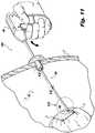
- Surgical fastener applier 1000may be inserted through an opening, e.g., an incision or naturally-occurring orifice, in a layer of tissue "T” and into a body cavity "BC" below.
- an openinge.g., an incision or naturally-occurring orifice
- surgical fastener applier 1000may be subject to a bending load, i.e., surgical fastener applier 1000 may bow, flex, or otherwise deflect in response to manipulation of surgical fastener 1000 by an operator during the course of a minimally invasive procedure.
- surgical fastener applier 2000may be subject to bending loads in the same manner as surgical fastener applier 1000 described above.
- the flexibility afforded to the drive portion 200' by the configuration of the coiled spring 230'is present along an axially longer section of drive portion 200' as opposed to drive portion 200.
- drive portion 200'includes an axially shorter region of increased flexibility afforded by the stiffener member 220' as compared to the drive portion 200.
- Coiled spring 230"is configured as a tubular spring, i.e., coiled spring 230' is wound in a manner such that the body 232" of coiled spring 230" defines a variable pitch along its axial length.
- Coiled spring 230"may be maintained in an axially compressed position, e.g., by welding successive coils to each other and/or to the inner surface of outer tube 210, or by plastic deformation of portions of coiled spring 230" along proximal portions of the coiled spring 230, i.e., coiled spring 230" defines a smaller pitch along proximal portions of coiled spring 230" and a gradually larger pitch along distal portions of coiled spring 230". Accordingly, coiled spring 230" may define a proximal compressed region "PR", an intermediate transition region "TR” and a distal non-compressed region "NR.”
Landscapes
- Health & Medical Sciences (AREA)
- Life Sciences & Earth Sciences (AREA)
- Surgery (AREA)
- Heart & Thoracic Surgery (AREA)
- Engineering & Computer Science (AREA)
- Biomedical Technology (AREA)
- Nuclear Medicine, Radiotherapy & Molecular Imaging (AREA)
- Medical Informatics (AREA)
- Molecular Biology (AREA)
- Animal Behavior & Ethology (AREA)
- General Health & Medical Sciences (AREA)
- Public Health (AREA)
- Veterinary Medicine (AREA)
- Surgical Instruments (AREA)
Description
- This application claims the benefit of and priority to
U.S. Provisional Patent Application No. 61/776,811, filed March 12, 2013 - The present disclosure relates generally to surgical fastener appliers, and more particularly, a surgical fastener applier configured for continued operation in the presence of a bending load applied to an endoscopic portion thereof.
- Various surgical procedures require instruments capable of applying fasteners to tissue to form tissue connections or to secure objects to tissue. For example, during hernia repair it is often desirable to fasten a mesh to body tissue. In certain hernias, such as direct or indirect inguinal hernias, a part of the intestine protrudes through a defect in the support abdominal wall to form a hernial sac. The defect may be repaired using an open surgery procedure in which a relatively large incision is made and the hernia is closed off outside the abdominal wall by suturing. The mesh is attached with sutures over the opening to provide reinforcement.
- Minimally invasive, e.g., endoscopic or laparoscopic, surgical procedures are currently available to repair a hernia. In laparoscopic procedures surgery is performed in the abdomen through a small incision while in endoscopic procedures, surgery is performed through narrow endoscopic tubes or cannulas inserted through small incisions in the body. Laparoscopic and endoscopic procedures generally utilize long and narrow instruments capable of reaching deep within the body and configured to seal with the incision or tube they are inserted through. Additionally, the instruments must be capable of being actuated remotely, that is, from outside the body.
- Currently, minimally invasive surgical techniques for hernia repair utilize surgical fasteners, e.g., surgical tacks, staples, and clips, to secure the mesh to the tissue to provide reinforcement to the repair and structure for encouraging tissue ingrowth. Surgical fasteners are often applied through an elongate instrument for delivery to the mesh, and are manipulated from outside a body cavity. Challenges are presented in the course of minimally invasive surgical procedures when an elongate instrument is flexed or deflected, e.g., when being manipulated by an operator, encountering an obstruction, or otherwise subject to a bending load. Accordingly, there is a need for an improved instrument configured to withstand a bending load for delivering surgical fasteners to a minimally invasive surgical procedure site.
EP1908409 discloses a coil fastener applier having a flexible elongated tubular portion. Coil fastener applier includes a housing, a flexible elongated tubular portion, a flexible drive member, a fastener assembly and a trigger. Housing defines a longitudinal axis and includes a stationary handle affixed thereto. Flexible elongated tubular portion extends distally from housing. Flexible drive member is rotatably mounted within flexible elongated tubular portion.DE102010015009 discloses a flexible shaft and means to adapt the stiffness of the shaft to provide bending and stiff regions of the shaft.- The present invention is defined by the features of the independent claim. Preferred embodiments are given in the dependent claims.
- A surgical fastener applier is disclosed and includes a handle portion, a tubular member extending from the handle portion and defining a longitudinal axis, a drive member rotatably supported in the tubular member and in the handle portion, and a plurality of fasteners. The drive member is configured to rotate while in a deflected condition with respect to the longitudinal axis. The plurality of fasteners is disposed within the tubular member and is configured to engage a portion of the drive member such that rotational motion of the drive member causes distal advancement of at least one fastener of the plurality of fasteners through the tubular member.
- According to one embodiment of the present disclosure, the drive member includes a proximal portion, a central portion, and a distal portion, the central portion having a flexible configuration. According to another embodiment, a distal portion of the drive member defines at least one tine to engage a portion of at least one fastener of the plurality of fasteners. In yet another embodiment, the drive member is configured for deflection relative to the longitudinal axis at a rate different than that of the tubular member.
- In one embodiment of the present disclosure, the surgical fastener applier further includes a drive gear operatively connecting the handle portion and the drive member. The drive gear may be configured to transmit rotational motion to the drive member upon actuation of the handle portion. In another embodiment the drive member includes a proximal portion, a central portion, and a distal portion, the central portion having a torsionally stiff configuration. In yet another embodiment, the drive member includes a proximal portion, a central portion, and a distal portion, the central portion configured for continued rotation in the presence of a bending load.
- In another embodiment of the present disclosure, the tubular member includes a coiled spring circumferentially disposed about a portion of the drive member. In one embodiment of the present disclosure, the coiled spring is configured to engage a portion of at least one of the plurality of fasteners.
- According to another embodiment of the present disclosure, a surgical fastener applier is disclosed, and includes a handle portion, a tubular member, a stiffener member, a coiled spring, a drive member, and a plurality of fasteners. The tubular member extends from the handle portion and defines a longitudinal axis. The stiffener member has a different rigidity than the tubular member. The coiled spring is disposed within the tubular member and is configured to maintain a substantially straight condition of the tubular member. The drive member is rotatably supported in the tubular member and in the handle portion, and includes a portion having a longitudinally flexible and torsionally stiff configuration. The plurality of fasteners is disposed within the tubular member and each fastener is configured to engage a portion of the drive member such that rotational motion of the drive member causes distal advancement of at least one fastener of the plurality of fasteners through the tubular member. At least one fastener of the plurality of fasteners is engaged with the coiled spring. A clearance is defined between the drive member and the tubular member, and the drive member is configured for rotation in a deflected condition.
- According to one embodiment, the coiled spring has a substantially constant pitch along the longitudinal axis. The coiled spring may have a variable pitch along the longitudinal axis. According to another embodiment, the coiled spring includes an axially compressed portion. The axially compressed portion of the coiled spring may be maintained via a welding to an inner surface of the tubular member. The axially compressed portion of the coiled spring may be configured to undergo deflection with respect to the longitudinal axis at different rate than the remainder of the coiled spring. According to yet another embodiment, the axially compressed portion of the coiled spring is located at a proximal portion of the coiled spring.
- Embodiments of the present disclosure will be appreciated by reference to the drawings, wherein:
FIG. 1 is a perspective view of a surgical fastener applier according to the present disclosure;FIG. 2 is a perspective view, with parts-separated, of the surgical fastener applier ofFIG. 1 ;FIG. 2a is an enlarged view of a pinion gear as highlighted in the area of detail identified inFIG. 2 ;FIG. 3 is a perspective view, with parts-separated, of a drive portion of the surgical fastener applier ofFIG. 1 ;FIG. 4 is an enlarged view of the area of detail identified inFIG. 3 ;FIG. 5 is a longitudinal cross-sectional view taken along the area of detail identified inFIG. 3 ;FIG. 6 is a longitudinal cross-sectional view taken along the area of detail identified inFIG. 3 ;FIG. 7 is a side elevational view, partially cut-away, of the surgical fastener applier ofFIG. 1 ;FIG. 8 is a transverse cross-sectional view taken along section line 8-8 ofFIG. 7 ;FIG. 9 is a longitudinal cross-sectional view taken along section line 9-9 ofFIG. 1 ;FIG. 10 is a cross-sectional view taken along section line 10-10 ofFIG. 1 ;FIG. 11 is a perspective view of the surgical fastener applier shown inserted through a body wall, shown in cut-away;FIG. 12 is a cross-sectional view taken along section line 12-12 ofFIG. 11 ;FIG. 13 is a cut-away view of the area of detail identified inFIG. 11 ;FIG. 14 is a perspective view of an alternative embodiment of a surgical fastener applier according to the present disclosure;FIG. 15 is a cross-sectional view taken along section line 15-15 ofFIG. 14 ;FIG. 16 is a perspective view, with parts-separated, of the surgical fastener applier shown inFIG. 14 ;FIG. 17 is an enlarged cross-sectional view of the area of detail identified inFIG. 16 ;FIG. 18 is a cross-sectional view taken along section line 18-18 ofFIG. 14 ;FIG. 19 is a perspective view of an alternative embodiment of a surgical fastener applier according to the present disclosure;FIG. 20 is a cross-sectional view taken along section line 20-20 ofFIG. 19 ;FIG. 21 is a perspective view, with parts-separated, of the surgical fastener applier shown inFIG. 19 ;FIG. 22 is an enlarged cross-sectional view of the area of detail identified inFIG. 21 ; andFIG. 23 is a cross-sectional view taken along section line 23-23 ofFIG. 19 .- With reference now to the drawings wherein like numerals represent like elements throughout the several views, the presently-disclosed surgical fastener applier will be described. As used herein, the term "operator" may refer to any user, e.g., a nurse, doctor, or clinician, of the presently-disclosed surgical fastener applier. Further, the term "distal" refers to that portion of the applier, or component thereof, further from the operator while the term "proximal" refers to that portion of the surgical fastener applier, or component thereof, closer to the operator.
- Referring initially to
FIG. 1 , asurgical fastener applier 1000 is shown.Surgical fastener applier 1000 includes a handle portion orassembly 100 and a drive portion orassembly 200 extending away from thehandle portion 100.Handle portion 100, as shown, may have a manual, pistol-type ergonomic grip configuration suitable for grasping by an operator.Drive portion 200, as shown, has an elongate tubular configuration and is sized for endoscopic insertion into a body cavity. - Turning to
FIG. 2 , handleportion 100 ofsurgical fastener applier 1000 includes a pair of housing half-sections drive gear 120, and atrigger 130.Handle portion 100 is connected to thedrive portion 200 of thesurgical fastener applier 1000 via acollar 140, as will be described further below. - Housing half-
sections drive gear 120 is disposed within housing half-sections Drive gear 120 includes apinion gear 122 and abevel gear 124.Drive gear 120 operates in coordination withtrigger 130 and atrigger spring 132, as will be described further below. - Referring additionally to
FIG. 2a ,pinion gear 122 includes ahub 122a having a circular configuration and defining a series of radially outward ridges orteeth 122b. Anarm 122c extends radially away from thehub 122a.Arm 122c has a flat, tapered configuration, and tangentially intersects a flat side of thehub 122a.Arm 122c includes acam 122d having a sloped configuration and protruding from a major surface of thearm 122c and away from thehub 122a. Bevel gear 124 has a circular, disc-shaped configuration and defines a series of circumferentially-disposed ridges orteeth 124a extending from a major surface thereof.Bevel gear 124 also includes anarcuate slot 124b formed radially inward on the major surface of thebevel gear 124 with respect to theteeth 122b ofpinion gear 122, and is configured to receivecam 122d of thepinion gear 122, as will be described further below.Trigger 130, as shown, includes abody 130a which defines anengagement surface 130b configured for manual engagement by, e.g., the fingers of an operator. With additional reference toFIG. 7 ,trigger 130 includes an arcuate proximal surface 130c including a series ofteeth 130d.Teeth 130d oftrigger 130 are configured to interengageteeth 122b ofpinion gear 122, as will be described further below.Trigger spring 132, as shown, may be configured as a torsional spring, and is operably coupled with thetrigger 130, as will be described further below.- Turning now to
FIG. 3 , the components of thedrive potion 200 will be described in detail.Drive portion 200 includes an outertubular member 210, astiffener member 220, acoiled spring 230 and adrive member 240.Drive portion 200 is configured and dimensioned to accommodate a series ofsurgical fasteners 300, as will be described further below. - Outer
tubular member 210 ofdrive portion 200 is an elongate, tubular member defining a longitudinal axis "A" and having aproximal portion 212 and adistal portion 214, and defining an interior channel orlumen 216 within which other portions of thedrive portion 200 are disposed, as will be described further below.Tubular member 210 may be formed of any suitable biocompatible material, e.g., stainless steel. Stiffener member 220 is an elongate tubular member dimensioned to fit within theinterior lumen 216 of and along theproximal portion 212 of outertubular member 210.Stiffener member 220 is formed of a material having a different, e.g., higher, rigidity than thecoiled spring 230, as will be described further below.Coiled spring 230 also has a different rigidity than the outertubular member 210.Spring 230 may be made of a stainless steel, such as type 302 stainless steel.Coiled spring 230 is configured as a tubular spring, i.e., coiledspring 230 is wound in a manner such that thebody 232 of coiledspring 230 has a diameter "D" and defines a pitch "P" (FIG. 9 ). Accordingly, the spacing between successive winds or coils of thebody 232 of thecoiled spring 230 define a substantially spiraled path within which asurgical fastener 300 is configured to rotate and travel, as will be described further below. Owing to the resilient, i.e., elastic, configuration of coiledspring 230, coiledspring 230 has a different rigidity thanstiffener member 200 described above, i.e., coiledspring 230 is more flexible thanstiffener member 220. Accordingly,stiffener member 220 may be formed of a material with a relatively higher rigidity thancoiled spring 230.Stiffener member 220 may be formed of, e.g., a polymeric or metallic material.Drive member 240 includes aproximal portion 242, acentral portion 244, and adistal driving portion 246.Drive member 240 has a generally tubular configuration, and is dimensioned to extend withinstiffener member 220 and coiledspring 230, and within theinterior channel 216 of the outertubular member 210.Drive member 240 may have any suitable longitudinally flexible, torsionally stiff configuration, e.g., a flexible cable. It is contemplated that each ofproximal portion 242 anddistal driving portion 246 ofdrive member 240 have a relatively more rigid or stiff configuration as compared tocentral portion 244 ofdrive member 240, i.e.,central portion 244 ofdrive member 240 defines a relatively more flexible region ofdrive member 240 as compared toproximal portion 242 anddistal driving portion 246 ofdrive member 240. In this manner,central portion 244 ofdrive member 240 has different mechanical properties relative to the remainder ofdrive member 240. For example, the central portion may be formed of a multi-strand twisted cable, a braided cable or a tube. The tube may be laser cut in patterns to increase flexibility.Proximal portion 242 of thedrive member 240 is configured to be fit within acollar 140, as shown.Collar 140 includes atubular body 140a having a proximal beveled portion 140b.Drive member 240 is attached to handle portion 100 (FIG. 1 ) viacollar 140, and may be secured with fasteners 142, which may be, e.g., pins, screws, or bolts. Alternatively, theproximal portion 242 ofdrive member 240 may be integrally formed, e.g., welded, brazed, or adhered withcollar 140. In some embodiments,drive member 240 may be press-fit intocollar 140.Central portion 244 ofdrive member 240 is a substantially cylindrical portion that torsionally stiff, yet capable of bending along the longitudinal axis A, i.e.,central portion 244 ofdrive member 240 is configured to bend along the longitudinal axis A while maintaining a substantially constant radial configuration. It is contemplated thatcentral portion 244 ofdrive member 240 continues to rotate, in the presence of external forces. Accordingly,central portion 244 may be formed of a flexible, yet high-strength material, e.g., stainless steel configured as previously described.- Distal driving
portion 246 ofdrive member 240 has a forked or splined configuration, i.e.,distal driving portion 246 defines a pair oftines 246a circumferentially spaced by a pair of respectiveradial gaps 246b.Tines 246a are configured to engage a portion ofsurgical fasteners 300 to transmit rotational forces tosurgical fasteners 300, as will be described further below. - Referring additionally to
FIG. 4 ,surgical fasteners 300 will now be described in detail.Surgical fasteners 300, as shown, are configured to be disposed within theinterior channel 216 of outertubular member 210.Surgical fasteners 300 may be loaded into outertubular member 210 in an axially stacked column. Eachsurgical fastener 300 includes ahead section 310, amesh retention section 320, and a tissue-snaringsection 322.Head section 310 includes a pair of opposing threadedsections respective tine 246a of thedistal driving portion 246 of drive member 240 (FIG. 3 ), as will be described further below.Mesh retention section 320 ofsurgical fastener 300 functions to lock, anchor, or otherwise retain a surgical mesh "M" (FIG. 11 ) ontosurgical fastener 300 whensurgical fastener 300 is advanced into mesh M, as will be described further below. An exemplary surgical fastener is disclosed inU.S. Patent Application Publication No. 2011/0282401 to Corradi, et al. - Turning now to
FIGS. 5- 10 ,surgical fastener applier 1000 is shown with the above-described components assembled. Housing half-sections handle portion 100 are coupled in any conventional manner, e.g., snap-fit or ultrasonic welding. Outertubular member 210 may be e.g., clamped or welded withhandle portion 100.Collar 140 is rotatably disposed within a distal portion of thehandle portion 100.Collar 140 may be held in place by a portion of housing half-sections - With additional reference to
FIG. 3 , the assembled housing half-sections gear 120 is disposed.Pinion gear 122 andbevel gear 124 are rotatably mounted, e.g., supported by a pin, axel, or dowel (not shown) within the housing half-sections pinion gear 122 andbevel gear 124 are laterally adjacent and disposed in concentric relation. In this manner,drive gear 120 is arranged such that thecam 122d protruding from thearm 122c of the pinion gear is aligned to enter thearcuate slot 124b ofbevel gear 124 to rotate thebevel gear 124. - The proximal beveled end 140b of the
collar 140 is disposed such that the teeth 124c of thebevel gear 124 are held in interengaging relation with the proximal beveled end 140b of thecollar 140.Trigger 130 is mounted distally below thedrive gear 120 such that theteeth 130d on the proximal surface 130c oftrigger 130 are disposed to interengage theteeth 122b ofpinion gear 122.Trigger spring 132 is disposed within thehandle portion 100 proximally of thetrigger 130 to bias thetrigger 130 in a distal direction and to provide a counterforce to manual squeezing of thetrigger 130.Trigger spring 132 may be configured to provide a predetermined resistance to compression, e.g., to increase tactile feedback to an operator or to minimize slipping of the manual engagement ofhandle portion 100 by an operator. - As described above, the
drive portion 200 extends distally away from thehandle portion 100. The outertubular member 210 of the drive portion is mounted in a rotationally fixed manner with respect to thehandle portion 100. Thestiffener member 220 is concentrically disposed within the outertubular member 210 along aproximal portion 212 of the outertubular member 210.Stiffener member 220 is rotationally fixed with respect to the outertubular member 210, and may be secured to an inner surface of the outertubular member 210 in any conventional manner, e.g., adhesion, welding, or press-fit. Coiled spring 230, as shown, is concentrically disposed within the outertubular member 210 along adistal portion 214 of the outertubular member 210.Coiled spring 230 is also rotationally fixed with respect to the outertubular member 210 and may be secured to an inner surface of the outer tubular member in any conventional manner, e.g., adhesion, welding, brazing, or press-fit.Stiffener member 220 and coiledspring 230 may be disposed in a longitudinally adjacent, e.g., axially abutting relation within theinterior channel 216 of outertubular member 210, or a gap may be defined between adjoining ends of thestiffener member 220 and coiledspring 230.Drive member 240, as shown, is concentrically disposed within both thestiffener member 220 and coiledspring 230, and extends substantially the length of the outertubular member 210. Theproximal portion 242 ofdrive member 240 is secured within the distal portion 144 ofcollar 140 via pins 142. In this manner,drive member 240 is free to rotate within respect to the outertubular member 210.- Turning momentarily to
FIGS. 9 and 10 , thesurgical fasteners 300 are disposed within thecoiled spring 230 such that thetines 246a of thedistal driving portion 240 extend axially through the slotted sections 316a, 316b of thehead section 310. Accordingly, the opposingthread sections surgical fasteners 300 are disposed between theradial gaps 246b (FIG. 3 ) defined by thetines 246a such that, upon rotation of thedrive member 240, thetines 246b are disposed to exert a torque on thehead section 310 of thesurgical fasteners 300. As described above, the opposingthread sections surgical fasteners 300 are disposed within the helical path defined by the spaces between successive winds or coils of thecoiled spring 230. As will be described further below, the inter-engagement of thehead section 310 of thesurgical fasteners 300, in particular, the opposingthread sections coiled spring 230 provides a guided, helical path along which thesurgical fasteners 300 advance upon rotation. - With additional reference now to
FIG. 11 , the operation of thesurgical fastener applier 1000 will be described in detail.Surgical fastener applier 1000 may be inserted through an opening, e.g., an incision or naturally-occurring orifice, in a layer of tissue "T" and into a body cavity "BC" below.Surgical fastener applier 1000 may be inserted through a surgical access port, as shown, to minimize trauma to the surrounding layer of tissue "T." Upon actuation of thetrigger 130, i.e., the concentric movement oftrigger 130 with respect to housing half-sections teeth 130d on the proximal portion of thetrigger 130 interengages the radiallyoutward teeth 122b of thepinion gear 122 to cause rotation of thepinion gear 122 within the interior chamber of defined by thehandle portion 100. As thearm 122c of thepinion gear 122 travels in a circular path with the rotation of thehub 122a ofpinion gear 122, thecam 122d extending from thearm 122c is brought into alignment with and enters thearcuate slot 124b of thebevel gear 124, causing rotation of thebevel gear 124. Due to the sloped configuration of thecam 122d, thecam 122d is configured to drive the bevel gear 24 in a first, forward rotational direction, and is configured to disengage, i.e., slip, from thearcuate slot 124b of thebevel gear 122d in a second, reverse rotational direction. Such a configuration provides an anti-reverse drive for thedrive gear 120, and is described in detail inU.S. Patent No. 8,114,099 to Shipp . - As the
bevel gear 124 rotates within the interior chamber defined by thehandle portion 100, theteeth 124a of thebevel gear 124 interengage the proximal beveled portion ofcollar 140. As thecollar 140 is secured to thedrive member 240 via pins 142, actuation of thehandle portion 100 of thesurgical fastener apparatus 1000 in the manner described above causes rotation of thedrive member 240. As thedrive member 240 rotates with thecollar 140, thetines 246a of thedistal driving portion 246 of thedrive member 240 cause rotation of thesurgical fasteners 300. As thehead portion 310, specifically, opposingthread sections surgical fastener 300 are engaged within the helical path defined by the spacing of successive winds or coils of coiledspring 230, rotation of eachsurgical fastener 300 causes distal advancement of each surgical fastener through thedrive portion 200 ofsurgical fastener applier 1000. As shown,surgical fastener applier 1000 may be placed above an internal body structure "S," e.g., an abdominal wall, and brought into close proximity with a mesh "M" such thatsurgical fastener applier 1000 is positioned to advance one or moresurgical fasteners 300 through mesh "M" and into the internal structure "S." - As shown,
surgical fastener applier 1000 may be subject to a bending load, i.e.,surgical fastener applier 1000 may bow, flex, or otherwise deflect in response to manipulation ofsurgical fastener 1000 by an operator during the course of a minimally invasive procedure. - Turning now to
FIGS. 12 and 13 , thecentral portion 244 ofdrive member 240 is shown disposed within theinterior channel 212 of thedrive portion 200 ofsurgical fastener applier 1000 such that a clearance "C" is defined between the outer surface of thedrive member 240 and the interior surface of thestiffener member 220 or coiledspring 230. Clearance "C" affords the drive member 240 a degree of movement within thedrive portion 100 ofsurgical fastener applier 1000 under a bending load. Owing to the flexible, yet torsionally stiff configuration of thecentral portion 244 ofdrive member 240,central portion 244 ofdrive member 240 facilitates continued freedom of rotation of thedrive member 240 under deflection. Thus, thecentral portion 244 ofdrive member 240 deflects under a bending load at a rate different than outertubular member 210. In this manner,surgical fastener applier 1000 is configured to operate to applysurgical fasteners 300 under a bending load that would have bound a surgical fastener applier devoid of a drive member having some flexible portion thereof. - Turning to
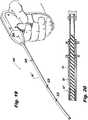
FIGS. 14-18 , an alternative configuration of a surgical fastener applier, generally designated 2000, will be described.Surgical fastener applier 2000 is substantially similar tosurgical fastener 1000 above, and will only be described to discuss the differences therein.Surgical fastener applier 2000 includes a drive portion 200' that includes outertubular member 210, a stiffener member 220', a coiled spring 230', and drivemember 240. - Stiffener member 220' is an elongate tubular member dimensioned to fit within the
interior channel 216 along theproximal portion 212 of outertubular member 210. Stiffener member 220' has a different axial length, i.e., stiffener member 220' is axially shorter thanstiffener member 220 described above. In accordance with the present disclosure and the present embodiment, it is contemplated that stiffener member 220' has an axial length of about 3,81cm (1.5 inches) Stiffener member 220' is formed of a material having a different, e.g., higher, rigidity than the coiled spring 230', as will be described further below. Accordingly, stiffener member 220' may be formed of a high-strength polymeric or metallic material, e.g., stainless steel. - Coiled spring 230' is configured as a tubular spring, i.e., coiled spring 230' is wound in a manner such that the body 232' of coiled spring 230' defines a pitch. Coiled spring 230' is disposed longitudinally adjacent the stiffener member 220' within the outer
tubular member 210. Owing to the axially shortened configuration of stiffener member 220' described above, coiled spring 230' has a different axial length, i.e., coiled spring 230' is axially longer thancoiled spring 230 described above. Coiled spring 230' defines a substantially spiraled path within which asurgical fastener 300 is configured to rotate in the manner described above with respect tosurgical fastener applier 1000. Owing to the resilient, i.e., elastic, configuration of coiled spring 230', coiled spring 230' has a different rigidity than stiffener member 220' described above, i.e., coiled spring 230' is more flexible than stiffener member 220'. - During use,
surgical fastener applier 2000 may be subject to bending loads in the same manner assurgical fastener applier 1000 described above. Owing to the different axial lengths of stiffener member 220' and coiled spring 230', the flexibility afforded to the drive portion 200' by the configuration of the coiled spring 230' is present along an axially longer section of drive portion 200' as opposed to driveportion 200. Correspondingly, drive portion 200' includes an axially shorter region of increased flexibility afforded by the stiffener member 220' as compared to thedrive portion 200. Such a flexibility profile may be desirable, e.g., in anticipation of increased bending loads or a bending profile including stress concentrations along locations of drive portion 200' ofsurgical fastener applier 2000 proximally located with respect to corresponding locations ofdrive portion 200 ofsurgical fastener applier 1000. - Turning to
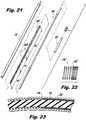
FIGS. 19-23 , an alternative configuration of a surgical fastener applier, generally designated 3000, will be described.Surgical fastener applier 3000 is substantially similar tosurgical fastener 1000 andsurgical fastener 2000 described above, and will only be described to discuss the differences therein.Surgical fastener applier 3000 includes adrive portion 200" and includes outertubular member 210, stiffener member 220', acoiled spring 230", and drivemember 240. Coiled spring 230" is configured as a tubular spring, i.e., coiled spring 230' is wound in a manner such that thebody 232" of coiledspring 230" defines a variable pitch along its axial length.Coiled spring 230" may be maintained in an axially compressed position, e.g., by welding successive coils to each other and/or to the inner surface ofouter tube 210, or by plastic deformation of portions of coiledspring 230" along proximal portions of thecoiled spring 230, i.e., coiledspring 230" defines a smaller pitch along proximal portions of coiledspring 230" and a gradually larger pitch along distal portions of coiledspring 230". Accordingly, coiledspring 230" may define a proximal compressed region "PR", an intermediate transition region "TR" and a distal non-compressed region "NR."- During use,
surgical fastener applier 3000 may be subject to bending loads in the same manner assurgical fastener appliers coiled spring 230", thedrive portion 200" of thesurgical fastener 3000 may define a variable bending profile along the section of thedrive portion 200" within which thecoiled spring 230" is disposed. In particular, the proximal compressed region "PR" of coiledspring 230" may deflect at a different rate than the intermediate transition region "TR" and distal non-compressed region "NR" of coiledspring 230". Such a flexibility profile may be desirable, e.g., in anticipation of variable or increased bending loads or a bending profile including increased stress concentrations in the proximal direction ofdrive portion 200" as compared to driveportion 200. - It will be understood that various modifications may be made to the embodiments disclosed herein. Therefore, the above description should not be construed as limiting, but merely as exemplifications of preferred embodiments. Those skilled in the art will envision other modifications within the scope of the claims appended thereto.
Claims (11)
- A surgical fastener applier (1000, 2000, 3000), comprising:a handle portion (100);a tubular member (210) extending from the handle portion and defining a longitudinal axis;a stiffener member (220) provided within the tubular member, the stiffener member having a different rigidity than the tubular member;a coiled spring (230) disposed within the tubular member and being configured to maintain a substantially straight condition of the tubular member;a drive member (240) including a central portion (244) being radially flexible and torsionally stiff and a relatively stiff distal driving portion (246) as compared to central portion (244), the drive member extending within the stiffener member and within the coiled spring and rotatably supported in the tubular member and in the handle portion; anda plurality of fasteners (300) disposed within the tubular member and each fastener being configured to engage a portion of the drive member such that rotational motion of the drive member causes distal advancement of at least one fastener of the plurality of fasteners through the tubular member, at least one fastener of the plurality of fasteners engaged with the coiled spring;wherein a clearance is defined between the drive member and the stiffener member, and the drive member is configured for rotation in a deflected condition.
- The surgical fastener applier (1000, 2000, 3000) of claim 1, wherein the coiled spring (230) has a substantially constant pitch along the longitudinal axis.
- The surgical fastener applier (1000, 2000, 3000) of claim 1, wherein the coiled spring (230) has a variable pitch along the longitudinal axis.
- The surgical fastener applier (1000, 2000, 3000) of any preceding claim, wherein the coiled spring (230) includes an axially compressed portion.
- The surgical fastener applier (1000, 2000, 3000) of claim 4, wherein the axially compressed portion of the coiled spring (230) is maintained via a welding to an inner surface of the tubular member (210).
- The surgical fastener applier (1000, 2000, 3000) of claim 4 or claim 5, wherein the axially compressed portion of the coiled spring (230) is configured to undergo deflection with respect to the longitudinal axis at different rate than the remainder of the coiled spring.
- The surgical fastener applier (1000, 2000, 3000) of any of claims 1 to 4, wherein the axially compressed portion of the coiled spring (230) is located at a proximal portion of the coiled spring.
- The surgical fastener applier (1000, 2000, 3000) of any preceding claim, wherein the distal driving portion (246) of the drive member (240) defines at least one tine (246a) to engage a portion of at least one fastener of the plurality of fasteners (300).
- The surgical fastener applier (1000, 2000, 3000) of any preceding claim, wherein the drive member (240) is configured for deflection relative to the longitudinal axis at a rate different than that of the tubular member (210).
- The surgical fastener applier (1000, 2000, 3000) of any preceding claim, further comprising a drive gear (120) operatively connecting the handle portion (100) and the drive member (240).
- The surgical fastener applier (1000, 2000, 3000) of claim 10, wherein the drive gear (120) is configured to transmit rotational motion to the drive member (240) upon actuation of the handle portion (100).
Applications Claiming Priority (2)
| Application Number | Priority Date | Filing Date | Title |
|---|---|---|---|
| US201361776811P | 2013-03-12 | 2013-03-12 | |
| US14/199,096US9358010B2 (en) | 2013-03-12 | 2014-03-06 | Flex cable and spring-loaded tube for tacking device |
Publications (2)
| Publication Number | Publication Date |
|---|---|
| EP2777516A1 EP2777516A1 (en) | 2014-09-17 |
| EP2777516B1true EP2777516B1 (en) | 2019-05-15 |
Family
ID=50239520
Family Applications (1)
| Application Number | Title | Priority Date | Filing Date |
|---|---|---|---|
| EP14158946.5AActiveEP2777516B1 (en) | 2013-03-12 | 2014-03-11 | Flex cable and spring-loaded tube for tacking device |
Country Status (6)
| Country | Link |
|---|---|
| US (2) | US9358010B2 (en) |
| EP (1) | EP2777516B1 (en) |
| JP (2) | JP2014176648A (en) |
| CN (1) | CN104042266B (en) |
| AU (1) | AU2014201338B2 (en) |
| CA (1) | CA2845427A1 (en) |
Families Citing this family (29)
| Publication number | Priority date | Publication date | Assignee | Title |
|---|---|---|---|---|
| ES2279156T3 (en) | 2002-06-11 | 2007-08-16 | Tyco Healthcare Group Lp | MALE TIGHTS FOR HERNIAS. |
| US8926637B2 (en) | 2003-06-13 | 2015-01-06 | Covidien Lp | Multiple member interconnect for surgical instrument and absorbable screw fastener |
| US7670362B2 (en) | 2003-06-13 | 2010-03-02 | Tyco Healthcare Group Lp | Multiple member interconnect for surgical instrument and absorbable screw fastener |
| US10478179B2 (en) | 2004-04-27 | 2019-11-19 | Covidien Lp | Absorbable fastener for hernia mesh fixation |
| US9888920B2 (en)* | 2010-09-21 | 2018-02-13 | Sportwelding Gmbh | Connecting a plurality of tissue parts |
| US9351733B2 (en) | 2013-01-18 | 2016-05-31 | Covidien Lp | Surgical fastener applier |
| US9358010B2 (en)* | 2013-03-12 | 2016-06-07 | Covidien Lp | Flex cable and spring-loaded tube for tacking device |
| US9867620B2 (en) | 2013-03-14 | 2018-01-16 | Covidien Lp | Articulation joint for apparatus for endoscopic procedures |
| US9655621B2 (en) | 2013-03-15 | 2017-05-23 | Covidien Lp | Surgical instrument for dispensing tacks and solution |
| US10085746B2 (en) | 2013-06-28 | 2018-10-02 | Covidien Lp | Surgical instrument including rotating end effector and rotation-limiting structure |
| US9358004B2 (en) | 2013-06-28 | 2016-06-07 | Covidien Lp | Articulating apparatus for endoscopic procedures |
| US9668730B2 (en) | 2013-06-28 | 2017-06-06 | Covidien Lp | Articulating apparatus for endoscopic procedures with timing system |
| US9351728B2 (en) | 2013-06-28 | 2016-05-31 | Covidien Lp | Articulating apparatus for endoscopic procedures |
| US20150032130A1 (en) | 2013-07-24 | 2015-01-29 | Covidien Lp | Expanding absorbable tack |
| US9526498B2 (en) | 2013-09-17 | 2016-12-27 | Covidien Lp | Surgical device with a trigger lockout mechanism device |
| US10335146B2 (en)* | 2014-04-02 | 2019-07-02 | Coviden Lp | Surgical fastener applying apparatus, kits and methods for endoscopic procedures |
| US11090097B2 (en) | 2015-03-17 | 2021-08-17 | Covidien Lp | Connecting end effectors to surgical devices |
| US10363039B2 (en)* | 2015-11-20 | 2019-07-30 | Covidien Lp | Surgical fastener appliers |
| US10617409B2 (en) | 2016-10-21 | 2020-04-14 | Covidien Lp | Surgical end effectors |
| US10743859B2 (en) | 2016-10-21 | 2020-08-18 | Covidien Lp | Surgical end effectors |
| US11298123B2 (en) | 2016-10-21 | 2022-04-12 | Covidien Lp | Surgical end effectors |
| US10888309B2 (en) | 2017-01-31 | 2021-01-12 | Covidien Lp | Surgical fastener devices with geometric tubes |
| US11298126B2 (en) | 2018-05-02 | 2022-04-12 | Covidien Lp | Shipping wedge for end effector installation onto surgical devices |
| US11116500B2 (en) | 2018-06-28 | 2021-09-14 | Covidien Lp | Surgical fastener applying device, kits and methods for endoscopic procedures |
| DE102019115004A1 (en) | 2019-06-04 | 2020-12-10 | avateramedical GmBH | Surgical instrument for minimally invasive surgery |
| US11523817B2 (en) | 2019-06-27 | 2022-12-13 | Covidien Lp | Endoluminal pursestring device |
| USD944984S1 (en) | 2019-12-19 | 2022-03-01 | Covidien Lp | Tubular positioning guide |
| USD944985S1 (en) | 2019-12-19 | 2022-03-01 | Covidien Lp | Positioning guide cuff |
| US11197675B2 (en) | 2019-12-19 | 2021-12-14 | Covidien Lp | Positioning guide for surgical instruments and surgical instrument systems |
Family Cites Families (194)
| Publication number | Priority date | Publication date | Assignee | Title |
|---|---|---|---|---|
| US3866510A (en) | 1967-06-05 | 1975-02-18 | Carl B H Eibes | Self-tapping threaded bushings |
| DE1816949B1 (en) | 1968-12-24 | 1970-05-27 | Piv Antrieb Reimers Kg Werner | Conical pulley belt drive |
| DE2910546C3 (en) | 1979-03-17 | 1982-05-27 | P.I.V. Antrieb Werner Reimers GmbH & Co KG, 6380 Bad Homburg | Conical pulley belt drive |
| US4884572A (en) | 1986-05-20 | 1989-12-05 | Concept, Inc. | Tack and applicator for treating torn bodily material in vivo |
| CH681273A5 (en) | 1988-12-16 | 1993-02-26 | Sulzer Ag | |
| US5382254A (en) | 1989-07-18 | 1995-01-17 | United States Surgical Corporation | Actuating handle for surgical instruments |
| US5129906A (en) | 1989-09-08 | 1992-07-14 | Linvatec Corporation | Bioabsorbable tack for joining bodily tissue and in vivo method and apparatus for deploying same |
| US5236563A (en) | 1990-06-18 | 1993-08-17 | Advanced Surface Technology Inc. | Surface-modified bioabsorbables |
| US5085661A (en) | 1990-10-29 | 1992-02-04 | Gerald Moss | Surgical fastener implantation device |
| DE4108952A1 (en) | 1991-03-19 | 1992-09-24 | Beiersdorf Ag | DEVICE FOR SETTING WIND CLASPS |
| US5171249A (en) | 1991-04-04 | 1992-12-15 | Ethicon, Inc. | Endoscopic multiple ligating clip applier |
| US5171247A (en) | 1991-04-04 | 1992-12-15 | Ethicon, Inc. | Endoscopic multiple ligating clip applier with rotating shaft |
| US5207697A (en) | 1991-06-27 | 1993-05-04 | Stryker Corporation | Battery powered surgical handpiece |
| US5228256A (en) | 1991-10-02 | 1993-07-20 | Ross Dreveny | Anchor means and apparatus for installing same |
| US5312023A (en)* | 1991-10-18 | 1994-05-17 | United States Surgical Corporation | Self contained gas powered surgical apparatus |
| US5356064A (en) | 1991-10-18 | 1994-10-18 | United States Surgical Corporation | Apparatus and method for applying surgical staples to attach an object to body tissue |
| US5397046A (en) | 1991-10-18 | 1995-03-14 | United States Surgical Corporation | Lockout mechanism for surgical apparatus |
| US5433721A (en) | 1992-01-17 | 1995-07-18 | Ethicon, Inc. | Endoscopic instrument having a torsionally stiff drive shaft for applying fasteners to tissue |
| CA2088883A1 (en) | 1992-02-13 | 1993-08-14 | David T. Green | Endoscopic ligating instrument |
| US5246450A (en) | 1992-03-10 | 1993-09-21 | Edward Weck Incorporated | High capacity medical clip feeding and dispensing mechanism |
| US5342373A (en) | 1992-09-14 | 1994-08-30 | Ethicon, Inc. | Sterile clips and instrument for their placement |
| US5601224A (en) | 1992-10-09 | 1997-02-11 | Ethicon, Inc. | Surgical instrument |
| US5662662A (en) | 1992-10-09 | 1997-09-02 | Ethicon Endo-Surgery, Inc. | Surgical instrument and method |
| US5381943A (en) | 1992-10-09 | 1995-01-17 | Ethicon, Inc. | Endoscopic surgical stapling instrument with pivotable and rotatable staple cartridge |
| US5330487A (en) | 1992-12-17 | 1994-07-19 | Tfi Acquistion Corp. | Drive mechanism for surgical instruments |
| US5403327A (en) | 1992-12-31 | 1995-04-04 | Pilling Weck Incorporated | Surgical clip applier |
| US5398861A (en) | 1993-04-16 | 1995-03-21 | United States Surgical Corporation | Device for driving surgical fasteners |
| US5467911A (en) | 1993-04-27 | 1995-11-21 | Olympus Optical Co., Ltd. | Surgical device for stapling and fastening body tissues |
| DE69403271T2 (en) | 1993-04-27 | 1997-09-18 | American Cyanamid Co | Automatic laparoscopic applicator for ligation clips |
| US5439468A (en) | 1993-05-07 | 1995-08-08 | Ethicon Endo-Surgery | Surgical clip applier |
| US5522844A (en) | 1993-06-22 | 1996-06-04 | Johnson; Lanny L. | Suture anchor, suture anchor installation device and method for attaching a suture to a bone |
| US5344061A (en) | 1993-08-03 | 1994-09-06 | Lawrence Crainich | Ratchet assembly for medical instrument |
| KR100203955B1 (en) | 1993-08-03 | 1999-06-15 | 스피겔 알렌 제이 | Implant and ratcheting compression device |
| AU1011595A (en) | 1994-01-13 | 1995-07-20 | Ethicon Inc. | Spiral surgical tack |
| US5466243A (en) | 1994-02-17 | 1995-11-14 | Arthrex, Inc. | Method and apparatus for installing a suture anchor through a hollow cannulated grasper |
| US5681330A (en) | 1994-03-02 | 1997-10-28 | Ethicon Endo-Surgery, Inc. | Sterile occlusion fasteners and instrument and method for their placement |
| CA2143560C (en) | 1994-03-02 | 2007-01-16 | Mark Fogelberg | Sterile occlusion fasteners and instrument and method for their placement |
| US5474566A (en) | 1994-05-05 | 1995-12-12 | United States Surgical Corporation | Self-contained powered surgical apparatus |
| US5601571A (en) | 1994-05-17 | 1997-02-11 | Moss; Gerald | Surgical fastener implantation device |
| US5582616A (en) | 1994-08-05 | 1996-12-10 | Origin Medsystems, Inc. | Surgical helical fastener with applicator |
| EP0699418A1 (en) | 1994-08-05 | 1996-03-06 | United States Surgical Corporation | Self-contained powered surgical apparatus |
| US5562685A (en) | 1994-09-16 | 1996-10-08 | General Surgical Innovations, Inc. | Surgical instrument for placing suture or fasteners |
| US5730744A (en) | 1994-09-27 | 1998-03-24 | Justin; Daniel F. | Soft tissue screw, delivery device, and method |
| US5685474A (en) | 1994-10-04 | 1997-11-11 | United States Surgical Corporation | Tactile indicator for surgical instrument |
| DE19509966A1 (en) | 1995-03-18 | 1996-09-19 | Frank Ullrich Schuetz | Stapler and nail for surgery |
| US5553765A (en) | 1995-04-28 | 1996-09-10 | Ethicon Endo-Surgery, Inc. | Surgical stapler with improved operating lever mounting arrangement |
| US5626613A (en) | 1995-05-04 | 1997-05-06 | Arthrex, Inc. | Corkscrew suture anchor and driver |
| US5697935A (en) | 1995-09-12 | 1997-12-16 | Medex Marketing, Inc. | Device and method for removing fastening implements from bone |
| US5997552A (en) | 1995-10-20 | 1999-12-07 | United States Surgical Corporation | Meniscal fastener applying device |
| US5582615A (en) | 1995-10-30 | 1996-12-10 | Pilling Weck, Incorporated | Handle for surgical clip applicator systems |
| JPH09149906A (en) | 1995-11-29 | 1997-06-10 | Nagoya Rashi Seisakusho:Kk | Tool for curing bone disease |
| US5649931A (en) | 1996-01-16 | 1997-07-22 | Zimmer, Inc. | Orthopaedic apparatus for driving and/or removing a bone screw |
| US5762255A (en) | 1996-02-20 | 1998-06-09 | Richard-Allan Medical Industries, Inc. | Surgical instrument with improvement safety lockout mechanisms |
| US6099537A (en) | 1996-02-26 | 2000-08-08 | Olympus Optical Co., Ltd. | Medical treatment instrument |
| US5782844A (en) | 1996-03-05 | 1998-07-21 | Inbae Yoon | Suture spring device applicator |
| US5747953A (en) | 1996-03-29 | 1998-05-05 | Stryker Corporation | Cordless, battery operated surical tool |
| US5732806A (en) | 1996-03-29 | 1998-03-31 | Pilling Weck, Incorporated | Compensator to prevent backlash in a surgical instrument |
| EP0800796A1 (en) | 1996-04-12 | 1997-10-15 | Caron, Philippe | Screwdriving device incorporating a screw loader, particularly for use in maxillo-facial surgery |
| US7611521B2 (en) | 1996-09-13 | 2009-11-03 | Tendon Technology, Ltd. | Apparatus and methods for tendon or ligament repair |
| DE69736601T2 (en) | 1996-09-20 | 2007-12-27 | United States Surgical Corporation, Norwalk | Surgical device for attaching spiral clips |
| US5830221A (en) | 1996-09-20 | 1998-11-03 | United States Surgical Corporation | Coil fastener applier |
| CA2217435C (en) | 1996-10-04 | 2006-08-29 | United States Surgical Corporation | Tissue fastener implantation apparatus and method |
| US5928252A (en) | 1997-01-21 | 1999-07-27 | Regen Biologics, Inc. | Device and method for driving a needle and meniscal repair |
| US5843087A (en) | 1997-01-30 | 1998-12-01 | Ethicon, Inc. | Suture anchor installation tool |
| US5897564A (en) | 1997-04-08 | 1999-04-27 | Ethicon Endo-Surgery, Inc. | Endoscopic instrument assembly for fastening tissue |
| US5910105A (en) | 1997-04-14 | 1999-06-08 | C.R. Bard, Inc. | Control handle for an endoscope |
| US5941439A (en)* | 1997-05-14 | 1999-08-24 | Mitek Surgical Products, Inc. | Applicator and method for deploying a surgical fastener in tissue |
| US5957924A (en) | 1997-05-22 | 1999-09-28 | Bionx Implants Oy | Installation tool for suture anchor |
| US6010513A (en) | 1997-11-26 | 2000-01-04 | Bionx Implants Oy | Device for installing a tissue fastener |
| US6457625B1 (en) | 1998-02-17 | 2002-10-01 | Bionx Implants, Oy | Device for installing a tissue fastener |
| US5961524A (en) | 1998-03-11 | 1999-10-05 | Stryker Technologies Corporation | Screw and method of attachment to a substrate |
| US8075570B2 (en) | 2001-11-28 | 2011-12-13 | Aptus Endosystems, Inc. | Intraluminal prosthesis attachment systems and methods |
| US7491232B2 (en) | 1998-09-18 | 2009-02-17 | Aptus Endosystems, Inc. | Catheter-based fastener implantation apparatus and methods with implantation force resolution |
| US7591842B2 (en) | 1998-03-13 | 2009-09-22 | Aptus Endosystems, Inc. | Endovascular prosthesis with suture holder |
| US5931844A (en) | 1998-03-31 | 1999-08-03 | Smith & Nephew, Inc. | Surgical drive tool |
| US5976160A (en) | 1998-03-31 | 1999-11-02 | Design Standards Corporation | Handle mechanism with two distinct pivot points |
| WO1999058074A2 (en) | 1998-05-12 | 1999-11-18 | Scimed Life Systems, Inc. | Manual bone anchor placement devices |
| US6261302B1 (en) | 1998-06-26 | 2001-07-17 | Ethicon Endo-Surgery, Inc. | Applier for implantable surgical marker |
| US6228098B1 (en) | 1998-07-10 | 2001-05-08 | General Surgical Innovations, Inc. | Apparatus and method for surgical fastening |
| US6039753A (en) | 1998-07-16 | 2000-03-21 | Meislin; Robert | Single unit surgical fastener and method |
| US5911722A (en) | 1998-07-23 | 1999-06-15 | Millenium Devices Llc | Leban/Gordon surgical hand driver |
| US6146387A (en) | 1998-08-26 | 2000-11-14 | Linvatec Corporation | Cannulated tissue anchor system |
| WO2000016701A1 (en) | 1998-09-18 | 2000-03-30 | United States Surgical Corporation | Endovascular fastener applicator |
| US6235058B1 (en) | 1998-10-19 | 2001-05-22 | Douglas B. Huene | Bone plug anchoring device and methods for anchoring one or more tendons or other grafts using the bone plug anchoring device |
| US6887244B1 (en) | 1998-12-16 | 2005-05-03 | Medtronic, Inc. | Cordless surgical handpiece with disposable battery; and method |
| US6126670A (en) | 1998-12-16 | 2000-10-03 | Medtronic, Inc. | Cordless surgical handpiece with disposable battery; and method |
| CA2358387C (en) | 1998-12-31 | 2007-11-13 | Jeffrey E. Yeung | Tissue fastening devices and delivery means |
| US6387113B1 (en) | 1999-02-02 | 2002-05-14 | Biomet, Inc. | Method and apparatus for repairing a torn meniscus |
| US6074395A (en) | 1999-02-02 | 2000-06-13 | Linvatec Corporation | Cannulated tissue anchor insertion system |
| US6402757B1 (en) | 1999-03-12 | 2002-06-11 | Biomet, Inc. | Cannulated fastener system for repair of bone fracture |
| FR2795301B1 (en) | 1999-06-25 | 2001-08-31 | Prec | ENDOSCOPIC SURGERY INSTRUMENT |
| US6132435A (en) | 1999-09-14 | 2000-10-17 | Synthes (Usa) | Torque limiting device for surgical use |
| DE59901090D1 (en) | 1999-12-23 | 2002-05-02 | Storz Karl Gmbh & Co Kg | Decentralized drive screw |
| US6942674B2 (en) | 2000-01-05 | 2005-09-13 | Integrated Vascular Systems, Inc. | Apparatus and methods for delivering a closure device |
| US6440136B1 (en) | 2000-05-24 | 2002-08-27 | Medtronic Ps Medical, Inc. | Apparatus for attaching to bone |
| US7204847B1 (en) | 2000-07-28 | 2007-04-17 | C. R. Bard, Inc. | Implant anchor systems |
| US6632228B2 (en) | 2000-08-23 | 2003-10-14 | Scimed Life System, Inc. | System, method, and apparatus for accurately deploying particular medical appliances at a target site |
| CA2441883A1 (en) | 2000-09-01 | 2002-03-07 | Onux Medical, Inc. | Multi-fastener surgical apparatus and method |
| WO2002024081A1 (en) | 2000-09-22 | 2002-03-28 | Codman & Shurtleff, Inc. | Self centering bone drill |
| US6572626B1 (en) | 2000-10-19 | 2003-06-03 | Ethicon Endo-Surgery, Inc. | Surgical instrument having a fastener delivery mechanism |
| US6773438B1 (en) | 2000-10-19 | 2004-08-10 | Ethicon Endo-Surgery | Surgical instrument having a rotary lockout mechanism |
| US6551333B2 (en) | 2000-10-19 | 2003-04-22 | Ethicon Endo-Surgery, Inc. | Method for attaching hernia mesh |
| US6425900B1 (en) | 2000-10-19 | 2002-07-30 | Ethicon Endo-Surgery | Method for attaching hernia mesh |
| CA2692564C (en) | 2000-10-23 | 2013-08-27 | Tyco Healthcare Group Lp | Absorbable fastener and applying apparatus |
| US6733506B1 (en) | 2000-11-16 | 2004-05-11 | Ethicon, Inc. | Apparatus and method for attaching soft tissue to bone |
| US6439446B1 (en) | 2000-12-01 | 2002-08-27 | Stephen J. Perry | Safety lockout for actuator shaft |
| US6716226B2 (en) | 2001-06-25 | 2004-04-06 | Inscope Development, Llc | Surgical clip |
| US6695867B2 (en) | 2002-02-21 | 2004-02-24 | Integrated Vascular Systems, Inc. | Plunger apparatus and methods for delivering a closure device |
| US6663656B2 (en) | 2001-02-26 | 2003-12-16 | Arthrex, Inc. | Torque driver for interference screw |
| AU783705B2 (en) | 2001-07-02 | 2005-11-24 | Depuy France | Device for securing bits of bone together |
| AU2002348033B2 (en) | 2001-10-23 | 2008-05-29 | Covidien Lp | Surgical fasteners |
| US7128754B2 (en) | 2001-11-28 | 2006-10-31 | Aptus Endosystems, Inc. | Catheter-based fastener implantation apparatus and methods |
| US20050177180A1 (en) | 2001-11-28 | 2005-08-11 | Aptus Endosystems, Inc. | Devices, systems, and methods for supporting tissue and/or structures within a hollow body organ |
| AU2002353807B2 (en) | 2001-11-28 | 2008-08-14 | Aptus Endosystems, Inc. | Endovascular aneurysm repair system |
| US20090112303A1 (en)* | 2001-11-28 | 2009-04-30 | Lee Bolduc | Devices, systems, and methods for endovascular staple and/or prosthesis delivery and implantation |
| US8231639B2 (en) | 2001-11-28 | 2012-07-31 | Aptus Endosystems, Inc. | Systems and methods for attaching a prosthesis within a body lumen or hollow organ |
| US6929661B2 (en) | 2001-11-28 | 2005-08-16 | Aptus Endosystems, Inc. | Multi-lumen prosthesis systems and methods |
| US7147657B2 (en) | 2003-10-23 | 2006-12-12 | Aptus Endosystems, Inc. | Prosthesis delivery systems and methods |
| US7637932B2 (en) | 2001-11-28 | 2009-12-29 | Aptus Endosystems, Inc. | Devices, systems, and methods for prosthesis delivery and implantation |
| US7122028B2 (en) | 2001-12-19 | 2006-10-17 | Allegiance Corporation | Reconfiguration surgical apparatus |
| US6869435B2 (en) | 2002-01-17 | 2005-03-22 | Blake, Iii John W | Repeating multi-clip applier |
| ES2279156T3 (en) | 2002-06-11 | 2007-08-16 | Tyco Healthcare Group Lp | MALE TIGHTS FOR HERNIAS. |
| US6966919B2 (en) | 2002-09-20 | 2005-11-22 | Id, Llc | Instrument for applying a surgical fastener particularly for the transoral treatment of gastroesophageal reflux disease (GERD) |
| US7811312B2 (en) | 2002-12-04 | 2010-10-12 | Morphographics, Lc | Bone alignment implant and method of use |
| US6755836B1 (en) | 2002-12-20 | 2004-06-29 | High Plains Technology Group, Llc | Bone screw fastener and apparatus for inserting and removing same |
| DE10300787B4 (en) | 2003-01-13 | 2016-06-09 | A.M.I (Agency for Medical Innovations GmbH) | Device for attaching a mesh to human or animal tissue |
| US7070601B2 (en) | 2003-01-16 | 2006-07-04 | Triage Medical, Inc. | Locking plate for bone anchors |
| US7461574B2 (en) | 2003-04-28 | 2008-12-09 | Biomet Microfixation, Llc | Multiple screw delivery apparatus |
| US8926637B2 (en) | 2003-06-13 | 2015-01-06 | Covidien Lp | Multiple member interconnect for surgical instrument and absorbable screw fastener |
| US7670362B2 (en) | 2003-06-13 | 2010-03-02 | Tyco Healthcare Group Lp | Multiple member interconnect for surgical instrument and absorbable screw fastener |
| JP2007518446A (en) | 2003-07-11 | 2007-07-12 | エンドグン・メディカル・システムズ・リミテッド | Surgical fasteners and surgical fixation devices |
| US6905057B2 (en) | 2003-09-29 | 2005-06-14 | Ethicon Endo-Surgery, Inc. | Surgical stapling instrument incorporating a firing mechanism having a linked rack transmission |
| US7000819B2 (en) | 2003-09-29 | 2006-02-21 | Ethicon Endo-Surgery, Inc. | Surgical stapling instrument having multistroke firing incorporating a traction-biased ratcheting mechanism |
| US6988650B2 (en) | 2003-12-30 | 2006-01-24 | Ethicon Endo-Surgery, Inc. | Retaining pin lever advancement mechanism for a curved cutter stapler |
| US20060129152A1 (en) | 2004-12-10 | 2006-06-15 | Shipp John I | Absorbable Anchor for Hernia Mesh Fixation |
| US10478179B2 (en) | 2004-04-27 | 2019-11-19 | Covidien Lp | Absorbable fastener for hernia mesh fixation |
| US8114099B2 (en) | 2004-04-27 | 2012-02-14 | Tyco Healthcare Group Lp | Absorbable anchor for hernia mesh fixation |
| US7758612B2 (en) | 2004-04-27 | 2010-07-20 | Tyco Healthcare Group Lp | Surgery delivery device and mesh anchor |
| US20090118776A1 (en) | 2004-09-24 | 2009-05-07 | Biomec, Inc. | Tissue anchors |
| EP2641548B1 (en) | 2004-10-08 | 2015-08-19 | Covidien LP | Endoscopic surgical clip applier |
| US7604659B2 (en) | 2004-11-09 | 2009-10-20 | Lee James M | Method and apparatus for repair of torn rotator cuff tendons |
| US8333776B2 (en) | 2005-05-20 | 2012-12-18 | Neotract, Inc. | Anchor delivery system |
| US8216254B2 (en) | 2005-05-20 | 2012-07-10 | Neotract, Inc. | Anchor delivery system with replaceable cartridge |
| CN101466316B (en) | 2005-10-20 | 2012-06-27 | 阿普特斯内系统公司 | Devices systems and methods for prosthesis delivery and implantation including the use of a fastener tool |
| US20070162030A1 (en) | 2006-01-06 | 2007-07-12 | Ernest Aranyi | Multi-pronged compressive absorbable tack |
| US7862573B2 (en) | 2006-04-21 | 2011-01-04 | Darois Roger E | Method and apparatus for surgical fastening |
| WO2008010948A2 (en) | 2006-07-18 | 2008-01-24 | Davol Inc. | Method and apparatus for surgical fastening |
| US9017345B2 (en) | 2006-10-06 | 2015-04-28 | Covidien Lp | Coil fastener applier with flexible shaft |
| US9456877B2 (en) | 2006-12-01 | 2016-10-04 | Boston Scientific Scimed, Inc. | Direct drive instruments and methods of use |
| US8062306B2 (en) | 2006-12-14 | 2011-11-22 | Ethicon Endo-Surgery, Inc. | Manually articulating devices |
| WO2008112942A2 (en)* | 2007-03-13 | 2008-09-18 | Harris Peter S | Methods and devices for reducing gastric volume |
| US8377044B2 (en) | 2007-03-30 | 2013-02-19 | Ethicon Endo-Surgery, Inc. | Detachable end effectors |
| US7931660B2 (en) | 2007-05-10 | 2011-04-26 | Tyco Healthcare Group Lp | Powered tacker instrument |
| US7832408B2 (en) | 2007-06-04 | 2010-11-16 | Ethicon Endo-Surgery, Inc. | Surgical instrument having a directional switching mechanism |
| JP2008307383A (en) | 2007-06-12 | 2008-12-25 | Tyco Healthcare Group Lp | Surgical fastener |
| CN102793571B (en) | 2007-09-21 | 2014-12-17 | 柯惠Lp公司 | Surgical device |
| US20090112234A1 (en) | 2007-10-31 | 2009-04-30 | Lawrence Crainich | Reloadable laparoscopic fastener deploying device for use in a gastric volume reduction procedure |
| US8006365B2 (en) | 2008-01-30 | 2011-08-30 | Easylap Ltd. | Device and method for applying rotary tacks |
| US8087142B2 (en) | 2008-07-02 | 2012-01-03 | Easylap Ltd. | Pivoting tacker |
| US9386983B2 (en) | 2008-09-23 | 2016-07-12 | Ethicon Endo-Surgery, Llc | Robotically-controlled motorized surgical instrument |
| US20100270354A1 (en) | 2009-04-22 | 2010-10-28 | Ofir Rimer | Ergonomic rotary tacker |
| US8920439B2 (en) | 2009-05-12 | 2014-12-30 | Ethicon, Inc. | Applicator instruments having curved and articulating shafts for deploying surgical fasteners and methods therefor |
| US8579920B2 (en) | 2009-05-12 | 2013-11-12 | Ethicon, Inc. | Surgical fasteners, applicator instruments, and methods for deploying surgical fasteners |
| US8728098B2 (en) | 2009-05-12 | 2014-05-20 | Ethicon, Inc. | Surgical fasteners, applicator instruments, and methods for deploying surgical fasteners |
| US8894669B2 (en) | 2009-05-12 | 2014-11-25 | Ethicon, Inc. | Surgical fasteners, applicator instruments, and methods for deploying surgical fasteners |
| US8728099B2 (en) | 2009-05-12 | 2014-05-20 | Ethicon, Inc. | Surgical fasteners, applicator instruments, and methods for deploying surgical fasteners |
| US8821514B2 (en) | 2009-06-08 | 2014-09-02 | Covidien Lp | Powered tack applier |
| US8474679B2 (en) | 2009-07-13 | 2013-07-02 | C.R. Bard, Inc. | Instrument for applying a surgical fastener |
| US8672209B2 (en) | 2010-02-25 | 2014-03-18 | Design Standards Corporation | Laproscopic stapler |
| DE102010015009A1 (en) | 2010-04-14 | 2011-10-20 | Olympus Winter & Ibe Gmbh | Bend controllable tubular shaft for laparoscopic instrument, has outer tube formed as screw element that traverses bendable and rigid sections, where screw element is rigidly reinforced in rigid sections |
| US20110295282A1 (en) | 2010-05-26 | 2011-12-01 | Tyco Healthcare Group Lp | Fastener and drive method for soft tissue repair |
| US9028495B2 (en) | 2010-06-23 | 2015-05-12 | Covidien Lp | Surgical instrument with a separable coaxial joint |
| AU2012202677A1 (en)* | 2011-06-21 | 2013-01-17 | Ethicon Endo-Surgery, Inc. | A surgical fastener for applying a large staple through a small delivery port |
| FR2977471B1 (en) | 2011-07-07 | 2013-07-05 | Aspide Medical | DEVICE COMPRISING A PLURALITY OF IMPLANTS FOR FIXING PROTHETIC EQUIPMENT |
| CA2849887A1 (en) | 2011-09-26 | 2013-04-04 | Artack Medical (2013) Ltd. | Surgical fastening device and method |
| US9364231B2 (en) | 2011-10-27 | 2016-06-14 | Covidien Lp | System and method of using simulation reload to optimize staple formation |
| US8968311B2 (en) | 2012-05-01 | 2015-03-03 | Covidien Lp | Surgical instrument with stamped double-flag jaws and actuation mechanism |
| US9351733B2 (en) | 2013-01-18 | 2016-05-31 | Covidien Lp | Surgical fastener applier |
| US9358010B2 (en) | 2013-03-12 | 2016-06-07 | Covidien Lp | Flex cable and spring-loaded tube for tacking device |
| US9867620B2 (en) | 2013-03-14 | 2018-01-16 | Covidien Lp | Articulation joint for apparatus for endoscopic procedures |
| US9655621B2 (en) | 2013-03-15 | 2017-05-23 | Covidien Lp | Surgical instrument for dispensing tacks and solution |
| US9358004B2 (en) | 2013-06-28 | 2016-06-07 | Covidien Lp | Articulating apparatus for endoscopic procedures |
| US10085746B2 (en) | 2013-06-28 | 2018-10-02 | Covidien Lp | Surgical instrument including rotating end effector and rotation-limiting structure |
| US9668730B2 (en) | 2013-06-28 | 2017-06-06 | Covidien Lp | Articulating apparatus for endoscopic procedures with timing system |
| US9351728B2 (en) | 2013-06-28 | 2016-05-31 | Covidien Lp | Articulating apparatus for endoscopic procedures |
| US20150032130A1 (en) | 2013-07-24 | 2015-01-29 | Covidien Lp | Expanding absorbable tack |
| AU2014203843B2 (en) | 2013-08-23 | 2019-01-03 | Covidien Lp | Articulating apparatus for endoscopic procedures |
| US9526498B2 (en) | 2013-09-17 | 2016-12-27 | Covidien Lp | Surgical device with a trigger lockout mechanism device |
| US10368870B2 (en) | 2013-11-08 | 2019-08-06 | C.R. Bard, Inc. | Surgical fastener |
| US9445814B2 (en) | 2013-11-08 | 2016-09-20 | C.R. Bard, Inc. | Surgical fastener |
| US9615830B2 (en) | 2013-11-08 | 2017-04-11 | C.R. Bard, Inc. | Surgical fastener |
| US10335146B2 (en) | 2014-04-02 | 2019-07-02 | Coviden Lp | Surgical fastener applying apparatus, kits and methods for endoscopic procedures |
| US11090097B2 (en) | 2015-03-17 | 2021-08-17 | Covidien Lp | Connecting end effectors to surgical devices |
| US20180042591A1 (en) | 2016-08-15 | 2018-02-15 | Covidien Lp | Surgical instruments including adjustable handle assemblies |
- 2014
- 2014-03-06USUS14/199,096patent/US9358010B2/enactiveActive
- 2014-03-11CACA2845427Apatent/CA2845427A1/ennot_activeAbandoned
- 2014-03-11AUAU2014201338Apatent/AU2014201338B2/ennot_activeCeased
- 2014-03-11JPJP2014047708Apatent/JP2014176648A/enactivePending
- 2014-03-11EPEP14158946.5Apatent/EP2777516B1/enactiveActive
- 2014-03-12CNCN201410090675.XApatent/CN104042266B/enactiveActive
- 2016
- 2016-06-06USUS15/173,812patent/US10105135B2/enactiveActive
- 2018
- 2018-02-08JPJP2018020848Apatent/JP2018089404A/enactivePending
Non-Patent Citations (1)
| Title |
|---|
| None* |
Also Published As
| Publication number | Publication date |
|---|---|
| AU2014201338B2 (en) | 2018-01-04 |
| EP2777516A1 (en) | 2014-09-17 |
| CA2845427A1 (en) | 2014-09-12 |
| AU2014201338A1 (en) | 2014-10-02 |
| CN104042266B (en) | 2018-04-27 |
| JP2018089404A (en) | 2018-06-14 |
| US20140276969A1 (en) | 2014-09-18 |
| US10105135B2 (en) | 2018-10-23 |
| US9358010B2 (en) | 2016-06-07 |
| CN104042266A (en) | 2014-09-17 |
| JP2014176648A (en) | 2014-09-25 |
| US20160278766A1 (en) | 2016-09-29 |
Similar Documents
| Publication | Publication Date | Title |
|---|---|---|
| EP2777516B1 (en) | Flex cable and spring-loaded tube for tacking device | |
| US10869671B2 (en) | Articulation joint for apparatus for endoscopic procedures | |
| US10588627B2 (en) | Articulating apparatus for endoscopic procedures with timing system | |
| EP2446835B2 (en) | Wire spool for passing of wire through a rotational coupling | |
| US10188387B2 (en) | Articulating apparatus for endoscopic procedures | |
| JP5873501B2 (en) | Apparatus and method for minimally invasive suturing | |
| US10085746B2 (en) | Surgical instrument including rotating end effector and rotation-limiting structure | |
| US9783329B2 (en) | Articulating apparatus with shipping wedge | |
| US12207809B2 (en) | Working channel device for an endoscopic tool | |
| WO2015131362A1 (en) | Surgical fastener applying instruments | |
| US12161309B2 (en) | Articulating mechanism for the laparoscopic ablation device for blunt dissection |
Legal Events
| Date | Code | Title | Description |
|---|---|---|---|
| 17P | Request for examination filed | Effective date:20140311 | |
| AK | Designated contracting states | Kind code of ref document:A1 Designated state(s):AL AT BE BG CH CY CZ DE DK EE ES FI FR GB GR HR HU IE IS IT LI LT LU LV MC MK MT NL NO PL PT RO RS SE SI SK SM TR | |
| AX | Request for extension of the european patent | Extension state:BA ME | |
| PUAI | Public reference made under article 153(3) epc to a published international application that has entered the european phase | Free format text:ORIGINAL CODE: 0009012 | |
| R17P | Request for examination filed (corrected) | Effective date:20150211 | |
| RBV | Designated contracting states (corrected) | Designated state(s):AL AT BE BG CH CY CZ DE DK EE ES FI FR GB GR HR HU IE IS IT LI LT LU LV MC MK MT NL NO PL PT RO RS SE SI SK SM TR | |
| STAA | Information on the status of an ep patent application or granted ep patent | Free format text:STATUS: EXAMINATION IS IN PROGRESS | |
| 17Q | First examination report despatched | Effective date:20180426 | |
| GRAP | Despatch of communication of intention to grant a patent | Free format text:ORIGINAL CODE: EPIDOSNIGR1 | |
| STAA | Information on the status of an ep patent application or granted ep patent | Free format text:STATUS: GRANT OF PATENT IS INTENDED | |
| INTG | Intention to grant announced | Effective date:20190104 | |
| RIN1 | Information on inventor provided before grant (corrected) | Inventor name:MOLINA, JOHANA Inventor name:WENCHELL, THOMAS Inventor name:PEDROS, ROBERTO | |
| GRAS | Grant fee paid | Free format text:ORIGINAL CODE: EPIDOSNIGR3 | |
| GRAA | (expected) grant | Free format text:ORIGINAL CODE: 0009210 | |
| STAA | Information on the status of an ep patent application or granted ep patent | Free format text:STATUS: THE PATENT HAS BEEN GRANTED | |
| AK | Designated contracting states | Kind code of ref document:B1 Designated state(s):AL AT BE BG CH CY CZ DE DK EE ES FI FR GB GR HR HU IE IS IT LI LT LU LV MC MK MT NL NO PL PT RO RS SE SI SK SM TR | |
| REG | Reference to a national code | Ref country code:CH Ref legal event code:EP Ref country code:GB Ref legal event code:FG4D | |
| REG | Reference to a national code | Ref country code:DE Ref legal event code:R096 Ref document number:602014046691 Country of ref document:DE | |
| REG | Reference to a national code | Ref country code:IE Ref legal event code:FG4D | |
| REG | Reference to a national code | Ref country code:NL Ref legal event code:MP Effective date:20190515 | |
| REG | Reference to a national code | Ref country code:LT Ref legal event code:MG4D | |
| PG25 | Lapsed in a contracting state [announced via postgrant information from national office to epo] | Ref country code:ES Free format text:LAPSE BECAUSE OF FAILURE TO SUBMIT A TRANSLATION OF THE DESCRIPTION OR TO PAY THE FEE WITHIN THE PRESCRIBED TIME-LIMIT Effective date:20190515 Ref country code:PT Free format text:LAPSE BECAUSE OF FAILURE TO SUBMIT A TRANSLATION OF THE DESCRIPTION OR TO PAY THE FEE WITHIN THE PRESCRIBED TIME-LIMIT Effective date:20190915 Ref country code:AL Free format text:LAPSE BECAUSE OF FAILURE TO SUBMIT A TRANSLATION OF THE DESCRIPTION OR TO PAY THE FEE WITHIN THE PRESCRIBED TIME-LIMIT Effective date:20190515 Ref country code:SE Free format text:LAPSE BECAUSE OF FAILURE TO SUBMIT A TRANSLATION OF THE DESCRIPTION OR TO PAY THE FEE WITHIN THE PRESCRIBED TIME-LIMIT Effective date:20190515 Ref country code:FI Free format text:LAPSE BECAUSE OF FAILURE TO SUBMIT A TRANSLATION OF THE DESCRIPTION OR TO PAY THE FEE WITHIN THE PRESCRIBED TIME-LIMIT Effective date:20190515 Ref country code:NO Free format text:LAPSE BECAUSE OF FAILURE TO SUBMIT A TRANSLATION OF THE DESCRIPTION OR TO PAY THE FEE WITHIN THE PRESCRIBED TIME-LIMIT Effective date:20190815 Ref country code:HR Free format text:LAPSE BECAUSE OF FAILURE TO SUBMIT A TRANSLATION OF THE DESCRIPTION OR TO PAY THE FEE WITHIN THE PRESCRIBED TIME-LIMIT Effective date:20190515 Ref country code:NL Free format text:LAPSE BECAUSE OF FAILURE TO SUBMIT A TRANSLATION OF THE DESCRIPTION OR TO PAY THE FEE WITHIN THE PRESCRIBED TIME-LIMIT Effective date:20190515 Ref country code:LT Free format text:LAPSE BECAUSE OF FAILURE TO SUBMIT A TRANSLATION OF THE DESCRIPTION OR TO PAY THE FEE WITHIN THE PRESCRIBED TIME-LIMIT Effective date:20190515 | |
| PG25 | Lapsed in a contracting state [announced via postgrant information from national office to epo] | Ref country code:RS Free format text:LAPSE BECAUSE OF FAILURE TO SUBMIT A TRANSLATION OF THE DESCRIPTION OR TO PAY THE FEE WITHIN THE PRESCRIBED TIME-LIMIT Effective date:20190515 Ref country code:BG Free format text:LAPSE BECAUSE OF FAILURE TO SUBMIT A TRANSLATION OF THE DESCRIPTION OR TO PAY THE FEE WITHIN THE PRESCRIBED TIME-LIMIT Effective date:20190815 Ref country code:GR Free format text:LAPSE BECAUSE OF FAILURE TO SUBMIT A TRANSLATION OF THE DESCRIPTION OR TO PAY THE FEE WITHIN THE PRESCRIBED TIME-LIMIT Effective date:20190816 Ref country code:LV Free format text:LAPSE BECAUSE OF FAILURE TO SUBMIT A TRANSLATION OF THE DESCRIPTION OR TO PAY THE FEE WITHIN THE PRESCRIBED TIME-LIMIT Effective date:20190515 | |
| REG | Reference to a national code | Ref country code:AT Ref legal event code:MK05 Ref document number:1132494 Country of ref document:AT Kind code of ref document:T Effective date:20190515 | |
| PG25 | Lapsed in a contracting state [announced via postgrant information from national office to epo] | Ref country code:DK Free format text:LAPSE BECAUSE OF FAILURE TO SUBMIT A TRANSLATION OF THE DESCRIPTION OR TO PAY THE FEE WITHIN THE PRESCRIBED TIME-LIMIT Effective date:20190515 Ref country code:EE Free format text:LAPSE BECAUSE OF FAILURE TO SUBMIT A TRANSLATION OF THE DESCRIPTION OR TO PAY THE FEE WITHIN THE PRESCRIBED TIME-LIMIT Effective date:20190515 Ref country code:AT Free format text:LAPSE BECAUSE OF FAILURE TO SUBMIT A TRANSLATION OF THE DESCRIPTION OR TO PAY THE FEE WITHIN THE PRESCRIBED TIME-LIMIT Effective date:20190515 Ref country code:RO Free format text:LAPSE BECAUSE OF FAILURE TO SUBMIT A TRANSLATION OF THE DESCRIPTION OR TO PAY THE FEE WITHIN THE PRESCRIBED TIME-LIMIT Effective date:20190515 Ref country code:SK Free format text:LAPSE BECAUSE OF FAILURE TO SUBMIT A TRANSLATION OF THE DESCRIPTION OR TO PAY THE FEE WITHIN THE PRESCRIBED TIME-LIMIT Effective date:20190515 Ref country code:CZ Free format text:LAPSE BECAUSE OF FAILURE TO SUBMIT A TRANSLATION OF THE DESCRIPTION OR TO PAY THE FEE WITHIN THE PRESCRIBED TIME-LIMIT Effective date:20190515 | |
| REG | Reference to a national code | Ref country code:DE Ref legal event code:R097 Ref document number:602014046691 Country of ref document:DE | |
| PG25 | Lapsed in a contracting state [announced via postgrant information from national office to epo] | Ref country code:SM Free format text:LAPSE BECAUSE OF FAILURE TO SUBMIT A TRANSLATION OF THE DESCRIPTION OR TO PAY THE FEE WITHIN THE PRESCRIBED TIME-LIMIT Effective date:20190515 Ref country code:IT Free format text:LAPSE BECAUSE OF FAILURE TO SUBMIT A TRANSLATION OF THE DESCRIPTION OR TO PAY THE FEE WITHIN THE PRESCRIBED TIME-LIMIT Effective date:20190515 | |
| PLBE | No opposition filed within time limit | Free format text:ORIGINAL CODE: 0009261 | |
| STAA | Information on the status of an ep patent application or granted ep patent | Free format text:STATUS: NO OPPOSITION FILED WITHIN TIME LIMIT | |
| PG25 | Lapsed in a contracting state [announced via postgrant information from national office to epo] | Ref country code:TR Free format text:LAPSE BECAUSE OF FAILURE TO SUBMIT A TRANSLATION OF THE DESCRIPTION OR TO PAY THE FEE WITHIN THE PRESCRIBED TIME-LIMIT Effective date:20190515 | |
| 26N | No opposition filed | Effective date:20200218 | |
| PG25 | Lapsed in a contracting state [announced via postgrant information from national office to epo] | Ref country code:PL Free format text:LAPSE BECAUSE OF FAILURE TO SUBMIT A TRANSLATION OF THE DESCRIPTION OR TO PAY THE FEE WITHIN THE PRESCRIBED TIME-LIMIT Effective date:20190515 | |
| PG25 | Lapsed in a contracting state [announced via postgrant information from national office to epo] | Ref country code:SI Free format text:LAPSE BECAUSE OF FAILURE TO SUBMIT A TRANSLATION OF THE DESCRIPTION OR TO PAY THE FEE WITHIN THE PRESCRIBED TIME-LIMIT Effective date:20190515 | |
| PG25 | Lapsed in a contracting state [announced via postgrant information from national office to epo] | Ref country code:MC Free format text:LAPSE BECAUSE OF FAILURE TO SUBMIT A TRANSLATION OF THE DESCRIPTION OR TO PAY THE FEE WITHIN THE PRESCRIBED TIME-LIMIT Effective date:20190515 | |
| REG | Reference to a national code | Ref country code:CH Ref legal event code:PL | |
| REG | Reference to a national code | Ref country code:BE Ref legal event code:MM Effective date:20200331 | |
| PG25 | Lapsed in a contracting state [announced via postgrant information from national office to epo] | Ref country code:LU Free format text:LAPSE BECAUSE OF NON-PAYMENT OF DUE FEES Effective date:20200311 | |
| PG25 | Lapsed in a contracting state [announced via postgrant information from national office to epo] | Ref country code:LI Free format text:LAPSE BECAUSE OF NON-PAYMENT OF DUE FEES Effective date:20200331 Ref country code:IE Free format text:LAPSE BECAUSE OF NON-PAYMENT OF DUE FEES Effective date:20200311 Ref country code:CH Free format text:LAPSE BECAUSE OF NON-PAYMENT OF DUE FEES Effective date:20200331 | |
| PG25 | Lapsed in a contracting state [announced via postgrant information from national office to epo] | Ref country code:BE Free format text:LAPSE BECAUSE OF NON-PAYMENT OF DUE FEES Effective date:20200331 | |
| PG25 | Lapsed in a contracting state [announced via postgrant information from national office to epo] | Ref country code:MT Free format text:LAPSE BECAUSE OF FAILURE TO SUBMIT A TRANSLATION OF THE DESCRIPTION OR TO PAY THE FEE WITHIN THE PRESCRIBED TIME-LIMIT Effective date:20190515 Ref country code:CY Free format text:LAPSE BECAUSE OF FAILURE TO SUBMIT A TRANSLATION OF THE DESCRIPTION OR TO PAY THE FEE WITHIN THE PRESCRIBED TIME-LIMIT Effective date:20190515 | |
| PG25 | Lapsed in a contracting state [announced via postgrant information from national office to epo] | Ref country code:MK Free format text:LAPSE BECAUSE OF FAILURE TO SUBMIT A TRANSLATION OF THE DESCRIPTION OR TO PAY THE FEE WITHIN THE PRESCRIBED TIME-LIMIT Effective date:20190515 Ref country code:IS Free format text:LAPSE BECAUSE OF FAILURE TO SUBMIT A TRANSLATION OF THE DESCRIPTION OR TO PAY THE FEE WITHIN THE PRESCRIBED TIME-LIMIT Effective date:20190915 | |
| PGFP | Annual fee paid to national office [announced via postgrant information from national office to epo] | Ref country code:GB Payment date:20240220 Year of fee payment:11 | |
| PGFP | Annual fee paid to national office [announced via postgrant information from national office to epo] | Ref country code:DE Payment date:20250218 Year of fee payment:12 | |
| PGFP | Annual fee paid to national office [announced via postgrant information from national office to epo] | Ref country code:FR Payment date:20250218 Year of fee payment:12 |