EP2777383B1 - Bale forming control system and method - Google Patents
Bale forming control system and methodDownload PDFInfo
- Publication number
- EP2777383B1 EP2777383B1EP14160046.0AEP14160046AEP2777383B1EP 2777383 B1EP2777383 B1EP 2777383B1EP 14160046 AEP14160046 AEP 14160046AEP 2777383 B1EP2777383 B1EP 2777383B1
- Authority
- EP
- European Patent Office
- Prior art keywords
- bale
- speed
- operating condition
- pto
- chamber
- Prior art date
- Legal status (The legal status is an assumption and is not a legal conclusion. Google has not performed a legal analysis and makes no representation as to the accuracy of the status listed.)
- Active
Links
- 238000000034methodMethods0.000titleclaimsdescription28
- 239000000463materialSubstances0.000claimsdescription30
- 230000007246mechanismEffects0.000claimsdescription27
- 230000015572biosynthetic processEffects0.000claimsdescription24
- 230000008859changeEffects0.000claimsdescription23
- 239000000446fuelSubstances0.000claimsdescription13
- 238000004891communicationMethods0.000description4
- 238000003825pressingMethods0.000description4
- 241001124569LycaenidaeSpecies0.000description3
- 230000003247decreasing effectEffects0.000description3
- 238000003306harvestingMethods0.000description3
- 238000007796conventional methodMethods0.000description2
- 230000007423decreaseEffects0.000description2
- 238000010586diagramMethods0.000description2
- 239000012530fluidSubstances0.000description2
- 238000012986modificationMethods0.000description2
- 230000004048modificationEffects0.000description2
- 238000003860storageMethods0.000description2
- 229920000742CottonPolymers0.000description1
- 238000001035dryingMethods0.000description1
- 238000005516engineering processMethods0.000description1
- 238000013213extrapolationMethods0.000description1
- 238000004519manufacturing processMethods0.000description1
- 230000000737periodic effectEffects0.000description1
- 230000009467reductionEffects0.000description1
- 239000002699waste materialSubstances0.000description1
Images


Classifications
- A—HUMAN NECESSITIES
- A01—AGRICULTURE; FORESTRY; ANIMAL HUSBANDRY; HUNTING; TRAPPING; FISHING
- A01F—PROCESSING OF HARVESTED PRODUCE; HAY OR STRAW PRESSES; DEVICES FOR STORING AGRICULTURAL OR HORTICULTURAL PRODUCE
- A01F15/00—Baling presses for straw, hay or the like
- A01F15/08—Details
- A01F15/0825—Regulating or controlling density or shape of the bale
- A01F15/0833—Regulating or controlling density or shape of the bale for round balers
- A—HUMAN NECESSITIES
- A01—AGRICULTURE; FORESTRY; ANIMAL HUSBANDRY; HUNTING; TRAPPING; FISHING
- A01F—PROCESSING OF HARVESTED PRODUCE; HAY OR STRAW PRESSES; DEVICES FOR STORING AGRICULTURAL OR HORTICULTURAL PRODUCE
- A01F15/00—Baling presses for straw, hay or the like
- A01F15/08—Details
- A01F15/10—Feeding devices for the crop material e.g. precompression devices
- A01F15/106—Feeding devices for the crop material e.g. precompression devices for round balers
Definitions
- the present disclosurerelates generally to automatically controlling the formation of a bale in a baler based on sensed parameters, and particularly to automatically determining the density pressure applied to the bale and the speed of the bale chamber via a PTO speed based on sensed parameters.
- Agricultural balershave been used to consolidate and package crop material to facilitate the storage and handling of the crop material for later use.
- a mower-conditionercuts and conditions the crop material for windrow drying in the sun.
- a balerfor example a round baler, the most frequently used in industry, is pulled by a tractor and travels along the windrows to pick up the crop material and form the material into cylindrically-shaped round bales.
- the cut crop materialis gathered at the front of the baler from along the ground, onto a pickup assembly, and introduced into a bale-forming chamber within the baler.
- a bale chambermay include a series of belts, chains, and/or rolls that rotate and compress the crop material into the cylindrically-shaped round bale.
- the cylindrically-shaped round baleis wrapped and bound by net wrapping or other wrapping such as plastic wrapping and wire. After the round bale is wrapped, the back of the baler, or tailgate assembly, opens and the wrapped bale is discharged.
- baleis compressed creating a higher bale density and providing for more crop material to be formed in the bale.
- a higher number of revolutions of the bale in the bale chamberincreases the amount of power needed and, consequently, increases the amount of fuel consumption.
- the balemay be damaged by components (e.g., rolls and belts) and crop material may fall out of the baler chamber.
- US 2009/0217827discloses a round baler having a moisture sensing apparatus and a bale scale of which the information is used to optimize the baling of the next bales.
- the sensing of the moisture contentwill start after the bale has reached a predetermined diameter.
- a history of bale weightsis used to estimate how much tension to apply to a belt tensioner to achieve both a target weight and a bale target bale size.
- a fluid manipulated variable set pointis calculated by interpolation or extrapolation from the bale histories. This set point is used to adjust the variable through which hydraulic fluid must pass as the belt tensioner rotates with the growth of the next bale.
- the system of US 2009/0217827uses information of previous bales and is not able to react on changes which occur when forming the present bale.
- EP 1 008 292shows a method for producing high-density bales with which it is possible to automatically controlling the pressing power during the formation of the bale upon an interruption or reduction of crop which is fed into the baling chamber of the baler.
- the baleris provided with means for automatically increasing the pressing power above a predetermined pressing power when product delivery is interrupted or reduced.
- the underutilized power potentialwhich is available at that point in time is used for increasing the compressed density of the bales while simultaneously providing for a uniform load on the tractor drive.
- the crop materialmay be compressed more than needed and the bale may be damaged more resulting in crop material falling out of the baler chamber.
- Embodimentsprovide a method of controlling formation of a bale that includes forming a bale from crop material by: rotating the bale in a bale chamber and applying an amount of density pressure to the rotating bale.
- the methodalso includes receiving at least one operating condition value corresponding to at least one sensed operating condition when the bale is forming.
- the methodfurther includes automatically determining the amount of bale density pressure applied to the bale responsive to receiving the at least one received operating condition value and controlling formation of the bale by causing the determined amount of bale density pressure to be applied to the bale.
- the methodincludes automatically determining a PTO speed responsive to receiving the at least one received operating condition value and controlling formation of the bale by causing the determined PTO speed to be applied.
- the methodincludes comprising applying a bale chamber speed that is fixed relative to the PTO speed.
- the methodincludes varying the PTO speed relative to a crop pickup speed while the bale chamber speed remains fixed relative to the PTO speed.
- receiving at least one operating condition valuefurther comprises receiving at least one operating condition value corresponding to at least one sensed operating condition from a group of sensed operating conditions comprising: a bale size; a bale weight; a rate of change of bale size; a rate of change of bale weight; a bale moisture content; a rate of incoming crop flow; an amount of PTO torque; a rate of fuel consumption; and a bale density.
- Embodimentsprovide a bale forming control system that includes a bale chamber configured to form a bale from crop material by rotating the bale in the bale chamber and a bale density pressure mechanism configured to apply an amount of density pressure to the rotating bale.
- the systemalso includes at least one sensor configured to sense at least one operating condition when the bale is forming and a controller configured to: (i) receive at least one operating condition value corresponding to the at least one sensed operating condition and control formation of the bale; (ii) automatically determine the amount of bale density pressure applied to the bale responsive to receiving the at least one received operating condition value; and (iii) cause the determined amount of bale density pressure to be applied to the bale.
- the systemalso includes a driving mechanism configured to cause the bale to be rotated in the bale chamber.
- the controlleris further configured to: (i) automatically determine a PTO speed of the driving mechanism responsive to receiving the at least one received operating condition value; and (ii) cause the determined PTO speed to be applied to the driving mechanism.
- the controlleris further configured to apply a bale chamber speed that is fixed relative to the PTO speed.
- the systemalso includes a feeder mechanism configured to pick up crop and feed the crop to the bale chamber.
- the controlleris further configured to vary the PTO speed relative to a crop pickup speed of the feeder mechanism while the bale chamber speed remains fixed relative to the PTO speed.
- the at least one sensoris configured to sense at least one operating condition from a group of operating conditions comprising: a bale size; a bale weight; a rate of change of bale size; a rate of change of bale weight; a bale moisture content; a rate of incoming crop flow; an amount of PTO torque; a rate of fuel consumption; and a bale density.
- the number of rotations needed to form a bale of a desired densitymay be controlled by tractor PTO speed and bale density pressure.
- Conventional methods and systems for forming balesmanually set the PTO speed and bale density pressure prior to the operation of the formation of the bale.
- Operating conditions that may change during the formation of the balemay affect the number of rotations needed to form a bale of a desired density. These operating conditions may include, but are not limited to, bale size; bale weight; rate of change of bale size; rate of change of bale weight; bale moisture content; rate of incoming crop flow; amount of PTO torque; and rate of fuel consumption.
- Embodiments of the present inventionprovide an improved system and method of controlling formation of a bale. Embodiments of the present invention minimize the number of bale rotations while still maintaining a desired bale density. Embodiments of the present invention utilize sensors to automatically sense one or more baler conditions during operation and determine at least one of tractor PTO speed and baler hydraulic bale density pressure based on the one or more sensed baler conditions. Embodiments of the present invention automatically sense one or more baler conditions that include bale size, bale weight, rate of change of bale size and rate of change of bale weight, bale moisture content, volume of incoming crop, PTO Torque, tractor fuel usage and bale density.
- Embodimentsprovide a method of controlling formation of a bale that includes forming a bale from crop material by: rotating the bale in a bale chamber and applying an amount of density pressure to the rotating bale.
- the methodalso includes receiving at least one operating condition value corresponding to at least one sensed operating condition when the bale is forming.
- the methodfurther includes automatically determining the amount of bale density pressure applied to the bale responsive to receiving the at least one received operating condition value and controlling formation of the bale by adjusting the amount of bale density pressure to be applied to the bale relative to the previously determined amount of bale density pressure being applied.
- the inventionrelates to a method of controlling formation of a bale comprising: rotating crop material in a bale chamber and applying an amount of density pressure to the rotating bale; determining one or more conditions of agricultural harvester operation selected from: bale size, bale weight, rate of change of bale size and rate of change of bale weight, bale moisture content, volume of incoming crop, PTO Torque, tractor fuel usage, pressure applied to the bale during rotation; and adjusting the amount of density pressure to the rotating bale such that the adjustment forms the bale with an equal or substantially equal bale density relative to bale density before the adjustment during one or a plurality of operational conditions.
- the inventionrelates to a method of controlling formation of a bale comprising: rotating crop material in a bale chamber and applying an amount of density pressure to the rotating bale; determining one or more operating condition values corresponding to one or more operating conditions of an agricultural harvester selected from: bale size, bale weight, rate of change of bale size and rate of change of bale weight, bale moisture content, volume of incoming crop, PTO Torque, tractor fuel usage, pressure applied to the bale during rotation; and adjusting PTO speed of the driving mechanism responsive to receiving the at least one received operating condition value such that the adjustment f of PTO speed forms the bale with an equal or substantially equal bale density relative to bale density before the adjustment during one or a plurality of operational conditions of the agricultural harvester.
- any of the methods disclosed hereincomprising the steps of determining one or more operating condition values corresponding to one or more operating conditions of an agricultural harvester and adjusting PTO speed or the amount of density pressure to the rotating bale are performed by one or a series of controllers operably linked to one or more sensors.
- the one or more controllersare configured to: (i) automatically determine a PTO speed of the driving mechanism responsive to receiving the at least one received operating condition value; and (ii) cause the determined PTO speed to be applied to the driving mechanism.
- Embodiments of the present inventionare particularly well suited for, but in no way limited to, use with agricultural harvesters and agricultural balers, for example, such as round balers.
- the present inventionis configured for inclusion in combines, cotton harvesters, waste balers, or round balers comprising a bale chamber adapted for rotation and formation of a bale.
- Agricultural balers, such as round balersare well known in the agricultural industry, and the instant invention can be used with substantially any of such machines.
- FIG. 1illustrates an exemplary round baler for use with embodiments of the present invention.
- round baler 10is enclosed by a main frame 12, comprising a plurality of rigid structural elements including a pair of side walls 14.
- Main frame 12is supported by a pair of rear wheels 13.
- a forwardly mounted hitch 40integrated with the main frame 12, provides for connection to a tractor (not shown).
- a power take off (PTO) shaft 46is located herein above the hitch 40.
- the PTO shaftmay be located and connected to the tractor below the hitch.
- the PTO shaftdraws energy from a tractor driving the hitch and transfers that energy to drive mechanisms in the baler 10.
- Rear side 16typically comprises a tailgate which is closed during baling and opened to eject finished bales. In conventional balers, storage to house spare net rolls is typically located about the tailgate.
- FIG. 1Also shown in FIG. 1 is the front side 15 of the baler. This side faces the rear of a tractor (not shown) as connected to by the hitch 40 and PTO shaft 46.
- the pickup 20At the bottom of the front side, between a front pair of wheels 13a, and mounted to the mainframe 12, is the pickup 20.
- the pickup 20is supported by the pair of front wheels 13a.
- Pickup tines 22wrap around and connect within the pickup 20. The tips of the tines 22 are movable along a predetermined path along the ground to lift crop material from the ground and deliver it rearward along a generally horizontal path toward a floor roll (not shown) at the bottom of the baler, which is rotatably mounted on main frame 12.
- the floor rollconveys crop material further rear into a bale chamber where belts then urge the material upwardly and forwardly into engagement with sledge rolls.
- the sledge rollscoil crop material in a round direction to form and add to a bale core.
- balersmay operate at different speeds, affecting the formation of the bales in the bale chamber. These speeds may include PTO speed, bale chamber speed, pick up speed and travel speed.
- PTO speedis the speed of the PTO shaft 46 that draws energy from a tractor to drive mechanisms in the baler 10. Conventional balers and tractors operate at a fixed PTO speed.
- Part of the PTO drive trainis coupled to the bale chamber.
- Another part of the PTO drive trainis coupled to the pickup 20 of a feeding mechanism in the baler.
- the bale chamber speedis the rotational speed of the bale turning in the baler.
- the pickup speedis the speed of the pickup, (e.g., speed of a rotor feeder or stuffer controlling the rate of crop flowing into the bale chamber.
- the travel speedis the ground speed of the tractor and baler combination.
- the pickup speed and the ground speed togetherare adjusted with respect to each other. For example, as the travel speed increases, the pickup speed is also increased to collect or harvest the crop material. If an operator is driving an agricultural harvester comprising a bale chamber and a pickup at a slow rate of speed, the pickup may not need to operate as fast as when the operator is driving the agricultural harvester as a quick rate of speed. As the travel speed decreases, the pickup speed may also be adjusted (in this case, decreased) to collect or harvest the same volume of crop material into the bale chamber. In some embodiments, the adjustment of the speed of the pickup positively impacts the rate at which the density of the bale forms in the bale chamber during operational conditions. In some embodiments, the invention relates to a method of maintaining a constant density of a bale in a bale chamber during harvesting of crop material using any of the disclosed harvesters such as balers disclosed herein.
- FIG. 2A and FIG. 2Billustrate bales formed from different number of rotations.
- the number of rotations needed to form a bale B of a desired densitymay be controlled by the bale density pressure and by bale chamber speed via the PTO speed.
- Conventional methods and systems for forming balesmanually set the PTO speed and bale density pressure prior to the operation of the formation of the bale. Operating conditions that may change during the formation of the bale, however, may affect the number of rotations needed to form a bale of a desired density.
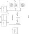
- FIG. 3is a block diagram illustrating a bale forming control system 300.
- control system 300includes a controller 302.
- the controller 302may include one or more controllers 302.
- controller 302may include a main controller and one or more sub controllers.
- sub controllersmay be located in the tractor and baler respectively.
- separate componentse.g. bale density pressure mechanism, PTO drive shaft and pick up
- Control system 300may include a communication device (e.g. an ISOBUS) to provide communication between the tractor and baler to control the PTO speed, travel speed, pick up speed and bale chamber speed.
- the communication devicemay provide communication between the tractor and baler to automatically control the PTO speed while maintaining a certain ground speed of the baler.
- controller 302may be coupled to one or more bale density pressure components 310 (e.g. hydraulic bale density pressure mechanism) configured to apply an amount of density pressure to the rotating bale.
- Controller 302may be coupled to one or more PTO speed components 304 (e.g., a driving mechanism) configured to cause the bale B to be rotated in the bale chamber.
- controller 302may be coupled to the PTO drive shaft 46.
- the PTO drive shaft 46may be coupled to bale chamber components 306 to cause the bale B to be rotated in the bale chamber at a bale chamber speed.
- Controller 302may be configured to cause a bale chamber speed that is fixed relative to the PTO speed.
- Controller 302may also be coupled to one or more pick up speed components 308 in a feeder mechanism configured to pick up crop and feed the crop to the bale chamber.
- controller 302may be coupled to pick up 20 and may be configured to vary the PTO speed relative to a crop pickup speed of the feeder mechanism while the bale chamber speed remains fixed relative to the PTO speed.
- controller 302may also be coupled to one or more operating condition sensors 312 configured to sense at least one operating condition when the bale B is forming.
- the sensors 312may be located on or proximate to a respective component to sense at least one of a bale size; a bale weight; a rate of change of bale size; a rate of change of bale weight; a bale moisture content; a rate of incoming crop flow; an amount of PTO torque; a rate of fuel consumption; and a bale density.
- FIG. 4is a side view of a portion of a baler illustrating different states of a wind guard for use.
- One or more operating condition sensors 312may be located on or proximate to wind guard 402 shown in FIG.
- the incoming crop flow into the bale chambermay be determined based on the sensed position of the wind guard 402 as it moves between the heavy crop position and light crop position shown at FIG. 4 .
- the controller 302may be configured to: (i) receive at least one operating condition value corresponding to the at least one sensed operating condition and control formation of the bale B. In some embodiments, the controller 302 may be configured to automatically determine the amount of bale density pressure applied to the bale responsive to receiving the at least one received operating condition value and cause one or more bale density pressure components to apply the determined amount of bale density pressure to the bale. In some embodiments, the controller 302 may be configured to automatically determine a PTO speed of the driving mechanism responsive to receiving the at least one received operating condition value and cause the determined PTO speed to be applied to the driving mechanism. A bale chamber speed may then be fixed relative to the PTO speed.
- the controller 302may be configured to automatically determine both the bale density pressure and the PTO speed.
- the controller 302may be configured to receive the at least one operating condition value upon request, at predetermined periodic intervals or when the condition value has a value change that is equal to or greater than a predetermined threshold value.
- Embodimentsmay include a method of controlling formation of a bale.
- the methodmay include forming a bale B from crop material by rotating the bale B in a bale chamber, and applying an amount of density pressure to the rotating bale.
- the methodmay also include receiving at least one operating condition value corresponding to at least one sensed operating condition when the bale is forming.
- the methodmay include receiving at least one operating condition value corresponding to at least one sensed operating condition from a group of sensed operating conditions that includes but is not limited to: a bale size; a bale weight; a rate of change of bale size; a rate of change of bale weight; a bale moisture content; a rate of incoming crop flow; an amount of PTO torque; a rate of fuel consumption; and a bale density.
- the methodmay include automatically determining the amount of bale density pressure applied to the bale responsive to receiving the at least one received operating condition value and controlling formation of the bale by causing the determined amount of bale density pressure to be applied to the bale. In some embodiments, the method may include automatically determining a PTO speed responsive to receiving the at least one received operating condition value and controlling formation of the bale by causing the determined PTO speed to be applied. In some embodiments, the method may include both automatically determining the amount of bale density pressure and automatically determining a PTO speed responsive to receiving the at least one received operating condition value. According to one embodiment, the method may include applying a bale chamber speed that is fixed relative to the PTO speed and varying the PTO speed relative to a crop pickup speed while the bale chamber speed remains fixed relative to the PTO speed.
- a density pressuremay be determined to provide a bale having a desired density and the PTO speed that is fixed to the bale chamber speed may be determined to provide the bale having the desired density.
- the balemay then be rotated at a lower bale chamber speed to provide the bale having the desired density, causing the lower of number of rotations, reducing the power and fuel consumption and decreasing crop loss and damage to the bale.
- the tractor's PTO speed and bale chamber speedmay be controlled to increase to provide a faster wrapping time during a net wrapping cycle. In these embodiments, it may be advantageous if the bale was rotating at a greater speed because a greater bale chamber speed may create a shorter net wrapping cycle. If there is little or no material being fed to the bale chamber, the PTO speed and bale chamber speed may be controlled to decrease and the wrapping cycle may be controlled to stop, minimizing power consumption and decreasing crop loss and damage to the bale.
Landscapes
- Life Sciences & Earth Sciences (AREA)
- Environmental Sciences (AREA)
- Harvester Elements (AREA)
- Agricultural Machines (AREA)
Description
- The present disclosure relates generally to automatically controlling the formation of a bale in a baler based on sensed parameters, and particularly to automatically determining the density pressure applied to the bale and the speed of the bale chamber via a PTO speed based on sensed parameters.
- Agricultural balers have been used to consolidate and package crop material to facilitate the storage and handling of the crop material for later use. Typically, a mower-conditioner cuts and conditions the crop material for windrow drying in the sun. When the cut crop material is properly dried, a baler, for example a round baler, the most frequently used in industry, is pulled by a tractor and travels along the windrows to pick up the crop material and form the material into cylindrically-shaped round bales.
- More specifically, the cut crop material is gathered at the front of the baler from along the ground, onto a pickup assembly, and introduced into a bale-forming chamber within the baler. Inside the cut crop is rolled up into a predetermined size. A conventional bale chamber may include a series of belts, chains, and/or rolls that rotate and compress the crop material into the cylindrically-shaped round bale. When the predetermined size is achieved, the cylindrically-shaped round bale is wrapped and bound by net wrapping or other wrapping such as plastic wrapping and wire. After the round bale is wrapped, the back of the baler, or tailgate assembly, opens and the wrapped bale is discharged.
- Each time the bale is rotated in the bale chamber, the bale is compressed creating a higher bale density and providing for more crop material to be formed in the bale. A higher number of revolutions of the bale in the bale chamber, however, increases the amount of power needed and, consequently, increases the amount of fuel consumption. Further, each time the bale rotates, the bale may be damaged by components (e.g., rolls and belts) and crop material may fall out of the baler chamber. An improved method of controlling formation of a bale in a bale chamber is needed.
US 2009/0217827 discloses a round baler having a moisture sensing apparatus and a bale scale of which the information is used to optimize the baling of the next bales. The sensing of the moisture content will start after the bale has reached a predetermined diameter. A history of bale weights is used to estimate how much tension to apply to a belt tensioner to achieve both a target weight and a bale target bale size. A fluid manipulated variable set point is calculated by interpolation or extrapolation from the bale histories. This set point is used to adjust the variable through which hydraulic fluid must pass as the belt tensioner rotates with the growth of the next bale. However, the system ofUS 2009/0217827 uses information of previous bales and is not able to react on changes which occur when forming the present bale.EP 1 008 292 shows a method for producing high-density bales with which it is possible to automatically controlling the pressing power during the formation of the bale upon an interruption or reduction of crop which is fed into the baling chamber of the baler. The baler is provided with means for automatically increasing the pressing power above a predetermined pressing power when product delivery is interrupted or reduced. The underutilized power potential which is available at that point in time is used for increasing the compressed density of the bales while simultaneously providing for a uniform load on the tractor drive. However, by increasing the pressing power, the crop material may be compressed more than needed and the bale may be damaged more resulting in crop material falling out of the baler chamber.- Embodiments provide a method of controlling formation of a bale that includes forming a bale from crop material by: rotating the bale in a bale chamber and applying an amount of density pressure to the rotating bale. The method also includes receiving at least one operating condition value corresponding to at least one sensed operating condition when the bale is forming. The method further includes automatically determining the amount of bale density pressure applied to the bale responsive to receiving the at least one received operating condition value and controlling formation of the bale by causing the determined amount of bale density pressure to be applied to the bale. The method includes automatically determining a PTO speed responsive to receiving the at least one received operating condition value and controlling formation of the bale by causing the determined PTO speed to be applied.
- According to an embodiment, the method includes comprising applying a bale chamber speed that is fixed relative to the PTO speed.
- In an aspect of an embodiment, the method includes varying the PTO speed relative to a crop pickup speed while the bale chamber speed remains fixed relative to the PTO speed.
- In another embodiment, receiving at least one operating condition value further comprises receiving at least one operating condition value corresponding to at least one sensed operating condition from a group of sensed operating conditions comprising: a bale size; a bale weight; a rate of change of bale size; a rate of change of bale weight; a bale moisture content; a rate of incoming crop flow; an amount of PTO torque; a rate of fuel consumption; and a bale density.
- Embodiments provide a bale forming control system that includes a bale chamber configured to form a bale from crop material by rotating the bale in the bale chamber and a bale density pressure mechanism configured to apply an amount of density pressure to the rotating bale. The system also includes at least one sensor configured to sense at least one operating condition when the bale is forming and a controller configured to: (i) receive at least one operating condition value corresponding to the at least one sensed operating condition and control formation of the bale; (ii) automatically determine the amount of bale density pressure applied to the bale responsive to receiving the at least one received operating condition value; and (iii) cause the determined amount of bale density pressure to be applied to the bale. The system also includes a driving mechanism configured to cause the bale to be rotated in the bale chamber. The controller is further configured to: (i) automatically determine a PTO speed of the driving mechanism responsive to receiving the at least one received operating condition value; and (ii) cause the determined PTO speed to be applied to the driving mechanism.
- In an embodiment, the controller is further configured to apply a bale chamber speed that is fixed relative to the PTO speed.
- According to an aspect of an embodiment, the system also includes a feeder mechanism configured to pick up crop and feed the crop to the bale chamber. The controller is further configured to vary the PTO speed relative to a crop pickup speed of the feeder mechanism while the bale chamber speed remains fixed relative to the PTO speed.
- In another embodiment, the at least one sensor is configured to sense at least one operating condition from a group of operating conditions comprising: a bale size; a bale weight; a rate of change of bale size; a rate of change of bale weight; a bale moisture content; a rate of incoming crop flow; an amount of PTO torque; a rate of fuel consumption; and a bale density.
- Additional features and advantages of the invention will be made apparent from the following detailed description of illustrative embodiments that proceeds with reference to the accompanying drawings.
- The foregoing and other aspects of the present invention are best understood from the following detailed description when read in connection with the accompanying drawings. For the purpose of illustrating the invention, there is shown in the drawings embodiments that are presently preferred, it being understood, however, that the invention is not limited to the specific instrumentalities disclosed. Included in the drawings are the following Figures:
FIG. 1 illustrates an exemplary round baler for use with embodiments of the present invention;FIG. 2A and 2B depict side views of a round baler with a bale rotating at different bale chamber speeds.FIG. 2A depicts the baler operating with higher bale chamber speeds, andFIG2B depicts the baler operating with lower bale chamber speeds.FIG. 3 is a block diagram illustrating a bale forming control system for use with embodiments of the present invention; andFIG. 4 is a side view of a portion of a baler illustrating different states of a wind guard for use with embodiments of the present invention.- The number of rotations needed to form a bale of a desired density may be controlled by tractor PTO speed and bale density pressure. Conventional methods and systems for forming bales manually set the PTO speed and bale density pressure prior to the operation of the formation of the bale. Operating conditions that may change during the formation of the bale, however, may affect the number of rotations needed to form a bale of a desired density. These operating conditions may include, but are not limited to, bale size; bale weight; rate of change of bale size; rate of change of bale weight; bale moisture content; rate of incoming crop flow; amount of PTO torque; and rate of fuel consumption.
- Embodiments of the present invention provide an improved system and method of controlling formation of a bale. Embodiments of the present invention minimize the number of bale rotations while still maintaining a desired bale density. Embodiments of the present invention utilize sensors to automatically sense one or more baler conditions during operation and determine at least one of tractor PTO speed and baler hydraulic bale density pressure based on the one or more sensed baler conditions. Embodiments of the present invention automatically sense one or more baler conditions that include bale size, bale weight, rate of change of bale size and rate of change of bale weight, bale moisture content, volume of incoming crop, PTO Torque, tractor fuel usage and bale density.
- Embodiments provide a method of controlling formation of a bale that includes forming a bale from crop material by: rotating the bale in a bale chamber and applying an amount of density pressure to the rotating bale. The method also includes receiving at least one operating condition value corresponding to at least one sensed operating condition when the bale is forming. The method further includes automatically determining the amount of bale density pressure applied to the bale responsive to receiving the at least one received operating condition value and controlling formation of the bale by adjusting the amount of bale density pressure to be applied to the bale relative to the previously determined amount of bale density pressure being applied. In some embodiments, the invention relates to a method of controlling formation of a bale comprising: rotating crop material in a bale chamber and applying an amount of density pressure to the rotating bale; determining one or more conditions of agricultural harvester operation selected from: bale size, bale weight, rate of change of bale size and rate of change of bale weight, bale moisture content, volume of incoming crop, PTO Torque, tractor fuel usage, pressure applied to the bale during rotation; and adjusting the amount of density pressure to the rotating bale such that the adjustment forms the bale with an equal or substantially equal bale density relative to bale density before the adjustment during one or a plurality of operational conditions. In some embodiments, the invention relates to a method of controlling formation of a bale comprising: rotating crop material in a bale chamber and applying an amount of density pressure to the rotating bale; determining one or more operating condition values corresponding to one or more operating conditions of an agricultural harvester selected from: bale size, bale weight, rate of change of bale size and rate of change of bale weight, bale moisture content, volume of incoming crop, PTO Torque, tractor fuel usage, pressure applied to the bale during rotation; and adjusting PTO speed of the driving mechanism responsive to receiving the at least one received operating condition value such that the adjustment f of PTO speed forms the bale with an equal or substantially equal bale density relative to bale density before the adjustment during one or a plurality of operational conditions of the agricultural harvester. In some embodiments, any of the methods disclosed herein comprising the steps of determining one or more operating condition values corresponding to one or more operating conditions of an agricultural harvester and adjusting PTO speed or the amount of density pressure to the rotating bale are performed by one or a series of controllers operably linked to one or more sensors. In some embodiments, wherein the one or more controllers are configured to: (i) automatically determine a PTO speed of the driving mechanism responsive to receiving the at least one received operating condition value; and (ii) cause the determined PTO speed to be applied to the driving mechanism.
- Embodiments of the present invention are particularly well suited for, but in no way limited to, use with agricultural harvesters and agricultural balers, for example, such as round balers. In some embodiments, the present invention is configured for inclusion in combines, cotton harvesters, waste balers, or round balers comprising a bale chamber adapted for rotation and formation of a bale. Agricultural balers, such as round balers, are well known in the agricultural industry, and the instant invention can be used with substantially any of such machines.
FIG. 1 illustrates an exemplary round baler for use with embodiments of the present invention. As shown inFIG. 1 ,round baler 10 is enclosed by amain frame 12, comprising a plurality of rigid structural elements including a pair ofside walls 14.Main frame 12 is supported by a pair ofrear wheels 13. A forwardly mountedhitch 40, integrated with themain frame 12, provides for connection to a tractor (not shown). As shown, a power take off (PTO)shaft 46, is located herein above thehitch 40. In other balers, the PTO shaft may be located and connected to the tractor below the hitch. The PTO shaft draws energy from a tractor driving the hitch and transfers that energy to drive mechanisms in thebaler 10.Rear side 16, typically comprises a tailgate which is closed during baling and opened to eject finished bales. In conventional balers, storage to house spare net rolls is typically located about the tailgate.- Also shown in
FIG. 1 is thefront side 15 of the baler. This side faces the rear of a tractor (not shown) as connected to by thehitch 40 andPTO shaft 46. At the bottom of the front side, between a front pair ofwheels 13a, and mounted to themainframe 12, is thepickup 20. Thepickup 20 is supported by the pair offront wheels 13a.Pickup tines 22 wrap around and connect within thepickup 20. The tips of thetines 22 are movable along a predetermined path along the ground to lift crop material from the ground and deliver it rearward along a generally horizontal path toward a floor roll (not shown) at the bottom of the baler, which is rotatably mounted onmain frame 12. During baling, the floor roll conveys crop material further rear into a bale chamber where belts then urge the material upwardly and forwardly into engagement with sledge rolls. The sledge rolls coil crop material in a round direction to form and add to a bale core. Continued feeding bypickup tines 22 urge additional crop material into the forming bale in a generally spiral fashion growing the bale core. - Components of balers may operate at different speeds, affecting the formation of the bales in the bale chamber. These speeds may include PTO speed, bale chamber speed, pick up speed and travel speed. PTO speed is the speed of the
PTO shaft 46 that draws energy from a tractor to drive mechanisms in thebaler 10. Conventional balers and tractors operate at a fixed PTO speed. Part of the PTO drive train is coupled to the bale chamber. Another part of the PTO drive train is coupled to thepickup 20 of a feeding mechanism in the baler. The bale chamber speed is the rotational speed of the bale turning in the baler. The pickup speed is the speed of the pickup, (e.g., speed of a rotor feeder or stuffer controlling the rate of crop flowing into the bale chamber. The travel speed is the ground speed of the tractor and baler combination. Typically, the pickup speed and the ground speed together are adjusted with respect to each other. For example, as the travel speed increases, the pickup speed is also increased to collect or harvest the crop material. If an operator is driving an agricultural harvester comprising a bale chamber and a pickup at a slow rate of speed, the pickup may not need to operate as fast as when the operator is driving the agricultural harvester as a quick rate of speed. As the travel speed decreases, the pickup speed may also be adjusted (in this case, decreased) to collect or harvest the same volume of crop material into the bale chamber. In some embodiments, the adjustment of the speed of the pickup positively impacts the rate at which the density of the bale forms in the bale chamber during operational conditions. In some embodiments, the invention relates to a method of maintaining a constant density of a bale in a bale chamber during harvesting of crop material using any of the disclosed harvesters such as balers disclosed herein. - As described above, a higher number of revolutions of the bale in the bale chamber may increase fuel consumption, damage the bale and cause more crop material to fall out of the baler chamber.
FIG. 2A and FIG. 2B illustrate bales formed from different number of rotations. The number of rotations needed to form a bale B of a desired density may be controlled by the bale density pressure and by bale chamber speed via the PTO speed. Conventional methods and systems for forming bales manually set the PTO speed and bale density pressure prior to the operation of the formation of the bale. Operating conditions that may change during the formation of the bale, however, may affect the number of rotations needed to form a bale of a desired density. FIG. 3 is a block diagram illustrating a bale formingcontrol system 300. As shown,control system 300 includes acontroller 302. Thecontroller 302 may include one ormore controllers 302. In some embodiments,controller 302 may include a main controller and one or more sub controllers. In some aspects, sub controllers may be located in the tractor and baler respectively. In some aspects, separate components (e.g. bale density pressure mechanism, PTO drive shaft and pick up) may have respective sub controllers that receive instructions from the main controller.Control system 300 may include a communication device (e.g. an ISOBUS) to provide communication between the tractor and baler to control the PTO speed, travel speed, pick up speed and bale chamber speed. In some aspects, the communication device may provide communication between the tractor and baler to automatically control the PTO speed while maintaining a certain ground speed of the baler.- As shown at
FIG. 3 ,controller 302 may be coupled to one or more bale density pressure components 310 (e.g. hydraulic bale density pressure mechanism) configured to apply an amount of density pressure to the rotating bale.Controller 302 may be coupled to one or more PTO speed components 304 (e.g., a driving mechanism) configured to cause the bale B to be rotated in the bale chamber. For example,controller 302 may be coupled to thePTO drive shaft 46. ThePTO drive shaft 46 may be coupled tobale chamber components 306 to cause the bale B to be rotated in the bale chamber at a bale chamber speed.Controller 302 may be configured to cause a bale chamber speed that is fixed relative to the PTO speed.Controller 302 may also be coupled to one or more pick upspeed components 308 in a feeder mechanism configured to pick up crop and feed the crop to the bale chamber. For example,controller 302 may be coupled to pick up 20 and may be configured to vary the PTO speed relative to a crop pickup speed of the feeder mechanism while the bale chamber speed remains fixed relative to the PTO speed. - As shown at
FIG. 3 ,controller 302 may also be coupled to one or moreoperating condition sensors 312 configured to sense at least one operating condition when the bale B is forming. Thesensors 312 may be located on or proximate to a respective component to sense at least one of a bale size; a bale weight; a rate of change of bale size; a rate of change of bale weight; a bale moisture content; a rate of incoming crop flow; an amount of PTO torque; a rate of fuel consumption; and a bale density. For example,FIG. 4 is a side view of a portion of a baler illustrating different states of a wind guard for use. One or moreoperating condition sensors 312 may be located on or proximate towind guard 402 shown inFIG. 4 to sense the position of thatwind guard 402 and the incoming crop flow into the bale chamber. The incoming crop flow into the bale chamber may be determined based on the sensed position of thewind guard 402 as it moves between the heavy crop position and light crop position shown atFIG. 4 . - The
controller 302 may be configured to: (i) receive at least one operating condition value corresponding to the at least one sensed operating condition and control formation of the bale B. In some embodiments, thecontroller 302 may be configured to automatically determine the amount of bale density pressure applied to the bale responsive to receiving the at least one received operating condition value and cause one or more bale density pressure components to apply the determined amount of bale density pressure to the bale. In some embodiments, thecontroller 302 may be configured to automatically determine a PTO speed of the driving mechanism responsive to receiving the at least one received operating condition value and cause the determined PTO speed to be applied to the driving mechanism. A bale chamber speed may then be fixed relative to the PTO speed. In some embodiments, thecontroller 302 may be configured to automatically determine both the bale density pressure and the PTO speed. Thecontroller 302 may be configured to receive the at least one operating condition value upon request, at predetermined periodic intervals or when the condition value has a value change that is equal to or greater than a predetermined threshold value. - Embodiments may include a method of controlling formation of a bale. The method may include forming a bale B from crop material by rotating the bale B in a bale chamber, and applying an amount of density pressure to the rotating bale. The method may also include receiving at least one operating condition value corresponding to at least one sensed operating condition when the bale is forming. In some embodiments, the method may include receiving at least one operating condition value corresponding to at least one sensed operating condition from a group of sensed operating conditions that includes but is not limited to: a bale size; a bale weight; a rate of change of bale size; a rate of change of bale weight; a bale moisture content; a rate of incoming crop flow; an amount of PTO torque; a rate of fuel consumption; and a bale density.
- In some embodiments, the method may include automatically determining the amount of bale density pressure applied to the bale responsive to receiving the at least one received operating condition value and controlling formation of the bale by causing the determined amount of bale density pressure to be applied to the bale. In some embodiments, the method may include automatically determining a PTO speed responsive to receiving the at least one received operating condition value and controlling formation of the bale by causing the determined PTO speed to be applied. In some embodiments, the method may include both automatically determining the amount of bale density pressure and automatically determining a PTO speed responsive to receiving the at least one received operating condition value. According to one embodiment, the method may include applying a bale chamber speed that is fixed relative to the PTO speed and varying the PTO speed relative to a crop pickup speed while the bale chamber speed remains fixed relative to the PTO speed.
- For example, a density pressure may be determined to provide a bale having a desired density and the PTO speed that is fixed to the bale chamber speed may be determined to provide the bale having the desired density. The bale may then be rotated at a lower bale chamber speed to provide the bale having the desired density, causing the lower of number of rotations, reducing the power and fuel consumption and decreasing crop loss and damage to the bale.
- In some embodiments, the tractor's PTO speed and bale chamber speed may be controlled to increase to provide a faster wrapping time during a net wrapping cycle. In these embodiments, it may be advantageous if the bale was rotating at a greater speed because a greater bale chamber speed may create a shorter net wrapping cycle. If there is little or no material being fed to the bale chamber, the PTO speed and bale chamber speed may be controlled to decrease and the wrapping cycle may be controlled to stop, minimizing power consumption and decreasing crop loss and damage to the bale.
- Although the invention has been described with reference to exemplary embodiments, it is not limited thereto. Those skilled in the art will appreciate that numerous changes and modifications may be made to the preferred embodiments of the invention and that such changes and modifications may be made without departing from the scope of the invention. It is therefore intended that the appended claims be construed to cover all such equivalent variations as fall within the scope of the invention.
Claims (9)
- A bale forming control system comprising:- a bale chamber configured to form a bale (B) from crop material by rotating the bale (B) in the bale chamber;- a drive mechanism configured to cause the bale (B) to be rotated in the bale chamber;- a bale density pressure mechanism configured to apply an amount of density pressure to the rotating bale (B);- at least one sensor (312) configured to sense at least one operating condition when the bale (B) is forming; and- a controller (302) configured to: (i) receive at least one operating condition value corresponding to the at least one sensed operating condition and control formation of the bale (B); (ii) automatically determine the amount of bale density pressure applied to the bale (B) responsive to receiving the at least one received operating condition value; and (iii) cause the determined amount of bale density pressure to be applied to the bale (B)characterized in that the controller (302) is further configured to (i) automatically determine a PTO speed of the driving mechanism responsive to receiving the at least one received operating condition value; and (ii) cause the determined PTO speed to be applied to the driving mechanism.
- The bale forming control system of claim 1, wherein the controller (302) is further configured to apply a bale chamber speed that is fixed relative to the PTO speed.
- The bale forming control system of any of claims 1 or 2, further comprising a feeder mechanism configured to pick up crop and feed the crop to the bale chamber, and wherein the controller (302) is further configured to vary the PTO speed relative to a crop pickup speed of the feeder mechanism while the bale chamber speed remains fixed relative to the PTO speed.
- The bale forming control system of any of claims 1 to 3, wherein the at least one sensor (312) is configured to sense at least one operating condition from a group of operating conditions comprising: a bale size; a bale weight; a rate of change of bale size; a rate of change of bale weight; a bale moisture content; a rate of incoming crop flow; an amount of PTO torque; a rate of fuel consumption; and a bale density.
- An agricultural harvester comprising the bale forming control system of any of claim 1 to 4.
- A method of controlling formation of a bale (B) using the system of claims 1-4 in an agricultural harvester comprising:- rotating a bale (B) of crop material in a bale chamber, and- applying an amount of density pressure to the rotating bale (B);- receiving at least one operating condition value corresponding to at least one sensed operating condition when the bale (B) is forming;- automatically determining an amount of bale density pressure applied to the bale (B) responsive to receiving the at least one received operating condition value;- applying the amount of bale density pressure applied to the bale (B) responsive to receiving the at least one received operating condition value to the bale (B);- automatically determining a PTO speed of a drive mechanism responsive to receiving the at least one received operating condition value; and- applying the determined PTO speed to the drive mechanism.
- The method of claim 6, further comprising applying a bale chamber speed that is fixed relative to the PTO speed.
- The method of any of claims 6 to 7, further comprising varying the PTO speed relative to a crop pickup speed while the bale chamber speed remains fixed relative to the PTO speed.
- The method of any of claims 6 to 8, wherein receiving at least one operating condition value further comprises receiving at least one operating condition value corresponding to at least one or a combination of sensed operating conditions selected from: a bale size; a bale weight; a rate of change of bale size; a rate of change of bale weight; a bale moisture content; a rate of incoming crop flow; an amount of PTO torque; a rate of fuel consumption; and a bale density.
Applications Claiming Priority (1)
| Application Number | Priority Date | Filing Date | Title |
|---|---|---|---|
| US201361798441P | 2013-03-15 | 2013-03-15 |
Publications (2)
| Publication Number | Publication Date |
|---|---|
| EP2777383A1 EP2777383A1 (en) | 2014-09-17 |
| EP2777383B1true EP2777383B1 (en) | 2017-06-28 |
Family
ID=50272519
Family Applications (1)
| Application Number | Title | Priority Date | Filing Date |
|---|---|---|---|
| EP14160046.0AActiveEP2777383B1 (en) | 2013-03-15 | 2014-03-14 | Bale forming control system and method |
Country Status (2)
| Country | Link |
|---|---|
| US (2) | US20140261023A1 (en) |
| EP (1) | EP2777383B1 (en) |
Families Citing this family (16)
| Publication number | Priority date | Publication date | Assignee | Title |
|---|---|---|---|---|
| NL1037742C2 (en)* | 2010-02-23 | 2011-08-24 | Forage Innovations Bv | Wrapper for wrapping bales of crop material. |
| US9854744B2 (en)* | 2014-12-11 | 2018-01-02 | Cnh Industrial America Llc | Adjusting bale density setting based on bale weight and/or moisture |
| US10058038B2 (en)* | 2015-05-22 | 2018-08-28 | Cnh Industrial America Llc | System and method for continuous bale forming |
| NL2016211B1 (en) | 2016-02-03 | 2017-08-11 | Forage Co Bv | Agricultural vehicle with a loading chamber and storing method with a crop material property sensor. |
| CN107624381A (en)* | 2016-12-03 | 2018-01-26 | 呼伦贝尔市瑞丰农牧业科技有限公司 | Machine for forming cylindrical bale automatic control system |
| JP6854258B2 (en)* | 2018-03-30 | 2021-04-07 | ヤンマーパワーテクノロジー株式会社 | Work vehicle |
| EP3679784B1 (en)* | 2019-01-09 | 2021-12-01 | Deere & Company | Round baler |
| US11026371B2 (en) | 2019-04-10 | 2021-06-08 | Cnh Industrial America Llc | Agricultural baler with bale formation control based on power requirements and usage |
| US11690323B2 (en)* | 2020-02-27 | 2023-07-04 | Cnh Industrial America Llc | Agricultural baler with pivotable roll having external portion |
| US12089536B2 (en)* | 2020-05-19 | 2024-09-17 | Cnh Industrial America Llc | Agricultural vehicle with retainer for blockage removing windguard |
| US11974522B2 (en) | 2020-12-23 | 2024-05-07 | Cnh Industrial America Llc | Method and control system for controlling baler power-take-off speed |
| EP4079142A1 (en)* | 2021-04-20 | 2022-10-26 | Agco Corporation | Systems for monitoring and using mat thickness and bale growth rate |
| US12035659B2 (en)* | 2021-06-23 | 2024-07-16 | Cnh Industrial America Llc | Agricultural implement system with a controller for detecting and mitigating plug conditions |
| GB202114623D0 (en) | 2021-10-13 | 2021-11-24 | Agco Int Gmbh | Baling apparatus |
| US12408592B2 (en) | 2022-06-10 | 2025-09-09 | Cnh Industrial America Llc | Agricultural baler system with bale stall identification |
| CN115226504B (en)* | 2022-08-15 | 2024-09-06 | 广东皓耘科技有限公司 | Intelligent control system and bundling machine |
Family Cites Families (33)
| Publication number | Priority date | Publication date | Assignee | Title |
|---|---|---|---|---|
| US2576784A (en) | 1949-09-09 | 1951-11-27 | Dodds Galen | Automatic hay baler control |
| US3022622A (en) | 1959-09-24 | 1962-02-27 | Sperry Rand Corp | Baler control device |
| US3525302A (en) | 1968-06-03 | 1970-08-25 | Sperry Rand Corp | Step-up drive for a baling machine |
| US3901007A (en) | 1973-04-24 | 1975-08-26 | Sperry Rand Corp | Hay roll forming machine |
| US4132163A (en) | 1976-04-09 | 1979-01-02 | Hesston Corporation | Baler loading method |
| EP0150629B1 (en) | 1984-01-27 | 1988-04-06 | JOHN DEERE (Société Anonyme) | Roundbaler with torque limiter |
| EP0150631B1 (en) | 1984-01-27 | 1988-01-13 | JOHN DEERE (Société Anonyme) | Rotobaler with driven bale starter roll |
| US5131214A (en)* | 1991-01-15 | 1992-07-21 | Vermeer Manufacturing Company | Baler fill monitor |
| IT1277868B1 (en) | 1995-07-24 | 1997-11-12 | Antonio Feraboli | ROUND BALER FOR COLLECTING AND FORMING CYLINDRICAL BALES OF FORAGE OR STRAW, OF THE VARIABLE CHAMBER TYPE, WITH CHAMBER |
| DE19531240A1 (en) | 1995-08-25 | 1997-02-27 | Same Spa | Baler, especially self-propelled large baler |
| US5622104A (en)* | 1995-08-28 | 1997-04-22 | Gehl Company | Cylindrical baler having hydraulic circuit for controlling bale density and tailgate operation |
| DE19856977A1 (en)* | 1998-12-10 | 2000-06-15 | Lely Welger Maschinenfabrik Gm | Method and device for producing high-density round bales from agricultural crops |
| US6431981B1 (en) | 1999-06-30 | 2002-08-13 | Wisconsin Alumni Research Foundation | Yield monitor for forage crops |
| US6272825B1 (en) | 1999-09-15 | 2001-08-14 | Hay & Forage Industries | Round baler having hydraulically sequenced clutch and tailgate cylinders |
| DE10023443A1 (en) | 2000-05-12 | 2001-11-15 | Deere & Co | Conveyor |
| GB2362127B (en) | 2000-05-13 | 2002-05-22 | Ford New Holland Nv | Method and apparatus for controlling a tractor/baler combination |
| US6543342B2 (en) | 2000-06-29 | 2003-04-08 | New Holland North America, Inc. | Method for determining a value relating to compressing rate of a baler |
| US6633798B2 (en) | 2001-07-31 | 2003-10-14 | L & P Property Management Company | Control system for baling machine |
| US6975911B2 (en) | 2001-07-31 | 2005-12-13 | L&P Property Management Company | Operator input interface for baling machine |
| US6651416B2 (en) | 2002-02-28 | 2003-11-25 | Deere & Company | Large rectangular baler having hydraulically powered functions, and control system therefor |
| DE10211800A1 (en) | 2002-03-16 | 2003-10-02 | Deere & Co | Device for detecting the presence of a crop flow in a harvesting machine |
| US6874311B2 (en) | 2002-10-24 | 2005-04-05 | Deere & Company | Crop recovery machine |
| US7104191B1 (en) | 2005-05-27 | 2006-09-12 | Deere & Company | Method of maximizing baler throughput |
| DE102005029405B4 (en) | 2005-06-24 | 2014-05-15 | Deere & Company | Combination of a farm machine and a baler |
| DE102005040174A1 (en) | 2005-08-25 | 2007-03-15 | Deere & Company, Moline | Agricultural press |
| DE102005059127A1 (en) | 2005-12-10 | 2007-06-28 | Deere & Company, Moline | Baler with a moisture measuring device |
| US7703391B2 (en)* | 2006-07-28 | 2010-04-27 | Vermeer Manufacturing Company | Round baler with scale and moisture meter |
| US7437866B2 (en)* | 2006-12-20 | 2008-10-21 | Cnh America Llc | Sensor for bale shape monitoring in round balers |
| US20110023732A1 (en)* | 2009-07-31 | 2011-02-03 | Agco Corporation | Round Baler With Variable Speed Baling Mechanism |
| US8291687B2 (en)* | 2009-07-31 | 2012-10-23 | Agco Corporation | Continuous round baler |
| US8311709B2 (en)* | 2009-09-08 | 2012-11-13 | Cnh America Llc | Implement initiated control of tractor power take-off (PTO) |
| BE1019006A3 (en)* | 2009-11-19 | 2011-12-06 | Cnh Belgium Nv | A TRACTOR WITH A STEERING DEVICE. |
| US10098282B2 (en)* | 2011-12-23 | 2018-10-16 | Agco Corporation | Variable speed round bale chamber control using bale growth rate |
- 2014
- 2014-03-14EPEP14160046.0Apatent/EP2777383B1/enactiveActive
- 2014-03-14USUS14/214,403patent/US20140261023A1/ennot_activeAbandoned
- 2020
- 2020-02-03USUS16/780,473patent/US11751511B2/enactiveActive
Also Published As
| Publication number | Publication date |
|---|---|
| US20140261023A1 (en) | 2014-09-18 |
| US20200229351A1 (en) | 2020-07-23 |
| US11751511B2 (en) | 2023-09-12 |
| EP2777383A1 (en) | 2014-09-17 |
Similar Documents
| Publication | Publication Date | Title |
|---|---|---|
| US11751511B2 (en) | Bale forming control system and method | |
| EP3031317B1 (en) | Adjusting bale density setting based on bale weight and/or moisture | |
| US8677724B2 (en) | Round baler for baling crop residue | |
| EP3192347B1 (en) | Continuous harvester with crop supply chamber | |
| EP3192349B1 (en) | Continuous harvester with crop supply chamber | |
| EP3192348B1 (en) | Continuous harvester with crop supply chamber | |
| US11272669B2 (en) | Draper pickup with crop distribution for agricultural baler | |
| EP3141106B1 (en) | Operation and control of bottom floor assembly | |
| EP3837963B1 (en) | Methods and systems for measuring throughput in agricultural equipment | |
| EP3760032B1 (en) | Variable chamber baler | |
| EP3269228B1 (en) | Net wrapping system | |
| EP3087827B1 (en) | Tailgate motion adjustment system | |
| US12408592B2 (en) | Agricultural baler system with bale stall identification | |
| US20250185547A1 (en) | Feedrate control for round baler | |
| US20250185546A1 (en) | Variable pickup speed control for controlling shape of a round bale | |
| US10813292B2 (en) | Hydraulic feed roll adjustment system | |
| US20250185544A1 (en) | Variable speed pickup for round baler |
Legal Events
| Date | Code | Title | Description |
|---|---|---|---|
| 17P | Request for examination filed | Effective date:20140314 | |
| AK | Designated contracting states | Kind code of ref document:A1 Designated state(s):AL AT BE BG CH CY CZ DE DK EE ES FI FR GB GR HR HU IE IS IT LI LT LU LV MC MK MT NL NO PL PT RO RS SE SI SK SM TR | |
| AX | Request for extension of the european patent | Extension state:BA ME | |
| PUAI | Public reference made under article 153(3) epc to a published international application that has entered the european phase | Free format text:ORIGINAL CODE: 0009012 | |
| R17P | Request for examination filed (corrected) | Effective date:20150317 | |
| RBV | Designated contracting states (corrected) | Designated state(s):AL AT BE BG CH CY CZ DE DK EE ES FI FR GB GR HR HU IE IS IT LI LT LU LV MC MK MT NL NO PL PT RO RS SE SI SK SM TR | |
| 17Q | First examination report despatched | Effective date:20150715 | |
| GRAP | Despatch of communication of intention to grant a patent | Free format text:ORIGINAL CODE: EPIDOSNIGR1 | |
| STAA | Information on the status of an ep patent application or granted ep patent | Free format text:STATUS: GRANT OF PATENT IS INTENDED | |
| INTG | Intention to grant announced | Effective date:20170119 | |
| RIN1 | Information on inventor provided before grant (corrected) | Inventor name:SMITH, KEVIN M. Inventor name:GARDUS, JOHN Inventor name:VAN GROENIGEN, JAN Inventor name:POSSELIUS, JOHN H. | |
| GRAS | Grant fee paid | Free format text:ORIGINAL CODE: EPIDOSNIGR3 | |
| GRAA | (expected) grant | Free format text:ORIGINAL CODE: 0009210 | |
| STAA | Information on the status of an ep patent application or granted ep patent | Free format text:STATUS: THE PATENT HAS BEEN GRANTED | |
| AK | Designated contracting states | Kind code of ref document:B1 Designated state(s):AL AT BE BG CH CY CZ DE DK EE ES FI FR GB GR HR HU IE IS IT LI LT LU LV MC MK MT NL NO PL PT RO RS SE SI SK SM TR | |
| REG | Reference to a national code | Ref country code:GB Ref legal event code:FG4D | |
| REG | Reference to a national code | Ref country code:CH Ref legal event code:EP | |
| REG | Reference to a national code | Ref country code:DE Ref legal event code:R084 Ref document number:602014011127 Country of ref document:DE | |
| REG | Reference to a national code | Ref country code:AT Ref legal event code:REF Ref document number:904000 Country of ref document:AT Kind code of ref document:T Effective date:20170715 | |
| REG | Reference to a national code | Ref country code:IE Ref legal event code:FG4D | |
| REG | Reference to a national code | Ref country code:DE Ref legal event code:R096 Ref document number:602014011127 Country of ref document:DE | |
| REG | Reference to a national code | Ref country code:NL Ref legal event code:FP | |
| PG25 | Lapsed in a contracting state [announced via postgrant information from national office to epo] | Ref country code:GR Free format text:LAPSE BECAUSE OF FAILURE TO SUBMIT A TRANSLATION OF THE DESCRIPTION OR TO PAY THE FEE WITHIN THE PRESCRIBED TIME-LIMIT Effective date:20170929 Ref country code:HR Free format text:LAPSE BECAUSE OF FAILURE TO SUBMIT A TRANSLATION OF THE DESCRIPTION OR TO PAY THE FEE WITHIN THE PRESCRIBED TIME-LIMIT Effective date:20170628 Ref country code:FI Free format text:LAPSE BECAUSE OF FAILURE TO SUBMIT A TRANSLATION OF THE DESCRIPTION OR TO PAY THE FEE WITHIN THE PRESCRIBED TIME-LIMIT Effective date:20170628 Ref country code:LT Free format text:LAPSE BECAUSE OF FAILURE TO SUBMIT A TRANSLATION OF THE DESCRIPTION OR TO PAY THE FEE WITHIN THE PRESCRIBED TIME-LIMIT Effective date:20170628 Ref country code:NO Free format text:LAPSE BECAUSE OF FAILURE TO SUBMIT A TRANSLATION OF THE DESCRIPTION OR TO PAY THE FEE WITHIN THE PRESCRIBED TIME-LIMIT Effective date:20170928 | |
| REG | Reference to a national code | Ref country code:LT Ref legal event code:MG4D | |
| REG | Reference to a national code | Ref country code:AT Ref legal event code:MK05 Ref document number:904000 Country of ref document:AT Kind code of ref document:T Effective date:20170628 | |
| PG25 | Lapsed in a contracting state [announced via postgrant information from national office to epo] | Ref country code:RS Free format text:LAPSE BECAUSE OF FAILURE TO SUBMIT A TRANSLATION OF THE DESCRIPTION OR TO PAY THE FEE WITHIN THE PRESCRIBED TIME-LIMIT Effective date:20170628 Ref country code:LV Free format text:LAPSE BECAUSE OF FAILURE TO SUBMIT A TRANSLATION OF THE DESCRIPTION OR TO PAY THE FEE WITHIN THE PRESCRIBED TIME-LIMIT Effective date:20170628 Ref country code:BG Free format text:LAPSE BECAUSE OF FAILURE TO SUBMIT A TRANSLATION OF THE DESCRIPTION OR TO PAY THE FEE WITHIN THE PRESCRIBED TIME-LIMIT Effective date:20170928 Ref country code:SE Free format text:LAPSE BECAUSE OF FAILURE TO SUBMIT A TRANSLATION OF THE DESCRIPTION OR TO PAY THE FEE WITHIN THE PRESCRIBED TIME-LIMIT Effective date:20170628 | |
| REG | Reference to a national code | Ref country code:FR Ref legal event code:PLFP Year of fee payment:5 | |
| PG25 | Lapsed in a contracting state [announced via postgrant information from national office to epo] | Ref country code:CZ Free format text:LAPSE BECAUSE OF FAILURE TO SUBMIT A TRANSLATION OF THE DESCRIPTION OR TO PAY THE FEE WITHIN THE PRESCRIBED TIME-LIMIT Effective date:20170628 Ref country code:AT Free format text:LAPSE BECAUSE OF FAILURE TO SUBMIT A TRANSLATION OF THE DESCRIPTION OR TO PAY THE FEE WITHIN THE PRESCRIBED TIME-LIMIT Effective date:20170628 Ref country code:SK Free format text:LAPSE BECAUSE OF FAILURE TO SUBMIT A TRANSLATION OF THE DESCRIPTION OR TO PAY THE FEE WITHIN THE PRESCRIBED TIME-LIMIT Effective date:20170628 Ref country code:EE Free format text:LAPSE BECAUSE OF FAILURE TO SUBMIT A TRANSLATION OF THE DESCRIPTION OR TO PAY THE FEE WITHIN THE PRESCRIBED TIME-LIMIT Effective date:20170628 Ref country code:RO Free format text:LAPSE BECAUSE OF FAILURE TO SUBMIT A TRANSLATION OF THE DESCRIPTION OR TO PAY THE FEE WITHIN THE PRESCRIBED TIME-LIMIT Effective date:20170628 | |
| PG25 | Lapsed in a contracting state [announced via postgrant information from national office to epo] | Ref country code:PL Free format text:LAPSE BECAUSE OF FAILURE TO SUBMIT A TRANSLATION OF THE DESCRIPTION OR TO PAY THE FEE WITHIN THE PRESCRIBED TIME-LIMIT Effective date:20170628 Ref country code:ES Free format text:LAPSE BECAUSE OF FAILURE TO SUBMIT A TRANSLATION OF THE DESCRIPTION OR TO PAY THE FEE WITHIN THE PRESCRIBED TIME-LIMIT Effective date:20170628 Ref country code:IS Free format text:LAPSE BECAUSE OF FAILURE TO SUBMIT A TRANSLATION OF THE DESCRIPTION OR TO PAY THE FEE WITHIN THE PRESCRIBED TIME-LIMIT Effective date:20171028 Ref country code:SM Free format text:LAPSE BECAUSE OF FAILURE TO SUBMIT A TRANSLATION OF THE DESCRIPTION OR TO PAY THE FEE WITHIN THE PRESCRIBED TIME-LIMIT Effective date:20170628 | |
| REG | Reference to a national code | Ref country code:DE Ref legal event code:R097 Ref document number:602014011127 Country of ref document:DE | |
| PG25 | Lapsed in a contracting state [announced via postgrant information from national office to epo] | Ref country code:DK Free format text:LAPSE BECAUSE OF FAILURE TO SUBMIT A TRANSLATION OF THE DESCRIPTION OR TO PAY THE FEE WITHIN THE PRESCRIBED TIME-LIMIT Effective date:20170628 | |
| PLBE | No opposition filed within time limit | Free format text:ORIGINAL CODE: 0009261 | |
| STAA | Information on the status of an ep patent application or granted ep patent | Free format text:STATUS: NO OPPOSITION FILED WITHIN TIME LIMIT | |
| 26N | No opposition filed | Effective date:20180329 | |
| PG25 | Lapsed in a contracting state [announced via postgrant information from national office to epo] | Ref country code:SI Free format text:LAPSE BECAUSE OF FAILURE TO SUBMIT A TRANSLATION OF THE DESCRIPTION OR TO PAY THE FEE WITHIN THE PRESCRIBED TIME-LIMIT Effective date:20170628 | |
| REG | Reference to a national code | Ref country code:CH Ref legal event code:PL | |
| PG25 | Lapsed in a contracting state [announced via postgrant information from national office to epo] | Ref country code:MC Free format text:LAPSE BECAUSE OF FAILURE TO SUBMIT A TRANSLATION OF THE DESCRIPTION OR TO PAY THE FEE WITHIN THE PRESCRIBED TIME-LIMIT Effective date:20170628 | |
| REG | Reference to a national code | Ref country code:BE Ref legal event code:MM Effective date:20180331 | |
| REG | Reference to a national code | Ref country code:IE Ref legal event code:MM4A | |
| PG25 | Lapsed in a contracting state [announced via postgrant information from national office to epo] | Ref country code:LU Free format text:LAPSE BECAUSE OF NON-PAYMENT OF DUE FEES Effective date:20180314 | |
| PG25 | Lapsed in a contracting state [announced via postgrant information from national office to epo] | Ref country code:IE Free format text:LAPSE BECAUSE OF NON-PAYMENT OF DUE FEES Effective date:20180314 | |
| PG25 | Lapsed in a contracting state [announced via postgrant information from national office to epo] | Ref country code:CH Free format text:LAPSE BECAUSE OF NON-PAYMENT OF DUE FEES Effective date:20180331 Ref country code:BE Free format text:LAPSE BECAUSE OF NON-PAYMENT OF DUE FEES Effective date:20180331 Ref country code:LI Free format text:LAPSE BECAUSE OF NON-PAYMENT OF DUE FEES Effective date:20180331 | |
| PG25 | Lapsed in a contracting state [announced via postgrant information from national office to epo] | Ref country code:MT Free format text:LAPSE BECAUSE OF NON-PAYMENT OF DUE FEES Effective date:20180314 | |
| PG25 | Lapsed in a contracting state [announced via postgrant information from national office to epo] | Ref country code:TR Free format text:LAPSE BECAUSE OF FAILURE TO SUBMIT A TRANSLATION OF THE DESCRIPTION OR TO PAY THE FEE WITHIN THE PRESCRIBED TIME-LIMIT Effective date:20170628 | |
| PG25 | Lapsed in a contracting state [announced via postgrant information from national office to epo] | Ref country code:HU Free format text:LAPSE BECAUSE OF FAILURE TO SUBMIT A TRANSLATION OF THE DESCRIPTION OR TO PAY THE FEE WITHIN THE PRESCRIBED TIME-LIMIT; INVALID AB INITIO Effective date:20140314 Ref country code:PT Free format text:LAPSE BECAUSE OF FAILURE TO SUBMIT A TRANSLATION OF THE DESCRIPTION OR TO PAY THE FEE WITHIN THE PRESCRIBED TIME-LIMIT Effective date:20170628 | |
| PG25 | Lapsed in a contracting state [announced via postgrant information from national office to epo] | Ref country code:MK Free format text:LAPSE BECAUSE OF NON-PAYMENT OF DUE FEES Effective date:20170628 Ref country code:CY Free format text:LAPSE BECAUSE OF FAILURE TO SUBMIT A TRANSLATION OF THE DESCRIPTION OR TO PAY THE FEE WITHIN THE PRESCRIBED TIME-LIMIT Effective date:20170628 | |
| REG | Reference to a national code | Ref country code:DE Ref legal event code:R082 Ref document number:602014011127 Country of ref document:DE Representative=s name:MEISSNER BOLTE PATENTANWAELTE RECHTSANWAELTE P, DE | |
| PG25 | Lapsed in a contracting state [announced via postgrant information from national office to epo] | Ref country code:AL Free format text:LAPSE BECAUSE OF FAILURE TO SUBMIT A TRANSLATION OF THE DESCRIPTION OR TO PAY THE FEE WITHIN THE PRESCRIBED TIME-LIMIT Effective date:20170628 | |
| PGFP | Annual fee paid to national office [announced via postgrant information from national office to epo] | Ref country code:NL Payment date:20240320 Year of fee payment:11 | |
| PGFP | Annual fee paid to national office [announced via postgrant information from national office to epo] | Ref country code:DE Payment date:20250327 Year of fee payment:12 | |
| PGFP | Annual fee paid to national office [announced via postgrant information from national office to epo] | Ref country code:FR Payment date:20250324 Year of fee payment:12 | |
| PGFP | Annual fee paid to national office [announced via postgrant information from national office to epo] | Ref country code:IT Payment date:20250321 Year of fee payment:12 Ref country code:GB Payment date:20250325 Year of fee payment:12 |